user's guide -...
TRANSCRIPT

PN 3729502 March 2014 © 2014 Fluke Corporation. All rights reserved. Specifications are subject to change without notice. All product names are trademarks of their respective companies.
9150 Portable Furnace
User's Guide

LIMITED WARRANTY AND LIMITATION OF LIABILITY
Each Fluke product is warranted to be free from defects in material and workmanship under normal use and service. The warranty period is one year and begins on the date of shipment. Parts, product repairs, and services are warranted for 90 days. This warranty extends only to the original buyer or end-user customer of a Fluke authorized reseller, and does not apply to fuses, disposable batteries, or to any product which, in Fluke's opinion, has been misused, altered, neglected, contaminated, or damaged by accident or abnormal conditions of operation or handling. Fluke warrants that software will operate substantially in accordance with its functional specifications for 90 days and that it has been properly recorded on non-defective media. Fluke does not warrant that software will be error free or operate without interruption.
Fluke authorized resellers shall extend this warranty on new and unused products to end-user customers only but have no authority to extend a greater or different warranty on behalf of Fluke. Warranty support is available only if product is purchased through a Fluke authorized sales outlet or Buyer has paid the applicable international price. Fluke reserves the right to invoice Buyer for importation costs of repair/replacement parts when product purchased in one country is submitted for repair in another country.
Fluke's warranty obligation is limited, at Fluke's option, to refund of the purchase price, free of charge repair, or replacement of a defective product which is returned to a Fluke authorized service center within the warranty period.
To obtain warranty service, contact your nearest Fluke authorized service center to obtain return authorization information, then send the product to that service center, with a description of the difficulty, postage and insurance prepaid (FOB Destination). Fluke assumes no risk for damage in transit. Following warranty repair, the product will be returned to Buyer, transportation prepaid (FOB Destination). If Fluke determines that failure was caused by neglect, misuse, contamination, alteration, accident, or abnormal condition of operation or handling, including overvoltage failures caused by use outside the product’s specified rating, or normal wear and tear of mechanical components, Fluke will provide an estimate of repair costs and obtain authorization before commencing the work. Following repair, the product will be returned to the Buyer transportation prepaid and the Buyer will be billed for the repair and return transportation charges (FOB Shipping Point).
THIS WARRANTY IS BUYER'S SOLE AND EXCLUSIVE REMEDY AND IS IN LIEU OF ALL OTHER WARRANTIES, EXPRESS OR IMPLIED, INCLUDING BUT NOT LIMITED TO ANY IMPLIED WARRANTY OF MERCHANTABILITY OR FITNESS FOR A PARTICULAR PURPOSE. FLUKE SHALL NOT BE LIABLE FOR ANY SPECIAL, INDIRECT, INCIDENTAL, OR CONSEQUENTIAL DAMAGES OR LOSSES, INCLUDING LOSS OF DATA, ARISING FROM ANY CAUSE OR THEORY.
Since some countries or states do not allow limitation of the term of an implied warranty, or exclusion or limitation of incidental or consequential damages, the limitations and exclusions of this warranty may not apply to every buyer. If any provision of this Warranty is held invalid or unenforceable by a court or other decision-maker of competent jurisdiction, such holding will not affect the validity or enforceability of any other provision.
Fluke CorporationP.O. Box 9090 Everett, WA 98206-9090 U.S.A.
Fluke Europe B.V.P.O. Box 1186 5602 BD Eindhoven The Netherlands
11/99
To register your product online, visit register.fluke.com

i
Table of Contents
Chapter Title Page
1 Before You Start .................................................................................. 1-1
1.1 Symbols Used............................................................................ 1-1 1.2 Safety Information ...................................................................... 1-2 1.2.1 Warnings ............................................................................... 1-2 1.2.2 Cautions ................................................................................ 1-3 1.3 Authorized Service Centers ....................................................... 1-4
2 Introduction ......................................................................................... 2-1
3 Specifications and Environmental Conditions ................................. 3-1
3.1 Specifications............................................................................. 3-1 3.2 Environmental Conditions .......................................................... 3-2
4 Safety Guidelines ................................................................................ 4-1
5 Quick Start ........................................................................................... 5-1
5.1 Unpacking .................................................................................. 5-1 5.2 Set-Up ....................................................................................... 5-1 5.3 Power ........................................................................................ 5-2 5.4 Setting the Temperature ............................................................ 5-2
6 Parts and Controls .............................................................................. 6-1
6.1 Back Panel................................................................................. 6-1 6.2 Front Panel ................................................................................ 6-2 6.3 Constant Temperature Block Assembly .................................... 6-3 6.3.1 Constant Temperature Block ................................................. 6-3 6.3.2 Probe Sleeves and Tongs ..................................................... 6-3
7 General Operation ............................................................................... 7-1
7.1 Changing Display Units ............................................................. 7-1 7.2 Switching to 230V Operation ..................................................... 7-1

9150 User's Guide
ii
8 Controller Operation ........................................................................... 8-1
8.1 Well Temperature ...................................................................... 8-1 8.2 Temperature Set-point ............................................................... 8-1 8.2.1 Programmable Set-points ...................................................... 8-1 8.2.2 Set-point Value ...................................................................... 8-3 8.2.3 Temperature Scale Units ....................................................... 8-4 8.3 Scan .......................................................................................... 8-4 8.3.1 Scan Control .......................................................................... 8-4 8.3.2 Scan Rate .............................................................................. 8-4 8.4 Ramp and Soak Program .......................................................... 8-5 8.4.1 Program Points ...................................................................... 8-5 8.4.2 Number of Program Points .................................................... 8-5 8.4.3 Program Set-Points ............................................................... 8-6 8.4.4 Program Function Mode ........................................................ 8-8 8.4.5 Program Control .................................................................... 8-8 8.5 Secondary Menu........................................................................ 8-9 8.6 Heater Power ............................................................................. 8-9 8.7 Set-point Voltage ....................................................................... 8-9 8.8 Proportional Band ...................................................................... 8-10 8.9 Controller Configuration ............................................................. 8-11 8.10 Operating Parameters ............................................................... 8-11 8.10.1 High Limit ............................................................................... 8-11 8.10.2 Soft Cutout ............................................................................. 8-12 8.10.3 Cutout Reset Mode ................................................................ 8-12 8.11 Serial Interface Parameters ....................................................... 8-13 8.11.1 BAUD Rate ............................................................................ 8-13 8.11.2 Sample Period ....................................................................... 8-13 8.11.3 Duplex Mode .......................................................................... 8-14 8.11.4 Linefeed ................................................................................. 8-14 8.12 Calibration Parameters .............................................................. 8-15 8.12.1 Hard Cutout ........................................................................... 8-15 8.12.2 CT1, CT2, and CT3 ............................................................... 8-15 8.12.3 CE1, CE2, and CE3 ............................................................... 8-15
9 Digital Communication Interface ....................................................... 9-1
9.1 Serial Communications .............................................................. 9-1 9.1.1 Wiring ..................................................................................... 9-2 9.1.2 Setup ..................................................................................... 9-2 9.1.2.1 BAUD Rate ........................................................................ 9-2 9.1.2.2 Sample Period ................................................................... 9-2 9.1.2.3 Duplex Mode ...................................................................... 9-2 9.1.2.4 Linefeed ............................................................................. 9-2 9.1.3 Serial Operation ..................................................................... 9-3 9.2 Interface Commands ................................................................. 9-3
10 Test Probe Calibration ........................................................................ 10-1
10.1 Calibrating a Single Probe ......................................................... 10-1 10.2 Furnace Characteristics ............................................................. 10-1 10.2.1 Stabilization and Accuracy ..................................................... 10-2
11 Calibration Procedure ......................................................................... 11-1
11.1 Calibration Points....................................................................... 11-1 11.2 Calibration Procedure ................................................................ 11-1

Contents (continued)
iii
13 Troubleshooting .................................................................................. 13-1
13.1 Troubleshooting Problems, Possible Causes, and Solutions .... 13-1 13.2 Comments ................................................................................. 13-2 13.2.1 EMC Directive ........................................................................ 13-2 13.2.2 Low Voltage Directive (Safety) .............................................. 13-2
12 Maintenance ......................................................................................... 12-1
11 Calibration Procedure ......................................................................... 11-1
11.1 Calibration Points....................................................................... 11-1 11.2 Calibration Procedure ................................................................ 11-1

9150 User's Guide
iv

v
List of Tables
Table Title Page
1. International Electrical Symbols ................................................................ 1-1 2. Communications Command Summary ...................................................... 9-4 3. Communications Commands Summary continued ................................... 9-5 4. Communications Commands Summary continued ................................... 9-6

9150 User's Guide
vi

vii
List of Figures
Figure Title Page
1. Back Panel ................................................................................................ 6-1 2. Front Panel ................................................................................................ 6-2 3. Removable Inserts .................................................................................... 6-3 4. Controller Operation Flowchart ................................................................. 8-2 5. Serial Cable Wiring Diagram ..................................................................... 9-1

9150 User's Guide
viii

1-1
Chapter 1 Before You Start
1.1 Symbols Used Table 1 lists the International Electrical Symbols. Some or all of these symbols may be used on the instrument or in this manual.
Table 1. International Electrical Symbols
Symbol Description
AC (Alternating Current)
AC-DC
Battery
CE
DC
Double Insulated
Electric Shock
Fuse
PE Ground
Hot Surface (Burn Hazard)
Read the User’s Guide (Important Information)
Ο Off
І On
Canadian Standards Association
CAT II
OVERVOLTAGE (Installation) CATEGORY II, Pollution Degree 2 per IEC1010-1 refers to the level of Impulse Withstand Voltage protection provided. Equipment of OVERVOLTAGE CATEGORY II is energy-consuming equipment to be supplied from the fixed installation. Examples include household, office, and laboratory appliances.

9150 User's Guide
1-2
C-TICK Australian EMC mark
The European Waste Electrical and Electronic Equipment (WEEE) Directive (2002/96/ EC) mark.
1.2 Safety Information Use this instrument only as specified in this manual. Otherwise, the protection provided by the instrument may be impaired.
The following definitions apply to the terms “Warning” and “Caution”.
• “Warning” identifies conditions and actions that may pose hazards to the user.
• “Caution” identifies conditions and actions that may damage the instrument being used.
1.2.1 Warnings
Warnings To avoid personal injury, follow these guidelines.
• BURN HAZARD - DO NOT touch the well access surface of the unit.
• The temperature of the well access is the same as the actual temperature shown on the display. If the unit is set at 600°C and the display reads 600°C, the well is at 600°C.
• The top sheet metal of the furnace may exhibit extreme temperatures for areas close to the well access.
• The air over the well can reach temperatures greater than 200°C. Probes should only be inserted and removed from the unit when the unit is set at temperatures less than 200°C.
• DO NOT turn off the unit at temperatures higher than 100°C. This could create a hazardous situation. Select a set-point less than 100°C and allow the unit to cool before turning it off.
• DO NOT remove inserts and insulators at high temperatures. Inserts and insulators are the same temperature as the display temperature.
• DO NOT operate this unit without a properly grounded, properly polarized power cord.
• DO NOT connect this unit to a non-grounded, non-polarized outlet.
• HIGH VOLTAGE is used in the operation of this equipment. SEVERE IN- JURY OR DEATH may result if personnel fail to observe safety precautions. Before working inside the equipment, turn the power off and disconnect the power cord.

Before You Start 1.2 Safety Information1
1-3
• Always replace the fuse with one of the same rating, voltage, and type.
• Overhead clearance is required. DO NOT place this instrument under a cabinet or other structure.
• DO NOT use this unit for any application other than calibration work.
• DO NOT use this unit in environments other than those listed in the user’s guide.
• DO NOT turn the unit upside down with the inserts in place; the inserts will fall out of the unit.
• DO NOT operate near flammable materials.
• Use of this instrument at HIGH TEMPERATURES for extended periods of time requires caution.
• Completely unattended high temperature operation is not recommended for safety reasons.
• Before initial use, after transport, and anytime the furnace has not been energized for more than 10 days, the calibrator must be energized for a dry-out period of 1 to 2 hours before it can be assumed to meet all of the safety requirements of the IEC1010-1.
• Materials used in this furnace may be irritating to skin, eyes, and respiratory tract. Consult the material manufacturer’s MSDS (Material Safety Data Sheet). Proper ventilation and safety precautions must be observed.
• Follow all safety guidelines listed in the user’s guide.
• Calibration Equipment should only be used by Trained Personnel.
1.2.2 Cautions
Cautions
• To avoid possible damage to the instrument, follow these guidelines.
• DO NOT plug the unit into 230 V if the heater switches and fuse holder read 115 V. This action will cause the fuses to blow and may damage the instrument.
• Components and heater lifetime can be shortened by continuous high temperature operation.
• Most probes have handle temperature limits. Be sure that the probe hand temperature limit is not exceeded in the air above the unit.
• Allow for test probe expansion inside the well as the furnace heats.
• DO NOT use fluids to clean out the well.

9150 User's Guide
1-4
• Never introduce foreign material into the probe hole of the insert. Fluids, etc. can leak into the calibrator causing damage.
• DO NOT change the values of the calibration constants from the factory set values. The correct setting of these parameters is important to the safety and proper operation of the calibrator.
• DO NOT drop or force the probe stems into the well. This type of action can cause a shock to the sensor and affect the calibration.
• DO use a ground fault interrupt device.
1.3 Authorized Service Centers Please contact one of the following authorized Service Centers to coordinate service on your Hart product:
Fluke Corporation, Hart Scientific Division
799 E. Utah Valley Drive American Fork, UT 84003-9775 USA
Phone: +1.801.763.1600
Telefax: +1.801.763.1010
E-mail: [email protected]
Fluke Nederland B.V.
Customer Support Services Science Park Eindhoven 5108 5692 EC Son NETHERLANDS
Phone: +31-402-675300
Telefax: +31-402-675321
E-mail: [email protected]
Fluke Int'l Corporation
Service Center - Instrimpex Room 2301 Sciteck Tower 22 Jianguomenwai Dajie
Chao Yang District Beijing 100004, PRC CHINA
Phone: +86-10-6-512-3436
Telefax: +86-10-6-512-3437
E-mail: [email protected]
Fluke South East Asia Pte Ltd.
Fluke ASEAN Regional Office Service Center
60 Alexandra Terrace #03-16 The Comtech (Lobby D) 118502

Before You Start 1.3 Authorized Service Centers1
1-5
SINGAPORE
Phone: +65 6799-5588
Telefax: +65 6799-5588
E-mail: [email protected]
When contacting these Service Centers for support, please have the following information available:
• Model Number
• Serial Number
• Voltage
• Complete description of the problem

9150 User's Guide
1-6

2-1
Chapter 2 Introduction
The Hart Scientific 9150 thermocouple furnace can be used for calibrating ther- mocouple and RTD temperature probes. Calibrations may be done over a range of 150°C to 1200°C (302°F to 2192°F). Temperature display of the 9150 is 0.1 degrees below 1000°and 1 degrees above 1000°.
The furnace features:
• Rapid heating and cooling
• Interchangeable multiple hole probe sleeves
• Convenient handle
• RS-232 interface
Built in programmable features include:
• Temperature scan rate control
• Eight set-point memory
• Adjustable readout in °C or °F
The temperature is accurately controlled by Hart’s hybrid analog/digital con- troller. The controller uses a Type S thermocouple as a sensor and controls the well temperature with a solid state relay (triac) driven heater. The furnace should be calibrated yearly by trained personnel at Hart Scientific.
The LED front panel continuously shows the current well temperature. The temperature may be easily set with the control buttons to any desired tempera- ture within the specified range. The calibrator’s multiple fault protection de- vices insure user and instrument safety and protection.
The 9150 calibrator furnace was designed for portability, low cost, and ease of operation. Through proper use, the instrument will provide continued accurate calibration of temperature sensors and devices. The user should be familiar with the safety guidelines and operating procedures of the furnace as described in this manual.

9150 User's Guide
2-2

3-1
Chapter 3 Specifications and Environmental
Conditions
3.1 Specifications
Temperature Range 150–1200°C (302–2192°F)
Display Resolution 0.1° to 999.9°, 1° above 1000°
Stability ±0.5°C
Display Accuracy ±5.0°C
Well Diameter 1.25" (32 mm)
Well Depth 4" (102 mm)
Heating Time 35 minutes to 1200°C
Cooling Time 140 minutes with block
Well to Well Uniformity
±2.5°C (insert “C” at 1200°C)
Stabilization 20 minutes
Power 115 VAC (±10%), 10.5 amps [230 VAC (±10%), 5.2 amps] switchable, 50/60 Hz, 1200 W
Size 12.4" H x 8.2" W x 12.4"D (315 x 208 x 315 mm)
Weight 28 lb. (13 kg)
Fault Protection Sensor burnout and short protection, over temperature thermal cutout

9150 User's Guide
3-2
3.2 Environmental Conditions Although the instrument has been designed for optimum durability and trouble-free operation, it must be handled with care. The instrument should not be operated in an excessively dusty or dirty environment. Maintenance and cleaning recommendations can be found in the Maintenance Section of this manual.
The instrument operates safely under the following conditions:
• temperature range: 5 - 50°C (41 - 122°F)
• ambient relative humidity: 15 - 50%
• pressure: 75kPa - 106kPa
• mains voltage within ± 10% of nominal
• vibrations in the calibration environment should be minimized
• altitude less than 2000 meters

4-1
Chapter 4 Safety Guidelines
• Operate the instrument in room temperatures between 5-50°C (41-122°F). Allow sufficient air circulation by leaving at least 6 inches of space between the instrument and nearby objects. Overhead clearance needs to allow for safe and easy insertion and removal of probes for calibration.
• The furnace is a precision instrument. Although it has been designed for optimum durability and trouble free operation, it must be handled with care. Always carry the unit in an upright position to prevent the probe sleeves from dropping out. The convenient fold-up handle allows one hand carrying. The instrument should not be operated in excessively wet, oily, dusty, or dirty environments. It is important to keep the well of the instrument clean and clear of any foreign matter. Do not operate near flammable materials.
• DO NOT use fluids to clean out the well.
• The instrument can generate extreme temperatures. Precautions must be taken to prevent personal injury or damage to objects. Probes may be extremely hot or cold when removed from the instrument. Cautiously handle probes to prevent personal injury. Always use the special sleeve tongs that are supplied with the calibrator to remove the sleeve. Carefully place probes on a heat/cold resistant surface or rack until they are at room temperature. Never place any objects other than the special probe sleeves supplied with the calibrator into the well.
• Use only a grounded AC mains supply of the appropriate voltage to power the instrument. Refer to Section 3.1, Specifications, for power details.
• Before initial use, after transport, and anytime the furnace has not been energized for more than 10 days, the instrument needs to be energized for a “dry-out” period of 1-2 hours before it can be assumed to meet all of the safety requirements of the IEC 1010-1.
• The instrument is equipped with operator accessible fuses. If a fuse blows, it may be due to a power surge or failure of a component. Replace the fuse once. If the fuse blows a second time, it is likely caused by failure of a component part. If this occurs, contact Hart Scientific Customer Service. Always replace the fuse with one of the same rating, voltage, and type. Never replace the fuse with one of a higher current rating.
9150 User's Guide
4-2
• If a mains supply power fluctuation occurs, immediately turn off the instrument. Power bumps from brownouts and blackouts could damage the instrument. Wait until the power has stabilized before re-energizing the instrument.
• Air circulated through the unit keeps the chassis cool. DO NOT SHUT OFF THE FURNACE WHILE AT HIGH TEMPERATURES.

5-1
Chapter 5 Quick Start
5.1 Unpacking Unpack the furnace carefully and inspect it for any damage that may have occurred during shipment. If there is shipping damage, notify the carrier immediately.
Verify that the following components are present:
• 9150 Furnace
• 3150, Insert
• Insert Insulator
• Power Cord
• Manual
• RS-232 Cable
5.2 Set-Up Place the calibrator on a flat surface with at least 6 inches of free space around the instrument. Plug the power cord into a grounded mains outlet. Observe that the nominal voltage corresponds to that indicated on the back of the calibrator.
Carefully insert the probe sleeve into the well. (DO NOT drop the sleeve in the well.) Probe sleeve holes should be of the smallest diameter possible while still allowing the probe to slide in and out easily. Sleeves with various hole sizes are available from Hart Scientific. The well must be clear of any foreign objects, dirt and grit before the sleeve is inserted. The sleeve is inserted with the two small tong holes positioned upward.
Turn on the power to the calibrator by toggling the switch on the power entry module. The fan should begin quietly blowing air through the instrument and the controller display should illuminate after 3 seconds. After a brief self-test the controller should begin normal operation. If the unit fails to operate please check the power connection.

9150 User's Guide
5-2
The display begins to show the well temperature and the well heater starts operating to bring the temperature of the well to the set-point temperature.
5.3 Power Plug the furnace power cord into a mains outlet of the proper voltage, frequency, and current capability. Refer to Section 3.1, Specifications, for power details. Turn the furnace on using the rear panel “POWER” switch. The furnace turns on and begins to heat to the previously programmed temperature set-point. The front panel LED display indicates the actual furnace temperature.
5.4 Setting the Temperature Section 8 explains in detail how to set the temperature set-point on the calibrator using the front panel keys. The procedure is summarized here.
1. Press “SET” twice to access the set-point value.
2. Press “SET” to move the cursor to the units that need changing.
3. Press “UP” or “DOWN” to change the set-point value.
4. Press “SET” until the display exits to store the new set-point.
5. Press “EXIT” to return to the temperature display without saving the new set point value.
When the set-point temperature is changed the controller switches the well heater on or off to raise or lower the temperature. The displayed well temperature gradually changes until it reaches the set-point temperature. The well may require 35 minutes to reach the set-point depending on the span. Another 10 to 20 minutes is required to stabilize within ±0.5°C of the set-point. Ultimate stability may take 15 to 20 minutes more of stabilization time.

6-1
Chapter 6 Parts and Controls
The user should become familiar with the furnace back panel, front panel, and constant temperature block assembly.
6.1 Back Panel The back panel (Figure 1) features the Power Entry Module (PEM) that contains the power cord socket, the power switch, and the heater voltage switch, the serial port, and the fan.
fig-1.eps
Figure 1. Back Panel
Power Cord - On the back of the calibrator is the removable power cord inlet that plugs into an IEC grounded socket.
Power Switch - The power switch is located on the power entry module (PEM). The PEM also houses the fuses and the dual voltage selector. The PEM and Heater Voltage Switch allow the unit to be field switchable for 115 VAC (±10%) or 230 VAC (±10%) operation.

9150 User's Guide
6-2
Heater Voltage Switch - To be used only when changing the input voltage. (See Section 7.2 for instructions.)
Serial Port - A DB-9 male connector is present for interfacing the calibrator to a computer or terminal with serial RS-232 communications.
Fan - The fan inside the calibrator runs continuously when the unit is being operated to provide cooling for the instrument. Slots at the top and sides of the calibrator are provided for airflow. The area around the calibrator must be kept clear to allow adequate ventilation. The airflow is directed upward and can be extremely hot.
6.2 Front Panel The front panel consists of the controller display and the controller keypad as shown in Figure 2.
fig-2.eps
Figure 2. Front Panel
Controller Display - The digital display is an important part of the temperature controller because it not only displays set and actual temperatures but also dis- plays various calibrator functions, settings, and constants. The display shows temperatures in units according to the selected scale °C or °F.
Controller Keypad - The four button keypad allows easy setting of the set-point temperature. The control buttons (SET, DOWN, UP, and EXIT) are used to set the calibrator temperature set-point, access and set other operating parameters, and access and set calibration parameters.
Setting the control temperature is done directly in degrees of the current scale. It can be set to one-tenth of a degree Celsius or Fahrenheit.
The functions of the buttons are as follows:
SET – Used to display the next parameter in the menu and to store parameters to the displayed value.
DOWN – Used to decrement the displayed value of parameters.
UP – Used to increment the displayed value.
EXIT – Used to exit from a menu. When EXIT is pressed any changes made to the displayed value are ignored.

Parts and Controls
6.3 Constant Temperature Block Assembly6
6-3
6.3 Constant Temperature Block Assembly The constant temperature block assembly is shown in Figure 3 and consists of removable inserts.
fig-3.eps
Figure 3. Removable Inserts
6.3.1 Constant Temperature Block The “Block” is made of aluminum-oxide and provides a relatively constant and accurate temperature environment for the sensor that is to be calibrated. A 1.25-inch diameter well is provided that may be used for sensors of that size or may be sleeved down with various sized multi-hole probe sleeves. Heaters sur- round the block assembly and provide even heat to the sensor. A Type S thermocouple is used to sense and control the temperature of the block. The entire assembly is surrounded by a heat reflector to thermally isolate the chassis and electronics.
6.3.2 Probe Sleeves and Tongs The calibrator is supplied with a multi-hole aluminum-oxide probe sleeve and insulator sleeve for insertion into the calibrator well and tongs for removing sleeves. Probe sleeves of various hole sizes are available to allow the user’s probe to fit snugly into the well whatever the diameter of the probe.
Insert A and an insulator is provided unless otherwise indicated. The inserts are:
• Insert A Model 3150-2 (variety block): 1/2”, 1/4”, 3/8”, 3/16”, 1/8”, and 1/16” holes
• Insert B Model 3150-3 (comparison block): two each 3/8”, 1/4”, and 3/16” holes
or
• Insert C Model 3150-4 (1/4” comparison block): six 1/4” holes

9150 User's Guide
6-4

7-1
Chapter 7 General Operation
7.1 Changing Display Units The 9150 can display temperature in Celsius or Fahrenheit. The temperature units are shipped from the factory set to Celsius. To change to Fahrenheit or back to Celsius there are two ways:
1. Press the “SET” and “DOWN” simultaneously.
or
1. Press the “SET” key three times from the temperature display and then “EXIT” to show the units.
=
2. Press the “UP” or “DOWN” key to change units.
3. Press “SET” to store changes and then “EXIT” to display the temperature.
7.2 Switching to 230V Operation The 9150 is switchable from 115 VAC to 230 VAC 50/60 Hz. Switching the voltage can change the calibration, so the unit should be calibrated after changing the input voltage.
To change from 115 VAC to 230 VAC
1. Unplug the unit.
2. With a small straight slot screwdriver remove the fuse holder from the PEM located on the back of the unit.
3. Replace the two 12A F 250V fuses with two 6.3A F 250V fuses.
4. Replace the fuse holder with the “230V” in the display window.
5. Lay the unit on its side and with a small straight slot screwdriver, move the heater switches located on the bottom of the unit to display “230V”.

9150 User's Guide
7-2
Note
If the heater switches and the fuse holder do not all read “230V when complete, the unit will either not heat or only heat at a fraction of its capacity. If not done properly, the unit could become damaged and void the calibration and warranty. Refer to Section 3.1, Specifications, for correct fuse usage.
Caution
Do not plug the unit into 230V if the heater switches and fuse holder read 115V. This will cause the fuses to blow and may damage the instrument.
8-1
Chapter 8 Controller Operation
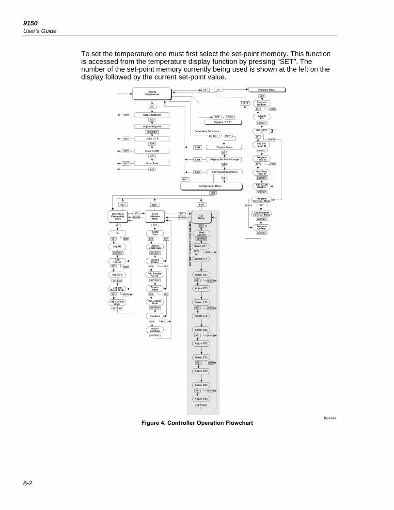
This section discusses in detail how to operate the furnace temperature controller using the front control panel. By using the front panel key-switches and LED display the user may monitor the well temperature, adjust the set-point temperature in degrees C or F, monitor the heater output power, adjust the controller proportional band, and program the probe calibration parameters, operating parameters, serial interface configuration, and controller calibration parameters. Operation of the functions and parameters are shown in the flowchart in Figure 4. This chart may be copied for reference.
In the following discussion a button with the word SET, UP, DOWN, or EXIT inside indicates the panel button while the dotted box indicates the display reading. Explanation of the button or display reading are to the right of each button or display value.
8.1 Well Temperature The digital LED display on the front panel allows direct viewing of the actual well temperature. This temperature value is what is normally shown on the dis- play. The units, C or F, of the temperature value are displayed at the right. For example,
Well temperature in degrees Celsius
The temperature displayed function may be accessed from any other function by pressing the “EXIT” button.
8.2 Temperature Set-point The temperature set-point can be set to any value within the range and resolution as given in the specifications. Be careful not to exceed the safe upper temperature limit of any device inserted into the well.
Setting the temperature involves two steps: (1) select the set-point memory and (2) adjust the set-point value.
8.2.1 Programmable Set-points The controller stores 8 set-point temperatures in memory. The set-points can be quickly recalled to conveniently set the calibrator to a previously programmed temperature set-point.
9150 User's Guide
8-2
To set the temperature one must first select the set-point memory. This function is accessed from the temperature display function by pressing “SET”. The number of the set-point memory currently being used is shown at the left on the display followed by the current set-point value.
fig-4.eps
Figure 4. Controller Operation Flowchart

Controller Operation 8.2 Temperature Set-point8
8-3
Well temperature in degrees Celsius
Access set-point memory
Set-point memory 1, 200.0°C currently used
To change the set-point memory press “UP” or “DOWN”.
New set-point memory 5, 900.0°C
Press “SET” to accept the new selection and access the set-point value.
Accept selected set-point memory
8.2.2 Set-point Value The set-point value may be adjusted after selecting the set-point memory and pressing “SET”.
Set-point value in °C
The first digit flashes on and off. If the set-point value is correct, press “EXIT” to display the temperature scale units.
If the first digit is correct press “SET”.
To adjust the first digit, press “UP” or “DOWN”. Then, press “SET” to go to the second digit. The second digit of the temperature should now be flashing. Adjust this digit by pressing “UP” or “DOWN”.
Press “SET” to accept the second digit and repeat until the last digit has been adjusted.
New set-point value
Press “SET” to accept the new set-point. If “EXIT” is pressed all changes made to the set-point are discarded.
Accept new set-point value

9150 User's Guide
8-4
8.2.3 Temperature Scale Units Temperature Scale Units of the controller are set by the user to degrees Celsius (°C) or Fahrenheit (°F). The units are used in displaying the well temperature, set-point, and proportional band.
Press “SET” after adjusting the set-point value to change display units.
=
Scale units currently selected
Press “UP” or “DOWN” to change the units.
= New units selected
Press “EXIT” to display the well temperature or press “SET” to access the scan control.
8.3 Scan The scan rate can be set and enabled so that when the set-point is changed the furnace heats or cools at a specified rate (degrees per minute) until it reaches the new set-point. With the scan disabled the furnace heats or cools at the maxi- mum possible rate.
8.3.1 Scan Control The scan is controlled with the scan on/off function that appears in the main menu after the temperature scale units.
= Scan function off
Press “UP” or “DOWN” to toggle the scan on or off.
= Scan function on
Press “SET” to accept the present setting and access the scan rate.
Accept scan setting
8.3.2 Scan Rate The next function in the main menu is the scan rate. The scan rate can be set from .1 to 99.9°C/minute. The maximum scan rate however is actually limited by the natural heating or cooling rate of the instrument. This rate is often less than 100°C/minute, especially when cooling.
The scan rate function appears in the main menu after the scan control function. The scan rate units are in degrees per minute, degrees C or F depending on the selected units.

Controller Operation 8.4 Ramp and Soak Program8
8-5
= Scan rate in °C/min.
Press “UP” or “DOWN” to change the scan rate.
= New scan rate
Press “SET” to accept the new scan rate and continue.
Accept scan rate
8.4 Ramp and Soak Program The ramp and soak program feature for the 9150 allows the user to program a number of set-points, cycle the furnace automatically between the temperatures at a scan rate set by the user, and hold the furnace at each temperature for a period of time set by the user. The user can select one of four different cycle functions. The Ramp and Soak Menu is accessed by pressing “SET” and “UP” simultaneously.
8.4.1 Program Points The 9150 contains eight “program points”. Each program point contains a set-point, scan rate, and soak time. When the unit is in program mode the unit heats or cools to the current program set-point at the current program scan rate. Once the program set-point is reached the unit waits for the program soak time before heating or cooling to the next program set-point. To access the Ramp and Soak Program Menu press “SET” and “UP” simultaneously.
Well temperature
+ Access Ramp and Soak Program Menu
Ramp and Soak Program
Press “SET” to access the number of program points.
8.4.2 Number of Program Points The first parameter in the program menu is the number of program points to cycle through. Up to 8 set-points can be used in a ramp and soak program.
= Number of program points to cycle through
Use the “UP” and “DOWN” buttons to change the program points. The valid range is from 2 to 8.
= New number of program points

9150 User's Guide
8-6
Press “SET” to continue. Pressing “EXIT” causes any changes made to the parameter to be discarded.
Accept the new number of program points.
8.4.3 Program Set-Points The controller allows the user to adjust up to eight program points. These are accessed by pressing “SET” after setting the number of program points as de- scribed in Section 8.4.2. Each program point has three associated parameters: the program set-point, the program scan rate, and the program hold (or soak) time. After adjusting the number of program points press “SET”.
Program point 1
Use the “UP” or “DOWN” buttons to select any of the program points. The controller only allows the user to edit program points that are less than or equal to the number of programs points selected as explained in Section 8.4.2. For example, if the user has selected 4 program points program points 5, 6, 7, and 8 cannot be edited.
Program point 4
Press “SET” to edit a program point.
Edit program point
The first value to edit is the program set-point.
0962.7 Program set-point value in °C
Use “UP”, “DOWN”, and “SET” to adjust the set-point as each digit flashes.
New program set-point value for program point 4
Press “SET” to save the new set-point value or “EXIT” to discard changes.
Accept the program point set-point
The next value to edit is the program soak time.
Program point 4 soak time

Controller Operation 8.4 Ramp and Soak Program8
8-7
Press “SET” to edit the program soak time.
Edit program point soak time
Current program point soak time
Use “UP”, “DOWN”, and “SET” to adjust the program soak time. This value can be any integer from 0 to 14400. This time is the minutes the program set-point maintains after the temperature of the furnace has settled and before proceeding to the next set-point. Each digit flashes individually to indicate that it can be adjusted.
Program point 4 soak time set for 200 minutes
Press “SET” to save the new soak-time value or “EXIT” to discard changes
Accept the program point soak time
The next value to edit is the program scan rate. This value is ignored if scan is not enabled for the unit (See Section 8.3.1).
Program point 4 scan rate
Press “SET” to edit the program scan rate.
Edit the program point scan rate
Current program point 4 scan rate
Use “UP” and “DOWN” to adjust the program scan rate.
New program point 4 scan rate
Press “SET” to save the new scan rate value or “EXIT” to discard changes.
Accept the program point scan rate
After “SET” is pressed the controller advances to the next program point or, if there are no more program points to edit, exits to the Program Function Menu. Repeat the above steps to edit any program point.

9150 User's Guide
8-8
8.4.4 Program Function Mode The next parameter is the program function or cycle mode. There are four possible modes which determine whether the program scans up (from set-point 1 to n) only or both up and down (from set-point n to 1), and also whether the program stops after one cycle or repeats the cycle indefinitely. The table below shows the action of each of the four program mode settings.
Function Action
1 up-stop
2 up-down-stop
3 up-repeat
4 up-down-repeat
= Program mode
Press “SET” to adjust the program mode and the “UP” or “DOWN” buttons to change the mode.
= New mode
Press “SET” to continue or “EXIT” to continue without saving the new value.
Save new setting
8.4.5 Program Control The final parameter in the program menu is the control parameter. You may choose between three options to either start the program from the beginning, continue the program from where it was when it was stopped, or stop the program.
= Program presently off
Use the “UP” or “DOWN” buttons to change the status.
= Start cycle from beginning
Press “SET” to activate the new program control command and return to the temperature display.
Activate new command.

Controller Operation 8.5 Secondary Menu8
8-9
8.5 Secondary Menu Functions which are used less often are accessed within the secondary menu. The secondary menu is accessed by pressing “SET” and “EXIT” simultaneously and then releasing. The first function in the secondary menu is the heater power display. (See Figure 4.)
8.6 Heater Power The temperature controller controls the temperature of the furnace by pulsing the heater on and off. The total power being applied to the heater is determined by the duty cycle or the ratio of heater on time to the pulse cycle time. By knowing the amount of heating the user can tell if the calibrator is heating up to the set-point, cooling down, or controlling at a constant temperature. Monitoring the percent heater power lets the user know how stable the well temperature is. With good control stability the percent heating power should not fluctuate more than ±1% within one minute.
The heater power display is accessed in the secondary menu. Press “SET” and ”EXIT” simultaneously and release. The heater power is displayed as a percent- age of full power.
Well temperature
+ Access heater power in secondary menu
Heater power in percent
To exit out of the secondary menu press “EXIT”. To continue on to the set-point voltage setting function press “SET”.
8.7 Set-point Voltage The set-point voltage is displayed for informational purposes and is used to calibrate the instrument.
The value of the set-point voltage changes when the set-point temperature is changed and also when DC1 and DC2 are adjusted.
+ Access heater power in secondary menu
Heater power in percent
Access set-point voltage
Set-point voltage in millivolts
To exit out of the secondary menu, press “EXIT”. To continue on to the proportional band setting function press “SET”.

9150 User's Guide
8-10
8.8 Proportional Band In a proportional controller such a this the heater output power is proportional to the well temperature over a limited range of temperatures around the set-point. This range of temperature is called proportional band. At the bottom of the proportional band the heater output is 100%. At the top of the proportional band the heater output is 0. Thus as the temperature rises the heater power is reduced, which consequently tends to lower the temperature back down. In this way the temperature is maintained at a fairly constant temperature.
The temperature stability of the well and response time depend on the width of the proportional band. If the band is too wide the well temperature deviates excessively from the set-point due to varying external conditions. This deviation is because the power output changes very little with temperature and the controller cannot respond very well to changing conditions or noise in the system. If the proportional band is too narrow the temperature may swing back and forth because the controller overreacts to temperature variations. For best control stability the proportional band must be set for the optimum width.
The proportional band width is set at the factory to about 30.0°C. The proportional band width may be altered by the user if he desires to optimize the control characteristics for a particular application.
The proportional band width is easily adjusted from the front panel. The width may be set to discrete values in degrees C or F depending on the selected units. The proportional band adjustment can be accessed within the secondary menu. Press “SET” and “EXIT” to enter the secondary menu and show the heater power. Then press “SET” twice to access the proportional band.
+ Access heater power in secondary menu
Heater power in percent
Access set-point voltage
Set-point voltage in millivolts
Access proportional band
Flashes ”” and then displays the setting
Proportional band
To change the proportional band, press “UP” or “DOWN.”
New proportional band setting

Controller Operation 8.9 Controller Configuration8
8-11
To store the new setting press “SET”. Press “EXIT” to continue without storing the new value.
Accept the new proportional band setting
8.9 Controller Configuration The controller has a number of configuration and operating options and calibration parameters which are programmable via the front panel. These are accessed from the secondary menu after the proportional band function by pressing “SET”. Pressing “SET” again enters the first of three groups of configuration parameters—operating parameters, serial interface parameters and calibration parameters. The groups are selected using the “UP” and “DOWN” keys and then pressing “SET”.
8.10 Operating Parameters The operating parameters menu is indicated by:
Operating parameters menu
Press “SET” to enter the menu. The operating parameters menu contains the HL (High Limit) parameter, the Soft Cutout parameter, and the Cutout Reset Mode parameter.
8.10.1 High Limit The HL parameter adjusts the upper set-point temperature. The factory default and maximum are set to 1200. For safety, a user can adjust the HL down so the maximum temperature set-point is restricted.
High Limit parameter
Press “SET” to enable adjustment of HL.
Access High Limit
Flashes the current value and then displays the value for adjustment
Current HL setting
Adjust the HL parameter digit by digit using “UP”, “DOWN”, and “SET” as each digit flashes.

9150 User's Guide
8-12
New HL setting
Press “SET” to accept the new temperature limit.
8.10.2 Soft Cutout The Soft Cutout parameter is used by the controller to shut the unit down during over-temperature conditions.
Soft Cutout parameter
Press “SET” to enable adjustments of the Soft Cutout.
Access Soft Cutout
1225 Flashes the current value and then displays the value for adjustment
1225. Current Soft Cutout setting
Adjust this parameter by using “UP”, “DOWN”, and “SET” as each digit flashes.
New Soft Cutout setting
Press “SET” to accept the new temperature limit.
If the temperature of the unit is ever greater than the Soft Cutout temperature the controller shuts itself down and displays, alternately, “SCtOut” and “Err 8”.
8.10.3 Cutout Reset Mode The cutout reset mode determines whether the cutout resets automatically when the well temperature drops to a safe value or must be manually reset by the operator.
The parameter is indicated by,
Cutout reset mode parameter
Press “SET” to access the parameter setting. Normally the cutout is set for automatic mode.
Cutout set for automatic reset

Controller Operation 8.11Serial Interface Parameters8
8-13
To change to manual reset mode press “UP” or “DOWN” and then “SET”.
Cutout set for manual reset
8.11 Serial Interface Parameters The serial RS-232 interface parameters menu is indicated by,
Serial RS-232 interface parameters menu
The serial interface parameters menu contains parameters which determine the operation of the serial interface. The parameters in the menu are: BAUD rate, sample period, duplex mode, and linefeed.
8.11.1 BAUD Rate The BAUD rate is the first parameter in the menu. The BAUD rate setting determines the serial communications transmission rate.
The BAUD rate parameter is indicated by,
Serial BAUD rate parameter
Press “SET” to choose to set the BAUD rate. The current BAUD rate value is then be displayed.
Current BAUD rate
The BAUD rate of the serial communications may be programmed to 300 600, 1200, 2400, 4800, or 9600 BAUD. 2400 BAUD is the default setting. Use “UP” or “DOWN” to change the BAUD rate value.
New BAUD rate
Press “SET” to set the BAUD rate to the new value or “EXIT” to abort the operation and skip to the next parameter in the menu.
8.11.2 Sample Period The sample period is the next parameter in the serial interface parameter menu. The sample period is the time period in seconds between temperature measurements transmitted from the serial interface. If the sample rate is set to 5, the instrument transmits the current measurement over the serial interface approximately every five seconds. The automatic sampling is disabled with a sample period of 0. The sample period is indicated by,
Serial sample period parameter

9150 User's Guide
8-14
Press “SET” to choose to set the sample period. The current sample period value is displayed.
= Current sample period (seconds)
Adjust the value with “UP” or “DOWN” and then use “SET” to set the sample rate to the displayed value.
= New sample period
8.11.3 Duplex Mode The next parameter is the duplex mode. The duplex mode may be set to full duplex or half duplex. With full duplex any commands received by the calibrator via the serial interface are immediately echoed or transmitted back to the device of origin. With half duplex the commands are executed but not echoed. The duplex mode parameter is indicated by,
Serial duplex mode parameter
Press “SET” to access the mode setting
= Current duplex mode setting
The mode may be changed using “UP” or DOWN” and pressing “SET”.
= New duplex mode setting
8.11.4 Linefeed The final parameter in the serial interface menu is the linefeed mode. This parameter enables (on) or disables (off) transmission of a linefeed character (LF, ASCII 10) after transmission of any carriage-return. The linefeed parameter is indicated by,
Serial linefeed parameter
Press “SET” to access the linefeed parameter.
= Current linefeed setting
The mode may be changed using “UP” or “DOWN” and pressing “SET”.

Controller Operation 8.12 Calibration Parameters8
8-15
= New linefeed setting
8.12 Calibration Parameters The operator of the 9150 has access to the furnace calibration constants. These values are set at the factory and must not be altered. The correct values are important to the accuracy and proper and safe operation of the furnace. Access to these parameters is available to the user only so that in the event the controller memory fails, the user may restore these values to the factory settings. The user should have a list of these constants and their settings with the manual.
Caution
DO NOT change the values of the furnace calibration constants from the factory set values. The correct settings of these parameters is important to the safety and proper operation of the furnace.
The calibration parameters menu is indicated by,
Calibration parameters menu
Press “SET” five times to enter the menu. The calibration parameters menu contains the parameters Hard Cutout, CT1, CE1, CT2, CE2, CT3, and CE3.
8.12.1 Hard Cutout This parameter is the temperature above which the unit shuts down automatically. The parameter is set at the factory to approximately 1260°C and cannot be changed by the user.
8.12.2 CT1, CT2, and CT3 The calibration parameters CT1, CT2, and CT3 are the calibration temperatures.
8.12.3 CE1, CE2, and CE3 The calibration parameters CE1, CE2 and CE3 are the calibration errors corresponding to the calibration temperatures.

9150 User's Guide
8-16
9-1
Chapter 9 Digital Communication Interface
The furnace is capable of communicating with and being controlled by other equipment through the digital serial interface.
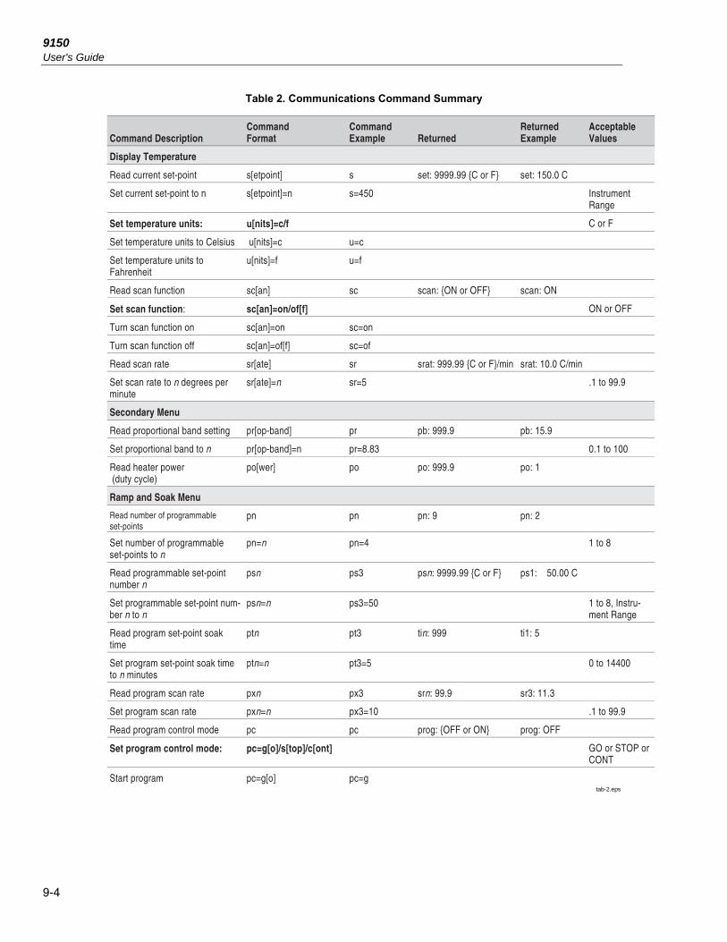
With a digital interface the instrument may be connected to a computer or other equipment. This allows the user to set the set-point temperature, monitor the temperature, and access any of the other controller functions, all using remote communications equipment. Communications commands are summarized in Table 2.
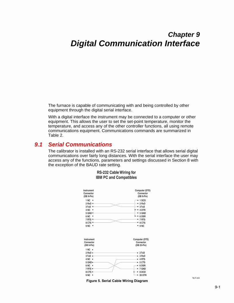
9.1 Serial Communications The calibrator is installed with an RS-232 serial interface that allows serial digital communications over fairly long distances. With the serial interface the user may access any of the functions, parameters and settings discussed in Section 8 with the exception of the BAUD rate setting.
fig-5.eps
Figure 5. Serial Cable Wiring Diagram
9150 User's Guide
9-2
9.1.1 Wiring The serial communications cable attaches to the calibrator through the DB-9 connector at the back of the instrument. Figure 5 shows the pin-out of this connector and suggested cable wiring. The serial cable should be shielded. If the unit is used in a heavy industrial setting, the serial cable must be limited to ONE meter.
9.1.2 Setup Before operation the serial interface must first be set up by programming the BAUD rate and other configuration parameters. These parameters are programmed within the serial interface menu. The serial interface parameters menu is out- lined in Figure 4 on page 22.
To enter the serial parameter programming mode first press “EXIT” while pressing “SET” and release to enter the secondary menu. Press “SET” repeatedly until the display reads “”. Press “UP” until the serial interface menu is indicated with “”. Finally press “SET” to enter the serial parameter menu. In the serial interface parameters menu are the BAUD rate, the sample rate, the duplex mode, and the linefeed parameter.
9.1.2.1 BAUD Rate The BAUD rate is the first parameter in the menu. The display prompts with the BAUD rate parameter by showing “bAUd”. Press “SET” to choose to set the BAUD rate. The current BAUD rate value is displayed. The BAUD rate of the 9150 serial communications may be programmed to 300, 600, 1200, 2400, 4800, or 9600 baud. The BAUD rate is preprogrammed to 2400 BAUD. Use “UP” or “DOWN” to change the BAUD rate value. Press “SET” to set the BAUD rate to the new value or “EXIT” to abort the operation and skip to the next parameter in the menu.
9.1.2.2 Sample Period The sample period is the next parameter in the menu and prompted with “”. The sample period is the time period in seconds between temperature measurements transmitted from the serial interface. If the sample rate is set to 5, the instrument transmits the current measurement over the serial interface approximately every five seconds. The automatic sampling is disabled with a sample period of 0. Press “SET” to choose to set the sample period. Adjust the period with “UP” or “DOWN” and then use “SET” to set the sample rate to the displayed value.
9.1.2.3 Duplex Mode The next parameter is the duplex mode indicated with “dUPL”. The duplex mode may be set to half duplex (“HALF”) or full duplex (“FULL”). With full duplex any commands received by the thermometer via the serial interface are immediately echoed or transmitted back to the device of origin. With half duplex the commands are executed but not echoed. The default setting is full duplex. The mode may be changed using “UP” or “DOWN” and pressing “SET”.
9.1.2.4 Linefeed The final parameter in the serial interface menu is the linefeed mode. This parameter enables (“On”) or disables (“OFF”) transmission of a linefeed character (LF, ASCII 10) after transmission of any carriage-return. The default setting is with linefeed on. The mode may be changed using “UP” or “DOWN” and pressing “SET”.
Digital Communication Interface 9.2 Interface Commands9
9-3
9.1.3 Serial Operation Once the cable has been attached and the interface set up properly, the controller immediately begins transmitting temperature readings at the programmed rate. The serial communications uses 8 data bits, one stop bit, and no parity.
The set-point and other commands may be sent via the serial interface to set the temperature set-point and view or program the various parameters. The inter- face commands are discussed in Section 9.2. All commands are ASCII character strings terminated with a carriage-return character (CR, ASCII 13).
9.2 Interface Commands The various commands for accessing the calibrator functions via the digital interfaces are listed in this section (see Table 2). These commands are used with the RS-232 serial interface. The commands are terminated with a carriage-re- turn character. The interface makes no distinction between upper and lower case letters, hence either may be used. Commands may be abbreviated to the minimum number of letters which determines a unique command. A command may be used to either set a parameter or display a parameter depending on whether or not a value is sent with the command following a “=” character. For example “s”<CR> returns the current set-point and “s=150.0”<CR> sets the set-point to 150.0 degrees.
9150 User's Guide
9-4
Table 2. Communications Command Summary
tab-2.eps

Digital Communication Interface 9.2 Interface Commands9
9-5
Table 3. Communications Commands Summary continued
tab-3.eps

9150 User's Guide
9-6
Table 4. Communications Commands Summary continued
tab-4.eps

10-1
Chapter 10 Test Probe Calibration
For optimum accuracy and stability, allow the calibrator to warm up for 10 minutes after power-up and then allow adequate stabilization time after reaching the set-point temperature. After completing operation of the calibrator, al- low the well to cool by setting the temperature to 150°C or less for one-half hour before switching the power off.
10.1 Calibrating a Single Probe Insert the probe to be calibrated into the well of the furnace calibrator. The probe should fit snugly into the calibrator probe sleeve yet should not be so tight that it cannot be easily removed. Avoid any dirt or grit that may cause the probe to jam into the sleeve. Best results are obtained with the probe inserted to the full depth of the well. Once the probe is inserted into the well, allow adequate stabilization time to allow the test probe temperature to settle as de- scribed above. Once the probe has settled to the temperature of the well, it may be compared to the calibrator display temperature. The display temperature should be stable to within 1°C degree for best results.
Caution
Never introduce any foreign material into the probe hole of the insert. Fluids etc. can leak into the calibrator causing damage to the calibrator or binding and damage to your probe.
10.2 Furnace Characteristics There is a temperature gradient vertically in the test well. The heater has been applied to the block in such a way as to compensate for nominal heat losses out of the top of the furnace. However, actual heat losses will vary with design of the thermometer probes inserted into the calibrator and the temperature. For best results, insert probe to full depth of well.
Caution
Do not remove inserts and insulators at high temperatures. Inserts and insulators are the same temperature as the display temperature. Use extreme care when removing hot inserts and insulators.

9150 User's Guide
10-2
10.2.1 Stabilization and Accuracy The stabilization time of the calibrator depends on the conditions and temperatures involved. Typically the test well is stable to 0.5°C within 20 minutes of reaching the set-point temperature as indicated by the display. Ultimate stability is achieved 10 to 20 minutes after reaching the set temperature.
Inserting a cold probe into a well requires another period of stabilizing depending on the magnitude of the disturbance and the required accuracy. For example, inserting a .25 inch diameter room temperature probe into a sleeve at 1200°C takes 10 minutes to be within 0.5°C of its settled point and takes 15 minutes to achieve maximum stability.
Speeding up the calibration process can be accomplished by knowing how soon to make the measurement. It is recommended that typical measurements be made at the desired temperatures with the desired test probes to establish these times.

11-1
Chapter 11 Calibration Procedure
At times the user may want to calibrate the unit to improve the temperature set-point accuracy. Calibration is done by adjusting the controller probe calibration constants CE1, CE2, and CE3 so that the temperature of the unit as measured with a standard thermocouple agrees more closely with the set-point. The thermometer used must be able to measure the well temperature with higher accuracy than the desired accuracy of the unit.
11.1 Calibration Points In calibrating the unit, CE1, CE2, and CE3 are adjusted to minimize the set-point error at each of three different well temperatures. Any three reason- ably separated temperatures may be used for the calibration. Improved results can be obtained for shorter ranges when using temperatures that are just within the most useful operating range of the unit. The farther apart the calibration temperatures, the larger the calibration range but the calibration error is also greater over the range. Choosing a range of 150°C to 500°C may allow the calibrator to have a better accuracy of maybe ±2.0°C but outside that range the ac- curacy may be greater than ±10.0°C.
11.2 Calibration Procedure 1. Choose three set-points to use in the calibration of CE1, CE2, and CE3
parameters. These set-points are generally CT1 = 150°C, CT2 = 675°C and CT3 = 1200°C but other set-points may be used if desired or necessary. Using these three temperature set-points may result in ±4.0°C accuracy.
2. If the normal set-points are not used, initialize CT1, CT2, and CT3 to the desired set points. Where CT1 is the low-set point and CT3 is the high set-point.
3. Set the unit to the low set-point. When the unit reaches the set-point and the display is stable, wait 15 minutes or so and take a reading from the thermometer. Repeat step 3 for the other two set-points recording them as Tm1, Tm2, and Tm3.

9150 User's Guide
11-2
4. Retrieve the original calibration errors from the unit or the Report of Calibration.
5. Record the previous values for CE1, CE2, and CE3 and calculate new values for CE1, CE2, and CE3 using the following formula.
Tmn –Tsn +CEn = CEm
Where:
Tmn is the temperature measured, Tsn (CTn) is the set-point temperature, CEn is the old value for calibration error, and CEm is the new value for calibration error.
6. Enter the new CEm value in the calibration parameter menu using either the keypad or through the serial port.
12-1
Chapter 12 Maintenance
• The calibration instrument has been designed with the utmost care. Ease of operation and simplicity of maintenance have been a central theme in the product development. Therefore, with proper care the instrument should require very little maintenance. Avoid operating the instrument in an oily, wet, dirty, or dusty environment.
• If the outside of the instrument becomes soiled, it may be wiped clean with a damp cloth and mild detergent. Do not use harsh chemicals on the surface which may damage the paint.
• Be sure that the well of the furnace is kept clean and clear of any foreign matter. DO NOT use fluids to clean out the well.
• If a hazardous material is split on or inside the equipment, the user is responsible for taking the appropriate decontamination steps as outlined by the national safety council with respect to the material.
• If the mains supply cord becomes damaged, replace it with a cord of the appropriate gauge wire for the current of the instrument. If there are any questions, call Hart Scientific Customer Service for more information.
• Before using any cleaning or decontamination method except those recommended by Hart, users should check with Hart Scientific Customer Service to be sure that the proposed method will not damage the equipment.
• If the instrument is used in a manner not in accordance with the equipment design, the operation of the furnace may be impaired or safety hazards may arise.
• The over-temperature cutout should be checked every 6 months to see that it is working properly.

9150 User's Guide
12-2

13-1
Chapter 13 Troubleshooting
This section contains information on troubleshooting, CE Comments, and a wiring diagram.
13.1 Troubleshooting Problems, Possible Causes, and Solutions
In the event that the instrument appears to function abnormally, this section may help to find and solve the problem. Several possible problem conditions are described along with likely causes and solutions. If a problem arises, please read this section carefully and attempt to understand and solve the problem. If the problem cannot otherwise be solved, contact Hart Scientific Customer Service for assistance (1-801-763-1600). Be sure to have the model number and serial number of your instrument available.
Problem Possible Causes and Solutions
Incorrect temperature reading
Incorrect calibration parameters. Find the values for CT1, CT2, CT3, CE1, CE2, and CE3 on the Report of Calibration that was shipped with the instrument (or from subsequent calibrations of the instrument). Reprogram the parameters into the Model 9150 memory (see Section 8.12, Calibration Parameters). Allow the instrument to stabilize and verify the accuracy of the temperature reading.
Memory scrambled. The memory may be scrambled due to a power surge or other aberration. Initialize the system by performing the Factory Reset Sequence.
Factory Reset Sequence. Hold the SET and EXIT buttons down at the same time while powering up the instrument. After the instrument displays , release the buttons. The display shows 9150, and then displays the firmware version. After performing the master reset sequence, all of the configuration parameters are reset to their default values. Reprogram the calibration parameters into the Model 9150 memory (see Section 8.12, Calibration Parameters) and any other applicable configuration parameters. Allow the instrument to stabilize and verify the accuracy of the temperature reading.

9150 User's Guide
13-2
The instrument heats or cools too quickly or too slowly
Incorrect scan and scan rate settings. The scan and scan rate settings may be set to unwanted values. Check the Scan and Scan Rate settings. The scan may be off (if the unit seems to be responding too quickly). The scan may be on with the Scan Rate set low (if unit seems to be responding too slowly).
Incorrect heater switch polarity. The PEM and the heater voltage switch may not be set for the same voltage. Check both settings and correct as needed.
The display shows any of the following:
, , ,, , ,, or
Controller problem. The error messages signify the following problems with the controller.
- a RAM error
- a NVRAM error
- a RAM error
- an ADC setup error
- an ADC ready error
– a Sensor error
– a Heater control error
– a Soft cutout error
Initialize the system by performing the Factory Reset Sequence describe above.
Temperature cannot be set above a certain point
Incorrect High Limit parameter. The High Limit parameter may be set below 1200°C. Check this value as described in Section 8.10, Operating Parameters.
The display flashes
Incorrect Soft Cutout parameter. Wait for the instrument to cool and adjust the Soft Cutout parameter as described in Section 8.10, Operating Parameters.
13.2 Comments 13.2.1 EMC Directive
Equipment manufactured by Hart Scientific has been tested to meet the European Electromagnetic Compatibility Directive (EMC Directive, 89/336/EEC). The Declaration of Conformity for your instrument lists the specific standards to which the unit was tested.
13.2.2 Low Voltage Directive (Safety) In order to comply with the European Low Voltage Directive (73/23/EEC), Hart Scientific equipment has been designed to meet the IEC 1010-1 (EN 61010-1) and the IEC 1010-2-010 (EN 61010-2-010) standards.