user's guide for ecg-ug-02-002 page: 36/98 30gx&hx pro … carrier/user guide 30hx...
TRANSCRIPT
4.3 - Cooler Interlock contact
A contact to check the status of a safety loop is provided (cooler flow switch and customer interlock are wiredinternally in series). Its function is to prevent the unit from starting if the contact is open while the delay at startup hasexpired. The contact must also stay closed as long as the unit is not stopped through Local, Remote or CCN control.
If the cooler pump is controlled by the pro-dialog and if the cooler contact is closed after 2 minutes the cooler pumpis turned OFF provided that the contact is failed CLOSED, the alarm 75 shall be active and the unit can't no morestart until manual reset.
4.4 - Cooler heater control
This function is applied only for air cooled units and is related to the cooler pump function when the unit state is OFFor when unit operates as a lag chiller in master/slave operation and in standby mode. This is provided on outdoorunit as a safeguard against the cooler freezing. The cooler heater is associated with refrigerant isolation solenoids,one output per circuit whose goal is to prevent the refrigerant from migrating into the condenser when chiller isstopped.
The following logic shall be used:
w If the outdoor air temperature is below the cooler heater trip point and if either the saturated suction temperatureof circuit A or saturated suction temperature of circuit B are lower than the cooler heater trip point plus 3.3 ^C,the cooler heater shall be activated.
w Normally the isolation valves shall prevent refrigerant in the cooler from migrating into the condenser. For thiscase, cooler heater can ensure cooler protection efficiently without the need of using cooler pump.
w If it is not the case (SST remain low), the pump shall be turned on every 7 minutes to check freezing conditionsand additional heat to the cooler : cooler fluid temp (< 3° - [SSTa + SSTb]/2). Pump shall be turned of if coolerfluid temp > (8°C - [SSTa + SSTb]/2).
w If both saturated suction temperatures of circuit A and circuit B are greater than the cooler heater trip point plus5.5 ^C, the cooler heater shall be turned off. The pump shall be allowed to stop.
heater trip point = freeze + heat_spt (heat_sp from SERVICE2 table)freeze = 1.1 for water, coldest setpoint - 4.4^C for brine
4.5 - Oil heater control
Each circuit has its own oil separator fitted with an oil heater. Both circuit oil heater are controlled independently .Since there is no oil temperature sensor, the oil heater will be controlled based on the saturated condensingtemperature as follows :
wOil heater ON when outside temperature is below 17°C.wOil heater OFF when outside temperature is above 25°CwOil heater OFF when circuit is in operation or oil level is low (oil_sw is OPEN).
4.6 - Motor Cooling Control without plate exchanger economizer
The screw compressor motors used in the Global Chiller control are refrigerant cooled. The control strategy for motorcooling relies on vapor at light loads, and supplementary liquid refrigerant at high loads. Each compressor will haveits own cooling solenoid. An additional motor cooling solenoid is required when operating in high condensingtemperature. It is automatically controlled by pro-dialog even if it is not mounted in the units. The motor coolingsolenoids shall be cycled to allow liquid to cool the motor. The main motor cooling solenoid control is based on themotor temperature and its setpoint (83°C) using a quasi-fuzzy logic. The additional motor cooling solenoid control isjust based on the discharge gas temperature.
CARRIER SAUSER'S GUIDE FOR
30GX&HX PRO_DIALOG 4 V.2ECG-UG-02-002
Rev: OriginalPage: 36/98
© CARRIER S.ANOT TO BE DISCLOSED TO PERSONS OUTSIDE CARRIER ORGANIZATION
4.7 - Motor Cooling Control with sub cooling plate exchanger
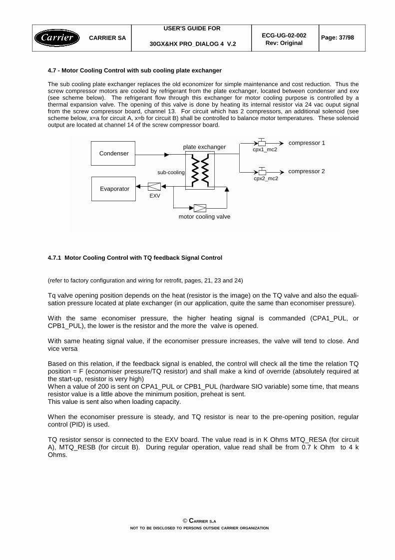
The sub cooling plate exchanger replaces the old economizer for simple maintenance and cost reduction. Thus thescrew compressor motors are cooled by refrigerant from the plate exchanger, located between condenser and exv(see scheme below). The refrigerant flow through this exchanger for motor cooling purpose is controlled by athermal expansion valve. The opening of this valve is done by heating its internal resistor via 24 vac ouput signalfrom the screw compressor board, channel 13. For circuit which has 2 compressors, an additional solenoid (seescheme below, x=a for circuit A, x=b for circuit B) shall be controlled to balance motor temperatures. These solenoidoutput are located at channel 14 of the screw compressor board.
Evaporator
Condenser
EXV
motor cooling valve
sub-cooling
plate exchanger compressor 1
compressor 2
cpx1_mc2
cpx2_mc2
4.7.1 Motor Cooling Control with TQ feedback Signal Control
(refer to factory configuration and wiring for retrofit, pages, 21, 23 and 24)
Tq valve opening position depends on the heat (resistor is the image) on the TQ valve and also the equali-sation pressure located at plate exchanger (in our application, quite the same than economiser pressure).
With the same economiser pressure, the higher heating signal is commanded (CPA1_PUL, orCPB1_PUL), the lower is the resistor and the more the valve is opened.
With same heating signal value, if the economiser pressure increases, the valve will tend to close. Andvice versa
Based on this relation, if the feedback signal is enabled, the control will check all the time the relation TQposition = F (economiser pressure/TQ resistor) and shall make a kind of override (absolutely required atthe start-up, resistor is very high)When a value of 200 is sent on CPA1_PUL or CPB1_PUL (hardware SIO variable) some time, that meansresistor value is a little above the minimum position, preheat is sent.This value is sent also when loading capacity.
When the economiser pressure is steady, and TQ resistor is near to the pre-opening position, regularcontrol (PID) is used.
TQ resistor sensor is connected to the EXV board. The value read is in K Ohms MTQ_RESA (for circuitA), MTQ_RESB (for circuit B). During regular operation, value read shall be from 0.7 k Ohm to 4 kOhms.
CARRIER SAUSER'S GUIDE FOR
30GX&HX PRO_DIALOG 4 V.2ECG-UG-02-002
Rev: OriginalPage: 37/98
© CARRIER S.ANOT TO BE DISCLOSED TO PERSONS OUTSIDE CARRIER ORGANIZATION
4.8 - CAPACITY CONTROL
This function adjusts the number of active compressors and loaders to keep the leaving water temperature at thesetpoint. The precision with which this is achieved depends upon the capacity of the water loop, the water flowrate, the load and the number of capacity control steps available. The control continuously takes account of thetemperature error with respect to the control point, the rate of change of the leaving fluid temperature and the deltaof temperatures between the entering and leaving fluid in order to determine the optimum time to add or subtractsteps of capacity.
Note: a too important number of starts of a particular compressor will automatically cause a limitation of thecompressors starts. This will affect the precision of the water loop temperature control.
4.8.1 - Logic description
4.8.1.1 - Basic logic
To operate the capacity control task uses the following inputs:w EWT Entering water temperaturew LWT Leaving water temperaturew CTRL_PNT Control pointw Cooling z_multiplier Z Multiplier (range: 1.0 to 6.0)w Heating z_multiplier Z Multiplier (range: 1.0 to 6.0)
The control calculates the SMZ: load/unload factor. It is compared to the z_multiplier to determine when to add orremove stage:
w If (sum/z) > +z_multiplier -> stage = +1 (add a compressor)w If (sum/z) > +0.6 and if a loader is available (loader is OFF) -> stage = +1 (add a loader)w If (sum/z) < - z_multiplier -> stage = -1 (remove one compressor)w If sum/z) < -0.6 and loader is avaialble (loader is ON) -> stage = -1 (turn off one loader)
Note: z_multiplier doesn't apply to loaders.
4.8.1.2 - Z Multiplier calculation
The z_multiplier factor allows to indirectly increase the compressor on/off time delay. In consequence, it can beadjusted (increased) to avoid compressors short cycling. This function requires the following Service configuration:
vAuto Z Multiplier sepoint (zm_spt). Default to 6.vCooling and heating Z Multiplier max value (hc_zm). default to 6.0.
This function adapts the z_multiplier to the unit compressor cycles number (the cycle number shall be based onthe compressor which has been the most started during an hour). The significant period for compressors cyclingshall be of one hour.
If the cycle counter exceeds the setpoint (zm_spt), then the z_multiplier value shall be increased based on thecycle number (PID loop). The function shall not take care of the loaders cycling.
The calculated value of the z_multiplier shall not exceed the configured hc_zm. If the unit returns to normal operating condition with a cycles counter going down then the calculated z_multipliershall progressively return to its normal value (zm = 1.0). The rate at which the calculated z_multiplier returns tonormal shall be lower than the rate at which it is increased.
The setpoint value shall allow to adapt the auto z multiplier calculation to the installation. The setpoint rangesfrom 4 to 6.
During normal operation, each modification of the unit capacity is followed by a dead time when no capacitymodification is possible. The duration of this dead time is 90 seconds.
4.8.1.3 - Overrides
CARRIER SAUSER'S GUIDE FOR
30GX&HX PRO_DIALOG 4 V.2ECG-UG-02-002
Rev: OriginalPage: 38/98
© CARRIER S.ANOT TO BE DISCLOSED TO PERSONS OUTSIDE CARRIER ORGANIZATION

sum/z ratio will be overridden if any one of the following conditions is satisfied.
1 Cooler freeze protection2,3 Very Low saturated suction temperature4 Low source temperature protection5,6 Low discharge superheat temperature7, 8 Low temperature Cooling/High temperature heating9 Demand limit10 Cooler Lock11 Slow change override12 Ramp loading13 Minimum ON/OFF delay14 High temperature cooling and low temperature heating15 System Manager control16, 17 High pressure18,19 High current20, 21 Low saturated suction temperature22,23,24,25 High condensing temperature28 Compressor startup with loader 1 on due to low condensing temperature26, 27 Low Oil Level when circuit is OFF29,30 Stopping circuit due to low oil level (allowed thrice within 2 hours) before going to alarm31,32 High motor temperature on economizer units (T° > 93°C) 33,34 Stopping compressor due high motor temperature (T° > 110°C, allowed thrice within 2 hours)
before going to alarm35 Chiller current limit
Note : When overrides 2,3 , 5, 6, 16, 17, 18, 19, 20, 21 are active, the variable close control (cls_ctrl) shall beenabled whatever the configuration to allow unloading the last loader in the circuit.
Chiller Current Override (override #35)
This function allows customer to limit the total current (it does not include current of fans, valves, heaters, oil pumps...) of all the compressors during operation. The chiller current limit can be modified through USER configuration(USER table or User configuration by main interface). This function is similar to demand limit function.
wIf the chiller current is greater than the chiller current limit , then a stage of capacity will be removed.wIf chiller current plus the added current of selected compressor is greater than the chiller current limit, the
increase of capacity will not be allowed. If the compressors is OFF, its added current is 80% of its MTA. If theselected compressor is on but deos not reach 100% capacity, an added stage on the same compressor will add40% of its current.
CARRIER SAUSER'S GUIDE FOR
30GX&HX PRO_DIALOG 4 V.2ECG-UG-02-002
Rev: OriginalPage: 39/98
© CARRIER S.ANOT TO BE DISCLOSED TO PERSONS OUTSIDE CARRIER ORGANIZATION
4.9 - COMPRESSORS & LOADERS LOADING SEQUENCE
4.9.1 - General Description
The Global chillers uses compressors which have better performance at full load than at part load. Therefore, theloading sequence strategy will be different than for the flotronic II or for the Pro-dialog 30 G & H. The following list applies only to capacity control. For High Ambient Unloading, it can be overridden.
1. A compressor will not be started until all other running compressors are 100% loaded.
2. On units with 3 compressors, both circuits cannot have their loaders off at the same time once 3 ormore of the compressors in the unit are on. Where possible, the circuit which is starting acompressor will be the one which is to be unloaded.
3. Any time a lag compressor in a circuit is starting, the loaders in the circuit shall be turned off(unloading all compressors in the circuit). This shall be done 15 seconds prior to starting the newcompressor. 15 seconds after the new compressor has started, the loaders shall be set to theirdesired state. When a lead compressor is starting, all loaders shall be turned off when thecompressor relay is turned on (+/- 2 seconds), and shall be set to their desired state 15 secondsafter the compressor has been started.
4. There shall be a configuration decision for "close control", which (when selected) will cause thecontrol to utilize all of the loading devices to achieve better leaving water temperature control.
5. Whenever any compressor in a circuit is going to be stopped normally, the circuit shall be fullyunloaded for 15 seconds prior to shutting down the compressor. This shall not apply when thereason for a shutdown is due to an alarm condition.
7. For any shutdown, all compressors and loaders will be shut down at the same time.
For more than 2 compressors, two types of sequencing are available and configurable by the user through either theMain Interface or through the CCN network:
w Equal circuit loading: The control shall attempt to maintain equal capacity between the circuits as the machineloads and unloads.
w Staged circuit loading: The control shall load the lead circuit completely before the lag circuit is started. Whenthe load is decreasing the lag circuit shall be unloaded first.
Circuit compressors sequence select shall try to equalize the compressor starts number. That means anycompressor in the circuit can become the lead compressor if it has the lowest starts number, however, this shall bebalanced with the operating hours.
Loaders in the same circuit are commanded simultaneously. Thus one loader variable is displayed.
When a circuit is overridden (compressor status are blinking in the synopsis) because of low suctiontemperature, low or high discharge temperature or high condensing temperature (high pressure), or highcurrent then no capacity increase shall be allowed on the affected circuit. This circuit is selected to unloadcapacity first when unloading capacity condition is required.
4.9.2- Compressor capacity determination
Each compressor has three stages capacity. Simulation had been done to determine the average capacitycorresponding to those stages as following :
No loader ON -> 40%Only loader_1 -> 70%Both loaders ON -> = 100%
CARRIER SAUSER'S GUIDE FOR
30GX&HX PRO_DIALOG 4 V.2ECG-UG-02-002
Rev: OriginalPage: 40/98
© CARRIER S.ANOT TO BE DISCLOSED TO PERSONS OUTSIDE CARRIER ORGANIZATION
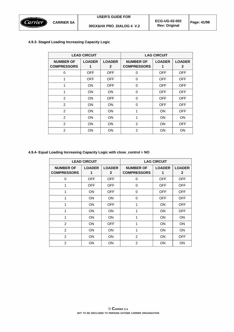
4.9.3- Staged Loading Increasing Capacity Logic
ONON2ONON2
OFFON2ONON2
ONON1ONON2
OFFON1ONON2
OFFOFF0ONON2
OFFOFF0OFFON2
OFFOFF0ONON1
OFFOFF0OFFON1
OFFOFF0OFFOFF1
OFFOFF0OFFOFF0
LOADER2
LOADER1
NUMBER OFCOMPRESSORS
LOADER2
LOADER1
NUMBER OFCOMPRESSORS
LAG CIRCUIT LEAD CIRCUIT
4.9.4- Equal Loading Increasing Capacity Logic with close_control = NO
ONON2ONON2
OFFON2ONON2
ONON1ONON2
ONON1OFFON2
ONON1ONON1
OFFON1ONON1
OFFON1OFFON1
OFFOFF0ONON1
OFFOFF0OFFON1
OFFOFF0OFFOFF1
OFFOFF0OFFOFF0
LOADER2
LOADER1
NUMBER OFCOMPRESSORS
LOADER2
LOADER1
NUMBER OFCOMPRESSORS
LAG CIRCUIT LEAD CIRCUIT
CARRIER SAUSER'S GUIDE FOR
30GX&HX PRO_DIALOG 4 V.2ECG-UG-02-002
Rev: OriginalPage: 41/98
© CARRIER S.ANOT TO BE DISCLOSED TO PERSONS OUTSIDE CARRIER ORGANIZATION
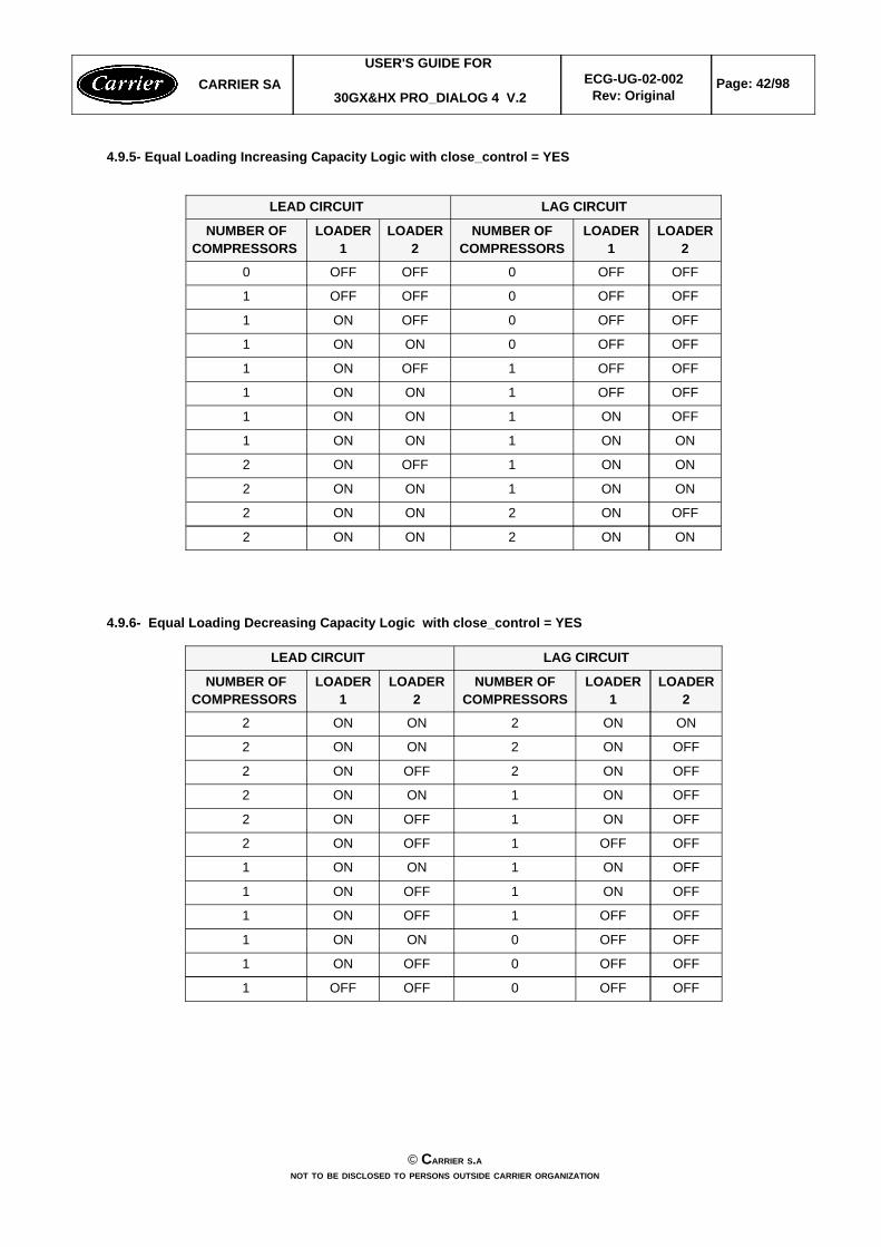
4.9.5- Equal Loading Increasing Capacity Logic with close_control = YES
ONON2ONON2
OFFON2ONON2
ONON1ONON2
ONON1OFFON2
ONON1ONON1
OFFON1ONON1
OFFOFF1ONON1
OFFOFF1OFFON1
OFFOFF0ONON1
OFFOFF0OFFON1
OFFOFF0OFFOFF1
OFFOFF0OFFOFF0
LOADER2
LOADER1
NUMBER OFCOMPRESSORS
LOADER2
LOADER1
NUMBER OFCOMPRESSORS
LAG CIRCUIT LEAD CIRCUIT
4.9.6- Equal Loading Decreasing Capacity Logic with close_control = YES
OFFOFF0OFFOFF1
OFFOFF0OFFON1
OFFOFF0ONON1
OFFOFF1OFFON1
OFFON1OFFON1
OFFON1ONON1
OFFOFF1OFFON2
OFFON1OFFON2
OFFON1ONON2
OFFON2OFFON2
OFFON2ONON2
ONON2ONON2
LOADER2
LOADER1
NUMBER OFCOMPRESSORS
LOADER2
LOADER1
NUMBER OFCOMPRESSORS
LAG CIRCUIT LEAD CIRCUIT
CARRIER SAUSER'S GUIDE FOR
30GX&HX PRO_DIALOG 4 V.2ECG-UG-02-002
Rev: OriginalPage: 42/98
© CARRIER S.ANOT TO BE DISCLOSED TO PERSONS OUTSIDE CARRIER ORGANIZATION
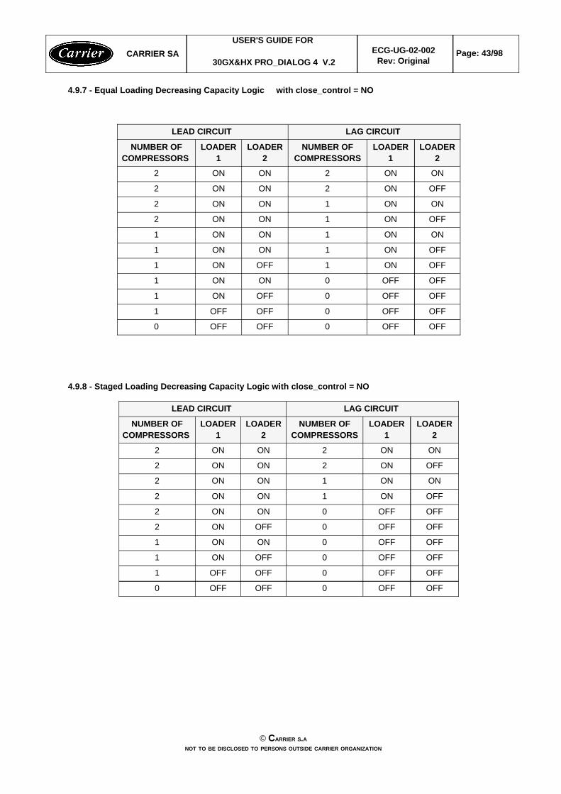
4.9.7 - Equal Loading Decreasing Capacity Logic with close_control = NO
OFFOFF0OFFOFF0
OFFOFF0OFFOFF1
OFFOFF0OFFON1
OFFOFF0ONON1
OFFON1OFFON1
OFFON1ONON1
ONON1ONON1
OFFON1ONON2
ONON1ONON2
OFFON2ONON2
ONON2ONON2
LOADER2
LOADER1
NUMBER OFCOMPRESSORS
LOADER2
LOADER1
NUMBER OFCOMPRESSORS
LAG CIRCUIT LEAD CIRCUIT
4.9.8 - Staged Loading Decreasing Capacity Logic with close_control = NO
OFFOFF0OFFOFF0
OFFOFF0OFFOFF1
OFFOFF0OFFON1
OFFOFF0ONON1
OFFOFF0OFFON2
OFFOFF0ONON2
OFFON1ONON2
ONON1ONON2
OFFON2ONON2
ONON2ONON2
LOADER2
LOADER1
NUMBER OFCOMPRESSORS
LOADER2
LOADER1
NUMBER OFCOMPRESSORS
LAG CIRCUIT LEAD CIRCUIT
CARRIER SAUSER'S GUIDE FOR
30GX&HX PRO_DIALOG 4 V.2ECG-UG-02-002
Rev: OriginalPage: 43/98
© CARRIER S.ANOT TO BE DISCLOSED TO PERSONS OUTSIDE CARRIER ORGANIZATION
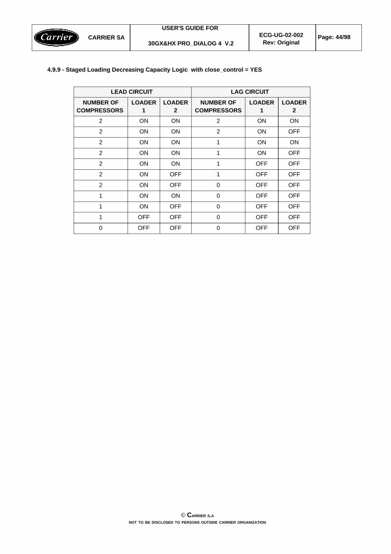
4.9.9 - Staged Loading Decreasing Capacity Logic with close_control = YES
OFFOFF0OFFOFF0
OFFOFF0OFFOFF1
OFFOFF0OFFON1
OFFOFF0ONON1
OFFOFF0OFFON2
OFFOFF1OFFON2
OFFOFF1ONON2
OFFON1ONON2
ONON1ONON2
OFFON2ONON2
ONON2ONON2
LOADER2
LOADER1
NUMBER OFCOMPRESSORS
LOADER2
LOADER1
NUMBER OFCOMPRESSORS
LAG CIRCUIT LEAD CIRCUIT
CARRIER SAUSER'S GUIDE FOR
30GX&HX PRO_DIALOG 4 V.2ECG-UG-02-002
Rev: OriginalPage: 44/98
© CARRIER S.ANOT TO BE DISCLOSED TO PERSONS OUTSIDE CARRIER ORGANIZATION
4.10 - EXV CONTROL
4.10.1 - General
The EXV is controlled to maintain minimum pinch for insuring the cooler exchange performance through the deltatemperature between the cooler fluid and the saturated suction temperature. EXV opening movement will normallydecrease the cooler pinch and thus increase the cooler exchange performance. But it shall not open too muchprovided a drop in discharge superheat , low oil pressure and refrigerant flow.
The EXV control shall deal with two goals : Smaller Cooler Pinch and Discharge Superheat Protection.
Additional protection against excessive EXV opening is applied to ensure the condenser heat transfer (sub cooling).It may happen when operating in high condensing temperature and indirectly high discharge superheat, exv wouldtend to open continuously to get the lower pinch due to the setpoint and unfortunately in certain conditions, this valuehas reached the limit, though it is higher than the setpoint. Therefore, EXV position limit shall be set when there isno more variation in cooler pinch for a variation of EXV position of 4 percent.
EXV position shall also be limited to avoid hunting problem due to low discharge superheat protection. It may occurwhen operating in a low condensing temperature, the discharge superheat protection can switch from enable todisable in few scans and so on.
This control uses a kind of auto adaptive method whose goal is to find out the optimal position of EXV for insuring anoptimal pinch with a correct discharge superheat and sub cooling.
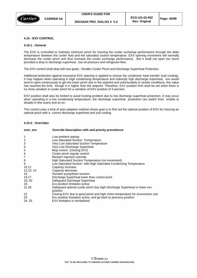
4.10.2 - Overrides
over_exv Override Description with and priority precedence.
1 Low ambient startup 2 Low Saturated Suction Temperature3 Very Low Saturated Suction Temperature4 Very Low Discharge Superheat5 Mop control (Closing EXV)6 Cooler pinch regular control7 Reclaim injection override8 High Saturated Suction Temperature (no movement)9 Low Saturated Suction with High Saturated Condensing Temperature10,11 Capacity increase12,13, 14 Capacity decrease15 Reclaim pumpdown session16,17 Discharge Superheat lower than control point18, 20 Safeguard Discharge Superheat 19 Exv position limitation active21,26 Safeguard optimal cooler pinch due high Discharge Superheat or lower exv
position22 Closing EXV due to good pinch and high motor temperature for economizer unit 23 Exv position limitation active, and go back to previous position24, 25 EXV limitation is reinitialized
CARRIER SAUSER'S GUIDE FOR
30GX&HX PRO_DIALOG 4 V.2ECG-UG-02-002
Rev: OriginalPage: 45/98
© CARRIER S.ANOT TO BE DISCLOSED TO PERSONS OUTSIDE CARRIER ORGANIZATION
4.11 - Air Cooled Condensing Pressure Control
Head pressure differential value and head pressure differential timer can be adjusted in the Service menu.Decreasing these values will increase fan cycling. This differential value and timer can be reduced since the unit isfitted with an important number of fan stages, as to increase the condensing control accuracy. But in certain cases,notably on units with few fan stages, at too small value can causes superheat hunting problems.Varifan PID gains can be modified in the Service menu (not recommended). See section 4.2.3.
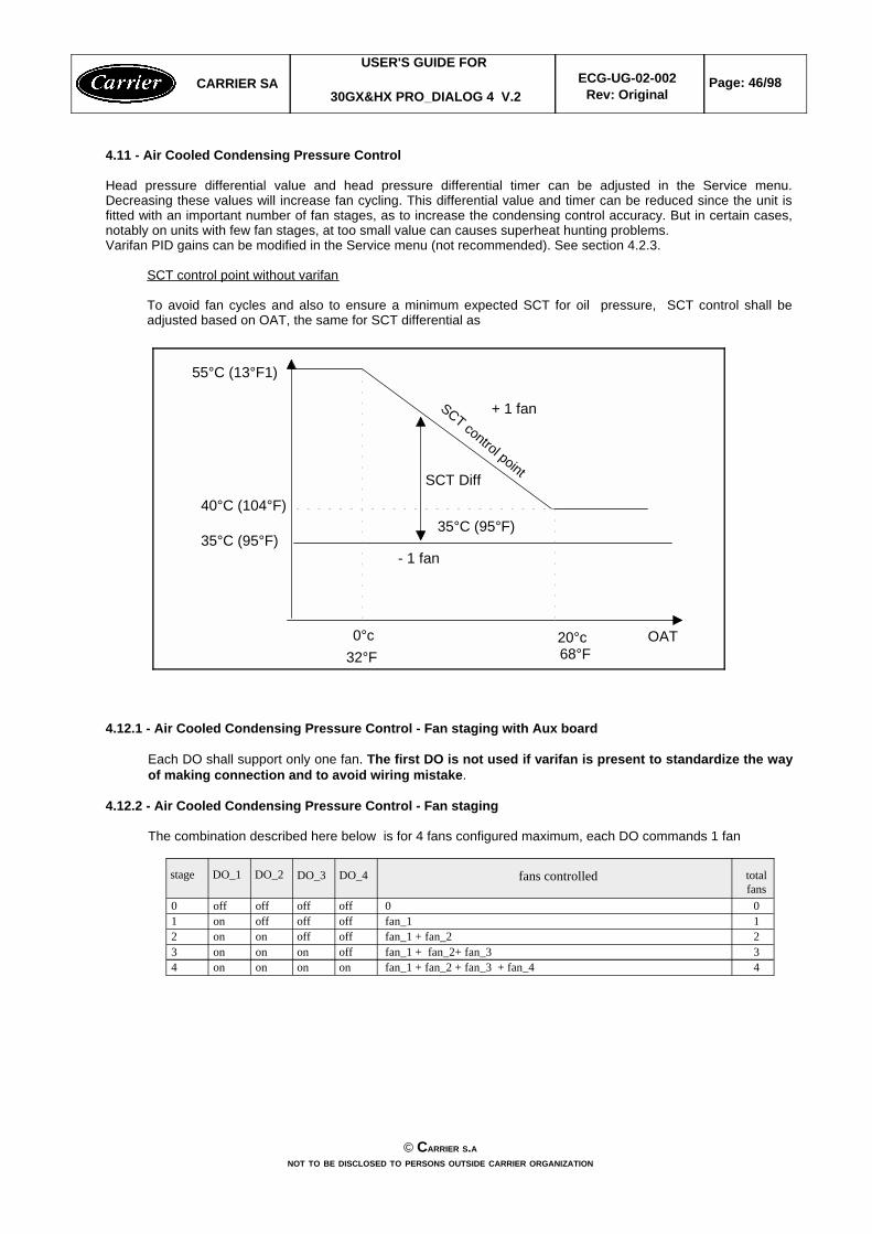
SCT control point without varifan
To avoid fan cycles and also to ensure a minimum expected SCT for oil pressure, SCT control shall beadjusted based on OAT, the same for SCT differential as
55°C (13°F1)
OAT20°c0°c68°F32°F
+ 1 fan
- 1 fan
SCT control point
35°C (95°F)
40°C (104°F)35°C (95°F)
SCT Diff
4.12.1 - Air Cooled Condensing Pressure Control - Fan staging with Aux board
Each DO shall support only one fan. The first DO is not used if varifan is present to standardize the wayof making connection and to avoid wiring mistake.
4.12.2 - Air Cooled Condensing Pressure Control - Fan staging
The combination described here below is for 4 fans configured maximum, each DO commands 1 fan
4fan_1 + fan_2 + fan_3 + fan_4onononon43fan_1 + fan_2+ fan_3 offononon32fan_1 + fan_2offoffonon21fan_1offoffoffon100offoffoffoff0
totalfans
fans controlledDO_4DO_3DO_2DO_1stage
CARRIER SAUSER'S GUIDE FOR
30GX&HX PRO_DIALOG 4 V.2ECG-UG-02-002
Rev: OriginalPage: 46/98
© CARRIER S.ANOT TO BE DISCLOSED TO PERSONS OUTSIDE CARRIER ORGANIZATION

The following combinations are used for a circuit with more than 4 fans configured
5fan_1 + fan_2 + fan_3 + fan_4 + fan_5onononon54fan_1 + fan_2 + fan_3 + fan_4offononon43fan_1 + - + fan_3 + fan_4offonoffon32fan_1 + fan_2offoffonon21fan_1offoffoffon100offoffoffoff0
total fans
fans controlledDO_4DO_3DO_2DO_1stage
6fan_1+ fan_2 + fan_3 + fan_4 + fan_5 + fan_6onononon65fan_1+ - + fan_3 + fan_4+ fan_5 + fan_6 ononoffon54fan_1+ fan_2 + fan_3 + fan_4offononon43fan_1+ - + fan_3 + fan_4offonoffon32fan_1+ fan_2offoffonon21fan_1offoffoffon10-offoffoffoff0
total fans
fans controlledDO_4DO_3DO_2DO_1stage
7fan_1 + fan_2 + fan_3 + fan_4 + fan_5 + fan_6 + fan_7onononon76fan_1 + - + fan_3 + fan_4 + fan_5 + fan_6 + fan_7ononoffon65fan_1 + fan_2 + - + - + fan_5 + fan_6 + fan_7 onoffonon54fan_1 + fan_2 + fan_3 + fan_4offononon43fan_1 + - + fan_3 + fan_4offonoffon32fan_1 + fan_2offoffonon21fan_1offoffoffon10-offoffoffoff0
total fans
fans controlledDO_4DO_3DO_2DO_1stage
8fan_1 + fan_2 + fan_3 + fan_4 + fan_5 + fan_6 + fan_7 + fan_8onononon87fan_1 + - + fan_3 + fan_4 + fan_5 + fan_6 + fan_7 + fan_8ononoffon76fan_1 + fan_2 + - + - + fan_5 + fan_6 + fan_7 + fan_8onoffonon65fan_1 + - + - + - + fan_5 + fan_6 + fan_7 + fan_8onoffoffon54fan_1 + fan_2 + fan_3 + fan_4offononon43fan_1 + - + fan_3 + fan_4offonoffon32fan_1 + fan_2offoffonon21fan_1offoffoffon10-offoffoffoff0
total fans
fans controlledDO_4DO_3DO_2DO_1stage
4.13 - Water Cooled Condensing Pressure Control
The control of a common water valve for both circuits is required. The water valve control will be based on thehighest saturated condensing temperature of both circuit or based on the operating circuit if the other is OFF.
Water valve PID gains can be modified in the Service menu (when unit is OFF). See section 4.2.3. They areaccessible though the table SERVICE1 and can be modified during operation.
CARRIER SAUSER'S GUIDE FOR
30GX&HX PRO_DIALOG 4 V.2ECG-UG-02-002
Rev: OriginalPage: 47/98
© CARRIER S.ANOT TO BE DISCLOSED TO PERSONS OUTSIDE CARRIER ORGANIZATION
4.14 - High Pressure (Maximum Condensing Temperature) Override
This function shall be used to avoid circuit high pressure trip while the condensing pressure reaches a configurableoverride threshold (Service 1 Configuration).
wIf the saturated condensing temperature is greater than the maximum condensing temperature (mct_sp) minusthe maximum condensing temperature override differential (mct_diff) but less than the maximum condensingtemperature (mct_sp) then the circuit capacity increase shall be inhibited.
wIf the saturated condensing temperature is greater than the maximum condensing temperature (mct_sp) then thecircuit capacity shall be reduced. The first capacity stage shall never be turned off even if that causes a circuithigh pressure trip.
wIf the circuit capacity has been reduced due to high condensing temperature override then the circuit capacityincrease will not be allowed for 5 minutes even if the saturated condensing temperature is below the maximumcondensing temperature (mct_sp) minus the maximum condensing temperature override differential. This shallavoid compressor cycling.
4.15 - High Current Override
This function shall be used to avoid circuit high current trip while the motor current reaches a configurable overridethreshold (Service 1 Configuration).
wIf the current is greater than the maximum current threshold (curr_max) minus the maximum current overridedifferential (curr_diff) but less than the maximum current threshold (curr_max) then the circuit capacity increaseshall be inhibited.
wIf the current is greater than the maximum current threshold (curr_max) then the circuit capacity shall be reducedby removing a loader or the affected compressor.
wIf the circuit capacity has been reduced due to current override then the circuit capacity increase will not beallowed for 5 minutes what ever current measured. This shall avoid compressor cycling.
4.16 - Stopping Function
4.16.1- Stopping a compressor by capacity unloading
If the selected compressor is operating with at least one loader ON, then all the loaders in the same circuit shall bede-energized for 15 seconds before stopping the compressor.
4.16.2- Stopping the unit by manual command (OFF)
Both circuit shall decrease its capacity progressively every 15 seconds. One loader is immediately de-energized. Thelast loader will be de-energized in 15 seconds later. Then all compressors, oil solenoids and oil pump will bede-energized in 15 seconds after the last loader is turned OFF.Here is an example of the stopping function with time indicator for a circuit with both loaders ON before receiving aSTOP command. t = t0 loader_2 = OFF t = t0 + 15s loader_1 = OFF, t = t0 + 30s All the compressors, oil solenoids and oil pumps shall be de-energized
The exv shall be closed in one minute after the last compressor is de-energized or after the difference between discharge and suction pressure is lower than 58 psi
note : Both circuits can be stopped in different timing depending on the status of their loaders when theSTOP command is received. Maximum duration for stopping the unit is 30 seconds. A circuit can be stoppedimmediately if no loader is ON before going to stopping procedure.
4.16.3- Stopping a circuit by failure
If the circuit or the hole unit are failed by alarms freeze, low sst, cooler flow, all the compressors are shut offimmediately. Otherwise, it shall respect procedure above.
CARRIER SAUSER'S GUIDE FOR
30GX&HX PRO_DIALOG 4 V.2ECG-UG-02-002
Rev: OriginalPage: 48/98
© CARRIER S.ANOT TO BE DISCLOSED TO PERSONS OUTSIDE CARRIER ORGANIZATION
4.17- Oil pressure control
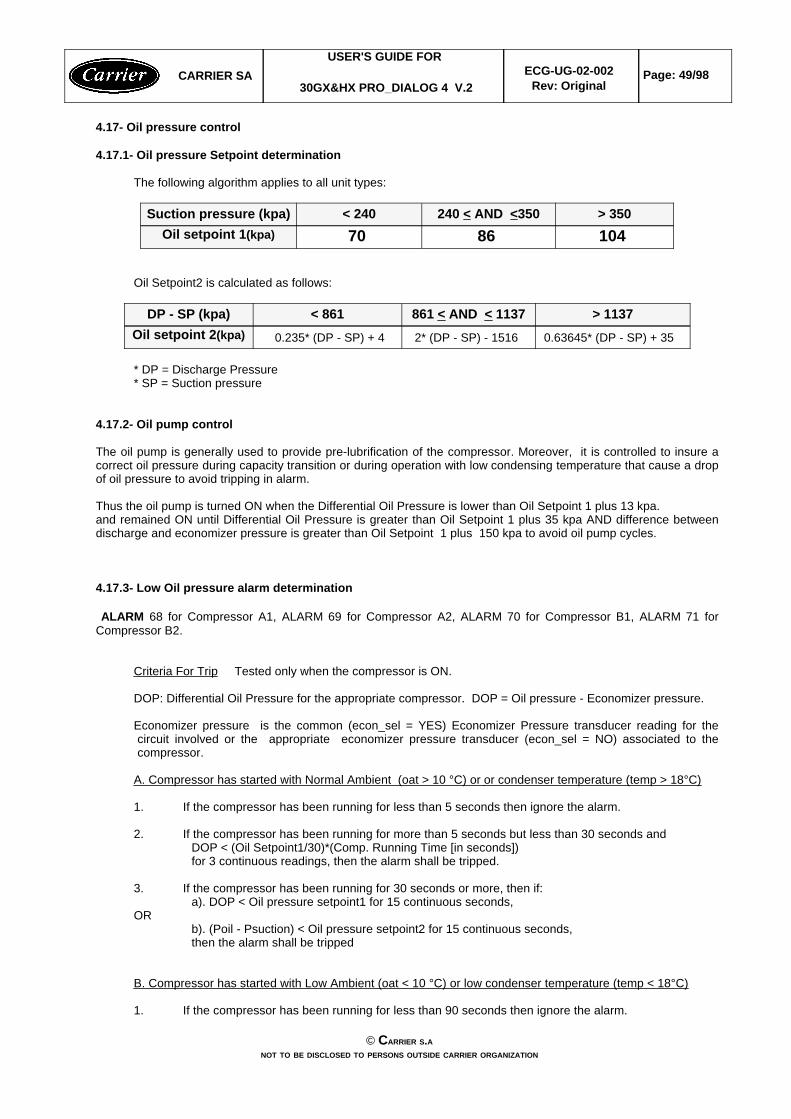
4.17.1- Oil pressure Setpoint determination
The following algorithm applies to all unit types:
104 86 70 Oil setpoint 1(kpa)> 350240 < AND <350< 240Suction pressure (kpa)
Oil Setpoint2 is calculated as follows:
0.63645* (DP - SP) + 35 2* (DP - SP) - 1516 0.235* (DP - SP) + 4Oil setpoint 2(kpa)> 1137861 < AND < 1137< 861DP - SP (kpa)
* DP = Discharge Pressure* SP = Suction pressure
4.17.2- Oil pump control
The oil pump is generally used to provide pre-lubrification of the compressor. Moreover, it is controlled to insure acorrect oil pressure during capacity transition or during operation with low condensing temperature that cause a dropof oil pressure to avoid tripping in alarm.
Thus the oil pump is turned ON when the Differential Oil Pressure is lower than Oil Setpoint 1 plus 13 kpa. and remained ON until Differential Oil Pressure is greater than Oil Setpoint 1 plus 35 kpa AND difference betweendischarge and economizer pressure is greater than Oil Setpoint 1 plus 150 kpa to avoid oil pump cycles.
4.17.3- Low Oil pressure alarm determination
ALARM 68 for Compressor A1, ALARM 69 for Compressor A2, ALARM 70 for Compressor B1, ALARM 71 forCompressor B2.
Criteria For Trip Tested only when the compressor is ON.
DOP: Differential Oil Pressure for the appropriate compressor. DOP = Oil pressure - Economizer pressure.
Economizer pressure is the common (econ_sel = YES) Economizer Pressure transducer reading for thecircuit involved or the appropriate economizer pressure transducer (econ_sel = NO) associated to thecompressor.
A. Compressor has started with Normal Ambient (oat > 10 °C) or or condenser temperature (temp > 18°C)
1. If the compressor has been running for less than 5 seconds then ignore the alarm.
2. If the compressor has been running for more than 5 seconds but less than 30 seconds andDOP < (Oil Setpoint1/30)*(Comp. Running Time [in seconds])for 3 continuous readings, then the alarm shall be tripped.
3. If the compressor has been running for 30 seconds or more, then if:a). DOP < Oil pressure setpoint1 for 15 continuous seconds,
ORb). (Poil - Psuction) < Oil pressure setpoint2 for 15 continuous seconds,then the alarm shall be tripped
B. Compressor has started with Low Ambient (oat < 10 °C) or low condenser temperature (temp < 18°C)
1. If the compressor has been running for less than 90 seconds then ignore the alarm.
CARRIER SAUSER'S GUIDE FOR
30GX&HX PRO_DIALOG 4 V.2ECG-UG-02-002
Rev: OriginalPage: 49/98
© CARRIER S.ANOT TO BE DISCLOSED TO PERSONS OUTSIDE CARRIER ORGANIZATION
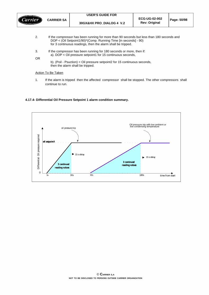
2. If the compressor has been running for more than 90 seconds but less than 180 seconds andDOP < (Oil Setpoint1/90)*(Comp. Running Time [in seconds] - 90)for 3 continuous readings, then the alarm shall be tripped.
3. If the compressor has been running for 180 seconds or more, then if:a). DOP < Oil pressure setpoint1 for 15 continuous seconds,
ORb). (Poil - Psuction) < Oil pressure setpoint2 for 15 continuous seconds,then the alarm shall be tripped.
Action To Be Taken
1. If the alarm is tripped then the affected compressor shall be stopped. The other compressors shallcontinue to run.
4.17.4- Differential Oil Pressure Setpoint 1 alarm condition summary.
CARRIER SAUSER'S GUIDE FOR
30GX&HX PRO_DIALOG 4 V.2ECG-UG-02-002
Rev: OriginalPage: 50/98
© CARRIER S.ANOT TO BE DISCLOSED TO PERSONS OUTSIDE CARRIER ORGANIZATION
0
Dif
fere
ntia
l O
il p
ress
ure
requ
ired
180s
oil pressure trip
Oil pressure trip with low ambient or
90s30s5s
oil setpoint1oil setpoint1oil setpoint1oil setpoint1
3 continued3 continued3 continued3 continuedreading valuesreading valuesreading valuesreading values
3 continued3 continued3 continued3 continuedreading valuesreading valuesreading valuesreading values
15 s delay15 s delay
time from start
low condensing temperature
4.18 - Reclaim Operation
4.18.1 - General Description
This function shall control the air cooled to reclaim or the reclaim to air cooled changeover process.
Reclaim changeover shall be caused either by:w A manual reclaim select change due to a local, remote or CCN command on the unitw A heat reclaim temperature change while reclaim has been selected. This algorithm monitors the entering
reclaim sensor temperature and compares it with the reclaim setpoint to determine if the reclaim can be activeor not.
If the reclaim function has been selected, the reclaim shall become active when the entering reclaim temperaturecomes below the reclaim setpoint minus the reclaim deadband and delay between the last air cooled to reclaimsession is elapsed. It shall become inactive when the entering reclaim temperature comes over the reclaim setpointplus the reclaim deadband.
Non-reclaim to reclaim Changeover shall follow this procedure:
w Turn on the reclaim condenser pumpw Verify the condenser flow is established, if not after 1 minute delay has elapsed, reclaim operation shall be
aborted and an alarm shall be displayed.w Wait for 3 minutes after condenser pump is ON and until the saturated condensing temperature reaches (30
deg C) and superheat is greater than 8.6 ^Cw If saturated condensing temperature is greater than reclaim setpoint + 3.3^F, go to reclaim operation directly (it
is not necessary to make an pumpdown) otherwise, go through pumpdown (see below)w Start the pumpdown sequence : reclaim discharge valve shall be closed and reclaim pumpdown injection valve
shall be open.w Close EXV 6.67 or 3.33% upon the number of compressors on circuit every 10 seconds while pumpdown
pressure is greater than 300 kpa (44 psi), during first minute if EXV is less than 15 % opened. w After a 10 minutes duration or as soon as pumpdown pressure is lower than 300 kpa (44 psi), reclaim injection
valve shall be closed, reclaim operation is effective. Open EXV 13.33% as avoid low saturated suction alarm.w When reclaim operation is active, each circuit fan staging has its own saturated condensing control point
determined as follows:sct_ctrl_x = (hr_ewt + hr_lwt)/ 2 + rsp_x_a * capacity_x + rsp_x_b (x for circuit), rsp_x_a and rsp_x_b areservice parameters in table SERVICE2.
w Pumpdown shall not be necessary if saturated condensing temperature is greater than reclaim setpoint + 6 ^C
Reclaim to non-reclaim Changeover shall follow this procedure:w Turn off the condenser pump. w Close the reclaim pumpdown valve. w Open the reclaim discharge valve if at least a compressor is ON. Otherwise, Close it.
During reclaim operation, if the pumpdown pressure is greater than 400 kpa (59 psi), the pumpdown procedure innon_reclaim to reclaim session shall be initiated. When the number of these abnormal sessions exceeds 2 times,the reclaim operation shall be aborted, the circuit shall return to air cooled mode and an alarm shall be displayed.
At power up or after reset or after the unit capacity goes down to 0%, the function shall return to air cooled mode.
4.18.2 - Reclaim To Air Cooled Changeover Initiation
This shall determine whether the unit shall return to air cooled mode. This can be caused by the following:
Cause #1: Reclaim operation active and reclaim select is no more active
Cause #2: Reclaim mode is active and the entering reclaim temperature is above the range of the reclaimsetpoint + the reclaim dead band divided by 2 : HR_EWT >rsp + hr_deadb/2
Cause #3: Number of consecutive reclaim pumpdown sessions exceeds 2 times
Cause #4: entering reclaim temperature sensor failure
CARRIER SAUSER'S GUIDE FOR
30GX&HX PRO_DIALOG 4 V.2ECG-UG-02-002
Rev: OriginalPage: 51/98
© CARRIER S.ANOT TO BE DISCLOSED TO PERSONS OUTSIDE CARRIER ORGANIZATION
4.18.3 - Air Cooled To Reclaim Changeover Initiation
A non-reclaim to reclaim injection session has been required and at least one compressor is on and the unit is notfailed and the entering reclaim temperature is not failed and this one is below the reclaim setpoint - half of configuredreclaim deadband and delay between the last reclaim injection has elapsed.
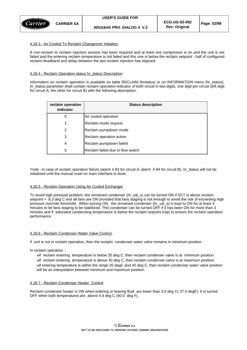
4.18.4 - Reclaim Operation status hr_status Description
Information on reclaim operation is available on table RECLAIM (hrstatus) or on INFORMATION menu (hr_status).hr_status parameter shall contain reclaim operation indicator of both circuit in two digits, one digit per circuit (left digitfor circuit A, the other for circuit B) with the following description :
Reclaim failed due to flow switch 5
Reclaim pumpdown failed 4
Reclaim operation active3
Reclaim pumpdown mode2
Reclaim mode request 1
Air cooled operation0
Status descriptionreclaim operationindicator
*note : in case of reclaim operation failure (alarm # 83 for circuit A, alarm # 84 for circuit B), hr_status will not beinitialized until the manual reset on main interface is done.
4.18.5 - Reclaim Operation Using Air Cooled Exchanger
To avoid high pressure problem, the remained condenser (hr_val_x) can be turned ON if SCT is above reclaimsetpoint + 8.3 deg C and all fans are ON provided that fans staging is not enough to avoid the risk of exceeding highpressure override threshold. When turning ON, the remained condenser (hr_val_a) is kept to ON for at least 3minutes to let fans staging to be stabilized. This condenser can be turned OFF if it has been ON for more than 3minutes and if saturated condensing temperature is below the reclaim setpoint (rsp) to ensure the reclaim operationperformance.
4.18.6 - Reclaim Condenser Water Valve Control
if unit is not in reclaim operation, then the reclaim condenser water valve remains in minimum position.
In reclaim operation : wIf reclaim entering temperature is below 20 deg C, then reclaim condenser valve is at minimum position.wIf reclaim entering temperature is above 40 deg C, then reclaim condenser valve is at maximum position.wIf entering temperature is within the range 20 degC and 40 deg C, then reclaim condenser water valve positionwill be an interpolation between minimum and maximum position.
4.18.7 - Reclaim Condenser Heater Control
Reclaim condenser heater is ON when entering or leaving fluid are lower than 3.0 deg C( 37.4 degF). It is turnedOFF when both temperatures are above 4.4 deg C (40.0 deg F).
CARRIER SAUSER'S GUIDE FOR
30GX&HX PRO_DIALOG 4 V.2ECG-UG-02-002
Rev: OriginalPage: 52/98
© CARRIER S.ANOT TO BE DISCLOSED TO PERSONS OUTSIDE CARRIER ORGANIZATION
4.19 - Two Units Master/Slave Control
4.19.1 - General
This function allows to perform master/slave plant control between two chillers linked by the CCN network. Masterand slave chiller need to operate on the same bus. Master/slave operations shall operate in cooling or heating mode.
To operate properly, the master and the slave chillers must have an additional CHWS sensor located on thecommon chilled leaving piping when the water control is done on the outlet side. This CHWS sensor shall beconnected on each chiller basic board. When the water system control is done on the inlet side no additional CHWSsensor is required.
Parallel chiller control with dedicated pumps is recommended. Chiller must start and stop its own water pumplocated on its own piping. If pumps are not dedicated for each chiller pimping, chiller isolation valves are required:each chiller must open and close its own isolation valve through the control (valve shall be connected to the pumpoutputs).
Water system control with no individual chiller pump control is feasible. It is not recommended when the system loadis low or if the control point is close from the freeze water tripping point (because of system instability that can becaused by the freeze protection override). System flow is constant even if the master or the slave chiller is stopped.In that case, the system pump shall be controlled by the master chiller.
Series chillers with dedicated primary pumping and constant flow shall be feasible but not recommended. Pumpstart/stop must be controlled externally. Each series chiller must control its own isolation and bypass valves: stoppedchiller must be isolated from water flow (chiller pump command shall be used for valves control. Each chiller mustopen and close its own chilled isolation valve).
The master chiller shall monitor all external commands as start/stop, demand limiting or setpoint select. It needs tobe started in Master operating type. The slave chiller must operate in CCN mode. If the master chiller is turned offwhile the master/slave function is active then, the slave chiller shall be stopped.
The master/slave linkage shall not be allowed to operate if any one of the slave chiller CTRL_PNT, DEM_LIM,LAG_LIM, CTRL_PNT HC_SEL or LCW_STPT variables has a force priority higher than a control force. In that case,the master slave operations shall not be allowed or shall be disabled.
The control of the slave chiller shall be done through commands emitted by the master chiller. The slave chiller hasno action in the master/slave operations: it shall only verify that CCN communication with its master is correct.
The master function shall provide the ability to select a lead chiller among the master and the slave. Selection shallbe based on the delta between the master and the slave run hours and shall try to optimize the runtime hours. If thisfunction is unused then, the lead chiller shall always the master. Lead/lag changeover between the master and theslave due to hour balance shall occur during chiller operations odd days at 12:00 a.m. or at startup.
The lead chiller shall always be started first and the lag chiller shall be maintained at zero percent capacity throughmaster forcing the lag demand limit value (LAG_LIM) to 0%. The lag water pump shall be maintained off. When thelead chiller cannot be loaded anymore (because it is loaded at its full available capacity or at the master demandlimit value) then the lag start timer is started. When the lag start timer is elapsed, if the error on the master controlledsetpoint is greater than 3^F and if the pulldown time is elapsed then, the lag chiller water pump shall be turned on (ifrequired by configuration) and the lag chiller shall be allowed to start through master forcing the lag chiller demandlimit value (LAG_LIM) to its own demand limit value. To ensure that the lag chiller will be unloaded first in case ofwater load decrease then, the lead chiller setpoint error shall be reset of upwards 4^F provided that the lag capacityis not zero.
CARRIER SAUSER'S GUIDE FOR
30GX&HX PRO_DIALOG 4 V.2ECG-UG-02-002
Rev: OriginalPage: 53/98
© CARRIER S.ANOT TO BE DISCLOSED TO PERSONS OUTSIDE CARRIER ORGANIZATION
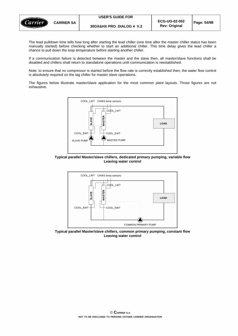
The lead pulldown time tells how long after starting the lead chiller (one time after the master chiller status has beenmanually started) before checking whether to start an additional chiller. This time delay gives the lead chiller achance to pull down the loop temperature before starting another chiller.
If a communication failure is detected between the master and the slave then, all master/slave functions shall bedisabled and chillers shall return to standalone operations until communication is reestablished.
Note: to ensure that no compressor is started before the flow rate is correctly established then, the water flow controlis absolutely required on the lag chiller for master slave operations.
The figures below illustrate master/slave application for the most common plant layouts. Those figures are notexhaustive.
MAS
TER
CHWS temp sensors
COOL_EWTCOOL_EWT
SLAV
E
LOAD
SLAVE PUMP MASTER PUMP
COOL_LWT
COOL_LWT
Typical parallel Master/slave chillers, dedicated primary pumping, variable flowLeaving water control
MAS
TER
CHWS temp sensors
COOL_EWTCOOL_EWT
SLAV
E
LOAD
COMMON PRIMARY PUMP
COOL_LWT
COOL_LWT
Typical parallel Master/slave chillers, common primary pumping, constant flowLeaving water control
CARRIER SAUSER'S GUIDE FOR
30GX&HX PRO_DIALOG 4 V.2ECG-UG-02-002
Rev: OriginalPage: 54/98
© CARRIER S.ANOT TO BE DISCLOSED TO PERSONS OUTSIDE CARRIER ORGANIZATION
MAS
TER
COOL_EWTCOOL_EWT
SLAV
E
LOAD
SLAVE PUMP MASTER PUMP
COOL_LWT
COOL_LWT
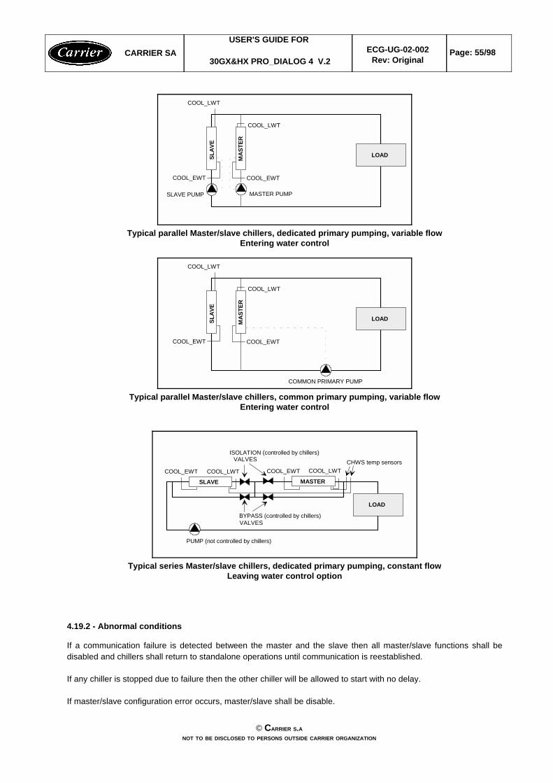
Typical parallel Master/slave chillers, dedicated primary pumping, variable flowEntering water control
MAS
TER
COOL_EWTCOOL_EWT
SLAV
E
LOAD
COMMON PRIMARY PUMP
COOL_LWT
COOL_LWT
Typical parallel Master/slave chillers, common primary pumping, variable flowEntering water control
COOL_EWT
SLAVE
LOAD
CHWS temp sensorsCOOL_EWT COOL_LWTCOOL_LWT
MASTER
PUMP (not controlled by chillers)
ISOLATION (controlled by chillers)VALVES
BYPASS (controlled by chillers)VALVES
Typical series Master/slave chillers, dedicated primary pumping, constant flowLeaving water control option
4.19.2 - Abnormal conditions
If a communication failure is detected between the master and the slave then all master/slave functions shall bedisabled and chillers shall return to standalone operations until communication is reestablished.
If any chiller is stopped due to failure then the other chiller will be allowed to start with no delay.
If master/slave configuration error occurs, master/slave shall be disable.
CARRIER SAUSER'S GUIDE FOR
30GX&HX PRO_DIALOG 4 V.2ECG-UG-02-002
Rev: OriginalPage: 55/98
© CARRIER S.ANOT TO BE DISCLOSED TO PERSONS OUTSIDE CARRIER ORGANIZATION
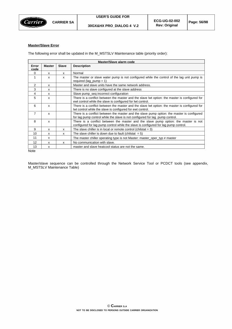
Master/Slave Error
The following error shall be updated in the M_MSTSLV Maintenance table (priority order):
master and slave heatcool status are not the same.x13No communication with slave.xx12The master chiller operating type is not Master: master_oper_typ ≠ masterx11The slave chiller is down due to fault (chilstat = 5)xx10The slave chiller is in local or remote control (chilstat = 3)xx9
There is a conflict between the master and the slave pump option: the master is notconfigured for lag pump control while the slave is configured for lag pump control.
x8
There is a conflict between the master and the slave pump option: the master is configuredfor lag pump control while the slave is not configured for lag pump control.
x7
There is a conflict between the master and the slave lwt option: the master is configured forlwt control while the slave is configured for ewt control.
x6
There is a conflict between the master and the slave lwt option: the master is configured forewt control while the slave is configured for lwt control.
x5Slave pump_seq incorrect configurationx4There is no slave configured at the slave addressx3Master and slave units have the same network address.x2
The master or slave water pump is not configured while the control of the lag unit pump isrequired (lag_pump = 1)
xx1Normalxx0
DescriptionSlaveMasterErrorcode
Master/Slave alarm code
Note
Master/slave sequence can be controlled through the Network Service Tool or PCDCT tools (see appendix, M_MSTSLV Maintenance Table)
CARRIER SAUSER'S GUIDE FOR
30GX&HX PRO_DIALOG 4 V.2ECG-UG-02-002
Rev: OriginalPage: 56/98
© CARRIER S.ANOT TO BE DISCLOSED TO PERSONS OUTSIDE CARRIER ORGANIZATION
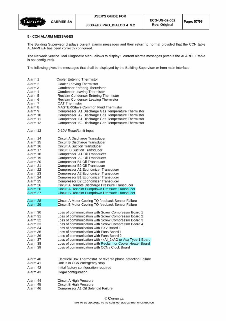
5 - CCN ALARM MESSAGES
The Building Supervisor displays current alarms messages and their return to normal provided that the CCN tableALARMDEF has been correctly configured.
The Network Service Tool Diagnostic Menu allows to display 5 current alarms messages (even if the ALARDEF tableis not configured).
The following gives the messages that shall be displayed by the Building Supervisor or from main interface.
Alarm 1 Cooler Entering ThermistorAlarm 2 Cooler Leaving ThermistorAlarm 3 Condenser Entering ThermistorAlarm 4 Condenser Leaving ThermistorAlarm 5 Reclaim Condenser Entering ThermistorAlarm 6 Reclaim Condenser Leaving ThermistorAlarm 7 OAT ThermistorAlarm 8 MASTER/Slave Common Fluid ThermistorAlarm 9 Compressor A1 Discharge Gas Temperature ThermistorAlarm 10 Compressor A2 Discharge Gas Temperature ThermistorAlarm 11 Compressor B1 Discharge Gas Temperature ThermistorAlarm 12 Compressor B2 Discharge Gas Temperature Thermistor
Alarm 13 0-10V Reset/Limit Input
Alarm 14 Circuit A Discharge TransducerAlarm 15 Circuit B Discharge TransducerAlarm 16 Circuit A Suction TransducerAlarm 17 Circuit B Suction TransducerAlarm 18 Compressor A1 Oil TransducerAlarm 19 Compressor A2 Oil TransducerAlarm 20 Compressor B1 Oil TransducerAlarm 21 Compressor B2 Oil TransducerAlarm 22 Compressor A1 Economizer TransducerAlarm 23 Compressor A2 Economizer TransducerAlarm 24 Compressor B1 Economizer TransducerAlarm 25 Compressor B2 Economizer TransducerAlarm 26 Circuit A Remote Discharge Pressure TransducerAlarm 26 Circuit A Reclaim Pumpdown Pressure TransducerAlarm 27 Circuit B Reclaim Pumpdown Pressure Transducer
Alarm 28 Circuit A Motor Cooling TQ feedback Sensor FailureAlarm 29 Circuit B Motor Cooling TQ feedback Sensor Failure
Alarm 30 Loss of communication with Screw Compressor Board 1Alarm 31 Loss of communication with Screw Compressor Board 2Alarm 32 Loss of communication with Screw Compressor Board 3Alarm 33 Loss of communication with Screw Compressor Board 4Alarm 34 Loss of communication with EXV Board 1Alarm 35 Loss of communication with Fans Board 1Alarm 36 Loss of communication with Fans Board 2Alarm 37 Loss of communication with 4xAI_2xAO or Aux Type 1 Board Alarm 38 Loss of communication with Reclaim or Cooler Heater Board Alarm 39 Loss of communication with CCN / Clock Board
Alarm 40 Electrical Box Thermostat or reverse phase detection FailureAlarm 41 Unit is in CCN emergency stopAlarm 42 Initial factory configuration requiredAlarm 43 Illegal configuration
Alarm 44 Circuit A High PressureAlarm 45 Circuit B High PressureAlarm 46 Compressor A1 Oil Solenoid Failure
CARRIER SAUSER'S GUIDE FOR
30GX&HX PRO_DIALOG 4 V.2ECG-UG-02-002
Rev: OriginalPage: 57/98
© CARRIER S.ANOT TO BE DISCLOSED TO PERSONS OUTSIDE CARRIER ORGANIZATION
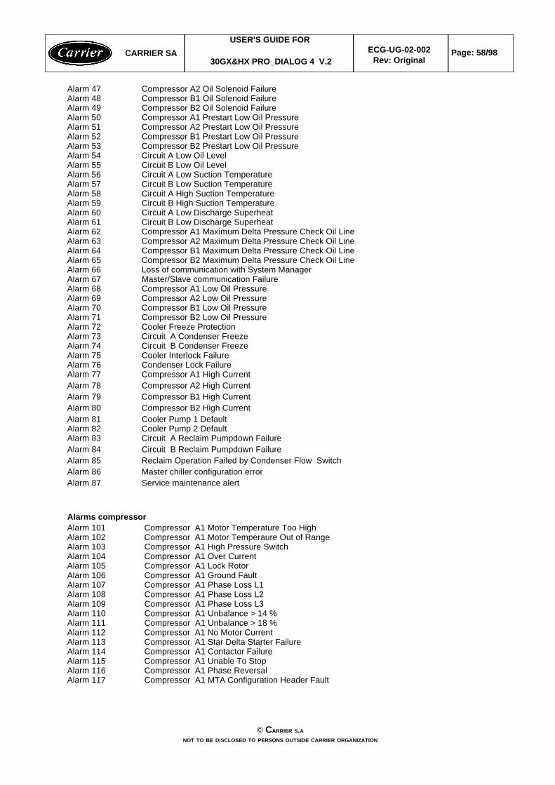
Alarm 47 Compressor A2 Oil Solenoid FailureAlarm 48 Compressor B1 Oil Solenoid FailureAlarm 49 Compressor B2 Oil Solenoid FailureAlarm 50 Compressor A1 Prestart Low Oil PressureAlarm 51 Compressor A2 Prestart Low Oil PressureAlarm 52 Compressor B1 Prestart Low Oil PressureAlarm 53 Compressor B2 Prestart Low Oil PressureAlarm 54 Circuit A Low Oil LevelAlarm 55 Circuit B Low Oil LevelAlarm 56 Circuit A Low Suction TemperatureAlarm 57 Circuit B Low Suction TemperatureAlarm 58 Circuit A High Suction TemperatureAlarm 59 Circuit B High Suction TemperatureAlarm 60 Circuit A Low Discharge Superheat Alarm 61 Circuit B Low Discharge Superheat Alarm 62 Compressor A1 Maximum Delta Pressure Check Oil LineAlarm 63 Compressor A2 Maximum Delta Pressure Check Oil LineAlarm 64 Compressor B1 Maximum Delta Pressure Check Oil LineAlarm 65 Compressor B2 Maximum Delta Pressure Check Oil LineAlarm 66 Loss of communication with System Manager Alarm 67 Master/Slave communication FailureAlarm 68 Compressor A1 Low Oil PressureAlarm 69 Compressor A2 Low Oil PressureAlarm 70 Compressor B1 Low Oil PressureAlarm 71 Compressor B2 Low Oil PressureAlarm 72 Cooler Freeze ProtectionAlarm 73 Circuit A Condenser FreezeAlarm 74 Circuit B Condenser FreezeAlarm 75 Cooler Interlock FailureAlarm 76 Condenser Lock FailureAlarm 77 Compressor A1 High CurrentAlarm 78 Compressor A2 High CurrentAlarm 79 Compressor B1 High CurrentAlarm 80 Compressor B2 High CurrentAlarm 81 Cooler Pump 1 DefaultAlarm 82 Cooler Pump 2 DefaultAlarm 83 Circuit A Reclaim Pumpdown Failure Alarm 84 Circuit B Reclaim Pumpdown FailureAlarm 85 Reclaim Operation Failed by Condenser Flow SwitchAlarm 86 Master chiller configuration errorAlarm 87 Service maintenance alert
Alarms compressorAlarm 101 Compressor A1 Motor Temperature Too HighAlarm 102 Compressor A1 Motor Temperaure Out of RangeAlarm 103 Compressor A1 High Pressure SwitchAlarm 104 Compressor A1 Over Current Alarm 105 Compressor A1 Lock RotorAlarm 106 Compressor A1 Ground FaultAlarm 107 Compressor A1 Phase Loss L1Alarm 108 Compressor A1 Phase Loss L2Alarm 109 Compressor A1 Phase Loss L3Alarm 110 Compressor A1 Unbalance > 14 %Alarm 111 Compressor A1 Unbalance > 18 %Alarm 112 Compressor A1 No Motor CurrentAlarm 113 Compressor A1 Star Delta Starter Failure Alarm 114 Compressor A1 Contactor FailureAlarm 115 Compressor A1 Unable To StopAlarm 116 Compressor A1 Phase ReversalAlarm 117 Compressor A1 MTA Configuration Header Fault
CARRIER SAUSER'S GUIDE FOR
30GX&HX PRO_DIALOG 4 V.2ECG-UG-02-002
Rev: OriginalPage: 58/98
© CARRIER S.ANOT TO BE DISCLOSED TO PERSONS OUTSIDE CARRIER ORGANIZATION
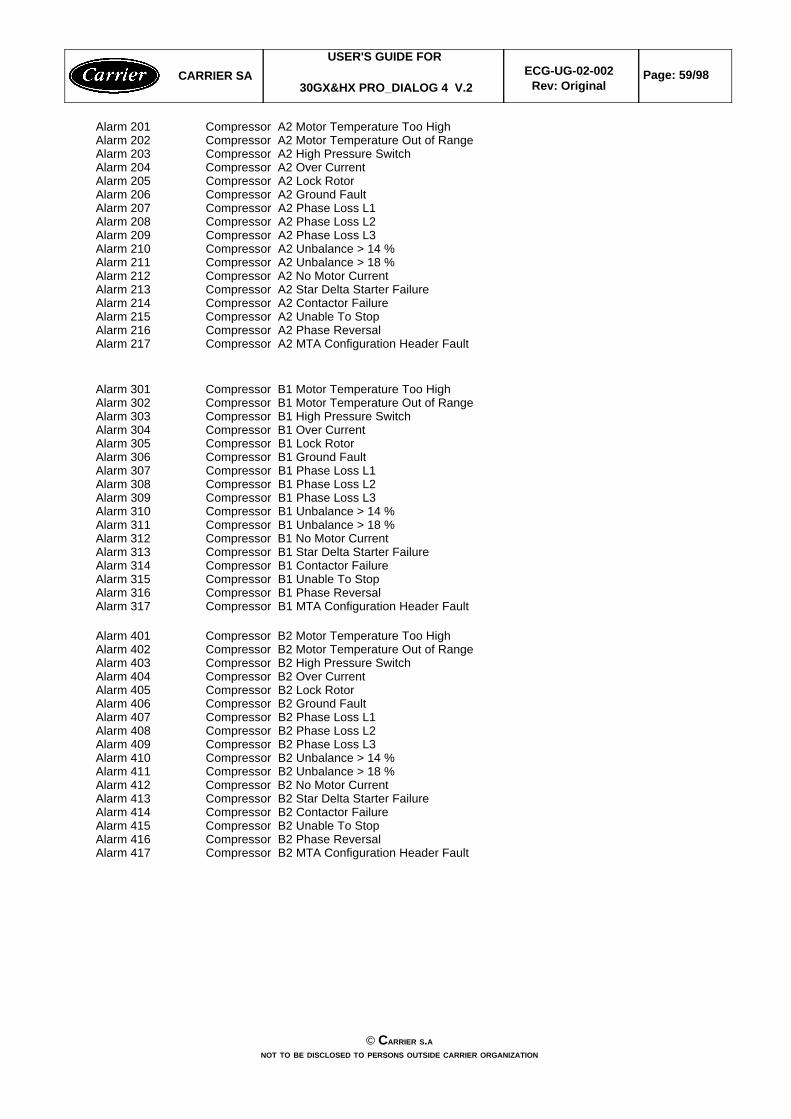
Alarm 201 Compressor A2 Motor Temperature Too HighAlarm 202 Compressor A2 Motor Temperature Out of RangeAlarm 203 Compressor A2 High Pressure SwitchAlarm 204 Compressor A2 Over Current Alarm 205 Compressor A2 Lock RotorAlarm 206 Compressor A2 Ground FaultAlarm 207 Compressor A2 Phase Loss L1Alarm 208 Compressor A2 Phase Loss L2Alarm 209 Compressor A2 Phase Loss L3Alarm 210 Compressor A2 Unbalance > 14 %Alarm 211 Compressor A2 Unbalance > 18 %Alarm 212 Compressor A2 No Motor CurrentAlarm 213 Compressor A2 Star Delta Starter Failure Alarm 214 Compressor A2 Contactor FailureAlarm 215 Compressor A2 Unable To StopAlarm 216 Compressor A2 Phase ReversalAlarm 217 Compressor A2 MTA Configuration Header Fault
Alarm 301 Compressor B1 Motor Temperature Too HighAlarm 302 Compressor B1 Motor Temperature Out of RangeAlarm 303 Compressor B1 High Pressure SwitchAlarm 304 Compressor B1 Over Current Alarm 305 Compressor B1 Lock RotorAlarm 306 Compressor B1 Ground FaultAlarm 307 Compressor B1 Phase Loss L1Alarm 308 Compressor B1 Phase Loss L2Alarm 309 Compressor B1 Phase Loss L3Alarm 310 Compressor B1 Unbalance > 14 %Alarm 311 Compressor B1 Unbalance > 18 %Alarm 312 Compressor B1 No Motor CurrentAlarm 313 Compressor B1 Star Delta Starter Failure Alarm 314 Compressor B1 Contactor FailureAlarm 315 Compressor B1 Unable To StopAlarm 316 Compressor B1 Phase ReversalAlarm 317 Compressor B1 MTA Configuration Header Fault
Alarm 401 Compressor B2 Motor Temperature Too HighAlarm 402 Compressor B2 Motor Temperature Out of RangeAlarm 403 Compressor B2 High Pressure SwitchAlarm 404 Compressor B2 Over Current Alarm 405 Compressor B2 Lock RotorAlarm 406 Compressor B2 Ground FaultAlarm 407 Compressor B2 Phase Loss L1Alarm 408 Compressor B2 Phase Loss L2Alarm 409 Compressor B2 Phase Loss L3Alarm 410 Compressor B2 Unbalance > 14 %Alarm 411 Compressor B2 Unbalance > 18 %Alarm 412 Compressor B2 No Motor CurrentAlarm 413 Compressor B2 Star Delta Starter Failure Alarm 414 Compressor B2 Contactor FailureAlarm 415 Compressor B2 Unable To StopAlarm 416 Compressor B2 Phase ReversalAlarm 417 Compressor B2 MTA Configuration Header Fault
CARRIER SAUSER'S GUIDE FOR
30GX&HX PRO_DIALOG 4 V.2ECG-UG-02-002
Rev: OriginalPage: 59/98
© CARRIER S.ANOT TO BE DISCLOSED TO PERSONS OUTSIDE CARRIER ORGANIZATION
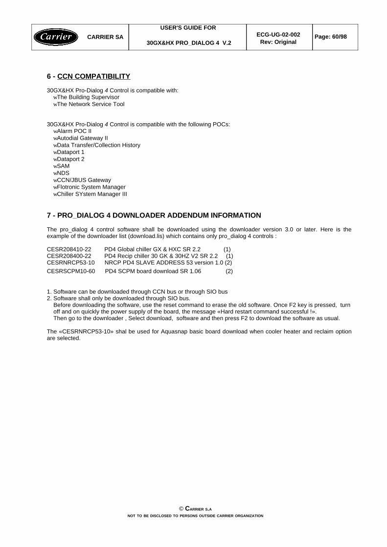
6 - CCN COMPATIBILITY
30GX&HX Pro-Dialog 4 Control is compatible with:wThe Building SupervisorwThe Network Service Tool
30GX&HX Pro-Dialog 4 Control is compatible with the following POCs:wAlarm POC IIwAutodial Gateway IIwData Transfer/Collection HistorywDataport 1wDataport 2wSAMwNDSwCCN/JBUS GatewaywFlotronic System ManagerwChiller SYstem Manager III
7 - PRO_DIALOG 4 DOWNLOADER ADDENDUM INFORMATION
The pro_dialog 4 control software shall be downloaded using the downloader version 3.0 or later. Here is theexample of the downloader list (download.lis) which contains only pro_dialog 4 controls :
CESR208410-22 PD4 Global chiller GX & HXC SR 2.2 (1)CESR208400-22 PD4 Recip chiller 30 GK & 30HZ V2 SR 2.2 (1)CESRNRCP53-10 NRCP PD4 SLAVE ADDRESS 53 version 1.0 (2)CESRSCPM10-60 PD4 SCPM board download SR 1.06 (2)
1. Software can be downloaded through CCN bus or through SIO bus2. Software shall only be downloaded through SIO bus. Before downloading the software, use the reset command to erase the old software. Once F2 key is pressed, turn off and on quickly the power supply of the board, the message «Hard restart command successful !». Then go to the downloader , Select download, software and then press F2 to download the software as usual.
The «CESRNRCP53-10» shal be used for Aquasnap basic board download when cooler heater and reclaim optionare selected.
CARRIER SAUSER'S GUIDE FOR
30GX&HX PRO_DIALOG 4 V.2ECG-UG-02-002
Rev: OriginalPage: 60/98
© CARRIER S.ANOT TO BE DISCLOSED TO PERSONS OUTSIDE CARRIER ORGANIZATION
APPENDIX A - CCN DISPLAY, SETPOINT, MAINTENANCE TABLE SCREENS ...
DISPLAY SCREEN
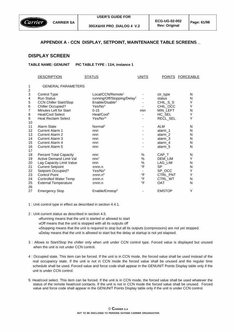
TABLE NAME: GENUNIT PIC TABLE TYPE : 11H, instance 1
DESCRIPTION STATUS UNITS POINTS FORCEABLE
1 GENERAL PARAMETERS23 Control Type Local/CCN/Remote1 - ctr_type N4 Run Status running/Off/Stopping/Delay2 - status N5 CCN Chiller Start/Stop Enable/Dsable3 - CHIL_S_S Y6 Chiller Occupied? Yes/No4 - CHIL_OCC Y7 Minutes Left for Start 0-15 min MIN_LEFT N8 Heat/Cool Select Heat/Cool5 - HC_SEL Y9 Heat Reclaim Select Yes/No10 - RECL_SEL Y1011 Alarm State Normal6 - ALM N12 Current Alarm 1 nnn - alarm_1 N13 Current Alarm 2 nnn - alarm_2 N14 Current Alarm 3 nnn - alarm_3 N15 Current Alarm 4 nnn - alarm_4 N16 Current Alarm 5 nnn - alarm_5 N1718 Percent Total Capacity nnn % CAP_T N19 Active Demand Limit Val nnn7 % DEM_LIM Y20 Lag Capacity Limit Value nnn % LAG_LIM N21 Current Setpoint ±nnn.n °F SP N22 Setpoint Occupied? Yes/No4 - SP_OCC Y23 Control Point ±nnn.n8 °F CTRL_PNT Y24 Controlled Water Temp ±nnn.n °F CTRL_WT N25 External Temperature ±nnn.n °F OAT N2627 Emergency Stop Enable/Emstop9 - EMSTOP Y
1 : Unit control type in effect as described in section 4.4.1.
2 : Unit current status as described in section 4.5.wRunning means that the unit is started or allowed to startwOff means that the unit is stopped with all its outputs offwStopping means that the unit is required to stop but all its outputs (compressors) are not yet stopped.wDelay means that the unit is allowed to start but the delay at startup is not yet elapsed.
3 : Allows to Start/Stop the chiller only when unit under CCN control type. Forced value is displayed but unusedwhen the unit is not under CCN control.
4 : Occupied state. This item can be forced. If the unit is in CCN mode, the forced value shall be used instead of thereal occupancy state. If the unit is not in CCN mode the forced value shall be unused and the regular timeschedule shall be used. Forced value and force code shall appear in the GENUNIT Points Display table only if theunit is under CCN control.
5: Heat/cool select. This item can be forced. If the unit is in CCN mode, the forced value shall be used whatever thestatus of the remote heat/cool contacts. If the unit is not in CCN mode the forced value shall be unused. Forcedvalue and force code shall appear in the GENUNIT Points Display table only if the unit is under CCN control.
CARRIER SAUSER'S GUIDE FOR
30GX&HX PRO_DIALOG 4 V.2ECG-UG-02-002
Rev: OriginalPage: 61/98
© CARRIER S.ANOT TO BE DISCLOSED TO PERSONS OUTSIDE CARRIER ORGANIZATION
6 : Alarm statuswNormal (no alarm)wPartial (alarm but unit is not down)wShutdown (unit is down)
7: Active Demand Limit Value. This item can be forced. If the unit is in CCN mode, the forced value shall be usedwhatever the status of the external limit switch contact and whatever the value of the demand limit switch setpoint.If the unit is not in CCN mode the forced value shall be unused. Forced value and force code shall appear in theGENUNIT Points Display table only if the unit is under CCN control.
8: Control Point. This item can be forced. If the unit is in CCN mode, the forced value shall be used instead of thereal control point calculation. If the unit is not in CCN mode the forced value shall be unused. Forced value andforce code shall appear in the GENUNIT Points Display table only if the unit is under CCN control.
9 : Active all the time even if the unit is not in CCN control type.
10: Heat Reclaim Select. This item can be forced. If the unit is in CCN mode, the forced value shall be usedwhatever the status of the remote reclaim switch. Forced value and force code shall appear in the GENUNITPoints Display table only if the unit is under CCN control.
DISPLAY SCREEN
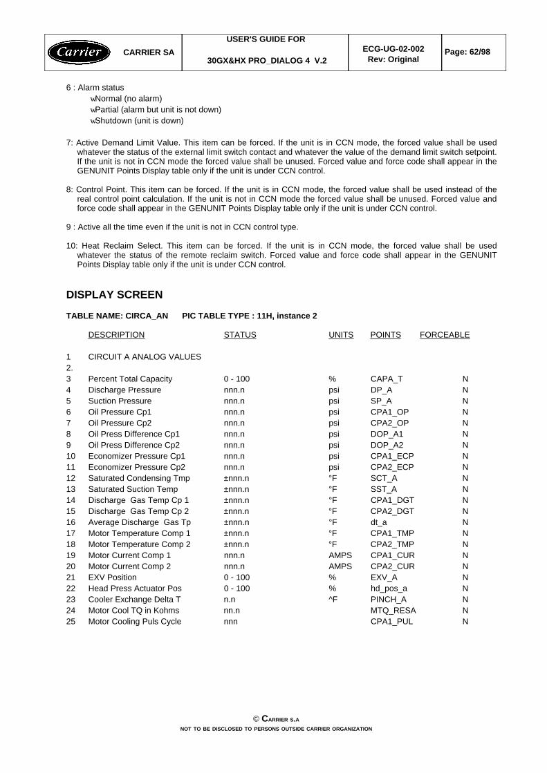
TABLE NAME: CIRCA_AN PIC TABLE TYPE : 11H, instance 2
DESCRIPTION STATUS UNITS POINTS FORCEABLE
1 CIRCUIT A ANALOG VALUES2.3 Percent Total Capacity 0 - 100 % CAPA_T N4 Discharge Pressure nnn.n psi DP_A N5 Suction Pressure nnn.n psi SP_A N6 Oil Pressure Cp1 nnn.n psi CPA1_OP N7 Oil Pressure Cp2 nnn.n psi CPA2_OP N8 Oil Press Difference Cp1 nnn.n psi DOP_A1 N9 Oil Press Difference Cp2 nnn.n psi DOP_A2 N10 Economizer Pressure Cp1 nnn.n psi CPA1_ECP N11 Economizer Pressure Cp2 nnn.n psi CPA2_ECP N12 Saturated Condensing Tmp ±nnn.n °F SCT_A N13 Saturated Suction Temp ±nnn.n °F SST_A N14 Discharge Gas Temp Cp 1 ±nnn.n °F CPA1_DGT N15 Discharge Gas Temp Cp 2 ±nnn.n °F CPA2_DGT N16 Average Discharge Gas Tp ±nnn.n °F dt_a N17 Motor Temperature Comp 1 ±nnn.n °F CPA1_TMP N18 Motor Temperature Comp 2 ±nnn.n °F CPA2_TMP N19 Motor Current Comp 1 nnn.n AMPS CPA1_CUR N20 Motor Current Comp 2 nnn.n AMPS CPA2_CUR N21 EXV Position 0 - 100 % EXV_A N22 Head Press Actuator Pos 0 - 100 % hd_pos_a N23 Cooler Exchange Delta T n.n ^F PINCH_A N24 Motor Cool TQ in Kohms nn.n MTQ_RESA N25 Motor Cooling Puls Cycle nnn CPA1_PUL N
CARRIER SAUSER'S GUIDE FOR
30GX&HX PRO_DIALOG 4 V.2ECG-UG-02-002
Rev: OriginalPage: 62/98
© CARRIER S.ANOT TO BE DISCLOSED TO PERSONS OUTSIDE CARRIER ORGANIZATION
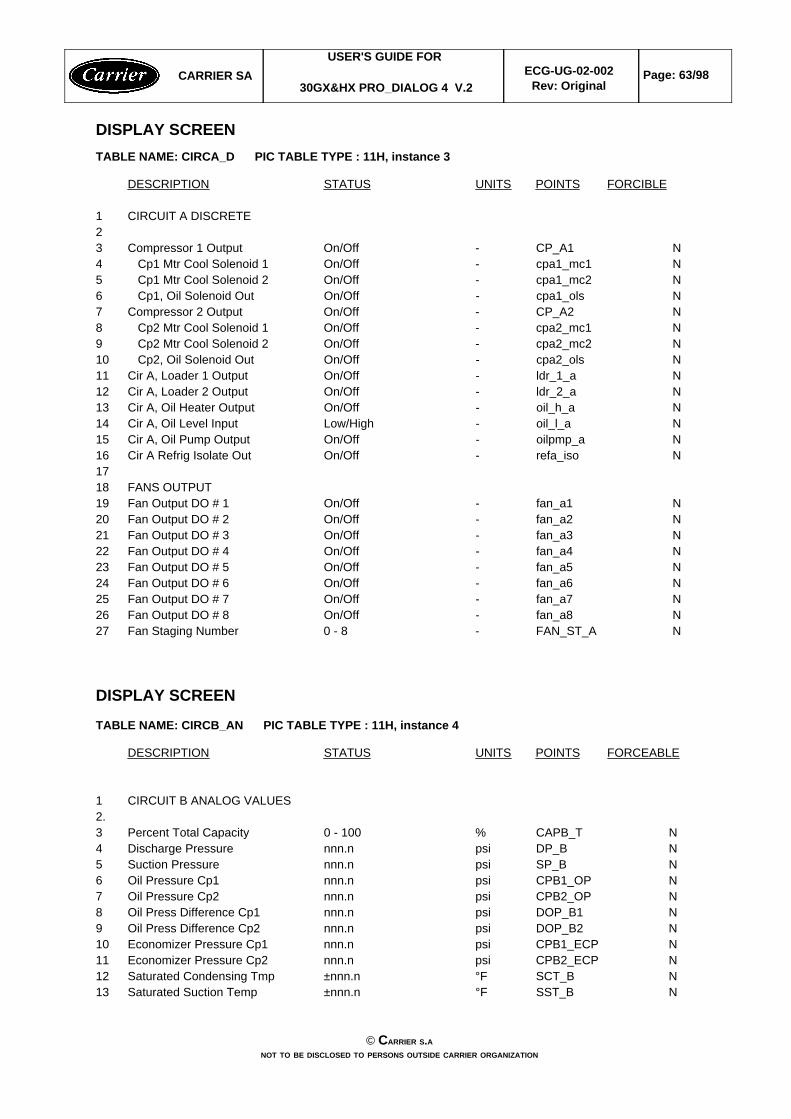
DISPLAY SCREENTABLE NAME: CIRCA_D PIC TABLE TYPE : 11H, instance 3
DESCRIPTION STATUS UNITS POINTS FORCIBLE
1 CIRCUIT A DISCRETE23 Compressor 1 Output On/Off - CP_A1 N4 Cp1 Mtr Cool Solenoid 1 On/Off - cpa1_mc1 N5 Cp1 Mtr Cool Solenoid 2 On/Off - cpa1_mc2 N6 Cp1, Oil Solenoid Out On/Off - cpa1_ols N7 Compressor 2 Output On/Off - CP_A2 N8 Cp2 Mtr Cool Solenoid 1 On/Off - cpa2_mc1 N9 Cp2 Mtr Cool Solenoid 2 On/Off - cpa2_mc2 N10 Cp2, Oil Solenoid Out On/Off - cpa2_ols N11 Cir A, Loader 1 Output On/Off - ldr_1_a N12 Cir A, Loader 2 Output On/Off - ldr_2_a N13 Cir A, Oil Heater Output On/Off - oil_h_a N14 Cir A, Oil Level Input Low/High - oil_l_a N15 Cir A, Oil Pump Output On/Off - oilpmp_a N16 Cir A Refrig Isolate Out On/Off - refa_iso N1718 FANS OUTPUT19 Fan Output DO # 1 On/Off - fan_a1 N20 Fan Output DO # 2 On/Off - fan_a2 N21 Fan Output DO # 3 On/Off - fan_a3 N22 Fan Output DO # 4 On/Off - fan_a4 N23 Fan Output DO # 5 On/Off - fan_a5 N24 Fan Output DO # 6 On/Off - fan_a6 N25 Fan Output DO # 7 On/Off - fan_a7 N26 Fan Output DO # 8 On/Off - fan_a8 N27 Fan Staging Number 0 - 8 - FAN_ST_A N
DISPLAY SCREEN
TABLE NAME: CIRCB_AN PIC TABLE TYPE : 11H, instance 4
DESCRIPTION STATUS UNITS POINTS FORCEABLE
1 CIRCUIT B ANALOG VALUES2.3 Percent Total Capacity 0 - 100 % CAPB_T N4 Discharge Pressure nnn.n psi DP_B N5 Suction Pressure nnn.n psi SP_B N6 Oil Pressure Cp1 nnn.n psi CPB1_OP N7 Oil Pressure Cp2 nnn.n psi CPB2_OP N8 Oil Press Difference Cp1 nnn.n psi DOP_B1 N9 Oil Press Difference Cp2 nnn.n psi DOP_B2 N10 Economizer Pressure Cp1 nnn.n psi CPB1_ECP N11 Economizer Pressure Cp2 nnn.n psi CPB2_ECP N12 Saturated Condensing Tmp ±nnn.n °F SCT_B N13 Saturated Suction Temp ±nnn.n °F SST_B N
CARRIER SAUSER'S GUIDE FOR
30GX&HX PRO_DIALOG 4 V.2ECG-UG-02-002
Rev: OriginalPage: 63/98
© CARRIER S.ANOT TO BE DISCLOSED TO PERSONS OUTSIDE CARRIER ORGANIZATION
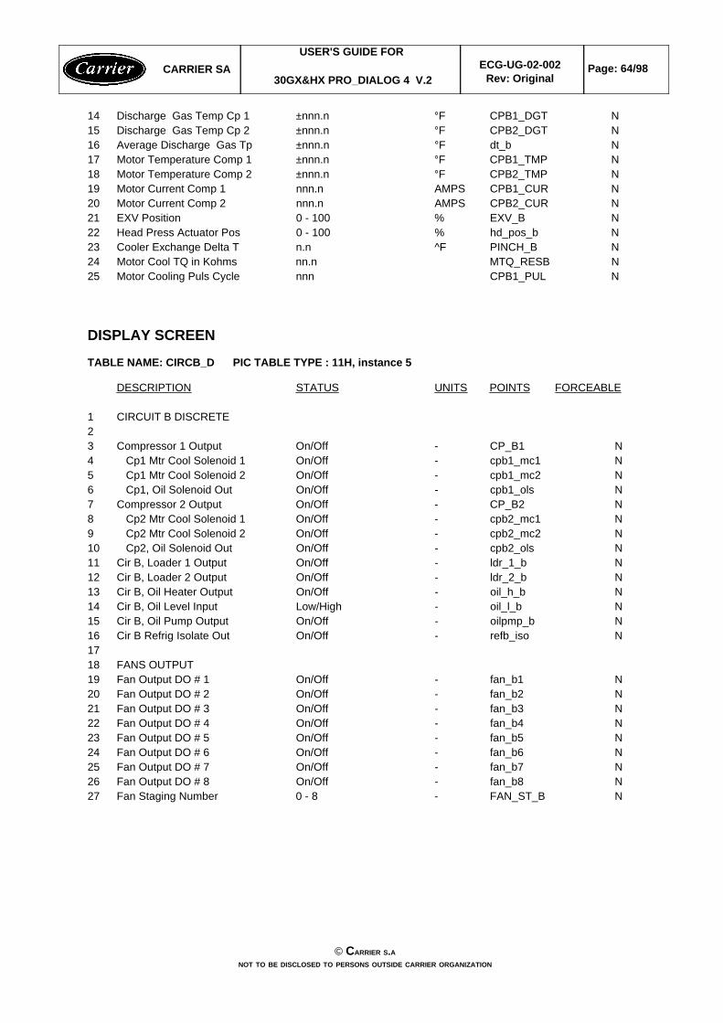
14 Discharge Gas Temp Cp 1 ±nnn.n °F CPB1_DGT N15 Discharge Gas Temp Cp 2 ±nnn.n °F CPB2_DGT N16 Average Discharge Gas Tp ±nnn.n °F dt_b N17 Motor Temperature Comp 1 ±nnn.n °F CPB1_TMP N18 Motor Temperature Comp 2 ±nnn.n °F CPB2_TMP N19 Motor Current Comp 1 nnn.n AMPS CPB1_CUR N20 Motor Current Comp 2 nnn.n AMPS CPB2_CUR N21 EXV Position 0 - 100 % EXV_B N22 Head Press Actuator Pos 0 - 100 % hd_pos_b N23 Cooler Exchange Delta T n.n ^F PINCH_B N24 Motor Cool TQ in Kohms nn.n MTQ_RESB N25 Motor Cooling Puls Cycle nnn CPB1_PUL N
DISPLAY SCREEN
TABLE NAME: CIRCB_D PIC TABLE TYPE : 11H, instance 5
DESCRIPTION STATUS UNITS POINTS FORCEABLE
1 CIRCUIT B DISCRETE23 Compressor 1 Output On/Off - CP_B1 N4 Cp1 Mtr Cool Solenoid 1 On/Off - cpb1_mc1 N5 Cp1 Mtr Cool Solenoid 2 On/Off - cpb1_mc2 N6 Cp1, Oil Solenoid Out On/Off - cpb1_ols N7 Compressor 2 Output On/Off - CP_B2 N8 Cp2 Mtr Cool Solenoid 1 On/Off - cpb2_mc1 N9 Cp2 Mtr Cool Solenoid 2 On/Off - cpb2_mc2 N10 Cp2, Oil Solenoid Out On/Off - cpb2_ols N11 Cir B, Loader 1 Output On/Off - ldr_1_b N12 Cir B, Loader 2 Output On/Off - ldr_2_b N13 Cir B, Oil Heater Output On/Off - oil_h_b N14 Cir B, Oil Level Input Low/High - oil_l_b N15 Cir B, Oil Pump Output On/Off - oilpmp_b N16 Cir B Refrig Isolate Out On/Off - refb_iso N1718 FANS OUTPUT19 Fan Output DO # 1 On/Off - fan_b1 N20 Fan Output DO # 2 On/Off - fan_b2 N21 Fan Output DO # 3 On/Off - fan_b3 N22 Fan Output DO # 4 On/Off - fan_b4 N23 Fan Output DO # 5 On/Off - fan_b5 N24 Fan Output DO # 6 On/Off - fan_b6 N25 Fan Output DO # 7 On/Off - fan_b7 N26 Fan Output DO # 8 On/Off - fan_b8 N27 Fan Staging Number 0 - 8 - FAN_ST_B N
CARRIER SAUSER'S GUIDE FOR
30GX&HX PRO_DIALOG 4 V.2ECG-UG-02-002
Rev: OriginalPage: 64/98
© CARRIER S.ANOT TO BE DISCLOSED TO PERSONS OUTSIDE CARRIER ORGANIZATION
DISPLAY SCREEN
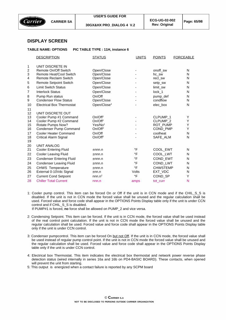
TABLE NAME: OPTIONS PIC TABLE TYPE : 11H, instance 6
DESCRIPTION STATUS UNITS POINTS FORCEABLE
1 UNIT DISCRETE IN2 Remote On/Off Switch Open/Close - onoff_sw N3 Remote Heat/Cool Switch Open/Close - hc_sw N4 Remote Reclaim Switch Open/Close - recl_sw N5 Remote Setpoint Switch Open/Close - setp_sw N6 Limit Switch Status Open/Close - limit_sw N7 Interlock Status Open/Close - lock_1 N8 Pump Run status On/Off - pump_def N9 Condenser Flow Status Open/Close - condflow N10 Electrical Box Thermostat Open/Close4 - elec_box N1112 UNIT DISCRETE OUT13 Cooler Pump #1 Command On/Off1 - CLPUMP_1 Y14 Cooler Pump #2 Command On/Off1 - CLPUMP_2 Y15 Rotate Pumps Now? Yes/No1 - ROT_PUMP Y16 Condenser Pump Command On/Off3 - COND_PMP Y17 Cooler Heater Command On/Off - coolheat N18 Critical Alarm Signal On/Off5 - SAFE_ALM N1920 UNIT ANALOG21 Cooler Entering Fluid ±nnn.n °F COOL_EWT N22 Cooler Leaving Fluid ±nnn.n °F COOL_LWT N23 Condenser Entering Fluid ±nnn.n °F COND_EWT N24 Condenser Leaving Fluid ±nnn.n °F COND_LWT N25 CHWS Temperature ±nnn.n °F CHWSTEMP N26 External 0-10Vdc Signal ±nn.n Volts EXT_VDC N27 Current Cond Setpoint nnn.n2 °F COND_SP Y28 Chiller Total Current nnn.n amps tot_curr N
1: Cooler pump control. This item can be forced On or Off if the unit is in CCN mode and if the CHIL_S_S isdisabled. If the unit is not in CCN mode the forced value shall be unused and the regular calculation shall beused. Forced value and force code shall appear in the OPTIONS Points Display table only if the unit is under CCNcontrol and if CHIL_S_S is disabled. If PUMP#1 is forced, no force shall be allowed on PUMP_2 and vice versa.
2: Condensing Setpoint. This item can be forced. If the unit is in CCN mode, the forced value shall be used insteadof the real control point calculation. If the unit is not in CCN mode the forced value shall be unused and theregular calculation shall be used. Forced value and force code shall appear in the OPTIONS Points Display tableonly if the unit is under CCN control.
3: Condenser pumpcontrol. This item can be forced On but not Off. If the unit is in CCN mode, the forced value shallbe used instead of regular pump control point. If the unit is not in CCN mode the forced value shall be unused andthe regular calculation shall be used. Forced value and force code shall appear in the OPTIONS Points Displaytable only if the unit is under CCN control.
4: Electrical box Thermostat. This item indicates the electrical box thermostat and network power reverse phasedetection status (wired internally in series 16a and 16b on PD4-BASIC BOARD). These contacts, when openedwill prevent the unit from starting.
5: This output is energized when a contact failure is reported by any SCPM board
CARRIER SAUSER'S GUIDE FOR
30GX&HX PRO_DIALOG 4 V.2ECG-UG-02-002
Rev: OriginalPage: 65/98
© CARRIER S.ANOT TO BE DISCLOSED TO PERSONS OUTSIDE CARRIER ORGANIZATION
DISPLAY SCREEN
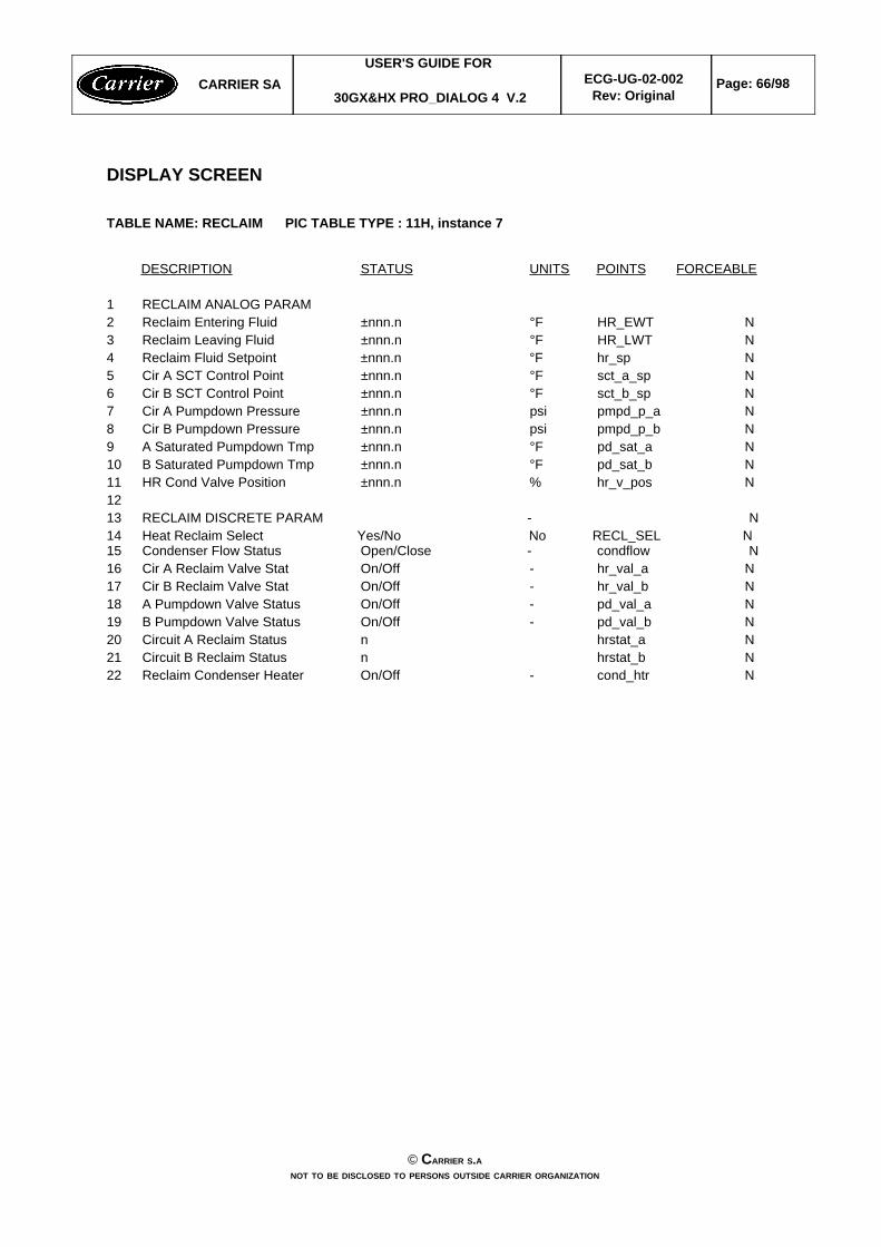
TABLE NAME: RECLAIM PIC TABLE TYPE : 11H, instance 7
DESCRIPTION STATUS UNITS POINTS FORCEABLE
1 RECLAIM ANALOG PARAM2 Reclaim Entering Fluid ±nnn.n °F HR_EWT N3 Reclaim Leaving Fluid ±nnn.n °F HR_LWT N4 Reclaim Fluid Setpoint ±nnn.n °F hr_sp N5 Cir A SCT Control Point ±nnn.n °F sct_a_sp N6 Cir B SCT Control Point ±nnn.n °F sct_b_sp N7 Cir A Pumpdown Pressure ±nnn.n psi pmpd_p_a N8 Cir B Pumpdown Pressure ±nnn.n psi pmpd_p_b N9 A Saturated Pumpdown Tmp ±nnn.n °F pd_sat_a N10 B Saturated Pumpdown Tmp ±nnn.n °F pd_sat_b N11 HR Cond Valve Position ±nnn.n % hr_v_pos N1213 RECLAIM DISCRETE PARAM - N14 Heat Reclaim Select Yes/No No RECL_SEL N15 Condenser Flow Status Open/Close - condflow N16 Cir A Reclaim Valve Stat On/Off - hr_val_a N17 Cir B Reclaim Valve Stat On/Off - hr_val_b N18 A Pumpdown Valve Status On/Off - pd_val_a N19 B Pumpdown Valve Status On/Off - pd_val_b N20 Circuit A Reclaim Status n hrstat_a N21 Circuit B Reclaim Status n hrstat_b N22 Reclaim Condenser Heater On/Off - cond_htr N
CARRIER SAUSER'S GUIDE FOR
30GX&HX PRO_DIALOG 4 V.2ECG-UG-02-002
Rev: OriginalPage: 66/98
© CARRIER S.ANOT TO BE DISCLOSED TO PERSONS OUTSIDE CARRIER ORGANIZATION
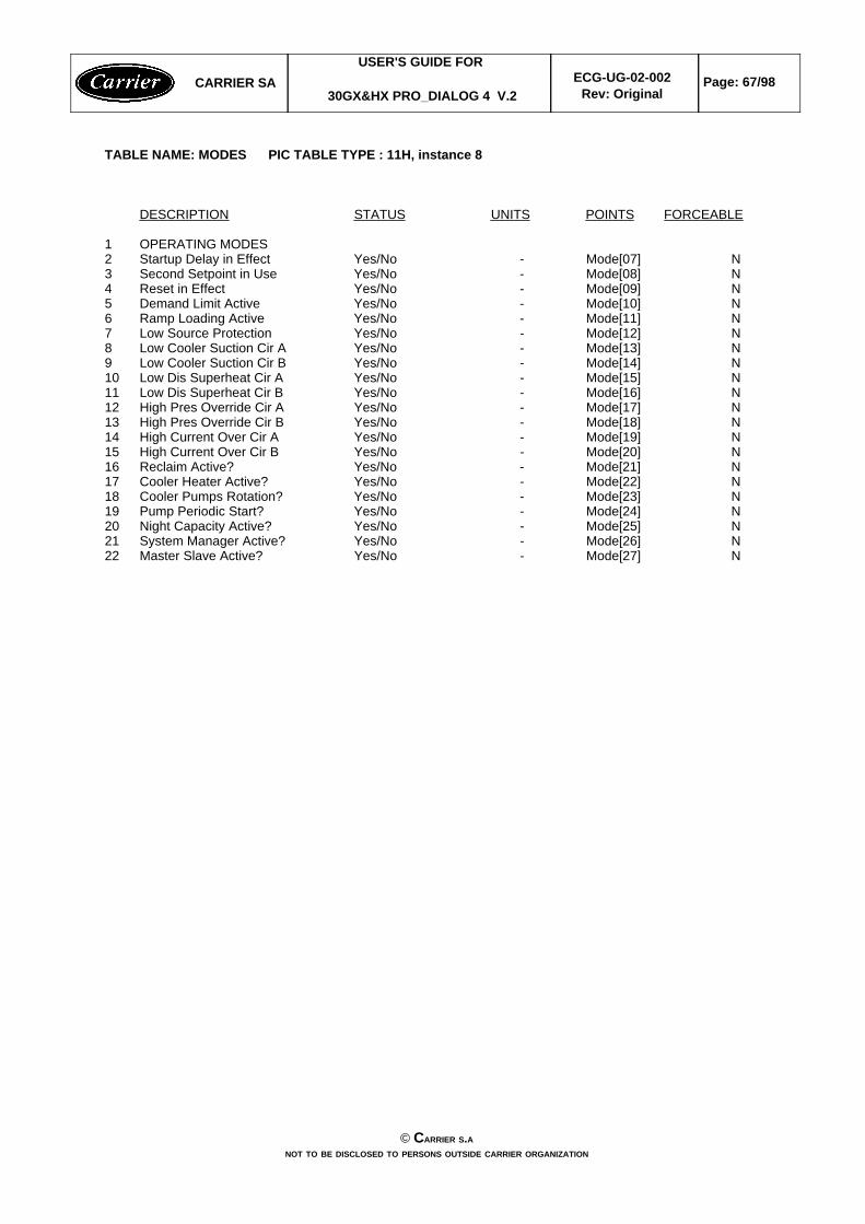
TABLE NAME: MODES PIC TABLE TYPE : 11H, instance 8
DESCRIPTION STATUS UNITS POINTS FORCEABLE
1 OPERATING MODES2 Startup Delay in Effect Yes/No - Mode[07] N3 Second Setpoint in Use Yes/No - Mode[08] N4 Reset in Effect Yes/No - Mode[09] N5 Demand Limit Active Yes/No - Mode[10] N6 Ramp Loading Active Yes/No - Mode[11] N7 Low Source Protection Yes/No - Mode[12] N8 Low Cooler Suction Cir A Yes/No - Mode[13] N9 Low Cooler Suction Cir B Yes/No - Mode[14] N10 Low Dis Superheat Cir A Yes/No - Mode[15] N11 Low Dis Superheat Cir B Yes/No - Mode[16] N12 High Pres Override Cir A Yes/No - Mode[17] N13 High Pres Override Cir B Yes/No - Mode[18] N14 High Current Over Cir A Yes/No - Mode[19] N15 High Current Over Cir B Yes/No - Mode[20] N16 Reclaim Active? Yes/No - Mode[21] N17 Cooler Heater Active? Yes/No - Mode[22] N18 Cooler Pumps Rotation? Yes/No - Mode[23] N19 Pump Periodic Start? Yes/No - Mode[24] N20 Night Capacity Active? Yes/No - Mode[25] N21 System Manager Active? Yes/No - Mode[26] N22 Master Slave Active? Yes/No - Mode[27] N
CARRIER SAUSER'S GUIDE FOR
30GX&HX PRO_DIALOG 4 V.2ECG-UG-02-002
Rev: OriginalPage: 67/98
© CARRIER S.ANOT TO BE DISCLOSED TO PERSONS OUTSIDE CARRIER ORGANIZATION
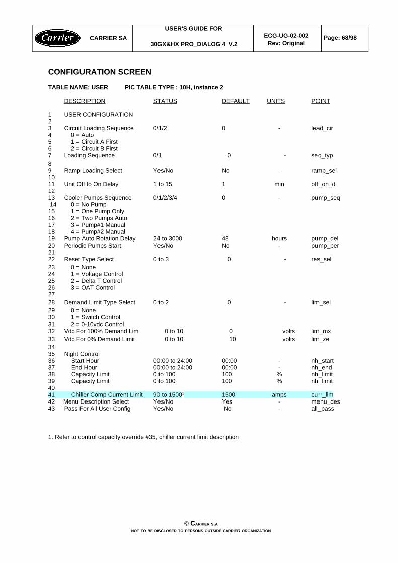
CONFIGURATION SCREEN
TABLE NAME: USER PIC TABLE TYPE : 10H, instance 2
DESCRIPTION STATUS DEFAULT UNITS POINT
1 USER CONFIGURATION23 Circuit Loading Sequence 0/1/2 0 - lead_cir4 0 = Auto5 1 = Circuit A First6 2 = Circuit B First7 Loading Sequence 0/1 0 - seq_typ89 Ramp Loading Select Yes/No No - ramp_sel1011 Unit Off to On Delay 1 to 15 1 min off_on_d1213 Cooler Pumps Sequence 0/1/2/3/4 0 - pump_seq 14 0 = No Pump15 1 = One Pump Only16 2 = Two Pumps Auto17 3 = Pump#1 Manual18 4 = Pump#2 Manual19 Pump Auto Rotation Delay 24 to 3000 48 hours pump_del20 Periodic Pumps Start Yes/No No - pump_per2122 Reset Type Select 0 to 3 0 - res_sel23 0 = None24 1 = Voltage Control 25 2 = Delta T Control26 3 = OAT Control2728 Demand Limit Type Select 0 to 2 0 - lim_sel29 0 = None30 1 = Switch Control31 2 = 0-10vdc Control32 Vdc For 100% Demand Lim 0 to 10 0 volts lim_mx33 Vdc For 0% Demand Limit 0 to 10 10 volts lim_ze3435 Night Control36 Start Hour 00:00 to 24:00 00:00 - nh_start37 End Hour 00:00 to 24:00 00:00 - nh_end38 Capacity Limit 0 to 100 100 % nh_limit39 Capacity Limit 0 to 100 100 % nh_limit4041 Chiller Comp Current Limit 90 to 15001 1500 amps curr_lim42 Menu Description Select Yes/No Yes - menu_des43 Pass For All User Config Yes/No No - all_pass
1. Refer to control capacity override #35, chiller current limit description
CARRIER SAUSER'S GUIDE FOR
30GX&HX PRO_DIALOG 4 V.2ECG-UG-02-002
Rev: OriginalPage: 68/98
© CARRIER S.ANOT TO BE DISCLOSED TO PERSONS OUTSIDE CARRIER ORGANIZATION
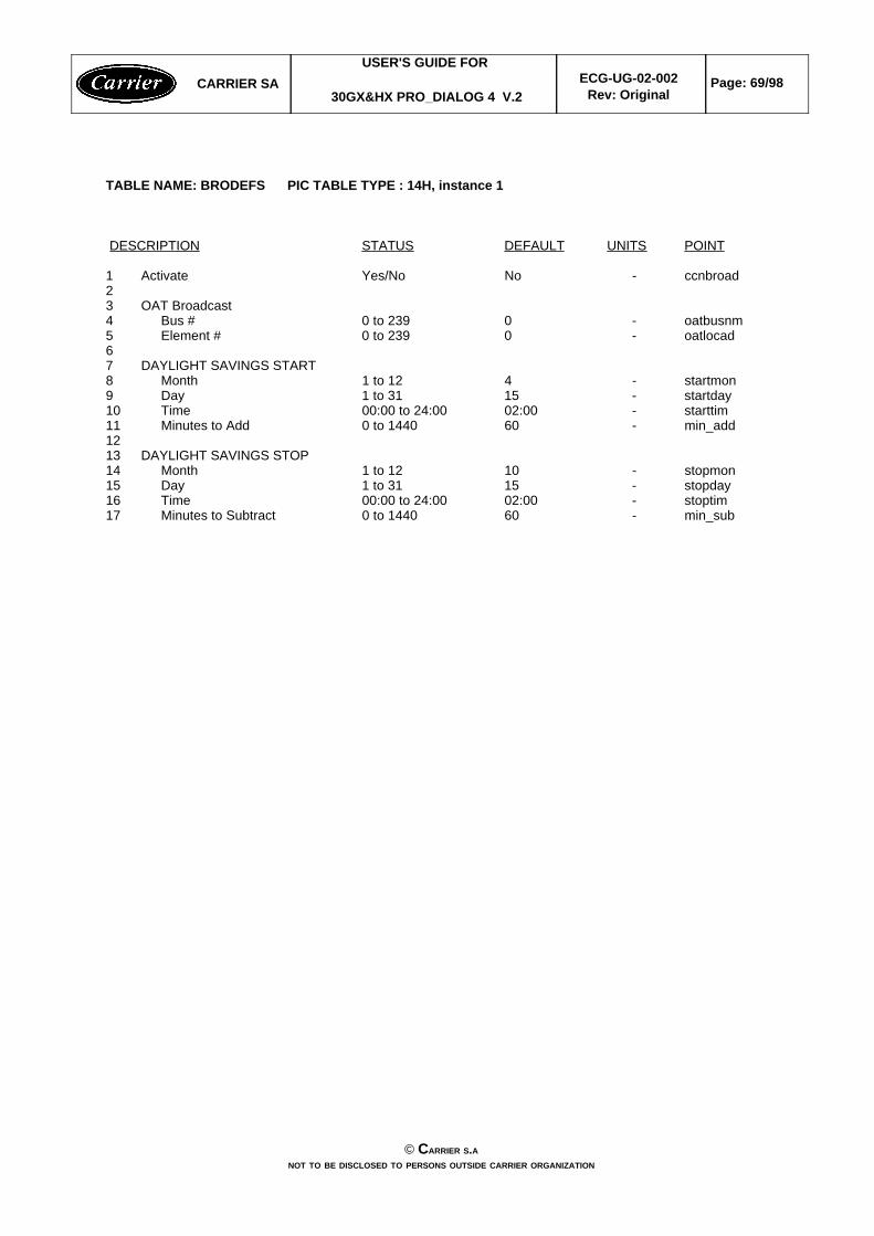
TABLE NAME: BRODEFS PIC TABLE TYPE : 14H, instance 1
DESCRIPTION STATUS DEFAULT UNITS POINT
1 Activate Yes/No No - ccnbroad23 OAT Broadcast4 Bus # 0 to 239 0 - oatbusnm5 Element # 0 to 239 0 - oatlocad67 DAYLIGHT SAVINGS START8 Month 1 to 12 4 - startmon9 Day 1 to 31 15 - startday10 Time 00:00 to 24:00 02:00 - starttim11 Minutes to Add 0 to 1440 60 - min_add1213 DAYLIGHT SAVINGS STOP14 Month 1 to 12 10 - stopmon15 Day 1 to 31 15 - stopday16 Time 00:00 to 24:00 02:00 - stoptim17 Minutes to Subtract 0 to 1440 60 - min_sub
CARRIER SAUSER'S GUIDE FOR
30GX&HX PRO_DIALOG 4 V.2ECG-UG-02-002
Rev: OriginalPage: 69/98
© CARRIER S.ANOT TO BE DISCLOSED TO PERSONS OUTSIDE CARRIER ORGANIZATION
CONFIGURATION SCREEN
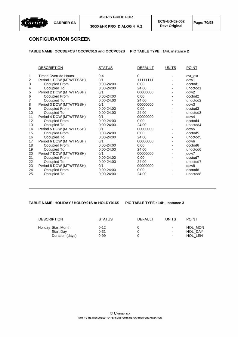
TABLE NAME: OCCDEFCS / OCCPC01S and OCCPC02S PIC TABLE TYPE : 14H, instance 2
DESCRIPTION STATUS DEFAULT UNITS POINT
1 Timed Override Hours 0-4 0 - ovr_ext2 Period 1 DOW (MTWTFSSH) 0/1 11111111 - dow13 Occupied From 0:00-24:00 0:00 - occtod14 Occupied To 0:00-24:00 24:00 - unoctod15 Period 2 DOW (MTWTFSSH) 0/1 00000000 - dow26 Occupied From 0:00-24:00 0:00 - occtod27 Occupied To 0:00-24:00 24:00 - unoctod28 Period 3 DOW (MTWTFSSH) 0/1 00000000 - dow39 Occupied From 0:00-24:00 0:00 - occtod310 Occupied To 0:00-24:00 24:00 - unoctod311 Period 4 DOW (MTWTFSSH) 0/1 00000000 - dow412 Occupied From 0:00-24:00 0:00 - occtod413 Occupied To 0:00-24:00 24:00 - unoctod414 Period 5 DOW (MTWTFSSH) 0/1 00000000 - dow515 Occupied From 0:00-24:00 0:00 - occtod516 Occupied To 0:00-24:00 24:00 - unoctod517 Period 6 DOW (MTWTFSSH) 0/1 00000000 - dow618 Occupied From 0:00-24:00 0:00 - occtod619 Occupied To 0:00-24:00 24:00 - unoctod620 Period 7 DOW (MTWTFSSH) 0/1 00000000 - dow721 Occupied From 0:00-24:00 0:00 - occtod722 Occupied To 0:00-24:00 24:00 - unoctod723 Period 8 DOW (MTWTFSSH) 0/1 00000000 - dow824 Occupied From 0:00-24:00 0:00 - occtod825 Occupied To 0:00-24:00 24:00 - unoctod8
TABLE NAME: HOLIDAY / HOLDY01S to HOLDY016S PIC TABLE TYPE : 14H, instance 3
DESCRIPTION STATUS DEFAULT UNITS POINT
Holiday Start Month 0-12 0 - HOL_MONStart Day 0-31 0 - HOL_DAYDuration (days) 0-99 0 - HOL_LEN
CARRIER SAUSER'S GUIDE FOR
30GX&HX PRO_DIALOG 4 V.2ECG-UG-02-002
Rev: OriginalPage: 70/98
© CARRIER S.ANOT TO BE DISCLOSED TO PERSONS OUTSIDE CARRIER ORGANIZATION
SETPOINT SCREEN
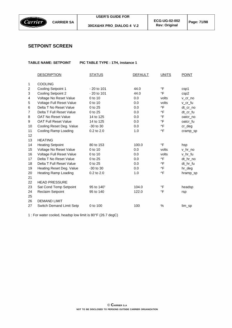
TABLE NAME: SETPOINT PIC TABLE TYPE : 17H, instance 1
DESCRIPTION STATUS DEFAULT UNITS POINT
1 COOLING2 Cooling Setpoint 1 - 20 to 101 44.0 °F csp13 Cooling Setpoint 2 - 20 to 101 44.0 °F csp24 Voltage No Reset Value 0 to 10 0.0 volts v_cr_no5 Voltage Full Reset Value 0 to 10 0.0 volts v_cr_fu6 Delta T No Reset Value 0 to 25 0.0 ^F dt_cr_no7 Delta T Full Reset Value 0 to 25 0.0 ^F dt_cr_fu8 OAT No Reset Value 14 to 125 0.0 °F oatcr_no9 OAT Full Reset Value 14 to 125 0.0 °F oatcr_fu10 Cooling Reset Deg. Value -30 to 30 0.0 ^F cr_deg11 Cooling Ramp Loading 0.2 to 2.0 1.0 ^F cramp_sp1213 HEATING14 Heating Setpoint 80 to 153 100.0 °F hsp15 Voltage No Reset Value 0 to 10 0.0 volts v_hr_no16 Voltage Full Reset Value 0 to 10 0.0 volts v_hr_fu17 Delta T No Reset Value 0 to 25 0.0 ^F dt_hr_no18 Delta T Full Reset Value 0 to 25 0.0 ^F dt_hr_fu19 Heating Reset Deg. Value -30 to 30 0.0 ^F hr_deg20 Heating Ramp Loading 0.2 to 2.0 1.0 ^F hramp_sp2122 HEAD PRESSURE23 Sat Cond Temp Setpoint 95 to 1401 104.0 °F headsp24 Reclaim Setpoint 95 to 140 122.0 °F rsp2526 DEMAND LIMIT27 Switch Demand Limit Setp 0 to 100 100 % lim_sp
1 : For water cooled, headsp low limit is 80°F (26.7 degC)
CARRIER SAUSER'S GUIDE FOR
30GX&HX PRO_DIALOG 4 V.2ECG-UG-02-002
Rev: OriginalPage: 71/98
© CARRIER S.ANOT TO BE DISCLOSED TO PERSONS OUTSIDE CARRIER ORGANIZATION
MAINTENANCE SCREEN
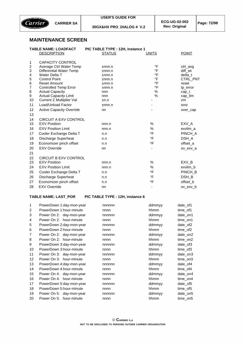
TABLE NAME: LOADFACT PIC TABLE TYPE : 12H, instance 1DESCRIPTION STATUS UNITS POINT
1 CAPACITY CONTROL2 Average Ctrl Water Temp ±nnn.n °F ctrl_avg3 Differential Water Temp ±nnn.n °F diff_wt4 Water Delta T ±nnn.n ^F delta_t5 Control Point ±nnn.n °F CTRL_PNT6 Reset Amount ±nnn.n ^F reset7 Controlled Temp Error ±nnn.n ^F tp_error8 Actual Capacity nnn % cap_t9 Actual Capacity Limit nnn % cap_lim10 Current Z Multiplier Val ±n.n - zm11 Load/Unload Factor ±nnn.n - smz12 Active Capacity Override nn - over_cap1314 CIRCUIT A EXV CONTROL15 EXV Position nnn.n % EXV_A16 EXV Position Limit nnn.n % exvlim_a17 Cooler Exchange Delta T n.n ^F PINCH_A18 Discharge Superheat n.n °F DSH_A19 Economizer pinch offset n.n ^F offset_a20 EXV Override nn - ov_exv_a2122 CIRCUIT B EXV CONTROL23 EXV Position nnn.n % EXV_B24 EXV Position Limit nnn.n % exvlim_b25 Cooler Exchange Delta T n.n ^F PINCH_B26 Discharge Superheat n.n °F DSH_B27 Economizer pinch offset n.n ^F offset_b28 EXV Override nn - ov_exv_b
TABLE NAME: LAST_POR PIC TABLE TYPE : 12H, instance 6
1 PowerDown 1:day-mon-year nnnnnn ddmmyy date_of12 PowerDown 1:hour-minute nnnn hhmm time_of13 Power On 2: day-mon-year nnnnnn ddmmyy date_on14 Power On 2: hour-minute nnnn hhmm time_on15 PowerDown 2:day-mon-year nnnnnn ddmmyy date_of26 PowerDown 2:hour-minute nnnn hhmm time_of27 Power On 2: day-mon-year nnnnnn ddmmyy date_on28 Power On 2: hour-minute nnnn hhmm time_on29 PowerDown 3:day-mon-year nnnnnn ddmmyy date_of310 PowerDown 3:hour-minute nnnn hhmm time_of311 Power On 3: day-mon-year nnnnnn ddmmyy date_on312 Power On 3: hour-minute nnnn hhmm time_on313 PowerDown 4:day-mon-year nnnnnn ddmmyy date_of414 PowerDown 4:hour-minute nnnn hhmm time_of415 Power On 4: day-mon-year nnnnnn ddmmyy date_on416 Power On 4: hour-minute nnnn hhmm time_on417 PowerDown 5:day-mon-year nnnnnn ddmmyy date_of518 PowerDown 5:hour-minute nnnn hhmm time_of519 Power On 5: day-mon-year nnnnnn ddmmyy date_on520 Power On 5: hour-minute nnnn hhmm time_on5
CARRIER SAUSER'S GUIDE FOR
30GX&HX PRO_DIALOG 4 V.2ECG-UG-02-002
Rev: OriginalPage: 72/98
© CARRIER S.ANOT TO BE DISCLOSED TO PERSONS OUTSIDE CARRIER ORGANIZATION
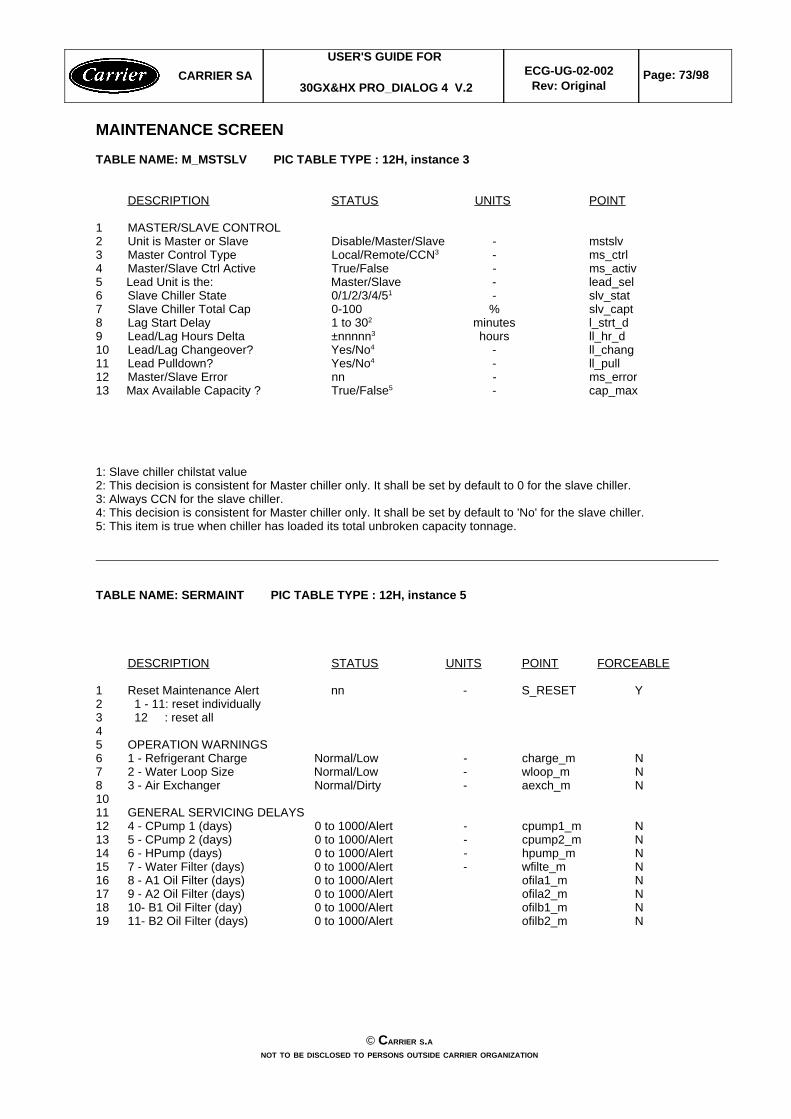
MAINTENANCE SCREEN
TABLE NAME: M_MSTSLV PIC TABLE TYPE : 12H, instance 3
DESCRIPTION STATUS UNITS POINT
1 MASTER/SLAVE CONTROL2 Unit is Master or Slave Disable/Master/Slave - mstslv3 Master Control Type Local/Remote/CCN3 - ms_ctrl4 Master/Slave Ctrl Active True/False - ms_activ5 Lead Unit is the: Master/Slave - lead_sel6 Slave Chiller State 0/1/2/3/4/51 - slv_stat7 Slave Chiller Total Cap 0-100 % slv_capt8 Lag Start Delay 1 to 302 minutes l_strt_d9 Lead/Lag Hours Delta ±nnnnn3 hours ll_hr_d10 Lead/Lag Changeover? Yes/No4 - ll_chang11 Lead Pulldown? Yes/No4 - ll_pull12 Master/Slave Error nn - ms_error13 Max Available Capacity ? True/False5 - cap_max
1: Slave chiller chilstat value2: This decision is consistent for Master chiller only. It shall be set by default to 0 for the slave chiller.3: Always CCN for the slave chiller.4: This decision is consistent for Master chiller only. It shall be set by default to 'No' for the slave chiller.5: This item is true when chiller has loaded its total unbroken capacity tonnage.
TABLE NAME: SERMAINT PIC TABLE TYPE : 12H, instance 5
DESCRIPTION STATUS UNITS POINT FORCEABLE
1 Reset Maintenance Alert nn - S_RESET Y2 1 - 11: reset individually3 12 : reset all45 OPERATION WARNINGS6 1 - Refrigerant Charge Normal/Low - charge_m N7 2 - Water Loop Size Normal/Low - wloop_m N8 3 - Air Exchanger Normal/Dirty - aexch_m N1011 GENERAL SERVICING DELAYS12 4 - CPump 1 (days) 0 to 1000/Alert - cpump1_m N13 5 - CPump 2 (days) 0 to 1000/Alert - cpump2_m N14 6 - HPump (days) 0 to 1000/Alert - hpump_m N15 7 - Water Filter (days) 0 to 1000/Alert - wfilte_m N16 8 - A1 Oil Filter (days) 0 to 1000/Alert ofila1_m N17 9 - A2 Oil Filter (days) 0 to 1000/Alert ofila2_m N18 10- B1 Oil Filter (day) 0 to 1000/Alert ofilb1_m N19 11- B2 Oil Filter (days) 0 to 1000/Alert ofilb2_m N
CARRIER SAUSER'S GUIDE FOR
30GX&HX PRO_DIALOG 4 V.2ECG-UG-02-002
Rev: OriginalPage: 73/98
© CARRIER S.ANOT TO BE DISCLOSED TO PERSONS OUTSIDE CARRIER ORGANIZATION
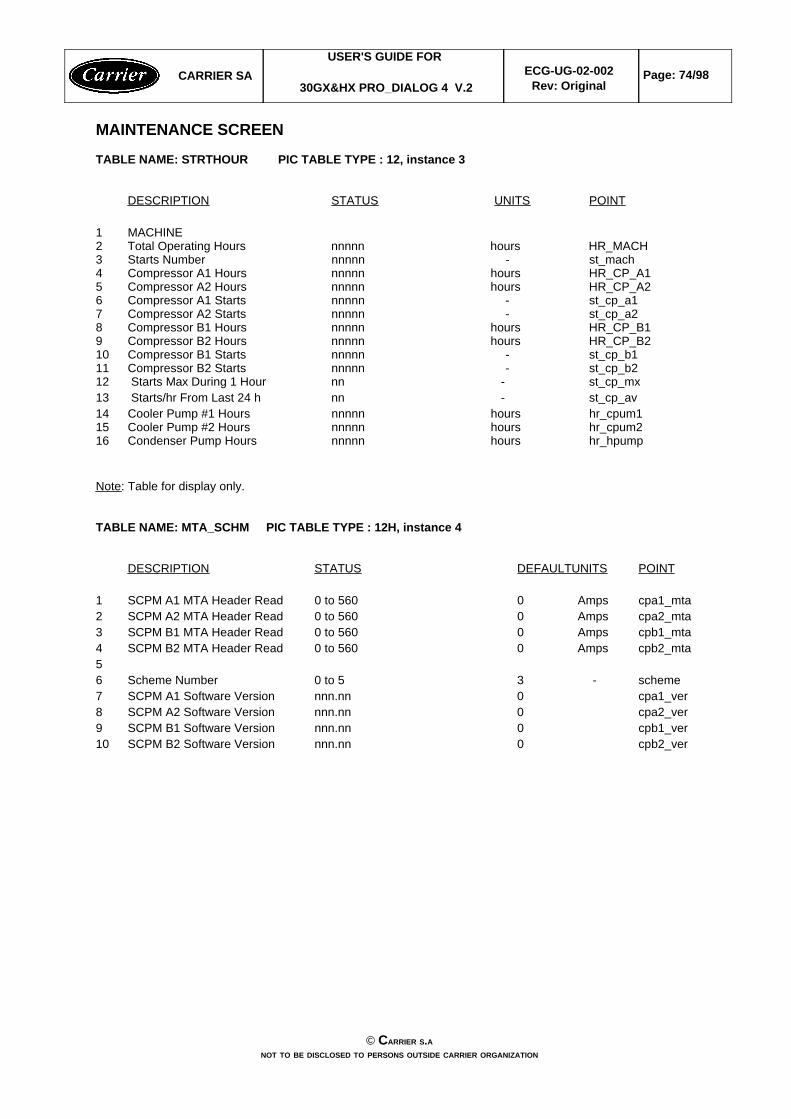
MAINTENANCE SCREEN
TABLE NAME: STRTHOUR PIC TABLE TYPE : 12, instance 3
DESCRIPTION STATUS UNITS POINT
1 MACHINE2 Total Operating Hours nnnnn hours HR_MACH3 Starts Number nnnnn - st_mach4 Compressor A1 Hours nnnnn hours HR_CP_A15 Compressor A2 Hours nnnnn hours HR_CP_A26 Compressor A1 Starts nnnnn - st_cp_a17 Compressor A2 Starts nnnnn - st_cp_a28 Compressor B1 Hours nnnnn hours HR_CP_B19 Compressor B2 Hours nnnnn hours HR_CP_B210 Compressor B1 Starts nnnnn - st_cp_b111 Compressor B2 Starts nnnnn - st_cp_b212 Starts Max During 1 Hour nn - st_cp_mx13 Starts/hr From Last 24 h nn - st_cp_av14 Cooler Pump #1 Hours nnnnn hours hr_cpum115 Cooler Pump #2 Hours nnnnn hours hr_cpum216 Condenser Pump Hours nnnnn hours hr_hpump
Note: Table for display only.
TABLE NAME: MTA_SCHM PIC TABLE TYPE : 12H, instance 4
DESCRIPTION STATUS DEFAULTUNITS POINT
1 SCPM A1 MTA Header Read 0 to 560 0 Amps cpa1_mta2 SCPM A2 MTA Header Read 0 to 560 0 Amps cpa2_mta3 SCPM B1 MTA Header Read 0 to 560 0 Amps cpb1_mta4 SCPM B2 MTA Header Read 0 to 560 0 Amps cpb2_mta56 Scheme Number 0 to 5 3 - scheme7 SCPM A1 Software Version nnn.nn 0 cpa1_ver8 SCPM A2 Software Version nnn.nn 0 cpa2_ver9 SCPM B1 Software Version nnn.nn 0 cpb1_ver10 SCPM B2 Software Version nnn.nn 0 cpb2_ver
CARRIER SAUSER'S GUIDE FOR
30GX&HX PRO_DIALOG 4 V.2ECG-UG-02-002
Rev: OriginalPage: 74/98
© CARRIER S.ANOT TO BE DISCLOSED TO PERSONS OUTSIDE CARRIER ORGANIZATION
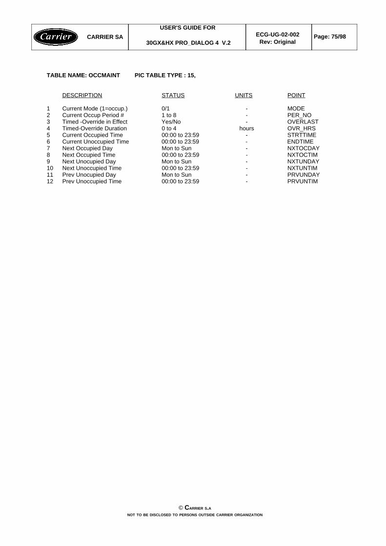
TABLE NAME: OCCMAINT PIC TABLE TYPE : 15,
DESCRIPTION STATUS UNITS POINT
1 Current Mode (1=occup.) 0/1 - MODE2 Current Occup Period # 1 to 8 - PER_NO3 Timed -Override in Effect Yes/No - OVERLAST4 Timed-Override Duration 0 to 4 hours OVR_HRS5 Current Occupied Time 00:00 to 23:59 - STRTTIME6 Current Unoccupied Time 00:00 to 23:59 - ENDTIME7 Next Occupied Day Mon to Sun - NXTOCDAY8 Next Occupied Time 00:00 to 23:59 - NXTOCTIM9 Next Unocupied Day Mon to Sun - NXTUNDAY10 Next Unoccupied Time 00:00 to 23:59 - NXTUNTIM11 Prev Unocupied Day Mon to Sun - PRVUNDAY12 Prev Unoccupied Time 00:00 to 23:59 - PRVUNTIM
CARRIER SAUSER'S GUIDE FOR
30GX&HX PRO_DIALOG 4 V.2ECG-UG-02-002
Rev: OriginalPage: 75/98
© CARRIER S.ANOT TO BE DISCLOSED TO PERSONS OUTSIDE CARRIER ORGANIZATION
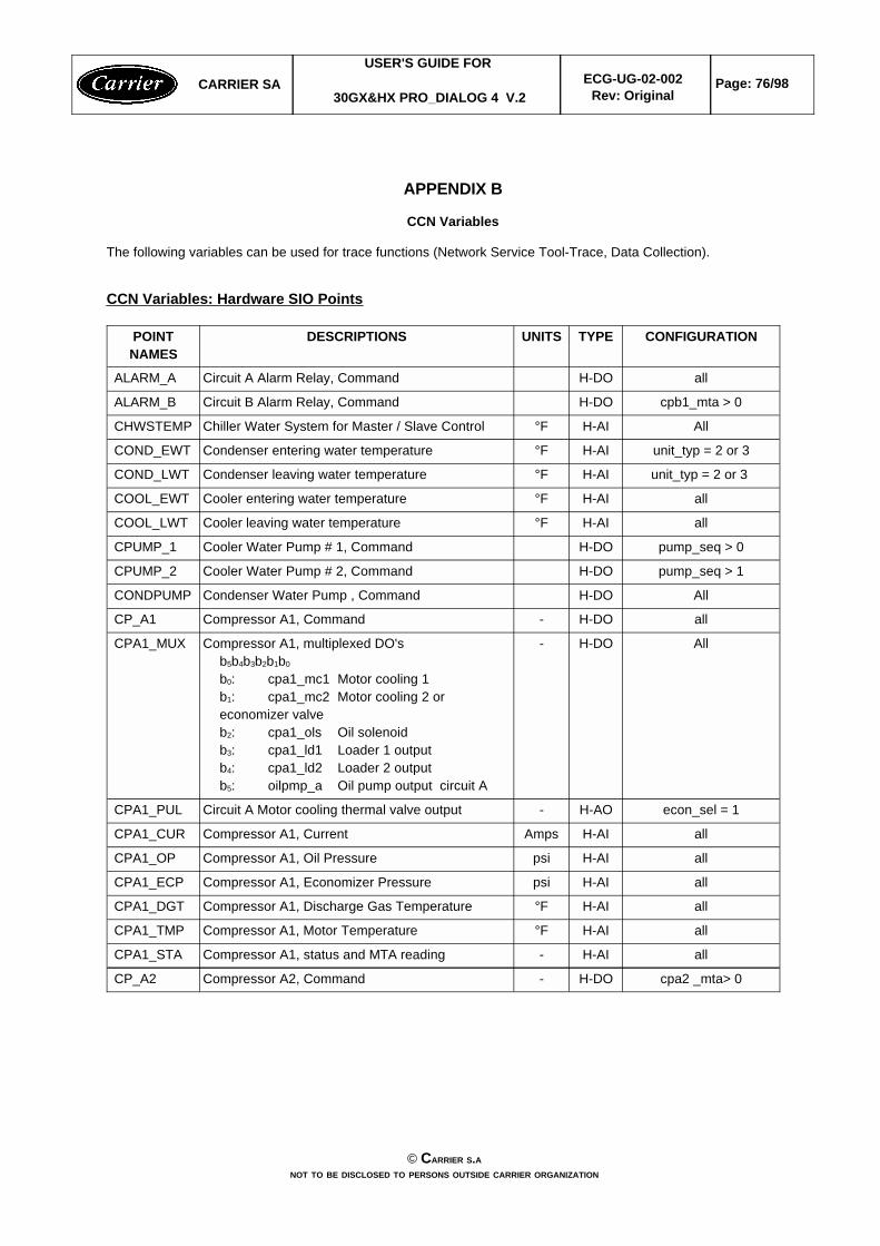
APPENDIX B
CCN Variables
The following variables can be used for trace functions (Network Service Tool-Trace, Data Collection).
CCN Variables: Hardware SIO Points
cpa2 _mta> 0H-DO-Compressor A2, CommandCP_A2
allH-AI-Compressor A1, status and MTA reading CPA1_STA
allH-AI°FCompressor A1, Motor Temperature CPA1_TMP
allH-AI°FCompressor A1, Discharge Gas TemperatureCPA1_DGT
allH-AIpsiCompressor A1, Economizer PressureCPA1_ECP
allH-AIpsiCompressor A1, Oil PressureCPA1_OP
allH-AIAmpsCompressor A1, Current CPA1_CUR
econ_sel = 1H-AO-Circuit A Motor cooling thermal valve outputCPA1_PUL
AllH-DO-Compressor A1, multiplexed DO'sb5b4b3b2b1b0 b0: cpa1_mc1 Motor cooling 1b1: cpa1_mc2 Motor cooling 2 oreconomizer valveb2: cpa1_ols Oil solenoidb3: cpa1_ld1 Loader 1 outputb4: cpa1_ld2 Loader 2 output b5: oilpmp_a Oil pump output circuit A
CPA1_MUX
allH-DO-Compressor A1, CommandCP_A1
AllH-DOCondenser Water Pump , CommandCONDPUMP
pump_seq > 1H-DOCooler Water Pump # 2, CommandCPUMP_2
pump_seq > 0H-DOCooler Water Pump # 1, CommandCPUMP_1
allH-AI°FCooler leaving water temperatureCOOL_LWT
allH-AI°FCooler entering water temperatureCOOL_EWT
unit_typ = 2 or 3 H-AI°FCondenser leaving water temperatureCOND_LWT
unit_typ = 2 or 3H-AI°FCondenser entering water temperatureCOND_EWT
AllH-AI°FChiller Water System for Master / Slave ControlCHWSTEMP
cpb1_mta > 0H-DOCircuit B Alarm Relay, CommandALARM_B
allH-DOCircuit A Alarm Relay, CommandALARM_A
CONFIGURATIONTYPEUNITSDESCRIPTIONSPOINTNAMES
CARRIER SAUSER'S GUIDE FOR
30GX&HX PRO_DIALOG 4 V.2ECG-UG-02-002
Rev: OriginalPage: 76/98
© CARRIER S.ANOT TO BE DISCLOSED TO PERSONS OUTSIDE CARRIER ORGANIZATION
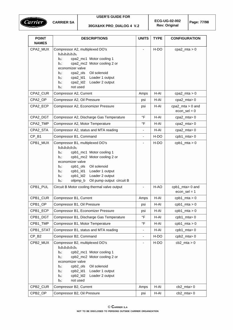
cb2_mta> 0H-AIpsiCompressor B2, Oil PressureCPB2_OP
cb2_mta> 0H-AIAmpsCompressor B2, Current CPB2_CUR
cb2_mta > 0H-DO-Compressor B2, multiplexed DO'sb5b4b3b2b1b0 b0: cpb2_mc1 Motor cooling 1b1: cpb2_mc2 Motor cooling 2 oreconomizer valveb2: cpb2_ols Oil solenoidb3: cpb2_ld1 Loader 1 outputb4: cpb2_ld2 Loader 2 output b5: not used
CPB2_MUX
cpb2_mta> 0H-DO-Compressor B2, CommandCP_B2
cpb1_mta> 0H-AI-Compressor B1, status and MTA reading CPB1_STAT
cpb1_mta > 0H-AI°FCompressor B1, Motor Temperature CPB1_TMP
cpb1_mta> 0H-AI°FCompressor B1, Discharge Gas TemperatureCPB1_DGT
cpb1_mta > 0H-AIpsiCompressor B1, Economizer PressureCPB1_ECP
cpb1_mta > 0H-AIpsiCompressor B1, Oil PressureCPB1_OP
cpb1_mta > 0H-AIAmpsCompressor B1, Current CPB1_CUR
cpb1_mta> 0 andecon_sel = 1
H-AO-Circuit B Motor cooling thermal valve outputCPB1_PUL
cpb1_mta > 0H-DO-Compressor B1, multiplexed DO'sb5b4b3b2b1b0 b0: cpb1_mc1 Motor cooling 1b1: cpb1_mc2 Motor cooling 2 oreconomizer valveb2: cpb1_ols Oil solenoidb3: cpb1_ld1 Loader 1 outputb4: cpb1_ld2 Loader 2 output b5: oilpmp_b Oil pump output circuit B
CPB1_MUX
cpb1_mta> 0H-DO-Compressor B1, CommandCP_B1
cpa2_mta> 0H-AI-Compressor A2, status and MTA reading CPA2_STA
cpa2_mta> 0H-AI°FCompressor A2, Motor Temperature CPA2_TMP
cpa2_mta> 0H-AI°FCompressor A2, Discharge Gas TemperatureCPA2_DGT
cpa2_mta > 0 andecon_sel = 0
H-AIpsiCompressor A2, Economizer PressureCPA2_ECP
cpa2_mta> 0H-AIpsiCompressor A2, Oil PressureCPA2_OP
cpa2_mta > 0H-AIAmpsCompressor A2, Current CPA2_CUR
cpa2_mta > 0H-DO-Compressor A2, multiplexed DO'sb5b4b3b2b1b0 b0: cpa2_mc1 Motor cooling 1b1: cpa2_mc2 Motor cooling 2 oreconomizer valveb2: cpa2_ols Oil solenoidb3: cpa2_ld1 Loader 1 outputb4: cpa2_ld2 Loader 2 output b5: not used
CPA2_MUX
CONFIGURATIONTYPEUNITSDESCRIPTIONSPOINTNAMES
CARRIER SAUSER'S GUIDE FOR
30GX&HX PRO_DIALOG 4 V.2ECG-UG-02-002
Rev: OriginalPage: 77/98
© CARRIER S.ANOT TO BE DISCLOSED TO PERSONS OUTSIDE CARRIER ORGANIZATION

all
(all)(all)
(unit_typ = 3)(unit_typ = 1 or 4)
(all)(all)(all)(all)
(uni_typ = 1 or 4)
H-DIM-Basic board multilexed DI's:b7b6b5b4b3b2b1b0
b0: onoff_sw Remote on/off switchb1: spt_sw Remote dual setpoint swb2: hc_sw Remote heat/cool switchb2: recl_sw Remote reclaim swutchb3: limit_sw demand limit switch b4: lock_1 Cooler interlock b5: elec_box Electrical Box Thermostatb6: condflow Condenser flow switchb7: pump_def Pump default
MUX_DI
econ_sel and tq_r_fbk=YES
H-AI-Motor Cooling Feedback Signal circuit B MTQ_RESB
econ_sel and tq_r_fbk=YES
H-AI-Motor Cooling Feedback Signal circuit A MTQ_RESA
recl_opt = 1H-AO0 -10Vdc
Reclaim Condenser Water ValveHR_WTRVL
hr_tmp = 1H-AI°FReclaim Entering Water TemperatureHR_LWT
hr_tmp = 1H-AI°FReclaim Entering Water TemperatureHR_EWT
hd_selec > 0H-AO4 - 20mA0 -
10Vdc
Varifan or Water Valve Circuit BHD_B
hd_selec > 0H-AO4 - 20mA0 -
10Vdc
Varifan or Water Valve Circuit AHD_A
cb2_mta> 0H-AIpsiDischarge Pressure Circuit BDP_B
allH-AIpsiDischarge Pressure Circuit ADP_A
allH-AIvoltsExternal 0 - 10 Vdc input sensor EXT_VDC
cb2_mta > 0H-AO%EXV Movement Circuit BEXV_ST_B
allH-AO%EXV Movement Circuit AEXV_ST_A
cb2_mta> 0H-AI-Compressor B2, status and MTA reading CPB2_STA
cb2_mta> 0H-AI°FCompressor B2, Motor Temperature CPB2_TMP
cb2_mta> 0H-AI°FCompressor B2, Discharge Gas TemperatureCPB2_DGT
cb2_mta > 0 andecon_sel = 0
H-AIpsiCompressor B2, Economizer PressureCPB2_ECP
CONFIGURATIONTYPEUNITSDESCRIPTIONSPOINTNAMES
CARRIER SAUSER'S GUIDE FOR
30GX&HX PRO_DIALOG 4 V.2ECG-UG-02-002
Rev: OriginalPage: 78/98
© CARRIER S.ANOT TO BE DISCLOSED TO PERSONS OUTSIDE CARRIER ORGANIZATION
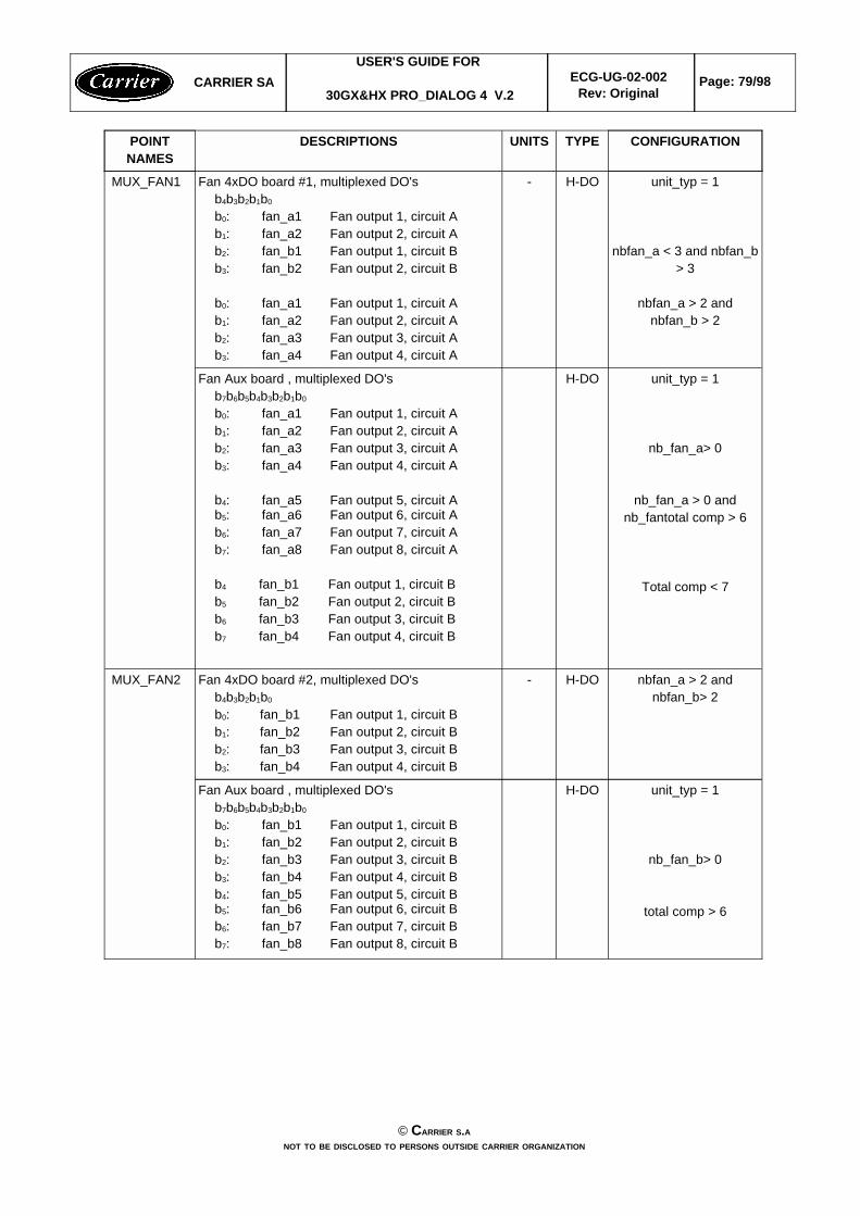
unit_typ = 1
nb_fan_b> 0
total comp > 6
H-DOFan Aux board , multiplexed DO'sb7b6b5b4b3b2b1b0 b0: fan_b1 Fan output 1, circuit Bb1: fan_b2 Fan output 2, circuit Bb2: fan_b3 Fan output 3, circuit Bb3: fan_b4 Fan output 4, circuit Bb4: fan_b5 Fan output 5, circuit Bb5: fan_b6 Fan output 6, circuit Bb6: fan_b7 Fan output 7, circuit Bb7: fan_b8 Fan output 8, circuit B
nbfan_a > 2 andnbfan_b> 2
H-DO-Fan 4xDO board #2, multiplexed DO'sb4b3b2b1b0 b0: fan_b1 Fan output 1, circuit Bb1: fan_b2 Fan output 2, circuit Bb2: fan_b3 Fan output 3, circuit Bb3: fan_b4 Fan output 4, circuit B
MUX_FAN2
unit_typ = 1
nb_fan_a> 0
nb_fan_a > 0 andnb_fantotal comp > 6
Total comp < 7
H-DOFan Aux board , multiplexed DO'sb7b6b5b4b3b2b1b0 b0: fan_a1 Fan output 1, circuit Ab1: fan_a2 Fan output 2, circuit Ab2: fan_a3 Fan output 3, circuit Ab3: fan_a4 Fan output 4, circuit A
b4: fan_a5 Fan output 5, circuit Ab5: fan_a6 Fan output 6, circuit Ab6: fan_a7 Fan output 7, circuit Ab7: fan_a8 Fan output 8, circuit A
b4 fan_b1 Fan output 1, circuit Bb5 fan_b2 Fan output 2, circuit Bb6 fan_b3 Fan output 3, circuit Bb7 fan_b4 Fan output 4, circuit B
unit_typ = 1
nbfan_a < 3 and nbfan_b> 3
nbfan_a > 2 andnbfan_b > 2
H-DO-Fan 4xDO board #1, multiplexed DO'sb4b3b2b1b0 b0: fan_a1 Fan output 1, circuit Ab1: fan_a2 Fan output 2, circuit Ab2: fan_b1 Fan output 1, circuit Bb3: fan_b2 Fan output 2, circuit B
b0: fan_a1 Fan output 1, circuit Ab1: fan_a2 Fan output 2, circuit Ab2: fan_a3 Fan output 3, circuit Ab3: fan_a4 Fan output 4, circuit A
MUX_FAN1
CONFIGURATIONTYPEUNITSDESCRIPTIONSPOINTNAMES
CARRIER SAUSER'S GUIDE FOR
30GX&HX PRO_DIALOG 4 V.2ECG-UG-02-002
Rev: OriginalPage: 79/98
© CARRIER S.ANOT TO BE DISCLOSED TO PERSONS OUTSIDE CARRIER ORGANIZATION
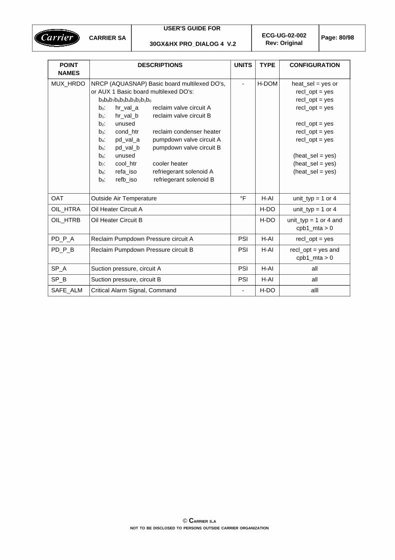
alllH-DO-Critical Alarm Signal, CommandSAFE_ALM
allH-AIPSISuction pressure, circuit BSP_B
allH-AIPSISuction pressure, circuit ASP_A
recl_opt = yes andcpb1_mta > 0
H-AIPSIReclaim Pumpdown Pressure circuit BPD_P_B
recl_opt = yesH-AIPSIReclaim Pumpdown Pressure circuit APD_P_A
unit_typ = 1 or 4 andcpb1_mta > 0
H-DOOil Heater Circuit BOIL_HTRB
unit_typ = 1 or 4H-DOOil Heater Circuit AOIL_HTRA
unit_typ = 1 or 4H-AI°FOutside Air TemperatureOAT
heat_sel = yes orrecl_opt = yesrecl_opt = yesrecl_opt = yes
recl_opt = yesrecl_opt = yesrecl_opt = yes
(heat_sel = yes)(heat_sel = yes)(heat_sel = yes)
H-DOM-NRCP (AQUASNAP) Basic board multilexed DO's,or AUX 1 Basic board multilexed DO's:
b9b8b7b6b5b4b3b2b1b0
b0: hr_val_a reclaim valve circuit Ab1: hr_val_b reclaim valve circuit Bb2: unusedb3: cond_htr reclaim condenser heaterb4: pd_val_a pumpdown valve circuit Ab5: pd_val_b pumpdown valve circuit Bb6: unusedb7: cool_htr cooler heaterb8: refa_iso refriegerant solenoid Ab9: refb_iso refriegerant solenoid B
MUX_HRDO
CONFIGURATIONTYPEUNITSDESCRIPTIONSPOINTNAMES
CARRIER SAUSER'S GUIDE FOR
30GX&HX PRO_DIALOG 4 V.2ECG-UG-02-002
Rev: OriginalPage: 80/98
© CARRIER S.ANOT TO BE DISCLOSED TO PERSONS OUTSIDE CARRIER ORGANIZATION
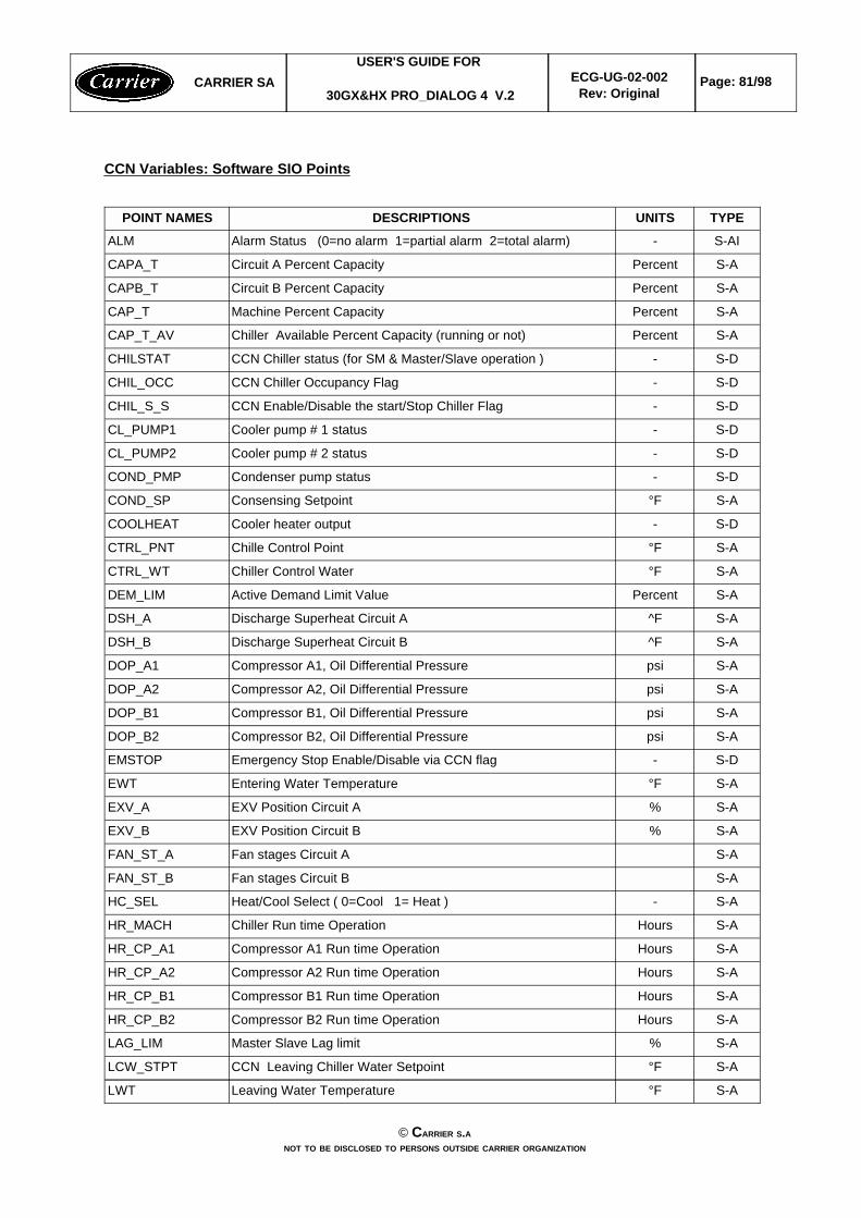
CCN Variables: Software SIO Points
S-A°FLeaving Water TemperatureLWT
S-A°FCCN Leaving Chiller Water SetpointLCW_STPT
S-A%Master Slave Lag limitLAG_LIM
S-AHoursCompressor B2 Run time Operation HR_CP_B2
S-AHoursCompressor B1 Run time Operation HR_CP_B1
S-AHoursCompressor A2 Run time Operation HR_CP_A2
S-AHoursCompressor A1 Run time Operation HR_CP_A1
S-AHoursChiller Run time Operation HR_MACH
S-A-Heat/Cool Select ( 0=Cool 1= Heat )HC_SEL
S-AFan stages Circuit BFAN_ST_B
S-AFan stages Circuit AFAN_ST_A
S-A%EXV Position Circuit BEXV_B
S-A%EXV Position Circuit AEXV_A
S-A°FEntering Water TemperatureEWT
S-D-Emergency Stop Enable/Disable via CCN flagEMSTOP
S-ApsiCompressor B2, Oil Differential Pressure DOP_B2
S-ApsiCompressor B1, Oil Differential Pressure DOP_B1
S-ApsiCompressor A2, Oil Differential Pressure DOP_A2
S-ApsiCompressor A1, Oil Differential Pressure DOP_A1
S-A^FDischarge Superheat Circuit BDSH_B
S-A^FDischarge Superheat Circuit ADSH_A
S-APercentActive Demand Limit ValueDEM_LIM
S-A°FChiller Control Water CTRL_WT
S-A°FChille Control PointCTRL_PNT
S-D-Cooler heater outputCOOLHEAT
S-A°FConsensing SetpointCOND_SP
S-D-Condenser pump statusCOND_PMP
S-D-Cooler pump # 2 statusCL_PUMP2
S-D-Cooler pump # 1 statusCL_PUMP1
S-D-CCN Enable/Disable the start/Stop Chiller FlagCHIL_S_S
S-D-CCN Chiller Occupancy FlagCHIL_OCC
S-D-CCN Chiller status (for SM & Master/Slave operation )CHILSTAT
S-APercentChiller Available Percent Capacity (running or not)CAP_T_AV
S-APercentMachine Percent CapacityCAP_T
S-APercentCircuit B Percent CapacityCAPB_T
S-APercentCircuit A Percent CapacityCAPA_T
S-AI-Alarm Status (0=no alarm 1=partial alarm 2=total alarm) ALM
TYPEUNITSDESCRIPTIONSPOINT NAMES
CARRIER SAUSER'S GUIDE FOR
30GX&HX PRO_DIALOG 4 V.2ECG-UG-02-002
Rev: OriginalPage: 81/98
© CARRIER S.ANOT TO BE DISCLOSED TO PERSONS OUTSIDE CARRIER ORGANIZATION
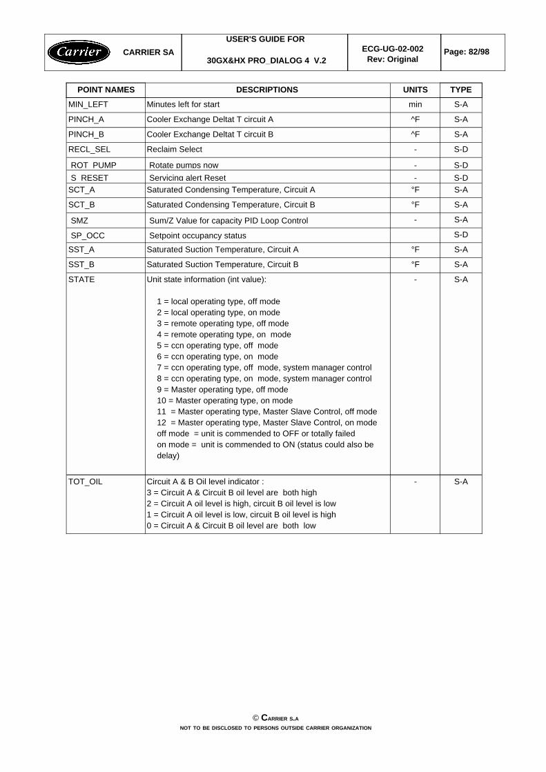
S-A-Circuit A & B Oil level indicator : 3 = Circuit A & Circuit B oil level are both high2 = Circuit A oil level is high, circuit B oil level is low1 = Circuit A oil level is low, circuit B oil level is high0 = Circuit A & Circuit B oil level are both low
TOT_OIL
S-A-Unit state information (int value):
1 = local operating type, off mode2 = local operating type, on mode3 = remote operating type, off mode4 = remote operating type, on mode5 = ccn operating type, off mode6 = ccn operating type, on mode7 = ccn operating type, off mode, system manager control8 = ccn operating type, on mode, system manager control9 = Master operating type, off mode10 = Master operating type, on mode11 = Master operating type, Master Slave Control, off mode12 = Master operating type, Master Slave Control, on modeoff mode = unit is commended to OFF or totally failedon mode = unit is commended to ON (status could also bedelay)
STATE
S-A°FSaturated Suction Temperature, Circuit BSST_B
S-A°FSaturated Suction Temperature, Circuit ASST_A
S-DSetpoint occupancy statusSP_OCC
S-A-Sum/Z Value for capacity PID Loop ControlSMZ
S-A°FSaturated Condensing Temperature, Circuit BSCT_B
S-A°FSaturated Condensing Temperature, Circuit ASCT_AS-D-Servicing alert ResetS RESETS-D-Rotate pumps nowROT PUMP
S-D-Reclaim SelectRECL_SEL
S-A^FCooler Exchange Deltat T circuit BPINCH_B
S-A^FCooler Exchange Deltat T circuit APINCH_A
S-AminMinutes left for startMIN_LEFT
TYPEUNITSDESCRIPTIONSPOINT NAMES
CARRIER SAUSER'S GUIDE FOR
30GX&HX PRO_DIALOG 4 V.2ECG-UG-02-002
Rev: OriginalPage: 82/98
© CARRIER S.ANOT TO BE DISCLOSED TO PERSONS OUTSIDE CARRIER ORGANIZATION
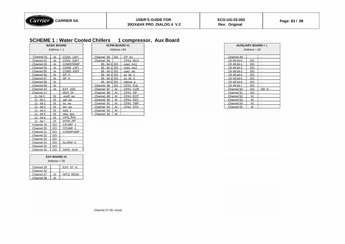
SCHEME 1 : Water Cooled Chillers 1 compressor, Aux Board
Channel 27-28: virtual
-AIChannel 38-MTQ RESAAIChannel 37-Channel 33EXV ST AChannel 29
EXV BOARD #1Address = 29
SAFE ALMDOChannel 26DOChannel 25
ALARM ADOChannel 24-DOChannel 23-DOChannel 22CONDPUMPDOChannel 21CPUMP 2DOChannel 20CPUMP 1DOChannel 19pump_defDI11 - bit 7cond_flowDI11 - bit 6
-AIChannel 94elec boxDI11 - bit 5 -AIChannel 93lock 1DI11 - bit 4
-AIChannel 55CPA1 STAAIChannel 92lim swDI11 - bit 3-AIChannel 54CPA1 TMPAIChannel 91hc swDI11 - bit 2-AIChannel 53CPA1 DGTAIChannel 90spt swDI11 - bit 1-AIChannel 52CPA1 ECPAIChannel 89onoff swDI11- bit 0
AOChannel 51CPA1 OPAIChannel 88MUX DI 1Channel 11HD AAOChannel 50CPA1 CURAIChannel 87EXT VDCAIChannel 10-DOCh 49 bit-7CPA1 PULDOChannel 86AIChannel 09-DOCh 49 bit-6oilpmp aDO85 - bit 5AIChannel 08-DOCh 49 bit-5a1 ldr 2DO85 - bit 4SP AAIChannel 07-DOCh 49 bit-4a1 ldr 1DO85 - bit 3DP AAIChannel 06-DOCh 49 bit-3cpa1 olsDO85 - bit 2COND EWTAIChannel 05-DOCh 49 bit-2cpa1 mc2DO85 - bit 1COND LWTAIChannel 04-DOCh 49 bit-1cpa1 mc1DO85 - bit 0CHWSTEMPAIChannel 03-DOCh 49 bit-0CPA1 MUXChannel 85COOL EWTAIChannel 02-Channel 49CP A1DOChannel 84COOL LWTAIChannel 01
AUXILIARY BOARD # 1 Address = 49
SCPM BOARD #1Address =84
BASIC BOARDAddress = 1
CARRIER SA USER’S GUIDE FOR 30GX&HX PRO_DIALOG 4 V.2
ECG-UG-02-002Rev: Original
Page: 83 / 98
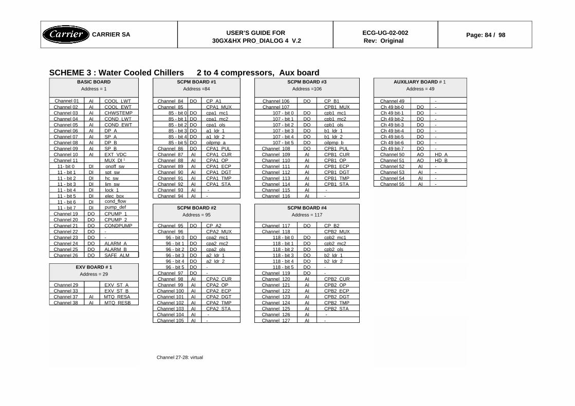
SCHEME 3 : Water Cooled Chillers 2 to 4 compressors, Aux board
Channel 27-28: virtual
-AIChannel 127-AIChannel 105 -AIChannel 126 -AIChannel 104CPB2 STAAIChannel 125CPA2 STAAIChannel 103CPB2 TMPAIChannel 124CPA2 TMPAIChannel 102MTQ RESBAIChannel 38CPB2 DGTAIChannel 123CPA2 DGTAIChannel 101MTQ RESAAIChannel 37CPB2 ECPAIChannel 122CPA2 ECPAIChannel 100EXV ST BChannel 33CPB2 OPAIChannel 121CPA2 OPAIChannel 99EXV ST AChannel 29CPB2 CURAIChannel 120CPA2 CURAIChannel 98-DOChannel 119-DOChannel 97-DO118 - bit 5-DO96 - bit 5EXV BOARD # 1
Address = 29
b2 ldr 2DO118 - bit 4a2 ldr 2DO96 - bit 4b2 ldr 1DO118 - bit 3a2 ldr 1DO96 - bit 3SAFE ALMDOChannel 26cpb2 olsDO118 - bit 2cpa2 olsDO96 - bit 2ALARM BDOChannel 25cpb2 mc2DO118 - bit 1cpa2 mc2DO96 - bit 1ALARM ADOChannel 24cpb2 mc1DO118 - bit 0cpa2 mc1DO96 - bit 0-DOChannel 23CPB2 MUXChannel 118CPA2 MUXChannel 96-DOChannel 22CP B2DOChannel 117CP A2DOChannel 95CONDPUMPDOChannel 21
CPUMP 2DOChannel 20CPUMP 1DOChannel 19
SCPM BOARD #4Address = 117
SCPM BOARD #2Address = 95
pump_defDI11 - bit 7cond_flowDI11 - bit 6
-AIChannel 116-AIChannel 94elec boxDI11 - bit 5 -AIChannel 115 -AIChannel 93lock 1DI11 - bit 4
-AIChannel 55CPB1 STAAIChannel 114CPA1 STAAIChannel 92lim swDI11 - bit 3-AIChannel 54CPB1 TMPAIChannel 113CPA1 TMPAIChannel 91hc swDI11 - bit 2-AIChannel 53CPB1 DGTAIChannel 112CPA1 DGTAIChannel 90spt swDI11 - bit 1-AIChannel 52CPB1 ECPAIChannel 111CPA1 ECPAIChannel 89onoff swDI11- bit 0HD BAOChannel 51CPB1 OPAIChannel 110CPA1 OPAIChannel 88MUX DI 1Channel 11HD AAOChannel 50CPB1 CURAIChannel 109CPA1 CURAIChannel 87EXT VDCAIChannel 10-DOCh 49 bit-7CPB1 PULDOChannel 108CPA1 PULDOChannel 86SP BAIChannel 09-DOCh 49 bit-6oilpmp bDO107 - bit 5oilpmp aDO85 - bit 5DP BAIChannel 08-DOCh 49 bit-5b1 ldr 2DO107 - bit 4a1 ldr 2DO85 - bit 4SP AAIChannel 07-DOCh 49 bit-4b1 ldr 1DO107 - bit 3a1 ldr 1DO85 - bit 3DP AAIChannel 06-DOCh 49 bit-3cpb1 olsDO107 - bit 2cpa1 olsDO85 - bit 2COND EWTAIChannel 05-DOCh 49 bit-2cpb1 mc2DO107 - bit 1cpa1 mc2DO85 - bit 1COND LWTAIChannel 04-DOCh 49 bit-1cpb1 mc1DO107 - bit 0cpa1 mc1DO85 - bit 0CHWSTEMPAIChannel 03-DOCh 49 bit-0CPB1 MUXChannel 107CPA1 MUXChannel 85COOL EWTAIChannel 02-Channel 49CP B1DOChannel 106CP A1DOChannel 84COOL LWTAIChannel 01
AUXILIARY BOARD # 1 Address = 49
SCPM BOARD #3Address =106
SCPM BOARD #1Address =84
BASIC BOARDAddress = 1
CARRIER SA USER’S GUIDE FOR 30GX&HX PRO_DIALOG 4 V.2
ECG-UG-02-002Rev: Original
Page: 84 / 98
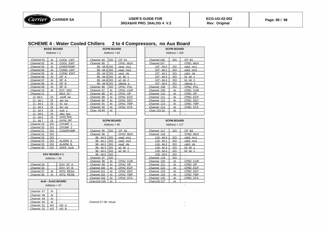
SCHEME 4 : Water Cooled Chillers 2 to 4 Compressors, no Aux Board
HD BAOChannel 52-HD AAOChannel 51-Channel 27-28: virtual -AIChannel 50
-AIChannel 49-AIChannel 48-AIChannel 47
- -AIChan126-127 -AIChan104-1054xAI - 2xAO BOARD
Address = 47
CPB2 STAAIChannel 125CPA2 STAAIChannel 103CPB2 TMPAIChannel 124CPA2 TMPAIChannel 102MTQ RESBAIChannel 38CPB2 DGTAIChannel 123CPA2 DGTAIChannel 101MTQ RESAAIChannel 37CPB2 ECPAIChannel 122CPA2 ECPAIChannel 100EXV ST BChannel 33CPB2 OPAIChannel 121CPA2 OPAIChannel 99EXV ST AChannel 29CPB2 CURAIChannel 120CPA2 CURAIChannel 98-DOChannel 119-DOChannel 97-DO118 - bit 5-DO96 - bit 5EXV BOARD # 1
Address = 29
b2 ldr 2DO118 - bit 4a2 ldr 2DO96 - bit 4b2 ldr 1DO118 - bit 3a2 ldr 1DO96 - bit 3SAFE ALMDOChannel 26cpb2 olsDO118 - bit 2cpa2 olsDO96 - bit 2ALARM BDOChannel 25cpb2 mc2DO118 - bit 1cpa2 mc2DO96 - bit 1ALARM ADOChannel 24cpb2 mc1DO118 - bit 0cpa2 mc1DO96 - bit 0-DOChannel 23CPB2 MUXChannel 118CPA2 MUXChannel 96-DOChannel 22CP B2DOChannel 117CP A2DOChannel 95CONDPUMPDOChannel 21
CPUMP 2DOChannel 20CPUMP 1DOChannel 19
SCPM BOARDAddress = 117
SCPM BOARDAddress = 40
pump_defDI11 - bit 7cond_flowDI11 - bit 6
--elec boxDI11 - bit 5 -AIChan 115-16 -AIChan 93-94lock 1DI11 - bit 4CPB1 STAAIChannel 114CPA1 STAAIChannel 92lim swDI11 - bit 3CPB1 TMPAIChannel 113CPA1 TMPAIChannel 91hc swDI11 - bit 2CPB1 DGTAIChannel 112CPA1 DGTAIChannel 90spt swDI11 - bit 1CPB1 ECPAIChannel 111CPA1 ECPAIChannel 89onoff swDI11- bit 0CPB1 OPAIChannel 110CPA1 OPAIChannel 88MUX DI 1Channel 11CPB1 CURAIChannel 109CPA1 CURAIChannel 87EXT VDCAIChannel 10CPB1 PULDOChannel 108CPA1 PULDOChannel 86SP BAIChannel 09oilpmp bDO107 - bit 5oilpmp aDO85 - bit 5DP BAIChannel 08b1 ldr 2DO107 - bit 4a1 ldr 2DO85 - bit 4SP AAIChannel 07b1 ldr 1DO107 - bit 3a1 ldr 1DO85 - bit 3DP AAIChannel 06cpb1 olsDO107 - bit 2cpa1 olsDO85 - bit 2COND EWTAIChannel 05cpb1 mc2DO107 - bit 1cpa1 mc2DO85 - bit 1COND LWTAIChannel 04cpb1 mc1DO107 - bit 0cpa1 mc1DO85 - bit 0CHWSTEMPAIChannel 03CPB1 MUXChannel 107CPA1 MUXChannel 85COOL EWTAIChannel 02CP B1DOChannel 106CP A1DOChannel 84COOL LWTAIChannel 01
SCPM BOARDAddress = 106
SCPM BOARDAddress = 84
BASIC BOARDAddress = 1
CARRIER SA USER’S GUIDE FOR 30GX&HX PRO_DIALOG 4 V.2
ECG-UG-02-002Rev: Original
Page: 85 / 98
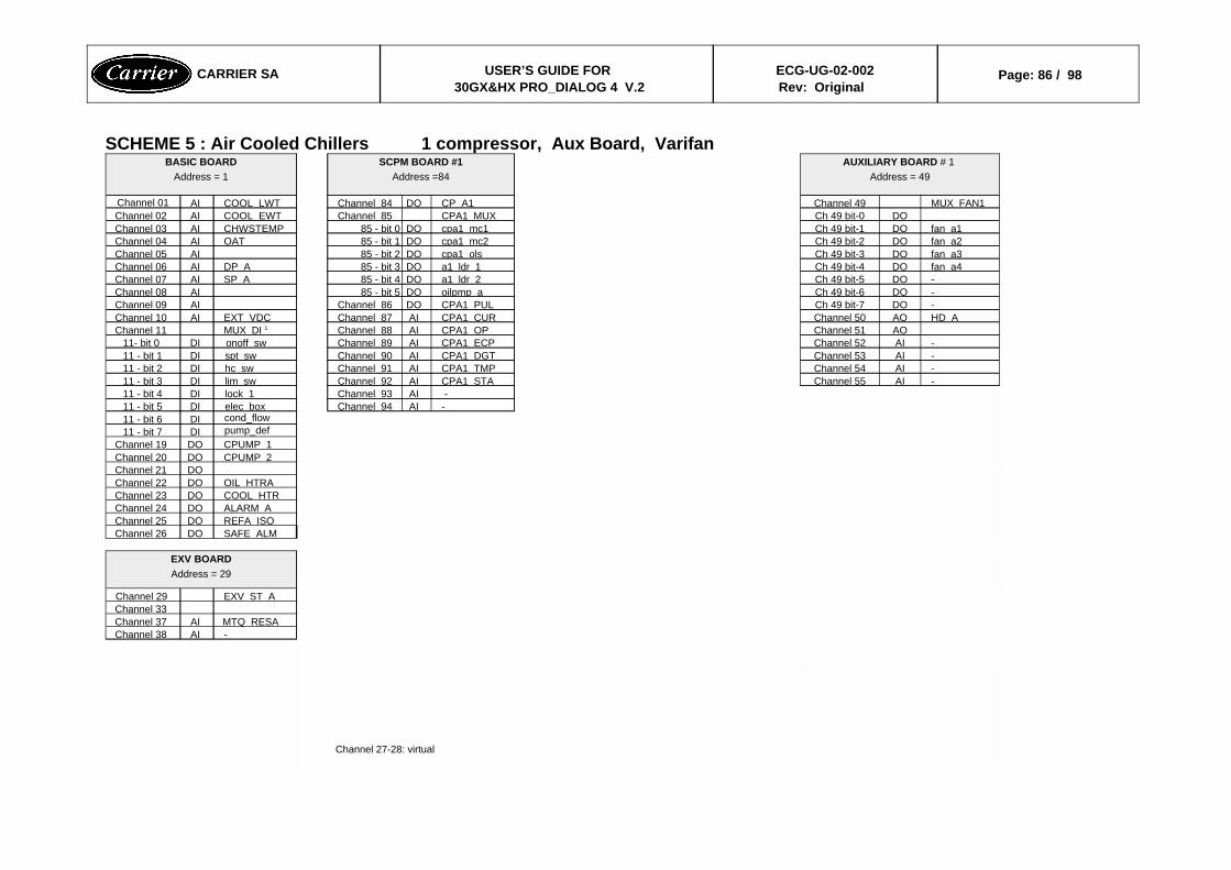
SCHEME 5 : Air Cooled Chillers 1 compressor, Aux Board, Varifan
Channel 27-28: virtual
-AIChannel 38MTQ RESAAIChannel 37
Channel 33EXV ST AChannel 29
EXV BOARDAddress = 29
SAFE ALMDOChannel 26REFA ISODOChannel 25ALARM ADOChannel 24COOL HTRDOChannel 23OIL HTRADOChannel 22
DOChannel 21CPUMP 2DOChannel 20CPUMP 1DOChannel 19pump_defDI11 - bit 7cond_flowDI11 - bit 6
-AIChannel 94elec boxDI11 - bit 5 -AIChannel 93lock 1DI11 - bit 4
-AIChannel 55CPA1 STAAIChannel 92lim swDI11 - bit 3-AIChannel 54CPA1 TMPAIChannel 91hc swDI11 - bit 2-AIChannel 53CPA1 DGTAIChannel 90spt swDI11 - bit 1-AIChannel 52CPA1 ECPAIChannel 89onoff swDI11- bit 0
AOChannel 51CPA1 OPAIChannel 88MUX DI 1Channel 11HD AAOChannel 50CPA1 CURAIChannel 87EXT VDCAIChannel 10-DOCh 49 bit-7CPA1 PULDOChannel 86AIChannel 09-DOCh 49 bit-6oilpmp aDO85 - bit 5AIChannel 08-DOCh 49 bit-5a1 ldr 2DO85 - bit 4SP AAIChannel 07fan a4DOCh 49 bit-4a1 ldr 1DO85 - bit 3DP AAIChannel 06fan a3DOCh 49 bit-3cpa1 olsDO85 - bit 2AIChannel 05fan a2DOCh 49 bit-2cpa1 mc2DO85 - bit 1OATAIChannel 04fan a1DOCh 49 bit-1cpa1 mc1DO85 - bit 0CHWSTEMPAIChannel 03
DOCh 49 bit-0CPA1 MUXChannel 85COOL EWTAIChannel 02MUX FAN1Channel 49CP A1DOChannel 84COOL LWTAIChannel 01
AUXILIARY BOARD # 1 Address = 49
SCPM BOARD #1Address =84
BASIC BOARDAddress = 1
CARRIER SA USER’S GUIDE FOR 30GX&HX PRO_DIALOG 4 V.2
ECG-UG-02-002Rev: Original
Page: 86 / 98
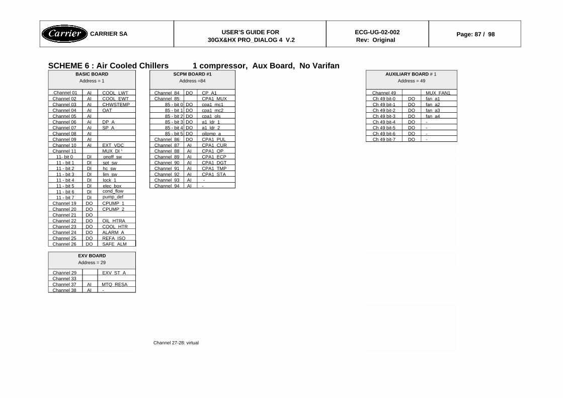
SCHEME 6 : Air Cooled Chillers 1 compressor, Aux Board, No Varifan
Channel 27-28: virtual
-AIChannel 38MTQ RESAAIChannel 37
Channel 33EXV ST AChannel 29
EXV BOARDAddress = 29
SAFE ALMDOChannel 26REFA ISODOChannel 25ALARM ADOChannel 24COOL HTRDOChannel 23OIL HTRADOChannel 22
DOChannel 21CPUMP 2DOChannel 20CPUMP 1DOChannel 19pump_defDI11 - bit 7cond_flowDI11 - bit 6
-AIChannel 94elec boxDI11 - bit 5 -AIChannel 93lock 1DI11 - bit 4CPA1 STAAIChannel 92lim swDI11 - bit 3CPA1 TMPAIChannel 91hc swDI11 - bit 2CPA1 DGTAIChannel 90spt swDI11 - bit 1CPA1 ECPAIChannel 89onoff swDI11- bit 0CPA1 OPAIChannel 88MUX DI 1Channel 11CPA1 CURAIChannel 87EXT VDCAIChannel 10
-DOCh 49 bit-7CPA1 PULDOChannel 86AIChannel 09-DOCh 49 bit-6oilpmp aDO85 - bit 5AIChannel 08-DOCh 49 bit-5a1 ldr 2DO85 - bit 4SP AAIChannel 07-DOCh 49 bit-4a1 ldr 1DO85 - bit 3DP AAIChannel 06fan a4DOCh 49 bit-3cpa1 olsDO85 - bit 2AIChannel 05fan a3DOCh 49 bit-2cpa1 mc2DO85 - bit 1OATAIChannel 04fan a2DOCh 49 bit-1cpa1 mc1DO85 - bit 0CHWSTEMPAIChannel 03fan a1DOCh 49 bit-0CPA1 MUXChannel 85COOL EWTAIChannel 02MUX FAN1Channel 49CP A1DOChannel 84COOL LWTAIChannel 01
AUXILIARY BOARD # 1 Address = 49
SCPM BOARD #1Address =84
BASIC BOARDAddress = 1
CARRIER SA USER’S GUIDE FOR 30GX&HX PRO_DIALOG 4 V.2
ECG-UG-02-002Rev: Original
Page: 87 / 98
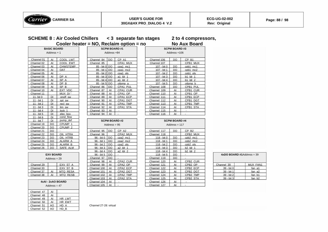
SCHEME 8 : Air Cooled Chillers < 3 separate fan stages 2 to 4 compressors, Cooler heater = NO, Reclaim option = no No Aux Board
HD_BAOChannel 52Channel 27-28: virtual HD AAOChannel 51
HR EWTAIChannel 50HR LWTAIChannel 49
AIChannel 48AIChannel 47
-AIChannel 127-AIChannel 105 -AIChannel 126 -AIChannel 1044xAI - 2xAO BOARD
Address = 47
fan b239 - bit 3CPB2 STAAIChannel 125CPA2 STAAIChannel 103fan b139 - bit 2CPB2 TMPAIChannel 124CPA2 TMPAIChannel 102MTQ RESBAIChannel 38fan a239 - bit 1CPB2 DGTAIChannel 123CPA2 DGTAIChannel 101MTQ RESAAIChannel 37fan a139 - bit 0CPB2 ECPAIChannel 122CPA2 ECPAIChannel 100EXV ST BChannel 33
MUX FAN1Channel 39CPB2 OPAIChannel 121CPA2 OPAIChannel 99EXV ST AChannel 29CPB2 CURAIChannel 120CPA2 CURAIChannel 98-DOChannel 119-DOChannel 97
4xDO BOARD #1Address = 39-DO118 - bit 5-DO96 - bit 5EXV BOARDAddress = 29
b2 ldr 2DO118 - bit 4a2 ldr 2DO96 - bit 4b2 ldr 1DO118 - bit 3a2 ldr 1DO96 - bit 3SAFE ALMDOChannel 26cpb2 olsDO118 - bit 2cpa2 olsDO96 - bit 2ALARM BDOChannel 25cpb2 mc2DO118 - bit 1cpa2 mc2DO96 - bit 1ALARM ADOChannel 24cpb2 mc1DO118 - bit 0cpa2 mc1DO96 - bit 0OIL HTRBDOChannel 23CPB2 MUXChannel 118CPA2 MUXChannel 96OIL HTRADOChannel 22CP B2DOChannel 117CP A2DOChannel 95-DOChannel 21
CPUMP 2DOChannel 20CPUMP 1DOChannel 19
SCPM BOARD #4Address = 117
SCPM BOARD #2Address = 95
pump_defDI11 - bit 7cond_flowDI11 - bit 6
-AIChannel 116-AIChannel 94elec boxDI11 - bit 5 -AIChannel 115 -AIChannel 93lock 1DI11 - bit 4CPB1 STAAIChannel 114CPA1 STAAIChannel 92lim swDI11 - bit 3CPB1 TMPAIChannel 113CPA1 TMPAIChannel 91recl swDI11 - bit 2CPB1 DGTAIChannel 112CPA1 DGTAIChannel 90spt swDI11 - bit 1CPB1 ECPAIChannel 111CPA1 ECPAIChannel 89onoff swDI11- bit 0CPB1 OPAIChannel 110CPA1 OPAIChannel 88MUX DI 1Channel 11CPB1 CURAIChannel 109CPA1 CURAIChannel 87EXT VDCAIChannel 10CPB1 PULDOChannel 108CPA1 PULDOChannel 86SP BAIChannel 09oilpmp bDO107 - bit 5oilpmp aDO85 - bit 5DP BAIChannel 08b1 ldr 2DO107 - bit 4a1 ldr 2DO85 - bit 4SP AAIChannel 07b1 ldr 1DO107 - bit 3a1 ldr 1DO85 - bit 3DP AAIChannel 06cpb1 olsDO107 - bit 2cpa1 olsDO85 - bit 2-AIChannel 05cpb1 mc2DO107 - bit 1cpa1 mc2DO85 - bit 1OATAIChannel 04cpb1 mc1DO107 - bit 0cpa1 mc1DO85 - bit 0CHWSTEMPAIChannel 03CPB1 MUXChannel 107CPA1 MUXChannel 85COOL EWTAIChannel 02CP B1DOChannel 106CP A1DOChannel 84COOL LWTAIChannel 01
SCPM BOARD #3Address =106
SCPM BOARD #1Address =84
BASIC BOARDAddress = 1
CARRIER SA USER’S GUIDE FOR 30GX&HX PRO_DIALOG 4 V.2
ECG-UG-02-002Rev: Original
Page: 88 / 98
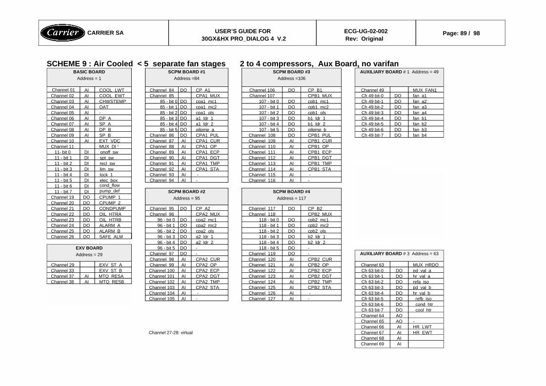
SCHEME 9 : Air Cooled < 5 separate fan stages 2 to 4 compressors, Aux Board, no varifan
AIChannel 69AIChannel 68
HR EWTAIChannel 67Channel 27-28: virtual HR LWTAIChannel 66-AOChannel 65
AOChannel 64cool htrDOCh 63 bit-7cond htrDOCh 63 bit-6refb isoDOCh 63 bit-5-AIChannel 127-AIChannel 105
hr val bDOCh 63 bit-4 -AIChannel 126 -AIChannel 104pd val bDOCh 63 bit-3CPB2 STAAIChannel 125CPA2 STAAIChannel 103refa isoDOCh 63 bit-2CPB2 TMPAIChannel 124CPA2 TMPAIChannel 102MTQ RESBAIChannel 38hr val aDOCh 63 bit-1CPB2 DGTAIChannel 123CPA2 DGTAIChannel 101MTQ RESAAIChannel 37pd val aDOCh 63 bit-0CPB2 ECPAIChannel 122CPA2 ECPAIChannel 100EXV ST BChannel 33MUX HRDOChannel 63CPB2 OPAIChannel 121CPA2 OPAIChannel 99EXV ST AChannel 29
CPB2 CURAIChannel 120CPA2 CURAIChannel 98AUXILIARY BOARD # 3 Address = 63-DOChannel 119-DOChannel 97
-DO118 - bit 5-DO96 - bit 5EXV BOARDAddress = 29
b2 ldr 2DO118 - bit 4a2 ldr 2DO96 - bit 4b2 ldr 1DO118 - bit 3a2 ldr 1DO96 - bit 3SAFE ALMDOChannel 26cpb2 olsDO118 - bit 2cpa2 olsDO96 - bit 2ALARM BDOChannel 25cpb2 mc2DO118 - bit 1cpa2 mc2DO96 - bit 1ALARM ADOChannel 24cpb2 mc1DO118 - bit 0cpa2 mc1DO96 - bit 0OIL HTRBDOChannel 23CPB2 MUXChannel 118CPA2 MUXChannel 96OIL HTRADOChannel 22CP B2DOChannel 117CP A2DOChannel 95CONDPUMPDOChannel 21
CPUMP 2DOChannel 20CPUMP 1DOChannel 19
SCPM BOARD #4Address = 117
SCPM BOARD #2Address = 95
pump_defDI11 - bit 7cond_flowDI11 - bit 6
-AIChannel 116-AIChannel 94elec boxDI11 - bit 5 -AIChannel 115 -AIChannel 93lock 1DI11 - bit 4CPB1 STAAIChannel 114CPA1 STAAIChannel 92lim swDI11 - bit 3CPB1 TMPAIChannel 113CPA1 TMPAIChannel 91recl swDI11 - bit 2CPB1 DGTAIChannel 112CPA1 DGTAIChannel 90spt swDI11 - bit 1CPB1 ECPAIChannel 111CPA1 ECPAIChannel 89onoff swDI11- bit 0CPB1 OPAIChannel 110CPA1 OPAIChannel 88MUX DI 1Channel 11CPB1 CURAIChannel 109CPA1 CURAIChannel 87EXT VDCAIChannel 10
fan b4DOCh 49 bit-7CPB1 PULDOChannel 108CPA1 PULDOChannel 86SP BAIChannel 09fan b3DOCh 49 bit-6oilpmp bDO107 - bit 5oilpmp aDO85 - bit 5DP BAIChannel 08fan b2DOCh 49 bit-5b1 ldr 2DO107 - bit 4a1 ldr 2DO85 - bit 4SP AAIChannel 07fan b1DOCh 49 bit-4b1 ldr 1DO107 - bit 3a1 ldr 1DO85 - bit 3DP AAIChannel 06fan a4DOCh 49 bit-3cpb1 olsDO107 - bit 2cpa1 olsDO85 - bit 2-AIChannel 05fan a3DOCh 49 bit-2cpb1 mc2DO107 - bit 1cpa1 mc2DO85 - bit 1OATAIChannel 04fan a2DOCh 49 bit-1cpb1 mc1DO107 - bit 0cpa1 mc1DO85 - bit 0CHWSTEMPAIChannel 03fan a1DOCh 49 bit-0CPB1 MUXChannel 107CPA1 MUXChannel 85COOL EWTAIChannel 02MUX FAN1Channel 49CP B1DOChannel 106CP A1DOChannel 84COOL LWTAIChannel 01
AUXILIARY BOARD # 1 Address = 49SCPM BOARD #3Address =106
SCPM BOARD #1Address =84
BASIC BOARDAddress = 1
CARRIER SA USER’S GUIDE FOR 30GX&HX PRO_DIALOG 4 V.2
ECG-UG-02-002Rev: Original
Page: 89 / 98

SCHEME 10 : Air Cooled > 4 separate fan stages 2 to 4 compressors, Aux Board, no varifan
AIChannel 69AIChannel 68
HR EWTAIChannel 67Channel 27-28: virtual HR LWTAIChannel 66-AOChannel 65
AOChannel 64cool htrDOCh 63 bit-7cond htrDOCh 63 bit-6refb isoDOCh 63 bit-5-AIChannel 127-AIChannel 105
hr val bDOCh 63 bit-4 -AIChannel 126 -AIChannel 104pd val bDOCh 63 bit-3CPB2 STAAIChannel 125CPA2 STAAIChannel 103refa isoDOCh 63 bit-2CPB2 TMPAIChannel 124CPA2 TMPAIChannel 102-AIChannel 38hr val aDOCh 63 bit-1CPB2 DGTAIChannel 123CPA2 DGTAIChannel 101-AIChannel 37pd val aDOCh 63 bit-0CPB2 ECPAIChannel 122CPA2 ECPAIChannel 100EXV ST BChannel 33MUX HRDOChannel 63CPB2 OPAIChannel 121CPA2 OPAIChannel 99EXV ST AChannel 29
CPB2 CURAIChannel 120CPA2 CURAIChannel 98AUXILIARY BOARD # 3 Address = 63-DOChannel 119-DOChannel 97
-DO118 - bit 5-DO96 - bit 5EXV BOARDAddress = 29
b2 ldr 2DO118 - bit 4a2 ldr 2DO96 - bit 4b2 ldr 1DO118 - bit 3a2 ldr 1DO96 - bit 3SAFE ALMDOChannel 26cpb2 olsDO118 - bit 2cpa2 olsDO96 - bit 2ALARM BDOChannel 25cpb2 mc2DO118 - bit 1cpa2 mc2DO96 - bit 1ALARM ADOChannel 24cpb2_mc1DO118 - bit 0cpa2_mc1DO96 - bit 0OIL_HTRBDOChannel 23
fan b8DOCh 56 bit-7CPB2 MUXChannel 118CPA2 MUXChannel 96OIL HTRADOChannel 22fan b7DOCh 56 bit-6CP B2DOChannel 117CP A2DOChannel 95CONDPUMPDOChannel 21fan b6DOCh 56 bit-5CPUMP 2DOChannel 20fan b5DOCh 56 bit-4CPUMP 1DOChannel 19fan b4DOCh 56 bit-3SCPM BOARD #4
Address = 117SCPM BOARD #2
Address = 95pump_defDI11 - bit 7
fan b3DOCh 56 bit-2cond_flowDI11 - bit 6fan b2DOCh 56 bit-1-AIChannel 116-AIChannel 94elec boxDI11 - bit 5fan b1DOCh 56 bit-0 -AIChannel 115 -AIChannel 93lock 1DI11 - bit 4MUX FAN2Channel 56CPB1 STAAIChannel 114CPA1 STAAIChannel 92lim swDI11 - bit 3
AUXILIARY BOARD # 2 Address = 56CPB1_TMPAIChannel 113CPA1_TMPAIChannel 91recl_swDI11 - bit 2CPB1 DGTAIChannel 112CPA1 DGTAIChannel 90spt swDI11 - bit 1CPB1 ECPAIChannel 111CPA1 ECPAIChannel 89onoff swDI11- bit 0CPB1 OPAIChannel 110CPA1 OPAIChannel 88MUX DI 1Channel 11CPB1 CURAIChannel 109CPA1 CURAIChannel 87EXT VDCAIChannel 10
fan a8DOCh 49 bit-7CPB1 PULDOChannel 108CPA1 PULDOChannel 86SP BAIChannel 09fan a7DOCh 49 bit-6oilpmp bDO107 - bit 5oilpmp aDO85 - bit 5DP BAIChannel 08fan a6DOCh 49 bit-5b1 ldr 2DO107 - bit 4a1 ldr 2DO85 - bit 4SP AAIChannel 07fan a5DOCh 49 bit-4b1 ldr 1DO107 - bit 3a1 ldr 1DO85 - bit 3DP AAIChannel 06fan a4DOCh 49 bit-3cpb1 olsDO107 - bit 2cpa1 olsDO85 - bit 2-AIChannel 05fan a3DOCh 49 bit-2cpb1 mc2DO107 - bit 1cpa1 mc2DO85 - bit 1OATAIChannel 04fan a2DOCh 49 bit-1cpb1 mc1DO107 - bit 0cpa1 mc1DO85 - bit 0CHWSTEMPAIChannel 03fan a1DOCh 49 bit-0CPB1 MUXChannel 107CPA1 MUXChannel 85COOL EWTAIChannel 02MUX FAN1Channel 49CP B1DOChannel 106CP A1DOChannel 84COOL LWTAIChannel 01
AUXILIARY BOARD # 1 Address = 49SCPM BOARD #3Address =106
SCPM BOARD #1Address =84
BASIC BOARDAddress = 1
CARRIER SA USER’S GUIDE FOR 30GX&HX PRO_DIALOG 4 V.2
ECG-UG-02-002Rev: Original
Page: 90 / 98
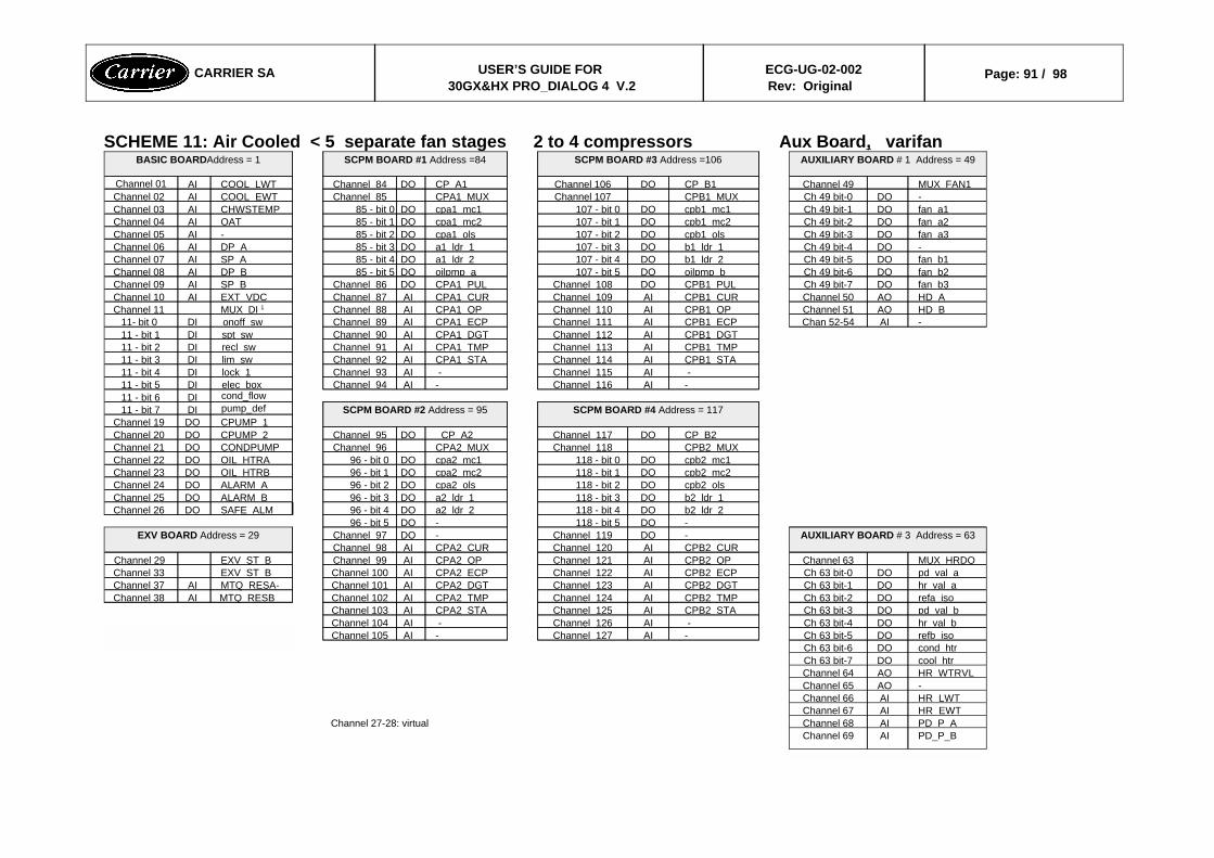
SCHEME 11: Air Cooled < 5 separate fan stages 2 to 4 compressors Aux Board, varifan
PD_P_BAIChannel 69PD P AAIChannel 68Channel 27-28: virtual HR EWTAIChannel 67HR LWTAIChannel 66-AOChannel 65HR WTRVLAOChannel 64 cool htrDOCh 63 bit-7 cond htrDOCh 63 bit-6refb isoDOCh 63 bit-5-AIChannel 127-AIChannel 105hr val bDOCh 63 bit-4 -AIChannel 126 -AIChannel 104pd val bDOCh 63 bit-3CPB2 STAAIChannel 125CPA2 STAAIChannel 103refa isoDOCh 63 bit-2CPB2 TMPAIChannel 124CPA2 TMPAIChannel 102MTQ RESBAIChannel 38hr val aDOCh 63 bit-1CPB2 DGTAIChannel 123CPA2 DGTAIChannel 101MTQ RESA-AIChannel 37pd val aDOCh 63 bit-0CPB2 ECPAIChannel 122CPA2 ECPAIChannel 100EXV ST B Channel 33MUX HRDOChannel 63CPB2 OPAIChannel 121CPA2 OPAIChannel 99EXV ST B Channel 29
CPB2 CURAIChannel 120CPA2 CURAIChannel 98AUXILIARY BOARD # 3 Address = 63-DOChannel 119-DOChannel 97EXV BOARD Address = 29
-DO118 - bit 5-DO96 - bit 5b2 ldr 2DO118 - bit 4a2 ldr 2DO96 - bit 4SAFE ALMDOChannel 26b2 ldr 1DO118 - bit 3a2 ldr 1DO96 - bit 3ALARM BDOChannel 25cpb2 olsDO118 - bit 2cpa2 olsDO96 - bit 2ALARM ADOChannel 24cpb2 mc2DO118 - bit 1cpa2 mc2DO96 - bit 1OIL HTRBDOChannel 23cpb2 mc1DO118 - bit 0cpa2 mc1DO96 - bit 0OIL HTRADOChannel 22CPB2 MUXChannel 118CPA2 MUXChannel 96CONDPUMPDOChannel 21CP B2DOChannel 117CP A2DOChannel 95CPUMP 2DOChannel 20
CPUMP 1DOChannel 19SCPM BOARD #4 Address = 117SCPM BOARD #2 Address = 95pump_defDI11 - bit 7
cond_flowDI11 - bit 6-AIChannel 116-AIChannel 94elec boxDI11 - bit 5 -AIChannel 115 -AIChannel 93lock 1DI11 - bit 4CPB1 STAAIChannel 114CPA1 STAAIChannel 92lim swDI11 - bit 3CPB1 TMPAIChannel 113CPA1 TMPAIChannel 91recl swDI11 - bit 2CPB1 DGTAIChannel 112CPA1 DGTAIChannel 90spt swDI11 - bit 1
-AIChan 52-54CPB1 ECPAIChannel 111CPA1 ECPAIChannel 89onoff swDI11- bit 0HD BAOChannel 51CPB1 OPAIChannel 110CPA1 OPAIChannel 88MUX DI 1Channel 11HD AAOChannel 50CPB1 CURAIChannel 109CPA1 CURAIChannel 87EXT VDCAIChannel 10fan b3DOCh 49 bit-7CPB1 PULDOChannel 108CPA1 PULDOChannel 86SP BAIChannel 09fan b2DOCh 49 bit-6oilpmp bDO107 - bit 5oilpmp aDO85 - bit 5DP BAIChannel 08fan b1DOCh 49 bit-5b1 ldr 2DO107 - bit 4a1 ldr 2DO85 - bit 4SP AAIChannel 07-DOCh 49 bit-4b1 ldr 1DO107 - bit 3a1 ldr 1DO85 - bit 3DP AAIChannel 06fan a3DOCh 49 bit-3cpb1 olsDO107 - bit 2cpa1 olsDO85 - bit 2-AIChannel 05fan a2DOCh 49 bit-2cpb1 mc2DO107 - bit 1cpa1 mc2DO85 - bit 1OATAIChannel 04fan a1DOCh 49 bit-1cpb1 mc1DO107 - bit 0cpa1 mc1DO85 - bit 0CHWSTEMPAIChannel 03-DOCh 49 bit-0CPB1 MUXChannel 107CPA1 MUXChannel 85COOL EWTAIChannel 02MUX FAN1Channel 49CP B1DOChannel 106CP A1DOChannel 84COOL LWTAIChannel 01
AUXILIARY BOARD # 1 Address = 49SCPM BOARD #3 Address =106SCPM BOARD #1 Address =84BASIC BOARDAddress = 1
CARRIER SA USER’S GUIDE FOR 30GX&HX PRO_DIALOG 4 V.2
ECG-UG-02-002Rev: Original
Page: 91 / 98

SCHEME 12 : Air Cooled > 4 separate fan stages 2 to 4 Compressors Aux Board, varifan
PD_P_BAIChannel 69PD P AAIChannel 68Channel 27-28: virtual HR EWTAIChannel 67HR LWTAIChannel 66-AOChannel 65HR WTRVLAOChannel 64 cool htrDOCh 63 bit-7 cond htrDOCh 63 bit-6refb isoDOCh 63 bit-5-AIChannel 127-AIChannel 105hr val bDOCh 63 bit-4 -AIChannel 126 -AIChannel 104pd val bDOCh 63 bit-3CPB2 STAAIChannel 125CPA2 STAAIChannel 103refa isoDOCh 63 bit-2CPB2 TMPAIChannel 124CPA2 TMPAIChannel 102MTQ RESBAIChannel 38hr val aDOCh 63 bit-1CPB2 DGTAIChannel 123CPA2 DGTAIChannel 101MTQ RESAAIChannel 37pd val aDOCh 63 bit-0CPB2 ECPAIChannel 122CPA2 ECPAIChannel 100EXV ST B Channel 33MUX HRDOChannel 63CPB2 OPAIChannel 121CPA2 OPAIChannel 99EXV ST B Channel 29
CPB2 CURAIChannel 120CPA2 CURAIChannel 98AUXILIARY BOARD # 3 Address = 63-DOChannel 119-DOChannel 97EXV BOARD#1 Address = 29
-DO118 - bit 5-DO96 - bit 5-AIChan 59-62b2 ldr 2DO118 - bit 4a2 ldr 2DO96 - bit 4SAFE ALMDOChannel 26
AOChannel 58b2 ldr 1DO118 - bit 3a2 ldr 1DO96 - bit 3ALARM BDOChannel 25HD BAOChannel 57cpb2 olsDO118 - bit 2cpa2 olsDO96 - bit 2ALARM ADOChannel 24fan b7DOCh 56 bit-7cpb2 mc2DO118 - bit 1cpa2 mc2DO96 - bit 1OIL HTRBDOChannel 23fan b6DOCh 56 bit-6cpb2 mc1DO118 - bit 0cpa2 mc1DO96 - bit 0OIL HTRADOChannel 22fan b5DOCh 56 bit-5CPB2 MUXChannel 118CPA2 MUXChannel 96CONDPUMPDOChannel 21fan b4DOCh 56 bit-4CP B2DOChannel 117CP A2DOChannel 95CPUMP 2DOChannel 20fan b3DOCh 56 bit-3CPUMP 1DOChannel 19fan b2DOCh 56 bit-2SCPM BOARD #4 Address = 117SCPM BOARD #2 Address = 95pump_defDI11 - bit 7fan b1DOCh 56 bit-1cond_flowDI11 - bit 6-DOCh 56 bit-0-AIChannel 116-AIChannel 94elec boxDI11 - bit 5MUX FAN1Channel 56 -AIChannel 115 -AIChannel 93lock 1DI11 - bit 4
CPB1 STAAIChannel 114CPA1 STAAIChannel 92lim swDI11 - bit 3AUXILIARY BOARD # 2 Address = 56CPB1 TMPAIChannel 113CPA1 TMPAIChannel 91recl swDI11 - bit 2
CPB1 DGTAIChannel 112CPA1 DGTAIChannel 90spt swDI11 - bit 1-AIChan 52-54CPB1 ECPAIChannel 111CPA1 ECPAIChannel 89onoff swDI11- bit 0
AOChannel 51CPB1 OPAIChannel 110CPA1 OPAIChannel 88MUX DI 1Channel 11HD AAOChannel 50CPB1 CURAIChannel 109CPA1 CURAIChannel 87EXT VDCAIChannel 10fan a7DOCh 49 bit-7CPB1 PULDOChannel 108CPA1 PULDOChannel 86SP BAIChannel 09fan a6DOCh 49 bit-6oilpmp bDO107 - bit 5oilpmp aDO85 - bit 5DP BAIChannel 08fan a5DOCh 49 bit-5b1 ldr 2DO107 - bit 4a1 ldr 2DO85 - bit 4SP AAIChannel 07fan a4DOCh 49 bit-4b1 ldr 1DO107 - bit 3a1 ldr 1DO85 - bit 3DP AAIChannel 06fan a3DOCh 49 bit-3cpb1 olsDO107 - bit 2cpa1 olsDO85 - bit 2-AIChannel 05fan a2DOCh 49 bit-2cpb1 mc2DO107 - bit 1cpa1 mc2DO85 - bit 1OATAIChannel 04fan a1DOCh 49 bit-1cpb1 mc1DO107 - bit 0cpa1 mc1DO85 - bit 0CHWSTEMPAIChannel 03f-DOCh 49 bit-0CPB1 MUXChannel 107CPA1 MUXChannel 85COOL EWTAIChannel 02MUX FAN1Channel 49CP B1DOChannel 106CP A1DOChannel 84COOL LWTAIChannel 01
AUXILIARY BOARD # 1 Address = 49SCPM BOARD #3 Address =106SCPM BOARD #1 Address =84BASIC BOARDAddress = 1
CARRIER SA USER’S GUIDE FOR 30GX&HX PRO_DIALOG 4 V.2
ECG-UG-02-002Rev: Original
Page: 92 / 98

SCHEME 13 : Air Cooled Chillers >2 separate fan stages, 2 to 4 Compressors, Cooler heater = NO, Reclaim option = no, No Aux Board
fan b443 - bit 3Channel 80 - 83 : freeHD BAOChannel 52fan b343 - bit 2Channel 27-28: virtual HD AAOChannel 51fan b243 - bit 1Channel 26 : DO unusedHR EWTAIChannel 50fan b143 - bit 0HR LWTAIChannel 49
MUX FAN2Channel 43AIChannel 48AIChannel 47
4xDO BOARD #2Address = 43
-AIChannel 127-AIChannel 105 -AIChannel 126 -AIChannel 1044xAI - 2xAO BOARD
Address = 47
fan a439 - bit 3CPB2 STAAIChannel 125CPA2 STAAIChannel 103fan a339 - bit 2CPB2 TMPAIChannel 124CPA2 TMPAIChannel 102MTQ RESBAIChannel 38fan a239 - bit 1CPB2 DGTAIChannel 123CPA2 DGTAIChannel 101MTQ RESAAIChannel 37fan a139 - bit 0CPB2 ECPAIChannel 122CPA2 ECPAIChannel 100EXV ST BChannel 33
MUX FAN1Channel 39CPB2 OPAIChannel 121CPA2 OPAIChannel 99EXV ST AChannel 29CPB2 CURAIChannel 120CPA2 CURAIChannel 98-DOChannel 119-DOChannel 97
4xDO BOARD #1Address = 39
-DO118 - bit 5-DO96 - bit 5EXV BOARDAddress = 29
b2 ldr 2DO118 - bit 4a2 ldr 2DO96 - bit 4b2 ldr 1DO118 - bit 3a2 ldr 1DO96 - bit 3unusedDOCh 26-28cpb2 olsDO118 - bit 2cpa2 olsDO96 - bit 2ALARM BDOChannel 25cpb2 mc2DO118 - bit 1cpa2 mc2DO96 - bit 1ALARM ADOChannel 24cpb2 mc1DO118 - bit 0cpa2 mc1DO96 - bit 0OIL HTRBDOChannel 23CPB2 MUXChannel 118CPA2 MUXChannel 96OIL HTRADOChannel 22CP B2DOChannel 117CP A2DOChannel 95DOChannel 21
CPUMP 2DOChannel 20CPUMP 1DOChannel 19
SCPM BOARD #4Address = 117
SCPM BOARD #2Address = 95
pump_defDI11 - bit 7cond_flowDI11 - bit 6
-AIChannel 116-AIChannel 94elec boxDI11 - bit 5 -AIChannel 115 -AIChannel 93lock 1DI11 - bit 4CPB1 STAAIChannel 114CPA1 STAAIChannel 92lim swDI11 - bit 3CPB1 TMPAIChannel 113CPA1 TMPAIChannel 91recl swDI11 - bit 2CPB1 DGTAIChannel 112CPA1 DGTAIChannel 90spt swDI11 - bit 1CPB1 ECPAIChannel 111CPA1 ECPAIChannel 89onoff swDI11- bit 0CPB1 OPAIChannel 110CPA1 OPAIChannel 88MUX DI 1Channel 11CPB1 CURAIChannel 109CPA1 CURAIChannel 87EXT VDCAIChannel 10CPB1 PULDOChannel 108CPA1 PULDOChannel 86SP BAIChannel 09oilpmp bDO107 - bit 5oilpmp aDO85 - bit 5DP BAIChannel 08b1 ldr 2DO107 - bit 4a1 ldr 2DO85 - bit 4SP AAIChannel 07b1 ldr 1DO107 - bit 3a1 ldr 1DO85 - bit 3DP AAIChannel 06cpb1 olsDO107 - bit 2cpa1 olsDO85 - bit 2-AIChannel 05cpb1 mc2DO107 - bit 1cpa1 mc2DO85 - bit 1OATAIChannel 04cpb1 mc1DO107 - bit 0cpa1 mc1DO85 - bit 0CHWSTEMPAIChannel 03CPB1 MUXChannel 107CPA1 MUXChannel 85COOL EWTAIChannel 02CP B1DOChannel 106CP A1DOChannel 84COOL LWTAIChannel 01
SCPM BOARD #3Address =106
SCPM BOARD #1Address =84
BASIC BOARDAddress = 1
CARRIER SA USER’S GUIDE FOR 30GX&HX PRO_DIALOG 4 V.2
ECG-UG-02-002Rev: Original
Page: 93 / 98
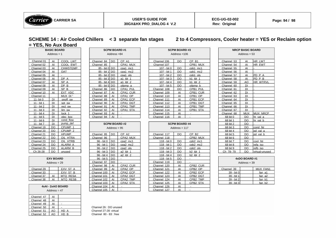
SCHEME 14 : Air Cooled Chillers < 3 separate fan stages 2 to 4 Compressors, Cooler heater = YES or Reclaim option= YES, No Aux Board
Channel 80 - 83 : freeHD BAOChannel 52Channel 27-28: virtual HD AAOChannel 51Channel 26 : DO unused-AIChannel 50
-AIChannel 49AIChannel 48AIChannel 47
-AIChannel 127-AIChannel 105 -AIChannel 126 -AIChannel 1044xAI - 2xAO BOARD
Address = 47
fan b239 - bit 3CPB2 STAAIChannel 125CPA2 STAAIChannel 103fan b139 - bit 2CPB2 TMPAIChannel 124CPA2 TMPAIChannel 102MTQ RESBAIChannel 38fan a239 - bit 1CPB2 DGTAIChannel 123CPA2 DGTAIChannel 101MTQ RESAAIChannel 37fan a139 - bit 0CPB2 ECPAIChannel 122CPA2 ECPAIChannel 100EXV ST BChannel 33
MUX FAN1Channel 39CPB2 OPAIChannel 121CPA2 OPAIChannel 99EXV ST AChannel 29CPB2 CURAIChannel 120CPA2 CURAIChannel 98-DOChannel 119-DOChannel 97
4xDO BOARD #1Address = 39
-DO118 - bit 5-DO96 - bit 5EXV BOARDAddress = 29
b2 ldr 2DO118 - bit 4a2 ldr 2DO96 - bit 4virtual-unusedDOCh 78- 79b2 ldr 1DO118 - bit 3a2 ldr 1DO96 - bit 3unusedDOCh 26-28refb isoDO 68 bit 9cpb2 olsDO118 - bit 2cpa2 olsDO96 - bit 2ALARM BDOChannel 25refa isoDO 68 bit 8cpb2 mc2DO118 - bit 1cpa2 mc2DO96 - bit 1ALARM ADOChannel 24cool htrDO 68 bit 7cpb2 mc1DO118 - bit 0cpa2 mc1DO96 - bit 0OIL HTRBDOChannel 23-DO 68 bit 6CPB2 MUXChannel 118CPA2 MUXChannel 96OIL HTRADOChannel 22pd val bDO 68 bit 5CP B2DOChannel 117CP A2DOChannel 95HPUMPDOChannel 21pd val aDO 68 bit 4CPUMP 2DOChannel 20cond htrDO 68 bit 3CPUMP 1DOChannel 19-DO 68 bit 2SCPM BOARD #4
Address = 117SCPM BOARD #2
Address = 95pump_defDI11 - bit 7
hr val bDO 68 bit 1cond_flowDI11 - bit 6hr val aDO 68 bit 0-AIChannel 116-AIChannel 94elec boxDI11 - bit 5MUX NRCPMUXChannel 68 -AIChannel 115 -AIChannel 93lock 1DI11 - bit 4-DIChannel 67CPB1 STAAIChannel 114CPA1 STAAIChannel 92lim swDI11 - bit 3-DIChannel 66CPB1 TMPAIChannel 113CPA1 TMPAIChannel 91recl swDI11 - bit 2-DIChannel 65CPB1 DGTAIChannel 112CPA1 DGTAIChannel 90spt swDI11 - bit 1-DIChannel 64CPB1 ECPAIChannel 111CPA1 ECPAIChannel 89onoff swDI11- bit 0-DIChannel 63CPB1 OPAIChannel 110CPA1 OPAIChannel 88MUX DI 1Channel 11-DIChannel 62CPB1 CURAIChannel 109CPA1 CURAIChannel 87EXT VDCAIChannel 10-DIChannel 61CPB1 PULDOChannel 108CPA1 PULDOChannel 86SP BAIChannel 09-DIChannel 60oilpmp bDO107 - bit 5oilpmp aDO85 - bit 5DP BAIChannel 08HR WTRVLAOChannel 59b1 ldr 2DO107 - bit 4a1 ldr 2DO85 - bit 4SP AAIChannel 07PD P BAIChannel 58b1 ldr 1DO107 - bit 3a1 ldr 1DO85 - bit 3DP AAIChannel 06PD P AAIChannel 57cpb1 olsDO107 - bit 2cpa1 olsDO85 - bit 2-AIChannel 05-AIChannel 56cpb1 mc2DO107 - bit 1cpa1 mc2DO85 - bit 1OATAIChannel 04-AIChannel 55cpb1 mc1DO107 - bit 0cpa1 mc1DO85 - bit 0CHWSTEMPAIChannel 03HR EWTAIChannel 54CPB1 MUXChannel 107CPA1 MUXChannel 85COOL EWTAIChannel 02HR LWTAIChannel 53CP B1DOChannel 106CP A1DOChannel 84COOL LWTAIChannel 01
NRCP BASIC BOARDAddress = 53
SCPM BOARD #3Address =106
SCPM BOARD #1Address =84
BASIC BOARDAddress = 1
CARRIER SA USER’S GUIDE FOR 30GX&HX PRO_DIALOG 4 V.2
ECG-UG-02-002Rev: Original
Page: 94 / 98
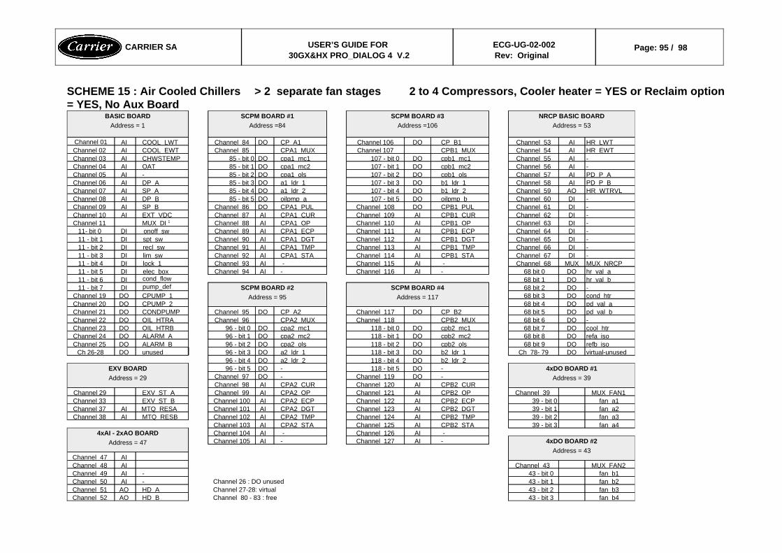
SCHEME 15 : Air Cooled Chillers > 2 separate fan stages 2 to 4 Compressors, Cooler heater = YES or Reclaim option= YES, No Aux Board
fan b443 - bit 3Channel 80 - 83 : freeHD BAOChannel 52fan b343 - bit 2Channel 27-28: virtual HD AAOChannel 51fan b243 - bit 1Channel 26 : DO unused-AIChannel 50fan b143 - bit 0-AIChannel 49
MUX FAN2Channel 43AIChannel 48AIChannel 47
4xDO BOARD #2Address = 43
-AIChannel 127-AIChannel 105 -AIChannel 126 -AIChannel 1044xAI - 2xAO BOARD
Address = 47
fan a439 - bit 3CPB2 STAAIChannel 125CPA2 STAAIChannel 103fan a339 - bit 2CPB2 TMPAIChannel 124CPA2 TMPAIChannel 102MTQ RESBAIChannel 38fan a239 - bit 1CPB2 DGTAIChannel 123CPA2 DGTAIChannel 101MTQ RESAAIChannel 37fan a139 - bit 0CPB2 ECPAIChannel 122CPA2 ECPAIChannel 100EXV ST BChannel 33
MUX FAN1Channel 39CPB2 OPAIChannel 121CPA2 OPAIChannel 99EXV ST AChannel 29CPB2 CURAIChannel 120CPA2 CURAIChannel 98-DOChannel 119-DOChannel 97
4xDO BOARD #1Address = 39
-DO118 - bit 5-DO96 - bit 5EXV BOARDAddress = 29
b2 ldr 2DO118 - bit 4a2 ldr 2DO96 - bit 4virtual-unusedDOCh 78- 79b2 ldr 1DO118 - bit 3a2 ldr 1DO96 - bit 3unusedDOCh 26-28refb isoDO 68 bit 9cpb2 olsDO118 - bit 2cpa2 olsDO96 - bit 2ALARM BDOChannel 25refa isoDO 68 bit 8cpb2 mc2DO118 - bit 1cpa2 mc2DO96 - bit 1ALARM ADOChannel 24cool htrDO 68 bit 7cpb2 mc1DO118 - bit 0cpa2 mc1DO96 - bit 0OIL HTRBDOChannel 23-DO 68 bit 6CPB2 MUXChannel 118CPA2 MUXChannel 96OIL HTRADOChannel 22pd val bDO 68 bit 5CP B2DOChannel 117CP A2DOChannel 95CONDPUMPDOChannel 21pd val aDO 68 bit 4CPUMP 2DOChannel 20cond htrDO 68 bit 3CPUMP 1DOChannel 19-DO 68 bit 2SCPM BOARD #4
Address = 117SCPM BOARD #2
Address = 95pump_defDI11 - bit 7
hr val bDO 68 bit 1cond_flowDI11 - bit 6hr val aDO 68 bit 0-AIChannel 116-AIChannel 94elec boxDI11 - bit 5MUX NRCPMUXChannel 68 -AIChannel 115 -AIChannel 93lock 1DI11 - bit 4-DIChannel 67CPB1 STAAIChannel 114CPA1 STAAIChannel 92lim swDI11 - bit 3-DIChannel 66CPB1 TMPAIChannel 113CPA1 TMPAIChannel 91recl swDI11 - bit 2-DIChannel 65CPB1 DGTAIChannel 112CPA1 DGTAIChannel 90spt swDI11 - bit 1-DIChannel 64CPB1 ECPAIChannel 111CPA1 ECPAIChannel 89onoff swDI11- bit 0-DIChannel 63CPB1 OPAIChannel 110CPA1 OPAIChannel 88MUX DI 1Channel 11-DIChannel 62CPB1 CURAIChannel 109CPA1 CURAIChannel 87EXT VDCAIChannel 10-DIChannel 61CPB1 PULDOChannel 108CPA1 PULDOChannel 86SP BAIChannel 09-DIChannel 60oilpmp bDO107 - bit 5oilpmp aDO85 - bit 5DP BAIChannel 08HR WTRVLAOChannel 59b1 ldr 2DO107 - bit 4a1 ldr 2DO85 - bit 4SP AAIChannel 07PD P BAIChannel 58b1 ldr 1DO107 - bit 3a1 ldr 1DO85 - bit 3DP AAIChannel 06PD P AAIChannel 57cpb1 olsDO107 - bit 2cpa1 olsDO85 - bit 2-AIChannel 05-AIChannel 56cpb1 mc2DO107 - bit 1cpa1 mc2DO85 - bit 1OATAIChannel 04-AIChannel 55cpb1 mc1DO107 - bit 0cpa1 mc1DO85 - bit 0CHWSTEMPAIChannel 03HR EWTAIChannel 54CPB1 MUXChannel 107CPA1 MUXChannel 85COOL EWTAIChannel 02HR LWTAIChannel 53CP B1DOChannel 106CP A1DOChannel 84COOL LWTAIChannel 01
NRCP BASIC BOARDAddress = 53
SCPM BOARD #3Address =106
SCPM BOARD #1Address =84
BASIC BOARDAddress = 1
CARRIER SA USER’S GUIDE FOR 30GX&HX PRO_DIALOG 4 V.2
ECG-UG-02-002Rev: Original
Page: 95 / 98
CARRIER SA USER’S GUIDE FOR 30GX&HX PRO_DIALOG 4 V.2
ECG-UG-02-002Rev: Original
Page: 96 / 98
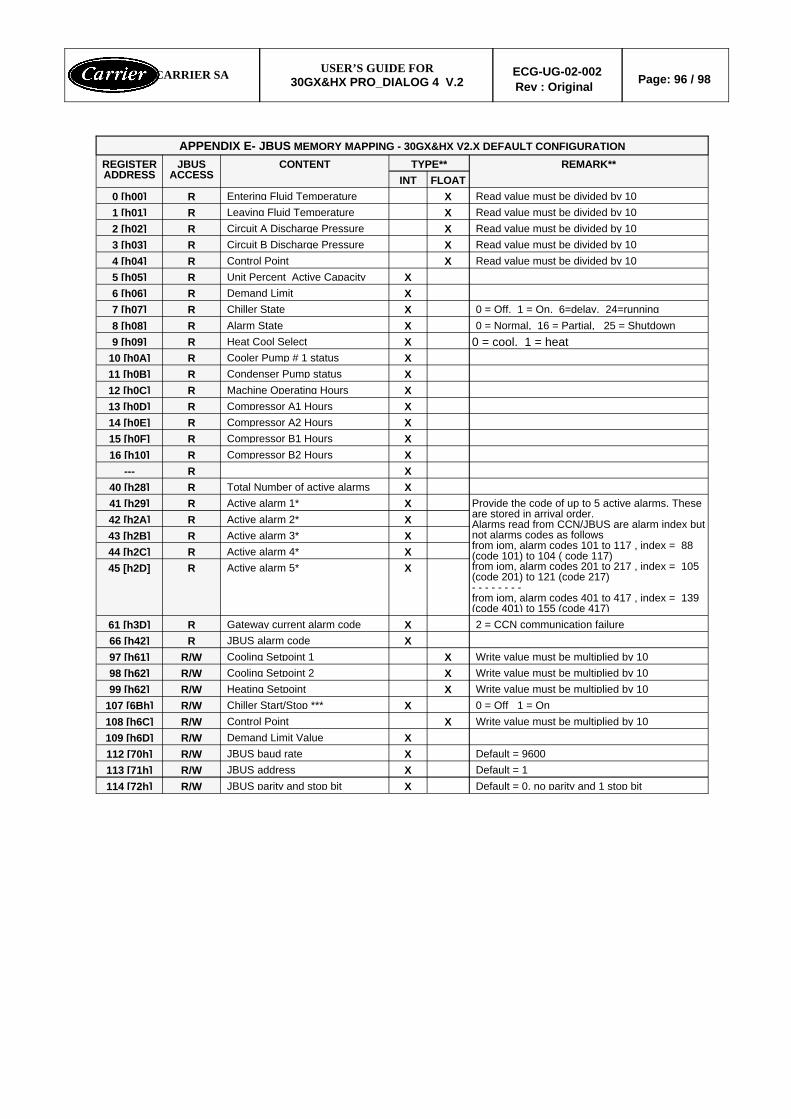
Default = 0, no parity and 1 stop bitXJBUS parity and stop bitR/W114 [72h]Default = 1XJBUS addressR/W113 [71h]Default = 9600XJBUS baud rateR/W112 [70h]
XDemand Limit ValueR/W109 [h6D]Write value must be multiplied by 10XControl PointR/W108 [h6C]0 = Off 1 = OnXChiller Start/Stop ***R/W107 [6Bh]Write value must be multiplied by 10XHeating Setpoint R/W99 [h62]Write value must be multiplied by 10XCooling Setpoint 2R/W98 [h62]Write value must be multiplied by 10XCooling Setpoint 1R/W97 [h61]
XJBUS alarm codeR66 [h42]2 = CCN communication failureXGateway current alarm codeR61 [h3D]
XActive alarm 5*R45 [h2D]XActive alarm 4*R44 [h2C]XActive alarm 3*R43 [h2B]XActive alarm 2*R42 [h2A]
Provide the code of up to 5 active alarms. Theseare stored in arrival order.Alarms read from CCN/JBUS are alarm index butnot alarms codes as followsfrom iom, alarm codes 101 to 117 , index = 88(code 101) to 104 ( code 117)from iom, alarm codes 201 to 217 , index = 105(code 201) to 121 (code 217)- - - - - - - -from iom, alarm codes 401 to 417 , index = 139(code 401) to 155 (code 417)
XActive alarm 1*R41 [h29]XTotal Number of active alarmsR40 [h28]XR---XCompressor B2 HoursR16 [h10]XCompressor B1 HoursR15 [h0F]XCompressor A2 HoursR14 [h0E]XCompressor A1 HoursR13 [h0D]XMachine Operating HoursR12 [h0C]XCondenser Pump statusR11 [h0B]XCooler Pump # 1 statusR10 [h0A]
0 = cool, 1 = heatXHeat Cool SelectR9 [h09]0 = Normal, 16 = Partial, 25 = ShutdownXAlarm StateR8 [h08]0 = Off, 1 = On, 6=delay, 24=runningXChiller StateR7 [h07]
XDemand Limit R6 [h06]XUnit Percent Active CapacityR5 [h05]
Read value must be divided by 10XControl PointR4 [h04]Read value must be divided by 10XCircuit B Discharge PressureR3 [h03]Read value must be divided by 10XCircuit A Discharge PressureR2 [h02]Read value must be divided by 10XLeaving Fluid TemperatureR1 [h01]Read value must be divided by 10XEntering Fluid TemperatureR0 [h00]
FLOATINTREMARK**TYPE**CONTENTJBUS
ACCESSREGISTERADDRESS
APPENDIX E- JBUS MEMORY MAPPING - 30GX&HX V2.X DEFAULT CONFIGURATION
CARRIER SA USER’S GUIDE FOR30GX&HX PRO_DIALOG 4 V.2
ECG-UG-02-002Rev : Original Page: 96 / 98

COMFORTNETWORK
CARRIER SAUSER'S GUIDE FOR
30GX&HX PRO_DIALOG 4 V.2ECG-UG-02-002
Rev: OriginalPage:97 / 98
© CARRIER S.ANOT TO BE DISCLOSED TO PERSONS OUTSIDE CARRIER ORGANIZATION
PRO-DIALOG 30DQ
PRO-DIALOG 30GX & HX
REPEATER
REPEATER
CCN/JBUS
DATAPORT I
DATAPORT II
PRO-DIALOG 30GH
FLOTRONIC II
FLOTRONIC I
FSM
FLOTRONIC I
3200 MP
19XL
AUTODIAL
AUTODIAL
GATEWAY
GATEWAY
MODEM
MODEM
BUILDING
BUILDING
SUPERVISOR
SUPERVISOR
NETWORKSERVICETOOL
PRIMARY CCN BUS
GW
WSM
39 L
CSM
GW
GW
TSM
39 L
39 L
DATA COLLECTION
NDS BRIDGE
DATA TRANSFERT
TSM SECONDARY BUS
SECONDARYBUS
AIR TERMINAL
AIR TERMINAL
35
37
GATEWAYJ-BUS/RS-485 TO
TO
TO
BMS
BMS
BMS
LOCAL BUILDING SUPERVISOR
REMOTE BUILDING SUPERVISOR
SAM
RS-485
ASCII/RS-232
ASCII/RS-232
SERVICE WINDOW 2
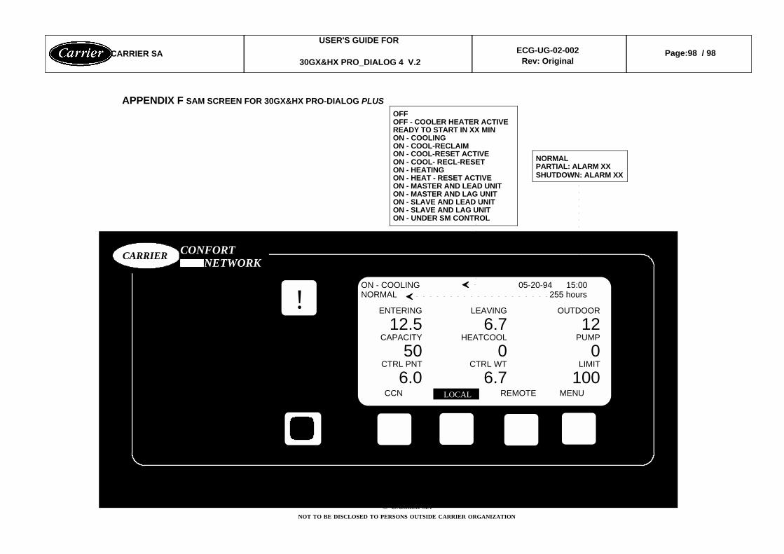
APPENDIX F SAM SCREEN FOR 30GX&HX PRO-DIALOG PLUS
CARRIER SAUSER'S GUIDE FOR
30GX&HX PRO_DIALOG 4 V.2ECG-UG-02-002
Rev: OriginalPage:98 / 98
© CARRIER S.ANOT TO BE DISCLOSED TO PERSONS OUTSIDE CARRIER ORGANIZATION
!ON - COOLING 05-20-94 15:00NORMAL 255 hours
ENTERING LEAVING OUTDOOR
12.5 6.7 12CAPACITY HEATCOOL PUMP
50 0 0CTRL PNT CTRL WT LIMIT
6.0 6.7 100 CCN LOCAL REMOTE MENU LOCAL
CARRIER CONFORTNETWORK
OFFOFF - COOLER HEATER ACTIVEREADY TO START IN XX MINON - COOLINGON - COOL-RECLAIMON - COOL-RESET ACTIVEON - COOL- RECL-RESETON - HEATINGON - HEAT - RESET ACTIVEON - MASTER AND LEAD UNITON - MASTER AND LAG UNITON - SLAVE AND LEAD UNITON - SLAVE AND LAG UNITON - UNDER SM CONTROL
NORMALPARTIAL: ALARM XXSHUTDOWN: ALARM XX