user manual tessera processing - brompton technology
TRANSCRIPT
USER MANUAL TESSERA PROCESSINGTessera Version 3.1

2 TESSERA - V3.1 | USER MANUAL - REV A |

TESSERA - V3.1 | USER MANUAL - REV A | BROMPTON SUPPORT 3
BROMPTON SUPPORTShould you have any problems with your Brompton Technology product please contact our support team using the following details.
EU SupportAvailable between 10:00 and 18:00 EST:
l Tel: +44 (0)20 7471 9444 l Email: [email protected]
Urgent out-of-hours support:
l Tel: +44 (0)20 7471 9441 l Email: [email protected]
US SupportAvailable between 09:00 and 17:00 EDT:
l Tel: +1 (844) 427 6786 l Email: [email protected]

4 TESSERA - V3.1 | USER MANUAL - REV A | MANUAL CHANGELOG
MANUAL CHANGELOG
Manual Tessera V3.1 - Rev AReleased 05/03/2021 with the following changes:
l Updated section: Output Capacity on page 43. l Updated section: Frame Rate Multiplication on page 216. l New section: Frame Remapping on page 217. l Updated section: HFR+ (High Frame Rate) on page 220. l Updated section: Enabling Live Control on page 222 l New section: IP Control on page 230.
Manual Tessera V3.0 - Rev BReleased 22/01/2021 with the following changes:
l General minor updates.
Manual Tessera V3.0 - Rev AReleased 20/09/2020 with the following changes:
l Updated style and look of manual. l Implemented a referenced Manual Changelog. l Updated section: General Overview on page 13. l New data sheet: Tessera S8 LED Processor on page 23. l New section: High Dynamic Range on page 57. l New section: Dynamic Calibration on page 59 l Updated Creating a New Project on Local UI and Tessera Remote on page 63 with details
about "Enable HDR" on page 65. l New section: Enable HDR on page 65. l New section: Device Properties on page 74. l New section: ThermaCal on page 78. l Updated Tessera S8 details for Inputs: 4K Sources (for SX40 and S8) on page 136. l New section: Input Metadata on page 138. l New section: Input Override on page 142. l Updated section: Redundancy Configuration on page 37. l Updated UI images: Global Colour on page 178. l Updated section: Colour Temperature on page 179. l Updated section: Gamma on page 179.
TESSERA - V3.1 | USER MANUAL - REV A | MANUAL CHANGELOG 5
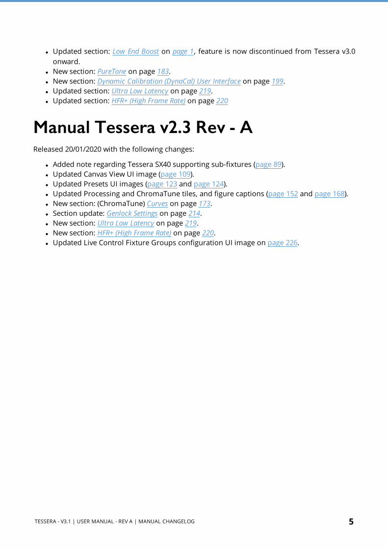
l Updated section: Low End Boost on page 1, feature is now discontinued from Tessera v3.0 onward.
l New section: PureTone on page 183. l New section: Dynamic Calibration (DynaCal) User Interface on page 199. l Updated section: Ultra Low Latency on page 219. l Updated section: HFR+ (High Frame Rate) on page 220
Manual Tessera v2.3 Rev - AReleased 20/01/2020 with the following changes:
l Added note regarding Tessera SX40 supporting sub-fixtures (page 89). l Updated Canvas View UI image (page 109). l Updated Presets UI images (page 123 and page 124). l Updated Processing and ChromaTune tiles, and figure captions (page 152 and page 168). l New section: (ChromaTune) Curves on page 173. l Section update: Genlock Settings on page 214. l New section: Ultra Low Latency on page 219. l New section: HFR+ (High Frame Rate) on page 220. l Updated Live Control Fixture Groups configuration UI image on page 226.

6 TESSERA - V3.1 | USER MANUAL - REV A | MANUAL CHANGELOG
TABLE OF CONTENTBrompton Support 3
Manual Changelog 4
Section 1 - Introduction 11
Section 2 - General Overview 13
2.1 - Tessera LED Processors 13
2.2 - System Overview 16
2.3 - Tessera SX40 LED Processor 19
2.4 - Tessera S8 LED Processor 23
2.5 - Tessera M2 LED Processor 25
2.6 - Tessera S4 LED Processor 27
2.7 - Tessera T1 LED Processor 29
Section 3 - Quickstart 31
3.1 - Tessera LED Processor Setup 31
3.2 - Tessera Project Setup 32
3.3 - Connecting Fixtures 33
Section 4 - System Configuration 35
4.1 - Connecting Fixtures 35
4.2 - Connection Guidelines 35
4.3 - Redundancy Configuration 37
4.4 - Output Capacity 43
4.5 - Combining Processors 46
Section 5 - Tessera Management Software 47
5.1 - Local User Interface 47
5.2 - Tessera Remote and Offline Editor 47
5.3 - Installation for Windows PC 48
5.4 - Installation for Mac OS X 50
5.5 - Network Settings for Remote Management 50

TESSERA - V3.1 | USER MANUAL - REV A | TABLE OF CONTENT 7
5.6 - Connecting to a Tessera LED Processor 51
5.7 - Multiple Processors Control 55
Section 6 - High Dynamic Range 57
6.1 - Supported HDR Formats 57
6.2 - HDR Features 58
6.3 - Dynamic Calibration 59
Section 7 - Project Setup 61
7.1 - Project Management 61
7.2 - Enable HDR 65
7.3 - Canvas Resolutions 65
7.4 - Low Latency Mode 67
7.5 - Mapping Options 68
Section 8 - Fixtures 71
8.1 - Fixture Libraries 71
8.2 - Fixture Properties 71
8.3 - Device Properties 74
8.4 - OSD 76
8.5 - Studio mode 77
8.6 - ThermaCal 78
8.7 - Fixture Context Menu 80
8.8 - Adding Fixtures to a Project 82
8.9 - Add Fixtures from Network 82
8.10 - Add Fixtures from Library 87
8.11 - Assigning or Modifying Online Fixture Topology 87
8.12 - Sub-Fixtures 89
8.13 - Understanding Topology and Association 97
8.14 - Fixture Layout 104
Section 9 - Main Project Screen 109
9.1 - Canvas View 109
9.2 - Presets 123

8 TESSERA - V3.1 | USER MANUAL - REV A | TABLE OF CONTENT
9.3 - Log 127
9.4 - Moving Around the Canvas 128
9.5 - Project Data Export 129
9.6 - Online View 131
9.7 - Topology View 133
Section 10 - Inputs 134
10.1 - Source Selection 134
10.2 - HD Sources (for M2, T1, S4) 135
10.3 - 4K Sources (for SX40 and S8) 136
10.4 - Input Metadata 138
10.5 - Input Override 142
10.6 - Input Colour Control 146
10.7 - Histograms 147
Section 11 - Processing 152
11.1 - Scaling and Cropping 152
11.2 - Scaling and Cropping 157
11.3 - Active Area 164
11.4 - ChromaTune 168
Section 12 - Test Patterns 174
12.1 - Processor Test Patterns 174
12.2 - Custom Test Patterns 175
12.3 - Fixture Test Patterns 176
12.4 - Freeze/Blackout 176
12.5 - Front Panel Button Settings 176
Section 13 - Global Colour 178
13.1 - Brightness 179
13.2 - Colour Temperature 179
13.3 - Gamma 179
13.4 - Dark Magic 181
13.5 - PureTone 183

TESSERA - V3.1 | USER MANUAL - REV A | TABLE OF CONTENT 9
13.6 - Gain Controls 184
13.7 - Studio Mode 185
13.8 - On-Screen Colour Adjustment 186
13.9 - Dynamic Calibration (DynaCal) User Interface 199
Section 14 - Network 212
14.1 - Network Load 212
14.2 - Network Bit Depth 213
14.3 - Additional Video Delay 213
14.4 - Genlock Settings 214
14.5 - Ultra Low Latency 219
14.6 - HFR+ (High Frame Rate) 220
Section 15 - Live Control 221
15.1 - Enabling Live Control 222
15.2 - Parameter Indicators 223
15.3 - Control Profiles 224
15.4 - DMX Control 228
15.5 - EDMX Control 229
15.6 - IP Control 230
15.7 - Tessera Control 231
Section 16 - Processor Settings 233
16.1 - Processor 234
16.2 - General 235
16.3 - Security 238
16.4 - Date and Time 239
16.5 - Fixture Library 240
16.6 - Preferences 245
16.7 - Crash Management 247
16.8 - Restore Factory Settings 248
16.9 - Format Internal Storage 249
16.10 - Reload Firmware 250

10 TESSERA - V3.1 | USER MANUAL - REV A | TABLE OF CONTENT
16.11 - Processor Status 252
16.12 - About 253
Appendix A - Keyboard Shortcuts 254
Global 254
Canvas 255
While Adding Fixtures 255
OSCA 256
Appendix B - Cable Requirements For Tessera SX40 and XD 257
Tessera SX40 and XD Cable Requirements 257
10G Ethernet Compatibility 258
Appendix C - Setting IP Addresses 260
Setting the IP Address on Windows Systems 260
Setting the IP Address on Mac OS X Systems 262
Appendix D - DMX Channel Allocations 264
Appendix E - Warranty 273
Warranty Conditions 273
Glossary 275
TESSERA - V3.1 | USER MANUAL - REV A | SECTION 1 - INTRODUCTION 11
SECTION 1 - INTRODUCTION
Copyright©2012- 2021 Brompton Technology Ltd.. All rights reserved.
TrademarksBrompton is a registered trademark owned by Carallon Ltd.
All other brand and product names used in this document may be trademarks, registered trademarks or trade names of their respective holders.
ChangesThe information and specifications contained within this document are subject to change without notice. Brompton Technology Ltd. reserves the right to make improvements and changes to the hardware and software described in this document at any time and without notice.
Brompton Technology Ltd. assumes no responsibility or liability for any errors or inaccuracies that might occur in this document.
About This ManualThis manual provides all the information required for the correct and safe use of the Tessera LED Processors and the supplied Tessera Software.
This Revision A of the manual was written for Tessera software Version 3.1 and published on the 05 March 2021.
About the Tessera SystemThe Tessera System comprises processors, distribution units, receiver cards and software. These elements can be used with a wide range of LED fixtures.

12 TESSERA - V3.1 | USER MANUAL - REV A | SECTION 1 - INTRODUCTION
Brompton Technology Ltd. partners with both purchasers and manufacturers who wish to use Brompton processing to control their LED video products. For more information about Brompton Technology Ltd. please contact: [email protected].
Handling and Safe OperationThe Tessera LED Processors and distribution units are packaged in a rugged custom-designed 19" rack mounting case with integral mounting handles.
The processor should be adequately supported in a rack at all times. The weight of the processor should never be supported entirely on the rack ears as this can lead to distortion, especially if the rack is roughly handled.
The processors and distribution units should only be opened by professionals as it will expose the user to potentially dangerous voltages. The units must never be operated with the cover removed. Opening the units without an approval from Brompton Technical Support will invalidate the warranty.
The product is designed to operate from a grounded power source between 100 and 250V AC, 47 -63Hz. Ensure the use of a stable power source. If your power source is prone to surges, place the unit on an uninterruptible power supply (UPS) to prevent exposure to voltages that could potentially damage the system.

TESSERA - V3.1 | USER MANUAL - REV A | SECTION 2 - GENERAL OVERVIEW 13
SECTION 2 - GENERAL OVERVIEW
2.1 - Tessera LED ProcessorsBrompton Technology Ltd. makes a variety of Tessera LED video processors for different applications.
2.1.1 - Tessera SX40 LED Processor
Our Tessera SX40 is the highest capacity processor we currently offer. It is capable of supporting a nominal 9 million pixels and 4k canvas resolutions with HDMI 2.0 and 12G SDI inputs. Eight 10 Gigabit ports over 4 trunks that allow data transfer using single mode fibre or CAT6 copper cable. The Tessera SX40 can support up to 2000 connected fixtures and offers maximum flexibility with the use of the Tessera XD Distribution system.
See Tessera SX40 LED Processor on page 19 for more information.
NOTE The Tessera SX40 only support sub-fixtures from Tessera V2.31 onwards.

14 TESSERA - V3.1 | USER MANUAL - REV A | 2.1 - TESSERA LED PROCESSORS
2.1.2 - Tessera S8 LED Processor
The mid-range Tessera S8 LED Processor is perfect for high-profile projects that don’t require large output capacity but would still benefit from the flexibility of Brompton’s industry-leading Tessera feature set and easy-to-use software. It is capable of supporting a nominal 4.5 million pixels (half of the Tessera SX40) and 4k canvas resolutions with HDMI 2.0 and 12G SDI inputs. Eight 1 Gigabit ports that allow data transfer over CAT5e copper cable.
See Tessera S8 LED Processor on page 23 for more information.
2.1.3 - Tessera M2 LED Processor
The Tessera M2 is the most popular processor to drive HD content. It can control a nominal 2 million pixels over four 1 Gigabit outputs to a fixture count of up to 2000. Supports 3G-SDI and DVI-I inputs.
See Tessera M2 LED Processor on page 25 for more information.

TESSERA - V3.1 | USER MANUAL - REV A | 2.1 - TESSERA LED PROCESSORS 15
2.1.4 - Tessera S4 LED Processor
The Tessera S4 processor is ideal for HD resolution screens (2M pixels). The Tessera S4 LED Processor does not have the front-side processing, scaling or degree by degree rotation of the Tessera T1 and the Tessera M2 but can control the same number of pixels across four Gigabit outputs as the Tessera M2.
See Tessera S4 LED Processor on page 27 for more information.
2.1.5 - Tessera T1 LED Processor
The Tessera T1 is ideal for creative shows requiring flexibility over number of fixtures. It has a DVI- D input and supports a capacity of 0.5 million pixels in a HD canvas. The Tessera T1 includes most of the main features available with the Tessera systems, with one output port supporting up to 500 fixtures.
See Tessera T1 LED Processor on page 29 for more information.

16 TESSERA - V3.1 | USER MANUAL - REV A | 2.2 - SYSTEM OVERVIEW
2.2 - System OverviewThe Tessera system can be controlled locally using a monitor, keyboard and mouse connected directly to a Tessera LED Processor. Alternatively, you can use the Tessera Remote software on a Windows PC or Mac connected to the processor via a Gigabit Ethernet network. The Tessera Remote software can be used in Offline Editor mode, to allow preparation of project files without a processor.
The processors have an integral DisplayPort (DP++) output and USB ports for local control and monitoring. Each Tessera output can be distributed using standard Gigabit Ethernet switches or fibre optic transceivers.
TESSERA - V3.1 | USER MANUAL - REV A | 2.2 - SYSTEM OVERVIEW 17
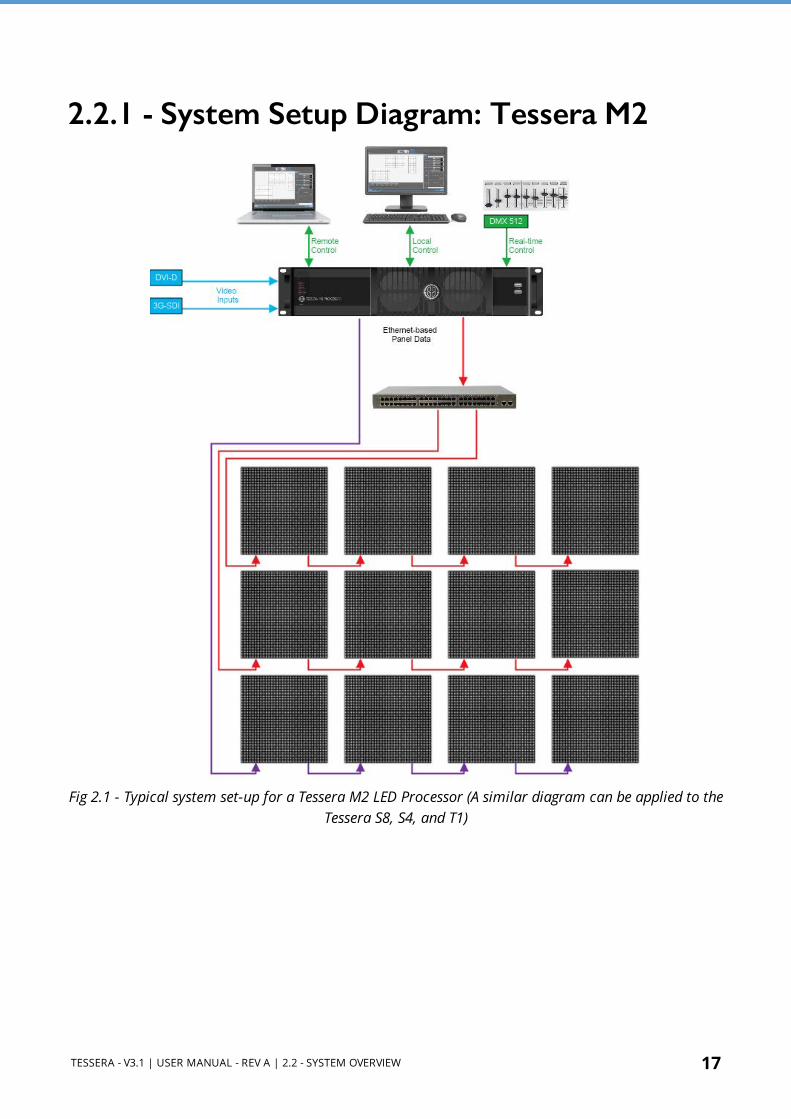
2.2.1 - System Setup Diagram: Tessera M2
Fig 2.1 - Typical system set-up for a Tessera M2 LED Processor (A similar diagram can be applied to the Tessera S8, S4, and T1)

18 TESSERA - V3.1 | USER MANUAL - REV A | 2.2 - SYSTEM OVERVIEW
2.2.2 - System Setup Diagram: Tessera SX40
Fig 2.2 - Typical system set-up for the Tessera SX40 LED Processor

TESSERA - V3.1 | USER MANUAL - REV A | 2.3 - TESSERA SX40 LED PROCESSOR 19
2.3 - Tessera SX40 LED Processor
2.3.1 - Front Panel
Feature Description
Front Panel Status LEDs
Blackout button Sends the output of the processor to black
Freeze button Freezes the output of the processor
Reset buttonPress to reset the processor, press and hold for 10 seconds to restore to factory settings. Warning, this will delete all project files and Fixture Packs not included with the base firmware.
2 x USB 2.0 type A portsTo connect USB memory storage devices and peripherals e.g. keyboard and mouse
2.3.2 - Front Panel Status LEDsLED Name Indication
ActiveOn: Processor in operation
Blinking: Processor booting up
Ethernet The processor is detecting a network connection
Video In The processor is connected to a valid video input source
Tessera Out The processor is connected to fixtures
Reference InThe processor has a valid source of genlock connected to the reference input connector
Overtemp
Off: Processor is in normal operating temperatures
Blinking: Processor overheating but operational
On: Processor overheated and shutdown

20 TESSERA - V3.1 | USER MANUAL - REV A | 2.3 - TESSERA SX40 LED PROCESSOR
2.3.3 - Rear Panel Connections
Feature Description
Management EthernetConnect a PC or Mac running Tessera Remote, Tessera Control applications or an eDMX protocol directly to the local data Gigabit Ethernet port. The two ports work as a switch to daisy-chain units.
Local User InterfaceTessera SX40 LED Processor can be operated locally with a monitor connected via DisplayPort. Peripherals such as mouse and keyboard can be connected to the USB ports on either the front or rear panel.
HDMI InputA HDMI 2.0 input with support for digital 4k progressive signal up to 4096x2160 and frame rates up to 144Hz (maximum pixel clock of 600MHz). See Canvas Resolutions on page 65 for more information.
Reference Input Used for analog bi-level or tri-level sync.
12G-SDI Input
A 12G-SDI input is available. The SDI inputs supports HD-SDI, 3G-SDI level A or level B, 6G-SDI and 12G-SDI, 2SI format; SQ not supported. 12G-SDI accepts a progressive signal of up to 4096 x 2160 resolution at 23.98Hz to 60Hz framerate with 10 bits per channel colour depth.
Loop Thru Ports All video inputs and syncs have re-clocked loop thru ports.
10 Gigabit Ethernet Outputs
The Tessera SX40 LED Processor has four 10 Gigabit outputs which can be used by plugging a Tessera XD Distribution Unit to distribute the signal. Fixtures should be connected to the EtherCON connectors in the Tessera XD Unit with Gigabit Ethernet cable (Cat-5e or above). See System Configuration on page 35 for more information.
DMX512-A Input and Thru
For DMX real-time control.
On/Off SwitchThe processor can be shut down from the local interface or remote computer. No harm will result from turning the processor off at the switch.
IEC Mains Input The input is auto ranging from 100-250v/47-63Hz.

TESSERA - V3.1 | USER MANUAL - REV A | 2.3 - TESSERA SX40 LED PROCESSOR 21
2.3.4 - Tessera XD Distribution Unit
Front Panel
Front Panel TouchscreenA front touchscreen displays some information for confirmation during setup and troubleshooting. This includes:
l All Ethernet port link states l Processor connection state l The name of the current project open in the Tessera SX40 l XD name for easy identification in large projects
The screen orientation and brightness is configurable, and the screen and per-port LEDs may be disabled for stealth operation in dark environments.
Firmware is reloadable from the Tessera SX40, just as with other Tessera fixtures.

22 TESSERA - V3.1 | USER MANUAL - REV A | 2.3 - TESSERA SX40 LED PROCESSOR
Rear Panel Connections
Feature Description
Two 10G Tessera Protocol copper inputs for connection from Tessera SX40
Supports Neutrik EtherCON Cat 6A / etherCON (CAT5e) connectors
Compatible with standard RJ45 connectors
Requires Cat6A cable (up to 60m) or Cat5e cable (up to 30m)
One of the 10G ports can be used as thru connection for daisy-chaining of additional XDs
Two 10G Tessera Protocol fibre inputs for connection from Tessera SX40 (Single mode ONLY)
Supports Neutrik opticalCON DUO / DUO ARMORED / DUO X-TREME / DUO LITE connectors
Compatible with standard LC-Duplex connectors
Requires 1310nm, 9/125um single-mode fibre (up to 2KM) with PC or UPC connectors
One of the 10G ports can be used as thru connection for daisy-chaining of additional XDs
Auto-switching between fibre and copper
Thru port auto-switches independently from input
Up to five XDs may be daisy-chained
Position 1G output ports in multiple locations for cabling convenience
Bandwidth of each 1G port is shared between all daisy-chained XDs
Extend 10G cable lengths using a Tessera XD as a signal repeater
Convert between 10G fibre and 10G copper (or vice versa) using an XD as a media converter
Ten 1G Tessera Protocol outputs for connection to fixtures
Neutrik etherCON connectors, compatible with standard RJ45
Each 1G output supports a nominal 525K pixels at 8bpc, 60Hz
Pixel capacity per 1G port scales according to selected bit depth and framerate

TESSERA - V3.1 | USER MANUAL - REV A | 2.4 - TESSERA S8 LED PROCESSOR 23
2.4 - Tessera S8 LED Processor
2.4.1 - Front Panel
Feature Description
Front Panel Status LEDs
Blackout button Sends the output of the processor to black
Freeze button Freezes the output of the processor
Reset buttonPress to reset the processor, press and hold for 10 seconds to restore to factory settings. Warning, this will delete all project files and Fixture Packs not included with the base firmware.
2 x USB 2.0 type A portsTo connect USB memory storage devices and peripherals e.g. keyboard and mouse
2.4.2 - Front Panel Status LEDsLED Name Indication
ActiveOn: Processor in operation
Blinking: Processor booting up
Ethernet The processor is detecting a network connection
Video In The processor is connected to a valid video input source
Tessera Out The processor is connected to fixtures
Reference InThe processor has a valid source of genlock connected to the reference input connector
Overtemp
Off: Processor is in normal operating temperatures
Blinking: Processor overheating but operational
On: Processor overheated and shutdown

24 TESSERA - V3.1 | USER MANUAL - REV A | 2.4 - TESSERA S8 LED PROCESSOR
2.4.3 - Rear Panel Connections
Feature Description
Management EthernetConnect a PC or Mac running Tessera Remote, Tessera Control applications or an eDMX protocol directly to the local data Gigabit Ethernet port. The two ports work as a switch to daisy-chain units.
Local User InterfaceTessera S8 LED Processor can be operated locally with a monitor connected via DisplayPort. Peripherals such as mouse and keyboard can be connected to the USB ports on either the front or rear panel.
HDMI InputA HDMI 2.0 input with support for digital 4k progressive signal up to 4096x2160 and frame rates up to 144Hz (maximum pixel clock of 600MHz). See Canvas Resolutions on page 65 for more information.
Reference Input Used for analog bi-level or tri-level sync.
12G-SDI Input
A 12G-SDI input is available. The SDI inputs supports HD-SDI, 3G-SDI level A or level B, 6G-SDI and 12G-SDI, 2SI format; SQ not supported. 12G-SDI accepts a progressive signal of up to 4096 x 2160 resolution at 23.98Hz to 60Hz framerate with 10 bits per channel colour depth.
Loop Thru Ports All video inputs and syncs have re-clocked loop thru ports.
1 Gigabit Ethernet Outputs
The Tessera S8 LED Processor has eight 1 Gigabit Ethernet outputs which are provided on EtherCON connectors. Fixtures must be connected using Gigabit Ethernet cable (Cat-5e or above). See System Configuration on page 35 for more information.
DMX512-A Input and Thru
For DMX real-time control.
On/Off SwitchThe processor can be shut down from the local interface or remote computer. No harm will result from turning the processor off at the switch.
IEC Mains Input The input is auto ranging from 100-250v/47-63Hz.

TESSERA - V3.1 | USER MANUAL - REV A | 2.5 - TESSERA M2 LED PROCESSOR 25
2.5 - Tessera M2 LED Processor
2.5.1 - Front Panel
Feature Description
Front panel status LEDs
Reset buttonPress to reset the processor, press and hold for 10 seconds to restore to factory settings. Warning, this will delete all project files and Fixture Packs not included with the base firmware
2 x USB 2.0 type A portsTo connect USB memory storage devices and peripherals e.g. keyboard and mouse
2.5.2 - Front Panel Status LEDsLED Name Indication
ActiveOn: Processor in operation
Blinking: Processor booting up
Ethernet The processor is detecting a network connection
DMX In A DMX Signal is being received by the processor
Video In The processor is connected to a valid video input source
Reference InThe processor has a valid source of genlock connected to the reference input connector
Tessera Out The processor is connected to fixtures
Black/Freeze Either the blackout or freeze button has been enabled
Overtemp
Off: Processor in normal operating temperatures
Blinking: Processor overheating but operational
On: Processor overheated and shutdown

26 TESSERA - V3.1 | USER MANUAL - REV A | 2.5 - TESSERA M2 LED PROCESSOR
2.5.3 - Rear Panel Connections
Feature Description
Management Ethernet Connect a PC or Mac running the Tessera Remote, Tessera Control application or an eDMX protocol directly to the local data Gigabit Ethernet port. The two ports work as a switch to daisy-chain units.
Local User InterfaceThe Tessera M2 LED Processor can be operated locally with a monitor connected via DisplayPort. Peripherals such as mouse and keyboard can be connected to the USB ports on either the front or rear panel.
DVI Input
A DVI input of up to 1920x1080 @ 60Hz (148.5MHz pixel clock) is supported. This is a DVI-I input which supports DVI-D, VGA/ RGBHV and Component Analogue (YPbPr) with a suitable adapter. See Canvas Resolutions on page 65 for more information.
Reference Input Used for analog bi-level or tri-level sync.
3G-SDI Input
Two 3G-SDI inputs are available. Both inputs can be used concurrently as an independent input. The SDI inputs support 3G-SDI level A or level B. Both inputs can be used together to support Dual Link HD-SDI.
3G-SDI accepts progressive and interlaced signal of up to 1920x1080 resolution at 23.98Hz to 60Hz framerate with 10 bits per channel colour depth.
Loop Thru Ports All video inputs and syncs have re-clocked loop thru ports.
Gigabit Ethernet Outputs
The Tessera M2 LED Processor has four 1 Gigabit Ethernet outputs which are provided on EtherCON connectors. Fixtures must be connected using Gigabit Ethernet cable (Cat-5e or above). See System Configuration on page 35 for more information.
DMX 512-A Input For DMX real-time control.
On/Off Switch The processor can be shut down from the local interface or remote computer. No harm will result from turning the processor off at the switch.
IEC Mains Input The input is auto ranging from 100-250v/47-63Hz
TESSERA - V3.1 | USER MANUAL - REV A | 2.6 - TESSERA S4 LED PROCESSOR 27
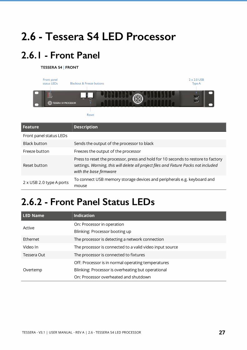
2.6 - Tessera S4 LED Processor
2.6.1 - Front Panel
Feature Description
Front panel status LEDs
Black button Sends the output of the processor to black
Freeze button Freezes the output of the processor
Reset buttonPress to reset the processor, press and hold for 10 seconds to restore to factory settings. Warning, this will delete all project files and Fixture Packs not included with the base firmware
2 x USB 2.0 type A portsTo connect USB memory storage devices and peripherals e.g. keyboard and mouse
2.6.2 - Front Panel Status LEDsLED Name Indication
ActiveOn: Processor in operation
Blinking: Processor booting up
Ethernet The processor is detecting a network connection
Video In The processor is connected to a valid video input source
Tessera Out The processor is connected to fixtures
Overtemp
Off: Processor is in normal operating temperatures
Blinking: Processor is overheating but operational
On: Processor overheated and shutdown

28 TESSERA - V3.1 | USER MANUAL - REV A | 2.6 - TESSERA S4 LED PROCESSOR
2.6.3 - Rear Panel Connections
Feature Description
Management Ethernet Connect a PC or Mac running the Tessera Remote, Tessera Control application or an eDMX protocol directly to the local data Gigabit Ethernet port.
Local User Interface The Tessera S4 LED Processor can be operated locally with a monitor connected via DisplayPort. Peripherals such as mouse and keyboard can be connected to the USB ports on either the front or rear panel.
DVI Input A DVI input of up to 1920x1080 @ 60Hz (148.5MHz pixel clock) is supported. This is a DVI-D input, with a re-clocked DVI-D thru. See Canvas Resolutions on page 65 for more information.
Gigabit Ethernet Outputs
The Tessera S4 LED Processor has four 1 Gigabit Ethernet outputs which are provided on EtherCON connectors. Fixtures must be connected using Gigabit Ethernet cable (Cat-5e or above). See System Configuration on page 35 for more information.
On/Off Switch The processor can be shut down from the local interface or remote computer. No harm will result from turning the processor off at the switch.
IEC Mains Input The input is auto ranging from 100-250v/47-63Hz

TESSERA - V3.1 | USER MANUAL - REV A | 2.7 - TESSERA T1 LED PROCESSOR 29
2.7 - Tessera T1 LED Processor
2.7.1 - Front Panel
Feature Description
Front panel status LEDs
Reset buttonPress to reset the processor, press and hold for 10 seconds to restore to factory settings. Warning, this will delete all project files and Fixture Packs not included with the base firmware
2 x USB 2.0 type A portsTo connect USB memory storage devices and peripherals e.g. keyboard and mouse
2.7.2 - Front Panel Status LEDsLED Name Indication
ActiveOn: Processor in operation
Blinking: Processor booting up
Ethernet The processor is detecting a network connection
DMX In A DMX signal is being received by the processor
Video In The processor is connected to a valid video input source
Tessera Out The processor is connected to fixtures
Black/Freeze Either the blackout or freeze button has been enabled
Overtemp
Off: Processor is in normal operating temperatures
Blinking: Processor is overheating but operational
On: Processor overheated and shutdown

30 TESSERA - V3.1 | USER MANUAL - REV A | 2.7 - TESSERA T1 LED PROCESSOR
2.7.3 - Rear Panel connections
Feature Description
Management EthernetConnect a PC or Mac running the Tessera Remote, Tessera Control application or an eDMX protocol directly to the local data Gigabit Ethernet port.
Local User InterfaceThe Tessera T1 LED Processor can be operated locally with a monitor connected via DisplayPort. Peripherals such as mouse and keyboard can be connected to the USB ports on either the front or rear panel.
DVI InputA DVI input of up to 1920x1080 @ 60Hz (148.5MHz pixel clock) is supported. This is a DVI-D input, with a re-clocked DVI-D thru. See Canvas Resolutions on page 65 for more information.
DMX 512-A Input For DMX real-time control.
Gigabit Ethernet Outputs
The Tessera T1 LED Processor has one 1 Gigabit Ethernet output which are provided on EtherCON connectors. Fixtures must be connected using Gigabit Ethernet cable (Cat-5e or above). See System Configuration on page 35 for more information.
On/Off SwitchThe processor can be shut down from the local interface or remote computer. No harm will result from turning the processor off at the switch.
IEC Mains Input The input is auto ranging from 100-250v/47-63Hz

TESSERA - V3.1 | USER MANUAL - REV A | SECTION 3 - QUICKSTART 31
SECTION 3 - QUICKSTARTFollow this chapter to get a basic system up and running. This guide covers starting a new project with fixtures connected. To set up a project offline and connect fixtures at a later stage. See Tessera Management Software on page 47 for more information.
3.1 - Tessera LED Processor Setup 1. a. S8,M2, T1 and S4 users: Connect fixtures to the Tessera output ports on the rear
panel of the processor using Gigabit Ethernet cable (Cat 5e or above) and network switches.
b. SX40 users: Connect the Tessera XD Unit to the processor using either copper or fibre optic cables. Fixtures are required to be connected to the Tessera XD Unit.
NOTE Tessera SX40 does not support sub-fixtures
2. Connect the video input source(s) to the DVI, HDMI and/or SDI input ports. 3. Connect a monitor to the Local UI using the DisplayPort connector and connect a mouse
and keyboard. Alternatively, access the processor's user interface through a Mac or Windows PC running the Tessera Remote application.
4. Connect the IEC mains input and switch the processor on. When the processor has powered up, the monitor displays the start screen. By default, the processor is configured to automatically load the previous project after a set amount of time if the user does not intervene.
Fig 3.1 - The Start Screen

32 TESSERA - V3.1 | USER MANUAL - REV A | 3.2 - TESSERA PROJECT SETUP
3.2 - Tessera Project Setup 1. From the Start Screen, select New to launch the Project Wizard.
Fig 3.2 - The New Project Wizard on a Tessera SX40 LED Processor
1. The project name can be manually entered, if no entry is made, a default project name containing the processor’s model with a date and time stamp is assigned.
2. Select a canvas size from the drop-down menu. When selecting a resolution other than the native 1920x1080, Tessera M2 and T1 LED Processors enforce Low Latency Mode.
3. Click Create to be taken to the Main Project Screen. 4. The project is only saved to the processor’s internal storage including when using Tessera
Remote in which case it will also be possible to manually save the project to the local computer.
Fig 3.3 - Main Project Screen

TESSERA - V3.1 | USER MANUAL - REV A | 3.3 - CONNECTING FIXTURES 33
3.3 - Connecting Fixtures
Fig 3.4 - Add Fixtures from Network button
1. Ensure that all fixtures are connected to the processor with the desired topology, taking into consideration the output port’s capacity limit.
2. Click the Add Fixtures From Network button. The canvas toolbar is replaced with a row of currently connected fixtures. When using Add Fixtures From Network, strings of fixtures are highlighted with colours corresponding to the ones shown in the UI. Each string is assigned a unique numeric code which appears on the first fixture of the string during association.
Fig 3.5 - The Add Fixtures From Network toolbar, the right-side shows connected fixtures whilst in Add Fixtures From Network menu.
3. Entering this code on the processor (using number keys or numpad) selects the corresponding string for association. The string is then ready to be drawn in the canvas using the cursor.
Fig 3.6 - Associating Fixtures
Fig 3.7 - A highlighted Recoloured string
4. The first fixture in the string is highlighted white, while other fixtures display varying shades of the same colour to denote the order of the fixtures in the string - from brightest to darkest.

34 TESSERA - V3.1 | USER MANUAL - REV A | 3.3 - CONNECTING FIXTURES
5. Click on the canvas to add fixtures one by one. The currently selected fixture is highlighted in white on the LED panel.
6. Clicking and dragging will draw an array of fixtures. The topology is defined by the direction taken when drawing the array.
7. Repeat the process for all strings, then press Enter or click the Back arrow to return to the Main Project Screen.
8. Fixtures on the canvas display a green circle to indicate online status. If the input source is connected, the fixtures will output video.

TESSERA - V3.1 | USER MANUAL - REV A | SECTION 4 - SYSTEM CONFIGURATION 35
SECTION 4 - SYSTEM CONFIGURATION
4.1 - Connecting FixturesTessera LED Processors drive Tessera compatible devices. Tessera compatible fixtures are fitted with a Tessera R2 Receiver Card inside, either in each tile or cabinet, or in a root node connected to strings of sub-fixtures.
All Tessera compatible fixtures have two gigabit Ethernet ports: one to connect to the processor and one to connect to the next device in the chain. These ports are interchangeable for convenience.
The processor communicates with fixtures on the network using the Tessera Protocol . The system topology requires fixtures to be connected to the HD processor or Tessera XD Distribution Unit. Once connected, a group of fixtures in a daisy-chain becomes a string.
NOTE Tessera Protocol only supports gigabit ethernet compliant equipment and does not function with 100BASE-T (Fast Ethernet) or 10BASE-T. The 10 gigabit connection between the Tessera XD and SX40 LED Processor must be direct, using fibre optic or Cat6a or above cabling. See Cable Requirements For Tessera SX40 and XD on page 257 for more information.
4.2 - Connection Guidelines
4.2.1 - 1 Gigabit Data ConnectionTessera devices need to be connected to the HD processor or XD Unit directly or via a gigabit ethernet network switch, using cables that conform to Cat5e or above and include RJ45 and EtherCON terminations.
The maximum supported individual cable length is 100 meters. The Tessera Protocol can be transmitted over standard gigabit ethernet compliant fibre optic hardware for single runs exceeding this distance.
The suggested maximum number of nodes between the processor and the furthest fixture in any system is five switches and 50 fixtures (Tessera XD Units and fibre optic transceivers count

36 TESSERA - V3.1 | USER MANUAL - REV A | 4.2 - CONNECTION GUIDELINES
as switches). By using switches, up to 500 fixtures can be run from a Tessera LED Processor output port (assuming this does not exceed the pixel limit of the output).
NOTE The Tessera Protocol does not support connection over Wi-Fi due to the bandwidth required to alter content and fixtures.
4.2.2 - 10 Gigabit Data ConnectionThe connection between the Tessera SX40 LED Processor and its Tessera XD Distribution Units needs to be direct by using single-mode fibre-optic cables with PC or UPC DUO connectors for a length of up to 2 km or Cat6a or above cabling with RJ45 or EtherCON terminations to reach a maximum distance of 60 m.

TESSERA - V3.1 | USER MANUAL - REV A | 4.3 - REDUNDANCY CONFIGURATION 37
4.3 - Redundancy Configuration
4.3.1 - Closed Loop RedundancyClosed loop redundancy is supported on Tessera SX40, Tessera S8, M2 and S4 LED Processors where two outputs can be configured to operate as a redundant pair. Closed loop redundancy is not supported on Tessera T1 LED Processors as they only feature a single output.
For closed loop redundancy, a cabling loop is created from the primary port, through a string of fixtures, and then back to the processor. One output acts as the primary port, while the second output acts as the backup. In the case of signal loss or errors with the primary feed, the backup port takes control and re-allocates fixtures to use the backup feed. The change is done within one frame, ensuring live content continues to display in the event of failures occurring anywhere in the loop.
Fig 4.1 - Tessera LED Processor setup with redundancy
The load capacity for each redundant pair is the same as for a single non-redundant trunk. Redundancy is only available from port 1 to port 2, and from port 3 to port 4.
Once the system has been cabled correctly, click on the Network pipeline tile. Under redundancy the user can enable redundancy for connected trunks. The processor is also able to detect faults with cabling and reports Loop OK or Errors Detected for connected trunks.
38 TESSERA - V3.1 | USER MANUAL - REV A | 4.3 - REDUNDANCY CONFIGURATION
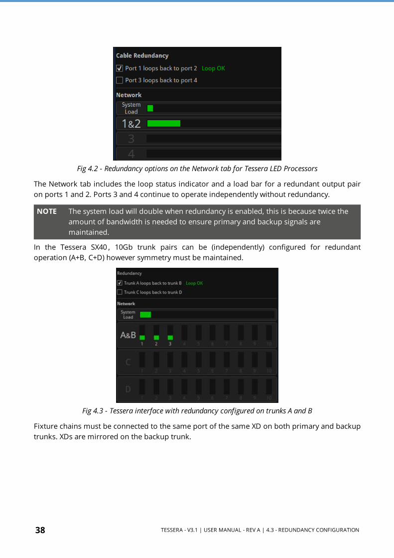
Fig 4.2 - Redundancy options on the Network tab for Tessera LED Processors
The Network tab includes the loop status indicator and a load bar for a redundant output pair on ports 1 and 2. Ports 3 and 4 continue to operate independently without redundancy.
NOTE The system load will double when redundancy is enabled, this is because twice the amount of bandwidth is needed to ensure primary and backup signals are maintained.
In the Tessera SX40 , 10Gb trunk pairs can be (independently) configured for redundant operation (A+B, C+D) however symmetry must be maintained.
Fig 4.3 - Tessera interface with redundancy configured on trunks A and B
Fixture chains must be connected to the same port of the same XD on both primary and backup trunks. XDs are mirrored on the backup trunk.

TESSERA - V3.1 | USER MANUAL - REV A | 4.3 - REDUNDANCY CONFIGURATION 39
Fig 4.4 - Tessera SX40 configured with redundancy for trunks A and B and C and D
When operating in redundancy mode:
l Fixtures can be cabled in a single chain of up to 50 fixtures, with each end of the chain connected back to the processor (or Tessera XD when using a Tessera SX40). Ethernet switches must not be used to split the signal. Other Ethernet hardware (such as fibre extenders) are supported.
l Closed loop redundancy should be enabled on the processor. l The output capacity limits that apply to a single port also apply to the pair of ports. This
effectively halves the overall processor capacity, as each output signal is being 'doubled up'. This also applies to Tessera SX40, therefore twice the amount of Tessera XD Units would be required.
l The total network load for the two ports combine into a single bar indicating the load for that pair.
l Switching in and out of redundancy mode will momentarily black-out the video signal for all connected fixtures on all ports. Redundancy mode should be configured in advance.
l The active feed (primary or backup) used by each fixture can be viewed in the Online tab. l If both the primary and backup signals are operational, each fixture can alternate between
either signal. If a fixture receives a video error or complete signal loss from one port, it will switch to the backup port for the next frame.
l For Tessera S8, S4, and M2 LED Processors, each loop must be cabled between the two adjacent ports on the same processor. (I.e. Port 1 to Port 2, and Port 3 to Port 4.)
l For Tessera SX40, the loop is created using the same trunk port number in two adjacent Tessera XD Units (i.e. Trunk A to Trunk B, and Trunk C to Trunk D)

40 TESSERA - V3.1 | USER MANUAL - REV A | 4.3 - REDUNDANCY CONFIGURATION
4.3.2 - Processor RedundancyOnly available for the Tessera SX40, processor redundancy is designed as a backup system should the primary processor fail to send a signal to the fixtures. If the primary processor stops outputting video signal, the backup processor will detect the fault and re-associate fixtures. Fixtures will lose video signal momentarily and will automatically resume within 1-2 seconds.
Different types of failure can trigger failover including; power issues, closing project, loss of input signal, processor failure, or if failover is activated by the user.
To set up processor redundancy:
1. Connect the primary and backup processor to the X1 and X2 ports of the XD Units. 2. Enable failover in the failover tab of both processors. 3. Select the role of each processor, either primary or backup. 4. Different criteria can be set for auto-failover behaviour:
l If the primary processor fails for (x) seconds The backup processor takes control if the primary processor’s Tessera output is missing for (x) seconds.
l If the primary video source is lost for (x) seconds The backup processor takes control if the primary processor’s video feed is missing for (x) seconds.
l If both front panel buttons are pressed together Failover can be triggered manually by pushing both front panel buttons at the same time.
l Processor redundancy can be activated by pushing the Failover button in the UI.
Fig 4.5 - An example of failover settings.
5. Video input cabling o Both processors may be fed from the same video source if required. HDMI/SDI thru
can be used but isn't recommended; an upstream splitter is preferable. o Each processor may be fed from a completely independent video source if required.
These may be different formats (HDMI/SDI), resolutions, framerates, etc. - there's no requirement for any aspect of the sources to match.

TESSERA - V3.1 | USER MANUAL - REV A | 4.3 - REDUNDANCY CONFIGURATION 41
o External reference signals (if in use) may similarly be shared or independent between the two processors.
6. Both processors must be set up independently of each other. Set the project in both processors to display the desired image. Settings such as fixture position in the canvas, video input and colour correction can be modified independently, so precautions should be taken to avoid differences between processors. Using the same settings with the same video source is advised. It is a good practice to use the same show-file in both processors, making sure that one is set as primary and the other one as backup.
Fig 4.6 - Processor redundancy
Processor redundancy is compatible with closed loop redundancy, offering different setup possibilities based on the system requirements.

42 TESSERA - V3.1 | USER MANUAL - REV A | 4.3 - REDUNDANCY CONFIGURATION
Fig 4.7 - Tessera SX40 LED Processor and loop redundancy
TESSERA - V3.1 | USER MANUAL - REV A | 4.4 - OUTPUT CAPACITY 43
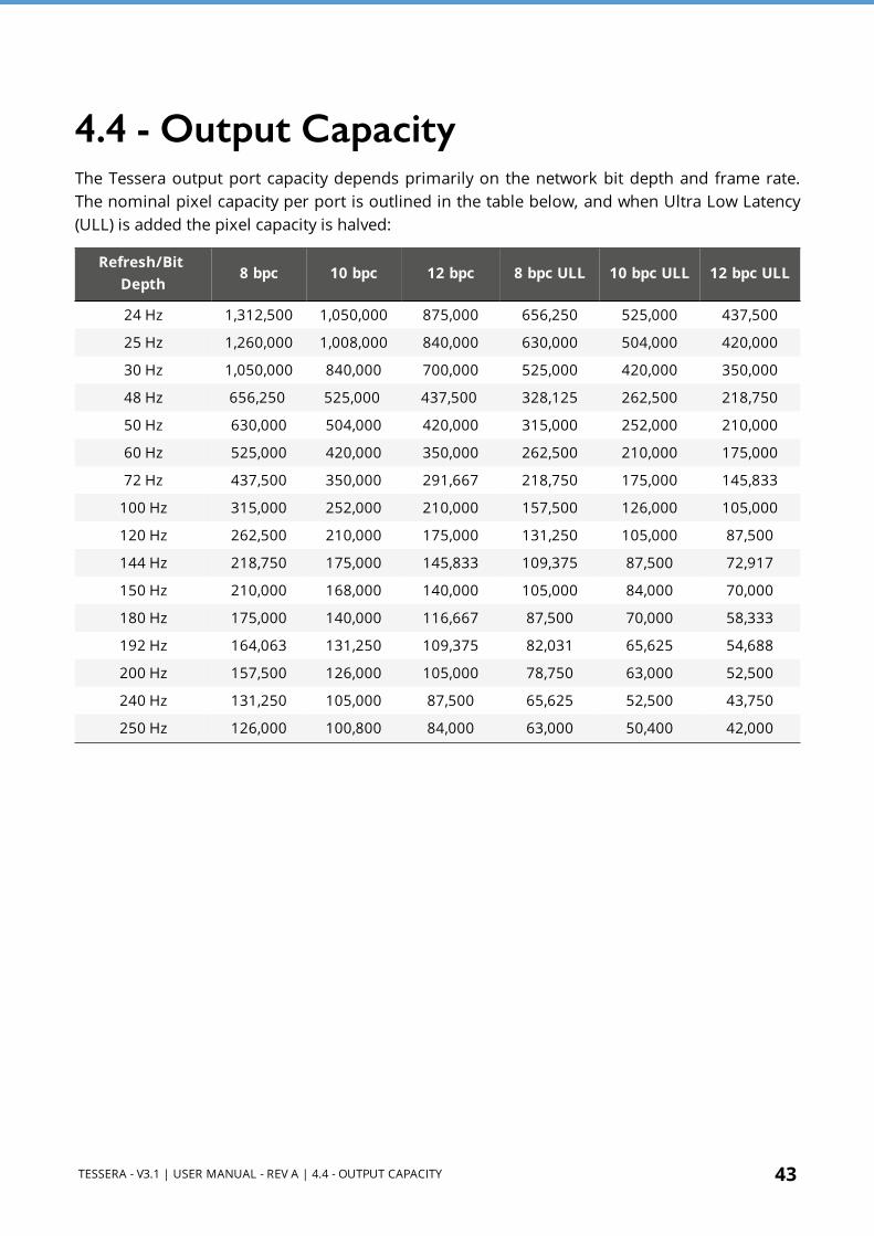
4.4 - Output CapacityThe Tessera output port capacity depends primarily on the network bit depth and frame rate. The nominal pixel capacity per port is outlined in the table below, and when Ultra Low Latency (ULL) is added the pixel capacity is halved:
Refresh/Bit Depth
8 bpc 10 bpc 12 bpc 8 bpc ULL 10 bpc ULL 12 bpc ULL
24 Hz 1,312,500 1,050,000 875,000 656,250 525,000 437,500
25 Hz 1,260,000 1,008,000 840,000 630,000 504,000 420,000
30 Hz 1,050,000 840,000 700,000 525,000 420,000 350,000
48 Hz 656,250 525,000 437,500 328,125 262,500 218,750
50 Hz 630,000 504,000 420,000 315,000 252,000 210,000
60 Hz 525,000 420,000 350,000 262,500 210,000 175,000
72 Hz 437,500 350,000 291,667 218,750 175,000 145,833
100 Hz 315,000 252,000 210,000 157,500 126,000 105,000
120 Hz 262,500 210,000 175,000 131,250 105,000 87,500
144 Hz 218,750 175,000 145,833 109,375 87,500 72,917
150 Hz 210,000 168,000 140,000 105,000 84,000 70,000
180 Hz 175,000 140,000 116,667 87,500 70,000 58,333
192 Hz 164,063 131,250 109,375 82,031 65,625 54,688
200 Hz 157,500 126,000 105,000 78,750 63,000 52,500
240 Hz 131,250 105,000 87,500 65,625 52,500 43,750
250 Hz 126,000 100,800 84,000 63,000 50,400 42,000
44 TESSERA - V3.1 | USER MANUAL - REV A | 4.4 - OUTPUT CAPACITY
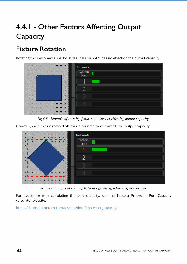
4.4.1 - Other Factors Affecting Output Capacity
Fixture RotationRotating fixtures on-axis (i.e. by 0°, 90°, 180° or 270°) has no effect on the output capacity.
Fig 4.8 - Example of rotating fixtures on-axis not effecting output capacity.
However, each fixture rotated off-axis is counted twice towards the output capacity.
Fig 4.9 - Example of rotating fixtures off-axis effecting output capacity.
For assistance with calculating the port capacity, see the Tessera Processor Port Capacity calculator website:
https://dl.bromptontech.com/tessera/docs/processor_capacity/

TESSERA - V3.1 | USER MANUAL - REV A | 4.4 - OUTPUT CAPACITY 45
Mapping Mode for Projects With Multiple FixturesThe Tessera M2 and T1 LED Processors can use different mapping modes to fit the project’s necessities. The Tessera SX40 and S4, always work with 1:1 mapping.
1:1 mapping doesn’t affect the output capacity. This mode sends the pixels of the input to the fixtures without taking into consideration the fixture size, only the pixel number.
When using interpolated mapping, the content on fixtures with a coarser pixel pitch is scaled so that the content appears the same size across all fixtures. In this mode, all fixtures are assumed to have the same pixel pitch as the finest fixture, and the output capacity is calculated according to the physical dimensions of the fixture. See Mapping Options on page 68 for more information.
Small FixturesSmall fixtures - with either dimensions smaller than 16 pixels - have a high processing overhead. Therefore, the number of these fixtures supported may be fewer than that calculated from the nominal pixel capacity.
In terms of processing, the Tessera SX40 LED Processor considers any connected fixture to be at least 64px in either dimension, so the total number of fixtures per port might be affected.
Estimating Fixture CapacityWhen associating fixtures to a project, network load bars display the output capacity on each port. The UI updates in real time as settings such as network bit depth, genlock frame rate and fixture rotations are applied. See Network on page 212 for more information.
Fig 4.10 - Network property editor showing system load and port load
To help with estimating the number of processors required for a project, we have created a simple web- based calculator tool which models all the factors outlined above. For further details, please contact support at: [email protected]

46 TESSERA - V3.1 | USER MANUAL - REV A | 4.5 - COMBINING PROCESSORS
4.5 - Combining ProcessorsThe Tessera SX40, S8, S4, T1, and M2 LED Processors are designed to be used together in a configuration without issues. Different types of processors can be used to run different sections of the same wall.
When combining processors, to avoid tearing, it is important to synchronize them by matching their end to end delay and genlocking the sources.
The end to end delay of the different processors is:
SX402 frames
1 frame with "Ultra Low Latency" on page 219
S82 frames
1 frame with "Ultra Low Latency" on page 219
S4 2 frames (this processor is always in low latency mode)
T13 frames
2 frames in "Low Latency Mode" on page 67
M23 frames
2 frames in "Low Latency Mode" on page 67
When working with different types of processors, the video latency requires re-adjusting per processor.
I.e. If using T1 and SX40 LED Processors together, a frame of latency will have to be added to the SX40 LED Processors, initially with 2 frames latency, to match the 3 frames of latency of the T1. Or the Tessera T1 can be put into "Low Latency Mode" on page 67 to bring it to 2 frames like the SX40.
The processors need to be genlocked to the same source or to each other.
See Network on page 212 for more information.
NOTE Please note that the difference in features between processors still apply. The Tessera SX40 does not have Low Latency mode but the scaler is disabled when using custom resolutions. See Low Latency Mode on page 67 for more information about the limitations of working in Low Latency Mode.
TESSERA - V3.1 | USER MANUAL - REV A | SECTION 5 - TESSERA MANAGEMENT SOFTWARE 47
SECTION 5 - TESSERA MANAGEMENT SOFTWAREThe Tessera Management Software is used to configure and control all aspects of Tessera LED Processors. The user interface can be accessed in two ways – locally with the use of a monitor, mouse and keyboard, or remotely using the Tessera Remote application.
The user interface is consistent across both access methods, with only subtle differences in functionality.
5.1 - Local User Interface When using the local user interface on the processor itself, no external computer is required.
To view the user interface, connect a monitor to the local UI port on the rear of the processor. DisplayPort monitors are natively supported, other connection types require an adapter. Once connected, the native resolution of the monitor is automatically detected. To change the default resolution, navigate to Settings > Processor, select a resolution from the dropdown menu and click Commit. The minimum supported resolution for M2 , T1 , and S4 LED Processors is 1024x768 and the maximum resolution is 1920x1080. The Tessera S8 and Tessera SX40 LED Processor support UI resolutions of up to 3840x2160.
The user interface is controlled by connecting a mouse and keyboard to the processor’s USB ports.
5.2 - Tessera Remote and Offline Editor Tessera Remote is a Windows PC and Mac OS application that allows remote control of Tessera LED Processors across a network. Additionally, the Remote application can be used as an ‘offline editor’ allowing the set up and editing of Tessera projects when not connected to a processor.
The main difference in functionality when working with the Tessera Remote app (not offline) is that the video on canvas edit modes are not available.
Tessera Remote is free to download from the Brompton Technology website:
http://bromptontech.com/support

48 TESSERA - V3.1 | USER MANUAL - REV A | 5.3 - INSTALLATION FOR WINDOWS PC
Tessera Remote software versions and the processor firmware versions must match. If the processor firmware version and Tessera Remote do not match, the firmware or remote software must be updated. The processor firmware can be updated from the remote app.
5.3 - Installation for Windows PC 1. Download Tessera Remote Windows software from our Brompton Support web page:
https://www.bromptontech.com/support 2. Open the downloaded file to begin Setup Wizard. Hit Next to continue.
3. The setup wizard asks for an install location, once selected click Next to begin the installation.
4. When the application has finished installing, a completion dialog box is displayed. Tick the ‘Run Tessera Remote’ box to launch the application after clicking Finish.

TESSERA - V3.1 | USER MANUAL - REV A | 5.3 - INSTALLATION FOR WINDOWS PC 49
50 TESSERA - V3.1 | USER MANUAL - REV A | 5.4 - INSTALLATION FOR MAC OS X
5.4 - Installation for Mac OS X 1. Download Tessera Remote Mac OSX installation file from Brompton ’s website
https://www.bromptontech.com/support 2. Double click the .dmg file and drag the Tessera Remote icon into the Applications Folder,
or copy (⌘ + C) and Paste (⌘ + V) the Tessera Remote icon into Applications folder 3. Multiple software versions of Tessera Remote Application can be installed on the same
Mac computer. It can be helpful to store these in different folders within the Applications folder.
5.5 - Network Settings for Remote ManagementTo connect a computer to a Tessera LED Processor, connect to the same network via Ethernet by setting the computer and processor to the same subnet mask and IP range. As the Tessera LED Processor’s remote network port supports Auto MDI-X, this network can be as simple as using a Cat 5e cable connected to the Mac or Windows PC without the need for a switch.
The default IP settings for the processor are 192.168.0.50, with a subnet mask of 255.255.255.0.
See Setting IP Addresses on page 260 for more information on setting IP addresses on Windows and Mac OS.
NOTE Due to the bandwidth limitations and reliability, wireless connections are not supported within the Tessera systems.

TESSERA - V3.1 | USER MANUAL - REV A | 5.6 - CONNECTING TO A TESSERA LED PROCESSOR 51
5.6 - Connecting to a Tessera LED ProcessorHaving physically connected a Mac or Windows PC to a Tessera LED Processor via network, launch the Tessera Remote application. This will open a dialogue box to start Tessera Remote or the Offline Editor.
Fig 5.1 - Start up menu for Tessera Remote
Click ‘Start Tessera Remote’ to start the application in Remote mode.
The application automatically detects connected processors on the network. Note the Tessera Remote software version. If it does not match the processor firmware version, reload processor firmware or install a matching Tessera Remote software version.
Fig 5.2 - Tessera Remote main menu with processor select options.

52 TESSERA - V3.1 | USER MANUAL - REV A | 5.6 - CONNECTING TO A TESSERA LED PROCESSOR
When reloading processor firmware, the processor is temporarily inaccessible while firmware is written to the processor. Once this process is complete, the processor will reboot before becoming accessible again.
Discovered processors display the following details:
l User-defined name of the processor l Firmware version l Processor type l IP address l Project file that is currently in use
To connect to the processor, double click the processor, or select a processor and click Connect.
5.6.1 - Tessera Remote SettingsThe Tessera Remote offline mode Settings menu contains preferences which allow general customisation of the canvas, Fixture Packs management and selection settings within Tessera Remote. These settings are stored locally and not applied to the processor itself.
Fig 5.3 - Tessera Remote settings menu
Once connected to the processor, the Remote application functions in a very similar way to the local user interface. See Processor Settings on page 233 for more information about the various settings.
When Tessera Remote is connected to the processor, the Local Management app running on the processor cannot be used. Take control of the processor by clicking the Take Control icon.

TESSERA - V3.1 | USER MANUAL - REV A | 5.6 - CONNECTING TO A TESSERA LED PROCESSOR 53
5.6.2 - Disconnecting From the ProcessorWhen closing the app or disconnecting from the processor, several options can be selected.
Closing the app:
Fig 5.4 - Tessera Remote, closing the app options
Disconnecting from the processor:
Fig 5.5 - Tessera Remote, disconnection from processor options.
l Clicking “Leave the project open on the processor” will return control to the processor’s local UI while keeping the project open.
l Clicking “Close the project on the processor” and return control to the processor’s local UI and closes the current project. The user will see the project management screen on the local UI.
l Clicking “Disconnect from the processor” to return control to the processor’s local UI.
54 TESSERA - V3.1 | USER MANUAL - REV A | 5.6 - CONNECTING TO A TESSERA LED PROCESSOR
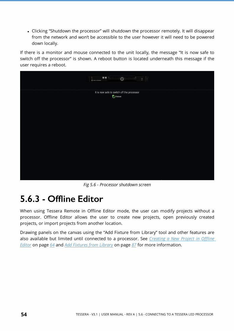
l Clicking “Shutdown the processor” will shutdown the processor remotely. It will disappear from the network and won’t be accessible to the user however it will need to be powered down locally.
If there is a monitor and mouse connected to the unit locally, the message “It is now safe to switch off the processor” is shown. A reboot button is located underneath this message if the user requires a reboot.
Fig 5.6 - Processor shutdown screen
5.6.3 - Offline EditorWhen using Tessera Remote in Offline Editor mode, the user can modify projects without a processor. Offline Editor allows the user to create new projects, open previously created projects, or import projects from another location.
Drawing panels on the canvas using the “Add Fixture from Library” tool and other features are also available but limited until connected to a processor. See Creating a New Project in Offline Editor on page 64 and Add Fixtures from Library on page 87 for more information.

TESSERA - V3.1 | USER MANUAL - REV A | 5.7 - MULTIPLE PROCESSORS CONTROL 55
5.7 - Multiple Processors ControlThere are different approaches to control multiple processors:
Use a single Tessera Remote instance - It is easy to connect and disconnect from different processors on a network. The output from the processors will continue uninterrupted when Tessera Remote is not connected.
Use multiple Tessera Remote instances - Although Tessera Remote only supports connection to one processor at a time, it is possible to run several instances of Tessera Remote on the same computer for remote control of several processors from one device.
Use the Tessera Control application - Tessera Control provides a simple user interface for controlling multiple processors simultaneously. Controls available include Global colour, input colour and presets. See Tessera Control on page 231 for more information.
Use DMX and eDMX Control – Several control profiles are available and can be customised to control adjustments in colour, position, rotation, presets, etc. See DMX Control on page 228 for more information.

56 TESSERA - V3.1 | USER MANUAL - REV A | 5.7 - MULTIPLE PROCESSORS CONTROL
5.7.1 - Running Multiple Instances of Tessera RemoteWhen controlling multiple processors from one computer it is recommended to use a fixed IP address on each processor and on the computer running Tessera Remote. It can also be helpful to name each processor. See Identification on page 234 for more information.
Controlling different processors is then as straightforward as ‘tabbing’ (Alt + Tab in Windows, ⌘ + Tab in Mac OSX) to the relevant instance of Tessera Remote as required. Several monitors can also be used to control different instances at the same time.
NOTE Mac OSX - To start Tessera Remote so that multiple instances can be run it is necessary to run Terminal in Utilities. In Terminal, type: open /applications/remote.app then press Enter. To run another instance of Tessera Remote type the following into Terminal: open -n /applications/remote.app
Fig 5.7 - Alt-Tab to monitor or swtich through multiple instances of Tessera Remote

TESSERA - V3.1 | USER MANUAL - REV A | SECTION 6 - HIGH DYNAMIC RANGE 57
SECTION 6 - HIGH DYNAMIC RANGE
The Tessera SX40 and S8 LED Processors are capable of accepting and delivering the impressive image quality of HDR on LED screens.
From Tessera version 3.0 onward High Dynamic Range output is fully featured and optimised with an updated processing pipeline offering enhanced processing capabilities and new exclusive features.
6.1 - Supported HDR Formats
Fig 6.1 - PQ, HLG, and SDR brightness curves
The supported HDR formats on the Tessera SX40 and S8 LED Processors are:
l PQ: PQ-HDR10 as specified by ST 2084 l HLG: Hybrid Log Gamma
SDR: Standard Dynamic Range is also accepted. These formats can be received via either the HDMI 2.0 or 12G-SDI inputs.

58 TESSERA - V3.1 | USER MANUAL - REV A | 6.2 - HDR FEATURES
All standard industry colour spaces are compatible (Rec.2020, DCI-P3, Rec.709) as well as custom ones that can also be created on-the-fly. See Dynamic Calibration (DynaCal) User Interface on page 199 for more information.
6.2 - HDR FeaturesTo fully deliver the impressive benefits of HDR content Dynamically Calibrated LED panels, using our Hydra Camera System, are required as they allow the full spectrum of brightness and colour saturation to be accessed. See Dynamic Calibration on page 59 for more information.
The Tessera SX40 and S8 LED Processors accept HDR video input at up to 12 bits per colour, and can automatically detect the input signal properties via InfoFrames on the HDMI 2.0 port. All received metadata about the HDR source is also now visible from the input source tile. See Input Metadata on page 138 for more information.
How the SX40 and S8 LED Processors interpret and handle HDR video can be flexibly controlled via the input controls available from the input source tile. See Input Override on page 142 for more information.
Thanks to the dynamic nature of Dynamic Calibration parameters such as brightness and colour space (or colour targets) can be adjusted on-the-fly from the Dynamic Calibration User Interface. See Dynamic Calibration (DynaCal) User Interface on page 199 for more information.
HDR is fully compatible with all Tessera features including the two new Dynamic Calibration-enabled perfomrance-enhancing features of PureTone and ThermaCal. These are designed to ensure the incoming content is displayed exactly as it was intended to be seen by viewers. See PureTone on page 183 and ThermaCal on page 78 for more information.
The EDID for the Tessera SX40 and S8 LED Processors can be modified to signal to the source that they are capable of receiving HDR video provided the LED panels being used also support it (and have been Dynamically Calibrated). See Enable HDR on page 65 for more information.

TESSERA - V3.1 | USER MANUAL - REV A | 6.3 - DYNAMIC CALIBRATION 59
6.3 - Dynamic Calibration
Dynamic Calibration is a Brompton Technology made feature designed to unlock the full potential of LED panels to achieve previously unattainable image quality results. It is a completely new approach to calibrating LED panels that allows users to achieve unthinkable brightness levels and colour saturation. With Dynamically Calibrated panels Brompton users have unprecedented control over their panels and with the ability to tailor the final image to their needs, and it allows this to be done on-the-fly.
Dynamic Calibration achieves this by using a Brompton designed calibration process that does not lock the panel to a fixed calibration, as is done by calibration methods that are commonly used in the LED panel manufacturing processes.
Dynamic Calibration is a fundamental feature- enabling technology that is required for the following features to be delivered:
l "High Dynamic Range" on page 57. l "PureTone" on page 183. l "ThermaCal" on page 78.
The above features will only be available when using Dynamically Calibrated LED panels together with our Tessera LED Processors. Refer to Device Properties on page 74 for details on how to enable a Dynamic Calibration on Dynamically Calibrated LED panels. Refer to Dynamic Calibration (DynaCal) User Interface on page 199 for details on the DynaCal UI and using Dynamic Calibration features.
To find out more about Dynamic Calibration you can watch our Dynamic Calibration Feature Spotlight Video (https://youtu.be/6lifet_fFoo).

60 TESSERA - V3.1 | USER MANUAL - REV A | 6.3 - DYNAMIC CALIBRATION
6.3.1 - Technical Aspects of Dynamic CalibrationAll the features explained in this section that are associated with Dynamic Calibration are available exclusively to all Tessera LED Processors provided they are connected to Dynamically Calibrated LED panels.
Dynamic Calibration is required in order to deliver "High Dynamic Range" on page 57. This is currently only available on the Tessera SX40 and S8 LED Processors and either Processor needs to be connected to LED panels that have been Dynamically Calibrated to deliver the full benefits of "High Dynamic Range" on page 57.
To be Dynamically Calibrated LED panels need to meet 2 requirements:
1. The LED panels need to be fitted (and compatible) with a Tessera R2 Receiver Card. 2. The LED panels need to be calibrated using our Hydra Camera System.
The Hydra Camera System is a Brompton designed calibration system required to achieve Dynamic Calibration. To find out more about the Hydra Camera System please visit our Hydra - Brompton Website (https://www.bromptontech.com/technology/hydra/).
For information about Dynamically Calibrating LED panels and panel compatibility with Dynamic Calibration please contact our Brompton Team at [email protected].

TESSERA - V3.1 | USER MANUAL - REV A | SECTION 7 - PROJECT SETUP 61
SECTION 7 - PROJECT SETUP
7.1 - Project Management
7.1.1 - Opening and Importing ProjectsSelect a project from the list then click Open from the left menu. You can also import projects from USB drives or the local computer storage drive.
Fig 7.1 - Importing projects in the project management screen
To import a project using the processor:
1. Insert a USB flash drive containing the project file into a USB port of the processor. 2. Click Open on the project management screen to display the File Browser. 3. Navigate to a project file, select and click OK. The project file is copied and displayed in the
list of projects stored on the processor. 4. Double click the file to open it.
To import a project while connected to the processor via Tessera Remote:
1. Click Import Project to open a file browser window and navigate to the project file stored on the computer.

62 TESSERA - V3.1 | USER MANUAL - REV A | 7.1 - PROJECT MANAGEMENT
2. Select the file and click OK. The project file is copied to the list of projects stored on the processor.
7.1.2 - Exporting ProjectsIn the remote app, to export a project stored in the processor, select the desired project from the project management screen and click Export project to select the location. When the project is open, pressing Save as… allows the user to save the project on the processor and on the local computer. Save a copy, saves to the computer.
Fig 7.2 - Exporting projects in the project management window.
In the Local user interface, projects can be exported to a USB drive.
1. Insert a USB flash drive into a USB port of the processor. 2. Click Export project on the project management screen to display the file browser. 3. Navigate to the desired location, make selection and click OK.
7.1.3 - Deleting Projects Stored On the Processor
1. From the project management screen, click to individually select projects and click Delete Projects to remove the file.
2. To delete multiple projects, hold Ctrl + Shift and use the mouse cursor to select multiple files.

TESSERA - V3.1 | USER MANUAL - REV A | 7.1 - PROJECT MANAGEMENT 63
7.1.4 - Creating a New Project on Local UI and Tessera Remote
Fig 7.3 - The New Project window on a Tessera SX40
To start a new project, select New on the project management screen. Once the New Project Wizard launches:
1. Enter a project name 2. Select a canvas size, Low Latency mode is automatically enabled on Tessera T1 and M2
LED Processors if canvas sizes other than 1920x1080 are used. Ticking the Enable HDR checkbox will modify the EDID of the processor (SX40 and S8) signalling to the source that it is able to receive HDR video.
3. The Tessera SX40 and S8 feature custom resolutions. See Custom Canvas Resolution on page 66 for more information.
4. Seam Brightness, Module Colour correction, Low Latency Mode, and Loop/Processor Redundancy can be enabled from this menu.
5. Click Create to move to canvas edit mode.
NOTE The project is automatically saved to the processor’s internal storage but can also be saved to a USB storage device. See Project Management on page 61 for more information.

64 TESSERA - V3.1 | USER MANUAL - REV A | 7.1 - PROJECT MANAGEMENT
7.1.5 - Creating a New Project in Offline Editor
Fig 7.4 - The offline editor’s New Project Wizard differs from Remote and Local UI mode
To start a new project, select New from the menu on the Main screen. Once the New Project Wizard launches:
1. Select the processor platform where the project is used. 2. Enter a project name and the location for the project file to be saved to. 3. Select a canvas size, Low Latency Mode is automatically enabled on Tessera T1 and M2
LED Processors if canvas sizes other than 1920x1080 are used. Ticking the Enable HDR checkbox will modify the EDID of the processor (SX40 and S8) signalling to the source that it is able to receive HDR video.
4. The Tessera SX40 and S8 feature custom resolutions. See Custom Canvas Resolution on page 66 for more information.
5. Seam Brightness, Module Colour Correction, Low Latency Mode and Loop or Processor Redundancy can be enabled from this menu.
6. Click Create to move to canvas edit mode.

TESSERA - V3.1 | USER MANUAL - REV A | 7.2 - ENABLE HDR 65
7.2 - Enable HDR
Fig 7.5 - Enable HDR checkbox in Project Setup (left) and Canvas Properties (right)
On the HDR capable Tessera SX40 and S8 LED Processors the Enable HDR feature can be enabled by ticking the checkbox located within either the New Project window (Local page 63 / Offline page 64 editor) or Canvas Properties (page 66) panel.
Enabling this feature changes the Processor EDID to tell the source that it supports HDR. The EDID is only sent to sources via the HDMI 2.0 connection.
NOTE This feature will only change the EDID of the Tessera SX40 and S8 LED Processors, both will always be able to receive HDR input.
If the LED panels being used do not support HDR it is recommended to keep this checkbox un-ticked.
NOTE Keeping this feature disabled does not guarantee the source will respect the EDID and only send SDR.
7.3 - Canvas ResolutionsTessera systems allow the source to send any input resolution that fits within the canvas size, except when working at 2880x720 or 720x2880 in the HD processors.
Tessera M2 / S4 / T1
l The native canvas size for processors is 1920x1080 pixels l The following list of non-standard canvas sizes are allowed, but places the processor in
Low Latency Mode. See Low Latency Mode on page 67 for more information. l 1080x1920 l 1600x1200 l 2880x720 – This resolution requires the input to match the canvas size l 720x2880 – This resolution requires the input to match the canvas size
Tessera SX40 / Tessera S8
l HD 1920x1080 l 4K DCI (4096x2160) or 4K UHD (3840x2160) can be selected as native resolutions. l Custom canvas resolutions are available.

66 TESSERA - V3.1 | USER MANUAL - REV A | 7.3 - CANVAS RESOLUTIONS
7.3.1 - Custom Canvas ResolutionOnly available for the Tessera SX40 and S8 LED Processors, the user can enter a canvas size of their choosing, unrestricted by aspect ratio.
Fig 7.6 - The Canvas Properties, the user can adjust the canvas size on the fly
There are some rules to bear in mind when using custom resolutions.
l Width: l Minimum: 720 pixels l Maximum: 4094 pixels l It must be an even value
l Height l Minimum: 720 pixels l Maximum: 4095 pixels
l The maximum total number of supported pixels is 8,847,460
Custom resolution settings should be thoroughly tested before being used in a production environment.

TESSERA - V3.1 | USER MANUAL - REV A | 7.4 - LOW LATENCY MODE 67
7.4 - Low Latency ModeLow Latency Mode reduces the overall latency by one frame.
Tessera T1 and M2 LED Processors work at a latency of 3 frames. In Low Latency Mode, the latency is reduced to 2 frames. Tessera S4 LED Processors are always in Low Latency Mode, and non-standard canvas sizes automatically switch the Tessera M2 and T1 LED Processors into Low Latency Mode.
NOTE When using several processors with different end to end latencies to run the same wall, video delay needs to be modified. See Combining Processors on page 46 for more information.
Working in this mode, the following features are disabled:
l Scaling (upscaling and downscaling). As a result, the active area modifications are disabled l Deinterlace l Frame-rate conversion, forcing the processor to lock to the source framerate
Colour functions, such as contrast, brightness and RGB gain remain unaffected. The input source is set at its default resolution and sync frequency and is positioned 1:1 in the top left corner of the canvas.
The Tessera SX40 and SX40 LED Processors do not have a Low Latency Mode, keeping all its features available at 2 frames latency end to end. To decrease their latency to 1 frame they can use Ultra Low Latency, though this has its own trade-offs. See Ultra Low Latency on page 219 for more information
NOTE Latency, or video delay, is defined as the time between the last cycle of a source frame appearing on the processor's input, and the first cycle that an LED on a fixture is lit with that frame.

68 TESSERA - V3.1 | USER MANUAL - REV A | 7.5 - MAPPING OPTIONS
7.5 - Mapping OptionsInterpolation can be activated from the Canvas properties. Tessera projects can be set to work in two different mapping modes depending on the requirements. See Canvas Properties on page 110 for more information.
When working in 1:1, the physical size and pixel pitch is not taken into account, every pixel is sent to the correspondent position, independently of the fixture size.
Fig 7.7 - Fixture output in 1:1 mode
In Interpolated mode, the physical size of panels is accounted for, interpolating every pixel to match the size of different panels, keeping the proportions of the image.
Fig 7.8 - Fixture output in Interpolated mode
NOTE Interpolation Mode is only avilable on the Tessera T1 and M2 LED Processors.
TESSERA - V3.1 | USER MANUAL - REV A | 7.5 - MAPPING OPTIONS 69
7.5.1 - Port Capacity in 1:1 or InterpolatedWhen using 1:1 mapping, the output capacity is not affected.
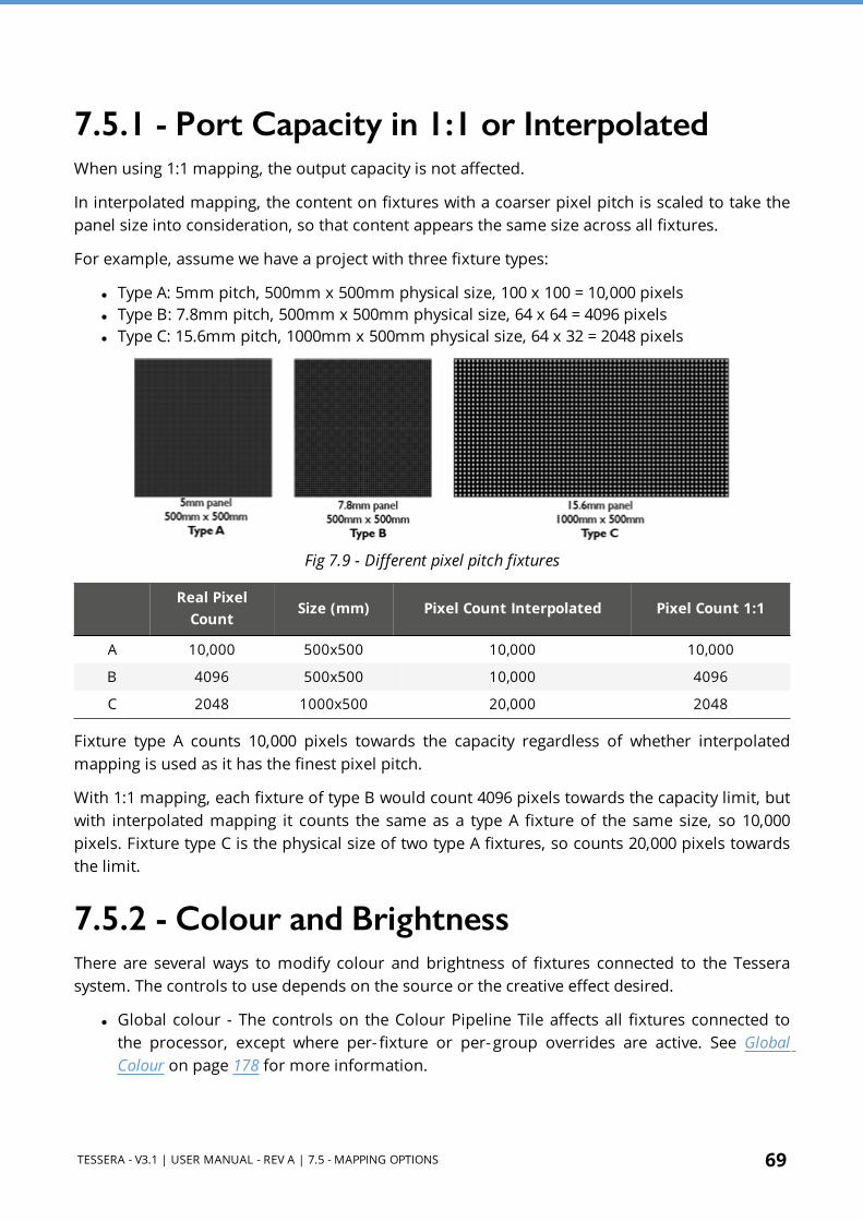
In interpolated mapping, the content on fixtures with a coarser pixel pitch is scaled to take the panel size into consideration, so that content appears the same size across all fixtures.
For example, assume we have a project with three fixture types:
l Type A: 5mm pitch, 500mm x 500mm physical size, 100 x 100 = 10,000 pixels l Type B: 7.8mm pitch, 500mm x 500mm physical size, 64 x 64 = 4096 pixels l Type C: 15.6mm pitch, 1000mm x 500mm physical size, 64 x 32 = 2048 pixels
Fig 7.9 - Different pixel pitch fixtures
Real Pixel
CountSize (mm) Pixel Count Interpolated Pixel Count 1:1
A 10,000 500x500 10,000 10,000
B 4096 500x500 10,000 4096
C 2048 1000x500 20,000 2048
Fixture type A counts 10,000 pixels towards the capacity regardless of whether interpolated mapping is used as it has the finest pixel pitch.
With 1:1 mapping, each fixture of type B would count 4096 pixels towards the capacity limit, but with interpolated mapping it counts the same as a type A fixture of the same size, so 10,000 pixels. Fixture type C is the physical size of two type A fixtures, so counts 20,000 pixels towards the limit.
7.5.2 - Colour and BrightnessThere are several ways to modify colour and brightness of fixtures connected to the Tessera system. The controls to use depends on the source or the creative effect desired.
l Global colour - The controls on the Colour Pipeline Tile affects all fixtures connected to the processor, except where per- fixture or per- group overrides are active. See Global Colour on page 178 for more information.

70 TESSERA - V3.1 | USER MANUAL - REV A | 7.5 - MAPPING OPTIONS
l Per- fixture and per- group colour override - Colour and brightness settings can be superseded for specific fixtures or groups by enabling Override Global Colour on the Fixture Properties editor. See Per-Fixture and Per-Group Colour Override on page 72 for more information.
l Input colour - provides controls for modifying the colour balance of a specific input (DVI, SDI or analogue). See Input Colour Control on page 146 for more information.
l On-Screen Colour Adjustment (OSCA) –OSCA provides a way of compensating for colour mis-matches between modules and the appearance of bright or dark seams. See On-Screen Colour Adjustment on page 186 for more information.
l ChromaTune - ChromaTune provides tools for making more precise tweaks to specific colours in an incoming video feed. See ChromaTune on page 168 for more information.

TESSERA - V3.1 | USER MANUAL - REV A | SECTION 8 - FIXTURES 71
SECTION 8 - FIXTURES
8.1 - Fixture LibrariesTo correctly communicate with fixtures, the processor needs to have the fixture firmware included in the fixture library of the processor. A Fixture Pack is installed with every version of the processor’s firmware and updated Fixture Packs can be found on our website. See Fixture Library on page 240 for more information.
8.2 - Fixture PropertiesWhen selecting an online fixture from the canvas or from the online tab, the Fixture property editor appears. The property editor sections are divided into Fixture, Colour and Device. See Properties Area on page 120 for more information.
Fig 8.1 - Fixture property editor

72 TESSERA - V3.1 | USER MANUAL - REV A | 8.2 - FIXTURE PROPERTIES
8.2.1 - FixtureFixture displays basic information about the selected fixture including manufacturer, fixture type and the name of the group containing the fixture.
The second section of this editor displays the position and rotation of the fixture in the canvas. Modifications can be made by typing or using the spin box arrows. Changes can be locked to avoid modifications. Reorient rotates square fixture by 90 degrees clockwise, rectangular fixtures are re-oriented by 180 degrees.
8.2.2 - ColourColour modifications can be enabled in the selected fixture independently from the Global Colour. When the Override Global Colour box is ticked, colour modifications for the selected fixture are enabled and Global Colour property editor values have no effect on the fixture.
8.2.3 - Per-Fixture and Per-Group Colour Override
Fig 8.2 - Global Colour Override options in Colour property editor
Single fixtures or groups of fixtures can be made exempt from Global Colour control and assigned separate values. This is useful to maintain one screen at a constant brightness when other fixtures are grouped into separate screens on a processor.
To Override Global Colour, select the fixtures or groups to override and choose from options from the property editor. Different options are made available depending on the users selection.
l If the selection is an ungrouped fixture or a combination of fixtures/groups, the options that can be adjusted are:
l Intensity gain l Red gain l Green gain l Blue gain
l If the selection is a group, the options that can be adjusted are:
TESSERA - V3.1 | USER MANUAL - REV A | 8.2 - FIXTURE PROPERTIES 73
l All the previous settings l Brightness l (Colour) Temperature l Gamma
NOTE Once a selection has been overridden on the Colour property editor, the Global Colour controls have no effect on the selected fixtures until the checkbox for Override Global Colour is unchecked.

74 TESSERA - V3.1 | USER MANUAL - REV A | 8.3 - DEVICE PROPERTIES
8.3 - Device PropertiesThe device property editor shows information stored on the R2 receiver card.
8.3.1 - Fixture Quick Access ButtonsIn the title bar for the Device property editor, there are three quick access buttons:
l Reset: Reboots the fixture, video will stop displaying in the following devices connected in the same string, as data is not passed through while the fixture is rebooting.
l Beacon: Activates the “Identify” test pattern, also called beacon, for the selected fixture. This can be used to identify the panel from the back. While the panel is in Beacon, the rear status indicator LED of the panels blinks yellow.
Fig 8.3 - A Beaconed panel showing the Identify internal test pattern
l Reload firmware: Re-applies firmware for selected fixtures from the prioritized pack in the Fixture Library. See Fixture Library on page 240 for more information.
8.3.2 - Device InformationThe first section lists the MAC address, serial number and firmware version information of the R2 receiver card. The OSD property editor can enable and control OSD shown on selected fixtures. See OSD on page 76 for more information.
8.3.3 - Test PatternThe Test Pattern drop-down menu allows the user to select a range of internal test patterns that are pre- programmed within the fixtures R2 receiver card. These patterns are viewable regardless of whether the fixture is associated to the processor or not.
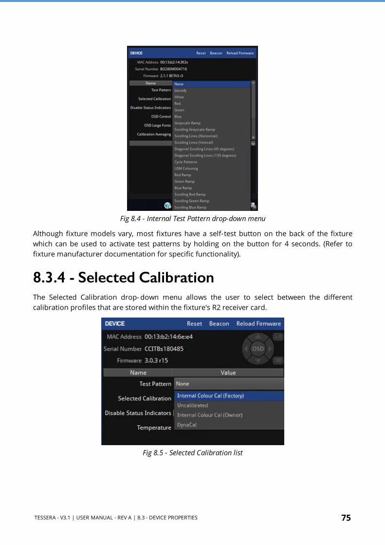
TESSERA - V3.1 | USER MANUAL - REV A | 8.3 - DEVICE PROPERTIES 75
Fig 8.4 - Internal Test Pattern drop-down menu
Although fixture models vary, most fixtures have a self-test button on the back of the fixture which can be used to activate test patterns by holding on the button for 4 seconds. (Refer to fixture manufacturer documentation for specific functionality).
8.3.4 - Selected CalibrationThe Selected Calibration drop- down menu allows the user to select between the different calibration profiles that are stored within the fixture's R2 receiver card.
Fig 8.5 - Selected Calibration list

76 TESSERA - V3.1 | USER MANUAL - REV A | 8.4 - OSD
8.3.5 - Disable Status IndicatorThe status indicator of the root nodes can be disabled if necessary, by toggling the tick box.
8.3.6 - Sensors InformationInformation from sensors such as temperature or humidity is displayed if available in the fixture.
8.4 - OSDOSD or On-Screen Display is supported on R2-based fixtures and offers the possibility to display information on the fixture itself, the processor or the project.
NOTE OSD is supported on rectangular fixtures with a minimum size of 64x64 pixels but no larger than 1024 pixels in either dimension and up to 262,000 pixels (e.g. 512x512, 1024x256, etc.)
RA-16 based fixtures are not supported
Fig 8.6 - OSD controls
To access OSD, click on or select multiple fixtures to reveal the Fixture properties editor.
Click on the OSD button to activate, click again to deactivate. To navigate OSD, use the left and right arrows to cycle through categories, and use the up and down arrows to cycle through pages within each category.
If viewing OSD from a distance, it can be useful to use enlarged fonts by pressing the size button next to the OSD buttons. To have this option available, the panels needs to be at least
128x128 pixels.
To trigger OSD from using the rear self-test button on the back of a fixture, press and release the button three times. OSD is only applicable to fixtures running firmware Tessera version 2.1 and above.

TESSERA - V3.1 | USER MANUAL - REV A | 8.5 - STUDIO MODE 77
8.5 - Studio modeStudio Mode reduces a fixture's maximum brightness while maintaining the PWM bit depth, thereby resulting in improved image quality (with less banding) when running at low brightness. The maximum benefit is seen on particularly bright fixtures, especially those running at relatively low PWM bit depth (14 bit or below). See Studio Mode on page 185 for more information.
For fixtures supporting this feature, Studio Mode can be enabled or disabled using the Studio Mode checkbox.
Below are some comparison images showing the advantages of Dark Magic and Studio Mode.
Normal (no Dark Magic or Studio Mode)
Banding clearly visible at the low end of the gradient
Dark Magic (only)
Banding eliminated, some slight 'sparkle' visible
Studio Mode (only)
Banding less pronounced, but still visible
Dark Magic and Studio Mode
No banding and reduced sparkle
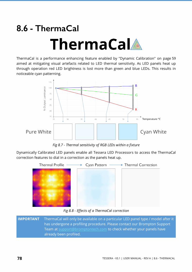
78 TESSERA - V3.1 | USER MANUAL - REV A | 8.6 - THERMACAL
8.6 - ThermaCal
ThermaCal is a performance enhancing feature enabled by "Dynamic Calibration" on page 59 aimed at mitigating visual artefacts related to LED thermal sensitivity. As LED panels heat up through operation red LED brightness is lost more than green and blue LEDs. This results in noticeable cyan patterning.
Fig 8.7 - Thermal sensitivity of RGB LEDs within a fixture
Dynamically Calibrated LED panels enable all Tessera LED Processors to access the ThermaCal correction features to dial in a correction as the panels heat up.
Fig 8.8 - Effects of a ThermaCal correction
IMPORTANT ThermaCal will only be available on a particular LED panel type / model after it has undergone a profiling procedure. Please contact our Brompton Support Team at [email protected] to check whether your panels have already been profiled.

TESSERA - V3.1 | USER MANUAL - REV A | 8.6 - THERMACAL 79
8.6.1 - Applying a ThermaCal CorrectionThermaCal is available on all Tessera LED Processor s that are paired with Dynamically Calibrated LED panels. Any ThermaCal correction is applied at the panel-level.
Fig 8.9 - ThermaCal controls within the Device Properties
Should cyan patterning occur, apply a ThermaCal correction by:
1. Selecting the problematic panels from the canvas. 2. Under the panel "Device Properties" on page 74 3. Dial in the ThermaCal Amount slider until the cyan patterning disappears.
Any ThermaCal correction made has to be dialled-in by eye as the slider is capable of going beyond the needed amount creating an overcorrection. Refer to "Recognising applied ThermaCal under and over corrections" below to help recognise a ThermaCal over correction.
Fig 8.10 - Recognising applied ThermaCal under and over corrections

80 TESSERA - V3.1 | USER MANUAL - REV A | 8.7 - FIXTURE CONTEXT MENU
8.7 - Fixture Context MenuRight-click a fixture to open a context menu with a list of options. These options are grouped by type and some options have keyboard shortcuts displayed on the right side column. If a fixture is un-associated, some options are unavailable.
Fig 8.11 - Fixture context menu options

TESSERA - V3.1 | USER MANUAL - REV A | 8.7 - FIXTURE CONTEXT MENU 81
Function Description
Copy Copy the fixture
Paste
Paste the fixture in the canvas
The rotation value is also added but other values such as the modifications in the fixture Colour property editor (see Fixture Properties on page 71) are not copied into the new fixture.
GroupMake a group with the selected fixture/fixtures.
Grouping fixtures is necessary to create presets or to control fixtures properties via DMX or eDMX protocols.
UngroupBreak the selected group/groups. Please note that ungrouping deletes the group information (name, colour, etc) and movement records of the selected group in all relevant presets.
Remove from groupRemoves the selected fixture from a group without breaking the group.
To select one or several fixtures from a group, hold the Shift key while selecting the fixture/fixtures.
ReorientRotates square fixtures around their own axis by 90° and rectangular fixtures by 180°
Rotate selection Rotate the selected fixtures around the selection’s axis
Select string Select all the fixtures connected to the same string as the one selected
Send to backSend to the back of the z-axis of the selected layer.
Please note that, above the z-axis order in a layer, the order of layers determine which fixtures can be seen on top
Move to layer Move the selection to a layer
Disassociate Remove the association of the selected fixture
Correct association Fix the topology re-associating fixtures
Zoom to selection Fits the canvas zoom to display the selected fixture / fixtures
Snap active area to selection
Applies the scaler to fit the active area to the selected fixtures
Delete Delete the selected fixture / fixtures

82 TESSERA - V3.1 | USER MANUAL - REV A | 8.8 - ADDING FIXTURES TO A PROJECT
8.8 - Adding Fixtures to a ProjectThere are two main workflows for adding fixtures to a project.
l With fixtures connected to the processor. The project and fixture layout are created on a processor with fixtures physically connected. In this case use Add Fixtures from Network
l Without fixtures connected to the processor (or in offline mode). Alternatively, if a fixture is not connected, select Add Fixture from Library which accesses the fixture library displaying all fixtures installed from Fixture Pack s that are currently installed on the processor. Navigate or use the search function to find the fixture required and add it to the canvas.
See Fixture Library on page 240 for more information.
Users can use whichever workflow is most convenient for their project, including a combination of the two.
8.9 - Add Fixtures from NetworkOn the toolbar above the canvas space, a circular indicator on the Add Fixtures from Network
button is greyed out if fixtures are not detected or not connected to the processor. This feature is not accessible until fixtures are physically connected and detected by the processor. Once detected, the indicator turns green.
After clicking Add Fixtures from Network, the toolbar displays detected fixtures and strings of fixtures grouped by output ports. A string is a continuous daisy-chain of Tessera compatible fixtures.
8.9.1 - Associating FixturesThere are two ways to associate fixtures:
Quick AssociationWhen fixtures are connected to the processor, each string is assigned a unique numeric code. Entering the code on the processor (using number keys or numpad) selects the corresponding string, the string then has the first fixture attached to the cursor for placement on the canvas.

TESSERA - V3.1 | USER MANUAL - REV A | 8.9 - ADD FIXTURES FROM NETWORK 83
Fig 8.12 - Left: numeric values corresponding to the fixture when entering Associate Fixtures from Network. Right: when a numerical value has been entered in the processor
NOTE This feature is only supported by Tessera R2-based fixtures with at least 64x64 pixels.
When the processor recognizes more than 9 strings attached, string numbers have more than one digit, therefore strings must be entered with the same number of digits as the number of the last string detected e.g. 01 or 005.
Fig 8.13 - Use the keyboard to enter the shown number on fixture string to add to canvas
Mouse Selection AssociationAssociating fixtures can also be done by selecting the port. All fixtures connected to each port are highlighted with the same colour. For example, on a Tessera M2 LED Processor, the fixtures on output 1 are always highlighted in red. Similarly, when selecting a port on a root node, the ports is always highlighted in the same colour such as port 1 is always red.
Fig 8.14 - Click on either port A or B to associate to canvas
Fig 8.15 - Tessera SX40 with Tessera XD Units, select one to associate to canvas

84 TESSERA - V3.1 | USER MANUAL - REV A | 8.9 - ADD FIXTURES FROM NETWORK
When associating by selecting ports for each string, the string is represented by a unique colour in the user interface and physical fixtures. Fixtures illuminate corresponding to identified strings.
l The Tessera T1 LED Processor only has a single output port so there is no port selection and only displays available strings of fixtures.
l For the Tessera SX40 LED Processor, the user needs to first select the trunk where the Tessera XD is connected before continuing to ports compared to other processors.
l During fixture association, if the string contains multiple types of fixtures they are illustrated in the user interface, and the current part of the string is highlighted.
Blind ModeBlind association is available to associate fixtures while panels remain off. This feature can be toggled on/off in Add Fixtures from Network view. To enter this mode with fixtures always off, hold the Alt button when clicking on Add fixtures from network .
RotationFixtures can be rotated before being placed on the canvas. Use the Rotation slider on the Draw Array property editor or alternatively use Alt + mouse wheel to modify the rotation angle.
Fig 8.16 - Draw array feature for rotating fixtures before placing
Array TypesTo place an array of fixtures, hold the left mouse button while placing the fixture. The array is direction sensitive and topology changes depending which direction the mouse is dragged.
Topology can be adjusted or re-assigned later from the Canvas view using the Topology tool.
Once an array is created, the Add Fixtures property editor is shown with the following options:
Group FixturesGroups the array that the user has created.
For Tessera M2 and T1 LED Processors, there are 3 types of array layouts: Grid, Circle and Radial.
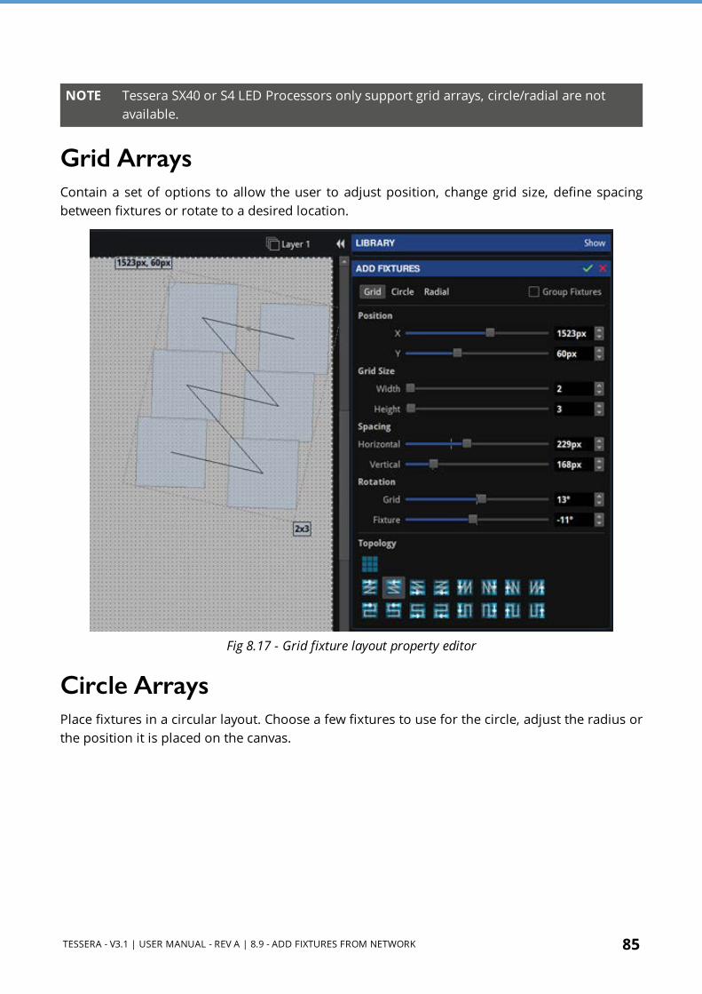
TESSERA - V3.1 | USER MANUAL - REV A | 8.9 - ADD FIXTURES FROM NETWORK 85
NOTE Tessera SX40 or S4 LED Processors only support grid arrays, circle/radial are not available.
Grid ArraysContain a set of options to allow the user to adjust position, change grid size, define spacing between fixtures or rotate to a desired location.
Fig 8.17 - Grid fixture layout property editor
Circle ArraysPlace fixtures in a circular layout. Choose a few fixtures to use for the circle, adjust the radius or the position it is placed on the canvas.
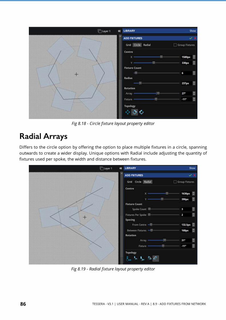
86 TESSERA - V3.1 | USER MANUAL - REV A | 8.9 - ADD FIXTURES FROM NETWORK
Fig 8.18 - Circle fixture layout property editor
Radial ArraysDiffers to the circle option by offering the option to place multiple fixtures in a circle, spanning outwards to create a wider display. Unique options with Radial include adjusting the quantity of fixtures used per spoke, the width and distance between fixtures.
Fig 8.19 - Radial fixture layout property editor

TESSERA - V3.1 | USER MANUAL - REV A | 8.10 - ADD FIXTURES FROM LIBRARY 87
8.10 - Add Fixtures from LibraryIt is possible to work offline and create a layout when fixtures are not connected to the processor in one of two ways. Tessera Offline Editor in Tessera Remote or the local user interface, in each case the user will need to add fixtures from library as no fixtures are connected and nothing will appear in the add fixtures from network window.
Add Fixtures from Library displays the Fixture Library and Draw Array Fixture editor, allowing the user to draw fixtures to your project’s utilizing the installed Fixture Packs available on the processor or on Tessera Remote.
Fig 8.20 - Fixture library with list of installed fixture firmware on the processor
The Search bar can be used to filter the list or find a specific fixture. To only display fixtures that are already placed on the canvas, select Used in the top-right corner. Similarly, to only show connected fixtures click Online to reduce the list to fixtures types that are connected to the processor.
Select a fixture from the list and click on the canvas to add the fixture.
8.11 - Assigning or Modifying Online Fixture TopologyTo associate a fixture already placed on the canvas:
Click the relevant fixture on the canvas.
1. If the fixtures on the canvas already have topology applied, the user is prompted to associate the rest of the string using the highlighted red string. Press enter to
88 TESSERA - V3.1 | USER MANUAL - REV A | 8.11 - ASSIGNING OR MODIFYING ONLINE FIXTURE TOPOLOGY
associate the fixture to the string. 2. If only part of the string is required, hold the Shift key and select the last fixture to
associate. 3. Alternatively, continue to associate fixtures individually by clicking each fixture on
the canvas in turn.
If the user creates a new topology for panels which have already been associated, the old topology will be discarded in favour of the new topology/association.
See Understanding Topology and Association on page 97 for more information.

TESSERA - V3.1 | USER MANUAL - REV A | 8.12 - SUB-FIXTURES 89
8.12 - Sub-FixturesSub-fixtures do not have a Tessera interface and so cannot be connected directly to a Processor or XD output. Instead multiple fixtures are connected to a single power/control box. These fixtures are represented in the Tessera system as sub-fixtures. The power/control boxes are called root nodes.
Each root node contains a R2 receiver card, and like normal panel-type fixtures are connected to the rest of the system over daisy-chained Gigabit Ethernet. Root nodes connect to sub-fixtures using a proprietary data/power connection.
Tessera SX40 processor includes support for sub- fixtures from firmware version 2.3 and upwards, similar to Brompton's HD processors, a maximum of 2000 fixtures, sub-fixtures or a combination of both can be used per processor.
Fig 8.21 - Sub-fixtures being used with conventional LED panels
NOTE When calculating processor pixel capacity, sub-fixtures with less than 64 pixels are calculated as the same as 100 pixels.
NOTE As on other processors, the fixture limit on Tessera SX40 also applies to sub-fixtures. (I.e. 2000 fixtures, sub-fixtures, or a combination of the two.) Sub-fixtures which are smaller than 64 pixels in one or both dimensions have these dimensions rounded up to 64 when calculating the processor load. (I.e. A 1 x 100 pixel sub-fixture has the same load as a 64 x 100 pixel panel.)
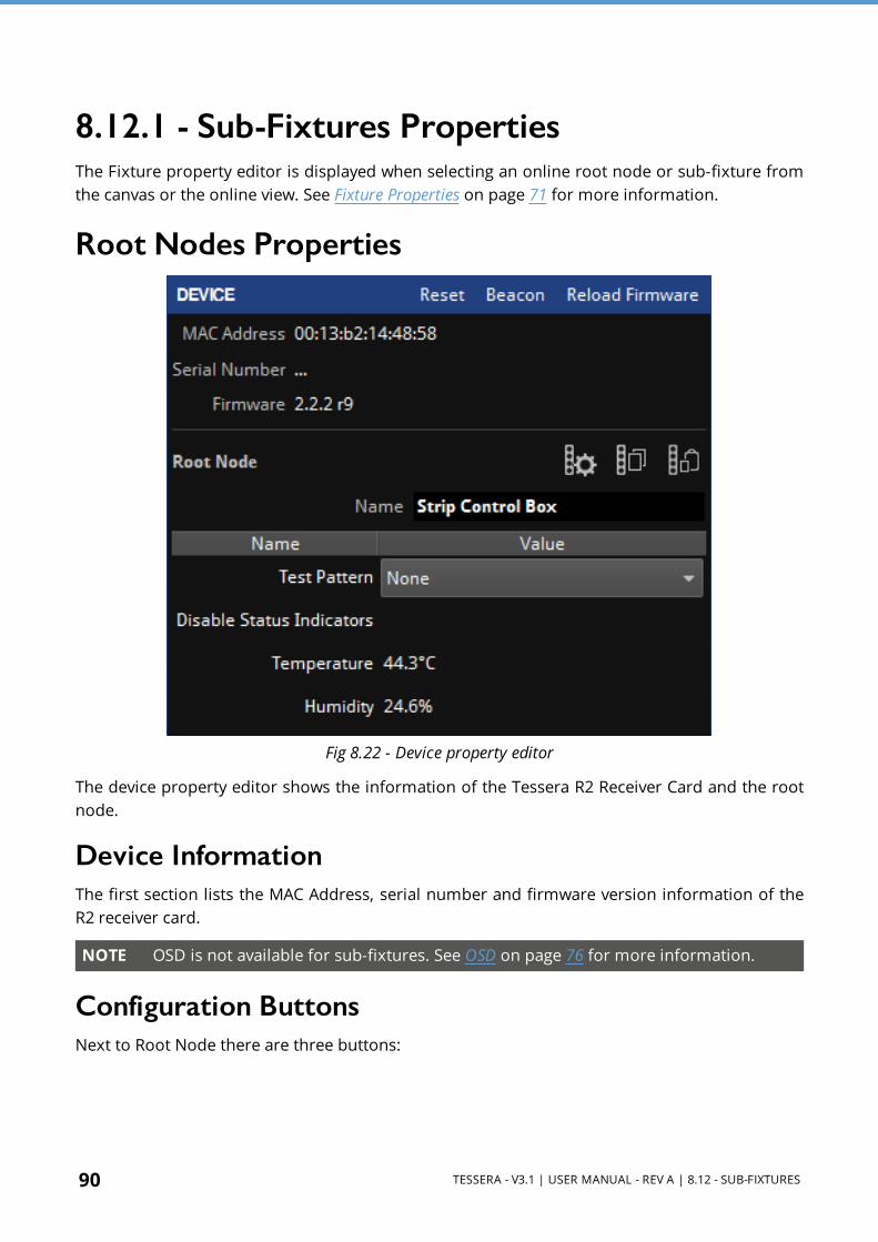
90 TESSERA - V3.1 | USER MANUAL - REV A | 8.12 - SUB-FIXTURES
8.12.1 - Sub-Fixtures PropertiesThe Fixture property editor is displayed when selecting an online root node or sub-fixture from the canvas or the online view. See Fixture Properties on page 71 for more information.
Root Nodes Properties
Fig 8.22 - Device property editor
The device property editor shows the information of the Tessera R2 Receiver Card and the root node.
Device InformationThe first section lists the MAC Address, serial number and firmware version information of the R2 receiver card.
NOTE OSD is not available for sub-fixtures. See OSD on page 76 for more information.
Configuration ButtonsNext to Root Node there are three buttons:

TESSERA - V3.1 | USER MANUAL - REV A | 8.12 - SUB-FIXTURES 91
l Configure root node Allows the user to specify sub-fixtures on each port. See Configuring the Root Nodes Online on page 93 for more information.
l Copy root node configuration Copy the configuration for the selected root node.
l Paste root node configuration Paste the copied configuration for the selected root node.
Using Copy/Paste can make the workflow quicker when using larger amounts of root nodes. Several root nodes can be selected, and the configuration pasted to all of them at the same time.
Test PatternThe Test Pattern drop-down menu allows you to select a range of internal test patterns that are generated on the fixtures R2 receiver card. The patterns can be displayed on all connected sub-fixtures whether they are associated to the processor. See Sub-Fixture Internal Test Patterns on page 96 for more information.
Disable Status IndicatorThe status indicator of the root nodes can be disabled by toggling the tick box.
Sensors InformationInformation such as Temperature or Humidity is displayed if the root node has the appropriate sensors.
8.12.2 - Sub-Fixtures Context MenuRight-click in a root node to open a context menu with a list of options. Sub-fixture options are the same as other fixture’s options. Root nodes have additional functions to “Configure” (only when the root node is online) and “Add Sub-fixtures” options for the addition of sub-fixtures and root node configuration.
Fig 8.23 - Extra option for sub-fixtures in context menu

92 TESSERA - V3.1 | USER MANUAL - REV A | 8.12 - SUB-FIXTURES
8.12.3 - Associating Sub-FixturesSub-fixtures may be individually positioned and rotated on the canvas, just like normal fixtures. Root nodes are not typically able to detect what types and quantities of sub- fixtures are connected to their outputs and must be assigned by the processor. Root nodes can be added to the canvas using the Add Fixtures from Library or Add Fixtures from Network tools.
Adding Sub-Fixtures Online or Offline Using Add Fixtures from Library or Add Fixtures from Network
1. Click Add Fixtures from Library or Add Fixtures from Network 2. Select the root node and place it on the canvas. 3. Press Enter to return to the Canvas view. 4. Right-click in the root node and select Add Sub-fixtures. 5. Repeated presses of Tab or the Next Port button advances through the ports, before
returning to adding root nodes. 6. The type of fixture can be selected from the Library list. Select the relevant sub-fixtures
and add them to the canvas.
Fig 8.24 - Adding a sub-fixture to canvas
7. Repeat steps 3 and 4 until all fixtures are placed. 8. Press Enter or Escape to confirm the association 9. If the Configure root nodes error appears. Click the button to confirm topologies and root
node configuration.
Fig 8.25 - Notification to configure root nodes not matching fixture topology

TESSERA - V3.1 | USER MANUAL - REV A | 8.12 - SUB-FIXTURES 93
Configuring the Root Nodes OnlineUsing Add Fixtures from Network . The root nodes need to be connected to the processor and online.
1. Click Add Fixtures from Library or Add Fixtures from Network 2. Select your root node and place it on the canvas. 3. Press Enter to return to Canvas view. 4. Right-click in the root node and select Configure. A new window opens with the root node
configuration options.
Fig 8.26 - Strip control box configuration menu
5. The control box stores the last configuration from previous projects. To delete all associated sub-fixtures click Clear all ports or to delete individual sub-fixtures, select and press the delete button.
6. Select the port, sub-fixture type and the number of sub-fixtures then click Add devices. This may take a couple of seconds for the root node to configure.
Once configured, sub- fixtures can be added. If the topology differs from the root node configuration, root nodes can be reconfigured by pressing the Configure Root Nodes button in the error message.
Fig 8.27 - Notification to configure root nodes not matching fixture topology

94 TESSERA - V3.1 | USER MANUAL - REV A | 8.12 - SUB-FIXTURES
OfflineUsing Add Fixtures from Library
1. Click Add Fixtures from Library. 2. Select the root nodes and place on the canvas. The search bar can be used to filter
fixtures.
Fig 8.28 - Adding a Root node to canvas
3. Press Tab to start associating sub- fixtures. Repeated presses of Tab or the Next Port button advances through the ports.
4. The type of fixture can be selected from the Library menu. Select the sub-fixtures and add them to the canvas.
Fig 8.29 - Adding a sub-fixture to canvas
5. Repeat steps 3 and 4 until all your fixtures are placed. 6. Press Enter or Escape to confirm the association.
Once fixtures are connected to the processor, the root nodes can be associated. Strings of root nodes appear the same as strings of normal fixtures in the Add Fixtures From Network tool. See Adding Fixtures to a Project on page 82 for more information.
When a root node is associated, its outputs is automatically reconfigured with the correct types of sub-fixtures drawn in the topology, and sub-fixtures are automatically associated.
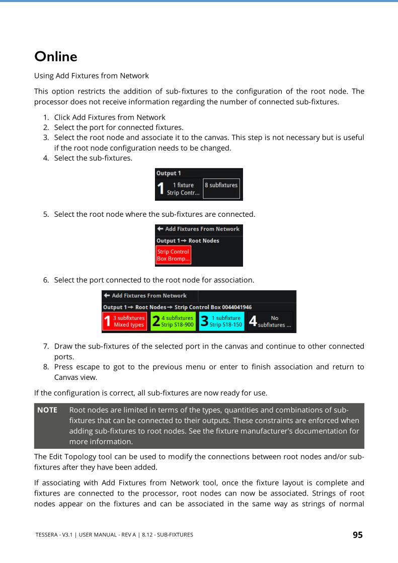
TESSERA - V3.1 | USER MANUAL - REV A | 8.12 - SUB-FIXTURES 95
OnlineUsing Add Fixtures from Network
This option restricts the addition of sub- fixtures to the configuration of the root node. The processor does not receive information regarding the number of connected sub-fixtures.
1. Click Add Fixtures from Network 2. Select the port for connected fixtures. 3. Select the root node and associate it to the canvas. This step is not necessary but is useful
if the root node configuration needs to be changed. 4. Select the sub-fixtures.
5. Select the root node where the sub-fixtures are connected.
6. Select the port connected to the root node for association.
7. Draw the sub-fixtures of the selected port in the canvas and continue to other connected ports.
8. Press escape to got to the previous menu or enter to finish association and return to Canvas view.
If the configuration is correct, all sub-fixtures are now ready for use.
NOTE Root nodes are limited in terms of the types, quantities and combinations of sub-fixtures that can be connected to their outputs. These constraints are enforced when adding sub-fixtures to root nodes. See the fixture manufacturer's documentation for more information.
The Edit Topology tool can be used to modify the connections between root nodes and/or sub-fixtures after they have been added.
If associating with Add Fixtures from Network tool, once the fixture layout is complete and fixtures are connected to the processor, root nodes can now be associated. Strings of root nodes appear on the fixtures and can be associated in the same way as strings of normal
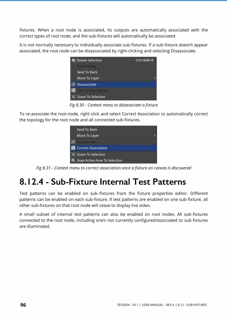
96 TESSERA - V3.1 | USER MANUAL - REV A | 8.12 - SUB-FIXTURES
fixtures. When a root node is associated, its outputs are automatically associated with the correct types of root node, and the sub-fixtures will automatically be associated.
It is not normally necessary to individually associate sub-fixtures. If a sub-fixture doesn’t appear associated, the root node can be disassociated by right-clicking and selecting Disassociate.
Fig 8.30 - Context menu to disassociate a fixture
To re-associate the root-node, right click and select Correct Association to automatically correct the topology for the root node and all connected sub-fixtures.
Fig 8.31 - Context menu to correct association once a fixture on canvas is discovered
8.12.4 - Sub-Fixture Internal Test PatternsTest patterns can be enabled on sub- fixtures from the fixture properties editor. Different patterns can be enabled on each sub-fixture. If test patterns are enabled on one sub-fixture, all other sub-fixtures on that root node will cease to display live video.
A small subset of internal test patterns can also be enabled on root nodes. All sub-fixtures connected to the root node, including one’s not currently configured/associated to sub-fixtures are illuminated.

TESSERA - V3.1 | USER MANUAL - REV A | 8.13 - UNDERSTANDING TOPOLOGY AND ASSOCIATION 97
8.13 - Understanding Topology and AssociationTessera LED Processors can detect the topology of connected fixtures. Topology is the order which fixtures are connected, which port on the processor they are connected to and if fixtures are broken into strings by switches. The topology tools are used to help users associate physical fixtures with fixtures on the canvas.
Fixtures are identified by a unique MAC address. When a physical fixture is associated in the project, the MAC address is recorded, and association persists until the user makes changes.
If the real-world topology is changed after fixtures are associated, For example; a video wall is re-cabled, the fixture association is not automatically re-configured by the processor. Turn on Show Topology Errors in Canvas Properties (right-click on canvas) or in the View dropdown menu to highlight in red any changes found on the canvas.
Fig 8.32 - Example of incorrect topology, notice the arrows on the far left and right are highlighted in red
8.13.1 - Swapping Fixtures and Correcting AssociationEach fixture connected to a Tessera LED Processor is recognised as a unique fixture. Each unique fixture is associated with a position on the canvas. If a fixture goes offline or is removed, the fixture remains on the canvas but is now disassociated. The status dot on the Add fixtures

98 TESSERA - V3.1 | USER MANUAL - REV A | 8.13 - UNDERSTANDING TOPOLOGY AND ASSOCIATION
from network button , which usually has a green status indicator when the fixture is online, will now turn grey.
In instances where a fixture is swapped out from the string, the processor will detect a disappearance and a new fixture will appear in the same position. The processor will detect a swap-out has taken place and will offer the user the option to perform Correct Association.
To Perform a Swap-Out of One Fixture 1. Disconnect and remove the fixture. 2. Insert and connect a new fixture into the same position of the string. The processor
prompts the user with the following message:
Fig 8.33 - The correct association dialog box
3. This message is available for 10 seconds. After this message expires, the Correct Association option can be found by right-clicking on the icon of the affected fixture or by selecting Correct Association from the Edit dropdown menu or edit topology toolbar .

TESSERA - V3.1 | USER MANUAL - REV A | 8.13 - UNDERSTANDING TOPOLOGY AND ASSOCIATION 99
Changing Physical TopologyIf the fixtures’ topology is modified, for example to balance the ports load, the fixtures are automatically re-associated.
Example: The fixtures in a wall are associated to the processor in a topology using ports 1 and 2 as shown below:
Fig 8.34 - Fixtures associated to the processor using ports 1 and 2
Fig 8.35 - Fixtures with topology changed to balance laod on ports
Due to the port capacity restrictions, the topology of some fixtures need to be changed from port 1 to port 2 to balance the load on ports.
The processor automatically recognizes the fixtures MAC addresses and re- associates this fixture in the project. To see the topology errors, enable Show Topology Errors in the canvas index menu. The fixtures automatically begin functioning at this stage.
The processor may prompt the following message:
Fig 8.36 - The correct association dialog box
Confirm by pressing the Correct Association button .

100 TESSERA - V3.1 | USER MANUAL - REV A | 8.13 - UNDERSTANDING TOPOLOGY AND ASSOCIATION
The Correct Association option can be also done by selecting Correct Association from the Edit dropdown menu or in the Edit topology toolbar menu .
Pressing the correct association button repairs the canvas topology.
Changing Canvas TopologyThe topology can be manually changed using the topology toolbar that appears when pressing the Edit Topology button.
Fig 8.37 - Topology view options
As an example, if the fixtures were first cabled in a continuous string from left to right and from bottom to top as viewed from the front of the screen.
Fig 8.38 - First topology
The second time the fixtures are connected, the cabling topology is changed, as shown below.
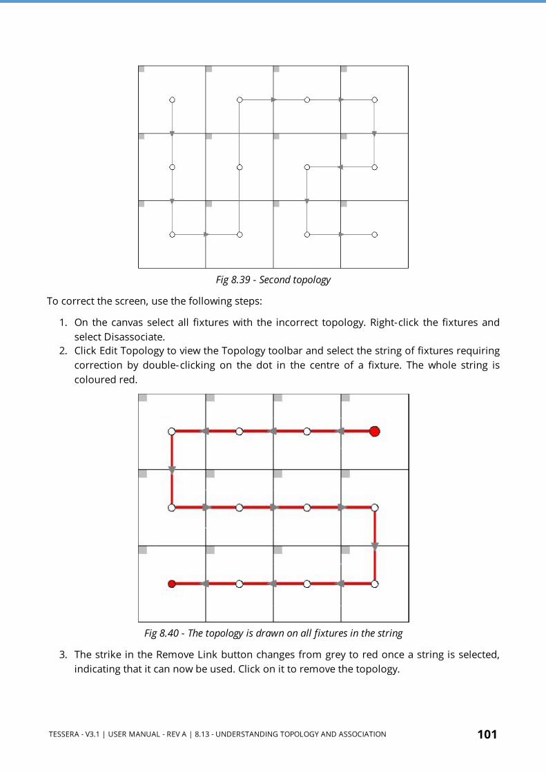
TESSERA - V3.1 | USER MANUAL - REV A | 8.13 - UNDERSTANDING TOPOLOGY AND ASSOCIATION 101
Fig 8.39 - Second topology
To correct the screen, use the following steps:
1. On the canvas select all fixtures with the incorrect topology. Right-click the fixtures and select Disassociate.
2. Click Edit Topology to view the Topology toolbar and select the string of fixtures requiring correction by double-clicking on the dot in the centre of a fixture. The whole string is coloured red.
Fig 8.40 - The topology is drawn on all fixtures in the string
3. The strike in the Remove Link button changes from grey to red once a string is selected, indicating that it can now be used. Click on it to remove the topology.

102 TESSERA - V3.1 | USER MANUAL - REV A | 8.13 - UNDERSTANDING TOPOLOGY AND ASSOCIATION
4. Hover the mouse over the centre spot of the fixture which is to be at the start of the string. Click and drag the pointer to the centre spot of the second fixture on the string. A dotted red line is drawn which turns solid as the line becomes pinned to the centre spot of the next fixture in the string.
5. Repeat the process until the string is complete.
Fig 8.41 - Re-applying the string
6. The topology direction can be reversed by clicking Reverse topology when a string is highlighted.
Fig 8.42 - Completed topology string

TESSERA - V3.1 | USER MANUAL - REV A | 8.13 - UNDERSTANDING TOPOLOGY AND ASSOCIATION 103
7. Once corrections are complete, return to the main project view by pressing Esc or clicking on the arrow located at the top left of the interface . The processor detects a new topology which doesn’t match the current association and displays the Correct Association message for 10 seconds.
Fig 8.43 - The incorrect topology notification
8. Click the Correct Association button to finish the process. The fixture icons display a green indicator when associated to the canvas. Source content can be displayed on associated fixtures.
Fig 8.44 - The fixtures are online and associated.
Alternatively, the string can be associated using Add Fixtures from Network. See Associating Fixtures on page 82 for more information.

104 TESSERA - V3.1 | USER MANUAL - REV A | 8.14 - FIXTURE LAYOUT
8.14 - Fixture Layout
8.14.1 - Selecting Individual FixturesClick to select a fixture. The fixture will turn blue and the Fixture property editor will be displayed on the right side of the user interface. See Fixture Properties on page 71 for more information. Right-click on a fixture to display a context menu. See Fixture Context Menu on page 80 for more information.
8.14.2 - Selecting Multiple FixturesThere are various methods to select multiple fixtures:
l Ctrl + left-click on fixtures to individually select them. l Hold the left mouse button and drag to create a selection box around the fixtures, release
button to finish selecting. For more information about selection modes. See Selection Mode on page 246 for more information.
l To select all fixtures on the canvas, use Ctrl + A, or ⌘ + A on Mac OSX.
8.14.3 - Grouping FixturesA selection of fixtures can be combined into a group. When changes are made with the group selected, such as moving or adjusting colour, the fixtures contained within the group always change together. This feature saves time by not having to configure fixtures separately and improves accuracy by moving a wall of fixtures making sure that the relative position of the fixtures don’t change.
NOTE The maximum possible number of groups on any project is 200.
To set a group, select the required fixtures, right-click and choose Group from the dropdown menu, the same method is used to ungroup fixtures. Use Ctrl+G to group fixtures or Ctrl+Shift+G to ungroup fixtures.
To select one or several fixtures from a group, hold the Shift key while selecting the fixture/fixtures. These fixtures remain in the group while being modified, without breaking the group.
NOTE If a group is broken by ungrouping or removing fixtures, all relevant presets where the group has a recorded position will also be updated/deleted accordingly. The following warning is displayed: “Any colour overrides associated with that group will be lost”.

TESSERA - V3.1 | USER MANUAL - REV A | 8.14 - FIXTURE LAYOUT 105
Group Properties The Group property editor appears when a group is selected. It is composed of Group and Colour.
Fig 8.45 - Group properties
Group
The group property editor is divided in three sections.
Group info
l Name: Change the name of the group. l To see the name in the canvas, activate Show Group Names in the View dropdown menu
or in the Canvas context menu. See Canvas Context Menu on page 113 for more information.
l Colour: Click in the colour box to select a different colour from the palette.

106 TESSERA - V3.1 | USER MANUAL - REV A | 8.14 - FIXTURE LAYOUT
Position
The second section of this property editor displays the position and rotation of the fixture in the canvas. Changes can be locked to avoid modifications. Modifications can be done by typing or using the spin box arrows. The Reorient button rotates the fixture by 90 degrees clockwise for square fixtures, or 180 degrees for rectangular fixtures.
Rotation centre
The rotation centre of the group can be modified. The canvas coordinates for the centre can be typed or selected in the spin boxes. Alternatively, choose one of the Snap To options to place it in the predefined positions of the group.
Colour
Colour modifications can be enabled in the selected fixture independently from the Global Colour. When the Override Global Colour box is ticked, colour modifications for the selected fixture are enabled and Global Colour property editor values do not have an effect on the fixture.
Group Context MenuRight-click in a group to open a context menu with a list of options. Group options are a small selection of the Fixture options. With the addition of the Select Grouped Fixtures option to ease the selection of the fixtures contained in the group instead of the group itself.
Fig 8.46 - Context menu when selecting a group, there is an option to ungroup
Select one or several fixtures from a group by pressing the Shift key while selecting the fixture/fixtures. These fixtures remain in the group while being modified, without ungrouping.
8.14.4 - Moving FixturesFixtures can be moved anywhere on the Canvas, either within or outside of the Active Area by selecting the fixture and dragging with a mouse or pressing arrow keys on the keyboard. Pressing the arrow keys will move the fixture by grid- space increments. The grid space increment size can be modified in the Canvas properties dropdown menu. See Canvas Properties on page 110 for more information.
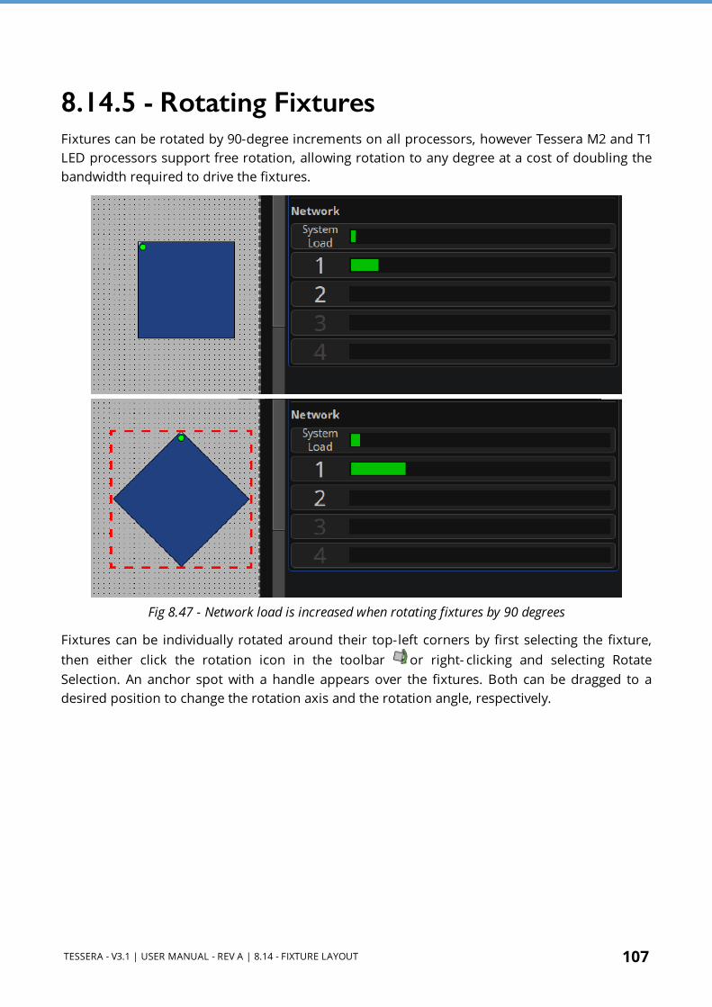
TESSERA - V3.1 | USER MANUAL - REV A | 8.14 - FIXTURE LAYOUT 107
8.14.5 - Rotating FixturesFixtures can be rotated by 90-degree increments on all processors, however Tessera M2 and T1 LED processors support free rotation, allowing rotation to any degree at a cost of doubling the bandwidth required to drive the fixtures.
Fig 8.47 - Network load is increased when rotating fixtures by 90 degrees
Fixtures can be individually rotated around their top-left corners by first selecting the fixture, then either click the rotation icon in the toolbar or right- clicking and selecting Rotate Selection. An anchor spot with a handle appears over the fixtures. Both can be dragged to a desired position to change the rotation axis and the rotation angle, respectively.
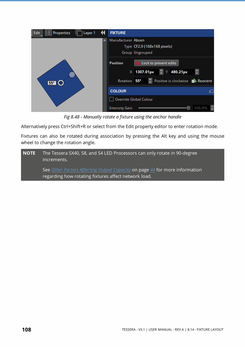
108 TESSERA - V3.1 | USER MANUAL - REV A | 8.14 - FIXTURE LAYOUT
Fig 8.48 - Manually rotate a fixture using the anchor handle
Alternatively press Ctrl+Shift+R or select from the Edit property editor to enter rotation mode.
Fixtures can also be rotated during association by pressing the Alt key and using the mouse wheel to change the rotation angle.
NOTE The Tessera SX40, S8, and S4 LED Processors can only rotate in 90-degree increments.
See Other Factors Affecting Output Capacity on page 44 for more information regarding how rotating fixtures affect network load.
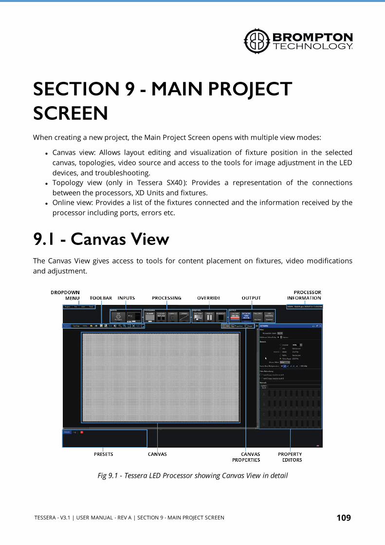
TESSERA - V3.1 | USER MANUAL - REV A | SECTION 9 - MAIN PROJECT SCREEN 109
SECTION 9 - MAIN PROJECT SCREENWhen creating a new project, the Main Project Screen opens with multiple view modes:
l Canvas view: Allows layout editing and visualization of fixture position in the selected canvas, topologies, video source and access to the tools for image adjustment in the LED devices, and troubleshooting.
l Topology view (only in Tessera SX40 ): Provides a representation of the connections between the processors, XD Units and fixtures.
l Online view: Provides a list of the fixtures connected and the information received by the processor including ports, errors etc.
9.1 - Canvas ViewThe Canvas View gives access to tools for content placement on fixtures, video modifications and adjustment.
Fig 9.1 - Tessera LED Processor showing Canvas View in detail

110 TESSERA - V3.1 | USER MANUAL - REV A | 9.1 - CANVAS VIEW
9.1.1 - Canvas PropertiesThe canvas properties editor can be accessed by selecting Properties in the canvas properties toolbar, on the top-right of the canvas.
Fig 9.2 - Canvas properties
SizeThe canvas size can be freely modified however the input source must fit within the width and height dimensions. Depending on the selected resolution, some limitations might apply. See Canvas Resolutions on page 65 for more information.
Pixel PitchThis option only appears when fixtures with two different pixel pitches are drawn in the canvas. Clicking the check-box alternates between 1:1 and interpolated modes. See Mapping Options on page 68 for more information.
UnitsSelect between millimetres, inches or pixels for the background modifications.

TESSERA - V3.1 | USER MANUAL - REV A | 9.1 - CANVAS VIEW 111
9.1.2 - Background
ShowToggle to enable or disable the background view. Click Browse to navigate to a image file. JPG or PNG files are compatible.
FileSelect Browse to select a file from the USB drive or computer (when in Remote mode) to display in the background on the canvas. By default, the image aligns to the top-left of the canvas.
ClearDeletes the assigned background.
ScaleIf the image size differs to the canvas size or to the desired size, the size can be modified by selecting a pixel ratio. When the selected units are pixels, a 1px value will show the real size of the image, values lower than 1px reduces the image size while values above increase its size.
Press edit to click and drag a line on the background image and specify the final length that it should take in the canvas. The limit of this value is 1000px.
X/YAdjust the position of the top-left corner on the background image.
9.1.3 - Grid
ColourIf desired, the grid dots colour can be modified. This can be useful when using a background with an identical colour, to be able to differentiate the grid dots.
SpacingDefine the grid space in pixels. This value also modifies the number of pixels that a fixture is moved when using the keyboard arrows to move it around the canvas.
112 TESSERA - V3.1 | USER MANUAL - REV A | 9.1 - CANVAS VIEW
Canvas Edits EnabledEnables or disables modifiying the active area size or position of the canvas. This can be done by clicking the edges of the canvas and dragging to resize it.
See Active Area on page 164 for more information.
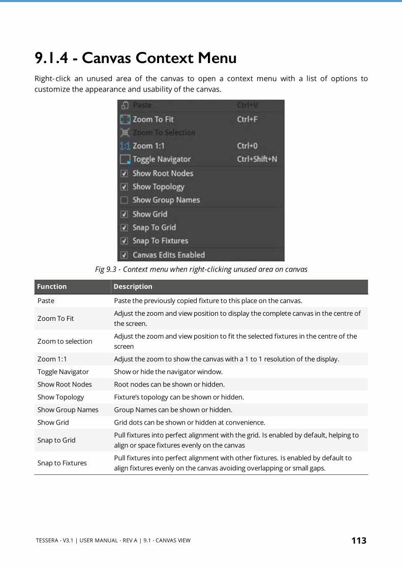
TESSERA - V3.1 | USER MANUAL - REV A | 9.1 - CANVAS VIEW 113
9.1.4 - Canvas Context MenuRight-click an unused area of the canvas to open a context menu with a list of options to customize the appearance and usability of the canvas.
Fig 9.3 - Context menu when right-clicking unused area on canvas
Function Description
Paste Paste the previously copied fixture to this place on the canvas.
Zoom To FitAdjust the zoom and view position to display the complete canvas in the centre of the screen.
Zoom to selectionAdjust the zoom and view position to fit the selected fixtures in the centre of the screen
Zoom 1:1 Adjust the zoom to show the canvas with a 1 to 1 resolution of the display.
Toggle Navigator Show or hide the navigator window.
Show Root Nodes Root nodes can be shown or hidden.
Show Topology Fixture’s topology can be shown or hidden.
Show Group Names Group Names can be shown or hidden.
Show Grid Grid dots can be shown or hidden at convenience.
Snap to GridPull fixtures into perfect alignment with the grid. Is enabled by default, helping to align or space fixtures evenly on the canvas
Snap to FixturesPull fixtures into perfect alignment with other fixtures. Is enabled by default to align fixtures evenly on the canvas avoiding overlapping or small gaps.

114 TESSERA - V3.1 | USER MANUAL - REV A | 9.1 - CANVAS VIEW
9.1.5 - Canvas ToolbarThe Main Toolbar offers a selection of tools to draw fixtures on the canvas and select zoom and view positions.
Fig 9.4 - Canvas toolbar features
Icon Icon Description Description
Undo/Redo arrowsUndo and redo the last action performed. The shortcut commands for Undo is Ctrl+Z (⌘+Z) and Redo with Ctrl+Shift+Z or Ctrl+Y
Add Fixtures from Library
Access to a menu with all the fixtures included in the Fixture Packs currently added to the processor. Once connected, these fixtures require associating. See Adding Fixtures to a Project on page 82 for more information.
Add Fixtures from Network
This button does not appear in the offline mode and is greyed out if there are no fixtures connected to the processor. Gives access to a menu for associating physically connected fixtures. See Adding Fixtures to a Project on page 82 for more information.
Edit TopologyModify and correct the topology connections between fixtures already added.
Free Rotation of Selected Fixtures
After clicking, an anchor spot with a handle appears over the fixtures. Both can be dragged to a desired position to change the rotation axis and the rotation angle, respectively. See Rotating Fixtures on page 107 for more information.
Zoom In and Zoom Out To adjust the view of canvas to appear larger or smaller.
Zoom To FitAdjust the zoom and view position to display the full size of the canvas in the centre of the screen.
Zoom To SelectionAdjust the zoom and view position to fit the selected fixtures in the centre of the screen.
Zoom 1:1 Adjust the zoom to show the canvas with a 1 to 1 resolution of the
Toggle Navigator Show or hide the navigator window.

TESSERA - V3.1 | USER MANUAL - REV A | 9.1 - CANVAS VIEW 115
9.1.6 - CANVAS Edit Views
Edit ModeEdit Mode views allow fixtures to be positioned on the canvas.
Edit Mode:
Keyboard Shortcut: F1
Edit Mode is the default mode for the canvas and allows fixture positioning. In Edit mode the fixtures are displayed as viewed from the front.
Rear Edit Mode:
Keyboard Shortcut: F2
Fixtures are commonly cabled from behind and Rear Edit allows fixtures on the canvas to be horizontally flipped, as if viewed from behind. This is particularly helpful when you are associating fixtures or troubleshooting from behind the fixtures.

116 TESSERA - V3.1 | USER MANUAL - REV A | 9.1 - CANVAS VIEW
Video On Canvas ModeThe Video on Canvas Mode view displays the currently selected video input onto the Canvas, including Viewport and Active Area settings. This mode shows how input content is displayed on fixtures in real-time.
NOTE Video on Canvas mode is not available when:
l Using a Tessera S4 processor. l Using Tessera Remote. l When in Low Latency Mode on page 67.
Fixtures cannot be moved on the canvas whilst in Video on Canvas Modes.

TESSERA - V3.1 | USER MANUAL - REV A | 9.1 - CANVAS VIEW 117
Fixture Only Mode:Keyboard Shortcut: F3
Fixture only mode displays the currently selected video input as it is being displayed on the fixtures.
Video and Fixture Mode:Keyboard Shortcut: F4
Video and Fixture Mode displays the current video input on both the fixtures and the canvas. The video within the Active Area that is not being displayed on the fixtures is shown greyed out as shown in the picture below.

118 TESSERA - V3.1 | USER MANUAL - REV A | 9.1 - CANVAS VIEW
Video Only ModeKeyboard Shortcut: F5
Video Only Mode displays the current video input within the Active Area on the canvas without displaying the fixtures. This mode is useful to preview the input source size and position in the canvas.
Heat MapKeyboard Shortcut F6
Selecting 'Heat Map' from the canvas display mode button (or pressing F6) displays fixtures on the canvas coloured based on the temperature reported by internal sensors.

TESSERA - V3.1 | USER MANUAL - REV A | 9.1 - CANVAS VIEW 119
The fixtures display a colour representing the temperature. Temperatures ranging from the coolest fixtures (black) to the hottest fixtures (white). Fixtures that are offline or that haven't reported a temperature are displayed with a grey hatched pattern.
Layers
Fig 9.5 - The Layers property editor
Layers are an easy way of managing overlapping fixtures.
Fixtures can be assigned to layers which have a z-order. Z-order refers to the front to back ordering.
Layers are particularly useful when two groups of fixtures are superimposed on the canvas, so that the content can be easily duplicated on two sets of fixtures, such as when using two screens showing the same content on either side of the stage. Layers make it easier and more accurate to select between the two groups of fixtures when making OSCA or other fixture- based adjustments.
Toggling the tick box of a layer shows or hides the layer without affecting the output. Clicking and dragging a highlighted layer up or down allows the z-order of the layer to be adjusted.
Layers can be assigned or adjusted at any point within the Canvas view. On the right-side of the toolbar, there is a drop-down menu containing layers created for the current project. This menu contains options to add layers , remove layers , drag to prioritise layers and toggle visibility of layers.
Rename a layer by double-clicking the layer name in the layers dropdown menu.

120 TESSERA - V3.1 | USER MANUAL - REV A | 9.1 - CANVAS VIEW
To assign fixtures to layers, select the fixture and right-click. Under Move to Layer, select the layer to use.
Properties AreaWhen working in canvas mode, the Properties area is located on the right side of the screen. It can be shown or hidden by clicking the double-arrow button placed next to the canvas properties toolbar.
Fixture information, canvas and/or pipeline tiles is displayed in this area.
Fig 9.6 - The properties area is on the right side of the canvas
When selecting pipeline tiles, a fixture, a group or a combination of fixtures and/or groups, a property editor with information and properties is shown in the Properties area.
Working with Property Editors
Activate a FeaturePipeline tile functions can be activated and deactivated by double-clicking on a pipeline tile or Enable button, next to the name.
Stack Property Editor WidgetsA selection of property editor widgets can be arranged to be displayed simultaneously. Press and hold the CTRL button while clicking in the desired Pipeline tiles to see how the Property editors get added on the Properties area.
A fixture or group property editor can also be selected.

TESSERA - V3.1 | USER MANUAL - REV A | 9.1 - CANVAS VIEW 121
NOTE The property editor for a selection of groups/fixtures only displays common settings. The positions, rotation and colour modifications are applied to all selected objects.
Pin Property Editor Widgets to Properties AreaTo pin and fix a property editor widget to the properties area so it does not disappear when a different object is selected, press the pin button located on the right side of the editor title bar.
The editor can still be closed by pressing the close button located on the right side of the editor title bar.
Close Property Editor WidgetsWhen a new object such as a pipeline tile, fixture or group is selected, a property editor opens, closing all other Property editors, except those pinned.
Properties editors can also be closed by using the close button located on the right side of the editor title bar.
Reset All Values to DefaultTo reset all the values contained in the Properties editor to default, press the reset button located on the right side of the editor title bar.
Re-arrange Property EditorsThe order of the property editors can be changed by clicking and dragging the property editor title bar and placing it in a different position.
PipelineThe pipeline represents the signal flow through the processor. The pipeline is composed of tiles arranged in groups.
Working with Pipeline TilesActivating Settings
A white bar on the pipeline tile appears when settings are active. Double-click the pipeline tile to switch settings on or off.

122 TESSERA - V3.1 | USER MANUAL - REV A | 9.1 - CANVAS VIEW
Unselected Pipeline tile is disabled
Single click Pipeline tile disabled, property editor shown
Double clickPipeline tile enabled, property editor not shown unless pinned to property area
Double click Pipeline tile enabled, property editor shown
Open the Property EditorPipeline tile properties can be viewed and adjusted by single clicking on a tile to prompt the property editor to appear.
NOTE The selected tiles settings are only activated by double-clicking on the Pipeline tile or toggling the Enable button in the left side of the property editor title bar.
When a property editor is open, the pipeline tile is highlighted in blue.

TESSERA - V3.1 | USER MANUAL - REV A | 9.2 - PRESETS 123
9.2 - PresetsAt the bottom of the Main Project Screen, presets can be set to store settings on the processor. Presets can be made to affect all fixtures, a selection of fixtures or groups. The video source modifications affects all fixtures on the canvas.
Available options to save into presets include:
l Affecting only selected groups or fixtures l Fixture or group colour (with override global colour enabled) l Group position on the canvas (Only affects groups. The group must be selected
during preset recording) l Affecting all fixtures:
l Video source selection l Video source properties l Global Colour l Geometry information (Viewport and Active Area)
Fig 9.7 - Main Project Screen with record buttons highlighted
Presets can be used to set different colour and brightness settings to compensate for changes from day to night or cloudy versus sunny conditions.
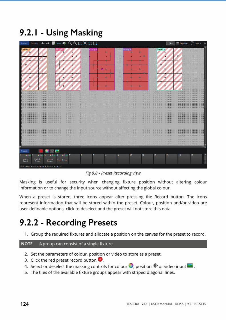
124 TESSERA - V3.1 | USER MANUAL - REV A | 9.2 - PRESETS
9.2.1 - Using Masking
Fig 9.8 - Preset Recording view
Masking is useful for security when changing fixture position without altering colour information or to change the input source without affecting the global colour.
When a preset is stored, three icons appear after pressing the Record button. The icons represent information that will be stored within the preset. Colour, position and/or video are user-definable options, click to deselect and the preset will not store this data.
9.2.2 - Recording Presets 1. Group the required fixtures and allocate a position on the canvas for the preset to record.
NOTE A group can consist of a single fixture.
2. Set the parameters of colour, position or video to store as a preset. 3. Click the red preset record button . 4. Select or deselect the masking controls for colour , position or video input . 5. The tiles of the available fixture groups appear with striped diagonal lines.

TESSERA - V3.1 | USER MANUAL - REV A | 9.2 - PRESETS 125
6. Only selected groups are stored into a Position preset. Once selected, the diagonal lines on the groups change to solid colour.If no group is selected, the following warning is shown.
7. Click an empty preset tile to store the new preset. 8. When double-clicking a preset, the preset recalls settings for associated groups.
9.2.3 - Editing PresetsTo change any parameters of a stored preset, the preset must be re-recorded. Double-click the stored preset tile, make changes and click the Preset Record button to save.
Right-click on a stored preset tile to rename or delete it.
Preset PropertiesClick once in a preset to open its property editor.

126 TESSERA - V3.1 | USER MANUAL - REV A | 9.2 - PRESETS
Name Option to rename the preset tile
Fade Time Select the cross-fade time
Fade Through Black Activate to go to black before crossfading to the new source input
Cross-fading This feature is only available on the Tessera M2 LED Processor
Switching inputs can be achieved by creating a Video preset for each input.
NOTE Other values like Colour and Position are not affected by the fade times and are committed as soon as the preset is activated. Crossfade only affects the source selection.
Crossfading between inputs can be achieved by storing the different inputs as presets with a fade time. To store presets to crossfade from one input to another follow these steps:
1. Select the first input for the preset (all tiles are changed to this input). 2. Click the Preset Record button . 3. Select a slot for the preset. 4. Activate a different input by double-clicking on a source pipeline tile (video thumbnail). 5. Repeat steps 2 and 3 to create a new preset for this input. 6. Click on each preset to view properties or set a fade time for the preset.
The presets are ready to crossfade between the inputs.
NOTE Note - Tessera M2 LED Processor has two input pipelines, each can process up to a 1920x1080 raster at 60Hz. When an input is selected, the input is mapped to the currently unused pipeline then fed into the mixer and scaler functions of the processor. Once any crossfading is complete, the other pipeline is then freed for the next selected input when selected.

TESSERA - V3.1 | USER MANUAL - REV A | 9.3 - LOG 127
9.3 - LogInformation about the processes and errors that occur within the processor can be viewed by clicking on Log.
This information can be stored in a USB drive or on the computer using the button Save the Log .

128 TESSERA - V3.1 | USER MANUAL - REV A | 9.4 - MOVING AROUND THE CANVAS
9.4 - Moving Around the CanvasMove Controls
Up, down, left and right
Vertical scrollbar
Arrow keys
Page up/down keys
Mouse wheel
Horizontal scrollbar
Arrow keys
Shift + mouse wheel
Zoom in and out
Use in the main toolbar
Ctrl + mouse wheel
Zoom to fit, Zoom 1:1 or Zoom to selection options
Drag the canvas Hold the space bar and left-click + drag with the mouse
Modify the active areaModify the scaler options
On the edges of the active area, click and drag as the cursor becomes a double-headed arrow
Move the active areaModify the scaler options
On the top-left of the active area, click and drag as the hand cursor appear
9.4.1 - NavigatorThe Navigator provides a simple way of moving around the canvas and adjusting zoom levels. A mini preview of the canvas is displayed, with a red box shows the current visible canvas area. Dragging the box moves the canvas view, and a slider is available for zooming in and out.
Open or close the Navigator window by:
l Clicking the button from the toolbar l Clicking the button intersecting the canvas Scrollbars. l Select Toggle Navigator from the canvas context menu. l Select Toggle Navigator from the View menu. l Press Ctrl+Shift+N (or ⌘+Shift+N on Mac)

TESSERA - V3.1 | USER MANUAL - REV A | 9.5 - PROJECT DATA EXPORT 129
9.5 - Project Data ExportTessera software has three types of files that can be exported: Canvas image, device layout and discovered devices.
9.5.1 - Export Canvas ImageTo export an image, navigate to Tools and select Export Canvas Image. Several options are displayed for the user to choose and control how exported images are rendered. After selecting export options, the user is prompted to select an export location, either on the local file system when using Tessera Remote or on a USB storage device attached to the processor when using the local user interface.
The exported image in PNG format is a pixel-accurate representation of the canvas and has the same dimensions as the canvas.
NOTE If using the exported image for content creation, we recommend using the image as a guide only. This avoids artefacts due to aliasing at the edges of small and rotated fixtures.
9.5.2 - Export Device LayoutTo export the device layout data as a CSV file, navigate to the Tools dropdown menu and select Export Device Layout. The CSV file contains a row for every fixture on the canvas. To choose the columns, select fields from the left list and press the right arrow to move them to the right list. To individually select multiple fields, Hold Ctrl(⌘ for Mac) and click each field.
After choosing export options, select a storage location, either on the local file system when using Tessera Remote or on a USB storage device attached to the processor when using the local user interface.
Data is exported in Comma- Separated Values (CSV) format, which can be opened with spreadsheet applications such as Microsoft Excel, or a simple text editor.
9.5.3 - Export Discovered DevicesExport discovered devices, exports information identical to the Online view therefore selected filter options, column hiding, and sorting also applies to the exported data. By default this includes:
l Port l Type l Serial Number l Firmware l Progress

130 TESSERA - V3.1 | USER MANUAL - REV A | 9.5 - PROJECT DATA EXPORT
l Port 1 Status l Port 2 Status l Temperature l Orientation l Status l Authentication
Navigate to the Tools dropdown menu and select Export Discovered Devices or from Online view and selecting Export Discovered Panels.
Data is exported in Comma-Separated Values (CSV) format.The exported data can be opened and manipulated in spreadsheet applications such as Microsoft Excel, or in simple text editors.
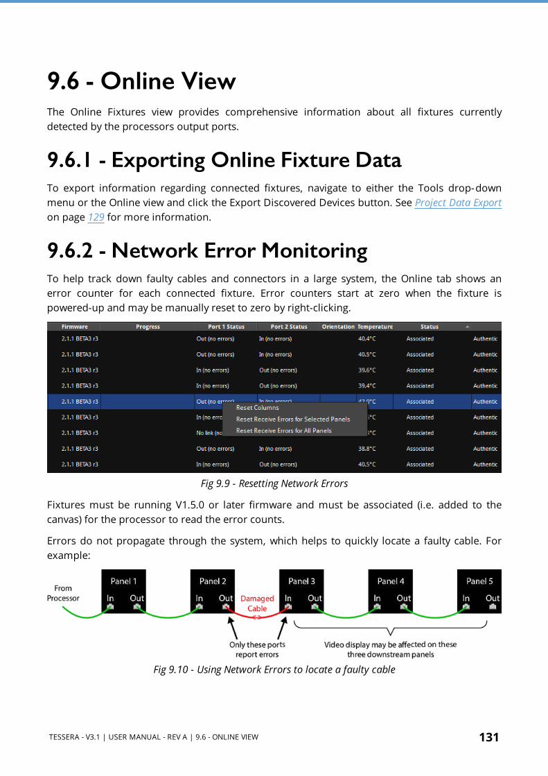
TESSERA - V3.1 | USER MANUAL - REV A | 9.6 - ONLINE VIEW 131
9.6 - Online ViewThe Online Fixtures view provides comprehensive information about all fixtures currently detected by the processors output ports.
9.6.1 - Exporting Online Fixture DataTo export information regarding connected fixtures, navigate to either the Tools drop-down menu or the Online view and click the Export Discovered Devices button. See Project Data Export on page 129 for more information.
9.6.2 - Network Error MonitoringTo help track down faulty cables and connectors in a large system, the Online tab shows an error counter for each connected fixture. Error counters start at zero when the fixture is powered-up and may be manually reset to zero by right-clicking.
Fig 9.9 - Resetting Network Errors
Fixtures must be running V1.5.0 or later firmware and must be associated (i.e. added to the canvas) for the processor to read the error counts.
Errors do not propagate through the system, which helps to quickly locate a faulty cable. For example:
Fig 9.10 - Using Network Errors to locate a faulty cable

132 TESSERA - V3.1 | USER MANUAL - REV A | 9.6 - ONLINE VIEW
The error counter values are not reset by events such as the link going up or down, or the fixture being disconnected and reconnected. This is useful for long-term tests as an unexpected disconnection does not increase the error count.
A small number of receive errors can be expected when hot-plugging data cables or power cycling fixtures or processor. This is normal behaviour and does not indicate a fault. At other times, any error count increase indicates a potential fault that should be investigated.
Error counters update every couple of seconds, which helps to correlate errors with intermittent external events that might cause data corruption (such as using radios or the switching of high-power loads nearby). In this case, either remove or relocate the source of the interference, or consider using shielded data cables.
NOTE Standard precautions must be taken if using shielded cables, as this can electrically connect the two device’s earthing. Ensure both devices are at the same earth potential (especially for the link between the processor and first fixture, as these are often connected to different power sources), otherwise the cable's screen can equalise this voltage, causing a current to flow down the screen, which itself risks corrupting data or damaging the cable or connected devices.

TESSERA - V3.1 | USER MANUAL - REV A | 9.7 - TOPOLOGY VIEW 133
9.7 - Topology ViewThe Topology View is exclusive to Tessera SX40 LED Processor s. Topology view shows the current network topology of the processor, connected Tessera XD Units and fixtures.
On the left, the letters A, B, C, & D represent the physical ports of the Tessera SX40. Green arrows represent a connection between the processor ports to any connected Tessera XD Distribution Units and their ports. The names of the Tessera XD Units are displayed for recognition.
If fixture chains are connected to any ports, the number of fixtures in the chain is displayed in the topology. Other topologies like daisy-chained Tessera XD Units and fixtures in closed-loop redundancy is also displayed in this view.
Fig 9.11 - Topology View with Fixtures connected to XD Units connected to SX40 ports A and B
When working with redundancy, cabling errors are displayed with red port numbers and shows the number of fixtures connected to each port.
NOTE Processor redundancy does not appear in the topology view and the offline processor does not show any connections until it is activated on the Failover pipeline tile. See Processor Redundancy on page 40 for more information.
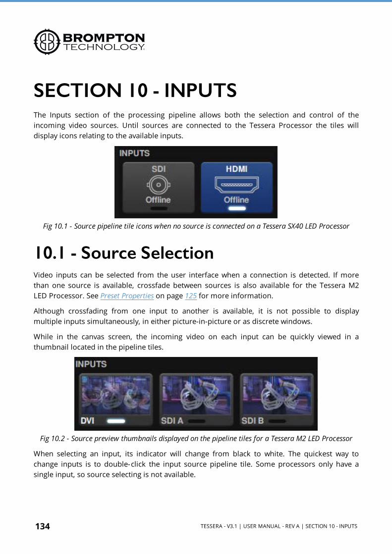
134 TESSERA - V3.1 | USER MANUAL - REV A | SECTION 10 - INPUTS
SECTION 10 - INPUTSThe Inputs section of the processing pipeline allows both the selection and control of the incoming video sources. Until sources are connected to the Tessera Processor the tiles will display icons relating to the available inputs.
Fig 10.1 - Source pipeline tile icons when no source is connected on a Tessera SX40 LED Processor
10.1 - Source SelectionVideo inputs can be selected from the user interface when a connection is detected. If more than one source is available, crossfade between sources is also available for the Tessera M2 LED Processor. See Preset Properties on page 125 for more information.
Although crossfading from one input to another is available, it is not possible to display multiple inputs simultaneously, in either picture-in-picture or as discrete windows.
While in the canvas screen, the incoming video on each input can be quickly viewed in a thumbnail located in the pipeline tiles.
Fig 10.2 - Source preview thumbnails displayed on the pipeline tiles for a Tessera M2 LED Processor
When selecting an input, its indicator will change from black to white. The quickest way to change inputs is to double-click the input source pipeline tile. Some processors only have a single input, so source selecting is not available.

TESSERA - V3.1 | USER MANUAL - REV A | 10.2 - HD SOURCES (FOR M2, T1, S4) 135
Any input can be used as a reference signal for Genlock. See Genlock Settings on page 214 for more information.
10.2 - HD Sources (for M2, T1, S4)
Fig 10.3 - Input Sources for Tessera SX40
10.2.1 - 3G SDI Input (M2 only)Each SDI input on the Tessera M2 LED Processor provides support for:
l 3G-SDI Level A l 3G-SDI Level B Dual-Link (Level B Dual-Stream is not supported) l HD-SDI l SD-SDI
Standard broadcast resolutions up to 1920x1080 are supported, with framerates between 23.98Hz to 60Hz and fractional frame rates such as 59.94Hz and 23.98Hz.
The supported video properties are:
l 10 bits per channel
l YCbCr 4:2:2
The physical connections to the SDI inputs are via standard BNC connectors. In addition to each input there is a thru re-clocked connector that allows for daisy-chaining a signal to a second processor or monitor.
10.2.2 - DVI Input (M2, T1, S4)The Tessera HD LED processors support digital (DVI-D) signals up to full HD 1080p resolution at frame rates from 24Hz to 60Hz to a maximum pixel clock of 148.5MHz. The M2 can receive analogue VGA/RGBHV inputs up to full HD (a suitable adaptor for the DVI- I input port is required).
136 TESSERA - V3.1 | USER MANUAL - REV A | 10.3 - 4K SOURCES (FOR SX40 AND S8)
The supported video properties are:
l 8 bits per channel
l RGB
l YCbCr 4:2:2
In addition to the DVI-I input there is also a thru re-clocked DVI-I output.
10.3 - 4K Sources (for SX40 and S8)
10.3.1 - 12G SDI InputBoth the Tessera SX40 and Tessera S8 LED Processorprovide support for:
l 12G-SDI 2S (SQ is not supported)
l 6G-SDI
l 3G-SDI Level A
l 3G-SDI Level B Dual-Link (Level B Dual-Stream is not supported
l HD-SDI
Standard broadcast resolutions up to 4096x2160 are supported, with framerates between 23.98Hz to 60Hz and fractional frame rates such as 59.94Hz and 23.98Hz.
The supported video properties are:
l 10 bits per channel
l YCbCr 4:2:2
The physical connections to the SDI inputs are via standard BNC connectors. In addition to each input there is a re-clocked thru connector that allows for daisy-chaining a signal to a second processor or monitor.
10.3.2 - HDMI 2.0 InputBoth the Tessera SX40 and Tessera S8 LED Processor supports HDMI 2.0 signals up to 4k DCI with customised resolutions at frame rates from 24Hz to 144Hz with 18Gbps bandwidth to a maximum pixel clock of 600MHz. The Tessera LED Processors do not support HDCP.
The Tessera SX40 and Tessera S8 can receive DVI-D and DisplayPort inputs (a suitable adaptor is required).
TESSERA - V3.1 | USER MANUAL - REV A | 10.3 - 4K SOURCES (FOR SX40 AND S8) 137
The supported video properties are:
l 8, 10 or 12 bits per channel
l RGB
l YCbCr 4:2:0
l YCbCr 4:2:2
l YCbCr 4:4:4
In addition to the HDMI 2.0 input there is also a re-clocked HDMI 2.0 output.

138 TESSERA - V3.1 | USER MANUAL - REV A | 10.4 - INPUT METADATA
10.4 - Input MetadataWhen an HDR source is connected to one of the Tessera LED Processor's inputs, its metadata can be viewed within the Source Control panel on the right-hand side of the interface. To open this panel, click the source of interest to bring up the Source Control panel on the right-hand side of the interface.
NOTE Correct metadata will be visible in the Source Control panel provided that:
1. The input source is able to send the metadata. 2. The source content has been authored with accurate metadata.
Different metadata will be available based on both the source input and content types.
10.4.1 - HDMI 2.0 (SX40 and S8)
Fig 10.4 - Incoming metadata from an HDR source through HDMI
Metadata is received from the source via InfoFrames over an HDMI 2.0 connection for the Tessera SX40 and Tessera S8 LED Processors. The metadata contains information about the content's format, brightness, and colour space allowing the Tessera SX40 and Tessera S8 LED Processors to automatically set these values for the received input. Should this incoming metadata be incorrect it can easily be corrected or changed using the Input Override. See Input Override on page 142 for more information

TESSERA - V3.1 | USER MANUAL - REV A | 10.4 - INPUT METADATA 139
Metadata Property Property Explanation
Status Status of the incoming source signal
Resolution Resolution of content being received from the source
Frame Rate Frame rate of the content being received from the source
Sampling Chroma subsampling compression of the incoming content
Bit Depth Bit depth of the incoming content. Can be 8, 10, or 12 bit
HDR StatusSummary of the incoming content's authored HDR colour and luminance settings. This always shows the HDR Format, Colour Space, and Max CLL
FormatThe HDR format used to author the incoming content. Can be PQ HDR10 or Hybrid Log Gamma (HLG)
Colour Space Colour space used for the incoming HDR content
Min and Max Display Mastering Luminance
The minimum and maximum display panel luminance for which the HDR content has been authored
Max Content Light Level (MaxCLL)
The maximum light level, in nits, any single pixel is expected to achieve for the incoming HDR content
Max Frame Average Light Level
The maximum average light level, in nits, for any single frame for the incoming HDR content
Red, Green, Blue, White Targets
The RGB and white point target coordinates to which the in coming HDR content has been authored

140 TESSERA - V3.1 | USER MANUAL - REV A | 10.4 - INPUT METADATA
10.4.2 - SDI (SX40, S8, M2)
Fig 10.5 - Incoming metadata from an HDR source through SDI
The SDI input does not send any metadata of the incoming content (beyond the resolution and frame rate) so information such as the colour space and HDR format (SX40 and S8 only) will have to be provided manually from the Input Override. See Input Override on page 142 for more information
Metadata Property Property Explanation
Status Status of the incoming source signal
Resolution Resolution of content being received from the source
Frame Rate Frame rate of the content being received from the source
Format The format of the SDI input (12G for SX40 and 3G for M2)

TESSERA - V3.1 | USER MANUAL - REV A | 10.4 - INPUT METADATA 141
10.4.3 - DVI (M2, S4, T1)
Fig 10.6 - Incoming metadata from an HDR source through SDI
Like SDI, DVI inputs do not send any metadata for the incoming content beyond the resolution and frame rate. Information about the colour format and colour space need to be set manually from the Input Override.See Input Override on page 142 for more information
Metadata Property Property Explanation
Status Status of the incoming source signal
Resolution Resolution of content being received from the source
Frame Rate Frame rate of the content being received from the source

142 TESSERA - V3.1 | USER MANUAL - REV A | 10.5 - INPUT OVERRIDE
10.5 - Input OverrideJust below the input metadata for a source (once its tile has been clicked) are the input override controls. These are used to set the properties of the incoming content such as colour format and colour space.
Fig 10.7 - Input override controls for the Tessera SX40 and S8
Because the Tessera SX40 and Tessera S8 LED Processors are capable of outputting HDR they have dedicated input override controls to set the required properties for incoming HDR content. See High Dynamic Range on page 57 for more information
When receiving content via HDMI 2.0 on either the Tessera SX40 or Tessera S8 LED Processors, the input properties will be automatically detected from the metadata sent via the InfoFrames. See Input Metadata on page 138 for more information
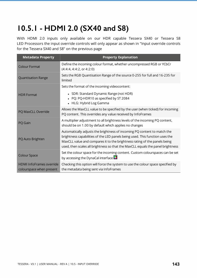
TESSERA - V3.1 | USER MANUAL - REV A | 10.5 - INPUT OVERRIDE 143
10.5.1 - HDMI 2.0 (SX40 and S8)With HDMI 2.0 inputs only available on our HDR capable Tessera SX40 or Tessera S8 LED Processors the input override controls will only appear as shown in "Input override controls for the Tessera SX40 and S8" on the previous page
Metadata Property Property Explanation
Colour FormatDefine the incoming colour format, whether uncompressed RGB or YCbCr (4:4:4, 4:4:2, or 4:2:0)
Quantisation RangeSets the RGB Quantisation Range of the source 0-255 for full and 16-235 for limited
HDR Format
Sets the format of the incoming videocontent:
l SDR: Standard Dynamic Range (not HDR) l PQ: PQ-HDR10 as specified by ST 2084 l HLG: Hybrid Log Gamma
PQ MaxCLL OverrideAllows the MaxCLL value to be specified by the user (when ticked) for incoming PQ content. This overrides any value received by InfoFrames
PQ GainA multiplier adjustment to all brightness levels of the incoming PQ content, should be on 1.00 by default which applies no changes
PQ Auto Brighten
Automatically adjusts the brightness of incoming PQ content to match the brightness capabilities of the LED panels being used. This function uses the MaxCLL value and compares it to the brightness rating of the panels being used, then scales all brightness so that the MaxCLL equals the panel brightness
Colour SpaceSet the colour space for the incoming content. Custom colourspaces can be set by accessing the DynaCal interface
HDMI InfoFrames override colourspace when present
Checking this option will force the system to use the colour space specified by the metadata being sent via InfoFrames

144 TESSERA - V3.1 | USER MANUAL - REV A | 10.5 - INPUT OVERRIDE
10.5.2 - SDI (SX40, S8, M2)
Fig 10.8 - Input override controls for SDI inputs on the Tessera SX40 (left) and M2 (right)
Both the Tessera SX40 and Tessera M2 LED Processors can receive SDI inputs. Only the Tessera SX40 and S8 are HDR capable meaning their input override controls are more extensive than for the Tessera M2 which allows only for the colour space to be set.
NOTE SDI connections do not provide any metadata for setting the input format properties. This means the values will need to be set manually.
For the Tessera SX40 and Tessera M2 they are set to the values shown above.
Metadata Property Property Explanation
HDR Format
Sets the format of the incoming video content:
l SDR: Standard Dynamic Range (not HDR) default l PQ: PQ-HDR10 as specified by ST 2084 l HLG: Hybrid Log Gamma
PQ MaxCLL OverrideAllows the MaxCLL value to be specified by the user (when ticked) for incoming PQ content. This overrides any value received by InfoFrames
PQ GainA multiplier adjustment to all brightness levels of the incoming PQ content, should be on 1.00 by default which applies no changes
PQ Auto Brighten
Automatically adjusts the brightness of incoming PQ content to match the brightness capabilities of the LED panels being used. This function uses the MaxCLL value and compares it to the brightness rating of the panels being used, then scales all brightness so that the MaxCLL equals the panel brightness
Colour SpaceSet the colour space for the incoming content. Custom colourspaces can be set by accessing the DynaCal interface

TESSERA - V3.1 | USER MANUAL - REV A | 10.5 - INPUT OVERRIDE 145
10.5.3 - DVI (M2, S4, T1)
Fig 10.9 - Input override controls for DVI inputs
NOTE DVI connections do not provide any metadata for setting the input format properties. This means the values will need to be set manually.
For the Tessera M2, S4, and T1 they are set to the values shown above.
Metadata Property Property Explanation
Colour FormatDefine the incoming colour format, whether uncompressed RGB or YPbPr of the Rec.601 or Rec.709 colour spaces
Colour SpaceSet the colour space for the incoming content. Custom colourspaces can be set by accessing the DynaCal interface
146 TESSERA - V3.1 | USER MANUAL - REV A | 10.6 - INPUT COLOUR CONTROL
10.6 - Input Colour Control
10.6.1 - Black LevelThe black level control affects the base level brightness of the darkest content for the incoming feed. Modifying this value will affect the signal gradually but will be most pronounced at the lower end of the video signal nearest black. For optimum adjustment of the black level, a PLUGE or greyscale line-up pattern can be useful.
NOTE What is PLUGE? Picture line-up generation equipment (PLUGE or pluge) is equipment used to generate greyscale test patterns to adjust the black level and contrast of a picture monitor. Images generated from these tools can be saved as bitmaps and these images are sometimes referred to as PLUGE themselves.
10.6.2 - ContrastJust as the black level control sets the threshold of the base level of dark content, the contrast slider sets the threshold level of bright content. Boosting this level will increase the differential in luminance between the darkest content and the brightest content.
10.6.3 - HueThe hue parameter adjusts the spectrum of the incoming video feed. At the extreme this will reverse the colours assigned to each area of a given hue.
10.6.4 - SaturationThe saturation parameter adjusts the depth of colour. When reduced the image changes to monochrome with only brightness information intact. Increasing saturation will enhance colour to give a more vibrant image.
10.6.5 - RGB ShadowThis option is for setting the black level specifically for each primary colour for the selected input. These sliders equate to a setting for the black level of each specific colour.
10.6.6 - RGB HighlightRGB Highlight is for adjusting the contrast (white level) for each of the primary colours.

TESSERA - V3.1 | USER MANUAL - REV A | 10.7 - HISTOGRAMS 147
10.7 - HistogramsTessera LED Processors offer a selection of histograms to depict distribution of pixels across the possible range of a colour or colours of the incoming video feed in real time after they have been modified by the input colour controls. There are six different histograms available, and all histograms can be displayed linearly or logarithmically:
l Luminance l Red l Green l Blue l Red, green and blue with separate histograms l Red, green, blue and luminance with overlaid histograms
The main use of histograms is to identify and compensate for perceived deficiencies in the incoming video feed. The user can monitor how changes to the input colour controls can affect the colour content of that feed. Adjusting the controls can boost the colour depth of the displayed signal, resulting in a better distribution of peaks in the histogram.
The X-Axis of each histogram is graded from 0% to 100%, a column is used to indicate how much content there is at that percentage of the given colour. The Y-Axis shows the amount of content as a percentage, it automatically scales to fill the axis.
The logarithmic scale will accentuate small columns so tiny areas of a colour can be visualized in instances where one percentage dwarfs all others.
Fig 10.10 - Test pattern showing colour bars at 75% and the corresponding Linear RGB histogram
The above picture shows a test pattern and its corresponding Linear RGB histogram. Note that there are clear columns at 75% for each of the three primaries. This is because all colours are either primary colours at 75% (red, green and blue sections) or secondary colours made from combinations of the primaries at 75% (cyan, yellow, magenta and white sections).
There is also a large peak at 0% on the left which shows the amount of black in the image. There is a clear peak on the right which shows an area of 100% RGB and is caused by the single block of 100% white towards the bottom left of the image (white is noticeably brighter than the grey-looking vertical section white which is made by mixing 75% red, green and blue).
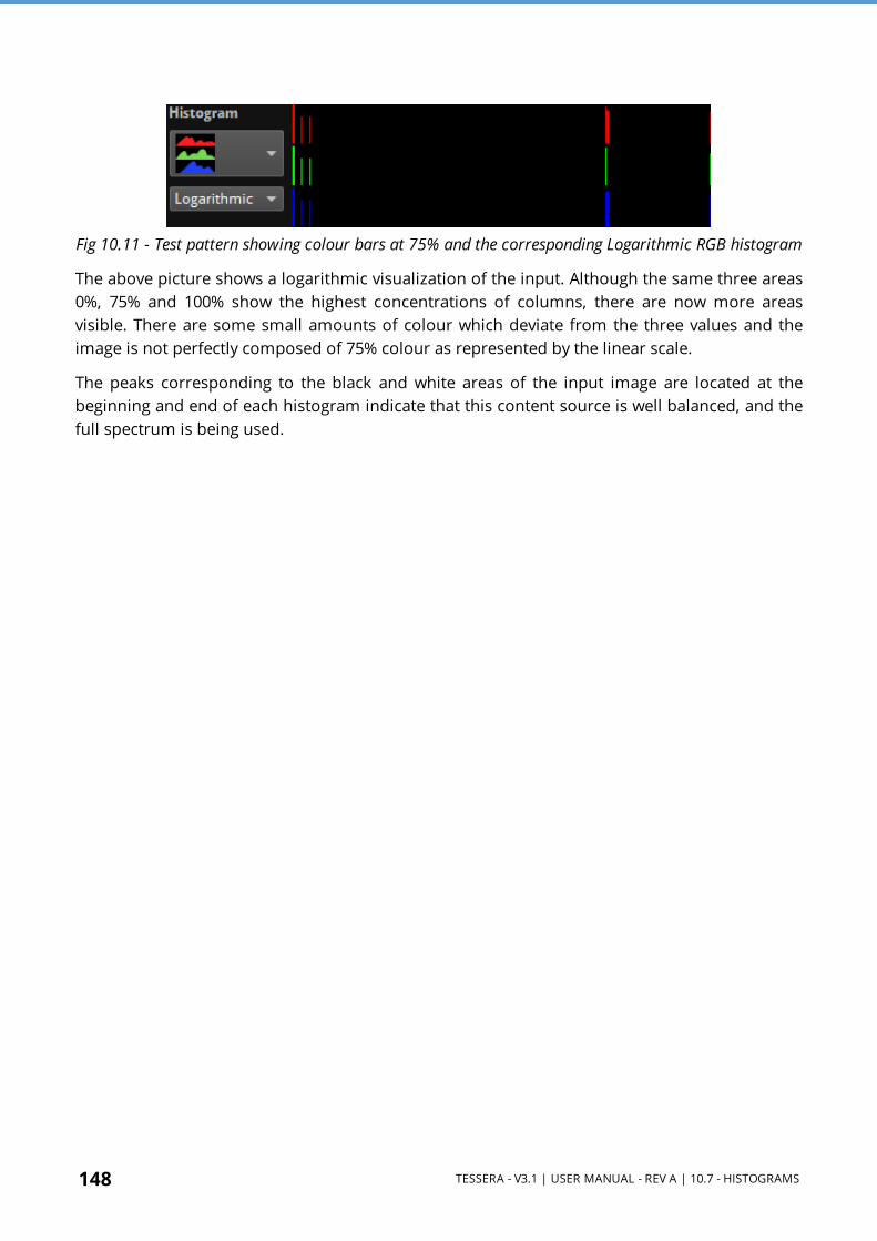
148 TESSERA - V3.1 | USER MANUAL - REV A | 10.7 - HISTOGRAMS
Fig 10.11 - Test pattern showing colour bars at 75% and the corresponding Logarithmic RGB histogram
The above picture shows a logarithmic visualization of the input. Although the same three areas 0%, 75% and 100% show the highest concentrations of columns, there are now more areas visible. There are some small amounts of colour which deviate from the three values and the image is not perfectly composed of 75% colour as represented by the linear scale.
The peaks corresponding to the black and white areas of the input image are located at the beginning and end of each histogram indicate that this content source is well balanced, and the full spectrum is being used.

TESSERA - V3.1 | USER MANUAL - REV A | 10.7 - HISTOGRAMS 149
10.7.1 - Setting Colour Controls with the Aid of HistogramsHistograms are useful for determining if an incoming signal is filling the entire spectrum of colour and brightness.
NOTE When choosing an image to balance, use an image from live event content throughout the project, an image with a wide variety of colours and hues, or a suitable test pattern.
Fig 10.12 - A fairly washed out incoming signal on DVI (see thumbnail top left) with the corresponding histogram for red, green and blue when the Input

150 TESSERA - V3.1 | USER MANUAL - REV A | 10.7 - HISTOGRAMS
Fig 10.13 - Adjusting the black level control will make the blacks look darker and the concentrations of colour now reach down to 0% on the scale
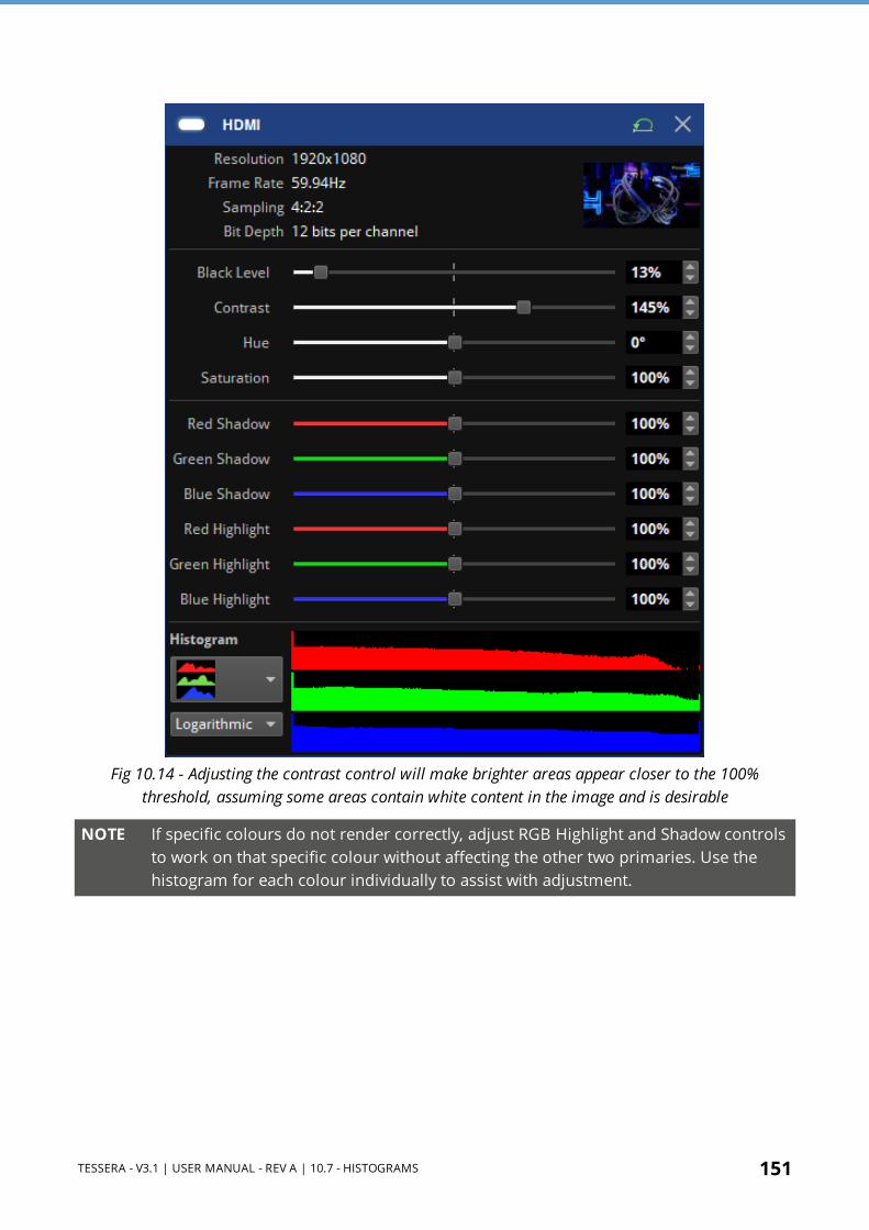
TESSERA - V3.1 | USER MANUAL - REV A | 10.7 - HISTOGRAMS 151
Fig 10.14 - Adjusting the contrast control will make brighter areas appear closer to the 100% threshold, assuming some areas contain white content in the image and is desirable
NOTE If specific colours do not render correctly, adjust RGB Highlight and Shadow controls to work on that specific colour without affecting the other two primaries. Use the histogram for each colour individually to assist with adjustment.

152 TESSERA - V3.1 | USER MANUAL - REV A | SECTION 11 - PROCESSING
SECTION 11 - PROCESSING
Fig 11.1 - Processing pipeline tiles, featuring Scaling and Chromatune's Colour Replace, 14-Way Colour Correction, and Curves
11.1 - Scaling and CroppingThe Tessera M2 and T1 LED processors support scaling and cropping of the incoming feed. The Tessera SX40 and S8 LED processors support scaling. These functions are achieved using two settings: Viewport and Active Area.
Fig 11.2 - Scaler property editor

TESSERA - V3.1 | USER MANUAL - REV A | 11.1 - SCALING AND CROPPING 153
11.1.1 - ViewportThe Viewport settings define the region of interest from the incoming feed which is captured to the canvas. By default, when activating the Scaler pipeline tile, the settings will be set to fit the canvas, with full size viewport and full size Active Area with stretch Zoom mode. The Viewport is scaled and mapped onto the Active Area according to the Zoom mode.
Fig 11.3 - Scaler zoom mode options

154 TESSERA - V3.1 | USER MANUAL - REV A | 11.1 - SCALING AND CROPPING
1:1 ModeThe 1:1 mode selects and crops an area of the input maintaining the original Viewport image size.
Dimensions l Left: Determine the column of pixels that will appear on the left of the canvas l Top: Determine the row of pixels that will appear on the top of the canvas l Width: Determine the total width of the source (Maximum width will be the canvas width
minus the Left value) l Height: Determine the total height of the source (Maximum height will be the canvas
height minus the Top value)
Fig 11.4 - Canvas is scaled to 1:1

TESSERA - V3.1 | USER MANUAL - REV A | 11.1 - SCALING AND CROPPING 155
Fit ModeThe Fit mode selects a section of the input and scales it to fit within the active area while maintaining the aspect ratio.
Dimensions l Left: Determine the column of pixels that will appear on the left of the canvas l Top: Determine the row of pixels that will appear on the top of the canvas l Width: Determine the total width of the source before being stretched (maximum width
will be the canvas width minus the Left value) l Height: Determine the total height of the source before being stretched (maximum height
will the canvas height minus the Top value)
Fig 11.5 - Scaled to fit within the active area

156 TESSERA - V3.1 | USER MANUAL - REV A | 11.1 - SCALING AND CROPPING
Fill ModeThe Fill mode selects a section of the input and scales it to fill the active area while maintaining the aspect ratio.
Dimensions l Left: Determine the column of pixels that will appear on the left of the canvas l Top: Determine the row of pixels that will appear on the top of the canvas l Width: Determine the total width of the source before being stretched (maximum width
will be the canvas width minus the Left value) l Height: Determine the total height of the source before being stretched (maximum height
will be the canvas height minus the Top value)
Fig 11.6 - Scaled to fill source to active area
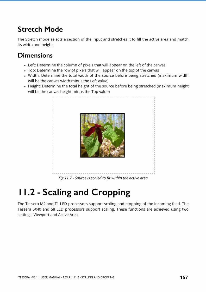
TESSERA - V3.1 | USER MANUAL - REV A | 11.2 - SCALING AND CROPPING 157
Stretch ModeThe Stretch mode selects a section of the input and stretches it to fill the active area and match its width and height.
Dimensions l Left: Determine the column of pixels that will appear on the left of the canvas l Top: Determine the row of pixels that will appear on the top of the canvas l Width: Determine the total width of the source before being stretched (maximum width
will be the canvas width minus the Left value) l Height: Determine the total height of the source before being stretched (maximum height
will be the canvas height minus the Top value)
Fig 11.7 - Source is scaled to fit within the active area
11.2 - Scaling and CroppingThe Tessera M2 and T1 LED processors support scaling and cropping of the incoming feed. The Tessera SX40 and S8 LED processors support scaling. These functions are achieved using two settings: Viewport and Active Area.
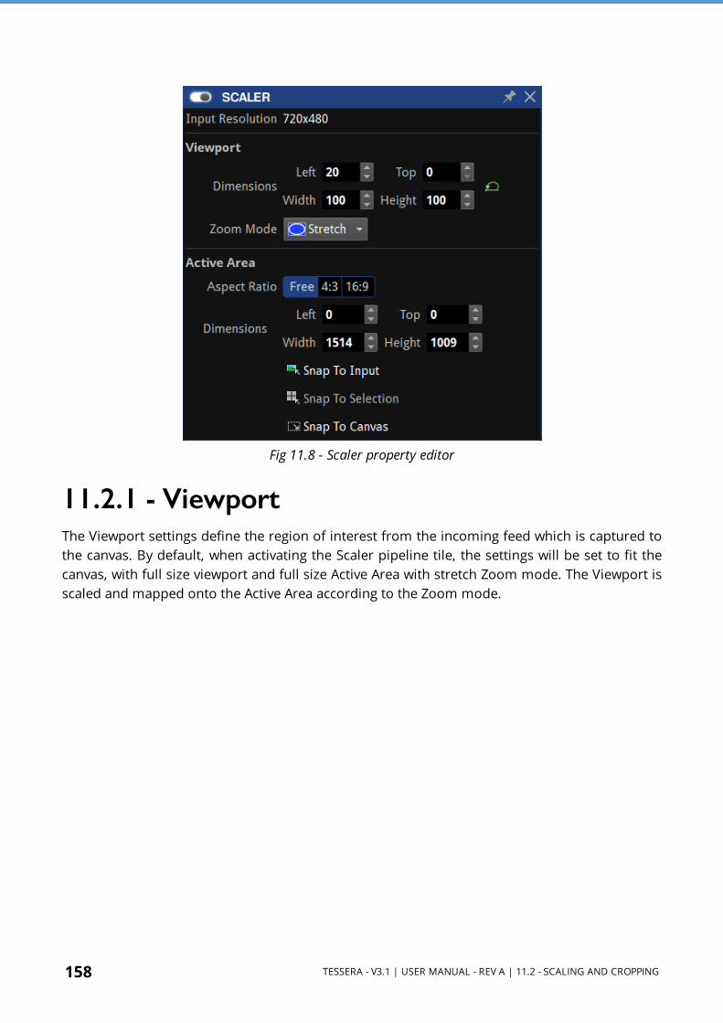
158 TESSERA - V3.1 | USER MANUAL - REV A | 11.2 - SCALING AND CROPPING
Fig 11.8 - Scaler property editor
11.2.1 - ViewportThe Viewport settings define the region of interest from the incoming feed which is captured to the canvas. By default, when activating the Scaler pipeline tile, the settings will be set to fit the canvas, with full size viewport and full size Active Area with stretch Zoom mode. The Viewport is scaled and mapped onto the Active Area according to the Zoom mode.

TESSERA - V3.1 | USER MANUAL - REV A | 11.2 - SCALING AND CROPPING 159
Fig 11.9 - Scaler zoom mode options
1:1 ModeThe 1:1 mode selects and crops an area of the input maintaining the original Viewport image size.
Dimensions l Left: Determine the column of pixels that will appear on the left of the canvas l Top: Determine the row of pixels that will appear on the top of the canvas l Width: Determine the total width of the source (Maximum width will be the canvas width
minus the Left value) l Height: Determine the total height of the source (Maximum height will be the canvas
height minus the Top value)

160 TESSERA - V3.1 | USER MANUAL - REV A | 11.2 - SCALING AND CROPPING
Fig 11.10 - Canvas is scaled to 1:1

TESSERA - V3.1 | USER MANUAL - REV A | 11.2 - SCALING AND CROPPING 161
Fit ModeThe Fit mode selects a section of the input and scales it to fit within the active area while maintaining the aspect ratio.
Dimensions l Left: Determine the column of pixels that will appear on the left of the canvas l Top: Determine the row of pixels that will appear on the top of the canvas l Width: Determine the total width of the source before being stretched (maximum width
will be the canvas width minus the Left value) l Height: Determine the total height of the source before being stretched (maximum height
will the canvas height minus the Top value)
Fig 11.11 - Scaled to fit within the active area

162 TESSERA - V3.1 | USER MANUAL - REV A | 11.2 - SCALING AND CROPPING
Fill ModeThe Fill mode selects a section of the input and scales it to fill the active area while maintaining the aspect ratio.
Dimensions l Left: Determine the column of pixels that will appear on the left of the canvas l Top: Determine the row of pixels that will appear on the top of the canvas l Width: Determine the total width of the source before being stretched (maximum width
will be the canvas width minus the Left value) l Height: Determine the total height of the source before being stretched (maximum height
will be the canvas height minus the Top value)
Fig 11.12 - Scaled to fill source to active area
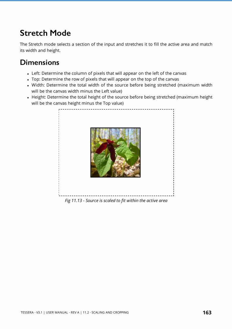
TESSERA - V3.1 | USER MANUAL - REV A | 11.2 - SCALING AND CROPPING 163
Stretch ModeThe Stretch mode selects a section of the input and stretches it to fill the active area and match its width and height.
Dimensions l Left: Determine the column of pixels that will appear on the left of the canvas l Top: Determine the row of pixels that will appear on the top of the canvas l Width: Determine the total width of the source before being stretched (maximum width
will be the canvas width minus the Left value) l Height: Determine the total height of the source before being stretched (maximum height
will be the canvas height minus the Top value)
Fig 11.13 - Source is scaled to fit within the active area

164 TESSERA - V3.1 | USER MANUAL - REV A | 11.3 - ACTIVE AREA
11.3 - Active AreaOn the canvas, the Active Area is indicated by the grey mask with a dashed border.
Fig 11.14 - The canvas with the Active Area shown by a dashed border
Having determined the region of interest to be captured from the incoming feed using the Viewport, that region can then be sized or moved as desired. Modifying the active area values, will move or scale the area cropped in the viewport.
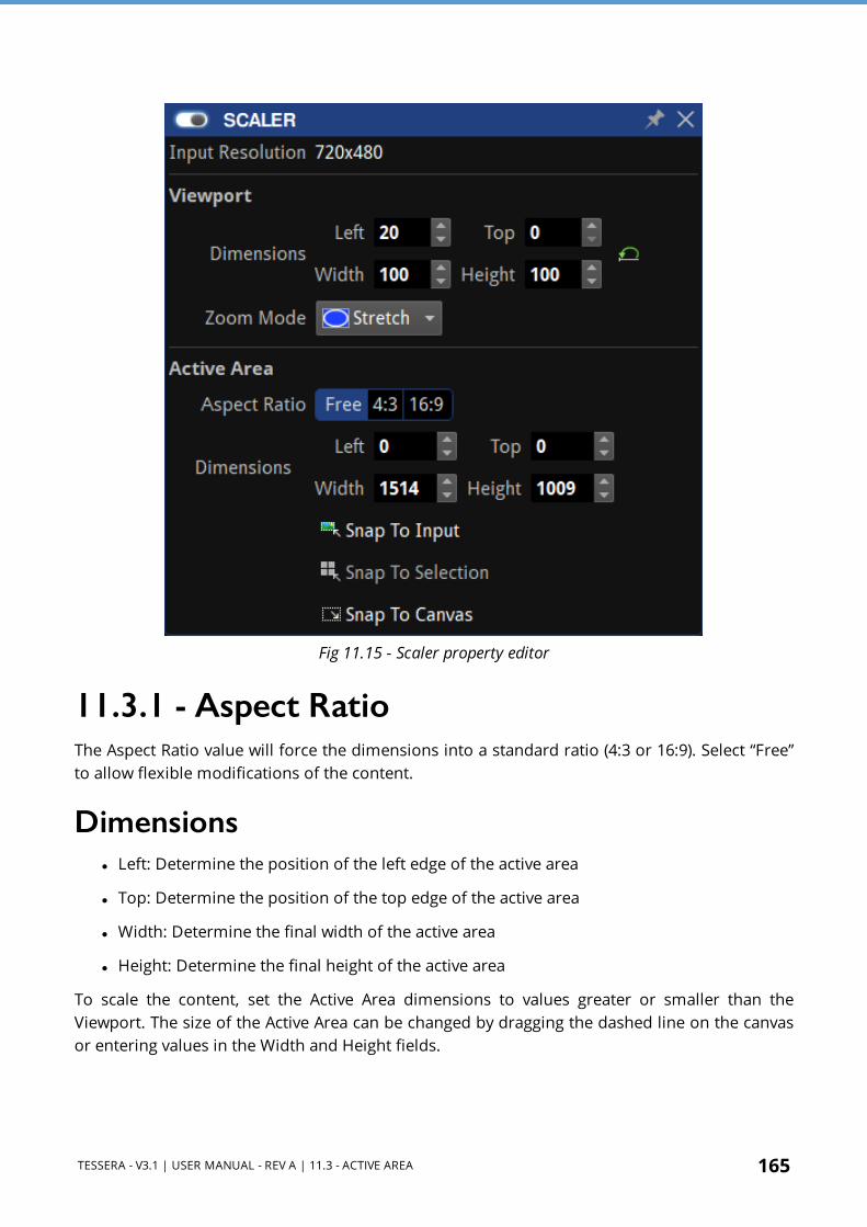
TESSERA - V3.1 | USER MANUAL - REV A | 11.3 - ACTIVE AREA 165
Fig 11.15 - Scaler property editor
11.3.1 - Aspect RatioThe Aspect Ratio value will force the dimensions into a standard ratio (4:3 or 16:9). Select “Free” to allow flexible modifications of the content.
Dimensions l Left: Determine the position of the left edge of the active area
l Top: Determine the position of the top edge of the active area
l Width: Determine the final width of the active area
l Height: Determine the final height of the active area
To scale the content, set the Active Area dimensions to values greater or smaller than the Viewport. The size of the Active Area can be changed by dragging the dashed line on the canvas or entering values in the Width and Height fields.

166 TESSERA - V3.1 | USER MANUAL - REV A | 11.3 - ACTIVE AREA
NOTE The active area cannot be greater than the maximum canvas size.
To modify the active area, move the mouse cursor to the top-left corner of the active area until it becomes a hand , then click and drag the area. Positions can also be determined by adjusting the top and left coordinates manually.
Snap to InputAdjust the active area size to match the input source size.
Fig 11.16 - Snap to Input
Snap to SelectionAdjust the active area size to match the size of the selection of fixtures. To resize the input source to fit all visible fixtures, select the chosen fixtures and click the Snap to Selection button.
Fig 11.17 - Active area scaled to snap to fixture selection

TESSERA - V3.1 | USER MANUAL - REV A | 11.3 - ACTIVE AREA 167
Snap to CanvasAdjust the active area size to match the canvas size.
Fig 11.18 - The active are is set to the canvas dimensions

168 TESSERA - V3.1 | USER MANUAL - REV A | 11.4 - CHROMATUNE
11.4 - ChromaTune
Fig 11.19 - ChromaTune pipeline tiles: Colour Replace, 14-Way Colour Correction, and Curves
ChromaTune consists of two advanced colour correction features. One is Colour Replace, which gives the user advanced control to manipulate one specific colour with flexibility. The other is 14-way Colour Correction which enables adjusting one or a number of pre-defined colours by modifying their Hue, Saturation or Brightness.
11.4.1 - Colour ReplaceColour Replace allows one colour of an incoming source to be replaced by another. The Enable toggle button shown in the top-left activates the effect.
Fig 11.20 - Colour Replace property editor
l From: Select the original colour to be modified. Select a colour by clicking on the colour chip, or by clicking the eyedropper to select a colour from the incoming source on the canvas. The arrows next to the eyedropper transfer the colour from the respective colour chip to the other colour chip.
l To: Select a colour target to replace the From colour with. The colour can be chosen in the same way as From, by clicking on the colour chip and selecting from the colour picker, or by using the eyedropper tool. The arrows next to the eyedropper transfer the colour from the respective colour chip to the other colour chip.

TESSERA - V3.1 | USER MANUAL - REV A | 11.4 - CHROMATUNE 169
Fig 11.21 - Selecting a colour from the colour picker.
l Colour Tolerance: Determines the Hue range that is affected by the modifications. l Brightness Tolerance: Determines the Brightness range that is affected by the
modifications. l Apply to Hue, Apply to Saturation, Apply to Brightness These checkboxes apply the
tolerance settings to their respective parameters. l Softness: Determines the amount of softness applied to the edges of the correction matte.
The higher the value the smoother the transition between the area affected by the colour change and those areas not affected.
l Strength: Determines how much the modifications affect the original image. l View Matte: This shows the grayscale correction matte used to show the level of change
that occurs for each pixel. White areas show areas affected whilst black areas show areas that remain unchanged.
l Method: o Set To Colour directly changes the affected pixels of the To colour o Transform To Colour changes affected pixels toward the To colour using HSL
interpolation. The amount of change for affected pixels is dependent on how close the pixels are to the From colour.
Fig 11.22 - The colour replace pipeline tile indicates which colours have been altered

170 TESSERA - V3.1 | USER MANUAL - REV A | 11.4 - CHROMATUNE
Colour Replace ExamplesA red pepper can be changed into green pepper easily. Here is the original red pepper image:
Fig 11.23 - Original red pepper
Select a red colour from the from the canvas using the eyedropper tool, and a suitable green from the colour picker:
Fig 11.24 - From and To colour chips with red changed to green.
This results in the following:
Fig 11.25 - The resulting image after the From To operation
To turn the pepper completely green requires some adjustment, in this case increasing the Hue Tolerance parameter to 25%, as seen in the image below:
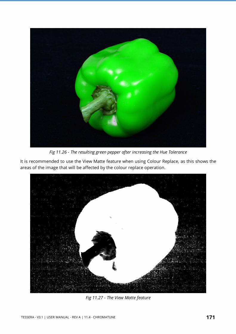
TESSERA - V3.1 | USER MANUAL - REV A | 11.4 - CHROMATUNE 171
Fig 11.26 - The resulting green pepper after increasing the Hue Tolerance
It is recommended to use the View Matte feature when using Colour Replace, as this shows the areas of the image that will be affected by the colour replace operation.
Fig 11.27 - The View Matte feature

172 TESSERA - V3.1 | USER MANUAL - REV A | 11.4 - CHROMATUNE
11.4.2 - 14-way Colour Correct
Fig 11.28 - 14 way colour correct pipeline tile with all colours adjusted
The 14- way Colour Correct feature allows singular or multiple pre- defined colours to be adjusted without affecting other colours. Hue, saturation and brightness controls are provided for each of the primary, secondary and tertiary colours. Black and white can be adjusted using RGB gains.
Fig 11.29 - 14-way colour correct property editor
Adjustments are made by entering a numerical value, or by clicking and dragging left/right to decrease/increase the value. The values of a colour can be reset to defaults by clicking in the reset button , located on the right of each row. The reset icon in the menu title bar will reset all values.
While in the Canvas View, the toolbar icon for 14-way Colour Correct indicates colours that are actively corrected.

TESSERA - V3.1 | USER MANUAL - REV A | 11.4 - CHROMATUNE 173
11.4.3 - Curves
Fig 11.30 - Colour Curves pipeline tile with real-time preview of colour channel curve settings
In addition to the Colour Replace and 14-Way Colour Corrector features, from Tessera v2.3 onwards on the Tessera SX40 and S8 LED Processors, ChromaTune now offers curves covering red, green, blue and white channels. This enables the video levels for each colour channel to be manipulated by creating custom transfer curves. To adjust the colour, first select the desired curve from the drop-down menu then use the mouse to select a point on the curve and drag to desired position. For each change made, a dot will appear on the curve to indicate position. Colour changes are made in real-time.
There is also a reset button for resetting curve changes.
This may be used creatively to adjust the ‘look’ of the video (e.g. adding an ‘S’ curve to add m re contrast), or as a tool to fine tune the appearance of the screen for ambient viewing conditions and/or on-camera performance.
Fig 11.31 - Curves property editor, showing a colour selection drop-down menu, adjust the curves by dragging the colour curve

174 TESSERA - V3.1 | USER MANUAL - REV A | SECTION 12 - TEST PATTERNS
SECTION 12 - TEST PATTERNS
Fig 12.1 - Test Pattern Pipeline tile in deactivated state
12.1 - Processor Test PatternsAll Tessera LED Processors have a selection of test patterns that can be used to check the performance of fixtures and verify that a fixture layout is correct.
Scrolling test patterns will always move exactly one pixel horizontally and/or vertically, therefore motion should be perfectly smooth. Any juddering, double/dropped frames or tearing between fixtures would indicate issues on the network, issues with the fixtures themselves or their positioning on the canvas.
To activate test patterns:
l Double-click on the Pattern pipeline tile. l Click once in the enable button on the property editor title bar l Click once in the desired test pattern to activate it.
Fig 12.2 - Tessera LED Processor test patterns property editor
Fig 12.3 - Test Pattern pipeline tile, indicates the current active test pattern
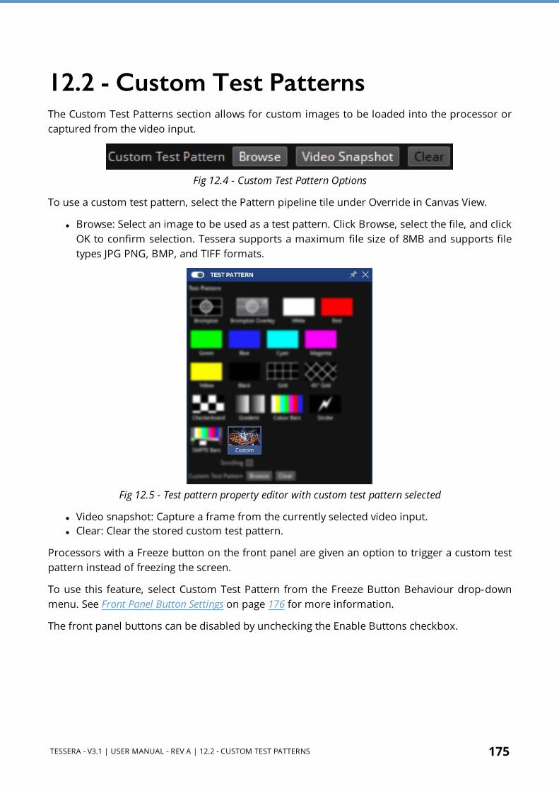
TESSERA - V3.1 | USER MANUAL - REV A | 12.2 - CUSTOM TEST PATTERNS 175
12.2 - Custom Test PatternsThe Custom Test Patterns section allows for custom images to be loaded into the processor or captured from the video input.
Fig 12.4 - Custom Test Pattern Options
To use a custom test pattern, select the Pattern pipeline tile under Override in Canvas View.
l Browse: Select an image to be used as a test pattern. Click Browse, select the file, and click OK to confirm selection. Tessera supports a maximum file size of 8MB and supports file types JPG PNG, BMP, and TIFF formats.
Fig 12.5 - Test pattern property editor with custom test pattern selected
l Video snapshot: Capture a frame from the currently selected video input. l Clear: Clear the stored custom test pattern.
Processors with a Freeze button on the front panel are given an option to trigger a custom test pattern instead of freezing the screen.
To use this feature, select Custom Test Pattern from the Freeze Button Behaviour drop-down menu. See Front Panel Button Settings on page 176 for more information.
The front panel buttons can be disabled by unchecking the Enable Buttons checkbox.

176 TESSERA - V3.1 | USER MANUAL - REV A | 12.3 - FIXTURE TEST PATTERNS
12.3 - Fixture Test PatternsIn addition to processor test patterns, individual fixtures also contain a set of pre-programmed test patterns. Individual or groups of fixtures can display patterns by selecting them in Canvas View. See Device Properties on page 74 for more information.
12.4 - Freeze/BlackoutDouble-clicking the Freeze pipeline tile or pressing the physical Freeze button on the processor will pause the incoming video signal and hold the final frame indefinitely. Pressing the freeze button again will resume live video. Freeze can also be triggered by clicking the enable button
in the Freeze property editor.
Double-clicking the Blackout pipeline tile or pressing the physical Blackout button will cause all panels to display black. Pressing the button again will resume live video. Blackout can also be triggered by clicking the enable button in the Blackout property editor.
12.5 - Front Panel Button SettingsTessera SX40 S8 and S4 LED Processors feature 2 buttons on the front panel to freeze or blackout the output on fixtures. By default, these perform the same functions as the buttons in the GUI. The buttons illuminate red while activated.
Fig 12.6 - SX40 front panel buttons
The front panel buttons can be disabled from the test patterns property editor on a per-project basis. The Freeze button can also be customised to show a custom test pattern/ bitmap instead of freezing.

TESSERA - V3.1 | USER MANUAL - REV A | 12.5 - FRONT PANEL BUTTON SETTINGS 177
Fig 12.7 - Tessera Test pattern property editor, with Freeze button behaviour drop-down menu options
If needed, failover can also be triggered by pressing both buttons at the same time when Tessera SX40 is cabled for Processor redundancy. This can be enabled or disabled in the Failover property editor.
Fig 12.8 - 7 Check box to enable failover when both physical buttons on processor are pressed
The front panel buttons can be disabled by unchecking the Enable Buttons checkbox.

178 TESSERA - V3.1 | USER MANUAL - REV A | SECTION 13 - GLOBAL COLOUR
SECTION 13 - GLOBAL COLOURThe following controls are available in the Global Colour pipeline tile and apply to all fixtures in a project unless those fixtures (or groups) have been overridden. See Per-Fixture and Per-Group Colour Override on page 72 for more information.
Fig 13.1 - Colour pipeline tile, as shown in the Tessera user interface
Fig 13.2 - Global Colour property editor

TESSERA - V3.1 | USER MANUAL - REV A | 13.1 - BRIGHTNESS 179
13.1 - BrightnessThe brightness slider allows adjustments for light output on fixtures. As all fixture types are calibrated when the profile is written, the brightness slider is expressed in Nits (candela/m2). This means arrays with different fixtures can quickly be set to the same output level.
Where more than one type of fixture with different maximum brightness values is used, the slider has no effect on a fixture's brightness once its maximum value is exceeded. The brightness slider will default using the brightest value that all the fixtures in a project can reach.
Example: If a project consists of two different types of fixtures, one of which has a maximum output of 5000 Nits and another has a maximum brightness of 2000 Nits, the default value of the brightness slider will be 2000 Nits. However, the maximum value of the slider will be the value of the brightest fixture in the project, so in this example it would be 5000 Nits.
NOTE To control the brightness of an array including different types of fixtures whilst maintaining relative brightness, leave brightness values at default and modify the intensity slider.
13.2 - Colour TemperatureThe Temperature slider allows the user to adjust the white balance of attached fixtures in a range from 2,000-11,000 Kelvin. By default, this value is set to 6,504K. Since Tessera V3.0 the Colour Temperature updates in real time on the LED panels while the slider is being moved.
13.3 - GammaGamma can be modified in a range from 0.2 up to 4.0 (default 2.35). Gamma correction is a way to adjust the brightness of mid-tones in the image without affecting the very dark or very bright areas of the image. A higher value results in lower brightness overall.
If images are not gamma encoded, they allocate too many bits or bandwidth to highlights that humans cannot differentiate, too few bits/bandwidth to shadow values that humans are sensitive to, and would require more bits/bandwidth to maintain the same visual quality.
By increasing the differential between areas of shadow and light in parts of the luminance curve of an image or video, it is possible to increase details that can be perceived by the human eye. Gamma correction is done by a simple function, images are encoded with a gamma constant equivalent to about 0.45 and so are decoded with a gamma of approximately 2.2. The gamma value in the processor is set by default to 2.35.
180 TESSERA - V3.1 | USER MANUAL - REV A | 13.3 - GAMMA
NOTE Prior Mac OSX versions to Snow Leopard encoded at 0.55 and hence decoded at 1.8. In order to obtain best results, a lower gamma value on the display output was set. Since Mac OSX Snow Leopard release, Apple has changed their default gamma values to a value more in line with the 0.45/2.2 ratio used by other manufacturers.
Though HDR video does not use a gamma curve, the Gamma value will affect "High Dynamic Range" on page 57 footage in the same way it would SDR footage.
Since Tessera V3.0 the Gamma updates in real time on the LED panels while the slider is being moved.

TESSERA - V3.1 | USER MANUAL - REV A | 13.4 - DARK MAGIC 181
13.4 - Dark MagicLED panels are often run at a lower brightness than their maximum capability, e.g. for indoor and 'on-camera' applications. This results in an unavoidable reduction in effective bit depth, which can lead to visible artefacts such as banding and loss of detail, especially in dark areas of the image.
Enabling Dark Magic will increase the visual quality of the output when operating at low brightness. A small amount of noise may become visible at short viewing distances, therefore in some circumstances when the fixtures are close the viewer, it may be preferable to uncheck the Dark Magic checkbox.
Fig 13.3 - Dark Magic Tick box in Global Colour property editor
The greatest improvements can be seen when running very high brightness panels at a much lower brightness, adjusted via the Brightness control.
Dark Magic is available for all Tessera fixtures that use the R2 receiver card.

182 TESSERA - V3.1 | USER MANUAL - REV A | 13.4 - DARK MAGIC
Fig 13.4 - Dark Magic disabled with visible banding, compared with enabled

TESSERA - V3.1 | USER MANUAL - REV A | 13.5 - PURETONE 183
13.5 - PureTone
PureTone is a performance enhancing feature enabled by "Dynamic Calibration" on page 59 aimed at correcting the non-linear response of panel RGB LEDs and LED drivers. Because each colour channel has its unique non-linear response with brightness it causes them to be more or less intense. This creates colour casts that are particularly noticeable within the darker parts of the image (see "Brightness non- linear response of RGB channels and example of PureTone greyscale colour cast correction" below).
Dynamically Calibrated LED panels enable all Tessera LED Processors to access the PureTone correction which accounts for the non- linearity of each RGB channel within a panel. This effectively removes colour casts at all brightness levels allowing true and intended colours of played content to be shown on-screen.
Fig 13.5 - Brightness non-linear response of RGB channels and example of PureTone greyscale colour cast correction
IMPORTANT PureTone will only be available on a particular LED panel type / model after it has undergone a profiling procedure. Please contact our Brompton Support Team at [email protected] to check whether your panels have already been profiled.

184 TESSERA - V3.1 | USER MANUAL - REV A | 13.6 - GAIN CONTROLS
13.5.1 - Enabling PureTone
Fig 13.6 - Brightness non-linear response of RGB channels and example of PureTone greyscale colour cast correction
PureTone is available on all Tessera LED Processors that are paired with Dynamically Calibrated LED panels. It is a global feature that once enabled will apply the PureTone correction to all LED panels.
To enable PureTone:
1. Click the "Global Colour" on page 178 2. Tick the Use PureTone checkbox.
13.6 - Gain Controls
13.6.1 - IntensityThe Intensity Gain slider allows users to modify the luminosity in the input source. As a result, the intensity output of all fixtures will change in a perceptually linear way. For example, at 50% the fixtures will look half as bright to the naked eye as they did at 100%. The precise light output of the screen will depend on this value in conjunction with the Brightness slider.
13.6.2 - RGB ChannelsRGB gain modifies the level of each primary colour in the output of the fixtures. Their default value is 100%. Adjusting all 3 RGB sliders to 50% would have the same effect on perceived brightness as lowering the Intensity slider to 50%.

TESSERA - V3.1 | USER MANUAL - REV A | 13.7 - STUDIO MODE 185
13.7 - Studio ModeStudio Mode is a feature specially designed for Tessera fixtures. Studio Mode reduces panel brightness while maintaining the PWM bit depth, resulting in improved image quality and reducing banding when running at low brightness. The maximum benefit is seen on particularly bright panels, especially those running at relatively low PWM bit depth.
Fig 13.7 - A comparison of Dark Magic and Studio Mode
Studio Mode is enabled by selecting the desired panels and enabling the Studio Mode option in the fixture properties editor. See Fixture Properties on page 71 for more information.
NOTE Not all LED panels will support Studio Mode. Please contact our Brompton Support Team at [email protected] to check whether your panels support this feature.

186 TESSERA - V3.1 | USER MANUAL - REV A | 13.8 - ON-SCREEN COLOUR ADJUSTMENT
13.8 - On-Screen Colour AdjustmentTessera LED Processors feature a comprehensive fixture-based seam adjustment for fixture and module seams, and 7-way colour correction for modules and panels.
OSCA is an abbreviation for On-Screen Colour Adjustment. When in OSCA Mode, the OSCA interface appears on the output fixtures themselves, showing the mouse position and highlighting selected seams, fixtures or modules for quick and intuitive adjustments.
13.8.1 - OSCA modeOSCA Mode can be accessed by either selecting it in the Tools drop-down menu, clicking the OSCA button located on the property editor in the Global Colour pipeline tile in the Main Project Screen, or using the keyboard shortcut Ctrl+Shift+O.
Fig 13.8 - OSCA button in the Global Colour property editor
If a video input is currently in use, putting the processor into OSCA Mode will disable the video output.
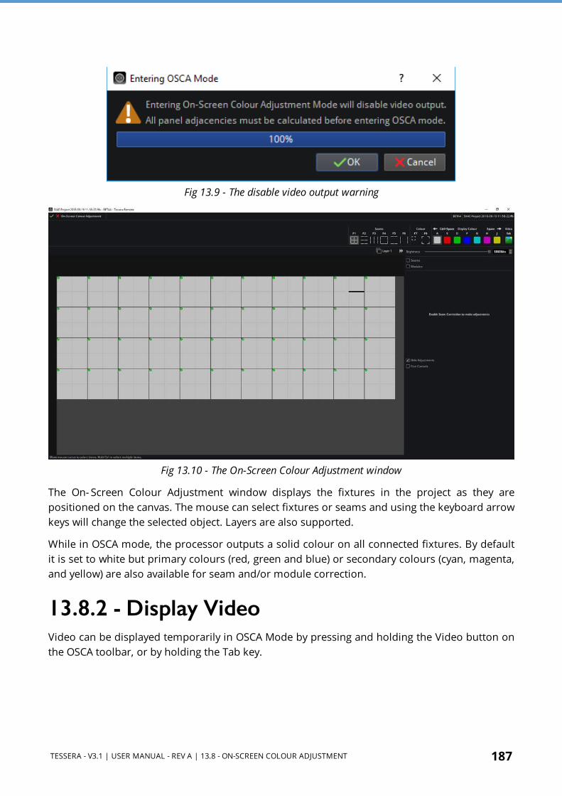
TESSERA - V3.1 | USER MANUAL - REV A | 13.8 - ON-SCREEN COLOUR ADJUSTMENT 187
Fig 13.9 - The disable video output warning
Fig 13.10 - The On-Screen Colour Adjustment window
The On- Screen Colour Adjustment window displays the fixtures in the project as they are positioned on the canvas. The mouse can select fixtures or seams and using the keyboard arrow keys will change the selected object. Layers are also supported.
While in OSCA mode, the processor outputs a solid colour on all connected fixtures. By default it is set to white but primary colours (red, green and blue) or secondary colours (cyan, magenta, and yellow) are also available for seam and/or module correction.
13.8.2 - Display VideoVideo can be displayed temporarily in OSCA Mode by pressing and holding the Video button on the OSCA toolbar, or by holding the Tab key.

188 TESSERA - V3.1 | USER MANUAL - REV A | 13.8 - ON-SCREEN COLOUR ADJUSTMENT
Fig 13.11 - The Video button on the OSCA toolbar, click or alternatively press Tab on the keyboard.
OSCA works in one of two modes: Seam Adjustment, which allows the luminance adjustment of fixtures and fixture modules, or Colour Adjustment which allows colour adjustment of fixtures or fixture modules. See Seams Adjustment on page 189 for more information.
13.8.3 - Display ColourChanging the colour displayed on the fixtures can help to assess differences in seam luminance, or colour variances between fixtures. The colour can be changed by selecting the colour from the OSCA toolbar or using the keyboard shortcut Space or Ctrl+Space to cycle through the different colours. Pressing the shortcuts keys as marked above the colour pattern buttons will also display the desired colour on screen.
Fig 13.12 - The Display Colour section of the OSCA toolbar
Adjustments can be made to white, primary and secondary colours.
When in colour correction mode, the controls only adjust the Master colour of the fixtures and/or the colour of the test pattern being used
Brightness SliderOSCA adjustments are performed in the On- Screen Colour Adjustment window. There is a Brightness slider and spin-box to adjust overall the brightness of selected fixtures or modules in Nits.
13.8.4 - Seams and Modules CheckboxThe Seams and Modules checkboxes enable or disable the OSCA modifications and allow for adjustments to be made to the fixtures. To access the modification options, the checkboxes need to be enabled.

TESSERA - V3.1 | USER MANUAL - REV A | 13.8 - ON-SCREEN COLOUR ADJUSTMENT 189
Seams Adjustment
Fig 13.13 - OSCA Seam adjustments
Due to mechanical design tolerances, many higher pixel pitch fixtures have issues lining up precisely with adjacent fixtures or can even have slight mechanical misalignment issues between the LED modules that make up the fixture. This can give rise to the appearance of perceived bright or dark lines at the seams of fixtures or modules that is noticeable when viewing certain content.
Seam adjustments allows the user to correct luminance at the seams between fixtures or between adjacent modules within fixtures.
Fixture or module seams can be selected in several different methods. Different seams can be selected by clicking on the relevant seam type on the OSCA toolbar.
Button Function Shortcut key
All modules seams selection F1
Modules horizontal seams selection F2
Modules vertical seams selection F3
Panel all seams selection F4
Panel horizontal seams selection F5
Panel vertical seams selection F6
Multiple seams can be selected by using Ctrl+click or click and drag the left mouse button to create a selection box around the seams.

190 TESSERA - V3.1 | USER MANUAL - REV A | 13.8 - ON-SCREEN COLOUR ADJUSTMENT
Fig 13.14 - Different seam selection methods
When seams are selected on the OSCA canvas, the relevant seams are highlighted on the physical fixtures.
Fig 13.15 - OSCA on fixtures showing selected seams and cursor
Once seams have been selected, luminance can be adjusted by:

TESSERA - V3.1 | USER MANUAL - REV A | 13.8 - ON-SCREEN COLOUR ADJUSTMENT 191
1. Pressing and holding the 1 key and use either the + and – keys or the up and down arrows on the keyboard to increase or decrease luminance.
2. Click and drag with the mouse over the blue and white Luminance thumbwheel. 3. Hover the mouse pointer over the Luminance thumbwheel and use the mouse scroll
wheel to scroll up or down to adjust.
Fig 13.16 - Seam Brightness Correction property editor, displaying luminance thumbwheel
The Seam Brightness Control panel features a Layers selection. Currently displayed layers are checked, to 'hide' layers, uncheck the corresponding check-box. Hidden layers do not output whilst in OSCA Mode. See Layers on page 119 for more information.
l Hide adjustments: When adjustments are being made, the selection is hidden for a better view of the modifications. Disable this option to keep the selection always active.
l Fine controls: Enabling Fine controls gives the user the finest amount of control, a single key press adjusts to give the smallest change possible compared to the default mode where changes are substantial. Alternatively, press and hold the Ctrl key while using Fine Control.
l Reset: The Reset button under the Luminance thumbwheel allows the original luminance value to be restored.

192 TESSERA - V3.1 | USER MANUAL - REV A | 13.8 - ON-SCREEN COLOUR ADJUSTMENT
Colour AdjustmentOccasionally when using different batches of the same LED fixtures together the LEDs may have aged differently, or the fixtures may have slightly different calibrations. Colour Adjustment offers 7- way colour correction to quickly match fixtures which appear to have different in colours or brightnesses.
NOTE OSCA adjustments do not overwrite existing fixture colour calibrations. OSCA is a fixture-based adjustment and OSCA values are stored within the fixture. This means the adjustments travel with the panels themselves, so if a LED wall is re-assembled from fixtures in a different order, the OSCA adjustments can be used with the new fixture order.
To adjust colour for selected modules, select the Module icon or press F7. For fixtures, press F8 or select the Fixture icon on the OSCA toolbar.
Fig 13.17 - Icons for selecting module or fixture Colour Adjustment on the OSCA toolbar
The following figures show a selection of fixtures or modules respectively:
Fig 13.18 - The canvas showing module selection mode for Colour Adjustment

TESSERA - V3.1 | USER MANUAL - REV A | 13.8 - ON-SCREEN COLOUR ADJUSTMENT 193
Fig 13.19 - The canvas in fixture selection mode for Colour Adjustment
Once modules or fixtures colour correction is selected, the Colour Adjustment panel is shown. The properties can be adjusted:
1. Press hold the shortcut key and use in conjunction with the + and - keys or the up and down arrows to increase and decrease values.
2. Click and drag with the mouse over the thumbwheel. 3. Hover the mouse pointer over the thumbwheel and use the mouse scroll wheel.
The shortcuts will only affect the selected colour. Selecting a colour offers the following settings:
Master Colour (affects all colours) Shortcut Key
Luminance 1
Red Gain 2
Green Gain 3
Blue Gain 4
Selected Colour (white) Shortcut Key
Luminance Q
Red Gain W
Green Gain E
Blue Gain R
Selected colour (Primary or Secondary) Shortcut Key
Hue Q
Saturation W
Luminance E
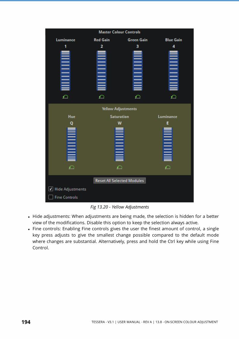
194 TESSERA - V3.1 | USER MANUAL - REV A | 13.8 - ON-SCREEN COLOUR ADJUSTMENT
Fig 13.20 - Yellow Adjustments
l Hide adjustments: When adjustments are being made, the selection is hidden for a better view of the modifications. Disable this option to keep the selection always active.
l Fine controls: Enabling Fine controls gives the user the finest amount of control, a single key press adjusts to give the smallest change possible compared to the default mode where changes are substantial. Alternatively, press and hold the Ctrl key while using Fine Control.
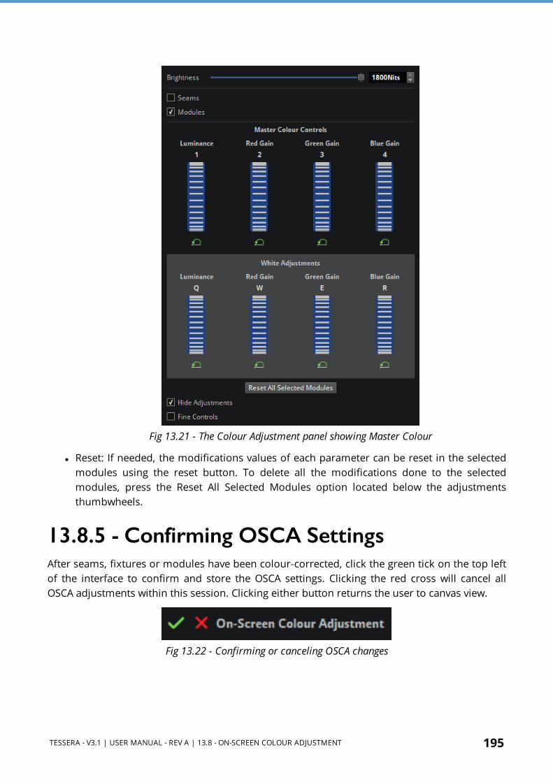
TESSERA - V3.1 | USER MANUAL - REV A | 13.8 - ON-SCREEN COLOUR ADJUSTMENT 195
Fig 13.21 - The Colour Adjustment panel showing Master Colour
l Reset: If needed, the modifications values of each parameter can be reset in the selected modules using the reset button. To delete all the modifications done to the selected modules, press the Reset All Selected Modules option located below the adjustments thumbwheels.
13.8.5 - Confirming OSCA Settings After seams, fixtures or modules have been colour-corrected, click the green tick on the top left of the interface to confirm and store the OSCA settings. Clicking the red cross will cancel all OSCA adjustments within this session. Clicking either button returns the user to canvas view.
Fig 13.22 - Confirming or canceling OSCA changes

196 TESSERA - V3.1 | USER MANUAL - REV A | 13.8 - ON-SCREEN COLOUR ADJUSTMENT
Copying and Pasting OSCA SettingsCopy: OSCA settings can only be copied from a single module, copying from multiple modules is not supported. In OSCA mode, select a single module, right-click and select Copy OSCA colour settings.
Paste: Settings can be pasted to single or multiple modules simultaneously.
1. Select multiple modules by holding Ctrl. 2. Once selection is complete right-click one of the selected modules. 3. Click Paste OSCA colour settings to apply copied values to all selected modules.
When pasting OSCA settings, all the OSCA colour settings will be overwritten. OSCA seam adjustments are not affected.
If using Tessera Remote, it is possible to copy OSCA colour settings from one processor to another. From processor 1, copy the OSCA colour settings and paste them to connected fixtures in the OSCA window of processor 2.
Importing and Exporting OSCA Settings
Export: 1. In OSCA mode, select a single fixture and right-click it. 2. Select Export OSCA colour settings. 3. Select a location to export the data (e.g. USB storage), and the colour adjustments will be
written to a file.
Import: 1. Select the target modules (on the same, or a different processor) and right-click. 2. Select Import OSCA colour settings. 3. Select the previously-exported file. The colour adjustments will be read from the file and
sent to all selected modules.
As with copy and paste, colour settings for all colours will be overwritten, regardless of which colour is currently used. OSCA seam adjustments are not affected.

TESSERA - V3.1 | USER MANUAL - REV A | 13.8 - ON-SCREEN COLOUR ADJUSTMENT 197
13.8.6 - OSCA Keyboard Shortcuts
General OSCA ShortcutsFunction Shortcut Key
Seam selection mode F1 - F6
Module Colour Adjustment F7
Fixture Colour Adjustment F8
Display white A
Display Red S
Display Green D
Display Blue F
Display Cyan G
Display Magenta H
Display Yellow J
Display Video Tab
Change Display Colour forwards Space
Change Display Colour backwards Ctrl+Space
OSCA Colour and Luminance AdjustmentsFunction Shortcut Key
Luminance Adjustment 1
Red Gain 2
Green Gain 3
Blue Gain 4
increase/decrease parameter Click+Scroll Wheel
Hue Q
Saturation W
Luminance E
Decrease parameter -
Increase parameter +
Fine Adjustment Ctrl+parameter shortcut

198 TESSERA - V3.1 | USER MANUAL - REV A | 13.8 - ON-SCREEN COLOUR ADJUSTMENT
White AdjustmentFunction Shortcut Key
Luminance Adjustment Q
Red Gain W
Green Gain E
Blue Gain R
Red, Green, Blue, Cyan, Magenta and Yellow Adjustment
Function Shortcut Key
Red Gain Q
Green Gain W
Blue Gain E
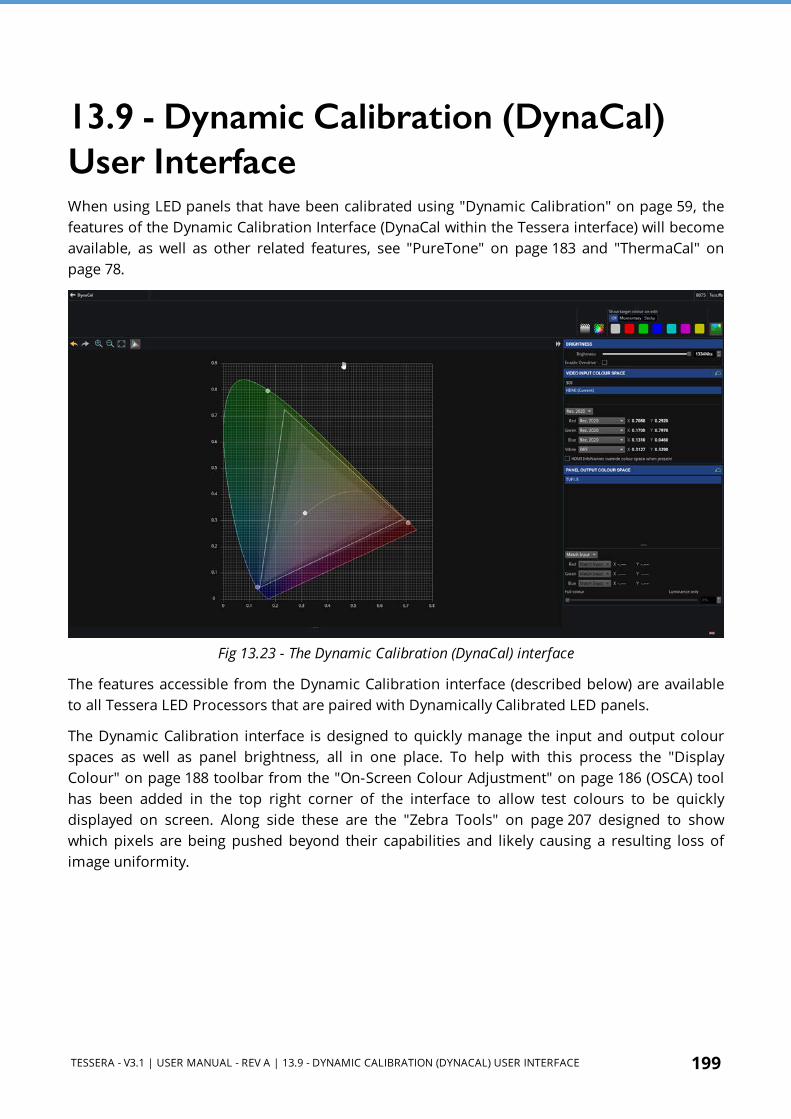
TESSERA - V3.1 | USER MANUAL - REV A | 13.9 - DYNAMIC CALIBRATION (DYNACAL) USER INTERFACE 199
13.9 - Dynamic Calibration (DynaCal) User InterfaceWhen using LED panels that have been calibrated using "Dynamic Calibration" on page 59, the features of the Dynamic Calibration Interface (DynaCal within the Tessera interface) will become available, as well as other related features, see "PureTone" on page 183 and "ThermaCal" on page 78.
Fig 13.23 - The Dynamic Calibration (DynaCal) interface
The features accessible from the Dynamic Calibration interface (described below) are available to all Tessera LED Processors that are paired with Dynamically Calibrated LED panels.
The Dynamic Calibration interface is designed to quickly manage the input and output colour spaces as well as panel brightness, all in one place. To help with this process the "Display Colour" on page 188 toolbar from the "On-Screen Colour Adjustment" on page 186 (OSCA) tool has been added in the top right corner of the interface to allow test colours to be quickly displayed on screen. Along side these are the "Zebra Tools" on page 207 designed to show which pixels are being pushed beyond their capabilities and likely causing a resulting loss of image uniformity.

200 TESSERA - V3.1 | USER MANUAL - REV A | 13.9 - DYNAMIC CALIBRATION (DYNACAL) USER INTERFACE
13.9.1 - Accessing the Dynamic Calibration (DynaCal) Interface
Fig 13.24 - Accessing the DynaCal interface
The Dynamic Calibration interface (DynaCal) can be accessed in four different ways within the Tessera UI:
1. From the Tools menu under DynaCal. 2. Using the shortcut CTRL + SHIFT + D. 3. By clicking the DynaCal button within the "Input Override" on page 142 controls shown
after clicking any Input. 4. By clicking the DynaCal button at the bottom of the "Global Colour" on page 178
property editor.
13.9.2 - Brightness and Brightness OverdriveThe Brightness panel offers a slider to control the output brightness of all connected LED panels. When multiple panels, with different brightness ratings are connected to the LED Processor, the slider will show markings along its length matching the calibrated brightness for each panel type.
Fig 13.25 - Calibration brightness markings (blue arrows) for different LED panels

TESSERA - V3.1 | USER MANUAL - REV A | 13.9 - DYNAMIC CALIBRATION (DYNACAL) USER INTERFACE 201
The markings assist visually when making decisions about the required brightness. Setting the brightness to the lowest marker is recommended when uniformity is paramount as it will mean all panels will operate either at or below their calibrated brightness rather than over which could introduce visual artefacts should the LEDs within the panels be pushed to their brightness limits.
It is possible to drive the brightness beyond the calibrated brightness of each panel by checking the Enable Overdrive box. This will change the scale of the brightness slider (see "Enabling Brightness Overdrive changes the brightness slider cap" below), which by default is capped to the value of the panel with the highest calibrated brightness.
Fig 13.26 - Enabling Brightness Overdrive changes the brightness slider cap
Once overdrive has been enabled the slider will allow the brightness of the panels to be pushed to the brightness limit of the LEDs within the panels. This will come at the expense of uniformity and as the brightness is pushed far beyond the capabilities of most LEDs within the panel the image will appear speckled, though brighter.
To help identify the pixels that are being pushed beyond their brightness capabilities the brightness "Zebra Tools" on page 207 can be enabled.
IMPORTANT The Brightness Overdrive feature does not drive the LED panels any harder than if they were being operated in uncalibrated mode and does not change the voltage being passed through the LEDs. Please use the same precautions you would when running your panels uncalibrated when pushing the brightness much higher than the panels' calibrated brightness.

202 TESSERA - V3.1 | USER MANUAL - REV A | 13.9 - DYNAMIC CALIBRATION (DYNACAL) USER INTERFACE
13.9.3 - Video Input Colour Space
Fig 13.27 - Video Input Colour Space controls on a Tessera SX40
The Video Input Colour Space controls are used to specify the colour space of the incoming video whereas the "Panel Output Colour Space" on the facing page controls are used to define what colour space the output should use. Provided the correct colour space is given for the incoming content, the Tessera LED Processor will translate the colours onto the output colour space correctly.
At the top of the Video Input Colour Space controls are the available inputs. To change the colour space for a given input left click to select it, once it is highlighted (like HDMI in "Video Input Colour Space controls on a Tessera SX40" above) both colour space controls at the bottom will become active. If multiple inputs are selected changes made to the Video Input Colour Space will be applied to all of them.
NOTE Multiple inputs can be selected at the same time by either:
l Holding left click on one input and dragging the cursor over the other inputs. l Holding CTRL and clicking individual inputs to either select or deselect them.
NOTE If the HDMI InfoFrames override colour space when present checkbox has been ticked this will not allow changes to be made to the HDMI input's colour space. This will also prevent other Video Input Colour Spaces from being editable if the HDMI input is selected with them (and the checkbox has been ticked).

TESSERA - V3.1 | USER MANUAL - REV A | 13.9 - DYNAMIC CALIBRATION (DYNACAL) USER INTERFACE 203
Fig 13.28 - Available input colour space presets
The system has 3 presets for the most common colour spaces:
l Rec.2020 l DCI-P3 l Rec.709
Using the drop-down menu the colour space can be quickly switched between the 3 presets. If custom is selected this unlocks the colour space graph and allows direct editing of the RGBW targets. See Customising Colour Spaces on page 209 for more information.
13.9.4 - Panel Output Colour Space
Fig 13.29 - Panel Output Colour Space controls
The Panel Output Colour Space controls are used to specify the colour space used to display the incoming content on the LED panels. Like for the "Video Input Colour Space" on the previous page at the top of the Panel Output Colour Space is a list of all the connected panels. Each panel can have a different definition for the output colour space. If the same content is playing across all panels it is recommended that all panels use the same output colour space.
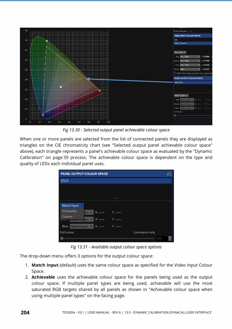
204 TESSERA - V3.1 | USER MANUAL - REV A | 13.9 - DYNAMIC CALIBRATION (DYNACAL) USER INTERFACE
Fig 13.30 - Selected output panel achievable colour space
When one or more panels are selected from the list of connected panels they are displayed as triangles on the CIE chromaticity chart (see "Selected output panel achievable colour space" above), each triangle represents a panel's achievable colour space as evaluated by the "Dynamic Calibration" on page 59 process. The achievable colour space is dependent on the type and quality of LEDs each individual panel uses.
Fig 13.31 - Available output colour space options
The drop-down menu offers 3 options for the output colour space:
1. Match Input (default) uses the same colour space as specified for the Video Input Colour Space.
2. Achievable uses the achievable colour space for the panels being used as the output colour space. If multiple panel types are being used, achievable will use the most saturated RGB targets shared by all panels as shown in "Achievable colour space when using multiple panel types" on the facing page.

TESSERA - V3.1 | USER MANUAL - REV A | 13.9 - DYNAMIC CALIBRATION (DYNACAL) USER INTERFACE 205
3. Custom allows the user to specify a custom output colour space. See Customising Colour Spaces on page 209 for more information.
Fig 13.32 - Achievable colour space when using multiple panel types
Match Input Versus AchievableWhenever the Panel Output Colour Space is greater than the achievable colour space for the connected panels, then the colour space is intelligently scaled by the Tessera LED Processor to fit within the achievable colour space for all the panels. This is what will typically happen when using the Match Input setting with an input using the Rec.2020 colour space; panel LEDs cannot yet fully cover the entire Rec.2020 colour space.
If the Panel Output Colour Space is set to Achievable, square RGB targets will appear on the CIE chromaticity chart at the most saturated RGB coordinates shared by all connected panels. Colours outside the triangle formed by the square RGB targets will be clipped to the nearest achievable colour by the panels as they cannot be reproduced by the panels.
The difference between the two examples above will typically be small because LEDs are close to being able to represent the full colour gamut for the Rec.2020 colour spaces, so the difference between how Match Input and Achievable behave will be small. The main difference between using Match Input and Achievable is that when using Match Input the Tessera LED Processor better represents the colour contrast of each frame since it intelligently scales the input colour space onto the achievable output colour space. Instead, when using Achievable the colours of the input colour space that are outside the achievable colour space (for the panels being used) are simply clipped to the nearest achievable colour for the panels, thereby losing a bit of contrast in the image.
For the best results it is therefore recommended to leave the Panel Output Colour Space set to Match Input.

206 TESSERA - V3.1 | USER MANUAL - REV A | 13.9 - DYNAMIC CALIBRATION (DYNACAL) USER INTERFACE
13.9.5 - DynaCal Colour Toolbar
Fig 13.33 - DynaCal Colour Toolbar
In the top right corner of the DynaCal interface is the DynaCal Colour Toolbar. This is a combination of the OSCA "Display Colour" on page 188 controls as well as the new "Zebra Tools" on the facing page to the left.
The "Display Colour" on page 188 controls operate in much the same way as for OSCA:
l When any of the white, primary, or secondary colour buttons is pressed, the screen will display that test colour.
l Clicking a different colour will display that colour instead. l Return to showing the incoming content by either clicking the already selected test colour
(which will be highlighted), or the Show Video button.
NOTE Test colours will not appear on-screen if the image is frozen. See Freeze/Blackout on page 176 for more information.
The Show target colour on edit option adds an extra layer of functionality:
1. Momentary will show the primary test colour (on screen) associated with either the input (round) or output (square) colour target that is being held/moved with a continuous left mouse button press. Once the colour target is released the screen will stop showing the associated test colour.
2. Sticky will show the primary test colour (on screen) associated with either the input (round) or output (square) colour target that was last selected with a left mouse click. The test colour will remain on screen until either another colour target or test colour is selected, or until the test colour is deselected from the DynaCal Colour Toolbar, or until the Show Video button is pressed.
NOTE The Show target colour on edit feature will only show test colours for the RGB input (round) and output (square) colour targets, not the white.
IMPORTANT All test colours that are shown on screen are dependent on the Panel Output Colour Space and will look different depending on whether the Panel Output Colour Space has been set to Full colour, or Luminance only. See Full Colour and Luminance Only Calibration on page 208 for more information.

TESSERA - V3.1 | USER MANUAL - REV A | 13.9 - DYNAMIC CALIBRATION (DYNACAL) USER INTERFACE 207
Zebra ToolsDynamic Calibration allows much more control over the colour and brightness output of LED panels. Depending on the achievable "Panel Output Colour Space" on page 203 and whether or not the Brightness Overdrive (page 200) is being used, the LED panels can be pushed beyond their limits.
Fig 13.34 - Zebra Tools: Overbright pixels (left) Out-of-gamut pixels (right)
The Zebra Tools are designed for highlighting both Overbright and Out-of-gamut pixels. Both tools can be enabled / disabled from the DynaCal Interface as well as from the "Global Colour" on page 178 panel.
Fig 13.35 - Button to enable / disable Zebra Tools from the Global Colour panel
To enable either simply click the desired Zebra Tool button, likewise to disable any that is turned on. Once either Zebra Tool has been enabled, an animated striped (zebra) pattern will show on LED panels over the pixels that have been pushed beyond their limits.
Each Zebra Tool has a distinct direction to the striped (zebra) pattern, also reflected in their logos. The Overbright pixel Zebra Tool will show (zebra) stripes oriented diagonally from top left to bottom right, whereas the Out-of-gamut pixel Zebra Tool will show (zebra) stripes oriented diagonally from top right to bottom left, use "Recognising Overbright (left) and Out-of-gamut (right) Zebra Tool patterns" on the next page for reference.
NOTE Both Zebra Tools can be active in the same area and will show overlapping animated striped patterns.
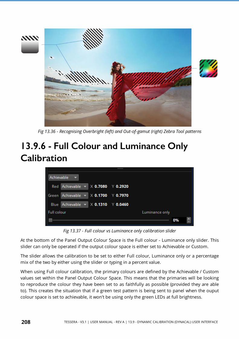
208 TESSERA - V3.1 | USER MANUAL - REV A | 13.9 - DYNAMIC CALIBRATION (DYNACAL) USER INTERFACE
Fig 13.36 - Recognising Overbright (left) and Out-of-gamut (right) Zebra Tool patterns
13.9.6 - Full Colour and Luminance Only Calibration
Fig 13.37 - Full colour vs Luminance only calibration slider
At the bottom of the Panel Output Colour Space is the Full colour - Luminance only slider. This slider can only be operated if the output colour space is either set to Achievable or Custom.
The slider allows the calibration to be set to either Full colour, Luminance only or a percentage mix of the two by either using the slider or typing in a percent value.
When using Full colour calibration, the primary colours are defined by the Achievable / Custom values set within the Panel Output Colour Space. This means that the primaries will be looking to reproduce the colour they have been set to as faithfully as possible (provided they are able to). This creates the situation that if a green test pattern is being sent to panel when the ouput colour space is set to achievable, it won't be using only the green LEDs at full brightness.
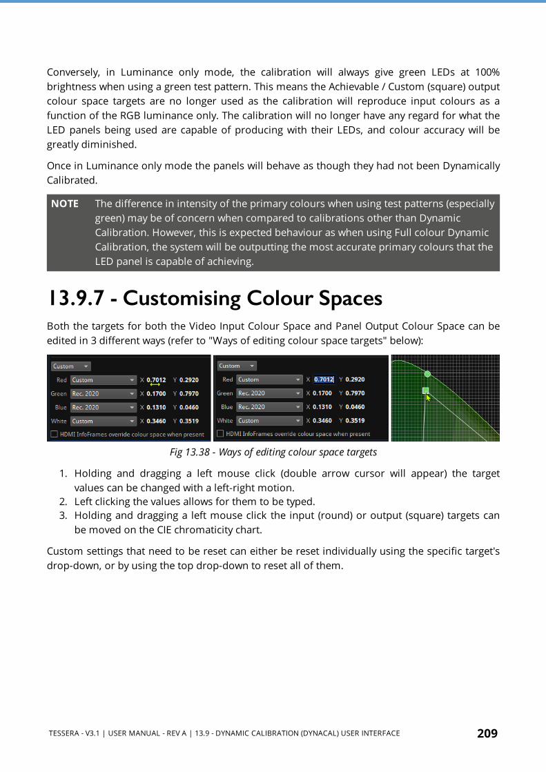
TESSERA - V3.1 | USER MANUAL - REV A | 13.9 - DYNAMIC CALIBRATION (DYNACAL) USER INTERFACE 209
Conversely, in Luminance only mode, the calibration will always give green LEDs at 100% brightness when using a green test pattern. This means the Achievable / Custom (square) output colour space targets are no longer used as the calibration will reproduce input colours as a function of the RGB luminance only. The calibration will no longer have any regard for what the LED panels being used are capable of producing with their LEDs, and colour accuracy will be greatly diminished.
Once in Luminance only mode the panels will behave as though they had not been Dynamically Calibrated.
NOTE The difference in intensity of the primary colours when using test patterns (especially green) may be of concern when compared to calibrations other than Dynamic Calibration. However, this is expected behaviour as when using Full colour Dynamic Calibration, the system will be outputting the most accurate primary colours that the LED panel is capable of achieving.
13.9.7 - Customising Colour SpacesBoth the targets for both the Video Input Colour Space and Panel Output Colour Space can be edited in 3 different ways (refer to "Ways of editing colour space targets" below):
Fig 13.38 - Ways of editing colour space targets
1. Holding and dragging a left mouse click (double arrow cursor will appear) the target values can be changed with a left-right motion.
2. Left clicking the values allows for them to be typed. 3. Holding and dragging a left mouse click the input (round) or output (square) targets can
be moved on the CIE chromaticity chart.
Custom settings that need to be reset can either be reset individually using the specific target's drop-down, or by using the top drop-down to reset all of them.

210 TESSERA - V3.1 | USER MANUAL - REV A | 13.9 - DYNAMIC CALIBRATION (DYNACAL) USER INTERFACE
Customising the White Point
Fig 13.39 - Editing white point as a colour temperature
The White-point target for the Video Input Colour Space can be changed either to a completely custom value, or a Colour Temperature value. When set to Colour Temperature from the drop-down menu (as shown in "Editing white point as a colour temperature" above) the white colour target will be locked to the colour temperature arc and can take any value from 2000 K to 11,000 K.
NOTE The Video Input Colour Space white point value is not related to the "Colour Temperature" on page 179 in the "Global Colour" on page 178 panel, even when set to Colour Temperature. The two effects will work additively. If the Colour Temperature is to be edited it is recommended to use the "Global Colour" on page 178 setting as the Video Input Colour Space white point should match the white point used to create the incoming video content.
Fig 13.40 - Custom white point target out of bounds
The White point target can be anywhere within the Panel Output Colour Space. If it is brought out-of-bounds the UI will indicate the closest colour within the output colour space to which the out-of-bounds white point is being mapped (see "Custom white point target out of bounds"

TESSERA - V3.1 | USER MANUAL - REV A | 13.9 - DYNAMIC CALIBRATION (DYNACAL) USER INTERFACE 211
above). The indicator will show two intercept points, the first on the Video Input Colour Space and the second on the Panel Output Colour Space.
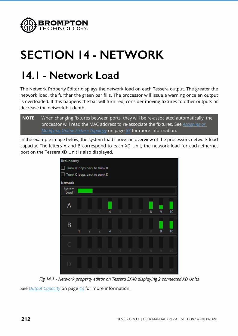
212 TESSERA - V3.1 | USER MANUAL - REV A | SECTION 14 - NETWORK
SECTION 14 - NETWORK
14.1 - Network LoadThe Network Property Editor displays the network load on each Tessera output. The greater the network load, the further the green bar fills. The processor will issue a warning once an output is overloaded. If this happens the bar will turn red, consider moving fixtures to other outputs or decrease the network bit depth.
NOTE When changing fixtures between ports, they will be re-associated automatically, the processor will read the MAC address to re-associate the fixtures. See Assigning or Modifying Online Fixture Topology on page 87 for more information.
In the example image below, the system load shows an overview of the processors network load capacity. The letters A and B correspond to each XD Unit, the network load for each ethernet port on the Tessera XD Unit is also displayed.
Fig 14.1 - Network property editor on Tessera SX40 displaying 2 connected XD Units
See Output Capacity on page 43 for more information.
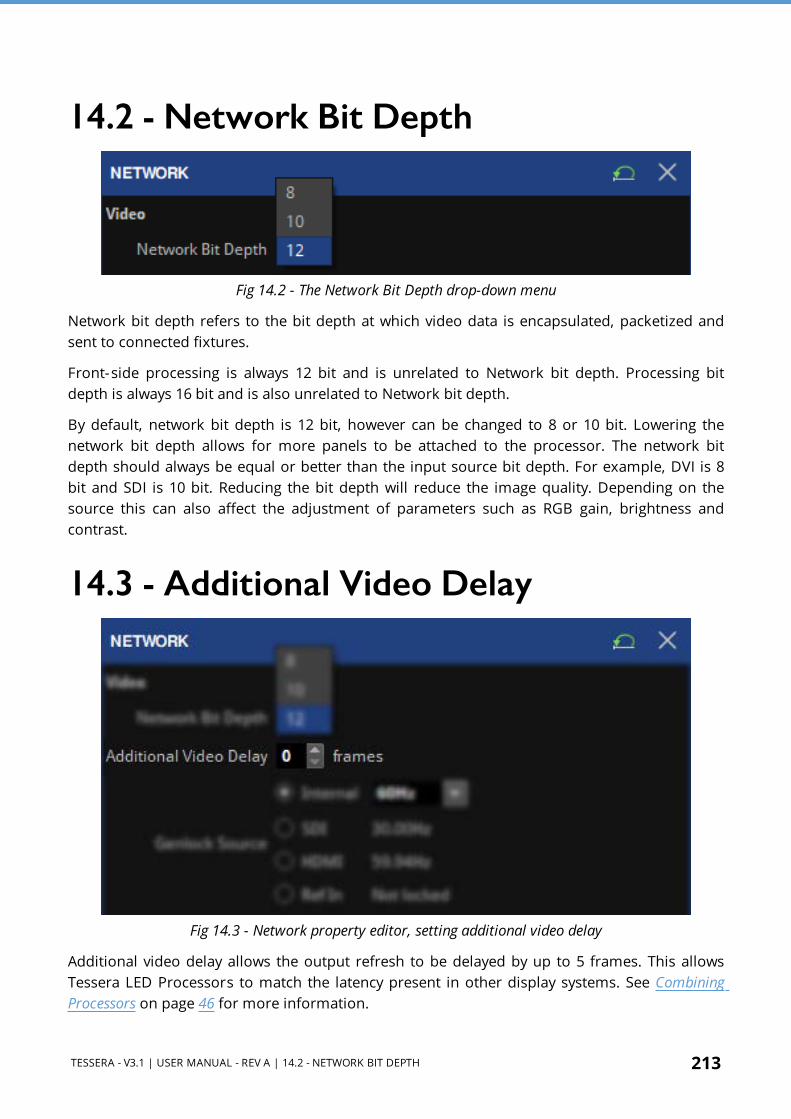
TESSERA - V3.1 | USER MANUAL - REV A | 14.2 - NETWORK BIT DEPTH 213
14.2 - Network Bit Depth
Fig 14.2 - The Network Bit Depth drop-down menu
Network bit depth refers to the bit depth at which video data is encapsulated, packetized and sent to connected fixtures.
Front-side processing is always 12 bit and is unrelated to Network bit depth. Processing bit depth is always 16 bit and is also unrelated to Network bit depth.
By default, network bit depth is 12 bit, however can be changed to 8 or 10 bit. Lowering the network bit depth allows for more panels to be attached to the processor. The network bit depth should always be equal or better than the input source bit depth. For example, DVI is 8 bit and SDI is 10 bit. Reducing the bit depth will reduce the image quality. Depending on the source this can also affect the adjustment of parameters such as RGB gain, brightness and contrast.
14.3 - Additional Video Delay
Fig 14.3 - Network property editor, setting additional video delay
Additional video delay allows the output refresh to be delayed by up to 5 frames. This allows Tessera LED Processors to match the latency present in other display systems. See Combining Processors on page 46 for more information.

214 TESSERA - V3.1 | USER MANUAL - REV A | 14.4 - GENLOCK SETTINGS
14.4 - Genlock Settings
Fig 14.4 - Genlock Settings on the Network property editor.
Without genlock, screens may appear to have dark lines rolling up or down the screen when viewed on camera. Tessera processors include genlocking which ties the camera and the screen together to stop these dark lines from moving, but in some cases they may still be visible.
14.4.1 - InternalThe internal setting allows an overall refresh rate for the processor to work from 23.98 up to 60 fps. Irrespective of the input source frame rate. The processor will automatically compensate where the source frame rate and the internal refresh rates are different.
14.4.2 - Reference InTessera SX40, S8, and M2 LED Processors can synchronise their system and panel refresh to an external bi-level or tri-level reference. The processor will automatically compensate for sources that do not match the refresh rate of the external reference. The external reference can also be another Tessera LED Processor with a source connected.
14.4.3 - Locking to Video InputsTessera LED Processors can lock their refresh rate to the incoming source, regardless of the inputs. The processor will automatically compensate for sources that do not match the selected source refresh rate.

TESSERA - V3.1 | USER MANUAL - REV A | 14.4 - GENLOCK SETTINGS 215
NOTE The selected genlock frame rate affects the capacity of each Tessera output port. See Output Capacity on page 43 for more information.
If the frame rate of the video input differs from the reference, whether it is internal, another video input or a bi- level or tri- level sync, the processor will match the frame rate by either doubling or dropping frames. For critical synchronisation between two or more processors, the incoming frame rate should match the referenced frame rate.
14.4.4 - Active Input GenlockThe ‘Active Input’ is selected by default for new projects and switches automatically to the genlock source between the HDMI and SDI inputs according to which input is selected as the active video source. This helps to display video content at the correct frame rate with the minimum latency and avoids frame drops or doubling due to inadvertently using the wrong genlock source.
NOTE This is a Tessera SX40 and S8 only feature as Tessera S4 and T1 have only one input, and the M2 has two video processing pipelines and can crossfade between inputs, so dynamically switching the genlock source on these processors is not as desirable.
14.4.5 - Genlock Phase OffsetGenlock Phase Offset permits fine control of the LED screen timing to rectify visual artefacts if present on camera. Artefacts which may appear as dark lines on the LED wall when viewed through the camera's electronic viewfinder. Settings should be toggled until less apparent or in cases completely disappear off the top or bottom of the camera frame.
NOTE Fine control of camera shutter speed is typically also required to avoid scan multiplexing causing artefacts on camera. I.e. Fine shutter speed control on the camera is also needed alongside genlock phase offset on the processor to achieve the best possible results.
Phase Offset slightly adjusts the timing (phase) of when video frames are displayed on the panels relative to the selected genlock source. This allows the output to be delayed by a fraction of a frame. Fraction, Angle and Absolute are three different ways of specifying this delay.
Fig 14.5 - Phase Offset options can be found under Network, Genlock. Options available to offset by are angle, fraction or use an absolute value.

216 TESSERA - V3.1 | USER MANUAL - REV A | 14.4 - GENLOCK SETTINGS
Fraction: This specifies the desired delay as a proportion of the genlock source's frame period. For example, with a 60Hz genlock source, a fraction of 50% corresponds to 1/120th of a second.
Angle: Instead of specifying the fraction as a range between 0% and 100%, this is specified as an angle relative to a full circle, i.e. from 0° to 360°. Thus, with a 60Hz genlock source, an angle of 180° corresponds to 1/120th of a second.
Absolute: This permits the delay to be specified in terms of lines and pixels. For example, for a 1920 x 1080 genlock signal, a delay of 540 lines corresponds to approximately half a frame.
These delays can be specified as positive or negative values. Using a negative value adjusts the sync point by adding latency to the incoming video signal. For example, a Phase Offset of -10% delays the incoming video frames by 10% of a frame period.
14.4.6 - Frame Rate MultiplicationIt is now possible to multiply the incoming genlock signal by a factor between x2 and x10.
For example: if recording from a camera at 30fps, the genlock signal will likely be 30Hz, but the content may be 60fps for smoother movement. By multiplying the genlock signal x2, the LED fixtures can run at 60fps while still maintaining genlock. This achieves the best possible combination of good on-camera performance (due to genlock) as well as smooth motion when viewed by eye (due to running at 60fps rather than 30fps).
This can also be used in combination with High frame rate support; e.g. to convert a 24Hz genlock signal to 144Hz by applying a factor of x6.
Maximum output frame rate is processor dependent (i.e. 250Hz on Tessera SX40 and S8, 60Hz on HD processors).
Fig 14.6 - An example of frame rate multiplication, the default refresh rate is taken from the source input and the output frame rate is multiplied simply by selecting an option.

TESSERA - V3.1 | USER MANUAL - REV A | 14.4 - GENLOCK SETTINGS 217
14.4.7 - Frame RemappingFrame Remapping allows the user to interleave different areas of the incoming video raster or solid colours into the output displayed on the LED panels.
At its most simple Frame Remapping allows the output frame rate to be doubled so that a black frame can be inserted between every frame of actual content – a useful technique for reducing motion blur. Enabling Frame Rate Multiplication will now enable each of the (up to x10) output frames to be configured to display either video content or a solid colour.
For example; to interleave a black frame with each frame of the incoming video, set the Multiplier to 2, and set the relevant output frame to Colour. By default this is black.
Fig 14.7 - Example of the Multiplier set to 2.
Clicking on the colour chip opens a colour picker that allows any 24-bit colour to be chosen, either using the colour picker itself, which can be set to RGB or CMY modes or by entering the desired RGB (or CMY) or HSI values.
Fig 14.8 - Example of how to select alternative colours.
For example; if you wanted to interleave a video input with two different points of view, and a green field for green screen in a virtual production application, you could use a x3 multiplier with the first two frames of the sequence using different parts of the incoming raster, and the third frame of the sequence being a green field. In this example we are using a 3840 x 1080

218 TESSERA - V3.1 | USER MANUAL - REV A | 14.4 - GENLOCK SETTINGS
video input at 60Hz. The first frame is using a 1920 x 1080 section from the incoming raster from x = 0, y = 0. The second frame is using a 1920 x 1080 section from x = 1920, y = 0. With the third frame, we select the colour tab and select the correct shade of green from the colour picker.
The frame in the sequence of three frames is appearing 60 times a second, and having three frames in sequence gives us an output frame rate of 180Hz, which is shown in the Frame Multiplication user interface.
Frame 1 Frame 2 Frame 3
Sequential
1920 x 1080 Interleaved Frames
LED Screen @ 180Hz
3840 x 1080 @ 60Hz
HDMI 2.0 Source
Fig 14.9 - Example of the Multiplier set to 3.
IMPORTANT Frame Remapping could be used to create flashing or flickering effects, with potential to cause disorientation or discomfort, or to be a risk factor for photosensitive epilepsy.

TESSERA - V3.1 | USER MANUAL - REV A | 14.5 - ULTRA LOW LATENCY 219
14.5 - Ultra Low LatencyThe latency of the Tessera SX40 and Tessera S8 LED Processors is currently an industry-leading 2 frames end-to-end (including the driver chip latency and with all processor features enabled, including scaling). For broadcast applications such as virtual studios and film- industry applications, visual effects and virtual sets, latency minimisation can be considered critical.
From Tessera version 2.3 onwards Ultra Low Latency mode is available for the Tessera SX40 and Tessera S8 LED Processors. Using this feature reduces the end-to-end latency to 1 frame, at the expense of halving the system’s pixel capacity. (Video input pixel capacity and 1G output capacity are both halved. Tessera R2 Receiver Card pixel capacity remains unaffected.)
To achieve the reduction in latency, the processor and video source must work together. Typically, PC-based sources (such as media servers) which respect the processor’s EDID should be able to support ultra- low latency, while video production sources (such as cameras or production switchers) may ignore the EDID and therefore be incompatible with ultra-low latency mode. Overall, sources which do support ultra-low latency will be able to display content on the LEDs one frame earlier.
NOTE Ultra-low latency can also be used in conjunction with High frame rate.
E.g. A 60Hz system would normally have a latency of 2 x 1/60 = 33ms. A 120Hz system in ultra-low latency mode has a latency of just 1 x 1/120 = 8.3ms, albeit with a quarter of the original pixel capacity (halved due to operating at 120Hz, then halved again due to enabling ultra-low latency). If operating with media servers, more HDMI outputs and more processors are required!
NOTE Ultra-Low-Latency is a Tessera SX40 and S8 only feature, as the video inputs on Brompton HD processors don’t support ultra-low latency.
IMPORTANT It is recommended that any setup using the Ultra Low Latency is tested before going into a production environment as not all sources will be capable of outputting and / or adhering to our Tessera LED Processor EDID.

220 TESSERA - V3.1 | USER MANUAL - REV A | 14.6 - HFR+ (HIGH FRAME RATE)
14.6 - HFR+ (High Frame Rate)The Tessera SX40 and Tessera S8 LED Processors support up to 250 fps, this increase to frame rate allows for input content (if input is being sent at high frame rate) to appear smoother, or allows for more action-packed scenes to appear in more detail. This implementation is not without its trade-off between capacity and frame rates. Due to HDMI bandwidth limitations with the increase to frame rate, the processor video input pixel capacity is also reduced. SDI inputs do not support High Frame Rate.
For example, the Tessera SX40 processor capacity at 60Hz is approximately 9 million pixels. By doubling the frame rate to 120 Hz, this halves to 4.5 million pixels. At the maximum of 250 Hz, the capacity is 2.15 million pixels.
With the addition of High Frame Rate and the reduced pixel capacity, canvas properties supports additional resolutions and refresh rates for high frame rate: 3K (3072 x 1728) up to 100 Hz, 2.8K (2800 x 1575) up to 120 Hz, QHD (2560 x 1440) up to 144 Hz and HD (1920 x 1080) up to 144 Hz. It’s also possible to specify any custom resolution and refresh rate that remains within the pixel capacity limit. (This generates a custom EDID to help configure the source.)
1G output capacity also scales according to frame rate (e.g. 525,000 pixels at 8-bit 60Hz halves to 262,500 pixels at 8-bit 120 Hz). High frame rate requires high frame rate-capable Tessera R2 Receiver Card-based fixtures with approximately 108,000 pixels or fewer, with suitable driver chips and sufficient headroom in the fixture electrical design to cope with the increased frame rate. Ultra-low latency can also be used in conjunction with High Frame Rate but will also have an impact on the 1G output capacity.
The following frame rates demonstrate how they affect a 1G pixel capacity.
8 bit 10 bit 12 bit
60 fps 525,000 420,000 350,000
114 fps 218,750 175,000 145,833
250 fps 126,000 100,800 84,000
Depending on the fixture, driver chips may need to be run at lower bit depths to achieve high frame rates. In this case, the fixture will operate at the original bit depth whenever possible, dropping automatically to a lower bit depth when required for High Frame Rate. This reduction in bit depth is compensated for by Dark Magic, which offers improved results at higher frame rates.
NOTE High Frame Rate is not supported by all fixtures. Please contact our Brompton Support Team at [email protected] to check whether your fixtures support this feature.

TESSERA - V3.1 | USER MANUAL - REV A | SECTION 15 - LIVE CONTROL 221
SECTION 15 - LIVE CONTROL
Fig 15.1 - Live Control pipeline tile
Live Control allows users to control and modify the colour, video and position parameters of the processor remotely using the industry standard DMX, Art-Net or sACN protocols or using the Tessera Control application available for Windows and Mac OS.
Live Control can provide flexible control of the Tessera system, ranging from using a DMX fader desk controlling a single parameter, to controlling multiple groups across several processors. Live Control can be used to integrate processors into larger control systems and provide reactive control to external factors such as adjusting panel brightness in outdoor environments.
Parameters can be controlled directly so their values correspond to a DMX channel(s) or values can be stored into presets and recalled using Live Control.
The following terms will help us to navigate the systems live control functions.
Fig 15.2 - Live Control property editor
Processor Parameter: Any parameter on the processor that can be controlled with Live Control.
Control Profile: A control profile, used for DMX, Art-Net or sACN control, contains information about the parameters and assignable items that can be controlled when using that Control

222 TESSERA - V3.1 | USER MANUAL - REV A | 15.1 - ENABLING LIVE CONTROL
Profile and maps to specific channels. A Control Profile is not required when using the Tessera Control application.
Protocol: Denotes the protocol which is being used to control the processor. This can be DMX (via the 5 pin XLR input), Art-Net or sACN (via the network connection), or the Tessera Control protocol which allows control of multiple processors from the Tessera Control application.
15.1 - Enabling Live ControlLive control can be enabled by double-clicking the pipeline tile or enabling from the property editor. The pipeline tile displays the active button on when live control is enabled. Once enabled, any parameters included in a selected control profile will go to the value defined by the incoming DMX, Art-Net or sACN signal. When live control is disabled the parameters will return to the value set by the GUI before DMX was enabled.
NOTE If the DMX or eDMX signal is lost, changes will remain for as long as the Live Control pipeline tile is enabled.
The Live Control pipeline tile indicates the seven different states.
Fig 15.3 - Example of the Control tile.
IP Control Status Indicator:
Pipeline Tile Status Description
IP Control Offline
The offline tile appears in Tessera Remote offline projects. This indicates that there is no processor connected and is therefore offline. This is the only tile for an offline project file, even when a control protocol has been selected and will remain offline until the project is connected to a processor.
Online – waiting for command
IP control offline and not active. This is the default state for IP control.
Blinks red Message received and not understood.
Blinks green Message received and understood
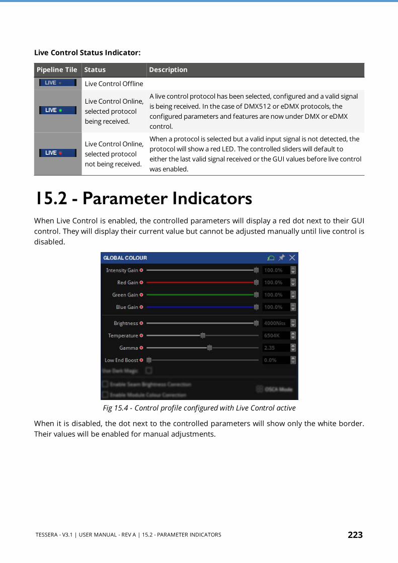
TESSERA - V3.1 | USER MANUAL - REV A | 15.2 - PARAMETER INDICATORS 223
Live Control Status Indicator:
Pipeline Tile Status Description
Live Control Offline
Live Control Online, selected protocol being received.
A live control protocol has been selected, configured and a valid signal is being received. In the case of DMX512 or eDMX protocols, the configured parameters and features are now under DMX or eDMX control.
Live Control Online, selected protocol not being received.
When a protocol is selected but a valid input signal is not detected, the protocol will show a red LED. The controlled sliders will default to either the last valid signal received or the GUI values before live control was enabled.
15.2 - Parameter IndicatorsWhen Live Control is enabled, the controlled parameters will display a red dot next to their GUI control. They will display their current value but cannot be adjusted manually until live control is disabled.
Fig 15.4 - Control profile configured with Live Control active
When it is disabled, the dot next to the controlled parameters will show only the white border. Their values will be enabled for manual adjustments.

224 TESSERA - V3.1 | USER MANUAL - REV A | 15.3 - CONTROL PROFILES
Fig 15.5 - Control profile configured, and Live Control disabled
15.3 - Control ProfilesTessera LED Processors contain a selection of control profiles with various parameters for DMX, Art-Net and sACN modes only. The default profiles cover most use cases, options to modify and create new custom Control Profiles are also available. The default control profiles contained are:
Fig 15.6 - Live Control property editor, displaying Control Profile options

TESSERA - V3.1 | USER MANUAL - REV A | 15.3 - CONTROL PROFILES 225
Control Profile Parameters
170 RGB Groups(510 Channels total if fully assigned)
170x Group assignable sets of Red, Green, Blue
Colour
(28 Channels total if fully assigned)
1x Global control of Red, Green, Blue and Intensity Gain
6x Group assignable sets of Red, Green, Blue and Intensity Gain controls
Colour 127 Groups
(512 Channels total if fully assigned)
1x Global control of Red, Green, Blue and Intensity Gain
127x Group assignable sets of Red, Green, Blue and Intensity Gain controls
Groups(60 Channels total if fully assigned)
6x Assignable sets of group position, orientation and Red, Green, Blue and Intensity Gain controls
Input Controls+
(38 channels total if fully assigned)
1x Global control of Red, Green, Blue and Intensity Gain
3x Assignable controls of Input Colour management parameters
1x Test pattern trigger channel
1x Freeze trigger channel
1x Blackout trigger channel
1x Preset activation channel to trigger up to 127 user-definable presets
Input Controls (30 channels total if fully assigned)
3x Assignable controls of Input Colour management parameters
Preset Activate (1 Channel)
1x Channel to trigger up to 127 user-definable presets
Since some of the sets of parameters that make up these profiles are repeated, and some are common to more than 1 profile it is possible to control all the profiles with 5 suggested DMX libraries. These can be found at C:\Installation path~\Tessera Remote XXX.
15.3.1 - Assign Controls to a Group or InputSome Control Profiles contain multiple sets of group or input controls that allow users to assign each set of controls to a single group (of fixtures) or input (DVI, SDI or HDMI).
This control is in the form of a drop-down menu for each set in the Channel column. When a new profile is selected, all user assignable sets will have the legend “No assigned group” or in the case of input controls “No assigned video input”.
15.3.2 - For Fixture GroupsClicking on this legend will reveal a drop- down menu showing all available fixture groups created within that project file. Please note: if no fixture groups have been created, the menu

226 TESSERA - V3.1 | USER MANUAL - REV A | 15.3 - CONTROL PROFILES
will state None but once fixture groups are created, they will appear in the order of user creation.
NOTE It is important to remember that a group can be composed of a single panel.
Fig 15.7 - Configuring group profile control
Fig 15.8 - Configuring Fixture Groups
In the illustration above, the project includes 4 fixture groups. The user can assign each screen to a set of DMX channels and parameters that are controllable by their DMX, Art Net or sACN control device.
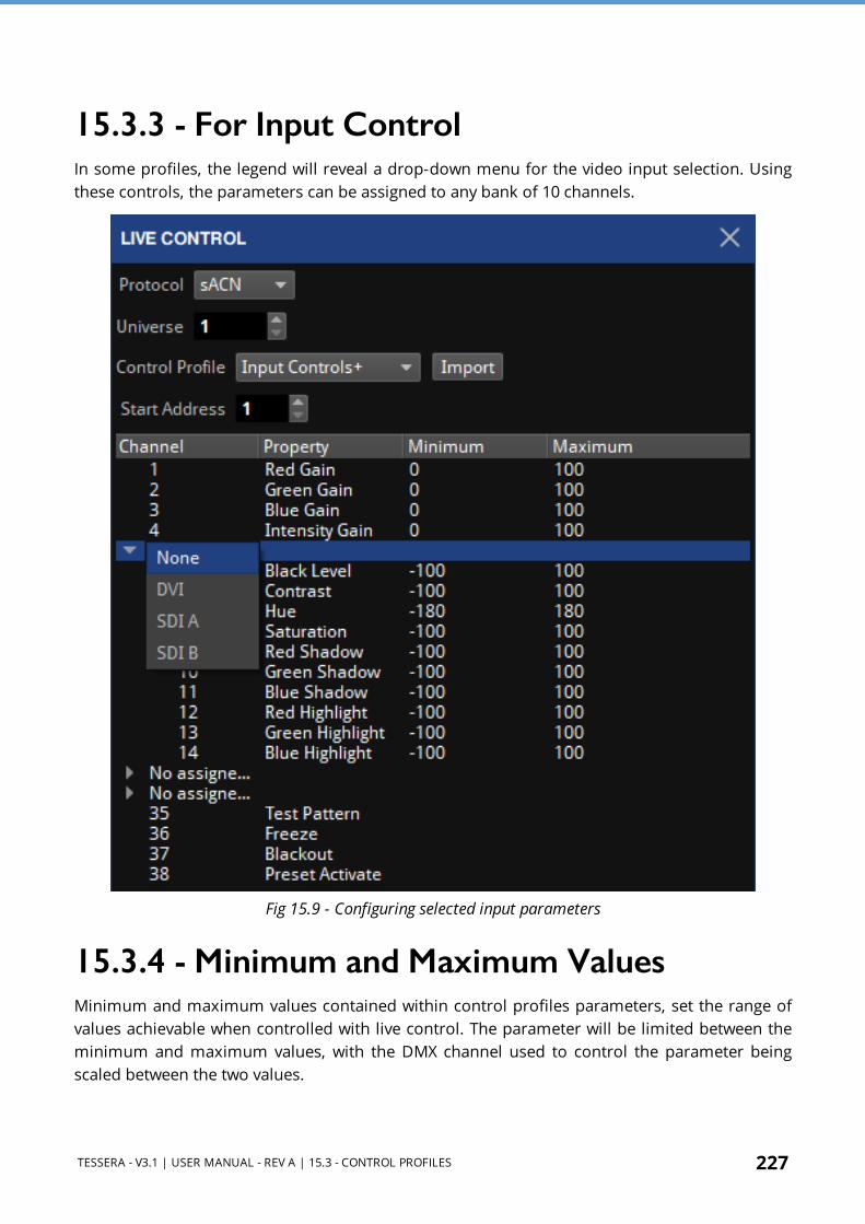
TESSERA - V3.1 | USER MANUAL - REV A | 15.3 - CONTROL PROFILES 227
15.3.3 - For Input ControlIn some profiles, the legend will reveal a drop-down menu for the video input selection. Using these controls, the parameters can be assigned to any bank of 10 channels.
Fig 15.9 - Configuring selected input parameters
15.3.4 - Minimum and Maximum ValuesMinimum and maximum values contained within control profiles parameters, set the range of values achievable when controlled with live control. The parameter will be limited between the minimum and maximum values, with the DMX channel used to control the parameter being scaled between the two values.

228 TESSERA - V3.1 | USER MANUAL - REV A | 15.4 - DMX CONTROL
This is useful in situations where it is important to limit the lowest or highest values of a parameter. An example would be limiting the Intensity gain of a processor to prevent panels being set to a brightness level that is undesirable.
15.3.5 - Default ValuesWhen working with parameters such as group position, once Live control is enabled, the location and orientation of the assigned group on the canvas will become the default location. Minimum and maximum values will be applied from the initial position on the canvas.
If live control is disabled and the assigned group is moved on the canvas, when re-enabling live control the new position of the group will become the default position. The minimum and maximum values will be applied from there.
Stored presets that place the group in one position on the canvas can now move to a different position. For consistent positioning in live control it is best not to move positions of groups once live control programming has begun.
Locking a single parameter on the processor to a value by setting both minimum and maximum values to the same value will prevent live control from changing this channel whilst allowing changes to be made to other parameters within the live control profile.
15.4 - DMX Control
15.4.1 - Configuring the Processor for DMX control
1. Connect a source of DMX512 to the opto-isolated XLR 5 pin input. 2. Go to the Live Control pipeline tile and select DMX from the Control Protocol drop down
menu. 3. Enter a Start Address for the processor. The Start Address will correspond with the DMX
address of the first parameter in the selected Control Profile. 4. Enable Live Control by double-clicking the Live Control pipeline tile or enabling from the
property editor.
If DMX is detected, the Live Control button will light up green to indicate that a source of Live Control has been detected and that Live Control is enabled.

TESSERA - V3.1 | USER MANUAL - REV A | 15.5 - EDMX CONTROL 229
15.5 - EDMX Control
15.5.1 - Configuring the Processor for eDMX controlBoth Art-Net and sACN (Streaming ACN aka E1.31) are supported.
1. Connect an eDMX source to the Net port on the processor’s back panel (either directly or via switch).
2. Go to the Live Control pipeline tile and select Art-Net or sACN from the Control Protocol drop down menu.
3. Ensure that the processor is in an eDMX compliant IP Address and Subnet. This can be changed in the Setting – Processor menu. See Network on page 234 for more information.
4. Enter a Start Address and universe for the processor. The Start Address will correspond with the DMX address of the first parameter in the selected control profile and the universe will determine which eDMX universe the processor will listen to.
5. Enable Live Control by double-clicking the Live Control pipeline tile or enabling from the property editor.
If the eDMX signal is detected, the Live Control pipeline tile will light up green to indicate that a source of live control has been detected and is enabled.
NOTE When connecting multiple processors to a single DMX over Ethernet source it is recommended to manage signal distribution with switches rather than using the second port as a through port to daisy-chained processors.
NOTE When setting up Art-Net, the universe on Tessera LED Processors start from 0 rather than 1.

230 TESSERA - V3.1 | USER MANUAL - REV A | 15.6 - IP CONTROL
15.6 - IP ControlAll processors now support control using standard IP based methods for tighter integration with third party or custom control systems. The following protocols are supported, allowing both status monitoring and remote control of key screen parameters such as brightness or input source:
l HTTP on port 80.
l Telnet on port 23.
Fig 15.10 - IP Control application.
Further information about the IP control is covered in more detail in the IP Control API Documentation, which is published as part of the Tessera Processor Software, available from the Brompton Technology website:
https://www.bromptontech.com/support/#downloads

TESSERA - V3.1 | USER MANUAL - REV A | 15.7 - TESSERA CONTROL 231
15.7 - Tessera Control
Fig 15.11 - Control application GUI
1. Download and install the Tessera Control application on a Windows or Mac computer. 2. Run the application and select the relevant Network Interface from the drop-down. 3. Connect the computer to the Net port on the processor’s back panel (either directly or via
switch). 4. Go to the Live Control property editor and select Tessera Control from the Control
Protocol drop down menu. 5. Choose a channel number and set this in both the Tessera Control application and the
Live Control property editor.The channel number is used to determine which processors are controlled by which instances of the Tessera Control application. By selecting the same channel number on multiple processors, they can be controlled simultaneously from a single instance of the Tessera Control application.

232 TESSERA - V3.1 | USER MANUAL - REV A | 15.7 - TESSERA CONTROL
Fig 15.12 - Selecting the Tessera Control protocol
6. Enable Live Control by double-clicking the Live Control pipeline tile or enabling from the Live Control property editor.
7. If the computer running Tessera Control is detected, the Live Control button will light up green to indicate that a source of Live Control has been detected and that Live Control is enabled.
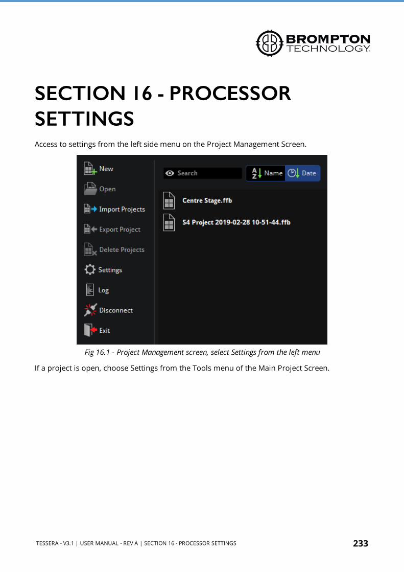
TESSERA - V3.1 | USER MANUAL - REV A | SECTION 16 - PROCESSOR SETTINGS 233
SECTION 16 - PROCESSOR SETTINGSAccess to settings from the left side menu on the Project Management Screen.
Fig 16.1 - Project Management screen, select Settings from the left menu
If a project is open, choose Settings from the Tools menu of the Main Project Screen.
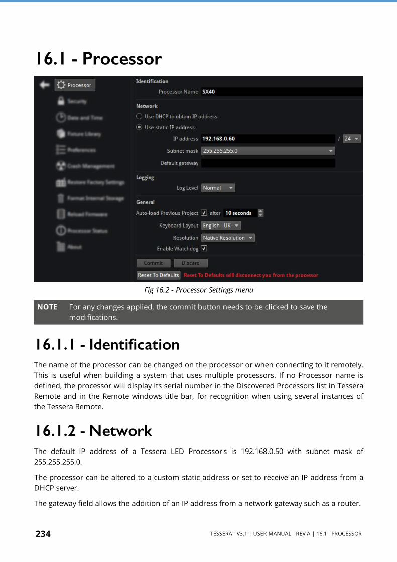
234 TESSERA - V3.1 | USER MANUAL - REV A | 16.1 - PROCESSOR
16.1 - Processor
Fig 16.2 - Processor Settings menu
NOTE For any changes applied, the commit button needs to be clicked to save the modifications.
16.1.1 - IdentificationThe name of the processor can be changed on the processor or when connecting to it remotely. This is useful when building a system that uses multiple processors. If no Processor name is defined, the processor will display its serial number in the Discovered Processors list in Tessera Remote and in the Remote windows title bar, for recognition when using several instances of the Tessera Remote.
16.1.2 - NetworkThe default IP address of a Tessera LED Processor s is 192.168.0.50 with subnet mask of 255.255.255.0.
The processor can be altered to a custom static address or set to receive an IP address from a DHCP server.
The gateway field allows the addition of an IP address from a network gateway such as a router.

TESSERA - V3.1 | USER MANUAL - REV A | 16.2 - GENERAL 235
For a correct communication within a network between processors and/or remote computers, different IP addresses within the same IP range should be defined in each device.
16.2 - General
16.2.1 - Auto Load Previous ProjectWhen the processor is switched on it will display the Start Screen with options to create new or open existing projects. A list of project files will appear in the order of last used and if no file is selected within 10 seconds, the processor will automatically load the previously opened file.
To disable the Auto load feature, untick Auto-load Previous Project. The time for a project to auto-load is also adjusted here.
NOTE It is possible to change the autoload countdown time to a value between 0-3600 seconds. For using this in a live situation, set this value to zero. In the event of a power cut the processor will reboot straight into the current project file with minimal delay.
16.2.2 - Keyboard LayoutDifferent options can be selected to switch between languages that use different keyboard layouts.
Fig 16.3 - Keyboard Layout options
16.2.3 - ResolutionDisplay resolutions for the monitor connected via DisplayPort to display the local UI can be changed. This value is set by default to read the native resolution form the connected monitor.
NOTE This option doesn’t affect the video input or output of the project.

236 TESSERA - V3.1 | USER MANUAL - REV A | 16.2 - GENERAL
16.2.4 - Enable WatchdogThe watchdog is a hardware level process separated from the main processor which monitors and restarts if the processor stops responding, or in the event of a complete processor crash. If watchdog is disabled, the processor will remain in this state until it is manually rebooted. This may be desirable when seeking the cause of the issue. It is recommended to leave this option enabled, by default, watchdog is enabled to ensure processor uptime.
16.2.5 - Limited Settings WindowsWhile in the Local UI and connected to a processor in the remote app, all the settings options are available. There are situations where the settings options may be limited.
16.2.6 - Tessera Remote Offline ModeWhen working in offline mode, there is a reduced number of settings available.
Fig 16.4 - Processor settings while working in offline mode

TESSERA - V3.1 | USER MANUAL - REV A | 16.2 - GENERAL 237
Tessera Remote While Disconnected From ProcessorWhen using Tessera Remote without connecting to a processor
Fig 16.5 - Processor settings when not connected to a processor using Tessera Remote

238 TESSERA - V3.1 | USER MANUAL - REV A | 16.3 - SECURITY
16.3 - SecurityA password can be applied to the processor. Each time a user connects to the processor via Tessera Remote application they will be prompted to enter the password. The password will be reset if factory settings are restored or it can be removed by re-entering the password in this window.
Fig 16.6 - Security settings with no password set- the default setting
Fig 16.7 - Setting a password
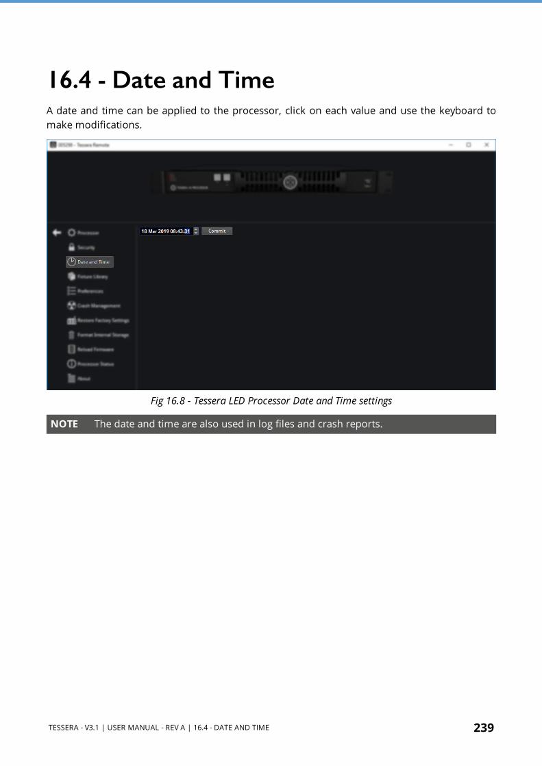
TESSERA - V3.1 | USER MANUAL - REV A | 16.4 - DATE AND TIME 239
16.4 - Date and TimeA date and time can be applied to the processor, click on each value and use the keyboard to make modifications.
Fig 16.8 - Tessera LED Processor Date and Time settings
NOTE The date and time are also used in log files and crash reports.

240 TESSERA - V3.1 | USER MANUAL - REV A | 16.5 - FIXTURE LIBRARY
16.5 - Fixture LibraryTo work with Fixture Packs, it is important to understand the meaning of some concepts:
Term Description
Fixture firmware(Included in a .tfd file) Software needed in the fixtures to be used and communicate with a processor.
Fixture personality(Included in a .tfd file) Software needed in the processor to recognize the fixtures properties.
Tessera Fixture Pack or Fixture Pack
(.tfp) Compilation of fixture firmware. The public releases will include all the updated public fixtures to the date of release.
Fixture library Group of fixtures packs installed in a processor.
All processor firmware releases contain the latest Tessera Fixture Pack at the time of the release. In most cases, using the latest processor firmware release is enough to ensure support for all known panel types.
Check Brompton Technology ’s website for the latest firmware and fixture updates: https://www.bromptontech.com/support
In situations where a new fixture type becomes available or when an urgent fix is required for an existing fixture, Brompton may release a Tessera Fixture Pack (.tfp file) containing the updated list of fixture firmware.
The list of fixture personalities and its firmware version loaded into the processor is detailed in the Fixture Library.
Fig 16.9 - Fixture Library in processor settings

TESSERA - V3.1 | USER MANUAL - REV A | 16.5 - FIXTURE LIBRARY 241
16.5.1 - Pack PriorityTo update Fixture Packs, click Manage Packs. Packs listed here are loaded in descending order with highest priority at the top of the list. The priority can be changed by dragging the desired Fixture Pack above another pack containing the same fixture type.
If a fixture exists in multiple packs, by default the version in the highest priority pack (higher in the list) is used and the same fixture will appear greyed out in lower priority packs.
Fig 16.10 - All fixture firmware contained in a Fixture Pack is shown in Manage Packs
The new priority will take effect immediately for selected panel firmware versions and the project will ask you to update the firmware in the fixtures with the error “XX detected devices are not running the specified firmware version”.
Fig 16.11 - Error message notification shown when detected fixtures are running incorrect firmware versions

242 TESSERA - V3.1 | USER MANUAL - REV A | 16.5 - FIXTURE LIBRARY
Override PriorityThe priority order can be overridden so a selected fixture can use the firmware from a different Fixture Pack than the one with the highest priority.
In the fixture library, select the fixture personality whose priority needs to be modified. At the bottom of the page, the source pack dropdown menu will show all the Fixture Packs installed in the processor.
Fig 16.12 - Overriding priority by selecting source packs to use for a specific fixture
Select the Fixture Pack containing the desired fixture firmware and it will be automatically set as the default pack for that fixture.
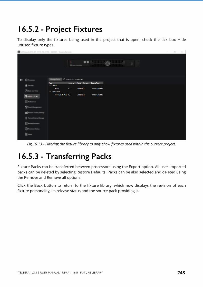
TESSERA - V3.1 | USER MANUAL - REV A | 16.5 - FIXTURE LIBRARY 243
16.5.2 - Project FixturesTo display only the fixtures being used in the project that is open, check the tick box Hide unused fixture types.
Fig 16.13 - Filtering the fixture library to only show fixtures used within the current project.
16.5.3 - Transferring PacksFixture Packs can be transferred between processors using the Export option. All user-imported packs can be deleted by selecting Restore Defaults. Packs can be also selected and deleted using the Remove and Remove all options.
Click the Back button to return to the fixture library, which now displays the revision of each fixture personality, its release status and the source pack providing it.

244 TESSERA - V3.1 | USER MANUAL - REV A | 16.5 - FIXTURE LIBRARY
16.5.4 - Adding and Removing PacksTo import a new Fixture Pack, click Manage Packs and click Add. Select the location where the pack is stored. Select the Fixture Pack and press open to load it into the processor.
Fig 16.14 - Adding a Fixture Pack

TESSERA - V3.1 | USER MANUAL - REV A | 16.6 - PREFERENCES 245
16.6 - Preferences
Fig 16.15 - Preferences menu
16.6.1 - GeneralThe status bar located on the bottom of the Project Canvas. It provides helpful tips and information of where the mouse cursor is located. Unticking the option in the preferences menu hides the bar.
Fig 16.16 - The status bar is located at the bottom of the user interface
16.6.2 - CanvasThis section contains settings to help with selecting and aligning fixtures on the canvas.

246 TESSERA - V3.1 | USER MANUAL - REV A | 16.6 - PREFERENCES
Show Grid Grid dots can be shown or hidden at convenience.
Snap to GridPull fixtures into perfect alignment with the grid. Is enabled by default, helping to align or space fixtures evenly on the canvas.
Snap to FixturesPull fixtures into perfect alignment with other fixtures. Is enabled by default helping to align fixtures evenly on the canvas avoiding overlapping or small gaps.
16.6.3 - Selection ModeSelection modes alter the users mouse cursor for dragging a selection box around fixtures on Canvas View. To change Selection Mode, navigate to Settings > Preferences.
Inside selection area The selection-box must completely enclose fixtures to select them. Overlaps selection area A fixture will be selected if any part of the fixture is within the selection area.
Drag direction mode
Dragging from left to right selects only fixtures that are entirely inside the selection box.
Dragging right to left selects all fixtures that are at least partially inside the selection area.
Fig 16.17 - Selection mode as shown in the Preferences menu
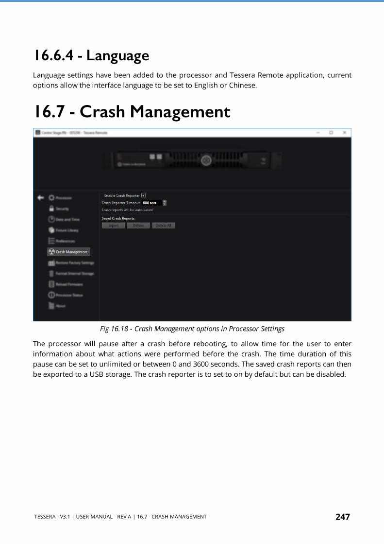
TESSERA - V3.1 | USER MANUAL - REV A | 16.7 - CRASH MANAGEMENT 247
16.6.4 - LanguageLanguage settings have been added to the processor and Tessera Remote application, current options allow the interface language to be set to English or Chinese.
16.7 - Crash Management
Fig 16.18 - Crash Management options in Processor Settings
The processor will pause after a crash before rebooting, to allow time for the user to enter information about what actions were performed before the crash. The time duration of this pause can be set to unlimited or between 0 and 3600 seconds. The saved crash reports can then be exported to a USB storage. The crash reporter is to set to on by default but can be disabled.

248 TESSERA - V3.1 | USER MANUAL - REV A | 16.8 - RESTORE FACTORY SETTINGS
16.8 - Restore Factory Settings
Fig 16.19 - Restore factory settings, with warning prompt before restoring.
Restoring the processor to factory settings will remove all user defined characteristics of the processor and revert all settings back to default. Project files, any imported fixture definition files and fixture firmware not included in the current software release will also be removed. Project files must also be closed before proceeding.
Factory settings can also be restored by pressing and holding the front reset button of the processor for 10 seconds. See Front Panel on page 19 for more information.

TESSERA - V3.1 | USER MANUAL - REV A | 16.9 - FORMAT INTERNAL STORAGE 249
16.9 - Format Internal Storage
Fig 16.20 - Format internal storage menu, displaying warning notification before formatting
Formatting internal storage will clear the memory of the processor. This will delete all project files, any imported fixture definition files and fixture firmware not included in the current software release. The current software version of the processor will be retained after an internal storage format has been performed.

250 TESSERA - V3.1 | USER MANUAL - REV A | 16.10 - RELOAD FIRMWARE
16.10 - Reload Firmware
Fig 16.21 - Processor settings, reload firmware menu
The reload firmware option allows the user to change the software running on the processor. Any firmware builds can be uploaded to the processor and stored in internal flash memory, if the user chooses to do so. The stored file list may contain older or newer builds under the heading Choose from existing.
If a suitable build is unavailable, it can be added from USB storage or from the storage of a computer running Tessera Remote. To do this click Browse and navigate to the location where the firmware is stored.
A dialog box with the heading 'Reload Firmware' is displayed for the user to confirm selection.
Clicking 'Yes' will reload the firmware and save a copy to the local storage. The firmware can now be accessed from the Reload Firmware page.
Reloading firmware with Tessera Remote is similar but the user accesses the file for reloading from the remotely connected computer instead of from USB storage.
The latest and previous processor software releases can be found on our web site: https://www.bromptontech.com/support.
Once the software update is selected, the update process will begin and complete after rebooting and return to the Project management screen upon completion. Existing project files
TESSERA - V3.1 | USER MANUAL - REV A | 16.10 - RELOAD FIRMWARE 251
and additional fixture definition files will remain. It is best practice to export copies of important project files before a firmware upgrade.
NOTE Newer firmware versions are backwards compatible with older versions of firmware. However new projects created on newer versions of firmware will not normally work on older versions.
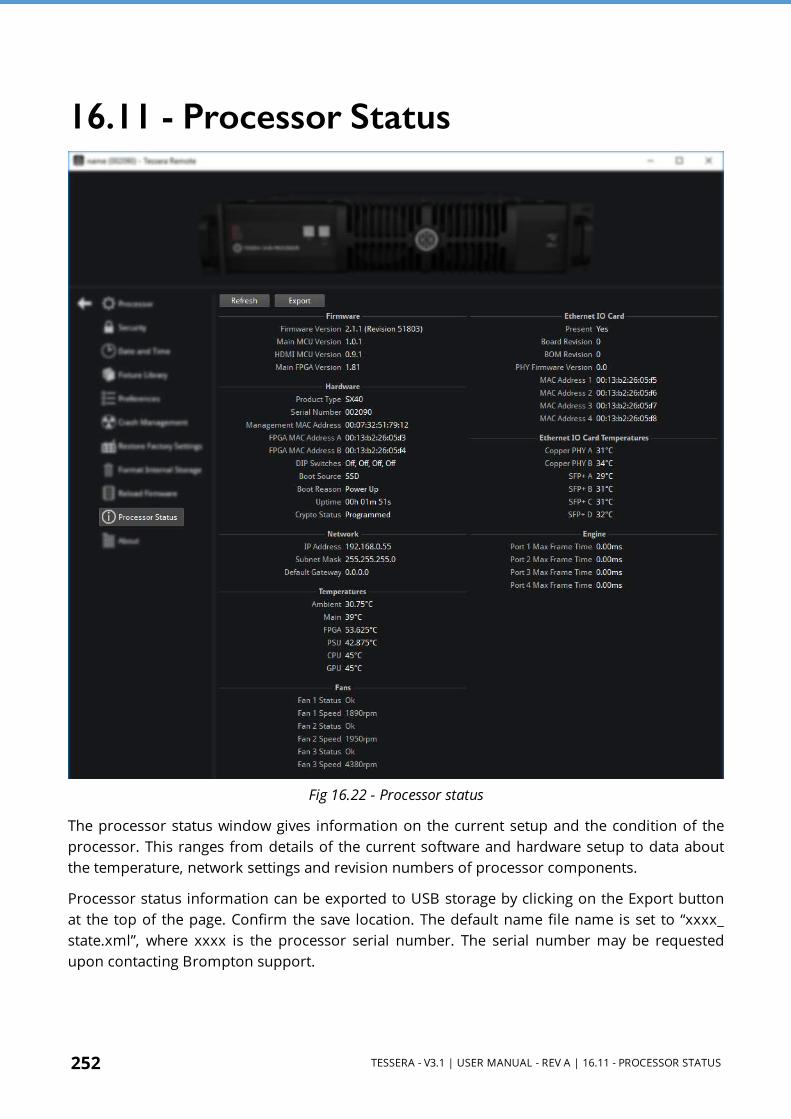
252 TESSERA - V3.1 | USER MANUAL - REV A | 16.11 - PROCESSOR STATUS
16.11 - Processor Status
Fig 16.22 - Processor status
The processor status window gives information on the current setup and the condition of the processor. This ranges from details of the current software and hardware setup to data about the temperature, network settings and revision numbers of processor components.
Processor status information can be exported to USB storage by clicking on the Export button at the top of the page. Confirm the save location. The default name file name is set to “xxxx_state.xml”, where xxxx is the processor serial number. The serial number may be requested upon contacting Brompton support.
TESSERA - V3.1 | USER MANUAL - REV A | 16.12 - ABOUT 253
16.12 - AboutThe About window contains information regarding software or firmware version currently in use, the end user license agreement between Brompton and the user. Third party license agreements relevant to the software and the Brompton contact details including:
l Our company address: International House, 7 High Street, Ealing Broadway, London W5 5DB.
l Support email address: [email protected]
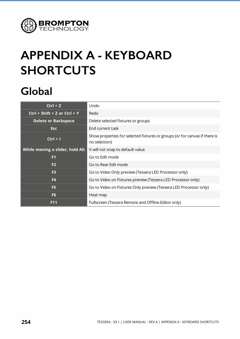
254 TESSERA - V3.1 | USER MANUAL - REV A | APPENDIX A - KEYBOARD SHORTCUTS
APPENDIX A - KEYBOARD SHORTCUTS
GlobalCtrl + Z Undo
Ctrl + Shift + Z or Ctrl + Y Redo
Delete or Backspace Delete selected fixtures or groups
Esc End current task
Ctrl + IShow properties for selected fixtures or groups (or for canvas if there is no selection)
While moving a slider, hold Alt It will not snap to default value
F1 Go to Edit mode
F2 Go to Rear Edit mode
F3 Go to Video Only preview (Tessera LED Processor only)
F4 Go to Video on Fixtures preview (Tessera LED Processor only)
F5 Go to Video on Fixtures Only preview (Tessera LED Processor only)
F6 Heat map
F11 Fullscreen (Tessera Remote and Offline Editor only)

TESSERA - V3.1 | USER MANUAL - REV A | CANVAS 255
CanvasCtrl + G Group
Ctrl + Shift + G Ungroup
Ctrl + left-click on a fixture Toggles its selection
Double left-click on a fixture Select whole string
Shift + left-click on a group Select individual fixture in a group
Ctrl + drag Create duplicates of the selected fixtures or groups
Tab Select next fixture on string
Shift+Tab Select previous fixture on string
Up/Down/Left/Right Arrow Nudge selected fixtures or groups by grid spacing
Shift + Up/Down/Left/Right Arrow Nudge selected fixtures or groups by one pixel
Ctrl+F Fit to screen
Space + Drag Scrolls around canvas
Ctrl + Alt + 0-9 Select OSD page for selected panels
Ctrl + Alt + Up or Down Change OSD font size.
While Adding FixturesShift + left click Add a new fixture and join it to the last added fixture
Left-click and drag Create an array of fixtures
Alt + wheel Set angle of new fixture
While moving fixtures or an array, hold Alt
Invert snapping behaviour
While resizing active area corner, hold Ctrl
Unlock aspect ratio
While resizing active area, hold Alt Invert snapping behaviour
Ctrl + + Zoom In
Ctrl + - Zoom Out
Ctrl + 0 Zoom 1:1
Ctrl + wheel Zoom in and out
Middle-click and drag Zoom to the dragged rectangle
Space + drag Pan the view
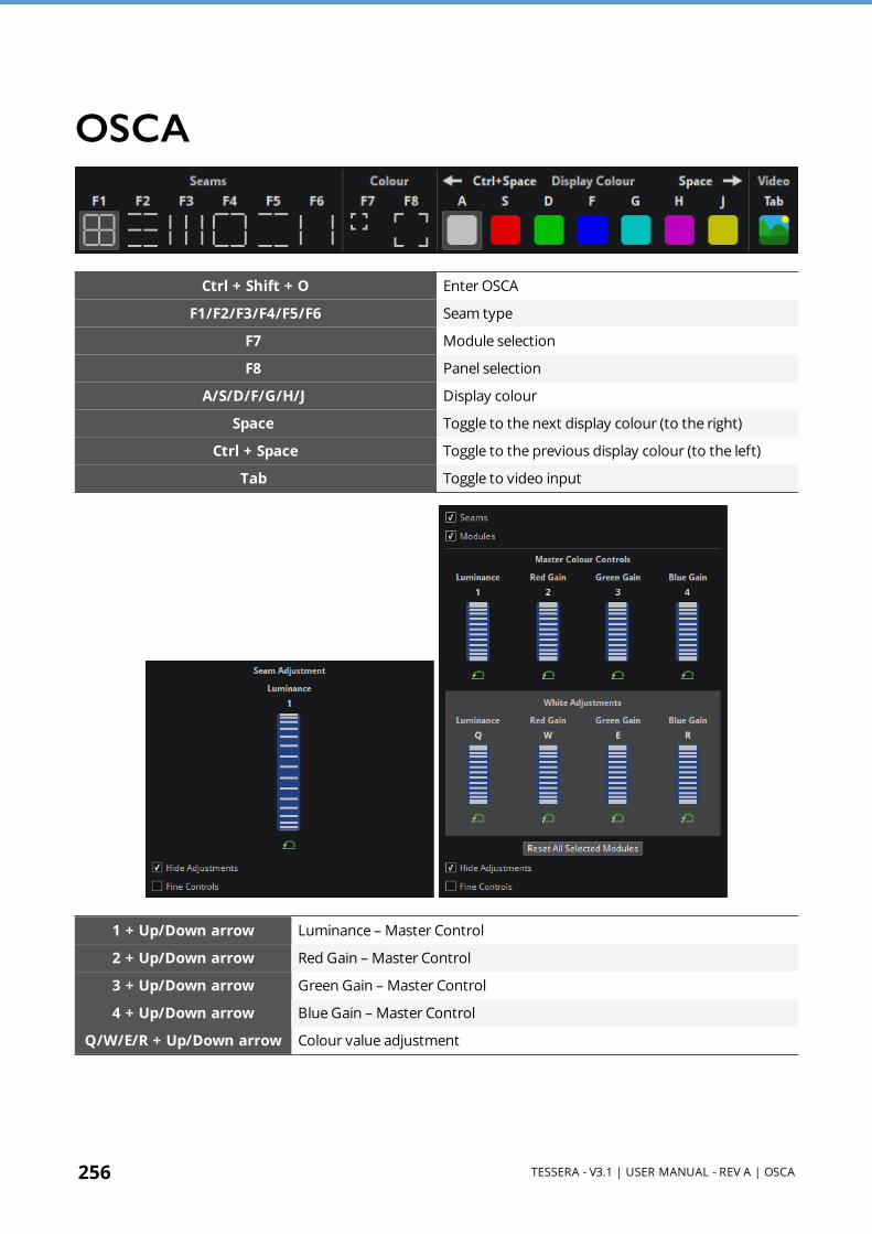
256 TESSERA - V3.1 | USER MANUAL - REV A | OSCA
OSCA
Ctrl + Shift + O Enter OSCA
F1/F2/F3/F4/F5/F6 Seam type
F7 Module selection
F8 Panel selection
A/S/D/F/G/H/J Display colour
Space Toggle to the next display colour (to the right)
Ctrl + Space Toggle to the previous display colour (to the left)
Tab Toggle to video input
1 + Up/Down arrow Luminance – Master Control
2 + Up/Down arrow Red Gain – Master Control
3 + Up/Down arrow Green Gain – Master Control
4 + Up/Down arrow Blue Gain – Master Control
Q/W/E/R + Up/Down arrow Colour value adjustment

TESSERA - V3.1 | USER MANUAL - REV A | APPENDIX B - CABLE REQUIREMENTS FOR TESSERA SX40 AND XD 257
APPENDIX B - CABLE REQUIREMENTS FOR TESSERA SX40 AND XD
Tessera SX40 and XD Cable RequirementsThe Tessera SX40 LED Processor and Tessera XD Distribution Units may be connected by either copper or fibre cables. Each port independently auto- switches between copper and fibre according to the type of cable connected. A mixture of copper and fibre may be used within a single installation (for example, copper for shorter links and fibre for longer ones).
Fibre cables are typically preferable to copper cables, due to their ability to operate over longer distances, their immunity to environmental electrical noise, and their electrical isolation of the connected devices. However, copper cables are typically more widely available, lower cost and easier to terminate, so may be preferred in some situations.
FibreFor fibre connections, Tessera SX40 and XD feature opticalCON DUO connectors. These support single-mode fibre cables terminated with the following connectors:
l Neutrik opticalCON DUO ARMORED (PC) l Neutrik opticalCON DUO X-TREME (PC) l Neutrik opticalCON DUO (PC) l Neutrik opticalCON DUO LITE (PC) l Generic LC Duplex (PC)
Fibre cables must be single-mode fibre, 1310nm, 9/125 μm, with PC or UPC connectors. Multi-mode fibre is not supported, nor are APC connectors. Plugging APC connectors into Tessera SX40 and XD must be avoided as this may cause damage to the connectors.
Tessera SX40 and XD have been tested with fibre cables up to 2KM in length. Longer distances (up to 10KM) may be achievable, but have not been tested by Brompton Technology.
258 TESSERA - V3.1 | USER MANUAL - REV A | 10G ETHERNET COMPATIBILITY
CopperFor copper connections, Tessera SX40 and XD feature Neutrik Cat6A etherCON connectors. These support cables terminated with the following connectors:
l Neutrik etherCON CAT6A l Neutrik etherCON (CAT5e) l Generic Cat6A RJ45 l Generic Cat5e RJ45
Copper cables may consist of:
l Cat6A (typically up to 60 metres) l Cat5e (typically up to 30 metres)
The cable type (Cat5e or Cat6A) must be terminated with the correct connector type, so a Cat6A cable should be terminated with a Cat6A connector whereas Cat5e only needs to be terminated with a Cat5e connector.
Cable lengths have been tested using Belden 1302E CatSnake S/FTP Cat6A and Belden 1305A CatSnake UTP Cat5e, but other types of Cat6A and Cat5e compliant cable may be used. Cable lengths are provided as an indication only for the above Belden cables, as the maximum achievable distance will be dependent on the quality and condition of the cable, the quality of the terminations at both ends, and the electrical environment in which the cable is used. Cat6A should generally be used in preference to Cat5e where possible. Cat7 or higher may also be used, but has not been tested by Brompton Technology.
Shielded cables will typically provide better immunity from external electrical interference. The shield must be electrically connected at both ends of the cable to ensure correct operation. As a side-effect of this, the earths of the devices at each end of the cable will be connected via the cable's shield. Care must therefore be taken to ensure both devices are at the same earth potential when using shielded cables, otherwise data corruption or potentially severe damage to the cable or connected devices may occur.
If earth potentials cannot be guaranteed, we recommend the use of unshielded copper cable (for shorter distances in quiet electrical environments) or fibre (for longer distances or noisy electrical environments), as these both maintain electrical isolation between the connected devices.
10G Ethernet CompatibilityThe use of third-party 10G Ethernet media converters for conversion between copper and fibre formats is discouraged, and should be unnecessary as both Tessera SX40 and XD support both copper and fibre natively. Similarly, the use of third-party 10G Ethernet 'repeaters' (to extend cable lengths) is discouraged. Brompton Technology does not test for correct system operation with the use of third-party media converters or repeaters.

TESSERA - V3.1 | USER MANUAL - REV A | 10G ETHERNET COMPATIBILITY 259
Where it is necessary to convert between fibre and copper, or to 'repeat' a signal for longer transmission distances, a Brompton Technology XD may be used to achieve this. Up to five XDs may be daisy- chained together as required to achieve any necessary signal conversion or repetition.
The use of 10G Ethernet switches is not supported, as these can disrupt the extremely high-bandwidth data flows in unpredictable ways, resulting in intermittent system failures. In addition, 'splitting' 10G Ethernet feeds using switches is not supported. Instead, multiple outputs on the Tessera SX40 should be used, or alternatively up to five XDs may be daisy-chained together as required to achieve outputs to panels at multiple locations.
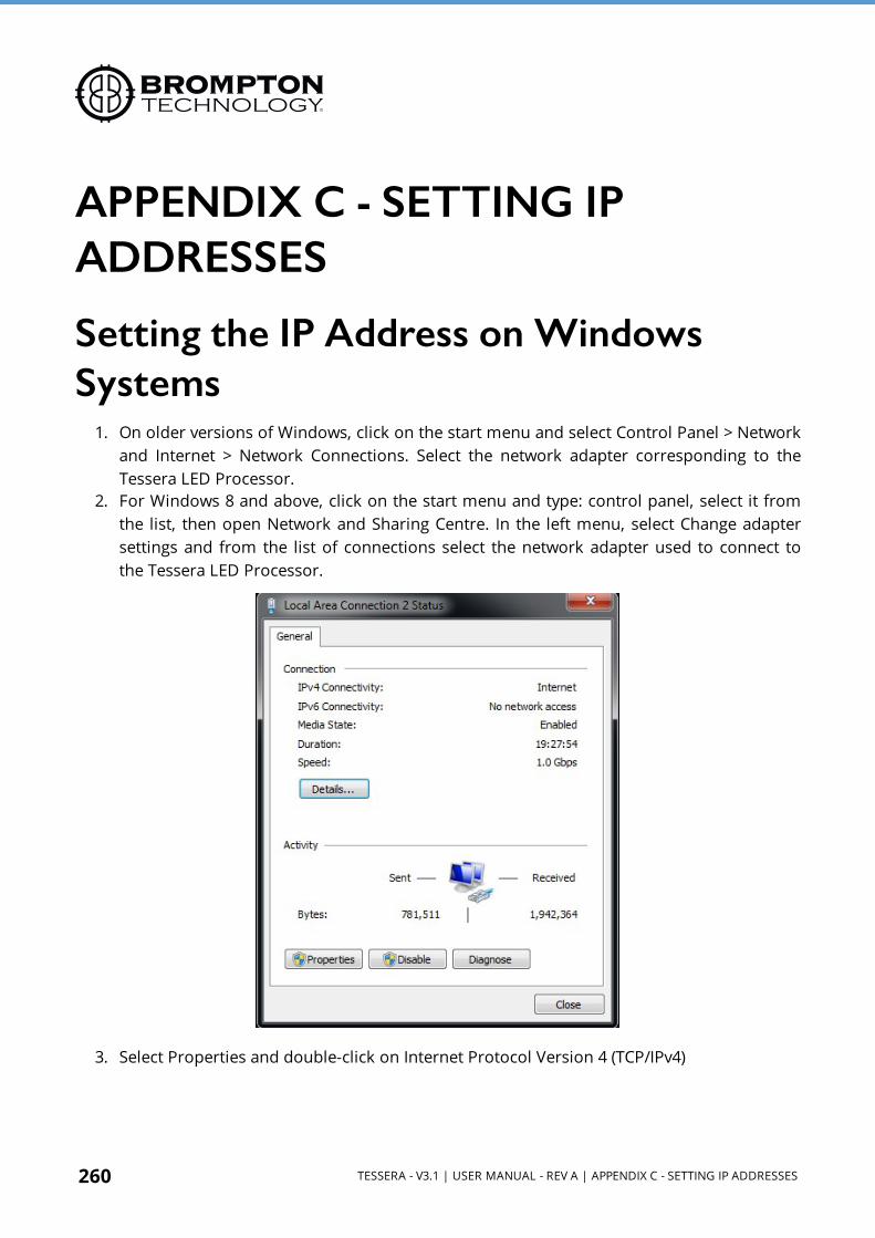
260 TESSERA - V3.1 | USER MANUAL - REV A | APPENDIX C - SETTING IP ADDRESSES
APPENDIX C - SETTING IP ADDRESSES
Setting the IP Address on Windows Systems
1. On older versions of Windows, click on the start menu and select Control Panel > Network and Internet > Network Connections. Select the network adapter corresponding to the Tessera LED Processor.
2. For Windows 8 and above, click on the start menu and type: control panel, select it from the list, then open Network and Sharing Centre. In the left menu, select Change adapter settings and from the list of connections select the network adapter used to connect to the Tessera LED Processor.
3. Select Properties and double-click on Internet Protocol Version 4 (TCP/IPv4)
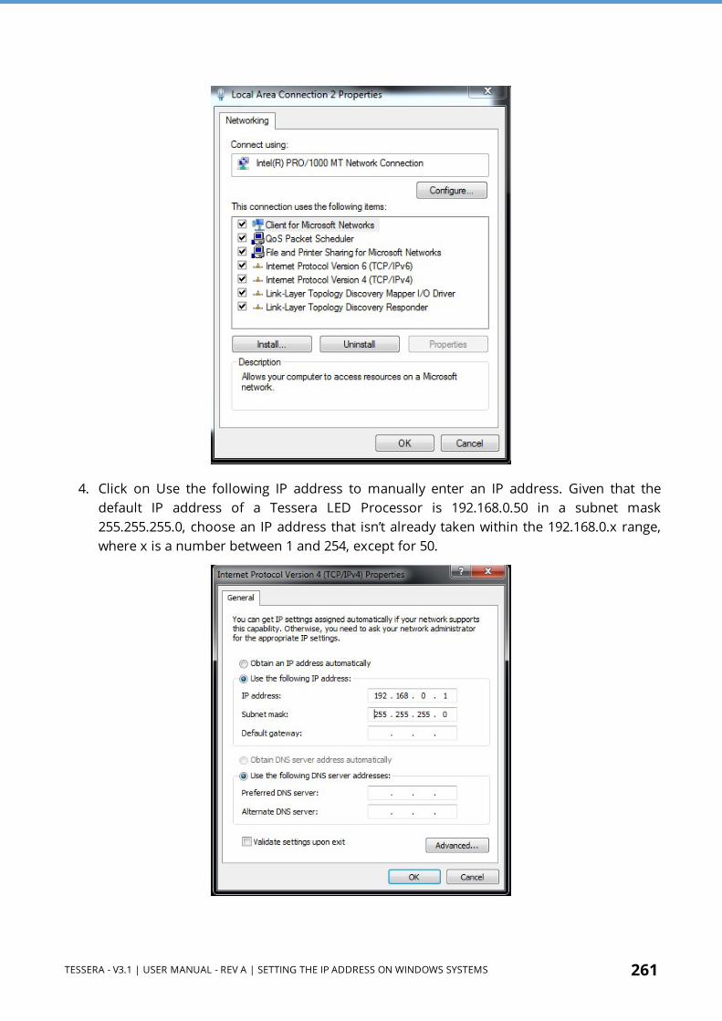
TESSERA - V3.1 | USER MANUAL - REV A | SETTING THE IP ADDRESS ON WINDOWS SYSTEMS 261
4. Click on Use the following IP address to manually enter an IP address. Given that the default IP address of a Tessera LED Processor is 192.168.0.50 in a subnet mask 255.255.255.0, choose an IP address that isn’t already taken within the 192.168.0.x range, where x is a number between 1 and 254, except for 50.

262 TESSERA - V3.1 | USER MANUAL - REV A | SETTING THE IP ADDRESS ON MAC OS X SYSTEMS
5. Click OK to confirm settings and the computer is now be ready to connect to a Tessera LED Processor.
Setting the IP Address on Mac OS X SystemsCurrent Mac computers do not feature a wired Ethernet network interface. To connect to a Tessera LED Processor without using a WLAN requires either a USB, Thunderbolt or USB-C Gigabit Ethernet adapter. All of which are available from Apple or third-party suppliers.
1. Click the Apple symbol in the top left corner of the main screen. Select System Preferences and click on the Network icon.

TESSERA - V3.1 | USER MANUAL - REV A | SETTING THE IP ADDRESS ON MAC OS X SYSTEMS 263
2. Open the Configure IPv4 dropdown menu and select Manual from the list of options.
3. In the IP Address box enter 192.168.0. and a value between 1 and 254 except 50, and a subnet mask of 255.255.255.0. Click Apply and your Mac should be ready to connect to a Tessera LED Processor.

264 TESSERA - V3.1 | USER MANUAL - REV A | APPENDIX D - DMX CHANNEL ALLOCATIONS
APPENDIX D - DMX CHANNEL ALLOCATIONSBelow, is a example list of the Processor Profiles on a Tessera M2 LED Processor with the channel assignments:

TESSERA - V3.1 | USER MANUAL - REV A | APPENDIX D - DMX CHANNEL ALLOCATIONS 265
Colour
Main
Channel Function DMX Default DMX DMX Range (0-255) Actual Range
Red Gain 1 255 0 - 255 0 - 100
Green Gain 2 255 0 - 255 0 - 100
Blue Gain 3 255 0 - 255 0 - 100
Intensity Gain 4 0 0 - 255 0 - 100
Group 1
Channel Function DMX Default DMX DMX Range (0-255) Actual Range
Red Gain 5 255 0 - 255 0 - 100
Green Gain 6 255 0 - 255 0 - 100
Blue Gain 7 255 0 - 255 0 - 100
Intensity Gain 8 0 0 - 255 0 - 100
Group 2
Channel Function DMX Default DMX DMX Range (0-255) Actual Range
Red Gain 9 255 0 - 255 0 - 100
Green Gain 10 255 0 - 255 0 - 100
Blue Gain 11 255 0 - 255 0 - 100
Intensity Gain 12 0 0 - 255 0 - 100
Group 3
Channel Function DMX Default DMX DMX Range (0-255) Actual Range
Red Gain 13 255 0 - 255 0 - 100
Green Gain 14 255 0 - 255 0 - 100
Blue Gain 15 255 0 - 255 0 - 100
Intensity Gain 16 0 0 - 255 0 - 100
Group 4
Channel Function DMX Default DMX DMX Range (0-255) Actual Range
Red Gain 17 255 0 - 255 0 - 100
Green Gain 18 255 0 - 255 0 - 100
Blue Gain 19 255 0 - 255 0 - 100
Intensity Gain 20 0 0 - 255 0 - 100
Group 5
Channel Function DMX Default DMX DMX Range (0-255) Actual Range
Red Gain 21 255 0 - 255 0 - 100
Green Gain 22 255 0 - 255 0 - 100
Blue Gain 23 255 0 - 255 0 - 100

266 TESSERA - V3.1 | USER MANUAL - REV A | APPENDIX D - DMX CHANNEL ALLOCATIONS
Colour
Intensity Gain 24 0 0 - 255 0 - 100
Group 6
Channel Function DMX Default DMX DMX Range (0-255) Actual Range
Red Gain 25 255 0 - 255 0 - 100
Green Gain 26 255 0 - 255 0 - 100
Blue Gain 27 255 0 - 255 0 - 100
Intensity Gain 28 0 0 - 255 0 - 100

TESSERA - V3.1 | USER MANUAL - REV A | APPENDIX D - DMX CHANNEL ALLOCATIONS 267
Groups
Group 1
Channel Function DMX Default DMX DMX Range (0-255) Actual Range
X offset 1-2 32767 0 - 65536 -1920 - 1920
Y offset 3-4 32767 0 - 65536 -1080 - 1080
Rotation Offset 5-6 32767 0 - 65536 -180 - 180
Red Gain 7 255 0 - 255 0 - 100
Green Gain 8 255 0 - 255 0 - 100
Blue Gain 9 255 0 - 255 0 - 100
Intensity Gain 10 0 0 - 255 0 - 100
Group 2
Channel Function DMX Default DMX DMX Range (0-255) Actual Range
X offset 11-12 32767 0 - 65536 -1920 - 1920
Y offset 13-14 32767 0 - 65536 -1080 - 1080
Rotation Offset 15-16 32767 0 - 65536 -180 - 180
Red Gain 17 255 0 - 255 0 - 100
Green Gain 18 255 0 - 255 0 - 100
Blue Gain 19 255 0 - 255 0 - 100
Intensity Gain 20 0 0 - 255 0 - 100
Group 3
Channel Function DMX Default DMX DMX Range (0-255) Actual Range
X offset 21-22 32767 0 - 65536 -1920 - 1920
Y offset 23-24 32767 0 - 65536 -1080 - 1080
Rotation Offset 25-26 32767 0 - 65536 -180 - 180
Red Gain 27 255 0 - 255 0 - 100
Green Gain 28 255 0 - 255 0 - 100
Blue Gain 29 255 0 - 255 0 - 100
Intensity Gain 30 0 0 - 255 0 - 100
Group 4
Channel Function DMX Default DMX DMX Range (0-255) Actual Range
X offset 31-32 32767 0 - 65536 -1920 - 1920
Y offset 33-34 32767 0 - 65536 -1080 - 1080
Rotation Offset 35-36 32767 0 - 65536 -180 - 180
Red Gain 37 255 0 - 255 0 - 100
Green Gain 38 255 0 - 255 0 - 100
Blue Gain 39 255 0 - 255 0 - 100

268 TESSERA - V3.1 | USER MANUAL - REV A | APPENDIX D - DMX CHANNEL ALLOCATIONS
Groups
Intensity Gain 40 0 0 - 255 0 - 100
Group 5
Channel Function DMX Default DMX DMX Range (0-255) Actual Range
X offset 41-42 32767 0 - 65536 -1920 - 1920
Y offset 43-44 32767 0 - 65536 -1080 - 1080
Rotation Offset 45-46 32767 0 - 65536 -180 - 180
Red Gain 47 255 0 - 255 0 - 100
Green Gain 48 255 0 - 255 0 - 100
Blue Gain 49 255 0 - 255 0 - 100
Intensity Gain 50 0 0 - 255 0 - 100
Group 6
Channel Function DMX Default DMX DMX Range (0-255) Actual Range
X offset 51-52 32767 0 - 65536 -1920 - 1920
Y offset 53-54 32767 0 - 65536 -1080 - 1080
Rotation Offset 55-56 32767 0 - 65536 -180 - 180
Red Gain 57 255 0 - 255 0 - 100
Green Gain 58 255 0 - 255 0 - 100
Blue Gain 59 255 0 - 255 0 - 100
Intensity Gain 60 0 0 - 255 0 - 100

TESSERA - V3.1 | USER MANUAL - REV A | APPENDIX D - DMX CHANNEL ALLOCATIONS 269
Input Control
SDI A
Channel Function DMX Default DMX DMX Range (0-255) Actual Range
Black Level 1 127 0 - 255 -100 - 100
Contrast 2 127 0 - 255 -100 - 100
Hue 3 127 0 - 255 -180 - 180
Saturation 4 127 0 - 255 -100 - 100
Red Shadow 5 127 0 - 255 -100 - 100
Green Shadow 6 127 0 - 255 -100 - 100
Blue Shadow 7 127 0 - 255 -100 - 100
Red Highlight 8 127 0 - 255 -100 - 100
Green Highlight 9 127 0 - 255 -100 - 100
Blue Highlight 10 127 0 - 255 -100 - 100
SDI B
Channel Function DMX Default DMX DMX Range (0-255) Actual Range
Black Level 11 127 0 - 255 -100 - 100
Contrast 12 127 0 - 255 -100 - 100
Hue 13 127 0 - 255 -180 - 180
Saturation 14 127 0 - 255 -100 - 100
Red Shadow 15 127 0 - 255 -100 - 100
Green Shadow 16 127 0 - 255 -100 - 100
Blue Shadow 17 127 0 - 255 -100 - 100
Red Highlight 18 127 0 - 255 -100 - 100
Green Highlight 19 127 0 - 255 -100 - 100
Blue Highlight 20 127 0 - 255 -100 - 100
DVI
Channel Function DMX Default DMX DMX Range (0-255) Actual Range
Black Level 21 127 0 - 255 -100 - 100
Contrast 22 127 0 - 255 -100 - 100
Hue 23 127 0 - 255 -180 - 180
Saturation 24 127 0 - 255 -100 - 100
Red Shadow 25 127 0 - 255 -100 - 100
Green Shadow 26 127 0 - 255 -100 - 100
Blue Shadow 27 127 0 - 255 -100 - 100
Red Highlight 28 127 0 - 255 -100 - 100
Green Highlight 29 127 0 - 255 -100 - 100
Blue Highlight 30 127 0 - 255 -100 - 100

270 TESSERA - V3.1 | USER MANUAL - REV A | APPENDIX D - DMX CHANNEL ALLOCATIONS
Input Controls +
Main Colour
Channel Function DMXDefault
DMXDMX Range (0-255) Actual Range
Red Gain 1 255 0 - 255 0 - 100
Green Gain 2 255 0 - 255 0 - 100
Blue Gain 3 255 0 - 255 0 - 100
Intensity Gain 4 0 0 - 255 0 - 100
SDI A
Channel Function DMXDefault
DMXDMX Range (0-255) Actual Range
Hue 5 127 0 - 255 -180 - 180
Saturation 6 127 0 - 255 -100 - 100
Red Shadow 7 127 0 - 255 -100 - 100
Green Shadow 8 127 0 - 255 -100 - 100
Blue Shadow 9 127 0 - 255 -100 - 100
Red Highlight 10 127 0 - 255 -100 - 100
Green Highlight 11 127 0 - 255 -100 - 100
Blue Highlight 12 127 0 - 255 -100 - 100
SDI B
Channel Function DMXDefault
DMXDMX Range (0-255) Actual Range
Hue 13 127 0 - 255 -180 - 180
Saturation 14 127 0 - 255 -100 - 100
Red Shadow 15 127 0 - 255 -100 - 100
Green Shadow 16 127 0 - 255 -100 - 100
Blue Shadow 17 127 0 - 255 -100 - 100
Red Highlight 18 127 0 - 255 -100 - 100
Green Highlight 19 127 0 - 255 -100 - 100
Blue Highlight 20 127 0 - 255 -100 - 100
DVI
Channel Function DMXDefault
DMXDMX Range (0-255) Actual Range
Hue 27 127 0 - 255 -180 - 180
Saturation 28 127 0 - 255 -100 - 100
Red Shadow 29 127 0 - 255 -100 - 100
Green Shadow 30 127 0 - 255 -100 - 100
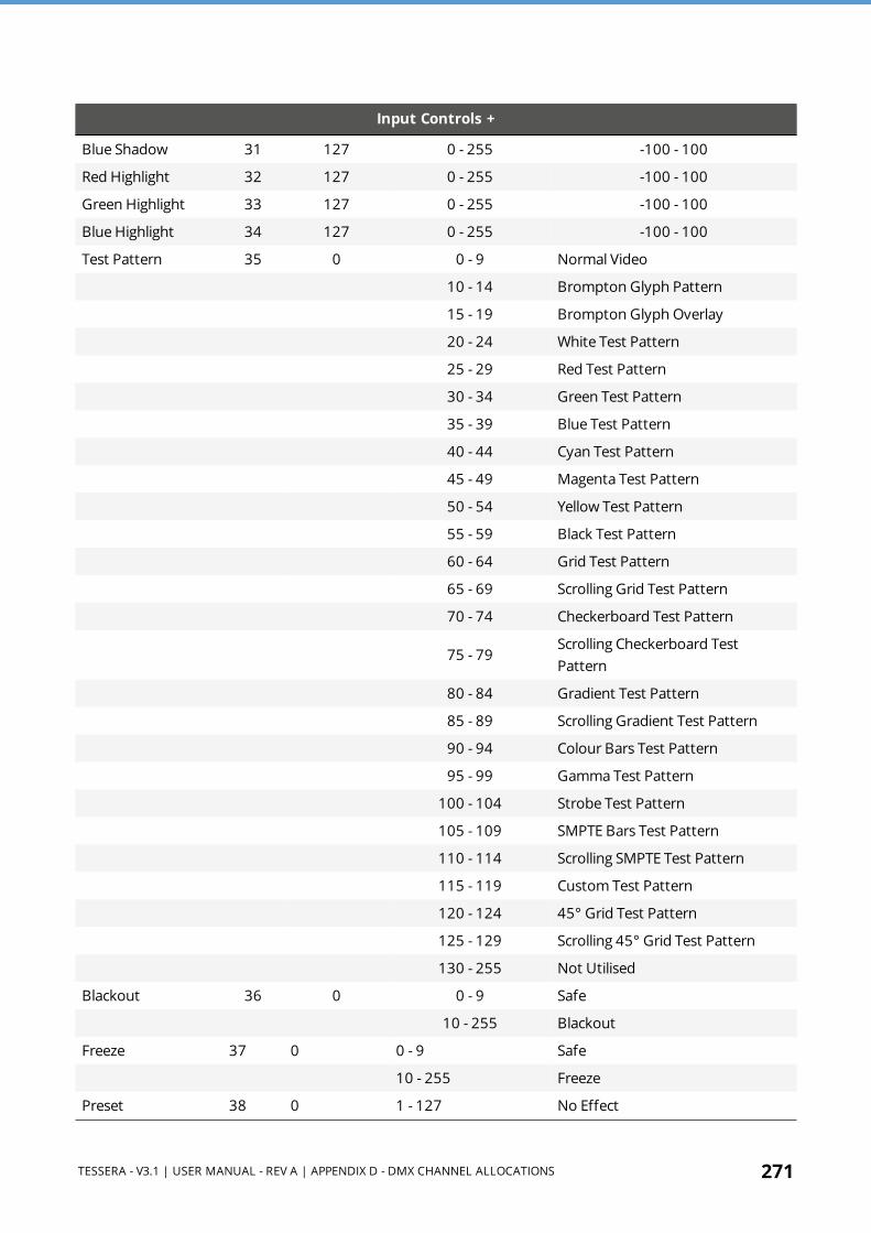
TESSERA - V3.1 | USER MANUAL - REV A | APPENDIX D - DMX CHANNEL ALLOCATIONS 271
Input Controls +
Blue Shadow 31 127 0 - 255 -100 - 100
Red Highlight 32 127 0 - 255 -100 - 100
Green Highlight 33 127 0 - 255 -100 - 100
Blue Highlight 34 127 0 - 255 -100 - 100
Test Pattern 35 0 0 - 9 Normal Video
10 - 14 Brompton Glyph Pattern
15 - 19 Brompton Glyph Overlay
20 - 24 White Test Pattern
25 - 29 Red Test Pattern
30 - 34 Green Test Pattern
35 - 39 Blue Test Pattern
40 - 44 Cyan Test Pattern
45 - 49 Magenta Test Pattern
50 - 54 Yellow Test Pattern
55 - 59 Black Test Pattern
60 - 64 Grid Test Pattern
65 - 69 Scrolling Grid Test Pattern
70 - 74 Checkerboard Test Pattern
75 - 79Scrolling Checkerboard Test Pattern
80 - 84 Gradient Test Pattern
85 - 89 Scrolling Gradient Test Pattern
90 - 94 Colour Bars Test Pattern
95 - 99 Gamma Test Pattern
100 - 104 Strobe Test Pattern
105 - 109 SMPTE Bars Test Pattern
110 - 114 Scrolling SMPTE Test Pattern
115 - 119 Custom Test Pattern
120 - 124 45° Grid Test Pattern
125 - 129 Scrolling 45° Grid Test Pattern
130 - 255 Not Utilised
Blackout 36 0 0 - 9 Safe
10 - 255 Blackout
Freeze 37 0 0 - 9 Safe
10 - 255 Freeze
Preset 38 0 1 - 127 No Effect
272 TESSERA - V3.1 | USER MANUAL - REV A | APPENDIX D - DMX CHANNEL ALLOCATIONS
Input Controls +
128 - 255 Presets 1 - 127

TESSERA - V3.1 | USER MANUAL - REV A | APPENDIX E - WARRANTY 273
APPENDIX E - WARRANTYBrompton Technology Limited (”Brompton”) warrants that its Products will be free from defects in materials and workmanship for a period of two (2) years (”Warranty Period”) from the original date of purchase and that any spare parts will be free from defects in materials and workmanship until the end of the Warranty Period or 3 months from the date of which they have been incorporated into the Product, whichever is the later.
In the event that warranty service is required, please contact Brompton’s support email address: [email protected]
Warranty Conditions 1. Brompton’s obligations are limited to the repair of the defective part or, at its discretion,
replacement of the product or the defective part with a new product or part. 2. The warranty is only valid where Brompton has received payment in full for the product
and the serial number has not been defaced. 3. It is the customer’s obligation to notify Brompton within one week of any suspected defect
and to return the product prepaid to Brompton’s nominated service address. Product will only be received under warranty when they are returned with a recognised RMA number that has been issued by Brompton.
4. Warranty repairs must be carried out by a nominated Brompton employee or Brompton approved agent or service technician. No reimbursement will be made for repairs carried out by non-Brompton personnel or dealers, and any such repair work or damage to the product caused by such repair work will not be covered by this warranty.
5. Product is not considered to be defective in materials or workmanship by reason that it requires adaptation to conform to national or local technical or safety standards in force in any country other than the one for which the product was originally designed or manufactured. This warranty will not cover, and no reimbursement will be made for, such adaptation or any damage which may result. 6. This warranty covers none of the following:
1. Maintenance and repair or replacement of parts due to normal wear and tear. 2. Cost relating to transport, removal or installation of the Product. 3. Misuse, including the failure to use the product for its normal purposes or incorrect
installation. 4. Damage caused by lightning, water, fire, acts of God, war, public disturbances,
incorrect mains voltage, improper ventilation or any other cause beyond the control of Brompton.
5. This warranty is valid for any person who legally acquired possession of the product during the warranty period.

274 TESSERA - V3.1 | USER MANUAL - REV A | WARRANTY CONDITIONS
6. The customer’s statutory rights in any applicable national legislation arising from the purchase are not affected by this warranty. The rights under this warranty are the customer’s sole rights and Brompton shall not be liable for any indirect or consequential loss, damages for any loss of use, time, profits or income, or any damage to related equipment, materials or consumable parts.

TESSERA - V3.1 | USER MANUAL - REV A | GLOSSARY 275
GLOSSARYHere are a list of useful terms used throughout Brompton Technology's products and user interface.
1
1:1 Pixel MappingMapping a tile so that one pixel of content controls one pixel on the tile with no interpolation to compensate for the pitch of that tile
12G-SDISupports bitrates of up to 12 Gbit/s and formats of up to 2160p60
14 Way Colour CorrectorA feature giving the ability to adjust primary, secondary, tertiary, white and black colours, available on Tessera SX40, S8, and M2
3
3G-SDISingle serial link that allows that supports Bitrates up to 2.970 Gbit/s, and 2.970/1.001 Gbit/s and formats up to 1080p60
A
Active AreaArea of canvas that is covered by captured content from viewport, shown by a dashed line border
Add Fixtures From LibraryGives you the ability to add fixtures onto the canvas without having any panels connected to the Processor
Add Fixtures From NetworkAdd fixtures which are connected to the Processor onto the canvas

276 TESSERA - V3.1 | USER MANUAL - REV A | GLOSSARY
Additional Video DelayAdds additional frames of latency to the Processor
Anchor PointThe point around which a group of panels rotates, indicated by a small circle.
ArrayA set of panels built in the canvas view (as distinct from 'group').
Art-NetDistribution protocol allowing DMX512 and RDM data to be transported over ethernet
Aspect RatioAspect ratio refers to the dimensions of the screen or source image. There are standards such as 4:3 or 16:9.
AssociationPlacing panels either online or added from network to your canvas
B
BeaconingA mode in which a fixture on the network displays its Identify test pattern and the status LED on the rear flashes.
BlackoutBlackout for Tessera systems, gives the user control to turn connected fixtures off at any point by either pressing the front panel button or selecting Blackout from the pipeline tiles.
Blind modeMethod of associating fixtures to the canvas without indication from the physical fixtures. Useful for quietly associating without disturbing others.
Brompton TechnologyBrompton Technology is a registered trademark owned by Carallon Ltd
TESSERA - V3.1 | USER MANUAL - REV A | GLOSSARY 277
C
Cable RedundancyWhen fixtures are cabled together in a loop from one port to another on a . Requires enabling when creating a project or from the Network property editor.
Calibration profileCalibration profiles are normally stored on a fixture's LED modules and are created to drive the fixture at its best or for customer needs.
CanvasThe grey rectangle with a solid border in the Main Project Screen.
Canvas BackgroundPlaces an imported image onto the canvas which can be used as a guide when mapping panels
Colour ReplaceA feature to replace and manipulate one specific colour, available on Tessera SX40, S8, and M2
Custom Test PatternA slot for a user to import a JPEG / PNG file as a test pattern.
D
Daisy-ChainOften used with Tessera compatible fixtures, when a fixture is continually connected from one fixture to another.
Dark MagicDark Magic improves the visual quality of the output when operating at low brightnesses.
Delay/LatencyThe time difference added to a video signal by processing. Delay for when it's added intentionally (e.g. on the System tab) and Latency for when it's unintentional (e.g. Low Latency Mode)

278 TESSERA - V3.1 | USER MANUAL - REV A | GLOSSARY
DisplayPortDesigned to replace standards like DVI and VGA. Displayport is required to connect a local monitor to control s.
DMX512Standard for external digital control of fixtures using a control desk.
DP++Dual-Mode DisplayPort is a standard which allows DisplayPort sources to use simple passive adapters to connect HDMI or DVI displays.
DVI-DDVI-D provides a digital only signal
DVI-IDVI-I can support digital and analog signals
F
FailoverWhen a system encounters failure or abnormal termination, failover is switching to a redundant or standby processor.
Fibre opticA fiber optic cable is a network cable that contains strands of glass fibers inside an insulated casing. They're designed for long distance, high-performance data networking and telecommunications.
FirmwareSoftware required for Tessera products to function. Check our website for the latest updates.
Fixture LibraryThe fixture library is a database containing fixture firmware required for the processor to communicate with fixtures.
FixturesBrompton refers to fixtures as the LED panel which connects to our processors or XD units. Fixtures are usually rectangular or square in shape but can also come in all shapes and sizes.

TESSERA - V3.1 | USER MANUAL - REV A | GLOSSARY 279
G
GammaGamma correction is a way to adjust the brightness of mid-tones in the image without affecting the very dark or very bright areas of the image.
Genlock SourceDetermines which input is selected as reference signal the Processor.
Gigabit EthernetGigabit Ethernet (GbE or 1 GigE) is the various technologies for transmitting Ethernet frames at a rate of a gigabit per second (1,000,000,000 bits per second), as defined by the IEEE 802.3-2008 standard.
H
HDMIProprietary audio/video interface for transmitting uncompressed video data and compressed or uncompressed digital audio data from an HDMI-compliant source device.
HDMI 2.0HDMI 2.0 increases the maximum bandwidth to 18.0 Gbit/s 8b/10b encoding for video transmission like previous versions, giving it a maximum video bandwidth of 14.4 Gbit/s. This enables HDMI 2.0 to carry 4K video at 60 Hz with 24 bit/px color depth. HDMI 2.0 include support for the Rec. 2020 color space
Heat MapProjects a heat map across the user interface for all associated panels
HistogramA representation of the colour output of the tiles in a given moment
HueHue is the main indication of colour
L
Live ControlThe Use of DMX, Artnet, sACN or to change values within the Processor

280 TESSERA - V3.1 | USER MANUAL - REV A | GLOSSARY
Low Latency ModeReduces overall latency by one frame, Tessera T1 and M2 processors work at a latency of 3 frames. In low latency mode, the latency is reduced to 2 frames. Tessera S4 is always in low latency mode. Using non-standard canvas sizes automatically witch M2 and T1 processors into low latency mode.
M
Main Project ScreenThis screen refers to the overall view containing configuration options for the canvas, fixtures, topology and many other options.
ModuleAs fixture refers to a whole LED panel, a module is often a removable smaller LED panel with a connector plugged into the fixture.
N
Network bit depthNetwork bit depth refers to the bit depth at which video data is encapsulated, packetized and sent to connected fixtures.
New Project WizardThe popup window for creating a new project that is launched when the 'New...' option is selected
O
OSCAOn-Screen Colour Adjustment is a feature for correcting seams between panels / modules and correcting colour / batch issues per module.
OSDOn- Screen Display, created by Brompton Technology for R2 based fixtures. Displays status information of a fixture on the fixture.

TESSERA - V3.1 | USER MANUAL - REV A | GLOSSARY 281
P
PipelineA section shown above the main project screen, its intention is for the user to configure settings in order of left to right. Each pipeline section is displayed as a pipeline tile.
Pixel pitchPixel pitch refers to the density of pixels. A smaller pixel pitch indicates higher pixel density and higher resolution. Pixel pitch is important because it influences viewing distance.
PresetsUsed to trigger pre defined settings within the Processor, can be triggered manually or via Artnet/DMX
Processor RedundancyWhen 2 processors are cabled together through XD units and outputting identical content to the same fixtures. If one processor crashes or fails, the backup processor will take over outputting. Currently only available with Tessera SX40.
Property EditorA section that appears in Tessera UI when either a pipeline tile or fixtures are selected. Property editors display relevant information and configurable settings.
Protocol Bit DepthThe number of bits per colour sent in video data over the Tessera protocol
R
Rear EditChanges the canvas perspective of the canvas to reflect the layout when standing behind the LED Screen
Root NodesRoot nodes are a control and power box required for connecting and controlling sub-fixtures. Root nodes will house a R2 receiver card.

282 TESSERA - V3.1 | USER MANUAL - REV A | GLOSSARY
S
sA is a collaboration of fixture firmware compiled by Brompton Technology. Made available through www.bromptontech.com New s are often made available along with processor firmware releases.
SaturationSaturation affects depth od colour in an image or video. Reducing saturation will give a mono-chrome image while increasing saturation enhances the colours to give a more vibrant image.
SeamsWith fixtures, when they are built together into a wall, there is often a thin gap between each fixture. Within Tessera manual, this gap is referred to as a seam. Refer to OSCA for more details.
StringAn unbroken sequence of fixtures from a port on a switch or direct from the processor output.
Sub-fixturesSub- fixtures do not have a Tessera interface and so cannot be connected directly to a Processor or XD output. Instead need to be through a single power/control box referred to as a root node.
T
TesseraThe Tessera system comprises processors, distribution units, receiver cards and software. These elements can be used with a wide range of LED fixtures.
Tessera M2The most popular processor to drive HD content. It can control a nominal 2 million pixels over four 1 Gigabit outputs to a fixture count of up to 2000. Supports 3G-SDI and DVI-I inputs.
Tessera Offline EditorTessera offline editor, used for planning, mapping fixtures and topology before connecting to a processor or before fixtures are connected.

TESSERA - V3.1 | USER MANUAL - REV A | GLOSSARY 283
Tessera S4Ideal for high resolution screens. The S4 processor does not have the front-side processing, scaling or degree by degree rotation of the T1 and the M2 but can control the same number of pixels across four Gigabit outputs as the M2
Tessera S8A mid-range processor perfect for high-profile projects that don’t require large output capacity but want the full suite of Tessera processing features.
Tessera SX40Currently our highest capacity processor, able to support a nominal 9 million pixels and 4k canvas resolutions with HDMI 2.0 and 12G SDI inputs. Four 10 Gigabit ports allow data transfer using fibre or CAT6 copper cable. The SX40 can support up to 2000 connected fixtures and offers maximum flexibility with the use of the XD distribution system
Tessera T1Ideal for creative shows requiring flexibility over number of fixtures. It has a DVI-D input and supports a capacity of 0.5 million pixels in a HD canvas. The T1 includes most of the main features available with the Tessera systems, with one output port supporting up to 500 fixtures.
TopologyWith Tessera systems, the topology refers to how fixtures are cabled to the processor, the route of where each panel is connected and to which port of the processor.
TransceiverA transceiver is a device comprising both a transmitter and a receiver that are combined and share common circuitry or a single housing
V
ViewportRegion of incoming video feed captured to canvas.

Established in 2012, Brompton Technology is part of the Carallon group of companies based in West London. It operates in the rapidly expanding LED Video display sector, and product designs come from years of industry and engineering experience, and an acute understanding of the current marketplace. This has resulted in it fast becoming a globally known and respected brand within this sector. More information can be found at www.bromptontech.com.
© 2021 Brompton Technology Ltd., International House, 7 High Street, Ealing Broadway, London W5 5DB | www.bromptontech.com