user manual popa light pole pl dg 2 - popa tower … b.v. user manual popa light pole pl dg 2 rev....
TRANSCRIPT

Popa B.V.
User manual Popa light pole PL DG 2 rev. 00 1 / 28
User manual
Popa light pole PL DG 2
Popa B.V.
P.O. Box 117
5066 ZJ Moergestel (Holland)
Tel: 0031 (0) 135134032
Mobile: 0031 (0) 6 20398762
e-mail: [email protected]

Popa B.V.
User manual Popa light pole PL DG 2 rev. 00 2 / 28

Popa B.V.
User manual Popa light pole PL DG 2 rev. 00 3 / 28
0. Content
0. Content ........................................................ Fout! Bladw ijzer niet gedef inieerd.
1. Foreword ................................................................................................. 4
2. Introduction ............................................................................................. 5
3. Technical Specifications ....................................................................... 5
4. Safety ......................................................... Fout! Bladw ijzer niet gedef inieerd.
4.1 SAFETY DEVICES: ..................................................................................... 6 4.2 SAFETY REGULATIONS .............................................................................. 6 4.3 RESIDUAL RISK ......................................................................................... 7
5. Description of the Popa light pole ...................................................... 8
5.1 GENERATOR ............................................. FOUT! BLADWIJZER NIET GEDEFINIEERD. 5.2 START / STOP PDM1 MODULE ....................................................................... 12 5.3 SAFETY REAY IB-PROTECTOR ...................................................................... 13
6. Installation ................................................. Fout! Bladw ijzer niet gedef inieerd.
7. Operation ................................................... Fout! Bladw ijzer niet gedef inieerd.
7.1 TIMER CLOCK. .......................................................................................... 18 7.2 LIGHT SENSOR. ......................................................................................... 18
8. Maintenance .............................................. Fout! Bladw ijzer niet gedef inieerd.
9. Malfunction, Repair ............................................................................. 20
9.1 FAULT FUNCTIONS SAFETY RELATIONS IB-PROTECTOR ................................ 20 9.2 FAULT FUNCTIONS OF THE PDM1 MODULE ................................................. 23
10. Disassembly, removal ....................................................................... 25
11. Schedules, drawings, pictures ........................................................ 26
11.1 CONNECTION PDM1................................ FOUT! BLADWIJZER NIET GEDEFINIEERD.
12. Conformity statements .................................................................... 27
13. Attachments ........................................... Fout! Bladw ijzer niet gedef inieerd.
© copyright : Popa B.V. March 2016
Nothing in this documentat ion is allow ed to be re-produced in any w ay w ith the permission of Popa B.V. Apart f rom the
parts that are meant to be re-produced for the use of this documentat ion such as the brief instruct ions.

Popa B.V.
User manual Popa light pole PL DG 2 rev. 00 4 / 28
1. Foreword
The Popa light pole PL DG 2 is developed and produced according the latest state of the
technology. This means that the machine w ill comply w ith the applicable European
guidelines regarding health and safety. The Popa light pole PL DG 2 is provided w ith CE-
classif icat ion.
The letter or manufacturer is not liable for unsafe situat ions, accidents and damages,
that are caused by:
Ignoring the w arnings or regulat ions as stated on the installat ion, the machine or in
the user manual
Insuff icient maintenance
Use for other applicat ions then stated in the user manual
Adjustments to the Popa light pole PL DG 2 by third part ies. This also includes the
applicat ion of other replacement parts then the ones prescribed and changing of the
operat ing system.
Manuals of the follow ing main components w ill be included:
- Diesel engine from Kubota: D1105-E.
- Sincro SK160SA1
- IB Protector:
A brief instruct ion card is present at the inside of the cabinet .
This user manual contains appropriate user instruct ions for use, maintenance and repair.
These instruct ions should be respected and follow ed.
(Furthermore, the General delivery and payment terms of the Events Union are
applicable)
The nameplate is attached to the lef t side of the inner side of the cabinet above the tank
on the panel of the sw itch cabinets.

Popa B.V.
User manual Popa light pole PL DG 2 rev. 00 5 / 28
2. Introduction
The Popa light pole PL DG 2 is developed and produced to supply light to temporary
carparks, building sites, emergencies and night w ork during events. The Popa light pole
PL DG 2 operates as stand-alone.
Connect ion to the pow er supply to supply pow er back is not allow ed
The Popa light pole PL DG 2 consists of a casing, that is equipped w ith a generator,
pow ered by a diesel engine, to generate pow er to put t he light f ixtures in operat ion, a
diesel tank, equipped w ith a drip tray, a retractable and extending light pole, a hydraulic
unit for retract ing and extending the light pole and an operat ing system for the
generator. Furthermore, the Popa PL DG 2 light pole is equipped w ith several service
sockets.
The Popa light pole has the follow ing main components,
- Diesel engine from Kubota: D1105-E.
- Sincro SK160SA1
- IB Protector
- Hydraulic generator (compact generator): 1,6 cc pump; 2,25 l / min.
- Light pole w ith 4 x 1000 Watt lamps
3. Technical Specifications
Measurements (lxw xh) : 1200 x 1200 x 2700 mm
Maximum height : 8,5 m.
Max. inclinat ion at installat ion : 5º
Lights : 4 x 1000 Watt, NAV-T light or HQI
Weight : + /- 1400 kg.
Diesel generator : Manufacturer Kubota and Sincro
Tank capacity : approx. 280 l
Usage : Depending on the load (1,5-2) l/hour
Operat ing hours : + /- 10 days
Capacity : 230 V, 8 KVA, fused w ith 16A.
Service out lets : phase, 0, earthed, plug and sockets for 32, 16, 10 A
Operat ing cabinet : IP20
Start ing battery : 12 Volt direct current
Hydraulic generator : 230 V, 0,75 kW: EN Motoren B.V.; type BOB-04
Maximum w ind speed : 6 (w ithout support legs)
Noise level : Lw A 95 (w ith an opened door)
See also the provided manuals.

Popa B.V.
User manual Popa light pole PL DG 2 rev. 00 6 / 28
4. Safety
All manuals of the main components are provided. In addit ion, they w ill also include
(safety) instruct ions.
4.1 Safety devices:
The follow ing safety devices are present on the Popa PL DG 2 light pole:
Temperature protect ion, overload protect ion, protect ion oil level of the generator
Lockable casing
Diesel tank w ith drip tray
Over voltage protect ion
Insulat ion guard (Safety relay IB-protector; see chapter 6.x for a descript ion)
Emergency stop sw itch
Hydraulic system w ith single-operat ing cylinder, equipped w ith release valve and
hose rupture protect ion
Release valve to retract the light pole in case of emergencies (shutdow n of the
diesel engine)
4.2 Safety regulations
The follow ing regulat ions are important for safe usage of the Popa light pole:
Public / bystanders are not allowed access to the cabinet. The key to open the
casing should always be kept by the hirer.
The Popa light pole PL DG 2 should alw ays be placed on a f lat and stabile surface.
When the w ind speed is more than 6, the Popa light pole PL DG 2 should be
retracted in accordance w ith the w ind speed/height diagram.
Do not connect the light pole to the public pow er supply or any other energy
source.
The access door should remain closed for bystanders / public.
After serious rain show ers the drip tray should be empties.
When refuelling/ref illing the generator should alw ays be stopped.
With maintenance and repair, the battery should alw ays be disconnected and the
sw itch should be in ‘‘0 ’’ posit ion.
Start ing w ith start ing cables is the same as w ith cars.
Never w ork on the generator or the PDM1 if the generator is running.
Have maintenance done by trained staff
Do not w ear loose clothes near the pow er generator.
Never let the generator run if the protect ion plates of the generator, the engine or
the alternator have been dismantled.
Never let the generator run in badly vent ilated rooms; overheat ing and serious
damage could occur.
See also the provided manuals.
Popa B.V.
User manual Popa light pole PL DG 2 rev. 00 7 / 28
4.3 Residual risk
The manufacturer searched for an opt imum betw een funct ionality of the light pole, the
safety and the w orkability. All moving parts are shielded. Vandalism, improper use and
natural disasters excluded, the Popa light pole has the follow ing risks:
The key to open the casing should always be kept by the hirer to ensure that the public / bystanders have no access to the cabinet.
With a w ind speed > 6 the pole should be retracted to a lesser height.
The manufacturer considers these risks as residual risks.
Popa B.V.
User manual Popa light pole PL DG 2 rev. 00 8 / 28
5. Description of the Popa light pole
The Popa light pole consists of the follow ing parts:
Casing
The casing consists of a metal f rame, integrated w ith a drip tray and equipped w ith
plast ic (Trespa) side w alls. The access door is equipped w ith a lock. Furthermore, the
casing is equipped w ith vent ilat ion facilit ies for the air circulat ion. Plus 4 spoon holes
have been applied so it can be moved a forklif t t ruck.
Generator
The generator is pow ered by a diesel engine and provides the light f ixtures w ith energy.
Through the operat ing system for the generator, the user can operate the generator. The
operat ing system is equipped w ith signals for overloading, temperature, protec t ion oil
level and a voltage meter to read the pow er.
Light fixtures
The light pole is equipped w ith 4 light f ixtures (gas discharge lamps), that have been
f it ted in such a manner that they can be stored in a compact w ay w ithin the frame w hen
retract ing or extending the light f ixtures.
Diesel tank
The diesel tank of 280 lit res is equipped w ith 2 inlet and out let valves for service and
repair purposes. Furthermore, the tank is placed above the drip tray.
Hydraulic unit
The hydraulic unit takes care of the retract ing and extending of the light pole. The
hydraulic pump is pow ered by an electric engine. The pow er supply is provided by the
generator. For retract ing and extending a single-operat ing cylinder is used, so gradual
movements are possible.
The hydraulic unit is equipped w ith a 12V magnet release valve to low er the light pole in
case of emergencies and therefore st ill can be transported.
Retracting and extending light pole
The light pole consists of 6 telescoping segments, that are attached to the frame and
that can be extended w ith the use of 1 single-operat ing hydraulic cylinder and 4 steel
cables. The light f ixtures are attached (reversed) to a H-frame that is f it ted to the top
segment, therefore they are easy to point.
Operating system
The operat ing system is attached to the inner side of the cabinet. The hirer should
alw ays keep the key to this. From the operat ing system the generator can be started
and the lights can be sw itched on and off .

Popa B.V.
User manual Popa light pole PL DG 2 rev. 00 9 / 28
Options
The standard operat ing system of the generator can be extended w ith the follow ing
opt ions:
- Service sockets for extra facilit ies and the use of electronic hand tools.
- Timer clock. With the t imer clock the Popa light pole can be automatically started
and stopped at programmed t imings.
- Light sensor. With the light sensor the start ing and stopping is regulated by the
light intensity of the surroundings.
- Track and Trace GPS Buddy. With this opt ion the light pole can be started and
stopped remotely and the status of the light pole can be read. In case of theft the
Popa light pole can be traced.
5.1 Generator
First read the provided engine and alternator manual of the generator. This w ill explain
the operat ion, the maintenance and the dangers of incorrect use.
All information in this manual is based on the standard versions of the EP8DE, EP9TDE
and EP183TDE types. Generators equipped w ith opt ions can contain slight ly deviat ing
information. Contact your EUROPOWER dealer for extra information about this.
Short description
Type: EP8DE
Capacity: 1 x 230V: 8kVA
Alternator: Leroy Somer LSA37L5 w ith capacitor (brushless)
Engine: KUBOTA D1105, 3 cylinder, 1123cm³, 1500 tpm, w ater cooled
Tank capacity: 55 lit re
Measurements: 130 x 64 x 86 cm
Weight: 305 kg
Noise level: Lw A 95 dB(A)
The main components of the pow er generator are: the w ater cooled KUBOTA diesel
engine (1500tpm for EP8DE and EP9TDE, 3000tpm for EP183TDE), the alternator, the
control panel and the chassis.
For engine and alternator specif icat ions w e like to refer you t o the engine and alternator
manual provided w ith every generator.
The chassis of the alternator serves as fuel tank and contains the fuel f iller, the
mechanical fuel level meter, the fuel discharge cap (for cleaning the fuel tank), 4 f it t ing
holes (for f ixed installat ion of the generator), the battery support and the f ixing support
for the (manual) oil discharge pump.

Popa B.V.
User manual Popa light pole PL DG 2 rev. 00 10 / 28
Control panel (see picture)
On the control panel you w ill f ind:
- Ignit ion (off / on / start ing / glow ing)
- Control lamp green (ignit ion on / of f ), lamp w ill light up w hen ignit ion is on
- Control lamp red (charging current battery), lamp w ill light up w hen battery
w ill not charged
- Hour counter
- Voltage meter
- Sockets:
o EP8DE: 2 x schuko 230V + 1 x 3p CEE 32A
In the control panel you w ill f ind:
- 2 relays 12V/25A for oil pressure and cool w ater temperature protect ion w ith
the use of a stop magnet (engine w ill shut dow n w hen the oil level is too low
or the cool w ater temperature is too high)
- Thermal magnetic protect ion
- Leakage circuit breaker (earthed pin supplied)
Use of the generator

Popa B.V.
User manual Popa light pole PL DG 2 rev. 00 11 / 28
PLEASE NOTE! The generators EP8DE/9TDE/183TDE are equipped w ith a 12V
electronic fuel pump. This pump cannot ‘‘ run dry ’’ . If the engine shuts dow n due to lack
of fuel, turn ignit ion key to ‘‘OFF’’ as soon as possible.
To start engine:
- check the oil level
- check the fuel level
- ignite for about 10 seconds
- start the engine w ith the ignit ion key
- let the generator w arm up for a few minutes before using it .
Loading the generator:
- on the nameplate of the generator you w ill f ind the capacity details / allow able load
voltage of the generator.
- When overloading the thermal magnetic protect ion, f it t ed in the control panel, w ill
sw itch off af ter a short w hile. Check and low er the load and then sw itch the
protect ion back on.
- In case of a short circuit the thermal magnetic protect ion w ill sw itch off
immediately! Check the cause of the short circuit and then sw itch the protect ion
back on.
- Never let the diesel engine run, unloaded or loaded, for a long period of t ime (=
more than 30 minutes). This can cause serious damage to the engine.
Turn off the generator
Leave the generator to run for a few minutes unloaded before turning it of f . This w ill
‘‘cool dow n’’ the generator. Turn the generator off w ith the ignit ion key.
Cooling
- Ensure that the intake of cooling air by the engine and alternator is not obstructed.
- Ensure for a free out let of the w arm engine and alternator cooling air, as w ell as
exhaust fumes.
- Never let the generator run in a closed area!
Protections
- engine: oil level protect ion and cool w ater temperature protect ion.
- alternator: thermal magnetic protect ion
Safety for the users
The standard versions of these pow er generator are supplied w ith leakage circuit breaker
and thermal magnetic protect ion, according the connect ion of the IN-S netw ork system.
To connect class 1 equipment (earthed equipment) and class 2 equipment (double
insulated equipment, to be recognised by the sign ‘‘double square’’ on the equipment,
there are no restrict ions for the number of equipment that can be connected at the same
t ime.
Respect the legally used minimum diameter (mm²) and maximum length of the extension
leads (sw itching of the thermal magnetic protect ion in case of a short circuit).

Popa B.V.
User manual Popa light pole PL DG 2 rev. 00 12 / 28
5.2 Start / stop PDM1 Module
The PDM1 module is an automatic start and engine protection module to start the engine “manually” or “remote”. The PDM will shut down the engine if there is a fault in the oil pressure/level or engine temperature. Carefully read this manual before working with the PDM1 module and the power generator. By following this manual your generator with PDM1 module will provide a trouble-free operation for many years.
Technical information
Power supply PDM1:
- Input voltage
- Voltage range
- Minimum input voltage w hen start ing
- Shut dow n PDM1
- Maximum pow er use
- Immunity against micro interrupt ion
- 12VDC or 24VDC
- 9VDC to 33VDC
- 6,7VDC
- 4VDC (150ms)
- 60mA w ith 12VDC or 24VDC
- 200ms
Digital inputs:
Oil --- temperature --- fuel
- Input
- Input voltage
- Input MINIMUM voltage
- Input MAXIMUM voltage
- Input delay
- Negative
- = < 4mA (12VDC)
= < 8mA (24VDC)
- = < 1,5V
- = > 5,3V
- 1s
Digital input for starting remotely:
- Input
- Input voltage
- Input MINIMUM voltage
- Input MAXIMUM voltage
- Input delay
- Posit ive
- = < 4mA (12VDC)
= < 8mA (24VDC)
- = < 1,5V
- = > 5,3V
- 1s
Programmable relay output:
- Type contact
- Maximum voltage
- Maximum voltage at 30VDC
- 1 NO contact
- 30VDC
- 5A
Operation limit:
- Operat ion temperature
- Storing temperature
- -20° C to + 60° C
- -30° C to + 80° C
Connection socket:
- Type of plugs
- Thickness w ire
- Maximum turn on moment
- Plug connectors
- 0,2mm² to 2,5mm²
- 0,8Nm
Casing:
- Type:
- In-built

Popa B.V.
User manual Popa light pole PL DG 2 rev. 00 13 / 28
- Measurement front side casing
- Measurement installat ion size
- Material
- Protect ion grade
- Weight
- 96x48x100 mm
- 91x44 mm
- Self-ext inguishing UL94 black
- IP41 (front)
- 160g
Use of the PDM1
Manual operation
- PDM1 is ignited w ith the sw itch button ‘‘0/1 ’’ .
o LED 1-2-E-D-C-B-A w ill burn once.
o LED 1-2-E-D-C-B-A w ill burn after each other.
o The 7 LEDs w ill go off at the same t ime
o Engine w ill ignite.
o LED 1 and LED 2 w ill burn immediately during ignit ion.
- When the engine is running the PDM1 w ill f lash the LED ‘‘alarms on’’ (LED 2) after
8 seconds; this means that the alarms are sw itched on.
- To turn of the generator, the sw itch button ‘‘0/1 ’’ should be sw itched off again.
The PDM1 w ill be w ithout pow er!
Automatic operation:
- Connect the make contact (NO) in accordance w ith the attached schedule.
o The ignit ion cycle is the same as w ith manual ignit ion, sw itch button ‘‘0/1 ’’
should remain in rest post it ion.
- To turn of the generator, bring the make contact (NO) back to its rest posit ion. The
PDM1 w ill be w ithout pow er!
5.3 Safety relay IB-protector
Introduction
The safety relay IB Protector protects users and equipment against electrical faults in the
f loat ing netw ork (IU netw ork) through insulat ion resistance monitoring. Therefore, the
use of a dif ferent ial circuit breakers is no longer necessary. It is very suitable to use w ith
mobile pow er generators as the generator (phase earth or star point earth) does not have
to be earthed through the earthed pin in the ground.
LED A
LED B
LED C
LED D
LED E
LED 1
LED 2
Only for trained
personnel

Popa B.V.
User manual Popa light pole PL DG 2 rev. 00 14 / 28
The safety relay IB Protector w ill sw itch the pow er of the generator off if there is a fault
through an external pow er relay.
The insulat ion resistance betw een de earthed conductor (PE) and the live conductors w ill
be measured cont inuously. The detect ion threshold can be set betw een 30kOhm and
120kOhm. Plus, there are dif ferent extra funct ions that can be set: over or under voltage
and too high or too low frequency. These funct ions can be sw itched on or off by the
manufacturer through an internal DIP sw itch.
The safety relay IB Protector is equipped w ith tw o pressure sw itches.
Through a ‘ test ’ sw itch an insulat ion fault can be simulated. Through the ‘ reset ’ sw itch
the safety relay can be re-act ivated. The act ivat ing of the pow er relay can be protected
via a secret code against ‘‘ improper use’’ .
At each ignit ion a self -test w ill be carried out. First the pow er relay is checked (for
example failure through st icking or bypass). Next the insulat ion failure is simulated to
check the safety relay.
.
Settings of the operation functions
Operation through the front panel
Insulat ion level : rotatable sett ing betw een 30kOhm and 120kOhm
(isolat ion threshold) : (tolerance ± 10%).
'Reset ' -sw itch : gives a rest after the detect ion of an insulat ion fault , voltage fault ,
f requency fault or fault in the pow er relay. If the opt ional protect ion
against ‘‘ improper use’’ is act ivated, press then the ‘ reset ’ sw itch
for about 5 seconds to act ivate the protect ion relay (green LED w ill
burn).
' Test ' -sw itch: generates an insulat ion fault for self -test .
Fig. 1.3 Schematic presentat ion of the front panel
Adjustable functions by the manufacturer
Option ‘‘voltage’’
Voltage protect ion (standard sett ing):
The low er limit of the voltage is set at 175 Volt.
The upper limit of the voltage is set at 285 Volt.

Popa B.V.
User manual Popa light pole PL DG 2 rev. 00 15 / 28
The alarm w ill act ivate w hen the safety limit is exceeded for more than 2 seconds.
Option ‘‘frequency’’
Frequency protect ion (standard sett ing):
The low er limit of the frequency is set at 42.5 Hz (-15 % of 50 Hz).
The upper limit of the frequency is set at 57.5 Hz (+ 15 % of 50 Hz).
The alarm w ill act ivate w hen the safety limit is exceeded for more than 20 minutes.
Option protection against ‘‘improper use’’
The safety relay is standard supplied w ith non-act ivate protect ion against ‘‘ improper
use’’ .
Option ‘‘check power relay’’
Standard sett ing’’ check pow er relay act ivated.
Technical information CE
Safety relay in accordance w ith IEC 61557-8(1997-02).
Voltage protect ion in accordance w ith IEC 61557-1 (1997-02).
- over voltage category II
Ow n usage: 1.8 VA max.
Nominal voltage Un:
- AC 50 Hz 230 V
Sw itch component (1 sw itch contact ):
- max. voltage: AC 250 V
- max. nominal pow er: 8 A
- life span: sw itches > 30x106
- vibrat ion resistance: 20 g (30-150 Hz)
External output 5-6 and 5-7: max. 2V/ 20mA
Surrounding temperature: - 25... + 60 ° C
Storage temperature: -40...+ 70 ° C
Protect ion: IP 20
Weight: 225 g
Insulat ion coordinat ion in accordance w ith IEC 664-1(1992-10)
- installat ion category: III
- pollut ion degree: 3
- ' rated insulat ion voltage' : AC 250 V
- ' rated impulse w ithstand voltage' : 4 kV
Electromagnetic compatibility (EMC0 in accordance w ith:
- IEC 61326-1(1997-02)
- EN 50082-1&2 (also for industrial use)
Safety in accordance w ith IEC 1010-1 (1990-09).

Popa B.V.
User manual Popa light pole PL DG 2 rev. 00 16 / 28
6. Installation
After transport of the Popa light pole PL DG 2 to a locat ion, it needs to be unloaded and
installed at the correct posit ion.
Unloading should be done by:
- Using 4 lif t ing eyebolts or
- Using a forklif t t ruck. Therefore, the frame is equipped w ith 4 spoon holes.
The Popa light pole should be placed on a f lat and stabile surface. The maximum allow ed
inclinat ion is 5º.
If there is any doubt about a stabile surface, please contact Popa B.V.
After installat ion the keys to the access door should be handed to the hirer and/or f inal
user.

Popa B.V.
User manual Popa light pole PL DG 2 rev. 00 17 / 28
7. Operation
The operat ion of the Popa light pole is simple and is displayed on the short reference
card. This can be found at the inner side of the casing.
To switch on
- Check if there is enough fuel available for the expected number of hours that you
w ill use the Popa PL DG 2 light pole.
- Ignite the diesel generator by turning the sw itch ‘‘Manual off /on’’ to the on
posit ion. The ignit ion cycle w ill go automatically.
- Extend the light pole to about 1.50 m, in order to easily point the light f ixtures.
This can be done by operat ing the sw itch ‘‘ light pole’’ .
- Climb by using the available ladder to the roof of the light pole and point the light
f ixtures in the required direct ion.
- Extend the pole to the required height. This can be done by operat ing the sw itch
‘‘ light pole’’ .
- Put the mode sw itch in the required posit ion:
- Manual : Posit ion ‘‘1 ’’
- Timer clock: : Posit ion ‘‘2 ’’
- Light sensor : Posit ion ‘‘3 ’’
Popa B.V.
User manual Popa light pole PL DG 2 rev. 00 18 / 28
The generator w ill ignite automatically in accordance w ith the ow n ignit ion cycle. After
10 to 15 minutes the lights w ill burn at full strength.
To turn off
- Stop the diesel generator by turning the sw itch ‘‘manual off /on’’ to the off
posit ion. The ignit ion cycle w ill go automatically.
- Alw ays w ait for 15 minutes before you retract the light pole due to cooling dow n
of the light f ixtures.
- Retract the pole. This can be done by operat ing the sw itch ‘‘ light pole’’ . Please
ensure that no cables are gett ing stuck w hile retract ing.
7.1 Timer clock
With the t imer clock the Popa PL DG 2 can be ignited and stopped automatically at
programmed t imings.
The t imer clock is act ivated by the sw itch Timer ‘Off /On’
7.2 Light sensor
The light sensor regulates the ignit ion and stopping through the light intensity of the
surroundings.
The light sensor is act ivated w ith the sw itch Sensor ‘‘Off/On’’

Popa B.V.
User manual Popa light pole PL DG 2 rev. 00 19 / 28
8. Maintenance
Generator
Oil discharge pump, oil f iller, oil f ilter, fuel f ilters, radiator f iller.......) are easy to access.
Check the engine manual for the performance of normal maintenance act ivit ies.
If there is a defect on the engine or alternator, check w ith your EUROPOWER dealer.
Alternator: The Sincro SK160SA1 alternators are maintenance free. No regular maintenance is
required for the alternator. A visual check of the different parts of the alternator and in particular the bearing of the rotor during each major maintenance of the engine will be sufficient.
Engine
See engine manual for maintenance periods.
Remarks:
- the radiator is f illed w ith cooling f luid for use to -15° C as per factory sett ings.
- The engine is f illed w ith oil 15W40 (for temperatures to -10° C) as per factory
sett ings.
- When the surrounding temperature is low er you should use oil 10W40 (to -20° C)
or 5W40 (to -30° C)

Popa B.V.
User manual Popa light pole PL DG 2 rev. 00 20 / 28
9. Malfunction, Repair
9.1 Fault function safety relay IB-protector
A green and red led on the front panel indicate the condit ion of the safety relay. When
there is a fault the red led w ill be act ivated; the green led w ill be sw itched off . The
various fault funct ions through LED combinat ion are displayed in f igure 2.3.
code
fault
Indication green led Indication red led
No faults
Insulation fault
I
Voltage fault
S
Frequency fault
F
Fault power
relay C
on of f
Fig. 2.3: Led indicat ions in case of faults

Popa B.V.
User manual Popa light pole PL DG 2 rev. 00 21 / 28
Working methods to detect faults
Descript ion code
fault
Actions to be taken
Insulat ion fault I 1. When there is an insulat ion fault , turn off generator and invest igate
the cause of the insulat ion fault . If the situat ion is safe again, re-ignite
the generator and check to see if the insulat ion fault reappears.
2. When the insulat ion fault appears a second t ime, disconnect the
voltage, press the ‘ reset ’ button and check if the insulat ion fault
reappears.
2.a. If not, then there is an insulat ion fault in the voltage:
One can systematically connect dif ferent voltages t ill the insulat ion
fault is detected. In other w ords: disconnect the voltage from the
generator and check the resistance of each voltage betw een the
earthing and the netw ork phase w ith a mult i meter. If one of the
voltages reads a low er resistance, contact the manufacturer of the
equipment.
2.b. If so, then there w ill be a fault in the pow er generator or the
safety relay: contact the manufacturer of the pow er generator.
3. Does this fault often occur?
If so, set the insulat ion threshold a bit less sensit ive to: for example,
30kOhm.
Voltage fault S 1. Disconnect the voltage and check if the voltage fault reappears.
1.a. If so, check the engine speed: w hen the engine speed is too high
this w ill cause too much voltage, if the engine speed is to low this w ill
cause not enough voltage.
1.b. If the engine speed is ok, the pow er generator is probably
overloaded w hich causes not enough voltage. Reduce the voltage or
spread it more evenly (in case of three phase voltage).
1.c. If the engine speed is ok and there is no overloading, then there is
fault in the pow er generator of the safety relay. In this case contact
the manufacturer of the generator.
Frequency fault F 1. Disconnect the voltage and check if the frequency fault reappears.
1.a. If so, check the engine speed: w hen the engine speed is too high
this w ill cause too much frequency, if the engine speed is to low this
w ill cause not enough frequency.
1.b. If the engine speed is ok, the pow er generator is probably
overloaded w hich caused not enough frequency. Reduce the voltage.
1.c. If the engine speed is ok and there is no overloading, then there is
fault in the pow er generator of the safety relay. In this case contact
the manufacturer of the generator
Fault pow er
relay
C The pow er relay is faulty; it should be replaced as soon as possible!

Popa B.V.
User manual Popa light pole PL DG 2 rev. 00 22 / 28
Popa B.V.
User manual Popa light pole PL DG 2 rev. 00 23 / 28
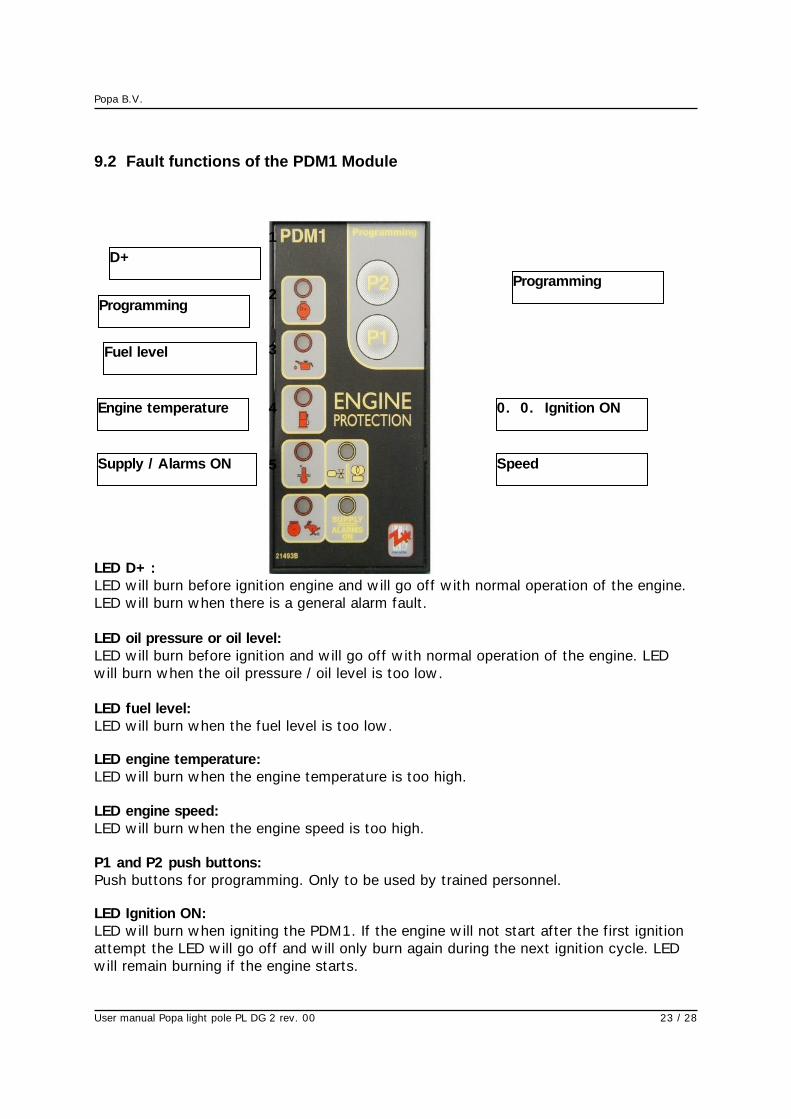
9.2 Fault functions of the PDM1 Module
LED D+ :
LED w ill burn before ignit ion engine and w ill go off w ith normal operat ion of the engine.
LED w ill burn w hen there is a general alarm fault .
LED oil pressure or oil level:
LED w ill burn before ignit ion and w ill go off w ith normal operat ion of the engine. LED
w ill burn w hen the oil pressure / oil level is too low .
LED fuel level:
LED w ill burn w hen the fuel level is too low .
LED engine temperature:
LED w ill burn w hen the engine temperature is too high.
LED engine speed:
LED w ill burn w hen the engine speed is too high.
P1 and P2 push buttons:
Push buttons for programming. Only to be used by trained personnel.
LED Ignition ON:
LED w ill burn w hen ignit ing the PDM1. If the engine w ill not start af ter the f irst ignit ion
attempt the LED w ill go off and w ill only burn again during the next ignit ion cycle. LED
w ill remain burning if the engine starts.
1
2
3
4
5
6
7
8
D+
Oliedruk/olieniveau
Fuel level
Engine temperature
Speed
Supply / Alarms ON
0. 0. Ignition ON
Programming
Programming
Popa B.V.
User manual Popa light pole PL DG 2 rev. 00 24 / 28
LED SUPPLY / ALARMS ON:
LED w ill burn w hen ignit ion the PDM1. LED w ill f lash once w hen the engine starts. LED
w ill t ransfer to f lash after checking the alarms for the correct operat ion of the engine.
When there is an alarm fault w ith the engine the LED w ill quickly f lash for about 2 0
seconds and w ill cont inue to burn afterw ard.
Remark
Some LEDs (2, 3,4 or 5) cannot be used sometimes, depending on the type of pow er
generator the PDM1 is connected to.
Several malfunct ions are indicated by the f lashing of the red light. By count ing the
number of t imes it comes on, one w ill know the malfunct ion code. Betw een the end and
the start of a new pulse series there is a break of about 3 seconds, and betw een the
individual pulses there is a break of 1 second.
If in doubt, contact the let ter and/or manufacturer:
Details manufacturers:
Popa B.V.
P.O. Box 117
5066 ZJ Moergestel (Holland)
Tel: 0031 (0) 135134032
Mobile: 06 20398762
e-mail: [email protected]

Popa B.V.
User manual Popa light pole PL DG 2 rev. 00 25 / 28
10. Disassembly, removal
The local applicable environmental regulat ions should be taken into account (separate
removal of environmentally damaging substances). This is in part icular valid for the
hydraulic oil. (See the appropriate product data sheets)
Disassembly should be done in reversed order of the assembly.

Popa B.V.
User manual Popa light pole PL DG 2 rev. 00 26 / 28
11. Schedules, drawings, pictures
The follow ing schedules and draw ings w ill be provided:
Construct ion draw ings operat ion cabinet
Electronic schedules
Hydraulic schedules

Popa B.V.
User manual Popa light pole PL DG 2 rev. 00 27 / 28
12. Conformity statements
EG-STATEMENT OF CONFORMITY
conform Attachment II (A) Installed installat ion/machinery
Manufacturer : Popa B.V.
Address : P.O. Box 117
5066 ZJ Moergestel (Holland)
Telephone : 0031 (0) 135134032
Mobile : 0031 (0) 6 20398762
Mail [email protected]
declare herew ith that the Popa light pole PL DG 2
- complies w ith the provisions of the Machinery guidelines 2006/42/EG;
- complies w ith the provisions of the EMC guideline 2004/108/EG
- complies, if applicable, w ith the NEN-EN 60204-1
Mr. John van Poppel is responsible for the composit ion of the Technical Construct ion
Dossier.
Place: Moergestel, Date 22 - 02 - 2016
Signature .........................................
Name John van Poppel
Funct ion Director

Popa B.V.
User manual Popa light pole PL DG 2 rev. 00 28 / 28
13. Attachments
EUROPOWER MANUAL EP8DE-EP9TDE-EP183TDE
EUROPOWER MANUAL IB PROTECTOR
EUROPOWER MANUAL AUTOMATIC START / STOP MODULE PDM1