user manual - peak scientific
TRANSCRIPT
NG3000-5000 User Manual Rev 2 RSID 197 06/10/21
NG3000(A) & 5000(A) User Manual

Contents
Change History 3How to use this Manual 3Introduction 4Warranties and Liabilities 5Safety Notices 6Symbols 6Safety Notice to Users 6Declaration of Conformity 7Environmental Declaration 8Technical Specification 9Unpacking 13Installation 14Generator Environment 14Removing the generator from the shipping crate 15Generator Overview 16General Dimensions 16Removal of Transit Brackets 17Wall Mounting 18Rear Connections 19Electrical Connection 20Fuse 20Start-Up Sequence 21Normal Operation 22Unusual Operation 22Service Requirements 23Service Schedule 23Peak Protected 24Cleaning 25
Page 2

Page 3
Change HistoryRev Comment Name Date
How to use this Manual
This manual is intended for end users and has been written as a reference document where you can skip to the relevant information.
Users can refer to the contents page to find the relevant information.
Please review each of the following sections carefully.
Thank you for selecting Peak Scientific to meet your gas generation needs, and should you require any further assistance or support please do not hesitate to contact Peak Scientific or the Peak Partner from which you purchased your generator.
REV 2 Declaration update D.Lai 12/10/2021
Page 4
Introduction
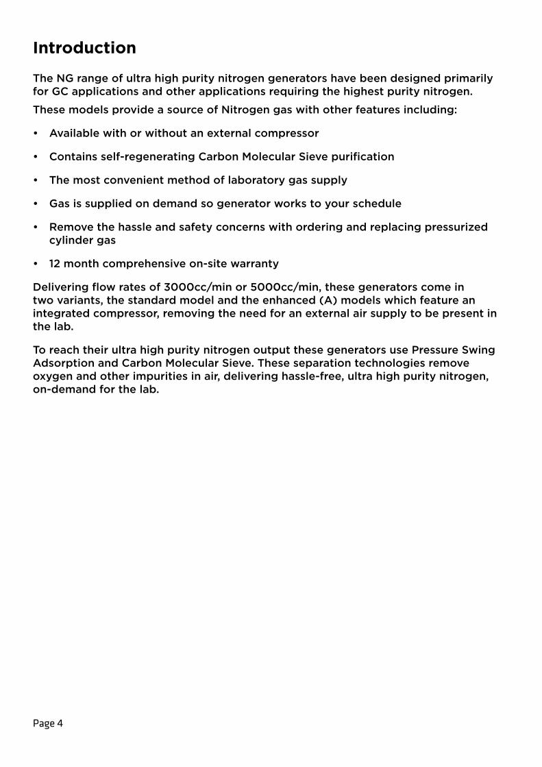
The NG range of ultra high purity nitrogen generators have been designed primarily for GC applications and other applications requiring the highest purity nitrogen.
These models provide a source of Nitrogen gas with other features including:
• Available with or without an external compressor
• Contains self-regenerating Carbon Molecular Sieve purification
• The most convenient method of laboratory gas supply
• Gas is supplied on demand so generator works to your schedule
• Remove the hassle and safety concerns with ordering and replacing pressurized cylinder gas
• 12 month comprehensive on-site warranty
Delivering flow rates of 3000cc/min or 5000cc/min, these generators come in two variants, the standard model and the enhanced (A) models which feature an integrated compressor, removing the need for an external air supply to be present in the lab.
To reach their ultra high purity nitrogen output these generators use Pressure Swing Adsorption and Carbon Molecular Sieve. These separation technologies remove oxygen and other impurities in air, delivering hassle-free, ultra high purity nitrogen, on-demand for the lab.
Page 5
Warranties and Liabilities1. The Company warrants that it has title to the Goods.
2. Subject to the provisions of this clause the Company warrants that the Goods shall comply in all material respects with any specification referred to in the Order Confirmation (as the same may be amended) and shall, subject thereto, be free from defects in material and workmanship for the lesser of a period of twelve months from the date of delivery or thirteen months from the date of dispatch from the factory.
3. Save as provided in this clause and except where the Goods are sold to a person dealing as a consumer (within the meaning of the Unfair Contract Terms Act 1977) all warranties, conditions or other terms implied by statute or common law are hereby expressly excluded save to the extent they may not be lawfully excluded. When the Goods are sold to a consumer within the meaning of the Unfair Contract Terms Act 1977 their statutory rights are not affected by the provisions of this clause.
4. In the event of the Customer making a claim in respect of any defect in terms of clause 2 hereof the Customer must. 1. Reasonably satisfy the Company that the Goods have been properly installed, commissioned, stored, serviced and used and without prejudice to the generality of the foregoing that any defect is not the direct or indirect result of lack of repair and/or servicing, incorrect repair and/or servicing, use of wrong materials and/or incorrect spare parts 2. Allow the company to inspect the Goods and/or any installation and any relevant packaging as and when reasonably required by the Company.
5. Subject to the Company being notified of any defect as is referred to in sub- clause 2 hereof within a reasonable time of it becoming apparent and subject always to the terms of sub-clause 4 hereof, the Company shall, in its option, replace or repair the defective Goods or refund a proportionate part of the Price. The Company shall have no further liability to the Customer (save as mentioned in sub-clause 6 hereof).
6. The Company shall be liable to indemnify the Customer in respect of any claim for death or personal injury to any person in so far as such is attributable to the negligence or breach of duty of the Company or any failure by the Company to comply with the provisions of sub-clause 2 hereof.
7. Save as provided in sub-clause 2 hereof the Company shall not be liable in respect of any claim by the Customer for costs, damages, loss or expenses (whether direct, indirect, consequential or otherwise) or indemnity in any respect howsoever arising including, but not by way of limitation, liability arising in negligence (other than pursuant to clause 6 above) that may be suffered by the Customer or any third party.
WARNING
WARNING
WARNING
WARNING
CAUTION
Page 6
Safety NoticesPeak Scientific Instruments cannot anticipate every possible circumstance which may represent a potential hazard. The warnings detailed within this manual refer to the most likely potential hazards, but by definition cannot be all inclusive. If the user employs an operating procedure, item of equipment or a method of working which is not specifically recommended by Peak Scientific, the user must ensure that the equipment will not be damaged or become hazardous to persons or property.
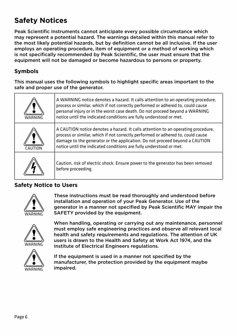
Symbols
This manual uses the following symbols to highlight specific areas important to the safe and proper use of the generator.
A WARNING notice denotes a hazard. It calls attention to an operating procedure, process or similar, which if not correctly performed or adhered to, could cause personal injury or in the worst case death. Do not proceed beyond a WARNING notice until the indicated conditions are fully understood or met.
A CAUTION notice denotes a hazard. It calls attention to an operating procedure, process or similar, which if not correctly performed or adhered to, could cause damage to the generator or the application. Do not proceed beyond a CAUTION notice until the indicated conditions are fully understood or met.
Caution, risk of electric shock. Ensure power to the generator has been removed before proceeding.
Safety Notice to Users
These instructions must be read thoroughly and understood before installation and operation of your Peak Generator. Use of the generator in a manner not specified by Peak Scientific MAY impair the SAFETY provided by the equipment.
When handling, operating or carrying out any maintenance, personnel must employ safe engineering practices and observe all relevant local health and safety requirements and regulations. The attention of UK users is drawn to the Health and Safety at Work Act 1974, and the Institute of Electrical Engineers regulations.
If the equipment is used in a manner not specified by the manufacturer, the protection provided by the equipment maybe impaired.
No. 2 EU DOC

No. 2 EU DOCEU Declaration of Conformity
We Peak Scientific Instruments Ltd.
Of Fountain Crescent, Inchinnan, Renfrewshire, PA4 9RE
Hereby declare that, this declaration of conformity is issued under the sole responsibility of the manufacturer.
Equipment: Nitrogen Generator
Models: NG*000(A) Series * Denotes any numeric value. (A) Denotes compressor based model. To which this declaration relates, is in conformity with the following applicable EU Directives, harmonized standards, and other normative requirements.
• Low Voltage Directive 2014/35/EU EN 61010-1: 2010 Safety Requirements for Electrical Equipment for Measurement, Control and Laboratory Use.
• Electromagnetic Compatibility Directive 2014/30/EU EN 61326-1: 2013 Electrical Equipment for Measurement, Control and Laboratory Use – EMC Requirements. (Class A)
• Restriction on the use of certain hazardous substances in electronic equipment (RoHS) Directive 2011/65/EU as amended by EU 2015/863.
• FCC 47 CFR Part 15 class A Unintentional radiators; Conducted and Radiated emissions limits.
Signed for and on behalf of Peak Scientific by
Signed:
Name: Fraser Dunn
Position: Design Engineering Manager
Peak Scientific Instruments ltd,
Inchinnan, Renfrew, Scotland, PA4 9RE, UK.
Date: 10th August 2021
No. 6 EU PED DOCUK Declaration of Conformity
We Peak Scientific Instruments Ltd.
Of Fountain Crescent, Inchinnan, Renfrewshire, PA4 9RE
Hereby declare that, this declaration of conformity is issued under the sole responsibility of the manufacturer.
Equipment: Nitrogen Generator
Models: NG*000(A) Series * Denotes any numeric value. (A) Denotes compressor based model. To which this declaration relates, is in conformity with the following applicable UK Statutory Instruments, Standards and other normative requirements.
• The Electrical Equipment (Safety) Regulations 2016 (SI 2016 / 1101) as amended. BS61010-1:2010 Safety Requirements for Electrical Equipment for Measurement Control and Laboratory Use.
• The Electromagnetic Compatibility Regulations 2016 (SI 2016 / 1091) as amended. BS61326-1:2013 Electrical Equipment for Measurement , Control and Laboratory Use – EMC Requirements.
• The Restriction of the Use of Certain Hazardous Substances in Electrical and Electronic Equipment Regulations 2012 (SI 2012 / 3032) as amended.
Signed for and on behalf of Peak Scientific by
Signed:
Name: Fraser Dunn
Position: Design Engineering Manager
Peak Scientific Instruments ltd,
Inchinnan, Renfrew, Scotland, PA4 9RE, UK.
Date: 10th August 2021
No. 3 UK DOC

No. 6 EU PED DOCWEEE Compliance Statement
The Waste Electrical and Electronic Equipment (WEEE) Regulations SI 2013 No 3113 and or the Waste Electrical and Electronic Equipment (WEEE) Directive 2012/19/EU apply to all electrical and electronic equipment placed on the market in the UK and EU covered by the scope of regulations which can be found in the Government Guidance Notes (PDF) produced by the Department for Business Innovation and skills for the UK and here for Europe.
All PEAK products that are subject to the WEEE directive are compliant with the WEEE marking requirement. Such products are marked with the “crossed-out wheelie bin” symbol (shown below) in accordance with European standard EN50419. All old electrical equipment can be recycled. Please do not dispose of any electrical equipment (including those marked with this symbol) in general rubbish bins. Please contact your dealer or distributor for clarity.
No. 3 UK DOC
Page 10
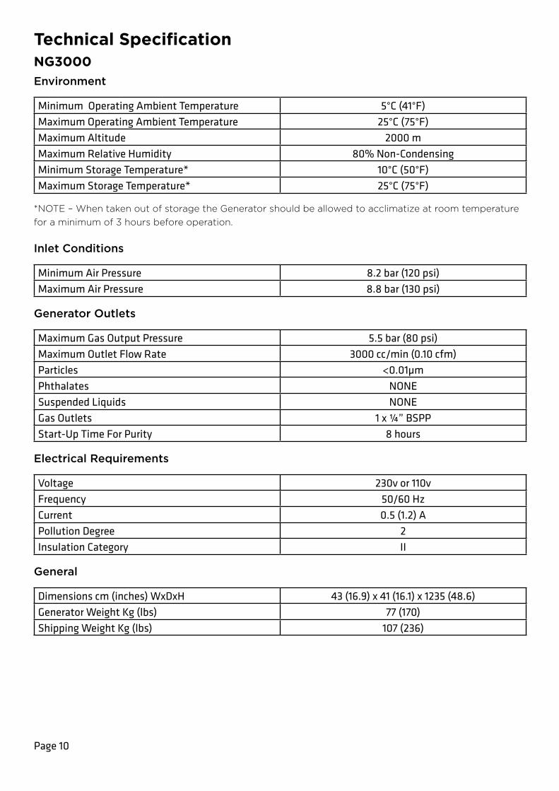
Technical SpecificationNG3000Environment
Minimum Operating Ambient Temperature 5°C (41°F)Maximum Operating Ambient Temperature 25°C (75°F)Maximum Altitude 2000 mMaximum Relative Humidity 80% Non-CondensingMinimum Storage Temperature* 10°C (50°F)Maximum Storage Temperature* 25°C (75°F)
*NOTE – When taken out of storage the Generator should be allowed to acclimatize at room temperature for a minimum of 3 hours before operation.
Inlet Conditions
Minimum Air Pressure 8.2 bar (120 psi)Maximum Air Pressure 8.8 bar (130 psi)
Generator Outlets
Maximum Gas Output Pressure 5.5 bar (80 psi)Maximum Outlet Flow Rate 3000 cc/min (0.10 cfm)Particles <0.01µmPhthalates NONESuspended Liquids NONEGas Outlets 1 x ¼” BSPPStart-Up Time For Purity 8 hours
Electrical Requirements
Voltage 230v or 110vFrequency 50/60 HzCurrent 0.5 (1.2) APollution Degree 2Insulation Category II
General
Dimensions cm (inches) WxDxH 43 (16.9) x 41 (16.1) x 1235 (48.6)Generator Weight Kg (lbs) 77 (170)Shipping Weight Kg (lbs) 107 (236)
Page 11
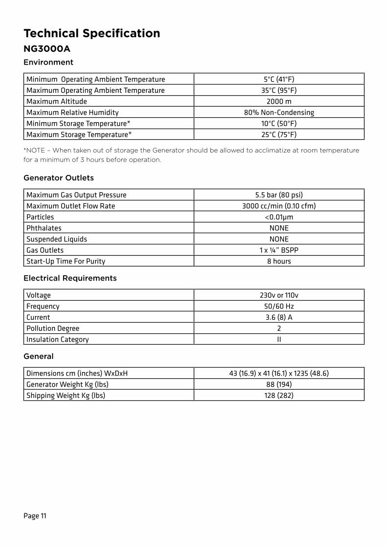
Technical SpecificationNG3000AEnvironment
Minimum Operating Ambient Temperature 5°C (41°F)Maximum Operating Ambient Temperature 35°C (95°F)Maximum Altitude 2000 mMaximum Relative Humidity 80% Non-CondensingMinimum Storage Temperature* 10°C (50°F)Maximum Storage Temperature* 25°C (75°F)
*NOTE – When taken out of storage the Generator should be allowed to acclimatize at room temperature for a minimum of 3 hours before operation.
Generator Outlets
Maximum Gas Output Pressure 5.5 bar (80 psi)Maximum Outlet Flow Rate 3000 cc/min (0.10 cfm)Particles <0.01µmPhthalates NONESuspended Liquids NONEGas Outlets 1 x ¼” BSPPStart-Up Time For Purity 8 hours
Electrical Requirements
Voltage 230v or 110vFrequency 50/60 HzCurrent 3.6 (8) APollution Degree 2Insulation Category II
General
Dimensions cm (inches) WxDxH 43 (16.9) x 41 (16.1) x 1235 (48.6)Generator Weight Kg (lbs) 88 (194)Shipping Weight Kg (lbs) 128 (282)

Page 12
Technical SpecificationNG5000Environment
Minimum Operating Ambient Temperature 5°C (41°F)Maximum Operating Ambient Temperature 25°C (75°F)Maximum Altitude 2000 mMaximum Relative Humidity 80% Non-CondensingMinimum Storage Temperature* 10°C (50°F)Maximum Storage Temperature* 25°C (75°F)
*NOTE – When taken out of storage the Generator should be allowed to acclimatize at room temperature for a minimum of 3 hours before operation.
Inlet Conditions
Minimum Air Pressure 8.2 bar (120 psi)Maximum Air Pressure 8.8 bar (130 psi)
Generator Outlets
Maximum Gas Output Pressure 5.5 bar (80 psi)Maximum Outlet Flow Rate 5000 cc/min (0.17 cfm)Particles <0.01µmPhthalates NONESuspended Liquids NONEGas Outlets 1 x ¼” BSPPStart-Up Time For Purity 8 hours
Electrical Requirements
Voltage 230v or 110vFrequency 50/60 HzCurrent 0.5 (1.2) APollution Degree 2Insulation Category II
General
Dimensions cm (inches) WxDxH 43 (16.9) x 41 (16.1) x 1235 (48.6)Generator Weight Kg (lbs) 77 (170)Shipping Weight Kg (lbs) 107 (236)

Page 13
Technical SpecificationNG5000AEnvironment
Minimum Operating Ambient Temperature 5°C (41°F)Maximum Operating Ambient Temperature 35°C (95°F)Maximum Altitude 2000 mMaximum Relative Humidity 80% Non-CondensingMinimum Storage Temperature* 10°C (50°F)Maximum Storage Temperature* 25°C (75°F)
*NOTE – When taken out of storage the Generator should be allowed to acclimatize at room temperature for a minimum of 3 hours before operation.
Generator Outlets
Maximum Gas Output Pressure 5.5 bar (80 psi)Maximum Outlet Flow Rate 5000 cc/min (0.17 cfm)Particles <0.01µmPhthalates NONESuspended Liquids NONEGas Outlets 1 x ¼” BSPPStart-Up Time For Purity 8 hours
Electrical Requirements
Voltage 230v or 110vFrequency 50/60 HzCurrent 3.6 (8) APollution Degree 2Insulation Category II
General
Dimensions cm (inches) WxDxH 43 (16.9) x 41 (16.1) x 1235 (48.6)Generator Weight Kg (lbs) 88 (194)Shipping Weight Kg (lbs) 128 (282)

Page 14
UnpackingAlthough Peak Scientific takes every precaution with safe transit and packaging, it is advisable to fully inspect the unit for any sign of transit damage.
Check ‘SHOCKWATCH’ and ‘TIP-N-TELL’ labels for signs of rough handling prior to unpacking.
Any damage should be reported immediately to the carrier and Peak Scientific or the Peak Partner from where the unit was purchased.
Follow the unpacking instructions posted on the side of the crate. It will require two people to remove the unit from the shipping crate and to manoeuvre the generator to the desired location.
Please save the product packaging for storage or future shipment of the generator.
Note: Included with the generator is a “Fittings Kit” containing mains power leads for UK, EU & US and also all the required fittings and warranty registration card. Be careful not to discard these with the packaging.
Page 14

Page 15
InstallationGenerator Environment
The generator is designed for indoor use only. It should be installed adjacent to the application(s) it is supplying. If this is not convenient then the unit can be sited elsewhere, however, consideration should be made of the lengths of pipe runs as pressure drops can result from extended runs of pipe.
Performance of the generator (like all sophisticated equipment) is affected by ambient conditions. Note should also be taken to the proximity of Air Conditioning outlets. These can sometimes give rise to “pockets” of air with high relative humidity. Operation of the unit within such a pocket could adversely affect its performance. Consideration should also be given to the air flow around the unit. It is recommended that an air gap of 75mm (3”) should be maintained down both sides and at the rear of the unit. Please refer to the drawing below for the general dimensions of the unit.
Minimum Operating Ambient Temperature: 5 °C (41 °F)
Maximum Operating Ambient Temperature: 35 °C (95 °F)

Page 16
Removing the generator from the shipping crate The generator weighs over 57kg and as such should be unpacked by two people using the following method.
All the screws encircled in RED should first be removed from the shipping crate, there are approximately 16 screws, and the front door should then be removed.
Now, with someone positioned at either side of the shipping crate, the top half of the crate can be slid backwards and away from the rest of the crate. With the top of the crate removed the foam insert of top of the generator should also be taken off.
The generator can now be lifted out of the crate base and onto the floor. This should be done again with someone positioned at either side. There is a gap in the foam base for hand access, one hand should be positioned here underneath the generator and the other at the back supporting the weight. The generator should then be tilted back slightly and then up and out of the foam base and onto the floor.

Page 17
Generator OverviewGeneral Dimensions
The generator must always be placed on a flat, level surface. Failure to do so will affect the performance of the generator.
WARNING
430.00 mm 410.00 mm
1235.00 mm

Page 18
Removal of Transit Brackets The transit brackets must be removed prior to switching the unit on. Failure to do so will result in damage to the equipment. This will void the warranty on the Generator and will result in a chargeable repair.
To remove the transit bracket first remove the 11 screws on the front panel as shown, then remove the front panel from the generator.
Now locate the red transit bracket attached to the compressor foot plate, and remove the two screws on the bracket. Next remove the transit bracket by first lifting up and then out of the generator.
Replace the front panel and secure it to the generator using the 11 screws that were previously removed.
CAUTION

Page 19
Wall Mounting
The NG range generator is designed to be mounted against a wall for safety reasons.
Supplied in the generator fittings kit are all the fittings required to wall mount the generator. Detailed below are the necessary steps to mount the unit to a wall.
Locate the screw in the top rear corner of the unit, beside the yellow warning label. Remove the screw from the generator this should be repeated for the other side of the unit, and retain.
Next, using the screw which was removed, fit the bracket and washers provided to the generator. Again this should be repeated for the other side. The bracket is adjustable to accommodate varying kickboard widths.
Finally, using the dimensions provided, fix the wall plugs to the wall, ensuring wall plug is suitable for the type of wall. If not, use the correct type. Secure the generator to the wall with the screws from the fittings kit.
Page 20
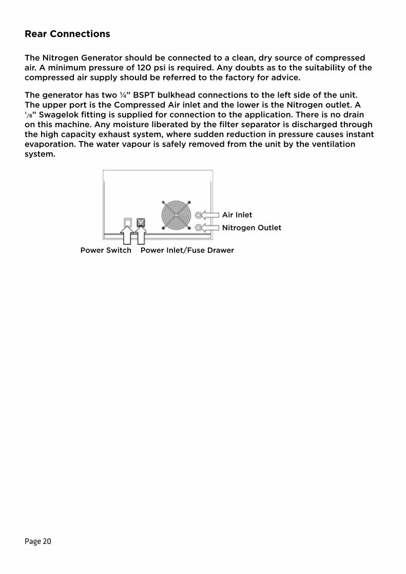
Rear Connections The Nitrogen Generator should be connected to a clean, dry source of compressed air. A minimum pressure of 120 psi is required. Any doubts as to the suitability of the compressed air supply should be referred to the factory for advice.
The generator has two ¼” BSPT bulkhead connections to the left side of the unit. The upper port is the Compressed Air inlet and the lower is the Nitrogen outlet. A ¹/8” Swagelok fitting is supplied for connection to the application. There is no drain on this machine. Any moisture liberated by the filter separator is discharged through the high capacity exhaust system, where sudden reduction in pressure causes instant evaporation. The water vapour is safely removed from the unit by the ventilation system.
Air Inlet
Nitrogen Outlet
Power Switch Power Inlet/Fuse Drawer

Page 21
WARNING
Electrical ConnectionConnect the generator to an appropriate 110 or 230 volt single-phase supply, refer to the generator serial plate for input specification and ensure your supply matches the requirements.
If the appropriate power cord is not supplied; a new plug, rated to at least 12 amps, can be fitted by a qualified electrician.
This unit is classified as SAFETY CLASS 1. THIS UNIT MUST BE EARTHED. Before connecting the unit to the mains supply, please check the information on the serial plate. The mains supply must be of the stated AC voltage and frequency.
EARTH/GROUND (E):- Green & Yellow or Green
LIVE (L):- Brown or Black
Neutral (N):- Blue or White
Electrical requirements are 110 or 230VAC nominal +/- 10% depending on chosen model. However, running continuously at voltages outwith this is not recommended. Extended periods at extremes can have a detrimental effect on the operation and life of the generator.
Fuse
The generator protection fuse, in the pull out drawer of the mains inlet IEC connector located adjacent to the off/on switch. The replacement fuse must be rated T10AH250V
Page 22
Start-Up SequenceBefore the Generator is connected to the application, the Generator should be operated in isolation (i.e. not connected to the application) for thirty minutes. This is to ensure any impurities present are purged from the system. Failure to do this may harm the application.
With the generator installed as described earlier, connect power to the unit and turn it on. Disconnect the Nitrogen outlet connection to allow the generator to vent to atmosphere until the unit is stabilised. At Switch-on the exhaust valve will open and the generator will commence its venting cycle. This is to allow venting of any residual pressure in the system. The vent cycle may last up to 90 seconds. At the end of the vent cycle, the inlet valve will open and the normal operating cycle will begin. Pressure should begin to build on the gauge on the front panel, reaching 80 psi after approximately 10 minutes.
The generator has been pre-set in the factory to give the specified output flow rate and pressure. Once the pressure in the Nitrogen receiver exceeds that setting the generator will stabilise and produce pure Nitrogen. Maximum purity will be achieved after around 8 hours. After this time the generator can be reconnected to the application.
The design of the generator is such that it will deliver up to the rated output flow of Nitrogen at 80 psi. Should the demand for Nitrogen be less than the rated output flow, or indeed should the demand stop, the generator will continue to operate without any problems. The generator is protected from over-pressure and its normal operating cycle ensures frequent venting.
CAUTION

Page 23
Normal OperationThe High Purity Nitrogen Generator utilizes a ‘Pressure Swing Adsorption’ (PSA) method to extract pure Nitrogen from air. This is where un-wanted gasses can be selectively adsorbed from compressed air into a porous carbon molecular sieve material (CMS). The Peak Scientific Instruments LTD. Generator utilizes a unique single column system where the column is alternately pressurised and vented under a finely tuned timing cycle. The rates of pressurisation and venting are accurately set which guarantees high purity better than can be achieved with a similarly sized traditional 2-column system.
Unusual OperationIf at any time the generator begins to emit excessive noise or vibration, then it should be switched off and you should contact Peak Scientific or the Peak Partner from which the generator has been purchased.
Page 24
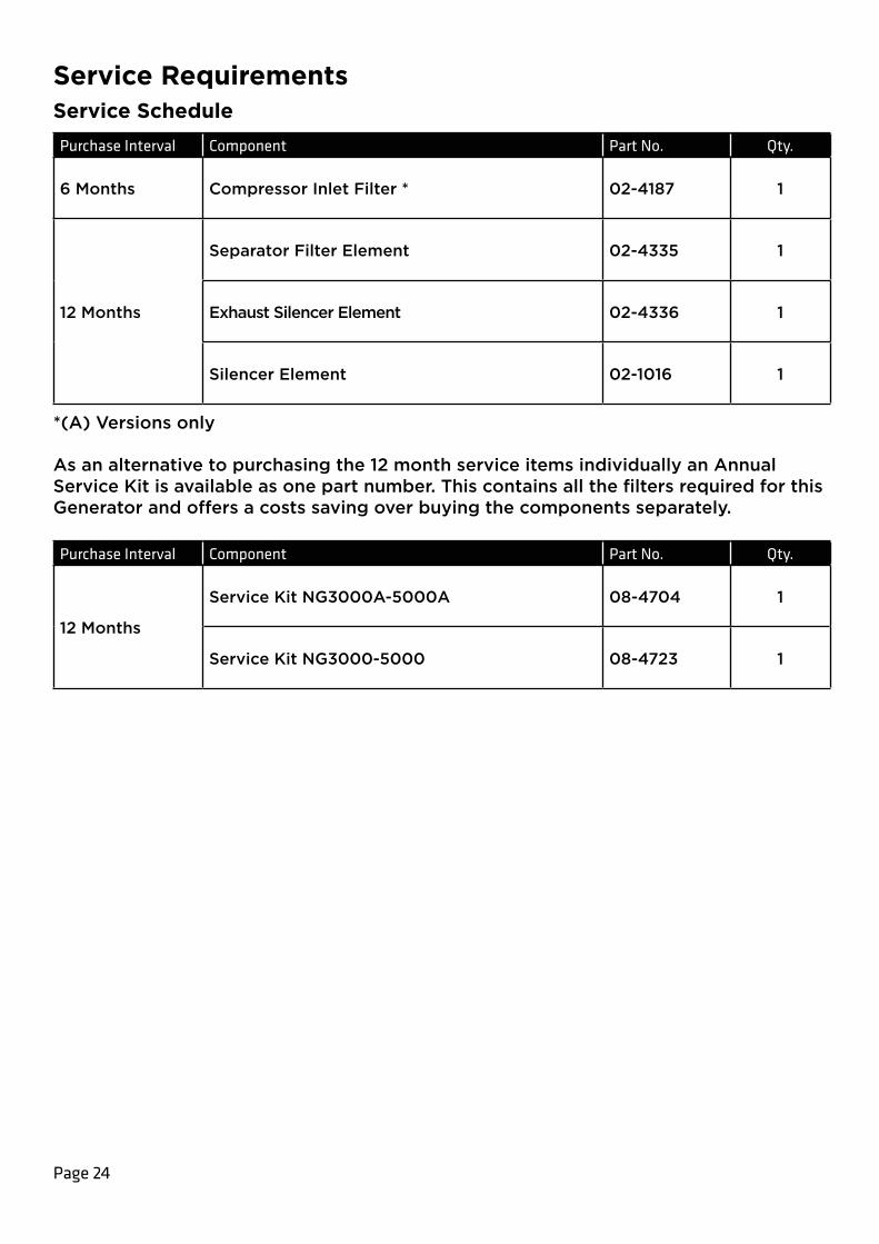
Service RequirementsService SchedulePurchase Interval Component Part No. Qty.
6 Months Compressor Inlet Filter * 02-4187 1
12 Months
Separator Filter Element 02-4335 1
Exhaust Silencer Element 02-4336 1
Silencer Element 02-1016 1
*(A) Versions only
As an alternative to purchasing the 12 month service items individually an Annual Service Kit is available as one part number. This contains all the filters required for this Generator and offers a costs saving over buying the components separately.
Purchase Interval Component Part No. Qty.
12 Months
Service Kit NG3000A-5000A 08-4704 1
Service Kit NG3000-5000 08-4723 1
Page 25
Peak ProtectedWith Peak Scientific you invest in not only a product but peace of mind. With a network of certified Peak engineers stationed throughout the globe, Peak’s rapid response team are never far away and our commitment is to keep your generator running day in, day out, protecting your laboratory workflow.
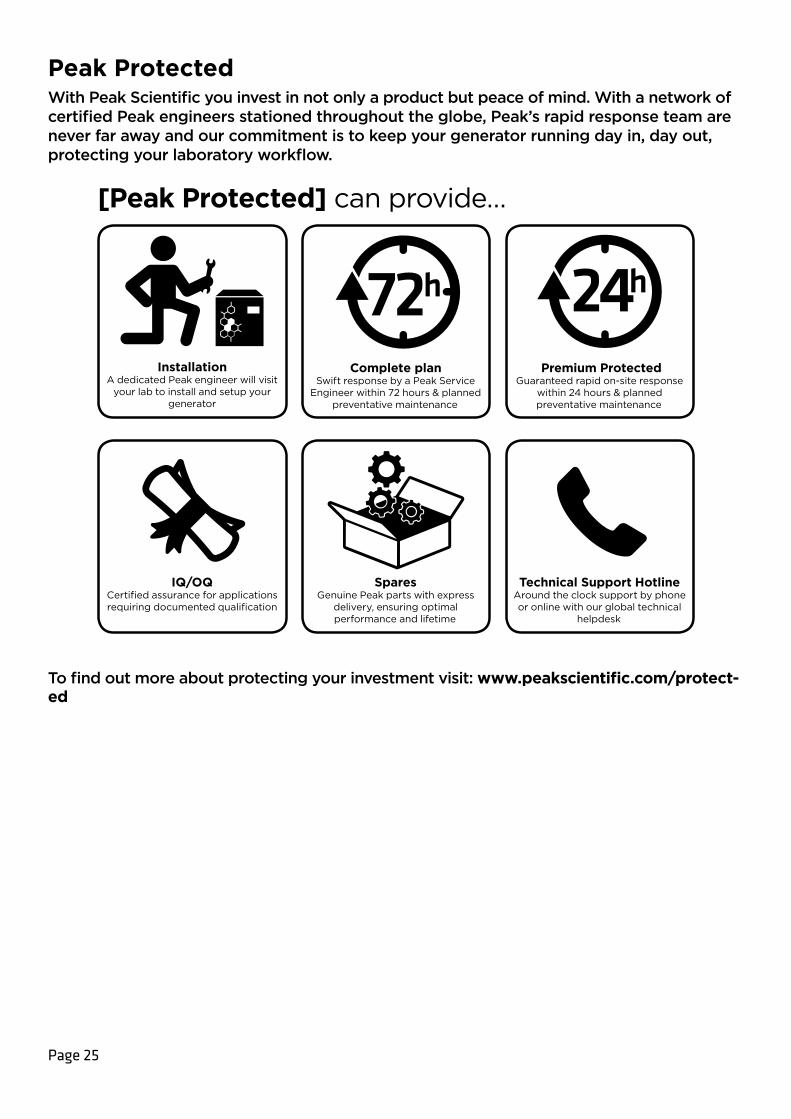
[Peak Protected] can provide…
Installation A dedicated Peak engineer will visit
your lab to install and setup your generator
IQ/OQCertified assurance for applications requiring documented qualification
Complete planSwift response by a Peak Service
Engineer within 72 hours & planned preventative maintenance
SparesGenuine Peak parts with express
delivery, ensuring optimal performance and lifetime
Premium ProtectedGuaranteed rapid on-site response
within 24 hours & planned preventative maintenance
Technical Support HotlineAround the clock support by phone or online with our global technical
helpdesk
To find out more about protecting your investment visit: www.peakscientific.com/protect-ed

Page 26
CleaningClean the outside of the generator only using warm soapy water and a clean damp cloth. Ensure all excess fluid is thoroughly removed from the cloth prior to use.
Cleaning should only be undertaken with the power switched off and the power cord removed from the rear of the generator.
Under no circumstances should any solvents or abrasive cleaning solutions be used as these can contain fumes that could be harmful to the generator.
Care should be taken with Leak Detection Liquids.
CAUTION
CAUTION

Page 27
Go Online or Complete and ReturnYou can register for your FREE 12 month Warranty with ease online at www.peakscientific/protected.
Alternatively, you can send the completed form to Peak Scientific by post or email at [email protected].
Product Warranty RegistrationContact name
Email address
Company
Address
City/town
Postcode
Country
Telephone
Generator serial #
Model type
Installation date
Do you still use an alternative gas solution i.e. cylinders or bulk liquid?
Yes No
What gas requirements do you have in your lab? Hydrogen Nitrogen Zero Air
Extend your cover withPeak Scientific offer comprehensive gas generator after sales support packages. Peak [Protected] aftercare support can guarantee an on-site response within 72 hours*, genuine parts from our ISO9001 approved factory and a 95% first-time fix rate. See our enclosed Peak [Protected] leaflet for further information.Important!You have 1 month to register your Peak Scientific product from the date of installation. Once registered the warranty will be honoured for a period of 12 months. If you wish to defer the installation of your generator, you must notify Peak Scientific immediately by emailing [email protected]. For generators that remain unregistered after 1 month from the shipment date, the warranty will be considered active from the date of factory dispatch.
* Complete Plan only
Go Online or Complete and ReturnWe know that registering any of your recently purchased products is not the first thing on your mind- but it is very important to both of us. Not all warranties are alike and Peak Scientific stand out against other gas suppliers as we offer a comprehensive, quick response, on-site warranty. This means that in the very unlikely case that your gas generator develops a fault we have rapid support teams on-hand around the world who are able to come to your lab and get you back up and running in no time.
Register for your comprehensive 12 month on-site warranty with ease online at www.peakscientific.com/protected.
Alternatively, you can send the completed form to Peak Scientific by post or email at [email protected].
Important!You have 1 month to register your Peak Scientific product from the date of installation. Once registered the warranty will be honoured for a period of 12 months. If you wish to defer the installation of your generator, you must notify Peak Scientific immediately by emailing [email protected]. For generators that remain unregistered after 1 month from the shipment date, the warranty will be considered active from the date of factory dispatch.
For further information on any of our generator products please contact [email protected]
Peak Scientific has highly trained, fully certified Field Service Engineers located in over 20 countries across every continent around the world. This allows us to provide an industry-leading rapid response service to our customers. With [Peak Protected], your laboratory’s productivity becomes our top priority.
To discuss Peak Protected generator cover and payment options speak to your local Peak Representative or for further information contact: [email protected]
NG3000-5000 User Manual Rev 2 RSID 197 06/10/21
Peak ScientificFountain CrescentInchinnan Business ParkInchinnanPA4 9REScotland, UKTel: +44 141 812 8100Fax: +44 141 812 8200