user manual - old.siglentamerica.comold.siglentamerica.com/usa_website_2014/documents/... ·...
TRANSCRIPT

SIGELNT
SPD1000X User Manual 1
User Manual
SPD1000X Programmable Linear DC
Power Supply
UM0501X-E02A
2018 SIGLENT TECHNOLOGIES CO., LTD

SIGLENT
SPD1000X User Manual I
Copyright and Declaration
Copyright
SIGLENT TECHNOLOGIES CO.,LTD. All Right Reserved.
Trademark Information
SIGLENT is a registered trademark of SIGLENT TECHNOLOGIES.
Declaration
SIGLENT products are protected by patent law in and outside of the
People’s Republic of China
.
SIGLENT reserved the right to modify or change the specifications and
price of the product
Information in this publication replace all previous corresponding material
Any copying, extracting or translation of the content of this manual is not
allowed without permission from SIGLENT.

SIGELNT
II SPD1000X User Manual
General Safety Summary
Please review the following safety precautions carefully to avoid personal
injury or damage to this product or any product connected to it. To prevent
potential danger, please use the instrument as specified.
Use the proper power cord
Only the power cord designed for the instrument and authorized by the local
country should be used.
Power supply
AC Input Voltages: 100/120/220/230 V ± 10%,50/60 Hz
Use the proper fuse
The fuse type: 100/120 V: T6.3A/250V
220/230 V : T3.15A/250V
Make sure to use the correct type of fuse before turning on the instrument.
Find the cause of the fuse failure before replacing the fuse and connecting
the power cord.
Ground the instrument
The instrument is grounded through the protective Earth conductor of the
power cord. To avoid electric shock, the grounding conductor must be
connected to the Earth ground. Make sure that the instrument is properly
grounded before any activating any inputs or outputs.
Examine all the terminal ratings

SIGELNT
SPD1000X User Manual III
To avoid fire or electric shock, please examine all ratings and symbols on the
instrument. Read this guide carefully to learn more details about the ratings
before connection.
Keep proper ventilation
Inadequate ventilation may cause an increase of temperature within the
instrument, which can lead to instrument damage. Please maintain proper
ventilation and check the fan and air-vents regularly when using the
instrument.
Operating conditions
Location: indoor, no excessive bright lighting, minimal air pollution
Relative humidity: < 80%
Altitude: < 2000 m
Temperature: 0 ℃ to 40 ℃
Electrostatic Prevention
Operate in an electrostatic discharge protected area environment to avoid
damages induced by static discharges. Always ground both the internal and
external conductors of the cable to remove static before connecting.
Do not operate in an explosive atmosphere
To avoid personal injury or damage to the instrument, please do not operate
in an explosive atmosphere.
Keep surface of the product clean and dry
Avoid dust and moisture in the air as they can influence the performance of
the instrument. Please keep surface of the product clean and dry.
SIGELNT
IV SPD1000X User Manual
Safety Terms and Symbols
Terms may appear on the product:
DANGER: Indicates direct injury or hazard that may occur.
WARNING: Indicates potential injury or hazard that may occur.
CAUTION: Indicates potential damage to the instrument or other property
that may occur.
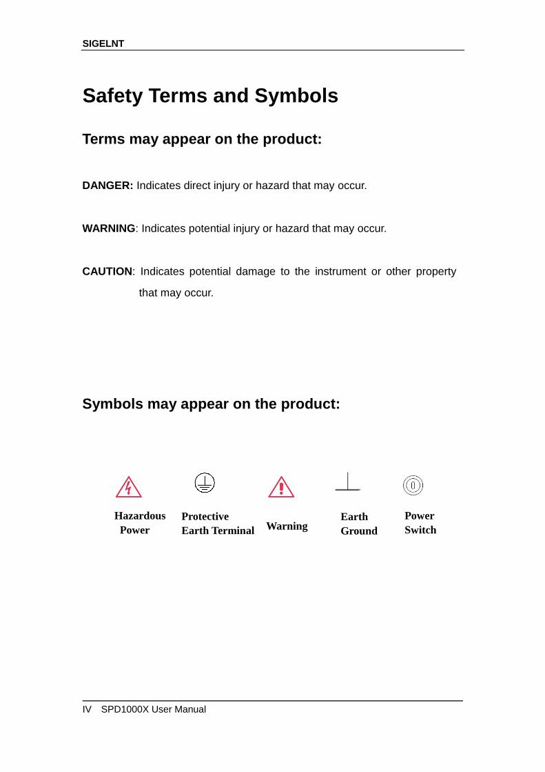
Symbols may appear on the product:
Hazardous
Hazardous
Power
Protective
Earth Terminal Warning Earth
Ground
Power
Switch

SIGELNT
SPD1000X User Manual V
SPD1000X Brief Introduction
The Siglent SPD1000X Programmable DC Power Supply has a 2.8 inch
TFT-LCD screen, programmable output, and real time graphical trending
display. The SPD1168X has maximum output values of 16 V/8 A. The
SPD1305X has maximum output values of 30 V/5 A. Both models provide
remote sensing as well as output short circuit and overload protection. The
SPD1000X is suitable for a variety of applications in research and
development, production and repair.
Main features:
Single high-precision programmable output:
SPD1168X: 16 V/8 A, total power available is 128 W
SPD1305X: 30 V/5 A, total power available is 150 W
Compact and easy to use, ideal for bench power supply
SIGELNT
VI SPD1000X User Manual
Stable, reliable and low noise: ≤ 350 uVrms/3 mVpp
Fast Transient Response Time: < 50 μs
Maximum resolution of 1 mV, 1 mA with 5-digit voltage and 4-digit current
display.
Timer function sequences preset output values
High resolution 2.8 inch TFT LCD (240*320 pixels)
Two output modes: two-wire output and remote sense compensation
function (maximum compensation up to 1 V)
Four input/line voltage selection choices including 100 V, 110 V, 220 V
and 230 V to satisfy different requirements
Intelligent temperature-controlled fan, effectively reduces noise
Bright, clear graphical interface, with waveform display
Five internal system parameter save / recall locations, support for data
storage space expansion
Comes with EasyPower PC software. Real-time control via USB, LAN.
Supports SCPI command set and LabView driver package to meet the
remote control and communication requirements
SIGELNT
SPD1000X User Manual VII
Content
Copyright and Declaration ......................................................................................... I
General Safety Summary .......................................................................................... II
Safety Terms and Symbols ...................................................................................... IV
SPD1000X Brief Introduction ................................................................................... V
Chapter 1 Start Guide ................................................................................................. 1
1.1 General Inspection .................................................................................... 2
1.2 The Front Panel ......................................................................................... 3
1.3 The Rear Panel .............................................................................................. 6
1.4 Connect Power ........................................................................................... 8
1.5 User Interface ........................................................................................... 10
1.6 Output Inspection ..................................................................................... 12
1.7 Fuse Replacement ....................................................................................... 13
Chapter 2 Control panel operation ......................................................................... 14
2.1 Output summary ...................................................................................... 15
2.2 2-wire mode .............................................................................................. 17
2.3 Remote Sense mode .............................................................................. 19
2.4 Configuration of LAN interface .............................................................. 21
2.5 Save and recall ........................................................................................ 23
2.6 Timer .......................................................................................................... 27
2.7 Waveform display .................................................................................... 31
2.8 Version information .................................................................................. 32
2.9 Lock key .................................................................................................... 33
2.10 Upgrade firmware ................................................................................. 34
Chapter 3 Remote control ........................................................................................ 37
3.1 Control method ......................................................................................... 37
3.2 Grammar conventions ............................................................................. 38
3.3 Command Summary ............................................................................... 39
3.4 Command description ............................................................................. 41
3.5 Programming examples .......................................................................... 49
Chapter 4 Common troubleshooting ............................................................................ 61
Chapter 5 Service and Support ............................................................................... 63
5.1 Maintenance summary............................................................................ 63
5.2 Contact SIGLENT .................................................................................... 63

SIGELNT
SPD1000X User Manual 1
Chapter 1 Start Guide
In this chapter, we introduce the front panel and display interface of the
SPD1000X, and also tips for how to check and operate the power supply the
first time.
The main content of Chapter 1 includes:
General Inspection
The front panel
The rear panel
Connecting power
User interface
Output Inspection
Fuse Replacement

SIGELNT
2 SPD1000X User Manual
1.1 General Inspection
Please check the instrument according to the following steps:
1. Inspect the shipping container
Keep the shipping container and cushioning material until the contents of
the shipment have been completely checked and the instrument has
passed both electrical and mechanical tests. The consigner or carrier is
responsible for damages to the instrument resulting from shipment.
SIGLENT will not provide free maintenance or replacement for shipping
damages.
2. Inspect the instrument
If there is damage, defects, or failures in electrical and mechanical tests of
the product, please contact your nearest SIGLENT sales representative.
3. Check the accessories
Please check the accessories according to the packing list. If the
accessories are incomplete or damaged, please contact your
SIGLENT sales representative.
SIGELNT
SPD1000X User Manual 3
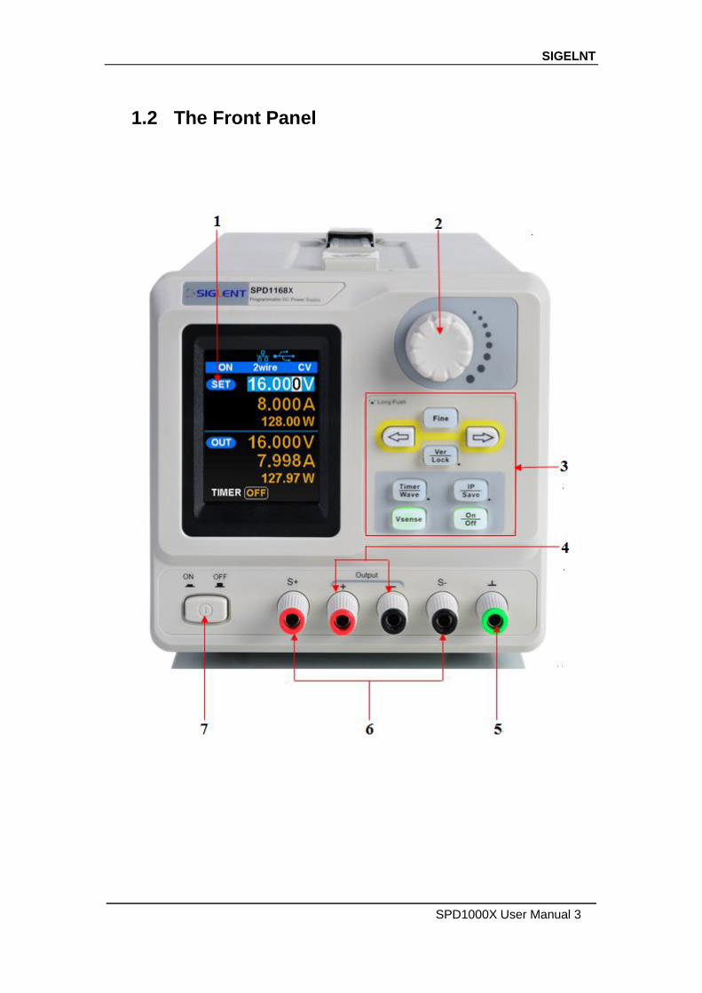
1.2 The Front Panel
SIGELNT
4 SPD1000X User Manual
1. LCD Display
2.8 inch TFT-LCD is used to display system parameter settings, system
output state, menu options, prompt messages, etc.
2. Knob
When setting parameters, rotate the knob to increase or decrease the
value of the digit at the cursor. In the Store Page the knob can be used to
quickly move to the desired file.
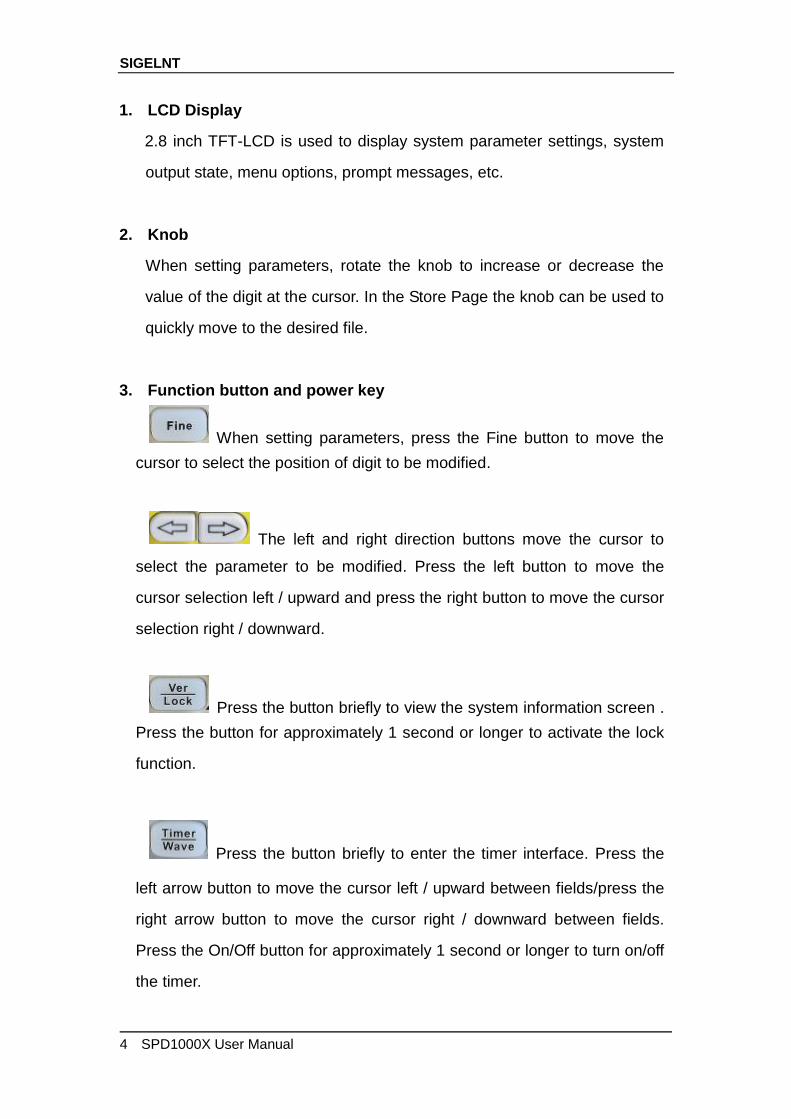
3. Function button and power key
When setting parameters, press the Fine button to move the
cursor to select the position of digit to be modified.
The left and right direction buttons move the cursor to
select the parameter to be modified. Press the left button to move the
cursor selection left / upward and press the right button to move the cursor
selection right / downward.
Press the button briefly to view the system information screen .
Press the button for approximately 1 second or longer to activate the lock
function.
Press the button briefly to enter the timer interface. Press the
left arrow button to move the cursor left / upward between fields/press the
right arrow button to move the cursor right / downward between fields.
Press the On/Off button for approximately 1 second or longer to turn on/off
the timer.
SIGELNT
SPD1000X User Manual 5
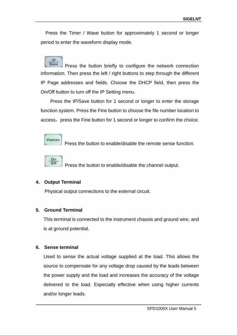
Press the Timer / Wave button for approximately 1 second or longer
period to enter the waveform display mode.
Press the button briefly to configure the network connection
information. Then press the left / right buttons to step through the different
IP Page addresses and fields. Choose the DHCP field, then press the
On/Off button to turn off the IP Setting menu.
Press the IP/Save button for 1 second or longer to enter the storage
function system. Press the Fine button to choose the file number location to
access,press the Fine button for 1 second or longer to confirm the choice.
Press the button to enable/disable the remote sense function.
Press the button to enable/disable the channel output.
4. Output Terminal
Physical output connections to the external circuit.
5. Ground Terminal
This terminal is connected to the instrument chassis and ground wire, and
is at ground potential.
6. Sense terminal
Used to sense the actual voltage supplied at the load. This allows the
source to compensate for any voltage drop caused by the leads between
the power supply and the load and increases the accuracy of the voltage
delivered to the load. Especially effective when using higher currents
and/or longer leads.
SIGELNT
6 SPD1000X User Manual
7. Power key
Turns the instrument on or off.
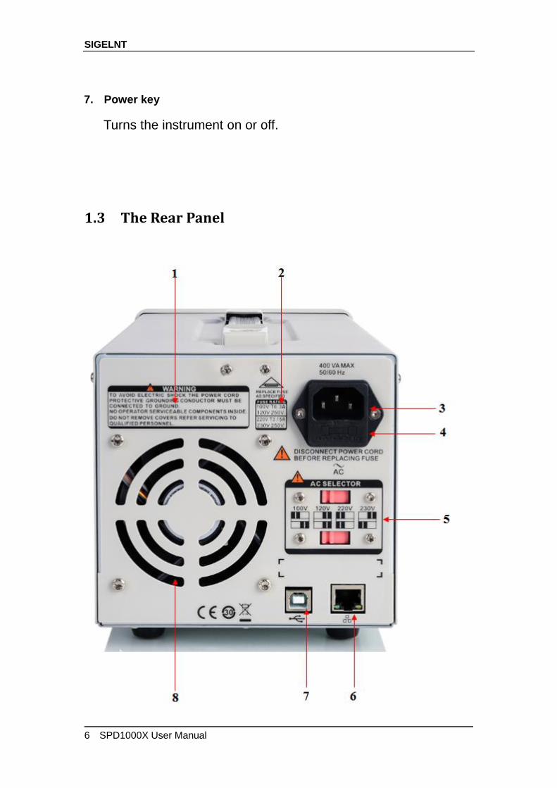
1.3 The Rear Panel
SIGELNT
SPD1000X User Manual 7
1. Warning message
Warning message regarding proper grounding and instrument maintenance.
2. AC input voltage description
The frequency, voltage and the specified fuse should correspond to the AC
input mains.
3. AC power socket
The socket for AC input power.
4. Fuse
The specified fuse must be rated for the input voltage (Please refer to the
“ AC input voltage description “)
5. AC line power selection switch
AC Input Voltages: 100/120/220/230 V
6. LAN interface
RJ45 jack for connection to any user-supplied LAN.
7. USB device
USB-B connector for connection to a user-supplied USB controller.
8. Fan
SIGELNT
8 SPD1000X User Manual
1.4 Connect Power
The power supply supports a variety of AC line power input values. For each
line voltage, the rear panel voltage selector settings are different, as shown in
table 1 below.
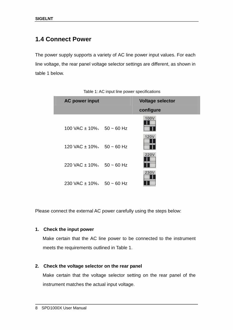
Table 1: AC input line power specifications
AC power input Voltage selector
configure
100 VAC ± 10%, 50 ~ 60 Hz
120 VAC ± 10%, 50 ~ 60 Hz
220 VAC ± 10%, 50 ~ 60 Hz
230 VAC ± 10%, 50 ~ 60 Hz
Please connect the external AC power carefully using the steps below:
1. Check the input power
Make certain that the AC line power to be connected to the instrument
meets the requirements outlined in Table 1.
2. Check the voltage selector on the rear panel
Make certain that the voltage selector setting on the rear panel of the
instrument matches the actual input voltage.
SIGELNT
SPD1000X User Manual 9
3. Check the fuse
When the instrument leaves the factory, the specified fuse is installed.
Please check whether the fuse matches the actual input voltage
according to the "Input Power Requirements" on the rear panel of the
instrument.
4. Connect the power
Connect the instrument to AC power supply using the power cord
provided with the accessories. Then press the button to turn on
the power.
WARNING
Before switching the input power supply voltage, please disconnect the
power supply before setting the voltage selector to the
appropriate setting.
WARNING
To avoid electric shock, make certain that the instrument is correctly
grounded.

SIGELNT
10 SPD1000X User Manual
1.5 User Interface
1. Channel output state
On / Off
2. Remote sense mode
2 wire:two wire mode,4 wire:four wire(remote sense)mode.
3. LAN connection icon
When the instrument is connected to a network through the LAN port
this flag is displayed.
4. USB connection icon
When the instrument is connected to a computer via the USB
SIGELNT
SPD1000X User Manual 11
DEVEICE interface this icon is displayed.
5. Output mode
CV:Constant Voltage,CC:Constant Current.
6. Output programmed values
Voltage,current,power settings
7. Measured output values
Voltage,current,power actual output
8. Timer state
On / Off
SIGELNT
12 SPD1000X User Manual
1.6 Output Inspection
1. Check the output voltage
(1) Turn on the power and make certain the channel current setting is
not zero when the instrument has no-load.
(2) Press on/off button, the supply should be working in constant
voltage (CV) mode. You can check the voltage range of SPD1168X
by adjusting the voltage setpoint from the minimum (0 V) to the
maximum value (16 V) and the voltage range of SPD1305X by
adjusting the voltage setpoint from the minimum (0 V) to the
maximum value (30 V).
2. Check the output current
(1) Turn on the power and make certain the voltage setting is not zero.
(2) Connect the output terminals (short) with an insulated wire that can
handle 10 A or more (18 AWG single core, for example).
(1) Activate the output by pressing the on/off button. The low
impedance (shorted) output will cause the instrument to enter
current control (CC) mode. You can check the current range of the
SPD1168X by adjusting the current setpoint from the minimum (0 A)
to the maximum value (8 A) and the current range of the SPD1305X
by adjusting the current setpoint from the minimum (0 A) to the
maximum value (5 A).

SIGELNT
SPD1000X User Manual 13
1.7 Fuse Replacement
The specifications of the fuse are relative to the actual input line voltage,
shown in the table below. You also can refer to the rear panel “input power
requirement”.
To replace the fuse,please follow the steps below:
1. Turn off the instrument and remove the power cord.
2. Insert a small straight screwdriver into the slot at the power socket
and gently pry out the fuse seat.
3. Adjust the power voltage selector manually to select the correct
voltage scale.
4. Take out the fuse and replace it with the specified fuse (for the
corresponding relationship between the AC input voltage and fuse
specification, refer to the “input power requirement” at the rear
panel).
5. Re-insert the fuse holder into the power socket (please pay attention
to the directions).
WARNING
To avoid personal injuries, unplug the power supply before replacing the
fuse. To avoid electric shock or fire, select the proper power supply
specification and replace only with the proper fuse.
Input voltage Fuse specification
100/120 VAC T6.3A
220/230 VAC T3.15A
SIGELNT
14 SPD1000X User Manual
Chapter 2 Control panel operation
In this chapter, the functions and operation of the SPD1000X control panel will
be introduced in detail.
Brief introduction:
Output summary
Setting the output voltage and current of the power supply
Remote terminal
LAN configuration
Save/recall
Timer
Waveform display
Version information
Lock
Update

SIGELNT
SPD1000X User Manual 15
2.1 Output summary
The SPD1000X provides a floating output. The output rating of the
SPD1168X is 0-16 V / 0-8 A,while the output rating of SPD1305X is 0-30
V / 0-5 A;
Two modes of output: constant voltage (CV) and constant current (CC);
Two types of operation: two wire mode and remote sense mode.
Constant voltage output/constant current output:
In the constant current mode, the output current is a set value which can
be controlled by the front panel. The user interface displays the output mode
is ‘CC’ and the current is still in a set value. At this time, the voltage is lower
than the set value. When the output current is less than the set value, the
constant current mode will switch to constant voltage mode automatically.
In the constant voltage mode, the output current is less than the set value,
which can be controlled by the front panel. The user interface displays the
output mode is ‘CV’ and the voltage remains at the set value. When output
current reaches the set value, the system switches to the constant current
mode.
2-wire mode/remote sense mode:
When the SPD1000X is set to the 2-wire mode, the display prompt
displays the working mode as “2-wire.” When the output is on, the instrument
will detect and display the output terminal’s actual output mode automatically.
In the remote sense mode, the prompt displays the working mode as
“remote sense.” When the output is on and the remote sense terminal
connect to the load, the instrument will detect and display the actual output.

SIGELNT
16 SPD1000X User Manual
SIGELNT
SPD1000X User Manual 17
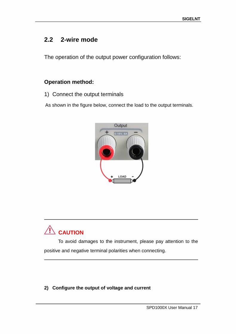
2.2 2-wire mode
The operation of the output power configuration follows:
Operation method:
1) Connect the output terminals
As shown in the figure below, connect the load to the output terminals.
CAUTION
To avoid damages to the instrument, please pay attention to the
positive and negative terminal polarities when connecting.
2) Configure the output of voltage and current
SIGELNT
18 SPD1000X User Manual
a) Selecting the parameters to change by moving the left / right arrow
keys.
b) Press Fine button to select the data’s position, then rotate the knob to
change the parameter.
3) Enable the output
Make certain the mode is 2-wire (the Vsense key is off and the display
shows 2-wire). Press the On/Off button, the button light will light up, the
channel output is enabled and the display shows the power supply
status is "On".
Note: Built-in overvoltage protection; When the actual output voltage of
the SPD1168X is greater than 22 ± 2 V or the actual output voltage of
the SPD1305X is greater than 36 ± 2 V, the output will automatically
short-circuit, and limit the voltage output. If this occurs, please
re-engage the output enable switch to resume normal output.
SIGELNT
SPD1000X User Manual 19
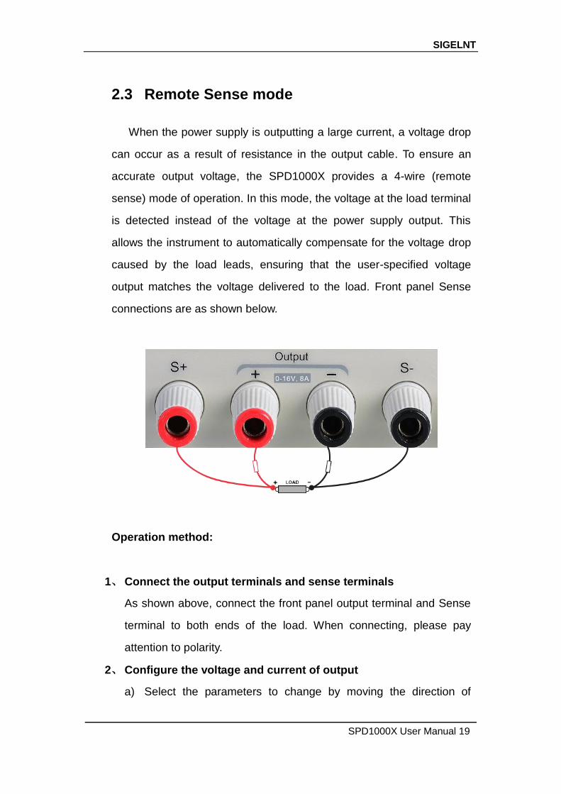
2.3 Remote Sense mode
When the power supply is outputting a large current, a voltage drop
can occur as a result of resistance in the output cable. To ensure an
accurate output voltage, the SPD1000X provides a 4-wire (remote
sense) mode of operation. In this mode, the voltage at the load terminal
is detected instead of the voltage at the power supply output. This
allows the instrument to automatically compensate for the voltage drop
caused by the load leads, ensuring that the user-specified voltage
output matches the voltage delivered to the load. Front panel Sense
connections are as shown below.
Operation method:
1、 Connect the output terminals and sense terminals
As shown above, connect the front panel output terminal and Sense
terminal to both ends of the load. When connecting, please pay
attention to polarity.
2、 Configure the voltage and current of output
a) Select the parameters to change by moving the direction of
SIGELNT
20 SPD1000X User Manual
cursor
b) Press Fine button to select the cursor’s position, then rotate the
knob to adjust the parameter.
3、 Open the 4-wire mode
Press Vsense button, the button will light up. The power supply
screen will show ‘4 wire’ on the display.
4、 Enable the output
Press the on/off button, the button light is lit and the power supply
display shows “on”.
Note: In 4-wire mode, the maximum compensation voltage of the power
supply is 1 V. When the voltage difference between the output terminal
and the Sense terminal is more than 1 V, the instrument will turn off
automatically.

SIGELNT
SPD1000X User Manual 21
2.4 Configuration of LAN interface
The SPD1000X supports USB Device and LAN interfaces. You can
remotely control the SPD1000X through these interfaces. When using the
LAN interface, first set the interface parameters.
Operation methods:
1. Use the network cable to connect the LAN port on the rear panel with
the network where the computer or computers are located;
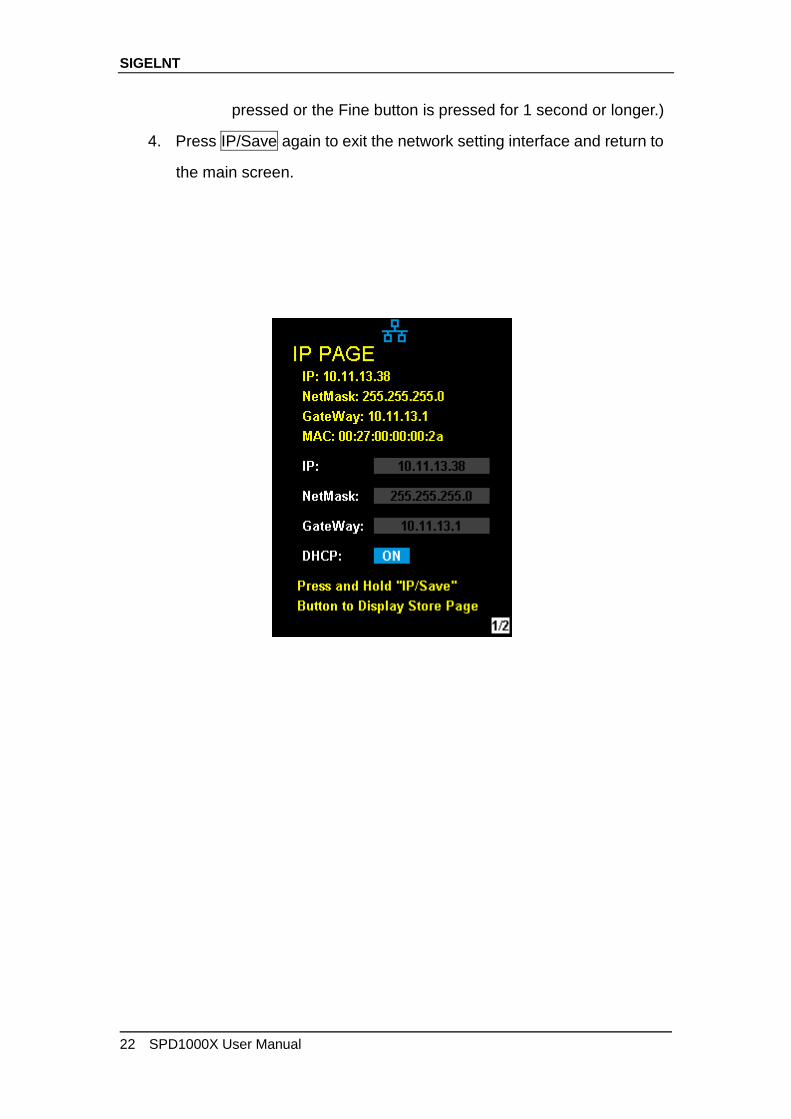
2. Press IP/Save briefly to enter the network setting interface.
3. After setting the IP value, press the multi-function knob or press the
Fine button for 1 second or longer to make the setting effective, then
press the left / right arrow buttons repeatedly to move the cursor to
the DHCP line. Turn the knob to set DHCP to ON or OFF, then press
the multi-function knob or press the On/Off button briefly to turn on/off
the DHCP.
ON: The power will automatically set the IP address, subnet
mask and gateway automatically loaded according to the current
access network.
OFF: The user can set the IP address, subnet mask and
gateway.
Press the left/right arrow button to change the position of
cursor.
Rotate the knob or press the left and right arrow buttons for 1
second or longer to change the data.
Press Fine button to change the highlighted digit.
Press the knob or press the Fine button for a longer period to
save the setting (all settings will take effect only if the knob is
SIGELNT
22 SPD1000X User Manual
pressed or the Fine button is pressed for 1 second or longer.)
4. Press IP/Save again to exit the network setting interface and return to
the main screen.

SIGELNT
SPD1000X User Manual 23
2.5 Save and recall
The SPD1000X allows the user to save the current instrument status
(including operating modes, voltage/current settings, timer parameters, etc.)
to the internal memory and recall saved files when required.
Save
Operation steps:
1. Set the parameter settings to be saved;
2. Press IP/Save for 1 second or longer to enter to the Store Page
screen.
3. Press the direction button to move the cursor to “FILE CHOICE”;
4. Rotate the knob or press the Fine button briefly to select the storage
location (FILE 1~FILE 5);
5. Press the arrow buttons to move the cursor to "OPER CHOICE"
6. Turn the multi-function knob to select "STORE" and press the knob or
press the Fine button for 1 second or longer to select "OK" to save
the current settings. After saving, the corresponding file location will
turn yellow.
SIGELNT
24 SPD1000X User Manual
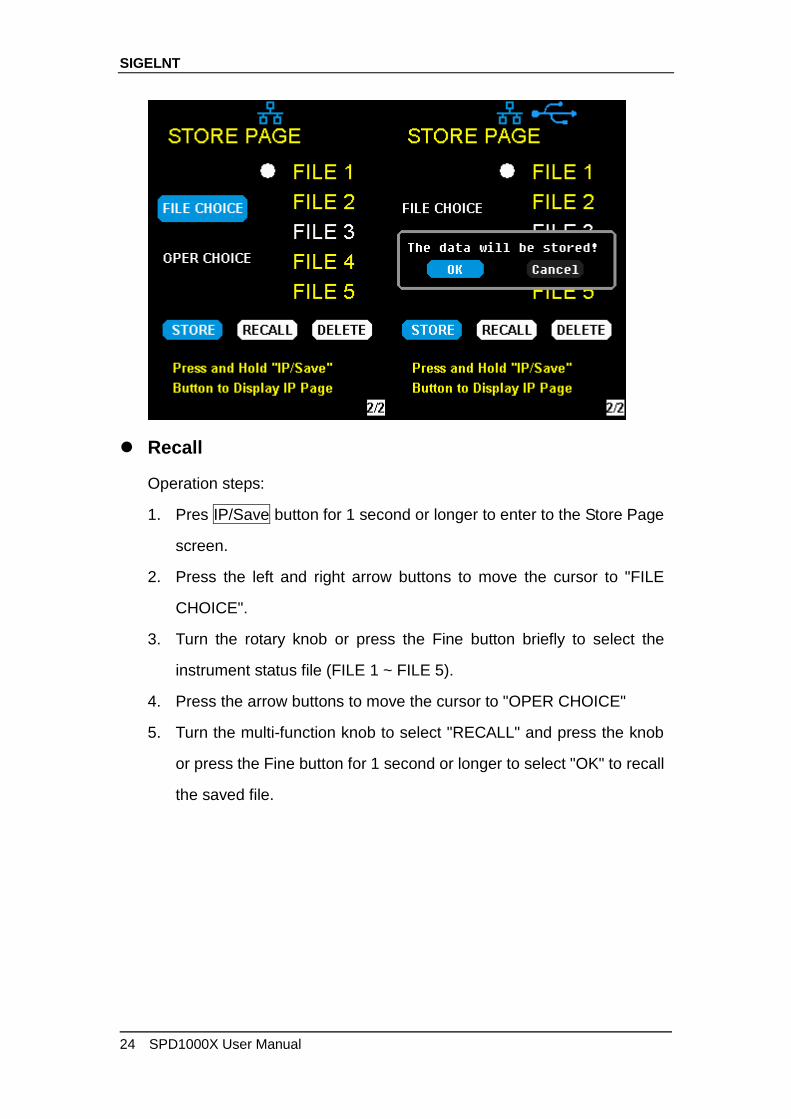
Recall
Operation steps:
1. Pres IP/Save button for 1 second or longer to enter to the Store Page
screen.
2. Press the left and right arrow buttons to move the cursor to "FILE
CHOICE".
3. Turn the rotary knob or press the Fine button briefly to select the
instrument status file (FILE 1 ~ FILE 5).
4. Press the arrow buttons to move the cursor to "OPER CHOICE"
5. Turn the multi-function knob to select "RECALL" and press the knob
or press the Fine button for 1 second or longer to select "OK" to recall
the saved file.
SIGELNT
SPD1000X User Manual 25
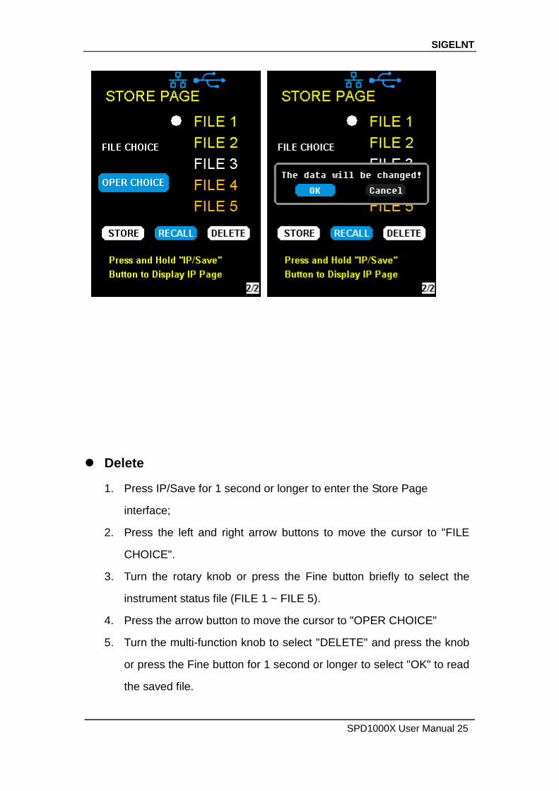
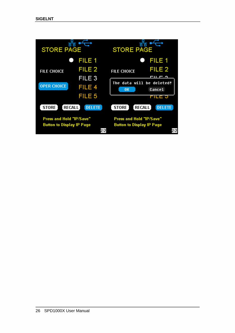
Delete
1. Press IP/Save for 1 second or longer to enter the Store Page
interface;
2. Press the left and right arrow buttons to move the cursor to "FILE
CHOICE".
3. Turn the rotary knob or press the Fine button briefly to select the
instrument status file (FILE 1 ~ FILE 5).
4. Press the arrow button to move the cursor to "OPER CHOICE"
5. Turn the multi-function knob to select "DELETE" and press the knob
or press the Fine button for 1 second or longer to select "OK" to read
the saved file.
SIGELNT
26 SPD1000X User Manual

SIGELNT
SPD1000X User Manual 27
2.6 Timer
The SPD1000X provides a timer function. The timer can save five sets of
settings, each set independent of the others. The user can set arbitrary
parameters within the voltage, current, and dwell time values. The timer
supports continuous output, with the longest time-out time of up to 10000 s.
Set the timer parameter
Method 1:
1. Press Timer/Wave to enter the Timer Setup interface, and the
indicator will illuminate.
2. Pressing the arrow keys, move the cursor to select the desired
parameter (voltage/current/time).
3. Rotate the multi-function knob or press the left and right buttons for 1
second or longer period to set the corresponding value. The Fine
button can be used to move between the digits in any highlighted field.
4. Press Timer/Wave again to exit the Timer interface.
SIGELNT
28 SPD1000X User Manual
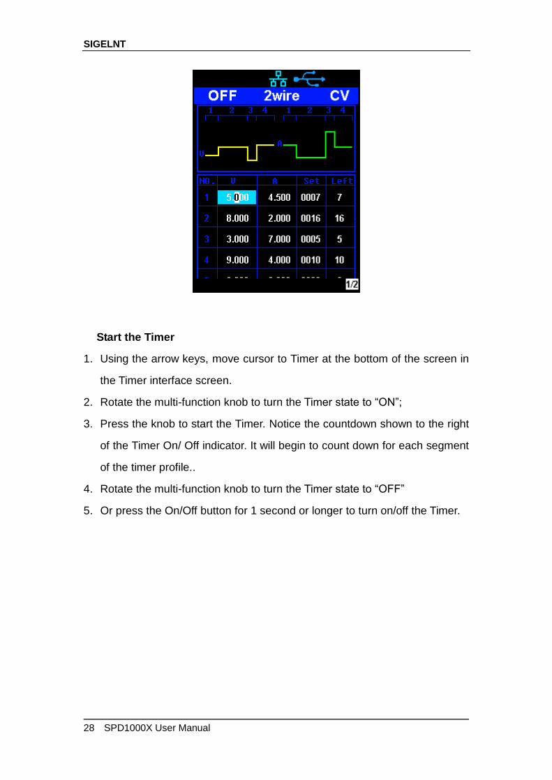
Start the Timer
1. Using the arrow keys, move cursor to Timer at the bottom of the screen in
the Timer interface screen.
2. Rotate the multi-function knob to turn the Timer state to “ON”;
3. Press the knob to start the Timer. Notice the countdown shown to the right
of the Timer On/ Off indicator. It will begin to count down for each segment
of the timer profile..
4. Rotate the multi-function knob to turn the Timer state to “OFF”
5. Or press the On/Off button for 1 second or longer to turn on/off the Timer.
SIGELNT
SPD1000X User Manual 29
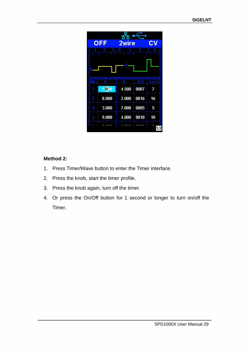
Method 2:
1. Press Timer/Wave button to enter the Timer interface.
2. Press the knob, start the timer profile.
3. Press the knob again, turn off the timer.
4. Or press the On/Off button for 1 second or longer to turn on/off the
Timer.
SIGELNT
30 SPD1000X User Manual
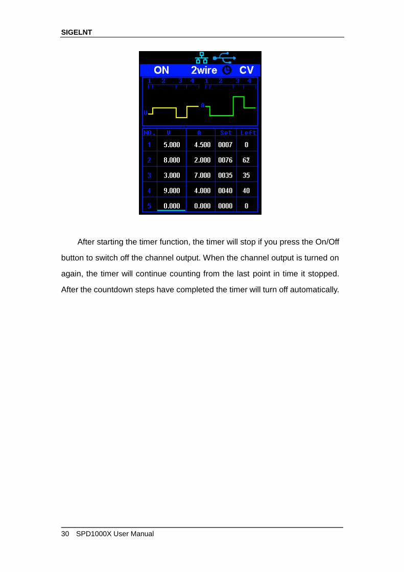
After starting the timer function, the timer will stop if you press the On/Off
button to switch off the channel output. When the channel output is turned on
again, the timer will continue counting from the last point in time it stopped.
After the countdown steps have completed the timer will turn off automatically.
SIGELNT
SPD1000X User Manual 31
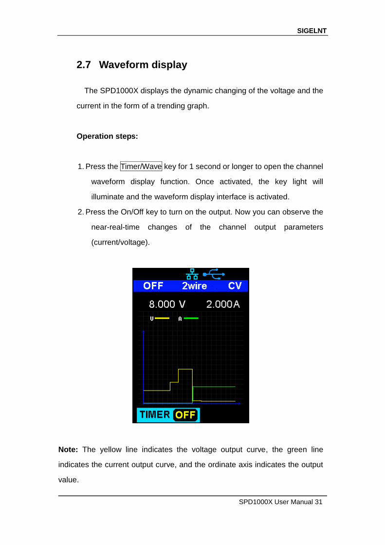
2.7 Waveform display
The SPD1000X displays the dynamic changing of the voltage and the
current in the form of a trending graph.
Operation steps:
1. Press the Timer/Wave key for 1 second or longer to open the channel
waveform display function. Once activated, the key light will
illuminate and the waveform display interface is activated.
2. Press the On/Off key to turn on the output. Now you can observe the
near-real-time changes of the channel output parameters
(current/voltage).
Note: The yellow line indicates the voltage output curve, the green line
indicates the current output curve, and the ordinate axis indicates the output
value.
SIGELNT
32 SPD1000X User Manual
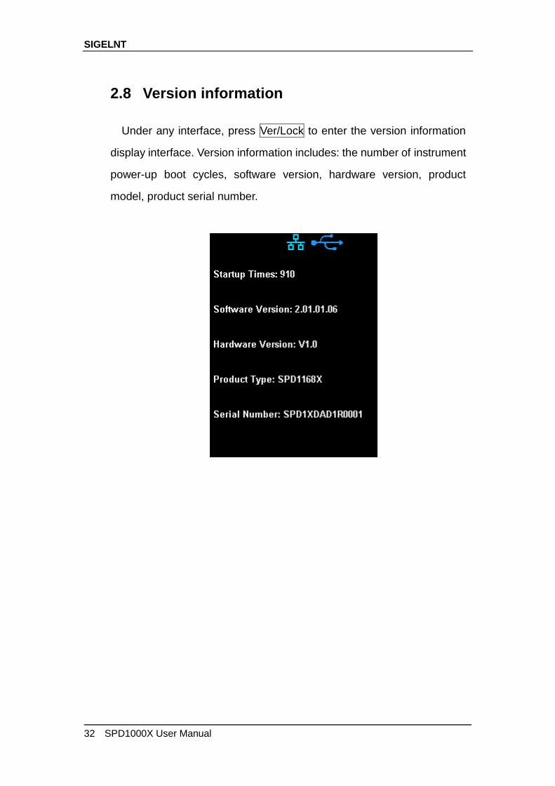
2.8 Version information
Under any interface, press Ver/Lock to enter the version information
display interface. Version information includes: the number of instrument
power-up boot cycles, software version, hardware version, product
model, product serial number.
SIGELNT
SPD1000X User Manual 33
2.9 Lock key
The SPD1000X allows the user to lock the front panel keys to avoid
the risk of inadvertently changing a setting. Under any interface on the
front panel, press the Ver/Lock key for 1 second or longer to enable the
key lock function. At this point, the other buttons on the front panel are
disabled, except for the power button. After the lock function is enabled,
a "lock" icon appears at the top of the screen. Press and hold the
Ver/Lock key again to disable the key lock function. The "Lock" icon at
the top of the screen disappears.
SIGELNT
34 SPD1000X User Manual
2.10 Upgrade firmware
Software Upgrades are performed using Easypower, a PC-based
management software program (available on the Siglent website), this is
used to update the power supplies firmware via USB Device or LAN.
Upgrade as follows:
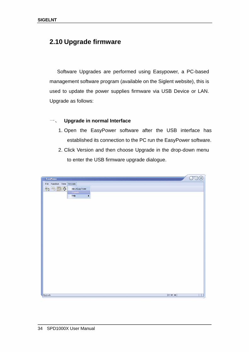
一、 Upgrade in normal Interface
1. Open the EasyPower software after the USB interface has
established its connection to the PC run the EasyPower software.
2. Click Version and then choose Upgrade in the drop-down menu
to enter the USB firmware upgrade dialogue.
SIGELNT
SPD1000X User Manual 35
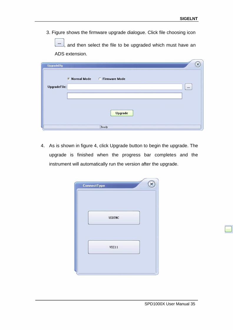
3. Figure shows the firmware upgrade dialogue. Click file choosing icon
, and then select the file to be upgraded which must have an
ADS extension.
4. As is shown in figure 4, click Upgrade button to begin the upgrade. The
upgrade is finished when the progress bar completes and the
instrument will automatically run the version after the upgrade.
SIGELNT
36 SPD1000X User Manual
二、 Upgrade Via Guide Procedure
Upgrade via guide procedure also can be used if the method above
does not work. Specific steps are as follows:
1. Press the knob and simultaneously turn on the instrument. It will now
enter the guide procedure mode.
2. After entering the guide procedure mode, the upgrade method is the
same as in the previous procedure.
SIGELNT
SPD1000X User Manual 37
Chapter 3 Remote control
3.1 Control method
Based on NI-VISA
Users can remotely control the instrument by using NI-VISA from NI
(National Instruments Corporation). In regards to NI-VISA, there is a full
version and a live version (Run-Time Engine version). The full version
includes NI device drivers and a tool called NI MAX. NI MAX is a user
interface that controls the device. The real-time version is much smaller
than the full version and includes only NI device drivers.
For example, you can download and install the full version of NI-VISA
5.4 at http://www.ni.com/download/ni-visa-5.4/4230/en/.
Next use the USB cable to connect the SPD1000X (via the rear
panel's USB Device connector) to the computer or use a network cable
to connect the SPD1000X (through the back-panel’s LAN connector) to
the computer's LAN.
Based on NI-VISA, the user can remotely control the SPD1000X in
two ways; one through the PC software EasyPower and the other
through custom programming with SCPI commands. For more
information, see Programming Examples.
Using Socket
Users can also use Socket through the network port and SPD1000X
for TCP/IP protocol-based communications. Socket communication is a
SIGELNT
38 SPD1000X User Manual
basic communication technology in computer networks. It allows
applications to communicate through network hardware and the
standard network protocol built into the operating system. This method
requires two-way communication between the instrument and the
computer network through an IP address and a fixed port number.
SPD1000X Socket communication port is 5025.
Using a network cable after connecting the SPD1000X (through the
rear panel LAN connector) to the local area network where the computer
is located, you can customize the programming with SCPI commands to
remotely control the SPD1000X. For more information, see
Programming Examples.
3.2 Grammar conventions
The SCPI command is a tree hierarchy that includes multiple
subsystems, each consisting of a root key and one or more level keys.
Command keywords are separated by a colon ":". The keywords are
followed by optional parameter settings. Commands and parameters are
separated by a space, and the parameters are separated by commas ",",
add a question mark "?", after the command line to inquire about this
function.
Most SCPI commands are a mixture of uppercase and lowercase
letters. Capital letters indicate abbreviations of shortened commands. For
better program readability, use the long commands convention. For
example,
[CH1:]VOLTage <voltage>
VOLT or VOLTage, uppercase and lowercase letters in any
combination will work. Therefore, VolTaGe, volt and Volt are acceptable.
Other formats such as VOL and VOLTAG will generate errors.
SIGELNT
SPD1000X User Manual 39
Brackets ({}) contain parameter choices. Brackets are not sent with the
command string.
Vertical line (|) separates parameter selections.
Angle brackets (<>) indicates that you must specify a value for the
parameter inside the brackets. For example, for the <voltage> parameter
in angle brackets for the above command, you must specify a value for
this parameter (for example, "CH1: VOLT 10"). Angle brackets do not
send angle brackets along with the command string.
Optional parameters are enclosed in square brackets ([]). If you do not
specify a value for the optional parameter, the instrument uses the default
value. For example, [CH1:] in the above command can be omitted (for
example, "VOLT 10"). At this time, the command will operate on the
current channel. Brackets are not sent with the command string.
3.3 Command Summary
1、 *IDN?
2、 *SAV
3、 *RCL
4、 INSTrument {CH1|CH2}
5、 INSTrument ?
6、 MEASure:CURRent?
7、 MEAsure:VOLTage?
8、 MEASure:POWEr?
9、 [SOURce:]CURRent <current>
SIGELNT
40 SPD1000X User Manual
10、 [SOURce:]CURRent ?
11、 [SOURce:]VOLTage <volt>
12、 [SOURce:] VOLTage?
13、 OUTPut
14、 OUTPut:TRACk
15、 OUTPut:WAVE
16、 TIMEr:SET
17、 TIMEr:SET?
18、 TIMEr
19、 SYSTem:ERRor?
20、 SYSTem:VERSion?
21、 SYSTem: STATus?
SIGELNT
SPD1000X User Manual 41
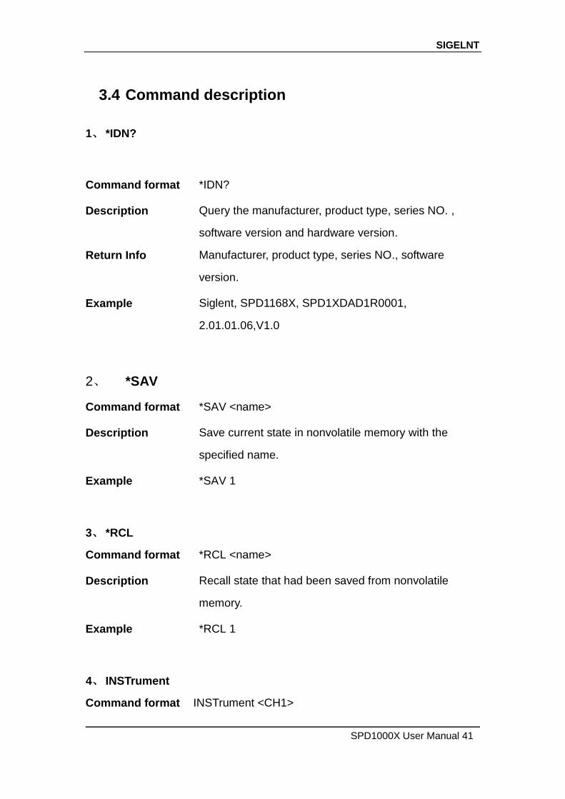
3.4 Command description
1、 *IDN?
Command format *IDN?
Description Query the manufacturer, product type, series NO. ,
software version and hardware version.
Return Info Manufacturer, product type, series NO., software
version.
Example Siglent, SPD1168X, SPD1XDAD1R0001,
2.01.01.06,V1.0
2、 *SAV
Command format *SAV <name>
Description Save current state in nonvolatile memory with the
specified name.
Example *SAV 1
3、 *RCL
Command format *RCL <name>
Description Recall state that had been saved from nonvolatile
memory.
Example *RCL 1
4、 INSTrument
Command format INSTrument <CH1>
SIGELNT
42 SPD1000X User Manual
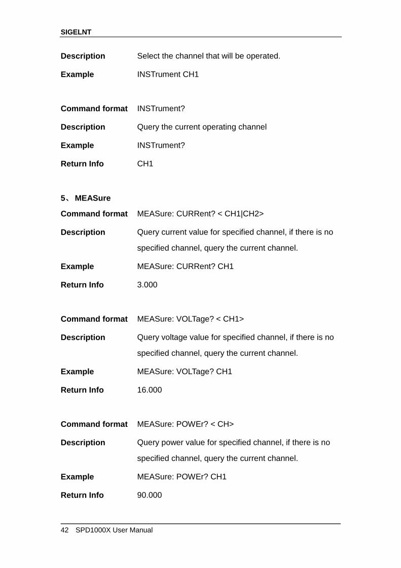
Description Select the channel that will be operated.
Example INSTrument CH1
Command format INSTrument?
Description Query the current operating channel
Example INSTrument?
Return Info CH1
5、 MEASure
Command format MEASure: CURRent? < CH1|CH2>
Description Query current value for specified channel, if there is no
specified channel, query the current channel.
Example MEASure: CURRent? CH1
Return Info 3.000
Command format MEASure: VOLTage? < CH1>
Description Query voltage value for specified channel, if there is no
specified channel, query the current channel.
Example MEASure: VOLTage? CH1
Return Info 16.000
Command format MEASure: POWEr? < CH>
Description Query power value for specified channel, if there is no
specified channel, query the current channel.
Example MEASure: POWEr? CH1
Return Info 90.000

SIGELNT
SPD1000X User Manual 43
6、 CURRent
Command format <SOURce:>CURRent <value>
<SOURce>:={CH1}
Description Set current value of the selected channel
Example CH1:CURRent 0.5
Command format <SOURce>: CURRent?
<SOURce>:={CH1}
Description Query the current value of the selected channel.
Example CH1: CURRent?
Return Info 0.500
7、 VOLTage
Command format <SOURce>: VOLTage <value>
<SOURce>:={CH1}
Description Set voltage value of the selected channel
Example CH1: VOLTage 15
Command format <SOURce>:CURRent?
<SOURce>:={CH1}
Description Query the voltage value of the selected channel.
Example CH1: VOLTage?
Return Info 15.000
SIGELNT
44 SPD1000X User Manual
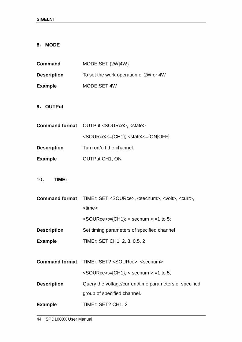
8、 MODE
Command MODE:SET {2W|4W}
Description To set the work operation of 2W or 4W
Example MODE:SET 4W
9、 OUTPut
Command format OUTPut <SOURce>, <state>
<SOURce>:={CH1}; <state>:={ON|OFF}
Description Turn on/off the channel.
Example OUTPut CH1, ON
10、 TIMEr
Command format TIMEr: SET <SOURce>, <secnum>, <volt>, <curr>,
<time>
<SOURce>:={CH1}; < secnum >;=1 to 5;
Description Set timing parameters of specified channel
Example TIMEr: SET CH1, 2, 3, 0.5, 2
Command format TIMEr: SET? <SOURce>, <secnum>
<SOURce>:={CH1}; < secnum >;=1 to 5;
Description Query the voltage/current/time parameters of specified
group of specified channel.
Example TIMEr: SET? CH1, 2

SIGELNT
SPD1000X User Manual 45
Return Info 3, 0.5, 2
Command format TIMEr <SOURce>, <state>
<SOURce>:={CH1}; < state >;={ON | OFF};
Description Turn on/off Timer function of specified channel
Instruction The command works effectively only when <secnum>
starts from 1.
Example TIMEr CH1, ON
11、 SYSTem
Command format SYSTem: ERRor?
Description Query the error code and the information of the
equipment.
Command format SYSTem: VERSion?
Description Query the software version of the equipment.
Example SYSTem: VERSion?
Return Info 2.01.01.06
Command format SYSTem: STATus?
Description Query the current working state of the equipment.
Instruction The return info is Hexadecimal format, but the actual
state is binary, so you must change the return info into a
binary format. The state correspondence relationship is

SIGELNT
46 SPD1000X User Manual
as follows.
Example SYSTem: STATus?
Return info 0x0224
Explanation: The returned information is hexadecimal, so the user needs to
convert to binary format when confirming the status. See the following table:
Bit NO. Corresponding state
0 0: CV mode 1: CC mode
4 0: Output OFF 1: Output ON
5 0: 2W mode 1: 4W mode
6 0: TIMER OFF 1: TIMER ON
8 0: digital display; 1: waveform display
12、 IPaddr
Command format IPaddr <IP address>
Description Used to assign a Static Internet Protocol (IP) address to
the instrument
Example
Explanation
IPaddr 10.11.13.214
This command is invalid when the power is currently set
to automatically obtain the network configuration (DHCP
is ON)
Command format IPaddr?
Description Query the software the setting of IP address
Example SYSTem: VERSion?
SIGELNT
SPD1000X User Manual 47
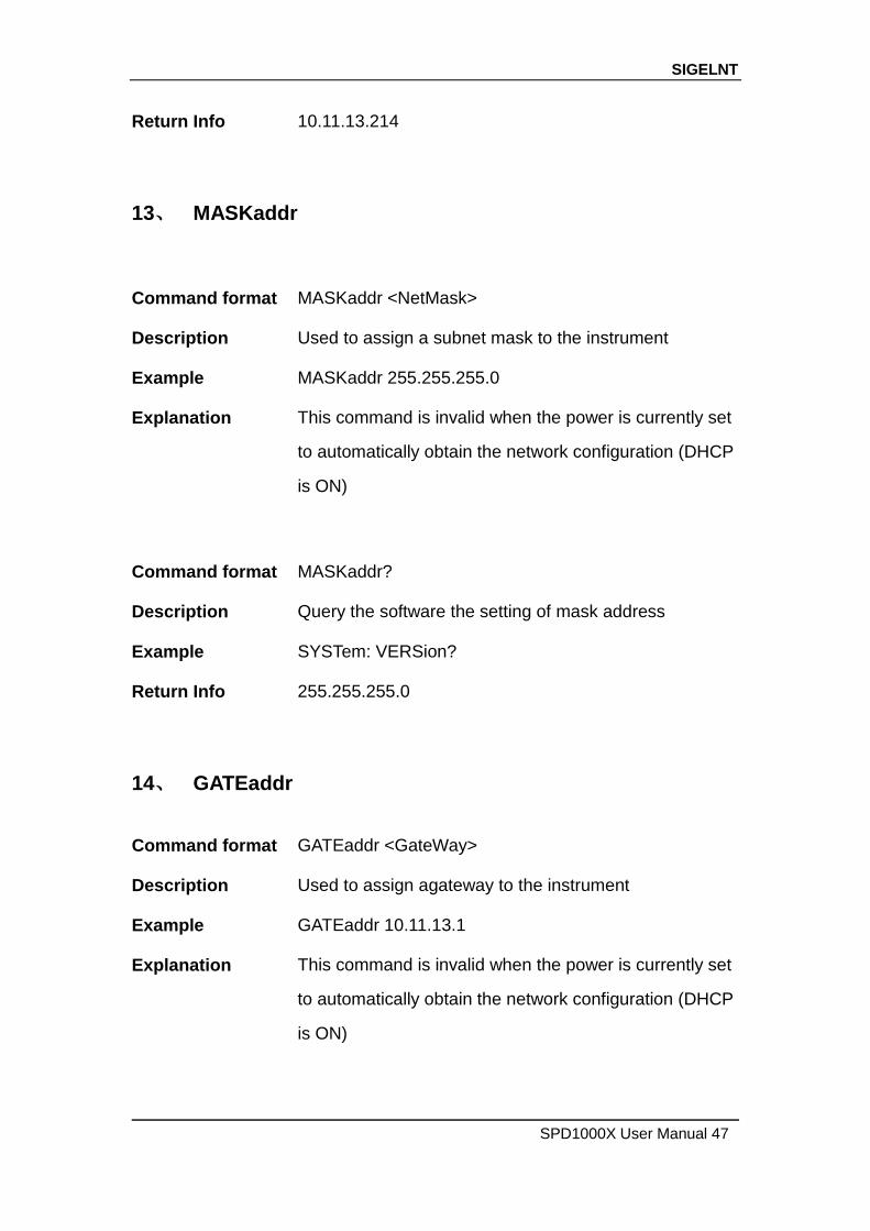
Return Info 10.11.13.214
13、 MASKaddr
Command format MASKaddr <NetMask>
Description Used to assign a subnet mask to the instrument
Example
Explanation
MASKaddr 255.255.255.0
This command is invalid when the power is currently set
to automatically obtain the network configuration (DHCP
is ON)
Command format MASKaddr?
Description Query the software the setting of mask address
Example SYSTem: VERSion?
Return Info 255.255.255.0
14、 GATEaddr
Command format GATEaddr <GateWay>
Description Used to assign agateway to the instrument
Example
Explanation
GATEaddr 10.11.13.1
This command is invalid when the power is currently set
to automatically obtain the network configuration (DHCP
is ON)
SIGELNT
48 SPD1000X User Manual
Command format MASKaddr?
Description Query the software the setting of gateway address
Return Info 10.11.13.1
15、 DHCP
Command format DHCP{ON|OFF}
Description Turn on or off the instrument's automatic network
configuration feature.
Example
DHCP ON
Command format DHCP?
Description This is used to query whether the current automatic
network configuration of the instrument is enabled
Return Info ON
16、 *LOCK
Command format *LOCK
Description Turn on the key lock to disable local or remote settings.
Example
*LOCK
Command format *UNLOCK
Description Turn off the key lock to validate the setting
Example *UNLOCK
SIGELNT
SPD1000X User Manual 49
3.5 Programming examples
This section lists examples of programming with SCPI commands
based on NI-VISA or Socket in Visual C ++, Visual Basic, MATLAB,
Python, and more.
NI-VISA-based programming examples
1. First confirm that your computer has installed the NI VISA library (NI
website can be downloaded from http://www.ni.com). The default
installation path in this article is C: \Program Files\IVI
Foundation\VISA.
2. This article mainly uses the power of the USB interface and PC
communications, some examples involve the use of LAN interface.
Please use the USB cable to connect the USB Device port on the
rear panel of the power supply to the USB port on the PC. You can
also use the LAN interface to communicate with the PC.
3. After the power is correctly connected to the PC for the first time,
power on the instrument. At this time, the Hardware Update Wizard
dialog box will pop up. Follow the instructions of the wizard to install
the "USB Test and Measurement Device".
At this point, programming preparation is completed. The following
will detail the Visual C + +, Visual Basic and MATLAB development
environment programming examples.
Visual C ++ programming examples
Environment: Win7 32bit system, Visual Studio
Example content: Using NI-VISA, access control devices via

SIGELNT
50 SPD1000X User Manual
USBTMC and TCP/IP, send commands to read the return value.
Follow these steps to complete the example:
1、 Open Visual Studio and create a new vc ++ win32 project.
Setting up the project environment to use the ni-visa library, you
have two options for using ni-visa, static mode and automatic mode:
(1) static mode:
Find the files on the NI-VISA installation path: visa.h, visatype.h,
visa32.lib. Copy them to your project and add them to the project. In
the project .cpp file, add the following two lines
#include "visa.h"
#pragma comment(lib,"visa32.lib")
(2) automatic mode
Set .h files include directory, ni-visa installation path. In our
computer, we set the path to: C: \Program Files\IVI
Foundation\VISA\WINNT\include. Set this path to the project -
Properties ——C / C ++ —— General - Additional include path, as
shown:
Set the library path to set the library file:
Set the library path: In your ni-visa installation path, in our computer,
we set the path is: C: \Program Files\IVI Foundation\VISA\WINNT\LIB

SIGELNT
SPD1000X User Manual 51
\MSC. Set this path to Project - Performance - Connector - General -
additional library directory, as shown:
Set the library file:project---properties---Linker---Command
Line---Additional Options:visa32.lib
Including visa.h file: in XXX.cpp file:
#include <visa.h>
2、 Add code
(1) Based on USB interface code :
Write a Usbtmc_test function.
int Usbtmc_test ()
{
/* This code demonstrates using NI-VISA to send synchronous read
and write commands to a USB Test & Measurement Class (USBTMC)
instrument */
/* This example writes "* IDN? \n" string to all USBTMCs devices
SIGELNT
52 SPD1000X User Manual
connected to the system and tries to read back the result using a
read-write function */
/* The general flow of the code is to open the Explorer */
/* Open the VISA session to the instrument */
/* Use viPrintf to write the instrument flag */
/* Try to read a response with viScanf */
/* Close the VISA session */
/***********************************************************/
ViSession defaultRM;
ViSession instr;
ViUInt32 numInstrs;
ViFindList findList;
ViStatus status;
char instrResourceString[VI_FIND_BUFLEN];
unsigned char buffer[100];
char stringinput[512];
int i;
/* First, we have to call viOpenDefaultRM to get the manager's
handle */
/* We will store this handle in defaultRM */
}
status=viOpenDefaultRM (&defaultRM);
if (status < VI_SUCCESS)
{
printf ("Could not open a session to the VISA Resource
Manager!\n");
return status;
}
SIGELNT
SPD1000X User Manual 53
/** Look for all USB TMC VISA resources in our system */
/* Then the number of resources stored in the system numInstrs
Lane*/
status = viFindRsrc (defaultRM, "USB?*INSTR", &findList,
&numInstrs, instrResourceString);
if (status < VI_SUCCESS)
{
printf ("An error occurred while finding resources.\nHit enter to
continue.");
fflush(stdin);
getchar();
viClose (defaultRM);
return status;
}
We will now open a VISA session for all USB TMC instruments. We have to
use a handle from viOpenDefaultRM, and we have to use a string to indicate
the instrument to open, which is called instrument descriptor. The format of the
string can be found in the right-click parameter description in the function panel.
After opening a session to the device, we get a handle to the instrument used
later when using the VISA feature. The AccessMode and timeout parameters
in this function are reserved for future functions. These two parameters are
given the value VI_NULL. */
for (i=0; i<int(numInstrs); i++)
{
if (i > 0)
viFindNext (findList, instrResourceString);
status = viOpen (defaultRM, instrResourceString, VI_NULL, VI_NULL, &instr);
if (status < VI_SUCCESS)
{
printf ("Cannot open a session to the device %d.\n", i+1);
continue;
}
/** At this point, we now have a session open to the USB TMC instrument. Now, we
will use the viPrintf function to send the string "* IDN? \ N" to the device, asking the
device to recognize */
SIGELNT
54 SPD1000X User Manual
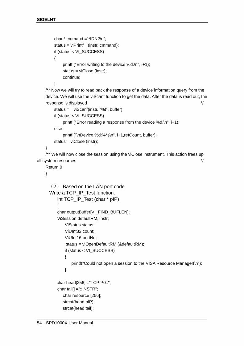
char * cmmand ="*IDN?\n";
status = viPrintf (instr, cmmand);
if (status < VI_SUCCESS)
{
printf ("Error writing to the device %d.\n", i+1);
status = viClose (instr);
continue;
}
/** Now we will try to read back the response of a device information query from the
device. We will use the viScanf function to get the data. After the data is read out, the
response is displayed */
status = viScanf(instr, "%t", buffer);
if (status < VI_SUCCESS)
printf ("Error reading a response from the device %d.\n", i+1);
else
printf ("\nDevice %d:%*s\n", i+1,retCount, buffer);
status = viClose (instr);
}
/** We will now close the session using the viClose instrument. This action frees up
all system resources */
Return 0
}
(2) Based on the LAN port code
Write a TCP_IP_Test function.
int TCP_IP_Test (char * pIP)
{
char outputBuffer[VI_FIND_BUFLEN];
ViSession defaultRM, instr;
ViStatus status;
ViUInt32 count;
ViUInt16 portNo;
status = viOpenDefaultRM (&defaultRM);
if (status < VI_SUCCESS)
{
printf("Could not open a session to the VISA Resource Manager!\n");
}
char head[256] ="TCPIP0::";
char tail[] ="::INSTR";
char resource [256];
strcat(head,pIP);
strcat(head,tail);
SIGELNT
SPD1000X User Manual 55
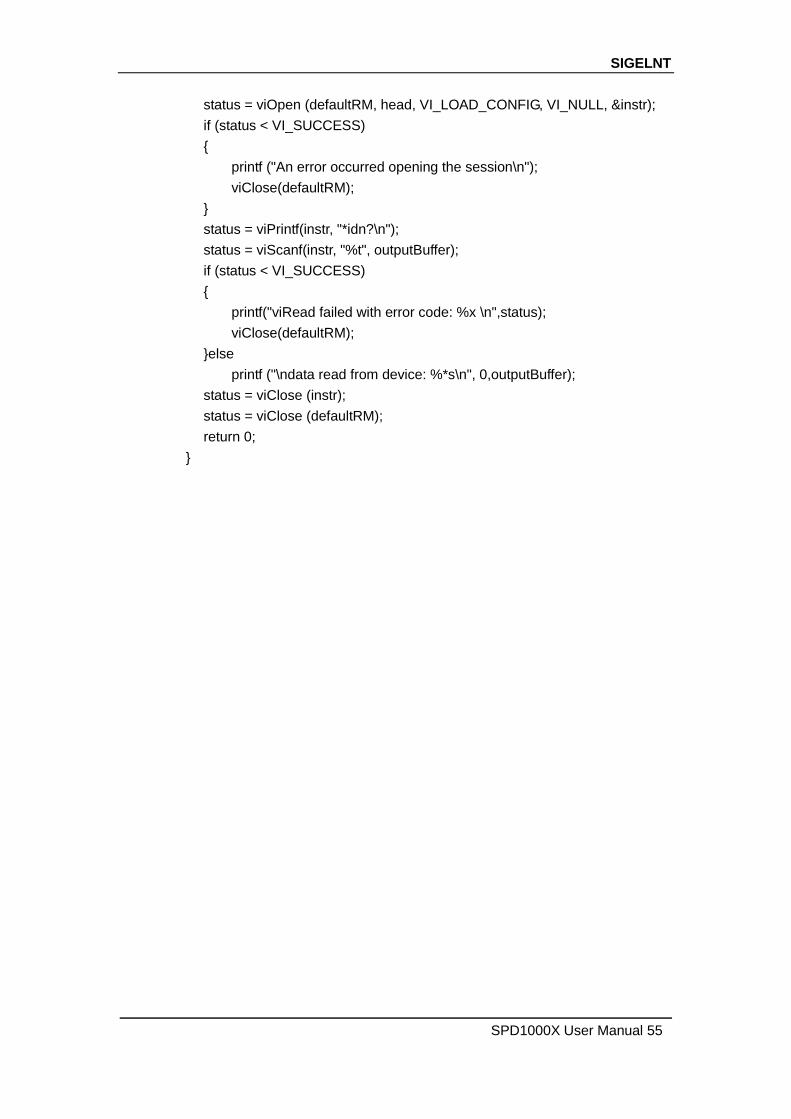
status = viOpen (defaultRM, head, VI_LOAD_CONFIG, VI_NULL, &instr);
if (status < VI_SUCCESS)
{
printf ("An error occurred opening the session\n");
viClose(defaultRM);
}
status = viPrintf(instr, "*idn?\n");
status = viScanf(instr, "%t", outputBuffer);
if (status < VI_SUCCESS)
{
printf("viRead failed with error code: %x \n",status);
viClose(defaultRM);
}else
printf ("\ndata read from device: %*s\n", 0,outputBuffer);
status = viClose (instr);
status = viClose (defaultRM);
return 0;
}
SIGELNT
56 SPD1000X User Manual
Visual Basic programming examples
Environment: Windows 7 32-bit systerm , Microsoft Visual Basic 6.0
Example Content: Using NI-VISA, access control devices via USBTMC and
TCP/IP, send commands to read the return value.
Follow the steps to complete the example:
1 Open Visual Basic, create a standard application project (Standard EXE).
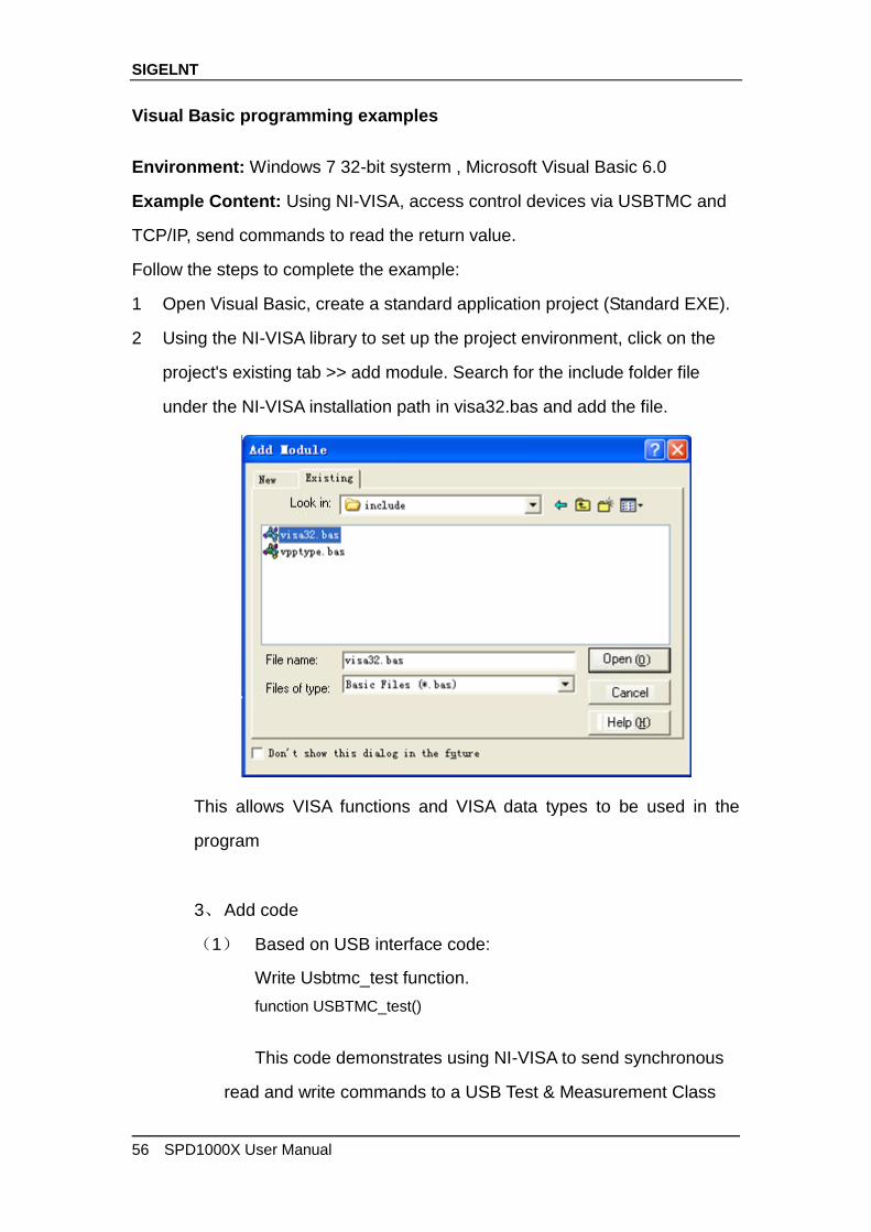
2 Using the NI-VISA library to set up the project environment, click on the
project's existing tab >> add module. Search for the include folder file
under the NI-VISA installation path in visa32.bas and add the file.
This allows VISA functions and VISA data types to be used in the
program
3、 Add code
(1) Based on USB interface code:
Write Usbtmc_test function.
function USBTMC_test()
This code demonstrates using NI-VISA to send synchronous
read and write commands to a USB Test & Measurement Class
SIGELNT
SPD1000X User Manual 57
(USBTMC) instrument.
Create a VISA-USB object to connect to the USB instrument
vu = visa ('ni', 'USB0 :: 0xF4EC :: 0x1300 :: 0123456789 :: INSTR');
fopen(vu);
fprintf(vu,'*IDN?');
outputbuffer = fscanf(vu);
disp(outputbuffer);
fclose(vu);
delete(vu);
clear vu;
end
(2) Based on the LAN port code:
Write to the TCP_IP_Test function.
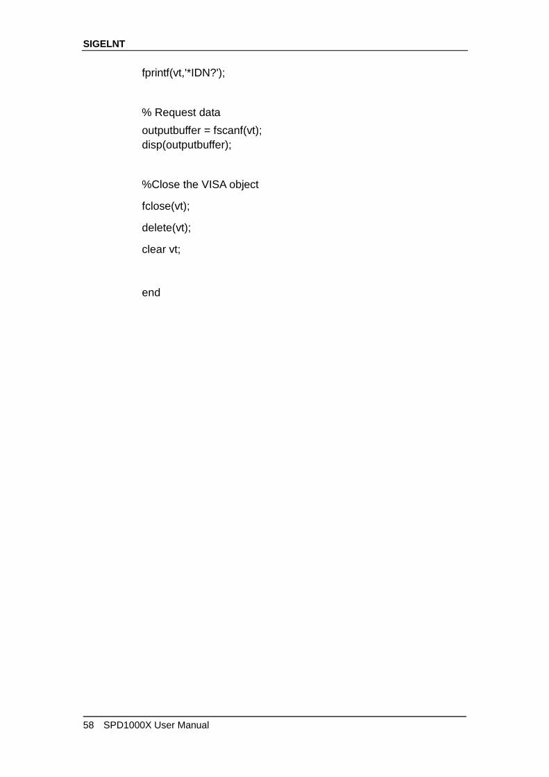
function TCP_IP_test( IPstr )
% This code demonstrates using NI-VISA to send synchronous
read and write commands to a TCP / IP instrument.
% Create a VISA-TCPIP object to connect to an instrument with
an IP address configured
vt = visa('ni',['TCPIP0::',IPstr,'::INSTR']);
% Open the created VISA object
fopen(vt);
% Send the string "* IDN?" To query device information
SIGELNT
58 SPD1000X User Manual
fprintf(vt,'*IDN?');
% Request data
outputbuffer = fscanf(vt);
disp(outputbuffer);
%Close the VISA object
fclose(vt);
delete(vt);
clear vt;
end
SIGELNT
SPD1000X User Manual 59
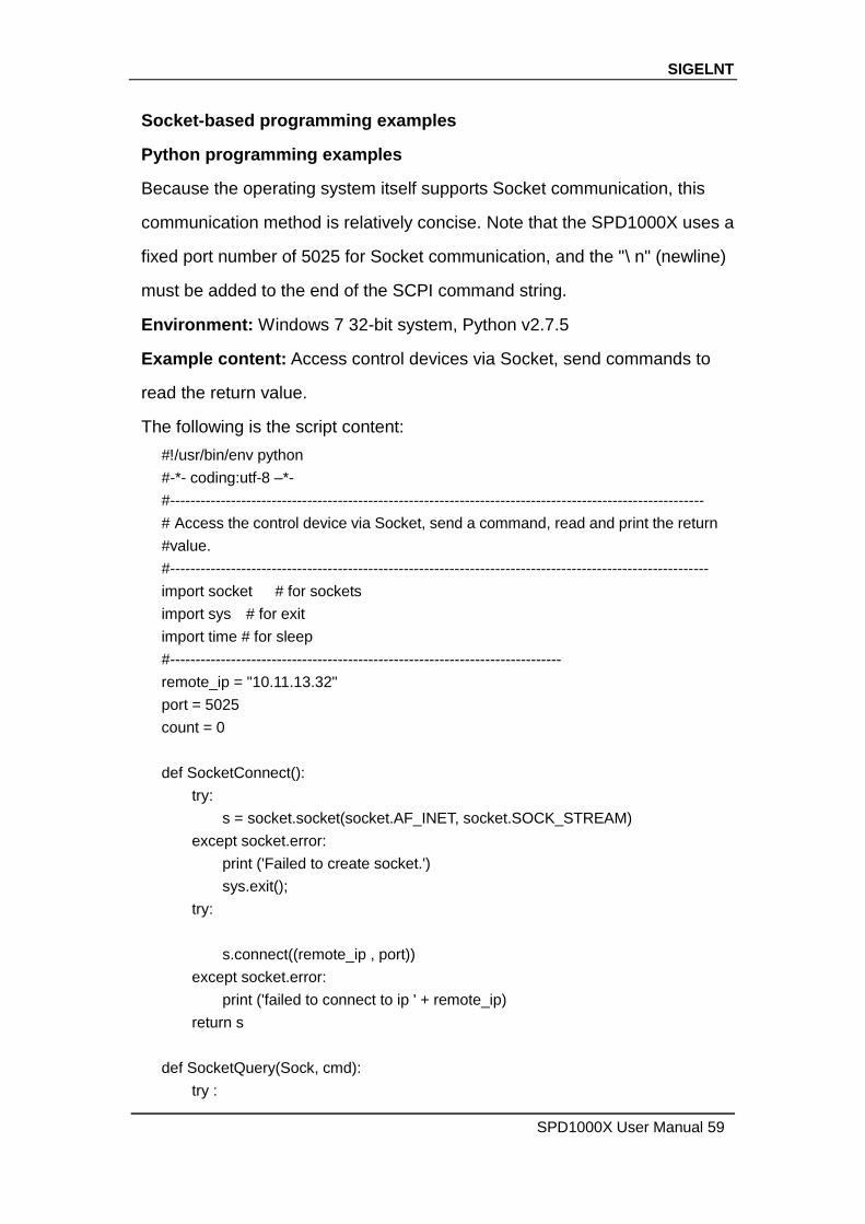
Socket-based programming examples
Python programming examples
Because the operating system itself supports Socket communication, this
communication method is relatively concise. Note that the SPD1000X uses a
fixed port number of 5025 for Socket communication, and the "\ n" (newline)
must be added to the end of the SCPI command string.
Environment: Windows 7 32-bit system, Python v2.7.5
Example content: Access control devices via Socket, send commands to
read the return value.
The following is the script content:
#!/usr/bin/env python
#-*- coding:utf-8 –*-
#---------------------------------------------------------------------------------------------------------
# Access the control device via Socket, send a command, read and print the return
#value.
#----------------------------------------------------------------------------------------------------------
import socket # for sockets
import sys # for exit
import time # for sleep
#-----------------------------------------------------------------------------
remote_ip = "10.11.13.32"
port = 5025
count = 0
def SocketConnect():
try:
s = socket.socket(socket.AF_INET, socket.SOCK_STREAM)
except socket.error:
print ('Failed to create socket.')
sys.exit();
try:
s.connect((remote_ip , port))
except socket.error:
print ('failed to connect to ip ' + remote_ip)
return s
def SocketQuery(Sock, cmd):
try :

SIGELNT
60 SPD1000X User Manual
Sock.sendall(cmd)
time.sleep(1)
except socket.error:
print ('Send failed')
sys.exit()
reply = Sock.recv(4096)
return reply
def SocketClose(Sock):
Sock.close()
time.sleep(.300)
def main():
global remote_ip
global port
global count
s = SocketConnect()
for i in range(10):
qStr = SocketQuery(s, b'*IDN?\n')
print (str(count) + ":: " + str(qStr))
count = count + 1
SocketClose(s)
input('Press "Enter" to exit')
if __name__ == '__main__':
proc = main()
SIGELNT
SPD1000X User Manual 61
Chapter 4 Common troubleshooting
The most commonly encountered failures and their solutions are listed
below. Please use these steps listed if an error occurs. If the problem
persists, please contact SIGLENT .
1. The instrument will not power on.
(1) Check whether the power is correctly connected.
(2) Check whether the power switch at the front panel is on.
(3) Remove the power cord and check whether the voltage selector is at
the proper setting, whether the specification of the fuse is correct and
whether the fuse is intact. If the fuse needs to be changed, refer to “To
Replace the Fuse”.
(4) If the problem remains, please contact SIGLENT.
2. The constant voltage output is abnormal.
(1) Check whether the maximum output power of the scale currently
selected fulfills the load requirement. If yes, go to the next step.
(2) Check whether the cable connecting the load and power supply is
short-circuited and is making good contact.
(3) Check whether the load is normal.
(4) Check whether the current setting value of this scale is proper; if it is
too low, increase it accordingly
(5) If the problem remains, please contact SIGLENT.
SIGELNT
62 SPD1000X User Manual
3. The constant current output is abnormal.
(1) Check whether the maximum output power of the scale currently
selected fulfills the load requirement. If yes, go to the next step.
(2) Check whether the cable connecting the load and power supply is
short-circuited and is making good contact.
(3) Check whether the load is normal.
(4) Check whether the voltage setting value of this scale is proper; if it is
too low, increase it properly.
(5) If the problem persists, please contact SIGLENT.

SIGELNT
SPD1000X User Manual 63
Chapter 5 Service and Support
5.1 Maintenance summary
SIGLENT warrants that the products that it manufactures and sells
will be free from defects in materials and workmanship for a period of
three years from the date of shipment from an authorized SIGLENT
distributor. If a product or CRT proves defective within the respective
period, SIGLENT will provide repair or replacement as described in the
complete warranty statement.
To arrange for service or obtain a copy of the complete warranty
statement, please contact your nearest SIGLENT sales and service office.
Except as provided in this summary or the applicable warranty Statement,
SIGLENT makes no warranty of any kind, express or implied, including
without limitation the implied warranties of merchantability and fitness for
a particular purpose. In no Event shall SIGLENT be liable for indirect,
special or Consequential damages
5.2 Contact SIGLENT
SIGLENT TECHNOLOGIES CO.,LTD
Address: 3/F, Building 4, Antongda Industrial Zone, 3rd Liuxian Road, 68
District, Bao’an District, Shenzhen, P.R. CHINA.
Tel: +86-755-36615186
E-mail:[email protected]
http://www.siglent.com

SIGELNT
64 SPD1000X User Manual
America
SIGLENT Technologies America, Inc
6557 Cochran Rd Solon, Ohio 44139
Tel: 440-398-5800
Toll Free:877-515-5551
Fax: 440-399-1211
www.siglentamerica.com
Headquarters
SIGLENT TECHNOLOGIES CO., LTD.
Blog No.4 & No.5, Antongda Industrial Zone, 3rd Liuxian Road, Bao’an
District, Shenzhen, 518101, China.
Tel:+ 86 755 3688 7876
Fax:+ 86 755 3359 1582
www.siglent.com/ens
Europe
SIGLENT TECHNOLOGIES EUROPE GmbH
Liebigstrasse 2-20, Gebaeude 14, 22113 Hamburg Germany
Tel: +49(0)40-819-95946
Fax: +49(0)40-819-95947
www.siglenteu.com