user manual interroll rollerdrive...aluminum or stainless steel (with or without sleeves) roller...
TRANSCRIPT
User manual
Interroll RollerDriveEC100
EC110Chapter-ID: User manualChapter-ID: VersionChapter-ID: Translation of the original instructions
Version 3.0 (04/2013) en
Translation of the original
instructions

Manufacturer's addressInterroll Engineering GmbH Hoeferhof 16D-42929 WermelskirchenTel. +49 2193 23 0Fax. +49 2190 2022www.interroll.com
CopyrightThe copyright of this manual remains with Interroll Engineering GmbH. The operating instructions contain technical regulations and drawings which may not be reproduced partially or in full, transmitted by any means, utilized without permission for competitive purposes or disclosed to third parties.
Version 3.0 (04/2013) en
Translation of the original instructions

RollerDrive EC100 / EC110
Table of contentsIntroduction
Information about the operating instructions . . . . . . . . . . . . . . . . . . . . . . . . 2Warnings in this manual . . . . . . . . . . . . . . . . . . . . . . . . . . . . . . . . . . . . . . . 2Further symbols . . . . . . . . . . . . . . . . . . . . . . . . . . . . . . . . . . . . . . . . . . . . . 3
SafetyGeneral safety instructions. . . . . . . . . . . . . . . . . . . . . . . . . . . . . . . . . . . . . 4Intended use . . . . . . . . . . . . . . . . . . . . . . . . . . . . . . . . . . . . . . . . . . . . . . . 4Unintended use . . . . . . . . . . . . . . . . . . . . . . . . . . . . . . . . . . . . . . . . . . . . . 4Qualified persons . . . . . . . . . . . . . . . . . . . . . . . . . . . . . . . . . . . . . . . . . . . . 5Dangers . . . . . . . . . . . . . . . . . . . . . . . . . . . . . . . . . . . . . . . . . . . . . . . . . . . 5Interfaces . . . . . . . . . . . . . . . . . . . . . . . . . . . . . . . . . . . . . . . . . . . . . . . . . . 6Operating modes . . . . . . . . . . . . . . . . . . . . . . . . . . . . . . . . . . . . . . . . . . . . 6
Product informationComponents. . . . . . . . . . . . . . . . . . . . . . . . . . . . . . . . . . . . . . . . . . . . . . . . 7Product Description . . . . . . . . . . . . . . . . . . . . . . . . . . . . . . . . . . . . . . . . . . 7RollerDrive label. . . . . . . . . . . . . . . . . . . . . . . . . . . . . . . . . . . . . . . . . . . . . 8Product identification . . . . . . . . . . . . . . . . . . . . . . . . . . . . . . . . . . . . . . . . . 8Technical specifications . . . . . . . . . . . . . . . . . . . . . . . . . . . . . . . . . . . . . . . 9Performance data of the RollerDrive EC100 with DriveControl . . . . . . . . . 10Performance data of RollerDrive EC110 with DriveControl HC-EC110 . . . 10DriveControls for the RollerDrive EC1xx. . . . . . . . . . . . . . . . . . . . . . . . . . 11Motor plug . . . . . . . . . . . . . . . . . . . . . . . . . . . . . . . . . . . . . . . . . . . . . . . . 11Dimensions of motor shaft . . . . . . . . . . . . . . . . . . . . . . . . . . . . . . . . . . . . 12Dimensions of bearing seats on the non-driven side . . . . . . . . . . . . . . . . 13Round belt groove locations . . . . . . . . . . . . . . . . . . . . . . . . . . . . . . . . . . . 14Conical RollerDrives. . . . . . . . . . . . . . . . . . . . . . . . . . . . . . . . . . . . . . . . . 14Failsafe brake for RollerDrive EC100 . . . . . . . . . . . . . . . . . . . . . . . . . . . . 15
Transport and storageTransport . . . . . . . . . . . . . . . . . . . . . . . . . . . . . . . . . . . . . . . . . . . . . . . . . 16Storage . . . . . . . . . . . . . . . . . . . . . . . . . . . . . . . . . . . . . . . . . . . . . . . . . . 16
AssemblyWarning information for assembly . . . . . . . . . . . . . . . . . . . . . . . . . . . . . . 17Warning notices for the electrical installation . . . . . . . . . . . . . . . . . . . . . . 18RollerDrive installation . . . . . . . . . . . . . . . . . . . . . . . . . . . . . . . . . . . . . . . 19Mounting tool . . . . . . . . . . . . . . . . . . . . . . . . . . . . . . . . . . . . . . . . . . . . . . 21Anti-spin bracket . . . . . . . . . . . . . . . . . . . . . . . . . . . . . . . . . . . . . . . . . . . 22Electrical installation . . . . . . . . . . . . . . . . . . . . . . . . . . . . . . . . . . . . . . . . 23
Initial startup and operationInitial startup . . . . . . . . . . . . . . . . . . . . . . . . . . . . . . . . . . . . . . . . . . . . . . 24Operation . . . . . . . . . . . . . . . . . . . . . . . . . . . . . . . . . . . . . . . . . . . . . . . . . 24Procedure in case of accident or malfunction . . . . . . . . . . . . . . . . . . . . . . 24
Maintenance and cleaningWarnings concerning maintenance and cleaning . . . . . . . . . . . . . . . . . . . 25Maintenance . . . . . . . . . . . . . . . . . . . . . . . . . . . . . . . . . . . . . . . . . . . . . . 25Cleaning . . . . . . . . . . . . . . . . . . . . . . . . . . . . . . . . . . . . . . . . . . . . . . . . . 25
TroubleshootingTroubleshooting . . . . . . . . . . . . . . . . . . . . . . . . . . . . . . . . . . . . . . . . . . . . 26
Abandonment and disposalAbandonment. . . . . . . . . . . . . . . . . . . . . . . . . . . . . . . . . . . . . . . . . . . . . . 27Disposal . . . . . . . . . . . . . . . . . . . . . . . . . . . . . . . . . . . . . . . . . . . . . . . . . . 27
AppendixAccessories . . . . . . . . . . . . . . . . . . . . . . . . . . . . . . . . . . . . . . . . . . . . . . . 28Installation Declaration. . . . . . . . . . . . . . . . . . . . . . . . . . . . . . . . . . . . . . . 29
1Version 3.0 (04/2013) en
Translation of the original instructions

RollerDrive EC100 / EC110
Introduction
Information about the operating instructions
In this manual the RollerDrives EC100 and EC110 are referred to as RollerDrive EC1xx.
Contents This manual contains important advice, notes and information about the RollerDrive EC1xx in all phases of its lifecycle:• Transport, assembly and start-up• Safe operation, maintenance and troubleshooting, disposal• Accessories
Validity of the manual The manual describes the RollerDrive EC1xx as it is delivered by Interroll.
In addition to this manual, special contractual agreements and technical documents apply to special versions.
The manual is part of theproduct
For trouble-free, safe operation and warranty claims, read the manual and follow the instructions before handling the RollerDrive EC1xx.
Keep the manual near to the RollerDrive EC1xx. Pass the manual on to any subsequent operator or occupant of the
RollerDrive EC1xx. Interroll does not accept any liability for malfunctions or defects due to non-
observance of this manual. If you have any questions after reading the operation manual, feel free to
contact our customer service. See the last page for your local contact.
Warnings in this manual
The warnings in this document refer to risks which may arise while using the RollerDrive EC1xx. For relevant warnings, see "Safety", page 4 and the warnings at the beginning of each chapter.
There are three categories of danger. The following signal words are used in the document as required:• Danger • Warning• Caution
Signal word Meaning
Danger Indicates a hazardous situation which, if not avoided, will result in death or serious injury.
Warning Indicates a hazardous situation which, if not avoided, could result in death or serious injury.
Caution Indicates a hazardous situation which, if not avoided, may result in minor or moderate injury.
2 Version 3.0 (04/2013) en
Translation of the original instructions

RollerDrive EC100 / EC110
Introduction
Structure of warnings
Further symbols
This symbol marks the steps that have to be carried out.
Nature and source of the hazardPossible consequence of non-observance
Information about how to avoid the hazard.
DANGER
This symbol identifies possible material damage. Information about how to avoid damage.
Important
This symbol displays safety instructions.Hint
This symbol marks useful and important information.
3Version 3.0 (04/2013) en
Translation of the original instructions

RollerDrive EC100 / EC110
Safety
General safety instructions
The RollerDrive EC1xx is designed according to the technical state of the art and is reliable in operation, once distributed. However, risks may still arise.• Risks of physical injury to the user or bystanders.• Adverse effects of the RollerDrive and other material.
Always read the entire operating and safety instructions before starting to work with the RollerDrive and follow the information contained herein in full.
Only instructed and qualified persons may work with the RollerDrive. Always keep this user manual at hand when working on the RollerDrive so
that you can consult it quickly if required. Always comply with relevant national safety regulations. If you have any questions after reading this user manual, feel free to contact
our customer service. See the last page for contact information.
Intended use
The RollerDrive EC1xx may only be used for industrial applications and in an industrial environment to convey goods such as parts, cartons, totes or boxes. It must be integrated in a conveyor module or a conveying system. Any other use is not permitted.
Any changes that affect the safety of the product are not allowed.
The RollerDrive EC1xx may only be used within the given operation limits.
Unintended use
The RollerDrive EC1xx may not be used to transport persons, bulk cargo or small parts.
The RollerDrive is not intended for use under impact or shock loads.
Applications not according to the intended use of the RollerDrive EC1xx require approval from Interroll.
Important
Disregarding the warnings in this manual may lead to serious injury.
4 Version 3.0 (04/2013) en
Translation of the original instructions
RollerDrive EC100 / EC110
Safety
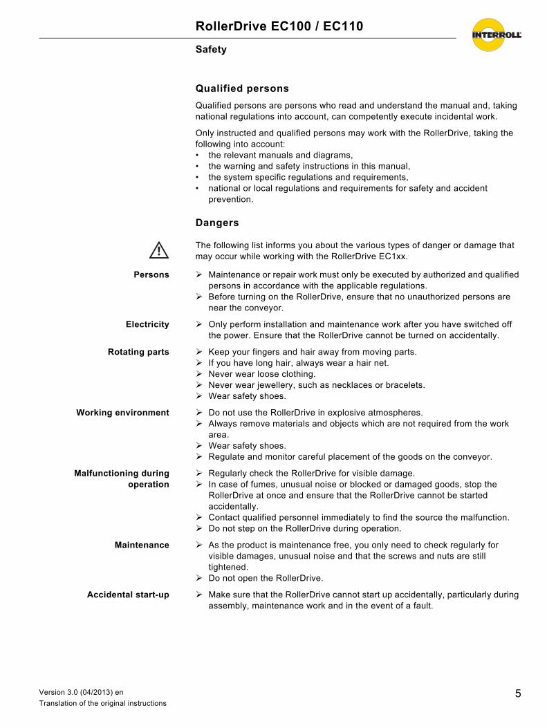
Qualified persons
Qualified persons are persons who read and understand the manual and, taking national regulations into account, can competently execute incidental work.
Only instructed and qualified persons may work with the RollerDrive, taking the following into account:• the relevant manuals and diagrams,• the warning and safety instructions in this manual,• the system specific regulations and requirements,• national or local regulations and requirements for safety and accident
prevention.
Dangers
Persons Maintenance or repair work must only be executed by authorized and qualified persons in accordance with the applicable regulations.
Before turning on the RollerDrive, ensure that no unauthorized persons are near the conveyor.
Electricity Only perform installation and maintenance work after you have switched off the power. Ensure that the RollerDrive cannot be turned on accidentally.
Rotating parts Keep your fingers and hair away from moving parts. If you have long hair, always wear a hair net. Never wear loose clothing. Never wear jewellery, such as necklaces or bracelets. Wear safety shoes.
Working environment Do not use the RollerDrive in explosive atmospheres. Always remove materials and objects which are not required from the work
area. Wear safety shoes. Regulate and monitor careful placement of the goods on the conveyor.
Malfunctioning duringoperation
Regularly check the RollerDrive for visible damage. In case of fumes, unusual noise or blocked or damaged goods, stop the
RollerDrive at once and ensure that the RollerDrive cannot be started accidentally.
Contact qualified personnel immediately to find the source the malfunction. Do not step on the RollerDrive during operation.
Maintenance As the product is maintenance free, you only need to check regularly for visible damages, unusual noise and that the screws and nuts are still tightened.
Do not open the RollerDrive.
Accidental start-up Make sure that the RollerDrive cannot start up accidentally, particularly during assembly, maintenance work and in the event of a fault.
Important
The following list informs you about the various types of danger or damage that may occur while working with the RollerDrive EC1xx.
5Version 3.0 (04/2013) en
Translation of the original instructions

RollerDrive EC100 / EC110
Safety
Interfaces
By assembling the RollerDrive in a conveyor module, potential hazards may occur. These are not described in this manual and have to be analyzed during the design, installation, and startup of the conveyor module.
After assembling the RollerDrive in a conveyor module, check the whole system for any new potential dangerous condition prior to turning on the conveyor.
Operating modes
Normal mode Operation of the installed device at the end customer's as a component in a conveyor in a complete system.
Special mode All operating modes which are required to guarantee and maintain safe and normal operation.
Special operating mode Explanation Comment
Transport/Storage Loading and unloading, transport and storage
-
Assembly/Initial start-up Installation at the end customer's and performing the test run
When de-energized
Cleaning External cleaning When de-energized
Maintenance/Repairs Maintenance and inspection tasks When de-energized
Troubleshooting Troubleshooting in the event of a fault When de-energized
Fault elimination Eliminating the fault When de-energized
Shut-down Dismantling from the conveyor When de-energized
Disposal Disposal of RollerDrive and packaging -
6 Version 3.0 (04/2013) en
Translation of the original instructions

RollerDrive EC100 / EC110
Product information
Components
Product Description
The RollerDrive EC1xx is sealed in accordance with Protection Class IP54.
A corresponding DriveControl is required to operate the RollerDrive EC1xx (see "DriveControls for the RollerDrive EC1xx", page 11).
1 Motor plug with cable2 Motor cartridge shaft3 Fixed bearing housing assembly4 Motor5 Idler cartridge shaft
6 Idler bearing housing assembly7 Tube8 Non-slip drive9 Gearbox
7Version 3.0 (04/2013) en
Translation of the original instructions

RollerDrive EC100 / EC110
Product information
RollerDrive label
The specifications on the RollerDrive label are used to identify the RollerDrive. This is required to use the RollerDrive as intended.
Product identification
To identify a RollerDrive, the following information is required. You may enter the values of your RollerDrive in the last column.
Type plate
1 Manufacturer2 Date of production3 Gear ratio4 Performance
5 Nominal voltage6 Speed range7 Type of RollerDrive8 Serial number
IN
TERROLL
Rolle
rDrive
03/10
9:1
11 W
24 VDC
0,04 –0,90 m/s
BT 100123456789
Interroll Engineering GmbH/D
6
7
8
G
a
Information Possible value Own value
RollerDrive label Motor typeGear ratioSerial number
Tube diameter 50 mm or 1.9 in
Tube material Zinc-plated, galvanized, aluminum or stainless steel (with or without sleeves)
Roller length EL/BF
Roller transmission Torque transmission
Idler cartridge shaft Spring loaded or floating(see "Dimensions of bearing seats on the non-driven side", page 13)
8 Version 3.0 (04/2013) en
Translation of the original instructions
RollerDrive EC100 / EC110
Product information
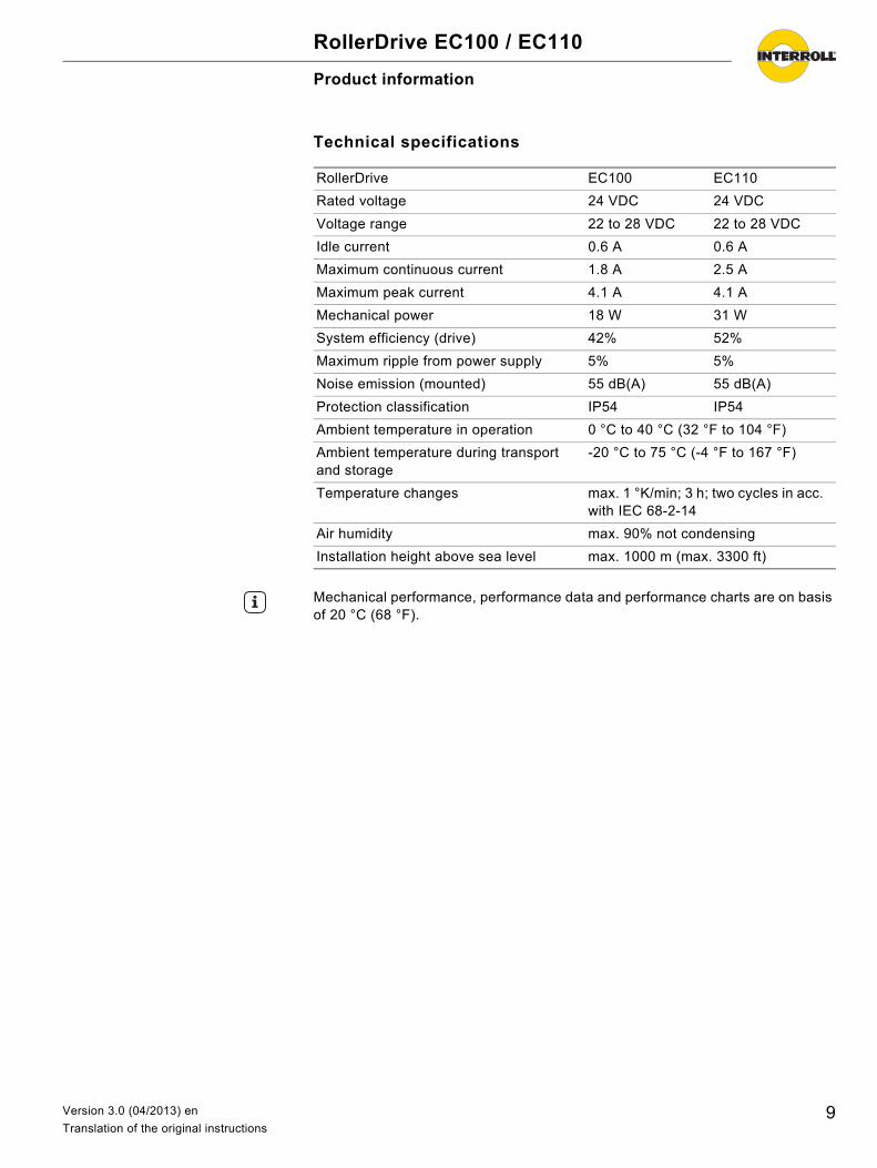
Technical specifications
RollerDrive EC100 EC110
Rated voltage 24 VDC 24 VDC
Voltage range 22 to 28 VDC 22 to 28 VDC
Idle current 0.6 A 0.6 A
Maximum continuous current 1.8 A 2.5 A
Maximum peak current 4.1 A 4.1 A
Mechanical power 18 W 31 W
System efficiency (drive) 42% 52%
Maximum ripple from power supply 5% 5%
Noise emission (mounted) 55 dB(A) 55 dB(A)
Protection classification IP54 IP54
Ambient temperature in operation 0 °C to 40 °C (32 °F to 104 °F)
Ambient temperature during transport and storage
-20 °C to 75 °C (-4 °F to 167 °F)
Temperature changes max. 1 °K/min; 3 h; two cycles in acc. with IEC 68-2-14
Air humidity max. 90% not condensing
Installation height above sea level max. 1000 m (max. 3300 ft)
Hint
Mechanical performance, performance data and performance charts are on basis of 20 °C (68 °F).
9Version 3.0 (04/2013) en
Translation of the original instructions
RollerDrive EC100 / EC110
Product information
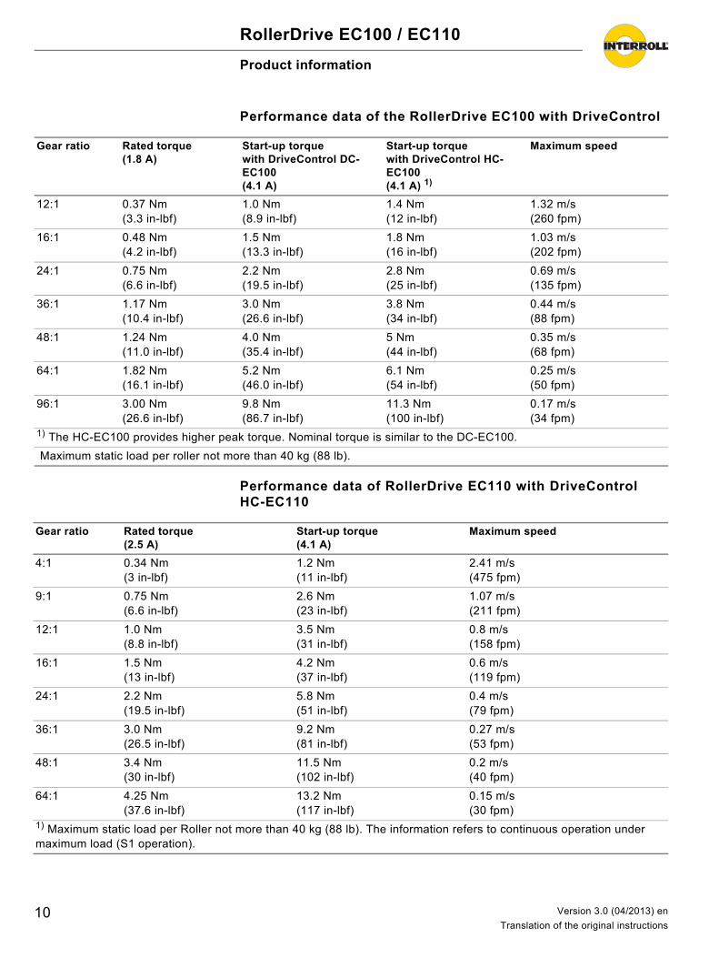
Performance data of the RollerDrive EC100 with DriveControl
Performance data of RollerDrive EC110 with DriveControl HC-EC110
Gear ratio Rated torque (1.8 A)
Start-up torque with DriveControl DC-EC100 (4.1 A)
Start-up torque with DriveControl HC-EC100 (4.1 A) 1)
Maximum speed
12:1 0.37 Nm (3.3 in-lbf)
1.0 Nm (8.9 in-lbf)
1.4 Nm (12 in-lbf)
1.32 m/s (260 fpm)
16:1 0.48 Nm (4.2 in-lbf)
1.5 Nm (13.3 in-lbf)
1.8 Nm (16 in-lbf)
1.03 m/s (202 fpm)
24:1 0.75 Nm (6.6 in-lbf)
2.2 Nm (19.5 in-lbf)
2.8 Nm (25 in-lbf)
0.69 m/s (135 fpm)
36:1 1.17 Nm (10.4 in-lbf)
3.0 Nm (26.6 in-lbf)
3.8 Nm (34 in-lbf)
0.44 m/s (88 fpm)
48:1 1.24 Nm(11.0 in-lbf)
4.0 Nm(35.4 in-lbf)
5 Nm(44 in-lbf)
0.35 m/s(68 fpm)
64:1 1.82 Nm (16.1 in-lbf)
5.2 Nm (46.0 in-lbf)
6.1 Nm (54 in-lbf)
0.25 m/s (50 fpm)
96:1 3.00 Nm(26.6 in-lbf)
9.8 Nm(86.7 in-lbf)
11.3 Nm(100 in-lbf)
0.17 m/s(34 fpm)
1) The HC-EC100 provides higher peak torque. Nominal torque is similar to the DC-EC100.
Maximum static load per roller not more than 40 kg (88 lb).
Gear ratio Rated torque (2.5 A)
Start-up torque (4.1 A)
Maximum speed
4:1 0.34 Nm(3 in-lbf)
1.2 Nm(11 in-lbf)
2.41 m/s (475 fpm)
9:1 0.75 Nm(6.6 in-lbf)
2.6 Nm(23 in-lbf)
1.07 m/s (211 fpm)
12:1 1.0 Nm (8.8 in-lbf)
3.5 Nm (31 in-lbf)
0.8 m/s (158 fpm)
16:1 1.5 Nm (13 in-lbf)
4.2 Nm (37 in-lbf)
0.6 m/s (119 fpm)
24:1 2.2 Nm (19.5 in-lbf)
5.8 Nm (51 in-lbf)
0.4 m/s (79 fpm)
36:1 3.0 Nm (26.5 in-lbf)
9.2 Nm (81 in-lbf)
0.27 m/s (53 fpm)
48:1 3.4 Nm(30 in-lbf)
11.5 Nm(102 in-lbf)
0.2 m/s(40 fpm)
64:1 4.25 Nm (37.6 in-lbf)
13.2 Nm (117 in-lbf)
0.15 m/s (30 fpm)
1) Maximum static load per Roller not more than 40 kg (88 lb). The information refers to continuous operation under maximum load (S1 operation).
10 Version 3.0 (04/2013) en
Translation of the original instructions
RollerDrive EC100 / EC110
Product information
DriveControls for the RollerDrive EC1xx
Interroll recommends using the RollerDrive EC1xx in combination with the corresponding Interroll DriveControl.
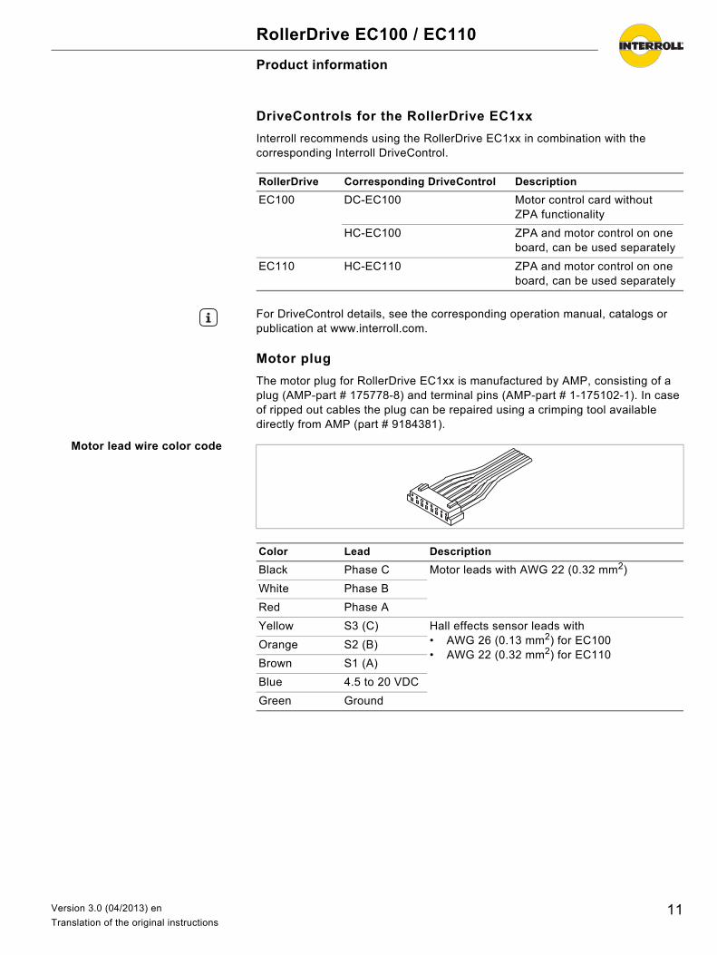
Motor plug
The motor plug for RollerDrive EC1xx is manufactured by AMP, consisting of a plug (AMP-part # 175778-8) and terminal pins (AMP-part # 1-175102-1). In case of ripped out cables the plug can be repaired using a crimping tool available directly from AMP (part # 9184381).
Motor lead wire color code
RollerDrive Corresponding DriveControl Description
EC100 DC-EC100 Motor control card without ZPA functionality
HC-EC100 ZPA and motor control on one board, can be used separately
EC110 HC-EC110 ZPA and motor control on one board, can be used separately
Hint
For DriveControl details, see the corresponding operation manual, catalogs or publication at www.interroll.com.
Color Lead Description
Black Phase C Motor leads with AWG 22 (0.32 mm2)
White Phase B
Red Phase A
Yellow S3 (C) Hall effects sensor leads with• AWG 26 (0.13 mm2) for EC100• AWG 22 (0.32 mm2) for EC110
Orange S2 (B)
Brown S1 (A)
Blue 4.5 to 20 VDC
Green Ground
11Version 3.0 (04/2013) en
Translation of the original instructions

RollerDrive EC100 / EC110
Product information
Dimensions of motor shaft
Standard configuration
EC110 solid hex configuration
20 mm (0.79 in)
26 mm (1.02 in)
6 mm (0.24 in)
EC100: 840 mm (33 in)EC110: 1070 mm (42 in)
AF 11 mm (0.44 in) hex
M12 x 1.5 mm
25 mm (0.98 in)
19 mm (0.75 in)
6 mm (0.24 in)11 mm (0.43 in) hex
840 mm (33 in)
AF 11 mm (0.44 in) hex
M12 x 1.5 mm
12 Version 3.0 (04/2013) en
Translation of the original instructions

RollerDrive EC100 / EC110
Product information
Dimensions of bearing seats on the non-driven side
11 mm (0.44 in) hex, Spring-loaded shaft Female threaded M8 (FTM8),
Straight
Round belt head
PolyVee head
Toothed belt head Poly-Chain GT; 8 mm pitch; 18 teeth
5 mm (0.2 in)
15.5 mm (0.61 in)5 mm (0.2 in)
AF 13 mm (0.51 in)
31 mm (1.22 in)
ø37.8 mm (1.49 in)
4 mm (0.16 in)
11 mm (0.44 in)
←
13.5 mm (0.53 in) 13 mm (0.51 in)
31 mm (1.22 in)
4 mm (0.16 in)
13.5 mm (0.53 in) 13 mm (0.51 in)
AF 19 mm (0.75 in)
ø37.8 mm (1.49 in)
4 mm (0.16 in)
31 mm (1.22 in)
11 mm (0.44 in)
ø43 mm (1.7 in)
4 mm (0.16 in)
31 mm (1.22 in)
ø43 mm (1.7 in)
AF 19 mm (0.75 in)
35 mm (1.38 in)
27.5 mm (1.08 in)
4 mm (0.16 in)
ø45.8 mm (1.8 in)
AF 11 mm (0.44 in) hex
13Version 3.0 (04/2013) en
Translation of the original instructions

RollerDrive EC100 / EC110
Product information
BF/EL = Between Frames / Installation Length
Round belt groove locations
Female thread IGM8, singlebearing
Spring-loaded hex,double bearing
Conical RollerDrives
For conical RollerDrives there must be an 1.8° angle compensation on the motor end to avoid bending forces on the RollerDrive.
Sprocket head 11 mm (0.44 in) hex shaft; 3/8 in pitch; 20 teeth
11 mm (0.44 in) hex, Spring-loaded shaft Female threaded M8 (FTM8),
9.5 mm (0.37 in)
16.8 mm (0.66 in)
35 mm (1.38 in)
ø60.9 mm (2.4 in)
min. 30 mm (1.2 in)min. 30 mm (1.2 in)
for tube diameter 50 mm
for tube diameter 1.9 in
min. 31.75 mm (1.25 in) min. 31.75 mm (1.25 in)
ø38.5 mm (1.52 in)
ø38.1 mm (1.5 in)
min. 30 mm (1.2 in)
for tube diameter 50 mm
for tube diameter 1.9 in
min. 31.75 mm (1.25 in)
min. 50 mm (1.9 in)
min. 54.6 mm (2.15 in)
←
ø38.5 mm (1.52 in)
ø38.1 mm (1.5 in)
Hint
Other tube groove locations are possible.
14 Version 3.0 (04/2013) en
Translation of the original instructions

RollerDrive EC100 / EC110
Product information
Failsafe brake for RollerDrive EC100
Optionally, the RollerDrive EC100 is also available with a failsafe brake (then called EC100B), which is designed to hold the RollerDrive in position in case of a power shut down, mainly at declines. The brake shall be used as holding brake only and not as a dynamic brake (e.g. not for deceleration or positioning).
Recommended break leads connection:• Green lead with red stripes: 24 VDC• Green lead with blue stripes: GND
The fail save brake is not sensitive to electrical polarity, so it can be connected bi polar; for clearness it is recommended to connect them as stated above.
Technical data
1 Brake leads2 Motor plug
Nominal voltage 24 VDC
Voltage range 0 to 28 VDC
Brake locking voltage max. 6.0 VDC
Brake releasing voltage min. 12.2 VDC
Current consumption 0.167 A
Internal resistance 144 Ω
Lead wires AWG 22 Teflon
Gear ratio Static holding torque
24:1 8.4 Nm (74.3 in-lbf)
36:1 12.6 Nm (111.5 in-lbf)
48:1 16.8 Nm (148.7 in-lbf)
64:1 22.4 Nm (198.2 in-lbf)
96:1 33.6 Nm (297.4 in-lbf)
Hint
The RollerDrive EC100 (12:1) and RollerDrive EC100 (16:1) are not available with failsafe brake.
15Version 3.0 (04/2013) en
Translation of the original instructions

RollerDrive EC100 / EC110
Transport and storage
Transport
• Each RollerDrive is covered at its ends with end-protectors.
Do not stack pallets. Check the fixation of the RollerDrives before transport. Avoid hard shocks during transport. Check each RollerDrive visually for damage after transport. In case of damage, take photos of the damaged parts. To maintain the warranty, instantly report any damage caused during
transport to the transport company and to Interroll. Do not transfer the RollerDrives between warm and cold environments as this
may cause condensing water.
Storage
Check each RollerDrive for damage after storage.
Risk of injury due to improper transport Transport may only be carried out by qualified and
authorized persons. Observe the following notices.
CAUTION
Risk of injury due to improper storage Do not stack pallets. Do not stack more than four carton boxes.
CAUTION
16 Version 3.0 (04/2013) en
Translation of the original instructions
RollerDrive EC100 / EC110
Assembly
Warning information for assembly
Do not drop or mishandle the RollerDrive to avoid internal damage. Check each RollerDrive visually for damage before assembly. In order to prevent damage to the internal connections, do not hold, carry or
secure the RollerDrive by the motor cable. Do not force the RollerDrive when inserting it into the conveyor frame. It
should fit easily into the holes in the frame. Ensure that the proper tightening torque is applied to the RollerDrive hex nut
to prevent the shaft spinning in the frame and the wires twisting (see "Securing the RollerDrive in the conveyor frame", page 21).
Do not twist the motor cable.
Rotating partsRisk of pinched fingers
Do not insert fingers between the RollerDrive and the round belt, PolyVee belt or roller chain.
Install a protection device (such as a guard plate) to prevent fingers from getting trapped in the round belt, PolyVee belt or roller chain.
Install an appropriate warning on the conveyor.
Risk of damage leading to failure or shortened life expectancy of the RollerDrive Follow the instructions below.
CAUTION
17Version 3.0 (04/2013) en
Translation of the original instructions
RollerDrive EC100 / EC110
Assembly
Warning notices for the electrical installation
The electrical installation may only be executed by qualified and authorized persons.
Disconnect the power before installing, removing or rewiring the RollerDrive. Do not apply AC current to the RollerDrive or DriveControl device at any time,
as this will cause irreparable damage. Do not apply too much tension and pressure stress to the motor connector.
Bending the cable and forcing the star washer over the cable can cause damage to the insulation of the cable, which could result in failure of the RollerDrive.
Ensure that the RollerDrive, the DriveControl and the 24 VDC power source are properly earthed through the frame or supporting structure in which the RollerDrive and the DriveControl are installed. Incorrect earthing can result in the buildup of static charge, which can cause the motor or DriveControl to malfunction or fail prematurely.
Do not bend the motor cable at the motor shaft. Leave a minimum of 12 mm (0.5 in) of excess cable for stress relief. (Maintain a bending radius of at least five times the cable diameter.)
Do not rotate the RollerDrive manually, as this generates a voltage which could damage the DriveControl.
Risk of damage to the motor and/or the wires of the RollerDrive Observe the following notices.
18 Version 3.0 (04/2013) en
Translation of the original instructions

RollerDrive EC100 / EC110
Assembly
RollerDrive installation
Inserting the motor shaft Remove the shipping tube from the RollerDrive.
Place the first star washer on the motor shaft.
Pass the motor cable through the 11 mm (0.44 in) hex hole in the conveyor frame and insert the motor shaft into the hex hole.
Fit one or two round belts, size 4 mm, max. 5 mm (3/16 in) or RollerDrive belts (if used) on the non-driven end of the RollerDrive.
Hint
Use caution when cutting the tie-wrap from the harness. Do not cut any of the sleeving or cables on the unit.
Hint
To pass the motor plug through holes, fold the motor cable as follows.
Internal damage of the RollerDrive due to improper handling Do not install the securing hardware at this time. Do not bend the motor cable at the motor shaft. Leave a
minimum of 12 mm (0.5 in) of excess cable for stress relief.
Motor cable
Motor plug
19Version 3.0 (04/2013) en
Translation of the original instructions

RollerDrive EC100 / EC110
Assembly
Inserting the idler shaft How the idler shaft is inserted in the conveyor frame depends on the idler shaft option. The easiest installation option is the spring-loaded shaft option.
Inserting the spring-loaded idler shaft
Push the spring-loaded idler shaft inwards and align the shaft with the hole in the frame.
Release the idler shaft and allow it to pop into the hole in the frame.
Inserting the FTM8 idler shaft
Place a split lock washer onto a M8x20 bolt. Align the RollerDrive with the hole in the frame and thread the M8 bolt and
split lock washer into the shaft. Use a wrench to prevent the shaft pin from turning (width across flats AF 13 mm or AF 19 mm, depending on the shaft pin type, see "Round belt groove locations", page 14).
Use a torque wrench to tighten the bolt with 20 Nm (177 in-lbf) until the split washer is completely compressed.
20 Version 3.0 (04/2013) en
Translation of the original instructions

RollerDrive EC100 / EC110
Assembly
Securing the RollerDrive inthe conveyor frame
There is a nut and a washer on the shaft next to the tube. This inner nut has been preassembled and secured in the correct position.
Use a flat wrench AF 19 mm to prevent the inner nut from turning. Use a wrench site AF 36 mm in the case of the IP66 configuration.
Slip a second washer and a hex nut over the motor cable and screw it onto the threaded motor shaft. Ensure that washers are fitted on both sides of the profile.
Use a torque wrench to tighten this outer nut with 35 Nm (308 in-lbf) while ensuring that the inner nut is not rotating.
Mounting tool
For mounting the PolyVee belt, you may want to build a mounting tool as shown in the figure below.
Place the mounting tool between two rollers to reduce the gap between the adjacent rollers.
Hint
Do not adjust the inner nut and washer.
Hint
To prevent bending forces on conical RollerDrives, an angular compensation on the motor end is needed.
Hint
Dimensions of the mounting tool depend on the roller pitch and the roller tube diameter.
21Version 3.0 (04/2013) en
Translation of the original instructions

RollerDrive EC100 / EC110
Assembly
Anti-spin bracket
The following torque lock must be employed when using the unthreaded hexagonal shaft on the motor side.
Dimensions of the anti-spinbracket (flat up version)
Bill of material of the anti-spinbracket
Mounting the anti-spinbracket
Ensure that the power of the motor control board is switched off and that it cannot be switched on accidentally.
If connected, disconnect the motor leads from the motor control board. Slide the template over the motor leads and onto the hex shaft. Use the template to mark the center of the mounting holes.
Remove the template from the hex shaft and the motor leads. Drill two ø 7 mm (0.275 in) mounting holes at the marked spots and remove
burrs from the rear side of the holes. Slide the anti-spin bracket with the flat side facing the conveyor frame over
the motor leads and onto the hex shaft. Put two serrated flange hex cap screws in the bottom holes of the anti-spin
bracket and tighten them with the hex tooth washer nuts.
11.2
mm
(0.4
4 in
)ø 7 mm (0.275 in)
3.3 mm (0.13 in)
62.8 mm (2.47 in)
44.5
mm
(1.
75 in
)
34 m
m (
1.34
in)
45 mm (1.77 in)
No. Description Quantity
1 Anti-spin bracket 1
2 Template 1
3 1/8" Allen key 1
4 Button head screw 1
5 Serrated flange hex cap screw 2
6 Hex tooth washer nut 2
22 Version 3.0 (04/2013) en
Translation of the original instructions

RollerDrive EC100 / EC110
Assembly
Install the button head screw in the upper hole of the anti-spin bracket to secure the shaft to the anti-spin bracket.
Electrical installation
If you use the recommended DriveControl (see "DriveControls for the RollerDrive EC1xx", page 11), connect the motor plug to the DriveControl.
If you do not use the DriveControl, connect your control to the pins of the motor plug (for the pin definition see "Motor plug", page 11)
23Version 3.0 (04/2013) en
Translation of the original instructions

RollerDrive EC100 / EC110
Initial startup and operation
Initial startup
Inspections before initialstartup
Ensure that no objects are in contact with rotating or moving parts. Ensure that all bolts are tightened according to the specifications. Ensure that no additional dangerous areas arise due to interfaces with other
components. Ensure that the wiring is in accordance with specifications and legal
guidelines. Check all protection devices. Ensure that no bystanders are in dangerous areas around the conveyor.
Operation
Inspections before everystartup
Check the RollerDrive for visible damage. Check all protection devices. Ensure that no bystanders are in dangerous areas around the conveyor. Clearly specify and monitor the way goods are placed on the conveyor. Make sure that the RollerDrive is not blocked.
Procedure in case of accident or malfunction
Stop the conveyor at once and ensure that it cannot be started accidentally. In case of an accident: Provide first aid and call for emergency assistance. Inform responsible persons. Have the malfunction repaired by qualified persons. Start the conveyor only after this has been approved by qualified persons.
Hint
For information about startup, see the manual for the DriveControl or your control.
Rotating parts and accidental start-upRisk of pinched fingers
Do not insert fingers between the RollerDrive and the round belt, PolyVee belt or roller chain.
Do not remove the protection device. Keep fingers, hair and loose clothing away from the
RollerDrive.
Damage to the motor or the control due to induction Do not push items along the roller conveyor by hand. Do not spin the RollerDrive manually.
CAUTION
Hint
Ambient conditions during operation see "Technical specifications", page 9
24 Version 3.0 (04/2013) en
Translation of the original instructions
RollerDrive EC100 / EC110
Maintenance and cleaning
Warnings concerning maintenance and cleaning
Maintenance
Checking the RollerDrive If the RollerDrive is not secured as specified in the installation instructions (see "Assembly", page 17), it may rotate in the hole in the conveyor frame. This will result in the roller leads becoming twisted and eventually severed.
Monthly check the RollerDrive for visible damage. Annually ensure that the roller shaft is secured properly in the conveyor
frame.
Replacing a RollerDrive If a RollerDrive is damaged or broken down, it has to be replaced.
Install a new RollerDrive (see "Abandonment", page 27 and see "RollerDrive installation", page 19).
Cleaning
Increased surface friction reduces the roller speed since more power is used to overcome the resistance. Therefore, in a dirty environment, periodic cleaning will ensure good contact with the goods and reduce friction.
Remove foreign materials and dirt with a simple cleaning brush (not a wire brush) by brushing gently.
Remove smaller amounts of dirt with a damp cloth. When doing this, make sure that wetting of the RollerDrive is no more than slightly damp.
Do not use sharp-edged tools to clean the roller.
Risk of injury due to improper handling or accidental motor starts Maintenance work and cleaning may only be executed
by qualified and authorized persons. Only perform maintenance work after switching off the
power. Ensure that the RollerDrive cannot be turned on accidentally.
Set up signs indicating maintenance work.
CAUTION
25Version 3.0 (04/2013) en
Translation of the original instructions

RollerDrive EC100 / EC110
Troubleshooting
Troubleshooting
Risk of injuries due to incorrect handling Troubleshooting may only be done by qualified and
authorized persons. Only perform troubleshooting after switching off the
power. Ensure that the RollerDrive cannot be turned on
accidentally.
CAUTION
Symptom Possible cause Help
RollerDrive is not operating No power supply Check 24 VDC power supply at the DriveControl.
Plugs not connected properly Check cable connection.
RollerDrive is rotating in the wrong direction.
Wrong direction settings Change setting of direction switch on DriveControl.
RollerDrive is rotating at the wrong speed.
Wrong speed settings Change setting of potentiometer on DriveControl.
Abnormal noise coming out of the RollerDrive
Motor or gearbox is damaged Replace the RollerDrive.
Interrupted RollerDrive operation Damaged motor cable Check motor cable for damage.If the motor cable is damaged, replace the RollerDrive.
26 Version 3.0 (04/2013) en
Translation of the original instructions

RollerDrive EC100 / EC110
Abandonment and disposal
Abandonment
Disconnect the motor cable from the control. Unscrew the outer nut at the threaded motor shaft. If the RollerDrive has a spring-loaded idler shaft, push the idler shaft inwards. If the RollerDrive has a FTM8 idler shaft, unscrew the bolt at the idler shaft. Extract the RollerDrive from the conveyor frame.
Disposal
The operator is responsible for the proper disposal of the RollerDrive. In doing so, industry-specific and local provisions must be observed for the disposal of the RollerDrive and its packaging.
Risk of injury due to improper handling Abandonment may only be executed by qualified and
authorized persons. Only abandon the RollerDrive after switching off the
power. Ensure that the RollerDrive cannot be turned on accidentally.
CAUTION
27Version 3.0 (04/2013) en
Translation of the original instructions

RollerDrive EC100 / EC110
Appendix
Accessories
Belt
DriveControls
Anti-spin bracket
Part Description
Toothed belt • Gates Poly-Chain GT or similar: pitch 8 mm (0.31 in)• Toothed belt width: 11.2 mm (11.18 mm) • Hub with 18 teeth
Round belt • Belts of 4 mm (0.16 in) and max. 5 mm (0.20 in) diameter
PolyVee belt • Drive head with 9 grooves for flexible V-ribbed belts • PJ form, ISO 9981, DIN 7867 • pitch 2.34 mm (2.29 mm) • Belts with a max. of 4 ribs
Part Description Part #
DC-EC100 Motor control card (without ZPA functionality) 8996
HC-EC100 HybridControl with ZPA and motor control on one board, but can be used separately
9000
HC-EC100 Full HybridControl with ZPA, motor control and digital I/O handshake
9001
HC-EC110 HybridControl with ZPA and motor control on one board, but can be used separately
9004
Part Description Part #
Anti-spin bracket flat up Bottom and top of hex are flat N582
Anti-spin bracket point up Bottom and top of hex are pointed N583
28 Version 3.0 (04/2013) en
Translation of the original instructions

RollerDrive EC100 / EC110
Appendix
Installation Declaration
in accordance with the EC Machinery Directive 2006/42/EC, Appendix II B
The manufacturer:
hereby declares with sole responsibility that the product range
• RollerDrive EC1xx
is not a ready-to-use machine as defined by the EC Machinery Directive and, therefore, does not fully comply with the requirements of this directive. Initial start-up of these conveyor modules is not permitted until conformity of the entire machine/system in which they are installed has been declared via the EC Machinery Directive.
The health and safety requirements as stated in Appendix I have been applied. The special technical documents as stated in Appendix VII B have been compiled and will be sent to the responsible authority if necessary.
Person authorized to compile the technical documents: Georg Malina, Interroll Engineering GmbH, Hoeferhof 16, D - 42929 Wermelskirchen
Applied EC directives:• Machinery Directive 98/37/EC with the amendment 98/79/EC • EMC Directive 2004/108/EC • RoHS Directive 2002/95/EC
Applied harmonized standards:• EN ISO 12100 Parts 1 and 2 "Safety of machinery - Basic concepts, general
principles for design" - Part 1: "Basic terminology, methodology" - Part 2: "Technical principles"
Wermelskirchen, 31st March 2010
Armin Lindholm
(Managing Director)
(This declaration can be obtained at www.interroll.com, if needed.)
Interroll Engineering GmbH Hoeferhof 16 D - 42929 WermelskirchenGermany
29Version 3.0 (04/2013) en
Translation of the original instructions

E u r o p e
AustriaTel +49 2193 23 [email protected]
BelgiumTel. +49 2193 23 [email protected]
Czech RepublicInterroll CZ, s.r.o.Na Řádku 7/317269002 BřeclavCzech RepublicTel + 420 519 330 [email protected]
DenmarkInterroll Nordic A/S Hammerholmen 2-62650 HvidovreDenmarkTel + 45 36 88 33 [email protected]
FinlandInterroll Nordic A/SMartinkyläntie 5301720 VantaaFinlandTel + 358 9 54 94 94 [email protected]
FranceInterroll SAS Z.I. De Kerannou-BP3429250 Saint-Pol-de-LeonFranceTel + 33 2 98 24 [email protected]
GermanyInterroll Fördertechnik GmbH Höferhof 1642929 WermelskirchenGermanyTel + 49 2193 23 [email protected]
HungaryLörincz Kft. Kastély U.27Pf. 572045 TörökbálintHungaryTel + 36 23 337 [email protected]
IcelandIBH ehfDugguvogur 10104 ReykjavikIcelandTel + 354 562 [email protected]
ItalyRulli Rulmeca S.P.A. Via Arturo Toscanini 124011 Almé (Bg)ItalyTel + 39 035 43 00 [email protected]
LuxembourgTel +49 2193 23 [email protected]
NetherlandsTel +49 2193 23 [email protected]
NorwayInterroll A/SKobbervikdalen 653036 DrammenNorwayTel + 47 32 88 26 [email protected]
PolandInterroll Polska Sp. z o.o.ul. Płochocińska 8503-044 WarszawaPolandTel +48 22 741 741 [email protected]
PortugalRulmeca de Portugal, LDAParque Industrial do TortosendoEdifício Parkurbis, Loja 7Apartado 1136200-865 TortosendoPortugalTel +351 275 33 07 [email protected]
RomaniaKrako International SRLStr. Sfanta Maria 1-5Bl. 10A4Sc 1 Apt 4 Sector 1001494 BucurestiRomaniaTel + 40 21 260 [email protected]
Slovenia3-TEC, prehrambena-tehnologija-hlajenjeDravska ulica 71000 LjubljanaSlovenijaTel + 386 1 56 56 [email protected]
SpainInterroll España S.A. Parc Tecnològic del VallèsC/Dels Argenters, 5 Edificio 1 Bp y Cp08290 Cerdanyola del VallèsBarcelonaSpainTel + 34 90 211 [email protected]
SwedenInterroll Nordic A/S Karlsrovägen 64302 41 HalmstadSwedenTel + 46 35 227 [email protected]
SwitzerlandTel. +49 2193 23 [email protected]
United KingdomInterroll Ltd.Brunel RoadCorby, Northants NN17 4UXUnited KingdomTel + 44 1536 200 [email protected]
A f r i c a
South AfricaInterroll South Africa (Pty) Ltd Box 327Isando 1600GautengSouth AfricaTel + 27 11 281 99 00za sales@interroll com
N o r t h a n d S o u t h A m e r i c a
CanadaInterroll Checkstand8900 Keele StreetUnit 2 & 3Concord, Ontario L4K 2N2CanadaTel +1 905 660 [email protected]
Interroll Canada Ltd. 1201 Gorham StreetNewmarket Ontario L3Y 8Y2CanadaTel +1 905 727 33 [email protected]
USAInterroll Corporation3000 Corporate DriveWilmington, N.C. 28405USATel +1 910 799 [email protected]
Interroll Automation LLC 5035 Keystone BoulevardJeffersonville, IN 47130USATel +1 812 284 [email protected]
Interroll Dynamic Storage, Inc.232 Duncan CircleHiram, GA 30141USATel +1 770 943 15 [email protected]
BrazilInterroll LogísticaElementos para SistemasTransportadores LtdaRua Dom João VI555 - Parque Industrial SAPindamonhangaba - SPCEP 12412- 805BrazilTel + 55 (0)12 3648 [email protected]
A s i a
ChinaInterroll (Suzhou) Co. Ltd.Block B & C Ecological Science HubNo. 1 Ke Zhi RoadSuzhou Industrial ParkJiangsu ProvinceChinaPostal Code: 215021Tel + 86 512 [email protected]
IndiaInterroll Drives and Rollers India Pvt. Ltd. No. 276, 4th main, 4th phasePeenya Industrial AreaBangalore-560058IndiaTel + 91080 [email protected]
IsraelComtrans-Tech Ltd.P.O.B. 17433Tel-Aviv 61174IsraelTel + 972 54 [email protected]
JapanInterroll Japan Co. Ltd. 302-1 ShimokuzawaMidori-kuSagamihara-shiKanagawa 252- 0134JapanTel + 81 42 764 [email protected]
KoreaInterroll (Korea) Co. Ltd.Rm 301 Dongsan Bldg. 333-60Shindang-Dong100-826 Choong Ku, SeoulTel + 82 2 2231 19 [email protected]
SingaporeInterroll (Asia) Pte. Ltd.386 Jalan Ahmad Ibrahim Jurong629156 SingaporeRepublic of SingaporeTel + 65 6266 [email protected]
Sri LankaColombo Machinery & Equipment Ltd.No: 102, Fife Road Colombo 05 Sri LankaTel + 94 11 250 0078/[email protected]
TaiwanFirst Auto-Transfer Equipment Co. Ltd 8F-3, No: 65, Song De Road Hsin Yi DistrictTaipei 11076TaiwanTel + 886 2 27 59 88 [email protected]
ThailandInterroll (Thailand) Co. Ltd. 700/685, Moo 1 Amata NakornPanthong, Chonburi20160ThailandTel + 66 3 844 [email protected]
A u s t r a l i a a n d N e w Z e a l a n d
AustraliaInterroll Australia Pty. Ltd.70 Keon ParadeThomastownVictoria 3074AustraliaTel + 61 3 94 60 21 [email protected]
New ZealandAutomation Equipment (NZ) Ltd. 26 Tawn Place,Pukete, HamiltonNew ZealandTel + 64 (7) 849 [email protected]
HeadquarterInterroll (Schweiz AG)+ 41 91 850 25 [email protected]
www.interroll.com
Version 3.0 (04/2013) en
Translation of the original instructions