user manual - instytut rozrodu zwierząt i badań...
TRANSCRIPT
User Manual
Saturn™ Laser System
RI IMSI™
RI Viewer™

CONTENTS
SECTION 1 5
Preface 5
SECTION 2 6
Introduction to Saturn™ Laser Systems 6Intended Use 6Applicable Part Numbers 6Microscope Compatibility 6Installation 7
SECTION 3 8
Saturn™ Laser Systems Safety Precautions 8Safety 8Precautions 9Guidance and Manufacturer’s Declaration – Electromagnetic Emissions (IEC 6060 1-1-2) 10Guidance and Manufacturer’s Declaration — Electromagnetic Immunity 11Guidance and Manufacturer’s Declaration — Electromagnetic Immunity 12User Interface Icons 13Symbols 14
SECTION 4 15
Saturn™ Laser Systems Product Overview 15Hardware Overview 15Saturn™ Laser System Component Part Numbers 16Saturn™ Laser System Mirror Module Part Number and Descriptions 16Saturn Active™ Mirror Modules 16Packaging and Handling Requirements 16Saturn™ Mirror Modules 17Laser Specifications 18Laser Specifications 18Ablation Laser 18Pilot Laser 18Objective Specifications 18Electrical Specifications 18Dimensions 18Operating Range 18
SECTION 5 19
RI Viewer™ 19Introduction 19How to View Live Images 19
How to Zoom & Pan the Image 19Changing Camera Settings 19How to Take a Picture 20How to Record Video 20How to Perform Measurements 20
SECTION 6 21
Saturn™ Laser Systems Operation 21How to Configure the Laser for a New Procedure 21How to Check Objective Calibration 21How to Check Laser Target Alignment 21How to Check Hole Size Calibration 22How to Remove a Point from the Hole Size Calibration Graph 22How to Fire the Laser (Single Pulse) 23How to Adjust Hole Size/Pulse Width 23Laser Target 23Exclusion Zone 23Hole Size Indicator 23Preset Pulse Lengths 24How to Shut Down 24
SECTION 7 25
Assisted Hatching Procedure 25Introduction 25Summary 25Ablation Procedure 26
SECTION 8 28
Saturn™ Laser Systems Additional Modes 28USA Clearance Regulations 28How to Enable Biopsy Mode 28How to Enable Multi-Pulse Mode 28How to Fire the Laser (Biopsy Mode) 28How to Fire the Laser (Multi-Pulse Mode) 29
SECTION 9 30
Saturn™ Laser Systems Troubleshooting 30Problem 30Possible Cause 30Solution 30
CONTENTS
SECTION 10 31
RI IMSI™ 31Introduction 31Specifications 31Hardware Overview 31Condenser 31Objectives 31IMSI Monitor 32Monitor Settings (for Medical Monitor Supplied by RI) 32Sample Preparation 32Observation 32Maintenance 33Troubleshooting 34Problem 34Possible Cause 34Solution 34
SECTION 11 35
Appendices 35How to Select Cameras 35Camera Flipping 35How to Set the Preset Zoom 35How to Configure the Foot Pedal/Keyboard 35How to View Still and Recorded Images 35How to Select Objectives 36How to Add Objectives 36How to Remove Objectives 36
SECTION 12 37
Saturn™ Laser Systems Care And Maintenance 37Disposal of Goods 37
SECTION 13 38
Returns Procedure 38Research Instruments Ltd 38Customer Feedback 38
CONTENTS
1
Research Instruments Ltd
5
Section 1
PREFACE
This manual is the sole property of Research Instruments, and along with the Research Instruments products to which it applies, is provided for the exclusive use of Research Instruments clients.
In no event does Research Instruments assume the liability for any technical or editorial errors of commission, or omission; nor is Research Instruments liable for direct, indirect, incidental, or consequential damages arising out of the use or inability to use this manual.
© This manual is protected by copyright, all rights reserved, and no part hereof may be photocopied or reproduced in any form without the prior written consent of Research Instruments.
Saturn™, RI Viewer™ and RI IMSI™ are trademarks of Research instruments Ltd. All other brand names are trademarks of their respective owners.
The information in this manual is current at the time of publication. Our commitment to product improvement requires that we reserve the right to change equipment, procedures and specifications at any time.
Note Assisted Hatching is not recommended for routine use in all ART patients.
The system should be operated by qualified and trained personnel only.

Introduction to Saturn™ Laser Systems
2
6
Section 2
INTRODUCTION TO SATURN™ LASER SYSTEMS
Intended UseThe Saturn™ Laser System is intended ‘to ablate a User defined section of a gamete or embryo within ART’.
Applicable indications for use are subject to the regulations of the country into which the device is sold. Availability of a Saturn™ Laser System for clinical use is dependent on the regulatory approval status of the Saturn™ Laser System within the country the device is intended to be sold into.
USA ONLY Ref: FDA 510(k) K060764 and K083208.
The Saturn™ Laser System is to be used to drill a small tangential hole in, or to thin, the zona pellucida of the embryo in selected in vitro fertilization (IVF) patients with otherwise poor prognosis for successful pregnancy outcome such as:
Advanced maternal age
Prior failed IVF
Cryopreserved embryos
Abnormal zona pellucida morphology
Only
Caution: Federal law restricts this device to sale by or on the order of a physician or a practitioner trained and certified in its use
Applicable Part Numbers6-47-500 - Saturn 5 Active™ Laser
6-47-501 - Saturn 5™ Fixed Laser
6-47-510 - Saturn 5 Active™ Laser competitor replacement
6-47-511 - Saturn 5™ Fixed Laser competitor replacement
6-47-512 - Upgrade from Saturn™ to Saturn 5 Active™
6-47-513 - Upgrade from Saturn™ to Saturn 5™ Fixed
6-47-514 - Upgrade from Saturn 3 Active™ to Saturn 5 Active™
6-47-515 - Upgrade from Saturn 5™ Fixed to Saturn 5 Active™
Microscope CompatibilityZeiss Axiovert 40/100/200/Observer
Nikon TMD, D200/300, TE200/300, TE2000, Ti
Leica DMIRB, DMI3000B/4000B/6000B, DMIL
Olympus IMT2, IX50/70, IX51/71/81, IX53/73/83
0120

Section 2
2
Research Instruments Ltd
7
InstallationInstallation of the Saturn™ Laser System should be carried out by a Research Instruments technician or other RI-authorised personnel. Incorrect installation could result in reduced power output, laser misalignment or laser malfunction.
All relevant sections of this manual should be read and understood fully before any operation of the Saturn™ Laser System takes place. If the operator is unsure of any of the information contained in this manual, they should contact Research Instruments or an appointed representative before attempting to use this equipment.
A Patients’ Guide to Laser Assisted Hatching (LAH) is provided on the RI Viewer™ installation CD (LAH Patients Guide.pdf). This can be opened using Adobe Reader or other PDF viewers. We recommend that copies are printed and made available to patients.
For outside of the USA an installation manual will be supplied (6-47-500IM)
No user serviceable parts.
Saturn™ Laser Systems Safety Precautions
3
8
Section 3
SATURN™ LASER SYSTEMS SAFETY PRECAUTIONS
Safety
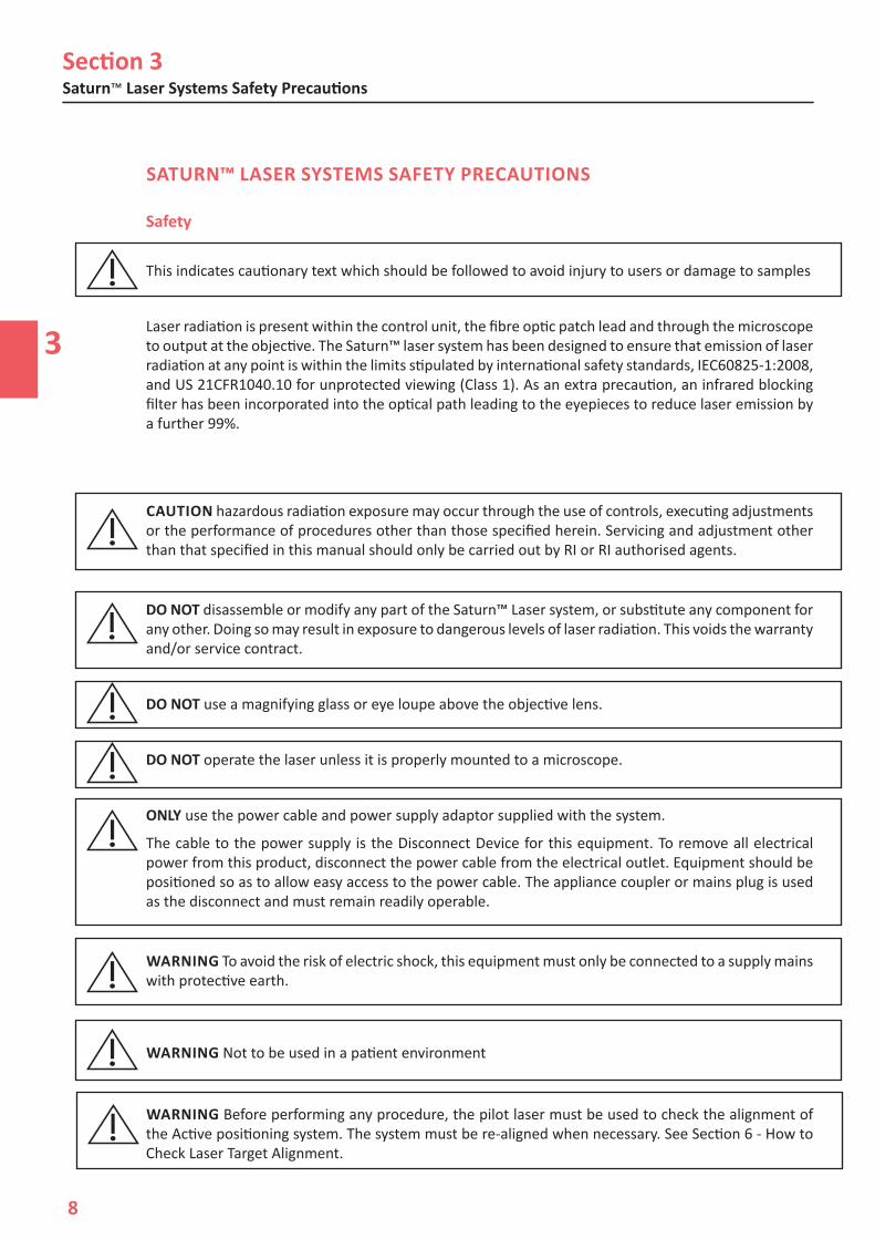
This indicates cautionary text which should be followed to avoid injury to users or damage to samples
Laser radiation is present within the control unit, the fibre optic patch lead and through the microscope to output at the objective. The Saturn™ laser system has been designed to ensure that emission of laser radiation at any point is within the limits stipulated by international safety standards, IEC60825-1:2008, and US 21CFR1040.10 for unprotected viewing (Class 1). As an extra precaution, an infrared blocking filter has been incorporated into the optical path leading to the eyepieces to reduce laser emission by a further 99%.
CAUTION hazardous radiation exposure may occur through the use of controls, executing adjustments or the performance of procedures other than those specified herein. Servicing and adjustment other than that specified in this manual should only be carried out by RI or RI authorised agents.
DO NOT disassemble or modify any part of the Saturn™ Laser system, or substitute any component for any other. Doing so may result in exposure to dangerous levels of laser radiation. This voids the warranty and/or service contract.
DO NOT use a magnifying glass or eye loupe above the objective lens.
DO NOT operate the laser unless it is properly mounted to a microscope.
ONLY use the power cable and power supply adaptor supplied with the system.
The cable to the power supply is the Disconnect Device for this equipment. To remove all electrical power from this product, disconnect the power cable from the electrical outlet. Equipment should be positioned so as to allow easy access to the power cable. The appliance coupler or mains plug is used as the disconnect and must remain readily operable.
WARNING To avoid the risk of electric shock, this equipment must only be connected to a supply mains with protective earth.
WARNING Not to be used in a patient environment
WARNING Before performing any procedure, the pilot laser must be used to check the alignment of the Active positioning system. The system must be re-aligned when necessary. See Section 6 - How to Check Laser Target Alignment.

Section 3
3
Research Instruments Ltd
9
WARNING Thermal lensing is a defocusing of the laser beam caused by changes to the refractive index of the medium as it is heated. The degree of defocus depends on the total beam energy deposited in the medium. While slight defocus has no effect on the drilling properties, this effect may become a problem for higher beam energies. To eliminate any significant effects from thermal lensing, we recommend that the pulse length be kept below 1000μs for clinical Laser Assisted Hatching (LAH) zona drilling.
WARNING Only a single opening should be made in the zona pellucida. Multiple openings or those that are too small may prevent embryo hatching or lead to abnormal development.
WARNING Do not operate the pilot laser with an embryo in the field of view. Exposure to the pilot laser may damage the embryo.
WARNING The microscope itself must be maintained to a high standard. Problems such as worn focus mechanisms or an insecure video camera may lead to unreliable focus and image stability, and could lead to embryo damage.
WARNING Do not operate the laser without the RI Viewer™ software running, as targeting and hole size indication will not be active, and the embryo may be damaged.
WARNING The embryo may be damaged if objectives other than the red Saturn™ laser objective is used.
WARNING Do not modify this equipment without authorization of the manufacturer.
WARNING Where an ITO glass heated stage is fitted, do not fire the laser with the microscope focussed into the ITO glass surface as this may damage the ITO coating.
Precautions• To minimise the risk of damage to blastomeres, administer as few laser pulses as possible at the
lowest energy levels possible to achieve the prescribed zona drilling or thinning effect.
• Direct the laser beam toward a section of the zona pellucida where the adjacent perivitelline space is widest or next to an area of fragmentation.
• A holding pipette should be used during laser treatment to minimize the risk of embryo movement.
• Small openings in the zona pellucida may lead to embryo constriction and abnormal development.
• To date there are no known reports showing a greater occurrence rate of major or minor defects in children derived from laser-hatched embryos. Long-term follow-up data on children born from laser-hatched embryos does not yet exist. A study of 134 such babies* found no increase in the major congenital malformations, chromosomal aberrations or minor congenital malformations between the LAH treated group and all deliveries at their hospital.
• The device is not affected by and does not present any reciprocal interference to the microscope.
• During normal use there is no contact with patient/sample. Standard lab cleaning procedures can be applied.
*Kanyo, K., Konc, J. “A follow-up study of children born after diode laser assisted hatching.” European Journal of Obstetrics and Gynaecology. 110: 176-180 (2003).
Section 3Saturn™ Laser Systems Safety Precautions
3
10
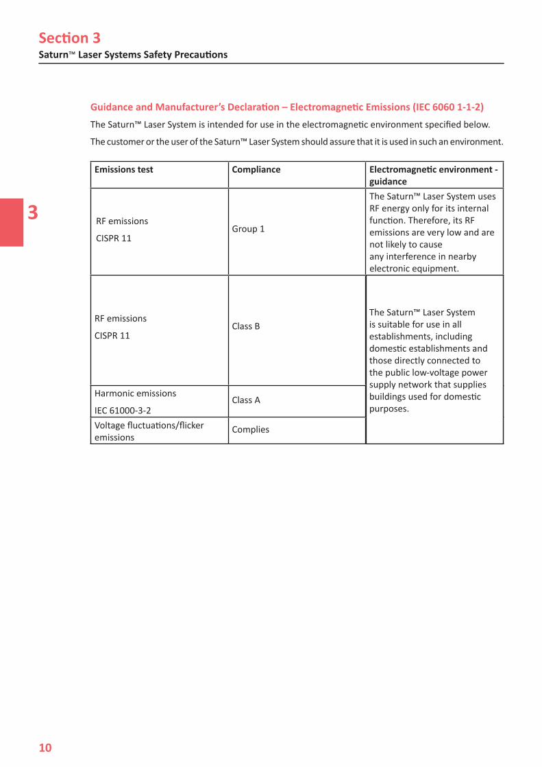
Emissions test Compliance Electromagnetic environment - guidance
RF emissions
CISPR 11Group 1
The Saturn™ Laser System uses RF energy only for its internal function. Therefore, its RF emissions are very low and are not likely to cause any interference in nearby electronic equipment.
RF emissions
CISPR 11Class B
The Saturn™ Laser System is suitable for use in all establishments, including domestic establishments and those directly connected to the public low-voltage power supply network that supplies buildings used for domestic purposes.
Harmonic emissions
IEC 61000-3-2Class A
Voltage fluctuations/flicker emissions
Complies
The Saturn™ Laser System is suitable for use in all establishments, including domestic establishments and those directly connected to the public low-voltage power supply network that supplies buildings used for domestic purposes.
Guidance and Manufacturer’s Declaration – Electromagnetic Emissions (IEC 6060 1-1-2)The Saturn™ Laser System is intended for use in the electromagnetic environment specified below.
The customer or the user of the Saturn™ Laser System should assure that it is used in such an environment.
Section 3
3
Research Instruments Ltd
11
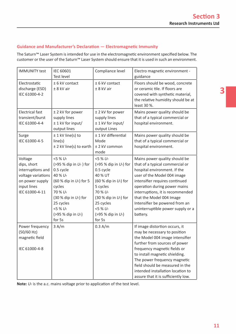
Guidance and Manufacturer’s Declaration — Electromagnetic ImmunityThe Saturn™ Laser System is intended for use in the electromagnetic environment specified below. The customer or the user of the Saturn™ Laser System should ensure that it is used in such an environment.
IMMUNITY test IEC 60601Test level
Compliance level Electro magnetic environment - guidance
Electrostatic discharge (ESD)IEC 61000-4-2
± 6 kV contact± 8 kV air
± 6 kV contact± 8 kV air
Floors should be wood, concrete or ceramic tile. If floors are covered with synthetic material, the relative humidity should be at least 30 %.
Electrical fast transient/burstIEC 61000-4-4
± 2 kV for power supply lines± 1 kV for input/output lines
± 2 kV for power supply lines± 1 kV for input/output Lines
Mains power quality should be that of a typical commercial or hospital environment.
SurgeIEC 61000-4-5
± 1 kV line(s) to line(s)± 2 kV line(s) to earth
± 1 kV differentialMode± 2 kV common mode
Mains power quality should be that of a typical commercial or hospital environment.
Voltage dips, short interruptions and voltage variations on power supply input linesIEC 61000-4-11
<5 % UT
(>95 % dip in UT ) for 0.5 cycle40 % UT
(60 % dip in UT) for 5 cycles70 % UT
(30 % dip in UT) for 25 cycles<5 % UT
(>95 % dip in UT)for 5s
<5 % UT
(>95 % dip in UT) for 0.5 cycle40 % UT(60 % dip in UT) for 5 cycles70 % UT
(30 % dip in UT) for 25 cycles<5 % UT
(>95 % dip in UT)for 5s
Mains power quality should be that of a typical commercial or hospital environment. If the user of the Model 004 image intensifier requires continued operation during power mains interruptions, it is recommended that the Model 004 Image Intensifier be powered from an uninterruptible power supply or a battery.
Power frequency(50/60 Hz)magnetic field
IEC 61000-4-8
3 A/m 0.3 A/m If image distortion occurs, it may be necessary to position the Model 004 image intensifier further from sources of power frequency magnetic fields or to install magnetic shielding. The power frequency magnetic field should be measured in the intended installation location to assure that it is sufficiently low.
Note: UT is the a.c. mains voltage prior to application of the test level.
Section 3Saturn™ Laser Systems Safety Precautions
3
12
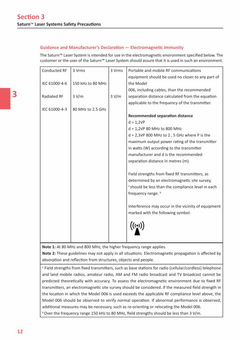
Conducted RF
IEC 61000-4-6
Radiated RF
IEC 61000-4-3
3 Vrms
150 kHz to 80 MHz
3 V/m
80 MHz to 2.5 GHz
3 Vrms
3 V/m
Portable and mobile RF communications equipment should be used no closer to any part of the Model006, including cables, than the recommended separation distance calculated from the equation applicable to the frequency of the transmitter.
Recommended separation distanced = 1,2√Pd = 1,2√P 80 MHz to 800 MHzd = 2,3√P 800 MHz to 2 , 5 GHz where P is the maximum output power rating of the transmitter in watts (W) according to the transmitter manufacturer and d is the recommended separation distance in metres (m).
Field strengths from fixed RF transmitters, as determined by an electromagnetic site survey, a should be less than the compliance level in each frequency range. b
Interference may occur in the vicinity of equipment marked with the following symbol:
Guidance and Manufacturer’s Declaration — Electromagnetic ImmunityThe Saturn™ Laser System is intended for use in the electromagnetic environment specified below. The customer or the user of the Saturn™ Laser System should assure that it is used in such an environment.
Note 1: At 80 MHz and 800 MHz, the higher frequency range applies.Note 2: These guidelines may not apply in all situations. Electromagnetic propagation is affected by absorption and reflection from structures, objects and people.a Field strengths from fixed transmitters, such as base stations for radio (cellular/cordless) telephone and land mobile radios, amateur radio, AM and FM radio broadcast and TV broadcast cannot be predicted theoretically with accuracy. To assess the electromagnetic environment due to fixed RF transmitters, an electromagnetic site survey should be considered. If the measured field strength in the location in which the Model 006 is used exceeds the applicable RF compliance level above, the Model 006 should be observed to verify normal operation. If abnormal performance is observed, additional measures may be necessary, such as re-orienting or relocating the Model 006. b Over the frequency range 150 kHz to 80 MHz, field strengths should be less than 3 V/m.
Section 3
3
Research Instruments Ltd
13
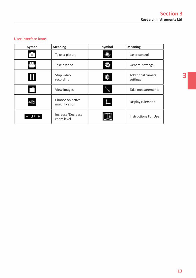
Symbol Meaning Symbol Meaning
Take a picture Laser control
Take a video General settings
Stop video recording
Additional camera settings
View images Take measurements
Choose objective magnification
Display rulers tool
Increase/Decrease zoom level
Instructions For Use
User Interface Icons
Section 3Saturn™ Laser Systems Safety Precautions
3
14
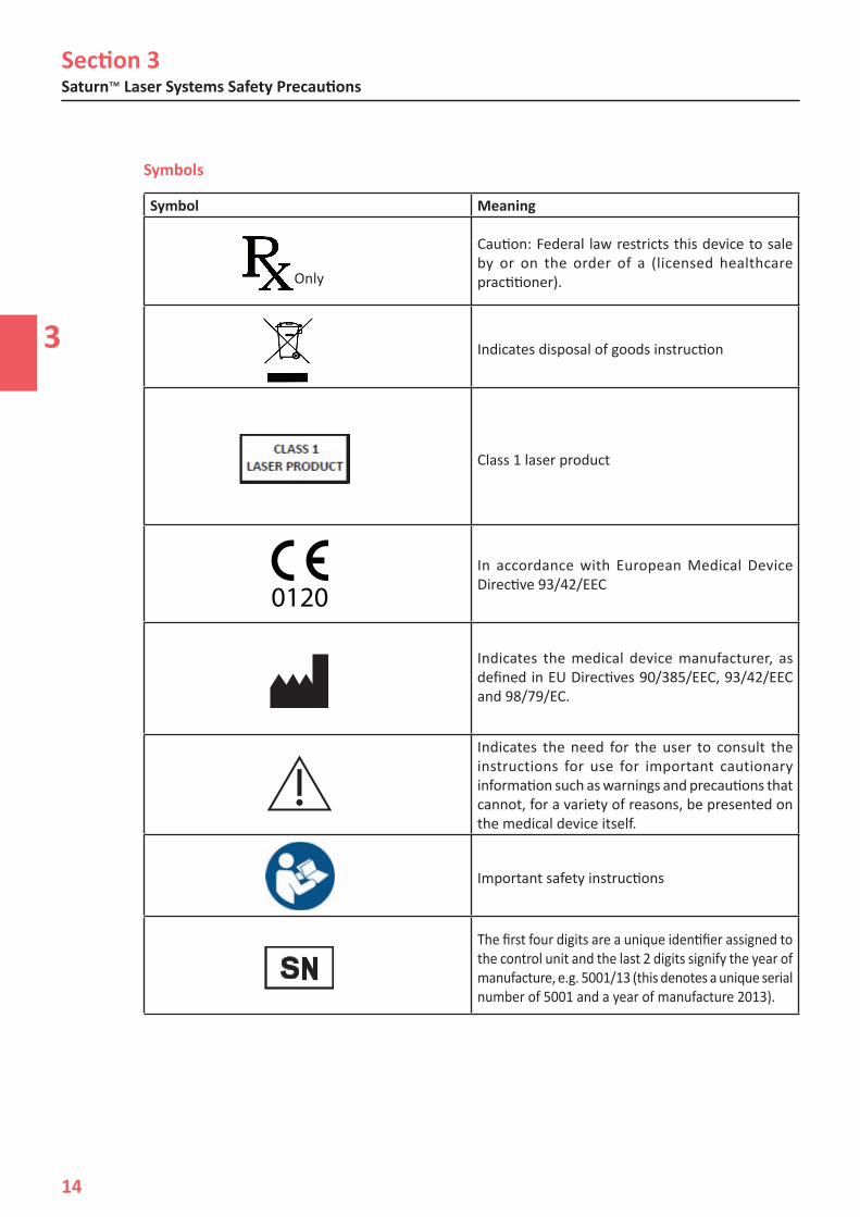
Symbols
Symbol Meaning
Caution: Federal law restricts this device to sale by or on the order of a (licensed healthcare practitioner).
Indicates disposal of goods instruction
Class 1 laser product
In accordance with European Medical Device Directive 93/42/EEC
Indicates the medical device manufacturer, as defined in EU Directives 90/385/EEC, 93/42/EEC and 98/79/EC.
Indicates the need for the user to consult the instructions for use for important cautionary information such as warnings and precautions that cannot, for a variety of reasons, be presented on the medical device itself.
Important safety instructions
The first four digits are a unique identifier assigned to the control unit and the last 2 digits signify the year of manufacture, e.g. 5001/13 (this denotes a unique serial number of 5001 and a year of manufacture 2013).
Only
0120
SN
4
Research Instruments Ltd
15
Section 4
SATURN™ LASER SYSTEMS PRODUCT OVERVIEW
Hardware Overview
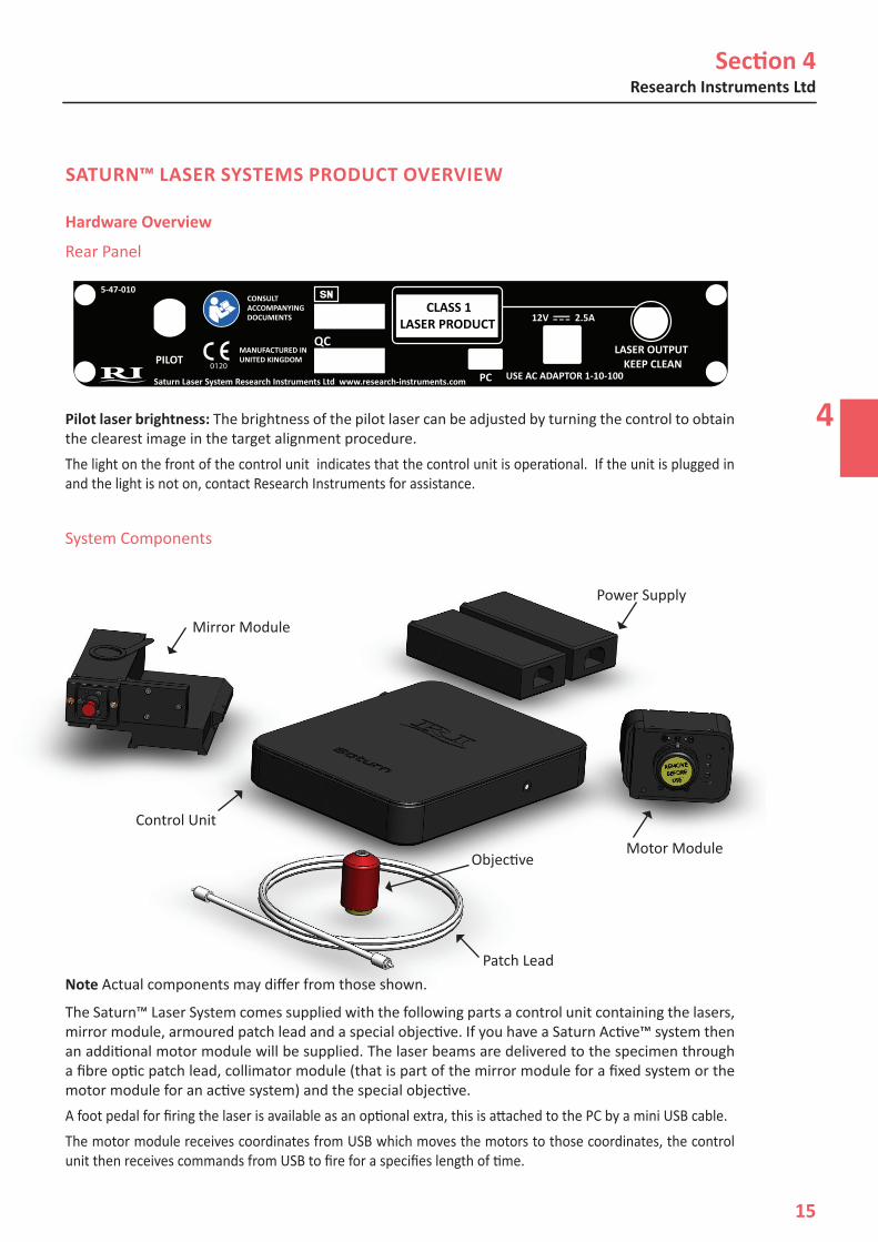
Rear Panel
Pilot laser brightness: The brightness of the pilot laser can be adjusted by turning the control to obtain the clearest image in the target alignment procedure.The light on the front of the control unit indicates that the control unit is operational. If the unit is plugged in and the light is not on, contact Research Instruments for assistance.
System Components
Note Actual components may differ from those shown.
The Saturn™ Laser System comes supplied with the following parts a control unit containing the lasers, mirror module, armoured patch lead and a special objective. If you have a Saturn Active™ system then an additional motor module will be supplied. The laser beams are delivered to the specimen through a fibre optic patch lead, collimator module (that is part of the mirror module for a fixed system or the motor module for an active system) and the special objective. A foot pedal for firing the laser is available as an optional extra, this is attached to the PC by a mini USB cable.The motor module receives coordinates from USB which moves the motors to those coordinates, the control unit then receives commands from USB to fire for a specifies length of time.
PCKEEP CLEAN
LASER OUTPUTPILOT
0120
MANUFACTURED INUNITED KINGDOM
PILOTPC
KEEP CLEANLASER OUTPUT
PART NUMBER: 2-47-012SATURN REAR PANEL ARTWORKECN: 1002ISSUE 2DRAWN: RGMDATE:15/10/12
QC
QC
CLASS 1LASER PRODUCT
5-47-010CONSULT ACCOMPANYING DOCUMENTS 12V 2.5A
USE AC ADAPTOR 1-10-100Saturn Laser System Research Instruments Ltd www.research-instruments.com
0120
MANUFACTURED INUNITED KINGDOM
CLASS 1LASER PRODUCT
5-47-010CONSULT ACCOMPANYING DOCUMENTS 12V 2.5A
USE AC ADAPTOR 1-10-100Saturn Laser System Research Instruments Ltd www.research-instruments.com
Mirror Module
Power Supply
Motor Module
Patch Lead
Objective
Control Unit

Section 4Saturn™ Laser Systems Product Overview
4
16
Packaging and Handling RequirementsNo special packaging or handling requirements
Part Number Description5-47-010 Control Unit with 1.5m Patch Lead5-47-100 Motor Module (Saturn™ Active)1-10-100 12V 2.5A Medical PSU (x2 for Saturn Active™)2-45-801 Laser Objective (red)
Saturn™ Laser System Component Part Numbers
Part Number Description5-46-163 Mirror module for IX53/73/83 left5-46-150 Mirror module for IX70 left5-46-160 Mirror module for IX70 right5-46-151 Mirror module for IX71 left5-46-152 Mirror module for IX71 right5-46-159 Mirror module for IMT25-46-135 Mirror module for TMD5-46-132 Mirror module for D3005-46-130 Mirror module for TE3005-46-140 Mirror module for TE2000 with Integra Ti™ 5-46-141 Mirror module for TE2000 without Integra Ti™ 5-46-142 Mirror module for Nikon Ti with Integra Ti™ 5-46-144 Mirror module for Nikon Ti with X-Y5-46-158 Mirror module for Ax405-46-110 Mirror module for Ax200/Observer5-46-120 Mirror module for DMIRB5-46-122 Mirror module for DMI3000B5-46-121 Mirror module for DMI4000B/6000B
Saturn™ Laser System Mirror Module Part Number and Descriptions
Saturn Active™ Mirror Modules
Section 4
4
Research Instruments Ltd
17
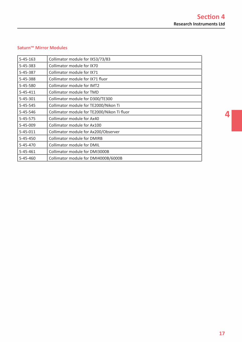
5-45-163 Collimator module for IX53/73/835-45-383 Collimator module for IX70 5-45-387 Collimator module for IX715-45-388 Collimator module for IX71 fluor5-45-580 Collimator module for IMT25-45-411 Collimator module for TMD5-45-301 Collimator module for D300/TE3005-45-545 Collimator module for TE2000/Nikon Ti5-45-546 Collimator module for TE2000/Nikon Ti fluor5-45-575 Collimator module for Ax405-45-009 Collimator module for Ax1005-45-011 Collimator module for Ax200/Observer5-45-450 Collimator module for DMIRB5-45-470 Collimator module for DMIL5-45-461 Collimator module for DMI3000B5-45-460 Collimator module for DMI4000B/6000B
Saturn™ Mirror Modules

Section 4Saturn™ Laser Systems Product Overview
4
18
Laser Specifications
Laser Specifications Ablation Laser Pilot LaserOutput wavelength 1480nm 650nmPower output from patch lead 400mW 130µW (max)Maximum pulse length 2.0ms None*Laser Safety Classification Class 1 Class 1
Magnification 40xN.A. 0.49Working distance 2.5mmParfocal distance 45mm (adaptor supplied for Nikon CFI60 systems)
Objective Specifications
Input 100-240VAC, 50-60Hz, 0.8-0.4AOutput Power (maximum) 30WVoltage 12VDCCurrent (maximum) 2.50AEarth Connection Mandatory 3-pin plug for earthing (grounding)
Electrical Specifications
Mains Adaptor for Control Unit and Motor Module
Control unit 220mmx180mmx34mm (8.6”x7.1”x1.3”) Weight 1.2Kg
Dimensions
USA Only
Compliance with the emissions requirements of CISPR 22 Class A requires the following warning: “This is a class A product. In a domestic environment this product may cause radio interference in which case the user may be required to take adequate measures.”
* IEC60825-1: 2008, US 21CFR 1040.10
Temperature 10°C (50°F) to 42°C (108°F)Humidity 15% to 85% RH (Non Condensing)
Operating Range
5
Research Instruments Ltd
19
Section 5
RI VIEWER™
IntroductionRI Viewer™ is the software that interacts with the Saturn™ and RI IMSI™ range of products from Research Instruments for use within an ART laboratory. Connected to a camera attached to a microscope, it provides on screen images of samples under the microscope. It can record video and store still images from the microscope in a PC’s file system. Supplied PC’s are IEC 60950-1 approved.
The operator should be positioned in such a place to easily access the microscope and also view the image on the PC monitor.
How to View Live ImagesA camera will need to be connected to the PC running RI Viewer™ and the drivers installed correctly to view live images within RI Viewer™. The dongle must also be fitted to a USB port.
RI Viewer™ software will automatically recognise both analogue and compatible digital camera devices connected to the PC. If there is only one camera device detected, it will show the live image for that device. If multiple camera devices are connected it will use the camera that was last selected from the Video Source drop down box.
If there are multiple cameras attached to the PC, you may select the device you want the live image to be viewed from. To do this select the camera from the dropdown list on the Settings panel. See Section 11 - How to Select Cameras.
How to Zoom & Pan the ImageThere are three ways to zoom into an area on the screen.
1. Place the mouse at a point on the screen and click and hold the right mouse button then release. This will zoom into the spot where the mouse is placed. To zoom out, click and hold the right mouse button.
2. Place the mouse at a point on the screen and use the scroll wheel on the mouse (if available).This will give the user control over how much digital zoom is given.
3. Using the tool bar at the bottom of the screen, click the + icon to zoom in incrementally. To zoom out by the same amount, click on the - icon on the tool bar. The magnifying glass icon will zoom in and out by the preset zoom.
Whilst using digital zoom, a thumbnail image of the screen will appear in the top left of the screen. At the top of this panel is the amount of magnification you are using. See Section 11 - How to Set the Preset Zoom. When zoomed out fully, this panel will not appear on the screen.
Zooming in and zooming out can also be achieved using the foot pedal. See Section 11 - How to Configure Foot Pedal/Keyboard.
Changing Camera Settings
Clicking on the tool bar will show a panel indicating the camera name and frames per second (fps). Clicking on Additional Settings will allow the user to adjust settings on the video source. Only settings available to the video source chosen will appear.
Section 5RI Viewer ™
5
20
How to Take a Picture
1. Click on the tool bar.
2. A camera icon will flash briefly in the centre of the screen to let the user know that an image has been taken.
Images are stored in a .bmp file format.
Images are named by default (date and time) yyyymmddhhmmss.bmp. For example, a picture taken on the 3rd of January 2012 at 10:35:02 would be named 20120103103502.bmp.
How to Record Video
1. Click on the tool bar.
2. Whilst video is being captured, a recording notification will flash in the top left corner of the screen.
3. Click on the tool bar and the recording notification will stop.
4. Each video recording can last for a maximum of one hour. This eliminates the problem of accidentally leaving the software recording with the possibility of rendering the computer unusable.
Recorded videos are stored in a .wmv file format
Recorded videos are named by default (date and time) yyyymmddhhmmss.wmv. For example, a video taken on the 3rd of January 2012 at 10:35:02 would be named 20120103103502.wmv.
How to Perform Measurements
1. Click on the tool bar.
2. Click on the screen to select a start point for the measurement.
3. Click on the screen a second time to select an end point for the measurement.
The ends of the line can be dragged to change the measurement.
Lines can be removed by clicking the cross in the context window.
Lines are shown during laser operation but cannot be dragged/created and no measurements will be displayed.
Lines and measurements are shown on an image when images are taken in line mode.
6
Research Instruments Ltd
21
Section 6
SATURN™ LASER SYSTEMS OPERATION
How to Configure the Laser for a New Procedure
1. Check objective calibration.
2. Check laser target alignment.
3. Check hole size calibration.
How to Check Objective Calibration
1. Click on the tool bar.
2. Click the Objective Calibration button to open the Objective Calibration panel.
3. Place an object of known dimensions (a stage micrometer is supplied with each system for this purpose) in the field of view.
4. Ensure that the objective selected in RI Viewer™ matches that being used on the microscope. See Section 11 – How to Select Objectives.
5. The stage micrometer supplied measures 100µm between the longer lines. For best accuracy, position each end point of the line at exactly the same relative position on the scale, for example at the right hand edge of each vertical line.
6. Drag the rulers to the point where the stage micrometer is going to be measured from and use the fine adjustment up and down until the ruler scale matches the stage micrometer.
How to Check Laser Target Alignment
1. Click on the toolbar. If the laser has not been aligned the Laser Target Alignment will start automatically.
2. Follow the on screen instructions.
Once Target Alignment has been completed, it can be accessed again by clicking Laser Settings, then Align Laser and finally clicking the Target Alignment button. This process is the same as the initial Target Alignment.
Section 6Saturn™ Laser Systems Operation
6
22
How to Check Hole Size CalibrationThe laser objective must be calibrated correctly for the Hole Size Indicator to work correctly.
The actual size of hole a laser produces may vary depending on the type of Petri dish and media, the characteristics of the embryo and other factors. For this reason, the Hole Size Indicator may be calibrated.
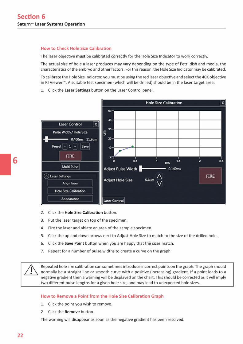
To calibrate the Hole Size Indicator, you must be using the red laser objective and select the 40X objective in RI Viewer™. A suitable test specimen (which will be drilled) should be in the laser target area.
1. Click the Laser Settings button on the Laser Control panel.
2. Click the Hole Size Calibration button.
3. Put the laser target on top of the specimen.
4. Fire the laser and ablate an area of the sample specimen.
5. Click the up and down arrows next to Adjust Hole Size to match to the size of the drilled hole.
6. Click the Save Point button when you are happy that the sizes match.
7. Repeat for a number of pulse widths to create a curve on the graph
Repeated hole size calibration can sometimes introduce incorrect points on the graph. The graph should normally be a straight line or smooth curve with a positive (increasing) gradient. If a point leads to a negative gradient then a warning will be displayed on the chart. This should be corrected as it will imply two different pulse lengths for a given hole size, and may lead to unexpected hole sizes.
How to Remove a Point from the Hole Size Calibration Graph1. Click the point you wish to remove.
2. Click the Remove button.
The warning will disappear as soon as the negative gradient has been resolved.
Section 6
6
Research Instruments Ltd
23
How to Fire the Laser (Single Pulse)1. Find the sample under the microscope using an objective with wide field of view (e.g. 4x
objective).
2. Hold the sample with a holding pipette at the bottom of the dish.
3. Switch to the Laser Objective and focus on the sample.
4. Click on the tool bar.
5.a Fixed System - position the sample such that the desired hole location is under the target.
5.b Active System - position the sample in the field of view. Click on the desired position of the hole.
6. Click the Fire button. The control unit will beep to confirm that the laser has fired.
In some installations, the field of view is larger than the range of movement of the laser. If the cursor is moved to a position on the screen where the laser cannot reach, the unreachable area will be highlighted. The target cannot be placed in this area.
How to Adjust Hole Size/Pulse Width1. Hold the left mouse button down and drag until the desired size is reached.
2. Click and drag the slider on the Laser Control panel.
3. Fine adjustment can be made using the up down keys.
Laser Target RI Viewer™ displays a laser target on the image. This indicates where the laser beam is focused, and thus where the hole will appear.
Note to use the laser system, the specimen must be viewed with the red laser objective.
The target will only be shown when the system is in laser mode.
The appearance and size of the laser target can be modified. The Target Appearance is displayed in the Laser Settings panel. You can change its appearance by adjusting the sliders. This is also where the size of the laser Exclusion Zone can be set.
Exclusion ZoneThe Exclusion Zone is used to show whether critical cells are close to the laser ablation area and may be affected by the heat. The default setting of 8μm is based on previous laboratory data*. This can be adjusted via the Target Appearance panel using the slider or input box. However, it is the responsibility of users to carry out appropriate trials to satisfy themselves of the safety of the chosen setting if the size is reduced from the default.
*K. Chatzimeletiou, K., Picton, H.M. & Handyside, A.H., 2001. Use of a non-contact, infrared laser for zone drilling of mouse embryos: assessment of immediate effects on blastomere viability. Reproductive Biomedicine Online, 2(3), p.178. Available at: http://www.ncbi.nih.gov/pubmed/12537793
Hole Size Indicator The circle that is displayed indicates the estimated size of the hole that will be created when the laser is fired. Actual hole sizes may vary due to natural differences between specimens.
The Hole Size Indicator can be turned on or off from the Target Appearance panel on the Laser Settings panel.

Section 6Saturn™ Laser Systems Operation
6
24
Preset Pulse LengthsThe preset values can be changed using RI Viewer™. Pulse lengths are limited to stay within Class 1 laser safety standards.
Choose the preset by clicking the + or - buttons. To change a preset, select the preset, set the desired value using the slider, and click the Save button.
Hole sizes can also be chosen by clicking on the screen and dragging a hole of the size you need. The pulse width will be calculated automatically to create the size of hole required.
How to Shut Down1. Close RI Viewer™ software.
2. Unplug the device from the power outlet.

7
Research Instruments Ltd
25
Section 7
ASSISTED HATCHING PROCEDURE
IntroductionThe aim of Laser Assisted Hatching (LAH) is to locally weaken the zona pellucida. The specimen is viewed along the optical axis and the laser creates a trench in the zona pellucida which extends above and
below the apparent hole.
To minimize the risk of damage to blastomeres, users should administer as few laser pulses as possible at the shortest pulse lengths possible to achieve prescribed zona drilling or thinning effects.
The optimum diameter of the hole is determined by the thickness and/or hardness of the zona. Larger holes are necessary in thicker zona. Smaller holes are preferable for thin zona. The hole may fully breach the zona, whilst some users prefer to ablate only a fraction of the zona thickness, but across a wider area. This process is commonly referred to as zona thinning.
Only a single opening should be made in the zona pellucida. Multiple openings or those that are too small may prevent embryo hatching or lead to abnormal development.
The site chosen for the hole should be a section of the zona pellucida where the adjacent perivitelline space is widest or next to an area of fragmentation. This will minimise possible damage due to heating of adjacent blastomeres. The Exclusion Zone display can help with this.
Note: Assisted Hatching is not recommended for routine use in all ART patients.
Summary1. Select the red laser objective on the microscope and check the Objective Calibration settings.
WARNING -The embryo may be damaged if objectives other than the red Saturn™ laser objective is used.
2. Check the target alignment before each LAH procedure. See Section 6 - How to Check Laser Target Alignment.
3. Check the temperature of the specimen (37°C).
4. Focus at the mid-plane of the embryo.
5. Position the embryo against the surface of the Petri dish using a micromanipulator and holding pipette to minimise embryo movement.
6. Choose a suitable location for the hole.
7. The first attempt to make a hole should be made with a short pulse. If the hole is too small, then use progressively longer pulses until the desired hole size is achieved.
Circle shows hole as viewed through
microscope

Section 7Assisted Hatching Procedure
7
26
Hole Size SelectionFor safe and effective treatment we recommend that pulses used are in the range 15 to 1000ms.
Pulses that are very short may be ineffective and pulses that are too long may damage the embryo. For this reason, a warning will appear on the Fire button when pulse width is 15ms or below and when the pulse width is greater or equal to 1000ms.
When the warnings are shown, the laser can still be fired, but an initial click on the Fire button is required to acknowledge the warning. If the pulse width is still in the warning range, then the button will go back to the warning state after the laser has fired.
Ablation Procedure Focus on the surface of a Petri dish and ensure that the target is correctly aligned to the pilot laser spot. Place the dish with the specimen on the microscope stage and hold the specimen on the bottom of the dish with a holding pipette. Check you are using the red Saturn™ laser objective. To ablate the zona, the focal plane must be at the mid section of the embryo. Refocus the microscope until the image of the zona is sharp.
Side view showing embryo on dish surface
Correct focus - specimen is sharply focussed.
Incorrect focus for drilling.
Focus here to ablate
Correct Incorrect X
Section 7
7
Research Instruments Ltd
27
Do not attempt to make a large hole with just one firing of the laser. Although this will not cause damage to the instruments, it could potentially damage the embryo due to the greater heating effect of the long pulse length.
For further information on the methodology of laser ablation, refer to the many published scientific papers on the subject, or seek advice from a practitioner who is experienced in the technique.
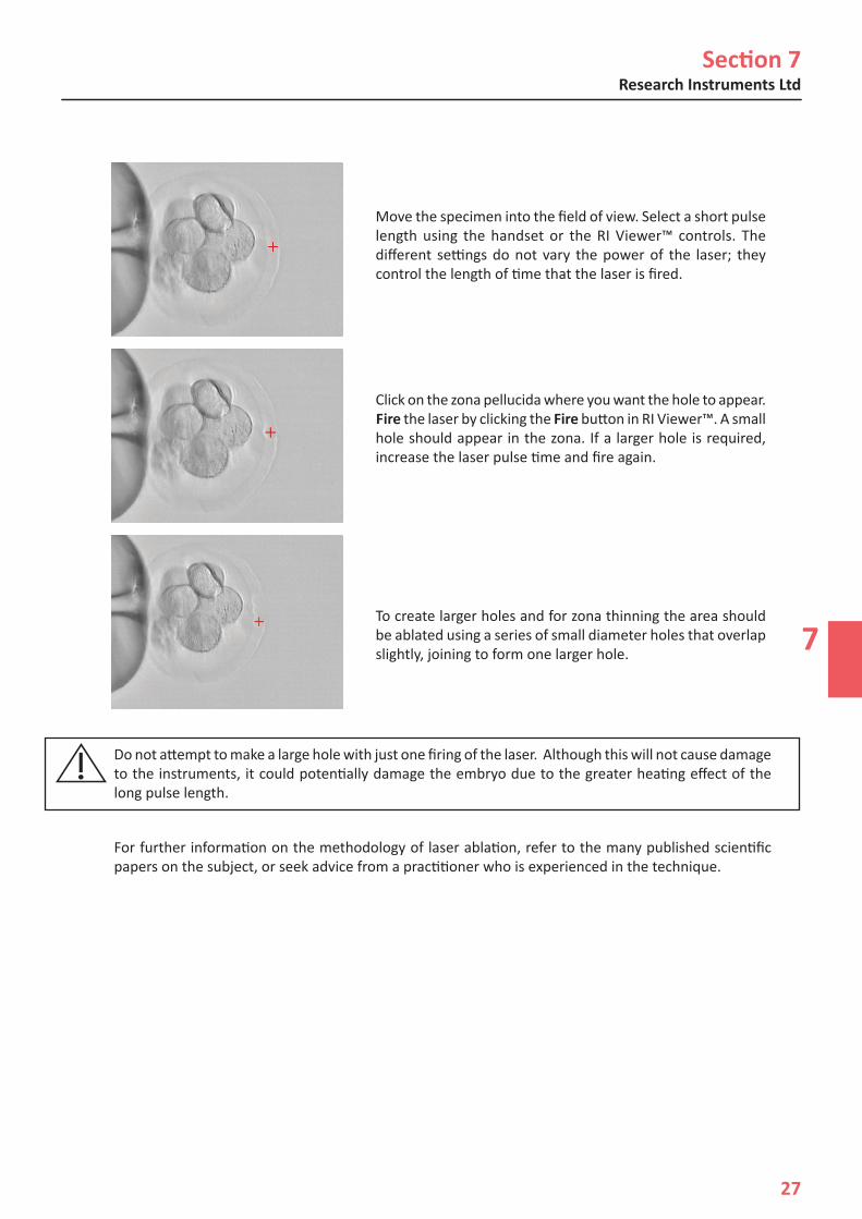
Move the specimen into the field of view. Select a short pulse length using the handset or the RI Viewer™ controls. The different settings do not vary the power of the laser; they control the length of time that the laser is fired.
Click on the zona pellucida where you want the hole to appear. Fire the laser by clicking the Fire button in RI Viewer™. A small hole should appear in the zona. If a larger hole is required, increase the laser pulse time and fire again.
To create larger holes and for zona thinning the area should be ablated using a series of small diameter holes that overlap slightly, joining to form one larger hole.
Saturn™ Laser Systems Additional Modes
8
28
Section 8
SATURN™ LASER SYSTEMS ADDITIONAL MODESUSA Clearance RegulationsIn the USA, Saturn™ Laser Systems are 510(k) cleared for Assisted Hatching only. The op-erations in this section are for investigational purposes only
How to Enable Biopsy Mode
1. Click on the tool bar.
2. Tick Enable Biopsy Mode (this option is available only with Saturn™ Active).
How to Enable Multi-Pulse Mode
1. Click on the tool bar.
2. Tick Enable Multi-Pulse Mode.
How to Fire the Laser (Biopsy Mode)
Biopsy Mode allows you to create a line of holes that will be drilled automatically. This mode will only be accessible if the Active component is installed.
1. Switch to the Laser Objective.
2. Focus on the sample.
3. Click on the tool bar.
4. Check the sample is just on the bottom of the dish.
5. From the Laser Control Panel, click Biopsy. You will be taken to the Laser Biopsy panel.
6. Click where the desired start point of the line. The line will follow your cursor.
7. Click the desired end point of the line. The holes to be drilled are overlain on the image.
8. The size and number of holes can be changed by moving the two sliders on the panel.
9. The ends of the line can be adjusted by dragging them.
10. A point in the middle can be dragged to create a curved line.
Press Start Firing to begin the firing procedure. The laser will then drill each hole in sequence. To interrupt this procedure press Stop.

Section 8
8
29
Research Instruments Ltd
How to Fire the Laser (Multi-Pulse Mode)The laser target cannot be moved during Multi-Pulse Mode.
1. Switch to the Laser Objective.
2. Focus on the sample.
3. Click on the tool bar.
4. Check the sample is just on the bottom of the dish.
5. From the Laser Control panel, click Multi-Pulse. You will be taken to the Multi-Pulse Laser panel.
6. Click on the screen to select the location to fire the laser (Active only).
7. Select the number of pulses per second.
8. Click Fire Multi-Pulse.
9. Move the sample with the holding pipette to ablate the required region. The control unit will beep continuously while the laser is firing.
10. Click Stop to complete the procedure. The laser will also stop firing automatically after 20 seconds.
Saturn ™ Laser Systems Troubleshooting
9
30
Section 9
SATURN™ LASER SYSTEMS TROUBLESHOOTING
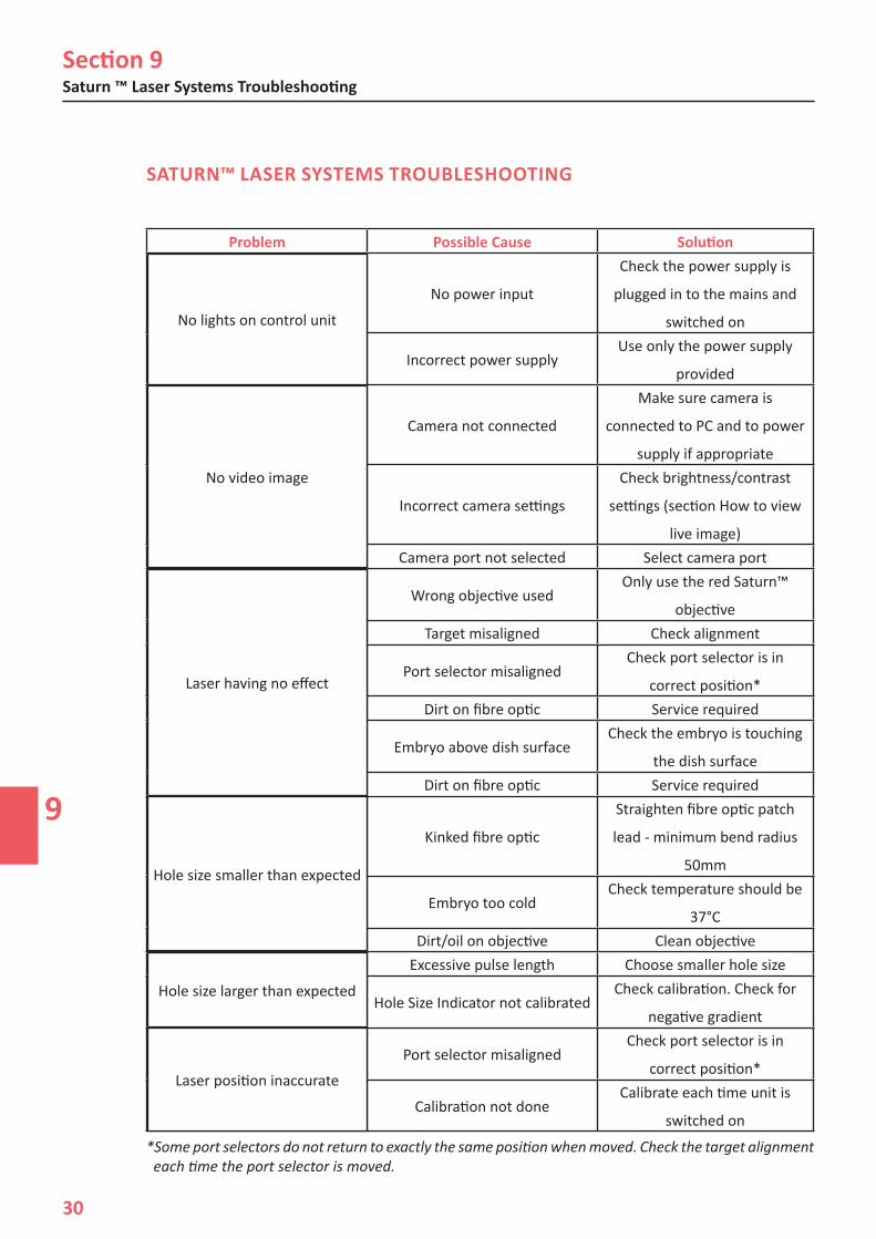
*Some port selectors do not return to exactly the same position when moved. Check the target alignment each time the port selector is moved.
Problem Possible Cause Solution
No lights on control unit No power input
Check the power supply is
plugged in to the mains and
switched on
Incorrect power supplyUse only the power supply
provided
No video image Camera not connected
Make sure camera is
connected to PC and to power
supply if appropriate
Incorrect camera settings
Check brightness/contrast
settings (section How to view
live image)Camera port not selected Select camera port
Laser having no effect Wrong objective usedOnly use the red Saturn™
objectiveTarget misaligned Check alignment
Port selector misalignedCheck port selector is in
correct position*Dirt on fibre optic Service required
Embryo above dish surfaceCheck the embryo is touching
the dish surfaceDirt on fibre optic Service required
Hole size smaller than expected Kinked fibre optic
Straighten fibre optic patch
lead - minimum bend radius
50mm
Embryo too coldCheck temperature should be
37°CDirt/oil on objective Clean objective
Hole size larger than expected Excessive pulse length Choose smaller hole size
Hole Size Indicator not calibratedCheck calibration. Check for
negative gradient
Laser position inaccurate Port selector misalignedCheck port selector is in
correct position*
Calibration not doneCalibrate each time unit is
switched on
No lights on control unit
No video image
Laser having no effect
Hole size smaller than expected
Hole size larger than expected
Laser position inaccurate
10
Research Instruments Ltd
31
Section 10
RI IMSI™
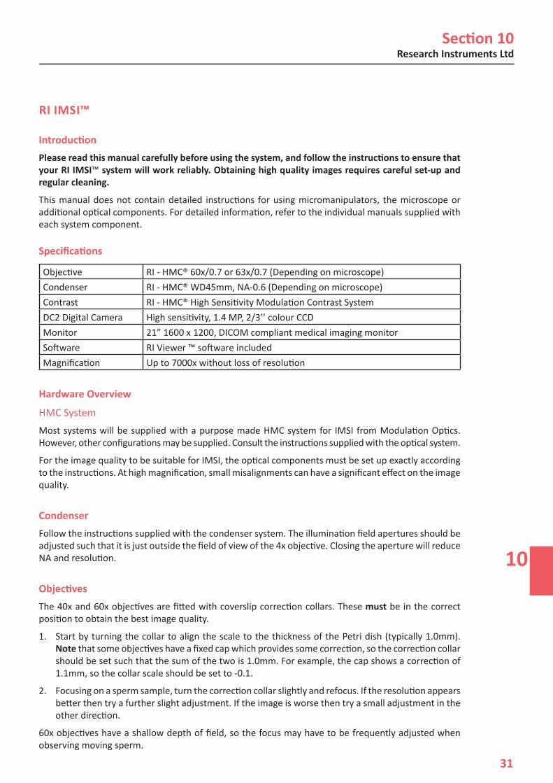
IntroductionPlease read this manual carefully before using the system, and follow the instructions to ensure that your RI IMSI™ system will work reliably. Obtaining high quality images requires careful set-up and regular cleaning.
This manual does not contain detailed instructions for using micromanipulators, the microscope or additional optical components. For detailed information, refer to the individual manuals supplied with each system component.
Specifications
Objective RI - HMC® 60x/0.7 or 63x/0.7 (Depending on microscope)Condenser RI - HMC® WD45mm, NA-0.6 (Depending on microscope)Contrast RI - HMC® High Sensitivity Modulation Contrast SystemDC2 Digital Camera High sensitivity, 1.4 MP, 2/3’’ colour CCDMonitor 21” 1600 x 1200, DICOM compliant medical imaging monitorSoftware RI Viewer ™ software includedMagnification Up to 7000x without loss of resolution
Hardware Overview
HMC System Most systems will be supplied with a purpose made HMC system for IMSI from Modulation Optics. However, other configurations may be supplied. Consult the instructions supplied with the optical system.
For the image quality to be suitable for IMSI, the optical components must be set up exactly according to the instructions. At high magnification, small misalignments can have a significant effect on the image quality.
CondenserFollow the instructions supplied with the condenser system. The illumination field apertures should be adjusted such that it is just outside the field of view of the 4x objective. Closing the aperture will reduce NA and resolution.
ObjectivesThe 40x and 60x objectives are fitted with coverslip correction collars. These must be in the correct position to obtain the best image quality.
1. Start by turning the collar to align the scale to the thickness of the Petri dish (typically 1.0mm). Note that some objectives have a fixed cap which provides some correction, so the correction collar should be set such that the sum of the two is 1.0mm. For example, the cap shows a correction of 1.1mm, so the collar scale should be set to -0.1.
2. Focusing on a sperm sample, turn the correction collar slightly and refocus. If the resolution appears better then try a further slight adjustment. If the image is worse then try a small adjustment in the other direction.
60x objectives have a shallow depth of field, so the focus may have to be frequently adjusted when observing moving sperm.

Section 10RI IMSI™
10
32
IMSI MonitorWe recommend a monitor designed for medical imaging, and that the PC is fitted with a separate PCI-E graphics card with DVI (Digital Video Interface) output and at least 256MB memory.
Place the monitor in a convenient position close to the microscope.
Adjust the height and angle of the monitor such that the operator can comfortably look towards the centre of the screen.
Monitor Settings (for Medical Monitor Supplied by RI) The M (Mode) button on the bottom edge of the monitor switches between display modes for different purposes. Confirm the chosen mode by pressing the l button. We suggest using DICOM mode for IMSI for the best image contrast and brightness. If the PC is used for other purposes (for example, office applications), the high brightness and colour temperature of the DICOM mode may be tiring. Change to Text mode for general computer use.
In Text mode the brightness and colour controls can be adjusted for comfortable viewing. We suggest setting Text mode to a brightness of 30% with a colour temperature of 6500K.
Brightness and colour cannot be manually adjusted in DICOM mode, as these settings are fixed to conform to the DICOM standard. See the monitor manual, supplied separately, for detailed instructions.
Sample Preparation
A solution of PVP is normally used to prepare a sperm drop in order to increase the viscosity of the medium and thus to slow the movement of the sperm. 60x objectives have a shallow depth of field. If sperm are allowed to move vertically within the drop, they will tend to move out of focus and may be hard to observe. It may be helpful to use a pipette to drag the edges of the drop outwards in a number of places to create shallow areas which will confine the sperm.
Observation1. Place the dish on the microscope stage.
2. Focus on the top surface of the dish using a low magnification objective. It may help to focus on the edge of the media droplet to begin with in order to focus on the surface.
3. Use the micromanipulator controls to place the tip of an injection pipette in the field of view.
4. Use progressively higher magnification and the x-y stage to locate an area of active sperm.
5. For examination of individual sperm morphology, select the 60x/63x objective and matching HMC position in the condenser turret.
6. Using the blue filter supplied with the HMC system will give colour images a blue cast, but will improve image resolution.
7. The software zoom feature can be used to increase the magnification. See Section 5 - RI Viewer™. This feature should be used sparingly, as high zoom levels will exceed the resolution available from the microscope optics. Use the micromanipulation system and a sperm injection micropipette to pick up the selected sperm and transfer them to the dish/droplet containing the oocytes to be fertilised.

Section 10
10
Research Instruments Ltd
33
Maintenance
General The microscope must be maintained to a high standard. Problems such as worn focus mechanisms, dirt on optics, etc. may result in reduced image quality.
It is essential that optical components are correctly adjusted to achieve the best image quality.
Cleanliness All exposed optical surfaces must be kept clean. Use an air blower followed by a dry lens cloth to remove dust particles. Oils from the skin, if a lens has been touched, and other marks can usually be removed with isopropyl alcohol wipes, followed by wiping with a dry lens cloth.
Monitor Calibration The monitors we supply will provide a high quality image with minimal set up. However, performance of any monitor will change slowly over time, and periodic calibration will ensure a high quality image for as long as possible.
Larger hospitals may have calibration facilities already in place to cover monitors used for X-ray imaging. Contact your IT/maintenance department for information.
Calibration involves measuring the screen output using a colorimeter. The measurements are stored by the graphics card and used to compensate for any slight errors. Note the colorimeter is specific for DICOM calibration on these monitors. General purpose colorimeters (e.g. Datacolor Spyder3) are not compatible.
Colorimeters can be supplied by RI, or a calibration service may be offered by your RI distributor or local representative of the monitor manufacturer. We suggest calibrating your monitor every twelve months.
Section 10RI IMSI™
10
34
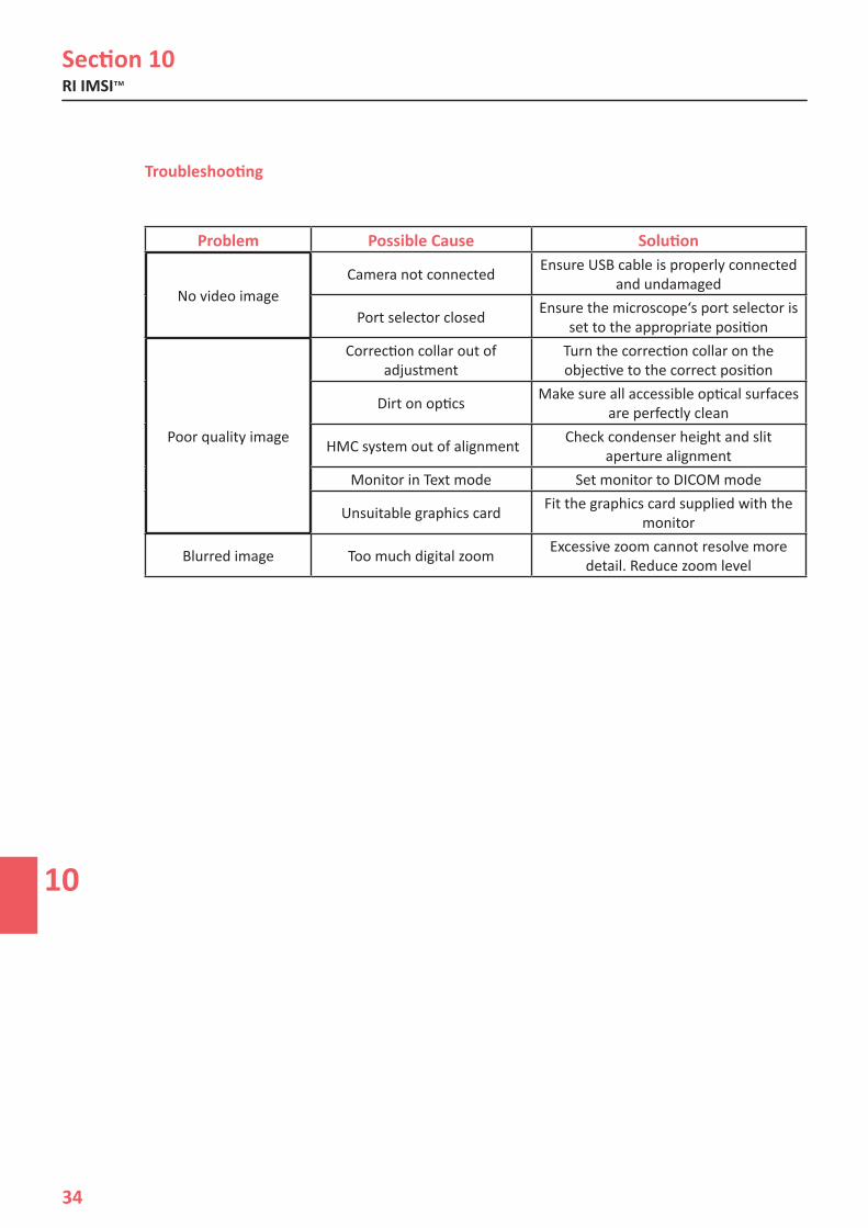
Troubleshooting
Problem Possible Cause Solution
No video image Camera not connected Ensure USB cable is properly connected and undamaged
Port selector closed Ensure the microscope‘s port selector is set to the appropriate position
Poor quality image Correction collar out of adjustment
Turn the correction collar on the objective to the correct position
Dirt on optics Make sure all accessible optical surfaces are perfectly clean
HMC system out of alignment Check condenser height and slit aperture alignment
Monitor in Text mode Set monitor to DICOM mode
Unsuitable graphics card Fit the graphics card supplied with the monitor
Blurred image Too much digital zoom Excessive zoom cannot resolve more detail. Reduce zoom level
No video image
Poor quality image

11
Research Instruments Ltd
35
Section 11
APPENDICES
How to Select Cameras
1. Click on the tool bar. The Video Source drop down box will have a list of camera names referring to the cameras connected to the PC.
2. Click on the drop down box to allow the selection of cameras. Clicking on the required camera in the list will change the live image to that of the selected camera.
Camera Flipping
1. Click on the tool bar.
2. Tick Flip Video Horizontal (for camera devices that support these options).
3. Tick Flip Video Vertical (for camera devices that support these options).
How to Set the Preset Zoom
1. Click on the tool bar.
2. Drag the Preset Zoom slider to the required zoom.
How to Configure the Foot Pedal/Keyboard
1. Click on the tool bar.
2. From the Settings panel click the Keyboard/Foot pedals Shortcuts.
3. Click the corresponding edit button to assign a shortcut.
4. Hold down the key or press the foot pedal to assign.
5. Click Save and Quit.
Once the shortcuts are set up, press the shortcut keys or the corresponding foot pedal to activate the command.
How to View Still and Recorded Images
1. Click on the tool bar.
From this location, the user can use their preferred image viewer to review, edit, email, rename and move the image file to a different location for further observations or the manipulation of any images that have been captured.

Section 11Appendices
11
36
How to Select Objectives
1. Click the magnification on the tool bar .
2. Click the required objective magnification.
How to Add Objectives
1. Click on the tool bar.
2. Click the Objective Calibration button.
3. Click New Objective. The magnification will be the same as the current magnification.
4. Click the required objective to edit Objective magnification and Fine Adjustment values.
How to Remove Objectives
1. Click on the tool bar.
2. Click the Objective Calibration button.
3. Click X next to an objective.
12
Research Instruments Ltd
37
Section 12
SATURN™ LASER SYSTEMS CARE AND MAINTENANCE
We recommend that a non PVC dust cover is placed over the microscope when not in use. Plasticisers commonly used in PVC are toxic to embryos.
The control unit case should be cleaned with a cloth moistened with isopropyl alcohol only. If any liquids are spilt over the control unit switch off immediately and remove the power connector. Clean the spill and ensure that the unit is completely dry before switching on. If it is suspected that any liquids have gone inside the case contact RI for advice before switching on.
Routine maintenance simply involves ensuring that all optical components are kept clean. The lens on the end of the Saturn™ objective should be cleaned occasionally by wiping gently with a dry lens cloth.
Every six months the collimator module should be removed and the dichroic mirror cleaned with a dry lens cloth. This should be done by RI or an appointed representative as the laser alignment must be checked and readjusted after removing the collimator module.
We recommend that the system undergoes a routine service at least every twelve months. This can normally be carried out by your distributor.
For further advice on microscope cleaning, please contact RI or your microscope supplier.
In the event that you have a problem with RI instruments, first look at the Troubleshooting section. If you require any further help, contact your distributor or RI’s service team direct. We will try to resolve the problem as quickly as possible.
Disposal of Goods
If any electronic component is no longer serviceable, it must be sent back to RI to be destroyed in an environmentally safe way. Do not dispose of with ‘normal’ waste.

Returns Procedure
13
38
Section 13
RETURNS PROCEDURE
1. Contact RI to obtain a Returned Materials Authorisation (RMA) number. Note goods will not be replaced or refunded without prior agreement and clearly stating the RMA number.
2. Pack the item carefully in its original packaging. RI will not accept responsibility for damage due to incorrect packaging. Replacement items or additional repairs will be invoiced.
3. Clearly label the consignment with the RMA number, mark the package “Urgent - Returned Items For Repair”, and ship to the address below. Goods should be insured for their full value during shipping.
Research Instruments Ltd Bickland Industrial Park, Falmouth, Cornwall, TR11 4TA, UK
Tel: +44 (0) 1326 372 753 Fax: +44 (0) 1326 378 783
E-mail: [email protected]
Website: www.research-instruments.com
Customer FeedbackThank you for purchasing an RI product. To help RI develop the best tools for ART, we rely on customer feedback. If you have any suggestions of how we can improve our products or the information we provide with it, please send them to [email protected]. Your feedback will help us develop the product and supporting materials to meet your future needs.
Thank you


Document 6-47-500UM(PV), Issue 5, 8th April 2013, ECN1076
RESEARCH INSTRUMENTS LTDBickland Industrial Park, Falmouth, Cornwall TR11 4TA, UKt: +44 (0) 1326 372 753 | f: +44 (0) 1326 378 783 |e: [email protected]