user manual - home - wahlberg motion design-dmx...
TRANSCRIPT

WWW.WAHLBERG.DK AXEL GRUHNS VEJ 3 TELEPHONE: +45 86 18 14 20 8270 HØJBJERG EMAIL: [email protected] DENMARK
Winch 10 Cable Item No 212 / 213
User Manual
Winch 10 Cable 4 m (212) Winch 10 Cable 10 m (213)

213.805.018 2 Date: 2017-10-24
Safety Information
The following symbols are used to identify important safety information on the product an in this manual:
This product is for professional use only. It is not for household use. This product presents risks for severe injury or death due to fire hazards, electric shock, and falls. Read this manual before installing, powering or servicing the winch; follow the safety precautions listed below and observe all warnings in this manual and printed on the winch. If you have questions about how to operate the winch safely, please contact you Wahlberg Motion Design supplier or Wahlberg Motion Design. PROTECTION FROM ELECTRIC SHOCK − Disconnect the winch from AC power before removing or installing any cover or
part and not when in use. − Always ground (earth) the winch electrically. − Use only a source of AC power that complies with local building and electrical
codes and has both overload and ground-fault (earth-fault) protection. − Before using the winch, check that all power distribution equipment and cables are
in perfect condition and rated for the current requirements of all connected devices.h
− Power input throughput cables must be rated 20 A minimum, have three conductors 1.5 mm2 (AWG16) minimum conductor size and an outer cable diameter of 5-15 mm (0.2-0.6 inch). Cables must be hard usage type (SJT or equivalent) and heat-resistant to 90°C (194°F) minimum. In the EU the cables must be <HAR> or equivalent.
− Use only Neutrik powerCON TRUE1 NAC3FX-W cable connectors to connect to power input sockets. Use only Neutrik powerCON TRUE1 NAC3MX-W cable connectors to connect to power throughput sockets.
− Assembly power supply cables following the instructions in this manual only (see page 15).

213.805.018 3 Date: 2017-10-24
− Isolate the winch from power immediately if the power plug or any seal, cover, cable, or other component is damaged, defective, deformed, wet, or showing signs of overheating. Do not reapply power until repairs have been completed.
− Do not expose the winch to rain or moisture. − Refer any service operation not described in this manual to a qualified technician.
PROTECTION FROM BURNS AND FIRE − Do not operate the winch if the ambient temperature (Ta) exceeds 40°C (104°F). − The exterior of the winch becomes warm during use. Avoid contact by persons and
materials. Allow the winch to cool for at least 10 minutes before handling. − Do not modify the winch in any way not described in this manual. − Install only genuine Wahlberg parts.
PROTECTION FROM INJURY − Fasten the winch securely to a fixed surface, rig, or structure when in use. The
winch is not portable when installed. − Ensure that any supporting structure and/or hardware can hold at least 10 times
the weight of all the devices including their load. − If suspending from a rigging structure, fasten the winch using the supplied
Manfrotto slim coupler and M12 bolt, nut, and washers supplied with the winch according to the manual, see page 12.
− Always install the winch as described in this manual. If the winch is installed in a location where it may cause injury or damage if it falls, install as described in page 12.
− If possible, allow enough clearance beneath the winch so it cannot cause any danger to personnel beneath it.
− Check that all external cobblers and rigging hardware are securely fastened. − Block access below the work area and from a stable platform whenever installing,
servicing or moving the winch. − Do not operate the winch with missing or damaged covers, shields, or lifting cable. − Do not use the winch over the head of people − Do not use the winch to lift people or animals. − Only use the winch to lift static loads.
Before each use − Check that the winch is safely and correctly installed/mounted. − Inspect the entire length of the lifting cable for bends, damage,
wear, broken or cut cord, and abuse. − Inspect the cable lock and thimble for damage, wear, corrosion,
or abuse. − Secure that the load is safely attached and weighs max 10 kg. − Check all limit switches. − Check the slack detection device
Warning! Do not use the winch if any damage or error is found! Inspection points
Broken wire
Intact wire

213.805.018 4 Date: 2017-10-24
Disposing of this product Wahlberg Motion Design products are supplied in compliance with Directive 2002/96/EC of the European Parliament and of the Council of the European Union on WEEE (Waste Electrical and Electronic Equipment), as amended by Directive 2003/108/EC, where applicable.
Help preserve the environment! Ensure that this product is recycled at the end of its life. Your supplier can give details of local arrangements for the disposal of Wahlberg Motion Design products.

213.805.018 5 Date: 2017-10-24
Index SAFETY INFORMATION 2 INDEX 3 TECHNICAL SPECIFICATIONS 6 DRAWINGS 7 INTRODUCTION 9
PACKAGE CONTENT ......................................................................................... 9 DESCRIPTION ................................................................................................ 9 SAFETY FUNCTIONS ........................................................................................ 10 AREA OF USE ............................................................................................... 10 USING FOR THE FIRST TIME ................................................................................. 11 TRANSPORT ................................................................................................ 11
PHYSICAL INSTALLATION 12 FASTENING THE WINCH TO A FLAT SURFACE ................................................................ 12 MOUNTING THE WINCH ON A TRUSS ........................................................................ 12 MOUNTING THE LOAD ...................................................................................... 14
AC POWER 15 POWER CABLES AND POWER PLUG .......................................................................... 15 INSTALLING A POWER INPUT CONNECTOR ON A POWER CABLE ............................................... 15
DATA LINK 16 TIPS FOR RELIABLE DATA TRANSMISSION .................................................................... 16 CONNECTING THE DMX .................................................................................... 16
LIFTING CABLE POWER AND DATA LINK 17 LIFTING CABLE CONNECTION PLUG ......................................................................... 17 CONNECTING THE POWER CABLE ........................................................................... 17 CONNECTING THE DATA LINK ............................................................................... 17
SET UP 18 BLOCK DIAGRAM ........................................................................................... 18 COUNTERBALANCE – SLACK CABLE ......................................................................... 18 CONNECTIONS ............................................................................................. 18 EMERGENCY STOP .......................................................................................... 20 MODE SETTING ............................................................................................ 20 DMX ADDRESS SETTING .................................................................................. 22 MANUAL RESET ............................................................................................. 24 POSITIONING ............................................................................................... 24 RE-CALIBRATING OVERLOAD ................................................................................ 25 SYNCHRONIZED MOVEMENTS OF MULTIPLE WINCHES ......................................................... 25 CONTROLLING THE SOFT TOP AND BOTTOM LIMITS ....................................................... 26
SERVICE AND MAINTENANCE 27 PARTS ..................................................................................................... 27 MAINTENANCE PLAN ........................................................................................ 28 CHECKLIST ................................................................................................. 28 ON-SITE SERVICE ........................................................................................... 29 LIFE OF THE LIFTING CABLE ................................................................................ 30 LIFTING CABLE DEFECT ..................................................................................... 31 LIFTING CABLE DISCARD CRITERIA .......................................................................... 33 CHANGING LIFTING CABLE .................................................................................. 34 APPLYING WIRE ............................................................................................ 39 POWER DEFECT ............................................................................................ 40
APPENDIX 1 41 APPENDIX 2 42 APPENDIX 3 43 APPENDIX 4 45 APPENDIX 5 46 WINCH 10 CABLE - CHEAT SHEET 47

213.805.018 6 Date: 2017-10-24
Technical specifications Model: Winch 10 cable (4m 212 / 10m 213) Item no.: 212 / 213 Dimensions (Without mounting clamp): 212 (4m) 224 × 275 × 148 mm / 9.5 × 10.8 × 5.8 in (L×H×W) 213 (10m) 224 × 395 × 148 mm / 9.5 × 15. × 5.8 in (L×H×W) Power supply: 230 V AC 50 Hz (optional 120V/60Hz). Power consumption: Max 120 Watt. Power inlet/outlet: Neutrik powerCON TRUE1 NAC3PX (F/M) DMX control signal: DMX 512 1990 + DMX512A / 7 channels used. DMX connection: 5 pole XLR, In & link Lifting height: 212 (4m) 3.8 m (13 ft.) 213 (10m) 9.8 m (33 ft.) Lifting capacity: 10 kg (22 lb) Lifting speed: Variable, 5-30 cm/s (2-11.8 in/s) Capability of overload test: Yes, at 125% of maximum load. Minimum load: 2.5 kg (5.5 lb) Snap hook: 8 mm (5/16 in) galvanised steel Noise emission: ~50 dB (max measured noise at 1 m/3.3 ft.) Weight: 212 (4m) 6.1 kg (13.4 lb) 213 (10m) 8.8 kg (19.4 lb) Mounting clamp: 212 (4m) 1× Slim eye coupler 50 mm (2 in) 213 (10m) 2× Slim eye coupler 50 mm (2 in) Motor: 24 V DC, 28.9 Watt, IP30 Lifting Cable Specifications: Lifting cable: 5 mm (13/64 in) Special Kevlar cable Minimum breaking load (cable): 100 kg (0.99 kN / 222 lb) Cable safety factor: minimum 10 Cable fleet: 212 (4m) 90 mm / 3.54 in 213 (10m) 220 mm / 8.7 in Maximum cable current: Red / Black Max. 5A, 2×0.75mm2 (AWG18) White / Yellow Max. 1A, 2×0.25mm2 (AWG24) Inlet Neutrik SpeakON NL4MP Maximum expected lifting cable lifetime:
− At 2.5 kg (5.5 lb) load Up to 250,000 cycles running up and down. − At 5.0 kg (11.0 lb) load Up to 100,000 cycles running up and down. − At 10 kg (22.0 lb) load Up to 5,000 cycles running up and down.

213.805.018 7 Date: 2017-10-24
Drawings 212 (4 m) More detailed drawings and from more angles can be found in Appendix 1 on page 41

213.805.018 8 Date: 2017-10-24
213 (10 m) More detailed drawings and from more angles can be found in Appendix 2 on page 41.

213.805.018 9 Date: 2017-10-24
Introduction Thank you for selecting the winch 10, a DMX controlled winch from Wahlberg Motion Design. Before using the winch for the first time, please read this manual carefully. Failure in handling can cause injury of persons and/or damage the winch.
Package content 1× Winch 10 cable (212 or 213) 1×/2× Manfrotto Slim coupler 1×/2× Mounting bolt, nut, and washers (M12) for slim coupler mounting 1× Neutrik PowerCon NAC3FX-W female plug for power cable 1× Neutrik SpeakON 4 NL4FC plug for lifting cable attachment 1× 8 mm snap hook 1x User manual 1x Cheat sheet
Description Winch 10 cable is a small winch for stage use, mainly for use in theatres, shows and concerts. It lifts lamps and other electronical devices in and out of the stage sphere at a maximum load of 10 kg up and down. Lifting height is 3.8 meters (model 212) or 10 meters (model 213), and the lifting speed is from 5cm/s to 30 cm/s. The winch is controlled by the standard DMX controlling signal, so a normal lighting desk can be used to control the movement, programmed as normal light. For a low number of winches, a standard lighting desk can be used, but when many winches are used, more advanced desks should be used to maintain easy control of the units. The lifting cable is a Kevlar reinforced cable with 4 conductors that enables both power and data connections to the lifting object. The connection for the cable has its own connector, so the user can connect any kind of signal desired. The Winch 10 cable uses 7 channels of the DMX-line, and they control the position, speed, limits, and reset functions. The winch has an advanced internal positioning system with 16 bit, used for finding the position desired by the operator. With a 16 bit positioning channel (ch1 and ch2) the operator set the desired position, and the winch will run to this position, with the speed applied on the speed channel (ch3). With channel 4 and 5 it is possible to set the soft TOP and BOTTOM limits of the winch, adjusting its span of motion. Channel 6 and 7 is used for resetting the winch, when powering up. Multiple winches are easily daisy chained with power in-out and DMX in-Out, allowing to create advanced and dynamic movements with 100’s of winches working together in the same installation.

213.805.018 10 Date: 2017-10-24
Safety functions The control system ensures that the motor only is powered when: • The control signal is reliable. • The position and speed control is on. • The motor position is calculated after which a PID regulator calculates the motor
speed and distance. • No overload.
Winch 10 cable should only be operated by an experienced DMX-controlled-lighting-desk-operator. The lighting desk has to be programmed according to the manual, so the winch will stop when the speed is put to 0%. It is also possible for the user to stop the winch by disconnecting it from the main. After power failure the start position of the winch needs to be reset before the winch can function again. Manual operation of the winch is only intended for mounting, service, and tests.
Area of use For indoor use only!
Caution! To reduce the risk of electric shock or injury: use indoors only
Caution! To reduce the risk of electric shock, do not expose to rain: store indoors!
The winch is intended for indoor use only. It is designed for lifting and lowering material at the weight and speed stated in "Technical specifications" on page 6. Any other use of the winch may result in a risk of injury of persons or equipment damage. Exceeding the load rating may cause failure of the equipment. Use only approved rigging connectors to secure the load to the lifting cable and do not wrap the lifting cable around the load as this will damage the lifting cable and result in a risk of injury of persons or equipment damage. Do not modify the winch. For any modification of your winch, contact Wahlberg. It is the customer's sole responsibility to comply with any relevant local laws, regulatory requirements, and restrictions, concerning the use of the winch.

213.805.018 11 Date: 2017-10-24
Using for the first time Important! The Winch 10 cable must be protected from environmental factors such as physical shocks and vibration during storage. Warning! Read “Safety Information” on page 2 before installing, powering, operating, or servicing the winch. Before applying power to the winch: − Check the Wahlberg Motion Design website at www.wahlberg.dk for the most
recent documentation and technical information about the winch 10 cable. Wahlberg user manual revisions are identified by the revision number in the bottom of each page.
− Carefully review the “Safety Instructions” on page 2. − Check that the local AC mains power source is within the winch power voltage and
frequency ranges. − See “Power cables and power plug” on page 2. Install a Neutrik powerCON TRUE1
NAC3FX-W power input connector on a suitable power cable. If using the power from a mains power outlet, install a suitable power plug on the power cable.
Transport Important! The Winch 10 cable must be protected from environmental factors such as physical shocks and vibration during transportation.
Before transport, it is important to roll the lifting cable of the winch up till the hard TOP limit so a maximum of 5 cm (1.9 inch) remains out of the winch. If the lifting cable is loose it may jump off the lifting cable drum during transport and cause damage to the winch. Use only the original packaging, flight case, or pallet frame for protecting the winch during transport. Contact Wahlberg for enquiries regarding flight cases or pallet frames.

213.805.018 12 Date: 2017-10-24
Physical installation Warning! The winch must be either fastened to a flat surface such as a roof, or clamped to a truss or similar structure in such a way that the lifting cable exit points downwards. Do not apply power to the winch if it is not securely fastened. Warning! If fastening the winch to a flat surface, the supporting surface must be hard and flat. Fasten the winch securely. Warning! If mounting the winch on a truss, use only the supplied rigging clamp and M12 bolt. The clamp must be screwed into the central hole in the winch’s mounting bracket using the supplied M12 washers and M12 locking-nut.
Fastening the winch to a flat surface The Winch 10 cable can be fastened to flat surface such as a roof. Check that the surface can support at least 10 times the weight of all winches and equipment to be installed on it.
Mounting the winch on a truss The Winch 10 cable can be clamped to a truss or similar rigging structure.
To clamp a Winch 10 to a truss:
1. Check that the rigging clamp is undamaged and that the rigging structure can support at least 10 times the combined weight of all winches and equipment to be installed on it.
2. Use the supplied rigging clamp or contact Wahlberg Motion Design for a replacement.
3. Fasten the clamp to the winch with the supplied M12 bolt, nut, and washers in the hole in the mounting clamp of the winch.
4. Block access under the work area. Working from a stable platform, hang the winch on the truss with the lifting cable downwards. Tighten the rigging clamp.
213.805.018 13 Date: 2017-10-24
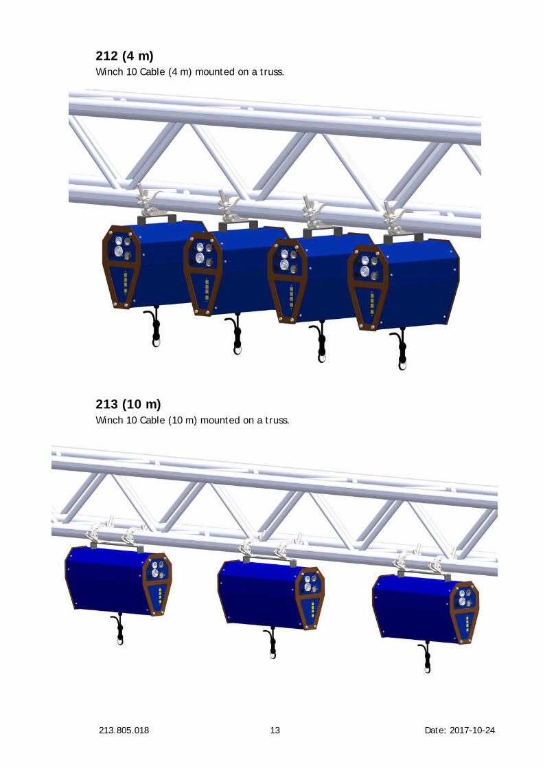
212 (4 m) Winch 10 Cable (4 m) mounted on a truss.
213 (10 m) Winch 10 Cable (10 m) mounted on a truss.

213.805.018 14 Date: 2017-10-24
Mounting the load The load can be mounted using the supplied loading hook or any other hooks designed for lifting. Ensure that the loading hook has a minimum breaking load of at least 100 kg.
Attention! The load must be mounted on the cable in a way to insure that the load never can run into the winch.

213.805.018 15 Date: 2017-10-24
AC power Warning! Read “Safety Information” on page 2 before connecting the winch to AC mains power. Warning! For protection from electric shock, the winch must be grounded (earthed). The power distribution circuit must be equipped with a fuse or circuit breaker and ground-fault (earth-fault) protection. Warning! Socket outlets or external power switches used to supply the winch with power must be located near the winch and easily accessible so that the winch can easily be disconnected from power.
Warning! Check that the voltage range specified on the winch’s serial number label matches the local AC mains power voltage before applying power to the winch. Do not apply AC mains power to the winch at any other voltage than that specified on the winch’s serial number label.
Power cables and power plug The Winch 10 cable requires a power input cable with a Neutrik powerCON TRUE1 NAC3FX-W cable connector for AC mains power input. The cable must meet the requirements listed under “Protection from electric shock” on page 2. Wahlberg Motion Design can supply the PowerCON input connector without a cable. If you install a power plug on the power cable, install a grounding-type (earthed) plug that is rated 20 A. Follow the plug manufacturer’s instructions. Table 1 shows standard wire color-coding schemes and some possible pin identification schemes; if pins are not clearly identified, or if you have any doubts about proper installation, consult a qualified electrician.
Table 1 - Colour guide
Wire Colour Conductor Symbol Screw (US)
Brown Live L Yellow or brass
Blue Neutral N Silver
Yellow/green Ground (earth) or
Green
Installing a power input connector on a power cable
To install a Neutrik powerCON TRUE1 NAC3FX-W input connector on a power Cable, follow the original Neutrik instructions in Appendix 3.

213.805.018 16 Date: 2017-10-24
Data link A DMX 512 data link is required in order to control the winch via DMX. The Winch 10 cable has 5-pin XLR connectors for DMX data input and output. The pin-out on all connectors is pin 1 = shield, pin 2 = (-), and pin 3 = (+). Pins 4 and 5 in the 5-pin XLR connectors are not used in the Winch 10 cable but are available for possible additional data signals as required by the DMX512-A standard. The Winch 10 cable is subject to the common limit of 32 devices per daisy-chained link. Note that if independent control of a winch is required, it must have its own DMX channels. Winches that are required to behave identically can share the same DMX channels. To add more winches or groups of winches when the above limit is reached, add a DMX universe and another daisy-chained link.
Tips for reliable data transmission Use shielded twisted-pair cable designed for RS-485 devices: standard microphone cable cannot transmit control data reliably over long runs. AWG24 cable is suitable for runs up to 100 meters (328 ft.). Never split a DMX line without using an opto-isolated RS-485 splitter/amplifier. Terminate the link by installing a termination plug in the output socket of the last winch. The termination plug, which is a male XLR plug with a 120 Ohm, 0.25 Watt resistor soldered between pins 2 and 3, “soaks up” the control signal so it does not reflect and cause interference. If a splitter is used, terminate each branch of the link.
Connecting the DMX To connect the Winch 10 cable to data:
1. Connect the DMX data output from the DMX controller to the Winch 10 cable’s male 5-pin XLR DMX input connector (DMX 512 IN).
2. Connect the DMX output of the winch to the DMX input of the next winch and continue connecting winches output to input (DMX 512 OUT).
3. Terminate the last winch on the link with a 120 Ohm resistor.
The DMX lamp is the green led, next to the DMX-selectors. − Glows constantly: DMX connection is correct. − Flashes: DMX signal is missing or wrongly connected.

213.805.018 17 Date: 2017-10-24
Lifting cable power and data link Warning! Read “Safety Information” on page 3 before connecting AC mains power to the lifting cable. Warning! Socket outlets or external power switches used to supply the lifting cable attachment with power must be located near the winch and easily accessible so that the lifting cable attachment can easily be disconnected from power. Warning! Check that the voltage range specified for the lifting cable matches the attached power voltage before applying power to the lifting cable. Do not apply power to the lifting cable at any other voltage than that specified in this manual.
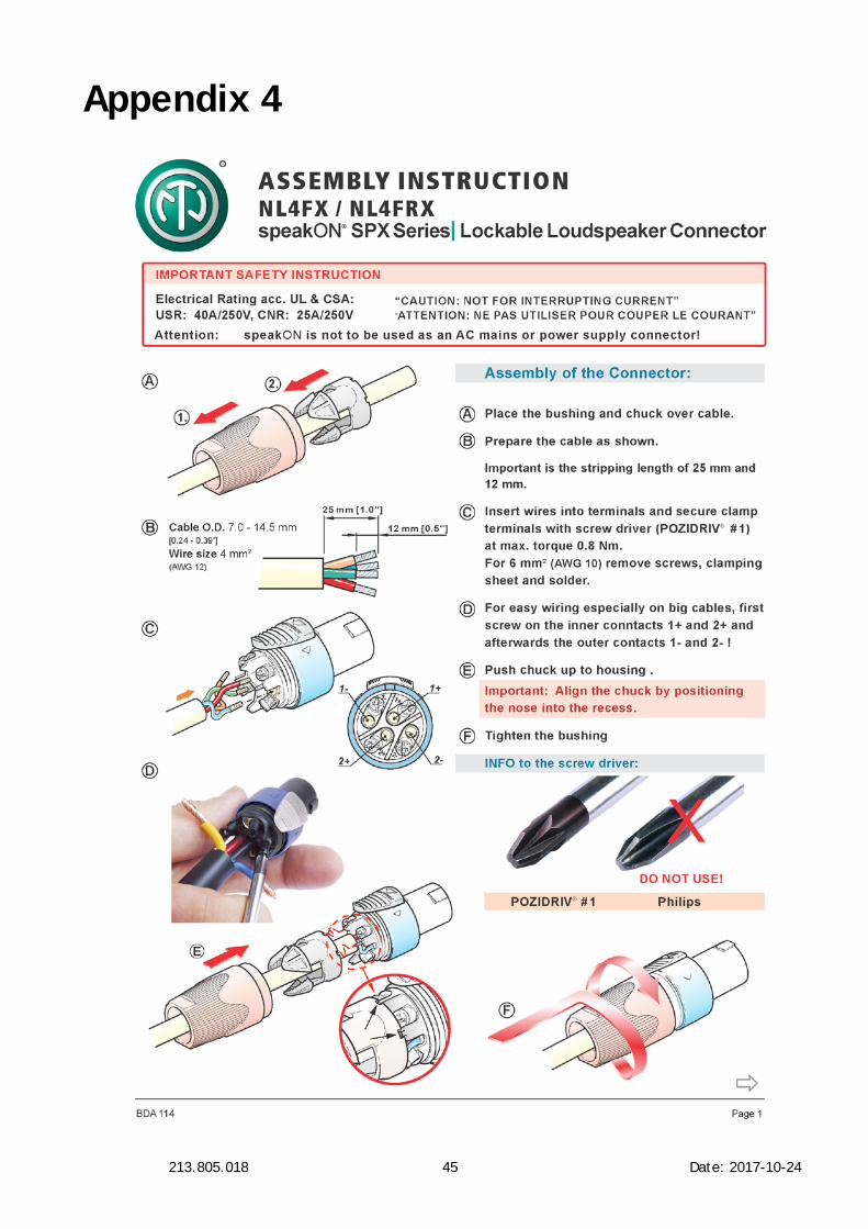
Lifting cable connection plug The Winch 10 cable requires a power and data input through a Neutrik speakON NL4FX cable connector. The cable for connecting the speakON plug on the winch for the lifting cable power and data, must meet the requirements listed under “Protection from electric shock” on page 2. The lifting cable has four conductors; two for power and two for data.
Connecting the power cable Refer to the section “AC power” on page 15 for installation of the power connection.
Connecting the data link Refer to the section “Data link” on page 16 for installation of the data connection. To install a Neutrik speakON NL4FX cable connector, follow the original Neutrik instructions in Appendix 4.

213.805.018 18 Date: 2017-10-24
Set up Warning! Read “Safety Information” on page 2 before installing, powering, operating, or servicing the Winch 10 cable. Warning! Before running the winch, it is important to put a counterbalance on the lifting cable. This is necessary, as the slack detection switch otherwise will be activated and stop the winch. Warning! Only experienced DMX users should operate the winch. Contact Wahlberg for further information and education on DMX protocol.
Block diagram A block diagram of the control system can be found in Appendix 5.
Counterbalance – Slack Cable To ensure proper and tight winding of the lifting cable on the drum, the winch is equipped with a slack detections device, that stops the motor if the lifting cable is loose or cable slack detected. Therefore, when the winch is mounted, ensure that the winch has some kind of counterweight attached to the lifting cable hook, if not, the winch will not work properly, and will not lower down.
Connections The winch has 4 plugs. At the top there are 2 DMX plugs, one for connecting DMX in and one for daisy chaining the DMX connection to other devices. Below there is a power connection plug for POWER in, and one plug that can be used to daisy chain the power connection between multiple devices. Below those plugs is the fuse and a voltage selector. It is important that the voltage selector has been set to the appropriate voltage before power is applied to the winch.

213.805.018 19 Date: 2017-10-24
On the back side there is a SpeakON inlet for the cable connection. The cable has 4 loose wires near the cable end that can be terminated in the most appropriate way for the application intended.
213.805.018 20 Date: 2017-10-24
Emergency stop There is no dedicated emergency stop for this winch. The winch is controlled from a lightning desk, where it should always be set up with a button that sets the speed of the winch in operation to 0%. Normally lighting desks have a “blackout” button that sets all signals to 0% and this will also cause the winch to stop.
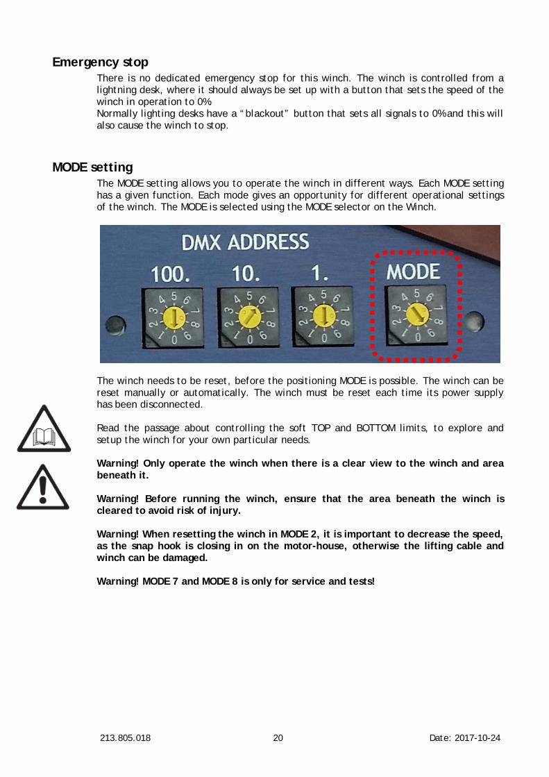
MODE setting The MODE setting allows you to operate the winch in different ways. Each MODE setting has a given function. Each mode gives an opportunity for different operational settings of the winch. The MODE is selected using the MODE selector on the Winch.
The winch needs to be reset, before the positioning MODE is possible. The winch can be reset manually or automatically. The winch must be reset each time its power supply has been disconnected. Read the passage about controlling the soft TOP and BOTTOM limits, to explore and setup the winch for your own particular needs. Warning! Only operate the winch when there is a clear view to the winch and area beneath it. Warning! Before running the winch, ensure that the area beneath the winch is cleared to avoid risk of injury. Warning! When resetting the winch in MODE 2, it is important to decrease the speed, as the snap hook is closing in on the motor-house, otherwise the lifting cable and winch can be damaged.
Warning! MODE 7 and MODE 8 is only for service and tests!

213.805.018 21 Date: 2017-10-24
MODE Function Description Note 0 Neutral Mode The motor is not powered and the winch does not move.
1 Positioning AUTO reset
The winch resets automatically and thereby also sets the soft TOP limit automatically.
The winch runs up until the snap hook reaches the motor-house and stops. Because of this, the soft TOP limit in this MODE will always be at the motor-house.
To start the automatic resetting, speed must be added on the speed-channel (DMX channel 3).
When the winch has been reset, it is possible to use it in positioning mode.
2 Positioning MANUAL reset
The winch is manually reset on the DMX channels 6 or 7.
The soft TOP limit is, because of this, also set manually, which makes it possible to decide the position of the soft TOP limit.
It is highly recommended to set the top position at the motor-house. When the winch has been reset, it is possible to use it in positioning mode.
Warning! When resetting in MODE 2, decrease the speed, as the load is closing in on the winch, otherwise the lifting cable and winch can be damaged
3,4,5,6 No function assigned The winch stops
7 Manual run up (no DMX needed)
The winch runs up with the speed set on the DMX-selectors.
This function can be used as a test-function or in association with on- and off-applying of lifting cable.
E.g. Set the winch to MODE 7 and the DMX address to 100, for a slow movement, or set the DMX address to 500 for fast movement.
Warning! Only for service and tests!
8 Manual run up (no DMX needed)
The winch runs down with the speed set on the DMX-selectors.
This function can be used as a test-function or in association with on- and off-applying of lifting cable.
E.g. Set the winch to MODE 8 and the DMX address to 100, for a slow movement, or set the DMX address to 500 for fast movement.
Warning! Only for service and tests!
9 Re-calibrating overload
See page 25 Warning! Only for service and tests!
Table 2 - Overview of MODE functions

213.805.018 22 Date: 2017-10-24
DMX ADDRESS setting The DMX address, also known as the start channel, is the first channel used to receive instructions from the controller. For independent control, each winch must be assigned its own control channels. The DMX address is configured using the three DMX ADDRESS selectors on the winch. The selected DMX address states from which channels, on the lighting desk, the winch is controlled. The DMX address can be selected from 1 – 505. The Winch 10 cable uses 7 DMX channels.
DMX channel Function Description 1 Position rough This channel controls the position of the winch, with the speed (DMX channel 3).
This rough position works together with the fine position (DMX channel 2).
The rough position and the fine position are multiplied in to a 16 bit channel. The rough position is the MSB.
2 Position fine This channel controls the position of the winch, with the speed set on DMX channel 3.
This fine position works together with the rough position (DMX channel 1).
The fine position and the rough position are multiplied in to a 16 bit channel. The fine position is the LSB.
3 Speed This channel controls the speed and defines the maximum speed of the winch.
The winch runs with the set max speed, but slows down as closing in on the wanted position.
This channel also works as a main brake; the motor does not run unless the channel is set above 0%.
The speed-channel can also be used to make soft and slow movements or fast and sudden movements.

213.805.018 23 Date: 2017-10-24
4 Set max travel top This channel controls the maximum top travelling height of the winch. When the winch has been reset and the soft TOP limit thereby has been declared, it is possible, by adjusting this channel, to change how high the winch may run in proportion to the soft TOP limit. So the top travelling height for the winch is changed.
0% declares the maximal top travelling height, which means it runs all the way up to the soft TOP limit.
100% declares the minimal top travelling, which means it is as far from the soft TOP limit as possible.
By adjusting this channel the positioning run from 0 - 100% will be within this new parameter. The top travelling height can be changed as needed, without resetting the winch’s top position.
5 Set soft BOTTOM limit
The channel controls the maximum bottom travelling height of the winch. When the winch has been reset and the soft TOP limit thereby has been declared, it is possible, by adjusting this channel, to change how low the winch may run in proportion to the soft BOTTOM limit. So the bottom travelling height for the winch is changed.
0% declares the maximal bottom travelling height, which means it, runs all the way down to the soft BOTTOM limit.
100% declares the minimal bottom travelling, which means it is as far from the reset bottom position as possible.
By adjusting this channel the positioning run from 0 - 100% will be within this new parameter. The bottom travelling height can be changed as needed, without resetting the winch soft TOP limit.
6 Find soft TOP limit, moving UP
The channel is used to manually finding the soft TOP limit. The channel controls the speed from 0-100%.
The winch starts to run up when channel 6 is set above 0%. When the winch reaches the wanted soft TOP limit, the speed must be set to 0 %, so that the motor stops.
The soft TOP limit of the winch is then set to the position the winch stopped in.
The soft TOP limit should always be near by the motor-house. See more details in the passage controlling the soft TOP and BOTTOM limits.
Attention! The positioning run in MODE 2 works only, when the winch has been reset.
7 Moving down The winch starts to run down when the speed is set above 0 %. This can be used to manually move the winch down without using positioning.
This does not change the top position.
Table 3 - Overview of DMX addresses
213.805.018 24 Date: 2017-10-24
Manual reset When the winch is ready, the first thing to do is to reset it. This is done manually in MODE 2 on DMX channel 6. Reset example: − The DMX channel 6 is set to 30% → the winch starts to roll up the lifting cable. − When the snap hook approaches the motor house reduce the speed by reducing the
DMX channel 6 input. High speed can damage the winch and lifting cable. − Let it run until the snap hook, at the end of the lifting cable, reaches the motor-
house. The winch is now reset and the soft TOP limit is at the build-in motor-house top (10 cm below). If you want to have a lower soft TOP limit, simply just set the DMX channel 6 to 0% and the place where the winch stops is your new soft TOP limit. The soft BOTTOM limit is set in the same way, just using DMX channel 7 instead.
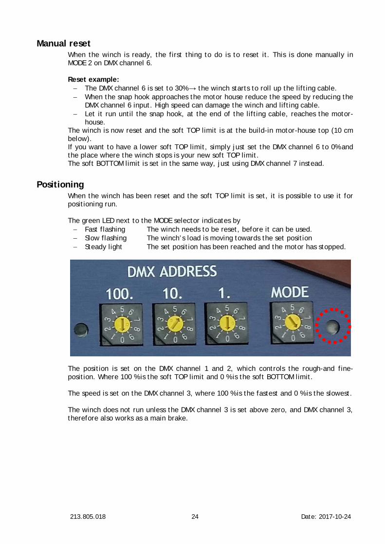
Positioning When the winch has been reset and the soft TOP limit is set, it is possible to use it for positioning run. The green LED next to the MODE selector indicates by − Fast flashing The winch needs to be reset, before it can be used. − Slow flashing The winch’s load is moving towards the set position − Steady light The set position has been reached and the motor has stopped.
The position is set on the DMX channel 1 and 2, which controls the rough-and fine-position. Where 100 % is the soft TOP limit and 0 % is the soft BOTTOM limit. The speed is set on the DMX channel 3, where 100 % is the fastest and 0 % is the slowest. The winch does not run unless the DMX channel 3 is set above zero, and DMX channel 3, therefore also works as a main brake.

213.805.018 25 Date: 2017-10-24
Re-calibrating overload Warning! Re-calibrating the overload affects safety mechanisms of the winch. Violation of the maximum overload can cause a dangerous situation with risk of serious injury or death. The winch is set to enter overload mode if the winch is loaded with more than the nominal load. The overload is a safety feature to ensure that the winch cannot lift more than what is safe. The overload detection is based on the motor current which is affected by the effectiveness of the gear. As the gear’s effectiveness changes with usage, the overload may need re-calibrating. It is therefore essential to control that the overload is correct at regular inspections. The overload can be re-calibrated to lower values as follows:
1. Ensure at least 1.5 m clearance below the winch 2. Load the winch with the desired overload threshold weight + 10% (max 11kg total) 3. Set the DMX channels to 999
Attention! When setting the mode to 9, the winch will start moving 4. Then set mode to 9
The winch will now run down a number of times. When the winch has moved back to the soft TOP limit the overload has been re-calibrated. Ensure to change the DMX channel and MODE away from 999 and 9 after re-calibration.
Synchronized movements of multiple winches If several winches are installed to perform synchronized movements the best result is achieved by using a fading 16 bit position. The winches have a slight deviation in performance of the motors, so some motors have a slightly higher maximum speed than others. This difference in speed can be solved by running the winches with fading positions, like when fading conventional light over time, the position of the winch should be faded from one position to another over a certain amount of time. In that way the winches will follow the fade-curve, and multiple winches can follow the same fade curve. When fading the positions:
1. The speed channel should be a set to 100 to gain the highest possible speed. 2. The position channel should be assigned as a 16 bit channel with MSB and LSB. 3. The speed of the fade needs to be slower than the maximum speed, so the
motors have speed enough to follow the fade-curve. If the fade of the positions is too fast, the winches will move at the maximum speed, and you will see the difference in the motor speed. If the fade is to slow the winches will move – stop – move – stop, when the position changes, thus giving a discontinuous movement.

213.805.018 26 Date: 2017-10-24
Controlling the soft TOP and BOTTOM limits The soft TOP limit needs to be reset automatically or manually, before the winch is able to use for positioning run. To get the most precise run, fit for your own needs, it is possible to regulate the soft TOP and BOTTOM limits. The soft TOP limit is reset manually by the DMX channels 6. When the soft TOP limit is being reset it should always be set near by the motor-house. This is important to notice because the winch has a pre-set soft BOTTOM limit, which is always set 10 meters from the pre-set soft TOP limit. Therefore, if the soft TOP limit is set far from the motor-house and the soft BOTTOM limit is not adjusted, the winch will still run 10m. (33ft.) down and eventually run out of lifting cable. This will activate the slack detection and the winch will not go any further down. To avoid that the winch runs out of lifting cable, the max travel to the top and the bottom should instead be adjusted on DMX channels 4 and 5. Attention! If the two spectrums beneath overlap, the soft TOP limit overrules the soft BOTTOM limit and the winch will move down to that position, but will be unable to be moved with normal positioning, because the operating spectrum has been reduced to 0.
Table 4 - DMX Channel 4 & 5 relative positions
DMX ch. 4 Distance from the soft TOP limit DMX ch. 5 Distance from the
soft BOTTOM limit 0 % 0 m (0 ft) 0 % 0 m (0 ft) 10 % 0.3 m (1.0 ft) 10 % 1 m (3.3 ft) 20 % 0.6 m (2.0 ft) 20 % 2 m (6.6 ft) 30 % 0.9 m (3.0 ft) 30 % 3 m (9.8 ft) 40 % 1.2 m (4.0 ft) 40 % 4 m (13.1 ft) 50 % 1.5 m (5.0 ft) 50 % 5 m (16.4 ft) 60 % 1.8 m (6.0 ft) 60 % 6 m (19.7 ft) 70 % 2.1 m (7.0 ft) 70 % 7 m (23.0 ft) 80 % 2.4 m (8.0 ft) 80 % 8 m (26.2 ft) 90 % 2.7 m (9.0 ft) 90 % 9 m (29.5 ft) 100 % 3.0 m (10.0 ft) 100 % 10 m (32.8 ft)

213.805.018 27 Date: 2017-10-24
Service and maintenance Warning! Read “Safety Information” on page 2 before servicing the Winch 10 cable. Warning! Disconnect the Winch from AC mains power and allow cooling down for at least 10 minutes before handling. Warning! Refer any service operation not described in this user manual to a qualified service technician. Attention! Interval of inspections should be determined according to the frequency of use and the working scenario of the winch. Attention! If the lifting cable runs in an angel the performance degrades and it causes the lifting cable to wear down faster; and shortens the life time of the lifting cable significantly! Lifting cable damage caused by mounting the winch in an angle is not covered by the product warranty. Attention! Signs of malfunction or poor operation should always lead to an inspection of the winch, and the winch should be taken out of operation until the error is eliminated.
Parts Only parts ordered at or approved by Wahlberg should be used in the winch to ensure product function and stability. Contact Wahlberg to inquire about spare parts.
213.805.018 28 Date: 2017-10-24
Maintenance plan The results of all the regular inspections are to be documented and kept available at the company. The written result of the last inspection must be kept available at the site of operation, e.g. by an inspection sticker on the winch showing the date of the inspection, the basis of the inspection and the name of the inspector. Before every use and weekly Every time when rigging the winch, before running the winch – and at least every week when the winch is in use:
− Check that the winch is safely and correctly installed/mounted − Check that the winch’s load and LEDs are visible from the operating station − Check the entire length of the lifting cable for bends, crushed areas, broken or
cut cord, and other damages. − Check all safety devices (slack detection, hard TOP limit). − Check that the lifting cable is winded neatly on the drum. − Check that the load is securely mounted
Monthly At regular intervals – but at least every month when the winch is in use:
− Check the mounting clamp and loading hook for damages and proper fastening. − Change damaged parts according to this manual. − Control that the overload is correct. − Check that the lifting cable is running smoothly on the drum. If the insulation has
a dry or rough surface, you can lubricate it with a tiny amount of silicone grease. − Check the secure fastening of the attached lamp or electronic equipment − Check the electric fastening of electronic equipment. − Check all conductors in the lifting cable rope for conductivity
Yearly The winch has to be inspected by a specialist every 12 months. Every 48 months The winch should be inspected by an authorised expert every 48 months.
Checklist Use the checklist accordingly; before each use, each month etc.
Check Type Result
Installed / mounted correct Inspection
Load and LEDs visible for the operator Inspection
Entire lifting cable length OK Inspection
Lifting cable conductivity Functional test
Slack detection Functional test
Hard TOP limit Functional test
Overload Functional test
Cable is winded neatly around the drum Inspection
lifting cable ‘wire lock’ Inspection
lifting cable thimble Inspection
Load mounted safely Inspection

213.805.018 29 Date: 2017-10-24
On-site service On-site service and maintenance can be provided by the Wahlberg Motion Design, giving owners access to Wahlberg Motion Design’s expertise and product knowledge in a partnership that will ensure the highest level of performance throughout the product’s lifetime. Please contact Wahlberg Motion Design for details.

213.805.018 30 Date: 2017-10-24
Life of the lifting cable It is Wahlberg policy to apply the strictest possible calibration procedures and use the best quality materials available to ensure optimum performance and the longest possible component lifetimes. However, lifting cables are subject to wear and tear over the life of the product, resulting in special attention to the state of the lifting cable. The extent of wear and tear depends heavily on operating conditions and environment, so it is impossible to specify precisely whether and to what extent the lifting cable performance will be affected. The expected lifetime of the lifting cable depends on the load and travel length as well as duty cycle (refer to Table 5).
Table 5 - Expected lifting cable life time at 0° angle
Load Max. expected number of cycles (up and down) 2.5 kg 250,000 5.0 kg 100,000 10 kg 5,000
The lifting cable should be inspected long before these numbers are reached and checked for damages, and replaced if necessary
Figure 1: Illustration of the Winch 10 cable mounted in different angles

213.805.018 31 Date: 2017-10-24
Lifting cable defect If the lifting cable in any way gets damaged, stuck, or have problems winding on and off, the lifting cable and lifting cable roll-up needs to be inspected. This can be done the following way:
1. Disconnect the power and the lifting cable power. 2. Remove the six 3mm hexagonal socket screws, on one of the middle plates on
the winch. 3. Take off the loose middle plate, to look into the winch. See the picture below. 4. If the lifting cable is not tight around the wire-wheel, or it is bungled up inside,
the lifting cable needs to be unravelled. This is done by manually unravelling and loosening the lifting cable and pulling it out of the winch. It might be necessary to remove both middle plates on the winch for better access to the cable.
5. Roll out the entire length of the cable to check it properly for any damage. 6. Set the MODE to 0 and connect the power to the winch (NOT the cable).
Warning! Be careful not to touch the power supply inside the winch as it is no longer shielded by the middle plates.
7. When the power is connected, use the manual run. 8. Set the DMX start address to zero (000) 9. Set the MODE to manual down (MODE 8) 10. Set the speed on the DMX address - Suggested address is 100, which is a slow
speed. Make sure that the cable does not get dirty when rolled out of the winch. Warning! Only use slow speed (DMX < 200). One can accidentally move the BCD to 9 instead of 0 leading to very high speed. Slack detection is active, so releasing the cable will activate the slack and stop the motor! Warning! Be careful not to get your fingers, hair, clothes etc. caught in the drum as it turns. This can damage both you and the winch.
11. When the motor starts and the cable is rolling out, it is important to hold on to
the cable to prevent it from tangling around the drum. 12. When the cable is rolled off all the way, set the speed (DMX start address) to
zero (000) and disconnect the power.

213.805.018 32 Date: 2017-10-24
13. Check the entire cable for damages. If the cable is okay it must be rolled on again.
Attention! If the cable is damaged, it has to be replaced. Read the passage “Change lifting cable” on page 34, to learn how to replace the lifting cable.
Roll cable back on the winch:
14. Set the MODE to 0 and connect the power to the winch (NOT the cable). 15. Set the MODE to manual up (MODE 7) 16. Set the speed on the DMX address to 100.
Warning! Only use slow speed (DMX < 200). One can accidentally move the BCD to 9 instead of 0 leading to very high speed. The slack detection is NOT active, so releasing the cable will NOT stop the motor! The hard TOP limit is active, so holding on to the wire until it activates the hard TOP limit will stop the motor! Warning! Be careful not to get your fingers or likewise caught in the drum as it turns. This can damage both you and the winch.
17. When the motor starts and the cable is rolling on, it is important to hold on to the cable and thereby make a counterbalance, so it rolls on tightly around the drum.
18. While rolling up the cable, apply a tiny amount of silicone grease to the cable. (Just put a tiny amount of silicone grease on your fingers, and apply it to the cable while rolling up. Do not overdo it). This will make the cable roll smoothly and with less friction on the drum.
19. Make sure not to bend or damage the loose cable as it rolls on. 20. When the cable is rolled on all the way, set the speed (DMX start address) to zero
(000) and disconnect the power. 21. When the cable has been applied to the winch again it is a good idea, to run it
up and down a couple of times, before assembling the winch. Remember always to make a counterbalance in the cable when running with the winch, as this is often the reason why the cable gets loose and tangled up in the first place.

213.805.018 33 Date: 2017-10-24
Lifting cable discard criteria When the lifting cable is exposed the following guidelines can be used to control whether the lifting cable must be discarded. The following serves as guidelines and if any of the discard criteria are reached, the winch must immediately be taken out of service, and the lifting cable replaced, before using the winch again. The lifting cable should be discarded when:
− When there is evidence of considerable plastic wear or surface embrittlement.
− When the diameter of the lifting cable has suddenly reduced.
− When there is any evidence of internal fragmentation in the lifting cable. This can be recognized by the lack of conductivity of the electrical conductors in the lifting cable.
− When the lifting cable has been subjected to mechanical damage, crushing, kink, bends, etc.
− When the lifting cable has been subjected to a high temperature or heat due to fire.
− Where the electrical conductors within the lifting cable has been exposed to more power than recommended.
− When the lifting cable has been subjected to severe shock load or over load due to an accident with the winch.

213.805.018 34 Date: 2017-10-24
Changing lifting cable If the lifting cable has any damaged, the winch must not be used before the lifting cable has been replaced (See section “Parts” on page 27). This can be done following the instructions below, or by Wahlberg Motion Design. Please contact Wahlberg for information regarding approved spare parts and questions for the procedure. Procedure for changing the lifting cable:
1. Roll off the lifting cable: a. Set the winch to MODE 8 (Manual roll down) b. Pull down in the wire to de-activate the slack detection. c. Continue pulling until all the lifting cable has been rolled off the winch d. Cut off the old lifting cable.
2. Disconnect the power. 3. Remove the six 3mm hexagonal socket screws, on each of the middle plates on the
winch. 4. Take off the two loose middle plates, to access the wire mount
5. Remove the end frame and plate by removing the four 4mm hexagonal socket screws.
6. Remove the two hexagonal spacers and the four bolts holding the Power supply plate.
7. Take the PVC tube out of the Power supply plate.

213.805.018 35 Date: 2017-10-24
8. Remove the two bolts and nuts holding the mounting plate and the Power supply plate together.
9. Carefully lift off the Power supply plate and tilt it. Ensure that none of the wires and plugs are damaged during this operation.
10. Lift off the cable drum and remove the old lifting cable.
11. Remove the four screws holding the print, and the two screws holding the cable clip. 12. Remove the soldering of the wire on the print.

213.805.018 36 Date: 2017-10-24
13. Put the new cable through the ‘top stop’. Then through the angled hole in the cable drum. Attention! Use only original Wahlberg spare parts.
14. Solder the wires in the cable on to the print in the same order as they were before. 15. Place the print so the cable can be secured under the cable clip, and so the holes in
the print fit with the holes in the drum.
16. Ensure that the ‘loose’ metal plate (with a hexagonal, four small holes and four large holes) is positioned correctly. Otherwise the print will not be mounted flat on the drum.
17. Mount the cable clip. Fasten it slightly. 18. Mount the print using the four screws. Fasten slightly. 19. Mount the cable drum, and ensure that the ‘top stop’ and slack detection is mounted
correctly.

213.805.018 37 Date: 2017-10-24
20. Mount the Power supply plate again, with the two hexagonal spacers and the four hexagonal socket screws.
21. Tighten the bolts and nuts for the mounting bracket. Check that you use the right bolts by ensuring that the bolt goes through the nut and self-locks.
22. Mount the four hexagonal spacers and the two bolts holding the Power supply plate. 23. Ensure that the ‘top stop’ and slack detection spring is correctly mounted.

213.805.018 38 Date: 2017-10-24
24. Push the PVC tube back into position. 25. Hereafter the lifting cable must be rolled on – See the section below: Applying
lifting cable. 26. After applying the lifting cable, the lifting cable must be greased using silicone
grease 27. Mount the two middle plates again using the six 3mm hexagonal socket screws, on
each of the middle plates on the winch. Fasten slightly.

213.805.018 39 Date: 2017-10-24
Applying wire Warning! Be careful not to touch the power supply inside the winch, as it is exposed. This can cause an electric shock and damage the winch. Warning! Be careful not to get fingers, hair, clothes etc. caught in the wire-wheel as it turns. This can damage you and the winch.
Procedure for applying wire: Procedure for changing the wire:
1. Set the MODE to natural function (MODE 0), to make sure the motor does not start inadvertently, when the power is connected.
2. Connect the power. 3. Set the DMX start address to zero (000) 4. Set the MODE to manual up (MODE 7) 5. Set the speed on the DMX address - Suggested address is 100, which is a fine slow
speed and easy to follow. 6. Hold firmly in the wire to ensure that the lifting cable is rolled up tightly around the
cable drum.
Attention! Keep the lifting cable stretched tight until it all is rolled up, to ensure that the lifting cable is rolled up tightly around the cable drum! Attention! Make sure not to bend or damage the loose lifting cable as it rolls on.
7. When the lifting cable has rolled on all the way, disconnect the power or set the speed (DMX start address) to zero (000).
When the lifting cable has been applied to the winch again it is a good idea, to run up and down a couple of times, before assembling it again. Remember always to make a counterbalance in the lifting cable when running with the winch, as this is often the reason why the lifting cable gets loose and tangled up in the first place.

213.805.018 40 Date: 2017-10-24
Power defect If the winch does not react when the power is connected check the following:
− Check that the power plug is properly connected, both to the POWER IN plug on the winch and to the main power plug.
− Check that the fuse is tightly screwed on in the fuse cap, also if it has just been changed.
− Check that the fuse is intact. It can be replaced with a new 2.0A fuse. − Check that the voltage selector is set to the correct voltage.

213.805.018 41 Date: 2017-10-24
Appendix 1 Winch 10 cable 4 m (212)

213.805.018 42 Date: 2017-10-24
Appendix 2 Winch 10 cable 10 m (213)

213.805.018 43 Date: 2017-10-24
Appendix 3

213.805.018 44 Date: 2017-10-24
213.805.018 45 Date: 2017-10-24
Appendix 4

213.805.018 46 Date: 2017-10-24
Appendix 5
A block diagram of the control system of the winch.

213.805.018 47 Date: 2017-10-24
[This page is intentionally left blank]

213.805.018 48 Date: 2017-10-24
How to get started
1. Place / Rig the winch in something high with a minimum of 2-3 clearance meter below.
2. Put on counterweight on the winch hock, minimum 2.5 kg (5.5 lb).
3. Set the DMX start address to 001, and the MODE to 2.
4. Apply DMX from a lighting desk, preferably with manual faders.
5. Make sure that the 7 channels are patched from DMX channel 1 to 7.
6. Pull all channels on to 0%
7. Apply power to the winch. DMX lamp should be lit, and the mode lamp should be flashing.
8. Pull channel 6 to 20 % - the winch starts pulling the wire.
9. When the wire is at the hard TOP limit (pulled into the winch), stop the winch (pull channel 6 to 0%) NOW the winch has found its TOP position and is ready to drive with position control.
10. Pull channel 1 (position) to 95 %
11. Pull channel 3 (speed) to 20% Now the winch start to move down, with 20% speed, to the 95% up-position.
12. Pull channel 1 (position) to 80% Now the winch starts to move down, with 20% speed, to the 80% up-position.
13. Pull channel 1 (position) to 90 %
14. Pull channel 3 (speed) to 50% The Winch starts to move UP again, with 50% speed, and stops 1 meter before the top.
Winch 10 cable - Cheat Sheet MODE Functions DMX
channels Function
0 Neutral function – motor stops 1 Position rough (Hi of a 16 bit DMX channel) 1 Positioning with auto TOP reset 2 Position fine (Lo of a 16 bit DMX channel) 2 Positioning with manual TOP reset 3 Set the maximum speed 3,4,5,6 Stops the motor unless specified otherwise 4 Set the soft TOP limit 7 Manual run up (DMX address = speed) 5 Set the soft BOTTOM limit 8 Manual run down (DMX address = speed) 6 Find hard TOP limit, moving up (reset speed) 9 Used for re-calibrating overload see page 25 7 Moving down
Before each use − Check that the winch is safely and correct installed/mounted. − Inspect the entire length of the lifting cable for bends,
damage, wear, broken or cut cord, and abuse. − Inspect the cable lock and thimble for damage, wear,
corrosion, or abuse. − Secure that the load is safely attached and weighs max 10 kg. − Check all limit switches. − Check the slack detection device
Warning! Do not use the winch if any damage or error is found! Inspection points
Broken wire
Intact wire