user manual - dental concepts 500 user guide.pdf · the purpose of this user manual is to provide...
TRANSCRIPT

500/300 Series
LISA 500/300 SERIES 201 07 AEN REV.3
User Manual
a
Table of Contents
1. INTRODUCTION................................................................................................................................................... 1 1.1 SCOPE ...................................................................................................................................................... 1 1.2 APPLICABLE EUROPEAN DIRECTIVES/NORMS ................................................................................... 1 1.3 INTENDED USE ........................................................................................................................................ 1 1.4 SYMBOLS DISPLAYED ON THE STERILIZER ........................................................................................ 2 1.5 GENERAL AND SAFETY RECOMMENDATIONS .................................................................................... 2
2. UNPACKING ........................................................................................................................................................ 3 2.1 UNPACKING THE STERILIZER................................................................................................................ 3 2.2 STANDARD ACCESSORIES .................................................................................................................... 3
3. UNIT DESCRIPTION ............................................................................................................................................ 4 3.1 FRONT VIEW ............................................................................................................................................ 4 3.2 SERVICE DOOR ....................................................................................................................................... 4 3.3 REAR VIEW............................................................................................................................................... 5 3.4 DESCRIPTION OF THE INTERNAL WATER TANKS............................................................................... 6 3.5 CHAMBER RACK...................................................................................................................................... 7 3.6 USABLE SPACE IN THE CHAMBER........................................................................................................ 7
4. INSTALLATION.................................................................................................................................................... 8 4.1 SETUP....................................................................................................................................................... 8
4.1.1 Securing the sterilizer with a safety bracket................................................................................. 8 4.2 ELECTRICAL POWER SUPPLY ............................................................................................................... 9 4.3 PRINTER (optional) ................................................................................................................................... 9 4.4 LABEL PRINTER (optional) ..................................................................................................................... 10 4.5 DEMINERALIZER (optional) .................................................................................................................... 11
4.5.1 Connecting an external water supply system (demineralizer).................................................... 11 4.6 CONTINUOUS DRAINING (optional) ...................................................................................................... 11
4.6.1 Connecting the drain tube.......................................................................................................... 11
5. GETTING STARTED .......................................................................................................................................... 12 5.1 THE USER INTERFACE ......................................................................................................................... 12 5.2 INITIAL WARNINGS AND SLEEP MODE ............................................................................................... 13 5.3 DATE-CLOCK SETTING ......................................................................................................................... 13 5.4 FILLING OF THE CLEAN WATER TANK................................................................................................ 14
5.4.1 Manual filling.............................................................................................................................. 14 5.4.2 Automated water supply (optional) ............................................................................................ 14
5.5 DRAINING OF THE USED WATER TANK.............................................................................................. 15 5.5.1 Manual draining ......................................................................................................................... 15 5.5.2 Continuous draining................................................................................................................... 15
5.6 MEMORY CARD (optional for 300 Series) .............................................................................................. 15 5.6.1 Inserting / removing the memory card ....................................................................................... 15
6. PROGRAMMING................................................................................................................................................ 16 6.1 SETUP MENU ......................................................................................................................................... 16
6.1.1 Language................................................................................................................................... 17 6.1.2 Sleep mode................................................................................................................................ 17 6.1.3 Printer ........................................................................................................................................ 17 6.1.4 Label printer (available with LisaSafe option) ............................................................................ 18 6.1.5 Automatic printing (available with LisaSafe option).................................................................... 18 6.1.6 Manual printing (available with LisaSafe option)........................................................................ 19 6.1.7 Storage time/weeks (available with LisaSafe option)................................................................. 19 6.1.8 User name ................................................................................................................................. 20 6.1.9 Date-Clock setting ..................................................................................................................... 20 6.1.10 Date format ................................................................................................................................ 21 6.1.11 Clock format............................................................................................................................... 21 6.1.12 Display contrast ......................................................................................................................... 21 6.1.13 Display backlight........................................................................................................................ 22 6.1.14 Acoustic tones ........................................................................................................................... 22
6.2 DELAYED CYCLE START ...................................................................................................................... 23

b
6.3 CYCLE HISTORY.................................................................................................................................... 24 6.4 MAINTENANCE....................................................................................................................................... 26 6.5 SERVICE................................................................................................................................................. 26 6.6 TEST CYCLES ........................................................................................................................................ 27 6.7 UTILITY ................................................................................................................................................... 27
6.7.1 System info................................................................................................................................ 28 6.7.2 Formatting the memory card (optional for 300 Series)............................................................... 28
7. RUNNING A STERILIZATION CYCLE .............................................................................................................. 29 7.1 THE AVAILABLE STERILIZATION CYCLE PROGRAMS....................................................................... 29
7.1.1 Starting a sterilization cycle ....................................................................................................... 31 7.1.2 ECO-B option ............................................................................................................................ 31 7.1.3 Cycle in-progress....................................................................................................................... 32 7.1.4 End of cycle ............................................................................................................................... 33
7.2 MANUAL STOP....................................................................................................................................... 34 7.3 REAL-TIME CYCLE DATA INFORMATION ............................................................................................ 35 7.4 CYCLE DATA SUMMARY....................................................................................................................... 36
8. DISPLAY MESSAGES ....................................................................................................................................... 37 9. ALARMS ........................................................................................................................................................... 39 10. ALARM CODE TABLE....................................................................................................................................... 40 11. MAINTENANCE ................................................................................................................................................. 42
11.1 MAINTENANCE PROGRAM ................................................................................................................... 42 11.2 CLEANING THE DOOR SEAL ................................................................................................................ 43 11.3 CLEANING THE CHAMBER AND CHAMBER COMPONENTS ............................................................. 43 11.4 CLEANING THE CHAMBER FILTER ...................................................................................................... 43 11.5 CLEANING THE EXTERNAL STERILIZER SURFACES ........................................................................ 44 11.6 REPLACING THE BACTERIOLOGICAL FILTER.................................................................................... 44 11.7 REPLACING THE DUST FILTER............................................................................................................ 44 11.8 CLEANING THE WATER TANKS ........................................................................................................... 45 11.9 REPLACING THE DOOR SEAL.............................................................................................................. 46 11.10 SERVICE CONDUCTED BY AN AUTHORIZED SERVICE TECHNICIAN.............................................. 47
12. USE OF THE MEMORY CARD (optional for 300 series)................................................................................. 48 12.1 TECHNICAL CHARACTERISTICS OF THE MEMORY CARD ............................................................... 48 12.2 READING OF MEMORY CARD DATA WITH A PC/MAC ....................................................................... 48 12.3 MINIMUM HARDWARE REQUIREMENTS FOR A PC/MAC .................................................................. 48 12.4 CONNECTING THE EXTERNAL USB CARD READER TO YOUR PC/MAC ......................................... 49 12.5 SAVED FILE............................................................................................................................................ 49 12.6 CONTROL CODE.................................................................................................................................... 49 12.7 FILE NAMES ........................................................................................................................................... 49 12.8 DIRECTORY NAME ................................................................................................................................ 49 12.9 MEMORY CARD MANAGEMENT (optional for 300 Series).................................................................... 50 12.10 SAVING A FILE ....................................................................................................................................... 51
13. TROUBLESHOOTING ....................................................................................................................................... 52 14. RECYCLING / DISPOSAL INSTRUCTIONS...................................................................................................... 53 Appendix 1 TECHNICAL CHARACTERISTICS ................................................................................................... 54 Appendix 2 STERILIZATION LOAD PREPARATION.......................................................................................... 55 Appendix 3 MAINTENANCE OF DENTAL HANDPIECEs ................................................................................... 56 Appendix 4 BOWIE & DICK TEST ....................................................................................................................... 57 Appendix 5 HELIX TEST ...................................................................................................................................... 58 Appendix 6 VACUUM TEST ................................................................................................................................. 59 Appendix 7 WATER QUALITY ............................................................................................................................. 60 Appendix 8 EXAMPLE OF A CYCLE DATA REPORT ........................................................................................ 61 Appendix 9 ACCESSORIES................................................................................................................................. 62 Appendix 10 HELIX TEST DOCUMENTATION FORM .......................................................................................... 64
1
1. INTRODUCTION
1.1 SCOPE
The purpose of this user manual is to provide you with information about LISA 500/300 Series Steri-lizers to ensure:
• a proper installation and set-up.
• optimal use.
• a safe and reliable operation.
• regular and correct maintenance and servicing requirements.
NOTE: All drawings, images and texts contained in this manual are the property of the manufacturer.
All rights reserved. Even partial duplication of drawings, images or text is prohibited.
The information contained in this document is subject to change without notice.
1.2 APPLICABLE EUROPEAN DIRECTIVES/NORMS
LISA 500/300 Series Sterilizers conform to the following European Directives:
• Medical Device Directive 93/42/CEE for devices class IIa, in accordance with article 15 - Ap-pendix IX of the above directive.
• Directive 97/23/CEE (Pressure Equipment Directive – PED) for every sterilization chamber designed and manufactured in conformity to the Appendix 1 and to the pro-cedure described in the form D1 annex III.
• Directive 2002/96/CEE (RAEE) for disposal of parts coming from electrical or elec-tronic parts.
• The sterilizer has been developed, produced and tested in accordance with the new European Norm relative to small water steam sterilizers EN13060, and with the ap-plicable safety norms (see Appendix 1).
In the enclosed documents, you will find the Declaration of Conformity and a Warranty Card specific to your sterilizer.
1.3 INTENDED USE
LISA 500/300 Series Sterilizers are fully automated bench top small steam sterilizers that generate steam using electrical heaters.
LISA 500/300 Series Sterilizers are used for medical purposes, e.g. in general medical practices, dental offices, facilities for personal hygiene and beauty care and veterinary practices. They are also used for ma-terials and equipment, which are likely to be exposed to blood or body fluids, e.g. instruments used by beauty therapists, tattooists, body piercers and hairdressers.
The types of loads that can be sterilized with Lisa sterilizers are described in the Table 1 of the reference technical norm EN 13060. These loads include solid, porous, hollow loads type A and hollow loads type B, unwrapped, single wrapped and double wrapped.
Lisa sterilizers cannot be used to sterilize liquids or pharmaceutical products.

2
1.4 SYMBOLS DISPLAYED ON THE STERILIZER
ATTENTION Where this symbol is displayed on the sterilizer, the user must refer to this document. When shown in the user manual this symbol means ATTENTION IMPORTANT NOTES. To disregard the instructions given in this manual, incorrect use, poor maintenance or servicing by unauthorized personnel, clears the manufacturer of any responsibility for warranty and any other claims.
HOT SURFACES This symbol is displayed at the front of the sterilizer beneath the chamber door. It re-minds the user to take special care to avoid burns when dealing with the sterilization load, the sterilization chamber, the chamber door and the area around the chamber door.
The material the sterilizer is composed of must be disposed according to the directive 2002/96/CEE.
1.5 GENERAL AND SAFETY RECOMMENDATIONS
o The user is responsible for the proper installation, the correct use and maintenance of the steri-lizer in accordance with the instructions listed in this manual. For further information call your local service provider.
o The sterilizer has not been designed for the sterilization of liquids.
o The sterilizer must not be used in the presence of gas or explosive vapors.
o The chamber is automatically heating to 120°C as soon as the sterilizer is switched on.
o The trays and the sterilization load will be hot at the end of each cycle. Use tray or cassette holders to empty the sterilization chamber.
o Do not exceed the maximum load weight limits as specified in this manual (see § 7.1)
o Do not remove the nameplate or any label from the sterilizer.
o To avoid any electrical short circuit, do not pour water or any other liquid over the sterilizer.
o Switch off the sterilizer and unplug the mains cable before inspecting, carrying out maintenance or servicing the sterilizer.
o Repairs, maintenance or service must be carried out by authorized W&H service technicians using original spare parts only.
o In case of transport:
- Drain both water tanks completely (§ 5.5).
- Allow the sterilization chamber to cool down.
- Use original or appropriate packaging.
Not observing the instructions as specified in this manual can lead to unsafe operation for the user.
3
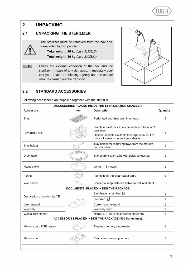
2. UNPACKING
2.1 UNPACKING THE STERILIZER
The sterilizer must be removed from the box and transported by two people.
Total weight: 40 kg (Lisa 317/517) Total weight: 50 kg (Lisa 322/522)
NOTE: Check the external condition of the box and the
sterilizer. In case of any damages, immediately con-tact your dealer or shipping agency and the courier who has carried out the transport.
2.2 STANDARD ACCESSORIES
Following accessories are supplied together with the sterilizer:
ACCESSORIES PLACED INSIDE THE STERILIZATION CHAMBER Accessory Item Description Quantity
Tray
Perforated anodized aluminum tray. 5
Reversible rack
Stainless steel rack to accommodate 5 trays or 3 cassettes. Optional models available (see Appendix 9). For more information contact your dealer.
1
Tray holder
Tray holder for removing trays from the steriliza-tion chamber. 1
Drain tube
Transparent drain tube with quick connector. 1
Mains cable
Length = 2 meters 1
Funnel
Funnel to fill the clean water tank. 1
Wall spacer Spacer to keep distance between wall and steril. 2
DOCUMENTS PLACED INSIDE THE PACKAGE
Sterilization chamber: 1 Declaration of conformity CE
Sterilizer: 1
User manual Current user manual 1 Warranty Warranty card 1 Works Test Report.
Norm EN 13060: small steam sterilizers. 1 ACCESSORIES PLACED INSIDE THE PACKAGE (500 Series only)
Memory card USB reader
External memory card reader 1
Memory card
Reads and saves cycle data 1

4
3. UNIT DESCRIPTION
3.1 FRONT VIEW
3.2 SERVICE DOOR
Sliding cover for manual filling of the clean water tank
Service door
Chamber door
Door seal
Sterilization chamber
Dust filter
Touch- screen
Door pin
Water tank cover
Bacteriological filter
Main switch Serial port (service technicians only)
Slot for memory card (optional for Series 300)
Quick connector for manual draining of
clean water tank
Quick connector for manual draining of used water tank
Connection to unlock the chamber door (service technicians only)

5
3.3 REAR VIEW
Circuit breaker (manual reset)
Mains plug socket
Condenser vent
Mains cable guide
Parallel port (printer)
Data connection for external water supply system
Pressure safety valve cover
Serial port (printer)
Air filter Spare fitting
Fitting for the connec-tion of an external water
supply system
Fitting for continuous draining of used water tank

6
3.4 DESCRIPTION OF THE INTERNAL WATER TANKS
The sterilizer is equipped with two independent water tanks, one for clean water and one for used water (capacity of 3.5 liters each).
The tank on the right side is called "clean water tank" and has to be filled with distilled or demineralized water required for the sterilization process. It is fitted with a minimum (0.6l) and a maximum (3.5l) water level sensor. The tank can be filled manually through the tank hole on the top of the sterilizer or automati-cally with an external water supply system (LisaDem 32 or LisaOsmo) connected to point D2 at the back of the sterilizer (see § 4.5).
Use the quick connector behind the service door (left/blue) to drain the clean water tank for cleaning pur-poses (see chapter on maintenance).
The tank on the left side is called "used water tank" and contains the used water collected at the end of each sterilization cycle. It is fitted with a maximum water level sensor (3.5l).
Use the quick connector behind the service door (right/gray) to drain the used water tank (see chapter on maintenance).
The used water tank can also be drained automatically by connecting a drain tube to the D4 fitting located at the back of the unit (see § 3.3 and § 4.6).
NOTE: The water consumption per sterilization cycle varies depending on the type and weight of the sterilization load. The capacity of the clean water tank is sufficient to run 8 - 12 sterilization cy-cles.
Used water tank
Water level sensors
Quick connector for manual draining of
clean water tank
Quick connector for manual draining of used water tank
Water inlet for manual filling of clean water tank
Fittings for automatic fill-ing/draining of tanks
Clean water tank

7
3.5 CHAMBER RACK
Insert the rack into the sterilization chamber, align it at the center/bottom of the chamber and push it gently into position until it clicks.
The chamber rack is reversible and can be used for:
5 trays horizontally or 3 cassettes vertically
or
3 trays or 3 cassettes horizontally.
3.6 USABLE SPACE IN THE CHAMBER
The chamber usable space is the maximum volume of the chamber for accommodating a sterilization load. This volume is equivalent to a pipe with the following dimensions:
Lisa 317/517 195 x 195 x 297mm (WxHxD); equal to the volume of 11.5 liters
Lisa 322/522 195 x 195 x 390mm (WxHxD); equal to the volume of 15 liters
The capacity/volume is identical for all sterilization cycles and types of load.
H
WD
90°
Click!
Click!

8
4. INSTALLATION
4.1 SETUP
The sterilizer has been calibrated and intensively tested in the factory prior to shipping. It does not require any calibration during installation. Observe the following environmental conditions:
Working temperature range: from +5°C to +40°C / relative humidity: 0 … 90% Storage temperature range: from -20°C to +60°C / relative humidity: 0 … 90% (empty tanks)
Install the sterilizer as outlined below:
• Place the sterilizer on a flat and level surface.
• The maximum weight of the sterilizer with a full clean wa-ter tank and the chamber fully loaded is: 48.5 kg – 57.2 N/m² - 120 N/sq ft. (Lisa 317/517) 58.5 kg – 71 N/m² - 145 N/sq ft. (Lisa 322/522)
• Leave a gap of 50mm in the back and 10mm on each side of the sterilizer to ensure adequate ventilation.Mount the supplied wall spacers at the back of the sterilizer (see image to the right).
• Do not place the sterilizer near a sink or in a location where it is likely to be splashed with water - danger of electric short circuit!
• Install the sterilizer in a well-ventilated room.
• Keep the sterilizer away from all sources of heat.
4.1.1 Securing the sterilizer with a safety bracket
If the bench on which the sterilizer is installed is small, there is a risk of the sterilizer tilting when the chamber door is opened and leaned upon.
Use the safety bracket (optional; see Appendix 9) to avoid that.
- Move the two front feet in the rear position.
- Drill two holes on the installation surface and fix the bracket with the supplied screws.
40113
Refer to safety bracket installation procedures for further details. - Position the sterilizer on the bench with one of the rear feet
inserted in the safety bracket.
Wall
Minimum distance
2 holes Ø3x20
Screws Ø4,8x22

9
4.2 ELECTRICAL POWER SUPPLY
The electrical installation used for the sterilizer must comply with the current standards in the country of use.
- The electrical supply must be single-phase 200-240 VAC ±10%, 50/60 Hz, 10 A on a dedicated circuit. - Installation category / mains overload category = II - Maximum power consumption of the sterilizer is 2,000-2,400 W (10 A) - A grounded connection is essential. The electrical supply to which the sterilizer is connected must be composed of:
- A grounded plug.
- A 10 A differential circuit breaker with a sensitivity of 30 mA. The circuit breaker must be a certified type according to applicable norms.
Plug in the mains cable at the back of the sterilizer.
- Check that the voltage specified on the nameplate located on the backside of the sterilizer corresponds to the supplied mains voltage.
- The overall electrical safety of the sterilizer is guaranteed only if the mains volt-age supply is properly grounded according to all applicable norms.
- If unclear, have the electrical installation checked by a qualified electrician. - Do not plug other equipment into the same socket/circuit. - Do not bend or twist the mains cable. - Use only the original cable as supplied with the sterilizer. - Do not use cable extensions.
4.3 PRINTER (optional)
We recommend the use of LisaPrint (conforms to the IEC 61010-1 norm) as it has been tested for compatibility with the sterilizer and its software. The use of printers other than the ones listed in the relevant printer setup menu (see 6.1.3) clears the manufacturer of any responsibility for warranty or any other claims.
- Connect the printer cable to the 25-pin parallel port socket at the back of the sterilizer. Cable length should not exceed 2 meters.
- Connect the printer mains cable.
- Switch ON the printer.
- Select the printer type (§6.1.3). LisaPrint is the default setting.
All necessary data to document sterilization cycles is printed (for details see Appendix 8).
NOTE: Lisa 517/522 sterilizers offer the option to digitally record cycle data on removable memory cards. Cycle data can be saved, read and printed on a regular PC/MAC (see § 12).

10
LISA 317 06-0123 00.12.00.00.00 ROSSI MARIO Date: 25-10-07 10:48:00 Cycle: B-UNIVERSAL 134 Number: 00001
Expiry date: 22-11-2007
C00EABD00001
4.4 LABEL PRINTER (optional)
We recommend using the printer TLP 2824 (conforms with norm CEI 61010-1) which has been tested and is compatible with the Lisa sterilizer and its software. The use of other printers removes all responsibility from the manufacturer with re-gards to the correct functioning of the system, the guarantee and all other claims.
- Please refer to the label printer manual or quick-start guide for instructions on how to mount the roll of labels and ink ribbon.
- Connect the hardware key to the serial port at the back of the printer.
- Connect the serial cable between the hard-ware key and the serial port at the back of the sterilizer.
- Plug in the printer’s power cable at the mains supply.
- Switch on the printer by pressing the main interrupter on the right-hand side.
- Select the type of printing (automatic or manual) and other options in the sterilizer sub-menus.
- After installation, the printer automatically carries out calibration to obtain the format of the labels used. For this to take place, the label printer must be connected, switched ON with the label roll and ribbon inserted. Access the setup menu, select the label printer option, and select the printer model to be used (see 6.1.4). Carry out the selection procedure to cali-brate the printer, even if the printer is al-ready set to the correct model. During calibration, the printer may use up a few labels, but this is perfectly normal and these labels can be disposed of. If the calibration process has not been car-ried out correctly or it has been carried out correctly but the label format does not cor-respond to that selected for the application, the printer may present anomalies during printing such as blocking, leaving blank la-bels or printing only partial information etc.

11
4.5 DEMINERALIZER (optional)
W&H Sterilization offers external water supply systems for automated supply of demineralized water to the sterilizer(s) (LisaDem32 or LisaOsmo). Once installed, the clean water tank no longer needs to be filled manually but will be filled automatically with demineralized water. The LisaDem32/LisaOsmo utilize resin cartridges to remove minerals from city water to assure a constant good water quality for the sterilization process.
4.5.1 Connecting an external water supply system (demineralizer)
To install a LisaDem32/LisaOsmo water supply system, an interface cable and the fittings D2 and D4 located at the back of the sterilizer are used.
For more information, refer to the LisaDem32/LisaOsmo user manuals.
4.6 CONTINUOUS DRAINING (optional)
4.6.1 Connecting the drain tube
The sterilizer can be connected to a drain (or simply to a sink) for continuous draining of the used water.
- Unscrew the plug from the D4 fitting at the back of the sterilizer.
- Install the 1/8” barber fitting and the drain tube from the kit and route the tube to a drain or sink (kit or-dering number: G0053060). If unclear, have the in-stallation checked by a qualified plumber.
The drain tube must not be longer than 5 meters. The draining point must be at least 20cm below the surface on which the sterilizer is placed.
For further information, refer to the LisaDem32/LisaOsmo user manuals.
Interface cable
D2 = filling
D4 = draining
Drain tube
Drain
12
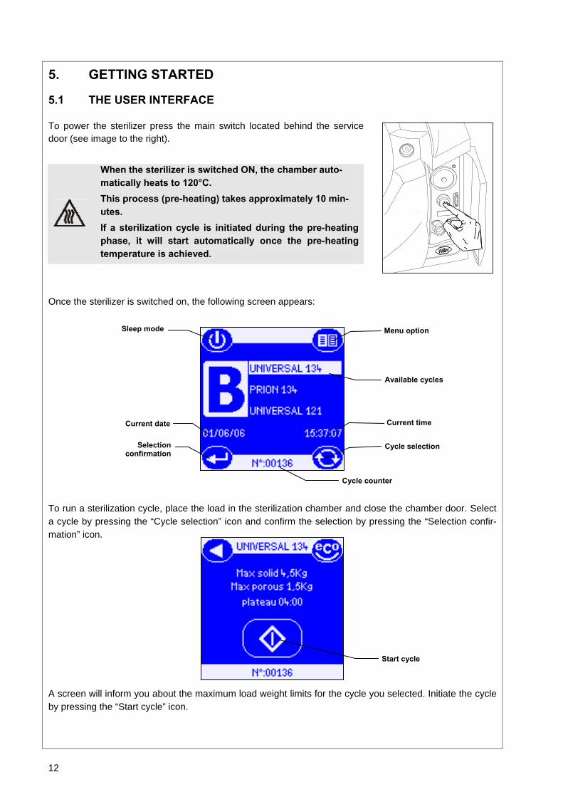
5. GETTING STARTED
5.1 THE USER INTERFACE
To power the sterilizer press the main switch located behind the service door (see image to the right).
When the sterilizer is switched ON, the chamber auto-matically heats to 120°C. This process (pre-heating) takes approximately 10 min-utes. If a sterilization cycle is initiated during the pre-heating phase, it will start automatically once the pre-heating temperature is achieved.
Once the sterilizer is switched on, the following screen appears:
To run a sterilization cycle, place the load in the sterilization chamber and close the chamber door. Select a cycle by pressing the “Cycle selection” icon and confirm the selection by pressing the “Selection confir-mation” icon.
A screen will inform you about the maximum load weight limits for the cycle you selected. Initiate the cycle by pressing the “Start cycle” icon.
Menu option Sleep mode
Available cycles
Current date Current time
Cycle selection
Cycle counter
Selectionconfirmation
Start cycle

13
5.2 INITIAL WARNINGS AND SLEEP MODE
This message will appear if the sterilizer is switched on and the clean water tank is empty. Fill the clean water tank with distilled or demineralized water (see § 5.4).
NOTE: If this message is displayed it is not possible to initiate a sterilization cycle. The mes-sage disappears automatically once the clean water tank is filled.
If the sterilizer is not used for a certain programmable time period, it will automatically switch to “Sleep mode” to conserve energy (programmable time-out; default 1 hour; see § 6.1.2). Press the “Sleep mode” icon to get back to the main menu.
5.3 DATE-CLOCK SETTING
To properly save or print cycle data on a memory card or on a printout, the internal sterilizer time and date has to be set since these parameters are included in the sterilization cycle data report. Please refer to § 6.1.9 for details on how to properly set the sterilizer date and time.
Sleep mode
14
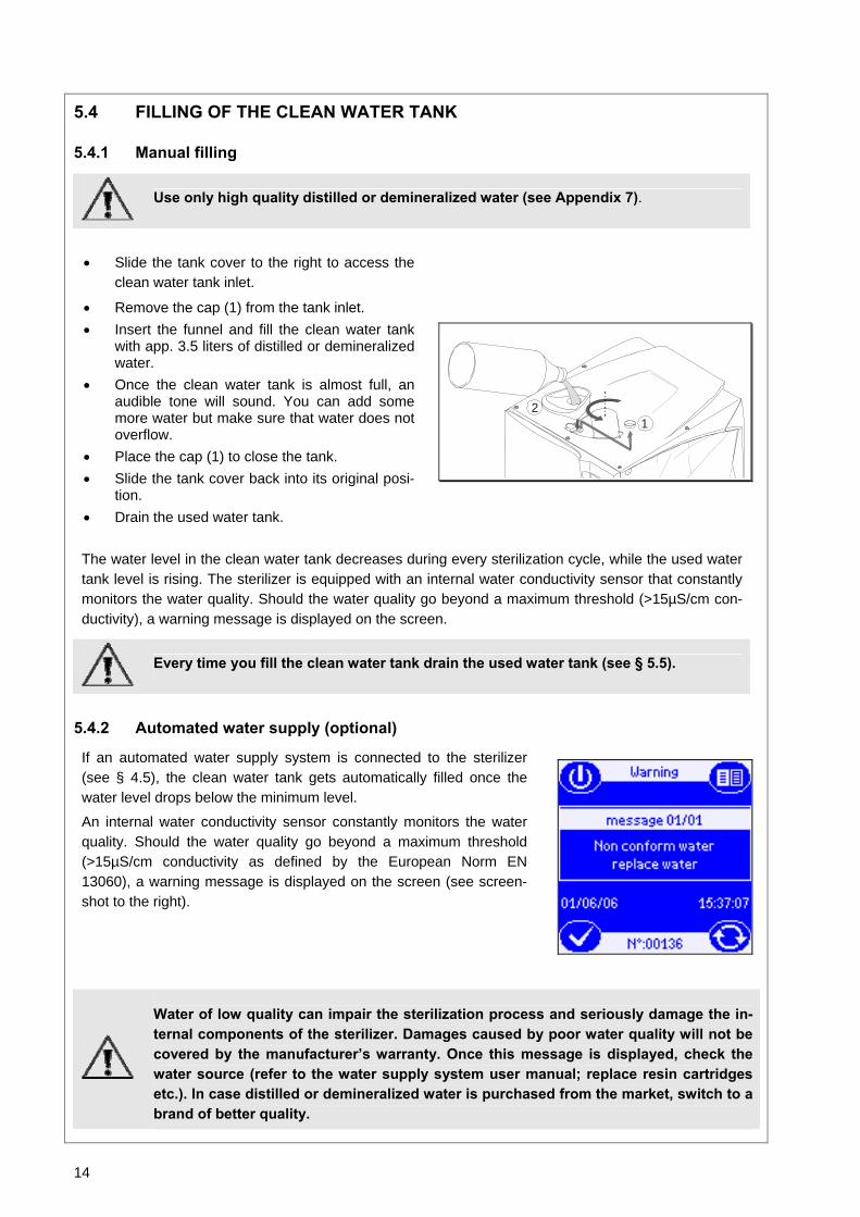
5.4 FILLING OF THE CLEAN WATER TANK
5.4.1 Manual filling
Use only high quality distilled or demineralized water (see Appendix 7).
• Slide the tank cover to the right to access the clean water tank inlet.
• Remove the cap (1) from the tank inlet. • Insert the funnel and fill the clean water tank
with app. 3.5 liters of distilled or demineralized water.
• Once the clean water tank is almost full, an audible tone will sound. You can add some more water but make sure that water does not overflow.
• Place the cap (1) to close the tank. • Slide the tank cover back into its original posi-
tion. • Drain the used water tank.
12
The water level in the clean water tank decreases during every sterilization cycle, while the used water tank level is rising. The sterilizer is equipped with an internal water conductivity sensor that constantly monitors the water quality. Should the water quality go beyond a maximum threshold (>15µS/cm con-ductivity), a warning message is displayed on the screen.
Every time you fill the clean water tank drain the used water tank (see § 5.5).
5.4.2 Automated water supply (optional)
If an automated water supply system is connected to the sterilizer (see § 4.5), the clean water tank gets automatically filled once the water level drops below the minimum level.
An internal water conductivity sensor constantly monitors the water quality. Should the water quality go beyond a maximum threshold (>15µS/cm conductivity as defined by the European Norm EN 13060), a warning message is displayed on the screen (see screen-shot to the right).
Water of low quality can impair the sterilization process and seriously damage the in-ternal components of the sterilizer. Damages caused by poor water quality will not be covered by the manufacturer’s warranty. Once this message is displayed, check the water source (refer to the water supply system user manual; replace resin cartridges etc.). In case distilled or demineralized water is purchased from the market, switch to a brand of better quality.

15
5.5 DRAINING OF THE USED WATER TANK
When the waste water in the used water tank reaches the maximum level, the following message is displayed:
The message will disappear once the used water tank got drained. Keep draining the tank until it is completely empty.
5.5.1 Manual draining
• Open the service door at the front of the sterilizer.
• Insert the drain tube into the quick connector for the used water (gray connector / right).
• Let the used water tank drain until it is completely empty.
• Press the push-button on top of the quick connector to dislodge the drain tube.
NEVER RE-USE THE USED WATER!
5.5.2 Continuous draining
If the permanent drain tube for automated draining of the used water is mounted, the used water tank gets drained automatically. For more information see § 4.6.
If the sterilizer is not used for more than 3 days, both water tanks must be com-pletely drained in order to avoid algae growth or any other deposits.
5.6 MEMORY CARD (optional for 300 Series)
5.6.1 Inserting / removing the memory card
All models of the Lisa 500 Series (optional for 300 Series) are equipped with a digital cycle data recording system. Cycle data is written and saved on removable/rewritable memory cards. - Insert the memory card into the dedicated slot behind the service
door until it clicks into its final position. Ensure that the flat corner of the card points to the top/right (see image to the right).
- Periodically remove the memory card to download cycle data to a computer.
- To remove the memory card, slighty push it in and pull it out gently.
For further instructions on the use of the memory card, see § 12.
16
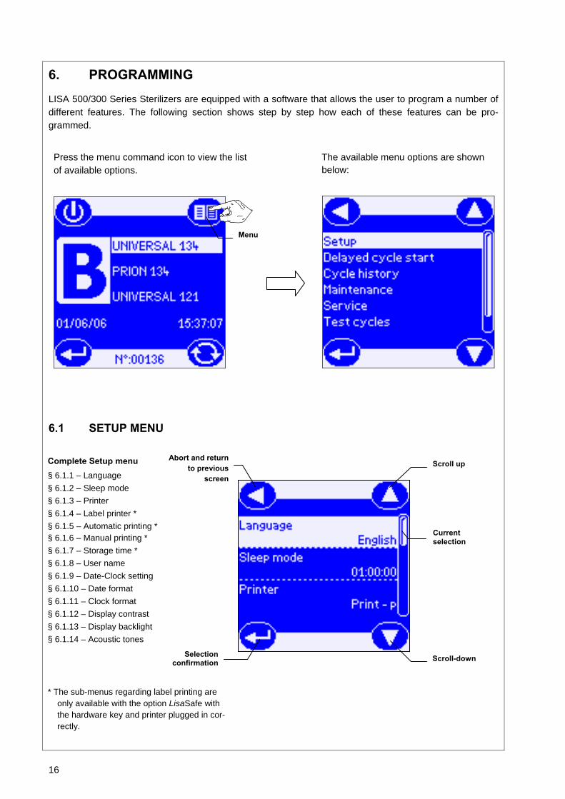
6. PROGRAMMING
LISA 500/300 Series Sterilizers are equipped with a software that allows the user to program a number of different features. The following section shows step by step how each of these features can be pro-grammed.
Press the menu command icon to view the list of available options.
The available menu options are shown below:
6.1 SETUP MENU
Complete Setup menu § 6.1.1 – Language § 6.1.2 – Sleep mode § 6.1.3 – Printer § 6.1.4 – Label printer * § 6.1.5 – Automatic printing * § 6.1.6 – Manual printing * § 6.1.7 – Storage time * § 6.1.8 – User name § 6.1.9 – Date-Clock setting § 6.1.10 – Date format § 6.1.11 – Clock format § 6.1.12 – Display contrast § 6.1.13 – Display backlight § 6.1.14 – Acoustic tones
* The sub-menus regarding label printing are only available with the option LisaSafe with the hardware key and printer plugged in cor-rectly.
Menu
Abort and return to previous
screen Scroll up
Scroll-down
Current selection
Selection confirmation
17
6.1.1 Language
Use this menu to select the user interface language.
6.1.2 Sleep mode
In “Sleep mode” the sterilizer reduces the power consumption to a minimum. The sterilizer will switch to sleep mode whenever it is idling without being used. Use this menu to program the time before the steri-lizer switches to sleep mode.
• The time range is from 0 (never in sleep mode) to 8 hours. The factory setting is 1 hour. • The time can be set in fixed increments of 10 minutes.
6.1.3 Printer
Use this menu if you want to connect a printer for cycle data recording. Select the printer by using the scroll icons, press “Confirm” to save the configuration. For more information on connecting a printer to your sterilizer, see § 4.3.
Abort and return to previous screen Scroll up
Cursor
Scroll down Selection confirmation
Abort and return to previous screen Increase time
Decrease time Selection
confirmation
Scroll up
Current selection
Scroll down Confirm and return to
previous menu
Abort and return to previous screen

18
6.1.4 Label printer (available with LisaSafe option)
This menu allows labels to be printed. Select the printer using the scroll icons. Press the confirm icon to confirm your choice.
Note: - This printing function requires a software superior or equal to version "00.12.xx.xx.xx.xx". Contact
your supplier if a software upgrade is necessary. - Selecting “No printer” prevents label printing even if the label printer is connected and switched
on.
- The selection of this option could initiate calibration whereby the printer obtains the format of the labels used ( see 4.4)
6.1.5 Automatic printing (available with LisaSafe option)
In this menu it is possible to select the number of stickers to be automatically printed at the end of each cy-cle without having to intervene each time. Increase or decrease the desired quantity using the scroll icons. Press the confirm icon to confirm your selection. For example: 4: 1 sticker each for 3 cassettes and a fourth for the cycle log-book. Automatic printing only takes place if the sterilization cycle has been successful, therefore it is not to be considered an anomaly if labels are not printed at the end of a test cycle or cycle stopped manually or ter-minated incorrectly. If more labels are required, they can be printed by entering the “Cycle history” menu (see 6.3)
Confirm and return to previous menu
Quantity selected
More
Fewer
Abort and return to previous screen
Current selection
Scroll up
Scroll downConfirm and return to previous menu
Abort and return to previous screen

19
LISA 317 06-0123 00.12.00.00.00 ROSSI MARIO Date: 25-10-07 10:48:00 Cycle: B-UNIVERSAL 134 Number: 00001
Expiry date: 22-11-2007
C00EABD00001
LISA 317 06-0123 00.12.00.00.00 ROSSI MARIO Date: 22-10-07 10:48:00 Cycle: B-UNIVERSAL 134 Number: 00001
Cycle Completed
C00EABD00001
6.1.6 Manual printing (available with LisaSafe option)
If it is preferred to print labels after having checked the load (after opening the sterilizer door) it is possible to set the manual print option.Select the option using the scroll icons. Press the confirm icon to confirm the selection.
This option allows a label printing screen to appear immediately after opening the door without having to access the cycle history (see 6.3).
The label printing screen only appears if a sterilization cycle has ended correctly, therefore it is not an anomaly if the screen is not displayed after opening the door at the end of a test cycle or at the end of a sterilization cycle interrupted manually or terminated incorrectly.
If extra labels are required, they can be printed by entering the “Cycle History” menu (see 6.3).
6.1.7 Storage time/weeks (available with LisaSafe option)
If it is planned to store the sterilized load for a maximum period, it is possible to insert a set storage time in this screen and automatically obtain the information relative to the expiry date on the label.
If the set time is equal to zero, no expiry date is shown in the on the label
If the set time (in weeks) is different to zero, the expiry date is automatically calculated according to the cycle start date
NOTE: The expiry date appears only when a cycle has terminated successfully, therefore it is not con-sidered an anomaly if the expiry date is missing and replaced by the cycle outcome in the case of test cycles or sterilization cycles interrupted manually or that have ended incorrectly.
The setting of a storage time only has effect on the cycles performed thereafter, and does not have any effect on the cycles that have already been carried out.
Use a storage time in conformity with the recommendations of the manufacturers of the devices to be sterilized and of the containers/packaging used, and according to the current norms.
Abort and return to previous screen
Confirm and return to previous menu
Scroll up
Type selected
Scroll down

20
6.1.8 User name
Use this menu to program the user or the office name. The name will be included in the cycle data report. Select a character by pressing the ”Increment” or “Decrement” icons. Press the “Move next” icon to move to the next position. When the setting is completed, press the “Confirm” icon.
6.1.9 Date-Clock setting
Use this menu to set the internal time and date of the sterilizer. It is important to set these parameters as they are included in the cycle data report.
Select a character by pressing the ”Increment” or “Decrement” icons. Press the “Move next” icon to go to the next position. When the setting is completed, press the “Confirm” icon.
Increment
Abort and return to previous screen Scroll up
Time duration selected
Scroll down Confirm and return to previous menu
Abort and return to previous menu
Decrement
Move next
User or office name
Confirm and return to previous menu
Abort and return to
previous screen Increment
Decrement
Confirm and return to previous menu
Date Time
Move next

21
6.1.10 Date format
Use this menu to change the date format. Press the “Scroll up” and “Scroll down” icons to select the for-mat. Press the “Confirm” icon to save the selection.
6.1.11 Clock format
Use this menu to change the clock format. Press the “Scroll up” and “Scroll down” icons to select the for-mat. Press the “Confirm” icon to save the selection.
6.1.12 Display contrast
Use this menu to change the screen contrast for a better visualization in regards to the surrounding envi-ronment. Press the “Increase contrast” and “Decrease contrast” icons to adjust the contrast. Press the “Confirm” icon to save the selection.
Abort and return to previous screen Scroll up
Scroll down Confirm and return to
previous screen
Abort and return to previous screen Scroll up
Scroll down Confirm and return to
previous screen
Abort and return to previous screen Increase contrast
Decrease contrast Confirm and return to
previous screen
22
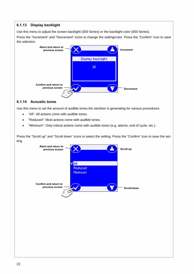
6.1.13 Display backlight
Use this menu to adjust the screen backlight (300 Series) or the backlight color (500 Series).
Press the “Increment” and “Decrement” icons to change the setting/color. Press the “Confirm” icon to save the selection.
6.1.14 Acoustic tones
Use this menu to set the amount of audible tones the sterilizer is generating for various procedures:
• “All”: All actions come with audible tones.
• “Reduced”: Most actions come with audible tones.
• “Minimum”: Only critical actions come with audible tones (e.g. alarms, end of cycle, etc.).
Press the “Scroll up” and “Scroll down” icons to select the setting. Press the “Confirm“ icon to save the set-ting.
Abort and return to previous screen Increment
Decrement Confirm and return to
previous screen
Abort and return to previous screen Scroll-up
Scroll-down Confirm and return to
previous screen

23
6.2 DELAYED CYCLE START
Use this menu to delay the start of the selected cycle (e.g. if you want to load the sterilizer in the evening and run a cycle early the following morning before office hours). It is possible to set both the date and the time in which the selected cycle will start. Place the sterilization load in the chamber, close the chamber door, press the "Menu" icon on the main screen and select "Delayed cycle start" from the menu (see § 6). Select the desired cycle by pressing the “Scroll up” and “Scroll down” icons. Press the “Press to set” icon to set the delayed cycle time and date.
Set date and time by pressing the “Incre-ment” or “Decrement” icons. Press the “Move next” icon to go to the next charac-ter. When the setting is completed, press the “Confirm” icon to get to the next screen.
On this screen, the maximum load weight limits for the selected cycle are shown. Press the "Cycle start" icon to launch the delayed cycle.
The current and the set delayed date and time appear on the screen indicating when the delayed cycle will start.
Confirm set-tings and en-
ter next screen
Abort and return to pre-vious screen
Increment
Set date
Set time
Decrement
Move next
Return to previ-ous screen
Cycle counter
Cycle start
Manual stop
Current date and time
Delayed cycle date and time
Return to pre-vious screen
Scroll up
Scroll downPress to set
24
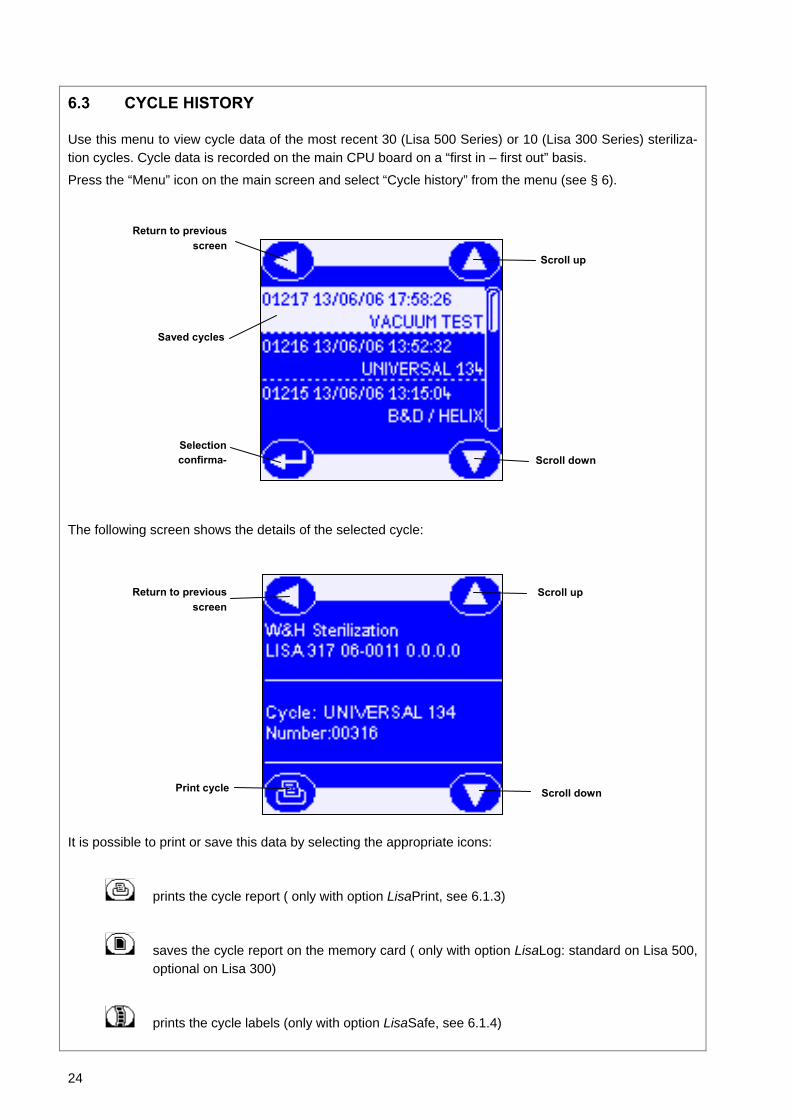
6.3 CYCLE HISTORY
Use this menu to view cycle data of the most recent 30 (Lisa 500 Series) or 10 (Lisa 300 Series) steriliza-tion cycles. Cycle data is recorded on the main CPU board on a “first in – first out” basis.
Press the “Menu” icon on the main screen and select “Cycle history” from the menu (see § 6).
The following screen shows the details of the selected cycle:
It is possible to print or save this data by selecting the appropriate icons:
prints the cycle report ( only with option LisaPrint, see 6.1.3)
saves the cycle report on the memory card ( only with option LisaLog: standard on Lisa 500, optional on Lisa 300)
prints the cycle labels (only with option LisaSafe, see 6.1.4)
Return to previous screen
Selection confirma-
Scroll up
Scroll down
Saved cycles
Return to previous screen
Scroll up
Scroll down Print cycle

25
If up to 2 options are active, the available options will immediately be displayed
If more than two options are active, a selection key appears so as to be able to choose the desired option

26
6.4 MAINTENANCE
Certain consumables have to be replaced periodically to guarantee a faultless operation of the sterilizer. Display messages will inform you whenever it is time to replace one of those components (see § 8).
Press the "Menu" icon on the main screen and select "Maintenance" from the menu (see § 6). Use this menu to view the number of cycles remaining before it is time to replace the:
• bacteriological filter (every 400 cycles)
• dust filter (every 400 cycles)
• door seal (every 1000 cycles)
• or perform a general service by a qualified technician (every 4000 cycles)
The 4 counters decrease in value after each cycle. When one of the counters reaches 0, the corre-sponding message appears on the touch-screen (see § 8).
In case a consumable gets replaced before the respective counter has reached 0, the counter has to be reset manually:
• Select the counter you wish to reset by pressing the ”Scroll up” and “Scroll down” icons.
• Reset the counter by pressing the “Confirm reset” icon.
• Select "Yes" or "No" from the maintenance screen shown below.
To guarantee an efficient sterilization process and the correct functioning of the unit, we strongly recommend to follow the maintenance program (see § 11.1).
6.5 SERVICE
This menu is used for service and diagnostic operations. It can be accessed by authorized service techni-cians only.
Scroll up
Scroll down Confirm reset Yes No
27
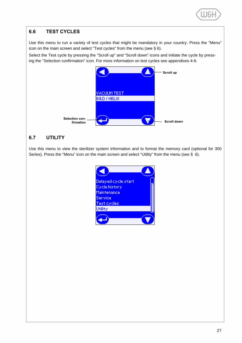
6.6 TEST CYCLES
Use this menu to run a variety of test cycles that might be mandatory in your country. Press the "Menu" icon on the main screen and select "Test cycles" from the menu (see § 6).
Select the Test cycle by pressing the ”Scroll up” and “Scroll down” icons and initiate the cycle by press-ing the "Selection confirmation" icon. For more information on test cycles see appendixes 4-6.
6.7 UTILITY
Use this menu to view the sterilizer system information and to format the memory card (optional for 300 Series). Press the “Menu” icon on the main screen and select “Utility” from the menu (see § 6).
Selection con-firmation Scroll down
Scroll up

28
6.7.1 System info
Use this menu to view the sterilizer system informa-tion.
• Model
• Serial Number
• Firmware revision
• Loader revision
• Power FW revision
6.7.2 Formatting the memory card (optional for 300 Series)
Use this menu to format your memory card in case you want to erase all the data on the card. Press the “Menu” icon on the main screen and select “Utility” from the menu (see § 6). Press “Format MMC” to initi-ate the formatting.
The system first verifies the card.
Next you will see this screen asking if you want to format the card. Press "Confirm" to proceed with the formatting or "Cancel" to exit the for-matting menu.
If you confirm to proceed with formatting, all data will be lost on the card. Press “Cancel” to exit the formatting menu.
Once the formatting is completed, the card is ready to be used.
Cancel Confirm
Cancel Confirm
29
7. RUNNING A STERILIZATION CYCLE
7.1 THE AVAILABLE STERILIZATION CYCLE PROGRAMS
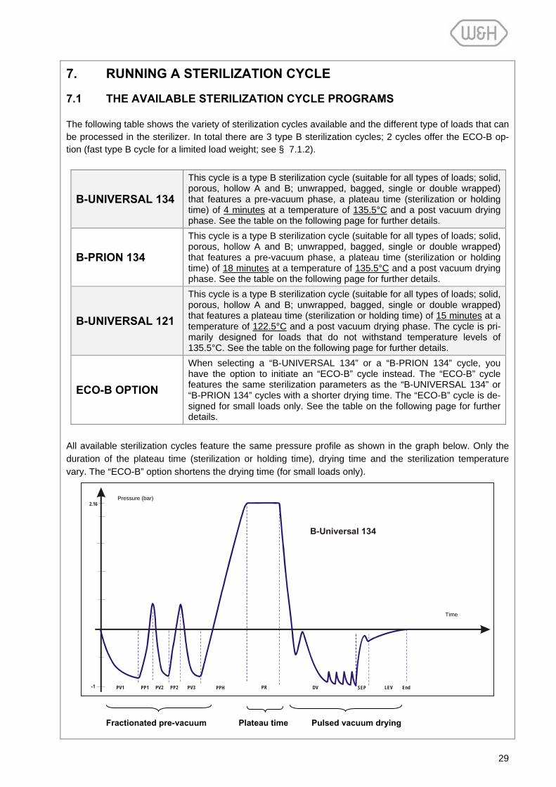
The following table shows the variety of sterilization cycles available and the different type of loads that can be processed in the sterilizer. In total there are 3 type B sterilization cycles; 2 cycles offer the ECO-B op-tion (fast type B cycle for a limited load weight; see § 7.1.2).
B-UNIVERSAL 134
This cycle is a type B sterilization cycle (suitable for all types of loads; solid, porous, hollow A and B; unwrapped, bagged, single or double wrapped) that features a pre-vacuum phase, a plateau time (sterilization or holding time) of 4 minutes at a temperature of 135.5°C and a post vacuum drying phase. See the table on the following page for further details.
B-PRION 134
This cycle is a type B sterilization cycle (suitable for all types of loads; solid, porous, hollow A and B; unwrapped, bagged, single or double wrapped) that features a pre-vacuum phase, a plateau time (sterilization or holding time) of 18 minutes at a temperature of 135.5°C and a post vacuum drying phase. See the table on the following page for further details.
B-UNIVERSAL 121
This cycle is a type B sterilization cycle (suitable for all types of loads; solid, porous, hollow A and B; unwrapped, bagged, single or double wrapped) that features a plateau time (sterilization or holding time) of 15 minutes at a temperature of 122.5°C and a post vacuum drying phase. The cycle is pri-marily designed for loads that do not withstand temperature levels of 135.5°C. See the table on the following page for further details.
ECO-B OPTION
When selecting a “B-UNIVERSAL 134” or a “B-PRION 134” cycle, you have the option to initiate an “ECO-B” cycle instead. The “ECO-B” cycle features the same sterilization parameters as the “B-UNIVERSAL 134” or “B-PRION 134” cycles with a shorter drying time. The “ECO-B” cycle is de-signed for small loads only. See the table on the following page for further details.
All available sterilization cycles feature the same pressure profile as shown in the graph below. Only the duration of the plateau time (sterilization or holding time), drying time and the sterilization temperature vary. The “ECO-B” option shortens the drying time (for small loads only).
-1
2.16
PR DV LEV SEP End
B-Universal 134
PV1 PV2 PV3 PP1 PP2 PPH
Fractionated pre-vacuum Plateau time Pulsed vacuum drying
Pressure (bar)
Time

30
Legend:
PV1 – PV3 Vacuum pulse (removal of air from the sterilization chamber/load)
PP1 - PP2 Pressure pulse (steam injection)
PPH Pressure pulse and heating (steam injection and heating to sterilization temp.)
PR Process (plateau/sterilization/holding time)
DV Vacuum drying
SEP Water separator draining phase
LEV Leveling
STERILIZATION CYCLES TEST CYCLES
B-Universal 134 B-Prion 134 B-Universal 121 Helix B&D
Air leakage Vacuum test
Temperature 135.5°C 135.5°C 122.5°C 135.5°C --
Pressure 2.16 bar 2.16 bar 1.16 bar 2.16 bar -0.86bar
Duration of the plateau phase 4' 18' 15' 3'30 10'
Duration of the drying phase 15' 15' 20' 4' --
Lisa 517 Lisa 317
ECO-B
20’ > 21’
Full Load
38’ 40’
ECO-B
34’ 37’
Full Load
52’ 54’
EMPTY
41’ 44’
Full Load
56’ 60’
23’ 24’ TOTAL CYCLE
DURATION Lisa 522 Lisa 322
21’ 25’
48’ 52’
35’ 39’
62’ 66’
42’ 46’
62’ 65’
26’ 25’
Full solid (probes, tweezers, burs,…) YES YES YES
Small porous items (gauze, cotton,…) YES YES YES
Full porous (80% of the usable space). YES YES YES
Hollow A (hand pieces, forceps, scissors,) YES YES YES
Hollow B (vacuum tips,…) YES YES YES
LOA
D T
YPE
Unwrapped, bagged, single/double wrapped YES YES YES
MAXIMUM LOAD WEIGHT LIMITS:
SOLID / POROUS
0.5/0.2 kg all models
4.5/1.5 kg 317&517
6.0/2.0 kg 322&522
0.5/0.2 kg all models
4.5/1.5 kg317&517
6.0/2.0 kg322&522
4.5 / 1.5 kg 317 & 517
6.0 / 2.0 kg 322 & 522
Empty chamber
or test pack
see Appendix 4 - 6
Total type-B concept: All available cycles can sterilize and dry all types of loads: full solid, porous, hollow A, hollow B, plastics, rubber, etc.; unwrapped, bagged, single or double wrapped, but :
For preparation of the load, follow the instructions provided by the manufacturer. For guaranteed sterilization, stay within the max. load weight limits as specified in this table.

31
7.1.1 Starting a sterilization cycle
Exit from sleep mode by pressing the "Sleep mode" icon.
Select a cycle by pressing the "Cycle selection" icon and confirm the selection by pressing the "Selection confirmation" icon.
Once a cycle is selected and confirmed, the following screen informs about the maximum load weight lim-its that can be processed with the selected cycle (see cycle table § 7.1 for further information). Press the "Start cycle" icon to initiate the selected cycle.
7.1.2 ECO-B option
The “ECO-B” option is intended to reduce the total cycle duration of a standard cycle, providing a quick type B cycle for a limited load weight. The “ECO-B” option is available for the “B-UNIVERSAL 134” and “B-PRION 134” sterilization cycles and can be selected for loads with the following maximum weight limits: 0.5 kg solid / 0.2 kg porous; unwrapped, single or double wrapped/bagged. The sterilization parameters of the “ECO-B” cycle are the same as the ones of the “B-UNIVERSAL 134” and “B-PRION 134” cycles (pre- and post-vacuum; plateau time of 4/18 minutes at a sterilization temperature of 135.5°C); the only difference is the shorter drying time.
To run a quick “ECO-B” cycle, select a “B-UNIVERSAL 134” or “B-PRION 134” cycle from the main menu (see § 7.1.1) and instead of initiating that cycle, press the “ECO-option” icon. Once the “ECO-B” cycle op-tion has been selected, the following message informs about the maximum load weight limits that can be processed. To initiate the cycle press the “Start cycle” icon.
Enter sleep modeMenu option
Return to previous menu
ECO option
Start cycle
Exit sleep mode
Selection confirmation Cycle selection

32
NOTE:
If the “ECO-B” option is selected and the actual load weight exceeds the maximum limit as specified on the screen, the sterilizer will automatically switch from the "ECO-B" cycle to the standard "B-UNIVERSAL 134" or “B-PRION 134” cycle to ensure proper drying of the load.
When selecting the "ECO-B" option, always place the load on the upper tray of the chamber rack and remove all other trays from the chamber. Ensure that the paper side of sterilization bags faces up.
7.1.3 Cycle in-progress
While a cycle is in progress, the following parameters are displayed on the touch-screen: • Sterilization temperature and pressure – measured inside the chamber. • Elapsed time – time elapsed from the beginning of the sterilization cycle. • Residual time - time remaining until cycle completion. • Current cycle phase (e.g. PV1) • Cycle counter • Cycle name
In the central part of the screen, a simplified cycle pressure profile is shown. As the cycle proceeds, a pro-gress bar overwrites the completed cycle pressure profile, showing in real time the actual phase the cycle is in. If you press the "Info" icon, further technical parameters are displayed. The "Info" icon can be pressed at any time, also if there is no cycle in progress; it provides important information especially for service tech-nicians.
Return to previous menu
Start cycle
ECO option
Cycle counter
Info Manual stop
Elapsed time
Cycle pressure profile
Progress bar
Cycle phase
Residual time
Cycle name
33
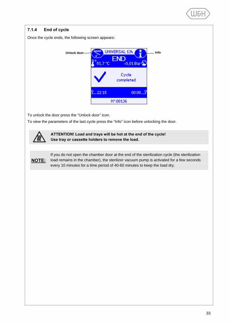
7.1.4 End of cycle
Once the cycle ends, the following screen appears:
To unlock the door press the “Unlock door” icon.
To view the parameters of the last cycle press the “Info” icon before unlocking the door.
NOTE:
If you do not open the chamber door at the end of the sterilization cycle (the sterilization load remains in the chamber), the sterilizer vacuum pump is activated for a few seconds every 10 minutes for a time period of 40-60 minutes to keep the load dry.
ATTENTION! Load and trays will be hot at the end of the cycle! Use tray or cassette holders to remove the load.
Info Unlock door
34
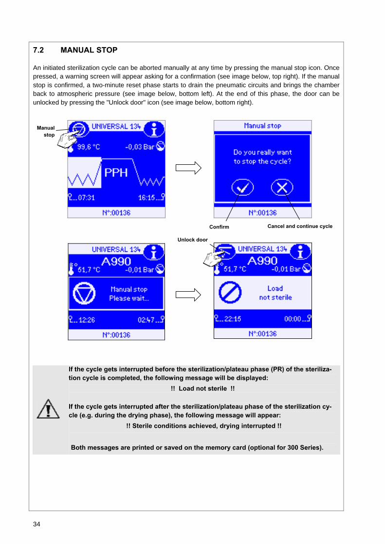
7.2 MANUAL STOP
An initiated sterilization cycle can be aborted manually at any time by pressing the manual stop icon. Once pressed, a warning screen will appear asking for a confirmation (see image below, top right). If the manual stop is confirmed, a two-minute reset phase starts to drain the pneumatic circuits and brings the chamber back to atmospheric pressure (see image below, bottom left). At the end of this phase, the door can be unlocked by pressing the "Unlock door" icon (see image below, bottom right).
If the cycle gets interrupted before the sterilization/plateau phase (PR) of the steriliza-tion cycle is completed, the following message will be displayed:
!! Load not sterile !!
If the cycle gets interrupted after the sterilization/plateau phase of the sterilization cy-cle (e.g. during the drying phase), the following message will appear:
!! Sterile conditions achieved, drying interrupted !! Both messages are printed or saved on the memory card (optional for 300 Series).
Manual stop
Cancel and continue cycle Confirm
Unlock door
35
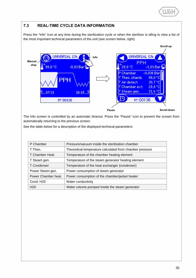
7.3 REAL-TIME CYCLE DATA INFORMATION
Press the “Info” icon at any time during the sterilization cycle or when the sterilizer is idling to view a list of the most important technical parameters of the unit (see screen below, right).
The info screen is controlled by an automatic timeout. Press the “Pause” icon to prevent the screen from automatically returning to the previous screen.
See the table below for a description of the displayed technical parameters:
P Chamber Pressure/vacuum inside the sterilization chamber T Theo. Theoretical temperature calculated from chamber pressure T Chamber Heat Temperature of the chamber heating element T Steam gen. Temperature of the steam generator heating element T Condenser Temperature of the heat exchanger (condenser) Power Steam gen. Power consumption of steam generator Power Chamber heat. Power consumption of the chamber/jacket heater Cond. H20 Water conductivity H20 Water volume pumped inside the steam generator
Manual stop
Info
Scroll-up
Scroll-downPause

36
7.4 CYCLE DATA SUMMARY
Press the "Info" icon at the end of a cycle before unlocking the chamber (see image below, left) to view a summary of the cycle parameters (see images below, middle and right).
The information screen lists the following parameters:
• Cycle name
• Cycle counter
• Time/duration, pressure and temperature readings at the end of each cycle phase.
• Temperature and pressure readings of the actual sterilization/plateau phase
Legend:
PV Vacuum pulse (air removal) PP Pressure pulse (steam injection) PPH Pressure pulse and heating PR Process (Sterilization/plateau phase) DV Vacuum drying

37
8. DISPLAY MESSAGES
Once the sterilizer is switched on a variety of messages can appear on the touch-screen. Messages show the status of the sterilizer; an example is shown to the right. A message counter indicates the number of messages pending (e.g. message 01/02). Messages are divided in three main catego-ries:
• Warning messages • Information messages • Maintenance messages
Check the table below for instructions on how to respond to the various messages:
WARNING MESSAGES
Message Description Action
Fill water tank The clean water tank is empty. Fill the clean water tank with distilled or demine- ralized water (see § 5.4).
Drain used water tank The used water tank is full. Drain the used water tank (see § 5.5).
Door locking system problem - Try again
The door could not be locked / unlocked properly.
Control (clean) the door seal and try again.Call for service if the message persists.
Note: When these messages appear on the screen, the cycle selection command is disabled. It is not possible to initiate a cycle until the necessary action is carried out.
INFORMATION MESSAGES
Non conform water replace water
According to the sterilizer water con-ductivity sensor, the water quality (in terms of µS) does not conform to the norm and it may damage the sterilizer (see Appendix 7).
Completely drain the clean water tank and refill it with water of good quality. If you use an automated water supply system, check and replace resin filters.
Unacceptable water DO NOT run cycle!
According to the sterilizer water con-ductivity sensor, the water quality (in terms of µS) does not conform to the norm and it may seriously damage the sterilizer (see Appendix 7).
Completely drain the clean water tank and refill it with water of good quality. If you use an automated water supply system, check and replace resin filters.
CPU battery flat The CPU board battery is worn. Call for service.
Messagecounter
Message

38
MAINTENANCE MESSAGES
Message Description Action Replace bacteriological
filter This message informs that the bacterio-logical filter needs to be replaced.
Replace bacteriological filter (see § 11.6).
Replace dust filter This message informs that the dust filter needs to be replaced.
Replace dust filter (see § 11.7).
Replace door seal This message informs that the door seal needs to be replaced.
Replace door seal (see § 11.9).
Clean clear and used water tanks
This message informs that the water tanks need to be cleaned.
Clean the water tanks (see § 11.8).
4000 cycles reached Call for service
This message informs that a 4000 cycle overhaul needs to be performed. Call for service.
Note: When these messages appear on the screen:
• It is not possible to initiate a cycle (the cycle selection icon will disappear). • The message must be acknowledged by pressing the “Confirm” icon. • The “Yes” or “No” option from the "Reset counter" screen must be selected. • The necessary actions must be carried out as described above.
The "Reset counter" function allows the user to postpone the necessary action (e.g. when the consumable part to be replaced is not available).
If you press the “Yes” icon, the maintenance message will disappear and the maintenance counter will be reinitialized. If you press the “No” icon, the maintenance message will reappear after five cycles and the counter will keep counting up.
Lisa sterilizers must be maintained according to the maintenance program (see § 11.1). Inadequate or inappropriate maintenance can lead to frequent malfunctions and expensive repairs and may void the manufacturer’s warranty.
Yes
No
39
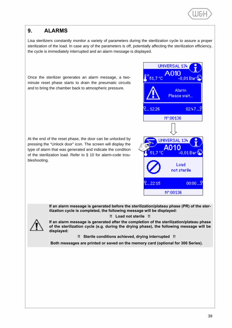
9. ALARMS
Lisa sterilizers constantly monitor a variety of parameters during the sterilization cycle to assure a proper sterilization of the load. In case any of the parameters is off, potentially affecting the sterilization efficiency, the cycle is immediately interrupted and an alarm message is displayed.
Once the sterilizer generates an alarm message, a two-minute reset phase starts to drain the pneumatic circuits and to bring the chamber back to atmospheric pressure.
At the end of the reset phase, the door can be unlocked by pressing the “Unlock door” icon. The screen will display the type of alarm that was generated and indicate the condition of the sterilization load. Refer to § 10 for alarm-code trou-bleshooting.
If an alarm message is generated before the sterilization/plateau phase (PR) of the ster-ilization cycle is completed, the following message will be displayed:
!! Load not sterile !! If an alarm message is generated after the completion of the sterilization/plateau phase of the sterilization cycle (e.g. during the drying phase), the following message will be displayed: !! Sterile conditions achieved, drying interrupted !! Both messages are printed or saved on the memory card (optional for 300 Series).

40
10. ALARM CODE TABLE
Refer to the table below for troubleshooting assistance in case the sterilizer generates an alarm code.
Code Description Action
Power supply
A010 Power failure or significant fall in voltage occurred during the cycle.
The load cannot be considered sterile.
The cycle must be repeated.
Sterilization chamber
A100 The time it took to reach the sterilization plateau is too long (overload, leaks, etc.).
Observe the max. load weight limits, clean/check the door seal and the face side of the chamber and re-peat the cycle.
If the problem persists service.
A130 During the sterilization phase of the cycle, the pres-sure measured inside the sterilization chamber is above the maximum threshold.
Repeat the cycle.
If the problem persists service.
A140 During the sterilization phase of the cycle, the pres-sure measured inside the sterilization chamber is below the minimum threshold.
Repeat the cycle.
If the problem persists service.
A150 During the sterilization phase of the cycle, the tem-perature of the steam is below the minimum threshold.
Repeat the cycle.
If the problem persists service.
A160 During the sterilization phase of the cycle, the tem-perature of the steam is above the maximum threshold.
Repeat the cycle.
If the problem persists service.
A170 The temperature sensor of the chamber heating element is broken or disconnected. service
A180 The internal temperature sensor of the chamber is broken or disconnected. service
A190 “Air Detector” alarm (Lisa 500 Series) Repeat the cycle.
If the problem persists service.
Steam generator
A230 The temperature sensor of the steam generator is broken or disconnected. service
A240 Fault of the steam generator heater. service
A250 The internal temperature sensor of the “Air Detec-tor” system is broken or disconnected. (Lisa 500 Series)
service

41
Code Description Action
Vacuum pump
A310 During a vacuum phase of the cycle, a vacuum of –0.20 bar or lower could not be achieved.
Clean and check the door seal (§ 11.2) and the face side of the chamber; repeat the cycle. If the problem persists service.
A320 During a vacuum phase of the cycle, a vacuum of –0.50 bar or lower could not be achieved.
Clean and check the door seal (§ 11.2) and the face side of the chamber; repeat the cycle. If the problem persists service.
A321 Timeout: set point in PV1..3 not reached service
A350 Vacuum pump fault service
A380 Leak between the reading points P1 and P2 of the Vacuum Test
Clean and check the door seal (§ 11.2) and the face side of the chamber; repeat the test. If the problem persists service.
A390 Leak between the reading points P2 and P3 of the Vacuum Test
Clean and check the door seal (§ 11.2) and the face side of the chamber; repeat the test. If the problem persists service.
Water pump
A400 Water pump fault service
A410 Water conductivity meter fault service
A420 Flow meter fault service
Door locking
A520 The chamber door locking mechanism blockedduring opening. service
A530 The chamber door locking mechanism blockedduring closing. service
Electric valves
A601…8 Electric valve A…..H fault service
Condenser
A720 Fan fault service
Water tanks
A810 Water level sensor fault service
Manual stop
A990 The “Manual stop” icon was pressed Wait until the end of the reset phase (see § 7.2).
42
11. MAINTENANCE
There are two levels of maintenance:
- Maintenance performed regularly by the user.
- Preventive maintenance carried out by an authorized service technician (see § 11.10).
Before carrying out any maintenance on the unit, remove the mains cable.
11.1 MAINTENANCE PROGRAM
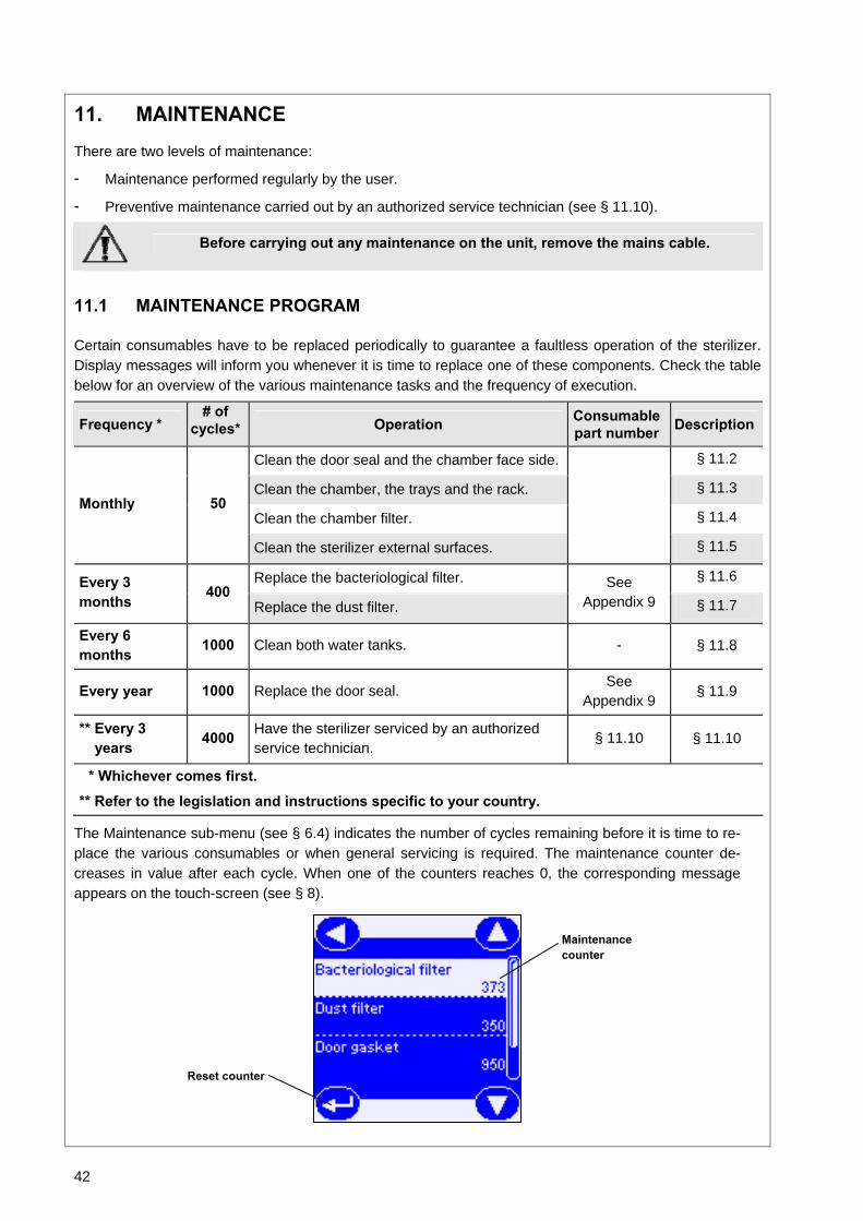
Certain consumables have to be replaced periodically to guarantee a faultless operation of the sterilizer. Display messages will inform you whenever it is time to replace one of these components. Check the table below for an overview of the various maintenance tasks and the frequency of execution.
Frequency * # of
cycles* Operation Consumable part number Description
Clean the door seal and the chamber face side. § 11.2
Clean the chamber, the trays and the rack. § 11.3
Clean the chamber filter. § 11.4 Monthly 50
Clean the sterilizer external surfaces.
§ 11.5
Replace the bacteriological filter. § 11.6 Every 3 months
400 Replace the dust filter.
See Appendix 9 § 11.7
Every 6 months
1000 Clean both water tanks. - § 11.8
Every year 1000 Replace the door seal. See Appendix 9
§ 11.9
** Every 3 years
4000 Have the sterilizer serviced by an authorized service technician.
§ 11.10 § 11.10
* Whichever comes first.
** Refer to the legislation and instructions specific to your country.
The Maintenance sub-menu (see § 6.4) indicates the number of cycles remaining before it is time to re-place the various consumables or when general servicing is required. The maintenance counter de-creases in value after each cycle. When one of the counters reaches 0, the corresponding message appears on the touch-screen (see § 8).
Reset counter
Maintenance counter

43
11.2 CLEANING THE DOOR SEAL
Clean the door seal and the chamber face side with a non abrasive cloth and a mild detergent. Rinse with clean water.
11.3 CLEANING THE CHAMBER AND CHAMBER COMPONENTS
• Remove the trays from the chamber. • Remove the chamber rack. • Clean the chamber with a damp sponge and a mild detergent. • Rinse the chamber with a sponge and remove all traces of the cleaning agent. • Apply the same procedure for the rack, trays or cassettes.
- Thoroughly clean all around the sterilization chamber and the internal chamber interface at the back of the chamber.
- Do not bend or damage the temperature sensor at the bottom/right of the cham-ber.
- Never use disinfectants or sharp objects to clean the chamber.
11.4 CLEANING THE CHAMBER FILTER
• Remove the filter cap at the back of the chamber (bot-tom/center) by turning it counter-clockwise.
• Remove the stainless steel filter and rinse it with tap water.
• Insert the filter on the cap, plug in and lock it by turning clockwise.
When placing the filter cap, make sure to mount it so that the small pin/tube faces down!(see picture to the right; step 5)
1 2
5
3
4

44
11.5 CLEANING THE EXTERNAL STERILIZER SURFACES
• Disconnect the mains cable
• Never use disinfectants or abrasive products.
• Clean all external covers with a damp cloth and a mild detergent.
- Do not use excessive amounts of water to wash the sterilizer as this may damage the electrical components and safety mechanisms.
- Take care not to scratch the plastic film in front of the touch-screen; avoid cleaning it with detergents or pointed objects.
11.6 REPLACING THE BACTERIOLOGICAL FILTER
• Open the service door.
• Unscrew the bacteriological filter by hand (counter-clockwise).
• Screw on the new filter (clockwise) and tighten it snug.
11.7 REPLACING THE DUST FILTER
• Pull out the filter from the bottom/front of the sterilizer.
• Detach the used filter from the handle.
• Attach the new filter to the handle.
• Slide the filter back into its position.
45
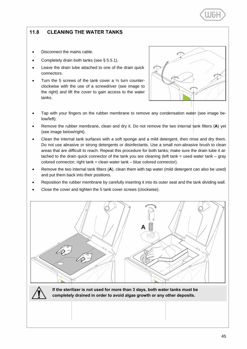
11.8 CLEANING THE WATER TANKS
• Disconnect the mains cable.
• Completely drain both tanks (see § 5.5.1).
• Leave the drain tube attached to one of the drain quick connectors.
• Turn the 5 screws of the tank cover a ½ turn counter-clockwise with the use of a screwdriver (see image to the right) and lift the cover to gain access to the water tanks.
• Tap with your fingers on the rubber membrane to remove any condensation water (see image be-low/left).
• Remove the rubber membrane, clean and dry it. Do not remove the two internal tank filters (A) yet (see image below/right).
• Clean the internal tank surfaces with a soft sponge and a mild detergent, then rinse and dry them. Do not use abrasive or strong detergents or disinfectants. Use a small non-abrasive brush to clean areas that are difficult to reach. Repeat this procedure for both tanks; make sure the drain tube it at-tached to the drain quick connector of the tank you are cleaning (left tank = used water tank – gray colored connector; right tank = clean water tank – blue colored connector).
• Remove the two internal tank filters (A), clean them with tap water (mild detergent can also be used) and put them back into their positions.
• Reposition the rubber membrane by carefully inserting it into its outer seat and the tank dividing wall.
• Close the cover and tighten the 5 tank cover screws (clockwise).
A
If the sterilizer is not used for more than 3 days, both water tanks must be completely drained in order to avoid algae growth or any other deposits.

46
11.9 REPLACING THE DOOR SEAL
• Fully open the chamber door of the sterilizer.
• Pull out the door seal by hand.
• Carefully clean the seal seat and the chamber face side with a cotton swab moistened with isopropyl alcohol.
• Moisten the new seal with water.
• Insert the seal in the sequence as illustrated in the following diagrams:
FIRST TOP
AND BOTTOM
THEN LEFT
AND RIGHT
Complete the operation by evenly inserting the seal on the entire circumference.
Make sure that the door seal is properly placed to avoid air leaks. It must be evenly in-serted on the entire circumference without any bumps or deformations.
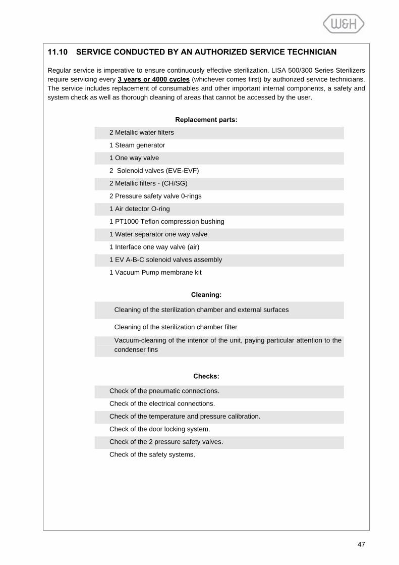
47
11.10 SERVICE CONDUCTED BY AN AUTHORIZED SERVICE TECHNICIAN
Regular service is imperative to ensure continuously effective sterilization. LISA 500/300 Series Sterilizers require servicing every 3 years or 4000 cycles (whichever comes first) by authorized service technicians. The service includes replacement of consumables and other important internal components, a safety and system check as well as thorough cleaning of areas that cannot be accessed by the user.
Replacement parts:
2 Metallic water filters
1 Steam generator
1 One way valve
2 Solenoid valves (EVE-EVF)
2 Metallic filters - (CH/SG)
2 Pressure safety valve 0-rings
1 Air detector O-ring
1 PT1000 Teflon compression bushing
1 Water separator one way valve
1 Interface one way valve (air)
1 EV A-B-C solenoid valves assembly
1 Vacuum Pump membrane kit
Cleaning:
Cleaning of the sterilization chamber and external surfaces
Cleaning of the sterilization chamber filter
Vacuum-cleaning of the interior of the unit, paying particular attention to the condenser fins
Checks:
Check of the pneumatic connections.
Check of the electrical connections.
Check of the temperature and pressure calibration.
Check of the door locking system.
Check of the 2 pressure safety valves.
Check of the safety systems.

48
12. USE OF THE MEMORY CARD (OPTIONAL FOR 300 SERIES)
LISA 500 Series Sterilizers come with a digital cycle data recording system (300 Series Sterilizers can be retrofitted on the market). Cycle data is automatically saved on removable/rewritable memory cards. Data from memory cards can be managed with your PC or MAC. Memory cards are supplied with a USB cable and an external USB reader.
Insert the memory card into the dedicated slot behind the service door until it clicks into its final position. Ensure that the flat corner of the card points to the top/right (see image below). Once a card is inserted, the unit automatically verifies the condition of the card. The verification time of the memory card takes from a few seconds to some minutes. It is possible to reduce the verification time if the card is formatted directly on the sterilizer (see § 6.7.2).
NOTE 1 Periodically transfer cycle data from the card to your computer.
NOTE 2 The manufacturer does not take responsi-bility for any damages to the memory card or loss of data during or after the warranty period.
To remove the memory card, slighty push it in and gently pull it out.
12.1 TECHNICAL CHARACTERISTICS OF THE MEMORY CARD
Technology MMC (Multi Media Card)
Tested brands that can be used with the LISA Sterilizer
*PQI-Sandisk-Lexar-Transcend-TwinMos-Toshiba
Tested capacity Between 16Mb - 256Mb
* Brands and products are trademarks of the manufacturers. The supplied memory cards have a storage capacity of not less than 64Mb.
12.2 READING OF MEMORY CARD DATA WITH A PC/MAC
Memory card data can be saved, viewed, copied and printed on a PC/MAC equipped with a USB port (USB 1.1 or above).
12.3 MINIMUM HARDWARE REQUIREMENTS FOR A PC/MAC
PC/MAC 1 free USB port (1.1 or above)
PC/MAC CD-ROM reader
PC Operating System *WINDOWS 98SE, 2000, ME, XP or above
MAC Operating System *OS 9.1.x, OS X v10.1.2+
* Brands and products are trademarks of the manufacturers.
49
12.4 CONNECTING THE EXTERNAL USB CARD READER TO YOUR PC/MAC
To connect the USB reader to your PC/MAC follow these steps: - Start the PC/MAC - Connect the USB reader to a free USB port on your computer.
NOTE 1
Most operating systems recognize the USB reader and install the device automatically. In some cases the operating system asks for the installation disk. To complete the installation follow the messages on your computer screen. For further information refer to the instruc-tions supplied with the USB reader.
NOTE 2 If the computer is connected to a network system it is possible that the USB reader drive is not visible on your computer even after correct installation. In this case consult your network administrator or assign a different drive letter to the USB reader.
Once the installation is completed and a memory card with cycle data is inserted into the external card reader, data can be saved, copied and organized on your PC/MAC.
12.5 SAVED FILE
The sterilization report is saved in a file with a HTM extension. It can be opened, viewed and printed with a HMTL viewer (e.g. *Microsoft Internet Explorer). * Brands and products are trademark of the manufacturers.
12.6 CONTROL CODE
Saved files contain a control code for proper identification. Any manipulation of a file will change the code and compromise the integrity of the saved data. W&H Sterilization will not take responsibility for any ma-nipulated cycle data.
12.7 FILE NAMES
Each cycle report is saved as a file in a HTM format. File names are generated automatically.
Example of a file name:
01898 28-01-06 08_41_22 B&D _ HELIX LISA 317 02-0005.htm
* saving format depends on the Date-Clock setting (see § 6.1.9)
12.8 DIRECTORY NAME
Files are saved on the memory card in the following structure:
LISA 317 02-0005 ∟2006-01
∟01898 28-01-06 08_41_22 B&D _ HELIX LISA 317 02-0005.htm
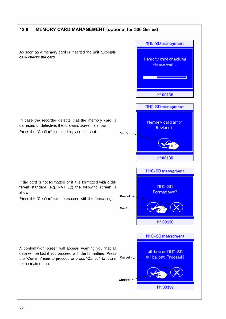
50
12.9 MEMORY CARD MANAGEMENT (optional for 300 Series)
As soon as a memory card is inserted the unit automati-cally checks the card.
In case the recorder detects that the memory card is damaged or defective, the following screen is shown. Press the “Confirm” icon and replace the card.
If the card is not formatted or if it is formatted with a dif-ferent standard (e.g. FAT 12) the following screen is shown. Press the “Confirm” icon to proceed with the formatting.
A confirmation screen will appear, warning you that all data will be lost if you proceed with the formatting. Press the “Confirm” icon to proceed or press “Cancel“ to return to the main menu.
Confirm
Confirm
Cancel
Confirm
Cancel

51
If the “Confirm” icon is pressed the formatting begins.
During formatting the system also checks for errors. If it detects any then the following screen is displayed. Press the “Confirm” icon to return to main menu and replace the card.
12.10 SAVING A FILE
If a memory card is inserted, cycle data is saved automati-cally on the card at the end of every cycle. Is no card in-serted, the following screen will be displayed. Press the “Confirm” icon to get to the cycle end screen. You always have the option to print or save data of the most recent cycle (see § 6.3).
NOTE No activity will take place if a memory card is inserted while a cycle is in progress. At the end of the cycle, the memory card will be verified and cycle data will be saved.
Confirm
Confirm
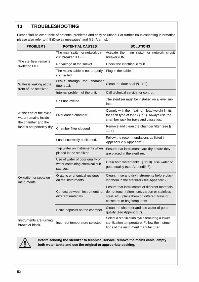
52
13. TROUBLESHOOTING
Please find below a table of potential problems and easy solutions. For further troubleshooting information please also refer to § 8 (Display messages) and § 9 (Alarms).
PROBLEMS POTENTIAL CAUSES SOLUTIONS
The main switch or network cir-cuit breaker is OFF.
Activate the main switch or network circuit breaker (ON).
No voltage at the socket. Check the electrical circuit. The sterilizer remains switched OFF.
The mains cable is not properly connected.
Plug in the cable.
Leaks through the chamber door seal. Clean the door seal (§ 11.2). Water is leaking at the
front of the sterilizer. Internal problem of the unit. Call technical service for control.
Unit not leveled. The sterilizer must be installed on a level sur-face.
Overloaded chamber. Comply with the maximum load weight limits for each type of load (§ 7.1). Always use the chamber rack for trays and cassettes.
Chamber filter clogged Remove and clean the chamber filter (see § 11.4).
At the end of the cycle, water remains inside the chamber and the load is not perfectly dry.
Load incorrectly positioned. Follow the recommendations as listed in Appendix 2 & Appendix 3.
Tap water on instruments when placed in the sterilizer.
Ensure that instruments are dry before they are placed in the sterilizer.
Use of water of poor quality or water containing chemical sub-stances.
Drain both water tanks (§ 11.8). Use water of good quality (see Appendix 7).
Organic or chemical residues on the instruments.
Clean, rinse and dry instruments before plac-ing them in the sterilizer (see Appendix 2).
Contact between instruments of different materials.
Ensure that instruments of different materials do not touch (aluminum, carbon or stainless steel. etc); place them on different trays or cassettes or bag/wrap them.
Oxidation or spots on instruments.
Scale deposits on the chamber. Clean the chamber and use water of good quality (see Appendix 7).
Instruments are turning brown or black.
Incorrect temperature selected. Select a sterilization cycle featuring a lower sterilization temperature. Follow the instruc-tions of the instrument manufacturer.
Before sending the sterilizer to technical service, remove the mains cable, empty both water tanks and use the original or appropriate packing.
53
14. RECYCLING / DISPOSAL INSTRUCTIONS
LISA 500/300 Series Sterilizers are mainly built from fiber-reinforced polymers, metals and electronic com-ponents. In case of disposal, separate the various components according to the materials they are made of. Drop the sterilizer with a company that specializes on recycling of related products. Do not abandon the sterilizer in unsecured places.
Always refer to current/applicable laws in the country of use.
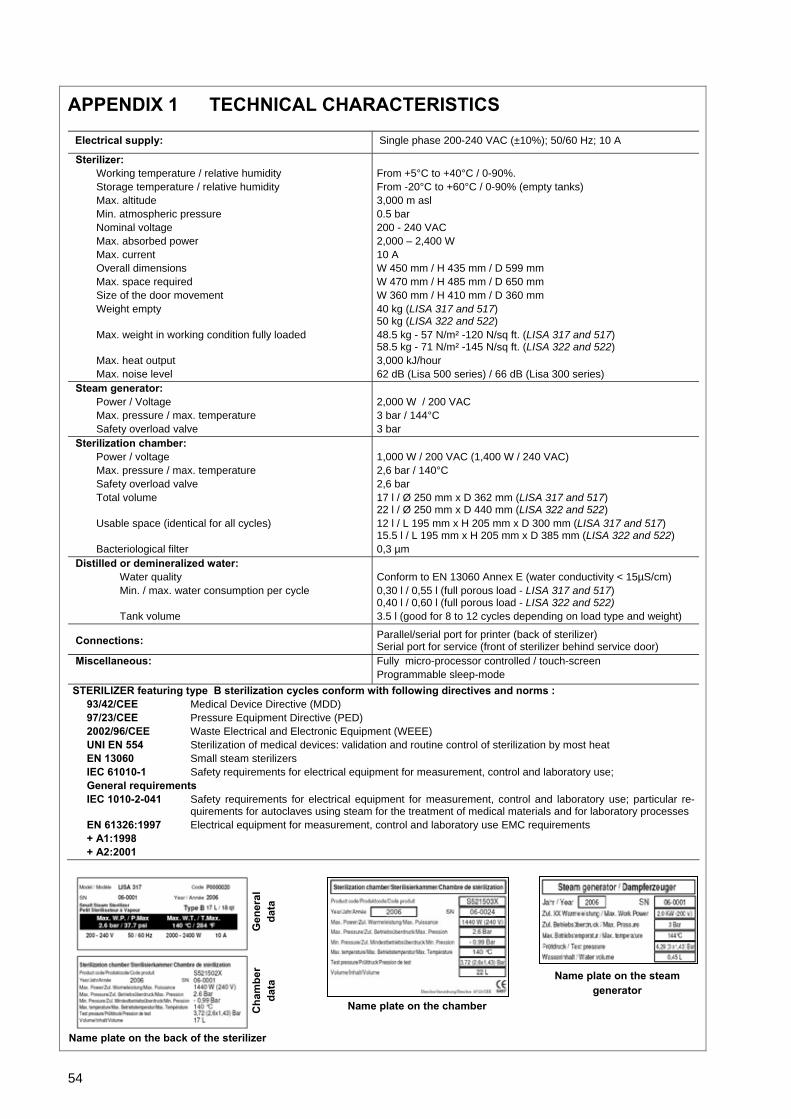
54
APPENDIX 1 TECHNICAL CHARACTERISTICS
Electrical supply: Single phase 200-240 VAC (±10%); 50/60 Hz; 10 A
Sterilizer: Working temperature / relative humidity Storage temperature / relative humidity Max. altitude Min. atmospheric pressure Nominal voltage Max. absorbed power Max. current Overall dimensions Max. space required Size of the door movement Weight empty
Max. weight in working condition fully loaded
Max. heat output Max. noise level
From +5°C to +40°C / 0-90%. From -20°C to +60°C / 0-90% (empty tanks) 3,000 m asl 0.5 bar 200 - 240 VAC 2,000 – 2,400 W 10 A W 450 mm / H 435 mm / D 599 mm W 470 mm / H 485 mm / D 650 mm W 360 mm / H 410 mm / D 360 mm 40 kg (LISA 317 and 517) 50 kg (LISA 322 and 522) 48.5 kg - 57 N/m² -120 N/sq ft. (LISA 317 and 517) 58.5 kg - 71 N/m² -145 N/sq ft. (LISA 322 and 522) 3,000 kJ/hour 62 dB (Lisa 500 series) / 66 dB (Lisa 300 series)
Steam generator: Power / Voltage Max. pressure / max. temperature Safety overload valve
2,000 W / 200 VAC 3 bar / 144°C 3 bar
Sterilization chamber: Power / voltage Max. pressure / max. temperature Safety overload valve Total volume Usable space (identical for all cycles) Bacteriological filter
1,000 W / 200 VAC (1,400 W / 240 VAC) 2,6 bar / 140°C 2,6 bar 17 l / Ø 250 mm x D 362 mm (LISA 317 and 517) 22 l / Ø 250 mm x D 440 mm (LISA 322 and 522) 12 l / L 195 mm x H 205 mm x D 300 mm (LISA 317 and 517) 15.5 l / L 195 mm x H 205 mm x D 385 mm (LISA 322 and 522) 0,3 µm
Distilled or demineralized water: Water quality Min. / max. water consumption per cycle Tank volume
Conform to EN 13060 Annex E (water conductivity < 15µS/cm) 0,30 l / 0,55 l (full porous load - LISA 317 and 517) 0,40 l / 0,60 l (full porous load - LISA 322 and 522) 3.5 l (good for 8 to 12 cycles depending on load type and weight)
Connections: Parallel/serial port for printer (back of sterilizer) Serial port for service (front of sterilizer behind service door)
Miscellaneous: Fully micro-processor controlled / touch-screen Programmable sleep-mode
STERILIZER featuring type B sterilization cycles conform with following directives and norms : 93/42/CEE Medical Device Directive (MDD) 97/23/CEE Pressure Equipment Directive (PED) 2002/96/CEE Waste Electrical and Electronic Equipment (WEEE) UNI EN 554 Sterilization of medical devices: validation and routine control of sterilization by most heat EN 13060 Small steam sterilizers IEC 61010-1 Safety requirements for electrical equipment for measurement, control and laboratory use; General requirements IEC 1010-2-041 Safety requirements for electrical equipment for measurement, control and laboratory use; particular re-
quirements for autoclaves using steam for the treatment of medical materials and for laboratory processes EN 61326:1997 Electrical equipment for measurement, control and laboratory use EMC requirements + A1:1998 + A2:2001
Gen
eral
da
ta
Name plate on the chamber
Name plate on the steamgenerator
Cha
mbe
r da
ta
Name plate on the back of the sterilizer

55
APPENDIX 2 STERILIZATION LOAD PREPARATION
1. Cleaning the instruments
The instruments to be sterilized must be clean, dry and free from any residue such as fragments,
dentine, blood, etc. These substances can damage the objects placed in the sterilizer, the sterilizer
itself and may prevent the achievement of sterile conditions of the load.
− Clean the instruments immediately after use. Follow the manufacturer’s instructions (e.g. when
using an ultrasonic cleaner).
− Remove all traces of disinfectants from the instruments as this may cause corrosion during the
sterilization process. Rinse and dry instruments thoroughly.
− Lubricate rotating instruments in accordance with the manufacturer’s instructions.
2. Preparing the trays
- For each program, do not exceed the maximum load weight limits that have been set, tested and validated by the manufacturer (see § 7.1).
− Always use the chamber rack to allow adequate steam circulation between the trays.
− Do not overload the trays.
− Leave a gap/space between sterilization bags to allow steam to circulate properly.
− Position sterilization bags with the paper side facing up.
− Empty containers or non-perforated trays must be placed upside down to prevent accumulation
of water.
− Items made from different materials (stainless steel, carbon steel, aluminum, etc.) must be
bagged or placed on separate trays.
− Where instruments are manufactured from carbon steel, paper should be placed between them
and the sterilizer tray.
− Sterilize instruments with joints (e.g. forceps, extraction pliers, etc.) in the open position.
− In the case of wrapped items, use porous packaging (e.g. sterilization bags for autoclaves) to
facilitate good steam penetration and drying. Position bags with the paper side facing up.
3. Tubes
− Rinse, drain and dry after washing.
− Place tubes on a tray allowing the ends to remain open. Do not bend tubes.
4. Wrapped / bagged material
- Leave a minimum space between the packages.
- Ensure that packages do not make contact with the steriliza-tion chamber.
- Position sterilization bags with the paper side facing up.
Paper side up
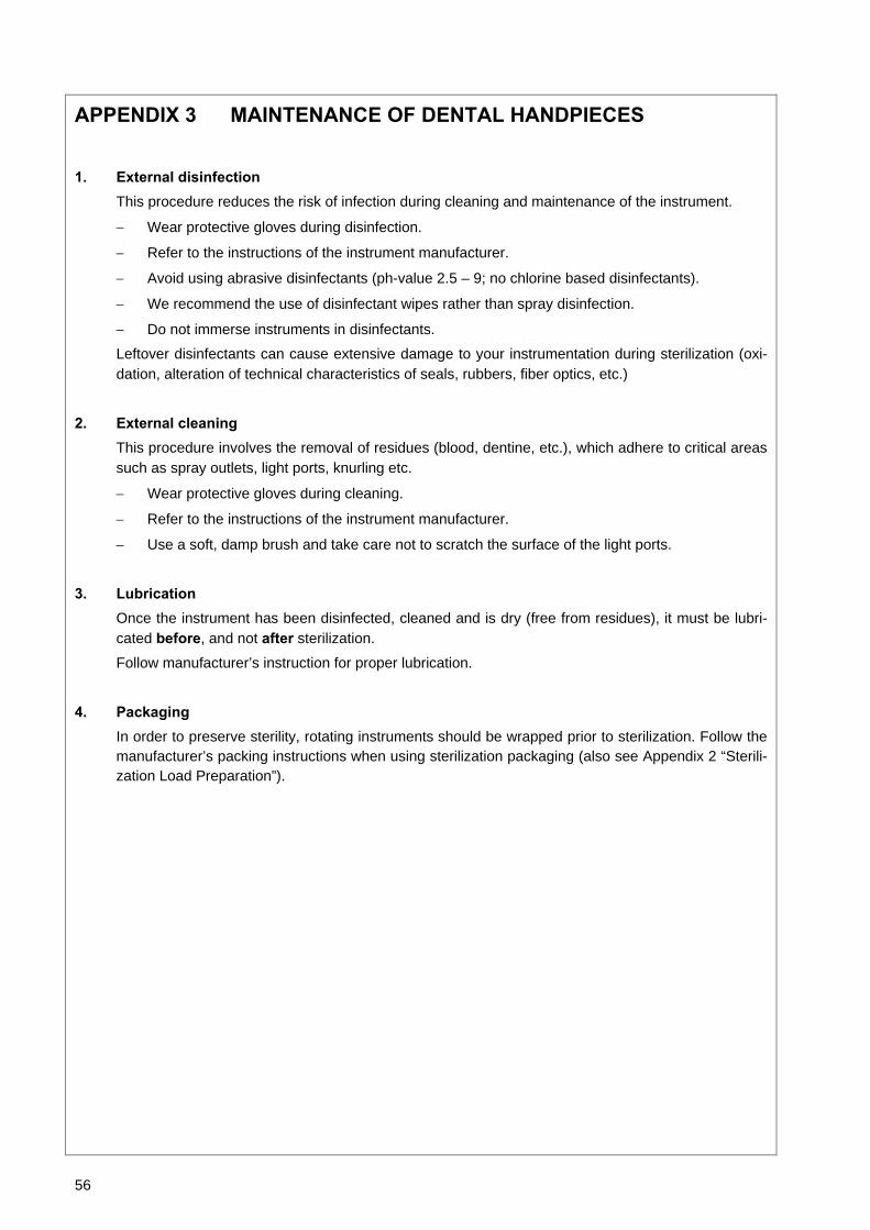
56
APPENDIX 3 MAINTENANCE OF DENTAL HANDPIECES
1. External disinfection This procedure reduces the risk of infection during cleaning and maintenance of the instrument.
− Wear protective gloves during disinfection.
− Refer to the instructions of the instrument manufacturer.
− Avoid using abrasive disinfectants (ph-value 2.5 – 9; no chlorine based disinfectants).
− We recommend the use of disinfectant wipes rather than spray disinfection.
− Do not immerse instruments in disinfectants.
Leftover disinfectants can cause extensive damage to your instrumentation during sterilization (oxi-dation, alteration of technical characteristics of seals, rubbers, fiber optics, etc.)
2. External cleaning This procedure involves the removal of residues (blood, dentine, etc.), which adhere to critical areas such as spray outlets, light ports, knurling etc.
− Wear protective gloves during cleaning.
− Refer to the instructions of the instrument manufacturer.
− Use a soft, damp brush and take care not to scratch the surface of the light ports.
3. Lubrication Once the instrument has been disinfected, cleaned and is dry (free from residues), it must be lubri-cated before, and not after sterilization.
Follow manufacturer’s instruction for proper lubrication.
4. Packaging In order to preserve sterility, rotating instruments should be wrapped prior to sterilization. Follow the manufacturer’s packing instructions when using sterilization packaging (also see Appendix 2 “Sterili-zation Load Preparation”).

57
APPENDIX 4 BOWIE & DICK TEST
The Bowie & Dick (B&D) Test, also called Steam Penetration Test, is representative of the small porous type load. It comprises several sheets of paper and foam wrapped in a small packet in the middle of which there is a chemical heat-sensitive indicator strip (physic-chemical test).
This test is used to validate the equipment performance in terms of textile load sterilization, that is:
- Pre-vacuum efficiency and thus steam pene-tration
- Temperature and pressure parameters of the saturated steam achieved during the pla-teau/holding time.
The Bowie & Dick Test cycle profile is identical to the ones of the B-UNIVERSAL 134 and the B-PRION 134 cycles with the following differences:
- The sterilization plateau is 3 minutes 20 seconds guaranteeing a 30 seconds security margin.
- The drying time is reduced to 4 min to not affect the chemical indicator result through drying.
How to carry out the test: - The test must be performed in an empty chamber (EN 13060) without load but with the standard fur-
niture (chamber rack and trays). - Place the Bowie & Dick test pack in the center of the lower tray of the chamber. - Select and start the Helix / B&D cycle from the "Test cycles" submenu.
- Once the cycle is finished, open the door and remove the test.
CAUTION: The packet will be hot! For correct interpretation of the test results, refer to the instructions of the test manufacturer.
- Remove the chemical indicator from the center of the pack. PASSED FAILED
PV3
2.16
PR LEV
End
D1
D2
DVs DVe
PV1 PP1
PP2
PPh PV2 -0.86
Pressure (Bar)
Time
All radial strips of the chemical in-
dicator have turned dark
Central part has not turned dark; e.g. due to an air pocket in the cen-
ter of the test device
The result is also incorrect, if the indicator is gray or silver (over-exposure, i.e. excessive temperature).
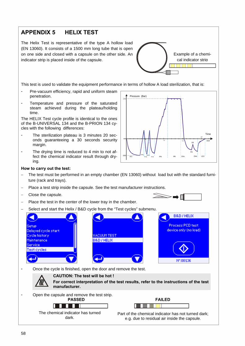
58
APPENDIX 5 HELIX TEST
The Helix Test is representative of the type A hollow load (EN 13060). It consists of a 1500 mm long tube that is open on one side and closed with a capsule on the other side. An indicator strip is placed inside of the capsule.
This test is used to validate the equipment performance in terms of hollow A load sterilization, that is:
- Pre-vacuum efficiency, rapid and uniform steam penetration.
- Temperature and pressure of the saturated steam achieved during the plateau/holding time.
The HELIX Test cycle profile is identical to the ones of the B-UNIVERSAL 134 and the B-PRION 134 cy-cles with the following differences:
- The sterilization plateau is 3 minutes 20 sec-onds guaranteeing a 30 seconds security margin.
- The drying time is reduced to 4 min to not af-fect the chemical indicator result through dry-ing.
How to carry out the test: − The test must be performed in an empty chamber (EN 13060) without load but with the standard furni-
ture (rack and trays).
− Place a test strip inside the capsule. See the test manufacturer instructions.
− Close the capsule.
− Place the test in the center of the lower tray in the chamber.
− Select and start the Helix / B&D cycle from the “Test cycles” submenu.
- Once the cycle is finished, open the door and remove the test.
CAUTION: The test will be hot ! For correct interpretation of the test results, refer to the instructions of the test manufacturer.
- Open the capsule and remove the test strip. PASSED FAILED
Example of a chemi-cal indicator strip
Part of the chemical indicator has not turned dark; e.g. due to residual air inside the capsule.
The chemical indicator has turned dark.
PV3
2.16
PR LEV
End
D1
D2
DVs DVe
PV1 PP1
PP2
PPh PV2 -0.86
Pressure (Bar)
Time
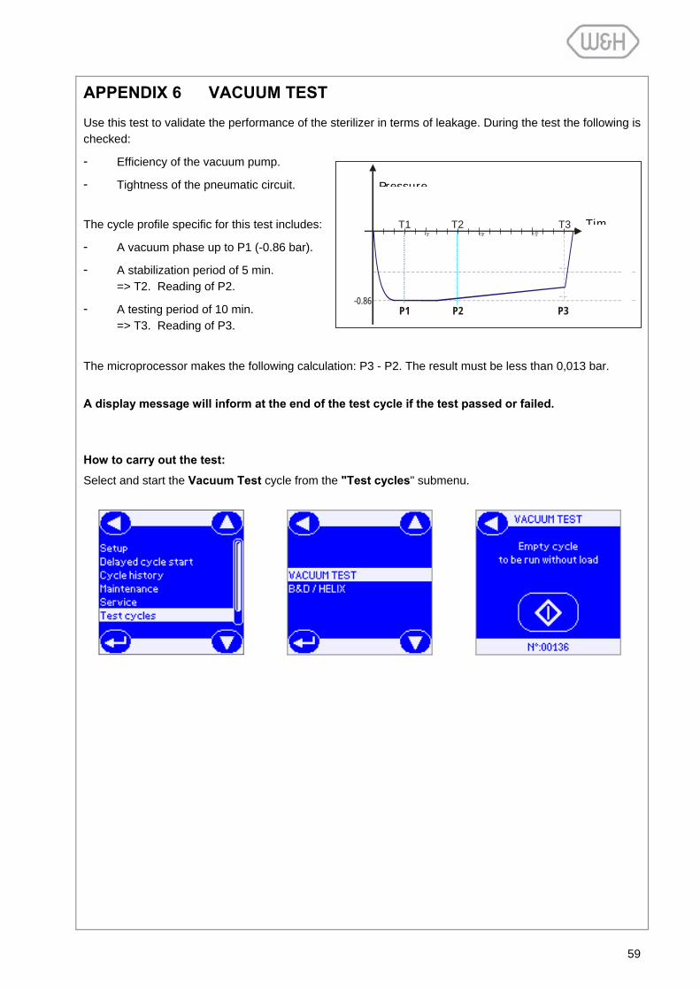
59
APPENDIX 6 VACUUM TEST
Use this test to validate the performance of the sterilizer in terms of leakage. During the test the following is checked:
- Efficiency of the vacuum pump.
- Tightness of the pneumatic circuit.
The cycle profile specific for this test includes:
- A vacuum phase up to P1 (-0.86 bar).
- A stabilization period of 5 min. => T2. Reading of P2.
- A testing period of 10 min. => T3. Reading of P3.
The microprocessor makes the following calculation: P3 - P2. The result must be less than 0,013 bar. A display message will inform at the end of the test cycle if the test passed or failed. How to carry out the test:
Select and start the Vacuum Test cycle from the "Test cycles" submenu.
T3 T2T1
P1 -0.86
P2 P3
Tim
Pressure
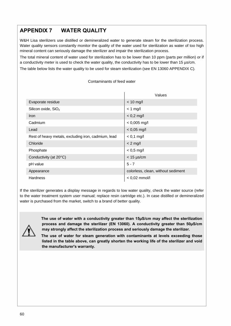
60
APPENDIX 7 WATER QUALITY
W&H Lisa sterilizers use distilled or demineralized water to generate steam for the sterilization process. Water quality sensors constantly monitor the quality of the water used for sterilization as water of too high mineral content can seriously damage the sterilizer and impair the sterilization process. The total mineral content of water used for sterilization has to be lower than 10 ppm (parts per million) or if a conductivity meter is used to check the water quality, the conductivity has to be lower than 15 µs/cm. The table below lists the water quality to be used for steam sterilization (see EN 13060 APPENDIX C).
Contaminants of feed water
Values
Evaporate residue < 10 mg/l
Silicon oxide, SiO2 < 1 mg/l
Iron < 0,2 mg/l
Cadmium < 0,005 mg/l
Lead < 0,05 mg/l
Rest of heavy metals, excluding iron, cadmium, lead < 0,1 mg/l
Chloride < 2 mg/l
Phosphate < 0,5 mg/l
Conductivity (at 20°C) < 15 µs/cm
pH value 5 - 7
Appearance colorless, clean, without sediment
Hardness < 0,02 mmol/l
If the sterilizer generates a display message in regards to low water quality, check the water source (refer to the water treatment system user manual; replace resin cartridge etc.). In case distilled or demineralized water is purchased from the market, switch to a brand of better quality.
The use of water with a conductivity greater than 15µS/cm may affect the sterilization process and damage the sterilizer (EN 13060). A conductivity greater than 50µS/cm may strongly affect the sterilization process and seriously damage the sterilizer. The use of water for steam generation with contaminants at levels exceeding those listed in the table above, can greatly shorten the working life of the sterilizer and void the manufacturer's warranty.

61
Process start (sterilization phase)
P min/max of sterilization phase
Water separator draining phase
Surgery/doctor name
Pressure pulse/heating
Sterilizer info
Cycle start date/ time
Pressure pulse
T min/max of sterilization phase
Drying phase - start
Leveling phase
Vacuum pulse
End date / time
Start condition
Cycle name
Cycle counter
Drying phase - end
Process end (sterilization phase)
APPENDIX 8 EXAMPLE OF A CYCLE DATA REPORT
LISA 517 06-5790 0.0.0.0 -------------------------------------- Dr. Smith Cycle: UNIVERSAL 134 Number: 01898 Date: 02/05/06 10:12:30 Phase Time part. T °C P Bar -------------------------------------- Start 00:00 050, +0,00 PV1 04:25 04:25 056,2 -0,85 PP1 05:05 00:40 099,8 -0,05 PV2 06:41 01:36 073,0 -0,80 PP2 07:16 00:35 100,9 +0,06 PV3 08:35 01:19 082,5 -0,80 PP3 09:09 00:34 100,7 0,05 PV4 09:45 00:36 090,2 -0,51 PPH 15:25 05:40 135,1 +2,17 -------------------------------------- PRs 15:40 00:00 135,6 +2,15 MIN 06:15 135,6 +2,15 MAX 04:45 135,7 -.- MIN 00:20 -.- +2,08 MAX 06:01 -.- +2,18 PRe 22:00 06:20 135,6 +2,17 -------------------------------------- DVs 22:00 00:00 135,6 +2,17 D01 00:00 00:00 22,0 -0,02 D02 00:00 00:00 22,0 -0,02 D03 00:00 00:00 22,0 -0,02 D04 00:00 00:00 22,0 -0,02 D05 00:00 00:00 22,0 -0,02 D06 00:00 00:00 22,0 -0,02 DVe 24:30 02:30 094,5 -0,71 SEP 25:20 00:50 095,9 -0,05 LEV 26:05 00:45 092,6 +0,00 -------------------------------------- END 26:05 0:00 092,6 +0,00 -------------------------------------- Date: 02/05/06 11:41:14 Cycle completed

62
APPENDIX 9 ACCESSORIES
DESCRIPTION ORDERING NUMBER
LisaPrint
A70010xx
Perforated anodized aluminum tray
F523204x (Lisa 317/517) F523205x (Lisa 322/522)
Chamber racks:
Chamber rack
(Europe)
190x43x300/375 *
190x43x300/375 *
190x43x300/375 *
F523008x (Lisa 317/517) F523009x (Lisa 322/522)
Chamber rack (USA)
205x35x300/375 *
205x35x300/375 *
210x35x300/375 *
F523020x (Lisa 317/517) F523021x (Lisa 322/522)
Chamber rack (for 4 cassettes)
190x32x300/375 *
210x32x300/375 *
210x32x300/375 *
190x32x300/375 *
F523012x (Lisa 317/517) F523015x (Lisa 322/522)
Chamber rack (for 2 implant cassettes)
190x70x300/375 *
190x70x300/375 *
F523016x (Lisa 317/517) F523017x (Lisa 322/522)
Tray holder
F523001x
Drain tube
S230900x
Mains cable
U38010xx
Funnel
F540903x
Bacteriological filter
W322400x
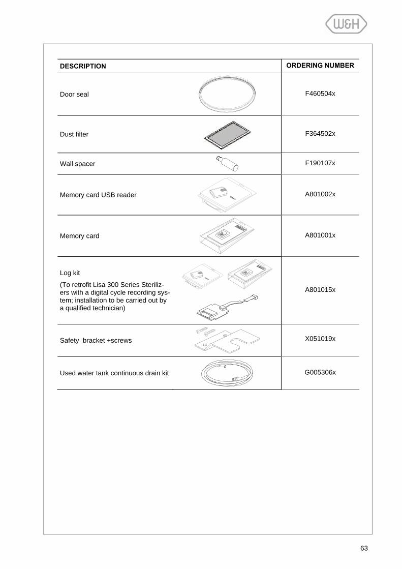
63
DESCRIPTION ORDERING NUMBER
Door seal
F460504x
Dust filter
F364502x
Wall spacer
F190107x
Memory card USB reader
A801002x
Memory card
A801001x
Log kit
(To retrofit Lisa 300 Series Steriliz-ers with a digital cycle recording sys-tem; installation to be carried out by a qualified technician)
A801015x
Safety bracket +screws
X051019x
Used water tank continuous drain kit
G005306x
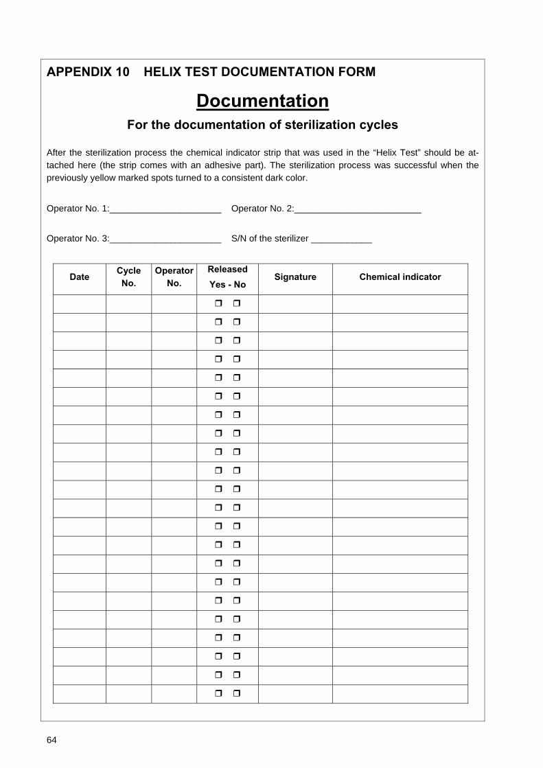
64
APPENDIX 10 HELIX TEST DOCUMENTATION FORM
Documentation For the documentation of sterilization cycles
After the sterilization process the chemical indicator strip that was used in the “Helix Test” should be at-tached here (the strip comes with an adhesive part). The sterilization process was successful when the previously yellow marked spots turned to a consistent dark color.
Operator No. 1:______________________ Operator No. 2:_________________________ Operator No. 3:______________________ S/N of the sterilizer ____________
Date Cycle No.
Operator No.
Released Yes - No
Signature Chemical indicator