user manual ark-3520p - university of wisconsin–madison · ark-3520p user manual ii attention!...
TRANSCRIPT

User Manual
ARK-3520P
Fanless Embedded Box PC

Attention!Please note:
This package contains a hard-copy user manual in Chinese for China CCC certifica-tion purposes, and there is an English user manual included as a PDF file on the CD.Please disregard the Chinese hard copy user manual if the product is not to be soldand/or installed in China.
甲類警語:
警告使用者:這是甲類資訊產品,在居住的環境使用時,可能會造成輻射干擾,在這種情況下,使用者會被要求採取某些適當措施。
ARK-3520P User Manual ii

CopyrightThe documentation and the software included with this product are copyrighted 2017by Advantech Co., Ltd. All rights are reserved. Advantech Co., Ltd. reserves the rightto make improvements in the products described in this manual at any time withoutnotice.
No part of this manual may be reproduced, copied, translated or transmitted in anyform or by any means without the prior written permission of Advantech Co., Ltd.Information provided in this manual is intended to be accurate and reliable. However,Advantech Co., Ltd. assumes no responsibility for its use, nor for any infringementsof the rights of third parties, which may result from its use.
AcknowledgementsAward is a trademark of Award Software International, Inc.
VIA is a trademark of VIA Technologies, Inc.
IBM, PC/AT, PS/2 and VGA are trademarks of International Business Machines Cor-poration.
Intel® and Pentium® are trademarks of Intel Corporation.
Microsoft Windows® is a registered trademark of Microsoft Corp.
RTL is a trademark of Realtek Semi-Conductor Co., Ltd.
ESS is a trademark of ESS Technology, Inc.
UMC is a trademark of United Microelectronics Corporation.
SMI is a trademark of Silicon Motion, Inc.
Creative is a trademark of Creative Technology LTD.
CHRONTEL is a trademark of Chrontel Inc.
All other product names or trademarks are properties of their respective owners.
For more information about this and other Advantech products, please visit our web-site at:
http://www.advantech.com/
http://www.advantech.com/ePlatform/
For technical support and service, please visit our support website at:
http://support.advantech.com.tw/support/
Part No. 2006R35200 Edition 1
Printed in China April 2017
iii ARK-3520P User Manual

Product Warranty (2 years)Advantech warrants to you, the original purchaser, that each of its products will befree from defects in materials and workmanship for two years from the date of pur-chase.
This warranty does not apply to any products which have been repaired or altered bypersons other than repair personnel authorized by Advantech, or which have beensubject to misuse, abuse, accident or improper installation. Advantech assumes noliability under the terms of this warranty as a consequence of such events.
Because of Advantech’s high quality-control standards and rigorous testing, most ofour customers never need to use our repair service. If an Advantech product is defec-tive, it will be repaired or replaced at no charge during the warranty period. For out-of-warranty repairs, you will be billed according to the cost of replacement materials,service time and freight. Please consult your dealer for more details.
If you think you have a defective product, follow these steps:
1. Collect all the information about the problem encountered. (For example, CPU speed, Advantech products used, other hardware and software used, etc.) Note anything abnormal and list any onscreen messages you get when the problem occurs.
2. Call your dealer and describe the problem. Please have your manual, product, and any helpful information readily available.
3. If your product is diagnosed as defective, obtain an RMA (return merchandise authorization) number from your dealer. This allows us to process your return more quickly.
4. Carefully pack the defective product, a fully-completed Repair and Replacement Order Card and a photocopy proof of purchase date (such as your sales receipt) in a shippable container. A product returned without proof of the purchase date is not eligible for warranty service.
5. Write the RMA number visibly on the outside of the package and ship it prepaid to your dealer.
Declaration of Conformity
FCC Class A
Note: This equipment has been tested and found to comply with the limits for a ClassA digital device, pursuant to part 15 of the FCC Rules. These limits are designed toprovide reasonable protection against harmful interference when the equipment isoperated in a commercial environment. This equipment generates, uses, and canradiate radio frequency energy and, if not installed and used in accordance with theinstruction manual, may cause harmful interference to radio communications. Opera-tion of this equipment in a residential area is likely to cause harmful interference inwhich case the user will be required to correct the interference at his own expense.
ARK-3520P User Manual iv

Technical Support and Assistance1. Visit the Advantech web site at www.advantech.com/support where you can find
the latest information about the product.2. Contact your distributor, sales representative, or Advantech's customer service
center for technical support if you need additional assistance. Please have the following information ready before you call:– Product name and serial number– Description of your peripheral attachments– Description of your software (operating system, version, application software,
etc.)– A complete description of the problem– The exact wording of any error messages
Warnings, Cautions and Notes
Packing ListBefore installation, please ensure the following items have been shipped:
1 x ARK-3520 Unit 1 x Registration and 2 years Warranty Card 1 x Simplied Chinese Manual 1 x China RoHs 1 x 4 pin DC in terminal block 1 x 2 pin power on/off terminal block
Warning! Warnings indicate conditions, which if not observed, can cause personal injury!
Caution! Cautions are included to help you avoid damaging hardware or losing data. e.g.
There is a danger of a new battery exploding if it is incorrectly installed. Do not attempt to recharge, force open, or heat the battery. Replace the battery only with the same or equivalent type recommended by the man-ufacturer. Discard used batteries according to the manufacturer's instructions.
Note! Notes provide optional additional information.
v ARK-3520P User Manual

Ordering Information
Optional Accessories
Model Number Description
ARK-3520P-U8A1E Intel 6th Gen. Core i (I7-6820EQ) High Performance Fanless Embedded BOX PC with 2 x PCI
ARK-3520P-U7A1E Intel 6th Gen. Core i (I5-6440EQ) High Performance Fanless Embedded BOX PC with 2 x PCIe x 4
Part Number Description
96PSA-A150W19P4-1 AC-to-DC Adapter, DC19V 150W
96PSA-A220W24P4-1 AC-to DC adapter, DC24V 220W
1702002600 Power cable 3-pin 183cm, USA type
1702002605 Power cable 3-pin 183cm, EU type
1702031801 Power cable 3-pin 183cm, UK type
1700000237 Power Cord, 3-Pin 183cm, PSE
ARK-3520P User Manual vi

Safety Instructions1. Please read these safety instructions carefully.2. Please keep this User’s Manual for later reference.3. Please disconnect this equipment from AC outlet before cleaning. Use a damp
cloth. Don’t use liquid or sprayed detergent for cleaning. Use moisture sheet or clothe for cleaning.
4. For pluggable equipment, the socket-outlet shall near the equipment and shall be easily accessible.
5. Please keep this equipment from humidity.6. Lay this equipment on a reliable surface when install. A drop or fall could cause
injury.7. The openings on the enclosure are for air convection hence protecting the
equipment from overheating. DO NOT COVER THE OPENINGS.8. Make sure the voltage of the power source when connecting the equipment to
the power outlet.9. Place the power cord such a way that people cannot step on it. Do not place
anything over the power cord. 10. All cautions and warnings on the equipment should be noted.11. If the equipment is not used for long time, disconnect the equipment from mains
to avoid being damaged by transient over-voltage.12. Never pour any liquid into ventilation openings; this could cause fire or electrical
shock.13. Never open the equipment. For safety reasons, only qualified service personnel
should open the equipment.14. If one of the following situations arises, get the equipment checked by service
personnel:The power cord or plug is damaged.Liquid has penetrated into the equipment.The equipment has been exposed to moisture.The equipment does not work well, or you cannot get it to work according to
the user's manual.The equipment has been dropped and damaged.The equipment has obvious signs of breakage.
15. Do not leave this equipment in an environment where the storage temperature may go below -40° C (-40° F) or above 85° C (185° F). This could damage the equipment. the equipment should be in a controlled environment.
16. Caution: Danger of explosion if battery is incorrectly replaced. Replace only with the same or equivalent type recommended by the manufacturer, discard used batteries according to the manufacturer's instructions.
17. The sound pressure level at the operator's position according to IEC 704-1:1982 is no more than 70 dB (A).
18. RESTRICTED ACCESS AREA: The equipment should only be installed in a Restricted Access Area.
19. DISCLAIMER: This set of instructions is given according to IEC 704-1. Advan-tech disclaims all responsibility for the accuracy of any statements contained herein.
vii ARK-3520P User Manual

ARK-3520P User Manual viii

Contents
Chapter 1 General Introduction ...........................11.1 Introduction ............................................................................................... 21.2 Product Features....................................................................................... 3
1.2.1 General ......................................................................................... 31.2.2 Display .......................................................................................... 31.2.3 Ethernet ........................................................................................ 3
1.3 Chipset ...................................................................................................... 41.3.1 Functional Specification ................................................................ 41.3.2 SUSI 4.0........................................................................................ 5
1.4 Mechanical Specifications......................................................................... 61.4.1 Dimensions ................................................................................... 6
Figure 1.1 ARK-3520P Mechanical dimension drawing .............. 61.4.2 Weight........................................................................................... 6
1.5 Power Requirement .................................................................................. 61.5.1 System Power............................................................................... 61.5.2 RTC Battery .................................................................................. 6
1.6 Environment Specification......................................................................... 71.6.1 Operating Temperature................................................................. 71.6.2 Relative Humidity .......................................................................... 71.6.3 Storage Temperature.................................................................... 71.6.4 Vibration during Operation ............................................................ 71.6.5 Shock during Operation ................................................................ 71.6.6 Safety............................................................................................ 71.6.7 EMC.............................................................................................. 7
Chapter 2 Hardware Configuration......................92.1 Introduction ............................................................................................. 102.2 Jumpers .................................................................................................. 10
2.2.1 Jumper Description ..................................................................... 102.2.2 Jumper List ................................................................................. 10
Table 2.1: Jumper List ............................................................... 102.2.3 Jumper Locations........................................................................ 11
Figure 2.1 Jumper Layout.......................................................... 112.2.4 Jumper Settings .......................................................................... 112.2.5 Jumper Setting............................................................................ 122.2.6 Jumper Setting............................................................................ 13
2.3 Connectors.............................................................................................. 142.3.1 ARK-3520P External I/O Locations............................................. 14
Figure 2.2 ARK-3520 Front IO connector drawing .................... 14Figure 2.3 ARK-3520 Rear IO connector drawing ..................... 14
2.3.2 ARK-3520P Front I/O Connectors .............................................. 15Figure 2.4 USB2.0 connector .................................................... 15Table 2.2: USB 2.0 Connector Pin Assignments....................... 15Figure 2.5 COM connector ........................................................ 15Table 2.3: COM Connector Pin Assignments............................ 15Figure 2.6 Power Input Connector............................................. 16Table 2.4: Power Input Connector Pin Assignments ................. 16Figure 2.7 Ethernet connector ................................................... 16Table 2.5: Ethernet Connector Pin Assignments....................... 16
2.3.3 ARK-3520 Rear I/O Connectors ................................................. 17Figure 2.8 Power ON/OFF Button ............................................. 17Figure 2.9 Audio Connector....................................................... 17Table 2.6: Audio Connector Pin Assignments ........................... 17
ix ARK-3520P User Manual

Figure 2.10DIO Connector ......................................................... 18Table 2.7: DIO Connector Pin Assignments.............................. 18Figure 2.11LED Indicators.......................................................... 18Figure 2.12HDMI receptacle connector...................................... 19Table 2.8: HDMI Connector Pin Assignments........................... 19Figure 2.13USB3.0 Connector ................................................... 19Table 2.9: USB 3.0 Connector Pin Assignments....................... 19Figure 2.14VGA Connector ........................................................ 20Table 2.10:VGA Connector Pin Assignments ............................ 20Figure 2.15Power Switch............................................................ 20Table 2.11:Power Switch Connector Pin Assignments .............. 20
2.4 Installation............................................................................................... 212.4.1 Memory Installation..................................................................... 212.4.2 HDD/SSD Installation ................................................................. 212.4.3 Remove Bottom Cover ............................................................... 222.4.4 Remove Riser Card Bracket ....................................................... 222.4.5 M.2 Module/MiniPCIe Module/Internal SIM Card Slot Installation ..
232.4.6 Riser Card Installation ................................................................ 232.4.7 Remove HDD Bracket ................................................................ 242.4.8 iDoor Installation ......................................................................... 252.4.9 Optional Module for Third Display Installation ............................ 252.4.10 Replace CPU thermal Grease Pad............................................. 262.4.11 Wide operating temperature support .......................................... 26
Chapter 3 BIOS Settings .................................... 273.1 Introduction ............................................................................................. 283.2 Entering Setup ........................................................................................ 29
3.2.1 Main Setup.................................................................................. 293.2.2 Advanced BIOS Features Setup................................................. 303.2.3 Chipset Configuration ................................................................. 483.2.4 Security....................................................................................... 583.2.5 Boot ............................................................................................ 593.2.6 Save & Exit ................................................................................. 60
Appendix A Watchdog Timer Sample Code ........ 61A.1 EC Watchdog Timer Sample Code......................................................... 62
Appendix B USB 3.0 Drivers Installation Instruction65
B.1 USB 3.0 Drivers Installation Instruction .................................................. 66
ARK-3520P User Manual x

Chapter 1
1 General IntroductionThis chapter gives background information on ARK-3520P series.
1.1 IntroductionARK-3520, an Intelligent, high performance, fanless embedded system powered byIntel 6th Core i3,i5.i7 BGA processor comes with rich I/O combination and Expansionsolution. The expansion are supported by either riser card(PCI/PCIex4)
ARK-3520 Core i7 CPU performance has over 50% increased compared with ARK-3500 and over 200% increased in graphics. ARK-3520 offers independent triple dis-plays: VGA, HDMI and 3rd optional display port. It also provides 8 x COMs, 2 x GbE,6 x USB 3.0, 2 x USB2.0, 2 x Mini PCIe (1 shared with mSATA), 2 x 2.5" SATAIII stor-age devices, and 1 16 bits DIO port.
Rugged & Multifunctional Design
ARK-3520 adopts advanced thermal design for HDD and power enhancement. Allmodels are fanless, and highlight various quality features including wide-input powersupplies from 9V to 36V, wide temperature range from -20~60° C, diverse expand-ability options and structural strengthening. ARK-3520 adopt the unique thermal solu-tion which allow Onboard 6th Core i CPU working efficient and smoothly. It alsoprovides rich I/O interfaces: up to 2 x Intel GbE, 6 x USB 3.0, 2 x USB 2.0,2 x 2.5”HDD, 1 x mSATA, 4 x RS-232 and 4 x RS-232/422/485 COM ports.
Various Expansion Support
ARK-3520 is a flexible model which can work in different environment and applica-tions with multiple I/O and high performance. It can support two kinds of riser cards: 2x PCI or 2 x PCIe x 4. It also has board-to-board design and more I/O ports in coastline without cables.
Built in Intelligent Management Tools - Advantech iManager & WISE-PaaS/RMM
Advantech iManager provides a valuable suite of programmable APIs such as multi-level watchdog, hardware monitor, system restore, and other user-friendly interface.
iManager is an intelligent self-management cross platform tool that monitors systemstatus for problems and takes action if anything is abnormal. iManager offers a bootup guarantee in critical, low temperature environments so systems can automaticallyrecover when voltages dip. iManager makes the whole system more reliable andmore intelligent. ARK-3520 also supports Advantech’s own WISE-PaaS/RMM, whichprovides easy remote management so users can monitor, configure, and control alarge number of terminals to make maintenance and system recovery simpler.
ARK-3520P User Manual 2

Chapter 1
GeneralIntroduction
1.2 Product Features
1.2.1 General CPU: Intel ® 6th Gen Core i3/i5/i7 BGA processor ( up to 45W) System Chipset: Intel QM170 BIOS: AMI EFI 128-Mbit SPI Flash BIOS System Memory: DDR4 2133Mhz up to 32GB Watchdog Timer: Single chip Watchdog 255-level interval timer, setup by soft-
ware I/O Interface:
– 4 x RS232, 4 x RS232/422/485– COM 1, 2 support 5V/12V power supply(by jumper)
USB: – 6 x USB 3.0 and 2 x USB 2.0 compliant ports
Audio: High Definition Audio (HD), Line out, Mic-in Storage: 2 x 2.5" removable HDD drive bays (15 mm height) and 1 x mSATA Expansion Interface:
– 2 x Full size MiniPCIe (1 support mSATA and 1 with SIM holder)– 1 x iDoor– 2 x PCI / 2x PCIex4– 1 x M.2 (E key for Wifi)
Software API: Advantech iManager and WISE-PaaS/RMM - Remote Device Management technology
1.2.2 Display Controller: Intel® HD Graphic 530 Resolution:
– VGA: support 1920x1200 @ 60 Hz– HDMI: Support HDMI 1.4b, 3840 x 2160 @ 30 Hz– Display Port: 2560 x 1600 @ 60Hz (Video only, and only support with 3rd
gen. processor) Triple Display:
– VGA + HDMI + 3rd Optional display module
1.2.3 Ethernet Chipset:
– LAN1 Intel® i219LM – LAN2 Intel® i210IT
Speed: 10/100/1000 Mbps Interface: 2 x RJ45
3 ARK-3520P User Manual
1.3 Chipset
1.3.1 Functional Specification
1.3.1.1 Processor
1.3.1.2 Chipset
1.3.1.3 Others
Processor
Supports BGA processor (up to 45W): Intel® Core™ i7-6820EQ 2.8GHz with 8M L3 cache Intel® Core™ i5-6440EQ 2.7GHz with 6M L3 cache Intel® Core™ i3-6100E 2.7GHz with 3M L3 cache
Memory Supports DDR4 2133 MHz up to 32GB2 x 260-pin SODIMM socket type
Internal Graphics Features
Direct x 12, OpenGL 4.4 VGA + HDMI + 3rd optional display module Supports HDCP 1.4b Intel® Display Power saving technology 6.0
Video Accelerator
HW accelerated Media Decode: H.265/HEVC, H.264/MPEG-4 AVC, MPEG-2, VC-1/WMV9, JPEG/MJPEG, VP8 and VP9
HW accelerated Media Encode:H. H.265/HEVC, H.264/MPEG-4 AVC, MPEG-2, JPEG/MJPEG and VP8
SATA Interface
Intel QM170 chip supports: Supports several optional sections of Serial ATA niaIII Supports SATA Data Transfer Rates up to 6 Gb/s Integrated AHCI controller Supports mSATA socket
USB Interface
Intel QM170 chip supports: 1 x EHCI Host Controller, supporting SuperSpeed USB 3.0 ports 1 x XHCI Host Controllers, supporting HighSpeed USB 2.0 ports Supports wake-up from sleeping states S3–S4 Maximum 500mA for each USB port
Power Management
Intel QM170 chip supports: Supports ACPI ACPI-defined power states (processor driven C states) ACPI Power Management Timer SMI# generation
BIOSIntel QM170 chip supports: AMI 128-Mbit EFI Flash BIOS via SPI
Serial ports
Up to 8 serial ports. Supports IRQ Sharing among serial ports under Microsoft
Windows OS COM1,COM2,COM3,COM4: RS-232/422/485 COM5,COM6,COM7,COM8: RS-232
Ethernet
LAN1 Intel i219LM, LAN2 Intel i210 IT
Supports 10/100/1000 Mbps. LAN Connectors: Phone Jack RJ45 8P 90D(F)
ARK-3520P User Manual 4

Chapter 1
GeneralIntroduction
1.3.2 SUSI 4.0
Audio
Audio Codec: ALC888S-VD2-GR
Compliant with HD Audio specifications Supports 16/20/24-bit DAC and 16/20/24-bit ADC resolution Supports: Speak-out, Mic-in Audio Connectors: Ear Phone Jack * 2
Battery backup BATTERY 3V/210 mAh with WIRE x 1
iManager
Sequence control Supported
DIO 16-bit programmable DIO
Watchdog timer Multi-level WDT (set by Advantech iManager)Programmable 1-255 sec / min
Hardware monitor CPU Temperature / input Current / input Voltage
System information Running HR / Boot record
5 ARK-3520P User Manual

1.4 Mechanical Specifications
1.4.1 Dimensions220[8.66] x 101 [3.98] x 233 [9.17] (Unit: mm [Inch})
Figure 1.1 ARK-3520P Mechanical dimension drawing
1.4.2 Weight4.4 kg (9.7 lb)
1.5 Power Requirement
1.5.1 System Power Minimum power input:
– ARK-3520P: 9 ~ 36V (16.65 ~ 4.16 A)
1.5.2 RTC Battery Lithium 3 V/210 mAH
ARK-3520P User Manual 6
Chapter 1
GeneralIntroduction
1.6 Environment Specification
1.6.1 Operating Temperature With Industrial Grade SSD: -20~60° C (-4 ~ 140° F), with air flow, speed=0.7
m/sec With 2.5-inch hard disk: 0 to 40° C (32 ~ 104° F), with air flow, speed=0.7 m/
sec
1.6.2 Relative Humidity 95% @ 40° C (non-condensing)
1.6.3 Storage Temperature -40 ~ 85° C (-40 ~ 185° F)
1.6.4 Vibration during Operation For system equipped with SSD/mSATA: 3Grms, IEC 60068-2-64, random, 5 ~
500 Hz
1.6.5 Shock during Operation For system equipped with SSD/mSATA: 30G, IEC 60068-2-27, half sin, 11 ms
duration
1.6.6 Safety LVD, CCC, BSMI
1.6.7 EMC CE, FCC, CCC, BSMI
7 ARK-3520P User Manual

ARK-3520P User Manual 8

Chapter 2
2 Hardware Configuration
2.1 IntroductionThe following sections show the internal jumpers setting and the external connectorspin assignment for application.
2.2 Jumpers
2.2.1 Jumper DescriptionYou may configure ARK-3520P to match the needs of your application by settingjumpers. A jumper is a metal bridge used to close an electric circuit. It consists of twometal pins and a small metal clip (often protected by a plastic cover) that slides overthe pins to connect them. To close a jumper, you connect the pins with the clip. Toopen a jumper, you remove the clip. Sometimes a jumper will have three pins,labeled 1, 2 and 3. In this case you would connect either pins 1 and 2, or 2 and 3.
The jumper settings are schematically depicted in this manual as follows.
A pair of needle-nose pliers may be helpful when working with jumpers. If you haveany doubts about the best hardware configuration for your application, contact yourlocal distributor or sales representative before you make any changes. Generally, yousimply need a standard cable to make most connections.
2.2.2 Jumper List
closed 2-3closedopen
1 2 1 2
closed 2-3closedopen
Table 2.1: Jumper List J1 Auto Power On Setting
J2 mSATA/PCIe Setting
CN4 COM2 RS-232 Power Setting
CN6 COM1 RS-232 Power Setting
JM1 PCI CLK SELECT setting
ARK-3520P User Manual 10

Chapter 2
Hardw
areC
onfiguration
2.2.3 Jumper Locations
Figure 2.1 Jumper Layout
2.2.4 Jumper SettingsOn Motherboard
2.2.4.1 Auto Power on Setting (J1)
2.2.4.2 mSATA / PCIe Setting (J2)
J1 Auto Power on Setting
Part Number 1653002101-02
Footprint HD_2x1P_79_D
Description
Setting Function
NC Power Button for Power On (Default)
(1-2) Auto Power On
J2 mSATA / PCIe Setting
Part Number 1653003101
Footprint HD_2x1P_79_D
Description PIN HEADER 2x1P 2.0mm 180D(M) DIP 21N12050
Setting Function
(1-2) mSATA
(2-3) PCIe (Default)
11 ARK-3520P User Manual

2.2.5 Jumper Setting Jumper setting of IO board of AMO-M016:
2.2.5.1 COM2 RS232 Power Setting (CN4) on AMO-M016* Please check CN6 on AMO-M016 for COM1 RS-232 setting as well
2.2.5.2 COM1 RS232 Power Setting (CN6) on AMO-M016
CN4 PH_3x2V_S2.00mm
Part Number 1653003201
Footprint HD_3x2P_79_D
Description
Setting Function
(1-2) Normal (default)
(3-4) +5V
(5-6) +12V
4
5
3
6
1 2
CN6 PH_3x2V_S2.00mm
Part Number 1653003201
Footprint HD_3x2P_79_D
Description
Setting Function
(1-2) Normal (default)
(3-4) +5V
(5-6) +12V
4
5
3
6
1 2
ARK-3520P User Manual 12

Chapter 2
Hardw
areC
onfiguration
2.2.6 Jumper SettingRiser card - AMO-R023 jumper setting:
2.2.6.1 AMO-R023 PCI CLK SELECT Setting
JM1 PH 3 x1P 2.54mm
Part Number 1653003100
Footprint HD_3x1P_100_D
Setting Function
(1-2) 66 MHz
(2-3) 33 MHz (Default)
13 ARK-3520P User Manual

2.3 Connectors
2.3.1 ARK-3520P External I/O LocationsARK-3520 Front IO Panel
Figure 2.2 ARK-3520 Front IO connector drawing
ARK-3520 Rear IO Panel
Figure 2.3 ARK-3520 Rear IO connector drawing
ARK-3520P User Manual 14
Chapter 2
Hardw
areC
onfiguration
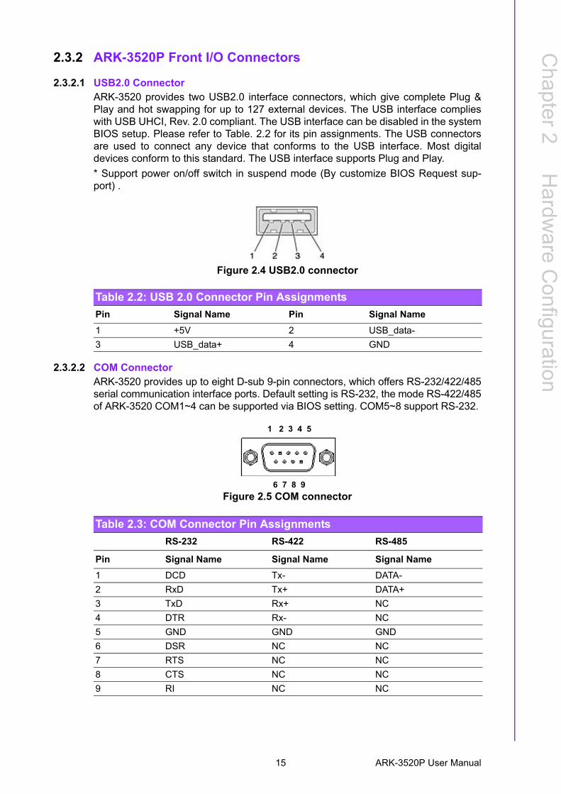
2.3.2 ARK-3520P Front I/O Connectors
2.3.2.1 USB2.0 ConnectorARK-3520 provides two USB2.0 interface connectors, which give complete Plug &Play and hot swapping for up to 127 external devices. The USB interface complieswith USB UHCI, Rev. 2.0 compliant. The USB interface can be disabled in the systemBIOS setup. Please refer to Table. 2.2 for its pin assignments. The USB connectorsare used to connect any device that conforms to the USB interface. Most digitaldevices conform to this standard. The USB interface supports Plug and Play.
* Support power on/off switch in suspend mode (By customize BIOS Request sup-port) .
Figure 2.4 USB2.0 connector
2.3.2.2 COM ConnectorARK-3520 provides up to eight D-sub 9-pin connectors, which offers RS-232/422/485serial communication interface ports. Default setting is RS-232, the mode RS-422/485of ARK-3520 COM1~4 can be supported via BIOS setting. COM5~8 support RS-232.
Figure 2.5 COM connector
Table 2.2: USB 2.0 Connector Pin Assignments
Pin Signal Name Pin Signal Name
1 +5V 2 USB_data-
3 USB_data+ 4 GND
Table 2.3: COM Connector Pin Assignments
RS-232 RS-422 RS-485
Pin Signal Name Signal Name Signal Name
1 DCD Tx- DATA-
2 RxD Tx+ DATA+
3 TxD Rx+ NC
4 DTR Rx- NC
5 GND GND GND
6 DSR NC NC
7 RTS NC NC
8 CTS NC NC
9 RI NC NC
1 2 3 4 5
6 7 8 9
15 ARK-3520P User Manual

2.3.2.3 Power Input ConnectorARK-3520P provides a 4-pin connector, which supports 9 ~ 36 VDC external powerinput. Please refer to Table. 2.4 for its pin assignments.
Figure 2.6 Power Input Connector
2.3.2.4 Ethernet Connector (LAN)ARK-3520 is equipped with 2 Ethernet controllers that are fully compliant with IEEE802.3u 10/100/1000 Mbps CSMA/CD standards. The Ethernet port provides a stan-dard RJ-45 jack connector with LED indicators on the front side to show its Active/Link status (Green LED) and Speed status (Yellow LED).
Figure 2.7 Ethernet connector
Note! NC represents “No Connection”.
Table 2.4: Power Input Connector Pin Assignments
Pin Signal Name
1 GND
2 +9 ~ 36 VDC
3 +9 ~ 36 VDC
4 GND
Table 2.5: Ethernet Connector Pin Assignments
Pin 10/100/1000BaseT Signal Name
1 TX+
2 TX-
3 RX+
4 MDI2+
5 MDI2-
6 RX-
7 MDI3+
8 MDI3-
18
ARK-3520P User Manual 16

Chapter 2
Hardw
areC
onfiguration
2.3.3 ARK-3520 Rear I/O Connectors
2.3.3.1 Power On/Off ButtonARK-3520 has a Power On/Off button with LED indicators on the front side that showOn status (Green LED) and Off/Suspend status (Orange LED). The Power buttonsupports dual functions: Soft Power -On/Off (Instant off or Delay 4 Seconds then off),and Suspend.
Figure 2.8 Power ON/OFF Button
2.3.3.2 Audio ConnectorARK-3520 offers two stereo audio ports: Line_Out, Mic_In.
Figure 2.9 Audio Connector
Table 2.6: Audio Connector Pin Assignments
Pin Audio Signal Name
1 Line out
2 Mic in
17 ARK-3520P User Manual

2.3.3.3 DIO Connector
Figure 2.10 DIO Connector
2.3.3.4 LED IndicatorsThere are two LEDs on the front panel that indicate system status: The thermal LEDis for system thermal alarm status; and HDD LED is for HDD status.
Figure 2.11 LED Indicators
Table 2.7: DIO Connector Pin Assignments
Pin Signal Name Pin Signal Name
1 GND 14 GND
2 Port0 D0 15 Port1 D0
3 Port0 D1 16 Port1 D1
4 Port0 D2 17 Port1 D2
5 Port0 D3 18 Port1 D3
6 Port0 D4 19 Port1 D4
7 Port0 D5 20 Port1 D5
8 Port0 D6 21 Port1 D6
9 Port0 D7 22 Port1 D7
10 +5V 23 +5V
11 NC 24 NC
12 NC 25 NC
13 NC
Note! NC represents “No Connection”.
ARK-3520P User Manual 18

Chapter 2
Hardw
areC
onfiguration
2.3.3.5 HDMI ConnectorAn integrated, 19-pin receptacle connector HDMI Type A Interface is provided. TheHDMI link supports resolutions up to 1920 x 1200 @ 30 Hz.
Figure 2.12 HDMI receptacle connector
2.3.3.6 USB3.0 ConnectorARK-3520 supports six USB 3.0 interfaces. The USB interfaces complies with USBUHCI, Rev. 3.0 standards. Please refer to Table 2.9 for its pin assignments. USB 3.0connectors contain legacy pins to interface to USB 2.0 devices, and a new set of pinsfor USB 3.0 connectivity.
Figure 2.13 USB3.0 Connector
Table 2.8: HDMI Connector Pin Assignments
Pin Signal Name Pin Signal Name
1 TMDS Data 2+ 2 TMDS Data 2 shield
3 TMDS Data 2- 4 TMDS Data 1+
5 TMDS Data 1 shield 6 TMDS Data 1-
7 TMDS Data 0+ 8 TMDS Data 0 shield
9 TMDS Data 0- 10 TMDS clock+
11 TMDS clock shield 12 TMDS clock-
13 CEC 14 Reserved
15 SCL 16 SDA
17 DDC/CEC Ground 18 +5V
19 Hot Plug Detect
Table 2.9: USB 3.0 Connector Pin Assignments
Pin Signal Name Pin Signal Name
1 +5V 2 USB_data-
3 USB_data+ 4 GND
5 SSRX- 6 SSRX+
7 GND 8 SSTX-
9 SSTX+
19 ARK-3520P User Manual
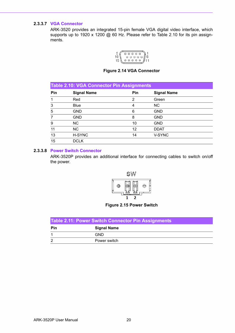
2.3.3.7 VGA ConnectorARK-3520 provides an integrated 15-pin female VGA digital video interface, whichsupports up to 1920 x 1200 @ 60 Hz. Please refer to Table 2.10 for its pin assign-ments.
Figure 2.14 VGA Connector
2.3.3.8 Power Switch ConnectorARK-3520P provides an additional interface for connecting cables to switch on/offthe power.
Figure 2.15 Power Switch
Table 2.10: VGA Connector Pin Assignments
Pin Signal Name Pin Signal Name
1 Red 2 Green
3 Blue 4 NC
5 GND 6 GND
7 GND 8 GND
9 NC 10 GND
11 NC 12 DDAT
13 H-SYNC 14 V-SYNC
15 DCLK
Table 2.11: Power Switch Connector Pin Assignments
Pin Signal Name
1 GND
2 Power switch
ARK-3520P User Manual 20

Chapter 2
Hardw
areC
onfiguration
2.4 Installation
2.4.1 Memory Installation
1. Unscrew the 4 screws on the top cover, and remove the top cover.2. Install the memory into the system.3. Replace the top cover.
2.4.2 HDD/SSD Installation
1. Unscrew 2 screws on the panel side.2. Place the HDD/SDD.
21 ARK-3520P User Manual

2.4.3 Remove Bottom Cover
1. Unscrew the nine screws on the bottom cover.
2.4.4 Remove Riser Card Bracket
1. Remove the bottom cover (See Chapter 2.4.3).2. Unscrew the four screws on the riser card.
ARK-3520P User Manual 22

Chapter 2
Hardw
areC
onfiguration
2.4.5 M.2 Module/MiniPCIe Module/Internal SIM Card Slot Installation
1. Remove the bottom cover and the riser card bracket (See Chapter 2.4.3 and Chapter 2.4.4).
2. Install miniPCIe/mSATA module (CN16-1) and fasten the two screws on it.3. Install miniPCIe module (CN17-1) and fasten the two screws on it (This module
is connected with SIM card slot SIM1 in the system).4. Install M.2 module (NGFF_1) and fasten the one screw on it.
2.4.6 Riser Card Installation
23 ARK-3520P User Manual

1. Remove the bottom cover and the riser card bracket (See Chapter 2.4.3 and Chapter 2.4.4).
2. Unscrew the two screws on the riser card bracket.3. Install PCI or PCIe device onto the board and use screws to fix it on the bracket.4. Screw the board back.5. Screw and fix the bracket.6. Screw the bottom cover back.
2.4.7 Remove HDD Bracket
1. Remove the four screws on the HDD bracket.
ARK-3520P User Manual 24

Chapter 2
Hardw
areC
onfiguration
2.4.8 iDoor Installation
1. Remove the bottom cover and the riser card bracket (See Chapter 2.4.3 and Chapter 2.4.4).
2. Remove the screws on the door.3. Install iDoor module onto Mini PCIe and iDoor door frame.4. Screw the two screws.
2.4.9 Optional Module for Third Display Installation
1. Remove the bottom cover and the HDD bracket (See Chapter 2.4.3 and Chap-ter 2.4.7).
2. Install the optional module and fasten the two screws.3. Replace the panel and screw it.
25 ARK-3520P User Manual

2.4.10 Replace CPU thermal Grease PadAlways use the grease pad provided by Advantech. The P/N of the grease pad is:
To ensure the best thermal performance, it is recommended to replace the thermalgrease for CPU thermal pole each time the top cover is opened.
1. To replace the thermal grease, clean up the CPU thermal pole by using paper tissue or soft cloth. DO NOT USE any kind of solvent to clean the thermal pole as this may damage the thermal grease inside the thermal pole.
2. Gently remove one of the protective papers on the grease pad and apply the grease to the CPU thermal pole. Press onto the grease pad for 30 seconds, then remove the protective paper gently from the grease pad.
2.4.11 Wide operating temperature supportTo make sure the system works well under 0 C or over 40 C, please ensure yourperipherals are i-grade, which support wide temperature operation.
Part Number Description
1990028893N000 Thermal Pad 25x15x0.2mm K=3.4 PSX-D ARK-3520
ARK-3520P User Manual 26

Chapter 3
3 BIOS Settings
3.1 IntroductionAMIBIOS has been integrated into zillions of motherboards for over two decades.With the AMIBIOS Setup program, users can modify BIOS settings and control vari-ous system features. This chapter describes the basic navigation of the ARK-3520BIOS setup screens.
AMI's BIOS ROM has a built-in Setup program that allows users to modify the basicsystem configuration. This information is stored in flash ROM so it retains the Setupinformation when the power is turned off.
ARK-3520P User Manual 28
Chapter 3
BIO
S S
ettings
3.2 Entering Setup Turn on the computer and check for the patch code. If there is a number assigned tothe patch code, it means that the BIOS supports your CPU. If there is no numberassigned to the patch code, please contact an Advantech application engineer toobtain an up-to-date patch code file. This will ensure that your CPU‘s system status isvalid. After ensuring that you have a number assigned to the patch code, press<DEL> and you will immediately be allowed to enter Setup.
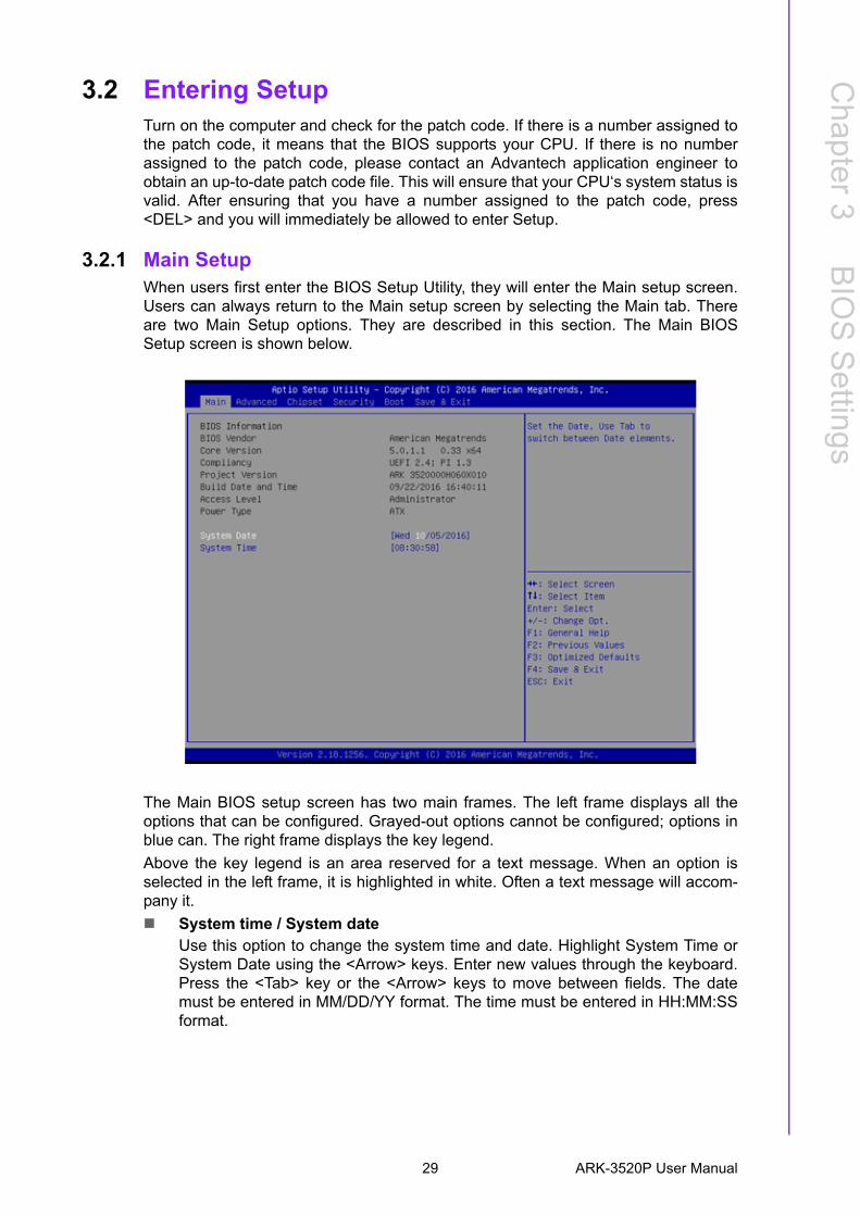
3.2.1 Main Setup When users first enter the BIOS Setup Utility, they will enter the Main setup screen.Users can always return to the Main setup screen by selecting the Main tab. Thereare two Main Setup options. They are described in this section. The Main BIOSSetup screen is shown below.
The Main BIOS setup screen has two main frames. The left frame displays all theoptions that can be configured. Grayed-out options cannot be configured; options inblue can. The right frame displays the key legend.
Above the key legend is an area reserved for a text message. When an option isselected in the left frame, it is highlighted in white. Often a text message will accom-pany it.
System time / System date Use this option to change the system time and date. Highlight System Time orSystem Date using the <Arrow> keys. Enter new values through the keyboard.Press the <Tab> key or the <Arrow> keys to move between fields. The datemust be entered in MM/DD/YY format. The time must be entered in HH:MM:SSformat.
29 ARK-3520P User Manual
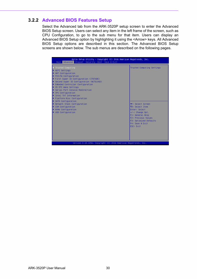
3.2.2 Advanced BIOS Features Setup Select the Advanced tab from the ARK-3520P setup screen to enter the AdvancedBIOS Setup screen. Users can select any item in the left frame of the screen, such asCPU Configuration, to go to the sub menu for that item. Users can display anAdvanced BIOS Setup option by highlighting it using the <Arrow> keys. All AdvancedBIOS Setup options are described in this section. The Advanced BIOS Setupscreens are shown below. The sub menus are described on the following pages.
ARK-3520P User Manual 30

Chapter 3
BIO
S S
ettings
3.2.2.1 ACPI Settings
Enable ACPI Auto ConfigurationEnable or disable BIOS ACPI auto configuration.
Enable HibernationEnables or Disables System ability to Hibernate (OS/S4 Sleep State). Thisoption may be not effective with some OS.
ACPI Sleep StateSelect the highest ACPI sleep state the system will enter when the SUSPENDbutton is pressed.
Lock Legacy ResourcesEnables or Disables Lock of Legacy Resources.
S3 Video RepostEnable or Disable S3 Video Repost.
31 ARK-3520P User Manual
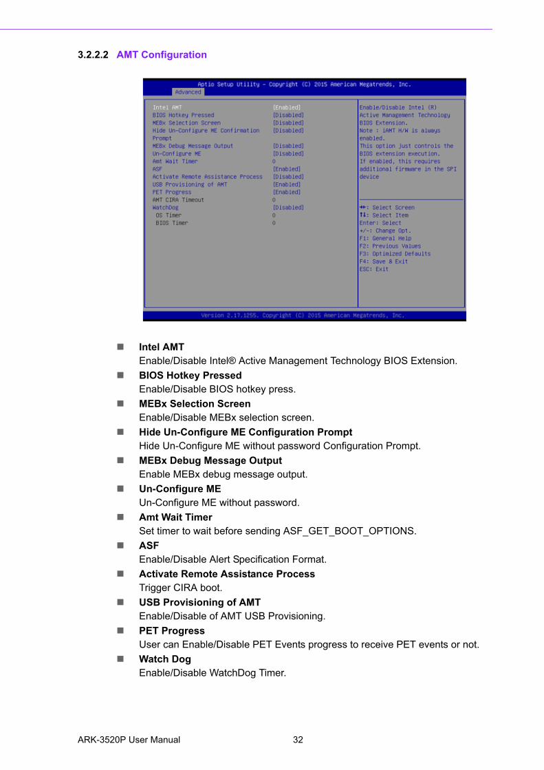
3.2.2.2 AMT Configuration
Intel AMTEnable/Disable Intel® Active Management Technology BIOS Extension.
BIOS Hotkey PressedEnable/Disable BIOS hotkey press.
MEBx Selection ScreenEnable/Disable MEBx selection screen.
Hide Un-Configure ME Configuration PromptHide Un-Configure ME without password Configuration Prompt.
MEBx Debug Message OutputEnable MEBx debug message output.
Un-Configure MEUn-Configure ME without password.
Amt Wait TimerSet timer to wait before sending ASF_GET_BOOT_OPTIONS.
ASFEnable/Disable Alert Specification Format.
Activate Remote Assistance ProcessTrigger CIRA boot.
USB Provisioning of AMTEnable/Disable of AMT USB Provisioning.
PET ProgressUser can Enable/Disable PET Events progress to receive PET events or not.
Watch DogEnable/Disable WatchDog Timer.
ARK-3520P User Manual 32

Chapter 3
BIO
S S
ettings
3.2.2.3 PCH-FW Configuration
PCH-FW ConfigurationThis page display all information about system ME FW.
ME StateSet ME to Soft Temporary Disabled.
TPM Device SelectionSelects TPM device.
33 ARK-3520P User Manual

3.2.2.4 Embedded Controller Configuration
EC Hardware MonitorThis page display all information about system Temperature/Voltage/Current.
Power Saving ModeThis item allows users to set board’s power saving mode when off.
Deep Sleep delay timeSet delay time for Deep Sleep mode.
Watch Dog TimerThis item allows users to select EC watchdog timer.
ARK-3520P User Manual 34

Chapter 3
BIO
S S
ettings
3.2.2.5 Trusted Computing
Trusted ComputingEnables or Disables BIOS support for security device. O.S. will not show Secu-rity Device. TCG EFI protocol and INT1A interface will not be available.
35 ARK-3520P User Manual

3.2.2.6 S5 RTC Wake Settings
Wake system from S5Enable or disable System wake on alarm event. Select FixedTime, system will
wake on the hr::min::sec specified.
ARK-3520P User Manual 36
Chapter 3
BIO
S S
ettings
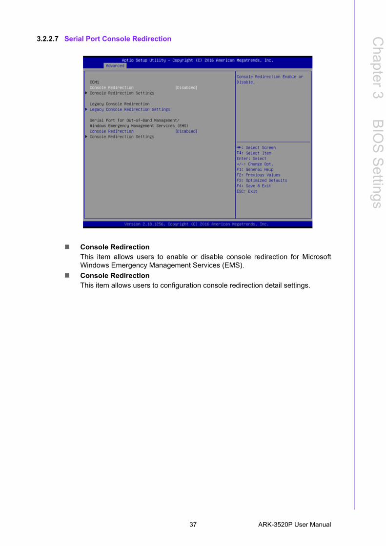
3.2.2.7 Serial Port Console Redirection
Console RedirectionThis item allows users to enable or disable console redirection for MicrosoftWindows Emergency Management Services (EMS).
Console RedirectionThis item allows users to configuration console redirection detail settings.
37 ARK-3520P User Manual

3.2.2.8 CPU Configuration
ARK-3520P User Manual 38

Chapter 3
BIO
S S
ettings
Hyper Threading TechnologyThis item allows users to enable or disable Intel? Hyper Threading technology.
Active Processor CoresThis item allows users to set how many processor cores should be active.
Intel Virtualization TechnologyThis item allows users to enable or disable the intel virtualization technology.
Hardware PrefetcherThis item allows users to enable or disable the hardware prefetcher feature.
Adjacent Cache Line PrefetchThis item allows users to enable or disable the adjacent cache line prefetch fea-ture.
CPU AESEnable/Disable CPU Advanced Encryption Standard instructions.
Intel® Speed Shift TechnologyEnable/Disable Intel® Speed Shift Technology support.
Intel® SpeedStep™Allows more than two frequency ranges to be supported.
CPU C statesEnable or disable CPU C states.
CState Pre-WakeDisable – to disable the CState Pre-Wake.
Package C State limitPackage C State limit.
3.2.2.9 Intel TXT Information
Intel TXT InformationDisplay Intel TXT information.
39 ARK-3520P User Manual
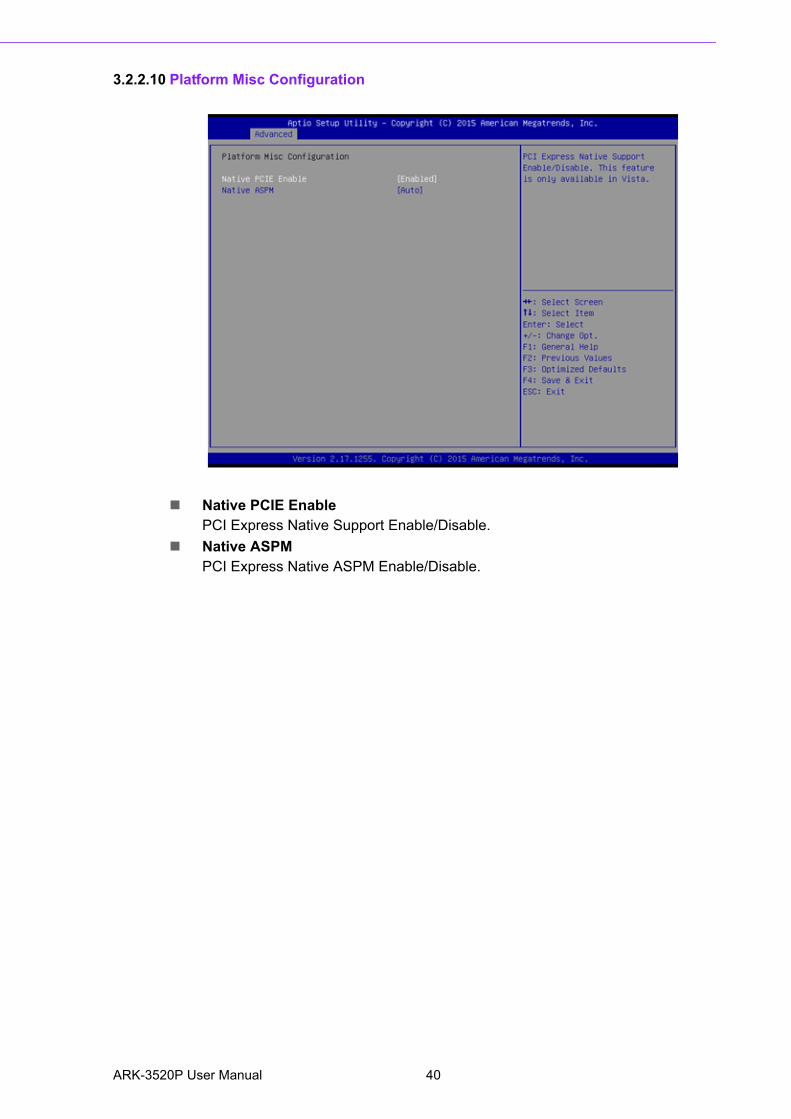
3.2.2.10 Platform Misc Configuration
Native PCIE EnablePCI Express Native Support Enable/Disable.
Native ASPMPCI Express Native ASPM Enable/Disable.
ARK-3520P User Manual 40

Chapter 3
BIO
S S
ettings
3.2.2.11 SATA Configuration
SATA ControllerEnable / Disable SATA Device.
SATA Mode SelectionDetermine how SATA controller operate.
Port 0 / Port 1 / mSATAEnable / Disable Serial ATA Port 1 / Port 2 / mSATA Port.
41 ARK-3520P User Manual

3.2.2.12 Network Stack Configuration
Network StackEnable/Disable UEFI Network Stack.
ARK-3520P User Manual 42

Chapter 3
BIO
S S
ettings
3.2.2.13 CSM Configuration
CSM SupportEnable/Disable CSM Support.
GateA20 ActiveUPON REQUEST - GA20 can be disabled using BIOS services. ALWAYS - donot allow disabling GA20; this option is useful when any RT code is executedabove 1MB.
Option ROM MessageBIOS Set display mode for Option ROM.
INT19 Trap ResponseBIOS reaction on INT19 trapping by Option ROM: IMMEDIATE - execute thetrap right away; POSTPONED - execute the trap during legacy boot.
Boot option filterThis option controls Legacy/UEFI ROMs priority.
NetworkControls the execution of UEFI and Legacy PXE OpROM.
StorageControls the execution of UEFI and Legacy Storage OpROM.
VideoControls the execution of UEFI and Legacy Video OpROM.
Other PCI devicesDetermines OpROM execution policy for devices other than Network, Storage,or Video.
43 ARK-3520P User Manual

3.2.2.14 USB Configuration
Legacy USB SupportEnables Legacy USB support. AUTO option disables legacy support if no USBdevices are connected. DISABLE option will keep USB devices available onlyfor EFI applications.
XHCI Hand-offThis is a workaround for OSes without XHCI hand-off support. The XHCI owner-ship change should be claimed by XHCI driver.
USB Mass Storage Driver SupportEnable/Disable USB Mass Storage Driver Support.
Port 60/64 EmulationEnables I/O port 60h/64h emulation support. This should be enabled for thecomplete USB keyboard legacy support for non-USB aware OSes.
USB transfer time-outTime-out value for control, Bulk, and interrupt transfers.
Device reset time-outUSB mass storage device start unit command time-out.
Device power-up delayMaximum time the device will take before it properly reports itself to the HostController. 'Auto' uses default value: for a Root port it is 100 ms, for a Hub portthe delay is taken from Hub descriptor.
ARK-3520P User Manual 44

Chapter 3
BIO
S S
ettings
3.2.2.15 First Super IO Configuration (IT8768E)
Serial Port 1 ConfigurationSet Parameters of Serial Port 1 (COMA).
Serial Port 2 ConfigurationSet Parameters of Serial Port 2 (COMB).
Serial Port 3 ConfigurationSet Parameters of Serial Port 3 (COMC).
Serial Port 4 ConfigurationSet Parameters of Serial Port 4 (COMD).
45 ARK-3520P User Manual

3.2.2.16 Second Super IO Configuration (NCT6106D)
Serial Port 5 ConfigurationSet Parameters of Serial Port 5 (COMA2).
Serial Port 6 ConfigurationSet Parameters of Serial Port 6 (COMB2).
Serial Port 7 ConfigurationSet Parameters of Serial Port 7 (COMC2).
Serial Port 8 ConfigurationSet Parameters of Serial Port 8 (COMD2).
Parallel Port ConfigurationSet Parameters of Parallel Port (LPT/LPTE).
ARK-3520P User Manual 46
Chapter 3
BIO
S S
ettings
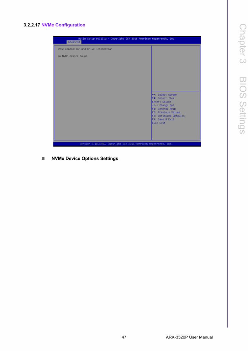
3.2.2.17 NVMe Configuration
NVMe Device Options Settings
47 ARK-3520P User Manual
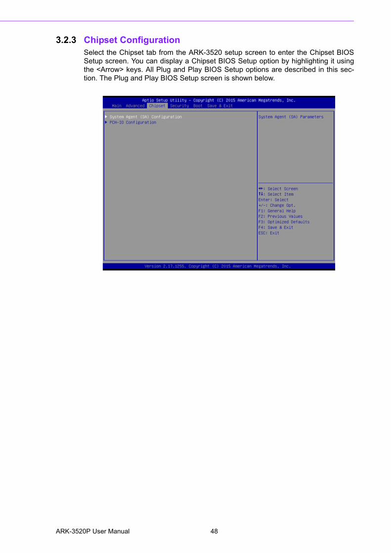
3.2.3 Chipset ConfigurationSelect the Chipset tab from the ARK-3520 setup screen to enter the Chipset BIOSSetup screen. You can display a Chipset BIOS Setup option by highlighting it usingthe <Arrow> keys. All Plug and Play BIOS Setup options are described in this sec-tion. The Plug and Play BIOS Setup screen is shown below.
ARK-3520P User Manual 48

Chapter 3
BIO
S S
ettings
3.2.3.1 System Agent (SA) Configuration
Above 4GB MMIO BIOS assigmentEnable/Disable above 4GB Memory Mapped IO BIOS assignment.
49 ARK-3520P User Manual
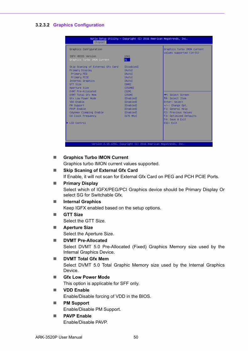
3.2.3.2 Graphics Configuration
Graphics Turbo IMON CurrentGraphics turbo IMON current values supported.
Skip Scaning of External Gfx CardIf Enable, it will not scan for External Gfx Card on PEG and PCH PCIE Ports.
Primary DisplaySelect which of IGFX/PEG/PCI Graphics device should be Primary Display Orselect SG for Switchable Gfx.
Internal GraphicsKeep IGFX enabled based on the setup options.
GTT SizeSelect the GTT Size.
Aperture SizeSelect the Aperture Size.
DVMT Pre-AllocatedSelect DVMT 5.0 Pre-Allocated (Fixed) Graphics Memory size used by theInternal Graphics Device.
DVMT Total Gfx MemSelect DVMT 5.0 Total Graphic Memory size used by the Internal GraphicsDevice.
Gfx Low Power ModeThis option is applicable for SFF only.
VDD EnableEnable/Disable forcing of VDD in the BIOS.
PM SupportEnable/Disable PM Support.
PAVP EnableEnable/Disable PAVP.
ARK-3520P User Manual 50

Chapter 3
BIO
S S
ettings
Cdynmax Clamping EnableEnable/Disable Cdynmax Clamping.
Cd Clock FrequencySelect the highest Cd Clock frequency supported by the platform.
3.2.3.3 LCD Control
Primary IGFX Boot DisplaySelect the Video Device which will be activated during POST. This has no effectif an external graphics present. Secondary boot display selection will appearbased on your selection. VGA modes will be supported only on primary display.
51 ARK-3520P User Manual

3.2.3.4 Memory Configuration Options
Max TOLUDMaximum Value of TOLUD.
3.2.3.5 GT – Power Management Control
RC6 Render Standby)Check to enable render standby support.
ARK-3520P User Manual 52

Chapter 3
BIO
S S
ettings
3.2.3.6 PEG Port Configuration
PEG Link and Speed Information Enable Root Port
Enable or Disable the Root Port.
Max Link SpeedConfigure PEG Max Speed.
Max Link WidthForce PEG link to retrain to X1/2/4/8 or Auto.
ASPMEnable PCI Express Active State Power Management settings.
Detect Non-Compliance DeviceDetect Non-Compliance PCI Express Device in PEG.
53 ARK-3520P User Manual

3.2.3.7 PCH-IO Configuration
PCI Express ConfigurationPCI Express Configuration Settings.
USB ConfigurationUSB Configuration Settings.
HD Audio ConfigurationHD Audio Susbsystem Configuration Settings.
SB Porting ConfigurationSB Porting Configuration Settings.
PCH LAN ControllerEnable or Disable onboard NIC.
LAN Option ROMEnable or Disable onboard LAN’s PXE option ROM.
Wake on LANEnable or Disable Integrated LAN to wake the system from S5.
Onboard LAN2 ControllerEnable or Disable onboard NIC.
LAN Option ROMEnable or Disable onboard LAN’s PXE option ROM.
PCIE WakeEnable or Disable PCIE to wake the system from S5.
High Precision TimerEnable or Disable High Precision Event Timer.
State After S3Specify what state to go to when power is re-applied after a power failure (G3state).
ARK-3520P User Manual 54

Chapter 3
BIO
S S
ettings
3.2.3.8 PCI Express Configuration
PCI Express Clock GatingEnable or disable PCI Express Clock Gating for each root port.
DMI Link ASPM ControlEnable/Disable the control of Active State Power Management on SA side of theDMI Link.
PCI Express Root Port 1/2/3/4/7/8/9PCI Express Port 1/2/3/4/7/8/9 Settings.
55 ARK-3520P User Manual

3.2.3.9 USB Configuration
USB PreconditionPrecondition work on USB host controller and root ports for faster enumeration.
XHCI Disable Compliance modeOption to disable Compliance Mode.
3.2.3.10 HD Audio Configuration
HD AudioControl Detection of the HD-Audio device. Disabled = HDA will be uncondition-ally disabled. Enabled = HDA will be unconditionally Enabled.
ARK-3520P User Manual 56

Chapter 3
BIO
S S
ettings
3.2.3.11 SB Porting Configuration
SATA RAID ROMRun the Legacy ROM or UEFI Driver.
57 ARK-3520P User Manual

3.2.4 Security
Select Security Setup from the PCM-3365 Setup main BIOS setup menu. All SecuritySetup options, such as password protection and virus protection are described in thissection. To access the sub menu for the following items, select the item and press<Enter>:
Change Administrator / User PasswordSelect this option and press <ENTER> to access the sub menu, and then typein the password.
ARK-3520P User Manual 58

Chapter 3
BIO
S S
ettings
3.2.5 Boot
Setup Prompt TimeoutNumber of seconds that the firmware will wait before initiating the originaldefault boot selection. A value of 0 indicates that the default boot selection is tobe initiated immediately on boot. A value of 65535(0xFFFF) indicates that firm-ware will wait for user input before booting. This means the default boot selec-tion is not automatically started by the firmware.
Bootup NumLock StateSelect the keyboard NumLock state.
Quiet BootEnables or disables Quiet Boot option.
Boot Option #1Sets the system boot order.
Fast BootEnables or disables boot with initialization of a minimal set of devices requiredto launch active boot option. Has no effect for BBS boot options.
New Boot Option PolicyControls the placement of newly detected UEFI boot options.
59 ARK-3520P User Manual

3.2.6 Save & Exit
Save Changes and ExitThis item allows you to exit system setup after saving the changes.
Discard Changes and ExitThis item allows you to exit system setup without saving any changes.
Save Changes and ResetThis item allows you to reset the system after saving the changes.
Discard Changes and ResetThis item allows you to rest system setup without saving any changes.
Save ChangesThis item allows you to save changes done so far to any of the options.
Discard ChangesThis item allows you to discard changes done so far to any of the options.
Restore DefaultsThis item allows you to restore/load default values for all the options.
Save as User DefaultsThis item allows you to save the changes done so far as user defaults.
Restore User DefaultsThis item allows you to restore the user defaults to all the options.
Boot OverrideBoot device select can override your boot priority.
ARK-3520P User Manual 60

Appendix A
A Watchdog Timer Sample Code
A.1 EC Watchdog Timer Sample CodeEC_Command_Port = 0x29AhEC_Data_Port = 0x299hWrite EC HW ram = 0x89Watch dog event flag = 0x57Watchdog reset delay time = 0x5EReset event = 0x04 Start WDT function = 0x28 ====================================================.model small.486p.stack 256.data.codeorg 100h.STARTup
mov dx, EC_Command_Portmov al,89h ; Write EC HW ram.out dx,al
mov dx, EC_Data_Portmov al, 5Fh ; Watchdog reset delay time low byte (5Eh is high byte) index, Timebase:100msout dx,al
mov dx, EC_Data_Portmov al, 64h ;Set 10 seconds delay time.out dx,al
mov dx, EC_Command_Portmov al,89h ; Write EC HW ram.out dx,al
mov dx, EC_Data_Portmov al, 57h ; Watch dog event flag.out dx,al
mov dx, EC_Data_Portmov al, 04h ; Reset event.out dx,al
mov dx, EC_Command_Portmov al,28h ; start WDT function. (Stop: 0x29, Reset: 0x2A)out dx,al
.exit
ARK-3520P User Manual 62

Appendix A
Watchdog
Tim
erS
ample
Code
END
63 ARK-3520P User Manual

ARK-3520P User Manual 64
Appendix B
B USB 3.0 Drivers Installation Instruction
B.1 USB 3.0 Drivers Installation Instruction For customers using Windows 7 OS, they need to install drivers to active the USB 3.0function. Please download driver installation instructions from the Intel website. (https://downloadcenter.intel.com/download/25476/Windows-7-USB-3-0-Creator-Utility)
ARK-3520P User Manual 66

Appendix B
US
B 3.0
Drivers
InstallationInstruction
67 ARK-3520P User Manual

www.advantech.comPlease verify specifications before quoting. This guide is intended for referencepurposes only.All product specifications are subject to change without notice.No part of this publication may be reproduced in any form or by any means,electronic, photocopying, recording or otherwise, without prior written permis-sion of the publisher.All brand and product names are trademarks or registered trademarks of theirrespective companies.© Advantech Co., Ltd. 2017