user instruction manual rollgliss r500 rescue &...
TRANSCRIPT

WARNING: This product is part of an emergency rescue system. The user must follow manufacturer’s instructions for each part of the system. These instructions must be provided to the user of this equipment. The user must read and understand these instructions before using this equipment. Manufacturer’s instructions must be followed for proper use and maintenance of this equipment. Alterations or misuse of this equipment, or failure to follow instructions, may result in serious injury or death.
IMPORTANT: If you have questions on the use, care, or suitability of this equipment for your application, contact Capital Safety.
IMPORTANT: Record the product identification information from the ID label in the inspection and maintenance log in Section 9 of this manual.
descRIPTION:
The R500 Rescue & Escape Device (Figure 1) is available in Descent with Rescue Lifting or Descent Only models. Descent with Rescue Lifting models are available with an integral bracket for attachment to fixed ladders. A Humidity Resistant Case to protect the R500 Descender against environmental conditions is available on some models.
Figure 1 - R500 Rescue & Escape Devices
Rollgliss R500
Models: 3322XXX
Rollgliss R500 with Rescue Lifting
Models: 3321XXX & 3323XXX
Rollgliss R500 with Rescue Lifting & Ladder Bracket
Models: 3320XXX & 3324XXX
Humidity Resistant Case (Included with
Models 3323XXX & 3324XXX)
XXX The last three digits of the Model Number (signified by ‘XXX’) indicate the maximum descent length in feet. Available descent lengths range from 50 ft. (15 m) to 1,000 ft. (305 m) in 25 ft. (8 m) increments.
© Copyright 2011, DB Industries, Inc.
Rollgliss®
R500 Rescue & Escape Device
Model Numbers: (See back pages.)
UseR INsTRUcTION MANUAl ROllGlIss® R500 RescUe & escAPe devIce
This manual is intended to meet the Manufacturer’s Instructions as required by ANSI Z359.4 and CSA Z259.2.3. It should be used as part of an employee training program as required by OSHA.
Form: 5902448 Rev: E

2
1.0 ApplicATioN
1.1 PuRPosE: The R500 Rescue & Escape Device is intended to lower one or two people simultaneously from an elevated height to a lower level in a rescue situation. Multiple people may descend one after another using the device. The descent speed is automatically limited during descent. Models incorporating a hand wheel allow for raising persons a short distance to facilitate rescue.
WARNING: The R500 Rescue & Escape Device must not be used as a fall arrest device.
1.2 LIMITATIoNs: The following application limitations must be recognized and considered before using this product:
A. CAPACITY: Required capacities and descent distances for the Rollgliss R500 are as follows:
users Total Weight (including tools, clothing, etc.) Max. Descent Distance Number of Descents
2 Persons 130 lbs (59 kg) - 620 lbs (282 kg) 541 ft. (165 m) 2
1 Person 130 lbs (59 kg) - 310 lbs (141 kg) 1,083 ft. (330 m) 16
1 Person 130 lbs (59 kg) - 220 lbs (100 kg) 1,083 ft. (330 m) 22
1 Person 130 lbs (59 kg) - 165 lbs (75 kg) 1,083 ft. (330 m) 30
B. DEsCENT sPEED: The speed at which the user(s) will be lowered when using the Rollgliss R500 Rescue & Escape Device increases with the combined weight of the user(s). The approximate descent speed is 2-3 ft/s (0.6 - 0.9 m/s).
C. HAZARDous AREAs: Use of this equipment in hazardous areas may require additional precautions to reduce the possibility of injury to the user or damage to the equipment. Hazards may include, but are not limited to: high heat, caustic chemicals, corrosive environments, high voltage power lines, explosive or toxic gases, moving machinery, and sharp edges.
D. TRAINING: This equipment is intended to be installed and used by persons trained in its correct application and use.
1.3 APPLICABLE sTANDARDs: Refer to ANSI standard Z359.4, CSA Z259.2.3 and other applicable local, state, and federal (OSHA) standards for requirements governing the use of this equipment.
2.0 SySTeM RequiReMeNTS
2.1 CoMPATIBILITY oF CoMPoNENTs: DBI-SALA equipment is designed for use with DBI-SALA approved components and subsystems only. Substitutions or replacements made with non-approved components or subsystems may jeopardize compatibility of equipment and may effect the safety and reliability of the complete system.
2.2 CoMPATIBILITY oF CoNNECToRs: Connectors (hooks, carabiners, D-rings) used to suspend the R500 Rescue & Escape Devices must be capable of supporting at least 3,100 lbs (1,406 kg). Connectors must be compatible in size, shape, and strength. Non compatible connectors may unintentionally disengage (roll-out). Roll-out occurs when interference between the connector and anchorage connector causes the hook or carabiner gate to unintentionally open and release. Self locking snap hooks and carabiners must be used with this system to reduce the possibility of roll-out. Do not use connectors that will not completely close over the attachment element.
2.3 ANCHoRAGE sTRENGTH - R500 REsCuE & EsCAPE DEvICE: Anchorages used to suspend the R500 Rescue & Escape Device must sustain static loads, applied along the axis of the device, of at least 3,100 lbs (1,406 kg). When more than one R500 Descender is attached to an anchorage the strengths stated above must be multiplied by the number of descent devices attached to the anchorage.
3.0 iNSTAllATioN ANd uSe
3.1 BEFoRE EACH usE: Carefully inspect the R500 Rescue & Escape Device in accordance with Section 5 of this manual.
3.2 PLANNING: Plan your emergency escape system and how it will be used before starting your work. Consider all factors that will affect your safety before, during, and after an escape. Consider the following when planning your system:
A. ANCHoRAGE: Select a rigid anchorage point that is capable of supporting at least 3,100 lbs (1,406 kg). (See Section 2.3).

3
B. DEsCENT PATH AND LANDING AREA CLEARANCE: The planned descent path must be unobstructed. The landing area must be clear of obstructions to permit safe landing of the user. Failure to provide an unobstructed descent path and landing area may result in serious injury. Maintain a minimum distance of 1 foot (31 cm) from any vertical surface to ensure safe descent. The R500 Rescue & Escape Device ships with a separate Pulley that can be used to re-direct the lifeline away from obstructions.
C. TEsTING THE sYsTEM: DBI-SALA recommends performing a test descent using a 120 lb (55 kg) weight. The descent speed should be uniform, and allow the user to reach the landing area safely. Record all descents in the Descent Log (Section 10).
D. sHARP EDGEs: Avoid using this equipment where system components will be in contact with, or abrade against, unprotected sharp edges. An Edge Protector (Figure 2) or protective padding must be used when descending over sharp edges.
3.3 INsTALLATIoN: The R500 Rescue & Escape Device is available in several configurations and therefore its installation will vary.
• Connecting the R500 Descender to Anchorage: Figure 3 illustrates attachment of the Emergency Descent Device to an anchorage. See Section 2 for compatibility and anchorage strength requirements.
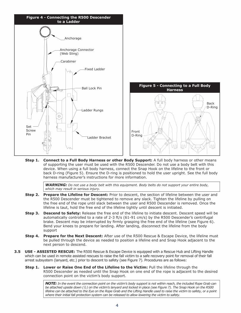
• Connecting the R500 Descender to a Fixed Ladder: Models equipped with a ladder bracket are intended to be attached to the rungs of a fixed ladder (see Figure 4). The R500 Descender mounts on the Ladder Bracket with a Set Screw Pin in the ladder bracket aligning hole and a Ball Lock Pin inserted through mounting holes in the R500 and ladder bracket. R500 Descenders mounted with the ladder bracket still require that the unit be secured by the anchorage handle to an anchorage of sufficient strength (see Section 2.3).
• Preparing the Lifeline: Lower one end of the lifeline to the ground or landing below. Ensure the lifeline is free of knots or kinks.
3.4 usE - sINGLE PERsoN uNAssIsTED EsCAPE: Procedures for performing and unassisted descent with the R500 Rescue & Escape Device are as follows:
WARNING: The users of this equipment must be in good physical condition. The user must have the ability to absorb the landing.
Figure 2 - Edge Protector Figure 3 - Connecting the R500 Descender to Anchorage
Anchorage Connector
Anchorage Connector
Anchorage
Carabiner
Carabiner
Web Lanyard
Anchorage
Anchorage
Anchorage Connector (Web Sling)
4
Figure 4 - Connecting the R500 Descender to a Ladder
Anchorage
Anchorage Connector(Web Sling)
Carabiner
Fixed Ladder
Ladder Rungs
Ladder Bracket
Ball Lock Pin
SetScrewPin
Figure 5 - Connecting to a Full Body Harness
Front D-Ring
Back D-Ring
step 1. Connect to a Full Body Harness or other Body support: A full body harness or other means of supporting the user must be used with the R500 Descender. Do not use a body belt with this device. When using a full body harness, connect the Snap Hook on the lifeline to the front or back D-ring (Figure 5). Ensure the D-ring is positioned to hold the user upright. See the full body harness manufacturer’s instructions for more information.
WARNING: Do not use a body belt with this equipment. Body belts do not support your entire body, which may result in serious injury.
step 2. Prepare the Lifeline for Descent: Prior to descent, the section of lifeline between the user and the R500 Descender must be tightened to remove any slack. Tighten the lifeline by pulling on the free end of the rope until slack between the user and R500 Descender is removed. Once the lifeline is taut, hold the free end of the lifeline tightly until descent is initiated.
step 3. Descend to safety: Release the free end of the lifeline to initiate descent. Descent speed will be automatically controlled to a rate of 2-3 ft/s (61-91 cm/s) by the R500 Descender’s centrifugal brake. Descent may be interrupted by firmly grasping the free end of the lifeline (see Figure 6). Bend your knees to prepare for landing. After landing, disconnect the lifeline from the body support
step 4. Prepare for the Next Descent: After use of the R500 Rescue & Escape Device, the lifeline must be pulled through the device as needed to position a lifeline end and Snap Hook adjacent to the next person to descend.
3.5 usE - AssIsTED REsCuE: The R500 Rescue & Escape Device is equipped with a Rescue Hub and Lifting Handle which can be used in remote assisted rescues to raise the fall victim to a safe recovery point for removal of their fall arrest subsystem (lanyard, etc.) prior to descent to safety (see Figure 7). Procedures are as follows:
step 1. Lower or Raise one End of the Lifeline to the victim: Pull the lifeline through the R500 Descender as needed until the Snap Hook on one end of the rope is adjacent to the desired connection point on the victim’s body support.
NOTe: In the event the connection point on the victim’s body support is not within reach, the included Rope Grab can be attached upside down (ò) on the victim’s lanyard and locked in place (see Figure 7). The Snap Hook on the R500 lifeline can be attached to the Eye on the Rope Grab and the Lifting Handle used to raise the victim to safety, or a point where their initial fall protection system can be released to allow lowering the victim to safety.

5
Figure 6 - Descent Control
For additional descent control:
To suspend descentand hold the victim during rescue:
Pigtail
Cam Cleats
To slow or interrupt descent:
FreeEnd
FreeEnd
FreeEnd
Pigtail
NOTe: Descent may be interrupted by firmly grasping the free end of the rope. For additional leverage, the free end of the rope can be passed through the Pigtail and then grasped. To suspend descent for longer durations and free both hands for rescue, the free end of the rope should be passed through the Rope Guide and then secured in the Cam Cleats.
Figure 7 - Rescue Applications
Victim’sLanyard
RopeGrab
R500Lifeline
Eye
RollglissR500
RollglissR500
Rescue End Snap Hook
Rescue End Snap Hook
Harness D-Ring
Harness D-Ring
Harness D-Ring
Rescue Lanyard
Rescue Hub & Lifting Handle
Remote Assisted Rescue
simultaneousRescue/Escape
RescueHub
LiftingHandle
step 2. Connect to the victim’s Full Body Harness or other Body support: Connect the Snap Hook on the Rescue End of the lifeline to the front or back D-ring (Figure 5). Ensure the D-ring is positioned to hold the user upright.
WARNING: Do not use a body belt with this equipment. Body belts do not support the entire body, which may result in serious injury.
step 3. Raise the victim to a safe Recovery Point and Disconnect the Fall Arrest subsystem: Fold the Lifting Handle out of the Rescue Hub. Grasp the Lifting Handle and Rotate the Rescue Hub clockwise to raise the victim to a Safe Recovery Point. Once the victim is at a safe location, secure the Free End of the lifeline with the R500 Descender’s Pigtail and Cam Cleats to prevent unintentional descent (see Figure 6). Disconnect the Victim’s fall arrest subsystem (Lanyard, etc.).
step 4. Prepare the Lifeline for Descent: Prior to descent, the section of lifeline between the user and the R500 Descender must be tightened to remove any slack. Tighten the lifeline by pulling on the free end of the lifeline until slack between the user and R500 Descender is removed. Once the lifeline is taut, hold the free end of the lifeline tightly until descent is initiated.

6
step 5. Descend to safety: Release the free end of the lifeline to initiate descent. Descent speed will be automatically controlled to a rate of 2-3 ft/s (61-91 cm/s) by the R500 Descender’s centrifugal brake. Descent may be interrupted by firmly grasping the free end of the lifeline (see Figure 6). Bend your knees to prepare for landing. After landing, disconnect the lifeline from the body support. Record all descents in the Descent Log (Section 10).
3.6 usE - sIMuLTANEous REsCuE/EsCAPE: In situations where the fall victim requires assistance, simultaneous rescue/escape allows a rescuer1 to accompany the victim during descent (see Figure 7):
WARNING: Two person descents with the R500 Rescue & Escape Device should not exceed a total combined weight (including tools, clothing, body support, etc.) of 620 lbs (282 kg) and a descent distance of 541 ft. (165 m).
step 1. Descend to the victim: In situations where the fall victim is suspended by their existing Fall Arrest subsystem, it will be necessary for the rescuer to descend to the victim’s location to provide assistance. Descend to the victim per the steps in Section 3.4.
IMPORTANT: When the victims position is reached, descent can be interrupted by firmly grasping and holding the free end of the rope. If a secondary rescuer is available at the R500 Descender, the free end of the rope can be passed through the Rope Guide and then secured in the Cam Cleats to prevent unintentional descent while the primary rescuer is securing the victim.
step 2. Connect the victim to the R500 Rescue & Escape Device: Connect a Rescue Lanyard (or similar equipment) between the Lifeline Snap Hook connected to the Rescuer’s Full Body Harness Front D-Ring and the Back D-Ring on the Victim’s Full Body Harness (Figure 7).
step 3. Disconnect the victim’s Fall Arrest subsystem: Ensure that the victim is securely attached to the R500 Rescue & Escape Device and then cut or detach the victim’s fall arrest subsystem (lanyard, etc.) to free the victim for descent.
NOTe: If a secondary rescuer is available at the R500 Descender, the Rescue Hub and Lifting Wheel can be used to raise the victim slightly for detachment of their fall arrest subsystem.
step 4. Descend to safety: Release the free end of the lifeline to initiate descent. Descent speed will be automatically controlled to a rate of 2-4 ft/s (0.6-1.2 m/s) by the R500 Descender’s centrifugal brake. Descent may be interrupted by firmly grasping the free end of the lifeline (see Figure 6). Bend your knees to prepare for landing. After landing, disconnect the lifeline from the body support. Record all descents in the Descent Log (Section 10).
4.0 TRAiNiNg
It is the responsibility of the user and purchaser of this equipment to be trained in the correct care and use of this equipment. The user and purchaser must be aware of the operating characteristics, application limits, and consequences of improper use of this equipment.
WARNING: Training must be conducted without exposing the trainee to a fall hazard. Training should be repeated on a periodic basis.
5.0 iNSpecTioN
To ensure safe, efficient operation, the R500 Rescue & Escape Device should be inspected at intervals defined in Section 5.1. See Section 5.3 for inspection procedures.
5.1 FREquENCY: In addition to inspecting the R500 Rescue & Escape Device prior to each use, Inspection should be performed at the following regular intervals:
huMidiTy ReSiSTANT cASe iNSpecTioN: If the R500 Rescue & Escape Device is stored continuously in a Humidity Resistant Case (see Figure 9), Monthly and yearly inspections are not required. In addition to inspection prior to each use (see Section 5.3), the Humidity Indicator on the case (see Figure 9) should be inspected annually and the date and inspector’s initials logged on the Case Inspection Label (see Section 8). If the Humidity Indicator displays a orange or brown spot (Spot-Type Indicator) or reading of 60 or greater (Pie Sector Indicator), the case should be removed from service and the contents inspected per the Inspection Steps defined in Section 5.3.
1 Rescuer: Person or persons other than the rescue subject acting to perform an assisted rescue by operation of a rescue system.

7
• Monthly: A formal inspection should be completed by a competent person2 other than the user. A formal inspection should be completed if the system parameters are changed, such as after a system is moved, Re-rigged, anchorages moved, etc. Extreme working conditions may require increasing the Inspection frequency. Inspect the R500 Rescue & Escape Device in accordance with Section 5.3 and Section 5.4. Record inspection results in the Inspection and Maintenance Log, or use the i-Safe™ inspection web portal to maintain inspection records (see Section 5.2).
IMPORTANT: A monthly inspection is not required if the R500 Rescue & Escape Device is continuously stored in a Humidity Resistant Case (see Figure 9) and pre-use and annual inspections of the case’s Humidity Indicator validate allowable humidity levels.
• Every Two Years: The R500 Descender must be sent to an authorized service center for inspection and service (see Section 6.2).
IMPORTANT: A 2 Year inspection is not required if the R500 Rescue & Escape Device is continuously stored in a Humidity Resistant Case (see Figure 9) and pre-use and annual inspections of the case’s Humidity Indicator validate allowable humidity levels.
5.2 I-sAFE™ RFID TAG: R500 Rescue & Escape Devices are equipped with an i-Safe™ Radio Frequency Identification (RFID) tag (Figure 8). The i-Safe™ RFID tag on the R500 Descender can be used in conjunction with the i-Safe handheld reading device and the web based portal to simplify inspection and inventory control and provide records for fall protection equipment. If you are a first-time user, contact a Customer Service representative in the US at 800-328-6146 or in Canada at 800-387-7484. If you have already registered, go to: www.capitalsafety.com/isafe. Follow the instructions provided with the i-Safe handheld reader or on the web portal to transfer your data to the web log.
5.3 INsPECTIoN sTEPs: Per the intervals defined in Section 5.1, inspect the R500 Descender as follows:
step 1. If the R500 Rescue & Escape Device is stored in a Humidity Resistant Case, inspect the Humidity Indicator on the outside of the case (see Figure 9). If the Humidity Indicator displays a orange or brown spot (spot-type indicator), or reading of 60 or greater (pie sector indicator): (1) Open the case and inspect the R500 Descender per the remaining steps. (2) Maintain the case as described in Section 6.1.
step 2. Inspect device for loose fasteners and bent or damaged parts.
step 3. Inspect device housing for distortion, cracks, or other damage. Ensure the anchorage handle is not damaged or distorted.
step 4. The lifeline must pull through the device. Inspect the entire rope for cuts, burns, severely abraded areas, and excessive wear.
step 5. Device labels must be present and fully legible (see Section 8).
step 6. Inspect for corrosion on the device.
step 7. Inspect carabiners for damage, corrosion, and working condition.
step 8. Inspect all system components and subsystems according to manufacturer’s instructions.
step 9. Record inspection results in the Inspection and Maintenance Log (Section 9) or on the i-Safe web portal (Section 5.2).
5.4 uNsAFE oR DEFECTIvE CoNDITIoNs: If inspection reveals an unsafe or defective condition, remove the device from service and contact an authorized service center for repair.
Figure 8 - i-safe™ RFID Tag Figure 9 - Humidity Resistant Case (9504927)
Pie SectorIndicator Disk
Spot-Type Indicator Disk
HumidityIndicator
2 competent person: Person who is knowledgeable of the current periodic examination requirements, recommendations and inslructions issued by the manufacturer applicable to the relevant component, subsystem or system.

8
6.0 MAiNTeNANce, SeRvice, SToRAge
6.1 MAINTENANCE:
• Rollgliss R500 Descender: Periodically clean the exterior of the R500 Rescue & Escape Device with water and mild detergent. Position the device so excess water will drain out. Clean labels as required. Clean lifeline with water and mild detergent. Rinse and thoroughly air dry. Do not force dry with heat. A buildup of dirt, paint, etc., may prevent the lifeline from pulling through the device. Ensure no knots are present.
• Humidity Resistant Case: If inspection of the Humidity Indicator indicates the Humidity Resistant Case has experienced high humidity (see Section 5.3), perform the following maintenance:
◊ If the Humidity Indicator on the exterior of the Humidity Resistant Case has a Spot-Type Indicator Disc, it should be replaced with a Pie Sector Indicator Disc (see Figure 10):
A. Grasp the Humidity Indicator housing by the Hex Flange on the outside of the case.
B. Insert a 1/2” hex wrench (Allen Wrench) into the Externally Threaded Collar and turn the Collar counter-clockwise to loosen.
C. Remove the Externally Threaded Collar.
D. Remove the Teflon Washer.
E. Remove the Spot-Type Humidity Indicator Disc
F. Install the Pie Sector Indicator Disc (P/N 9505223).
G. Install the Teflon Washer.
H. Install the Externally Threaded Collar.
I. Hold the Humidity Indicator housing by the Hex Flange and Torque the Externally Threaded Collar to 45-55 inch-lbs (5-6 Nm ).
◊ Just prior to resealing the Humidity Resistant Case, replace all Moisture Absorber Packets in the case with new packets (P/N 9505148). Each new Moisture Absorber Packet is wrapped in a foil bag. Remove the foil bag before placing the the new packet in the case.
Figure 10 - Humidity Indicator Disc Replacement
ExternallyThreadedCollar
AllenWrench
HexFlange
HumidityIndicator
Disk
TeflonWasher
ExternallyThreaded
Collar
Pie SectorIndicator Disk
Spot-Type Indicator Disk
6.2 sERvICE: Maintenance and service must be completed by an authorized service center. An authorization and return number must be issued by Capital Safety. Do not attempt to disassemble the device. The R500 Descender requires service by an authorized service center every two years. Service by and authorized service center is also required when the Maximum Cumulative Descent Distance has been reached. Descent Distances should be logged and totaled in the Descent Log (Section 10). Service shall include an intensive inspection and cleaning of all components and replacement of Friction Pads as required. Failure to provide required service may shorten the product life and compromise safety and performance.
NOTe: Only Capital Safety or parties authorized in writing may make repairs to this equipment.
6.3 sToRAGE: Store the R500 Rescue & Escape Device in a cool, dry, clean environment, out of direct sunlight. Avoid areas where chemical or organic vapors are present. Thoroughly inspect the R500 Descender after extended storage.
9
7.0 SpecificATioNS
7.1 MATERIALs:
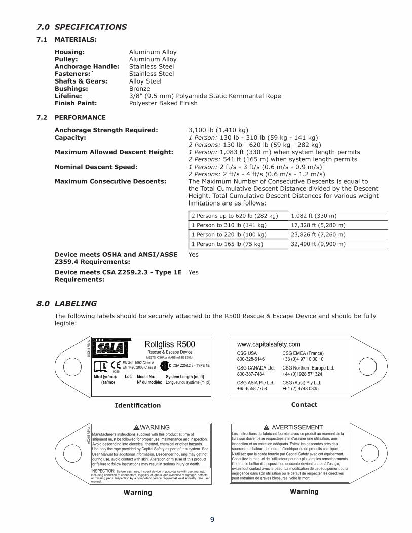
Housing: Aluminum AlloyPulley: Aluminum AlloyAnchorage Handle: Stainless SteelFasteners:` Stainless Steelshafts & Gears: Alloy SteelBushings: BronzeLifeline: 3/8” (9.5 mm) Polyamide Static Kernmantel RopeFinish Paint: Polyester Baked Finish
7.2 PERFoRMANCE
Anchorage strength Required: 3,100 lb (1,410 kg)Capacity: 1 Person: 130 lb - 310 lb (59 kg - 141 kg)
2 Persons: 130 lb - 620 lb (59 kg - 282 kg)Maximum Allowed Descent Height: 1 Person: 1,083 ft (330 m) when system length permits
2 Persons: 541 ft (165 m) when system length permitsNominal Descent speed: 1 Person: 2 ft/s - 3 ft/s (0.6 m/s - 0.9 m/s)
2 Persons: 2 ft/s - 4 ft/s (0.6 m/s - 1.2 m/s)Maximum Consecutive Descents: The Maximum Number of Consecutive Descents is equal to
the Total Cumulative Descent Distance divided by the Descent Height. Total Cumulative Descent Distances for various weight limitations are as follows:
2 Persons up to 620 lb (282 kg) 1,082 ft (330 m)
1 Person to 310 lb (141 kg) 17,328 ft (5,280 m)
1 Person to 220 lb (100 kg) 23,826 ft (7,260 m)
1 Person to 165 lb (75 kg) 32,490 ft.(9,900 m)
Device meets osHA and ANsI/AssE Z359.4 Requirements:
Yes
Device meets CsA Z259.2.3 - Type 1E Requirements:
Yes
8.0 lAbeliNg
The following labels should be securely attached to the R500 Rescue & Escape Device and should be fully legible:
Identification Contact
Warning Warning

10
Specifications Specifications
Specifications&Inspection Descent
use use
Inspection Log i-safe™
i-safe™ RFID
Case Inspection

11
9.0 iNSpecTioN ANd MAiNTeNANce log
sERIAL NuMBER:
MoDEL NuMBER:
DATE PuRCHAsED: DATE oF FIRsT usE:
INsPECTIoN DATE INsPECTIoN ITEMs NoTED
CoRRECTIvE ACTIoN MAINTENANCE PERFoRMED
Approved By:
Approved By:
Approved By:
Approved By:
Approved By:
Approved By:
Approved By:
Approved By:
Approved By:
Approved By:
Approved By:
Approved By:
Approved By:
Approved By:
Approved By:
Approved By:
Approved By:
Approved By:
Approved By:
12
INsPECTIoN DATE INsPECTIoN ITEMs NoTED
CoRRECTIvE ACTIoN MAINTENANCE PERFoRMED
Approved By:
Approved By:
Approved By:
Approved By:
Approved By:
Approved By:
Approved By:
Approved By:
Approved By:
Approved By:
Approved By:
Approved By:
Approved By:
Approved By:
Approved By:
Approved By:
Approved By:
Approved By:
Approved By:
Approved By:
Approved By:
Approved By:
Approved By:

13
10.0 deSceNT log
sERIAL NuMBER:
MoDEL NuMBER:
DATE PuRCHAsED: DATE oF FIRsT usE:
DATE DEsCENT WEIGHT DEsCENT DIsTANCE CuMuLATIvE DEsCENT DIsTANCE Total of Descent Distances at left since last Service Date (below).
1. Match the greatest descent Weight logged above with the appropriate Weight limit in the table below to determine the allowed Maximum cumulative descent distance.
Weight Limits Max. Cumulative Descent Distance
2 Persons up to 620 lb (282 kg) 1,082 ft (330 m)
1 Person to 310 lb (141 kg) 17,328 ft (5,280 m)
1 Person to 220 lb (100 kg) 23,826 ft (7,260 m)
1 Person to 165 lb (75 kg) 32,490 ft.(9,900 m)
2. if the cumulative descent distance calculated above meets or exceeds the Maximum cumulative descent distance from Step 1, the R500 Rescue & escape device should be serviced by an Authorized Service center. Service dates should be logged below:
service Date service Date
14
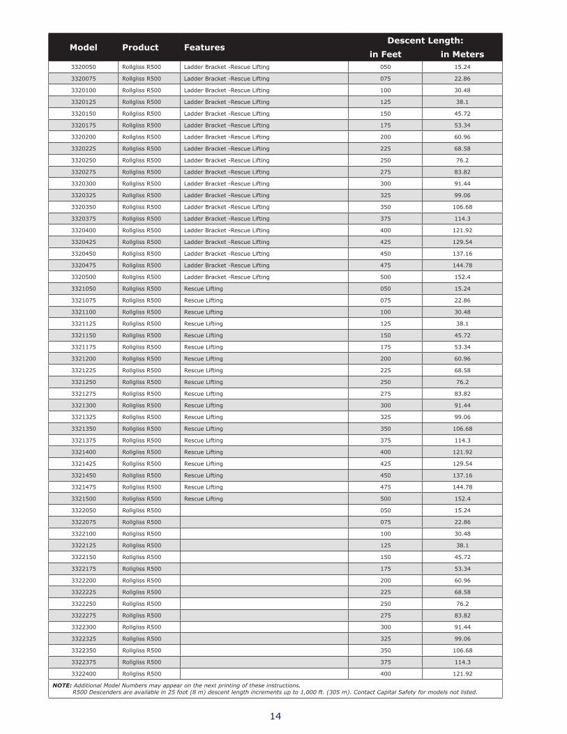
Model Product FeaturesDescent Length:
in Feet in Meters3320050 Rollgliss R500 Ladder Bracket -Rescue Lifting 050 15.24
3320075 Rollgliss R500 Ladder Bracket -Rescue Lifting 075 22.86
3320100 Rollgliss R500 Ladder Bracket -Rescue Lifting 100 30.48
3320125 Rollgliss R500 Ladder Bracket -Rescue Lifting 125 38.1
3320150 Rollgliss R500 Ladder Bracket -Rescue Lifting 150 45.72
3320175 Rollgliss R500 Ladder Bracket -Rescue Lifting 175 53.34
3320200 Rollgliss R500 Ladder Bracket -Rescue Lifting 200 60.96
3320225 Rollgliss R500 Ladder Bracket -Rescue Lifting 225 68.58
3320250 Rollgliss R500 Ladder Bracket -Rescue Lifting 250 76.2
3320275 Rollgliss R500 Ladder Bracket -Rescue Lifting 275 83.82
3320300 Rollgliss R500 Ladder Bracket -Rescue Lifting 300 91.44
3320325 Rollgliss R500 Ladder Bracket -Rescue Lifting 325 99.06
3320350 Rollgliss R500 Ladder Bracket -Rescue Lifting 350 106.68
3320375 Rollgliss R500 Ladder Bracket -Rescue Lifting 375 114.3
3320400 Rollgliss R500 Ladder Bracket -Rescue Lifting 400 121.92
3320425 Rollgliss R500 Ladder Bracket -Rescue Lifting 425 129.54
3320450 Rollgliss R500 Ladder Bracket -Rescue Lifting 450 137.16
3320475 Rollgliss R500 Ladder Bracket -Rescue Lifting 475 144.78
3320500 Rollgliss R500 Ladder Bracket -Rescue Lifting 500 152.4
3321050 Rollgliss R500 Rescue Lifting 050 15.24
3321075 Rollgliss R500 Rescue Lifting 075 22.86
3321100 Rollgliss R500 Rescue Lifting 100 30.48
3321125 Rollgliss R500 Rescue Lifting 125 38.1
3321150 Rollgliss R500 Rescue Lifting 150 45.72
3321175 Rollgliss R500 Rescue Lifting 175 53.34
3321200 Rollgliss R500 Rescue Lifting 200 60.96
3321225 Rollgliss R500 Rescue Lifting 225 68.58
3321250 Rollgliss R500 Rescue Lifting 250 76.2
3321275 Rollgliss R500 Rescue Lifting 275 83.82
3321300 Rollgliss R500 Rescue Lifting 300 91.44
3321325 Rollgliss R500 Rescue Lifting 325 99.06
3321350 Rollgliss R500 Rescue Lifting 350 106.68
3321375 Rollgliss R500 Rescue Lifting 375 114.3
3321400 Rollgliss R500 Rescue Lifting 400 121.92
3321425 Rollgliss R500 Rescue Lifting 425 129.54
3321450 Rollgliss R500 Rescue Lifting 450 137.16
3321475 Rollgliss R500 Rescue Lifting 475 144.78
3321500 Rollgliss R500 Rescue Lifting 500 152.4
3322050 Rollgliss R500 050 15.24
3322075 Rollgliss R500 075 22.86
3322100 Rollgliss R500 100 30.48
3322125 Rollgliss R500 125 38.1
3322150 Rollgliss R500 150 45.72
3322175 Rollgliss R500 175 53.34
3322200 Rollgliss R500 200 60.96
3322225 Rollgliss R500 225 68.58
3322250 Rollgliss R500 250 76.2
3322275 Rollgliss R500 275 83.82
3322300 Rollgliss R500 300 91.44
3322325 Rollgliss R500 325 99.06
3322350 Rollgliss R500 350 106.68
3322375 Rollgliss R500 375 114.3
3322400 Rollgliss R500 400 121.92
NOTe: Additional Model Numbers may appear on the next printing of these instructions. R500 Descenders are available in 25 foot (8 m) descent length increments up to 1,000 ft. (305 m). Contact Capital Safety for models not listed.

15
Model Product FeaturesDescent Length:
in Feet in Meters3322425 Rollgliss R500 425 129.54
3322450 Rollgliss R500 450 137.16
3322475 Rollgliss R500 475 144.78
3322500 Rollgliss R500 500 152.4
3323050 Rollgliss R500 Rescue Lifting - Protective Case 050 15.24
3323075 Rollgliss R500 Rescue Lifting - Protective Case 075 22.86
3323100 Rollgliss R500 Rescue Lifting - Protective Case 100 30.48
3323125 Rollgliss R500 Rescue Lifting - Protective Case 125 38.1
3323150 Rollgliss R500 Rescue Lifting - Protective Case 150 45.72
3323175 Rollgliss R500 Rescue Lifting - Protective Case 175 53.34
3323200 Rollgliss R500 Rescue Lifting - Protective Case 200 60.96
3323225 Rollgliss R500 Rescue Lifting - Protective Case 225 68.58
3323250 Rollgliss R500 Rescue Lifting - Protective Case 250 76.2
3323275 Rollgliss R500 Rescue Lifting - Protective Case 275 83.82
3323300 Rollgliss R500 Rescue Lifting - Protective Case 300 91.44
3323325 Rollgliss R500 Rescue Lifting - Protective Case 325 99.06
3323350 Rollgliss R500 Rescue Lifting - Protective Case 350 106.68
3323375 Rollgliss R500 Rescue Lifting - Protective Case 375 114.3
3323400 Rollgliss R500 Rescue Lifting - Protective Case 400 121.92
3323425 Rollgliss R500 Rescue Lifting - Protective Case 425 129.54
3323450 Rollgliss R500 Rescue Lifting - Protective Case 450 137.16
3323475 Rollgliss R500 Rescue Lifting - Protective Case 475 144.78
3323500 Rollgliss R500 Rescue Lifting - Protective Case 500 152.4
3324050 Rollgliss R500 Ladder Bracket - Rescue Lifting - Protective Case 050 15.24
3324075 Rollgliss R500 Ladder Bracket - Rescue Lifting - Protective Case 075 22.86
3324100 Rollgliss R500 Ladder Bracket - Rescue Lifting - Protective Case 100 30.48
3324125 Rollgliss R500 Ladder Bracket - Rescue Lifting - Protective Case 125 38.1
3324150 Rollgliss R500 Ladder Bracket - Rescue Lifting - Protective Case 150 45.72
3324175 Rollgliss R500 Ladder Bracket - Rescue Lifting - Protective Case 175 53.34
3324200 Rollgliss R500 Ladder Bracket - Rescue Lifting - Protective Case 200 60.96
3324225 Rollgliss R500 Ladder Bracket - Rescue Lifting - Protective Case 225 68.58
3324250 Rollgliss R500 Ladder Bracket - Rescue Lifting - Protective Case 250 76.2
3324275 Rollgliss R500 Ladder Bracket - Rescue Lifting - Protective Case 275 83.82
3324300 Rollgliss R500 Ladder Bracket - Rescue Lifting - Protective Case 300 91.44
3324325 Rollgliss R500 Ladder Bracket - Rescue Lifting - Protective Case 325 99.06
3324350 Rollgliss R500 Ladder Bracket - Rescue Lifting - Protective Case 350 106.68
3324375 Rollgliss R500 Ladder Bracket - Rescue Lifting - Protective Case 375 114.3
3324400 Rollgliss R500 Ladder Bracket - Rescue Lifting - Protective Case 400 121.92
3324425 Rollgliss R500 Ladder Bracket - Rescue Lifting - Protective Case 425 129.54
3324450 Rollgliss R500 Ladder Bracket - Rescue Lifting - Protective Case 450 137.16
3324475 Rollgliss R500 Ladder Bracket - Rescue Lifting - Protective Case 475 144.78
3324500 Rollgliss R500 Ladder Bracket - Rescue Lifting - Protective Case 500 152.4
NOTe: Additional Model Numbers may appear on the next printing of these instructions. R500 Descenders are available in 25 foot (8 m) descent length increments up to 1,000 ft. (305 m). Contact Capital Safety for models not listed.

LIMITED LIFETIME WARRANTY
Warranty to End User: D B Industries, Inc., dba CAPITAL SAFETY USA (“CAPITAL SAFETY”) warrants to the original end user (“End User”) that its products are free from defects in materials and workmanship under normal use and service. This warranty extends for the lifetime of the product from the date the product is purchased by the End User, in new and unused condition, from a CAPITAL SAFETY authorized distributor. CAPITAL SAFETY’S entire liability to End User and End User’s exclusive remedy under this warranty is limited to the repair or replacement in kind of any defective product within its lifetime (as CAPITAL SAFETY in its sole discretion determines and deems appropriate). No oral or written information or advice given by CAPITAL SAFETY, its distributors, directors, officers, agents or employees shall create any different or additional warranties or in any way increase the scope of this warranty. CAPITAL SAFETY will not accept liability for defects that are the result of product abuse, misuse, alteration or modification, or for defects that are due to a failure to install, maintain, or use the product in accordance with the manufacturer’s instructions.
CAPITAL SAFETY’S WARRANTY APPLIES ONLY TO THE END USER. THIS WARRANTY IS THE ONLY WARRANTY APPLICABLE TO OUR PRODUCTS AND IS IN LIEU OF ALL OTHER WARRANTIES AND LIABILITIES, EXPRESSED OR IMPLIED. CAPITAL SAFETY EXPRESSLY EXCLUDES AND DISCLAIMS ANY IMPLIED WARRANTIES OF MERCHANTABILITY OR FITNESS FOR A PARTICULAR PURPOSE, AND SHALL NOT BE LIABLE FOR INCIDENTAL, PUNITIVE OR CONSEQUENTIAL DAMAGES OF ANY NATURE, INCLUDING WITHOUT LIMITATION, LOST PROFITS, REVENUES, OR PRODUCTIVITY, OR FOR BODILY INJURY OR DEATH OR LOSS OR DAMAGE TO PROPERTY, UNDER ANY THEORY OF LIABILITY, INCLUDING WITHOUT LIMITATION, CONTRACT, WARRANTY, STRICT LIABILITY, TORT (INCLUDING NEGLIGENCE) OR OTHER LEGAL OR EQUITABLE THEORY.
Certificate No. FM 39709
I S O9 0 0 1
A Capital Safety Company
CSG USA & Latin America3833 SALA Way Red Wing, MN 55066-5005 Toll Free: 800.328.6146Phone: 651.388.8282Fax: [email protected]
CSG Canada260 Export Boulevard Mississauga, ON L5S 1Y9 Phone: 905.795.9333 Toll-Free: 800.387.7484 Fax: 888.387.7484 [email protected]
CSG Northern EuropeUnit 7 Christleton CourtManor ParkRuncornCheshire, WA7 1ST Phone: + 44 (0)1928 571324Fax: + 44 (0)1928 [email protected]
CSG EMEA(Europe, Middle East, Africa)Le Broc CenterZ.I. 1ère Avenue5600 M B.P. 15 06511CarrosLe Broc CedexFrancePhone: + 33 4 97 10 00 10Fax: + 33 4 93 08 79 [email protected]
CSG Australia & New Zealand95 Derby StreetSilverwaterSydney NSW 2128AUSTRALIAPhone: +(61) 2 8753 7600Toll-Free : 1 800 245 002 (AUS)Toll-Free : 0800 212 505 (NZ) Fax: +(61) 2 87853 7603 [email protected]
CSG AsiaSingapore:16S, Enterprise Road Singapore 627666Phone: +65 - 65587758Fax: +65 - [email protected]
Shanghai:Rm 1406, China Venturetech Plaza819 Nan Jing Xi Rd,Shanghai 200041, P R ChinaPhone: +86 21 62539050Fax: +86 21 62539060
www.capitalsafety.com