user guide v1 - sound productions si performer user guide v1.1 0214 3 contents important safety...
TRANSCRIPT

User Guide V1.1
by HARMAN
®

2 Soundcraft Si Performer User Guide V1.1 0214
© Harman International Industries Ltd. 2012All rights reserved. Parts of the design of this product may be protected by worldwide patents.Part No. 5023012 Issue 1.1
Soundcraft is a trading division of Harman International Industries Ltd. Information in this manual is subject to change without notice and does not represent a commitment on the part of the vendor. Soundcraft shall not be liable for any loss or damage whatsoever arising from the use of information or any error contained in this manual.
No part of this manual may be reproduced, stored in a retrieval system, or transmitted, in any form or by any means, electronic, electrical, mechanical, optical, chemical, including photocopying and recording, for any purpose without the express written permission of Soundcraft.
Harman International Industries LimitedCranborne House, Cranborne Road, POTTERS BAR, Hertfordshire, EN6 3JN, UK
Tel: +44 (0)1707 665000Fax:+44 (0)1707 660742http://www.soundcraft.com
IMPORTANT
Please read this manual carefully before using your mixer for the first time.
Warning: Any modification or changes made to this device, unless explicitly approved by Harman, will invalidate the authorisation of this device. Operation of an unauthorised device is prohibited under Section 302 of the Communications act of 1934, as amended, and Subpart 1 of Part 2 of Chapter 47 of the Code of Federal Regulations.
NOTE: This equipment has been tested and found to comply with the limits for a Class B digital device, pursuant to Part 15 of the FCC Rules. These limits are designed to provide reasonable protection against harmful interference in a residential installation. This equipment generates, uses and can radiate radio frequency energy and, if not installed and used in accordance with the instructions, may cause harmful interference to radio communications. However, there is no guarantee that interference will not occur in a particular installation. If this equipment does cause harmful interference to radio or television reception, which can be determined by turning the equipment off and on, the user is encouraged to try to correct the interference by one or more of the following measures:
* Reorient or relocate the receiving antenna* Increase the separation between the equipment and the receiver* Connect the equipment into an outlet on a circuit different from that to which the receiver is connected.* Consult the dealer or an experienced radio/TV technician for help
For further details contactHarman International Industries Ltd, Cranborne House, Cranborne Road, Potters Bar, Hertfordshire EN6 3JN, UKTelephone +44(0) 1707 665000 Fax +44 (0)1707 660742 email: [email protected]
This equipment complies with the EMC Directive 2004/108/EC and LVD 2006/95/EC
This equipment complies with the EMC directive 2004/108/ECand LVD 2006/95/EC
This product is approved to safety standardsIEC 60065:2005 +A1:2005EN60065:2006 +A1:2006 + A1:2008 UL60065 7th EditionCAN/CSA-E60065-03 +A1:2006
And EMC standards EN55103-1: 2009 (E2)EN55103-2: 2009 (E2)

3Soundcraft Si Performer User Guide V1.1 0214
CONTENTSIMPORTANT SAFETY INSTRUCTIONS 5
SAFETY SYMBOL GUIDE 7
INTRODUCTION 8
WHAT'S NEW IN V1.1? 9
SI PERFORMER KEY FEATURES 10
SI PERFORMER CONTROL SURFACE AND CONNECTOR OVERVIEW 11
WIRING UP 12
ASSIGNABLE CHANNEL STRIP 16
INPUT SECTION 16
GATE SECTION 17
COMPRESSOR SECTION: 17
PARAMETRIC EQ SECTION 18
OUT SECTION: 18
AUDIO INTERROGATE 19
VCA & MUTE INTERROGATE 19
POWER METERS AND MONITORS 20
TOUCH SCREEN ENCODERS AND BUTTONS 20
LEXICON™ INTERFACE 21
TOTEM™ (THE ONE TOUCH EASY MIX) KEYS 22
GLOBAL MODE ENCODERS AND FUNCTIONS 23
CUE CONTROL — SEE ALSO CUE LIST 24
ALT KEY 25
CLR & SOLO CLR KEYS 25
MUTE & MUTE MASTER KEYS 26
VCA SETUP 27
MASTER L&R FADER AND ASSOCIATED KEYS 28
MONO/SEL FADER AND ASSOCIATED KEYS 28
FADER LAYER KEYS 29
FADERGLOWTM 29
CHANNEL FADERS AND ASSOCIATED KEYS & DISPLAYS 30
GEQ 31
LEXICONTM FX 32
FUNCTION FOCUS 33
MAIN LCD SCREENS 34
SHOW MENU 34
SYSTEM MENU 36
COPY & PASTE 38

4 Soundcraft Si Performer User Guide V1.1 0214
SECURITY 40
PREFS (USER PREFERENCES) 41
D.O.G.S. 41
FADER SETUP 42
INSERT 44
SOLO MENU & SOLO SYSTEMS 45
OSC MENU 46
MONITOR MENU 47
INPUTS & VCA MENU 48
OUTPUTS & DMX MENU 50
CLEAR 52
DEFAULT PATCHING AND FADER LAYERS 53
PATCHING 55
CUE LIST 58
EDIT CUE 58
DMX 59
MIDI 59
HIQNET™ 60
OPTION CARD SLOTS 60
HEADPHONE OUT & MONITORING 61
Si PERFORMER DMX FUNCTIONALITY 62
SOFTWARE UPDATES 63
RESET TO FACTORY DEFAULT 63
USING YOUR SI PERFORMER CONSOLE 64
MIXING TO MAIN L&R BUSES 66
MIXING TO AUX MIX BUSES 66
MIXING TO FX BUSES 67
MIXING TO MATRIX BUSES 67
CREATING DMX CUES (SNAPSHOTS) 68
MANUAL DMX SCENES 68
QUICK HINTS AND TIPS 69
WORD CLOCK 70
WEIGHTS & DIMENSIONS 71
BLOCK DIAGRAMS 72
SI PERFORMER TYPICAL SPECIFICATIONS 74
GLOSSARY 76
WARRANTY 78
APPENDIX A 79
5Soundcraft Si Performer User Guide V1.1 0214
IMPORTANT SAFETY INSTRUCTIONS
Read these instructions.
Keep these instructions.
Heed all warnings.
Follow all instructions.
Do not use this apparatus near water.
Clean only with a dry cloth.
Do not block any ventilation openings. Install in accordance with the manufacturer’s instructions.
Do not install near any heat sources such as radiators, heat registers, stoves, or other apparatus (including amplifiers) that produce heat.
Do not defeat the safety purpose of a polarised or grounding type plug. A polarised plug has two blades with one wider than the other. A grounding type plug has two blades and a third grounding prong. The wide blade or the third prong are provided for your safety. If the provided plug does not fit into your outlet, consult an electrician for replacement of the obsolete outlet.
Protect the power cord from being walked on or pinched particularly at plugs, convenience receptacles and the point where they exit from the apparatus.
Only use attachments/accessories specified by the manufacturer.
Use only with the cart, stand, tripod, bracket or table specified by the manufacturer, or sold with the apparatus. When a cart is used, use caution when moving the cart/apparatus combination to avoid injury from tip-over.
Unplug this apparatus during lightning storms or when unused for long periods of time.
Refer all servicing to qualified service personnel. Servicing is required when the apparatus has been damaged in any way, such as power-supply cord or plug is damaged, liquid has been spilled or objects fallen into the apparatus, the apparatus has been exposed to rain or moisture, does not operate normally, or has been dropped.
NOTE: It is recommended that all maintenance and service on the product should be carried out by Soundcraft or its authorised agents. Soundcraft cannot accept any liability whatsoever for any loss or damage caused by service, maintenance or repair by unauthorised personnel. WARNING: To reduce the risk of fire or electric shock, do not expose this apparatus to rain or moisture. Do not expose the apparatus to dripping or splashing and do not place objects filled with liquids, such as vases, on the apparatus. No naked flame sources, such as lighted candles, should be placed on the apparatus.Ventilation should not be impeded by covering the ventilation openings with items such as newspapers, table cloths, curtains etc.

6 Soundcraft Si Performer User Guide V1.1 0214
THIS APPARATUS MUST BE EARTHED. Under no circumstances should the safety earth be disconnected from the mains lead.
The mains supply disconnect device is the mains plug. It must remain accessible so as to be readily operable when the apparatus is in use.
If any part of the mains cord set is damaged, the complete cord set should be replaced. The following information is for reference only.The wires in the mains lead are coloured in accordance with the following code:
Earth (Ground): Green and Yellow (US - Green/Yellow)Neutral: Blue (US - White)Live (Hot): Brown (US - Black)
As the colours of the wires in the mains lead may not correspond with the coloured markings identifying the terminals in your plug, proceed as follows:
The wire which is coloured Green and Yellow must be connected to the terminal in the plug which is marked with the letter E or by the earth symbol.
The wire which is coloured Blue must be connected to the terminal in the plug which is marked with the letter N.
The wire which is coloured Brown must be connected to the terminal in the plug which is marked with the letter L.
Ensure that these colour codes are followed carefully in the event of the plug being changed.
This unit is capable of operating over a range of mains voltages as marked on the rear panel.
NOTE: This equipment has been tested and found to comply with the limits for a Class A digital device, pursuant to Part 15 of the FCC Rules. These limits are designed to provide reasonable protection against harmful interference when the equipment is operated in a commercial environment. This equipment generates, uses and can radiate radio frequency energy and, if not installed and used in accordance with the instruction manual, may cause harmful interference to radio communications. Operation of this equipment in a residential area is likely to cause harmful interference in which case the user will be required to cor-rect the interference at his own expense.
This Class A digital apparatus meets the requirements of the Canadian Interference-Causing Equipment Regulations.Cet appareil numérique de la Classe A respecte toutes les exigences du Règlement sur le matériel brouilleur du Canada.

7Soundcraft Si Performer User Guide V1.1 0214
FOR YOUR OWN SAFETY AND TO AVOID INVALIDATION OF THE WARRANTY PLEASE READ THIS SECTION CAREFULLY.
SAFETY SYMBOL GUIDE
For your own safety and to avoid invalidation of the warranty all text marked with these symbols should be read carefully.
WARNINGSThe lightning flash with arrowhead symbol, is intended to alert the user to the presence of un-insulated “dangerous voltage” within the product’s enclosure that may be of sufficient magnitude to constitute a risk of electric shock to persons.
CAUTIONSThe exclamation point within an equilateral triangle is intended to alert the user to the presence of important operating and maintenance (servicing) instructions in the literature accompanying the appliance.
NOTESContain important information and useful tips on the operation of your equipment.
HEADPHONES SAFETY WARNINGContain important information and useful tips on headphone outputs and monitoring levels.

8 Soundcraft Si Performer User Guide V1.1 0214
INTRODUCTION
Thank you for purchasing this Soundcraft Si PERFORMER mixer. The Si PERFORMER is an incredibly versatile but simple to use digital console optimized for live sound environments or other situations where fast and clear access to any control or parameter is needed.
Si PERFORMER breaks new ground and is the first DMX512-ready professional live sound audio mixing console capable of controlling DMX512 compatible lighting fixtures; functionality will be released alongside software updates to the main console feature set.
Along with many new technologies and features the Si PERFORMER borrows much from its predecessors the Soundcraft Si1, Si2 & Si3, Si Compact consoles and Soundcraft Vi series ensuring high reliability, fantastic audio quality and a mature & comprehensive feature set.
Owning a Soundcraft console brings you the expertise and support of one of the industry’s leading manufacturers, and the results of over three decades of supporting some of the biggest names in the business. Our knowledge has been attained through working in close contact with leading professionals and institutes to bring you products designed to get the best possible results from your mixing.
Built to the highest standards using quality components and surface mount technology, the Soundcraft Si PERFORMER is designed to be as easy to use as possible. We have spent years researching the most efficient methods of control for two key reasons:1) Engineers, musicians, writers and programmers all need to have very few interruptions
to the creative process; our products have been designed to be almost transparent, allowing this process to breathe.
2) Whether performing or recording, time is a very expensive and rare commodity. Our products have a user interface which is recognized by millions to be the industry standard because of its efficiency.
The sonic qualities of our products are exemplary and some of the same designs used on our most expensive consoles are employed in the Si PERFORMER, bringing you the great Soundcraft quality in a small format console without compromise.
You will also be glad to know you have a one year warranty with your product from the date of purchase. The Soundcraft Si PERFORMER has been designed using the latest high-end software based engineering packages. Every console from Soundcraft has been proven to stand up to all the stress and rigours of modern day mixing environments.
The entire Soundcraft Si PERFORMER range is manufactured using some of the most advanced techniques in the world, from high density surface mount PCB technology, to computer aided test equipment able to measure signals well outside the range of normal hearing.
As each console passes through to be quality checked before packing, there is also a human listening station. Something we have learnt over the years is that the human touch counts and only by using people can we ensure that the product meets the high demands of the user.
NOTE: The packaging, in which your console arrived, forms part of the product and must be retained for future use.

9Soundcraft Si Performer User Guide V1.1 0214
WHAT'S NEW IN V1.1?
• HPF added to all mix bus outputs, (not L&R, MONO or MTX) this works with copy/paste and the EQ curve as expected. A global isolate for the mix bus HPF control has been added to the global isolate list in the EDIT SHOW menu.
• L&R balance added, when L&R is SELected the pan on the ACS acts as a balance control attenuating the ‘opposite’ side by up to 6dB. A global isolate for the L&R balance control has been added to the global isolate list in the EDIT SHOW menu.
• Monitor volume, default is still ‘off’ but the last used level is recalled following a power cycle.
• Option slots 1 and 2 both work with stageboxes.
• Function Focus for Fader Follow now works on the mix keys to pop-up the name of the bus you are mixing to so if you do pick the wrong one it’s quicker to find the right one!
• Delay changes from samples to ms at 48 samples.
• Cue list colours added to ease navigation and align with Vi series; current (active) cue is green, the ‘next’ cue is white and all others are grey.
• Support added for the ‘soon to be released’ Multi-Digital USB/FireWire/ADAT card.
• When using a Vi stagebox, automatic PAD management now auto switches between 12 and 13 dB to reduce mic noise when used with Vi stageboxes.
• Fader Setup uses the same SELect as the main channel selects.
• Cue list filtering for Audio, DMX or AUDIO & DMX added. New icons in the cue list view and option in the EDIT CUE menu allow cues to be marked as Audio (no DMX automation data is replayed in the cue), DMX (no audio automation data is replayed in the cue) or Audio and DMX when all stored automation data is replayed.
• Tap delay can be ‘tapped’ up to 5s or the maximum of any given FX patch whichever is ‘lower’.
10 Soundcraft Si Performer User Guide V1.1 0214
Si PERFORMER KEY FEATURES
The SI PERFORMER series includes many unique technological and operational qualities which include:
• MIC amps from the renowned Vi series.
• Soundcraft parametric EQ on all inputs and outputs.
• Fader Glow™ illumination on all faders.
• BSS™ Graphic EQ on all bus and matrix outputs.
• Independent Centre/Mono bus.
• Quad Lexicon™ FX processors.
• tOTEM™ (The One Touch Easy Mix) system that instantly sets the console surface as you need it to create mixes quickly and easily.
• Lamp Outputs.
• Two independent option card slots fully compatible with existing Si series cards.
• HiQnet compatibility.
• Ultra hard-wearing, polycarbonate covered control surface resists wear and tear.
• No layering of controls on the channel, all the controls are available all of the time.
• Colour touch screen interface.
• 8 Mute Groups.
• 8 VCA Groups.
• 80 channels to mix.
• RGB backlit LCD displays on channel and bus faders.
• DMX-ready.
• Channel and Bus ISOLATE.
• 35 buses, 25 separate mixes.
• 4 Matrix mixes that can operate in mono or stereo.
• 14 Aux mixes, 6 of which can operate in mono or stereo.
• Clear centre detent/unity gain indicators on encoders.
• 8 stereo inputs.
• 4 user-assignable fader layers.
• Colour touch screen.
ADVICE FOR THOSE WHO PUSH THE BOUNDARIES
Although your new console will not output any sound until you feed it signals, it has the capability to produce sounds which, when monitored through an amplifier or headphones, can damage hearing over time.
Please take care when working with your audio — if you are manipulating controls which you don’t understand (which we all do when we are learning), make sure your monitors are turned down. Remember that your ears are the most important tool of your trade, look after them, and they will look after you.
Most importantly — don’t be afraid to experiment to find out how each parameter affects the sound — this will extend your creativity and help you to get the best from your mixer and the most respect from your artists and audience.
11Soundcraft Si Performer User Guide V1.1 0214
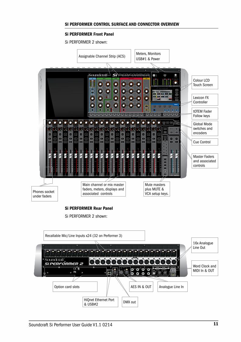
Si PERFORMER Front Panel
Si PERFORMER 2 shown:
Si PERFORMER Rear Panel
Si PERFORMER 2 shown:
SI PERFORMER CONTROL SURFACE AND CONNECTOR OVERVIEW
Meters, Monitors USB#1 & Power Assignable Channel Strip (ACS)
Colour LCD Touch Screen
Lexicon FX Controller
tOTEM Fader Follow keys
Global Mode switches and encoders
Cue Control
Master Faders and associated controls
Mute masters plus MUTE & VCA setup keys.
Main channel or mix master faders, meters, displays and associated controls
Recallable Mic/Line Inputs x24 (32 on Performer 3)
16x Analogue Line Out
Option card slots AES IN & OUT Analogue Line In
Word Clock and MIDI In & OUT
HiQnet Ethernet Port & USB#2
Phones socket under faders
DMX out
12 Soundcraft Si Performer User Guide V1.1 0214
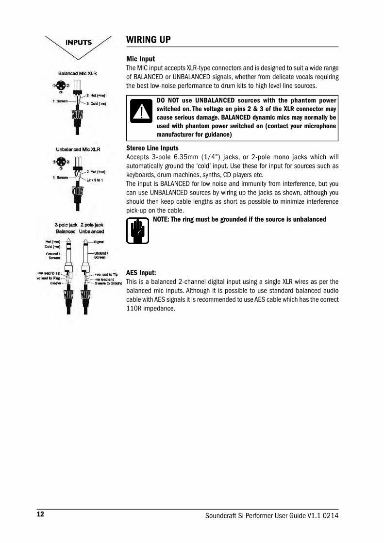
WIRING UP
Mic InputThe MIC input accepts XLR-type connectors and is designed to suit a wide range of BALANCED or UNBALANCED signals, whether from delicate vocals requiring the best low-noise performance to drum kits to high level line sources.
Stereo Line Inputs Accepts 3-pole 6.35mm (1/4") jacks, or 2-pole mono jacks which will automatically ground the ‘cold’ input. Use these for input for sources such as keyboards, drum machines, synths, CD players etc. The input is BALANCED for low noise and immunity from interference, but you can use UNBALANCED sources by wiring up the jacks as shown, although you should then keep cable lengths as short as possible to minimize interference pick-up on the cable.
NOTE: The ring must be grounded if the source is unbalanced
AES Input:This is a balanced 2-channel digital input using a single XLR wires as per the balanced mic inputs. Although it is possible to use standard balanced audio cable with AES signals it is recommended to use AES cable which has the correct 110R impedance.
DO NOT use UNBALANCED sources with the phantom power switched on. The voltage on pins 2 & 3 of the XLR connector may cause serious damage. BALANCED dynamic mics may normally be used with phantom power switched on (contact your microphone manufacturer for guidance)

13Soundcraft Si Performer User Guide V1.1 0214
Line OutputsThe 16 Line outputs are wired as shown and are fully balanced allowing long cable runs to other equipment. If connecting to un-balanced destinations the Signal – (cold) pin should be grounded.
AES Output:This is a balanced 2-channel digital output using a single XLR wired as per the balanced line outputs. Although it is possible to use standard balanced audio cable with AES signals it is recommended to use AES cable which has the correct 110R impedance.
HeadphonesThe PHONES output is a 3-pole 6.35mm (1/4”) jack, wired as a stereo output as shown, ideally for headphones of 32Ω or greater; 8Ω headphones are not recommended. The headphone socket is found under the front edge, close to fader 1.
MIDI IN & OUT This is a standard 5-pin 1800 DIN connector conforming to the MIDI standard as shown.
Word Clock75ohm BNC coaxial connector used to lock the Si PERFORMER to other digital equipment.
HiQNetStandard 100MB/s RJ45 connector used to connect the Si PERFORMER to a LAN.
Line Outputs
Aux OutputsGroup Outputs
Line Outputs
Aux OutputsGroup Outputs
FromImpedance-BalancedOutput
Signal +
Signal +
Screen
Screen
Signal -
Signal -
To External Device
To External Device
Experience has shown that sometimes it is betternot to connect screen at external device end.
Balanced Connection
Unbalanced ConnectionFromImpedance-BalancedOutput

14 Soundcraft Si Performer User Guide V1.1 0214
DMX 512 OUTDMX OUT is a 5-pin male XLR for connection to compatible devices; recommended cable impedance is 120R. The maximum cable run from first to last device is 1,200m (~3,900ft), although this may be shorter depending upon cable and connector quality and local RF environment. There should be no more than 32 devices connected to the bus without using an active splitter and a 120R terminator is normally required on the last DMX device however you should always refer to the manuals for your DMX devices for specific details and requirements.

15Soundcraft Si Performer User Guide V1.1 0214
Polarity (Phase)You will probably be familiar with the concept of polarity in electrical signals and this is of particular importance to balanced audio signals. Just as a balanced signal is highly effective at cancelling out unwanted interference, so two microphones picking up the same signal can cancel out, or cause serious degradation of the signal if one of the cables has the +ve and -ve wires reversed. This phase reversal can be a real problem when microphones are close together and you should therefore always take care to connect pins correctly when wiring audio cables.
Grounding and ShieldingFor optimum performance use balanced connections where possible and ensure that all signals are referenced to a solid, noise-free earthing point and that all signal cables have their screens connected to ground. In some unusual circumstances, to avoid earth or ground ‘loops’ ensure cable screens and other signal earths are connected to ground only at their source and not at both ends. If the use of unbalanced connections is unavoidable, you can minimise noise by following these wiring guidelines:
• On INPUTS, unbalance at the source and use a twin screened cable as though it were balanced.
• On OUTPUTS, connect the signal to the +ve output pin, and the ground of the output device to -ve. If a twin screened cable is used, connect the screen only at the mixer end.
• Avoid running audio cables or placing audio equipment close to thyristor dimmer units or power cables.
• Noise immunity is improved significantly by the use of low impedance sources, such as good quality professional microphones or the outputs from most modern audio equipment. Avoid cheaper high impedance microphones, which may suffer from interference over long cable runs, even with well-made cables.
Grounding and shielding is still seen as a black art, and the suggestions above are only guidelines. If your system still hums, an earth/ground loop is the most likely cause. Two examples of how an earth loop can occur are shown below.
Warning! Under NO circumstances must the AC power mains earth be disconnected from the mains lead.
16 Soundcraft Si Performer User Guide V1.1 0214
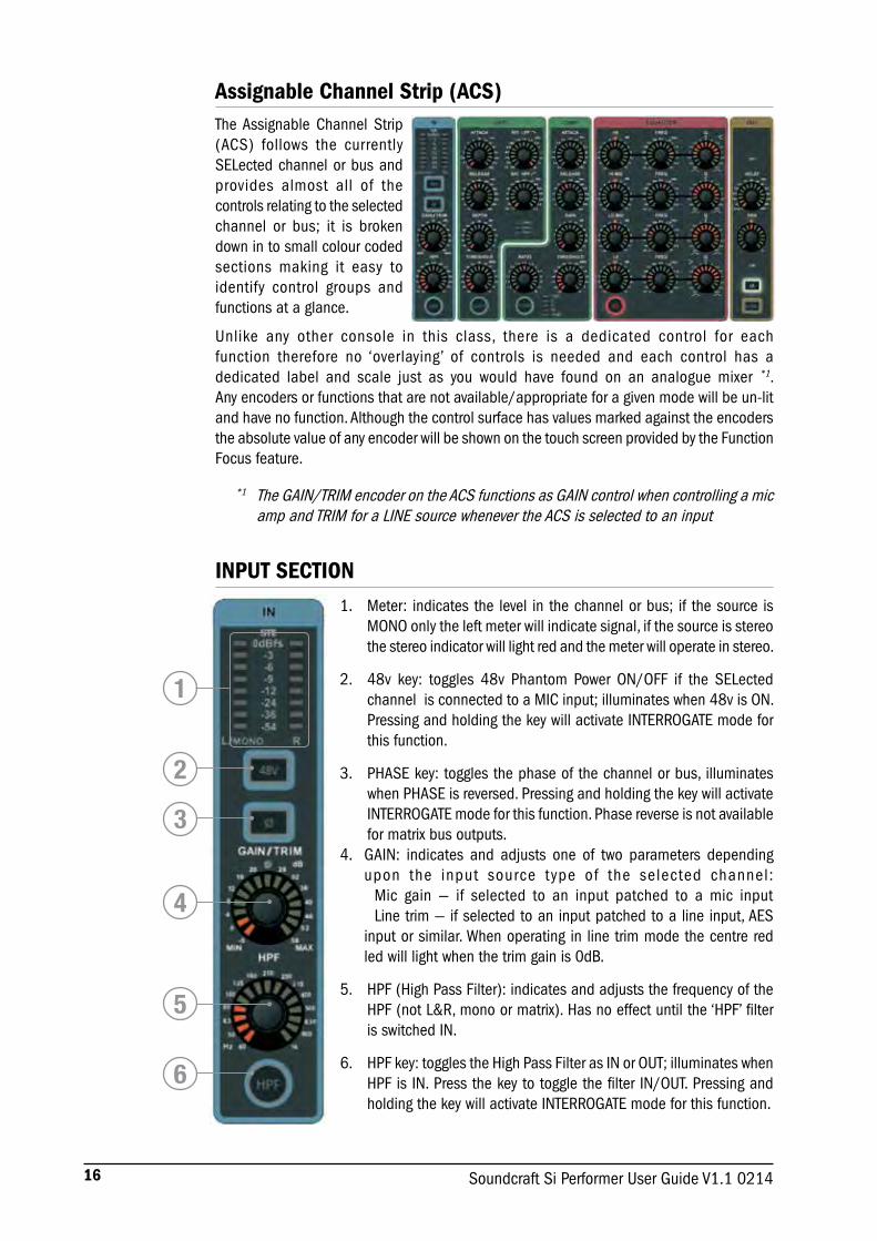
The Assignable Channel Strip (ACS) follows the currently SELected channel or bus and provides almost all of the controls relating to the selected channel or bus; it is broken down in to small colour coded sections making it easy to identify control groups and functions at a glance.
Unlike any other console in this class, there is a dedicated control for each function therefore no ‘overlaying’ of controls is needed and each control has a dedicated label and scale just as you would have found on an analogue mixer *1. Any encoders or functions that are not available/appropriate for a given mode will be un-lit and have no function. Although the control surface has values marked against the encoders the absolute value of any encoder will be shown on the touch screen provided by the Function Focus feature.
*1 The GAIN/TRIM encoder on the ACS functions as GAIN control when controlling a mic amp and TRIM for a LINE source whenever the ACS is selected to an input
INPUT SECTION1. Meter: indicates the level in the channel or bus; if the source is
MONO only the left meter will indicate signal, if the source is stereo the stereo indicator will light red and the meter will operate in stereo.
2. 48v key: toggles 48v Phantom Power ON/OFF if the SELected channel is connected to a MIC input; illuminates when 48v is ON. Pressing and holding the key will activate INTERROGATE mode for this function.
3. PHASE key: toggles the phase of the channel or bus, illuminates when PHASE is reversed. Pressing and holding the key will activate INTERROGATE mode for this function. Phase reverse is not available for matrix bus outputs.
4. GAIN: indicates and adjusts one of two parameters depending upon the input source type of the selected channel: Mic gain — if selected to an input patched to a mic input Line trim — if selected to an input patched to a line input, AES input or similar. When operating in line trim mode the centre red led will light when the trim gain is 0dB.
5. HPF (High Pass Filter): indicates and adjusts the frequency of the HPF (not L&R, mono or matrix). Has no effect until the ‘HPF’ filter is switched IN.
6. HPF key: toggles the High Pass Filter as IN or OUT; illuminates when HPF is IN. Press the key to toggle the filter IN/OUT. Pressing and holding the key will activate INTERROGATE mode for this function.
Assignable Channel Strip (ACS)
1
2
3
4
5
6

17Soundcraft Si Performer User Guide V1.1 0214
GATE SECTION1. GATE ATTACK & RELEASE: indicates and adjusts the attack
and release times of the gate.
2. GATE SC HPF/LPF: indicates & adjusts the high pass and low pass filters of the gate side chain to allow more accurate gating of signals.
3. GATE DEPTH: indicates and adjusts how many dB of attenuation the gate will apply when it is closed.
4. GATE THRESHOLD: indicates and adjusts the threshold of the gate opening/closing.
5. OPEN/HOLD/CLOSED indicators: indicate the operation of the gate:OPEN = gate is passing signal and audio is above the thresholdHOLD = gate is passing signal but audio is below the threshold, the gate will close soonCLOSED = gate is not passing signal, audio is below the threshold
6. GATE key: toggles the gate IN or OUT; illuminates when gate is IN. Press the key to toggle the gate IN/OUT. Pressing and holding the key will activate interrogate mode for this function.
NOTE: Gate function is not available on output buses.
COMPRESSOR SECTION:1. COMPRESSOR ATTACK & RELEASE: indicates and adjusts the
attack and release times of the Compressor.
2. COMPRESSOR GAIN: indicates and adjusts the gain of the compressor, is used to ‘make-up’ gain lost through compression of the signal.
3. COMPRESSOR RATIO: indicates and adjusts the compression ratio within the compressor.
4. COMPRESSOR THRESHOLD: indicates and adjusts the threshold of the compressor.
5. GAIN REDUCTION INDICATOR: indicates the amount of dB attenuation applied by the compressor.
6. COMP key: toggles the compressor IN/OUT; illuminates when compressor is IN, press the key to toggle the compressor IN/OUT. Pressing and holding the key will activate interrogate mode for this function.
3
45
1
2
1
23
456
6
18 Soundcraft Si Performer User Guide V1.1 0214
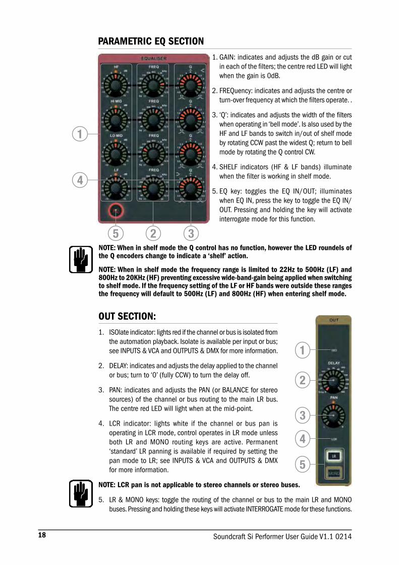
PARAMETRIC EQ SECTION1. GAIN: indicates and adjusts the dB gain or cut
in each of the filters; the centre red LED will light when the gain is 0dB.
2. FREQuency: indicates and adjusts the centre or turn-over frequency at which the filters operate. .
3. ‘Q’: indicates and adjusts the width of the filters when operating in ‘bell mode’. Is also used by the HF and LF bands to switch in/out of shelf mode by rotating CCW past the widest Q; return to bell mode by rotating the Q control CW.
4. SHELF indicators (HF & LF bands) illuminate when the filter is working in shelf mode.
5. EQ key: toggles the EQ IN/OUT; illuminates when EQ IN, press the key to toggle the EQ IN/OUT. Pressing and holding the key will activate interrogate mode for this function.
NOTE: When in shelf mode the Q control has no function, however the LED roundels of the Q encoders change to indicate a ‘shelf’ action.
NOTE: When in shelf mode the frequency range is limited to 22Hz to 500Hz (LF) and 800Hz to 20KHz (HF) preventing excessive wide-band-gain being applied when switching to shelf mode. If the frequency setting of the LF or HF bands were outside these ranges the frequency will default to 500Hz (LF) and 800Hz (HF) when entering shelf mode.
OUT SECTION:1. ISOlate indicator: lights red if the channel or bus is isolated from
the automation playback. Isolate is available per input or bus; see INPUTS & VCA and OUTPUTS & DMX for more information.
2. DELAY: indicates and adjusts the delay applied to the channel or bus; turn to ‘0’ (fully CCW) to turn the delay off.
3. PAN: indicates and adjusts the PAN (or BALANCE for stereo sources) of the channel or bus routing to the main LR bus. The centre red LED will light when at the mid-point.
4. LCR indicator: lights white if the channel or bus pan is operating in LCR mode, control operates in LR mode unless both LR and MONO routing keys are active. Permanent ‘standard’ LR panning is available if required by setting the pan mode to LR; see INPUTS & VCA and OUTPUTS & DMX for more information.
NOTE: LCR pan is not applicable to stereo channels or stereo buses.
5. LR & MONO keys: toggle the routing of the channel or bus to the main LR and MONO buses. Pressing and holding these keys will activate INTERROGATE mode for these functions.
1
4
325
1
2
3
4
5
19Soundcraft Si Performer User Guide V1.1 0214
AUDIO INTERROGATEThe Si PERFORMER offers a quick and convenient method for checking and in many cases changing the status of many parameters, this is known as ‘interrogate’.
Example #1 – To check the status of the LR routing switch from inputs to the main LR bus:
a. Select a fader bank that includes inputs.
b. Press and hold the LR routing key.
c. The SELect keys on any channels routed to LR will light.
d. While holding the LR key you may toggle the status of the LR routing on any channels or busses by pressing the SELect keys of the channels or buses you wish to include/exclude from the routing.
Interrogate operates on the following audio functions whose status may then be toggled with SELect key:
48v ON/OFF
Phase Reverse ON/OFF
HPF IN/OUT
GATE IN/OUT
COMPressor IN/OUT
EQ IN/OUT
LR routing ON/OFF
MONO routing ON/OFF
NOTE: When entering interrogate mode the status of the switch you press and hold is not changed.
VCA & MUTE INTERROGATEInterrogate may be used with the VCA and MUTE keys, pressing and holding either of these keys will flip the channel LCD names and backlight colour as appropriate and indicate to which VCA or MUTE master(s) the channel or bus is a slave.
NOTE: VCA and MUTE interrogate only allows viewing of assignments; see VCA and MUTE sections for details on how to modify the settings.
20 Soundcraft Si Performer User Guide V1.1 0214
POWER METERS AND MONITORS
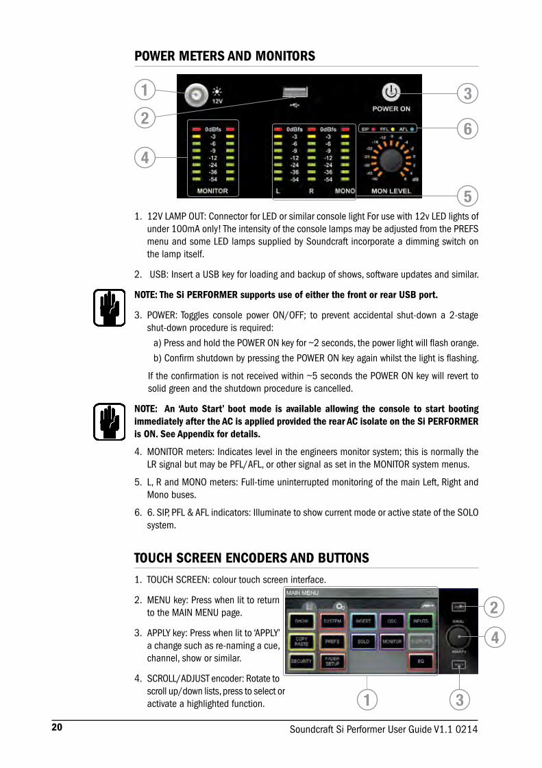
1. 12V LAMP OUT: Connector for LED or similar console light For use with 12v LED lights of under 100mA only! The intensity of the console lamps may be adjusted from the PREFS menu and some LED lamps supplied by Soundcraft incorporate a dimming switch on the lamp itself.
2. USB: Insert a USB key for loading and backup of shows, software updates and similar.
NOTE: The Si PERFORMER supports use of either the front or rear USB port.
3. POWER: Toggles console power ON/OFF; to prevent accidental shut-down a 2-stage shut-down procedure is required:
a) Press and hold the POWER ON key for ~2 seconds, the power light will flash orange.
b) Confirm shutdown by pressing the POWER ON key again whilst the light is flashing.
If the confirmation is not received within ~5 seconds the POWER ON key will revert to solid green and the shutdown procedure is cancelled.
NOTE: An ‘Auto Start’ boot mode is available allowing the console to start booting immediately after the AC is applied provided the rear AC isolate on the Si PERFORMER is ON. See Appendix for details.
4. MONITOR meters: Indicates level in the engineers monitor system; this is normally the LR signal but may be PFL/AFL, or other signal as set in the MONITOR system menus.
5. L, R and MONO meters: Full-time uninterrupted monitoring of the main Left, Right and Mono buses.
6. 6. SIP, PFL & AFL indicators: Illuminate to show current mode or active state of the SOLO system.
1
4
3
6
5
2
TOUCH SCREEN ENCODERS AND BUTTONS1. TOUCH SCREEN: colour touch screen interface.
2. MENU key: Press when lit to return to the MAIN MENU page.
3. APPLY key: Press when lit to ‘APPLY’ a change such as re-naming a cue, channel, show or similar.
4. SCROLL/ADJUST encoder: Rotate to scroll up/down lists, press to select or activate a highlighted function.
2
1 3
4

21Soundcraft Si Performer User Guide V1.1 0214
LEXICONTM INTERFACE
1. LEXicon key: press to open the Lexicon menu pages.
2. Lexicon encoders (x4): used to adjust the parameters within an effect. The encoders are context dependent upon what is shown on the touch screen at any given time.
3. TAP keys (x4): used to set the tempo of any of the patch using delays/measures; the keys flash with the set tempo.
4. SCROLL/ADJUST encoder: used to navigate between processors, pressing the encoder allows a different patch to be selected from the 29 available patches:
Reverb Patches: 14 types
Delays: 7 types
Effects: 8 types including Chorus, Flanger, Phaser and Rotary
5. PAGE TABS: used to navigate through parameters available in the selected patch; tabs 2 and 3 are greyed out as appropriate if there are no parameters on those tabs.
NOTE: Pressing the FX key while COPY/PASTE is active will enter the FX copy/paste mode; see COPY/PASTE for more details.
21 3
45
22 Soundcraft Si Performer User Guide V1.1 0214
tOTEM™ (THE ONE TOUCH EASY MIX) KEYS
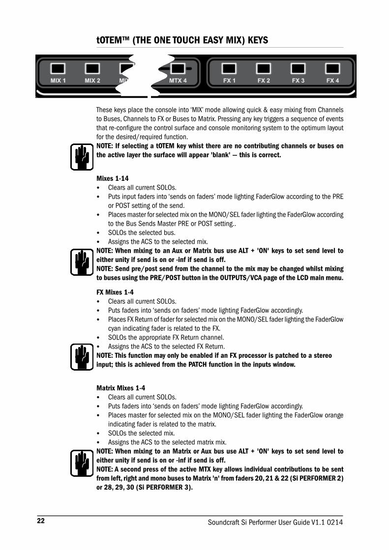
These keys place the console into ‘MIX’ mode allowing quick & easy mixing from Channels to Buses, Channels to FX or Buses to Matrix. Pressing any key triggers a sequence of events that re-configure the control surface and console monitoring system to the optimum layout for the desired/required function.NOTE: If selecting a tOTEM key whist there are no contributing channels or buses on the active layer the surface will appear 'blank' — this is correct.
Mixes 1-14• Clears all current SOLOs.• Puts input faders into ‘sends on faders’ mode lighting FaderGlow according to the PRE
or POST setting of the send.• Places master for selected mix on the MONO/SEL fader lighting the FaderGlow according
to the Bus Sends Master PRE or POST setting..• SOLOs the selected bus.• Assigns the ACS to the selected mix.NOTE: When mixing to an Aux or Matrix bus use ALT + 'ON' keys to set send level to either unity if send is on or -inf if send is off.NOTE: Send pre/post send from the channel to the mix may be changed whilst mixing to buses using the PRE/POST button in the OUTPUTS/VCA page of the LCD main menu.
FX Mixes 1-4• Clears all current SOLOs.• Puts faders into ‘sends on faders’ mode lighting FaderGlow accordingly.• Places FX Return of fader for selected mix on the MONO/SEL fader lighting the FaderGlow
cyan indicating fader is related to the FX. • SOLOs the appropriate FX Return channel.• Assigns the ACS to the selected FX Return.NOTE: This function may only be enabled if an FX processor is patched to a stereo input; this is achieved from the PATCH function in the inputs window.
Matrix Mixes 1-4• Clears all current SOLOs.• Puts faders into ‘sends on faders’ mode lighting FaderGlow accordingly.• Places master for selected mix on the MONO/SEL fader lighting the FaderGlow orange
indicating fader is related to the matrix.• SOLOs the selected mix.• Assigns the ACS to the selected matrix mix.NOTE: When mixing to an Matrix or Aux bus use ALT + 'ON' keys to set send level to either unity if send is on or -inf if send is off. NOTE: A second press of the active MTX key allows individual contributions to be sent from left, right and mono buses to Matrix 'n' from faders 20, 21 & 22 (Si PERFORMER 2) or 28, 29, 30 (Si PERFORMER 3).

23Soundcraft Si Performer User Guide V1.1 0214
GLOBAL MODE ENCODERS AND FUNCTIONS
The Global Mode encoders offer control of a key parameter across all channels or buses currently active on the surface:
1. GLOBAL ‘GAIN/TRIM’ key: press to make all the encoders function as the input GAIN (or TRIM for line & digital sources) for all the channels on the currently active fader layer. When operating as line trims the centre red LED will light when the trim gain is 0dB.
NOTE: This key has no function in BUS or MATRIX modes.
2. GLOBAL ‘FILT’ key: press to make all the encoders function as the input HPF for all the channels on the currently active input fader layer.
NOTE: This key has no function in MATRIX mode.
3. GLOBAL ‘PAN’ key: press to make all the encoders function as the PAN for all the channels or buses on the channels on the currently active fader layer. The centre red LED will light when the pan is at the mid-point.
NOTE: This key has no function in MATRIX mode.
NOTE: When mixing to a stereo bus using the tOTEM follow keys the global encoders will switch to PAN mode and shall act as the PAN or BALANCE control from the channels to the bus.
1 2 3
24 Soundcraft Si Performer User Guide V1.1 0214
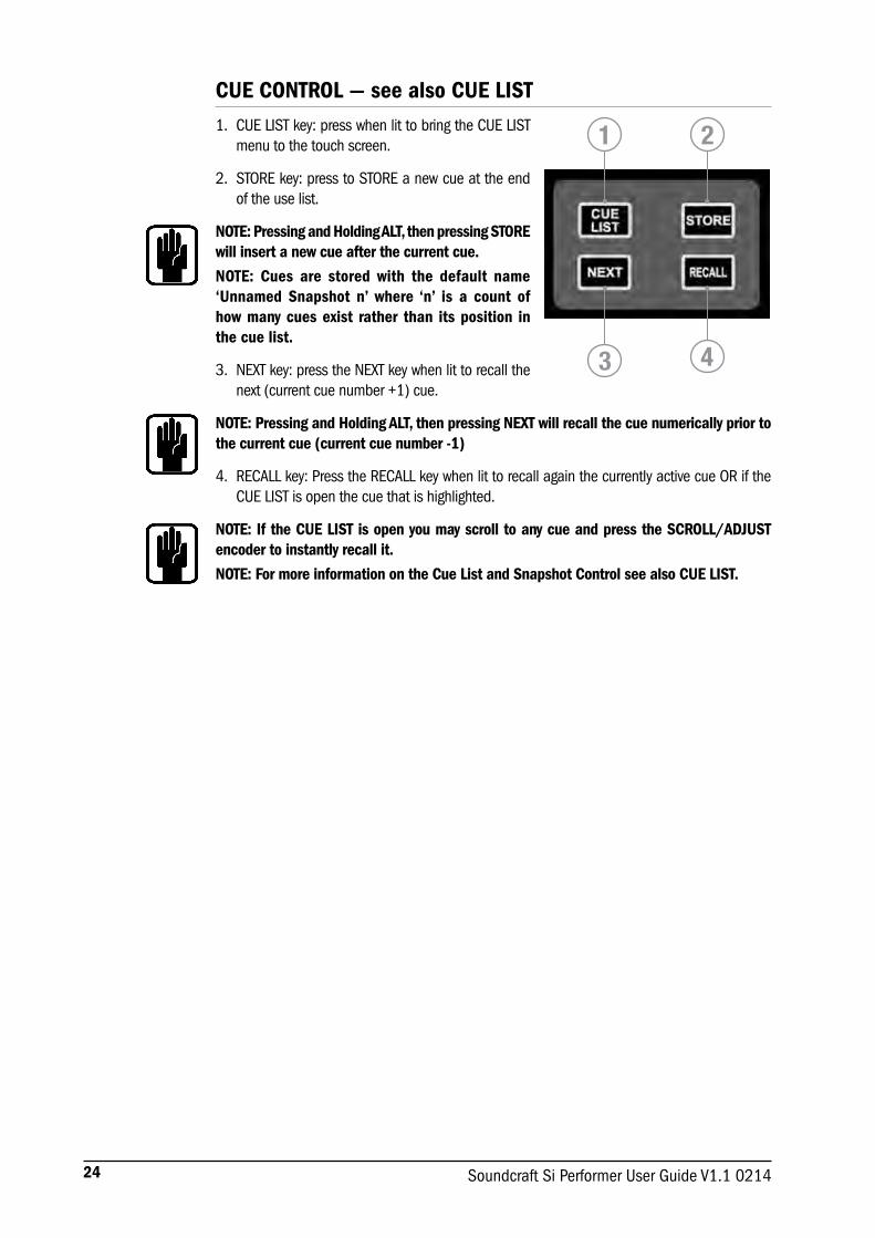
CUE CONTROL — see also CUE LIST1. CUE LIST key: press when lit to bring the CUE LIST
menu to the touch screen.
2. STORE key: press to STORE a new cue at the end of the use list.
NOTE: Pressing and Holding ALT, then pressing STORE will insert a new cue after the current cue.
NOTE: Cues are stored with the default name ‘Unnamed Snapshot n’ where ‘n’ is a count of how many cues exist rather than its position in the cue list.
3. NEXT key: press the NEXT key when lit to recall the next (current cue number +1) cue.
NOTE: Pressing and Holding ALT, then pressing NEXT will recall the cue numerically prior to the current cue (current cue number -1)
4. RECALL key: Press the RECALL key when lit to recall again the currently active cue OR if the CUE LIST is open the cue that is highlighted.
NOTE: If the CUE LIST is open you may scroll to any cue and press the SCROLL/ADJUST encoder to instantly recall it.
NOTE: For more information on the Cue List and Snapshot Control see also CUE LIST.
1 2
3 4

25Soundcraft Si Performer User Guide V1.1 0214
ALT KEYALT is a modifier key used by the following functions:FADER LAYERS A/B/C/D CLR (CLeaR function) CUE CONTROL MIXING to AUX BUSES MIXING to MATRIX BUSES
Refer to these sections for detail on the operation and use.
CLR & SOLO CLR KEYS – see also CLEAR1. CLR key: used to reset channels, buses or groups of
parameters to their factory defaults as follows:• CLR + channel or bus SELect will reset all audio
parameters within that channel or bus. to the factory defaults.
• CLR + function key within the ACS (such as EQ, GATE or COMP) will reset all assocaited parameters of the selected channel or bus to the factory defaults.
• CLR + GEQ HI or LO will reset all bands in an active GEQ to 0dB
• CLR+ tOTEM mix key will reset all contributions and ON status from channels or buses to the BUS/MTX/FX’n’ back to the factory defaults
• CLR + Mute Master 1-8 whilst in MUTE or VCA setup mode will clear the slaves to that mute or VCA master.
NOTE: The reset refers only to the main audio parameters and does not affect functions such as SOLO, bus type, names patching and mute assignment.
CAUTION: ALT+ CLR+ function key within the ACS (such as EQ, GATE or COMP) will reset all associated parameters on all channels to the factory defaults.
2. SOLO CLR: Pressing this key when lit will clear all active PFL or AFL selections.
1
2
26 Soundcraft Si Performer User Guide V1.1 0214
MUTE & MUTE MASTER KEYS
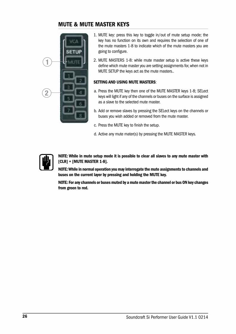
1. MUTE key: press this key to toggle in/out of mute setup mode; the key has no function on its own and requires the selection of one of the mute masters 1-8 to indicate which of the mute masters you are going to configure.
2. MUTE MASTERS 1-8: while mute master setup is active these keys define which mute master you are setting assignments for, when not in MUTE SETUP the keys act as the mute masters..
SETTING AND USING MUTE MASTERS:
a. Press the MUTE key then one of the MUTE MASTER keys 1-8; SELect keys will light if any of the channels or buses on the surface is assigned as a slave to the selected mute master.
b. Add or remove slaves by pressing the SELect keys on the channels or buses you wish added or removed from the mute master.
c. Press the MUTE key to finish the setup.
d. Active any mute mater(s) by pressing the MUTE MASTER keys.
NOTE: While in mute setup mode it is possible to clear all slaves to any mute master with [CLR] + [MUTE MASTER 1-8].
NOTE: While in normal operation you may interrogate the mute assignments to channels and buses on the current layer by pressing and holding the MUTE key.
NOTE: For any channels or buses muted by a mute master the channel or bus ON key changes from green to red.
1
2

27Soundcraft Si Performer User Guide V1.1 0214
VCA SETUPThe VCA setup is enabled by pressing the VCA key, it then uses the mute masters in conjunction with input channel SELect keys to configure input channels as slaves to a VCA master.
1. VCA key: press this key to toggle in/out of VCA setup mode; the key has no function on its own and requires the selection of one of the mute masters 1-8 to indicate which of the eight VCA masters you are going to setup.
2. MUTE MASTERS 1-8: whilst in VCA setup these keys define which VCA master you are setting assignments for.
SETTING AND USING VCA MASTERS:
a. Press the VCA key then one of the MUTE MASTER keys (1-8); SELect keys will light if any of the channels on the surface is assigned as a slave to the selected VCA master.
b. Add or remove slaves by pressing the SELect keys on the channels you wish added or removed from the VCA master.
c. Press the VCA key to finish the setup.
NOTE: While in setup mode it is possible to clear all slaves to any VCA master with [CLR] + [MUTE MASTER 1-8].
NOTE: While in normal operation you may interrogate the VCA assignments to channels on the current layer by pressing and holding the VCA key.
NOTE: For any channels muted by a VCA master the ON key changes from green to red.
1
2

28 Soundcraft Si Performer User Guide V1.1 0214
MASTER LR FADER AND ASSOCIATED KEYS1. MASTER LR fader: sets the overall level of the main Left & Right bus out.
2. MASTER LR ON key: toggles the main left and right bus ON/OFF.
3. MASTER SELect key: assigns (SELects) the ACS to the main left and right buses.
MONO/SEL FADER AND ASSOCIATED KEYS1. MONO/SEL fader: sets the overall level of the MONO bus out unless::
• FADER FOLLOW 1-14 or MTX1-4 active - Fader is the master level for MIX / MTX ‘n’..
• FX FOLLOW 1-4 active - Fader is the channel level of FX Return channel ‘n’• Fader Layer [ALT A/B/C/D] active – Fader is the DMX master A/B/C/D
2. MONO ON key: Toggles the MONO bus ON/OFF unless:• FADER FOLLOW MIX 1-14 or MTX1-4 active - ON is the master ON/OFF
level for MIX / MTX‘n’.• FX FOLLOW 1-4 active – ON is the ON/OFF for FX Return channel ‘n’• Fader Layer [ALT A/B/C/D] active – ON is the ‘FLASH’ function key for DMX
master A/B/C/D.
3. MONO SELect key: Assigns (SELects) the ACS Channel to the MONO bus unless:• FADER FOLLOW 1-14 or MTX1-4 active – SELects mix or matrix master ‘n’
to the ACS.• FX FOLLOW 1-4 active – SELects FX Return channel ‘n’ to the ACS.• Fader Layer [ALT A/B/C/D] active – Focus LCD to DMX master A/B/C/D -
context dependant on active LCD screen mode.
23
1
23
1

29Soundcraft Si Performer User Guide V1.1 0214
FADER LAYER KEYSFader Layer Keys change the function of the faders to the left of the master faders:
1. A: Layer ‘A’, nominally inputs.
2. B: Layer ‘B’, nominally inputs.
3. C: Layer ‘C’, nominally bus masters and VCA masters.
4. D: Layer ‘D’, nominally Matrix Masters.
5. GEQ LO: The lower half of the GEQ.
6. GEQ HI: The upper half of the GEQ.
NOTE: The GEQ pages are only available when an audio master fader is SELected.
To access the DMX controller fader layers press and hold the [ALT] key plus A/B/C/D. Whilst on a DMX layer the fader layer keys are lit orange and the DMX master for the active layer (A-D) is assigned to the MONO/SEL fader.
To return to the main A/B/C/D layers press the active (lit) DMX layer key or press and hold [ALT] plus A/B/C/D.
1
2
3
4
5
6
FADERGLOWTM
The FaderGlow™ system illuminates the fader slot when the function of the fader is anything other than ‘a mono input channel level control’ according to the following list:
Yellow: Mix 1-14 bus master nominally set as PRE fade or contribution from a channel to a mix bus sent pre-fade from the channel.
Green: Mix 1-14 bus master nominally set as POST fade or contribution from a channel to a mix bus sent post-fade from the channel.
Orange: Matrix 1-4 bus master or contribution from a bus or mix L, R or Mono to a matrix.
Red: GEQ.
Cyan: Stereo input patched as an FX return or contribution from an input to an FX mix.
Magenta: Stereo input patched to a line source other than an FX processor.
Blue: VCA bus master.
White: DMX controller fader.

30 Soundcraft Si Performer User Guide V1.1 0214
CHANNEL FADERS AND ASSOCIATED KEYS & DISPLAYS1. Global Mode Encoder & Display – See GLOBAL MODE for more detail on
this function.
2. Level Meter: indicates audio level in the channel or mix bus assigned to the fader.
3. Gain Reduction Meter: indicates gain reduction in the channel or mix bus assigned to the fader.
4. Gate Closed Indicator: Indicates the gate is closed in the input channel assigned to the fader.
5. LCD name window: displays the name assigned to the fader, the backlight colour assists in identifying the function of the channel / fader:
• White – linked input or DMX channel or DMX master
• Cyan – Stereo input patched to an FX processor
• Magenta – Stereo input not assigned to an FX processor
• Yellow – pre fade send from a channel to a mix or mix master nominally set pre-fade
• Green - post fade send from a channel to a mix or mix master nominally set post-fade
• Blue – VCA master
• Orange – Send from a mix bus to a matrix or a matrix master
• Red – GEQ band
6. ON Key: function is dependent on the channel type associated with the fader and mode active at any given time:
• Audio channel or bus – channel bus ON/OFF
• VCA group master – VCA master mute ON/OFF
• DMX master or slave – FLASH
• Follow Mode – send from channel/bus ‘n’ to mix ‘x’ ON/OFF
• GEQ Mode – resets the GEQ band gain to 0dB.
7. SELect Key: Selects the channel or mix bus to the ACS and focuses the main LCD on the SELected fader.
8. SOLO Key: Will SOLO the channel or bus; actual mode will depend upon the settings in the SOLO menu and status of other SOLO functions within the system. See SOLO MENU for more information on the solo system operation.
9. Fader: function set according to mode/setting of fader layers:
• Audio channel or bus – channel or mix / matrix master level
• VCA group master – VCA master level
• DMX master or slave – DMX channel or master level
• Follow Mode - send from channel/bus ‘n’ to mix/matrix ‘x’ level
• GEQ Mode - GEQ band gain
12
36
7
8
9
45

31Soundcraft Si Performer User Guide V1.1 0214
GEQ
The Si PERFORMER features a 28 band Graphic EQ on every mix, matrix and main master; having a GEQ on every bus means there is no need to ‘patch’ the GEQ, just enable it when required with no risk of running out of DSP.
The GEQ function is available whenever an audio mix master is SELected, at all other times the GEQ keys will have no function.
With a mix master SELected press either the GEQ HI or LO keys to open the GEQ across the 14 faders immediately left of the FADER BANK keys; the ON key will be lit red of any GEQ band not at 0dB, press the lit key to return that band gain to 0dB.
Toggle between GEQ HI & LO with the appropriate key. The frequency bands for HI and LO are shown in the LCD above each fader; the scale on the left hand side of the fader slot indicates the dB of cut or boost applied and there is the ‘Function Focus’ display on the LCD displaying a view of all the GEQ faders and the gain of the band being moved.
To manually exit the GEQ press the lit GEQ HI/LO key, Si PERFORMER will automatically exit GEQ mode if changing / activating a mix follow key, SELecting a fader that is not an audio mix master, changing layers or re-SELecting the bus to which the GEQ is currently open.
Press and hold either of the GEQ keys to toggle the GEQ in/out of ‘bypass’; while in bypass the ‘inactive’ GEQ LO/HI band key will be lit orange.
NOTE: When not in a mix follow mode it is possible to swap the GEQ between mix masters on the current layer by SELecting another master; any fader slots not used by the GEQ will remain showing the function and name associated with that fader. SELect assignments on the GEQ bands will remain as they were before the GEQ were opened.
NOTE: To reset all bands of the active GEQ press CLR together with either of the GEQ keys.

32 Soundcraft Si Performer User Guide V1.1 0214
LEXICONTM FXThe Si PERFORMER features four amazing Lexicon FX processors, each processor has it’s own dedicated bus and up to four stereo input channels may be assigned as the FX Returns;
LEXICON CONTROL:a. Press the FX key to open the LCD page on the main LEXICON
Menu allowing selection of an FX processor, changing of patch type and adjustment of parameters within the patch.
NOTE: If one of the FX Follow modes (1-4) were active the Lexicon control will ‘land’ on that FX processor when you open the FX page.
b. Press the SCROLL/ADJUST encoder to select an alternate patch type from the drop-down list.
c. Parameters for the active FX Process & Path are shown above each of the four encoders directly below the screen, these are used to adjsut the parameters values in real time
d. In the event there are more than four parameters on the current patch use the PAGE tabs to access the additional parameters
NOTE: If the chosen effect type has a TEMPO functtion the associated TAP key on the surface can be used to set the measure; the key will flash in-time with the set tempo.
NOTE: If an FX processor has no stereo channel assigned as a return then it is not possible to mix to the associated FX bus. See tOTEM and Patching for further details.
The current page
The selectedFX processor
The value ofthe parameter
The active patch

33Soundcraft Si Performer User Guide V1.1 0214
FUNCTION FOCUSFunction Focus is a feature introduced on the Soundcraft Si Compact brought into the Si PERFORMER by popular demand allowing pinpoint adjustment of any controls and settings. Whenever any active control on the surface is adjusted the appropriate function focus window opens on the LCD detailing the control you are adjusting, its name, and absolute value, additionally the function focus displays information about other associated controls and the name of the channel you are adjusting.
The ‘Function Focus’ operates for most logical groups of controls. This screen shot shows the COMPressor on channel named ‘Kick Drum’; the control being adjusted is the largest of the roundels (THRESHold), whilst all controls within the group are indicated in the smaller roundels at the bottom of the screen.
For parameters commonly expressed in different units additional roundels are displayed:
• DELAY is illustrated in ms, feet and meters (ref 20degC standard temperature & pressure)
• EQ filter width is displayed in 'Q' and 'Octaves'

34 Soundcraft Si Performer User Guide V1.1 0214
MAIN LCD SCREENSThe Soundcraft Si PERFORMER has such a versatile control surface that the colour touch screen is never required for mixing and is employed only for editing parameters like naming, channel setup and patching.
Typical main MENU screen & associated controls:
1. Title Bar – Name of the active cue on the console.
2. MENU key: Returns to main MENU page, or 'back-up' one level if in a sub menu or screen such as QWERTY or PATCHING within the INPUTS or OUTPUTS page.
NOTE: Unconfirmed data such as a name entry/edit is discarded if exiting the page via the MENU key.
3. APPLY key: Press when lit to confirm a change to name or similar.
4. SCROLL/ADJUST: Press to access editing of a parameter or confirm a list view selection, scroll to edit a parameter.
SHOW MENUThe SHOW menu manages:
• Show file save and load functions for the internal MMC (SD) card and user's USB key
• Reset Configuration
• Global Isolate filters
EDIT SHOW Menu.
12
4
3
35Soundcraft Si Performer User Guide V1.1 0214
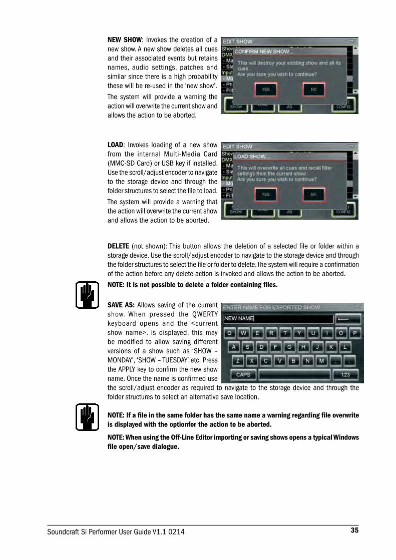
NEW SHOW: Invokes the creation of a new show. A new show deletes all cues and their associated events but retains names, audio settings, patches and similar since there is a high probability these will be re-used in the ‘new show’.
The system will provide a warning the action will overwrite the current show and allows the action to be aborted.
LOAD: Invokes loading of a new show from the internal Multi-Media Card (MMC-SD Card) or USB key if installed. Use the scroll/adjust encoder to navigate to the storage device and through the folder structures to select the file to load.
The system will provide a warning that the action will overwrite the current show and allows the action to be aborted.
DELETE (not shown): This button allows the deletion of a selected file or folder within a storage device. Use the scroll/adjust encoder to navigate to the storage device and through the folder structures to select the file or folder to delete. The system will require a confirmation of the action before any delete action is invoked and allows the action to be aborted.
NOTE: It is not possible to delete a folder containing files.
SAVE AS: Allows saving of the current show. When pressed the QWERTY keyboard opens and the <current show name>. is displayed, this may be modified to allow saving different versions of a show such as ‘SHOW – MONDAY’, ‘SHOW – TUESDAY’ etc. Press the APPLY key to confirm the new show name. Once the name is confirmed use the scroll/adjust encoder as required to navigate to the storage device and through the folder structures to select an alternative save location.
NOTE: If a file in the same folder has the same name a warning regarding file overwrite is displayed with the optionfor the action to be aborted.
NOTE: When using the Off-Line Editor importing or saving shows opens a typical Windows file open/save dialogue.

36 Soundcraft Si Performer User Guide V1.1 0214
SYSTEM MENU
The system menu home screen displays general information regarding the console, software, version, configuration and similar:
Console Name: Allows the console to be ‘personalised’ with any user information such as owner’s name, serial number, asset number or similar. Scroll to highlight the line item then ‘click’ to open the QWERTY keyboard. Selection is stored as part of the console configuration.
SYSTEM: Information about the console:• Console Type – Displays type of console, cannot be edited. • Software Version – Current software version, cannot be edited. • Date - Current date, select & ‘click’ to edit. • Time - Current date, select & ‘click’ to edit.
CLOCKING: Select from INTernal or EXTernal word clock – See ‘Word Clock’. When set to EXTernal an icon is displayed on the LCD screen:
If incoming word clock is OK.
If incoming clock is lost, or out of range.
EDIT SHOW – Global Recall Isolate: Prevents the automation recalling isolated parameters (or groups of parameters) when a cue is replayed; scroll to the desired list item, press the encoder and select Isolate.
Parameters are logically grouped as:• DMX Recall Isolate• Input Recall Isolate • Bus Recall Isolate • Matrix Recall Isolate • Output GEQ Isolate • Patching Recall Isolate • Lexicon Recall Isolate • VCA Recall Isolate.• Master Recall Isolate
NOTE: When storing a cue all audio parameters are stored regardless of any ISO to be ‘isolated’ from the automation.
RESET CONFIG: Clears the console database of any option cards or external I/O systems that may have been attached to the console. Reset config also forces a ‘re-discovery’ of any installed option cards or connected I/O system such as a Soundcraft Stagebox; see I/O Discovery for further details. The system will provide a warning that the action will overwrite the current configuration database and allow the action to be aborted

37Soundcraft Si Performer User Guide V1.1 0214
NETWORK: Information and settings regarding Ethernet connectivity:• MAC Address – Displays MAC
address of console, cannot be edited.
• IP Address Resolution – Toggles between MANUAL or DHCP for setting the console IP address.
• IP Address – Allows manual setting of the IP address.
• Subnet Mask – Allows manual setting of the subnet mask.
NOTE: Address and Subnet can only be edited in MANUAL mode.NOTE: Console must be rebooted for IP address change to take effect
HiQnet: Information and settings regarding HiQnet connectivity:• HiQnet – Toggles HiQnet functionality Enabled/Disabled• HiQnet Address – Allows setting of the console HiQnet address
NOTE: Clocking, Network & HiQnet settings are stored as part of the console configuration.
NOTE: A console reboot is required for IP Address, Subnet Mask and HiQnet to take effect.
RESET CHANNELS: Resets all Input Channel audio parameters, channel name and channel type (MONO/LINKED) to factory default.
NOTE: Patching is excluded from Reset Channels
RESET BUSES: Resets all audio parameters of all mix buses 1-14, bus name and bus type (mono/stereo) to factory default.
NOTE: Patching is excluded from Reset Buses
RESET PATCHING: Resets all system patching to factory default.
RESET ALL: Resets all parameters including names and patches to factory default.
NOTE: With all RESET menus a confirm dialogue is provided allowing the action to be cancelled.
38 Soundcraft Si Performer User Guide V1.1 0214
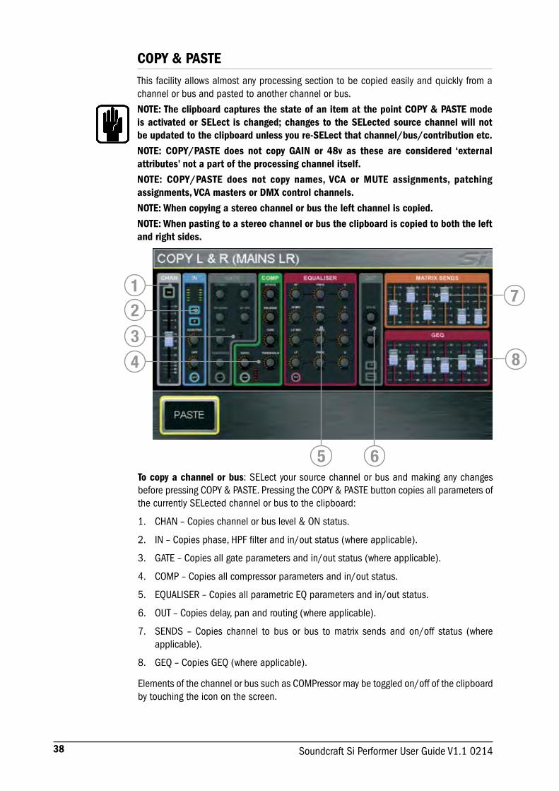
COPY & PASTEThis facility allows almost any processing section to be copied easily and quickly from a channel or bus and pasted to another channel or bus.
NOTE: The clipboard captures the state of an item at the point COPY & PASTE mode is activated or SELect is changed; changes to the SELected source channel will not be updated to the clipboard unless you re-SELect that channel/bus/contribution etc.
NOTE: COPY/PASTE does not copy GAIN or 48v as these are considered ‘external attributes’ not a part of the processing channel itself.
NOTE: COPY/PASTE does not copy names, VCA or MUTE assignments, patching assignments, VCA masters or DMX control channels.
NOTE: When copying a stereo channel or bus the left channel is copied.
NOTE: When pasting to a stereo channel or bus the clipboard is copied to both the left and right sides.
To copy a channel or bus: SELect your source channel or bus and making any changes before pressing COPY & PASTE. Pressing the COPY & PASTE button copies all parameters of the currently SELected channel or bus to the clipboard:
1. CHAN – Copies channel or bus level & ON status.
2. IN – Copies phase, HPF filter and in/out status (where applicable).
3. GATE – Copies all gate parameters and in/out status (where applicable).
4. COMP – Copies all compressor parameters and in/out status.
5. EQUALISER – Copies all parametric EQ parameters and in/out status.
6. OUT – Copies delay, pan and routing (where applicable).
7. SENDS – Copies channel to bus or bus to matrix sends and on/off status (where applicable).
8. GEQ – Copies GEQ (where applicable).
Elements of the channel or bus such as COMPressor may be toggled on/off of the clipboard by touching the icon on the screen.
1234
5 6
7
8

39Soundcraft Si Performer User Guide V1.1 0214
To select a single item such as EQ press and hold the EQ icon to toggle all other items off.
To paste the clipboard contents to another channel or bus press and hold the PASTE button while pressing the SEL keys of the desired destination channels.
Copy sends from all channels to bus’n’: Pressing COPY & PASTE while in FOLLOW mode or changing to FOLLOW mode while in COPY & PASTE will copy to the clipboard bus send levels and ON/OFF from all channels to bus ‘n’. To paste the contributions from to another bus press and hold the PASTE button while pressing MIX’n’ key(s) of the destination mixes.
Copy Lexicon settings between processors: Pressing the FX key while in COPY & PASTE mode will display icons for all Lexicon processors; select the source processor by touching it’s icon. To paste the processor press and hold the PASTE button while pressing FX’n’ keys of the destination processors.
40 Soundcraft Si Performer User Guide V1.1 0214
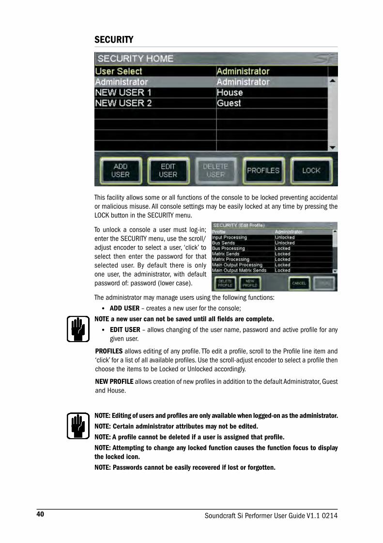
SECURITY
This facility allows some or all functions of the console to be locked preventing accidental or malicious misuse. All console settings may be easily locked at any time by pressing the LOCK button in the SECURITY menu.
To unlock a console a user must log-in; enter the SECURITY menu, use the scroll/adjust encoder to select a user, ‘click’ to select then enter the password for that selected user. By default there is only one user, the administrator, with default password of: password (lower case).
The administrator may manage users using the following functions:
• ADD USER – creates a new user for the console;
NOTE a new user can not be saved until all fields are complete.
• EDIT USER – allows changing of the user name, password and active profile for any given user.
PROFILES allows editing of any profile. TTo edit a profile, scroll to the Profile line item and ‘click’ for a list of all available profiles. Use the scroll-adjust encoder to select a profile then choose the items to be Locked or Unlocked accordingly.
NEW PROFILE allows creation of new profiles in addition to the default Administrator, Guest and House.
NOTE: Editing of users and profiles are only available when logged-on as the administrator.
NOTE: Certain administrator attributes may not be edited.
NOTE: A profile cannot be deleted if a user is assigned that profile.
NOTE: Attempting to change any locked function causes the function focus to display the locked icon.
NOTE: Passwords cannot be easily recovered if lost or forgotten.
41Soundcraft Si Performer User Guide V1.1 0214
PREFS (USER PREFERENCES)This menu allows certain ‘operational characteristics’ of the console to be edited. Parameters that may be adjusted are:
• LED brightness – brightness of meters and encoder roundels
• BUTON brightness – brightness of LEDs behind rubber key buttons
• FaderGlow™ brightness – brightness of FaderGlow™ bars
• Screen brightness – brightness of LCD backlight
• Channel LCD brightness – brightness of channel name LCD
• Channel LCD contrast – contrast of channel name LCD
• D.O.G.S. (Direct Out Gain Stabiliser) – Sets D.O.G.S. ON/OFF. See D.O.G.S. for more details of this function.
D.O.G.S.D.O.G.S. (Direct Out Gain Stabiliser) is a tool to help maintain stored gain structure between channel input and direct output when multiple devices are sharing a single source.
When enabled, D.O.G.S. adjusts the direct output level from each channel inversely to any manual change of a mic gain control (across a change of +16/-10dB) on that channel. This allows the channel direct outputs to feed to a second console, recording system or similar device with the feed to the 2nd device effectively isolated from a user changing the gain control.
The D.O.G.S. facility is turned ON/OFF globally from the PREFS menu with the offset cleared each time a cue is recalled or the D.O.G.S. function is turned off. For more information refer to the White Paper section of the Soundcraft web site
NOTE: DOGS operates on a cue-by-cue basis against any manual adjustment to mic amp gain, it is not an offset that offset that ripples through to subsequent uses.
CAUTION: When disabling DOGS any offsets are reset which may result in an increase/decrease in level on any systems fed from the Si PERFORMER direct outputs.
NOTE: DOGS is intended for use live, DOGS offsets are NOT stored with any cue or cue update.

42 Soundcraft Si Performer User Guide V1.1 0214
FADER SETUP
The fader setup provides a mean to define which channels (or buses) appear on which faders of which layers.
This feature allows almost any channel, bus or controller fader such as VCA master or DMX master to be moved between layers, it is accessed from the FADER SETUP menu; there are essentially two elements to this, making new assignments and moving assignments. .
Making a new assignment or changing a current assignment in the SELected slot.
The FADER SETUP page displays two fixed data fields of:
• Fader Bank – Current active fader bank
• Slot Number – which slot (position) has the SELect active
The following fields group the available processing channels, buses and controllers allowing easy selection of the channel bus or controller you wish to assign to the SELected slot, selecting any field will offer a drop-down list as follows:
• Assign Mono Input – All 64 mono processing channels
• Assign Stereo Inputs - All 8 stereo processing channels
• Assign Mixes – All 14 mix bus masters
• Assign MTX – All 4 matrix bus masters
• Assign VCA – All 8 VCA group masters
• Assign DMX – All 4 DMX masters
NOTE: Once a drop-down list is open a selection must be made.
NOTE: All lists offer an ‘Unassigned’ option.
NOTE: With the fader assign page open you may use change fader layers and SELect to rapidly reassign other faders.

43Soundcraft Si Performer User Guide V1.1 0214
Moving assignments on the active layer.
There are two types of functions that assist in re-ordering faders on a layer INSERT BLANK and SHIFT each with a << (left) or >> (right) option, these functions are similar but subtly different.
• INSERT BLANK will insert a blank (unassigned) fader in the SELected slot and move all other assignments left (right).
• SHIFT allows an assigned fader to be moved up (down) provided the adjacent slot is unassigned.
The current active fader layer may be reset to the factory default using the RESET LAYER button.
NOTE: Fader assignments are stored per show.
NOTE: The assignments of the L&R and MONO/SEL faders may not be changed.
NOTE: It is possible for the surface to appear to ‘blank’ if a mix follow key is activated and there are no contribution channel types to that mix type on that active layer – this is correct and normal behavior.
NOTE: The same control fader may be placed a maximum of twice on any layer.

44 Soundcraft Si Performer User Guide V1.1 0214
INSERT
Four insert patches are available, inserts are assignable to:
• Mono and Stereo inputs - Pre EQ
• Mixes 1-14 – Pre EQ, Post EQ or Post-fade
• LR, Mono and Matrix 1-4 - Pre EQ, Post EQ
The inserts are configured from the INSERT SETUP button found on the INSERT screen. For insert sends, any line out or digital out channel may be used and for insert returns any line in or digital input may be used; once .
NOTE: If an insert and input or bus uses the same patch the insert requirement will over-ride the input or bus patch request however the input or bus will still show the original patch.
NOTE: The insert patch system will always present the 128 option slot inputs (slot 1 digital in 1-64 and digital in 64-128) and 96 option slot outputs (slot 1 digital out 1-64 and digital out 65-96)
45Soundcraft Si Performer User Guide V1.1 0214
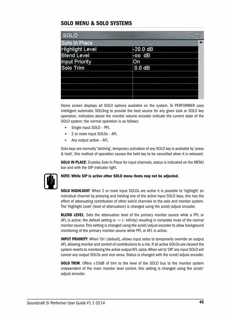
SOLO MENU & SOLO SYSTEMS
Home screen displays all SOLO options available on the system. Si PERFORMER uses intelligent automatic SOLOing to provide the best source for any given task or SOLO key operation; indicators above the monitor volume encoder indicate the current state of the SOLO system; the normal operation is as follows:
• Single input SOLO – PFL
• 2 or more input SOLOs – AFL
• Any output active – AFL
Solo keys are normally ‘latching’, temporary activation of any SOLO key is available by ‘press & hold’, this method of operation causes the held key to be cancelled when it is released.
SOLO IN PLACE: Enables Solo In Place for input channels, status is indicated on the MENU bar and with the SIP indicator light.
NOTE: While SIP is active other SOLO menu items may not be adjusted.
SOLO HIGHLIGHT: When 2 or more input SOLOs are active it is possible to ‘highlight’ an individual channel by pressing and holding one of the active input SOLO keys, this has the effect of attenuating contribution of other solo’d channels to the solo and monitor system. The ‘Highlight Level’ (level of attenuation) is changed using the scroll/adjust encoder.
BLEND LEVEL: Sets the attenuation level of the primary monitor source while a PFL or AFL is active; the default setting is -∞ (- infinity) resulting in complete mute of the normal monitor source. This setting is changed using the scroll/adjust encoder to allow background monitoring of the primary monitor source while PFL or AFL is active.
INPUT PRIORITY: When ‘On’ (default), allows input solos to temporarily override an output AFL allowing monitor and control of contributions to a mix. If all active SOLOs are cleared the system reverts to monitoring the active output AFL solos. When set to ‘Off’ any input SOLO will cancel any output SOLOs and vice versa. Status is changed with the scroll/adjust encoder.
SOLO TRIM: Offers ±10dB of trim to the level of the SOLO bus to the monitor system independent of the main monitor level control, this setting is changed using the scroll/adjust encoder.
46 Soundcraft Si Performer User Guide V1.1 0214
OSC MENU
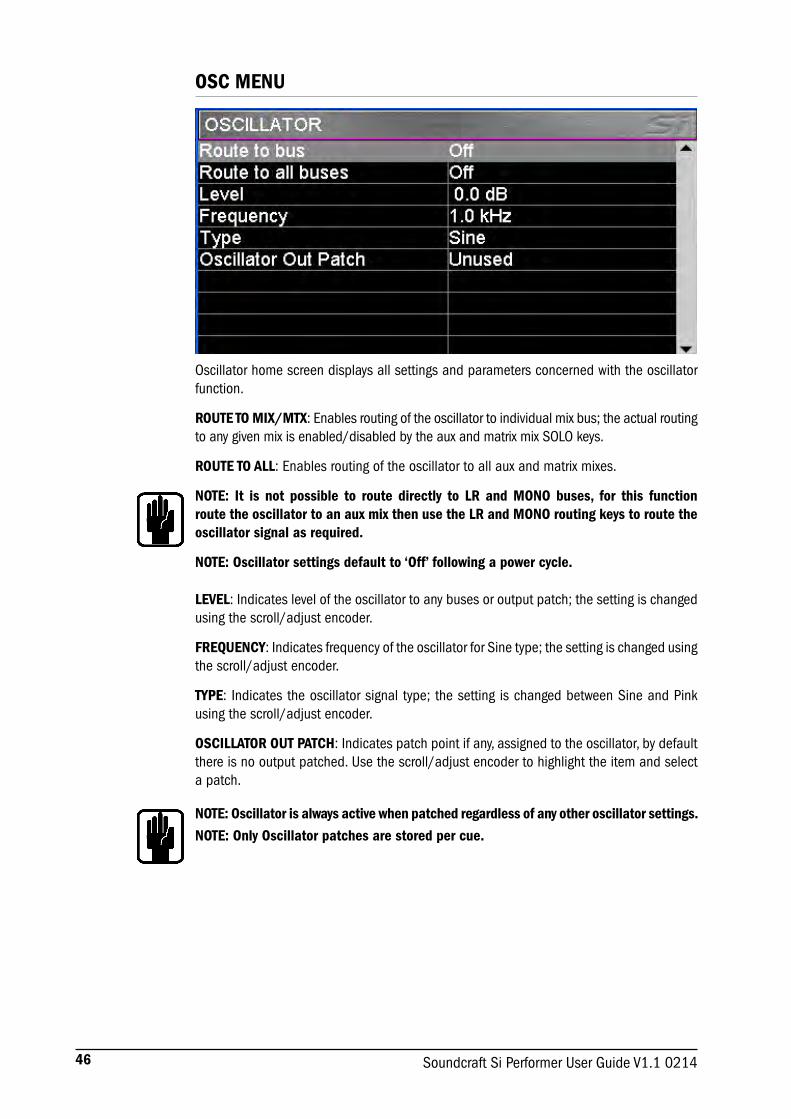
Oscillator home screen displays all settings and parameters concerned with the oscillator function.
ROUTE TO MIX/MTX: Enables routing of the oscillator to individual mix bus; the actual routing to any given mix is enabled/disabled by the aux and matrix mix SOLO keys.
ROUTE TO ALL: Enables routing of the oscillator to all aux and matrix mixes.
NOTE: It is not possible to route directly to LR and MONO buses, for this function route the oscillator to an aux mix then use the LR and MONO routing keys to route the oscillator signal as required.
NOTE: Oscillator settings default to ‘Off’ following a power cycle.
LEVEL: Indicates level of the oscillator to any buses or output patch; the setting is changed using the scroll/adjust encoder.
FREQUENCY: Indicates frequency of the oscillator for Sine type; the setting is changed using the scroll/adjust encoder.
TYPE: Indicates the oscillator signal type; the setting is changed between Sine and Pink using the scroll/adjust encoder.
OSCILLATOR OUT PATCH: Indicates patch point if any, assigned to the oscillator, by default there is no output patched. Use the scroll/adjust encoder to highlight the item and select a patch.
NOTE: Oscillator is always active when patched regardless of any other oscillator settings.
NOTE: Only Oscillator patches are stored per cue.

47Soundcraft Si Performer User Guide V1.1 0214
MONITOR MENUThe MONITOR menu provides information to all parameters and functions concerning the monitor system and outputs.
L&R monitor Speakers: Enables or disables the Monitor Out patch.
Mono Check: Creates a mono sum of the signal in the monitors.
Delay: Enables or disables the output delay to the monitor output patch.
Delay Time: Adjusts the delay time applied to the monitor outputs.
Monitor L&R Out Patch: Allows the stereo monitor signal to be patched to any pair of system outputs in addition to the monitor signal being routed to the headphones; see PATCHING for details of the system patching functionality
48 Soundcraft Si Performer User Guide V1.1 0214
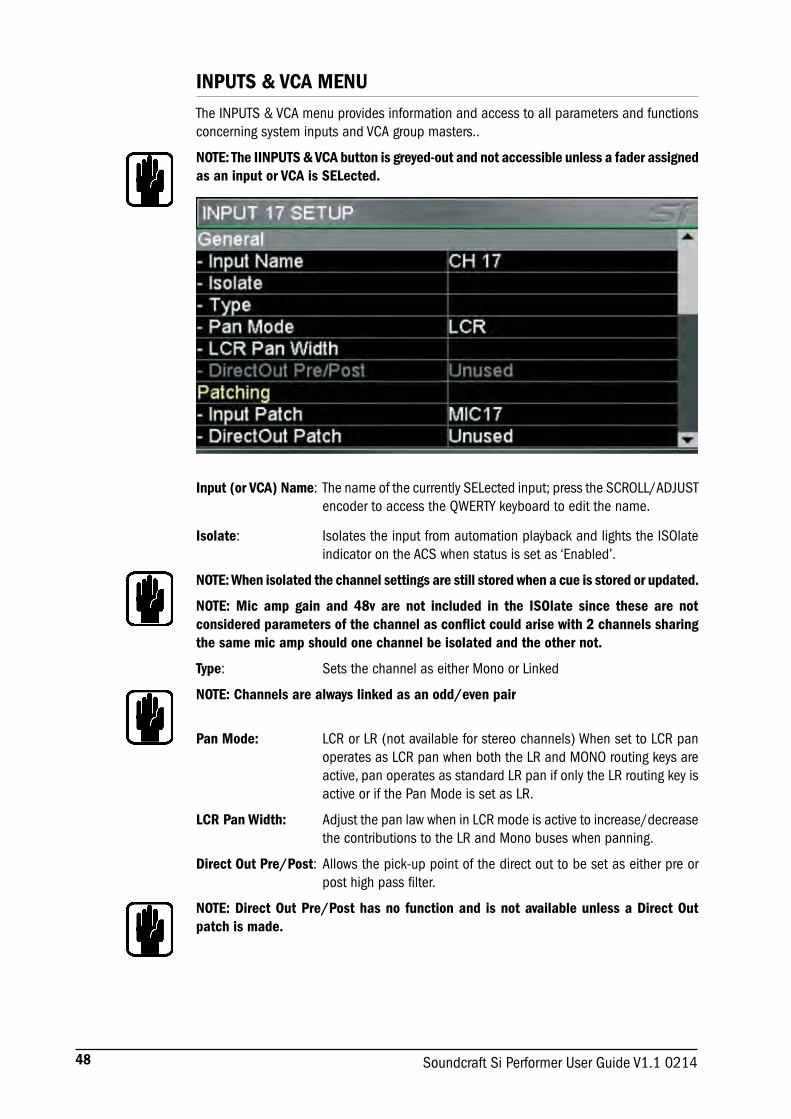
INPUTS & VCA MENUThe INPUTS & VCA menu provides information and access to all parameters and functions concerning system inputs and VCA group masters..
NOTE: The IINPUTS & VCA button is greyed-out and not accessible unless a fader assigned as an input or VCA is SELected.
Input (or VCA) Name: The name of the currently SELected input; press the SCROLL/ADJUST
encoder to access the QWERTY keyboard to edit the name.
Isolate: Isolates the input from automation playback and lights the ISOlate indicator on the ACS when status is set as ‘Enabled’.
NOTE: When isolated the channel settings are still stored when a cue is stored or updated.
NOTE: Mic amp gain and 48v are not included in the ISOlate since these are not considered parameters of the channel as conflict could arise with 2 channels sharing the same mic amp should one channel be isolated and the other not.
Type: Sets the channel as either Mono or Linked
NOTE: Channels are always linked as an odd/even pair
Pan Mode: LCR or LR (not available for stereo channels) When set to LCR pan operates as LCR pan when both the LR and MONO routing keys are active, pan operates as standard LR pan if only the LR routing key is active or if the Pan Mode is set as LR.
LCR Pan Width: Adjust the pan law when in LCR mode is active to increase/decrease the contributions to the LR and Mono buses when panning.
Direct Out Pre/Post: Allows the pick-up point of the direct out to be set as either pre or post high pass filter.
NOTE: Direct Out Pre/Post has no function and is not available unless a Direct Out patch is made.

49Soundcraft Si Performer User Guide V1.1 0214
Input Patch: Displays the source patched to the channel; see PATCHING for details of the system patching functionality.
Direct Out Patch: Displays the destination patch of the channel direct out function; see PATCHING for details of the system patching functionality.
Channel Sends Post-Pre: It is possible to over-ride the pre/post fade settings imposed by the
bus masters on a per channel basis; click using the scroll/adjust encoder to open the dialogue options of Cancel, All Post or All Pre. Selecting All Post or All Pre will set all mix bus sends of the SELected channel pre or post the channel fader. To flip the status of an individual channel send to each bus pre or post scroll down the list of mixes and use the scroll/adjust encoder to flip the channel send pre/post as required.
NOTE: Channel pre/post settings are stored per cue, a cue will need to be stored or updated to make any change permanent.

50 Soundcraft Si Performer User Guide V1.1 0214
OUTPUTS & DMX MENUThe OUTPUTS menu provides information to all parameters and functions concerning system buses and outputs.
NOTE: The OUTPUTS button is greyed-out and not accessible unless a bus or DMX controller is SELected.
Mix (or DMX) Name: The name of the currently SELected mix bus, DMX channel or DMX master; press the scroll/adjust encoder to access the QWERTY keyboard to edit the name
Isolate: Isolates the mix from automation playback and lights the ISOlate indicator on the ACS when status set as ‘Enabled’.
NOTE: When isolated the channel settings are still stored when a cue is updated.
Mix Width*: Sets the mix as either Mono or Stereo for Mixes 9-14 and Matrix 1-4. Making a mix stereo does not change the number of separate mixes
on the console but does change the bus width. This is how the channel to mix bus pan works in follow mode:• Mono input to mono mix bus – no bus pan function• Mono input to stereo mix bus – bus pan control functions as pan• Stereo input to mono mix bus - no bus pan function, L & R sides
of the stereo input mix to the bus at -3dB• Stereo input to stereo mix bus – bus pan control functions as balance
(Similar for bus to matrix mixes.)
Pan Mode*: LCR or LR (not available for stereo bus mixes or matrix) When set to LCR pan operates as LCR pan when both the LR and MONO routing keys are active, pan operates as standard LR pan if only the LR routing key is active or if the Pan Mode is set as LR.
LCR Pan Width*: Adjust the pan law when in LCR is active to increase / decrease the contributions to the LR and Mono buses when panning.
Set Mix Sends Pre/Post*: Nominally sets all sends from channels to MIX’n’ as either Pre fader
(FaderGlow bus master is yellow) or post fader (FaderGlow bus master is green).
NOTE: Fader Pre/Post can be changed per channel per mix see Inputs & VCA
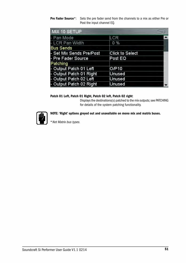
51Soundcraft Si Performer User Guide V1.1 0214
Pre Fader Source*: Sets the pre fader send from the channels to a mix as either Pre or Post the input channel EQ.
Patch 01 Left, Patch 01 Right, Patch 02 left, Patch 02 right: Displays the destinations(s) patched to the mix outputs; see PATCHING
for details of the system patching functionality.
NOTE: ‘Right’ options greyed out and unavailable on mono mix and matrix buses.
*Not Matrix bus types.

52 Soundcraft Si Performer User Guide V1.1 0214
CLEARThe CLEAR facility allows channels, buses or logical groups of channels to be reset to their factory defaults. The operation is instigated by holding the CLEAR key while pressing one of the following keys:
• HPF — Sets HPF OFF and sets Filter value to Factory Default
• Gate — Sets GATE OFF and sets Gate values to Factory Default
• Comp — Sets COMP OFF and sets Comp values to Factory Default
• EQ — Sets EQ ON and sets EQ values to Factory Default
• SELect — Sets all channel audio parameters on SELected channel to Factory Default
NOTE: Patching and naming is NOT included in resetting a channel.
• GLOBAL GAIN — On current layer sets all input gains on to factory default for selected source type, +5dB for mic sources, 0dB trim for line sources
• GLOBAL FILT — On current layer sets all HPF OFF and sets all filter values to factory default
• GLOBAL PAN — On current layer sets all PAN or BAL controls to centre
• MUTE MASTER 1—8 — Clears ALL slaves assigned to MUTE GROUP 'n'; console must be in mute set-up for this function to operate
• VCA MASTER + [MUTE MASTER 1—8] — Clears ALL slaves assigned to VCA master 'n'; console must be in VCA set-up for this function to operate
• MIX 1—14 — Sets sends from all channels to MIX 'n' to Factory Default
• MTX 1—4 — Sets sends from all buses to MTX 'n' to Factory Default
• FX 1—4 — Sets sends from all channel to FX 'n' to Factory Default
• GEQ HI or LO — Sets all GEQ bands to 0dB for SELected bus NOTE: Not all functions are present in all modes e.g. Buses have no HPF function, in these events the action has no function.
NOTE: Not all functions are present in all modes e.g. Buses have no GATE function; in these events the action has no function.

53Soundcraft Si Performer User Guide V1.1 0214
DEFAULT PATCHING AND FADER LAYERSThe fader layers on Si PERFORMER are arranged in a simple and logical form, by default the fader layers are as follows:
• A: Nominally first bank of mono channels (1-22 PERFORMER 2, 1-30 PERFORMER 3).
• B: Nominally additional mono channels plus eight stereo channels (23-36 plus stereo 1-4 and FX 1-4 Si PERFORMER 2, 31-52 plus stereo 1-4 and FX 1-4 Si PERFORMER 3).
• C: Nominally all Mix bus masters (1-14)* and VCA Masters 1-8.
• D: Nominally all Matrix bus masters (1-4)* and DMX Masters (A-D).
* Mixes 9-14 and matrix mixes 1-4 may be set to operate as mono or stereo without affecting the number of simultaneous independent mixes you can have.
The FaderGlow system indicates the type of channel, bus or function is associated with any given fader on the surface.
The patching system on Si PERFORMER is very flexible and allows almost any physical input to be patched to any logical channel; the default patches on the Si PERFORMER are as follows:
Si PERFORMER 2 FADER INPUT PATCHING & LAYERS:
• Mic In 1-22 > Channels 1-22 > Fader Layer A faders 1-22.
• Mic In 23-24 > Channels 23-24 > Fader Layer B faders 1-2.
• Unassigned inputs x12 > Channels 25-36 > Fader Layer B faders 3-14.
• Line Inputs 1-8 > Channels 37-44 > Fader Layer B faders 15-18 (nominally stereo inputs 1-4).
• Ste FX Returns 1-4 > Channels 45-52 > Fader Layer B faders 19-22 (nominally stereo inputs 5-8).
Si PERFORMER 3 FADER INPUT PATCHING & LAYERS:
• Mic In 1-30 > Channels 1-30 > Fader Layer A faders 1-30
• Mic In 31-32 > Channels 31-32 > Fader Layer B faders 1-2
• Unassigned inputs x 20 > Channels 33-52 > Fader Layer B faders 3-22
• Line Inputs 1-8 > Channels 53-60 > Fader Layer B faders 23-26 (nominally stereo inputs 1-4).
• Ste FX Returns 1-4 > Channels 61-68 > Fader Layer B faders 27-30 (nominally stereo inputs 5-8).

54 Soundcraft Si Performer User Guide V1.1 0214
Si PERFORMER OUTPUT PATCHING & LAYERS:As all Si PERFORMER models offer the same level of output processing and number of physical output all models have almost identical Output Layers & Patching systems:
• MIXES 1-14 > Fader Layer C faders 1-14 > Analogue Line Out 1-14.
• VCA 1-8> Fader Layer C faders 15-22.
• MTX 1-4 > Fader Layer D faders 1-4 > Not Assigned.
• Main L&R > Master L&R Fader > Analogue Line Out 15-16.
• MONO > MONO/SEL Fader > Not Assigned.
• DMX Masters A-D > Fader Layer D 19-22 (27-30 Performer 3).
NOTE: Any 'unused' faders and associated switches, meters and encoders are unlit and have no function.
NOTE: Patching can be set or changed from the INPUT & VCA or OUTPUT & DMX menu as appropriate.

55Soundcraft Si Performer User Guide V1.1 0214
PATCHINGThe patching system on the Si console allows almost any source to feed any channel and any bus to feed any output; the following functionality is available:
• Input Patch — Source for an input channel, selected from the INPUTS & VCA menu
• Direct Out Patch — Destination for a channel direct out, selected from the INPUTS & VCA menu
• Bus Patch (x2) — Destination for a bus out, selected from the OUTPUTS & DMX menu
• Oscillator Patch — Destination for a oscillator out, selected from the OSC menu
• Monitor Patch — Destination for a monitor line out, selected from the MONITOR menu
Once the PATCH window opens you can quickly change the patching of other channels or buses simply by SELecting an alternative input or bus.
NOTE: Patch changes are stored per cue, having made any patch changes the cue must be stored or updated to make the change permanent.
NOTE: The system will only show option cards if fitted, if the show was created on a console with an expansion card fitted or if the show was created with an option card in the offline editor Virtiual Si.
Setting or Changing the Input Patch
The INPUT PATCH screen shows the current input patch with an orange ‘tick’ (in this case MIC Input 1, to channel name Bass DI which is channel 1 on the console).To change to another source simply touch the icon or browse alternative sources using the scroll/adjustencoder or left/right (< >) arrows on the touch screen.
To have the system automatically patch multiple channels press the AUTO COMPLETE button; this will increment the input by 1 and patch by 1 until a logical group of patches is complete; see Auto Complete Boundaries for more information..
To leave the PATCH set-up press MENU, CUE LIST or FX.
NOTE: The system will display a warning requiring confirmation before the AUTO re-patch happens.NOTE: Any single input may be used a maximum of four times, in the event you attempt to use a single source more than this a warning will be displayed.

56 Soundcraft Si Performer User Guide V1.1 0214
Setting or Changing the Direct Out Patch
The DIRect OUT PATCH screen shows the current direct output patch with an orange ‘tick’ other outputs that are in use have a gray ‘tick’ whilst unused patches have no ‘tick’ (in this case from channel name Bass DI which is channel 1 on the console to analogue output 1). To change to another destination simply touch the icon or browse alternative destinations using the SCROLL/ADJUST encoder or left/right (< >) arrows on the touch screen.
Setting or Changing the Bus or Master Output Patch
The OUTPUT PATCH1(/PATCH2) screen shows the current bus output patch with an orange ‘tick’; other outputs that are in use have a gray ‘tick’ whilst unused patches have no ‘tick’ (in this case from bus name Lead Vocal which is bus 9 on the console to analogue output 9). To change to another destination simply touch the icon or browse alternative destinations using the SCROLL/ADJUST encoder or left/right (< >) arrows on the touch screen.
NOTE: The system will provide a warning if you attempt to use a patch that is already in use allowing you to either continue or abort the action.
To have the system automatically patch multiple buses press the AUTO COMPLETE button; this will increment the input by 1 and patch by 1 until a logical group of patches is complete.
To leave the PATCH set-up press MENU, CUE LIST or FX.
NOTE: The L & R buses will always patch as an odd/even pair.NOTE: There are two patch destinations for all bus outputs, the patch being made will depend upon which ‘Patch’ you selected to enter the patching pages, either Patch 01 or Patch 02.
57Soundcraft Si Performer User Guide V1.1 0214
Setting Oscillator and Monitor Patches
It is possible to change other output patches in the system from within the appropriate MENU:
• OSC: Oscillator re-patching is initiated from the OSC menu; the method is as for bus output patches however the oscillator may only be patched to one destination.
• MONITOR OUT: It is possible to assign additional line outputs for the monitor L and R from the MONITOR menu; the method is similar as for bus output patches however the monitor left and right will be patched together as a stereo pair and only one ‘paired’ destination is allowed.
Patching Replay Filtering
It is possible to isolate patching changes from the automation from the EDIT SHOW menu to prevent the automation from changing system patching when a cue is recalled. To isolate an item scroll to the desired list item, press the encoder and select Isolate.
Auto Complete Boundaries
Boundaries exist to prevent AUTO COMPLETE overwriting too many channels and mix buses or physical inputs and outputs. The boundaries are nominally grouped in eights (e.g. mic inputs 1-8, mic inputs 9-16, input channels 17-24, input channels 25-32).
However they may be smaller if the boundary group is not divisible by 8 — e.g. mix 1-8 is a logical group of 8 and could be patched to line out 1-8; but mix 9-14 is a group of 6 so the boundary for mix buses stops there.
If you start mix bus 9 patched to line out 9 then ‘AUTO COMPLETE’, the process will stop at mix bus 14 to line out 14. However if you started with mix bus 1 to line out 9 then’ AUTO COMPLETE’, the process will stop at mix bus 8 to line out 16.
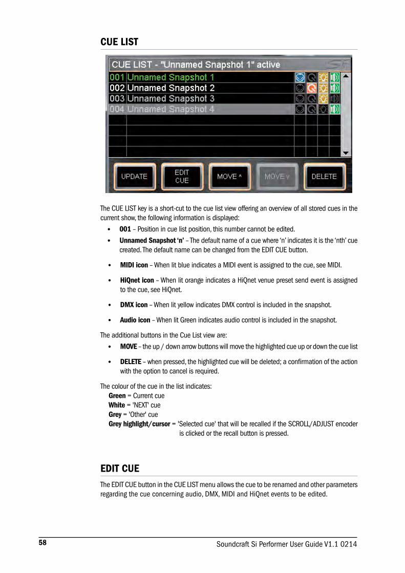
58 Soundcraft Si Performer User Guide V1.1 0214
CUE LIST
The CUE LIST key is a short-cut to the cue list view offering an overview of all stored cues in the current show, the following information is displayed:
• 001 – Position in cue list position, this number cannot be edited.
• Unnamed Snapshot ‘n’ – The default name of a cue where ‘n’ indicates it is the ‘nth’ cue created. The default name can be changed from the EDIT CUE button.
• MIDI icon – When lit blue indicates a MIDI event is assigned to the cue, see MIDI.
• HiQnet icon – When lit orange indicates a HiQnet venue preset send event is assigned to the cue, see HiQnet.
• DMX icon – When lit yellow indicates DMX control is included in the snapshot.
• Audio icon – When lit Green indicates audio control is included in the snapshot.
The additional buttons in the Cue List view are:
• MOVE – the up / down arrow buttons will move the highlighted cue up or down the cue list
• DELETE – when pressed, the highlighted cue will be deleted; a confirmation of the action with the option to cancel is required.
The colour of the cue in the list indicates: Green = Current cue White = 'NEXT' cue Grey = 'Other' cue Grey highlight/cursor = 'Selected cue' that will be recalled if the SCROLL/ADJUST encoder
is clicked or the recall button is pressed.
EDIT CUEThe EDIT CUE button in the CUE LIST menu allows the cue to be renamed and other parameters regarding the cue concerning audio, DMX, MIDI and HiQnet events to be edited.

59Soundcraft Si Performer User Guide V1.1 0214
DMX & CUE TYPEThe selected cue may be flagged by 'type' as either Audio Only, DMX Only or Audio & DMX. The flag dictates what type of automation data is played out for that cue according to the setting. This feature allows there to be multiple audio cues for a single DMX scene, multiple DMX scenes for as single audio cue or 1 cue with audio and DMX changes.
NOTE: When storing a cue all lighting and audio data is stored regardless of the Cue Type flag setting.
For the DMX component of any cue a fade time may be applied, the fade time is the time required to move from the ‘current position’ to new target position. To edit the fade time use the scroll-adjust encoder to highlight the fade time then click to access the drop-down window.
If a DMX fade is in progress and another cue is recalled the ‘fade-in-progress’ stops and a new fade is calculated based on the new target and fade time.
MIDIAs part of the cue replay function Si PERFORMER can send MIDI messages when a cue is replayed to trigger events in other systems or replay a cue in response to an incoming MIDI message.
Set-up for the MIDI function is from within the CUE LIST, scroll to the cue in which you wish the MIDI event to happen, press the EDIT CUE button then use the scroll/adjust encoder to select and edit the parameters:
NOTE: If MIDI Program Change is set On, the MIDI icon in the Cue List view will be lit blue.
NOTE: In the event two or more cues are set to receive the same program change on the same MIDI channel the console shall play the first cue in the CUE LIST that satisfies the condition.

60 Soundcraft Si Performer User Guide V1.1 0214
HiQNet™As part of the cue replay function Si PERFORMER can send HiQnet messages when a cue is replayed to trigger events in a HiQnet system. Set-up for the HiQnet function is from within the CUE LIST, scroll to the cue in which you wish the HiQnet event to happen and press the EDIT CUE button:
• Venue Recall – Set On or Off to enable or disable sending of HiQnet Venue Recall preset messages when the cue is replayed.
• Venue Number – Sets the HiQnet Venue Number that is sent; range is 1- 65535.
NOTE: If HiQnet Venue Recall is set On, the HiQnet icon in the Cue List view will be lit orange.
To learn more about the Harman HiQnet system visit http://hiqnet.harmanpro.com/
OPTION CARD SLOTSThe Si PERFORMER features two expansion slots, each compatible with all Si series option cards.
Slot 1 offers 64 in and 64 out and supports a Soundcraft /Studer connected stagebox. All 64 inputs (digital in 1-64) and outputs (digital out 1-64) are freely assignable / patchable.
Slot 2 offers 64 in and 56 out and supports a Soundcraft /Studer connected stagebox. All 64 inputs (digital in 65-128) are freely assignable, as are the first 32 outputs (digital out 65-96).
For a detailed description of the cards refer to the Si Option Card User Manual available from www.soundcraft.com

61Soundcraft Si Performer User Guide V1.1 0214
HEADPHONE OUT & MONITORINGThe Si PERFORMER features a comprehensive monitoring system. The active monitor signal is always available on the headphone output (located below the armrest near fader 1) with level controlled by the MON LEVEL encoder however the monitor signal may also be patched in parallel to other outputs on the console, see PATCHING.
The monitor output nominally follows the main L&R mix but will interact with the SOLO systems and is affected by the options available from the MONITOR page on the main menu.
The stereo MONITOR meters provide a visual indication of the overall level in the monitor system. .
NOTE: The selected monitor source is always over-ridden by any active AFL or PFL signal, the presence of such is indicated by illumination of the PFL or AFL lights and the illumination of the SOLO CLEAR key.

62 Soundcraft Si Performer User Guide V1.1 0214
SI PERMER DMX FUNCTIONALITYThe Si PERFORMER DMX control system operates in a similar manner to a 2, 3 or 4 channel preset lighting console. There are 4 DMX controller fader layers accessed by a press and hold of the [ALT] key plus A/B/C/D.
NOTE: While on a DMX layer, the fader layer keys are lit orange.
Each layer presents the 22 (Si PERFORMER 2) or 30 (Si PERFORMER 3) DMX controllers hard patched to DMX addresses 1-22 (Si PERFORMER 2) or 1-30 (Si PERFORMER 3). Each layer has a dedicated master which acts as an overall level control for the DMX channels.
Si PERFORMER DMX works on an HTP (highest value takes priority/precedence); the ‘output’ of any DMX channel/address is the highest of the four layers as shown in the examples below.
DMX channel1 MASTER A@ MASTER B@ MASTER C@ MASTER D@ Winner is…100% 0% 25% 50% 100% ‘D’ @ 100%100% 75% 50% 30% 25% ‘A’ @ 75%50% 10% 50% 40 30% ‘B’ @ 25%
To understand the maths, a fader at maximum (100%/FL) should be considered to have a value of 1 whilst a fader at minimum (0%) should be considered to have a value of 0; the fader law is linear. The resultant output of any DMX channel is DMX channel value * DMX master value so in the 3rd example the winning result was DMX MASTER B 0.5 (50%) * DMX master 0.5 (50%) = 0.25 (25%).
NOTE: DMX math differs from audio channels and VCAs where the resulting audio out is channel level * VCA1 * VCA2 * VCA3 etc… so once one VCA is at minimum (value=0) the resulting output of the channel is ‘0’ / -inf. dB.
When storing a cue on the console all audio and DMX settings; use the global ISOlate functions in the SHOW menu to prevent unwanted changes to the audio when playing a lighting cue (and vice versa).

63Soundcraft Si Performer User Guide V1.1 0214
POWER OFFThe Si PERFORMER incorporates a safety feature to prevent the power ‘accidently’ being turned off. To shut down the console:
a. Press and hold the POWER key for ~2 seconds, the power light will flash orange.
b. To confirm the shut down press the POWER key again whilst the light is flashing.
If the confirmation is not received within ~5 seconds the command is cancelled and the POWER key reverts to solid green.
SOFTWARE UPDATESThe Si PERFORMER software is updated via the USB port on the front panel. Details and special instructions for any release will be included with the software release package however the ‘normal’ procedure is listed below for reference:
a. Unzip the files to a USB key in the root directory, you should have two or three files: Performer.bin info.xml PerformerFader.hex (optional, see release notes)
b. Switch the console off using the POWER key.
c. Press and hold the POWER key for approx 5 seconds, a SOFTWARE LOADER screen shall appear.
d. Insert your USB stick and then press the MENU key.
e. Select the INFO.XML file using the adjust encoder, the LOAD button at the bottom right of the touch screen window will appear when a valid selection is made.
f. Press the LOAD button. Software will begin loading.
g. Wait until both progress bars have reached 100%, and the 'tick' symbol has appeared to the right of each progress bar, before removing the USB stick.
NOTE: Always follow on-screen instructions and release notes as updates to fader firmware or similar may require additional user input.
RESET TO FACTORY DEFAULTThe following procedure will restore the console back to the factory defaults. NOTE: All settings, cues, users, profiles and shows will be lost.
a. Starting with the console off, hold the POWER key for ~5 seconds until the console starts.
b. Press the MENU key once the loader screen appears.
c. Press the LR, MONO and FX1 keys together, this opens the update page.
d. Press the CLEAR SD CARD button on the touch screen.
e. Restart the console.

64 Soundcraft Si Performer User Guide V1.1 0214
USING YOUR Si PERFORMER CONSOLE The final output from your sound system can only ever be as good as the weakest link in the chain, and especially important is the quality of the source signal because this is the starting point of the chain. Just as you need to become familiar with the control functions of your mixer, so you must recognise the importance of correct choice of inputs, microphone placement and input channel settings. However, no amount of careful setting up can take account of the spontaneity and unpredictability of live performance. The mixer must be set up to provide “spare” control range to compensate for changing microphone position and the absorption effect of a large audience (different acoustic characteristics from soundcheck to show).
MICROPHONE PLACEMENTCareful microphone placement and the choice of a suitable type of microphone for the job is one of the essentials of successful sound reinforcement. The diagrams on the left show the different pick-up patterns for the most common types of microphone. Cardioid microphones are most sensitive to sound coming from in front, and hypercardioid microphones offer even greater directivity, with a small amount of pickup behind the microphone. These types are ideal for recording vocalists or instruments, where rejection of unwanted sounds and elimination of feedback is important. The aim should be to place the microphone as close as physically possible to the source, to cut out unwanted surrounding sounds, allow a lower gain setting on the mixer and avoid feedback. Also a well chosen and well placed microphone should not need any appreciable equalisation.There are no exact rules, let your ears be the judge. In the end, the position that gives the desired effect is the correct position!
INITIAL SETUPOnce you have connected up your system (see the sections on connection and wiring earlier in this manual for guidance) you are ready to set initial positions for the controls on your mixer. Set up individual input channel as follows:
• Connect your sources (microphone, keyboard etc.) to the required inputs. WARNING: Phantom powered mics should be connected before the +48V
is switched on. Ensure the PA system is OFF when switching phantom power on or off.
• Set Master faders at 0, input faders at 0, and set power amplifier levels to about 70%.
• Provide a typical performance level signal and press the PFL button on the first channel, monitoring the level on the bargraph meters.
• Adjust the input gain until the meter display is in the amber section, with occasional peaks to the first red LED at a typical maximum source level. This allows sufficient headroom to accommodate peaks and establishes the maximum level for normal operation (but see note below).
• Repeat this procedure on other channels as required. As more channels are added to the mix, the meters may move into the red section. Adjust the overall level using the Master Faders if necessary.
• Listen carefully for the characteristic sound of “feedback”. If you cannot achieve satisfactory input level setting without feedback, check microphone and speaker placement and repeat the exercise. If feedback persists, it may be necessary to use a Graphic Equaliser to reduce the system response at particular resonant frequencies.
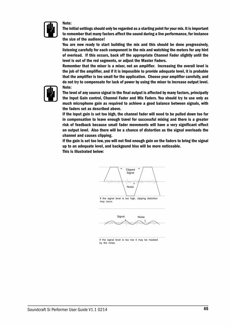
65Soundcraft Si Performer User Guide V1.1 0214
Note: The initial settings should only be regarded as a starting point for your mix. It is important to remember that many factors affect the sound during a live performance, for instance the size of the audience!You are now ready to start building the mix and this should be done progressively, listening carefully for each component in the mix and watching the meters for any hint of overload. If this occurs, back off the appropriate Channel Fader slightly until the level is out of the red segments, or adjust the Master Faders.Remember that the mixer is a mixer, not an amplifier. Increasing the overall level is the job of the amplifier, and if it is impossible to provide adequate level, it is probable that the amplifier is too small for the application. Choose your amplifier carefully, and do not try to compensate for lack of power by using the mixer to increase output level.Note: The level of any source signal in the final output is affected by many factors, principally the Input Gain control, Channel Fader and Mix Faders. You should try to use only as much microphone gain as required to achieve a good balance between signals, with the faders set as described above. If the input gain is set too high, the channel fader will need to be pulled down too far in compensation to leave enough travel for successful mixing and there is a greater risk of feedback because small fader movements will have a very significant effect on output level. Also there will be a chance of distortion as the signal overloads the channel and causes clipping. If the gain is set too low, you will not find enough gain on the faders to bring the signal up to an adequate level, and backgound hiss will be more noticeable. This is illustrated below:
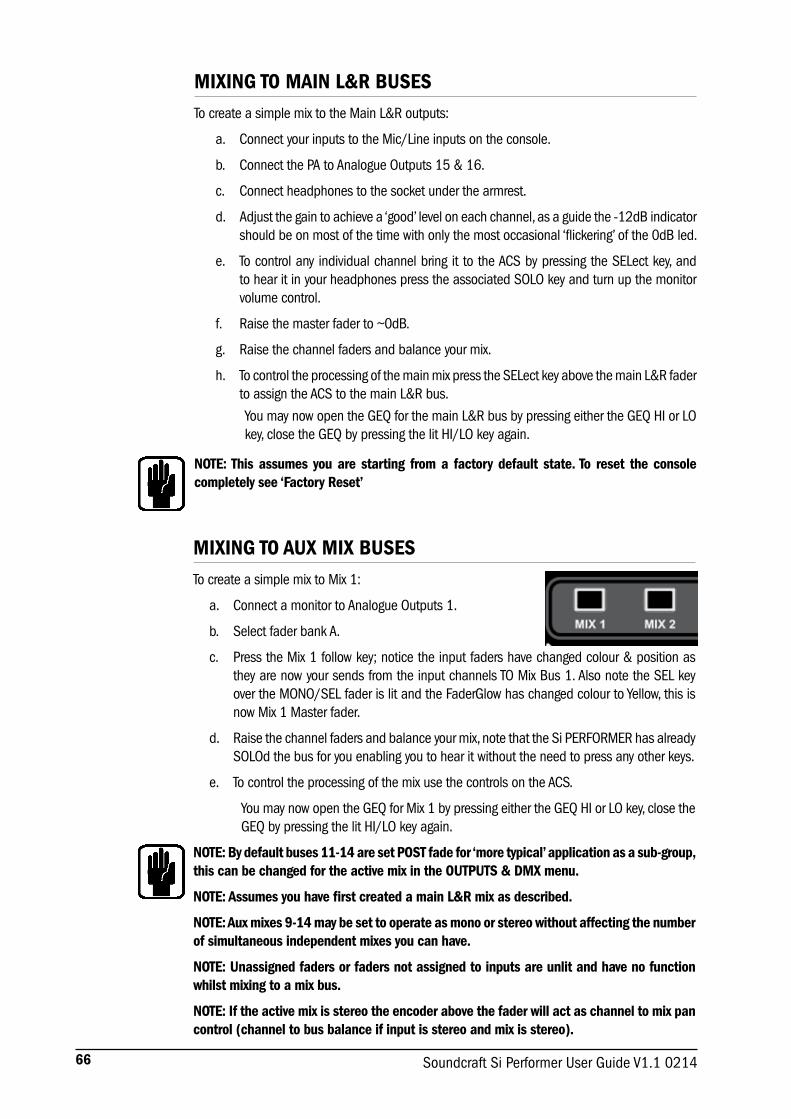
66 Soundcraft Si Performer User Guide V1.1 0214
MIXING TO MAIN L&R BUSESTo create a simple mix to the Main L&R outputs:
a. Connect your inputs to the Mic/Line inputs on the console.
b. Connect the PA to Analogue Outputs 15 & 16.
c. Connect headphones to the socket under the armrest.
d. Adjust the gain to achieve a ‘good’ level on each channel, as a guide the -12dB indicator should be on most of the time with only the most occasional ‘flickering’ of the 0dB led.
e. To control any individual channel bring it to the ACS by pressing the SELect key, and to hear it in your headphones press the associated SOLO key and turn up the monitor volume control.
f. Raise the master fader to ~0dB.
g. Raise the channel faders and balance your mix.
h. To control the processing of the main mix press the SELect key above the main L&R fader to assign the ACS to the main L&R bus.
You may now open the GEQ for the main L&R bus by pressing either the GEQ HI or LO key, close the GEQ by pressing the lit HI/LO key again.
NOTE: This assumes you are starting from a factory default state. To reset the console completely see ‘Factory Reset’
MIXING TO AUX MIX BUSESTo create a simple mix to Mix 1:
a. Connect a monitor to Analogue Outputs 1.
b. Select fader bank A.
c. Press the Mix 1 follow key; notice the input faders have changed colour & position as they are now your sends from the input channels TO Mix Bus 1. Also note the SEL key over the MONO/SEL fader is lit and the FaderGlow has changed colour to Yellow, this is now Mix 1 Master fader.
d. Raise the channel faders and balance your mix, note that the Si PERFORMER has already SOLOd the bus for you enabling you to hear it without the need to press any other keys.
e. To control the processing of the mix use the controls on the ACS.
You may now open the GEQ for Mix 1 by pressing either the GEQ HI or LO key, close the GEQ by pressing the lit HI/LO key again.
NOTE: By default buses 11-14 are set POST fade for ‘more typical’ application as a sub-group, this can be changed for the active mix in the OUTPUTS & DMX menu.
NOTE: Assumes you have first created a main L&R mix as described.
NOTE: Aux mixes 9-14 may be set to operate as mono or stereo without affecting the number of simultaneous independent mixes you can have.
NOTE: Unassigned faders or faders not assigned to inputs are unlit and have no function whilst mixing to a mix bus.
NOTE: If the active mix is stereo the encoder above the fader will act as channel to mix pan control (channel to bus balance if input is stereo and mix is stereo).

67Soundcraft Si Performer User Guide V1.1 0214
MIXING TO FX BUSESTo create a simple mix to FX Processor 1:
NOTE: This function may only be enabled if an FX processor is patched to a stereo input; this is achieved from the PATCH function in the inputs window.
a. Select fader bank A.
b. Press the FX1 follow key; notice the input faders have changed colour and position as they are now your sends from the input channels TO FX Processor 1 whilst the ON keys are now the routing ON/OFF from the channel to the FX bus. Also note the SEL key over the MONO/SEL fader is lit and the FaderGlow has changed colour to Cyan as it operates as the FX Return 1 Channel fader whilst in follow mode.
c. Raise the channel faders and balance your mix. Note that the Si PERFORMER has already SOLOd the FX Return for you, enabling you to hear it without the need to press any other keys.
d. To control the processing of the FX Return use the controls on the ACS.
e. Raise the Mono/SEL fader to bring the FX Return into the main mix.
NOTE: Assumes you have created a main L&R mix and Aux Mix as described.
NOTE: Unassigned faders or faders not assigned to inputs are unlit and have no function whilst mixing to an FX bus.
MIXING TO MATRIX BUSESTo create a simple mix to Matrix Mix 1:
a. Select fader bank C.
b. Press the MTX1 follow key, notice the faders have changed colour as they are now your sends from the buses to Matrix Bus 1 whilst the ON keys are now the routing ON/OFF from the buses to the Matrix. Also note the SEL key over the MONO/SEL fader is lit and the FaderGlow has changed colour to orange as this is now the MTX1 Master fader.
c. Raise fader#1 (Mix 1) to send Mix 1 to the Matrix; Note that the Si PERFORMER has already SOLOd Matrix 1 for you enabling you to hear it without the need to press any other keys. To add contribution from the L&R and MONO buses to a matrix mix press the MTX1 key again; the 3 faders to the left of the fader bank keys now operate as left, right and mono contributions to the matrix.
d. To control the processing of the Matrix use the controls on the ACS.
e. a) You may now open the GEQ for Matrix 1 by pressing either the GEQ HI or LO key, close the GEQ by pressing the lit HI/LO key again.
NOTE: A second press of the active MTX key allows individual contributions to be sent from left, right and mono buses to Matrix 'n' from faders, 20, 21 & 22 (Performer 2) or 28, 29, 30 (Performer 3).
NOTE: Assumes you have created a main L&R mix and Aux Mix as described.
NOTE: Unassigned faders or faders not assigned to bus mixes are unlit and have no function whilst mixing to a matrix bus.
NOTE: If the active mix is stereo the encoder above the fader will act as bus to matrix pan control (bus to matrix balance if bus is stereo and matrix is stereo).

68 Soundcraft Si Performer User Guide V1.1 0214
CREATING DMX CUES (SNAPSHOTS)DMX cues are stored along with all the current audio settings whenever you STORE or UPDATE a cue. To create a DMX cue:
a. Activate one of the 4 DMX fader layers by pressing the ALT key and fader layer A/B/C/D; the FaderGlow will change to white, the names of the DMX channels will be shown on the fader LCD displays and the DMX master for the active layer will be on the MONO/SEL fader.
b. Ensure the DMX master is at maximum, the DMX master affects all DMX channels.
c. Raise the DMX channel faders to create the scene you want, any channel can by ‘flashed’ by pressing the ON key which will light orange and set the intensity of that channel to full (100%/FL) whilst the on key is held)
NOTE: The DMX master can be ‘flashed’ to (100%/FL) by pressing the ON key above the MONO/SEL fader.
d. Store or update the cue using the STORE key or the UPDATE button in the CUE LIST view, the DMX settings will be recalled whenever the cue is replayed.
NOTE: DMX masters can be assigned to any of the normal A/B/C/D fader layers using the FADER SETUP function.
NOTE: Use the global ISOlate functions in the SHOW menu to prevent unwanted changes to the audio when playing lighting cue (and vice versa).
MANUAL DMX SCENESIt is possible to use the DMX capabilities of the console without storing cues, in this scenario up to 4 ‘scenes’ are created on each of the 4 DMX layers:
a. Create a scene on DMX fader layer A using the process described in CREATING DMX CUES (SNAPSHOTS).
b. When you are happy with scene bring the DMX master on DMX fader layer A to minimum then switch to DMX fader layer B by pressing the B fader layer key.
c. Create a scene on DMX fader layer B using the process described in CREATING DMX CUES (SNAPSHOTS).
d. Repeat steps 1, 2, 3 for DMX fader layers C and D as required.
e. Return to the normal audio fader layers by pressing the active DMX layer key or the ALT key and fader layer A/B/C/D.
f. Assign the DMX masters to faders on any of the normal A/B/C/D fader layers using the FADER SETUP function.
g. Fade each master up/down to fade between the scenes set on those layers.

69Soundcraft Si Performer User Guide V1.1 0214
QUICK HINTS AND TIPS
• Snapshots — Press the STORE key to create a snapshot, the CUE LIST key opens the list of snapshots where you can select the next cue to recall and, amongst other things, edit the cue name.
• Home Page — Pressing the MENU key will return the touch screen to the home page.
• Mute Groups — Assigned using the MUTE key combined with the 1-8 keys and SELect keys on the channels and buses.
• VCA Groups — Assigned using the VCA key combined with the 1-8 keys and SELect keys on the channels.
• Lexicon™ — Press the FX key to open the window to allow changing the FX type and using the SCROLL/ADJUST encoder and parameters with the four encoders below the screen.
• INPUTS & VCA — Amongst other functions this screen allows the name of the channel and the input patching to be changed.
• OUTPUTS & DMX — Amongst other functions this screen allows the name of the bus and the output patching to be changed.
• SOLO — Press and hold a SOLO key to have an auto-cancelling momentary solo.
• Audio Interrogate — Press and hold a function key like EQ or LR, the SELect keys will light on any channels where this function is ‘ON’, and whilst in this mode the SELect keys may be used to toggle the function.
• VCA/MUTE Interrogate — Press and hold the VCA or MUTE key and the LCD displays over each fader will indicate the masters to which that channel or bus may be a slave.
• CLR — CLR (clear) works logically with most audio keys to reset groups of parameters such as GEQ, EQ Compressors & similar, use CLR + Mix’n’ to reset contributions from all channels (or buses) to Mix’n’.
• Set Sends to Unity/Minimum — To set a bus send to unity while in follow mode press the ALT key plus the ON key. Sends that were ON will have levels set to unity, sends that were off will have levels set to minimum.
• Change Pre/Post — To change a channel bus between pre or post press the MIX button of the bus you wish to modify, open the OUTPUT & DMX menu, press the PRE/POST button on the LCD and use the SELect keys to toggle the pre-post status.
• Change EQ SHELF/BELL — To switch the HF or LF EQ bands to shelf mode turn the associated Q encoder CCW ‘past’ its widest point; rotate CW to return to bell mode.
• Copy/Paste — To copy a channel or similar press the COPY/PASTE button on the main LCD, tap any processing element icons you wish to exclude/include (press & hold the item you want if you only want to copy 1 element) now hold the PASTE button and use SELect to set the destination channels
• Change Names — From the INPUT & VCA or OUTPUT & DMX menus select the NAME and use the on-screen QWERTY keyboard to change the name. Names are stored as parts of a cue so don’t forget to update any cues you may have!
• Security — The default administrator password is: password (lower case). Only lock the console if you have the password to unlock it again!
• DMX — To access the DMX controller fader layers press and hold the [ALT] key plus A/B/C/D. Whilst on a DMX layer the fader layer keys are lit orange and the DMX master for the active layer (A-D) is assigned to the MONO/SEL fader.
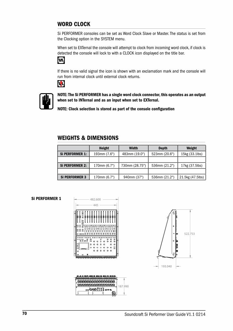
70 Soundcraft Si Performer User Guide V1.1 0214
WORD CLOCKSi PERFORMER consoles can be set as Word Clock Slave or Master. The status is set from the Clocking option in the SYSTEM menu.
When set to EXTernal the console will attempt to clock from incoming word clock, if clock is detected the console will lock to with a CLOCK icon displayed on the title bar.
If there is no valid signal the icon is shown with an exclamation mark and the console will run from internal clock until external clock returns.
NOTE: The Si PERFORMER has a single word clock connector, this operates as an output when set to INTernal and as an input when set to EXTernal.
NOTE: Clock selection is stored as part of the console configuration
WEIGHTS & DIMENSIONS
Height Width Depth Weight
Si PERFORMER 1: 193mm (7.6") 483mm (19.0") 523mm (20.6") 15kg (33.1lbs)
Si PERFORMER 2: 170mm (6.7") 730mm (28.75") 536mm (21.2") 17kg (37.5lbs)
Si PERFORMER 3 170mm (6.7") 940mm (37") 536mm (21.2") 21.5kg (47.5lbs)
482.600
445
193.040
522.753
187.990
Si PERFORMER 1

71Soundcraft Si Performer User Guide V1.1 0214
Si PERFORMER 2
Si PERFORMER 3
NOTE: Detailed DXF files are available for download from the Si Performer pages of the Soundcraft web site www.soundcraft.com

72 Soundcraft Si Performer User Guide V1.1 0214
To GEQFrom GEQ
ROUTING
HPFHighPassFilter
To GEQFrom GEQ
To GEQFrom GEQ
BLOCK DIAGRAMSAUX
MIX & MATRIX OUTPUT
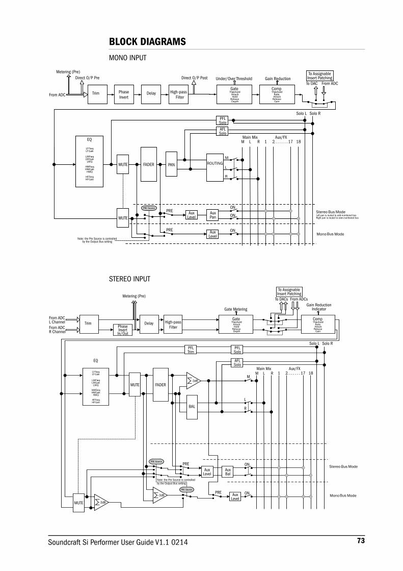
73Soundcraft Si Performer User Guide V1.1 0214
From ADC
Metering (Pre)Direct O/P Pre
Trim PhaseInvert
Delay High-passFilter
GateThreshold
AttackHold
ReleaseDepth
CompThreshold
RatioAttack
ReleaseGain
To AssignableInsert Patching
To DAC From ADCGain ReductionUnder/Over Threshold
Solo RSolo LPFLSoloAFLSolo
LM RMain Mix Aux/FX
1 2
PANFADERMUTE
EQ
LFFreqLFGain
LMFreqLMGain
LMQ
HMFreqHMGain
HMQ
HFFreqHFGain
ONMono Mode
ON
ON
AuxLevel
AuxLevel
AuxPan
PRE
PRE
MUTE
PRE Source
18. . . . . . . 17
Stereo ModeLeft pan is routed to odd-numbered busRight pan is routed to even-numbered bus
Note: the Pre Source is controlledby the Output Bus setting
Bus
Bus
ROUTINGM
L
R
Direct O/P Post
-3dB
-3dB
-3dB
PRE Source
Note: the Pre Source is controlledby the Output Bus setting
1 2 18. . . . . . . 17
Solo RSolo L
From ADCL Channel
Metering (Pre)
TrimPhaseInvertIn/Out
Delay High-passFilter
GateThreshold
AttackHold
ReleaseDepth
To AssignableInsert Patching
To DACs From ADCs
CompThreshold
RatioAttack
ReleaseGain
Gain ReductionIndicatorGate Metering
PFLSolo
AFLSolo
LM RMain Mix Aux/FX
BAL
FADERMUTE
EQ
LFFreqLFGain
LMFreqLMGain
LMQ
HMFreqHMGain
HMQ
HFFreqHFGain
M
ON
ON
AuxLevel
AuxLevel
AuxBal
PRE
PRE
MUTE
From ADCR Channel
PFLTrim
PRE Source
Mono Mode
Stereo Mode
Bus
Bus
R
L
BLOCK DIAGRAMSMONO INPUT
STEREO INPUT

74 Soundcraft Si Performer User Guide V1.1 0214
Si PERFORMER TYPICAL SPECIFICATIONS
Frequency Response Mic / Line Input to any Output +/-1.5dB, 20Hz – 20kHz
T.H.D. Mic Sensitivity -30dBu < 0.01% @ 1kHz
Noise Residual noise -86dBuMic Input E.I.N. (maximum gain) -126dBu (150Ω source) Mix noise, masters at unity < -86dBu 1 input to mix at unity gain -84dBuCMRR mic @1KHz (max gain) -80dBu
Crosstalk (@ 1kHz)Channel ON attenuation <120dBChannel Fader attenuation <120dBMic – Mic -100dB @ 1K, -85dB@10K Line – Line -100dB @ 1K, -85dB@10K
Input GainMic Gain -5dB – 58dB integrated pad design 1dB stepsLine Trim -10dB - +16dB
GateThreshold -60dBfs - -6dBfsDepth -60dB - -3dBAttack 0.1ms – 200msRelease 20ms – 500msSide-chain HPF 22Hz – 2.5KHzSide-chain LPF 160Hz – 20KHz
CompressorThreshold -52dBfs - -6dBfsRatio 1:1 – 20:1Attack 0.1ms – 200msRelease 5ms – 900msMakeup Gain 0dB – 24dB
EQAll Bands 22Hz – 20KHz, +/-15dB Q 6-0.3Shelf (HF) 800Hz – 20KHz, +/-15dB Shelf (LF) 20Hz – 500Hz, +/-15dB HPF 40Hz – 1KHz
Delay User adjustable delay 1sample – 500ms
GEQ 31Hz – 16KHz 1/3 octave

75Soundcraft Si Performer User Guide V1.1 0214
E & OE.Soundcraft reserves the right to change specifications without notice.
Digital I/OAES Sample rate converter range 8KHz – 200KHzExternal Word Clock In range 48KHz +/-7Hz (internal systems), +/-3Hz with stageboxes.Word clock out jitter +/- 7nsAnalogue out for 0dBfs +21.5dBuConverter resolution 24bitDSP resolution 40 bit floating point
LatencyMic In to Line Out <0.8 msAnalogue in to AES out <0.6 msAES in to Line Out <0.8msAES in to AES out <0.5msStagebox Mic In to Stagebox <0.9mS
Input & Output LevelsMic Input +22dBu max Line Input +22dBu max Mix Output +21.5dBu max Headphones (@150Ω) 300mW (recommended impedance 32 to 200Ω)
Input & Output ImpedancesMic Input 3kΩ Line Input 10kΩ AES Input 110ΩOutputs 150Ω (balanced), 75Ω (unbalanced)Word Clock used as Output 50ΩWord Clock used as Input 4K7ΩAES Output 110ΩDMX 120Ω
Lamp Output12v DC 100mA max (per socket)
PowerConsumption (typical) < 102W (Performer 2) 130W (Performer 3) AC Input voltage range 88-264VAC auto sensingAC Frequency range 47-63Hz
Operating ConditionsOperating Temperature Range 5°C to 45°C Humidity 0%-90%, non condensing Ta=40°C (104°F)Storage Temperature Range -20°C to 60°C (-4°F to 140°F)

76 Soundcraft Si Performer User Guide V1.1 0214
GLOSSARY
AFL After-fade listen: a function that allows the operator to monitor the post-fade signal in a channel independently of the main mix.
AUXiliary send An output from the console comprising a mix of signals from channels derived independently of the main stereo mix.
Balance The relative levels of the left and right channels of a stereo signal.
Balanced A method of audio connection which ‘balances’ the wanted signal between two wires, these wires also have a screen which carries no signal. Any interference is picked up equally by the two wires, which results in cancellation of the unwanted signal. In this guide, the term can refer to various circuit architectures. Connection details are given in relevant sections.
Clipping The onset of severe distortion in the signal path, usually caused by the peak signal voltage being limited by the circuit’s power supply voltage.
Compressor Dynamic audio process used to ‘squash’ the amplitude of the signal effectively reducing the level of this highest audio peaks
DAT Digital Audio Tape, a cassette-based digital recording format.
dB (decibel) A ratio of two voltages or signal levels, expressed by the equation dB=20Log10 (V1/V2). Adding the suffix ‘u’ denotes the ratio is relative to 0.775V RMS.
DI(direct injection)/ The practice of connecting an electric musical instrument directly to the input of the mixing console, rather than to an amplifier and loudspeaker which is covered by a microphone feeding the console.
Equaliser A device that allows the boosting or cutting of selected bands of frequencies in the signal path.
Fader A linear control providing level adjustment.
Feedback The ‘howling’ sound caused by bringing a microphone too close to a loudspeaker driven from its amplified signal.
Foldback A feed sent back to the artistes via loudspeakers or headphones to enable them to monitor the sounds they are producing.
Frequency response The variation in gain of a device with frequency.
Gain The amount of amplication in level of the signal.
Headroom The available signal range above the nominal level before clipping occurs.
Impedance balancing A technique used on unbalanced outputs to minimise the effect of hum and interference when connecting to external balanced inputs.
Insert A break point in the signal path to allow the connection of external devices, for instance signal processors or other mixers at line level signals. Nominal levels can be anywhere between 0dBu to +6dBu, usually coming from a low impedance source.
Pan (pot) Abbreviation of ‘panorama’: controls the levels sent to left and right outputs.
Peaking The point at which a signal rises to its maximum instantaneous level, before falling back down again. It can also describe an equaliser response curve affecting only a band of frequencies, (like on a graphic equaliser), “peaking” at the centre of that band.
Peak LED A visual indication of the signal peaking just before the onset of clipping, which will distort the signal.
DI Box
77Soundcraft Si Performer User Guide V1.1 0214
PFL Pre-fade listen: a function that allows the operator to monitor the pre-fade signal in a channel independently of the main mix.
Phase A term used to describe the relationship of two audio signals. In-phase signals reinforce each other, out-of-phase signals result in cancellation. Phase is a measurement of relative displacement between two waves of identical frequency.
Polarity A term used to describe the orientation of the positive and negative poles of an audio connection. Normally connections are made with positive to positive, negative to negative. If this is reversed, the result will be out-of-phase signals (see ‘phase’ above).
Post-fade The point in the signal path after a fader and therefore affected by the fader position.
Pre-fade The point in the signal path before a fader, and therefore unaffected by the fader position.
Ratio The amount by which a compressor squashes a signal when compressing expressed as a ratio. 1:1 means no compression (1db input level increase to the compressor = 1db ouput level increase from the compressor) 12:1 (12dB input level increase to the compressor = 1db ouput level increase from the compressor)
Rolloff A fall in gain at the extremes of the frequency response.
Shelving An equaliser response affecting all frequencies above or below the break frequency i.e. a highpass or lowpass derived response.
Solo An almost generic term used to describe PFL or AFL functions.
Spill Acoustic interference from other sources.
Threshold Limit above which a process will start, usually used in relation to dynamic processors such as compressors or gates to set the level at which compression will start or the gate will open
Transient A momentary rise in the signal level.
Unbalanced A method of audio connection which uses a single wire and the cable screen as the signal return. This method does not provide the noise immunity of a balanced input (see above).
+48V The phantom power supply, available at the channel mic inputs, for condenser microphones and active DI boxes.
78 Soundcraft Si Performer User Guide V1.1 0214
WARRANTY
1 Soundcraft is a trading division of Harman International Industries Ltd . End User means the person who first puts the equipment into regular operation. Dealer means the person other than Soundcraft (if any) from whom the End User purchased the Equipment,
provided such a person is authorised for this purpose by Soundcraft or its accredited Distributor. Equipment means the equipment supplied with this manual.
2 If within the period of twelve months from the date of delivery of the Equipment to the End User it shall prove defective by reason only of faulty materials and/or workmanship to such an extent that the effectiveness and/or usability thereof is materially affected the Equipment or the defective component should be returned to the Dealer or to Soundcraft and subject to the following conditions the Dealer or Soundcraft will repair or replace the defective components. Any components replaced will become the property of Soundcraft.
3 Any Equipment or component returned will be at the risk of the End User whilst in transit (both to and from the Dealer or Soundcraft) and postage must be prepaid.
4 This warranty shall only be valid if:a) the Equipment has been properly installed in accordance with instructions contained in Soundcraft’s
manual; and b) the End User has notified Soundcraft or the Dealer within 14 days of the defect appearing; andc) no persons other than authorised representatives of Soundcraft or the Dealer have effected any
replacement of parts, maintenance adjustments or repairs to the Equipment; andd) the End User has used the Equipment only for such purposes as Soundcraft recommends, with
only such operating supplies as meet Soundcraft’s specifications and otherwise in all respects in accordance with Soundcraft’s recommendations.
5 Defects arising as a result of the following are not covered by this Warranty: faulty or negligent handling, chemical or electro-chemical or electrical influences, accidental damage, Acts of God, neglect, deficiency in electrical power, air-conditioning or humidity control.
6 The benefit of this Warranty may not be assigned by the End User.
7 End Users who are consumers should note their rights under this Warranty are in addition to and do not affect any other rights to which they may be entitled against the seller of the Equipment.
PRODUCTS UNDER WARRANTY
UK customers should contact their local dealer.Customers outside the UK are requested to contact their territorial distributor who is able to offer support in the local time zone and language. Please see the distributor listings on our website (www.soundcraft.com) to locate your local distributor.
OUT-OF-WARRANTY PRODUCTS
For out-of-warranty consoles purchased in the United Kingdom, please contact the Customer Services Department (e-mail: [email protected]) at the factory in Potters Bar, Hertfordshire: Telephone +44 (0)1707 665000.For all other out-of-warranty consoles, please contact the appropriate territorial distributor.
When mailing or faxing please remember to give as much information as possible. This should include your name, address and a daytime telephone number. Should you experience any difficulty please contact Customer Services Department (e-mail: [email protected]).
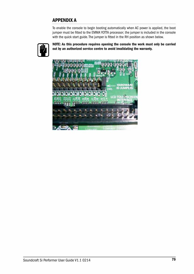
79Soundcraft Si Performer User Guide V1.1 0214
APPENDIX ATo enable the console to begin booting automatically when AC power is applied, the boot jumper must be fitted to the EMMA YOTTA processor; the jumper is included in the console with the quick start guide. The jumper is fitted in the RH position as shown below.
NOTE: As this procedure requires opening the console the work must only be carried out by an authorized service centre to avoid invalidating the warranty.

by HARMAN
®
SoundcraftHarman International Industries Ltd
Cranborne HouseCranborne Road
Potters BarHerts. EN6 3JNUnited Kingdom
+44 (0)1707 665000
www.soundcraft.com