user guide - pathwayconnect.com · user guide v 1.2 • 5/7/2018 pathway connectivity 1439 17 ave...
TRANSCRIPT

User Guide
V 1.2 • 5/7/2018
Pathway Connectivity 1439 17 Ave SE • Calgary, AB • T2G 1J9
Phone +1 (403) 243-8110 [email protected]

Copyright © Pathway Connectivity A Division of Acuity Brands Lighting Canada (“Pathway”) and its licensors.
All rights reserved.
This software and, as applicable, associated media, printed materials and “on-line” or electronic documentation (the “Software Application”) constitutes an unpublished work and contains valuable trade
secrets and proprietary information belonging to Pathway and its licensors.
iii
Contents
OVERVIEW .........................................................................................................................................1
USAGE ...............................................................................................................................................2
INSTALLATION ...................................................................................................................................2
BEFORE YOU START ................................................................................................................................2 INITIAL PROGRAM LAUNCH – IP SETTINGS....................................................................................................3
APPLICATION MAIN VIEWS.................................................................................................................4
ETHERNET DEVICE VIEW .....................................................................................................................7
SCREEN LAYOUT AND NAVIGATION .............................................................................................................7 ETHERNET DEVICE TREE ...........................................................................................................................9 CHANGING PROPERTIES ....................................................................................................................................... 9 HIDING DEVICES ............................................................................................................................................... 10 ONLINE DEVICES .............................................................................................................................................. 11 VIEWING SUBDEVICES ....................................................................................................................................... 11 FILTERING AND SEARCHING FOR DEVICES ............................................................................................................. 13 SWITCH LINK SPEED AND STATUS ........................................................................................................................ 15 DEVICE NOTES ................................................................................................................................................. 16 POE (POWER OVER ETHERNET) .......................................................................................................................... 16 POE POWER MONITORING ..................................................................................................................... 17 VLAN CONFIGURATION ......................................................................................................................... 19 VLAN PATCH ...................................................................................................................................... 20 DMX PATCH MAP ............................................................................................................................... 21 PATCH ITEMS ................................................................................................................................................... 22 DMX PATCH GRID ............................................................................................................................... 28 VIGNETTE ........................................................................................................................................... 31 VIGNETTE PLAYBACK PROPERTIES........................................................................................................................ 32 SNAPSHOTS ..................................................................................................................................................... 37 VIGNETTE ZONES .............................................................................................................................................. 39 GRANDMASTER ................................................................................................................................................ 40 RECORD ALLOWED ........................................................................................................................................... 41 EXCLUSIVE LOCK ............................................................................................................................................... 41 BLACKOUT ZONES ............................................................................................................................................. 41 GOTO INACTIVE................................................................................................................................................ 41 RELEASE ALL .................................................................................................................................................... 42 PRIORITY OVERRIDE .......................................................................................................................................... 42 VIGNETTE CLOCK .............................................................................................................................................. 42

iv
VIGNETTE VIDEOS............................................................................................................................................. 46 ETHERNET DEVICE PROPERTIES ................................................................................................................ 47 VIA SWITCH PROPERTIES ................................................................................................................................... 48 ETHERNET PORT PROPERTIES ............................................................................................................................. 51 VLAN PROPERTIES/SERVICES ............................................................................................................................. 53 PATHPORT GATEWAY PROPERTIES ...................................................................................................................... 55 DMX512 PORT PROPERTIES ON PATHPORTS........................................................................................................ 56 NSB AND VIGNETTE PROPERTIES (STATIONS AND GATEWAYS)................................................................................. 59 VIGNETTE BUTTON PROPERTIES .......................................................................................................................... 60 VIGNETTE SLIDER PROPERTIES ............................................................................................................................ 61 VIGNETTE PLAYBACK PROPERTIES........................................................................................................................ 62 TRANSACTION EDITOR ........................................................................................................................... 64 MESSAGE VIEWER ................................................................................................................................ 65 ETHERNET MAIN MENU......................................................................................................................... 67 ETHERNET FILE MENU ....................................................................................................................................... 67 VIEW MENU .................................................................................................................................................... 67 DEVICE MENU ................................................................................................................................................. 68 TOOLS MENU .................................................................................................................................................. 71 SETTINGS MENU .............................................................................................................................................. 76 WINDOW MENU .............................................................................................................................................. 76 HELP MENU .................................................................................................................................................... 78
RDM DEVICE VIEW ........................................................................................................................... 80
SCREEN LAYOUT AND NAVIGATION ........................................................................................................... 80 RDM DEVICE TREE ............................................................................................................................... 81 DEVICE TREE POP-UP MENU ITEMS ..................................................................................................................... 84 RDM DEVICE DETAILS WINDOW ............................................................................................................. 92 DETAILS .......................................................................................................................................................... 92 SUPPORTED PIDS ............................................................................................................................................. 93 DMX SETUP .................................................................................................................................................... 94 MANUFACTURER PIDS ...................................................................................................................................... 97 MESSAGE LOG ................................................................................................................................................. 98 RDM VIEW MENUS ............................................................................................................................. 99 RDM FILE MENU ............................................................................................................................................. 99 VIEW MENU .................................................................................................................................................... 99 DEVICE MENU ............................................................................................................................................... 100 SETTINGS MENU ............................................................................................................................................ 100 WINDOW MENU ............................................................................................................................................ 101
APPENDIX 1: VIA ETHERNET SWITCH DEFAULT SETTINGS................................................................ 102
APPENDIX 2: VIRTUAL LOCAL AREA NETWORK (VLAN) ................................................................... 103
DEFINITIONS ..................................................................................................................................... 103 VLAN GUIDELINES ............................................................................................................................. 103

v
APPENDIX 3: PLANNING CHARTS ................................................................................................... 105
APPENDIX 4: EAPS & RSTP – “RING PROTECTION” ........................................................................... 107
REQUIREMENTS AND LIMITATIONS ......................................................................................................... 107 DEFINITIONS FOR EAPS ....................................................................................................................... 107

vi
Figures
Figure 1 - Main Screen 5 Figure 2 - Main Tool Bar (Ethernet Device View) 7 Figure 3 - Devices Tab 9 Figure 4 - Online/Offline Icons 11 Figure 5 - DMX Ports Subdevices 12 Figure 6 - Ethernet Port Subdevices 12 Figure 7 - Button and Slider Subdevices 12 Figure 8 - Filtering Devices 13 Figure 9 - Searching Devices 14 Figure 10 - Table View 14 Figure 11 - Notes Property 16 Figure 12 - Power Tab 17 Figure 13 - VLAN Configuration Tab 19 Figure 14 - VLAN Properties 19 Figure 15 - VLAN Patch Tab 20 Figure 16 - Patch Map Tab 21 Figure 17 - Patch Items Toolbar 23 Figure 18 - DMX Patch Toolbar 25 Figure 19 - Port Group with multiple outputs 26 Figure 20 - Align Items View 26 Figure 21 - Patch Grid Tab 28 Figure 22 - Patching a universe to a port 29 Figure 23 - Patching multiple universes at same priority 29 Figure 24 - Universes automatically merged 29 Figure 25 - Patching multiple universes at different priorities 30 Figure 26 - Priority automatically created 30 Figure 27 - Vignette Gateway Playbacks 31 Figure 28 - Vignette PoE Wall station Playback 31 Figure 29 - Vignette Clock Playback 31 Figure 30 - Management of Vignette Playbacks 37 Figure 31 - Snapshot Management 38 Figure 32 - Vignette Zone Definition 39 Figure 33 - Vignette Zone Editing 40 Figure 34 - Properties Pane 47 Figure 35 - Transaction Editor 47 Figure 36 - Transaction Editor 64 Figure 37 - Message Viewer 65 Figure 38 - Dark Grey UI 68 Figure 39 - Reboot Device 69 Figure 40 - Factory Defaults 70 Figure 41 - Update Firmware 70 Figure 42 - Data Scope in Graph View 71 Figure 43 - Data Scope in DMX Monitor view 72 Figure 44 - Data Scope in White Grid view 73 Figure 45 - Data Scope in RGB Grid view 74

vii
Figure 46 - Virtual Console 75 Figure 47 - Network Interfaces 76 Figure 48 - Send System Logs 79 Figure 49 - Main Tool Bar (RDM Device View) 80 Figure 50 - Main Screen (RDM Device View) 81 Figure 51 - RDM Device Tree 82 Figure 52 - RDM Discover 84 Figure 53 - Show Identified Devices 85 Figure 54 - Devices in Identified Mode 86 Figure 55 - Device Information 86 Figure 56 - Device Details 88 Figure 57 - DMX Information 89 Figure 58 - Sensor Readings 90 Figure 59 - Device Details 92 Figure 60 - Supported PIDs 94 Figure 61 - DMX Information 95 Figure 62 - DMX Information - Multiple Devices 96

viii
Tables
Table 1 – Switch port icon colors and related statuses ..................................................................................... 15 Table 2 – PoE Status Color codes ..................................................................................................................... 17 Table 3 - PoE Status ........................................................................................................................................ 18 Table 4 - Patch Map Items .............................................................................................................................. 22 Table 5 – Vignette Snapshot Button Colors ...................................................................................................... 38 Table 6 - Switch Properties ............................................................................................................................. 48 Table 7 - Ethernet Port Properties ................................................................................................................... 51 Table 8 - VLAN Properties/Services ................................................................................................................. 53 Table 9 - Gateway Properties .......................................................................................................................... 55 Table 10 - Output DMX512 Port Properties ..................................................................................................... 56 Table 11 - Input DMX512 Port Properties ........................................................................................................ 58 Table 12 – Gateway & PoE Master Properties .................................................................................................. 59 Table 13 – Vignette Button Properties ............................................................................................................ 60 Table 14 – Vignette Slider Properties .............................................................................................................. 61 Table 15 – Vignette Button Properties ............................................................................................................ 62 Table 16 - RDM Device Icons and Descriptions ................................................................................................. 83 Table 17 - VIA Default Settings ...................................................................................................................... 102 Table 18 - VLAN Planning .............................................................................................................................. 105
1
Overview
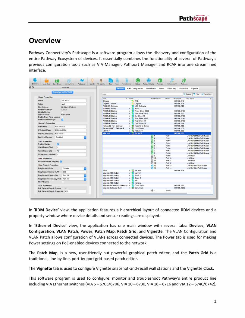
Pathway Connectivity’s Pathscape is a software program allows the discovery and configuration of the
entire Pathway Ecosystem of devices. It essentially combines the functionality of several of Pathway’s
previous configuration tools such as VIA Manager, Pathport Manager and RCAP into one streamlined
interface.
In ‘RDM Device’ view, the application features a hierarchical layout of connected RDM devices and a
property window where device details and sensor readings are displayed.
In ‘Ethernet Device’ view, the application has one main window with several tabs: Devices, VLAN
Configuration, VLAN Patch, Power, Patch Map, Patch Grid, and Vignette. The VLAN Configuration and
VLAN Patch allows configuration of VLANs across connected devices. The Power tab is used for making
Power settings on PoE-enabled devices connected to the network.
The Patch Map, is a new, user-friendly but powerful graphical patch editor, and the Patch Grid is a
traditional, line-by-line, port-by-port grid-based patch editor.
The Vignette tab is used to configure Vignette snapshot-and-recall wall stations and the Vignette Clock.
This software program is used to configure, monitor and troubleshoot Pathway’s entire product line
including VIA Ethernet switches (VIA 5 – 6705/6706, VIA 10 – 6730, VIA 16 – 6716 and VIA 12 – 6740/6742),

2
control products (Cognito2, Choreo, NSB, Vignette), Pathport gateways (Octo, Quattro, 2-Port/C-series,
Uno, Touring Edition), and eDIN interface cards (1002, 1003, 1004, 1006, 1008, 1009, 1016) as well as
eDIN gateways (1011, 1012, 1014, 1029)
Pathscape will retrieve and set operational properties for VIA Ethernet switches at the switch-wide, port-
specific and independent VLAN level. Pathscape may also be used to apply firmware changes to VIA
switches, Pathway RDM devices and Pathway controller products (Cognito2, Choreo, NSB, and Vignette).
The exact set of properties available for display is dependent on the operating firmware of each device. It
is strongly recommended to ensure the latest firmware release is used.
Usage
Pathscape has been designed for use by a knowledgeable, but infrequent user. Most architectural and
many entertainment networks are rarely reconfigured after initial commissioning. Pathscape shows
information in a graphical manner where appropriate, and attempts to prevent, or at least warn, the user
prior to committing any changes that might break communication across the network. Changes are only
made on explicit user actions. The last action may also be easily undone.
If communication with a device is lost due to misconfiguration, those with front panel user interfaces may
be factory-defaulted to restore communication.
Installation
Download and run the installer for either Windows or Mac OS. In some cases, it may be necessary to
manually establish firewall exception permissions for Pathscape to operate properly. Temporarily
disabling the firewall may be appropriate in some cases.
To launch the program, simply click the short cut icon or select Pathscape from Applications.
Before You Start
Plan your network layout, settings and numbering before making any changes to the hardware. We
strongly recommend reviewing the worksheets in Appendix 3 of this manual.
Ethernet networks require configuration of both switch-wide and port-specific functions. Further
configuration can be applied to the individual Virtual Local Area Networks if VLANs are employed. VLANs
form an abstract layer that cross the physical hardware but may have independent logic and properties.
During configuration, pay careful attention to the order in which configuration changes are sent. Straying
from a specific order may break communication with portions of your network. For example, if your
configuration PC is connected to a port on VLAN1 and the management of the switch is also on that VLAN,
you would not want to change the port’s VLAN from your PC as you would lose communication with the
Via’s management processor. Also, be careful not to plug your PC into a “Tagged” on a Via as configuring

3
the NIC on your PC to accept tagged traffic is non-trivial. If either of these events occur, you may need to
use the front panel menu to change the port back to VLAN 1, re-plug your PC into a port that you know is
on VLAN1 or reset the switch to the ‘Factory Default’ and re-discover it on your PC.
Initial Program Launch – IP Settings
Prior to starting Pathscape, the IP settings of the computer must be set by the user to settings compatible
Pathway gear as it leaves the factory. Mismatched IP settings may prevent discovery of connected devices
and will prevent you from fully configuring devices. Typically, a static IP address of 10.0.0.x, subnet mask
of 255.0.0.0, and a default gateway of 10.0.0.1 will connect to new gear using factory default settings.
Using DHCP to allocate a pool of venue-specific IP addresses using a Via switch or another device acting
as the DHCP server is possible with further configuration. (Via’s DHCP Services are configured per VLAN
and VLANs must be enabled.)
Use the “Network Interfaces” button on the top menu to review the network interface cards
Pathscape has detected.
Choose the NIC your network is connected to. It is preferable to use only one wired NIC, but using multiple
and even WiFi NICs will work. Pathscape will need to be restarted if changes to NIC’s IP settings are made
by using your computer’s Network Settings after the program has launched, but selecting NICs in the
above dialog will take effect immediately.
If your network is configured correctly, devices should appear on-line and have a green dot on their icon.
If the device is in a loaded show file, but is not yet on-line, it will have a yellow dot on its icon. Devices
with red dots mean the device was communicating with Pathscape, but has gone off-line.
4
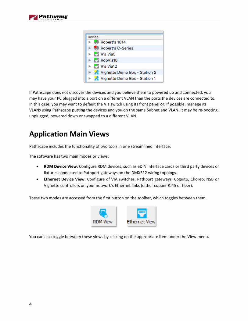
If Pathscape does not discover the devices and you believe them to powered up and connected, you
may have your PC plugged into a port on a different VLAN than the ports the devices are connected to.
In this case, you may want to default the Via switch using its front panel or, if possible, manage its
VLANs using Pathscape putting the devices and you on the same Subnet and VLAN. It may be re-booting,
unplugged, powered down or swapped to a different VLAN.
Application Main Views
Pathscape includes the functionality of two tools in one streamlined interface.
The software has two main modes or views:
• RDM Device View: Configure RDM devices, such as eDIN interface cards or third party devices or
fixtures connected to Pathport gateways on the DMX512 wiring topology.
• Ethernet Device View: Configure of VIA switches, Pathport gateways, Cognito, Choreo, NSB or
Vignette controllers on your network’s Ethernet links (either copper RJ45 or fiber).
These two modes are accessed from the first button on the toolbar, which toggles between them.
You can also toggle between these views by clicking on the appropriate item under the View menu.
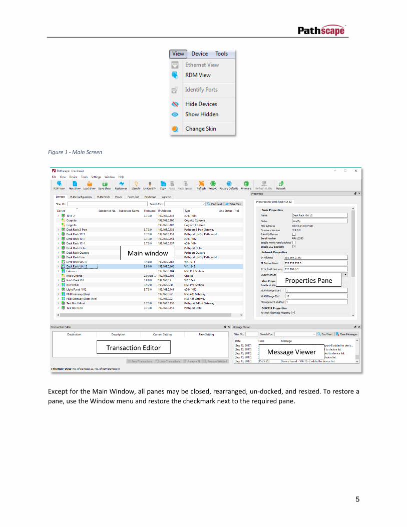
5
Figure 1 - Main Screen
Except for the Main Window, all panes may be closed, rearranged, un-docked, and resized. To restore a
pane, use the Window menu and restore the checkmark next to the required pane.
Main window
Properties Pane
Message Viewer Transaction Editor

6
The dock-able panes may also be dropped on top of each other, creating a tabbed view of the stacked
windows.
To un-dock from the main pane or from a tabbed ‘stacked’ window, press the float button on MacOS
and on Windows.

7
Ethernet Device View
Screen Layout and Navigation
Figure 2 - Main Tool Bar (Ethernet Device View)
This is a moveable/floatable toolbar which can be docked on any side of the main window. Hover the
mouse over the grab bar located on the far left or top of the tool bar and click
and drag it to the desired location. Move it outside of the main window and it becomes a floatable toolbar.
The Ethernet Device view is the default view when Pathscape starts. Pathscape displays information about
the connected devices and the network configuration through one main window. The window is
comprised of several tabs.
There are also three ancillary panes: Properties; Message Viewer; and Transaction Monitor which you
can show or hide from the Window Menu.
The “Devices” tab provides information about connected devices and when a device is highlighted it
shows the appropriate properties in the Properties pane.
The “VLAN Configuration” tab provides information on the association between port, VLANs and VLAN
types (tagged/untagged), and opens the appropriate Properties pane for the configuration of individual
ports and VLAN parameters.
The “VLAN Patch” tab offers an editable grid layout of VLAN/port associations and VLAN types.
8
The “Power” tab provides information about Pathway PoE-enabled switches on the network, and allows
the configuration of ports, including enabling/disabling PoE itself and setting maximum power allocations.
The “Patch Map” tab provides an intuitive, graphical flow-chart based patch window, allowing easy
configuration of Universes, input & output ports, and more. Patching is as simple as drawing a line to
connect two objects.
The “Patch Grid” provides a familiar grid-type patch window for quickly configuring systems, especially
when patching whole universes.
The “Vignette” tab offers configuration for Vignette Architectural Snapshot Record, Recall and Zone
control systems.
9
Ethernet Device Tree
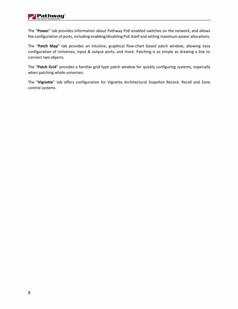
Figure 3 - Devices Tab
This tab shows all devices discovered on your network or configured in the show file. Double click on the
device or on the drop-down arrow to review individual subdevices. Columns may be rearranged by
dragging and dropping them and sorted by clicking on them. An arrow shows ascending or descending
sort order.
Changing Properties
New devices or devices that have been Factory Reset use the IP address of the device as a label, but should
be changed to something more meaningful, like ‘Stage Left Outputs’. Select the device and edit the NAME
in the Properties Pane and Send Transactions. Within a second or two, the text in the Devices tab will be
updated.
10
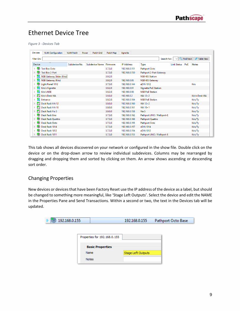
Hiding Devices
You may want to hide some devices that are not relevant to your current tasks. For example, if you
network spans multiple rooms where there are switches and gateways in a room you’re currently not
working in, you may want to hide those devices. Right Click (or Option Click) on a device and select Hide.
The number of discovered but hidden devices is shown in the status bar next to “No. of Hidden Devices”.
To unhide all devices, select ‘Show Hidden’ from the View Menu.
11
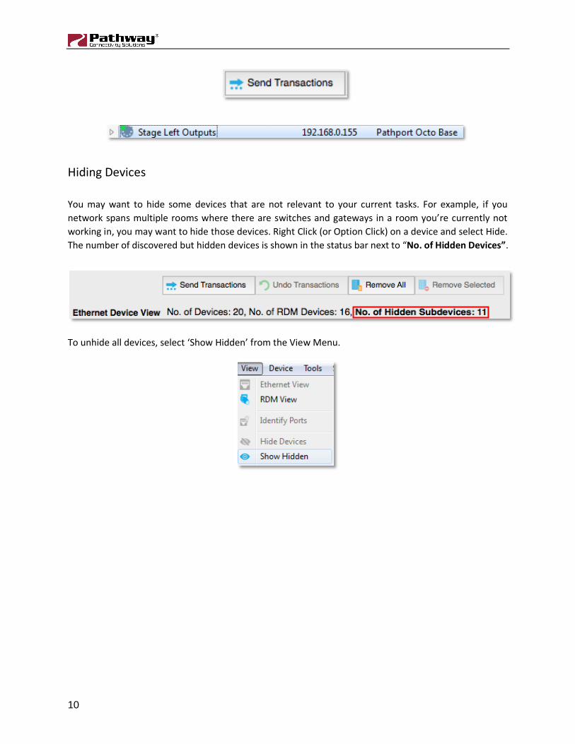
Online Devices
Devices that appear with a green icon indicates that it is currently online and you can edit its properties.
A red icon indicates communication with the device has been interrupted for some reason.
Figure 4 - Online/Offline Icons
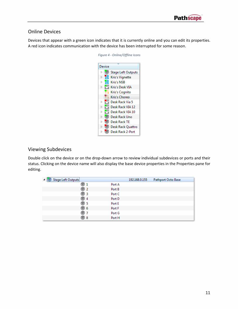
Viewing Subdevices
Double click on the device or on the drop-down arrow to review individual subdevices or ports and their
status. Clicking on the device name will also display the base device properties in the Properties pane for
editing.

12
Some devices, such as switches and gateways, have Subdevices called Ports. NSB and Vignette have button
and slider Subdevices. Vignette devices also have Playbacks. Ports on Pathports and Vias can have a
Subdevice Name.
Figure 5 - DMX Ports Subdevices
Figure 6 - Ethernet Port Subdevices
Figure 7 - Button and Slider Subdevices
13
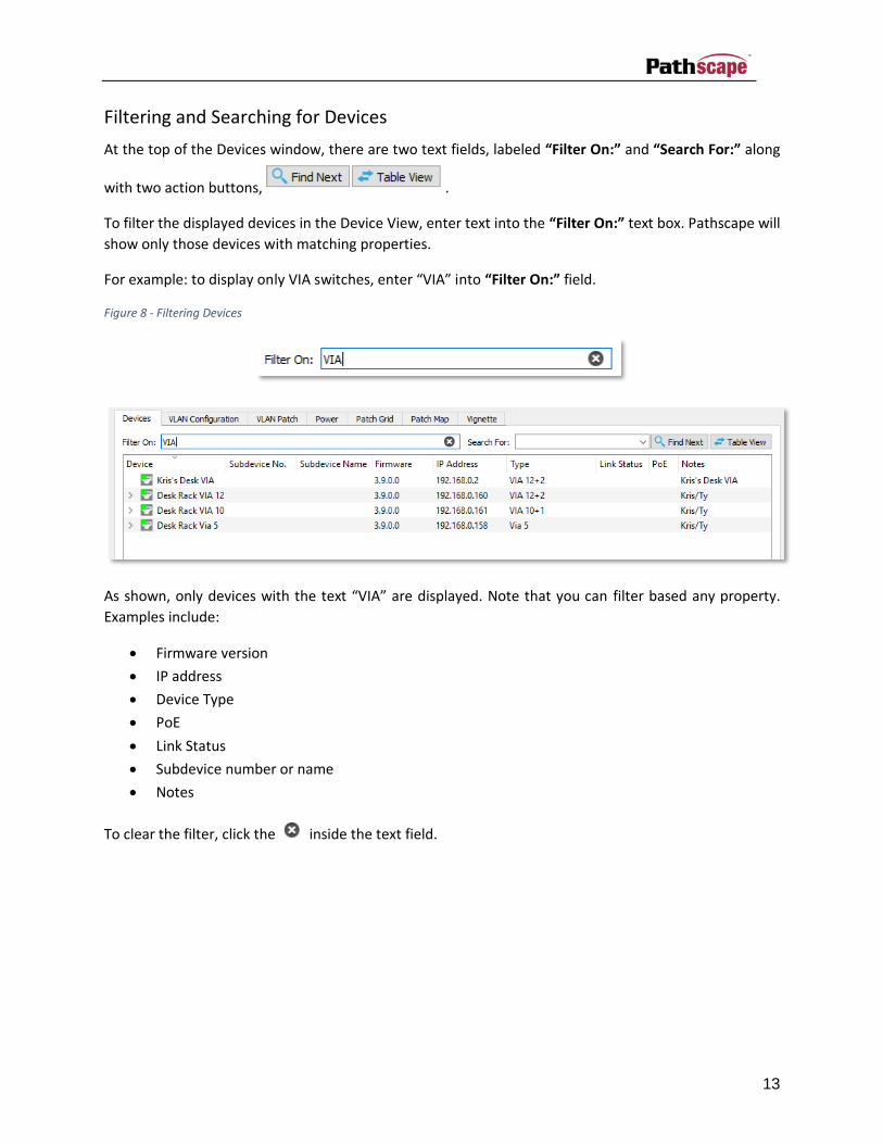
Filtering and Searching for Devices
At the top of the Devices window, there are two text fields, labeled “Filter On:” and “Search For:” along
with two action buttons, .
To filter the displayed devices in the Device View, enter text into the “Filter On:” text box. Pathscape will
show only those devices with matching properties.
For example: to display only VIA switches, enter “VIA” into “Filter On:” field.
Figure 8 - Filtering Devices
As shown, only devices with the text “VIA” are displayed. Note that you can filter based any property.
Examples include:
• Firmware version
• IP address
• Device Type
• PoE
• Link Status
• Subdevice number or name
• Notes
To clear the filter, click the inside the text field.

14
The “Search For:” field works in a slightly different way. Enter some text to search for in the text box and
press the button. Pathscape will highlight the first device that matches this search term.
Press the button again and Pathscape will highlight the next device that matches.
Figure 9 - Searching Devices
Like the Filter function, you can search for text from any of the device columns.
The button simply toggles between Table and Tree View. Tree View is the default view.
Table view shows every subdevice or port, line by line. Press to return to Tree View.
Figure 10 - Table View

15
Switch Link Speed and Status
For switch ports, link speed and status is also indicated by the color of the port icon:
Table 1 – Switch port icon colors and related statuses
Icon Color Status
Grey Link down (no downstream device connected)
Blue 1 Gigabit
Green 100 Megabit full or half duplex
Orange 10 Megabit full or half duplex

16
Device Notes
The Notes column shows any particulars for a device or subdevice recorded by the user in the Properties
pane.
Figure 11 - Notes Property
PoE (Power over Ethernet)
The PoE columns of the Devices tab displays the PoE status for each Via Ethernet port. If PoE is enabled
on a port, this column will display the PoE class, as well as the maximum PoE setting, and the current
active draw. If PoE is not available on the port, this column item remains blank.
17
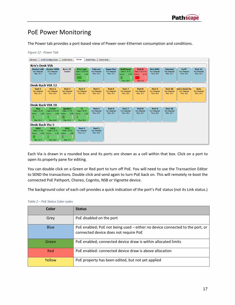
PoE Power Monitoring
The Power tab provides a port-based view of Power-over-Ethernet consumption and conditions.
Figure 12 - Power Tab
Each Via is drawn in a rounded box and its ports are shown as a cell within that box. Click on a port to
open its property pane for editing.
You can double click on a Green or Red port to turn off PoE. You will need to use the Transaction Editor
to SEND the transactions. Double click and send again to turn PoE back on. This will remotely re-boot the
connected PoE Pathport, Choreo, Cognito, NSB or Vignette device.
The background color of each cell provides a quick indication of the port’s PoE status (not its Link status.)
Table 2 – PoE Status Color codes
Color Status
Grey PoE disabled on the port
Blue PoE enabled; PoE not being used – either no device connected to the port, or connected device does not require PoE
Green PoE enabled; connected device draw is within allocated limits
Red PoE enabled: connected device draw is above allocation
Yellow PoE property has been edited, but not yet applied
18
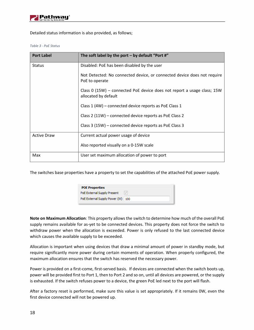
Detailed status information is also provided, as follows;
Table 3 - PoE Status
Port Label The soft label by the port – by default “Port #”
Status Disabled: PoE has been disabled by the user
Not Detected: No connected device, or connected device does not require PoE to operate
Class 0 (15W) – connected PoE device does not report a usage class; 15W allocated by default
Class 1 (4W) – connected device reports as PoE Class 1
Class 2 (11W) – connected device reports as PoE Class 2
Class 3 (15W) – connected device reports as PoE Class 3
Active Draw Current actual power usage of device
Also reported visually on a 0-15W scale
Max User set maximum allocation of power to port
The switches base properties have a property to set the capabilities of the attached PoE power supply.
Note on Maximum Allocation: This property allows the switch to determine how much of the overall PoE
supply remains available for as-yet to be connected devices. This property does not force the switch to
withdraw power when the allocation is exceeded. Power is only refused to the last connected device
which causes the available supply to be exceeded.
Allocation is important when using devices that draw a minimal amount of power in standby mode, but
require significantly more power during certain moments of operation. When properly configured, the
maximum allocation ensures that the switch has reserved the necessary power.
Power is provided on a first-come, first-served basis. If devices are connected when the switch boots up,
power will be provided first to Port 1, then to Port 2 and so on, until all devices are powered, or the supply
is exhausted. If the switch refuses power to a device, the green PoE led next to the port will flash.
After a factory reset is performed, make sure this value is set appropriately. If it remains 0W, even the
first device connected will not be powered up.

19
VLAN Configuration
A VLAN (Virtual Local Area Network) is a group of ports on the switch (or switches) that are configured to
pass traffic to one another, but not to ports on any other VLAN. When VLANs are established, ports that
connect switches to switches must be tagged to pass all VLAN traffic. See Appendix 2 for further details
on how to use VLANs.
Figure 13 - VLAN Configuration Tab
To populate or refresh this pane, click on the “Refresh VLAN Properties” button.
A drop-down arrow indicates that ports have been assigned to a particular VLAN. Clicking on the arrow or
double-clicking the VLAN ID# and selecting a switch selects the properties of the VLAN for editing. For
each VLAN you can run a DHCP Server or an IGMP Querier.
Figure 14 - VLAN Properties

20
Do not connect gateways, controllers or network sliders and buttons to tagged ports.
Tagged ports carry data for all VLANs and should only be used when connecting switches to other
switches, not for end devices. For example, if your network has two switches and two VLANs, connect
those two switches with Tagged ports and all the other ports on the switches may be members of one
VLAN or the other.
VLAN Patch
Figure 15 - VLAN Patch Tab
To populate or refresh this pane, click on the “Refresh VLAN Properties” button.
The VLAN Patch shows the available VLAN pool and port assignments using a grid layout. Changes may be
made by double-clicking in a cell and then committing the transaction.
Tagged ports transmit all VLAN data so in each VLAN column for that port there is a lighter green
checkmark.
21
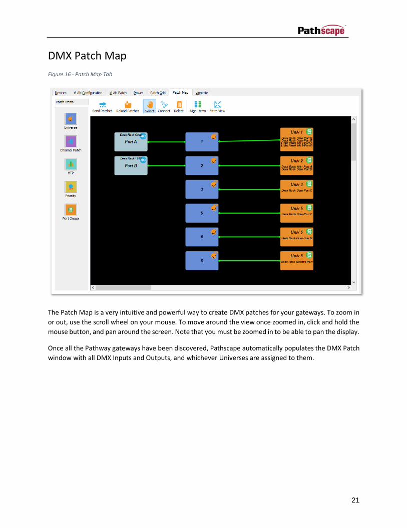
DMX Patch Map
Figure 16 - Patch Map Tab
The Patch Map is a very intuitive and powerful way to create DMX patches for your gateways. To zoom in
or out, use the scroll wheel on your mouse. To move around the view once zoomed in, click and hold the
mouse button, and pan around the screen. Note that you must be zoomed in to be able to pan the display.
Once all the Pathway gateways have been discovered, Pathscape automatically populates the DMX Patch
window with all DMX Inputs and Outputs, and whichever Universes are assigned to them.

22
Patch Items
Table 4 - Patch Map Items
Input Port
Will appear for every port on a device configured as an Input.
Output Port
Will appear for every port on a device configured as an Output.
Port Group
By default, output ports on the same universe are grouped together to keep the Patch Map window organized. Additional Port Group items may be created and Output ports may be drag-and-dropped to create custom Port Groups.
Universe
Pathscape will create a Universe item for every Universe currently patched to any port on any device on the network. Additional Universes may be created as needed to represent network sources of xDMX.
Channel Patch.
Used to create custom channel patching where the full 512 slots are not needed or slots are not contiguous or not in numerical order.
HTP (Highest Takes Precedence)
For merging multiple universes. The slot with the highest value ‘wins’.
Priority
For merging multiple universes, each input may be set from Low priority (8) to High Priority (1). Highest priority will ‘win’ when that source is present. If a

23
high priority source is not present, the next highest active source wins.
Patch items are connected via arrows. To remove all connections from a Patch item, right-click on it and
select ‘Remove Connections’. To connect two Patch items, such as a Universe to a Port, select the
‘Connect’ tool from the DMX Patch window toolbar, and draw the arrow from the first object to the
second.
Along the left of the panel, there are five Patch window items: Universe, Channel Patch, HTP, Priority and
Port Group. Using these items, custom patch can quickly be made.
Figure 17 - Patch Items Toolbar
Items may be overlapped, and can be forced behind or in front of other objects. With the target object
selected, right-click and choose either ‘Send to Back’ or ‘Bring to Front’. Drawing order does not affect the
patch logic.
24
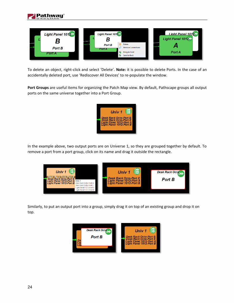
To delete an object, right-click and select ‘Delete’. Note: it is possible to delete Ports. In the case of an
accidentally deleted port, use ‘Rediscover All Devices’ to re-populate the window.
Port Groups are useful items for organizing the Patch Map view. By default, Pathscape groups all output
ports on the same universe together into a Port Group.
In the example above, two output ports are on Universe 1, so they are grouped together by default. To
remove a port from a port group, click on its name and drag it outside the rectangle.
Similarly, to put an output port into a group, simply drag it on top of an existing group and drop it on
top.

25
Figure 18 - DMX Patch Toolbar
There are several buttons on the DMX Patch window toolbar. The first, Send Patches, will send the
currently configured DMX Patch to the gateways in your network. The Reload Patches button will reload
the currently saved patches. Any unsaved changes will be lost.
26
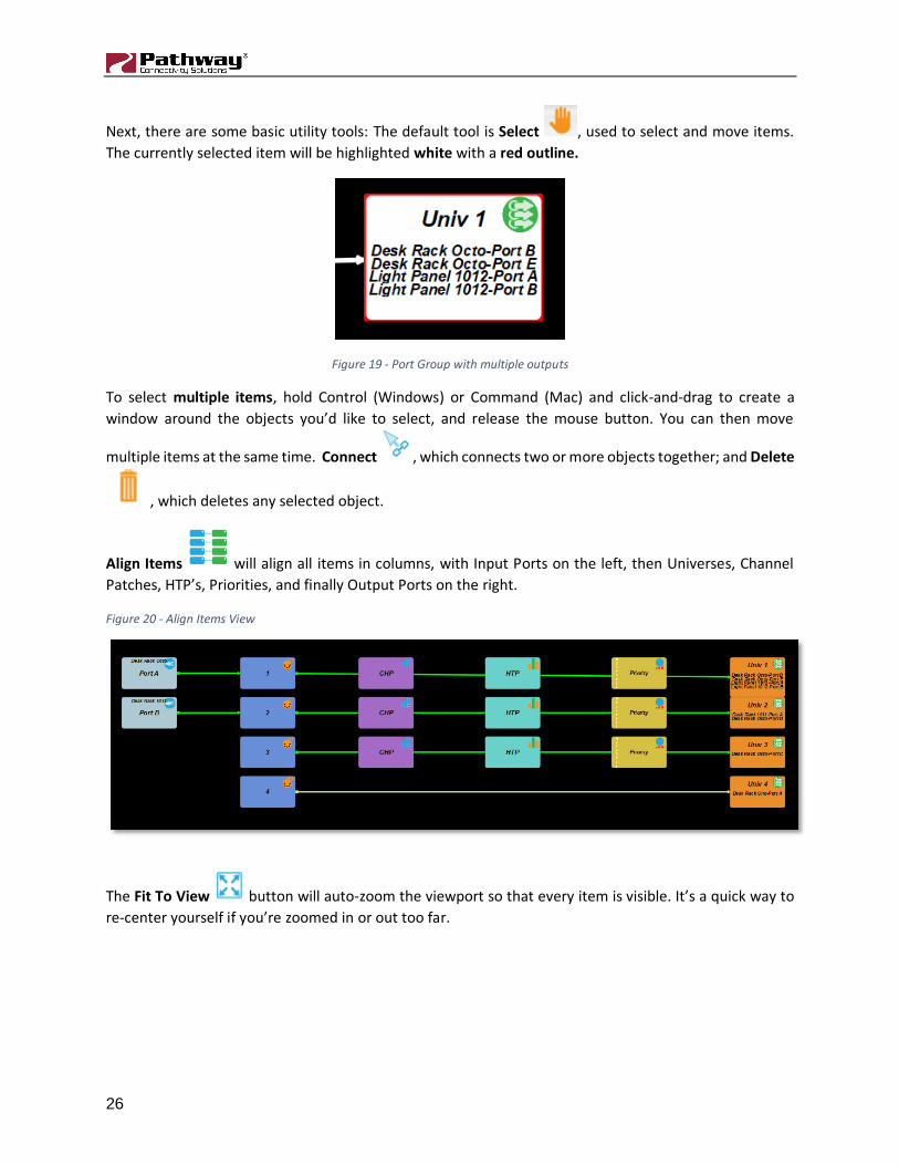
Next, there are some basic utility tools: The default tool is Select , used to select and move items.
The currently selected item will be highlighted white with a red outline.
Figure 19 - Port Group with multiple outputs
To select multiple items, hold Control (Windows) or Command (Mac) and click-and-drag to create a
window around the objects you’d like to select, and release the mouse button. You can then move
multiple items at the same time. Connect , which connects two or more objects together; and Delete
, which deletes any selected object.
Align Items will align all items in columns, with Input Ports on the left, then Universes, Channel
Patches, HTP’s, Priorities, and finally Output Ports on the right.
Figure 20 - Align Items View
The Fit To View button will auto-zoom the viewport so that every item is visible. It’s a quick way to
re-center yourself if you’re zoomed in or out too far.

27
Right-click menu options
There are a few options available when right-clicking any empty space in the Patch Map view.
Align Items and Fit to View work as described above.
Zoom All zooms out to a greater extent than Fit To View, and shows the entire Patch Map work
area.
Show/Hide Grid will toggle on & off a dotted grid for easy visual positioning of patch items.
Snap On/Off will toggle on & off item snapping. This is independent of Show/Hide grid.

28
DMX Patch Grid
Figure 21 - Patch Grid Tab
The Patch Grid window is a more traditional way to create patches. Devices and their ports are shown on
the left, along with their port group (if any) and port direction. DMX can be enabled or disabled from this
view, and the Device and Port names may be edited.
To edit a device or port name, simply double-click on it and type into the box, and press enter. You will
see a new transaction will be created in the Transaction editor, showing the current and new name. If you
move off the cell, you will see it is yellow until you send the transactions.
To the right are columns indicating universes, from 1 to 256. For patching above universe 256, add a new
Universe in the Patch Map and right-click on it and Renumber the Universe. To patch a port to a universe,
double-click in the corresponding grid cell and select the priority.

29
Figure 22 - Patching a universe to a port
Once your selection is made the row will turn blue reminding you to click the Send Patch button in
the corresponding row to send the patch to the gateway’s port.
If the same port is patched to multiple universes at the same priority, those universes will be
automatically merged (HTP). After sending the patch, check the Patch Map by clicking the Reload
Patches button.
Figure 23 - Patching multiple universes at same priority
Figure 24 - Universes automatically merged

30
If patching multiple universes at different priorities, select the appropriate priority for each in the drop-
down menu while patching. After the patch is sent, verify by clicking Reload Patches again under the
Patch Map view. Note that the universe will be pointing to the appropriate priority number along the
left side of the Priority item in the Patch Map view.
Figure 25 - Patching multiple universes at different priorities
Figure 26 - Priority automatically created

31
Vignette
Each Vignette network of architectural controls needs at least one Playback processor. Vignette 485
Architectural Gateways have four, Vignette Clocks have one and each PoE wall station has one. Vignette
485 wall stations do not have a Playback. You must uniquely identify the Playbacks (see Vignette Playback
ID below) as each Button and Slider you configure to Playback Snapshots or Zones will reference its
Playback.
In the Device tab, expand the Vignette device by double clicking on it or clicking the expand arrow to show
all its sub devices. The Playback are highlighted below:
Figure 27 - Vignette Gateway Playbacks
On a Vignette PoE wall station you will find one Playback:
Figure 28 - Vignette PoE Wall station Playback
Figure 29 - Vignette Clock Playback

32
Vignette Playback Properties
When you highlight a Vignette Playback in the Devices tab or the Vignette tab, you will see three sets of
property groups, E1.31 sACN properties, DMX Trigger and Playback Properties.
E1.31 sACN properties
These properties are only relevant if the Playback is Active (i.e., in Playback Properties it is set to a non-
zero value).
Start Universe for Capture
This property determines what Vignette will Snapshot during Record operations. Vignette always listen
for sACN data on four universes starting with this number. The number of consecutive universes to be
played back is on based on Number of Universes, described below. When editing Snapshots in the
Vignette tab, if they upper 2, 3 or 4 universes are not masked out during the record operation, you can
mask them out when editing Snapshots in the Vignette tab.
Start Universe for Output
The sACN output universes need not be the same as the universes you captured on. You may be
snapshotting a console’s output from universe 1-4, but for architectural reasons, play them back 11-14 to
gateways set up to listen on those universes.
Number of Universes
Set this number between 1 (minimum value) and 4 (maximum value) to set the consecutive sACN
universes to playback. For instance, if your Start Universe for Output is set to 11 and Number of Universes
is set to 2, on playback of Snapshots you will see sACN Universe 11 and 12.
Remember, Vignette always snapshots four consecutive universes. If at a later date you want Universe
13 and 14 (as show above), check them off and set the Number of Universes to 4.
33
Lockout: Listen for Universe
You may want Vignette to yield control to another device if another device come on line. It is typical in a
theatrical environment that when the ‘board operator’ is in the building, their console is on and it is
controlling the house lights. In that case, all the Vignette playbacks should cease outputting sACN and the
wall stations should go dark and become inactive. To accomplish this, set the Lockout universe to one you
know the theatrical console will be outputting to. That way, when it comes on line, even if its Grand Master
is down, Vignette will know to back off.
In this case, it’s desirable to setup the Pathport port’s property Crossfade Enable to TRUE so there is a
subtle handoff from one controller to the other.
Normal Output Priority
E1.31 sACN packets are tagged with a priority from 1 to 200, where 200 is the highest (most important)
priority. Gateways that respect the sACN Priority will arbitrate between multiple sources and the one with
the highest priority will ‘win’. Vignette’s default priority is 90. Most lighting console will use the standard’s
recommended priority of 100. That means a gateway or device that is listening to a console and a Vignette
using the same universes, Vignette will allow the console to ‘win’ when the console is on, but the Vignette
architectural controller will assert its levels when the console is not present.
If Vignette is the only controller in the space, this number is irrelevant. If you have more than one
controller in your space, you may also configure the Lockout as described above.
It may be desirable for both Vignette and another controller to both have control. In that case, set this
property to the same as the other device on the network and the Pathport gateways will resolve each
data slot where the highest level take precedence.
Override Output Priority
You can configure a button on the Vignette network to toggle between the Normal Output Priority and
an Override Output Priority. A typical scenario where this may be used is in emergency situations where
it is necessary for Vignette to have control of the lights. As described above, a theatrical console may have
a higher priority than Vignette. If you set the Override Output Priority to 200 and activate it on a Vignette
button or contact closure from the Fire Alarm Control Panel, then Vignette would ‘win’ over the theatrical
console.
NOTE: Lockout, if set, still disables the Vignette’s Playback, regardless of the sACN priority. Use one
arbitration scheme, not both.
sACN Triggers
Any other controller on the network (including other Vignettes) can trigger events on this Playback if its
Playback property is set to a non-zero number.

34
Trigger Universe
If you do not intent to trigger this Playback by another controller, leave this number 0. This reduces
processing overhead on the Playback. If you want to trigger snapshots, zones or other functions, set this
number between 1 and 63,999, where you expect to see sACN data on the network.
NOTE: sACN triggers will be ignored when Exclusive Lock is set on by a wall station or Lockout: Listen for
Universe is active due to other sACN sources.
Snapshot Start
Each Playback can store 64 Snapshots. Coordinate with the other controller which Universe and which
slots (channels) will trigger Snapshots on this controller. The lowest slot with a non-zero level will activate
the corresponding Snapshot. For instance, if this property is set to 1, and an external controller sends 0
values to slot 1, 2, 3, 5 through 64 and a non-zero level to 4, then Snapshot 4 will fade in using its recorded
fade time. If you then make channel 2 non-zero (and leave 4 at its present level), then Snapshot 2 will fade
in. It’s recommended that this value falls on a one’s boundary to keep things straight. For instance, 1 or
101, or 201 etc. It’s not mandatory, but why complicate things by using a start channel of 145 and having
to do math? It is also recommended that if Zone or Function triggers are used, keep those start channels
at least 64 slots away from this start channel. Better yet, start Zones at 101 to stay clear of the 64 zones
and it keeps them on the 1’s boundary.
Set slots 1 to 64 to zero to disable all active Snapshots and go to the specified Inactive Snapshot.
Zone Start
The method of setting up Zone triggering is similar to Snapshot Start Channel above. Please refer to the
paragraph above, heading the warnings of keeping 64 slots between each trigger start channel. The main
difference between Snapshots and Zones is that Zone control is scalar between levels of 0 and 255 and
multiple Zones may be active at one time. If you don’t intend to trigger Zones, leave this property 0.
Limit the number of zones configured to those needed. Updating many zones continuously will degrade
the system’s performance.

35
More Function Start – Grand Master
Again, to understand how to setup this start channel and what to be cautious of if using Zone triggers or
Snapshot triggers, please read the paragraph on Snapshot Start Channel above. Leave this property 0 if
you don’t intent to remotely control this Playback’s Grand Master.
Playback Properties
Record Allowed
When you are ready to record a Snapshot, bring up the look on the lighting console or other DMX source.
Make sure you are ‘listening’ on the correct xDMX universes by setting Start Universe for Capture as
described above. The look coming from the console should be static. Normal Vignette Playbacks cannot
capture a stream of DMX or moving effect. If the values move during the record process, the highest value
captured will be stored.
When the look is active, change this property to TURE and send the transactions. Then go to one of the
buttons and press and hold it for 5 seconds to record it. It should light solid green when the Snapshot
is successfully recorded. If there is no xDMX present in the specified Input Universes, the Button will turn
amber . The button must have its Playback properties set to the right Playback number and must
specify a Snapshot number. This Snapshot will be visible and editable in the Vignette tab once recorded.
If there is more than one controller outputting on those Input Universes, the button will flash Amber and
the Snapshot will not be recorded.
Records will fail if the Playback is already playing back a Snapshot. This includes an ‘active’ INACTIVE
SNAPSHOT. If you’re using the INACTIVE SNAPSHOT, you must either do a RELEASE ALL (see More
Functions… below) or disable the INACTIVE SHANPSHOT by making it zero and send the transactions. A
Playback can snapshot its own active Zones.
You may then set up another look and snapshot to other Buttons using the same process. When complete,
set the Allow Record property to False to prevent accidental overwriting of Snapshots.
Buttons in wall stations can be configured to change this property remotely by configuring its Function to
be “Record Allow”. Do this on a wall station in a secure area or in facilities where the users understand
the risks of recording Snapshots to Buttons.

36
Vignette 485 Architectural Gateways have a dedicated Record Allowed button and indicator LED. This is
hard coded to the first Playback Subdevice 1001 on the gateway. Note that you may have uniquely
identified this Playback as “1” or “15” or whatever is appropriate on your network.
Playback
Each Playback on a Vignette network must have a unique ID. Valid IDs numbers are between 1 and 255.
If you set a Playback’s number to be 0 (zero), it will be disabled. This is not uncommon with a network of
Vignette PoE wall stations as each space in a venue may only need one Playback, but you may have
multiple wall stations in that space. Choose one of the wall stations to be the master Playback and
disable all other.
If you have more than one space in your venue, you may need more than one Playback. When you record
Snapshots to a Playback, only one Snapshot may be active at a time because the buttons act as
Radio/Toggles buttons. That is, if you activate a Snapshot, only that one will be active. If another is active
on the same Playback, it will be deactivated. If you press the active Snapshot, it itself will deactivate and
after a few seconds the transmission of xDMX will cease1. If you need to control two or more areas that
are mutually exclusive to each other, you will need more than one Playback.
Plan your system so that every Playback on the network is either disabled or has a unique ID number. If
you have two Playbacks using the same number, any Button or Slider that references that ID will likely
have flashing or ‘ping pong’ the LED backlight as the Playbacks are not synchronized.
Startup Snapshot
When the network is powered on or is recovering from a brownout, this Snapshot may be automatically
activated. If this is not necessary, set this property to 0 (zero) and the Playback will boot without
outputting anything.
Inactive Snapshot
As described above, the buttons assigned as Snapshots on a playback act as Radio/Toggles. That is, if you
activate a Snapshot, only that one will be active. If you press the active Snapshot’s button again, it itself
will deactivate and this specified Snapshot will fade in. No Snapshot buttons’ indicator light will on. Use
this if you never want a venue’s light level to go below a certain minimum threshold, or perhaps to make
sure aisle running lights stay on when users turn off the lights.
Record Now
The common way to record a Snapshot is to set up the DMX512 source, Enable Record on the Playback
(see above), then Press-And-Hold a Snapshot button until you get the green indication that it recorded. If
you are commissioning a system, you may not want to set up a button on the wall to allow end-users to
Press-And-Hold to record.
1 DMX512 may continue to come from the Pathport Gateways depending on its signal loss behaviour. Vignette can also have an “Inactive Snapshot” that outputs sACN when no Snapshots are active.
37
Using Pathscape to record Snapshots is done by setting this property to the desired number and using the
Transaction Editor to SEND the transaction. Wait 5 seconds for the feedback in the Record Now Status
just below this property.
NOTE: Records will fail if the Playback is already playing back a Snapshot. This includes an ‘active’ INACTIVE
SNAPSHOT. If you’re using the INACTIVE SNAPSHOT, you must either do a RELEASE ALL (see More
Functions… below) or disable the INACTIVE SHANPSHOT by making it zero and send the transactions. A
Playback can snapshot its own active Zones.
Snapshots
Buttons or Slider properties may reference a Playback and a specific Snapshot. See Record Allowed and
Record Now above for instructions on how to record a Snapshot. Once recorded you may set a Slider’s
properties to reference that Snapshot. (There is no Press-And-Hold on a slider.) It is not necessary to keep
one of the Buttons referencing the same Snapshot.
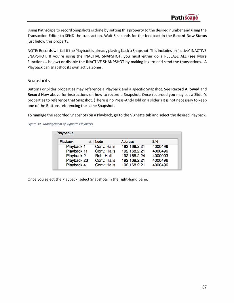
To manage the recorded Snapshots on a Playback, go to the Vignette tab and select the desired Playback.
Figure 30 - Management of Vignette Playbacks
Once you select the Playback, select Snapshots in the right-hand pane:

38
Figure 31 - Snapshot Management
The DMX Levels window will be empty until you enter a Snapshot Number and press Load Snaphot. You
can then Enter a Name and turn off the undesired universes if needed.
When Snapshots are recalled from buttons, any active Snapshot on the same Playback will fade out as
the new one fades in. Set this fade time here. Snapshots that are recalled from Sliders do not use the
fade time.
You can double click on any cell and change its level.
Be sure to Send Snapshot before leaving this screen or loading another Snapshot.
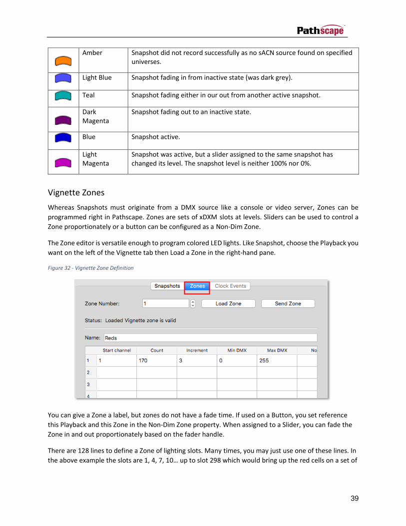
Table 5 – Vignette Snapshot Button Colors
Button Color Function
Dark Grey Snapshot is assigned to button, but not active.
Dark Blue Button is pressed during a Press-And-Hold-To-Record.
Green Snapshot recorded successfully.
39
Amber Snapshot did not record successfully as no sACN source found on specified universes.
Light Blue Snapshot fading in from inactive state (was dark grey).
Teal Snapshot fading either in our out from another active snapshot.
Dark Magenta
Snapshot fading out to an inactive state.
Blue Snapshot active.
Light Magenta
Snapshot was active, but a slider assigned to the same snapshot has changed its level. The snapshot level is neither 100% nor 0%.
Vignette Zones
Whereas Snapshots must originate from a DMX source like a console or video server, Zones can be
programmed right in Pathscape. Zones are sets of xDXM slots at levels. Sliders can be used to control a
Zone proportionately or a button can be configured as a Non-Dim Zone.
The Zone editor is versatile enough to program colored LED lights. Like Snapshot, choose the Playback you
want on the left of the Vignette tab then Load a Zone in the right-hand pane.
Figure 32 - Vignette Zone Definition
You can give a Zone a label, but zones do not have a fade time. If used on a Button, you set reference
this Playback and this Zone in the Non-Dim Zone property. When assigned to a Slider, you can fade the
Zone in and out proportionately based on the fader handle.
There are 128 lines to define a Zone of lighting slots. Many times, you may just use one of these lines. In
the above example the slots are 1, 4, 7, 10… up to slot 298 which would bring up the red cells on a set of

40
RGB LED lights. If you are just bringing up one dimmer, set the Start Channel and set the Count to 1 with
a Zero increment.
Each line can set the Min DMX and Max DMX for the zone. This is often 0 and 255, but not necessarily. If
for safety you must make sure the lighting levels do not go below a certain level, raise the minimum. If
you want to extend lamp life or save energy, lower the maximum value.
It is also possible to have the Min DMX higher than the Max DMX. This will invert the levels based on the
slider position. If you want one slider to crossfade between a red look and a blue look define a Zone like
this.
Figure 33 - Vignette Zone Editing
Note that in this example the Start Channels are offset by two. 1025 is the first slot on the third universe
(red cells) and 1027 is the third slot on that universe (blue cell). A setup like this gives you one slider to
set the color of the lights, but you will need to define a Grandmaster to affect the intensity of those
lights as this Zone definition cannot be deactivated; even at the bottom of travel, the Zone is outputting
levels (in this case, blue).2
If you have overlapping channels between two zones, note that live changes to zone levels are latest
takes precedent. That is, if one slider is at full and the other is at zero, when the second slider comes off
zero, the overlapping channels will quickly change from 100% to 1%.
Before leaving this view or loading another Zone, make sure to press the Send Zone button.
If a zone at level of zero (on slider) or off (on non-dim button), the LED will be . As the the level
gets closer to 100% it will get brighter. On a non-dim button, a zone that is on will be white .
Grandmaster
You can define either a Button or a Slider to be a Grandmaster for all Zone and Snapshot control on a
specified Playback. Note that with Buttons there is no fade time. When the Grand Master is at full, the
indicator LED will glow green . When not at full, it will be red .
2 See Blackout Zones below for a work around.

41
Record Allowed
A button can configured to toggle the Record Allowed property of a Playback as defined above in Playback
Properties. It will glow a very dim red when record is not allowed and glow red when record
is allowed.
Exclusive Lock
One of the Button Functions is Exclusive Lock which is useful during events (shows) where you do not
want the general public accidentally taking control of the lighting system. You can set up different wall
stations to have an Exclusive Lock button, but be cognizant that once activated, only that wall station will
be able turn off the Exclusive Lock. In a theatre, you may have one Exclusive Lock in the booth and one at
the Stage Managers panel. In a ballroom, you likely want to have it on a wall station in a service corridor
or facilities manager’s office.
When pressed, all the wall stations (except the one that has the Exclusive Lock button) on the specified
Playback will be muted; their LEDs will turn off and using them will have no effect on the lighting.
Remember that you can have different buttons on a single wall station set up to be on different Playbacks.
That means that during an Exclusive Lock event, only some of the buttons on a station may be disabled.
This can be a powerful programming tool as it allows you to lock out some lights (like step lights and egress
areas) but leave the clients some level of control of other parts of the room. To do this you will need to
allocate more than one Playback to this space.
Exclusive Lock buttons will glow dark amber when configured but inactive and bright amber
when active.
Blackout Zones
As mentioned above, it is possible to define a zone where its minimum level is above zero. In such a case,
you cannot position a slider or non-dim button to turn off the zone; once activated, it will continue to
output levels. Pressing this button will deactivate all Zone on the specified Playback, regardless of Slider
position.
Define a button on the network to have the function Blackout Zone and it will be yellowish in color.
Goto Inactive
Use the button to turn off any Snapshots that are active on the specified Playback. It will not affect Zones.
If there is an Inactive Snapshot recorded (see Playback Properties above), this Snapshot will fade in when
this button is pressed. If no Inactive Snapshot is defined, only active Zones will be output. If no zones are
active, the Playback will cease outputting sACN once the active Snapshot has completely faded out.
Define a button on the network to have the function Goto Inactive and it will be yellowish in color.

42
Release All
This function turns off all active Zones and Snapshots, including the Inactive Snapshot if defined. Be
careful, it will get dark!
Define a button on the network to have the function Release All and it will be yellowish in color.
Priority Override
In the Playback’s properties, there are two sACN priorities: Normal Output Priority and Override Output
Priority. Valid sACN priority values are between 1 (low priority) and 200 (high). A button defined as a
Priority Override will toggle between the two values as defined in the Playback’s properties. A typical
theatrical setup may have Vignette’s Normal Priority set to 90, below the theatrical consoles priority of
100 and have an Override Priority set to 110, just over the console’s. That way, when the console is on, it
‘wins’, but if you toggle the Priority Override, Vignette will win back control.
When Priority Override is inactive (normal priority) the button will be coral in color. When active, it
will be pink .
Vignette Clock
A Vignette Clock is a separate eDIN device that can trigger Vignette events based on a schedule or
astronomical events. Each Clock has one Playback available to the network, but events defined in the
schedule can trigger its own Playback or any other Playback on the network. Any function that a button
can have may be triggered by the clock.
If using the Clock’s Playback, select the 1001 Subdevice in the Devices tab set its sACN and Playback
properties.
Selecting the main Clock devices will expose many properties that other devices on the network have,
such as IP settings, firmware version, names and labels. See Ethernet Device Properties for details.
Clock Properties
The System Time Zone must be set as this handles Day Light Savings Time rules and properly offsets from
universal time. A Sync System Time will grab the time from the PC running Pathscape. If the Clock is going
to be on a network connected to the Internet, you can also specify a NTP Server so the Clock is always in
perfect time. If using an NTP Server, ensure that the DNS Server and IP Gateway are set so the Clock
knows how to get to the Internet to find a time server.
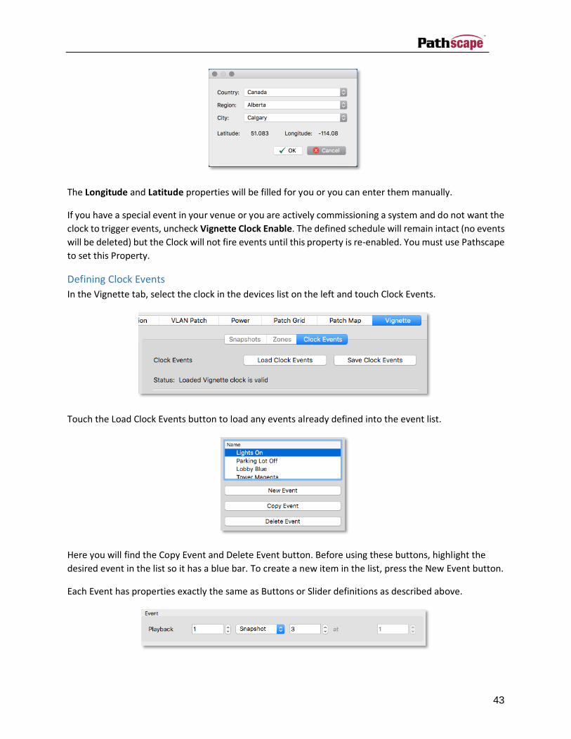
To properly predict astronomical events (sunrise, sunset) you must press the Set Lat/Long By City
button in the Clock’s properties and choose the city the venue is in or one very close to it.
43
The Longitude and Latitude properties will be filled for you or you can enter them manually.
If you have a special event in your venue or you are actively commissioning a system and do not want the
clock to trigger events, uncheck Vignette Clock Enable. The defined schedule will remain intact (no events
will be deleted) but the Clock will not fire events until this property is re-enabled. You must use Pathscape
to set this Property.
Defining Clock Events
In the Vignette tab, select the clock in the devices list on the left and touch Clock Events.
Touch the Load Clock Events button to load any events already defined into the event list.
Here you will find the Copy Event and Delete Event button. Before using these buttons, highlight the
desired event in the list so it has a blue bar. To create a new item in the list, press the New Event button.
Each Event has properties exactly the same as Buttons or Slider definitions as described above.

44
In this case, the “at 1” is greyed out as you cannot set the level of a Snapshot on an event. If you were
triggering a Zone, the “at” edit box will be inactive and you can set a level (0-255). The same if true for
other functions like Grandmaster level (0-255) or Record Allowed (0 or 1).
The best way to illustrate the how to set the time parameters is by using multiple examples.
Every Christmas Day at 9AM
Weekend lunch time

45
Top of the hour during work
Every 15 minutes between 8AM and 8PM
Just before Sunset

46
Odd days during the summer months at 12:20PM
Vignette Videos
For the latest information and “how-to” videos for Vignette, check out the Vignette Videos page at:
www.pathwayconnect.com/index.php/support/videos/181-vignette-videos.

47
Ethernet Device Properties
The Properties pane is the primary reporting and configuration tool of Pathscape. The options shown are
dependent on selections made in the Main Window.
Each device has its own set of modifiable properties and they vary, depending on device or subdevice.
Properties are modified with a variety of controls, depending on the property data type. Strings are edited
using text boxes, flags are set with check boxes, and enumerated types are changed using drop down list
controls.
It should be noted here that any property changes that are made in the Properties pane only creates a
‘transaction’ which must be sent to the devices for the change to take effect. Until the transaction has
been sent, the background of the edited property control is displayed in yellow. Note, you commit the
change (press enter or tab) before it turns yellow.
Figure 34 - Properties Pane
Figure 35 - Transaction Editor

48
Via Switch Properties
Not all properties are supported by all VIA models. Only the properties supported by the selected switch
will be shown in the Properties Pane. Some properties depend are dependent on each other so if you see
a property in this list but not in Pathscape, you may need to ‘enable’ a parent property.
Table 6 - Switch Properties
Property Options/Description
Basic Properties
VIA Name
A user-set, soft label for the device. If left blank (and by default) the device name displayed will be the device’s IP Address.
Shown on the front LCD of 6730 and 674x models.
VIA Notes A user-set text description field, shown in the Device tab of Pathscape.
User ID A user-set numeric field.
MAC Address Read Only. Factory-set unique identifier. Read-only.
Firmware Version Read Only. Current operating firmware version. Read-only. See the Firmware Update section on how to update the firmware.
Identify Device Setting causes VIA to commence identify behavior (flashing LCD backlight, Identify LED).
Serial Number Read Only. Factory-set unique identifier.
Network Properties
IP Address User-set Internet Protocol address (IPv4) for this switch. If VLANs are enabled, the IP address is applied by default to the Management VLAN ID#.
Subnet Mask User-set subnet mask. If VLANs are enabled, the subnet mask is used by default by the Management VLAN ID#.
Default Gateway Network traffic on this switch (or VLAN if enabled) requesting addresses outside of the assigned subnet will be routed through this IP address.

49
Quality of Service
Disabled (default)
Standard. Traffic routed using a weighted algorithm to ensure timely delivery of high priority and eventual delivery of lower priority traffic.
Dante Strict. Priority is strictly observed, using Dante-specific weighting. Lower priority traffic may be dropped or ignored to ensure delivery of Dante’s high priority packets.
VLAN Properties
Enable VLANs
Disabled (default). In most cases, equivalent to all ports using VLAN ID# as untagged ports.
Enabled. Required to allow certain VLAN-based services and features such as EAPS Ring Protect.
VLAN Range Start Sets lowest available VLAN ID#. Default is ID#1
VLAN Range End Sets highest available VLAN ID#. Maximum value is 4095. Default is ID#10. The range should be kept as small as possible.
Management VLAN ID
Specifies the VLAN ID# used by the switch’s management processor. Default is 1 or the lowest VLAN ID# in the range specified. This value MUST be within the VLAN range specified or it will not be possible to configure the switch.
DMX Properties
Art-Net Alternate Mapping
Enabled (by default). Used in conjunction with Art-Net trap-and-convert (see Port Properties). When enabled, Art-Net universe 0-0 is treated as Universe 1. When disabled, Art-Net universe 0-0 is ignored. Does not affect unicast Art-Net packets.
Ring Protect Properties
Ring Protect Mode
Disabled (default). Not supported by VIA5 models.
Enabled. Allows VIA switches to be connected in a physical wiring ring using EAPS (Ethernet Automatic Protection Switching. See Ring Protection).
Ring Protect Control VLAN Specifies dedicated Ring Protect VLAN. Valid range is 1 – 4095. Use of the default (4095) is strongly

50
recommended. The Ring Protect VLAN must to be outside of defined VLAN range.
Ring Protect Primary Port
Models 6740, 6741, 6742: Select from Ports 11, 12, 13 or 14.
Model 6730: Select from Ports 9, 10 or 11.
Ring Protect Secondary Port
Models 6740, 6741, 6742: Select from Ports 11, 12, 13 or 14.
Model 6730: Select from Ports 9, 10 or 11.
RSTP
Rapid Spanning Tree Protocol automatically detects Ethernet loops (two Cat5 cables between the same two switches where the ports are on the same VLAN). Without RSTP on, networks with loops will have very poor performance.
POE Properties
PoE External Supply Present
Not selected (not present) by default. The user must set this value when an external PoE supply is added. Via 10 Switches have 60W of internal PoE but also have an optional external power supply.
Advanced Properties
User ID Custom numeric identification for external databases.
51
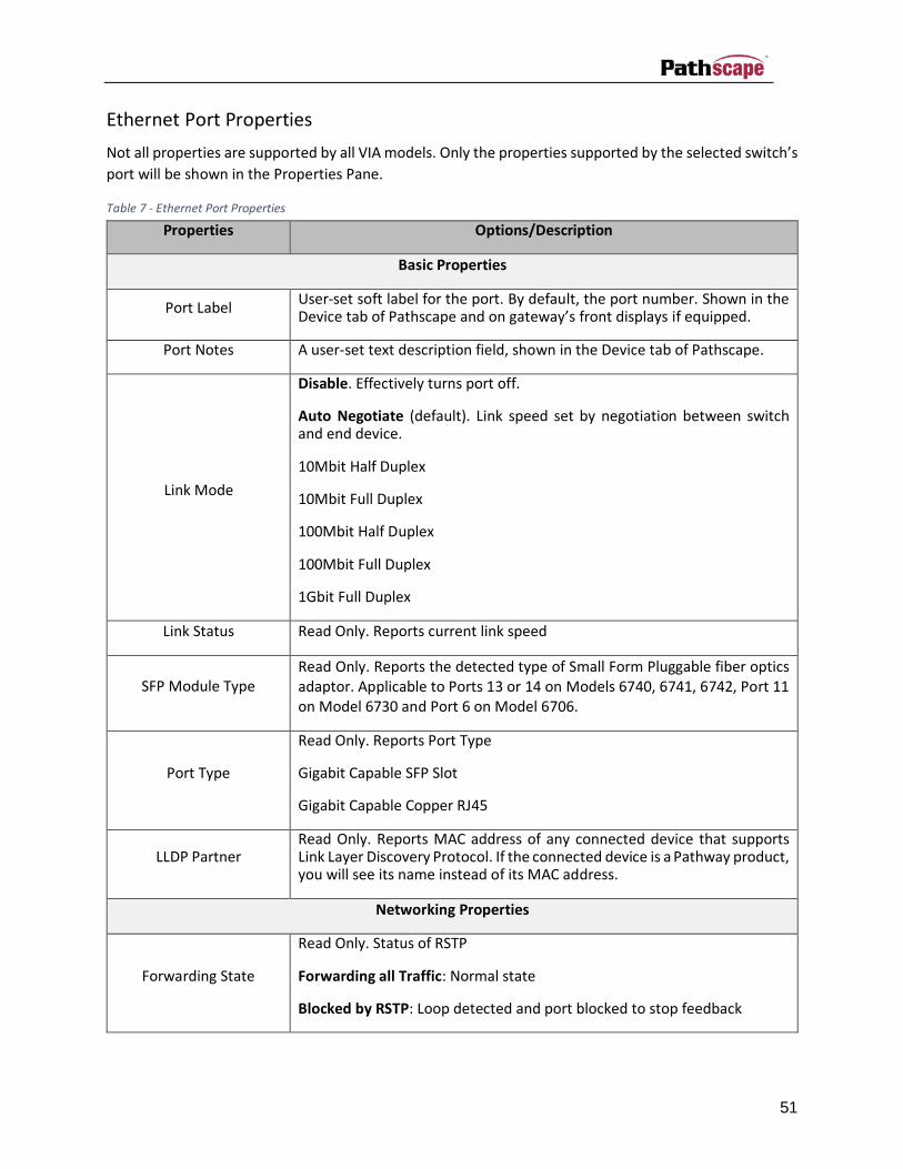
Ethernet Port Properties
Not all properties are supported by all VIA models. Only the properties supported by the selected switch’s
port will be shown in the Properties Pane.
Table 7 - Ethernet Port Properties
Properties Options/Description
Basic Properties
Port Label User-set soft label for the port. By default, the port number. Shown in the Device tab of Pathscape and on gateway’s front displays if equipped.
Port Notes A user-set text description field, shown in the Device tab of Pathscape.
Link Mode
Disable. Effectively turns port off.
Auto Negotiate (default). Link speed set by negotiation between switch and end device.
10Mbit Half Duplex
10Mbit Full Duplex
100Mbit Half Duplex
100Mbit Full Duplex
1Gbit Full Duplex
Link Status Read Only. Reports current link speed
SFP Module Type Read Only. Reports the detected type of Small Form Pluggable fiber optics adaptor. Applicable to Ports 13 or 14 on Models 6740, 6741, 6742, Port 11 on Model 6730 and Port 6 on Model 6706.
Port Type
Read Only. Reports Port Type
Gigabit Capable SFP Slot
Gigabit Capable Copper RJ45
LLDP Partner Read Only. Reports MAC address of any connected device that supports Link Layer Discovery Protocol. If the connected device is a Pathway product, you will see its name instead of its MAC address.
Networking Properties
Forwarding State
Read Only. Status of RSTP
Forwarding all Traffic: Normal state
Blocked by RSTP: Loop detected and port blocked to stop feedback
52
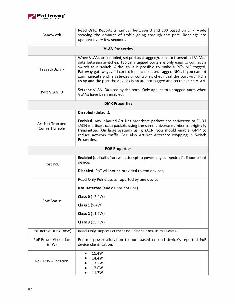
Bandwidth Read Only. Reports a number between 0 and 100 based on Link Mode showing the amount of traffic going through the port. Readings are updated every few seconds.
VLAN Properties
Tagged/Uplink
When VLANs are enabled, set port as a tagged/uplink to transmit all VLANs’ data between switches. Typically tagged ports are only used to connect a switch to a switch. Although it is possible to make a PC’s NIC tagged, Pathway gateways and controllers do not used tagged NICs. If you cannot communicate with a gateway or controller, check that the port your PC is using and the port the devices is on are not tagged and on the same VLAN.
Port VLAN ID Sets the VLAN ID# used by the port. Only applies to untagged ports when VLANs have been enabled.
DMX Properties
Art-Net Trap and Convert Enable
Disabled (default).
Enabled. Any inbound Art-Net broadcast packets are converted to E1.31 sACN multicast data packets using the same universe number as originally transmitted. On large systems using sACN, you should enable IGMP to reduce network traffic. See also Art-Net Alternate Mapping in Switch Properties.
POE Properties
Port PoE
Enabled (default). Port will attempt to power any connected PoE-compliant device.
Disabled. PoE will not be provided to end devices.
Port Status
Read-Only PoE Class as reported by end device.
Not Detected (end device not PoE)
Class 0 (15.4W)
Class 1 (5.4W)
Class 2 (11.7W)
Class 3 (15.4W)
PoE Active Draw (mW) Read-Only. Reports current PoE device draw in milliwatts.
PoE Power Allocation (mW)
Reports power allocation to port based on end device’s reported PoE device classification.
PoE Max Allocation
• 15.4W • 14.4W • 13.5W • 12.6W • 11.7W

53
• 10.8W • 9.9W • 9.0W • 8.1W • 7.2W • 6.3W • 5.4W • 4.5W • 3.6W • 2.7W • 1.8W • 900mW
Sets power allocated to port. Allows switch to determine remaining PoE power pool available, but does not prevent end devices from requesting and utilizing power in excess of this value.
VLAN Properties/Services
VLANs must be enabled prior to configuring these services. You will find the VLAN Enable/Disable property
by selecting the switch’s base properties in the DEVICES tab.
Table 8 - VLAN Properties/Services
Properties Options/Description
Networking Properties
IP Mode
Disabled. No IP assigned to this VLAN by this VIA
Static. IP settings manually set by user (default for VLAN ID#1 / management VLAN). You must set a Static IP address if you want to enable DHCP and/or IGMP on this VLAN.
Dynamic. IP settings obtained from DHCP server.
IP Address User-set Internet Protocol address (IPv4) for this switch on the selected VLAN
Subnet Mask User-set subnet mask applied to VLAN.
Default Gateway Network traffic on this VLAN requesting addresses outside of the assigned subnet will be routed through this IP address.
VLAN Name The name of the VLAN is used on the front panel of the selected switch (if equipped with a front panel display). Changing the name on one switch does not change the corresponding VLAN ID’s name on other switches.
DHCP Properties

54
DHCP Server Enable
Dynamic Host Configuration Protocol (DHCP)
Disabled (default).
Enabled. Only one switch on a given VLAN may have an active DHCP service, and that VLAN must have a static IP itself. One switch with multiple VLANs may have multiple DHCP servers.
DHCP Server Range Start Sets start IP address in the DHCP pool. Pool must begin at an address higher than the IP address of the sever
DHCP Server Range End Sets last available IP address in the DHCP pool. Cannot exceed the last valid IP value in the IP/Subnet Mask range.
IGMP Properties
IGMP Querier
Intergroup Management Protocol (IGMP) allows for packet filtering and forwarding by the switch based on multicast groups. Networks using sACN can take full advantage of IGMP by reducing the traffic on the link to the gateway to just the xDMX universes the gateway is configured to listen to.
Disabled (default).
Enabled. Allows switch to query and construct a forwarding-table based on end device subscriptions to multicast group addresses. (i.e., the Querier can tell that a 2-port DMX512 gateway is interested in Univ8 and Univ37, if so patched, and will route those sACN universe, and only those, on the link on which the gateway is connected.) One querier is required be active on a given VLAN using IGMP routing. However, for reliability reasons, it is highly recommended to have two or more.
IGMP Snooping
Disabled (default)
Enabled. Allows the switch to forward multicast data packets according to IGMP forwarding-tables build by the Querier. All switches on a VLAN using IGMP should have snooping enabled, including the switches acting as an IGMP Querier.

55
Pathport Gateway Properties
There are many versions of the Pathport Ethernet to DMX512/RDM gateway. Not all properties are
supported by all models. Only the properties supported by the selected gateway’s port will be shown in
the Properties Pane.
Table 9 - Gateway Properties
Properties Options/Description
Basic Properties
Name A user-set, soft label for the gateway. If left blank (and by default) the device name displayed will be the device’s IP Address. Shown in the Device tab of Pathscape and on gateway front displays if equipped.
Notes A user-set text description field, shown in the Device tab of Pathscape.
MAC Address Factory-set unique identifier. Read-only.
Firmware Version Current operating firmware version. Read-only. See the Firmware Update section on how to update the firmware.
Identify Device Setting causes gateway to commence identify behavior (flashing LCD backlight, Identify or Processor LED).
Serial Number Factory-set unique identifier.
Front Panel Lockout On Octo and Quattro and TE gateways locks the local controls. Scrolling menus allow you to still read properties, but changing properties is disallowed.
LCD Backlight Turns on or off display backlight.
LED Intensity Uno only. Either Dim or Bright.
Network Properties
IP Address Internet Protocol address (IPv4).
Subnet Mask User-set subnet mask. Typically, 255.255.255.0 but must be set according to general networking rules.
Default Gateway Rarely used on gateways.
DMX Properties
Receive Protocol
Four properties to determine which protocols to receive and pushed to output ports (if any ports on the gateway are configured as outputs). Receiving all four is valid. Slots in the xDMX world will be patched to Output ports as defined in the Patch Map or Patch Grid. See Priorities and HTP in
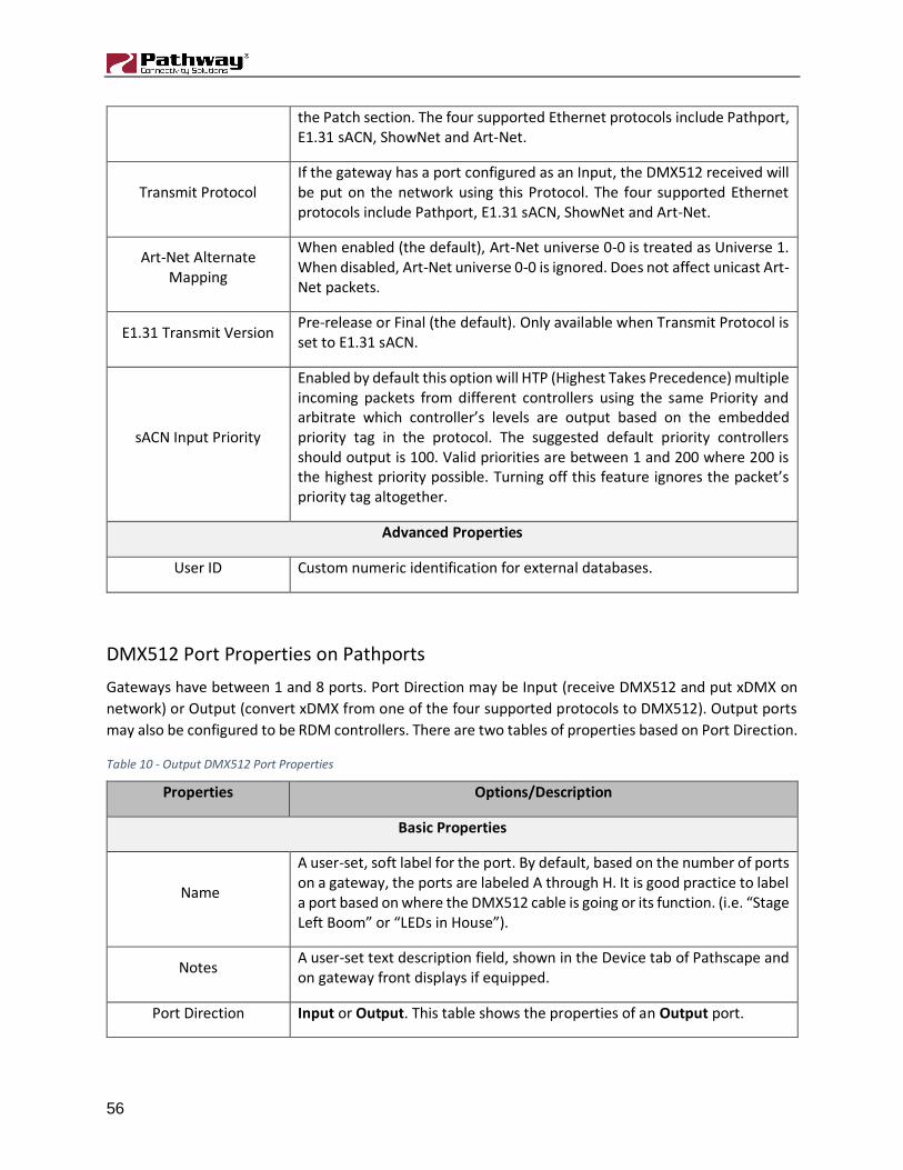
56
the Patch section. The four supported Ethernet protocols include Pathport, E1.31 sACN, ShowNet and Art-Net.
Transmit Protocol If the gateway has a port configured as an Input, the DMX512 received will be put on the network using this Protocol. The four supported Ethernet protocols include Pathport, E1.31 sACN, ShowNet and Art-Net.
Art-Net Alternate Mapping
When enabled (the default), Art-Net universe 0-0 is treated as Universe 1. When disabled, Art-Net universe 0-0 is ignored. Does not affect unicast Art-Net packets.
E1.31 Transmit Version Pre-release or Final (the default). Only available when Transmit Protocol is set to E1.31 sACN.
sACN Input Priority
Enabled by default this option will HTP (Highest Takes Precedence) multiple incoming packets from different controllers using the same Priority and arbitrate which controller’s levels are output based on the embedded priority tag in the protocol. The suggested default priority controllers should output is 100. Valid priorities are between 1 and 200 where 200 is the highest priority possible. Turning off this feature ignores the packet’s priority tag altogether.
Advanced Properties
User ID Custom numeric identification for external databases.
DMX512 Port Properties on Pathports
Gateways have between 1 and 8 ports. Port Direction may be Input (receive DMX512 and put xDMX on
network) or Output (convert xDMX from one of the four supported protocols to DMX512). Output ports
may also be configured to be RDM controllers. There are two tables of properties based on Port Direction.
Table 10 - Output DMX512 Port Properties
Properties Options/Description
Basic Properties
Name
A user-set, soft label for the port. By default, based on the number of ports on a gateway, the ports are labeled A through H. It is good practice to label a port based on where the DMX512 cable is going or its function. (i.e. “Stage Left Boom” or “LEDs in House”).
Notes A user-set text description field, shown in the Device tab of Pathscape and on gateway front displays if equipped.
Port Direction Input or Output. This table shows the properties of an Output port.

57
Gender Read only. C-Series, TE, Uno, Quattros and Octo gateways may be equipped with either XLRM or XLRF jacks.
DMX Properties
DMX Port Enabled
For debugging purposes or otherwise, you may want to disable a DMX port. All other properties will remain unchanged. Apart from the fact that the line is still terminated, this is electrically equivalent to unplugging the DMX512 cable.
DMX Status Read only. Active when the gateway is receiving xDMX and this port has a patch that is using the xDMX data.
Patch Name Read only in the tab. Set in Patch Map (Right Click and Rename Output Group) or Patch Grid’s Group column.
DMX Output Speed ANSI E1.11 compliant devices should be able to receive at Maximum speed (42 Hz), but some devices may require you to lower the number of DMX512 packets per second. The slowest rate is 30 Hz.
E1.31 sACN Per Channel Priority
In the Gateway DMX Properties, there is sACN Input Priority which determines if the gateway respects the priority (1-200) in the universe header. This property extends that to each slot in the universe. It is off by default.
Crossfade Enable If a Priority changes either as defined by the Pathscape DMX Patch Priorities or the E1.31 sACN Priority, the gateway will fade rather than snap to the new levels. The last frame of the old source is frozen during the fade.
Crossfade Time (ms) As defined above in Crossfade Enable
Signal Loss Hold Time If Signal Loss Fade or Signal Loss Port Shutdown is enabled, the port will continue outputting the last packet it received until this time has expired.
Signal Loss Hold Forever If enabled, Signal Loss Hold Time, Signal Loss Fade and Signal Loss Port Shutdown are ignored.
Signal Loss Fade If the xDMX stream ceases, all 512 slots of the DMX512 will fade to a value of 0%.
Signal Loss Fade Time Applicable when Signal Loss Fade is enabled.
Signal Loss Port Shutdown
If the xDMX stream ceases and Signal Loss Hold Forever is not enabled and the Signal Loss Fade Time has expired, the port will ‘turn off’. Apart from the fact that the line is still terminated, this is electrically equivalent to unplugging the DMX512 cable.
RDM Properties
E1.20 RDM Enabled Pathscape is a very powerful RDM controller that allows you to identify RDM devices and set properties like mode and starting address as well as
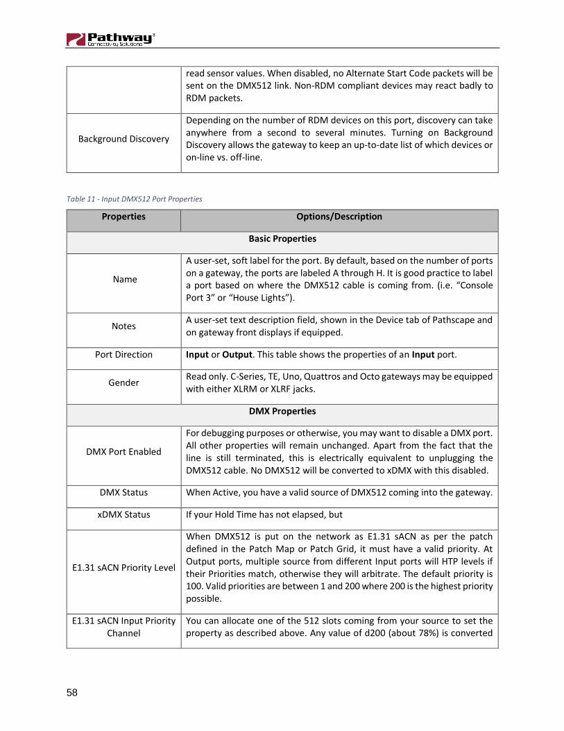
58
read sensor values. When disabled, no Alternate Start Code packets will be sent on the DMX512 link. Non-RDM compliant devices may react badly to RDM packets.
Background Discovery
Depending on the number of RDM devices on this port, discovery can take anywhere from a second to several minutes. Turning on Background Discovery allows the gateway to keep an up-to-date list of which devices or on-line vs. off-line.
Table 11 - Input DMX512 Port Properties
Properties Options/Description
Basic Properties
Name
A user-set, soft label for the port. By default, based on the number of ports on a gateway, the ports are labeled A through H. It is good practice to label a port based on where the DMX512 cable is coming from. (i.e. “Console Port 3” or “House Lights”).
Notes A user-set text description field, shown in the Device tab of Pathscape and on gateway front displays if equipped.
Port Direction Input or Output. This table shows the properties of an Input port.
Gender Read only. C-Series, TE, Uno, Quattros and Octo gateways may be equipped with either XLRM or XLRF jacks.
DMX Properties
DMX Port Enabled
For debugging purposes or otherwise, you may want to disable a DMX port. All other properties will remain unchanged. Apart from the fact that the line is still terminated, this is electrically equivalent to unplugging the DMX512 cable. No DMX512 will be converted to xDMX with this disabled.
DMX Status When Active, you have a valid source of DMX512 coming into the gateway.
xDMX Status If your Hold Time has not elapsed, but
E1.31 sACN Priority Level
When DMX512 is put on the network as E1.31 sACN as per the patch defined in the Patch Map or Patch Grid, it must have a valid priority. At Output ports, multiple source from different Input ports will HTP levels if their Priorities match, otherwise they will arbitrate. The default priority is 100. Valid priorities are between 1 and 200 where 200 is the highest priority possible.
E1.31 sACN Input Priority Channel
You can allocate one of the 512 slots coming from your source to set the property as described above. Any value of d200 (about 78%) is converted

59
to a priority of 200. Zero values are converted to priority 1, the lowest priority in E1.31.
Input Signal Loss Hold Time
If the DMX512 source ceases, the xDMX will continue to be refreshed to the network using the levels from the last packet the gateway received until this timer expires.
NSB and Vignette Properties (Stations and Gateways)
NSB (Network Sliders and Buttons) and Vignette each have PoE Stations and 485 Gateways which share
similar properties. Their sub-devices (buttons and sliders) each have differing properties which will be
outline in subsequent tables below this one.
Table 12 – Gateway & PoE Master Properties
Properties Options/Description
Basic Properties
Name
A user-set, soft label for the wall station or gateway. If left blank (and by default) the device name displayed will be the device’s IP Address. Shown in the Device tab of Pathscape and should refer to the device’s physical location. (i.e., ‘eDIN Utility Room’, ‘South Hall’)
Notes A user-set text description field, shown in the Device tab of Pathscape.
MAC Address Read only. Factory-set unique identifier.
Firmware Version Read only. Current operating firmware version. See the Firmware Update section on how to update the firmware.
Identify Device Setting causes device to commence identify behavior (flashing backlights on buttons and sliders or Identify LED on gateway).
Serial Number Factory-set unique identifier.
Network Properties
IP Mode
Disabled. No IP assigned to this device
Static. IP settings manually set by user
Dynamic. IP settings obtained from DHCP server.
IP Address User-set Internet Protocol address (IPv4) for this device.
Subnet Mask User-set subnet mask.
Default Gateway Rarely used on NSB and Vignette

60
Status
Station Sub-Device Count
Read-only. For gateways this is the number buttons on the right-hand side of the eDIN device (if any). It is not the number of wall stations on the buses.
For PoE wall station it is the total number of buttons and sider on both the Master insert and the Slaves.
Vignette Button Properties
NSB Buttons only have a Name and a Status (pressed or unpressed). Below is the list of all the properties
of a Vignette button. See the Vignette section of this manual for more information on Button functions.
Table 13 – Vignette Button Properties
Properties Options/Description
Basic Properties
Name A user-set, soft label for the button.
Button Properties
Function
None. The Button will have no function. Any other properties will be hidden.
Snapshot. (Radio/Toggle) Button will trigger specified Playback to output specified Snapshot. Snapshots, as edited in the Vignette tab, have universes, levels and fade times.
Non-Dim Zone. (Toggle) Button will turn on or off the specified zone on the specified Playback. Zones are edited in the Vignette tab. Non-Dims do not have a fade time.
Grandmaster. (Toggle) The button will act as a Dead Blackout for the specified Playback’s output. There is no fade time associated with Grandmaster Buttons.
Allow Record. (Toggle) When active (bright red is active, dim red is inactive) the specified Playback will snapshot incoming xDMX universes when a Snapshot button is held down for 5 seconds.
Exclusive Lock. (Toggle) When pressed (amber), all other wall station on the specified Playback will be disabled. Define an Exclusive Lock button on the wall station that is a secure area (booth; security office; house managers position) to prevent unauthorized changes to the lighting system during shows times.
Blackout Zones. (Momentary) When pressed, all Zones on the specified playback will be deactivated. Zones can be assigned to buttons and sliders
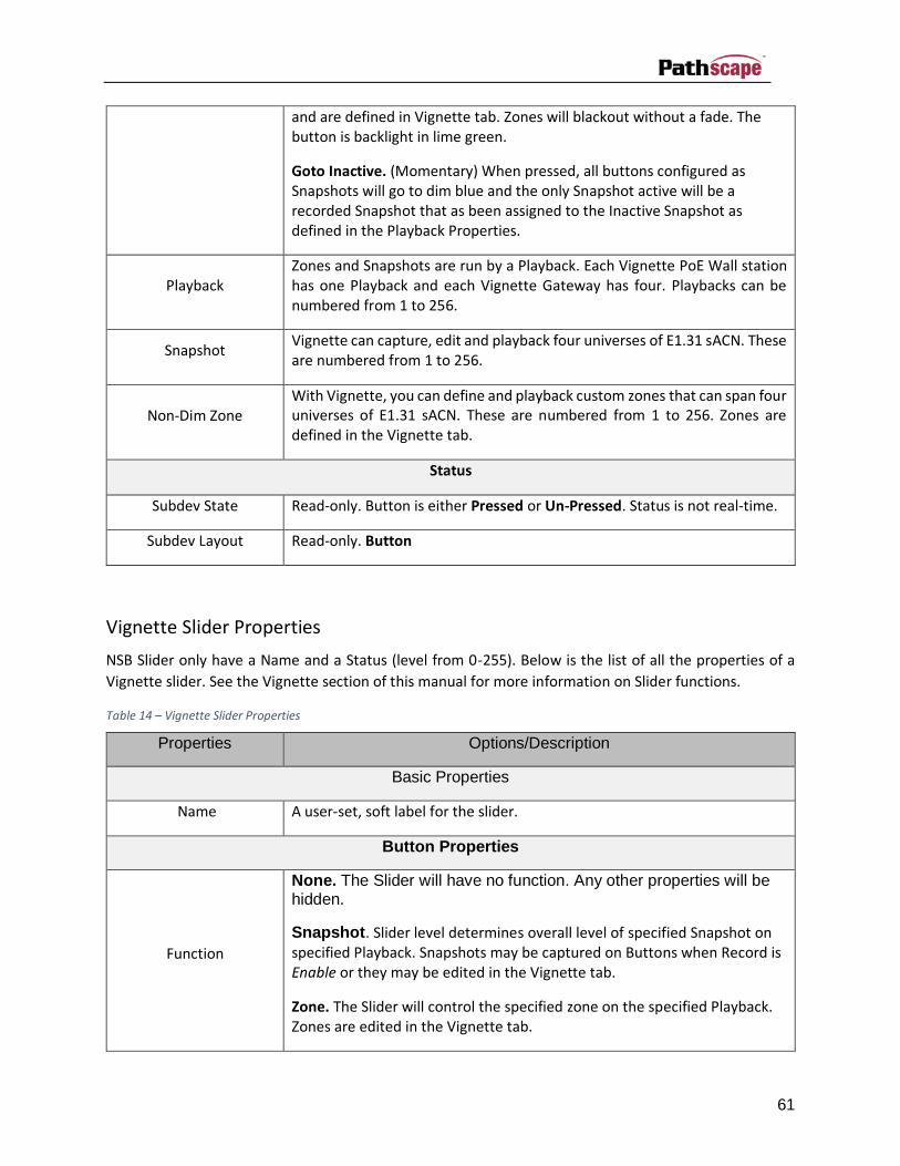
61
and are defined in Vignette tab. Zones will blackout without a fade. The button is backlight in lime green.
Goto Inactive. (Momentary) When pressed, all buttons configured as Snapshots will go to dim blue and the only Snapshot active will be a recorded Snapshot that as been assigned to the Inactive Snapshot as defined in the Playback Properties.
Playback Zones and Snapshots are run by a Playback. Each Vignette PoE Wall station has one Playback and each Vignette Gateway has four. Playbacks can be numbered from 1 to 256.
Snapshot Vignette can capture, edit and playback four universes of E1.31 sACN. These are numbered from 1 to 256.
Non-Dim Zone With Vignette, you can define and playback custom zones that can span four universes of E1.31 sACN. These are numbered from 1 to 256. Zones are defined in the Vignette tab.
Status
Subdev State Read-only. Button is either Pressed or Un-Pressed. Status is not real-time.
Subdev Layout Read-only. Button
Vignette Slider Properties
NSB Slider only have a Name and a Status (level from 0-255). Below is the list of all the properties of a
Vignette slider. See the Vignette section of this manual for more information on Slider functions.
Table 14 – Vignette Slider Properties
Properties Options/Description
Basic Properties
Name A user-set, soft label for the slider.
Button Properties
Function
None. The Slider will have no function. Any other properties will be hidden.
Snapshot. Slider level determines overall level of specified Snapshot on specified Playback. Snapshots may be captured on Buttons when Record is Enable or they may be edited in the Vignette tab.
Zone. The Slider will control the specified zone on the specified Playback. Zones are edited in the Vignette tab.

62
Grandmaster. The Slider will act as a master for the specified Playback’s output.
Playback Zones and Snapshots are run by a Playback. Each Vignette PoE Wall station has one Playback and each Vignette Gateway has four. Playbacks can be numbered from 1 to 256.
Snapshot Vignette can capture, edit and playback four universes of E1.31 sACN. These are numbered from 1 to 256.
Zone With Vignette, you can define and playback custom zones that can span four universes of E1.31 sACN. These are numbered from 1 to 256. Zones are defined in the Vignette tab.
Status
Subdev State Read-only. Shows the current level of the Slider from 0-255. Status is not real-time.
Subdev Layout Read-only. Slider
Vignette Playback Properties
Zones and Snapshots are run by a Playback. Each Vignette PoE Wall station has one Playback and each
Vignette Gateway has four. Playbacks can be numbered from 1 to 256. Button and Slider must reference
a Playback, but not necessarily a Playback on their own device. Playbacks are available across the whole
network. For example, a PoE Wall station that has four buttons may use a Playback on a Gateway
elsewhere on the network versus its own.
Table 15 – Vignette Button Properties
Properties Options/Description
DMX Properties
Start Universe for Capture
These are the four consecutive universes that the Playback will listen on when snapshotting scenes.
Start Universe for Output
The four universes that the Playback will output to when playing back Snapshots or Zones. By editing the Snapshot, you can toggle on or off any of the specified four universes.
Number of Universes
This value can be between 1 and 4. By editing the Snapshot, you can toggle on or off any of the specified four universes.

63
Lockout: Listen for Universe
None zero if active. If specified, when Vignette senses an active sACN source at this universe, all buttons and sliders assigned to this Playback will become inactive (their LEDs will turn off)
sACN Output Priority
E1.31 sACN packets are tagged with a priority from 1 to 200, where 200 is the highest (most important) priority. Gateways that respect the sACN Priority will arbitrate between multiple sources and the one with the highest priority will ‘win’. Vignette’s default priority is 90. Most lighting console will use the standard’s recommended priority of 100. That means a gateway that is listening to a console and a Vignette will allow the console to ‘win’ when it’s on and the Vignette architectural controller to win when the console is not present.
Playback Properties
Allow Record When active the specified Playback will snapshot incoming xDMX universes when a Snapshot button is held down for 5 seconds. Buttons can set their Function to toggle this Allow Record Property.
Playback
Playbacks must be uniquely identified on the network. If you see flashing Button or Sliders, it’s likely two Playbacks on the network are using the same identifying number. Playbacks can be numbered from 1 to 256. Set a Playback to 0 to disable it. Some PoE Wall stations may not need an active Playback as its Buttons and Sliders are using another Playback on the network.
Startup Snapshot When the network is power cycled or is recovering from a brownout, this Snapshot may be automatically activated. Set it to zero so this Playback doesn’t activate a snapshot on boot.

64
Transaction Editor
Figure 36 - Transaction Editor
When a change is made to a property, a ‘transaction’ is created and queued in the Transaction Editor.
Until the transactions are sent, the new property in the property table will remain highlighted in yellow.
Selected items in the queue can be deleted, or the entire queue flushed.
The transaction table has four columns:
• Destination – the device and subdevice that the change is to be sent to
• Description – the name or description of the property that is to be changed
• Current Setting – the current value of the property
• New Setting – the new value of the property
There are four buttons below the table. The Send Transaction action button will send the entire queued
list of transactions to their respective destinations. Pathscape only keeps track of the last set of
transactions that were sent and therefore the Undo Transactions button will only reverse the last set of
transactions sent back to their previous state. If the last action was an ‘undo’, then the ‘undo’ itself will
be undone. The Undo Transaction button only becomes enabled after transactions have been sent to the
device.
The transaction editor is a multi-select table. You can select one row by clicking anywhere on a row, or
select multiple rows by clicking individually on each row, or select continuous rows using click and drag.
To de-select a row, simply click on the row again. Once rows are selected and highlighted, you can remove
those transactions from the list by clicking on the Remove Selected button. Remove all transactions in
the list by clicking on the Remove All button.

65
Message Viewer
Displays confirmation of transactions committed in the Transaction Monitor, as well as reports the
discovery and loss of devices on the network, as well as other error conditions.
Figure 37 - Message Viewer
The Message Viewer window consists of two edit boxes, two action buttons, and a message table. The
message table has a date column, a time column and a message column. Error or Warning messages are
in red.
If you wish to look for a word or phrase within the messages, type that information into either the “Filter
On:” box or the “Search For:” box.
The Search For function will look for the characters or words you type into the text box, and highlight the
first message containing that phrase. By clicking the Find Next button again, it will find and
highlight the next message containing that phrase.
The Filter On function will display only those lines that contain text matching what you enter in the text
box. The remainder of the lines will be hidden. Filtering remains in effect if the Filter On edit box contains
any text. As you change the text in the edit box, only messages that contain the text in the box will be
shown in the message view.
To turn off filtering, delete all text from the Filter On edit box with your delete/backspace key or by clicking
on the “X” button in the text field.

66
For example, if you type “Via” you may only see switches; if you type NSB, you may only see the Network
Sliders and Buttons. The Filter On text is not case-sensitive. Interesting Filter text may include:
• Stage Right
• Ballroom
• Octo (Device Type)
• 192.168.2 (part of an IP address)
The Clear Messages button erases all the messages from the message view.

67
Ethernet Main Menu
Ethernet File Menu
New Show
Discards all unsent transactions, patches and properties, re-discovers all devices and re-populates all
settings as they currently exist on the network.
Load Show
This command will bring up the standard open file dialog for your operating system and allow you to select
a saved show file to load setup properties for your show.
Open Recent
Shows a flyout menu, listing the 10 most recently opened Show Files.
Save Show
This command will bring up the standard save file dialog for your operation system and allow you to save
all your current setup properties to a file which can be saved and reloaded later.
Exit
Exits Pathscape.
View Menu
RDM Device View
Switches to RDM Device view to discover and set properties of RDM devices connected to Pathport Output
ports on your network. Devices will not be automatically discovered and populate this view when you
enter it. You must Discover devices on selected ports.
Hide Devices
Hides the selected device(s), removing them from the Devices view. The number of hidden subdevices
will be shown in the bottom status bar.
Show Hidden Devices
Shows any device(s) that were previously hidden.

68
Change Skin
This will change the UI color theme from light grey to dark grey. In low light settings, the darker theme
may be easier on the eyes. To switch back to the light grey theme, simply select this from the menu again.
Figure 38 - Dark Grey UI
Device Menu
Rediscover All Devices
The Rediscover all Devices command in the menu will attempt to discover all devices connected to the
currently enabled network interfaces. The current list of devices will be cleared from all trees and the
device information updated.
Identify Device
When the Identify Device command is selected, the currently selected device will ID itself by flashing its
LCD Panel backlight or Identify LED(s), to make identification among other connected equipment easy.
Un-identify Device
The Un-identify Device command will stop the Identify backlight flashing on any selected devices.
Copy Properties
Copies all Properties’ values for the selected Device or Port into the clipboard. Has no affect until you
select Paste Properties.

69
Paste Properties
Pastes the Properties onto the target Device or Port that were copied from another Device or Port using
the above ‘Copy Properties’ command. Note: the target Device or Port must be compatible, ie. It must be
the same type as the source. For example, you may copy the properties from one port on a VIA Switch
and paste it to another port on a VIA, but you cannot paste the properties to a port on an Octo.
Using this command creates a list of transactions in the Transaction Editor, which can then be reviewed
and edited before being sent with the ‘Send Transactions’ button.
Paste Special
This will bring up a dialog where you can choose which of the previously copied Properties you would like
to paste to the target device or port. Use the checkboxes to select or de-select which properties you’d like
to paste to the target.
Refresh Device
Selecting this command will refresh all property values for the currently selected device(s).
Reboot Device
Select this command to send a reboot command to the selected on-line device which will cause it to power
cycle. This will bring up a warning dialog which allows you to cancel the reboot. Select Yes to continue or
No to cancel the reboot.
Figure 39 - Reboot Device

70
Factory Defaults
This command will reset the selected device to its default factory settings. This will bring up a warning
dialog which allows you to cancel the factory default. Select Yes to continue or No to cancel the reset.
Figure 40 - Factory Defaults
Firmware Update
Select this command to update the firmware on the selected device. This command will bring up a dialog
which shows you the current version of the firmware and a dropdown list of all the available firmware
files.
Select the version of the firmware that you want to flash to the device and click on the Update button.
Figure 41 - Update Firmware
If new firmware is available on the website download it to your PC and import firmware files by clicking
on the Import Firmware button. This will bring up a standard file selection dialog to select a firmware file
and import it into Pathscape. The imported firmware file will then be available in the drop-down list for
subsequent firmware updates.
Refresh VLAN Properties
Populates or refreshes the information in the VLAN Configuration and VLAN Patch tab. It is best to have
all the switches on your network having the same VLAN setup and Tagged ports connecting from switch
to switch. See Network VLAN Settings below.
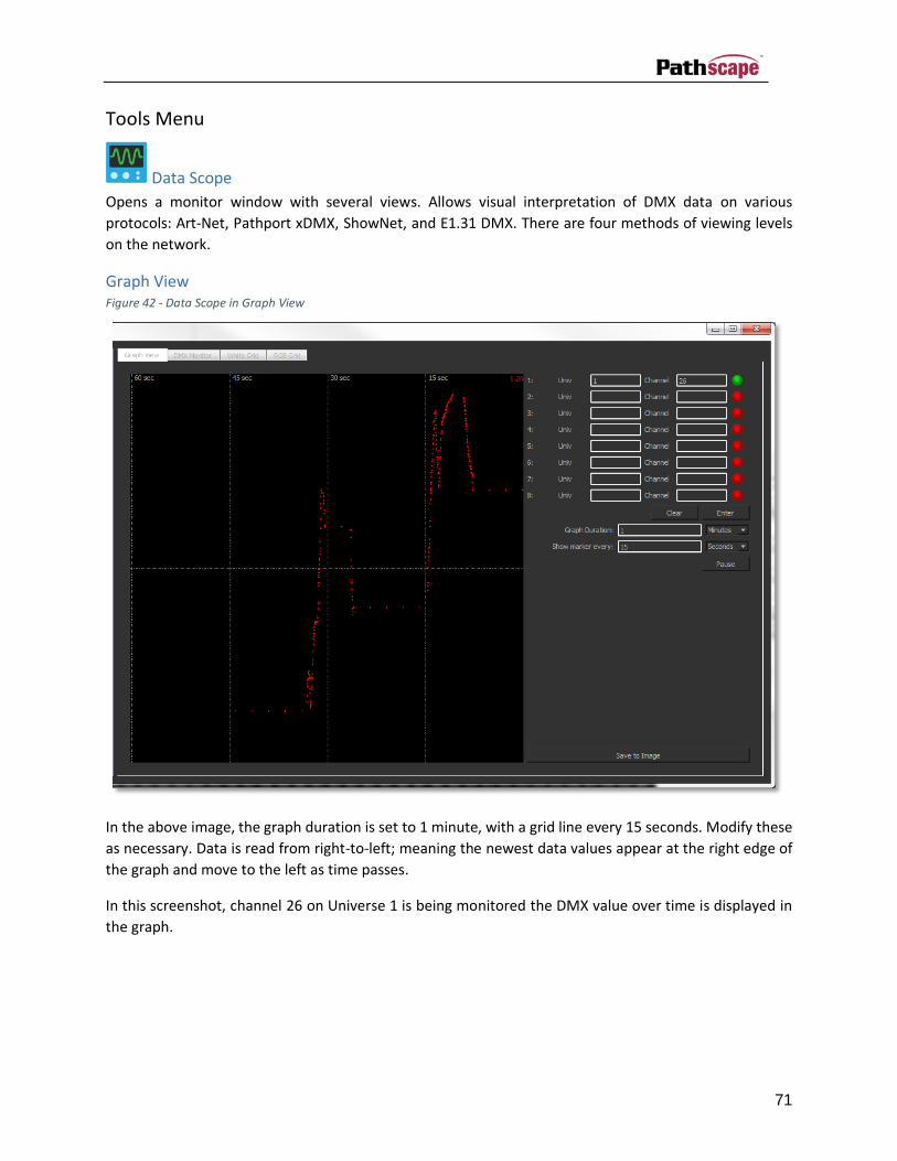
71
Tools Menu
Data Scope
Opens a monitor window with several views. Allows visual interpretation of DMX data on various
protocols: Art-Net, Pathport xDMX, ShowNet, and E1.31 DMX. There are four methods of viewing levels
on the network.
Graph View Figure 42 - Data Scope in Graph View
In the above image, the graph duration is set to 1 minute, with a grid line every 15 seconds. Modify these
as necessary. Data is read from right-to-left; meaning the newest data values appear at the right edge of
the graph and move to the left as time passes.
In this screenshot, channel 26 on Universe 1 is being monitored the DMX value over time is displayed in
the graph.
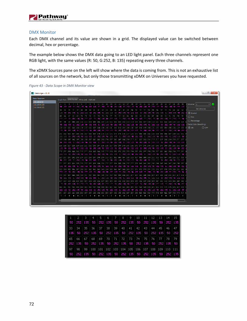
72
DMX Monitor
Each DMX channel and its value are shown in a grid. The displayed value can be switched between
decimal, hex or percentage.
The example below shows the DMX data going to an LED light panel. Each three channels represent one
RGB light, with the same values (R: 50, G:252, B: 135) repeating every three channels.
The xDMX Sources pane on the left will show where the data is coming from. This is not an exhaustive list
of all sources on the network, but only those transmitting xDMX on Universes you have requested.
Figure 43 - Data Scope in DMX Monitor view

73
White Grid
Each channel is represented as a single circular white light. The DMX value of each channel determines
the brightness of each light.
The example below shows the DMX data from an LED light panel. The channels are set to the same values
as above, but here only their relative brightness is shown.
The xDMX Sources pane on the left will show where the data is coming from. This is not an exhaustive list
of all sources on the network, but only those transmitting xDMX on Universes you have requested.
Figure 44 - Data Scope in White Grid view
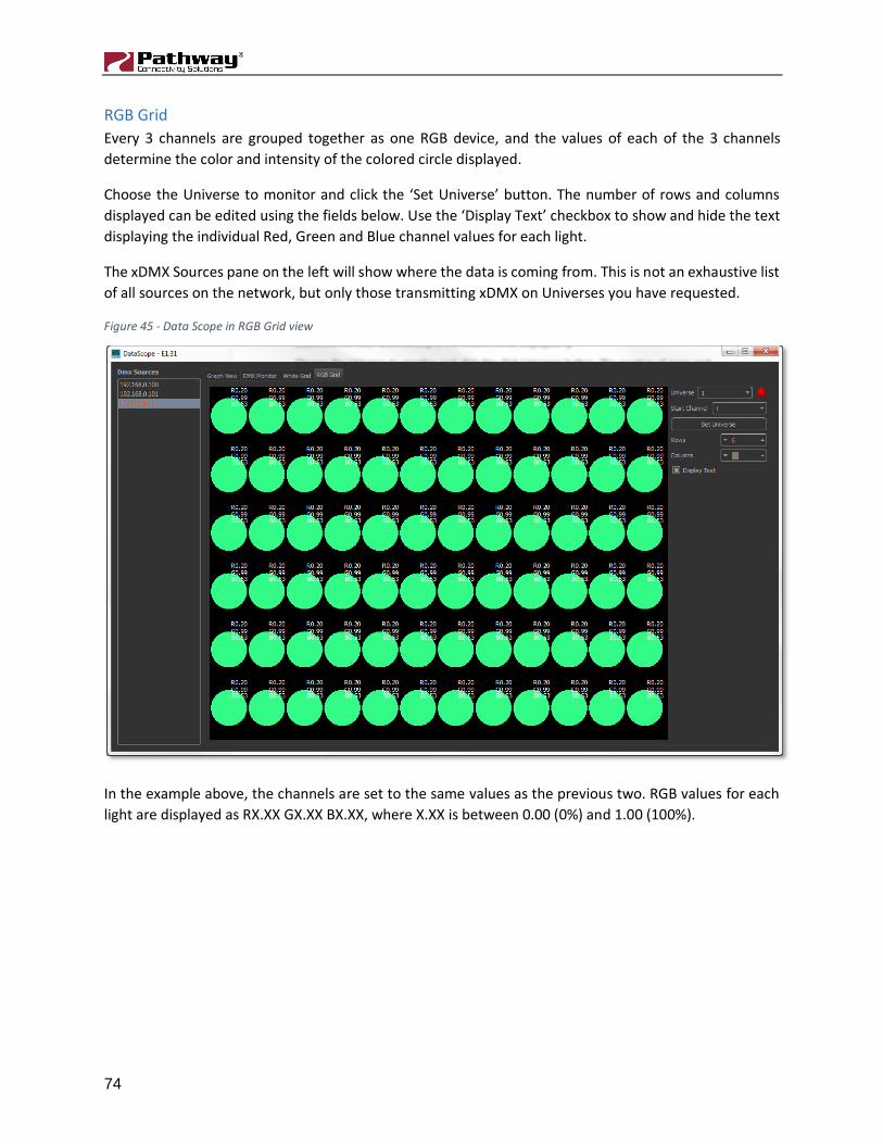
74
RGB Grid
Every 3 channels are grouped together as one RGB device, and the values of each of the 3 channels
determine the color and intensity of the colored circle displayed.
Choose the Universe to monitor and click the ‘Set Universe’ button. The number of rows and columns
displayed can be edited using the fields below. Use the ‘Display Text’ checkbox to show and hide the text
displaying the individual Red, Green and Blue channel values for each light.
The xDMX Sources pane on the left will show where the data is coming from. This is not an exhaustive list
of all sources on the network, but only those transmitting xDMX on Universes you have requested.
Figure 45 - Data Scope in RGB Grid view
In the example above, the channels are set to the same values as the previous two. RGB values for each
light are displayed as RX.XX GX.XX BX.XX, where X.XX is between 0.00 (0%) and 1.00 (100%).
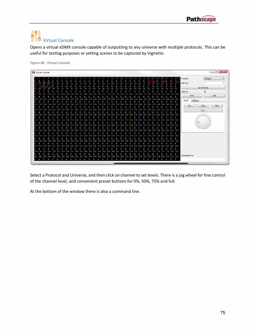
75
Virtual Console
Opens a virtual xDMX console capable of outputting to any universe with multiple protocols. This can be
useful for testing purposes or setting scenes to be captured by Vignette.
Figure 46 - Virtual Console
Select a Protocol and Universe, and then click on channel to set levels. There is a jog wheel for fine control
of the channel level, and convenient preset buttons for 0%, 50%, 75% and full.
At the bottom of the window there is also a command line.

76
Settings Menu
Network Interfaces
This menu option will bring up a dialog which will allow you to enable or disable the network interfaces
connected to Pathscape. Simply click on the checkbox in the Enabled column to change the setting. By
clicking OK, you will close the dialog and all devices will be rediscovered on the currently enabled network
interfaces. If you use your computers settings to change the network interfaces’ IP address, you should
restart Pathscape to re-populate this list.
Figure 47 - Network Interfaces
Show Button Text
By default, each Toolbar icon has descriptive text underneath it. Uncheck this menu item to remove the
text and shrink the toolbar to a more compact size.
Window Menu
Properties
Show or hide the Properties dock-able window using this command.
Message Viewer
Show or hide the Message Viewer dock-able window.
Transaction Editor
Show or hide the Transaction Editor.
Toolbar
Show or hide the Toolbar.

77
Open All
Shows all three dock-able windows (Properties, Message Viewer, and Transaction Editor).
Close All
Hides all three dock-able windows (Properties, Message Viewer, and Transaction Editor).

78
Help Menu
Manual
Opens the PDF Manual.
What’s This?
Click on this menu command, then move the mouse over any of the controls in the program. As long as
the pointer has a question mark (?) next to the arrow, you can click on that control to get a pop-up tooltip
with more information on the selected item.
Technical Help
Opens a dialog with contact information for Pathway Connectivity’s technical support.
Send System Logs
Selecting this command will bring up a dialog which will allow you to send system log files to Pathway
Connectivity support. During use, Pathscape stores system log information as you configure your network
and these logs can then be seamlessly sent to Pathway Connectivity for debugging purposes if you require
support.
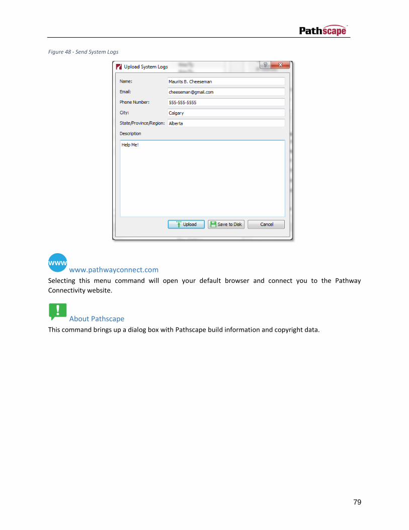
79
Figure 48 - Send System Logs
www.pathwayconnect.com
Selecting this menu command will open your default browser and connect you to the Pathway
Connectivity website.
About Pathscape
This command brings up a dialog box with Pathscape build information and copyright data.

80
RDM Device View
Screen Layout and Navigation
Figure 49 - Main Tool Bar (RDM Device View)
RDM Device view is a mode where configuration and monitoring of RDM devices connected to Pathway
gateways is possible.
The RDM Device View contains one main device tree window and three dockable windows. The Device
Details, Sensor Readings, and Message Log windows are all dockable windows which can be moved out
of the main program window or closed. Dockable windows can be moved by clicking and dragging on the
title bar of the window that you wish to move. Drop the dockable window within the main window to re-
dock the window, or outside of the main window to float the window.
Dockable windows can be dropped anywhere within the main window, and also on top of other dockable
windows to create a tabbed set of views. Dockable windows cannot, however, be dropped on top of the
main device tree view.
Under the Window menu at the top of the main screen, you can also show or hide any of the dockable
windows.
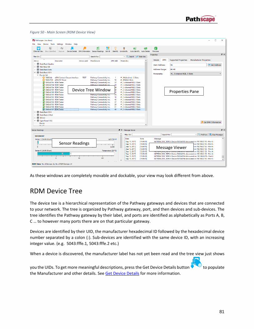
81
Figure 50 - Main Screen (RDM Device View)
As these windows are completely movable and dockable, your view may look different from above.
RDM Device Tree
The device tee is a hierarchical representation of the Pathway gateways and devices that are connected
to your network. The tree is organized by Pathway gateway, port, and then devices and sub-devices. The
tree identifies the Pathway gateway by their label, and ports are identified as alphabetically as Ports A, B,
C … to however many ports there are on that particular gateway.
Devices are identified by their UID, the manufacturer hexadecimal ID followed by the hexadecimal device
number separated by a colon (:). Sub-devices are identified with the same device ID, with an increasing
integer value. (e.g. 5043:fffe.1, 5043:fffe.2 etc.)
When a device is discovered, the manufacturer label has not yet been read and the tree view just shows
you the UIDs. To get more meaningful descriptions, press the Get Device Details button to populate
the Manufacturer and other details. See Get Device Details for more information.
Device Tree Window Properties Pane
Sensor Readings Message Viewer

82
Figure 51 - RDM Device Tree
Other information shown in the device tree includes the device name (Name - if it is supported by the
device’s manufactuer in their RDM implimentation), the current DMX address (DMX Addr) for the device
if applicable, and the number of channels (No. of Channels) for the device using the current personality
(see Device Details - DMX).
Multiple devices can be selected (highlighted) in this tree using standard click and shift+click operations.
The device information shown in the Device Details and other windows will vary, depending on the
information and the number of devices selected.
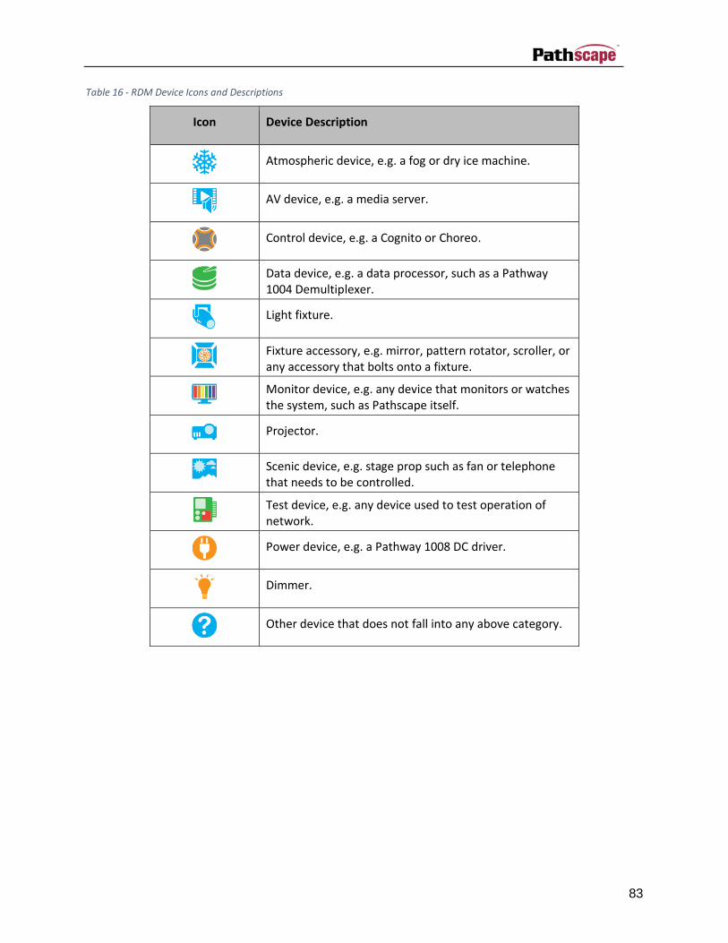
83
Table 16 - RDM Device Icons and Descriptions
Icon Device Description
Atmospheric device, e.g. a fog or dry ice machine.
AV device, e.g. a media server.
Control device, e.g. a Cognito or Choreo.
Data device, e.g. a data processor, such as a Pathway 1004 Demultiplexer.
Light fixture.
Fixture accessory, e.g. mirror, pattern rotator, scroller, or any accessory that bolts onto a fixture.
Monitor device, e.g. any device that monitors or watches the system, such as Pathscape itself.
Projector.
Scenic device, e.g. stage prop such as fan or telephone that needs to be controlled.
Test device, e.g. any device used to test operation of network.
Power device, e.g. a Pathway 1008 DC driver.
Dimmer.
Other device that does not fall into any above category.
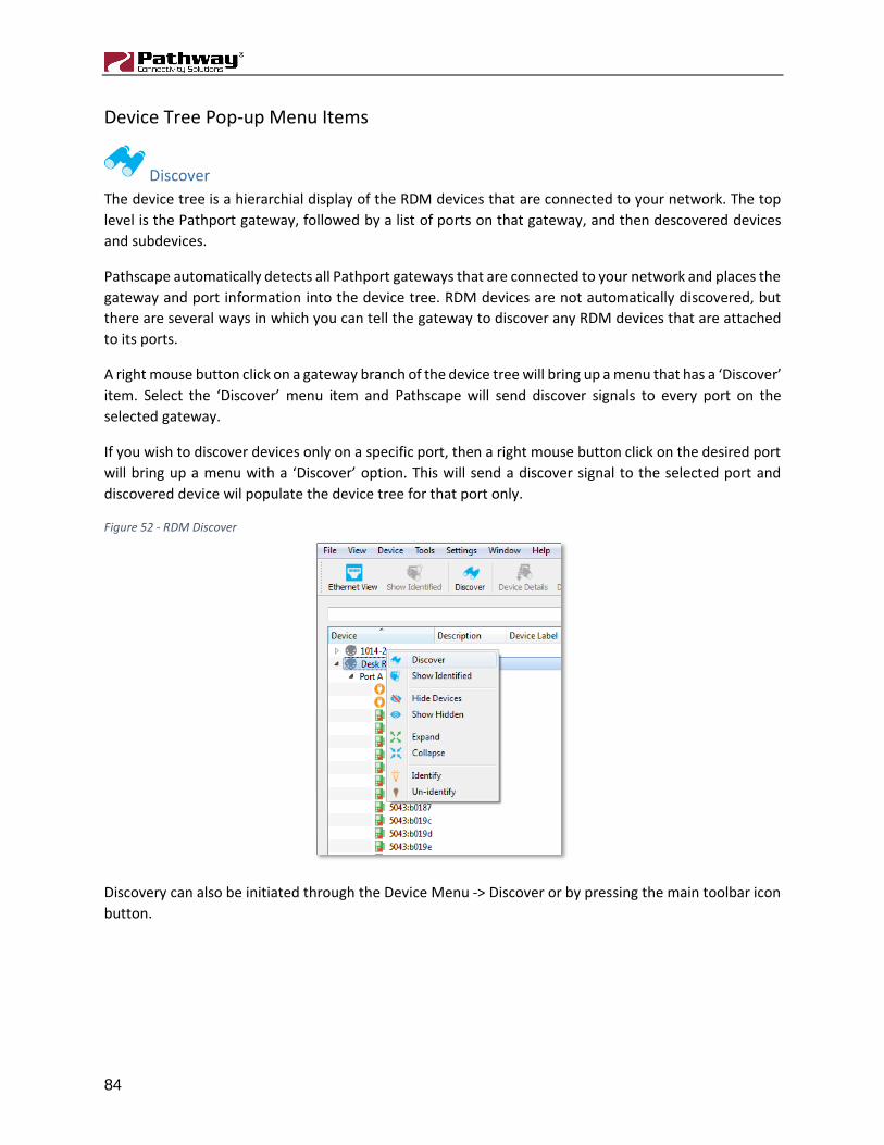
84
Device Tree Pop-up Menu Items
Discover
The device tree is a hierarchial display of the RDM devices that are connected to your network. The top
level is the Pathport gateway, followed by a list of ports on that gateway, and then descovered devices
and subdevices.
Pathscape automatically detects all Pathport gateways that are connected to your network and places the
gateway and port information into the device tree. RDM devices are not automatically discovered, but
there are several ways in which you can tell the gateway to discover any RDM devices that are attached
to its ports.
A right mouse button click on a gateway branch of the device tree will bring up a menu that has a ‘Discover’
item. Select the ‘Discover’ menu item and Pathscape will send discover signals to every port on the
selected gateway.
If you wish to discover devices only on a specific port, then a right mouse button click on the desired port
will bring up a menu with a ‘Discover’ option. This will send a discover signal to the selected port and
discovered device wil populate the device tree for that port only.
Figure 52 - RDM Discover
Discovery can also be initiated through the Device Menu -> Discover or by pressing the main toolbar icon
button.

85
Identify
Once a port has been populated with devices, new menu items will be available in the right mouse button
menu for gateways, ports, and devices. If you right-click on a gateway, ‘Identify’ and ‘Un-identify’ are
selectable. From this menu, ‘Identify’ will send an identify signal to every device on every port. ‘Un-
identify’ will send an un-identify signal to each device. The ‘Identify’ and ‘Un-identify’ menu options from
a port will send the signals to all the devices on just the selected port. If you right-click on the device, then
the identify signal will only be sent to that one device.
‘Show Identified Devices’ (available only on the ports’ right-click menau) will poll all the devices on that
port for the identify flag, and if the identify flag is set for an RDM device, the device tree will indicate
which devices on that port are in identify mode by highlighting the identified devices with a background
color on the device tree.
Figure 53 - Show Identified Devices
You can also identify a device by using the main menu option View->Identify Device or by selecting the
main toolbar icon button .

86
Figure 54 - Devices in Identified Mode
Un-identify
To set the identify mode for a device to off, select the ‘Un-identify’ menu option. This will return the
device branch item to its normal text color, and the icon will return to the device’s default icon.
You can also un-indentify a device by using the Device Menu->Un-identify Device or by selecting the main
toolbar icon button .
Device Information
A right-click on a device shows a few new options, depending on what type of device that has been
selected. All devices will have the ‘Get Device Details’, ‘Get DMX Information’, and the ‘Get All’ menu
options. If the device has sensors, a ‘Get Sensor Readings’ option will be available.
Figure 55 - Device Information

87
Get Device Details
Upon discovery, Pathscape automatically sends a GET request for the required DEVICE_INFO parameter
and the SUPPORTED_PARAMETERS parameter. This is done so that basic information for each device is
available immediately after discovery.
The ‘Get Device Details’ menu option sends several GET RDM commands to the attached port to obtain a
good subset of the device information. This option will first send a get request for:
• The required device info (DEVICE_INFO), followed by:
• Supported parameters (SUPPORTED_PARAMETERS)
• Parameter descriptions (PARAMETER_DESCRIPTION)
• The software version label (SOFTWARE_VERSION_LABEL)
• The device model description (DEVICE_MODEL_DESCRIPTION)
• The manufacturer label (MANUFACTURER_LABEL)
• The product detail id list (PRODUCT_DETAIL_ID_LIST), and finally:
• The device label (DEVICE_LABEL)
Pathscape will send these GET requests to the selected device on the port and populate the Device Details
window with the returned information. Any errors encountered by the RDM GET requests are reported
in the Message Log in red text.
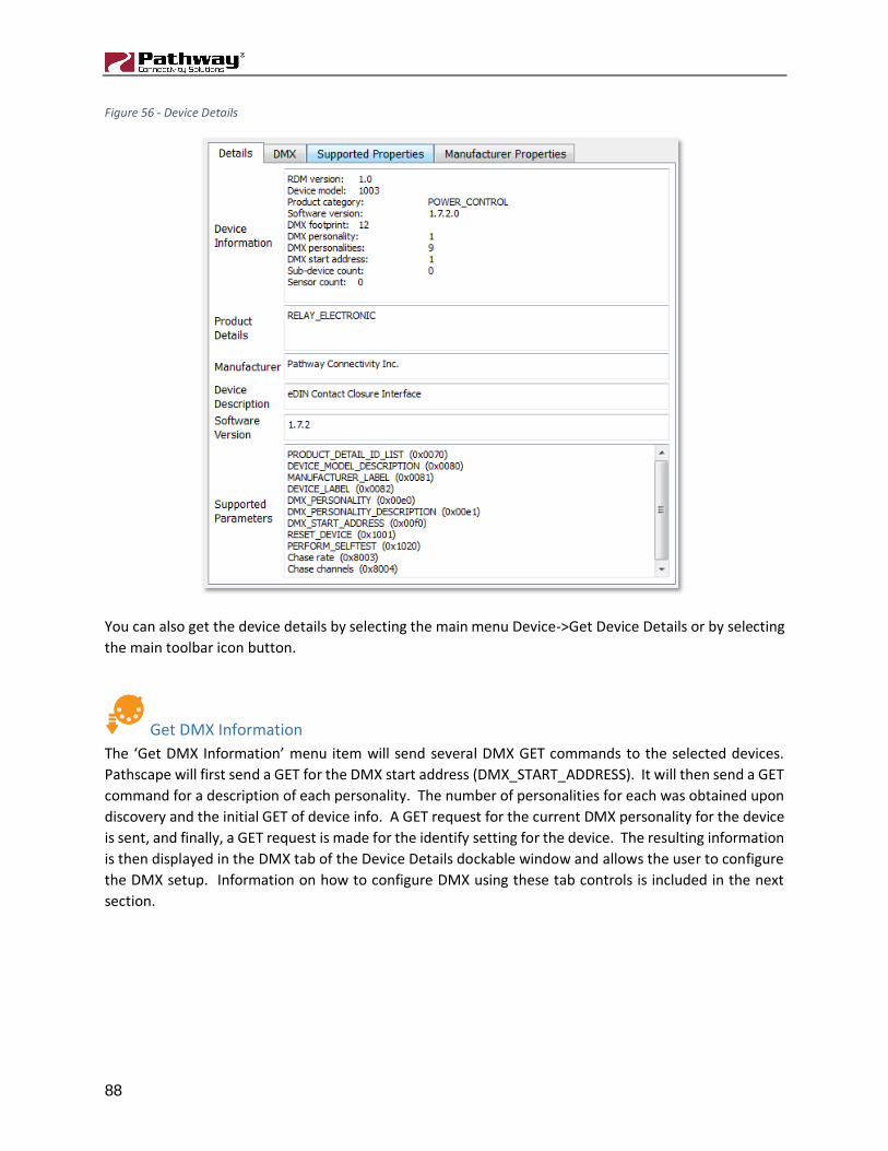
88
Figure 56 - Device Details
You can also get the device details by selecting the main menu Device->Get Device Details or by selecting
the main toolbar icon button.
Get DMX Information
The ‘Get DMX Information’ menu item will send several DMX GET commands to the selected devices.
Pathscape will first send a GET for the DMX start address (DMX_START_ADDRESS). It will then send a GET
command for a description of each personality. The number of personalities for each was obtained upon
discovery and the initial GET of device info. A GET request for the current DMX personality for the device
is sent, and finally, a GET request is made for the identify setting for the device. The resulting information
is then displayed in the DMX tab of the Device Details dockable window and allows the user to configure
the DMX setup. Information on how to configure DMX using these tab controls is included in the next
section.

89
Figure 57 - DMX Information
DMX information can also be read by using the main menu Device->Get DMX Information menu item or
by touching the main toolbar icon button.

90
Get Sensor Readings
When this menu item is selected for one or more devices, Pathscape will send GET requests for the
readings of each sensor in the device. As replies are received from the devices, the sensor values are
displayed in the Sensor Readings dockable window.
The Sensor Readings window shows the reading for each device as shown below. The device ID is used as
a header, and each sensor is represented by gauge which shows the sensor label along with the units. The
arrows within the gauge indicate the optimum minimum and maximum operating range as defined by the
device. When the current reading is within the optimum ranges, the gauge color is blue, when the current
value falls outside the range, the gauge color is red.
Figure 58 - Sensor Readings
Sensor readings can also be obtained by using Device Menu->Get Sensor Readings or by clicking the main
toolbar icon button.

91
Get All (Device, DMX, Sensor)
The ‘Get All (Device, DMX, Sensor)’ menu item simply combines the previous three menu items into one.
Essentially, this menu item just makes the same GET requests as the individual ‘Get Device Details’, ‘Get
DMX Information’, and ‘Get Sensor Readings’ menu items. If the device does not contain any sensors,
then the sensor readings requests are ignored.

92
RDM Device Details Window
Details
The Details tab of the Device Details window is information only tab which shows the details of the device
or devices that are selected in the device tree. The first box in this tab displays the Device Information,
which was acquired from the device using the required DEVICE_INFO parameter from the RDM ANSI E1.20
– 2010 definition.
This information includes the device model, product category, software version, DMX footprint, DMX
personality, DMX personalities, DMX start address, Sub-device count, and sensor count.
Figure 59 - Device Details
Other information includes the Product Details, the Manufacturer, Device Description, Software Version
and the Supported Parameters.
There are three ways in which you can get all the information displayed in this tab. First, you can use the
right mouse button click pop-up menu on a device and select the menu item ‘Get Device Details’. Another
way is to use the Device Menu->Get Device Details option, or lastly, you can click the main toolbar icon
button to get the device information for this tab display.

93
Once the detail information has been requested from a device, each time that device is selected in the
device tree, the information specific to that selected device will be displayed in this tab. You may need to
re-Get the information to ensure it’s not stale; for example, if you’re monitoring temperature, you want
to make sure you’re not looking at the temperature from the last Get.
Supported PIDs
This tab contains a table of the parameters that are supported by the device as defined by the parameter
SUPPORTED_PARAMETER. This list is populated when a ‘Get Device Details’ option is used. In this table,
you can select any of the supported parameters and initiate a GET or SET request, depending on the type
of parameter. A list of all supported parameters and their allowable settings can be found in the ANSI
E1.20 – 2010 RDM documentation.
Most of the supported parameters are simple GETs and SETs using a single value and are self- explanatory,
but due to the nature of the structure of some parameters, a description of the mechanisms of how to do
a GET or SET on a selection of supported parameters will be included.
To get the supported parameter value from the majority of the selections, all you have to do is highlight
the desired parameter in the table and depending on the parameter, the ‘Get Selected’ or ‘Set’ buttons
will be enabled. If the supported parameter is not settable, then the Set button will remain disabled.
You can also send a GET request for all supported parameters for all selected devices by pushing the ‘Get
All’ button at the bottom of the tab. Warning: Getting the desired results may take a long time (10’s of
seconds), depending on the number of supported parameters, the type of parameters, and the number
of selected devices.
As of the writing of this document, SET commands are only allowed one parameter at a time. To set a
parameter, double click on the Current Value column of the Supported PID table and type in the value you
want. Then touch the ‘Set’ button and Pathscape will attempt a SET request on the device. Check the
message log for status.

94
Figure 60 - Supported PIDs
DMX Setup
The DMX tab in the Device Details window allows you to get and set DMX data for the selected device. To
set the DMX start address, simply type the integer value you want the DMX addressing to start and press
the ‘Set’ button next to the DMX Start Address edit field.
The DMX Address Range shows the range of DMX address set for the selected device (multiple devices
can also be selected but the DMX configuration that can be done on multiple devices may be limited).
To auto address DMX, type the starting address integer that you want into the Auto Address DMX first
address edit box and press the Auto Address DMX. This will set the DMX addresses for the selected device
based on the personality that is set.
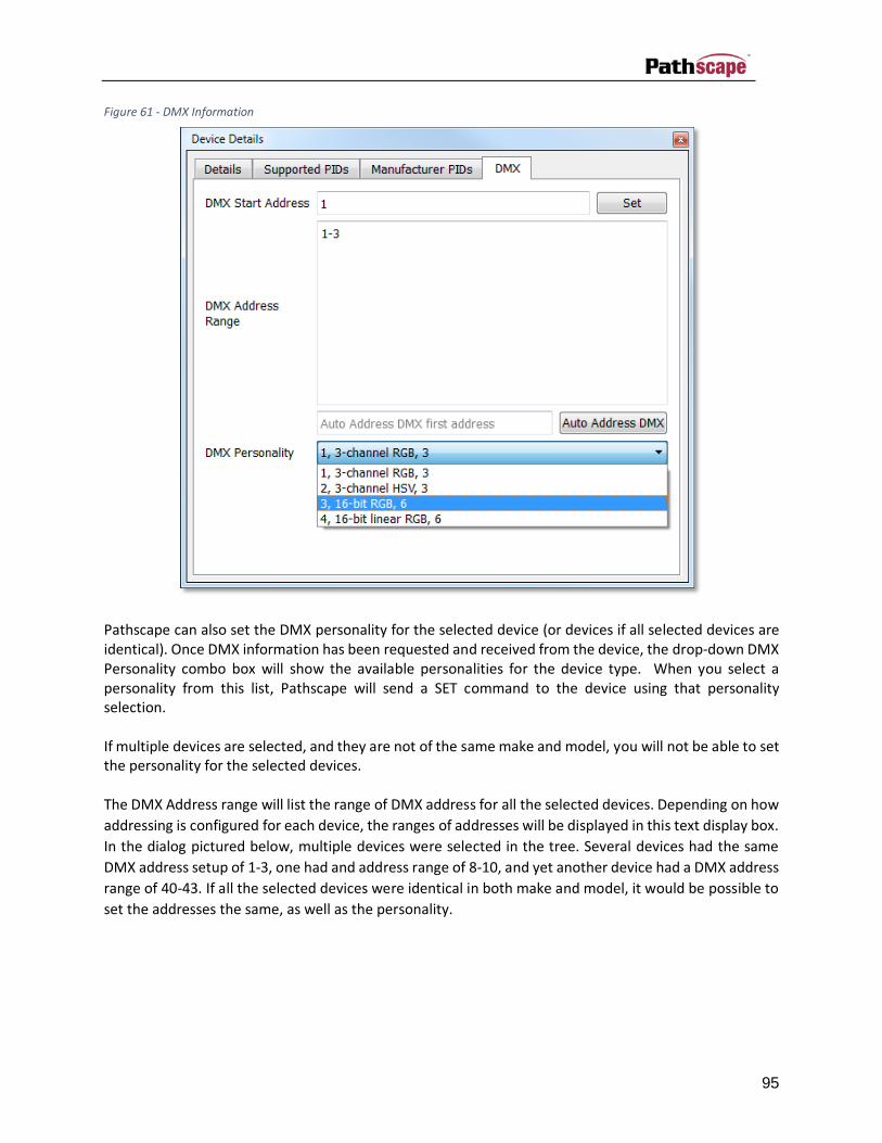
95
Figure 61 - DMX Information
Pathscape can also set the DMX personality for the selected device (or devices if all selected devices are identical). Once DMX information has been requested and received from the device, the drop-down DMX Personality combo box will show the available personalities for the device type. When you select a personality from this list, Pathscape will send a SET command to the device using that personality selection. If multiple devices are selected, and they are not of the same make and model, you will not be able to set the personality for the selected devices. The DMX Address range will list the range of DMX address for all the selected devices. Depending on how
addressing is configured for each device, the ranges of addresses will be displayed in this text display box.
In the dialog pictured below, multiple devices were selected in the tree. Several devices had the same
DMX address setup of 1-3, one had and address range of 8-10, and yet another device had a DMX address
range of 40-43. If all the selected devices were identical in both make and model, it would be possible to
set the addresses the same, as well as the personality.

96
Figure 62 - DMX Information - Multiple Devices

97
Manufacturer PIDs
As per ANSI E1.20, manufacturer specific PIDs can be defined with IDs in the range of 0x8000 to 0xFFDF.
This tab allows the user to display the details of the defined manufacturer PIDs. The PID information is
read when you initiate a ‘Get Device Details’ selection. As of the writing of this document, the ‘Set’ for
manufacturer PIDs has not yet been implemented.
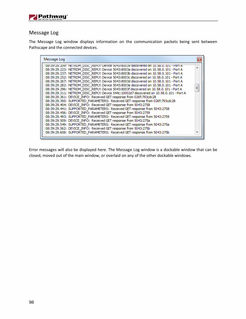
98
Message Log
The Message Log window displays information on the communication packets being sent between
Pathscape and the connected devices.
Error messages will also be displayed here. The Message Log window is a dockable window that can be
closed, moved out of the main window, or overlaid on any of the other dockable windows.

99
RDM View Menus
RDM File Menu
Reconnect Device
If a device that previously showed as ‘Online’ now shows ‘Offline’ (Red light next to its name in the device
tree), this function will attempt to reconnect to the device.
Exit
Exits Pathscape.
View Menu
Ethernet Device View
Switches to Ethernet Device view to see devices connected by Ethernet.
Show Identified Devices
This button is only enabled if a port is selected in the device tree. It will poll all devices attached to that
port and will indicated which devices are in identify mode by changing the device icon on the tree to a
green checkmark, and highlighting the text for the device in red.
Hide Devices
Hides the selected device(s), removing them from the Devices view. The number of hidden subdevices
will be shown in the bottom status bar.
Show Hidden Devices
Shows any device(s) that were previously hidden.
Change Skin
This will change the UI color theme from light grey to dark grey. In low light settings, the darker theme
may be easier on the eyes. Use whichever you prefer. To switch back to the light grey theme, simply select
this from the menu again.

100
Device Menu
Discover
If a node or port is selected in the device tree, this option is available. Otherwise, it will be greyed out.
Will attempt to discover all RDM devices on the selected gateway or port.
Get Device Details
This button will poll the device for the device details as explained in the previous section. Several RDM
GET commands are sent to the selected devices.
Get DMX Information
This button will send several GET commands to the selected devices to get the DMX addressing data.
Get Sensor Readings
Select this button to get the sensor readings, such as lamp hours or temperature from all the selected
devices.
Get All (Device, DMX, Sensor)
Get All (Device, DMX, Sensor) button icon. Select this button to get all the device information will one
click, it will combine the Detail, DMX, and Sensor calls into one button click.
Identify Device
Selecting this button will send a SET identify mode on packet to the selected devices.
Un-Identify Device
Selecting this button will send a SET identify mode off packet to the selected devices.
Settings Menu
Auto Identify
This is a ‘sticky’ button that when set, will automatically send a SET identify packet to the selected devices
and SET off the identify mode on any previously identified devices as devices are selected and deselected
in the device tree.

101
Auto Get Details
This is a ‘sticky’ button that when engaged will automatically send a GET device details commands to the
device as it is selected in the device tree.
Get DMX On Discovery
Check this menu item to automatically Get DMX Information during the Discovery process.
Show Button Text
By default, each Toolbar icon has descriptive text underneath it. Uncheck this menu item to remove the
text and shrink the toolbar to a more compact size.
Window Menu
Properties
Show or hide the Properties dock-able window using this command.
Message Viewer
Show or hide the Message Viewer dock-able window.
Sensor Readings
Show or hide the Sensor Readings dock-able window.
Toolbar
Show or hide the Toolbar.
Open All
Shows all three dock-able windows (Properties, Message Viewer, and Sensor Readings).
Close All
Hides all three dock-able windows (Properties, Message Viewer, and Transaction Editor).

102
Appendix 1: VIA Ethernet Switch Default Settings
The following settings reflect the current firmware (v 3.9.0) for all VIA switch models.
Table 17 - VIA Default Settings
Factory Default Settings
IP Address Static - 10.x.x.x - based on serial number
Subnet mask 255.0.0.0
Default Gateway 10.0.0.1
VLANs Disabled (all ports untagged using VLAN ID#1)
Mgmt VLAN ID# 1
QoS (Quality of Service)
Disabled
IGMP Filtering Disabled
DHCP Disabled
Art-Net to sACN Conversion
Disabled
Alternate Art-Net Mapping
Enabled (depends on above item being enabled)
Port Link Auto-negotiate
Ring Protect Disabled
PoE Supply 60W internal supply – model 6730
0W – External Supply Value – all other models (PoE effectively disabled)
Port PoE Enabled (requires sufficient available PoE supply)

103
Appendix 2: Virtual Local Area Network (VLAN)
A VLAN (Virtual Local Area Network) is a group of ports on the switch (or switches) that are configured to
pass traffic to one another, but not to ports on any other VLAN. When VLANs are established, ports that
connect switches to switches must be tagged to pass all VLAN traffic.
This feature allows the user to arrange lighting consoles, gateways and other network gear into groups of
equipment. The usual purpose is to minimize unnecessary traffic to the equipment, or to segregate
different types of equipment (lighting, audio, video) so that the network subnet setups do not collide and
the local networks do not get flooded with irrelevant data.
Definitions
Normal/Untagged ports belong to a specific VLAN as configured by the user, and will only pass traffic that
belongs to that VLAN. These ports are typically connected to end devices.
Uplink/Tagged ports pass all network traffic with VLAN ‘tags’ within the VLAN range established for that
switch (see Range Configuration below). Typically, you would use tagged ports to connect switches
together.
Tag refers to the marker added to (or removed from) the data packet as the packet enters or exits from a
Normal/Untagged port on the switch. The “Tag” determines which VLAN the data packet is assigned to.
Management VLAN refers to the VLAN that the switch’s management processor is assigned to use. Care
must be taken that the Management VLAN is used by at least one Normal/Untagged port on the switch,
or the ability to configure the switch may be lost. It is strongly recommended that the Management VLAN
be identical to the VLAN Range Start value.
VLAN ID (ID#) is assigned to Normal/Untagged ports and determines which VLAN that port operates
within.
A Normal/Untagged port may only be associated with one VLAN ID# at a given time.
When using software to configure the switch, make sure your computer is connected to a Normal
(Untagged) port set to the same VLAN ID# as used by the management processor. Failure to do so will
prevent configuration from being applied.
VLAN Guidelines
Plan the VLAN layout first. The creation of a map of the network, showing which devices to associate with
which VLAN, is strongly recommended prior to configuration.
Generally speaking, ports connected to end devices will be configured as Normal/Untagged and given a
VLAN ID#.

104
Ports connected to other VIA switches will typically be set as Uplink/Tagged, so multiple VLANs may be
forwarded between switches, or when a VLAN must be forwarded through an intermediate switch (where
that VLAN is not in use) on to a third switch beyond. It is possible to set the ports that connects to another
switch as Normal/Untagged, and given a VLAN ID#, in cases where it’s desirable to pass only one VLAN to
downstream switches.
When configuring VLANs, remember that each switch must be uniquely identified on each VLAN in use on
that switch. By default, only the management VLAN is automatically assigned an IP and subnet mask. All
other VLANs default to a null IP address value (0.0.0.0). Use the Network Configuration options available
from the VLAN configuration screen to configure the desired IP settings for each VLAN.
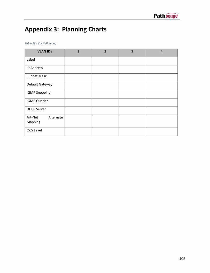
105
Appendix 3: Planning Charts
Table 18 - VLAN Planning
VLAN ID# 1 2 3 4
Label
IP Address
Subnet Mask
Default Gateway
IGMP Snooping
IGMP Querier
DHCP Server
Art-Net Alternate Mapping
QoS Level

106
Switch Label:
Base IP: Subnet: Gateway:
QoS (Off/Standard/Dante):
VLAN (Enable/Disable): Range: Mgmt ID#:
Art-Net Alternate Mapping (On/Off – on is default):
PoE External Supply Present: External Supply Size (in W):
Port 1 2 3 4 5 6 7 8 9 10 11 12 13 14
Connected Device
Normal/Uplink
VLAN ID#
ArtNet to sACN
PoE Max
Link Mode
SFP Type

107
Appendix 4: EAPS & RSTP – “Ring Protection”
Ethernet wiring schemes are based on a ‘star’-wiring topology. Ring (or loop) data wiring – where the last
device in a chain is wired back to the first device without RSTP or EAPS setup will quickly ‘break’ your
network. Only one data path between any two devices is allowed.
Pure star-wiring layouts leave your network prone to a single point of failure. Unlike DMX512 networks,
passive data ‘thru’ connections are not possible with Ethernet. A severed cable or power loss to a switch
can mean the loss of some or even all show control.
Ring Protection allows the deliberate – and designed – use of a ring wiring system for Ethernet
communications. With EAPS or RSTP enabled, VIA switches ignore data traffic on one segment of the ring,
while monitoring the integrity of the remaining connections. If an interruption is detected, the unused
ring segment is activated and full communication is restored.
Ethernet Automatic Protection Switching (EAPS) uses dedicated tagged ports whereas Rapid Spanning
Tree Protocol (RSTP) can use any two ports on a switch. Fail-over time when using EAPS on dedicated
ports is between 50 and 75 milliseconds, or two to four DMX packets. Using RSTP, the healing process can
take a second or two.
Requirements and Limitations
VLANs must be enabled to use Ring Protection. EAPS uses a dedicated VLAN to monitor the integrity of
the ring. By default, VLAN 4095 is used. The Ring Protection VLAN must be outside of the established
VLAN range.
Only ports 11 through 14 on models 6740, 6741 and 6742, and ports 9, 10 and 11 on model 6730 may be
used with this feature. This feature is not supported by the 6705 or 6706 VIA5.
EAPS works with Pathport VIA switches only. Switches from other manufacturers can co-exist on the
network, but should not be placed in-line with the ring.
Definitions for EAPS
Master switch monitors the integrity of communications. Only one switch on the network may be
configured as the master.
Transit switches receive and forward the ring monitoring packets. All switches other than the Master must
be set as transit switches.
Primary port is the main (active) UPLINK connection link on the Master switch, joining to the rest of the
network. All transit switches must also have one port configured as the primary. Only ports 11 through 14
are available to be used as the primary port.

108
Secondary port is an UPLINK port ‘ignored’ (logically blocked) by the Master switch to break the ring
topology. All transit switches also must have one port configured as the secondary port. The secondary
port is actively used on transit switches. Only ports 11 through 14 are available to be used as the secondary
port.
Control VLAN is a unique VLAN ID dedicated to monitoring the health of the network. All switches must
use the same control VLAN. The default is VLAN ID 4095.
Note: Ring Protection wiring topology is not structured. Primary ports can be connected to either the
Primary or Secondary port on the next VIA.
Software Configuration of Ring:
• Start with the redundant wiring segment unplugged.
• Connect the computer running Pathscape to one of the end switches, in the wiring chain.
• Configure the switch that is physically furthest away on the chain. Work backwards until reaching
the closest switch.
• Now plug in the redundant wiring segment. Check the message on the LCD of the switch, which
should change within a few seconds from “Ring Protect State: Failed” to Ring Protect State:
Complete”.
• If the “Failed” message does not clear, unplug the redundant segment and check the port settings
of each switch for misconfiguration.

109
Index
A
all off · 42
allow record · 35, 41
arrows · 23
Art-Net alternate mapping · 49, 56
Art-Net trap and convert · 52
Art-Net trap-and-convert · 49
astronomical · 42
astronomical events · 42
auto address DMX · 94
auto identify · 100
B
background discovery · 58
backlight · 55
bandwidth meter · 52
blackout zones button · 41
bring to front · 23
C
changing properties · 9
channel patch · 22
clock · 42
clock enable · 43
copy · 68
crossfade · 57
D
Dante · 49
Data Scope · 71
dead black out · 42
default look · 36
device notes · 16
device tee · 81
devices tab · 9
DHCP · 3
DHCP server · 54
discover · 100
DMX monitor · 72
DMX personality · 95
DMX triggers · 33
DMX512 port properties · 56
DNS server · 42
dock-able panes · 6
E
E1.31 sACN priority · 58
EAPS · 49, 107
emergency output priority · 42
Ethernet Device Properties · 47
ethernet device view · 4
ethernet port properties · 51
exclusive lock · 41
external PoE supply · 50
F
factory default · 70
factory reset · 9
file menu · 67
filter · 65
firewall exception · 2
firmware · 70
fit to view · 26
forwarding state · 51
front panel lockout · 55
full duplex · 51
function start channel · 35
G
get device details · 81
get RDM device details · 87
goto inactive · 41
grandmaster · 40
H
half duplex · 51
help menu · 78
hiding devices · 10
high output priority · 42
HTP · 22, 29
I
identify · 68, 86
IGMP querier · 54

110
IGMP snooping · 54
inactive snapshot · 36
input port · 22
input priority · 56
installer · 2
IP gateway · 42
IP settings · 3
IPv4 · 55
L
latitude · 43
LLDP partner · 51
load show · 67
location · 42
lockout: listen for universe · 33
longitude · 43
M
MAC address · 48
management VLAN · 49
manufacturer PIDs · 97
master output level · 40
maximum light level · 40
merged · 29
message log · 98
message viewer · 65
minimum light level · 40
N
network interfaces · 3, 76
Network Sliders and Buttons · 59
NIC · 3
normal output priority · 33, 42
NSB · 59
NTP server · 42
number of universes · 32
O
online devices · 11
output port · 22
override output priority · 33, 42
P
paste · 69
patch grid · 28
patch items · 22
patch map · 21
patch name · 57
patching with RDM · 94
Pathport gateway properties · 55
per channel priority · 57
personality · 95
PIDs · 93
ping ponging · 36
playback · 36
PoE · 16
PoE status color codes · 17
port group · 22
power over ethernet · 16
power tab · 17
press-and-hold to record · 41
priority · 22, 30
Priority Override · 42
properties message viewer · 7
properties pane · 47
Q
QoS · 49
quality of service · 49
R
radio-toggles button · 36
Rapid Spanning Tree Protocol · 50
RDM · 67
RDM background discovery · 58
RDM device icons · 83
RDM Device View · 4, 80
RDM discovery · 84
RDM identify · 85
reboot · 69
reconnect device · 99
record allowed · 41
Record Now · 36
rediscover · 68
release all · 42
remote control of Vignette · 33
RGB grid · 74
ring protect · 49
ring protection · 107
RSTP · 50, 107

111
S
sACN sense · 33
safety light level · 40
save show · 67
search · 65
send system log · 78
send to back · 23
sensor readings · 90
set DMX · 94
settings menu · 76
SFP · 51
show button text · 101
show file · 67
show mode · 33, 41
Shownet · 56
signal loss · 57
skin · 68, 99
snapshot management · 38
snapshot start channel · 34
snapshots · 37
sorted · 9
start universe · 32
startup snapshot · 36
subdevices · 11
subnet mask · 3
sunrise · 42
supported RDM PIDs · 93
switch port icon colors · 15
switch properties · 48
sync system time · 42
system log · 78
system time zone · 42
T
tagged · 52, 103
tagged ports · 103
take control · 41
toolbar · 7
transaction · 47
transaction editor · 64
transaction monitor · 7
transit · 107
transmit protocol · 56
triggers · 33
U
UID · 81
undo · 64
un-docked · 5
universe · 22
untagged · 103
upling · 52
uplink · 107
Using Pathscape to record Snapshots · 37
V
Via default properties · 102
view menu · 67
Vignette · 31, 59
Vignette Clock · 42
Vignette playback · 31, 36
Vignette playback properties · 32
Vignette remote control · 33
Vignette zones · 39
virtual console · 75
Virtual Local Area Network · 103
VLAN · 19, 103
VLAN patch · 20
VLAN pool · 20
VLAN properties · 53
VLAN services · 53
W
WiFi NICs · 3
window menu · 76
Z
zone editing · 39
zone start channel · 34