user guide of enormous modeling v2.2.0
TRANSCRIPT

1
User guide of enormous modeling
1 Quick look
1.1 Introduction
1.1.1 About enormous modeling
In the process of modeling, due to the limitation of hardware and software aspects, the
resolution and size of the model are contradictory. To build a high-resolution model, the size of
the model must be limited, and vice versa. Enormous modeling platform is developed to solve
this difficulty. It makes the model without resolution and scale limitation. Any resolution and
any scale model can be built in the Enormous modeling platform.
1.1.2 Features
Enormous modeling guarantees the consistence of the geological structure everywhere in the
entire studied region. It allows multiuser to work simultaneously and performs good
collaboration. The core, innovative seamless structural modeling technologies makes it true to
build a large-scale, high-resolution and consistent model.
Main functions:
1) Mass data storage and management
Well, seismic and geological data
2) Model management and maintenance
Multiple models with different resolutions
Instant local update
Integration with different models
3) Applications
Overview and standard mapping

2
Basic model for other systems
Statistical calculation: volumetric and NTG etc
Professional application: reservoir simulation and injection-production pattern adjustment
1.1.3 Advantage
Integrated data management
Unified model storage
Distributed modeling
---each person works in individual sub region simultaneously ;
---able to consistent /seamless local update
1.1.4 Composition
The Enormous modeling platform consists of seismic surveys and models. A project can
manage multiple seismic surveys and models.
Fig. 1-1 Interface.

3
Data and models managed in the platform are shown below.
Fig. 1-2 Data and models in the platform.
1.2 Module relationships
Enormous modeling platform is an integrated management platform of data and models. It
does not provide modeling functions except seamless model building technologies. The
relevant modules include Structural modeling, Velocity and attribute modeling, Reservoir
geological modeling and Profiles & plan.
Fig. 1-3 Module relationships

4
Structural modeling, Velocity and attribute modeling and Reservoir geological modeling
provide modeling functions for Enormous modeling platform. Download local model data
from the platform and load them to the corresponding modeling module. Finally upload the
finished local model to the platform to be embedded seamlessly and stored.
Based on the enormous model in the platform, maps and profiles can be generated
automatically and efficiently. They are shown in Profiles & plan module.
1.3 Theory
Any resolution and any scale model can be built in the Enormous modeling platform because
firstly the storage mode of model results is different in the platform from the traditional
modeling. The storage mode of model generally is that one model is one file. The models we built
in other modeling module are all stored in this mode. The platform stores models in the mode of
tables and fields and it is the basis of seamless splicing of local models. Then before modeling,
set the cell partition mode which is called fragment. Model splits in fragments through some
process. In the database, the information of each fragment is recorded in the form of field to
save in the table.
1.4 Workflow
Enormous modeling also integrates the modeling process from structural modeling to
reservoir geology modeling. The Enormous modeling platform manages and stores these
models. Other models are based on structural model. So the general modeling order is
structural model in time domain, velocity model, structural model in depth domain and
reservoir geological model.
Before modeling in time domain, seismic survey should be set firstly. The datum is in Seismic
survey setting and it is a necessary parameter for time-depth conversion. Well T-D and
seismic interpretation data can be imported into the seismic survey. The seismic interpretation
data can be extracted into the model in Models.

5
Fig. 1-4 Seismic survey setting.
A new original structural model should be built firstly, and it has two domain types: time and
domain. To build a original model is to set basic parameters and initial conditions. Then
import or extract model data into the original model to build it.
Velocity or reservoir model must be built in the same domain in which structural model is.
Whatever type of the model is, the workflow is almost the same. Structural model will be
taken as an example to illustrate the workflow of enormous modeling.
Fig. 1-5 Workflow
1.4.1 New model
Right-click Models and select New model. Set model parameters in the pop-up window as
shown below. The important parameters are domain type, model coordinates and grid size.
The seismic survey can be selected from existing seismic surveys of the same domain in

6
Seismic surveys or be empty.
Fig. 1-6 New model setting.
Models with different coordinates can be built under the same Models node, but they are
limited in the project area.
Model data can be imported from external data files or extracted from the relevant seismic
survey.
1.4.2 Download local data
Select any sub region as work area within the range of the model, and download the local
model data to be modeled in Structural modeling module.
Fig. 1-7 Work area.
7
Irrelevant local model data can be downloaded at the same time by different users.
1.4.3 Modeling
Load the model data in 3D modeling and build the local model. Modeling workflow can be
found in the user guide of Structural modeling. After finishing the model, model data and
grids can be exported from the 3D modeling.
1.4.4 Upload the model
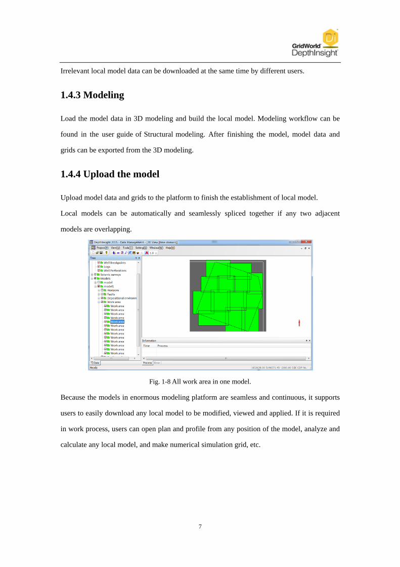
Upload model data and grids to the platform to finish the establishment of local model.
Local models can be automatically and seamlessly spliced together if any two adjacent
models are overlapping.
Fig. 1-8 All work area in one model.
Because the models in enormous modeling platform are seamless and continuous, it supports
users to easily download any local model to be modified, viewed and applied. If it is required
in work process, users can open plan and profile from any position of the model, analyze and
calculate any local model, and make numerical simulation grid, etc.

8
2 How to build enormous model
Please refer to the teaching videos of the enormous modeling platform.
3 Special topic
3.1 Saving mode of Enormous modeling platform
Enormous modeling platform is built on the MySQL database. Compared with the traditional
modeling, the main difference is reflected in the storage mode of model results. Enormous
modeling platform breaks through the traditional modeling in the storage form of independent
model file. It stores models in the mode of tables and fields and uses fragment in it. It is the core
of Enormous modeling. Comparison of traditional modeling and Enormous modeling is shown
in the following table.
Table 3-1 Comparison of traditional modeling and enormous modeling.
Traditional modeling Enormous modeling
Storage mode Model files Tables and fields in the database
Storage and
expression
Model file independent of
each other;
Independent definition,
storage and expression.
Whole model definition;
Storage in fragments;
Fragment expression in any
combination.
Features
1 The model file size is
restricted and limit the
amount of model data.
2.The modification or update
of the model file must change
the entire file.
3. The entire model is stored
with multiple independent
files. It is only shown in the
form of each file and can't
realize display and
application of entire or any
local model.
1. Don't be limited by the amount of
model data . Support the storage of large
amounts of information.
2.Model inform can be updated at any
time. The storage of fragments makes
updating efficiency.
3.Any combination between fragment
realize display and application of entire
or any local model.

9
3.2 Principle of Enormous modeling
Information in the Enormous modeling platform is saved in the form of tables and fields.
Before modeling, users set the cell partition mode. It is the X, Y direction block size in the new
model setting window. Result is saved to the database file. Each cell which is called fragment
saves in a database table. Information is recorded in the form of fields in the table
Fig. 3-1 Division of the cell.
When local model is downloaded, the corresponding fragments are locked. Download the data
and grid in the local work area and outside area. Edit the data in the local area and model under
the constraint of data and grid of outside area.
Fig. 3-2 Principles for downloading local model.
Model is exported into fragments through some process. In the database, the information of
each fragment is recorded in the form of field to save in the table.

10
Fig. 3-3 Principles for uploading local models.
The process of calling is similar to storing. After extracting locked fragments from the database,
they are combined into a complete model, then loaded into the modeling software to display.
3.3 The Seamless structural model building method
Users can download any local model from the Enormous modeling platform and model in the
modeling software. The model finished are uploaded to the platform and automatically,
seamlessly splicing with the adjacent model. When we continue to create a work area, the new
one should overlap with the adjacent finished one. In this way we can ensure seamless splicing
between adjacent models. And finally in the platform, the model is a seamless entire model
based on all data. The following picture is an instance of model partition.
Fig. 3-4 Model partition.

11
In the modeling process of local model, pay attention to the modeling method of splicing area.
There are three fault modeling methods of splicing area to respectively deal with three
conditions.
1) When the fault does not change (Fig. 3-5 a), the model automatic seamless splicing.
2) When the fault changes but the part of the fault in the adjacent area is not affected (Fig. 3-5
b), the model automatic seamless splicing.
3) If the fault has some change and the part of the fault in the adjacent area has been affected
(Fig. 3-5 c), download another C work area model which contains the fault, and rebuild the
model to realize seamless splicing.
Fig. 3-5 Fault splicing modeling method.
As for horizon modeling in the splicing area, the seamless splicing requires merely consistency
of fault model and horizon data.
3.4 Update of enormous model data
3.4.1 Update of structural model data
Multiple models with different area can be stored in a project. Data of the models can be
different. The data in Enormous modeling can be stored in following three ways.
1) Import from data files in the database

12
(a) (b)
Fig. 3-6 Import data node.
(a)Import horizons node. (b)Import faults node.
2) Extract from seismic survey in the database
(a) (b)
Fig. 3-7 Extract data node
(a)Extract horizons node. (b)Extract faults node.
3) Import the data in the modeling software and upload to the database.
The first and the third way belong to "import the data". The range of influence is the area of data
imported.
13
The second way influences the entire model area. So after starting modeling, the function of
extracting data should be used carefully or never.
No matter which way to update the data, model in the scope of the new data must be updated to
ensure data fusion, the match of model and data and the structural consistency.
3.4.2 Update of well data
Unlike model data, a project has only a set of well data. For one well, just one path can be used
and the only well top or breakpoint can be stored in the same depth.
Although there are editing functions for well data in the well management of database, we do
not edti well data in the process of modeling. If any error is found in the well data, it is
submitted to the professionals to check it.
If there is any update or modification in well data, the well data updated or modified need to
import again. When the well data imported have repeated wells with the original data, the data
retention situations is as follows.
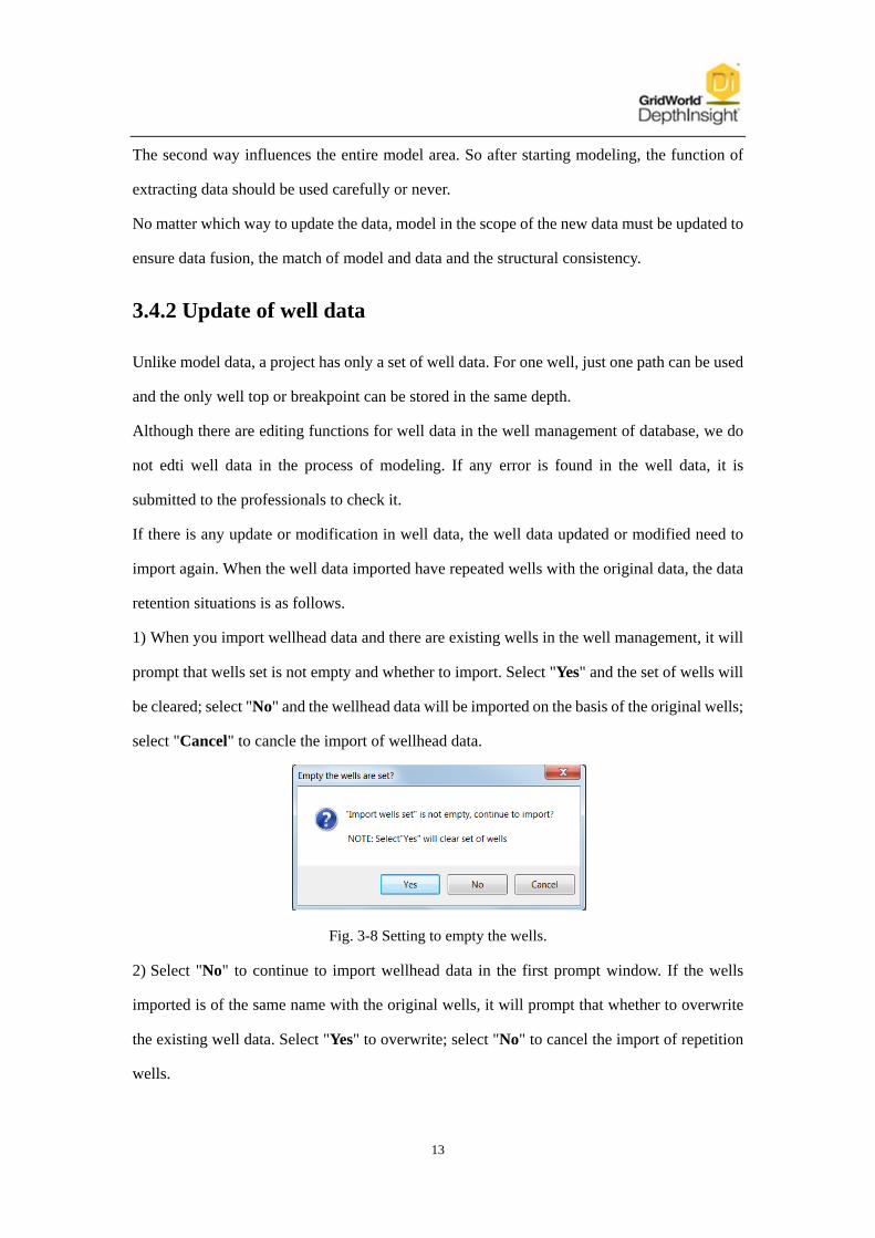
1) When you import wellhead data and there are existing wells in the well management, it will
prompt that wells set is not empty and whether to import. Select "Yes" and the set of wells will
be cleared; select "No" and the wellhead data will be imported on the basis of the original wells;
select "Cancel" to cancle the import of wellhead data.
Fig. 3-8 Setting to empty the wells.
2) Select "No" to continue to import wellhead data in the first prompt window. If the wells
imported is of the same name with the original wells, it will prompt that whether to overwrite
the existing well data. Select "Yes" to overwrite; select "No" to cancel the import of repetition
wells.

14
Fig. 3-9 Setting to overwrite wells.
3) If the well data updated of other types have repetition wells with the existing, the software
will cover the original data directly without prompt. The judgment standard whether the well
top or breakpoint is repeated is the same depth but not the same name. The well top or
breakpoint imported will overwrite the original well top or breakpoint in the same depth.
3.5 Model checking in Database Management
We can build structure model, the velocity model and reservoir model through database
management of DepthInsight. We can check the model quality through plan, section and
download the partial model when the model is completed.
3.5.1 Structural model checking
1) Plan to check
Right click one horizon, select Open structural plan and draw polygon in the 3D view.
Fig. 3-10 Open structural plan.
2) Section to check
Right click Section polygons and select New the section polyline of general location. Draw

15
the section polyline in 3D view. Right click Section polyline and select Open configuration
profiles.
Fig. 3-11 Open structural profiles.
3) Download the partial model
Create work area and download local model. The model data should be locked when
downloading model data. When we found error, model can be modified and uploaded in time.
Fig. 3-12 Download the structural model.
3.5.2 Velocity model checking
Download the partial model
We cannot open velocity profile or velocity plan in database management. We can only
download the local model to check velocity model. Create work area and download model data,
grids and data volume.

16
Fig. 3-13 Download the velocity model.
Switch to the modeling window, load model data. Switch to the velocity modeling module, read
the velocity body file. Speed information will be extracted in the speed of body file
automatically, and displayed in the view. Right click horizon and select Check value. It will
display speed value when the mouse crosses the horizon.
The model data should be locked when downloading model data. When we found error, model
can modified and upload in time.
Fig. 3-14 Check the velocity model.

17
Fig. 3-15 Check the velocity value.
3.5.3 Reservoir model checking
1) Plan to check
Right click one horizon under the Oil layer groups, select Open the reservoir property plan
and draw polygon in the 3D view.
Fig. 3-16 Open the reservoir plan.
2) Section to check
Right click Section polygons and select New the section polyline of general location, draw
polygon in the 3D view. Right click the Section polyline and select Open sectional view of the
reservoir.

18
Fig. 3-17 Open the reservoir profiles.
3) Download the partial model
Create work area, right click Work area and select Download petrophysical model. Choose
the file save location, starting formation and termination formation in Download reservoir
model dialog, then click Download. We can check the reservoir properties through the
modeling window.
Fig. 3-18 Download the reservoir model.
3.6 The save method of work area
The work areas are the local areas created by modeling engineers in the enormous modeling
process. Generally they are arbitrary and impose no effect on the model result, so they are not to
be stored in the database. If you want to save your work areas, you can save them as a file in
your computer.
:The workflow is following
1) There are two work areas in the model in the figure below.

19
Fig. 3-19 Two work areas in the model.
2) Close the Data management window, and the following window will appear to ask you
whether to save the work area. Click "Yes".
Fig. 3-20 Window to save the work area.
3) Select the save path. All work areas are stored in the file in lower right figure.
Fig. 3-21 The path and the file.
4) When you open the project again, select the file path of work areas in the first pop-up box.

20
Then the work areas stored will be displayed in the model.
3.7 The choice of the locked data types
There are three types to choose: Lock data , Lock property and Lock wells. To lock data is in
order to avoid data conflict when different modeling engineers build and upload models in the
same area. After locking data, you can upload the data modified in the modeling process to the
database, updating the data in the database.
Fig. 3-22 Properties box.
Lock data is to lock the structural model data including seismic faults, horizons and other
relevant data and information.
Lock property is to lock the data volume in the model. Velocity model and attribute model are
built based on the data volume.
Lock wells is to lock all wells in the work area of the model downloaded.
When you download a model, the software will lock the corresponding data with the choice of
the locked data type.
1) Lock data when building structural model of time domain;
2) Lock property when building velocity model of conventional methods;
3) Lock property and wells when building velocity model of well-seismic combination;
4) Lock property when building attribute model;
5) Lock data and wells when building structural model of depth domain;
6) After finishing the structural model, lock data when you rename the faults separated and
named automatically and do not modify the model; lock data and wells when you need to
rename the faults and synchronously update the names of well breakpoints.(Please refer to 3.9)

21
3.8 The principle of seamless velocity and attribute model
The technology of seamless enormous modeling can also be used to build attribute and velocity
models. These models are stored in the data volume of three dimensional discrete. Grid
structure is similar to the SEGY. Model information of data matrix depends on the X direction,
Y direction and Z direction of the grid.
(a) (b)
Fig. 3-23 The storage form of data volume in the database.
(a) Grid of X,Y direction. (b) Three-dimensional grid of Data volume.
The modeling area should overlap with the adjacent finished one. Build the model with
reference data volume and extract the existing data to participate in the interpolation to control
the overlapping model.
(a) (b) (c)
Fig. 3-24 The seamless velocity and attribute model building method
(a) Finished area. (b) Modeling area and adjacent areas overlap. (c) Interpolation under control in
the overlapping area.
3.9 The method of renaming faults of enormous model
Names of faults separated and named automatically by the modeling software are simple code

22
and have no geological significance. After finishing the model, some users need to rename
these faults according to the distribution of faults, such as the block name information. So the
software provides a quick function to rename the faults of enormous structural model.
Operation method as follows:
1) Create the work area in the database; lock data and wells; download the data.
2) Load the data, well path and well breakpoints in the modeling software. Rename the faults in
their properties box.
Fig. 3-25 Rename the faults in the properties box.
Note: Before renaming the faults, you must load breakpoints to activate the function of
updating well breakpoints in database.
3) Right click Faults and select Save fault name to database. You can decide in the pop-up
box whether to update well breakpoints in database or not. Then click "OK" to upload fault
names to database.

23
(a) (b)
Fig. 3-26 Save the fault name to database.
4) Unlock the data in the database.