user guide magmaster transmitter - abb group · instrumentation for industrial process control,...
TRANSCRIPT

MagMaster Transmitter
CalMaster
User GuideIM/CALMAS Issue 3

ABBThe Company
We are an established world force in the design and manufacture ofinstrumentation for industrial process control, flow measurement, gasand liquid analysis and environmental applications.
As a part of ABB, a world leader in process automation technology, weoffer customers application expertise, service and support worldwide.
We are committed to teamwork, high quality manufacturing, advancedtechnology and unrivalled service and support.
The quality, accuracy and performance of the Company’s products resultfrom over 100 years experience, combined with a continuous program ofinnovative design and development to incorporate the latest technology.
The UKAS Calibration Laboratory (No. 0255) is just one of ten flowcalibration plants operated by the Company, and is indicative of ourdedication to quality and accuracy.
Health and Safety
To ensure that our products are safe and without risk to health, the following points must be noted:
1. The relevant sections of these instructions must be read carefully before proceeding.
2. Warning labels on containers and packages must be observed.
3. Installation, operation, maintenance and servicing must only be carried out by suitably trained personnel andin accordance with the information given.
4. Normal safety precautions must be taken to avoid the possibility of an accident occurring when operating inconditions of high pressure and/or temperature.
5. Chemicals must be stored away from heat, protected from temperature extremes and powders kept dry.Normal safe handling procedures must be used.
6. When disposing of chemicals ensure that no two chemicals are mixed.
Safety advice concerning the use of the equipment described in this manual or any relevant hazard data sheets(where applicable) may be obtained from the Company address on the back cover, together with servicing andspares information.
EN ISO 9001:2000
Cert. No. Q 05907
EN 29001 (ISO 9001)
Lenno, Italy – Cert. No. 9/90A
REGISTERE
D
Electrical Safety
This equipment complies with the requirements of CEI/IEC 61010-1:1993 "Safety requirements for electricalequipment for measurement, control, and laboratory use". If the equipment is used in a manner NOT specified by theCompany, the protection provided by the equipment may be impaired.
Symbols
One or more of the following symbols may appear on the equipment labelling:
Information in this manual is intended only to assist our customers in the efficient operation of our equipment. Use of thismanual for any other purpose is specifically prohibited and its contents are not to be reproduced in full or part withoutprior approval of the Technical Publications Department.
Warning – Refer to the manual for instructions
Caution – Risk of electric shock
Protective earth (ground) terminal
Earth (ground) terminal
Direct current supply only
Alternating current supply only
Both direct and alternating current supply
The equipment is protectedthrough double insulation

1
CONTENTS
Contents Page1 Preparation .......................................... 2
1.1 Unpacking ................................... 2
2 INSTALLATION ................................... 22.1 Adapting the MagMaster
Transmitter ................................. 22.2 Preparing the Transmitter for
Verification ................................. 32.2.1 Removing the Covers ..... 32.2.2 Fitting the Adaptor Board 42.2.3 Wiring the Adaptor Plug .. 52.2.4 System Setup ................. 5
3 OPERATION ........................................ 63.1 Software Installation ................... 6
3.1.1 Windows 3.1 or 3.11 ....... 63.1.2 Windows 95 .................... 6
3.2 Initialising the CalMaster ............ 63.3 Battery Charging ......................... 7

2
2.1 Adapting the MagMasterTransmitterTo enable a MagMaster system to be testedby the CalMaster it is necessary to initially fita small adaptor board to the MagMastertransmitter. This adaptor is provided with theCalMaster Unit.
Once the adaptor is fitted to the MagMastertransmitter, the CalMaster can be easilyconnected to the transmitter for testing at anytime.
Extra adaptor kits are available from theCompany
The adaptor is supplied in the form of a PCBfitted with connectors which fit into the sensorconnection terminals of the MagMastertransmitter.
A connection socket is also provided, whichafter termination with the sensor cable, isconnected with the plug on the adaptor PCB.This provides a flexible means of insertingconnecting leads from the CalMaster, whentesting is required, and reconnecting theMagMaster sensor wiring when the testing iscomplete.
1 PREPARATION 2 INSTALLATION
1.1 UnpackingUnpack and visually inspect the CalMaster.
Also packed with the CalMaster are:a) CalMaster sensor test lead set.
b) CalMaster to MagMaster communicationlead set (includes three test probes forfrequency measurement).
c) Adaptor PCBs incorporating a plug toaccept the socket in item d) below.
d) Socket which fits into item c) above.The socket is first terminated with thesensor cable.
e) One lead to interconnect the CalMasterand a computer (Serial Data Connection).
f) Screwdriver for terminals.
g) Two 'CalMaster Software' Disks.
h) This Instruction Manual.
i) Mains operated battery charger
j) Lead for charging battery from12 Volts.
Save packing materials for any re-shipment,or to support any claim of shipment damage.All damage claims are made against thecarrier and are the responsibility of thecustomer.
Fig. 2.1 Adaptor Board for Transmitter
Adaptor PCB fitted with plug,and connectors for directconnection to terminals
Plug
Socket for terminationof sensor cable
3
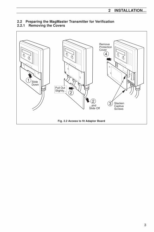
2.2 Preparing the MagMaster Transmitter for Verification2.2.1 Removing the Covers
2 INSTALLATION…
Fig. 2.2 Access to fit Adaptor Board
2
2...andSlide Off
1 SlideDown
4
SlackenCaptiveScrews
RemoveProtectionCover
3
Pull Out Slightly...
4
…2 INSTALLATION
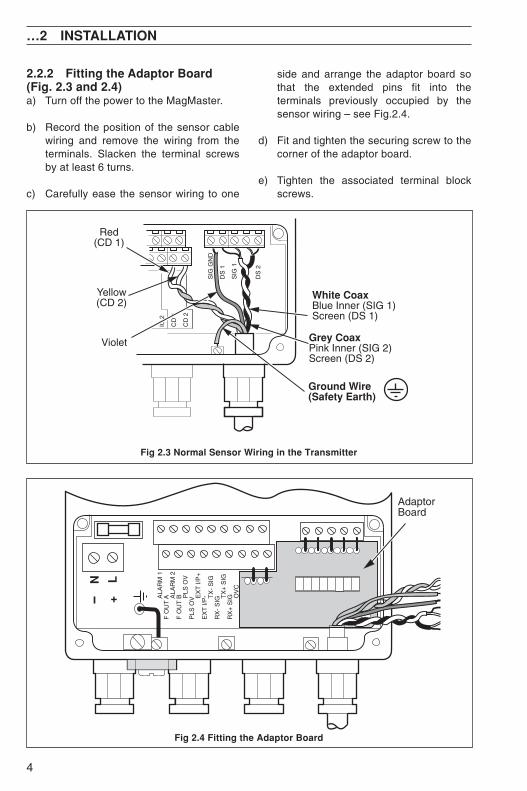
2.2.2 Fitting the Adaptor Board(Fig. 2.3 and 2.4)a) Turn off the power to the MagMaster.
b) Record the position of the sensor cablewiring and remove the wiring from theterminals. Slacken the terminal screwsby at least 6 turns.
c) Carefully ease the sensor wiring to one
side and arrange the adaptor board sothat the extended pins fit into theterminals previously occupied by thesensor wiring – see Fig.2.4.
d) Fit and tighten the securing screw to thecorner of the adaptor board.
e) Tighten the associated terminal blockscrews.
Fig 2.3 Normal Sensor Wiring in the Transmitter
Fig 2.4 Fitting the Adaptor Board
DS
2
IC 2
CD
1
CD
2
SIG
GN
D
DS
1
SIG
1
Grey CoaxPink Inner (SIG 2)Screen (DS 2)
Red(CD 1)
Yellow(CD 2)
White CoaxBlue Inner (SIG 1)Screen (DS 1)
Ground Wire(Safety Earth)
Violet
AdaptorBoard
ALA
RM
1F
OU
T A
ALA
RM
2F
OU
T B
PLS
OV
PLS
OV
EX
T I/
P+
EX
T I/
P-
TX
- S
IGR
X-
SIG
TX
+ S
IGR
X+
SIG
OV
C
N
+
L

5
…2 INSTALLATION
2.2.3 Wiring the Adaptor Socket(Fig. 2.5)The wires in the sensor cable must now bewired to the 8-way adaptor socket which willthen connect to the plug on the adaptorboard.
1 Adjust the wire lengths of the sensorcable to allow for termination andsubsequent removal of the adaptorsocket.
2 Insert the sensor cable wiring into thesocket as shown in Fig 2.5, and tightenthe plug screws with the screwdriverprovided.
Caution. Ensure that no bare wires toucheach other; in particular, ensure thatthere is no connection between thescreens of the grey and white coaxialwires.
3 Insert the adaptor socket into the plug onthe adaptor PCB.
Warning. Testing the MagMasterinvolves operation with the MagMasterterminal cover removed, exposing liveterminals. Take precautions to avoidelectric shock hazard.
Switch on the power to the MagMaster andcheck that the system operates correctly.
If the MagMaster operates correctly, eitherthe transmitter covers can be replaced fornormal working or the MagMaster can betested by the CalMaster.
Fig 2.5 Fitting the Sensor Wiring onto the Adaptor Socket
Blue
CD
1C
D2
GR
OU
ND
3
2
RedYellow
PinkGrey
White
Caution. Remove any exposedblack conductive layer from theinner insulation of both coaxialcables
VioletGround Wire
1
DS
2
DS
1S
IG 1
SIG
GN
D
SIG
2

6
…2 INSTALLATION
2.2.4 System Setup (Fig. 2.6)
Warning. Care is needed when CalMaster isused with cathodically protectedMagMasters.Cathodically protected installations, wired asdirected in the MagMaster manual, whichisolate the sensor using earthing flanges, areelectrically earthed and do not pose anysafety issues.When apparatus, such as CalMaster or thePC, are connected to systems which 'float' thesensor at the cathodic potential, thisapparatus will also float at the cathodicpotential and therefore must not be groundedor accidentally grounded.
With the adaptor PCB installed in the MagMasterTransmitter as detailed in Section 2.2.2, and thesensor cable plugged into the adaptor as fornormal operation:
Fig. 2.6 Connection Details for Initialisation
MagMaster CalMaster
1 2 3 4
Sensor
SensorTest Lead Set
ASEA BROWN BOVERI
CalMaster
a) Connect lead 3 of the CalMaster to theMagMaster 9-pin D-Type socket. The threesmall probes should not be connected untilrequested to do so by the CalMaster software.For details of when to connect these probeleads, follow the instructions on the providedsoftware – see Section 3.2. For details ofwhere to connect the probe leads, follow the'on-line help' under the heading, 'test leadconnections'.
b) Connect the 9-Pin D-Type socket on theCalMaster to a computer (Serial CommsConnection).
Note. The use of CalMaster with a linepowered desktop PC, as opposed to aportable, battery powered PC, is notrecommended, as the resulting ground(eqrth) loop can corrupt the sensitiveCalMaster measurements.In these circumstances, an external RS232isolator between the PC and the CalMasterwill effect a solution

7
3 OPERATION
3.1 Software Installation
Note. The CalMaster Program can beused with or without a 'Mouse'. Whereinstructions say 'Select', either click onthe item with the left hand mouse button,or use the 'TAB' key to move betweenfields and press the 'ENTER' key tocomplete the selection.
Insert the first CalMaster floppy disk into thecomputer disk drive and proceed as follows:
3.1.1 Windows 3.1 or 3.11a) Select 'RUN' from the Program or File
Manager menu.
b) Type 'a:setup' or 'b:setup', depending onthe floppy drive designation.
c) Press 'ENTER' and follow instructions.
3.1.2 Windows 95a) Press 'START'
b) Select 'Settings', 'Control Panel' anddouble click on 'Add/Remove Programs'.
c) Choose 'Install' and follow the instructions.
3.2 Initialising the CalMaster
Note. It is advisable to avoid the use ofradio equipment in the vicinity of aCalMaster/MagMaster test setup, duringtesting.
a) From Windows 'Program Manager' open the'ABB Applications' folder and double clickon the 'CalMaster' icon. The programautomatically finds the MagMaster and opensup to the Main 'ABB' Screen.
d) Select 'Test Meter', and the 'VerificationInformation' screen is displayed.
c) Follow the on–screen instructions andon–screen Help as required – click on theHelp button or press F1.
3.3 Battery ChargingThe CalMaster internal battery may becharged using the mains charger unitsupplied, or from a 12 volt vehicle connectorfor which a lead is also supplied.
Charging is automatic and takesapproximately 4 hours for a dischargedbattery.
For further information, refer to <batterymonitoring> from the CalMaster <options>menu.
…3 OPERATION

8
NOTES

PRODUCTS & CUSTOMER SUPPORTProducts
Automation Systems• for the following industries:
– Chemical & Pharmaceutical– Food & Beverage– Manufacturing– Metals and Minerals– Oil, Gas & Petrochemical– Pulp and Paper
Drives and Motors• AC and DC Drives, AC and DC Machines,
AC motors to 1kV• Drive systems• Force Measurement• Servo Drives
Controllers & Recorders• Single and Multi-loop Controllers• Circular Chart , Strip Chart and Paperless
Recorders• Paperless Recorders• Process Indicators
Flexible Automation• Industrial Robots and Robot Systems
Flow Measurement• Electromagnetic Magnetic Flowmeters• Mass Flow Meters• Turbine Flowmeters• Wedge Flow Elements
Marine Systems & Turbochargers• Electrical Systems• Marine Equipment• Offshore Retrofit and Referbishment
Process Analytics• Process Gas Analysis• Systems Integration
Transmitters• Pressure• Temperature• Level• Interface Modules
Valves, Actuators and Positioners• Control Valves• Actuators• Positioners
Water, Gas & Industrial AnalyticsInstrumentation
• pH, conductivity, and dissolved oxygentransmitters and sensors
• ammonia, nitrate, phosphate, silica,sodium, chloride, fluoride, dissolvedoxygen and hydrazine analyzers.
• Zirconia oxygen analyzers, katharometers,hydrogen purity and purge-gas monitors,thermal conductivity.
Customer Support
We provide a comprehensive after sales service via ourWorldwide Service Organization. Contact one of thefollowing offices for details on your nearest Service andRepair Centre.
United KingdomABB LimitedTel: +44 (0)1453 826661Fax: +44 (0)1453 829671
United States of AmericaABB Inc.Tel: +1 215 674 6000Fax: +1 215 674 7183
Client WarrantyPrior to installation, the equipment referred to inthis manual must be stored in a clean, dryenvironment, in accordance with the Company'spublished specification.Periodic checks must be made on theequipment's condition. In the event of a failureunder warranty, the following documentationmust be provided as substantiation:
1. A listing evidencing process operation andalarm logs at time of failure.
2. Copies of all storage, installation, operatingand maintenance records relating to thealleged faulty unit.

The Company's policy is one of continuous productimprovement and the right is reserved to modify the
information contained herein without notice.
Printed in UK (08.09)
© ABB 2009
ABB Inc.125 E. County Line RoadWarminsterPA 18974USATel: +1 215 674 6000Fax: +1 215 674 7183
ABB has Sales & Customer Supportexpertise in over 100 countriesworldwide
www.abb.com
ABB LimitedOldends Lane, StonehouseGloucestershireGL10 3TAUKTel: +44 (0)1453 826661Fax: +44 (0)1453 829671
IM/C
ALM
AS
Issu
e 3