user and maintenance manual - revodix.co.kr · 3 index 1 general information pag.5 1.1...
TRANSCRIPT

1
USER AND MAINTENANCE Manual

2

3
INDEX 1 GENERAL INFORMATION Pag.5
1.1 CERTIFICATION 1.2 TESTING AND WARRANTY 1.3 AIM, CONTENT AND ADRESSEES OF THE MANUAL 1.4 CLIENT’S RESPONSIBILITIES 1.5 INSTRUCTIONS FOR SERVICE REQUESTS
2 DESCRIPTION OF THE PRODUCT Pag.6
2.1 TECHNICAL DESCRIPTION 3 SAFETY Pag.7
3.1 GENERAL SAFETY RULES 3.2 INTENDED USE 3.3 CONTRAINDICATION 3.4 SAFETY ACCIDENT PREVENTION 3.5 ADOPTED SAFETY DEVICES
4 TRANSPORT AND HANDLING Pag.8 4.1 TRANSPORT AND HANDLING 4.2 POSITIONING 4.3 WIRING AND ELECTRICAL HOOK UP 4.4 SETUP OPERATIONS
4.4.1 PRELIMINARY CHECKS 4.4.2 INDICATION FOR OPTIMAL USE 4.4.3 SPECIAL WARNINGS FOR SUPERARTIC AND PLASMA RANGE 4.4.4 INTERNAL FITTINGS FOR NEW RANGE 4.4.5 INTERNAL FITTINGS SUPERARTIC RANGE
5 CONTROL PANEL ECT-F Pag.13
5.1 DESCRIPTION CONTROL BOARD ECT-F 5.2 FUNCTIONING ECT-F CONTROL
5.2.1 SWITCHING ON 5.2.2 SWITCHING OFF 5.2.3 HOW TO CUSTOMISE THE DISPLAY
5.2.4 ECT-F CONTROL MENU DESCRIPTION 5.2.5 HOW TO CHANGE THE TEMPERATURE SETPOINT 5.2.6 SPECIAL FUNCTION: DOCTOR VIEW
5.2.7 ALARMS AND FAILURES 5.2.8 DEFROSTING 5.2.9 PASSWORD 5.2.10 HOW TO SET THE CLOCK 6 CONTROL PANEL ECT-F TOUCH Pag.21
6.1 DESCRIPTION CONTROL BOARD ECT-F TOUCH 6.1.1 USER HARDWARE INTERFACE 6.2 FUNCTIONING ECT-F TOUCH CONTROL 6.2.1 SWITCHING ON 6.2.2 SWITCHING OFF 6.2.3 DESCRIPTION PANEL INFO 1 6.2.4 DESCRIPTION USER PANEL ECT-F TOUCH 6.2.5 SET TEMPERATURE CHANGE 6.2.6 TEMPERATURE ALARM LIMITS CHANGE 6.2.7 ALARM LIST 6.2.8 OPENING DOOR LIST
6.2.9 NIGHT & DAY FUNCTION 6.2.10 DESCRIPTION SETUP SYSTEM MENU

4
INDEX 6.2.11 PASSWORD 6.2.12 TEMPERATURE DATA BACKUP FROM USB 6.2.13 TEMPERATURE DATA BACKUP FROM SD CARD 6.2.14 ALARMS AND FAILURES SIGNALIZATION 6.2.15 TEMPERATURE GRAPHIC VISUALIZATION 6.2.16 MULTIMEDIA CONTENTS: TUTORIAL 6.2.17 DEFROSTING
7 ELECTRICAL SAFETY FUSES______ ______________________________ Pag.33 8 DMLP TOUCH DIGITAL MONITOR ______________________________________ Pag.34
9 ORDINARY AND PROGRAMMED MAINTENANCE ___ Pag.34
9.1 PROHIBITION OF SAFETY DEVICES REMOVAL 9.2 CLEANING OF THE EQUIPMENT INSIDE AND OUTSIDE 9.3 CLEANING OF THE CONDENSER 9.4 CONDENSATE WATER DRAINING 9.5 BATTERIES REPLACEMENT (if present)
10 EXTRAORDINARY MAINTENANCE AND REPAIRS ___ _Pag.36 10.1 PROTECTION REMOVAL
10.1.1 BOTTOM PANEL 10.1.2 TOP FRONT PANEL AND ELECTRIC CIRCUIT COVER
11 DEMOLITION ___ _ Pag.37 12 ANNEXES ____ Pag.38 13 DATA PLATES ___ _ Pag.38 13.1 DATA PLATES WITH EQUIPMENT CHARACTERISTICS
13.2 DATA PLATES OF WARNINGS
14 CONSUMABLES ___ _ Pag.39 15 DIAGNOSTIC____________________________________________ _________ __ Pag.40

5
1 GENERAL INFORMATIONS 1.1 CERTIFICATION All appliances are manufactured in compliance with the CE directives applicable at the moment of their placing on the market. All appliances are certified according to the directives 2006/42/CE, 2006/95/CE, 2004/108/CE and further amendments and they are manufactured taking into account the safety standards of electrical appliances used in laboratories (CEI EN 61010-1). Medical devices (for the storage of blood and blood related products) are, on the contrary, produced in line with directive 93/42/CEE. 1.2 TESTING AND WARRANTY The equipment is tested in our premises in compliance with the existing rules and it is ready to be used. The warranty is valid for 12 months from the date of delivery and covers the repair or the replacement of defective parts, with the exception of electrical parts and electronic components. Manifest defects or any difference from the orders must be communicated to the manufacturer within 5 days from the receipt of goods or they will not be covered by the guarantee terms. Any hidden or other defects must be communicated to the manufacturer within five days from their discovery and in anyway within the maximum guarantee term of six months. The purchaser shall be entitled to ask only for the repair or replacement of parts. The purchaser is not entitled to claim compensation for direct or indirect damages of any whatsoever nature. In any event, the entitlement for the repair or replacement of the materials must be exercised within the maximum term of the guarantee, which is contractually stipulated to cover a shorter period than the maximum term of the guarantee, which is contractually stipulated to cover a shorter period than the maximum term established by law. Repairs or replacement of defective materials will be carried out at manufacturer's premises; the sent back materials must be shipped on ex-works basis and will be returned to the purchaser at his expenses. 1.3 AIM, CONTENT AND ADRESSEES OF THE MANUAL This manual has been prepared with the aim of supplying all the instructions required for the correct use of the appliance and to maintain it in optimal working conditions. It also contains important safety information for the user. The following professional roles are explained in order to define the responsibilities of each person involved: Installer: qualified technician who installs and commissions the appliance following the instructions included in this manual. User: the person who, after having read this manual, uses the appliance in accordance with the intended use specified in this manual. The user is obliged to read the manual carefully and refer constantly to the information in it contained. Ordinary maintenance worker: qualified technician able to perform ordinary maintenance of the appliance by following the instructions in this manual. Extraordinary maintenance worker: qualified technician, authorized by the manufacturer, to perform extraordinary maintenance of the appliance.

6
The manufacturer disclaims any liability for misuse or for not foreseen uses of the equipment and for all operations carried out that are not in compliance with the instructions written in this manual. This manual must be kept in a place accessible and known to all the operators (installer, user, ordinary maintenance worker, extraordinary maintenance worker). This manual must not be reproduced or disclosed, in whole or in part, using any whatsoever mean or in any whatsoever form. 1.4 CLIENT’S RESPONSIBILITIES The customer is required to: - do the electrical connection of the appliance - prepare the place of installation - provide cleaning products - perform ordinary maintenance In case of power failure or malfunctions, do not open the door in order to maintain uniform temperature inside the cabinet. If the problem persists for many hours, we suggest moving the stored products in a more suitable place. 1.5 INSTRUCTIONS FOR SERVICE REQUESTS For any technical problem and for any technical service requests, refer exclusively to your local dealer (see space in the last page) or directly to the manufacturer, specifying model and serial number of the equipment. 2 DESCRIPTION OF THE PRODUCT 2.1 TECHNICAL DESCRIPTION The refrigeration of the internal cabinet is the result of low-pressure steaming of a refrigerant liquid, type HCFC or HFC, in a thermal exchanger (evaporator). The obtained steam is brought to the original liquid state through a mechanical compression at higher pressure (compressor), followed by a cooling stage in another thermal exchanger (condenser). The correct and uniform distribution of the cold air into the chamber is granted by one or more electro-mechanical fans (according to the model). The appliance consists of a modular single structure coated with various materials and insulated in expanded polyurethane foam, density 43 Kg/m³. The controller is in the in the front panel. In some models, the user can find behind the front panel the refrigerant unit represented by the condenser and the electrical loom. The cabinet of the appliance is fitted with suitable racks for wire shelves, extractible drawers and, for some models, wire baskets. The doors are fitted with an automatic device and magnetic seal elements easily replaceable. During the design and construction stages, the engineers have adopted all the necessary measures to manufacture equipment compliant to specific safety requirements such as the internal corners rounded off, the external exhaust of the condensate liquid, lack of rough surface, fixed guards protecting moving or potentially dangerous parts, etc. The maximum grids or drawers load for any Fiocchetti model is 30 kg, and the weight should be uniformly distributed. IMPORTANT: if neon or led lights are broken or faulty, a light with similar features should be used for replacement. Our equipment has been developed for indoor use and it is not meant to be used outdoors.

7
3 SAFETY 3.1 GENERAL SAFETY RULES Read this manual carefully and follow the prescriptions contained herein. The user assumes full responsibility in case of operations carried out without observing the instructions in the manual. Primary general safety regulations: - do not touch the equipment with wet hands and/or feet - do not insert screwdrivers or other pointed objects into the guards or moving parts of the
appliance - do not pull the power cord to disconnect the appliance from the electrical mains - make sure that the appliance is not used by non-qualified personnel - before performing any clearing or maintenance on the appliance disconnect it from the
electrical mains by switching it off and disconnecting the plug - In case of failures or malfunctions, switch off the appliance and do not attempt to repair it
on your own. It is absolutely necessary to contact qualified personnel. 3.2 INTENDED USE This appliance has been conceived to be used in hospitals, laboratories, pharmacies, etc. It has been designed for the storage of products at a controlled temperature, within the following temperature ranges: MEDIKA / MEDIKA 2T +2°C +15°C LABOR 0°C +15°C LABOR 2T / PLASMA LABOR 2T C+ : 0°C +15°C / 0°C +15°C; C- : 0°C +15°C / -10°C -24°C EMOTECA +4°C EMOTECA TWIN +4°C VISION / PLASMA VISION -15°C -20°C VISION 2T / PLASMA VISION 2T +2°C +15°C / -15°C -20°C FREEZER /PLASMA FREEZER -10°C -25°C SUPERARTIC / PLASMA SUPERARTIC -20°C -40°C SUPERARTIC 2T / PLASMA SUPERARTIC 2T +2°C +10°C / -20°C -35°C TER +15°C +30°C SPARK PROOF +2°C +15°C All the above listed series of appliances are suitable for products storage; for this reason, we suggest to store only products already cooled, or frozen, depending from the equipment type. On request, we can supply the above models with different temperature ranges or with improved performances, like for instance equipment fitted with tropicalized cooling unit. We declare that any use outside of those allowed of the appliance are considered as “improper uses”, therefore the manufacturer declines all responsibility. IMPORTANT: to assure a correct functioning of the appliance, the set temperature must be always lower than the ambient temperature, exception made for TER series. 3.3 CONTRAINDICATION The appliance must not be used: - Exposing it to outdoors conditions - With reductions or multi-way adapters - In places subject to explosive atmosphere or with risk of fire - Near to heat sources In case the equipment is embedded in any type of furniture, a correct air flow of the condensing unit (compressor and fan motors) must be always ensured. If this is not guaranteed, the warranty will immediately expire.

8
3.4 SAFETY ACCIDENT PREVENTION The appliance embodies various features designed to assure safety and to protect the health of the user. The following list describes the protections adopted against mechanical risks: - Stability: the appliance is designed and built in order to guarantee its stability even in case
shelves/drawers are fully extracted, without any risk of tipping, falling or sudden movement.
- Surfaces, edges, corners: accessible parts of the appliance have no sharp corners, sharp edges or rough surfaces that could cause injury.
- Moving parts: they are designed, built and configured to avoid risk. Moving parts are protected by fixed guards to prevent accidental contact that could result in injuries
LIST OF MEASURES ADOPTED FOR THE PROTECTION AGAINST ADDITIONAL RISKS: o Electrical power: the appliance is designed, built and fitted with the aim of preventing the
risks of electric shock in compliance with established safety regulations o Noise: the appliance is designed and built to reduce risks at the minimum related to the
emission of the acoustic noise (lower than 70 dB). 3.5 ADOPTED SAFETY DEVICES It is strictly forbidden: - to tamper with or remove the evaporator cover that protects the user from the risk of
cutting on the heat exchanger fins - to remove the data plates fixed in the inside edge of the engine compartment showing
technical specifications and earth connection warning - to remove the data plates placed on the evaporator unit cover and near the electrical
wiring inside of the engine compartment, which warns the user to disconnect the electrical plug before working on appliance
The manufacturer declines any responsibility for safety of the appliance if the above recommendations are not observed. 4 TRANSPORT AND HANDLING 4.1 TRANSPORT AND HANDLING The appliance must be transported and handled exclusively in a vertical position paying attention to the instructions printed on the packing. This precaution is necessary to avoid contamination of the refrigerant circuit with compressor lube oil which may cause the failure of the valves, of the cooling coils and problems of engine starting. The manufacturer declines any responsibility for problems due to transport done in condition others than those specified above. The internal fittings (slides, wire shelves, drawers, baskets, etc.) are shipped inside the unit. The appliance is fixed on a wooden pallet by means of screws, wrapped with polyethylene and packaged in cardboard, wooden crate or wooden case. The appliance must be handled using a fork lift truck with suitable forks (forks length at least equal to 2/3 length of unit). In case the appliance should be laid down flat in order to bring it into the installation place, it is absolutely necessary to wait at least 6 hours before switching it on.

9
4.2 POSITIONING Incorrect positioning can cause damage to the appliance and create dangerous conditions for users. Therefore, the installer must observe the following general regulations: - make sure to maintain a minimum of 10 cm distance from the
walls - the room must be well ventilated - keep the equipment far from heat sources - avoid direct sunlight exposure - remove packing material - remove accessories from the inside of the unit and the
wooden pallet below the equipment - Position the appliance with the help of a spirit level. If
necessary, adjust the levelling feet of the unit (in the models fitted with adjustable feet) (fig.1)
- remove the protective PVC film from the external surfaces of the unit - clean the inside of the chamber with a cloth and alcohol in order to eliminate the
protective oil 4.3 WIRING AND ELECTRICAL HOOK UP The electric installation and connection must be performed by qualified personnel. For safety reasons the user must pay attention to the following indications: - check that the electric installation is suitably sized for the absorbed power of the unit - If the electrical socket and the plug of the power cord are incompatible, change the plug
with a suitable component, ensuring that the replacement part is approved, according to the laws in force.
- do not use reductions or multi-way adapters It is important to connect the appliance correctly to an efficient earth system, in compliance with the relevant legislation. If the power cord is damaged, it must be replaced by the manufacturer, by an authorized after sale service or by a trained technician in order to avoid any possible risk.
4.4 SETUP OPERATIONS To prevent errors and accidents, a series of checks for possible damages caused during transport, installation and hook-up operations must be performed before connecting the unit.
4.4.1 Preliminary checks: - check the condition of the power cord (it should not have cuts or chaffing) - check that the feet, door hinges and shelf supports are stable - check the condition of internal and external components (pipelines, heat exchanger elements, fans, electrical components, etc.); check also that all parts are firmly fixed into position - Check that the door gaskets and drawers have not been damaged (broken or scratched) and that the doors close and seal properly. - Check that the TFT display is not damaged ATTENTION:
While in use the equipment must be placed far from cross talks of engines, generators, infrared rays, radio transmitters, telephones which may have negative effects for the device.
Fig.1

10
4.4.2 Indication for optimal use - do not block the motor compartment air vents - Arrange the material on the suitable provided shelves or drawers. Do not place the
products directly on the base of the chamber, against the walls, doors or fixed guards of the unit
- make sure door is closed properly - keep the defrost water drain outlet clear - limit the frequency and duration of door openings; each time the door is opened, the
internal temperature will alter and there will be possible ice formations on the evaporator
- perform regular maintenance (see “Cleaning of the condenser” Par. 9.3 ) - load gradually the material at ambient temperature to allow correct refrigeration - The power supply must be as indicated in the technical data plate (+/- 10%) - Appliances are designed and built to work at particular ambient temperatures (see the
climatic classes of reference Par. 13.1) and at a relative humidity of 60%. In ambient working operations different from the specified, it will not be possible to achieve the performances declared from the manufacturer.
4.4.3 Special warnings for Superartic and Plasma range
These appliances have been designed and built to store and maintain products at a controlled temperature (the products should be stored when already frozen). The lowest working temperature is -40°C and the rotation of the stored products cannot exceed 5% daily.
4.4.4 Internal fittings for new range MEDIKA 100-140-170-200-250-300-400-500-700-1500 MEDIKA 2T 200-280-400-600-500-800-1000-1500 LABOR 100-140-170-200-250-300-400-500-700-1500 LABOR 2T 200-280-400-500-700 PLASMA LABOR 2T 200-280-400-500-700 EMOTECA / LAB-EMOTECA 100-140-170-200-250-300-400-500-700-1500 EMOTECA TWIN 170-250-400-700-1500 FREEZER 100-140-170-200-250-400-700-1500 PLASMA FREEZER 100-140-250-400-700-1500 SUPER ARTIC 250-400 PLASMA SUPER ARTIC 250-400 VISION 400-700 PLASMA VISION 400-700 VISION 2T 400-500-700 PLASMA VISION 2T 400-500-700 TER 140-200-400-700 SPARK-PROOF 400-700 The innovative system fitted of stainless steel racks (standard fitted) allow the possibility of having an internal fitting mixing shelves and drawers (mounted on telescopic slides) perfectly interchangeable (For eventual orders of additional shelves or drawers, please refer always to the model and serial number, see data plate paragraph 13.1). SUPERARTIC and PLASMA SUPERARTIC models fit drawers mounted on extractible slides (not telescopic). Position the shelves support in the rack at the desired position inserting them into the special slots (fig. 4) and turning them of 90° to block them. Once positioned the 4 supports at the same height level, it is possible to install the shelf (fig.3). In order to change the position of the drawers, extract the same, and once it is fully extracted, unlock it from the slides through the unlocking devices (plastic lever black colour) positioned on the side. The drawer is unlocked by pushing the right lever up and the left lever down at the same time. After that it is possible to remove the telescopic slides by lifting the front part (fig.2) of the slide up (to extract it from the rack in the front part) and pulling the slide

11
Position of drawer slides Position of shelf bracket
frontward, to extract the rear part. Repeat the same operations, but inverting the sequence to reposition the slides and the drawers. Fig.2 Fig.3 Fig.4 The wall-racks are even easily removable in order to allow a better cleaning of the interior of the appliance. The racks mounted in the front part can be removed pushing them upward (fig.5), while the ones mounted in the rear side can be removed by first, unscrewing safety fixing screw (using a cross screwdriver) positioned in the top part (fig.6), and then pushing against the internal wall the small plastic edge on the top part of the rack and simultaneously pulling the rack itself upward (Fig 5).
Fig.5 Fig.6
Push to unblock

12
4.4.5 Internal fittings Superartic range
SUPERARTIC 700 (fitted with shelves) PLASMA SUPERARTIC 700 (fitted with shelves) SUPERARTIC 2T 700 2T (fitted with shelves) PLASMA SUPERARTIC 2T 700 2T (fitted with shelves) Place the shelves supports on the rack at the desired position, insert them into the special slots (fig. 4) and turn them at 90° to block them. After having positioned the no. 4 supports at the same height level, it will be possible to install the shelf (fig.3). Some special models have “C” slides anti-tilt for the installation of the shelves or baskets. In order to install correctly the shelves and baskets you should follow these instructions: Place the shelves supports in the desired position; insert first the support into the wall-rack, and then insert the edge of the side of the slide into the wall-rack mounted on the internal side part at the corresponding height of the fixing in the rear. Finally, having inserted a pair of slides at the same height, insert the shelf between them (fig.7).
Fig. 7

13
5 CONTROL PANEL ECT-F
COOLING + 4.3 °C
5.1 DESCRIPTION CONTROL BOARD ECT-F
ECT-F CONTROL
1 / Alphanumeric LCD Display, back-lit
2
To confirm
3
To Enter and Esc from the menu
4
To increase values, scroll menu and for INFO DOCTOR VIEW special function
5
To decrease values, scroll menu. Switching on/switching off glass door LIGHT
5.2 FUNCTIONING ECT-F CONTROL Introduction The refrigerator/freezer is equipped with a latest generation Electronic Controller, with a back-lit LCD alphanumeric display, to display temperature and working operations with an accuracy of 0,1°C. The controller gives maximum safety in case of alarms and fault conditions, signalling critical conditions and recording every event in order to help the service engineer to speed up the analysis and thus the fixing of any problems. Safety is at the highest level with alarms for High and Low temperature, power-failure, door open as well as auto-test. What is more, the ECT-F Control is equipped with an internal clock to catalogue all the events.
3
4
21
5

14
5.2.1 SWITCHING ON*
Connecting the power cord of the equipment, the display will show “STAND-BY”, which indicates the presence of mains power. Pressing one of the buttons for two seconds the equipment will switch on. The display will show (in sequence) the welcome message, the software name and the firmware version. For correct data storage, please check hour and date (see Par. 5.2.3) the first time the equipment is turned on. If they are not right, modify them (see Par. 5.2.10). (*) The switching on of the equipment can be protected with a password. If user password = 00 the user can switch on the equipment without the request of a password).
5.2.2 SWITCHING OFF*
Press the button , on the display appears, then press
The controller requires a confirmation of the command: To confirm, press again the button , or to cancel (Esc) and return to main menu. Important: to go out from the different menus, press to go back to display of the actual working condition. (*) The switching off of the equipment can be protected with a password. If user password = 00 customer can switch off without the request of a password). 5.2.3 HOW TO CUSTOMISE THE DISPLAY When ECT-F is switched on, the display can be customised with 4 different modes of display using the button
(Optional with humidity probe)
Mode 1 (Default) Mode 2 Mode 3 Mode 4
Working status and Date and time Setpoint and Relative humidity % Temperature temperature and temperature (only with humidity
sensor installed)
<<Confirm Esc>>
TURN OFF m1
PAUSE +4,5°C
12:44 12/03/06
S +4,0°C / +4,5°C
56%Rh +4,5°C

15
Working status description on the display
5.2.4 ECT-F CONTROL – MENU DESCRIPTION
With the button access to the available functions. Scroll the menu using the buttons
and .
STRING DESCRIPTION OF THE OPERATION IN PROGRESS PAUSE Compressor is OFF, waiting next cooling cycle COOL Compressor is ON to reach setpoint
WAIT DEFROST After request of manual defrosting, the controller waits for the necessary conditions to proceed automatically with defrosting
ACCESS DENIED Attempt to access a disabled menu or deny to run a manual defrost if the conditions are not suitable for such action.
DEFROST The equipment defrosts, warming up the evaporator DRIPPING Last phase of the defrosting to allow dripping of condensate water RECOVERY Compressor is ON after defrosting to re-acquire the setpoint DOOR Door open (close immediately!) HEATING Warming-up phase (ONLY FOR PRESET MODELS )
TURN OFF m1
CHANGE SET m2
CHANGE Rh% m3
DEFROST m4
DEEP FREEZE m5
ALARMS LIST m6
LANGUAGE m7
Switching off
Customise temperature setpoint
Customise humidity setpoint
Start defrosting
Start compressor on a time-base
Display ALARMS LIST
Set Date/Time
Choose LANGUAGE (IT/EN/FR/DE ES)
Important! The SERVICE Menu is accessible only with a password.
PASSWORD m8
Set the User password
SERVICE MENU m9
Access SERVICE MENU
CLOCK SET m10
(ONLY FOR PRESET MODELS)
(ONLY FOR PRESET MODELS)
16
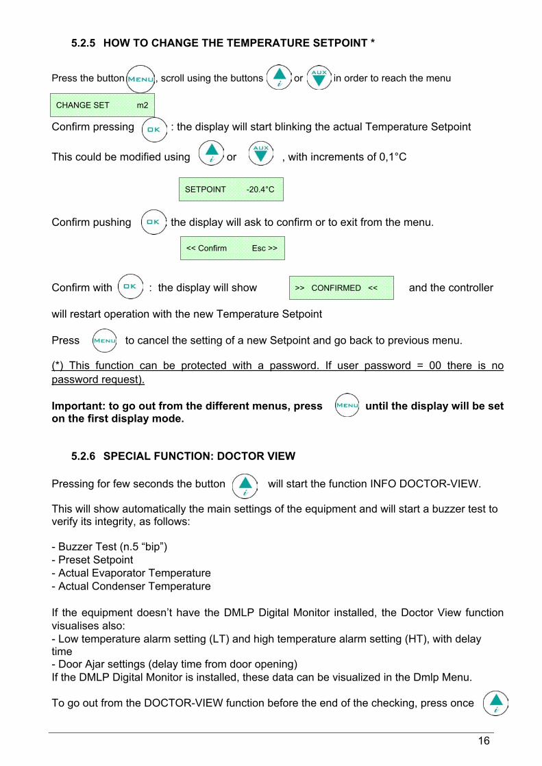
5.2.5 HOW TO CHANGE THE TEMPERATURE SETPOINT * Press the button , scroll using the buttons or in order to reach the menu Confirm pressing : the display will start blinking the actual Temperature Setpoint This could be modified using or , with increments of 0,1°C Confirm pushing : the display will ask to confirm or to exit from the menu. Confirm with : the display will show and the controller will restart operation with the new Temperature Setpoint Press to cancel the setting of a new Setpoint and go back to previous menu. (*) This function can be protected with a password. If user password = 00 there is no password request). Important: to go out from the different menus, press until the display will be set on the first display mode.
5.2.6 SPECIAL FUNCTION: DOCTOR VIEW Pressing for few seconds the button will start the function INFO DOCTOR-VIEW. This will show automatically the main settings of the equipment and will start a buzzer test to verify its integrity, as follows: - Buzzer Test (n.5 “bip”) - Preset Setpoint - Actual Evaporator Temperature - Actual Condenser Temperature If the equipment doesn’t have the DMLP Digital Monitor installed, the Doctor View function visualises also: - Low temperature alarm setting (LT) and high temperature alarm setting (HT), with delay time - Door Ajar settings (delay time from door opening) If the DMLP Digital Monitor is installed, these data can be visualized in the Dmlp Menu. To go out from the DOCTOR-VIEW function before the end of the checking, press once
CHANGE SET m2
SETPOINT -20.4°C
<< Confirm Esc >>
>> CONFIRMED <<

17
5.2.7 ALARMS & FAILURES Alarm Warning The buzzer starts and the display blinks, showing (alternately) the alarm code and the mode of the preset visualisation mode. The event is then recorded in the ALARM LIST. The Controller stores the latest 12 alarms and, for every alarm, the following details:
• TYPE OF ALARM • CRITICAL TEMPERATURE REACHED • DURATION of the alarm (for High/Low temperature alarm) • DATE/TIME alarm beginning and end (only for POWER FAILURE) The Buzzer can be muted by pressing any button of the Controller (the display will keep blink continuously) Alarms Codes Description • HIGH TEMPERATURE: code < HT > • POWER FAILURE: code < B > • LOW TEMPERATURE: code < LT > • DOOR OPEN: code < Door > Failure/Alarm messages description
Alarm Warning
When the alarm condition is finished, the display will alternately (every 4 sec.) visualize the message with the standard preset display , until the User will access the ALARM LIST menu: .
MESSAGE TYPE OF CRITICAL CONDITION PROBE S1 Faulty cabinet sensor (call Service) PROBE S2 Faulty evaporator sensor (call Service) PROBE S3 Faulty condenser sensor (call Service) LOW EVAP Evaporation LOW temperature (see diagnostic paragraph no.15) HIGH CONDENS Condenser HIGH temperature (see diagnostic paragraph no.15) h00:m00 Clock-data loss (see diagnostic paragraph no.15) DEFROST TIME Inadequate defrosting time (see diagnostic paragraph no.15)
COMPRESSOR WORK Maximum allowed continuous working % during the last 24 hours of the compressor (see diagnostic paragraph no.15)
32C Events/Strings memory failure (call Service) DIRTY COND Inadequate thermal exchange: clean the condenser ALARM NOTICED Temperature alarm occurred, in the presence or absence of mains
IN CASE OF S1 FAILURE, THE EQUIPMENT WILL STILL CONTINUE TO FUNCTION CORRECTLY UNTIL THE ARRIVAL OF A SERVICE ENGINEER.
> NOTICED ALARM <
ALARMS LIST m6

18
Recorded Alarm List Visualisation Press the button and using button or scroll the menu till Confirm pressing : the display will show The number indicated shows the total number of alarm occurrences since the last reset. In case of no alarms, the display will show “NO EVENT NOTICED” In case of alarms, press to access the alarm menu and display all the necessary information/details. Pressing continuously the button , the beginning date/hour (S) and ending date/hour (E) are displayed.
Important: to go out from the menus, press until the preset visualisation is displayed.
5.2.8 DEFROSTING The equipment provided with the ECT-F Control has an advanced managing of the defrosting cycles. The defrosting is operated only if necessary, thus drastically reducing the number of cycles for a cost-effective operation. For this reason, a manual defrosting has never to be operated. If, for any reason, and ONLY after contacting Service, a manual defrosting is necessary, follow this procedure: Press the button and with or go to the menu Confirm using the button and the display will show the message:
DEFROST m4
DETECTED n. 07
The list is displayed from the last one to the first one, pressing the button . The reading of the data is as per here under diagram:
A08 H +29°C 199’
Number of memorised alarms
Alarm code: H= High temp. L= Low temp. B= Power-failure
Duration of the alarm in minutes. For power-failures, the duration is not listed. (*)
Critical temperature reached during the alarm condition
S 14:10 24/08/06
E 14:34 24/08/06
ALARMS LIST m6
<< Confirm Esc >>

19
Press to confirm the operation of manual defrosting. Press the button to cancel (Esc) and go back to the main menu. Confirming with the button the operation of manual defrosting will start. On the display appears the message “DEFROST” followed by “DRIPPING” and “RECOVERY” (phases of the defrosting). We’d like to draw your attention to the advanced defrosting function that normally avoids the use of this procedure: if the manual defrosting operation is confirmed, the Controller awaits the necessary condition to start the cycle. In this phase, the display will continue to show every 4 seconds the operations in progress, alternately to the message If the conditions for a defrost are totally absent, the controller will display the message:
5.2.9 PASSWORD Press the button and with or go to the menu This menu will give you the possibility to set a new USER PASSWORD to protect SWITCHING ON and SWITCHING OFF the controller, together with the TEMPERATURE SETPOINT. The controller is factory set with password = 00, which allows the user to turn on, off the equipment and to modify the setpoint freely. Set the PASSWORD Press the button and choose a number between 1 and 255 using and , to confirm using the button . Modify the PASSWORD Press the button : the actual password is now required. Use and to insert the password (from 1 to 255) and confirm with the button . If correct, it is possible to modify the old password. To finish the procedure, press again If the PASSWORD is wrong, the display will show “WRONG PASSWORD” and the controller will automatically go to the main menu. If the PASSWORD is set to 00, the protection will be deactivated. ATTENTION! If the USER PASSWORD is lost, there is no possibility to retrieve it.
WAITING DEFROST
PASSWORD m8
ACCESS DENIED

20
5.2.10 HOW TO SET THE CLOCK Press the button and with or go to the menu Press then : the display will blink with actual date and time. Modify the values with and , then press to confirm the value; continue until all the values are set. To ensure correct storage of the information, the ECT-F Control has an alarm to signal eventual loss of date/hour, shown on the display with a blinking message (this means that the clock battery is discharged – see diagnostic Par. 15 – and must be replaced).
CLOCK SET m10
14 : 35 18 / 01 / 07
H: 00:00 m 00:00

21
Graph
INFO 1 Panel
Equipment name
6 CONTROL PANEL ECT-F TOUCH 6.1 DESCRIPTION CONTROL BOARD ECT-F TOUCH
Equipment with one chamber
Equipment with two chambers
INFO Panel 1st chamber Graph 1st chamber
Graph 2nd chamber INFO Panel 2nd chamber
INFO 2 Panel Equipment status
STATUS Panel
Date/Hour

22
Equipment with one chamber + ballasted probe Panel INFO 1 Panel INFO 2
Product temperature Product alarm Min/Max limits Screensaver mode: it is possible to set the screensaver page which will be automatically activated if the screen is not in use for a certain period of time (see “Description setup system menu” par. 6.2.10). The screensaver page will show the chamber temperature against a black background easily readable from the distance. The screensaver page will disappear at the touching of the screen.
6.1.1. USER HARDWARE INTERFACE
USB slot for Software update, programming and for the backup temperature data. SD card to register all functional data of the system, temperatures and technical documents in digital format. SIM Card Slot for GSM modem (optional)
6.2 FUNCTIONING ECT-F TOUCH CONTROL Introduction The fridge is equipped with a latest generation Electronic Controller with a TFT display of 7” Touch screen. This screen visualizes the temperature and the functioning status of the equipment with an accuracy of 0,1°C. This instrument guarantees maximum safety in case of alarms and failures, signaling promptly critical conditions and recording each event in order to help the Service engineer to speed up the analysis and the repair of faulty conditions. Safety is at the highest level by means of alarms for High and Low temperature, power failure, open door as well as auto test to prevent failures. Safety is also assured in case of faulty compressor relays or faulty defrost relays in order to prevent the freezing or overheating of products.

23
The instrument records every 30 Seconds the equipment temperatures with a resolution accuracy of 0,1°C. Data are registered in two memories: the first is a flash memory able to store 1 year operations; the second memory is represented by Secure Digital (SD) which works as a black box since it can store up to 10 years of data. In the display it is possible to charge data to build graphs from both memories. The registered information in the SD is the following: • Day of the week, date and hour • Temperature chamber A and B (Chamber – Evaporator - Condenser) • Temperature chamber A and B (Chamber A e Chamber B with DMLP TOUCH) • Product simulator temperature (only with DMLP TOUCH) • Programmed Setpoint • Status door chamber A and B (Opening – Closed) • Duration door opening chamber A and B • Relay status to remote alarms (Dry contact) • Buffer battery tension (if present) • Presence/absence of the mains • Humidity probe temperature (if present) • High and Low alarms of temperature for both chambers and alarm delays (only with
DMLP TOUCH) • Alarm and failure codes
6.2.1 SWITCHING ON
Once connected the equipment to the mains, the display will show the “STAND-BY” page which means that power is on. Pressing the three red squares sequentially from left to right, the equipment will turn on. Only at the first turning on of the equipment it is automatically requested to select language, date and hour.
6.2.2 SWITCHING OFF

24
A or B refrigerant unit (only for TWIN version) Mode in progressN&D function
on
Alarm/failure in progress or over
Touch the green arrows to browse pages or touch the “Home” symbol to go back to homepage.
In order to switch off the equipment, it is necessary to press the USER PANEL icon and then press the SYSTEM OFF one. The screen will ask to confirm again. Therefore, to confirm the
system turning off press or to cancel the operation. ATTENTION: If the Control user password is enabled, user should enter the right password in order to switch off the system.
6.2.3 DESCRIPTION PANEL INFO 1
Touch the temperature value to visualize all the useful information of the equipment both for the user and for the Service.
MESSAGE MODE IN PROGRESS
PAUSE Compressor is OFF, waiting for next cooling cycle COOLING Compressor is ON to reach setpoint DEFROST The equipment is defrosting, i.e. warming up the evaporator DRIPPING Last phase of the defrost cycle to allow dripping of condensate water RECOVERY After a defrost cycle the compressor is ON to reach again the setpoint HEATING Warming up phase is ON (ONLY FOR PRESET MODELS)

25
6.2.4 SET TEMPERATURE CHANGE Touch in the homepage the Setpoint value in order to access to the dedicated page. Enter the new value and press “OK”. Together with the Setpoint, user can find also information about the compressor switching on/off differential and of the Running setpoint (this differs from the “Current setpoint” when the Night & Day function is active). ATTENTION: At every temperature change, user should always check that the set limits are modified accordingly. If not, user should change them (see par. 6.2.6). According to the stored products, the limits must be set some degrees higher and lower the setpoint: the lower limit must always be 2°C or 3°C lower than the setpoint; whereas, the upper limit must always be 2°C - 5°C more than the setpoint. For instance, for the storage of drugs, user may set the setpoint at 8°C, lower limit at 6°C and upper limit at +11°C. For the storage of blood at 4°C the limits must be set at +2°C and +6°C.
6.2.5 TEMPERATURE ALARM LIMITS CHANGE Touch in the Homepage the Lower and Upper Limit value in order to modify limits in the dedicated page. Enter the new value and press “OK”. In the dedicated page the user can also modify the delay for the signalization of the alarm and of door opening.

26
6.2.6 DESCRIPTION USER PANEL ECT-F TOUCH
ICONS DESCRIPTION
Turns off the equipment.
To visualize the latest n.32 registered alarms.
To visualize the latest n.32 door openings.
This icon let user enter in the Night & Day function
Runs a manual defrost
Access to Multimedia information (TUTORIAL)
To change date and hour
To set languages
USER SETUP MANAGEMENT
Pressing this icon all the registered users as well as the related enabling will be visualized.
Pressing it user can backup the temperature registered data.
To enter in the SERVICE Menu (ONLY by means of a password)

27
6.2.7 ALARM LIST
In this list you can see type of alarm, date/hour of alarm beginning, duration and critical temperature attained.
6.2.8 OPENING DOOR LIST
In the list you can see the last 32 openings and in particular date, duration of each opening, total number of openings in a day and the no. of critical openings (>30 sec.) 6.2.9 ELECTRIC DIGITAL KEY LOCK As safety device against unauthorized door opening, the equipment can be fitted with an electric-digital key locking, consisting in a small piston placed in the upper corner of the door of the machine (optional). The door is opened by means of a gentle pressure on the key icon in the homepage.
During the door opening period, the piston will be automatically release, to allow an immediate door closing. After having enabled the “Password” function from the SET UP SYSTEM using the password 0000, the machine can be protected against the opening of non-authorized users. The generic user password is 1234 (see par. 6.2.12 Password).
Use the blue arrows to browse the list
Use the blue arrows to browse the ALARM LIST

28
From the Service menu, Admin users submenu, it will be possible to create specific users profiles, each of them enabled to open the door using a customized password; this section will also visualize how many door opening have taken place in a specific day, and who did them. In case of power failure, the door can be opened using the dedicated key, standard supplied, placed into the documents envelope inside the equipment chamber.
Press the key towards the piston with a perpendicular movement; the piston will move upwards letting the door open.
6.2.10 NIGHT & DAY FUNCTION
This is a special function which allows saving energy during the night, holidays or when the equipment is not used frequently and doors remains closed by increasing the temperature of a default value (from 0.1°C to 2°C max). The programming of this special function can be made by the user by means of this window here below:
6.2.11 DESCRIPTION SETUP SYSTEM MENU In this menu the user has the possibility to customize some specific functions of the equipment.
Start hour Duration Increase SETPOINT (from 0 to 2°C)
Day/Time of Night & Day activation
On/Off Night & Day function (in case you have put as day of rest “HOLIDAYS” you should deactivate the function manually.
Anti-theft device

29
6.2.12 PASSWORD
Enabling the “User control password” from the SYSTEM SETUP icon entering PSW: 0000, it is possible to protect the equipment from no qualified personnel who may change important parameters for the correct functioning of the equipment. If the User control password is activated , a password will be asked for these operations:
• Switching on • Switching off • Date/hour change • Temperature Setpoint change • Min. and Max. alarm temperature limits change • Door opening (if the equipment has the digital electronic lock)
The USER password is 1234 and it can be changed only entering the Service Menu ADMIN USERS.
It enables to give a name to the equipment to be then visualized in the Home page.
It enables to enter a GSM number to send SOS SMS automatically in case of a complete system failure (Only if GSM Communicator 2011 is installed).
To run a functional TEST of the buzzer and to commute the Dry contact to remote alarms (10 Sec).
It enables to activate or disable the equipment audio.
To run a TFT upgrade.
To run a system reboot (MAKE A REBOOT ONLY IF NECESSARY)
To modify the internal light brightness (from 0 to 100%)
To modify the brightness of the display (MAX during the equipment functioning and MIN during the N&D and screen saver)
To activate or deactivate the User Password Setup enter PSW: 0000. The generic user password is 1234.
To activate Screen Saver each (h) hours (from 1 to12h or Never ---)
To setup day and hour for the system SMS (Only if GSM Communicator 2011 is installed)
To be used in case of buffer battery substitution in order to determine the battery life. Once replaced the batteries touch the light-blue square to
activate the flag. Automatically the new date will be written.

30
6.2.13 TEMPERATURE DATA BACKUP FROM USB This menu is useful in order to run a monthly backup of the temperature data by means of a USB. Enter the month/year you desire to copy, touch the following icon and follow the described procedure. Inside of the USB a folder with all the registered data will be automatically created. The name of the folder is a particular code which identifies the equipment; therefore, it is possible to load in the USB different backup of different equipment.
bck12345_1_12 We advise to use the SD card for the first download of data in order to install also the software CAPTURE 5.0 in the computer. Software CAPTURE 5.0 allows to read, create and print daily/weekly graphs of the backup data saved in the USB.
6.2.14 TEMPERATURE DATA BACKUP FROM SD CARD We suggest to save every two months in the computer the SD card registered data in order to prevent data loss in case SD CARD is lost or damaged. To make the backup of data, extract the SD CARD and make a copy of the Backup folder in your PC. The Software CAPTURE 5.0, available in the SD card, will allow to read, create and print daily/weekly graphs of the backup data saved in the USB. IMPORTANT: While the SD card is extracted, all data will be registered in anyway.
6.2.15 ALARMS AND FAILURES SIGNALIZATION Running alarm or failure When a failure or alarm is detected, in the display will appear the following icon and an acoustic alarm will be heard. Touch the icon in order to silence the acoustic alarm and visualize the description of the alarm. It is possible to touch the description of the failure in order to have more information also about the possible solution of the problem. Once visualized the description, in the
BACKUP Serial number
Month and Year

31
homepage the icon of alarm will appear littler and near the temperature of the chamber in order to signal that the alarm is still running. If after 30 minutes, the Failure/Alarm persists, the acoustic alarm will be reiterated and the alarm icon will appear again in the middle of the display. Alarm or failure notice ended When the alarm or failure is ended, the user will continue to be informed in the Homepage both visually (with a dedicated icon) and acoustically (“beep-beep-beep” every 2 min) until he won’t visualize the type of alarm or failure. In order to visualize the type of alarm touch the icon in the display. Once back to the Homepage the icon will automatically disappear. 6.2.16 TEMPERATURE GRAPHIC VISUALIZATION In the Homepage a temperature graph of the last 6 hours is constantly built and visualized. Touching the graph the user can enter the menu “GRAPHIC DETAIL”.
By means of the following icons , , , it is possible to visualize immediately the current daily time spans graphic details.
Touching is, on the contrary, possible to analyze the past registered temperature data.
Additional information
DMLP failure ECT-F failure Temperature
Alarm
Silenced running alarm
ALARM RUNNING
32
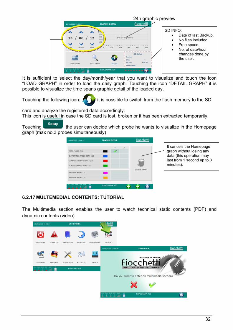
24h graphic preview It is sufficient to select the day/month/year that you want to visualize and touch the icon “LOAD GRAPH” in order to load the daily graph. Touching the icon “DETAIL GRAPH” it is possible to visualize the time spans graphic detail of the loaded day. Touching the following icon: it is possible to switch from the flash memory to the SD card and analyze the registered data accordingly. This icon is useful in case the SD card is lost, broken or it has been extracted temporarily.
Touching the user can decide which probe he wants to visualize in the Homepage graph (max no.3 probes simultaneously) 6.2.17 MULTEMEDIAL CONTENTS: TUTORIAL The Multimedia section enables the user to watch technical static contents (PDF) and dynamic contents (video).
SD INFO: • Date of last Backup. • No files included. • Free space. • No. of date/hour
changes done by the user.
It cancels the Homepage graph without losing any data (this operation may last from 1 second up to 3 minutes).

33
Pressing this icon , the user will go back to the Home page. When the user decides to exit the tutorial section, the system will be activated again and this will take 1-2 minutes. Despite this, the equipment will continue working normally
6.2.18 DEFROSTING Equipment fitted with ECT-F TOUCH controller is provided with an advanced managing of the defrosting cycles. The defrosting is operated only if necessary, thus drastically reducing the number of cycles for a cost-effective operation. For this reason, a manual defrosting has never to be operated. Only if the correct (according to the controller) conditions are present, the end user can run a manual defrost. Each defrosting phase is described in Panel INFO1 of the Home page. 7 ELECTRICAL SAFETY FUSES The equipment is supplied with safety fuses (6.3X32) of 10A or 15A (it depends on the model) against electric shocks, over-currents and short circuits. Opening the door, the fuses are behind the frontal panel. Using a screwdriver unscrew the fuses’ case and in case of failure substitute them.

34
8 DMLP TOUCH DIGITAL MONITOR
Introduction The equipment can be supplied with DMLP Touch Digital Monitor. This instrument is completely independent from the ECT-F touch controller. It records independently temperatures – by means of a PT100 probe – and signals temperature alarms or power failures (using a back-up battery supplied as standard automatically recharged). Safety is at the highest levels with alarms for High and Low temperatures power failure, door open and diagnostic tests. Data are registered in two memories: the first is a flash memory able to store 1 year operations; the second memory is represented by Secure Digital (SD) which works as a black box since it can store up to 10 years of data. Thanks to the buffer battery, the temperature record is guaranteed up to 12 hours also in case of power failure. The DMLP Digital Monitor has as standard no. 2 dry contacts. IMPORTANT: DMLP Digital Monitor is equipped with a buffer battery represented by no. 8 Nihm rechargeable batteries type AA of 1.2 Volt (the batteries may be either in the back of the equipment – equipment with motor in the lower part - or in some models in the top part). The life of the battery goes generally from 2 to 3 years, according to the number of recharge cycles and ambient temperature. After this period, the battery will have to be replaced with a unit with the same features. The DMLP Digital Monitor will display a message informing the user that the replacement is necessary. In case of long term disconnection of the equipment from the mains (3-6 months) the life of the battery may be shortened. For this reason, we suggest to keep the system always ON. In case of power failure, the battery, if in good conditions, will maintain the DMLP active for 12 hours, during which the data recording is guaranteed. After this time, the DMLP will automatically turn off. After 12 hours the DMLP will turn off. The restoring of normal power conditions will turn on automatically and restart the equipment. 9 ORDINARY AND PROGRAMMED MAINTENANCE The information in this section is addressed to the end users, either as non-specialized personnel or as ordinary maintenance worker. 9.1 PROHIBITION OF SAFETY DEVICES REMOVAL Before removing guards, switch off the equipment and disconnect it from the mains. The manufacturer disclaims all liability that may arise if this regulation is not observed. 9.2 CLEANING OF THE EQUIPMENT INSIDE AND OUTSIDE The appliance is thoroughly cleaned in our factory before delivery. We recommend, however, that you clean the interior of the appliance before use. Before any cleaning operation, make sure that the appliance power cord is disconnected. Also we suggest cleaning both the interior and the exterior surfaces of the appliance at least twice a year. For more details see the below paragraph: - Cleaning products: water and non-abrasive neutral detergent. DO NOT USE SOLVENT
OR THINNERS - Cleaning method: use a cloth or sponge soaked in a suitable cleaning product to clean the
interior and exterior parts of the cabinet - Disinfection: do not use substances that could alter the basic characteristics of the stored
material - Rinsing: use a cloth or sponge soaked in clean water. DO NOT USE WATER JETS - Frequency: at least twice a year or at different intervals in accordance with the type of
pharmaceutical products stored
35
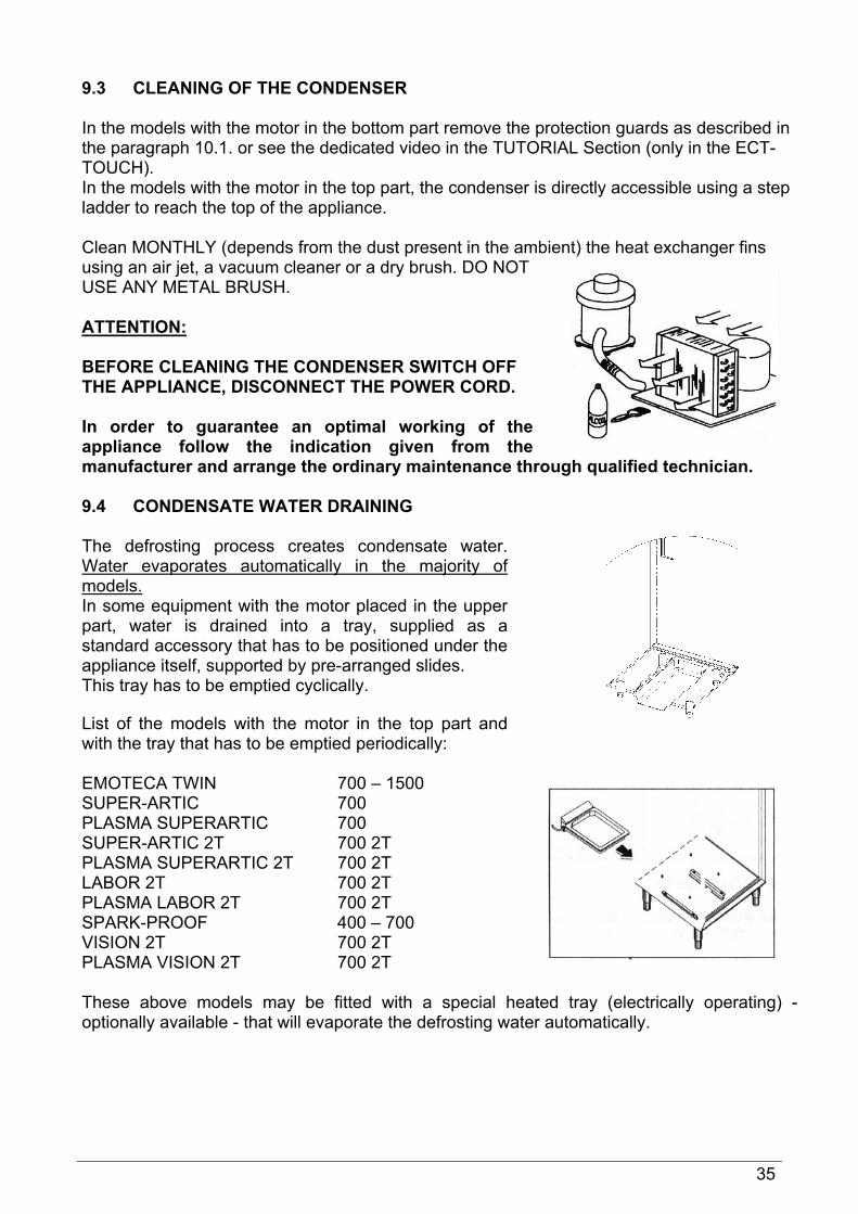
9.3 CLEANING OF THE CONDENSER In the models with the motor in the bottom part remove the protection guards as described in the paragraph 10.1. or see the dedicated video in the TUTORIAL Section (only in the ECT-TOUCH). In the models with the motor in the top part, the condenser is directly accessible using a step ladder to reach the top of the appliance. Clean MONTHLY (depends from the dust present in the ambient) the heat exchanger fins using an air jet, a vacuum cleaner or a dry brush. DO NOT USE ANY METAL BRUSH. ATTENTION: BEFORE CLEANING THE CONDENSER SWITCH OFF THE APPLIANCE, DISCONNECT THE POWER CORD. In order to guarantee an optimal working of the appliance follow the indication given from the manufacturer and arrange the ordinary maintenance through qualified technician. 9.4 CONDENSATE WATER DRAINING The defrosting process creates condensate water. Water evaporates automatically in the majority of models. In some equipment with the motor placed in the upper part, water is drained into a tray, supplied as a standard accessory that has to be positioned under the appliance itself, supported by pre-arranged slides. This tray has to be emptied cyclically. List of the models with the motor in the top part and with the tray that has to be emptied periodically: EMOTECA TWIN 700 – 1500 SUPER-ARTIC 700 PLASMA SUPERARTIC 700 SUPER-ARTIC 2T 700 2T PLASMA SUPERARTIC 2T 700 2T LABOR 2T 700 2T PLASMA LABOR 2T 700 2T SPARK-PROOF 400 – 700 VISION 2T 700 2T PLASMA VISION 2T 700 2T These above models may be fitted with a special heated tray (electrically operating) - optionally available - that will evaporate the defrosting water automatically.
36
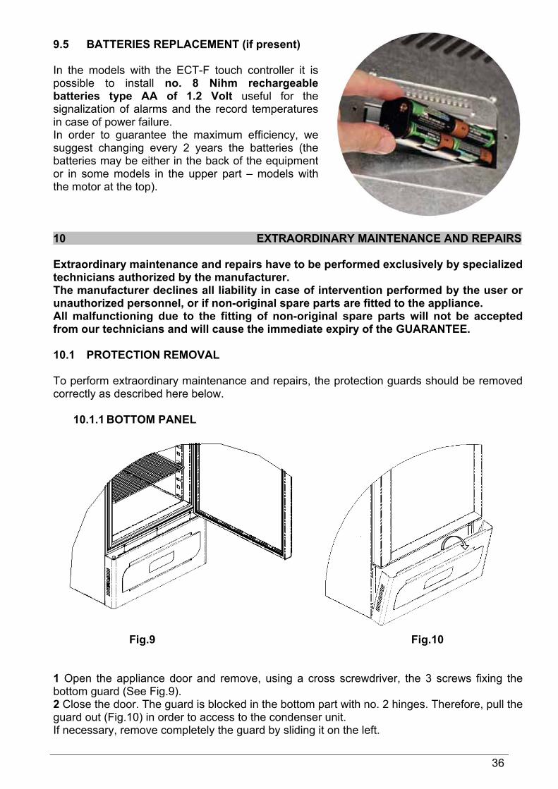
9.5 BATTERIES REPLACEMENT (if present) In the models with the ECT-F touch controller it is possible to install no. 8 Nihm rechargeable batteries type AA of 1.2 Volt useful for the signalization of alarms and the record temperatures in case of power failure. In order to guarantee the maximum efficiency, we suggest changing every 2 years the batteries (the batteries may be either in the back of the equipment or in some models in the upper part – models with the motor at the top). 10 EXTRAORDINARY MAINTENANCE AND REPAIRS Extraordinary maintenance and repairs have to be performed exclusively by specialized technicians authorized by the manufacturer. The manufacturer declines all liability in case of intervention performed by the user or unauthorized personnel, or if non-original spare parts are fitted to the appliance. All malfunctioning due to the fitting of non-original spare parts will not be accepted from our technicians and will cause the immediate expiry of the GUARANTEE. 10.1 PROTECTION REMOVAL To perform extraordinary maintenance and repairs, the protection guards should be removed correctly as described here below.
10.1.1 BOTTOM PANEL
Fig.9 Fig.10 1 Open the appliance door and remove, using a cross screwdriver, the 3 screws fixing the bottom guard (See Fig.9). 2 Close the door. The guard is blocked in the bottom part with no. 2 hinges. Therefore, pull the guard out (Fig.10) in order to access to the condenser unit. If necessary, remove completely the guard by sliding it on the left.

37
10.1.2 TOP FRONTAL PANEL AND ELECTRICAL CIRCUIT OVER
Fig.11 Fig.12 To remove the control panel and have the access to the electric circuit follow the below listed operations: Phase 1 Open the appliance door e remove, using a cross screwdriver, the 3 screws fixing the control panel. Phase 2 The control panel is blocked in the bottom part with 2 hinges, so it must be inclined frontward (Fig.11) and slide it out to the right side (Fig.12). Phase 3 To remove the top cover in model 100-140 it is necessary to unscrew, using a cross screwdriver, the fixing screws of the rear-side guard and push the top cover frontward until its complete unblocking from the fixing hooks. For the other models it is necessary to pull up the top cover to have access the evaporator unit. Repeat the same operations, but inverting the sequence to reposition all the components. 11 DEMOLITION This appliance complies with the 2002/96/EC European Directive. The symbol on the product means that it must not be considered as a domestic waste but it must be handed near the competent authority that recycles electric and electronic appliances. Before scrapping the machine, make it unusable. First of all cut the connecting cable, remove the doors, shelves and drawers so that children can’t go inside the equipment. Do not leave it unattended even for a few days. For further information about management, retrieval and recycle of the product, please contact the local office, the domestic wastes picking service or the distributor. Respect the applicable laws. The refrigerant gas present into the cooling circuit must be extracted by authorized personnel.

38
12 ANNEXES The following documents are attached: - Declaration of conformity with the directive 2006/42/CE - Declaration of conformity with the directive 2006/95/CE - Declaration of conformity with the directive 2004/108/CE - Declaration of conformity with the directive 93/42/CE (applicable only to medical devices) - Production and test sheets - Electrical circuit diagrams 13 DATA PLATES 13.1 DATA PLATES WITH EQUIPMENT CHARACTERISTICS
Only for Medical Devices
1 Name and address of manufacturer 2 Description (C.F.Fiocchetti) 3 Manufacturing year 4 Model (C.F.Fiocchetti) 5 Power tension (V-Ph-Hz) 6 Power absorbance (A/Kw) 7 Refrigerant type 8 Quantity of gas contained (kg) 9 Fuse (A) 10 Serial number 11 Defrost heater power (W) 12 Light power (W) 13 Climatic class - SN (da +10°C a +32°C), N (da +16°C a +32°C) ST (da +18°C a +38°C), T (da +18°C a +43°C), C (da +10°C a +25°C).
1
2
4
5
6
910 6
7
9 1311
3
12

39
13.2 WARNINGS DATA PLATES
Before removing the guard disconnect the equipment from
the mains
Periodic condenser cleaning
Earthling
Change batteries
14 CONSUMABLES
Code
Type/Characteristics
Instrument
Spare/accessory
picture
BAT005
Nihm rechargeable batteries type AA of 1.2 Volt 2.7 Ah
-Ect-f touch -DMLP Digital Monitor
BAT007
Lithium Battery 3V type CR 2032 DISPLAY TFT 7”
ECT-F Touch
BAT004
Lithium battery 3V type CR 1222 ECT-F

40
15 DIAGNOSTIC In the below table are listed the most common faults, the possible causes and the action to be taken.
DESCRIPTION FAILURE / ICON
POSSIBLE CAUSE SOLUTION
Appliance does not switch on
Controller set to “Stand-by” Power failure Faulty controller
-Switch on the controller. -Check plug, socket, fuses, electrical line. -Contact service department.
Equipment is not cooling
Faulty cooling system -Contact service department.
The refrigerator is noisy
Appliance not levelled Moving parts touching guards Screws unscrewed
-Check that the appliance is levelled -Check that fans or piping is not in touch with other parts. -Fix the screws. -Search for vibrations of metallic parts/piping. -If the problem persists, contact service department.
Water or ice stagnation in the drip tray
Drain outlet is clogged Appliance not levelled.
-Clean drain and drain outlet and check that the appliance is levelled. -If the problem persists, contact service department.
Presence of ice on evaporator or on stored goods
Improper use of the equipment Door seals are not efficient
-Limit door openings at the minimum. -Turn off the appliance and disconnect it from mains until a complete defrosting is obtained and turn on the equipment again. -Check door gaskets. -If the problem persists, contact service department.
Refrigerator doesn’t reach the set temperature
Ambient temperature is too high or cooling unit is out ofgas
-Bring ambient temperature to the pre-defined ones (see climatic class on the technical data plate). -Contact service department.
High/Low temperature alarms frequently repeated
Wrong High/Low alarm limits
-Check the set limits with reference to the working setpoint.

41
EVAPORATOR OR LOW EVAP
The evaporator fan is stuck and/or ice has formed on the evaporator Faulty defrost heater
-Check the evaporator fan placed inside the equipment. If the fan works, turn off the unit and disconnect the refrigerator from the mains, as long as the ice won’t have melted completely. Switch on the unit again. -If problem persists, contact service department.
CONDENSER OR HIGH CONDENS
The condenser fan has probably stopped working. The condenser is clogged.
-Check that the equipment is placed in an ambient with a suitable air circulation and with a correct temperature/humidity level (see climatic class on technical data plate). -The air cooling grids should not be covered anyhow (our equipment is not meant to be embedded in other type of furniture). -Check the correct working of the condenser fan and its possible obstruction. -If the above mentioned conditions are absent, disconnect the unit from the mains and switch it on again. -If the problem persists, contact service department.
DIRTY COND The condenser is probably clogged by dirt or dust
-Turn off the equipment, disconnect it from the mains while cleaning the condenser as per given instructions (TUTORIAL menu or Manual). Then, turn on again the equipment. -If the problem persists, contact service department.
COMPRESSOR WORK
Continuous working of compressor for 24hours Too hot ambient temperature Leakage of cooling gas Wrong use of equipment, i.e. too many door openings
-Check that the equipment is placed in an ambient with a suitable air circulation and with a correct temperature/humidity level (see climatic class on technical data plate). -The air cooling grids should not be covered anyhow (our equipment is not meant to be embedded in other type of furniture). -Check the correct working of the condenser fan and its possible obstruction. -If the above mentioned conditions are absent, disconnect the unit from the mains for a few seconds and switch it on again. -If the problem persists, contact service department.
42
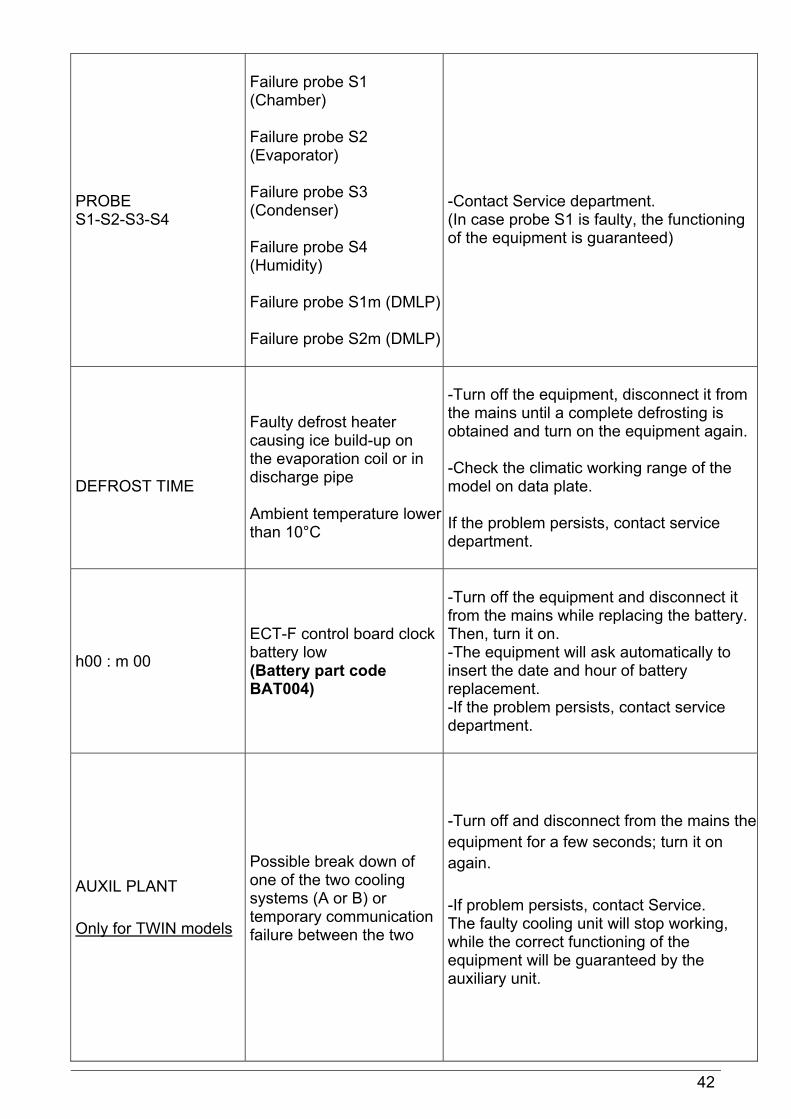
PROBE S1-S2-S3-S4
Failure probe S1 (Chamber) Failure probe S2 (Evaporator) Failure probe S3 (Condenser) Failure probe S4 (Humidity) Failure probe S1m (DMLP) Failure probe S2m (DMLP)
-Contact Service department. (In case probe S1 is faulty, the functioning of the equipment is guaranteed)
DEFROST TIME
Faulty defrost heater causing ice build-up on the evaporation coil or in discharge pipe Ambient temperature lower than 10°C
-Turn off the equipment, disconnect it from the mains until a complete defrosting is obtained and turn on the equipment again. -Check the climatic working range of the model on data plate. If the problem persists, contact service department.
h00 : m 00
ECT-F control board clock battery low (Battery part code BAT004)
-Turn off the equipment and disconnect it from the mains while replacing the battery. Then, turn it on. -The equipment will ask automatically to insert the date and hour of battery replacement. -If the problem persists, contact service department.
AUXIL PLANT Only for TWIN models
Possible break down of one of the two cooling systems (A or B) or temporary communication failure between the two
-Turn off and disconnect from the mains the equipment for a few seconds; turn it on again. -If problem persists, contact Service. The faulty cooling unit will stop working, while the correct functioning of the equipment will be guaranteed by the auxiliary unit.

43
FAULTY BATTERY
The buffer battery is faulty and can’t recharge after the maximum time allowed. (Cod. BAT005)
-Replace the buffer battery. -If problem persists, contact service department.
DOOR SWITCH Possible faulty door micro switch
-Check if the message is correct by opening and closing the door. If the message is wrong, switch off the unit, disconnect it from the mains, and then turn it on again. -If the problem persists, contact service department.
IMPORTANT: In order to be able to arrange a prompt intervention, at the moment of the calling, please provide the model of the appliance the relative serial number that can be found on the data plate placed inside of the appliance or on the present manual.

44 MNL034 Rev. 10-12