use of this material or the information contained therein ... 97.pdf · aberdare cables (pty) ltd ....
TRANSCRIPT

Collection of standards in electronic format (PDF)
1. Copyright
This standard is available to staff members of companies that have subscribed to the complete collection of SANS standards in accordance with a formal copyright agreement. The document may reside on a CENTRAL FILESERVER or INTRANET SYSTEM only. Unless specific permission has been granted, this document MAY NOT be sent or given to staff members from other companies. Doing so would constitute a VIOLATION of SABS copyright rules.
2. Indemnity
Standards South Africa accepts no liability for any damage whatsoever that may result from the use of this material or the information contained therein, irrespective of the cause and quantum thererof.
Click on one of the two boxes
I agree with the above I do not agree

This standard may only be used and printed by approved subscription and freemailing clients of the SABS.
ICS 29.060.20; 29.240.20 ISBN 0-626-13274-6
SABS 97*
*This standard references other standards
Edition 6.1
2001
SOUTH AFRICAN STANDARD
Specification
Electric cables - Impregnated paper-
insulated metal-sheathed cables for rated voltages 3,3/3,3 kV to 19/33 kV (excluding pressure assisted cables)
Consolidated edition incorporating amendment No. 1 : 5 October 2001
Published by
THE SOUTH AFRICAN BUREAU OF STANDARDS Gr 12

This standard may only be used and printed by approved subscription and freemailing clients of the SABS.
SABS 97 Ed. 6.1
Amendments incorporated since the publication of SABS 97:1999
Amdt No. Date Scope
1 2001-10-05 Has been amended to update the definition of "acceptable" and include a requirement for core identification.

This standard may only be used and printed by approved subscription and freemailing clients of the SABS.
ICS 29.060.20; 29.240.20 SABS 97 Ed. 6.1
SOUTH AFRICAN BUREAU OF STANDARDS
SPECIFICATION
ELECTRIC CABLES — IMPREGNATED PAPER-INSULATED METAL-SHEATHED CABLES FOR RATED VOLTAGES 3,3/3,3 kV TO 19/33 kV (EXCLUDING PRESSURE ASSISTED CABLES)
Obtainable from the
South African Bureau of Standards
Private Bag X191 Pretoria
Republic of South Africa
0001
Telephone : (012) 428-7911
Fax : (012) 344-1568 E-mail : [email protected] Website : http://www.sabs.co.za
COPYRIGHT RESERVED
Printed in the Republic of South Africa by the
South African Bureau of Standards

This standard may only be used and printed by approved subscription and freemailing clients of the SABS.
SABS 97 Ed. 6.1
Notice
This standard was approved in accordance with SABS procedures on 15 January 1999. Amendment No. 1 was approved in accordance with SABS procedures on 5 October 2001.
SABS 97
Manufacturers producing impregnated paper-insulated metal-sheathed electric cables to this standard may, under a mark permit issued by the SABS, apply a certification mark to the commodity as evidence to the purchaser that the commodity is being made in accordance with the standard and that compliance with its requirements is ensured by tests and inspections carried out by the SABS.
The mark, which is to be displayed on the product together with the number of the standard, is
illustrated above.
NOTES
1 In terms of the Standards Act, 1993 (Act 29 of 1993), it is a punishable offence for any person other than a mark permit holder to apply a certification mark to a commodity or to refer to the SABS or any of its standards in a manner likely to create the impression that the commodity has been approved by the SABS. Furthermore, no person shall claim or declare that he or any other person complied with an SABS standard unless
a) such claim or declaration is true and accurate in all material respects, and
b) the identity of the person on whose authority such claim or declaration is made, is clear. 2 It is recommended that authorities who wish to incorporate any part of this standard into any legislation in the manner intended by section 31 of the Act consult the SABS regarding the implications.
This standard will be revised when necessary in order to keep abreast of progress. Comment will be
welcome and will be considered when the standard is revised.
Foreword Edition 6.1 cancels and replaces all previous editions.
A vertical line in the margin shows where the text has been modified by amendment No. 1.
Annexes A and B are for information only.
Attention is drawn to the normative references given
in clause 2 of this standard. These references are
indispensable for the application of this standard.
ISBN 0-626-13274-6
ii

This standard may only be used and printed by approved subscription and freemailing clients of the SABS.
SABS 97 Ed. 6.1
Contents Page
Notice . . . ................................................................................................................................................... ii Foreword .................................................................................................................................................... ii Committee . . . ......................................................................................................................................... iv
1 Scope . . . ............................................................................................................................................. 1
2 Normative references .......................................................................................................................... 2
3 Definitions ............................................................................................................................................ 2
4 General requirements . . . ................................................................................................................... 4
5 Inspection and methods of test . . . ................................................................................................... 10
6 Packing and marking . . . ................................................................................................................... 15
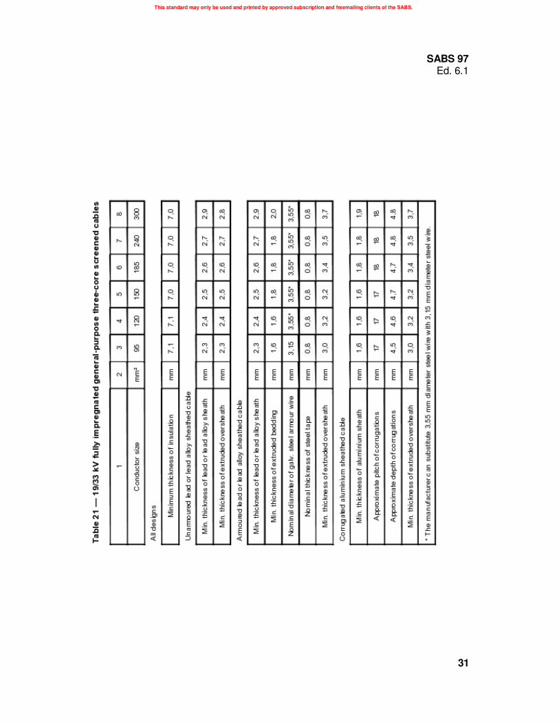
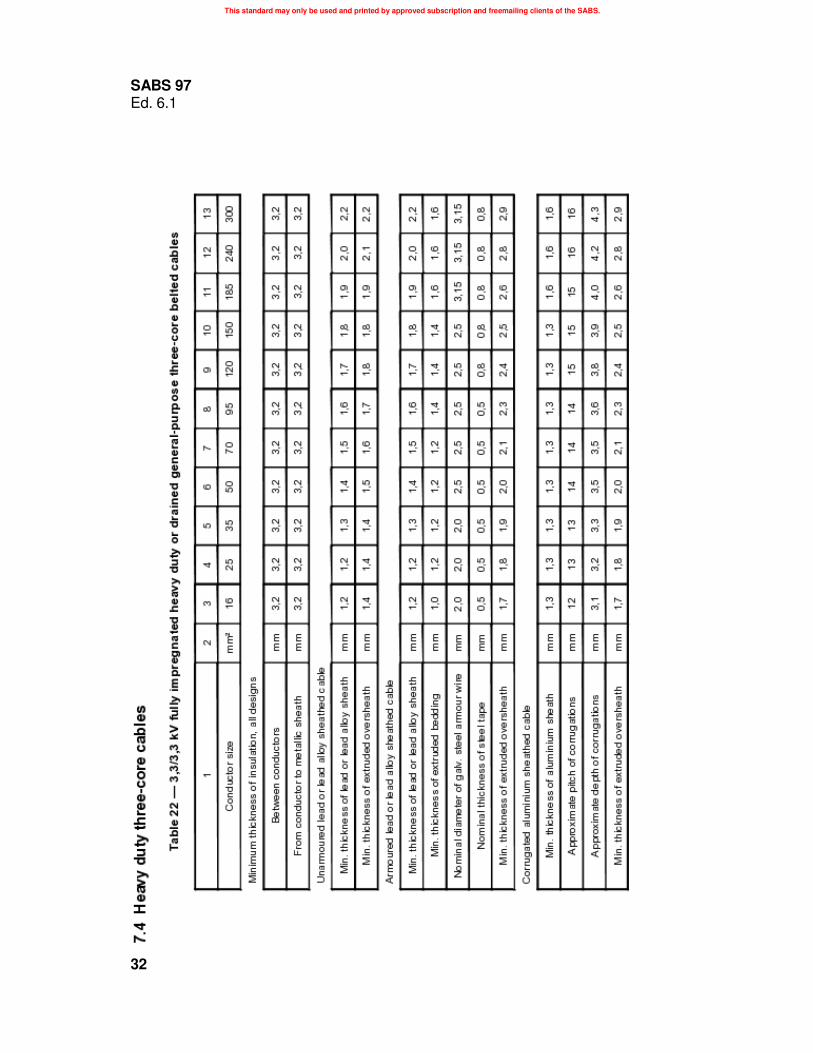
7 Constructional tables . . . ................................................................................................................... 18
Annexes
A Notes to purchasers ........................................................................................................................... 38
B Bibliography . . . ................................................................................................................................. 41
iii

This standard may only be used and printed by approved subscription and freemailing clients of the SABS.
SABS 97 Ed. 6.1
Committee*)
SABS . . . AJ Claasen (Chairman) W Breed (Standards writer) EF Sauer
(Committee clerk)
Aberdare Cables (Pty) Ltd . . . MJ Gibson
African Cables Limited KW Leeburn
Alcon Conductors . . . JH de Lange
Alvern Cables (Pty) Ltd . . . P Wiggin
Association of Electric Cable Manufacturers of South Africa . . . PJ Muller
ATC (Pty) Ltd C Maurer
Chamber of Mines of South Africa . . . AB Johnston
Department of Labour . . . JP Malatse
Department of Public Works . . . CJ Beaurain
Electric Cable Accessories (Pty) Ltd . . . JA Koekemoer
Eskom . . . C Greyling RJ Henderson PA Johnson D Muftic
Iso-Tech Systems CC . . . B Madeley
Kewberg Cables and Braids (Pty) Ltd . . . EHK Naude
National Cables (Pty) Ltd C Youens
Polifin (Pty) Ltd P Rappard
Powermac Cables (Pty) Ltd . . . D MacIntosh
Private . . . M Lang
PVC Compounds (Pty) Ltd . . . JE Harwood
Raytech TD (Pty) Ltd . . . JA Koekemoer
Rosslyn Cables (Pty) Ltd . . . ECJ Barnard
SABS . . . BD Taylor
Safety World (Pty) Ltd . . . S Pohlmann
Sasol Industries (Pty) Ltd - Sastech . . . T Erasmus
Siemens Limited . . . R Marten
Special Cables (Pty) Ltd M Naidu
Spoornet . . . JB Beyers DO Schultz
The Association of Municipal Electricity Undertakings (Southern Africa) . . . JD de Villiers
The Electrical Contractors' Association (South Africa) . . . VAH McDonald
The South African Colliery Engineers' Association AP Eckard KF Reynolds
The South African Institute of Electrical Engineers R Hardie
USKO Limited . . . A Smith
Voltex (Pty) Ltd . . . MJ Freeman
Wire Systems Technology (Pty) Ltd M Kuisis
*) This committee was responsible for the 1999 edition of the standard.
iv

This standard may only be used and printed by approved subscription and freemailing clients of the SABS.
SPECIFICATION SABS 97 Edition 6.1
Electric cables — Impregnated paper-insulated metal-sheathed cables for rated voltages 3,3/3,3 kV to 19/33 kV (excluding pressure assisted
cables)
1 Scope
1.1 This standard specifies the construction, materials, dimensions and test requirements for singlecore and three-core impregnated paper-insulated metal-sheathed cables that have copper or aluminium conductors and lead, lead alloy or corrugated seamless aluminium sheaths, and that have rated voltages from 3,3/3,3 kV up to 19/33 kV. 1.2 The following cable types are covered:
a) fully impregnated, general-purpose, single-core cables of rated voltages 3,8/6,6 kV, 6,35/11 kV, 12,7/22 kV and 19/33 kV; b) fully impregnated heavy duty, or drained general-purpose, single-core cables of rated voltages 3,8/6,6 kV and 6,35/11 kV;
c) fully impregnated, general-purpose, three-core belted cables of rated voltages 3,8/6,6 kV, 6,6/6,6 kV, 6,35/11 kV and 11/11 kV;
d) fully impregnated, general-purpose, three-core screened cables of rated voltages 6,35/11 kV, 12,7/22 kV and 19/33 kV; e) fully impregnated heavy duty, or drained general-purpose, three-core belted cables of rated voltages 3,3/3,3 kV, 3,8/6,6 kV, 6,6/6,6 kV, 6,35/11 kV and 11/11 kV; and f) fully impregnated heavy duty, or drained general-purpose, three-core screened cables of rated voltages 6,35/11 kV.
1.3 Cables that comply with this standard are designed for use at the following maximum operating temperatures:
3,3/3,3 kV, 3,8/6,6 kV and 6,6/6,6 kV : 80 °C
6,35/11 kV, 11/11 kV, 12,7/22 kV and 19/33 kV : 70 °C NOTE - If cables directly buried in the ground operate under continuous load (100 % load factor) at the above maximum operating temperatures, irreversible drying out of the surrounding soil can occur, with an unacceptable progressive increase in the conductor operating temperature. If such operating conditions are anticipated, appropriate precautions should be taken.
1.4 This standard is not applicable to pressure assisted cables.
1

This standard may only be used and printed by approved subscription and freemailing clients of the SABS.
SABS 97 Ed. 6.1
2 Normative references
The following standards contain provisions which, through reference in this text, constitute provisions of this standard. All standards are subject to revision and, since any reference to a standard is deemed to be a reference to the latest edition of that standard, parties to agreements based on this standard are encouraged to take steps to ensure the use of the most recent editions of the standards indicated below. Information on currently valid national and international standards can be obtained from the South African Bureau of Standards.
SABS 1411-1, Materials of insulated electric cables and flexible cords - Part 1: Conductors.
SABS 1411-2, Materials of insulated electric cables and flexible cords - Part 2: Polyvinyl chloride
(PVC).
SABS 1411-6, Materials of insulated electric cables and flexible cords - Part 6: Armour.
SABS 1411-7, Materials of insulated electric cables and flexible cords - Part 7: Polyethylene (PE).
SABS 05, The preservative treatment of timber.
SABS SM 1281-1, Test methods for impregnated paper-insulated electric cables - Part 1: Tests on
insulating and semi-conducting paper.
SABS SM 1281-2, Test methods for impregnated paper-insulated electric cables - Part 2: Tests on
metallic sheaths.
SABS SM 1281-3, Test methods for impregnated paper-insulated electric cables - Part 3: Tests on
finished cable.
SABS SM 1283, Test methods for armouring of insulated electric cables.
SABS IEC 60811-1-1, Common test methods for insulating and sheathing materials of electric cables - Part 1: Methods for general application - Section 1: Measurement of thickness and overall dimensions - Tests for determining the mechanical properties.
3 Definitions For the purposes of this standard, the following definitions and those given in SABS 1411-1,
SABS 1411-2, SABS 1411-6 and SABS 1411-7 apply. In the case of conflicting requirements, the
definitions given below take precedence.
| 3.1 acceptable: Acceptable to the authority administering this standard or to the parties concluding
| the purchase contract, as relevant. Amdt 1, Oct. 2001
3.2 approximate value: A value that is neither guaranteed nor checked; it is used, for example, for the
calculation of dimensional values.
3.3 armouring: Mechanical protection for a lead sheathed cable, comprising one or two layers of
galvanized steel wires or two layers of steel tape, or for a single-core cable, a layer of aluminium wires.
3.4 bedding: A layer (or layers) of material applied between the lead sheath and the armouring of
a cable.
2

This standard may only be used and printed by approved subscription and freemailing clients of the SABS.
SABS 97 Ed. 6.1
3.5 belted cable: A three-core cable, in which additional insulation (the belt insulation) is applied over
the laid-up core assembly.
3.6 braid (braiding): A plaited protective covering of impregnated fibrous materials, that can
constitute the whole, or the outer portion, of the serving.
3.7 core: An insulated conductor.
3.8 drained cable: A mass-impregnated cable from which surplus impregnating compound has
been removed during manufacture.
3.9 filler: A material placed in the interstices of the cores of a three-core cable.
3.10 fully impregnated non-drained cable: A mass-impregnated cable from which surplus
impregnating compound has not been removed during manufacture.
3.11 intercalated tape: One of two tapes, each so applied helically with a defined overlap that,
should one tape break, the other tape will prevent the broken tape from unravelling.
3.12 metal sheath: An extruded layer of lead or lead alloy, or an extruded and corrugated
aluminium tube applied over a core or laid-up core assembly.
3.13 rated voltage: The voltage at which the cable is designed to operate, expressed as two values U0 /U
where U0 is the power frequency r.m.s. voltage between phase and neutral or earth, and U is the power
frequency r.m.s. voltage between phases.
3.14 routine test (R): A test conducted at the manufacturer's works on all cable lengths during
manufacture or in the finished state, as appropriate.
3.15 sample test (S): A test conducted on a regular basis at the manufacturer's works or on
representative samples taken by the manufacturer, or as requested by the purchaser at the time of
enquiry or order.
3.16 screened cable: A cable in which, in order to ensure a radial electric field surrounding the conductor, each core is individually screened by a non-magnetic conducting tape, foil or film that is in electrical contact with the metal sheath of the cable and, in the case of three-core cables, in direct electrical contact with the screens of the other two cores.
3.17 separator: A close lapping of compounded fibrous material applied between the two layers of
armour wires of double-wire armoured cables.
3.18 serving: A layer (or layers) of material applied helically or as a braid, or a layer of extruded
material that provides outer protection for the cable.
3.19 type test (T): A test conducted before a type of cable covered by this standard is supplied on a general commercial basis, in order to demonstrate that the cable has the necessary performance characteristics for the intended application. NOTE - The test is of such a nature that, after it has been successfully completed, it need not be repeated unless changes are made in the cable materials or design that might change the performance characteristics of the cable.
3

This standard may only be used and printed by approved subscription and freemailing clients of the SABS.
SABS 97 Ed. 6.1
4 General requirements
4.1 Cable operating voltage
The operating voltages for earthed systems (defined by the relationship U0 /U recognized for the purposes of this standard) are 3,8/6,6 kV, 6,35/11 kV, 12,7/22 kV and 19/33 kV.
Cables for unearthed systems are denoted by the voltage between phases (U/U ) only, for example
3,3/3,3 kV, 6,6/6,6 kV and 11/11 kV.
4.2 Materials and construction
4.2.1 Conductors
Conductors shall comply with the requirements for class 2 conductors of SABS 1411-1.
Conductor profiles for the various voltages shall be as given in table 1.
Table 1 — Conductor profiles
1 2 3 4 5 6 7 8 9 10 11 12
System Conductor size
voltage mm2
kV 16 25 35 50 70 95 120 150 185 240 300
3,3 & 6,6 C C/S C/S C/S C/S C/S C/S C/S C/S C/S C/S
11 C C C/S C/S C/S C/S C/S C/S C/S C/S
22 C C C C/S C/S C/S C/S C/S
33 C C C C/O C/O C/O
C: Circular only
C/S: Circular or shaped
C/O: Circular or oval
4.2.2 Insulation
4.2.2.1 Composition
The insulation shall consist of paper, impregnated with a suitable non-draining insulating compound.
4.2.2.2 Paper
The paper component of the impregnated paper insulation shall be of electrical grade, of uniform dispersion and thickness, and free from bunched or imperfectly pulped fibres, thin areas and pinholes. It shall also be free from size, mineral fillers, and metal or other deleterious particles.
When determined in accordance with 5.9, the mass of the ash residue shall not exceed 1,5 % of the
mass of the dry paper.
4

This standard may only be used and printed by approved subscription and freemailing clients of the SABS.
SABS 97 Ed. 6.1
When determined in accordance with 5.10, the tensile strength of the paper shall be at least 660 N per millimetre of thickness per 15 mm of width, and the elongation at break shall be at least 1,0 %. The thickness of any paper tape shall not exceed 0,14 mm.
When determined in accordance with 5.11, the pH value of the water extracted from the insulating
paper shall be between 6,5 and 6,8, and the conductivity of the water shall not exceed 0,005 S/m.
4.2.2.3 Application of paper
The paper shall be applied in the form of tapes laid helically. When applied in the same direction, successive layers shall break joint so as to form a reasonably smooth and compact covering of uniform thickness. The registration shall be generally between 60/40 and 80/20. It is permissible, however, to have a group of three coincident gaps in adjacent tapes but there shall not be more than two such groups in the insulation thickness.
4.2.2.4 Insulation thickness
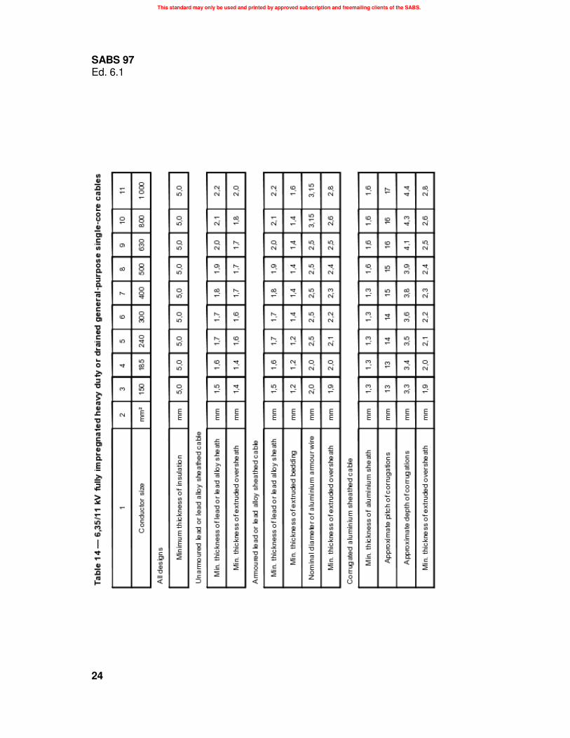
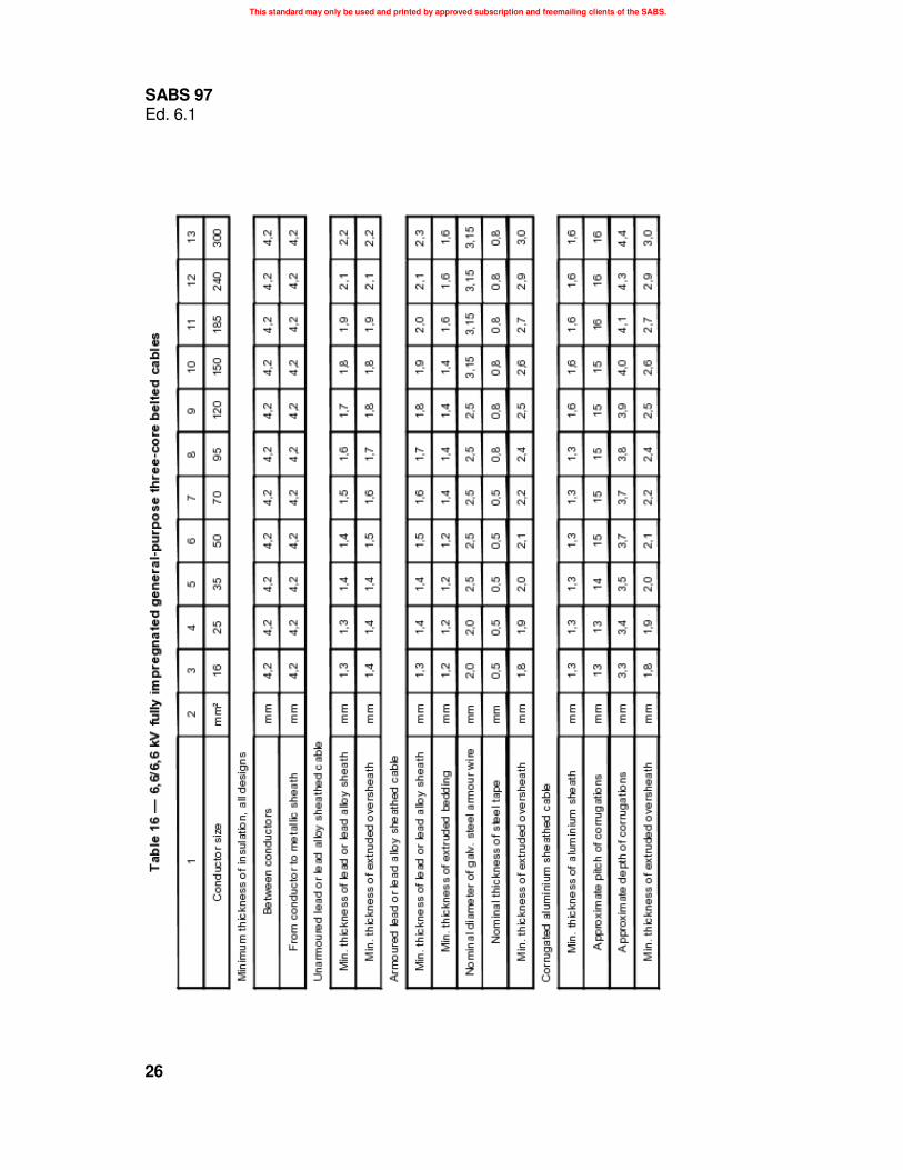
When determined in accordance with 5.4.1, the thickness of the insulation shall be not less than the minimum value given in the appropriate constructional table (see clause 7).
When the thickness of the insulation is being determined, a conductor screen of semi-conducting
paper tape, applied in accordance with 4.2.3.1, can be considered to be part of the insulation.
4.2.2.5 Core identification |
|
The cores of three-core cables shall be identified by the numbers 1, 2 and 3 printed at frequent | intervals on the outer layer of the paper tape. Amdt 1, Oct. 2001 |
4.2.3 Screening 4.2.3.1 Conductor screen
Cables of rated voltages 12,7/22 kV and 19/33 kV shall have a conductor screen immediately over and in contact with the conductor. The conductor screen shall consist of two semi-conducting paper tapes, applied helically in the same direction, to provide a total nominal thickness not exceeding 0,28 mm.
The second tape shall cover the gap between the helical windings of the first tape.
This construction shall also be used for 6,35/11 kV and 11/11 kV cables, if so required (see annex A).
4.2.3.2 Core screens for screened cables
Cables intended for operation on 11 kV, 22 kV and 33 kV systems shall have a core screen. The core
screens for single-core and three-core screened cables shall be as follows:
a) single-core cables: a non-magnetic conducting foil, tape or metallized paper tape shall be applied helically over the insulation. A copper-woven or aluminium-woven fabric tape can be applied helically over the core screen.
b) three-core cables: the final tape applied to each core shall be a non-magnetic conducting foil,
tape or metallized paper tape applied helically over the insulation.
5
This standard may only be used and printed by approved subscription and freemailing clients of the SABS.
SABS 97 Ed. 6.1 The application of the screen(s) shall not impair impregnation, shall ensure electrical continuity and shall not result in free metal particles. The screening shall be free from tears.
4.2.4 Laying up of three-core cables
4.2.4.1 General
The cores of three-core cables shall be laid up together with an appropriate right-hand lay, using paper, jute or other suitable fillers, to form a substantially circular assembly.
4.2.4.2 Belted cables
Belt papers, that comply with the requirements of 4.2.2.2, shall be applied, in accordance with 4.2.2.3, to the laid-up core assembly of a belted cable. Belted cables of rated voltages 6,35/11 kV or 11/11 kV shall have an overall screen comprising a semi-conducting paper tape or tapes, each of nominal thickness not exceeding 0,14 mm, applied helically with an overlap over the belt insulation.
4.2.4.3 Screened cables
The laid-up cores of screened cables shall be bound together with a helically applied, copper-woven or aluminium-woven fabric tape, that effectively bonds together the individual conducting core screens and bonds each screen to the metallic sheath.
4.2.5 Impregnation The impregnant and the impregnation process shall be such that the completed cable is suitable for the condition of service up to the maximum recommended operating temperature. The process of impregnation and the application of the metallic sheath shall be such that the part of the cable within the sheath is substantially free from gas, moisture and other deleterious substances.
4.2.6 Manufacturer's identification Except in the case of cables that have an extruded polymeric oversheath, an identification tape that bears the information required in terms of 6.2.1 shall be laid under the metal sheath throughout the length of the cable.
4.2.7 Metal sheaths
4.2.7.1 General
The metal sheath shall be either lead, lead alloy or corrugated seamless aluminium, as required (see annex A). The sheath shall be in the form of a continuous tube that is impervious to moisture and free from all defects.
4.2.7.2 Lead or lead alloy sheaths Lead sheaths for all single-core and unarmoured three-core cables shall be lead alloy E. Pure lead may only be used on armoured three-core cables. When determined in accordance with 5.6, the composition of lead or lead alloy sheaths shall comply with the values given in the appropriate column of table 2. The malleability of a sheath shall be such that, when the sheath is tested in accordance with 5.7, it does not split or crack when the internal diameter of the expanded section reaches 150 % of the original internal diameter.
6

This standard may only be used and printed by approved subscription and freemailing clients of the SABS.
SABS 97 Ed. 6.1
Table 2 — Composition of lead and lead alloy sheaths
1
Element
Antimony Tin Copper
Bismuth Tellurium Silver
Zinc Total other elements
(not included above)
Lead
4.2.7.3 Corrugated aluminium sheaths
2 3 4 5
Content %
Material
Lead alloy E Lead
Min. Max. Min. Max.
0,15 0,25 - 0,20 0,35 0,45 - 0,10 - 0,06 - 0,06
- 0,05 - 0,05 - 0,005 - 0,010 - 0,005 - 0,010
- 0,002 - 0,002
- 0,01 - 0,01
remainder 99,7 -
The aluminium used shall be electrical grade, of purity not less than 99,5 %. The tube shall be extruded oversize and corrugated by rolling, to produce discrete rings, the inner surface of which is a reasonably close fit over the cable core or laid-up core assembly. Approximate dimensions of the discrete ring corrugations are given in the constructional tables. Additional impregnating compound shall be applied to the cable under the sheath, so that after completion of the corrugating process, the space within the corrugations is approximately 70 % filled.
4.2.7.4 Thickness of metal sheath
When measured in accordance with 5.4.2.1, the thickness of the metal sheath shall be not less than the minimum value given in the appropriate constructional table.
4.2.8 Bedding under armour 4.2.8.1 Lapped bedding
Bedding applied to a lead or lead alloy sheath shall comprise one or more layers of suitably impregnated and compounded fibrous material or plastics tape, and shall be of thickness approximately 1,5 mm after application of the armour.
Bedding materials can be impregnated with bituminous compounds or other preservative materials.
4.2.8.2 Extruded polymeric bedding
When an extruded bedding is applied over a lead or lead alloy sheath, it shall be of
a) PVC type B in accordance with SABS 1411-2, or
b) polyethylene type PS1 in accordance with SABS 1411-7, or
c) other acceptable material.
7

This standard may only be used and printed by approved subscription and freemailing clients of the SABS.
SABS 97 Ed. 6.1
When measured in accordance with 5.4.2.2, the thickness of the extruded bedding shall be not less
than the minimum value given in the appropriate constructional tables.
4.2.9 Armour
4.2.9.1 General
The armour of single-core cables that will be used in a.c. circuits should be of non-magnetic material, usually a single layer of aluminium wires. Armour for three-core cables shall be either galvanized steel tape or galvanized steel wires.
4.2.9.2 Double steel tape armour (DSTA)
Two layers of galvanized steel tape, that comply with the requirements of SABS 1411-6, shall be applied helically, using a left-hand lay, with a gap spacing for each tape that does not exceed 50 % of the width of the tape. The outer tape shall cover the inner tape on each side of the gap by at least 15 % of the width of the tape. When measured in accordance with 5.4.2.3, the nominal thickness of each tape shall be as given in the appropriate constructional table.
4.2.9.3 Wire armour
Galvanized steel wires or aluminium wires of purity not less than 99,5 % and that comply with the requirements of SABS 1411-6, shall be applied helically with a left-hand lay of pitch not more than 12 times the pitch circle diameter. Where double wire armour is required, the two layers shall have opposite directions of lay, and there shall be a separator of compounded fibrous material between the two layers. A galvanized steel tape, of width at least 10 mm and of thickness at least 0,3 mm, can be used as a binder over the galvanized steel wires.
When measured in accordance with 5.4.2.3, the nominal diameter of the armour wires shall be as
given in the appropriate constructional table.
4.2.9.4 Joints
Any joints in steel tapes or wires that are necessary in the armouring process shall be made in an acceptable workmanlike manner and shall not have sharp edges or protruding points. When multiple joints in armour wires are necessary, such multiple joints shall be acceptably staggered.
4.2.10 Serving and oversheath
4.2.10.1 Fibrous serving over armour
Fibrous serving shall be of thickness approximately 2 mm and shall be made up of a suitable number of layers of compounded fibrous materials. If so required (see annex A), a braid may be used for a part of or for the whole of the serving.
Before final drumming, the surface of each cable that is served with impregnated fibrous materials and
bituminous compound shall be coated with limewash or other suitable material to prevent adhesion
between adjacent turns on the drum.
4.2.10.2 Extruded polymeric oversheath
Extruded polymeric oversheaths should be black and shall be of
a) PVC type S2 in accordance with SABS 1411-2, or
8

This standard may only be used and printed by approved subscription and freemailing clients of the SABS.
SABS 97 Ed. 6.1
b) polyethylene type PS2 in accordance with SABS 1411-7, or
c) other acceptable material. When measured in accordance with 5.4.2.2, the thickness of the extruded oversheath shall be not less than the minimum value given in the appropriate constructional table. NOTE - Cables shall bear the marking required in terms of 6.2.1. Cables sheathed with polyethylene or other readily ignitable materials are not recommended for installation in high fire risk areas, unless suitably protected.
4.2.10.3 Drainage
When a drained cable is tested in accordance with 5.12, it shall not exude a compound volume that
exceeds 1,5 % of the volume enclosed by the lead sheath.
4.3 Electrical requirements 4.3.1 Conductor resistance
When a cable is tested in accordance with 5.5, the d.c. resistance of each conductor shall not exceed the
appropriate maximum value given in SABS 1411-1.
4.3.2 Voltage withstand
When a cable is tested in accordance with 5.8, each core of the cable shall withstand, without
breakdown of the insulation, the appropriate test voltage given in table 3.
Table 3 — Test voltages
Values in kilovolts
1
Cable system voltage
3,3 6,6
11 22 33
2 3 4
Test voltage
Belted cables
Between Between any conductor conductors and the sheath earthed or unearthed Earthed Unearthed
10 - 10 17 10 17 25 15 25 - - - - - -
5 6
Single-core cables and screened cables
Between any conductor and the screen or sheath
Earthed Unearthed
- - 10 17 15 25 30 - 45 -
4.3.3 Tangent of the dielectric loss angle (ionization test) When a 22 kV or a 33 kV cable is tested in accordance with 5.13, the tangent of the dielectric loss angle (tan δ) at 0,5 U0 shall not exceed 0,006 and the maximum permissible rise in tan δ with voltage
a) from 0,5 U0 to 1,25 U0 shall not exceed 0,004, and
b) from 1,25 U0 to 2,0 U0 shall not exceed 0,008.
9

This standard may only be used and printed by approved subscription and freemailing clients of the SABS.
SABS 97 Ed. 6.1
4.3.4 Bending 4.3.4.1 When a cable is tested in accordance with 5.14, there shall be no electrical breakdown of the insulation. Any extruded polymeric oversheath shall be free from splits, the armour shall not be noticeably displaced and the metal sheath shall be free from splits and cracks.
4.3.4.2 The number of papers in the length of cable tested in accordance with 5.14, that contain longitudinal or edge tears of length exceeding 6 mm, shall not exceed the following:
Belt papers Core papers
– for 3,3 kV cables No limit 50 %
– for 6,6 kV cables 50 % 25 %
– for 11 kV cables 20 % 10 %
– for 22 kV cables N/A 5 %
– for 33 kV cables N/A 5 %
The percentages given for core papers are per core in the case of three-core cables. For the purposes of this test, conductor screening papers shall be considered together with the insulating papers. Belt screening papers shall not contain any tear that extends across their complete width.
At no point throughout the insulation shall there be more than three coincident tears of any length in adjacent papers.
4.3.4.3 When the conductor is examined visually after the bending test, impregnating compound shall be seen to have penetrated the interstices of stranded conductors.
4.3.5 Performance of screened cables When a specimen of screened cable is subjected to the load cycling, impulse voltage and four-hour high-voltage tests given in 5.15, 5.16 and 5.17 respectively, satisfactory performance shall be indicated by
a) a graphical representation of the hot and cold dielectric loss angle measurements that shows no progressive increase in either set of values,
b) the ability to withstand the impulse voltage test without failure, and
c) the ability of the same specimen, or a fresh specimen of cable, to withstand the four-hour high- voltage a.c. withstand test.
5 Inspection and methods of test 5.1 Inspection Visually inspect each drum of cable in the sample for compliance with all the relevant requirements of this standard for which tests to assess compliance are not given in 5.4 to 5.17 (inclusive).
5.2 Tests For convenience, the properties to be tested, the test category, the test methods and the subclause that gives the requirements are listed in table 4.
10

This standard may only be used and printed by approved subscription and freemailing clients of the SABS.
SABS 97 Ed. 6.1
Table 4 — List of tests
1 2
Cable component Test property
Conductor Construction
Insulation Thickness
Paper Ash residue Tensile strength pH and conductivity
of water extract
Laid-up cores Manufacturer's ID
Lead sheath Composition (lead or lead alloy E) Belling
Thickness
Aluminium sheath Dimensions Thickness
Bedding (extruded) Composition/ properties Thickness
Armour (tape) Thickness and properties
Armour (wire) Diameter and properties
Oversheath (extruded) Composition/ properties Thickness
Finished cable Marking Conductor resistance Voltage withstand Ionization test Bending Load cycling Impulse voltage Four-hour voltage Drainage
3
Test category
S
S
S S
S*
R
S* S S
S S
S
S
S
S
S
S
R R R S T T T T T
4 5
Requirement Test method
subclause
SABS 1411-1 4.2.1
SABS SM 1281-1 4.2.2.4
SABS SM 1281-1 4.2.2.2 SABS SM 1281-1 4.2.2.2
SABS SM 1281-1 4.2.2.2
Visual examination 4.2.6
SABS SM 1281-2 4.2.7.2 SABS SM 1281-2 4.2.7.2 SABS SM 1281-2 4.2.7.4
SABS SM 1281-2 4.2.7.3 SABS SM 1281-2 4.2.7.4
SABS 1411-2 and 4.2.8.2 SABS 1411-7 4.2.8.2 SABS IEC 60811-1-1 4.2.8.2
SABS SM 1283 4.2.9.2 SABS 1411-6
SABS SM 1283 4.2.9.3 SABS 1411-6
SABS 1411-2 and 4.2.10.2 SABS 1411-7 4.2.10.2 SABS IEC 60811-1-1 4.2.10.2
Visual examination 6.2.1 SABS SM 1282-1 4.3.1 SABS SM 1281-3 4.3.2 SABS SM 1281-3 4.3.3 SABS SM 1281-3 4.3.4 SABS SM 1281-3 4.3.5 (a) SABS SM 1281-3 4.3.5 (b) SABS SM 1281-3 4.3.5 (c) SABS SM 1281-3 4.2.10.3
* Certified values from the material supplier may be regarded as acceptable.
NOTES
1 In column 3 of this table, a code letter is given that identifies the tests as suitable for use as routine tests (R), sample tests (S) or type tests (T), but compliance with the requirements of this standard can only be fully determined from the results of tests carried out on samples of completed cable(s), using all the test methods given and a sampling procedure agreed upon (see annex A). During production control, a manufacturer may use any test method that he deems necessary to ensure compliance with this standard but, in cases of dispute, only the appropriate standard test methods should be used.
2 In the administration of the certification mark scheme, the frequency of testing required and the test methods to be used are the subject of a separate agreement between the Council of the South African Bureau of Standards and the mark permit holder.
11

This standard may only be used and printed by approved subscription and freemailing clients of the SABS.
SABS 97 Ed. 6.1
5.3 Conditions of test The following conditions of test apply:
a) unless otherwise stated in the method of test, all tests are carried out at ambient temperature and
pressure; and
b) unless otherwise required in the method of test, the frequency of the alternating test voltage used
is approximately 50 Hz, and the waveform is substantially sinusoidal.
5.4 Dimensions
5.4.1 Thickness of insulation Use SABS SM 1281-1. Either the diameter tape method (1.3) or the deadweight micrometer method (1.4) can be used for the measurement of core insulation thickness, but the deadweight micrometer method shall be used for measuring the thickness of belt insulation. In cases of dispute, the deadweight micrometer individual tape method (1.4.1) shall be used.
5.4.2 Other dimensions
5.4.2.1 Thickness of metal sheath
Use the methods given in SABS SM 1281-2 to determine the thickness of a lead or lead alloy sheath or the thickness, pitch and depth of corrugations of an aluminium sheath.
5.4.2.2 Thickness of extruded bedding and oversheath
Use the methods given in SABS IEC 60811-1-1.
5.4.2.3 Diameter of armour wire and thickness of steel tape
Use the methods given in SABS SM 1283.
5.5 Conductor resistance Use the method given in SABS SM 1282-1.
5.6 Composition of lead or lead alloy sheaths Use the method given in SABS SM 1281-2.
5.7 Belling test for lead or lead alloy sheaths Use the method given in SABS SM 1281-2.
5.8 Voltage withstand test Use the method given in SABS SM 1281-3. Apply, for 15 min, the appropriate test voltage given in
table 3.
12

This standard may only be used and printed by approved subscription and freemailing clients of the SABS.
SABS 97 Ed. 6.1
5.9 Ash residue of insulating paper Use the method given in SABS SM 1281-1.
5.10 Tensile strength of insulating paper Use the method given in SABS SM 1281-1.
5.11 Hydrogen ion concentration (pH) and conductivity of water extract from insulating and semi-conducting paper Use the method given in SABS SM 1281-1.
5.12 Drainage test Use the method given in SABS SM 1281-3. The sample test, 9.1.1.1, is intended for use by the manufacturer as a check during production and it is not a mandatory test. Test 9.1.1.2 is part of the type test procedure. Either test need only be conducted on drained cables.
Use a test temperature of 80 °C for 3,3 kV and 6,6 kV cables and 70 °C for 11 kV cables.
5.13 Ionization test on screened cables Use the method given in SABS SM 1281-3.
5.14 Bending test
Bend the cable specimen, using the method given in SABS SM 1281-3, on a test cylinder of the appropriate diameter given in table 5.
Table 5 — Test cylinder diameter
1 2 3
Cable system Test cylinder diameter voltage
Single-core Three-core kV cables cables
11 15(D + d) 12(D + d) 22 18(D + d) 15(D + d) 33 21(D + d) 18(D + d)
where D is the measured diameter over the metal sheath, in millimetres; and d is the measured diameter of a conductor, in millimetres (for shaped or oval conductor, d is the measured perimeter divided by π).
After bending the cable specimen, apply, for 10 min, the appropriate alternating voltage given in table 6.
13

This standard may only be used and printed by approved subscription and freemailing clients of the SABS.
SABS 97 Ed. 6.1
Table 6 — Bending test voltages
Values in kilovolts
1 Cable
system voltage
3,3 6,6
11 22 33
2 3 4
Test voltage
Belted cables
Between Between any conductor conductors, and the sheath earthed or unearthed Earthed Unearthed
15 - 15 25 15 25 35 20 35 - - - - - -
5 6
Single-core cables and screened cables
Between any conductor and the screen or sheath
Earthed Unearthed
- - 15 25 20 35 35 - 45 -
After the bending test, examine the test specimen in accordance with SABS SM 1281-3, and check for
compliance with 4.3.4.
5.15 Load cycling test Use the method given in SABS SM 1281-3. Subject the test installation to thermal load cycles, each consisting of 6 h with conductor current loading (heating), followed by 18 h without current loading (cooling). During the last 3 h of each conductor heating period, adjust the loading current, if necessary, to maintain the conductor at a temperature between 70 °C and 75 °C.
During the load cycles, apply, continuously, a test voltage at normal power frequency of r.m.s. value
equal to 1,33 times the normal working voltage of the cable.
Present the hot and cold measurements of dielectric loss angle in graphical form. Carry out the test for a
maximum of 250 load cycles, but if the measured values of tan delta are stable after 100 cycles, with no
indication of a progressive increase in either value, the test can be terminated.
5.16 Impulse voltage test Use the method given in SABS SM 1281-3. Carry out the impulse voltage test with the conductor(s) maintained at a temperature between 65 °C and 70 °C. Use a peak value of impulse voltage as given in table 7.
14

This standard may only be used and printed by approved subscription and freemailing clients of the SABS.
SABS 97 Ed. 6.1
Table 7 — Impulse voltage
Values in kilovolts
1 2
Cable system Impulse voltage voltage
11 95 22 150 33 200
By subjecting the installation to the voltage withstand test given in 5.8, check whether the cable has
successfully withstood the impulse voltage test.
5.17 Four-hour high-voltage a.c. withstand test The cable that has successfully withstood the impulse voltage test given in 5.16, may be subjected to the four-hour high-voltage a.c. withstand test in accordance with SABS SM 1281-3. If, however, a failure should result, the test shall be repeated on a new specimen of cable and only the results of the test on the new specimen shall be included in the type approval test report.
The cable shall withstand, without failure, for a period of 4 h at ambient temperature, the appropriate voltage as given in table 8.
Table 8 — Four hours withstand voltage
Values in kilovolts
1 2
Cable system 4 h withstand voltage voltage
11 19 22 38 33 57
6 Packing and marking
6.1 Packing
6.1.1 Drums Unless otherwise required (see annex A), cables shall be wound onto wooden drums. The moisture content of the wood shall not exceed 20 %. When wooden drums are required to be resistant to biological attack, the wood shall be impregnated (by pressure or in a hot/cold tank), in accordance with SABS 05, with a class C preservative or with chromated copper arsenate.
15
This standard may only be used and printed by approved subscription and freemailing clients of the SABS.
SABS 97 Ed. 6.1
6.1.2 Drum barrels
Unless otherwise required (see annex A), the diameter of the drum barrel shall be at least
- for 3,3 kV to 11 kV cables : single-core : 25D three-core : 15D
– for 22 kV and 33 kV cables : single-core : 30D
three-core : 20D
where D is the nominal overall diameter of the cable to be wound onto the drum.
6.1.3 Sealing Before the cable is wound onto the drum, each end of the cable shall be sealed by means of a metal cap plumbed onto the metal sheath or by other acceptable means, to prevent the ingress of air or moisture.
The outer end of the cable shall be secured to the drum and the inner end shall be protected in an acceptable manner against mechanical damage.
6.2 Marking 6.2.1 Marking of cables
6.2.1.1 Cables shall bear the following information:
a) the manufacturer's name or trademark (or both);
b) the year of manufacture; and
c) the operating voltage (U0 /U or U/U), in kilovolts, for which the cable has been designed.
6.2.1.2 In the case of a cable that has an extruded polymeric oversheath, the information shall be legibly printed, indented or embossed on one or more lines along the oversheath, in letters and numerals that are upright characters of height not more than 13 mm and not less than 3 mm. The gap between the end of one legend and the beginning of the next shall not exceed 300 mm.
6.2.1.3 In the case of other cables, the information shall be given on the marker tape (see 4.2.6).
6.2.2 Marking of drums
A flange of each drum of cable shall bear the following information in legible and indelible marking. The marking can be painted, gouged or branded on the flange. The information given in (a) to (e) below can, however, be detailed on a durable label firmly attached to the flange:
a) the manufacturer's name or trademark (or both);
b) the rated voltage, the conductor size, and whether copper or aluminium, the number of cores, whether general purpose, heavy duty, belted or screened, whether lead, lead alloy E or aluminium sheathed and (if applicable) whether steel tape or wire armoured;
16

This standard may only be used and printed by approved subscription and freemailing clients of the SABS.
SABS 97 Ed. 6.1
c) the words "DRAINED CABLE", if applicable;
d) the length, in metres;
e) the year of manufacture;
f) the gross mass, in kilograms, of cable plus drum;
g) the instruction, "NOT TO BE LAID FLAT";
h) the serial number or other identification;
i) an arrow with the words "ROLL THIS WAY", to indicate the direction in which the drum is to be rolled in order to prevent the cable from unwinding;
j) if the wood from which the drum was made has been treated in accordance with 6.1.1, a 50 mm high capital letter "T", surrounded by a circle of outside diameter 65 mm.
17

This standard may only be used and printed by approved subscription and freemailing clients of the SABS.
SABS 97 Ed. 6.1
18

This standard may only be used and printed by approved subscription and freemailing clients of the SABS.
SABS 97 Ed. 6.1
19

This standard may only be used and printed by approved subscription and freemailing clients of the SABS.
SABS 97 Ed. 6.1
20

This standard may only be used and printed by approved subscription and freemailing clients of the SABS.
SABS 97 Ed. 6.1
21

This standard may only be used and printed by approved subscription and freemailing clients of the SABS.
SABS 97 Ed. 6.1
22

This standard may only be used and printed by approved subscription and freemailing clients of the SABS.
SABS 97 Ed. 6.1
23
This standard may only be used and printed by approved subscription and freemailing clients of the SABS.
SABS 97 Ed. 6.1
24

This standard may only be used and printed by approved subscription and freemailing clients of the SABS.
SABS 97 Ed. 6.1
25
This standard may only be used and printed by approved subscription and freemailing clients of the SABS.
SABS 97 Ed. 6.1
26

This standard may only be used and printed by approved subscription and freemailing clients of the SABS.
SABS 97 Ed. 6.1
27

This standard may only be used and printed by approved subscription and freemailing clients of the SABS.
SABS 97 Ed. 6.1
28

This standard may only be used and printed by approved subscription and freemailing clients of the SABS.
SABS 97 Ed. 6.1
29

This standard may only be used and printed by approved subscription and freemailing clients of the SABS.
SABS 97 Ed. 6.1
30
This standard may only be used and printed by approved subscription and freemailing clients of the SABS.
SABS 97 Ed. 6.1
31
This standard may only be used and printed by approved subscription and freemailing clients of the SABS.
SABS 97 Ed. 6.1
32

This standard may only be used and printed by approved subscription and freemailing clients of the SABS.
SABS 97 Ed. 6.1
33

This standard may only be used and printed by approved subscription and freemailing clients of the SABS.
SABS 97 Ed. 6.1
34

This standard may only be used and printed by approved subscription and freemailing clients of the SABS.
SABS 97 Ed. 6.1
35

This standard may only be used and printed by approved subscription and freemailing clients of the SABS.
SABS 97 Ed. 6.1
36

This standard may only be used and printed by approved subscription and freemailing clients of the SABS.
SABS 97 Ed. 6.1
37

This standard may only be used and printed by approved subscription and freemailing clients of the SABS.
SABS 97 Ed. 6.1
Annex A (informative)
Notes to purchasers
A.1 Points to be considered by the purchaser
A.1.1 Cables with stranded aluminium and stranded copper conductors of the same nominal crosssectional area and type will have comparable dimensions. However, it should be noted that under the same conditions of service, the current-carrying capacity of the aluminium conductor cable will be approximately 78 % of that of the copper conductor cable.
A.1.2 The short-circuit rating of a cable is determined by the fault duration and the maximum permissible conductor temperature under fault conditions. Cables manufactured in accordance with this standard have the following maximum permissible conductor temperatures under fault conditions:
- with soldered lugs and ferrules : 160 °C
– with crimped or welded lugs and ferrules : 250 °C
A.1.3 Cables manufactured in accordance with this standard and that are to be installed under
conditions where they will be subject to vibration should have metal sheaths of lead alloy E or of
aluminium.
A.1.4 Cables that are to be installed underwater or under potentially corrosive conditions should be protected with impermeable materials. It is recommended that the purchaser provide all known data to the cable manufacturer at the time of the enquiry.
When cables are to be installed under corrosive conditions and are protected by an extruded polymeric oversheath over the armour, it is desirable that the integrity of this oversheath be checked both in the factory and after installation. This check may be facilitated by the application of a graphite coating to the outer surface of the oversheath, to serve as an electrode by means of which a d.c. voltage can be applied between the armour and the outer surface of the oversheath. The normal test for sheath integrity requires that the sheath withstand, for 1 min, the application of a d.c. voltage of 10 kV.
A.1.5 When there is any doubt about the type of cable required for a particular installation, the
purchaser should consult the cable manufacturer at the time of enquiry.
A.1.6 Current-carrying capacities of cables under different conditions of installation are outside the
scope of this standard. Reference should be made to SABS 0198 or the cable manufacturer should be
consulted.
A.1.7 The theoretical earth return path in an installation of cables that comply with this standard, is
provided by the combined resistances of the metal sheath and the wire armour.
The efficiency of the wire armouring path will be dependent upon the clamping or bonding arrangements and the absence of corrosion of the armour wires. In the case of double steel tape armoured (DSTA) cables, the contribution of the steel tape to the earth return resistance is negligible, and it is recommended that only the metal sheath be regarded as the theoretical earth return path.
38

This standard may only be used and printed by approved subscription and freemailing clients of the SABS.
SABS 97 Ed. 6.1
A.1.8 An earthed system is a system in which
a) the neutral point is so earthed that the maximum power frequency voltage that can occur between any conductor and earth does not exceed 80 % of the system voltage; or
b) a device is installed that automatically and instantly isolates any part of the system that becomes accidentally earthed; or
c) the neutral point is earthed through an arc suppression coil, the total period of operation of the system under fault conditions does not exceed 125 h in any consecutive period of 12 months, and arrangements are made for isolation of the system within 1 h of the occurrence of a fault in the case of belted cables, and 8 h in the case of screened cables.
A.2 Requirements to be specified by the purchaser
A.2.1 After consideration of the points given in clause A.1, the purchaser should specify the following
conventional information in invitations to tender and in each order or contract:
a) the number of cores;
b) the nominal area of the conductor(s);
c) the type of conductor, copper or aluminium (see 4.2.1);
d) the type of metal sheath to be applied (see 4.2.7);
e) the type of bedding (see 4.2.8);
f) the type of armour (when applicable) (see 4.2.9);
g) the type of serving or oversheath (see 4.2.10);
h) the rated voltage (Uo /U or U/U );
i) whether fully impregnated or drained;
j) whether belted or screened;
k) whether general purpose or heavy duty;
l) the total length required, in metres; and
m) the applicable standard.
A.2.2 At the same time, the purchaser might, in addition to the points given in A.2.1, need to specify one
or more of the following:
a) any abnormal conditions of service;
b) the environmental conditions if the cable is intended for installation underwater or under potentially corrosive conditions and whether potentially harmful superimposed voltages can be expected on the metal sheath;
39
This standard may only be used and printed by approved subscription and freemailing clients of the SABS.
SABS 97 Ed. 6.1
c) in the case of drained cables, the degree of draining if other than as specified (see 4.2.10.3);
d) whether any functional tests will be required (see 4.3.5); NOTE - These tests require extra lengths of cable to be manufactured.
e) whether the wood in the wooden drums should be resistant to biological attack (see 6.1.1); and
f) the size of the drum if a special size is required (see 6.1.2).
A.3 Points to be considered when cables manufactured in accordance with this standard are being installed
A.3.1 Handling and installation
Electric cables should always be handled and installed with care. It is recommended that purchasers refer in detail to SABS 0198 to ensure that cables are handled and installed correctly.
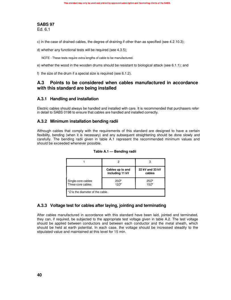
A.3.2 Minimum installation bending radii Although cables that comply with the requirements of this standard are designed to have a certain flexibility, bending (when it is necessary) and any subsequent straightening should be done slowly and carefully. The bending radii given in table A.1 represent the recommended minimum values and should be exceeded whenever possible.
Table A.1 — Bending radii
1 2 3
Cables up to and 22 kV and 33 kV including 11 kV cables
Single-core cables 20D* 25D* Three-core cables 12D* 15D*
*D is the diameter of the cable.
A.3.3 Voltage test for cables after laying, jointing and terminating After cables manufactured in accordance with this standard have been laid, jointed and terminated, they can, if required, be subjected to the appropriate test voltage given in table A.2. The test voltage should be applied between conductors and between each conductor and the metal sheath, which should be held at earth potential. In each case, the voltage should be increased steadily to the stipulated value and maintained at this level for 15 min.
40

This standard may only be used and printed by approved subscription and freemailing clients of the SABS.
SABS 97 Ed. 6.1
Table A.2 — In-situ test voltages
Values in kilovolts
1 2 3 4 5
Test voltage
Voltage Belted cables rating of
6 7
Single-core and screened cables
cable
3,3/3,3 3,8/6,6 6,6/6,6 6,35/11 11/11 12,7/22 19/33
Between conductors
a.c. d.c.
7 9 13 19 13 19 22 31 22 31 - - - -
From conductor Between conductor and to sheath sheath or screen
a.c. d.c. a.c. d.c.
7 9 - - 8 11 8 11
13 19 - - 13 19 13 19 22 31 - -
- - 25 36 - - 38 54
Annex B (informative)
Bibliography SABS 0198-1:1988, The selection, handling and installation of electric power cables of rating not
exceeding 33 kV - Part 1: Definitions and statutory requirements.
SABS 0198-2:1988, The selection, handling and installation of electric power cables of rating not
exceeding 33 kV - Part 2: Choice of cable type and methods of installation.
SABS 0198-3:1988, The selection, handling and installation of electric power cables of rating not
exceeding 33 kV - Part 3: Earthing systems - General provisions.
SABS 0198-4:1988, The selection, handling and installation of electric power cables of rating not
exceeding 33 kV - Part 4: Current ratings.
SABS 0198-8:1988, The selection, handling and installation of electric power cables of rating not
exceeding 33 kV - Part 8: Cable laying and installation.
SABS 0198-10:1988, The selection, handling and installation of electric power cables of rating not
exceeding 33 kV - Part 10: Jointing and termination of paper-insulated cables. SABS SM 1281-4:1999, Test methods for impregnated paper-insulated electric cables - Part 4: Tests after installation.
SABS SM 1282-1:1999, Test methods for conductors of insulated electric cables - Part 1: Conductor resistance.
sabs pta (pdf)
41