use of multiple extractions to thermodynamically balance the humidification dehumidification...
TRANSCRIPT

International Journal of Heat and Mass Transfer 68 (2014) 422–434
Contents lists available at ScienceDirect
International Journal of Heat and Mass Transfer
journal homepage: www.elsevier .com/locate / i jhmt
Use of multiple extractions and injections to thermodynamically balancethe humidification dehumidification desalination system
0017-9310/$ - see front matter � 2013 Elsevier Ltd. All rights reserved.http://dx.doi.org/10.1016/j.ijheatmasstransfer.2013.09.025
⇑ Corresponding author.E-mail address: [email protected] (J.H. Lienhard V).
1 Joint first authors.
Karim M. Chehayeb a,1, G. Prakash Narayan b,1, Syed M. Zubair c, John H. Lienhard V a,⇑a Department of Mechanical Engineering, Massachusetts Institute of Technology, Cambridge, MA 02139, USAb Gradiant Corporation, Woburn, MA 01801, USAc Department of Mechanical Engineering, King Fahd University of Petroleum and Minerals, Dhahran, Saudi Arabia
a r t i c l e i n f o a b s t r a c t
Article history:Received 11 June 2013Received in revised form 9 September 2013Accepted 13 September 2013Available online 15 October 2013
Keywords:DesalinationHumidificationDehumidificationThermodynamic balancingEnthalpy pinchEntropy generation minimizationMass extractionHeat and mass exchangers
Humidification dehumidification (HDH) desalination systems are well suited for small scale, off-griddesalination. These systems are very robust and can tolerate a wide range of feed salinities, making thema good candidate for treating produced water from hydraulically fractured natural gas wells. A primaryengineering challenge for these systems is their high thermal energy consumption. In this study, weexamine the use of multiple air extractions and injections to thermodynamically balance the HDH sys-tem, so as to make it more energy efficient. The effect of the number of extractions on several perfor-mance parameters is studied. In addition, we study the effect of the enthalpy pinch, which is ameasure of performance for a heat and mass exchanger, on these performance parameters. Finally, wepresent results that can be used as guidelines in designing HDH systems. These results include the iden-tification of appropriate temperatures for the extracted/injected air streams, the division of the heat dutybetween stages, and the value of the mass flow rate ratio in each stage at various values of enthalpypinch.
� 2013 Elsevier Ltd. All rights reserved.
1. Introduction
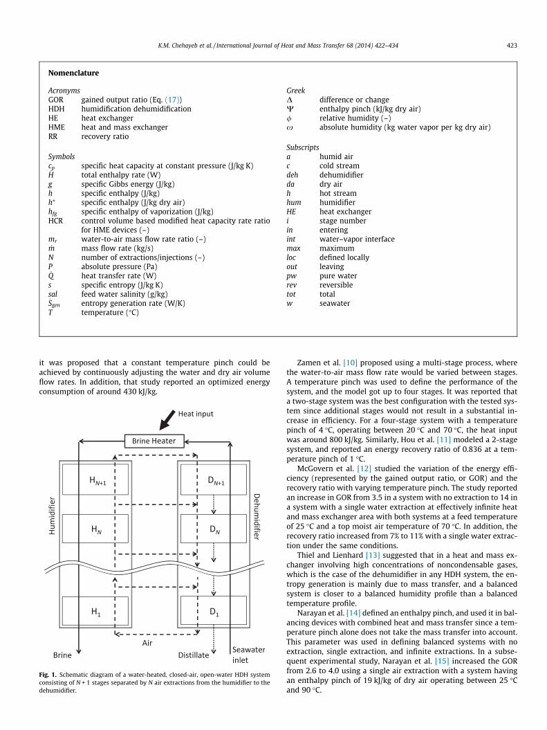
Humidification dehumidification (HDH) is a distillation technol-ogy which imitates the rain cycle in a controlled fashion by using acarrier gas, such as air [1–3], to transport water vapor between dif-ferent compartments. The most basic system consists of a humid-ifier, a dehumidifier, and a heater. As shown in Fig. 1, cold airenters the humidifier where it is directly exposed to a hot streamof saline water, so its temperature increases, thus increasing itscapacity to hold water vapor. Water from the saline water streamthus evaporates, making the air stream more humid. The humid airis then taken to the dehumidifier, where it is put in indirect contactwith the cold incoming saline water stream. The temperature ofthe air decreases, causing some of the water vapor to condense,thus supplying a stream of pure water.
HDH is a promising technology for small scale desalination andis appropriate for water production in remote, off-grid locationswhere the water demand is not large enough to justify installinglarge scale plants. In addition, HDH systems do not require verysophisticated components and maintenance. Furthermore, HDH isa very robust technology, which, unlike membrane based technol-
ogies, can treat very saline water (many times saltier than seawa-ter), which makes it a strong candidate for addressing the problemof produced water from natural gas wells. The major limitation ofthis technology is its high energy consumption. However, the en-ergy requirements can be reduced through a careful understandingof the thermodynamics underpinning this technology so as to re-duce the entropy generation within the operating cycle [4–6]. Ithas been shown previously that the entropy production rate is ata minimum when the heat capacity rates of the interacting streamsin a heat and mass exchanger are equal [7]. This thermodynami-cally balanced system can be achieved through the variation ofthe mass flow rate ratio of the interacting streams (namely waterand air) in each of the humidifier and dehumidifier which maybe attained by mass extraction and injection between the twocomponents at one or more internal locations [2]. In this study,we consider air extractions from the humidifier to the dehumidi-fier as shown in Fig. 1.
1.1. Literature review
Previous attempts to increase the energy efficiency of HDHdesalination systems using mass extraction/injection have been re-ported in the literature. Müller-Holst [8,9] suggested that entropygeneration is minimized when the stream-to-stream temperaturedifference is kept constant throughout the system. In that study,
Nomenclature
AcronymsGOR gained output ratio (Eq. (17))HDH humidification dehumidificationHE heat exchangerHME heat and mass exchangerRR recovery ratio
Symbolscp specific heat capacity at constant pressure (J/kg K)_H total enthalpy rate (W)g specific Gibbs energy (J/kg)h specific enthalpy (J/kg)h⁄ specific enthalpy (J/kg dry air)hfg specific enthalpy of vaporization (J/kg)HCR control volume based modified heat capacity rate ratio
for HME devices (–)mr water-to-air mass flow rate ratio (–)_m mass flow rate (kg/s)
N number of extractions/injections (–)P absolute pressure (Pa)_Q heat transfer rate (W)
s specific entropy (J/kg K)sal feed water salinity (g/kg)_Sgen entropy generation rate (W/K)T temperature (�C)
GreekD difference or changeW enthalpy pinch (kJ/kg dry air)/ relative humidity (–)x absolute humidity (kg water vapor per kg dry air)
Subscriptsa humid airc cold streamdeh dehumidifierda dry airh hot streamhum humidifierHE heat exchangeri stage numberin enteringint water–vapor interfacemax maximumloc defined locallyout leavingpw pure waterrev reversibletot totalw seawater
K.M. Chehayeb et al. / International Journal of Heat and Mass Transfer 68 (2014) 422–434 423
it was proposed that a constant temperature pinch could beachieved by continuously adjusting the water and dry air volumeflow rates. In addition, that study reported an optimized energyconsumption of around 430 kJ/kg.
Fig. 1. Schematic diagram of a water-heated, closed-air, open-water HDH systemconsisting of N + 1 stages separated by N air extractions from the humidifier to thedehumidifier.
Zamen et al. [10] proposed using a multi-stage process, wherethe water-to-air mass flow rate would be varied between stages.A temperature pinch was used to define the performance of thesystem, and the model got up to four stages. It was reported thata two-stage system was the best configuration with the tested sys-tem since additional stages would not result in a substantial in-crease in efficiency. For a four-stage system with a temperaturepinch of 4 �C, operating between 20 �C and 70 �C, the heat inputwas around 800 kJ/kg. Similarly, Hou et al. [11] modeled a 2-stagesystem, and reported an energy recovery ratio of 0.836 at a tem-perature pinch of 1 �C.
McGovern et al. [12] studied the variation of the energy effi-ciency (represented by the gained output ratio, or GOR) and therecovery ratio with varying temperature pinch. The study reportedan increase in GOR from 3.5 in a system with no extraction to 14 ina system with a single water extraction at effectively infinite heatand mass exchanger area with both systems at a feed temperatureof 25 �C and a top moist air temperature of 70 �C. In addition, therecovery ratio increased from 7% to 11% with a single water extrac-tion under the same conditions.
Thiel and Lienhard [13] suggested that in a heat and mass ex-changer involving high concentrations of noncondensable gases,which is the case of the dehumidifier in any HDH system, the en-tropy generation is mainly due to mass transfer, and a balancedsystem is closer to a balanced humidity profile than a balancedtemperature profile.
Narayan et al. [14] defined an enthalpy pinch, and used it in bal-ancing devices with combined heat and mass transfer since a tem-perature pinch alone does not take the mass transfer into account.This parameter was used in defining balanced systems with noextraction, single extraction, and infinite extractions. In a subse-quent experimental study, Narayan et al. [15] increased the GORfrom 2.6 to 4.0 using a single air extraction with a system havingan enthalpy pinch of 19 kJ/kg of dry air operating between 25 �Cand 90 �C.

424 K.M. Chehayeb et al. / International Journal of Heat and Mass Transfer 68 (2014) 422–434
1.2. Goals of the current study
This study complements the previous paper by Narayan et al.[14]. We examine the effect of a finite number of extractions on en-ergy efficiency, water recovery, and total heat duty. We also aim tounderstand when it is useful to use extractions and injections, andhow many should be used for systems of different size. Addition-ally, we present results that can be used in designing HDH systems,including the division of the heat duty between stages, the massflow rate ratio in each stage, and the temperatures of the ex-tracted/injected air streams.
2. Modeling
2.1. Definition of a balanced system
Previous studies by Narayan et al. [7,16] concluded that entropygeneration is minimized at a fixed energy effectiveness when themodified heat capacity rate ratio (HCR) in the dehumidifier is equalto unity, where:
HCR ¼ DH_
max;cold
DH_
max;hot
ð1Þ
In Eq. (1), the numerator and denominator can both be divided bythe mass flow rate of dry air, and, as shown in Fig. 2, the resultingequation can be written as follows:
HCR ¼Dh�max;cold
Dh�max;hot
¼ Dh� þWdeh;cold
Dh� þWdeh;hotð2Þ
where W is the enthalpy pinch [14], which may be thought of as theminimum loss of enthalpy rate due to a finite device size. For HCR tobe equal to unity in the dehumidifier, we need Wdeh,cold = Wdeh,hot.This means that in a balanced HDH system the enthalpy pinch pointwill be located at the inlet and outlet of the dehumidifier, and at asingle intermediate location in the humidifier. The same definitionis used for a system with multiple extractions and injections, where
Fig. 2. Temperature-enthalpy profile of a balanced system without extractions/in
each stage (between two consecutive extraction or injection points)satisfies these conditions.
2.2. Conservation equations and solution method
As explained in previous publications [12,14], the HDH systemcan be modeled using temperature-enthalpy diagrams. These dia-grams allow the representation of the process paths followed byeach of the interacting streams, namely, moist air and seawaterin the humidifier, and moist air, seawater, and distillate in thedehumidifier. Having the process paths defined allows the calcula-tion of the enthalpy pinch at any location in the heat and massexchangers. The enthalpy in these diagrams is expressed in kJ perkg of dry air since normalizing it in this fashion, as suggested byMcGovern et al. [12], allows the representation of the processpaths of air and water on the same diagram, and inherently satis-fies the energy balance as will be shown in this section. The air, as-sumed to be saturated at all times, follows the air saturation curve,where the enthalpy is only a function of temperature.
Fig. 3 shows a control volume containing the heater and por-tions of the humidifier and the dehumidifier. The control volumeis chosen such that it intersects the humidifier and the dehumidi-fier in a location where the air is at the same temperature and massflow rate in both components. The intersection of the control vol-ume with both components corresponds to a vertical line (constantspecific enthalpy of dry air) on the temperature-enthalpy profile.The water content in the air entering the control volume in thehumidifier is the same as that in the air exiting the control volumein the dehumidifier since the air is saturated and at the same tem-perature. A water mass balance on this control volume results in
_mw;hum ¼ _mw;deh � _mpw;loc ð3Þ
where the ‘‘loc’’ subscript denotes that the mass flow rate indicatedis that of pure water condensed starting from the hot end of thedehumidifier up to the location in question. Note that, in the dehu-midifier, the saline water is not in contact with the air so its massflow rate is constant throughout the dehumidifier, and the salinewater that enters the heater and the humidifier has the same mass
jections with Tfeed = 20 �C, Ttop brine = 80 �C, and Whum = Wdeh = 20 kJ/kg dry air.

Fig. 3. A control volume containing the heater, a section of the dehumidifier andthe corresponding section of the humidifier.
K.M. Chehayeb et al. / International Journal of Heat and Mass Transfer 68 (2014) 422–434 425
flow rate as the feed saline water, _mw. So at any location in thehumidifier,
_mw;hum ¼ _mw � _mpw;loc ð4Þ
A more intuitive way to look at this result is that, at any location inthe humidifier, the mass flow rate of saline water is the mass flowrate of water at the inlet of the humidifier minus the amount ofwater that has evaporated up to this location.
Fig. 4(a) represents a control volume containing a small sectionof the dehumidifier. A water mass balance on this control volumeresults in
_mpw;1 � _mpw;2 ¼ _mdaðx2 �x1Þ ð5Þ
In addition, an energy balance on the same control volume can beexpressed as
ð _H2 � _H1Þw � ð _H2 � _H1Þpw ¼ ð _H2 � _H1Þa ð6Þ
or
_mwcp;w T2 � T1ð Þw � _mcpT� �
pw;2 � _mcpT� �
pw;1
h i¼ _mda h�2 � h�1
� �ð7Þ
For an infinitesimally small control volume, the change in the en-thalpy rate of pure water is mainly due to temperature change, so
(a) Control volume
(b) Control volume
Fig. 4. Diagrams showing the control volumes used in the conservation of m
the change in mass flow rate of pure water inside the control vol-ume can be neglected, such that _mpw;2 ¼ _mpw;1 ¼ _mpw;loc . Assumingthat, at any location in the dehumidifier, the condensed water isat the same temperature as the saline water, and that the specificheat capacity of water is constant and the same for pure waterand saline water, the energy balance simplifies to
_mw � _mpw;loc
� �cp;w T2 � T1ð Þw ¼ _mda h�2 � h�1
� �ð8Þ
Dividing Eq. (8) by the product ð _mw � _mpw;locÞcp;wðh�2 � h�1Þ, and tak-ing the limit as ðh�2 � h�1Þ goes to zero, we obtain the followingexpression for the slope of the process path followed by the waterstream in the dehumidifier on the temperature-enthalpy diagram:
dTw
dh�¼ 1
mrcp;wð9Þ
where the mass flow rate ratio, mr, is the ratio of the net mass flowrate of water to that of dry air:
mr ¼_mw � _mpw;loc
_mdað10Þ
Similarly, an energy balance can be applied on the humidifier controlvolume shown in Fig. 4(b) and can be combined with Eq. (4) to give
ð _H2 � _H1Þw ¼ ð _H2 � _H1Þa ð11Þ
and
_mw � _mpw;loc
� �cp;w T2 � T1ð Þw ¼ _mdaðh�2 � h�1Þ ð12Þ
The resulting equation is the same as Eq. (8), which indicates that theslope of the process path of water in the humidifier is also given by Eq.(9), and, on the temperature-enthalpy diagrams, the humidifier anddehumidifier lines should always be parallel. As a result of Eq. (9),varying the mass flow rate ratio through extractions of air from thehumidifier to the dehumidifier allows the modification of the slopeof the water process paths on the temperature-enthalpy diagram,and hence allows the balancing of the heat and mass exchangers.
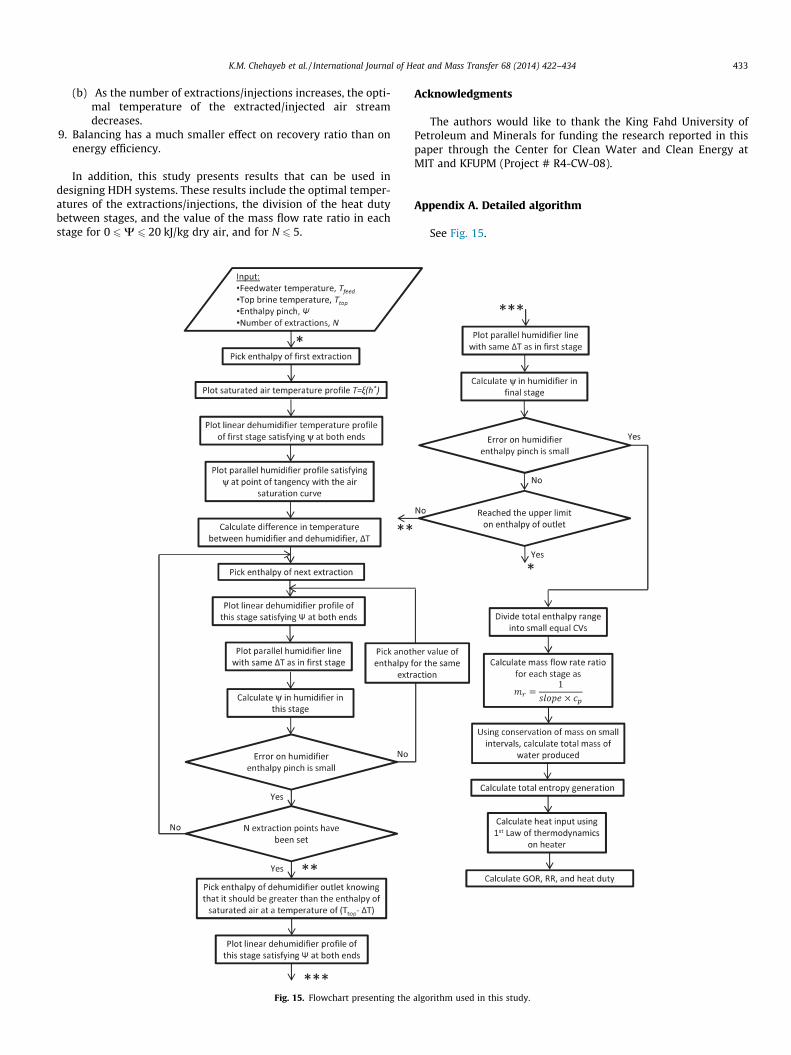
In the present paper, the boundary conditions used in all simu-lations are a feed water temperature of 20 �C and a top brine tem-perature of 80 �C. The primary independent variables are thenumber of extractions, N, and the enthalpy pinch, W. The algorithmused in this study is presented in the form of a flowchart in Fig. 15in the Appendix. The first part of the calculations is purely
in the dehumidifier
in the humidifier
ass and energy equations in (a) the dehumidifier and (b) the humidifier.

426 K.M. Chehayeb et al. / International Journal of Heat and Mass Transfer 68 (2014) 422–434
numerical and consists of finding the correct temperatures of theextracted/injected air streams that yield a balanced system, asdefined in Section 2.1. After finding the appropriate temperature-enthalpy profile for a given N and W, we can calculate all theparameters needed to evaluate the performance of the system. Atypical balanced temperature-enthalpy profile is shown in Fig. 5,where N = 3 and W = 3 kJ/kg dry air.
Eq. (9) can be rearranged to calculate the mass flow rate ratio inthe final stage of the system:
mr ¼1
dTwdh� � cp;w
ð13Þ
As explained in Sections 2.3 and 3.2, the mass flow rate ratio is as-sumed constant in each stage. In addition, at the hot end of thedehumidifier, _mpw;loc ¼ 0 kg/s so the mass flow rate of dry air inthe final stage can be calculated using Eq. (10). Given _mda;Nþ1, theamount of pure water produced in the final stage can be calculated:
_mpw;Nþ1 ¼ _mda;Nþ1DxNþ1 ð14Þ
Eq. (13) can then be used to calculate the mass flow rate ratio in theNth stage, and, having calculated _mpw;Nþ1, which is the local massflow rate of pure water at the inlet of the Nth stage, _mda;N can be cal-culated using Eq. (10). The same procedure can be repeated to findthe mass flow rate of dry air in each stage.
Additionally, the total mass flow rate of product water can becalculated:
_mpw;tot ¼XNþ1
stage;i¼1
_mda;iDxi ð15Þ
Finally, the total heat input into the system is calculated byapplying the First Law of Thermodynamics on the heater:_Q in ¼ _mwDhw ð16Þ
2.3. Assumptions and approximations
� Specific heat capacity of water is assumed constant, evaluated at50 �C, and a salinity of 35 ppt (maximum actual variation <5%).
Fig. 5. Temperature-enthalpy profile of a balanced system with 3 extract
� Temperature-enthalpy data for saturated air is input into theMATLAB code in the form of an array with a finite differencebetween consecutive data points. The discretization of the data-base is small enough such that the resulting uncertainty is rea-sonably small (�1%).� In the dehumidifier, pure water is produced at the tempera-
ture of seawater at the corresponding location. This meansthat pure water and seawater follow the same process pathin the dehumidifier. The maximum error resulting from thisassumption is small (<2%) and is discussed in an earlier pub-lication [14].� Air is assumed to be always saturated, which means the process
path of air on the temperature-enthalpy diagrams is the same asthe air saturation curve (discussed in previous publications, andshown to have an uncertainty <10% [12,14]).� An additional assumption to further simplify the modeling pro-
cedure of multiple extractions/injections is that of a constantmass flow rate ratio in each stage. This is discussed in detailin Section 3.2 of the present study.
2.4. Performance parameters
In order to assess the performance of an HDH system, we needto first evaluate its energy efficiency. A common parameter used inthermal desalination systems is the gained output ratio, or GOR,which is the ratio of the latent heat of vaporization of the productwater to the net heat input to the system:
GOR ¼_mpwhfg
_Q in
ð17Þ
GOR is a dimensionless quantity which measures the extent of re-use of the heat input. The most basic distillation system that usesheat to directly boil water without recovery of the heat of conden-sation would have at most a GOR of 1. In the present study, hfg istaken constant and equal to 2400 kJ/kg.
Another parameter of interest is the recovery ratio, RR. It is de-fined as the amount of pure water produced per unit amount offeed entering the system.
ions/injections, Tfeed = 20 �C, Ttop brine = 80 �C, and W = 3 kJ/kg dry air.

K.M. Chehayeb et al. / International Journal of Heat and Mass Transfer 68 (2014) 422–434 427
RR ¼_mpw
_mwð18Þ
A third parameter used in this study is the heat duty, which isthe total energy transfer between the interacting streams summedover all stages of a single component type (humidifiers or dehu-midifiers) per unit amount of water produced.
_Q duty ¼PNþ1
stage;i¼1 _mda;iDh�i_mpw
ð19Þ
In a closed-air system, such as the one studied here, the heat duty isthe same in both the humidifier and the dehumidifier. The heatduty, along with the driving force (e.g. temperature difference fora heat exchanger), determines the size of the heat and massexchangers [17]. Therefore, at a constant enthalpy pinch, the heatduty can be used as a rough indicator of the initial cost of the sys-tem. It should be noted that the heat duty is different from (and lar-ger than) the heat input, _Qin.
2.5. Property packages
� The thermophysical properties of seawater were evaluatedusing the correlations developed by Sharqawy et al. [18].� Thermophysical properties of pure water are evaluated using
the IAPWS (International Association for Properties of Waterand Steam) 1995 Formulation [19].� Moist air properties are evaluated assuming an ideal mixture of
air and steam using the formulations of Hyland and Wexler [20].
Moist air properties thus calculated are in close agreement withthe data presented in ASHRAE Fundamentals [21] and pure waterproperties are equivalent to those found in NIST’s property pack-age, REFPROP [22].
3. Results and discussion
3.1. Experimental validation
In a recent study, Narayan et al. [15] built an HDH system hav-ing an enthalpy pinch of 19 kJ/kg dry air at optimal operation. TheGOR of the system without any extractions was 2.6, and that of asystem with a single extraction/injection was 4.0. The systemdescribed in that study operated between 25 �C and 90 �C andhad an uncertainty of ±5% on GOR. Performing the numerical
(a) Comparison of models with fixed and modified mass flow rate ratios f or N = 0 (
Fig. 6. Effect of assuming fixed mass flow r
calculations at these boundary conditions and at W = 19 kJ/kg dryair, the calculated GOR was 2.3 for the case of no extraction (11%difference) and 4.7 for that of a single extraction (17% difference).The deviation of the experimental results from the numericalresults presented in this paper is expected since the experimentalsetup had some heat losses to the environment. The experimentalsystem also had additional entropy generation due to mixing wheninjecting the air stream into the dehumidifier, and the ambientconditions could have varied slightly. In addition, the numericalstudy uses some simplifying assumptions, as explained in Section2.3, which leads to a small error in the values of GOR. Nonetheless,the reported results are reasonably close to the experimentalresults, and serve the main purpose of showing trends in thevariation of the different performance parameters with varyingenthalpy pinch and number of extractions/injections.
3.2. Effect of assuming fixed mass flow rate ratio
In the results reported in the following sections, the mass flowrate ratio, defined in Eq. (10), is kept constant in each stage of boththe humidifier and the dehumidifier. This results from the assump-tion that the water flow rate is kept constant in each of these com-ponents. In other words, the effect of condensation on the flow rateof water in a dehumidifier stage and evaporation in the corre-sponding humidifier stage can be neglected since the mass flowrate of the condensed or evaporated water is very small comparedto that of the mass flow rate of saline water. This approximation,along with that of a constant specific heat capacity of water, trans-lates into a constant slope (Eq. (9)), so the process path of water ineach stage will be a straight line, making the numerical computa-tion much simpler and faster.
In order to estimate the error caused by this approximation,additional calculations were done in which the mass flow rate ratiowas actually varied to account for condensation and evaporationfor the cases of no extraction and single extraction. The maximumerror on the gained output ratio, GOR, was found to be around 1%for the case of no extraction (Fig. 6), and 2.5% for that of singleextraction (Fig. 6). As will be shown in Section 3.5, the recoveryratio converges to a maximum, and, after the first extraction, theincrease in recovery ratio is limited. This, in turn, means that theerror due to the assumption of constant mass flow rate ratio withineach stage will not increase significantly for a higher number ofextractions since condensation and evaporation are bounded bythe total recovery.
b) Comparison of models with fixed and modified mass flow rate ratios f or N = 1
ate ratio on GOR for (a) N = 0 (b) N = 1.
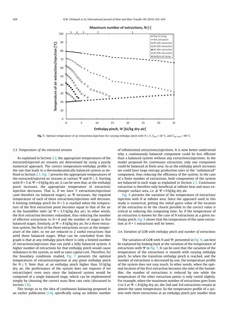
Fig. 7. Optimal temperature of air extractions/injections for varying enthalpy pinch with N 6 5, Tfeed = 20 �C, and Ttop brine = 80 �C.
428 K.M. Chehayeb et al. / International Journal of Heat and Mass Transfer 68 (2014) 422–434
3.3. Temperature of the extracted streams
As explained in Section 2.2, the appropriate temperatures of theextracted/injected air streams are determined by using a purelynumerical approach. The correct temperature-enthalpy profile isthe one that leads to a thermodynamically balanced system as de-fined in Section 2.1. Fig. 7 presents the appropriate temperatures ofthe extracted/injected air streams at various W and N 6 5. Startingwith N = 5 at W = 0 kJ/kg dry air, it can be seen that, as the enthalpypinch increases, the appropriate temperature of extraction/injection decreases. That is, if we have 5 extractions/injections(and therefore six balanced stages), as W increases, the requiredtemperature of each of these extractions/injections will decrease.A limiting enthalpy pinch for N = 5 is reached when the tempera-ture of the first extraction point becomes equal to that of the airat the humidifier inlet (at W � 3.5 kJ/kg dry air). In other words,the first extraction becomes redundant, thus reducing the numberof effective extractions to N = 4 and the number of stages to fivebalanced stages. Similarly, at W � 8 kJ/kg dry air, for a three extrac-tion system, the first of the three extractions occurs at the temper-ature of the inlet, so we are reduced to 2 useful extractions thatyield three balanced stages. What can be concluded from thisgraph is that at any enthalpy pinch there is only a limited numberof extractions/injections that can yield a fully balanced system. Ahigher number of extractions for that enthalpy pinch would causeimbalance in the system, as well as raise capital cost. Therefore, forthe boundary conditions studied, Fig. 7 presents the optimaltemperatures of extraction/injection at any given enthalpy pinchfor N 6 5. Note that, at an enthalpy pinch higher than 35 kJ/kgdry air, the performance of the system does not improve if weextract/inject even once since the balanced system would becomposed of a single balanced stage, which can be implementedsimply by choosing the correct mass flow rate ratio (discussed inSection 3.8).
This brings us to the idea of continuous balancing proposed inan earlier publication [14], specifically using an infinite number
of infinitesimal extractions/injections. It is now better understoodwhy a continuously balanced component could be less efficientthan a balanced system without any extractions/injections. In themodel proposed for continuous extraction, only one componentcould be balanced at finite area. So as the enthalpy pinch increaseswe could have large entropy production rates in the ‘‘unbalanced’’component, thus reducing the efficiency of the system. In the caseof a finite number of extractions, both components of the systemare balanced in each stage as explained in Section 2.1. Continuousextraction is therefore only beneficial at infinite heat and mass ex-changer surface area, i.e. at W = 0 kJ/kg dry air.
Fig. 8 presents the variation of the temperature of extraction/injection with N at infinite area. Since the approach used in thisstudy is numerical, getting the initial guess value of the locationof the extraction to be the closest possible to the correct value iscritical in reducing the computing time. So, if the temperature ofan extraction is known for the case of N extractions at a given en-thalpy pinch, Fig. 8 shows that the temperature of the same extrac-tion at N + 1 extractions will be lower.
3.4. Variation of GOR with enthalpy pinch and number of extractions
The variation of GOR with N and W, presented in Fig. 9, can bestbe explained by looking back at the variation of the temperature ofextractions with W in Fig. 7. It can be seen that the variation of thetemperature of the extractions is smooth with varying enthalpypinch. So when the transition enthalpy pinch is reached, and thenumber of extractions is decreased by one, the temperature profileof the system does not vary much. In other words, when the opti-mal location of the first extraction becomes the inlet of the humid-ifier, the number of extractions is reduced by one while thetemperature of the other extraction points is only varied slightly.For example, when the maximum number of extractions goes from3 to 2 at W � 8 kJ/kg dry air, the 2nd and 3rd extractions remain atalmost the same temperature. So the temperature profile of a sys-tem with three extractions at an enthalpy pinch just smaller than

Fig. 9. Variation of GOR with enthalpy pinch, W, and number of extractions/injections, N. Boundary conditions: Tfeed = 20 �C, Ttop brine = 80 �C.
Fig. 8. Temperature of air extractions/injections at infinite area (W = 0 kJ/kg dry air) for varying number of extractions/injections, N.
K.M. Chehayeb et al. / International Journal of Heat and Mass Transfer 68 (2014) 422–434 429
the transition enthalpy pinch will be the same as that of a systemwith two extractions at an enthalpy pinch just larger than the tran-sition pinch. This means that the characteristics of these systemswill be very close, which explains why the curves of GOR at variousN intersect. Thus, at the transition enthalpy pinch between N andN + 1 extractions, the system with N extractions and that withN + 1 extractions have the same GOR, among other parameters,namely RR, heat duty, and mass flow rate ratio in each stage.
As expected, at a constant N, GOR decreases with increasing W.This is true since the difference in both, temperature and humidity,
is larger at larger W, which means that the entropy generation isgreater, and the energy efficiency is smaller. In addition, at a con-stant W, the GOR is greater at a larger number of extractions sincethe process paths of the interacting streams become closer, and thedriving forces for the heat and mass transfer become smaller,reducing the entropy generation and increasing the energyefficiency.
Another observation from Fig. 9 is that the effect of extracting islargest at infinite area where each additional extraction increasesthe efficiency by a significant amount. The larger the enthalpy

430 K.M. Chehayeb et al. / International Journal of Heat and Mass Transfer 68 (2014) 422–434
pinch, the smaller the effect of additional extractions/injections.Also, when the enthalpy pinch is greater than 6 kJ/kg dry air, wenotice that extractions/injections have diminishing returns assuggested by Zamen et al. [10]. That is, the increase in efficiencydue to an additional extraction is smaller than the increase dueto the previous extraction. For example, at W = 7 kJ/kg dry air,the first extraction improves GOR by 3.9, the second by 3.6, andthe third by 1.2. This observation is not true for W 6 6 kJ/kg dryair where each additional extraction brings a significant increase
Fig. 11. Variation of Heat Duty with enthalpy pinch, W, and number of extr
Fig. 10. Variation of RR with enthalpy pinch, W, and number of extracti
in efficiency, in some cases even greater than that due to the pre-vious extraction.
3.5. Variation of recovery ratio with enthalpy pinch and number ofextractions
As can be seen in Fig. 10, for the same number of extractions/injections, the recovery ratio decreases with increasing enthalpypinch, and, as was explained in Section 3.4, the recovery ratio of
actions/injections, N. Boundary conditions: Tfeed = 20 �C, Ttop brine = 80 �C.
ons/injections, N. Boundary conditions: Tfeed = 20 �C, Ttop brine = 80 �C.

K.M. Chehayeb et al. / International Journal of Heat and Mass Transfer 68 (2014) 422–434 431
N + 1 extractions intersects that of N extractions at the transition en-thalpy pinch. The recovery ratio increases with the number ofextractions/injections; however, this increase becomes smaller witheach additional extraction/injection. For a closed-air, open-water(CAOW) system operating between 20 �C and 80 �C, and balancedusing air extractions/injections, the recovery ratio converges to alimit close to 7.6% at infinite area as N goes to infinity.
When comparing Fig. 10 to Fig. 9, we notice that balancingthrough air extractions and injections has a much larger effect onenergy efficiency than on recovery ratio.
3.6. Variation of heat duty with enthalpy pinch and number ofextractions
The variation of heat duty with N and W, shown in Fig. 11,is similar to that of recovery ratio. The total heat duty
(a) Ψ = 0 kJ/kg dry air
Fig. 12. Distribution of heat duty between the stages of the system at various numbers opercentage of the total heat duty in each stage is displayed in the corresponding colum
Fig. 13. Optimal distribution of heat duty between the stage
decreases with increasing enthalpy pinch. Also, the heat dutyincreases with the number of extractions/injections until itreaches a limit of about 3050 kJ/kg of distillate for our bound-ary conditions at infinite area. It can be seen that the variationof the heat duty at N P 3 at W close to 0 is not very smooth,but we should note that the variation is between 3020 and3050 kJ/kg of distillate, which is less than 1%, and falls withinthe numerical error range.
An important observation to be made is that a small increase inheat duty can lead to a large increase in GOR. For example, atW = 15 kJ/kg dry air, the first extraction will double the GOR whileonly needing a 4% increase in heat duty, which suggests a signifi-cant increase in performance at only a modest increase in systemcost. As noted in Section 3.4, GOR increases faster with N at W closeto 0, whereas the variation of heat duty with N becomes very smallin that region. This means that the additional efficiency comes at a
(b) Ψ = 2 kJ/kg dry air
f extractions/injections, N, at (a) W = 0 kJ/kg dry air and (b) W = 2 kJ/kg dry air. Then.
s of the system at varying enthalpy pinch, W, and N 6 5.

Fig. 14. Optimal mass flow rate ratio at each stage in the system for varying enthalpy pinch, W, and N 6 5.
432 K.M. Chehayeb et al. / International Journal of Heat and Mass Transfer 68 (2014) 422–434
cheap price if we can achieve a low enthalpy pinch at an acceptablecost.
3.7. Division of heat duty between stages
The data presented in this section could be considered as aguideline in designing an HDH system. Fig. 12(a) presents thedivision of the total heat duty between the different stages of thesystem at infinite area (which corresponds to W = 0 kJ/kg dry air).As a rough estimate, the heat duty is almost divided equally be-tween the different stages. The farther the system is from infinitearea, the less uniform the division of the heat duty at high N, asshown in Fig. 12(b).
The same results can be seen in Fig. 13, which presents the opti-mal division of heat duty between stages for various values of en-thalpy pinch. This means that the cases presented show themaximum number of extractions possible at any given W (whereN 6 5). Starting with six stages at W = 0 kJ/kg dry air, the heat dutyis almost divided equally between stages. As W increases, the frac-tion of the heat duty in the first stage decreases before reaching 0at the transition enthalpy pinch, and thus the number of extrac-tions/injections is reduced by 1.
3.8. Optimal values for mass flow rate ratio for varying enthalpy pinch
Fig. 14 shows the optimal value of the mass flow rate ratio ineach stage at various values of enthalpy pinch. As expected, themass flow rate ratio is always higher in the hotter stages sincewe are extracting air from the humidifier and injecting it in thedehumidifier. So there is more air at the lower stages, and hencea lower mass flow rate ratio. In addition, the mass flow rate ratiodecreases in each stage with increasing enthalpy pinch until a min-imum mr of around 1 is reached in the first stage at the transitionenthalpy pinch. After some investigation, it was found that the
mass flow rate ratio is close to 1 due the boundary conditionTfeed = 20 �C since in that region dTa
dh� � cp;w.
4. Conclusions
The effect of the number of extractions and the enthalpy pinchon various performance parameters of a closed-air, open-waterhumidification dehumidification system has been studied. Themain conclusions of this work are the following:
1. At a given enthalpy pinch, we can only extract/inject benefi-cially a limited number of times.
2. Continuous extraction, as proposed in an earlier publication[14], can only fully balance one component. Therefore, at agiven enthalpy pinch, continuous extraction can be less benefi-cial than a finite number of extractions, which is able to balanceboth components.
3. Recovery ratio converges to a maximum as the number ofextractions/injections increases.
4. Total heat duty converges to a maximum as the number ofextractions/injections increases.
5. When modeling closed-air, open-water HDH systems withair extractions/injections, the change in mass flow rate ratio dueto evaporation/condensation within a stage can be neglected.
6. A small increase in heat duty can lead to a large increase inenergy efficiency, especially at a small enthalpy pinch.
7. The effect of balancing through extraction/injection is greater atsmaller enthalpy pinch, where GOR increases faster with N andheat duty remains approximately constant. At larger enthalpypinch (smaller heat and mass transfer surface area), balancinghas diminishing returns.
8. Location of the injection points:(a) As the enthalpy pinch increases, the optimal temperature
of the extracted/injected air stream decreases.
K.M. Chehayeb et al. / International Journal of Heat and Mass Transfer 68 (2014) 422–434 433
(b) As the number of extractions/injections increases, the opti-mal temperature of the extracted/injected air streamdecreases.
9. Balancing has a much smaller effect on recovery ratio than onenergy efficiency.
In addition, this study presents results that can be used indesigning HDH systems. These results include the optimal temper-atures of the extractions/injections, the division of the heat dutybetween stages, and the value of the mass flow rate ratio in eachstage for 0 6W 6 20 kJ/kg dry air, and for N 6 5.
Fig. 15. Flowchart presenting the
Acknowledgments
The authors would like to thank the King Fahd University ofPetroleum and Minerals for funding the research reported in thispaper through the Center for Clean Water and Clean Energy atMIT and KFUPM (Project # R4-CW-08).
Appendix A. Detailed algorithm
See Fig. 15.
algorithm used in this study.
434 K.M. Chehayeb et al. / International Journal of Heat and Mass Transfer 68 (2014) 422–434
References
[1] G.P. Narayan, M.H. Sharqawy, E.K. Summers, J.H. Lienhard V, S.M. Zubair, M.A.Antar, The potential of solar-driven humidification–dehumidificationdesalination for small-scale decentralized water production, Renew. Sust.Energy Rev. 14 (2010) 1187–1201.
[2] G.P. Narayan, M.H. Sharqawy, J.H. Lienhard V, S.M. Zubair, Thermodynamicanalysis of humidification dehumidification desalination cycles, Desalin.Water Treat. 16 (2010) 339–353.
[3] K. Bourouni, M. Chaibi, L. Tadrist, Water desalination by humidification anddehumidification of air: state of the art, Desalination 137 (2001) 167–176.
[4] K.H. Mistry, A. Mitsos, J.H. Lienhard V, Optimal operating conditions andconfigurations for humidification–dehumidification desalination cycles, Int. J.Therm. Sci. 50 (2011) 779–789.
[5] J.A. Miller, Numerical balancing in a humdification dehumidificationdesalination system, Master’s Thesis, Massachusetts Institute of Technology,2011.
[6] J.A. Miller, J.H. Lienhard V, Impact of extraction on a humidificationdehumidification desalination system, Desalination 313 (2013) 87–96.
[7] G.P. Narayan, J.H. Lienhard V, S.M. Zubair, Entropy generation minimization ofcombined heat and mass transfer devices, Int. J. Therm. Sci. 49 (2010) 2057–2066.
[8] H. Müller-Holst, Solar thermal desalination using the multiple effecthumidification (MEH) method in solar desalination for the 21st Century,NATO Security through Science Series, Springer, Dordrecht, 2007. pp. 215–225(ch. 15).
[9] H. Müller-Holst, Mehrfacheffekt-Feuchtluftdestillation bei Umgebungsdruck –Verfahrensoptimierung und Anwendungen. PhD Thesis, TechnischeUniversität Berlin, 2002.
[10] M. Zamen, S.M. Soufari, M. Amidpour, Improvement of solar humdification-dehumidification desalination using multi-stage process, Chem. Eng. Trans. 25(2011) 1091–1096.
[11] S. Hou, Two-stage solar multi-effect humidification dehumidificationdesalination process plotted from pinch analysis, Desalination 222 (2008)5728.
[12] R.K. McGovern, G.P. Thiel, G.P. Narayan, S.M. Zubair, J.H. Lienhard V,Performance limits of zero and single extraction humidification–dehumidification desalination systems, Appl. Energy 102 (2012) 1081–1090.
[13] G.P. Thiel, J.H. Lienhard V, Entropy generation in condensation in the presenceof high concentrations of noncondensable gases, Int. J. Heat Mass Transfer 55(2012) 5133–5147.
[14] G.P. Narayan, K.M. Chehayeb, R.K. McGovern, G.P. Thiel, S.M. Zubair, J.H.Lienhard V, Thermodynamic balancing of the humidification dehumidificationdesalination system by mass extraction and injection, Int. J. Heat MassTransfer 57 (2013) 756–770.
[15] G.P. Narayan, M.G. St. John, S.M. Zubair, J.H. Lienhard V, Thermal design of thehumidification dehumidification desalination system: An experimentalinvestigation, Int. J. Heat Mass Transfer 58 (2013) 740–748.
[16] G.P. Narayan, K.H. Mistry, M.H. Sharqawy, S.M. Zubair, J.H. Lienhard V, Energyeffectiveness of simultaneous heat and mass exchange devices, Front. HeatMass Transfer 1 (2010) 1–13.
[17] D. Tondeur, E. Kvaalen, Equipartition of entropy production. an optimalitycriterion for transfer and separation processes, Ind. Eng. Chem. Res. 26 (1987)50–56.
[18] M.H. Sharqawy, J.H. Lienhard V, S.M. Zubair, Thermophysical properties ofseawater: a review of existing correlations and data, Desalin. Water Treat. 16(2010) 354–380.
[19] S. Pruss, W. Wagner, The IAPWS formulation 1995 for the thermodynamicproperties of ordinary water substance for general and scientific use, J. Phys.Chem. Ref. Data 31 (2002) 387–535.
[20] R.W. Hyland, A. Wexler, Formulations for the Thermodynamic Properties ofDry Air from 173.15 K to 473.15 K, and of Saturated Moist Air From 173.15 K to372.15 K, at Pressures to 5 MPa, ASHRAE Trans. Part 2A (RP-216) (2794) (1983)520–535.
[21] D.J. Wessel, ASHRAE Fundamentals Handbook 2001, SI ed., American Society ofHeating, Refrigerating, and Air-Conditioning Engineers, 2001.
[22] E.W. Lemmon, M.L. Huber, M.O. McLinden, Standard reference database 23:Reference fluid thermodynamic and transport properties, Tech. Rep., NIST –REFPROP, Version 8.0, 2007.