use of main drive waterjets as azimuth thrusters · use of main drive waterjets as azimuth...
TRANSCRIPT

Return to Session Directory Doug Phillips Failure is an Option
DYNAMIC POSITIONING CONFERENCE October 9-10, 2007
Thrusters
Use of Main Drive Waterjets as
Azimuth Thrusters
Dick Borrett Andy Birkinshaw
CWF Hamilton, Christchurch, New Zealand
Return to Session Directory

Dick Borrett Thrusters Waterjets as Azimuth Thrusters
Abstract
Achieving reliable, high performance and cost effective manoeuvring control is a difficult issue facing designers of vessels that must operate in both high speed transit and dynamically positioned modes. On crew boats that service offshore platforms, the main drive propulsion system is also called upon to act as a set of thrusters for station keeping under manual and automatic control.
Traditionally, vessels with multiple propellers and rudders, together with one or more bow thrusters have achieved good efficiency during transit combined with acceptable manoeuvring performance. More recently, waterjets have offered a viable alternative for this role, and these are seeing increased use in crew boat designs because of a number of inherent advantages.
With superior power absorption under bollard pull conditions and rapid thrust vectoring through high speed reverse and steering actuation, waterjets are ideal for station keeping on relatively lightweight and quick responding vessels. When in transit, the ability of waterjets to absorb full engine power irrespective of the state of vessel loading, means that significantly higher speeds can be achieved when running light.
Hamilton Jet have pioneered the use of main drive waterjets that can also emulate azimuth thrusters for dynamic positioning (DP), and these have been highly successful in a number of vessels operating in the Gulf of Mexico.
Introduction
The first use of Hamilton waterjets in an offshore crew boat was in the 84 foot vessel 'Mariam', built in Singapore in 1981. Two larger vessels for service in Malaysia were completed in 1993, but it was not until the 'Mr Mel' was built for operation in the Gulf of Mexico in 1994 that the waterjet crew boat really gained attention. As well as the significant transit speed advantages, the superior manoeuvring characteristics provided by the waterjets were soon recognised. Compared to existing propeller driven craft, this type of vessel offered dramatic improvements in manually controlled station keeping at offshore platforms for the transfer of personnel and cargo.
Driven primarily by safety considerations, in more recent years there has been a demand for automated station keeping for this vessel type. The first Hamilton waterjet powered crew boat to be fitted with a DP system was the 'Miss Julie', built in 2002 and a number of vessels have been similarly equipped since then.
The unique characteristics of the waterjet provide several significant advantages for the required combination of high transit speeds and accurate station keeping under automatic control. This paper examines the design features of waterjets that allow them to successfully fulfil this role.
Characteristics of Waterjets
Basic principlesThe principal components of a waterjet are shown in Figure 1. It is conceptually very simple, being a pump that draws water in through the intake at the bottom of the vessel, accelerates it, and directs it astern. By accelerating the water, an equal and opposite reaction force is produced, propelling the vessel forwards.
DP Conference Houston October 9-10, 2007 Page 2

Dick Borrett Thrusters Waterjets as Azimuth Thrusters
Figure 1 – Waterjet Key Components
The jet housing is a carefully shaped duct connected between the bottom of the hull and the jet nozzle, aft of the transom. A drive shaft holding an impeller is supported between two bearings in the housing. Aft of the impeller, a stator straightens the flow, recovering energy lost due to circulation. After the water exits from the nozzle it passes through a steering deflector that can direct the jet stream laterally to provide steering forces. A reverse duct can be lowered into the jet stream to partially or fully redirect the flow and provide varying degrees of ahead and astern thrust. By positioning the steering deflector and reverse duct in different combinations, manoeuvring thrust in any required direction can be obtained. This is explained in detail later in the paper.
How a Waterjet Differs from a Screw PropellerFrom the propulsion point of view, the waterjet has quite different characteristics to a fixed pitch propeller. Since it is a pump, the drive shaft RPM is not directly related to the vessel speed. Conversely, the propeller ‘screws’ its way through the water so that RPM and vessel speed are closely related1. Also, because the waterjet impeller operates in an enclosed duct, the waterjet designer has more control over the flow characteristics ahead of the impeller at different operating conditions.
Figure 2 (taken from Reference 1) compares propeller and waterjet options for a 43 foot vessel with a design speed of 35 knots. It is seen that the propeller thrust curve drops off steeply below 22 knots and above 35 knots. At low speed this drop-off is due to the propeller overloading the engine at low RPM, preventing it from developing higher revs and producing more power. The RPM is 'held back' by the low boat speed. The propeller thrust drops rapidly at the high speed end because the RPM becomes limited by the engine governor, even though full power may not be reached.
In comparison the waterjet has a much flatter thrust curve as it is able to absorb the available engine power effectively at all vessel speeds, including the region above the design speed. When the impeller is correctly matched, the waterjet cannot overload the engine under any conditions.
In this example, the propeller thrust at low speed could be improved by changing the pitch and/or gearbox ratio, but this would adversely effect the top speed performance. The fixed pitch propeller has a limited 'thrust bandwidth' compared to the waterjet.
DP Conference Houston October 9-10, 2007 Page 3

Dick Borrett Thrusters Waterjets as Azimuth Thrusters
Note also that there is hull appendage drag associated with the propeller and stern gear which is not present with the waterjet and although the propeller produces higher thrust at the design speed, this is negated by the higher hull resistance.
Figure 2- Waterjet vs Propeller Thrust Characteristics for a 35 Knot Vessel
Waterjet Application to Crew BoatsWaterjet propulsion is most commonly found in vessels such as ferries and patrol craft that operate at speeds of 30 knots and upward, where the waterjet efficiency can better equivalent propeller systems. Although current crew boat designs operate at speeds that are just below the typical waterjet domain, waterjet propulsion is becoming more common in this market sector. The primary reasons cited for this are as follows:-
● The ability to achieve higher speeds in light to mid range cargo load conditions.● Improved manoeuvrability under manual control and DP with high bollard pull and 'azimuth
thruster' characteristics.● Reduced vessel draft which allows for shallow water operations.● Reduced vessel dry-dockings. Waterjets are largely immune to damage from debris and
underwater obstacles.
DP Conference Houston October 9-10, 2007 Page 4
W/J HullResistance
Prop HullResistance
Jet Thrust Prop Thrust

Dick Borrett Thrusters Waterjets as Azimuth Thrusters
● No possibility of engine overload, resulting in less maintenance and improved life for engines.
● Gearboxes remain permanently engaged during all operations, reducing wear and maintenance requirements. Slipping clutch systems not required.
● Jet steering and reverse hydraulics are powered from the jet drive shaft and do not require AC power - no loss of steering control in the 'deadship' condition.
● Integrated engine and steering control system provides ease of installation.● Simple interface with DP systems and rapid set up.
Table 1 summarises the power and thrust characteristics of Hamilton waterjets currently in use in larger crew boats.
Model Max. Continuous Power (cruise)
Max. Power (DP )
Max. Thrust (DP)
(skW) (sHP) (skW) (sHP) (kN) tonsHM571 1400 1877 495 664 35 3.5
HM651 1800 2414 624 837 44 4.5
HM721 2200 2950 790 1060 55 5.6
HM811 2800 3755 1000 1340 70 7.1
Table 1: Waterjet Power and Thrust Characteristics
The vessels in which these are used are typically around 120 to 180 ft in length, having loaded displacements up to 500 tonnes and capable of speeds around 30 knots when lightly loaded. Most vessels use four waterjets. The 'Joyce McCall', shown in Figure 3 is a recent example of this vessel type.
A major new development currently under way in the Gulf of Mexico region, is the building of the first DP2 capable Catamaran Fast Support Vessel2 featuring quadruple waterjet propulsion. The top speed of this vessel will be in excess of 40 knots.
DP Conference Houston October 9-10, 2007 Page 5

Dick Borrett Thrusters Waterjets as Azimuth Thrusters
Transit PerformanceIn transit the characteristics of the waterjet make it particularly suitable for vessels that operate with widely varying loading. In a fixed-pitch propeller driven vessel, the propellers and engines must be selected for the required speed of the vessel at the fully laden condition. When the same vessel is running light, it's top speed is only slightly higher than it's fully laden speed because this becomes limited by how fast the propeller can rotate, as explained earlier. In the light condition the engine RPM is limited by the governor but the engine is only lightly loaded, unable to make use of the full power available. This is rather like being stuck in too low a gear.
In contrast, the waterjet absorbs power more consistently across the whole operating speed range of the vessel. It cannot overload the engine, even when the vessel is fully laden. When the vessel is running light, the waterjet can convert the available engine power into a much higher forward speed.
DP Conference Houston October 9-10, 2007 Page 6
Length overall 53.8 m 177 ftLength BP 48.01 m 157.5 ftBeam 9.14 m 30.0 ftDepth 4.11 m 13.5 ftLight Displacement 205 MT 202 LTLoaded Displacement 508 MT 500 LTMain engines 4 x Cummins KTA50 M2 DieselsPower 4 x 1800 BHP @ 1900 RPMWaterjets 4 x Hamilton HM811Bow thrusters 1 x 200 hp Tunnel (docking only)
1 x 200 hp drop-down azimuthSpeed at 450 LT displacement 18.5 ktsSpeed at 210 LT displacement 31 kts
Figure 3- Crew Boat with Waterjet Propulsion

Dick Borrett Thrusters Waterjets as Azimuth Thrusters
At a typical operating speed of around 20 knots in the fully loaded condition, a propeller driven vessel will operate somewhat more efficiently than an equivalent waterjet vessel. Waterjets are selected where the vessel spends a large proportion of its time with light to medium cargo loads, and faster transit times are advantageous. Figure 4 shows the jet thrust and resistance curves for the 'Joyce McCall' at the different loading conditions.
Figure 4- Waterjet Crew Boat Speed at Different Loading Conditions
Design Factors for Waterjets used in DP Operations
Thrust EfficiencyTraditionally, crew boats have been designed with the priority on good performance in transit, with some limitations in the station keeping performance being accepted. As such, they are not equipped with a full set of dedicated manoeuvring thrusters which would add weight, cost and complexity. Manoeuvring under DP control is traditionally achieved using multiple main drive propellers and rudders in combination with one or more bow thrusters3.
Main drive propulsion (propellers or waterjets) used for manoeuvring cannot match the efficiency of a dedicated thruster. Typical figures for a drop-down azimuth thruster are quoted4 as 25lbf/HP. By comparison, main drive waterjets achieve approximately 12lbf/HP. This reduced efficiency is compensated by the fact that high power levels are available from the main engines. With four waterjets, an excess of thrust is available at the stern of the vessel for manoeuvring.
DP Conference Houston October 9-10, 2007 Page 7
Jet Thrust 450 LT330 LT
210 LT

Dick Borrett Thrusters Waterjets as Azimuth Thrusters
Multiple main drive propellers on crew boats can produce longitudinal thrust quite effectively but the side thrust is limited, being obtained by a 'push-pull' technique where one propeller drives ahead against the deflected rudder while another propeller thrusts astern to balance the longitudinal thrust. A waterjet however, can simply apply the thrust like an azimuth thruster in any required direction.
Power Levels and Cavitation ResistanceThe limiting factor on the power level that can be used with a particular waterjet under bollard pull conditions is the resistance to cavitation - a potential problem in all types of propulsor. It occurs when the propulsor blades become very highly loaded, creating sufficiently low pressure in the water to cause a rupture and form a cavity. The subsequent collapse of the cavity due to the pressure of the surrounding fluid, releases a significant amount of energy in the form of an acoustic shock-wave. This energy can be sufficient to cause erosion of the metal parts in the vicinity of the cavitation, resulting in serious damage if allowed to continue.
In a waterjet, the resistance to cavitation is primarily a function of the nozzle/impeller diameter ratio (NIR), but it is also affected by the intake geometry. Reducing the NIR improves the resistance to cavitation but can adversely affect the waterjet efficiency at speed.
In considering the intake geometry, when a vessel is stationary or moving slowly, water enters the intake from all directions. The flow entering from astern has to change direction around the cutwater by almost 180 degrees and in this case a large radius on the cutwater is desirable to prevent flow separation. When the vessel is at speed, however, all the flow entering the intake is coming from ahead of the waterjet. The cutwater is splitting the flow into two streams, one going into the jet, the other passing under the hull. In this case, too large a cutwater radius disturbs the flow entering the intake and adds undesirable pressure drag. Achieving good performance at both high speed and bollard pull operating conditions therefore requires careful optimisation of the waterjet design parameters.
For crew boats that must achieve the best possible manoeuvring performance, waterjets are often selected in a larger sizing than for other vessel types. This ensures that sufficient cavitation margins are maintained when operating at high bollard pull conditions, as well as contributing to better propulsive efficiency.
Figure 5 illustrates the bollard pull thrust as a function of engine power for an HM811 waterjet driven by an 1800bhp engine. Light cavitation occurs only near the top of the curve where sustained thrust is very infrequent. Practical experience with crew boats over many years has shown that with this level of power matching, cavitation related problems are avoided.
If more powerful engines are used with the same waterjets, measures need to be taken to ensure that the power is limited when operating under DP, to avoid sustained operation in the cavitation region. Since the thrust reaches its maximum level soon after the onset of cavitation, no benefit is obtained from using higher power levels when manoeuvring. When the vessel changes to transit mode, the cavitation margin increases with forward speed, allowing higher power to be applied.
DP Conference Houston October 9-10, 2007 Page 8

Dick Borrett Thrusters Waterjets as Azimuth Thrusters
Figure 5- HM811 Bollard Pull Thrust vs Power
Control of Thrust for ManoeuvringThrust forces for manoeuvring are controlled in a waterjet by splitting the jet stream into different components and varying the ratio of flow between these components. There are two different design approaches to achieving this in common use.
The first method, common in many larger waterjets, uses a box shaped steering deflector with a reverse deflector 'flap' mounted on it so that the whole assembly swivels when the steering is actuated. When the reverse deflector is deployed the flow is split into two components that are opposed by 180 degrees at all steering angles. When the reverse deflector is set so as to balance the ahead and astern components of flow (zero speed), no side thrust vector can be generated since the flow components remain opposed by 180 degrees at all steering angles. Figure 6(a) shows the approximate thrust envelope for this type of steering/reverse mechanism. Waterjets using this mechanism are not well suited to DP operations.
DP Conference Houston October 9-10, 2007 Page 9

Dick Borrett Thrusters Waterjets as Azimuth Thrusters
Figure 6- Thrust Envelopes for Steering-Mounted and Split Duct Reverse
In the second design approach, the reverse duct is attached to the waterjet housing and pivots in the vertical direction independently of the steering deflector. It intercepts the jet stream after it has passed through the steering deflector and turns part or all of the flow back under the hull to produce reverse thrust. This type of reverse duct has split passages, which allow either two or three flow components to be generated. It produces a thrust envelope as shown in Figure 6(b), allowing a thrust vector to be obtained at any azimuth. The method is described in the following paragraphs.
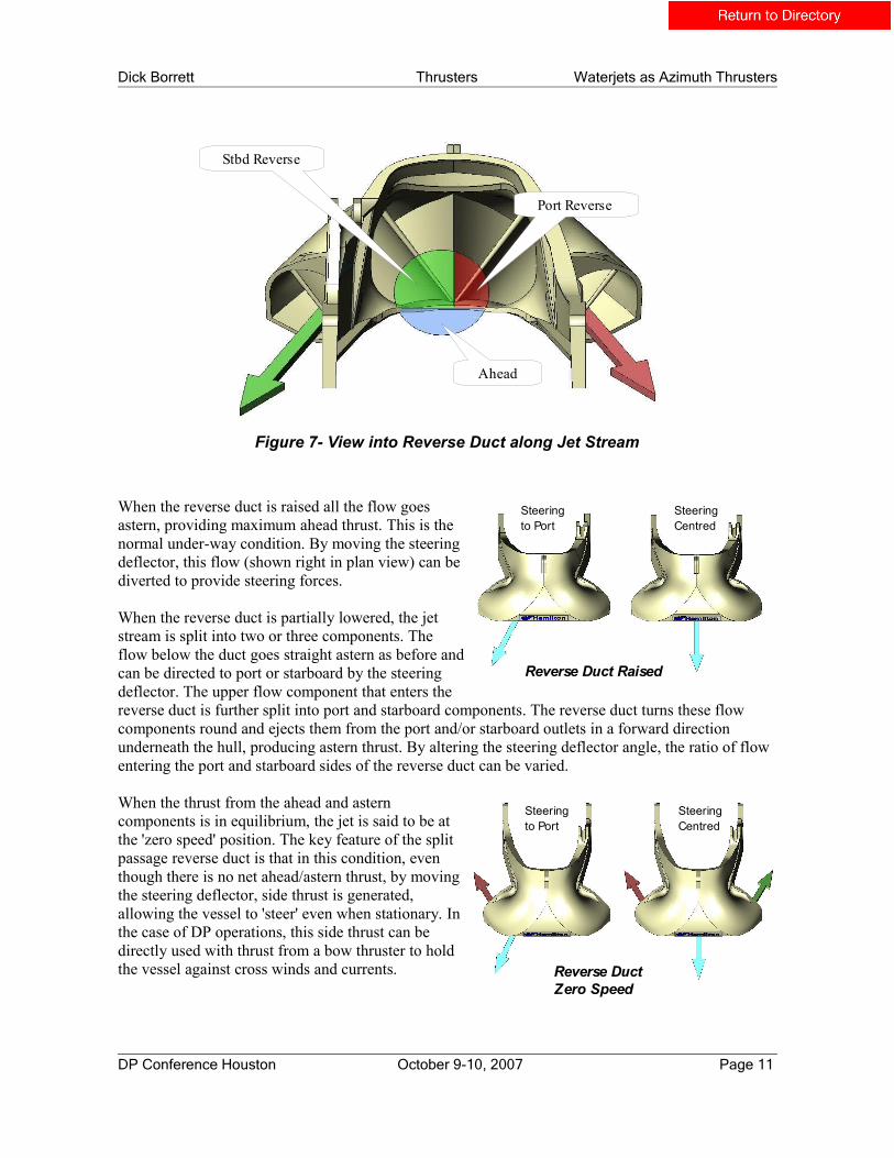
Figure 7 shows a view looking aft along the jet axis into the reverse duct, which is partly lowered into the jet stream. In this view the steering deflector is angled slightly to starboard. The jet stream is split into three components as follows:-
● The 'Ahead' component (blue) which goes underneath the reverse duct.● The 'Port' component (red) which goes into the port side of the reverse duct.● The 'Starboard' component (green) which goes into the starboard side of the reverse duct.
The 'Ahead' component is only acted on by the steering deflector. The volume of flow in this component is dependent on how far the reverse duct is lowered. The remaining flow going into the reverse duct is further split into port and starboard components with the ratio determined by the steering deflector position.
DP Conference Houston October 9-10, 2007 Page 10
(a) (b)
Dick Borrett Thrusters Waterjets as Azimuth Thrusters
Figure 7- View into Reverse Duct along Jet Stream
When the reverse duct is raised all the flow goes astern, providing maximum ahead thrust. This is the normal under-way condition. By moving the steering deflector, this flow (shown right in plan view) can be diverted to provide steering forces.
When the reverse duct is partially lowered, the jet stream is split into two or three components. The flow below the duct goes straight astern as before and can be directed to port or starboard by the steering deflector. The upper flow component that enters the reverse duct is further split into port and starboard components. The reverse duct turns these flow components round and ejects them from the port and/or starboard outlets in a forward direction underneath the hull, producing astern thrust. By altering the steering deflector angle, the ratio of flow entering the port and starboard sides of the reverse duct can be varied.
When the thrust from the ahead and astern components is in equilibrium, the jet is said to be at the 'zero speed' position. The key feature of the split passage reverse duct is that in this condition, even though there is no net ahead/astern thrust, by moving the steering deflector, side thrust is generated, allowing the vessel to 'steer' even when stationary. In the case of DP operations, this side thrust can be directly used with thrust from a bow thruster to hold the vessel against cross winds and currents.
DP Conference Houston October 9-10, 2007 Page 11
Stbd Reverse
Port Reverse
Ahead
Steeringto Port
SteeringCentred
Reverse Duct Raised
Steeringto Port
SteeringCentred
Reverse DuctZero Speed
Dick Borrett Thrusters Waterjets as Azimuth Thrusters
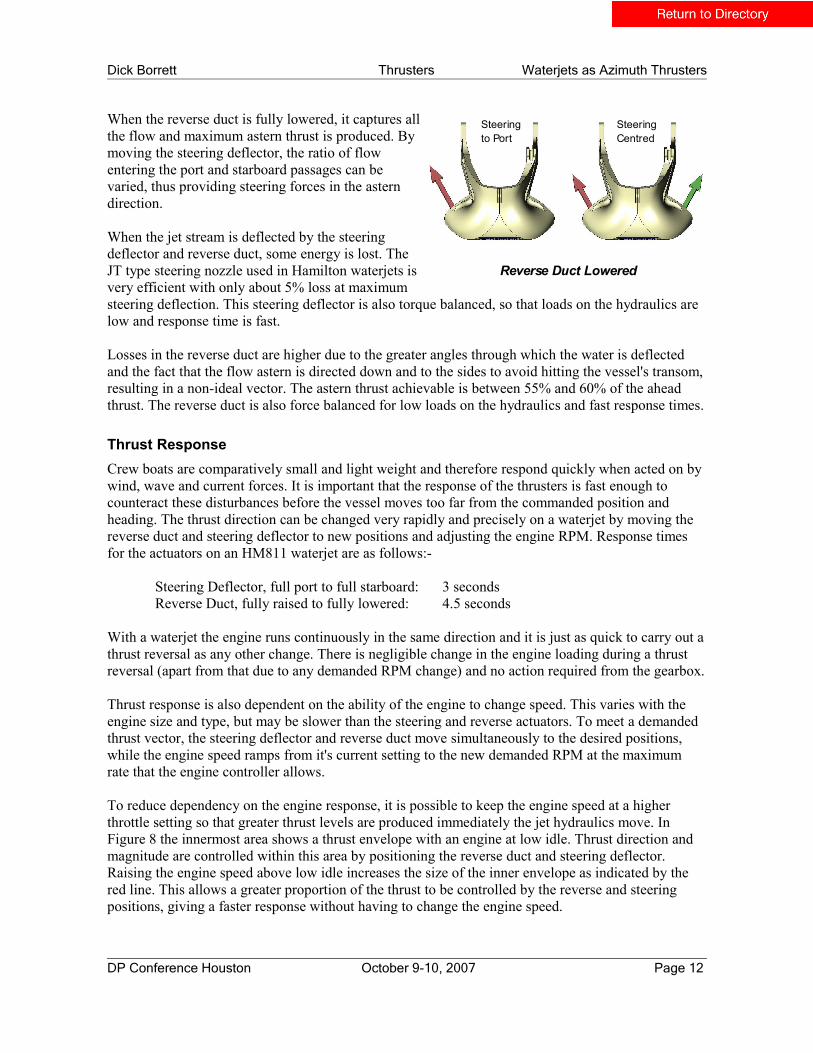
When the reverse duct is fully lowered, it captures all the flow and maximum astern thrust is produced. By moving the steering deflector, the ratio of flow entering the port and starboard passages can be varied, thus providing steering forces in the astern direction.
When the jet stream is deflected by the steering deflector and reverse duct, some energy is lost. The JT type steering nozzle used in Hamilton waterjets is very efficient with only about 5% loss at maximum steering deflection. This steering deflector is also torque balanced, so that loads on the hydraulics are low and response time is fast.
Losses in the reverse duct are higher due to the greater angles through which the water is deflected and the fact that the flow astern is directed down and to the sides to avoid hitting the vessel's transom, resulting in a non-ideal vector. The astern thrust achievable is between 55% and 60% of the ahead thrust. The reverse duct is also force balanced for low loads on the hydraulics and fast response times.
Thrust ResponseCrew boats are comparatively small and light weight and therefore respond quickly when acted on by wind, wave and current forces. It is important that the response of the thrusters is fast enough to counteract these disturbances before the vessel moves too far from the commanded position and heading. The thrust direction can be changed very rapidly and precisely on a waterjet by moving the reverse duct and steering deflector to new positions and adjusting the engine RPM. Response times for the actuators on an HM811 waterjet are as follows:-
Steering Deflector, full port to full starboard: 3 secondsReverse Duct, fully raised to fully lowered: 4.5 seconds
With a waterjet the engine runs continuously in the same direction and it is just as quick to carry out a thrust reversal as any other change. There is negligible change in the engine loading during a thrust reversal (apart from that due to any demanded RPM change) and no action required from the gearbox.
Thrust response is also dependent on the ability of the engine to change speed. This varies with the engine size and type, but may be slower than the steering and reverse actuators. To meet a demanded thrust vector, the steering deflector and reverse duct move simultaneously to the desired positions, while the engine speed ramps from it's current setting to the new demanded RPM at the maximum rate that the engine controller allows.
To reduce dependency on the engine response, it is possible to keep the engine speed at a higher throttle setting so that greater thrust levels are produced immediately the jet hydraulics move. In Figure 8 the innermost area shows a thrust envelope with an engine at low idle. Thrust direction and magnitude are controlled within this area by positioning the reverse duct and steering deflector. Raising the engine speed above low idle increases the size of the inner envelope as indicated by the red line. This allows a greater proportion of the thrust to be controlled by the reverse and steering positions, giving a faster response without having to change the engine speed.
DP Conference Houston October 9-10, 2007 Page 12
Steeringto Port
SteeringCentred
Reverse Duct Lowered

Dick Borrett Thrusters Waterjets as Azimuth Thrusters
Figure 8- Jet Manoeuvring Thrust Variation with Engine Speed
Thrust ResolutionMain drive fixed pitch propellers used with conventional gearboxes for DP operations are limited in their ability to finely control the thrust, since a main drive propeller may produce as much as 40% of the maximum thrust at idle RPM. To obtain a lower thrust level the gearbox would have to be repeatedly clutched in and out – which would give a very slow thrust response and shorten the gearbox life. To overcome this problem, fixed pitch propellers are generally paired to run in opposite directions in a 'push-pull' arrangement.
Slipping clutch gearboxes may be employed to obtain a finer level of control over the thrust although these require additional control and monitoring as well as special cooling arrangements, since power is being dumped as heat. These gearboxes typically allow the thrust to be controlled down to about 5% before full disengagement.
By comparison, waterjets have virtually infinite low level thrust resolution, more comparable to a controllable pitch (CP) propeller. When the engine is at idle speed, control over the thrust is dependent on how accurately the reverse duct and steering deflector are positioned. Thrust resolution down to about 0.2% can be achieved. At higher thrust levels, the resolution is dependent on how accurately the engine speed can be controlled. For example, if engine speed is controlled to within 10 RPM, about 0.7% thrust resolution would be obtained for an HM811 waterjet.
Control System Interfacing and Set UpThe larger Hamilton waterjets currently use the MECS electronic control system which provides steering, reverse, engine speed and gearbox control. A DP Interface Module has been developed which provides simple interfacing between any DP system and the jet control system. Because there is a complex relationship between engine speed, the steering deflector and reverse duct positions and the thrust direction and magnitude, the DP Interface Module has been designed to incorporate these complexities and make the jet 'appear' like an azimuth thruster to the DP system.
DP Conference Houston October 9-10, 2007 Page 13
Maximum Thrust
Thrust with increased RPM
Low Idle Thrust
Dick Borrett Thrusters Waterjets as Azimuth Thrusters
A block diagram showing the interface between the DP system and the jet control system is shown in Figure 9. Jets are treated independently, one DP Interface Module being provided for each waterjet. Each module has two separate interfaces allowing up to DP2 capability. The DP system commands the waterjet to provide a given amount of thrust in a specified direction or azimuth. The DPI module reads these demand signals and calculates the required steering and reverse positions and engine speed. These demands are transmitted via the CAN bus to the MECS modules that control jet positioning and set the engine RPM demand.
The DPI module also receives steering, reverse and RPM feedback signals from MECS, which it converts back into azimuth and thrust feedback. These signal are fed back to the DP system for monitoring.
When the DP system is in command as indicated via the DP_ENABLED signal, the normal MECS manual controls become disabled. A ‘READY’ signal indicates the status of each jet control system to the DP system. MECS continuously monitors it's operation and in the event of an alarm condition preventing proper control of the waterjet or engine, indicates the problem to the DP system via this signal.
Thus the standard waterjet control system requires only a DP Interface Module to be added for each jet to become an 'azimuth thruster'. Interfacing to the DP system and setting up the MECS system is a quick and straightforward process. Because the waterjet thrust characteristics are well defined and well behaved, set up and commissioning time for the DP system is shortened. Conversely, in crew boats having five main propellers and twin rudders, large quantities of water are being moved by the propellers during manoeuvring, making it difficult to model the vessel response. Effects such as 'prop walk'3 also have to be taken into account and these factors result in more time and complexity in setting up the DP system.
Because each waterjet has a fully independent electronic control system, and typically four waterjets are used, the complete thruster system has an inherent high level of redundancy. The fact that the jets do not need to operate in a 'push-pull' arrangement can mean less drastic thruster re-allocation in the event of a failure.
DP Conference Houston October 9-10, 2007 Page 14

Dick Borrett Thrusters Waterjets as Azimuth Thrusters
Figure 9- DP Interface to Jet Control System
Differences between Waterjets and Azimuth ThrustersWhile waterjets can provide similar characteristics to azimuth thrusters, this does not necessarily mean that they should be used in the same way. The following differences should be considered in any DP control scheme:-
Where azimuth thrusters are mounted close to one another, there are certain sectors that must be avoided because thrust is lost if one thruster directs the flow of water directly into another thruster. This problem is largely avoided with waterjets because the directions of the flow components under the vessel are fixed.
Fixed pitch thrusters are invariably operated so as to minimise the need to reverse the thrust direction, as this can be quite a slow process. This often means that thrusters are set up in pairs to produce opposing forces so that the resultant force can change direction without individual thrusters changing direction. This arrangement may not be necessary with waterjets as they can individually change thrust rapidly in any direction required. In this respect they are more like an azimuth thruster fitted with a controllable pitch propeller.
When changing the thrust direction by a large amount, an azimuth thruster may generate unwanted vectors while slewing. This does not occur with the waterjet.
DP Conference Houston October 9-10, 2007 Page 15
Dick Borrett Thrusters Waterjets as Azimuth Thrusters
Methods for Generating Transverse ThrustWaterjets operate in conjunction with one or more bow thrusters under control of the DP system*. The thrusters must provide surge, sway and yaw control forces and moments to maintain the vessel position and heading. Crew boats have a surplus of available surge thrust, and yaw moments are relatively easy to generate due to the long moment arm between the bow thruster and jets when working in opposition. The limiting factor is in the thruster systems ability to create transverse thrust to hold station in cross flow currents and wind.
Using data for the 'Joyce McCall', an analysis has been carried out to compare three different methods of achieving transverse thrust - as detailed below. It has been assumed that the current and wave drift forces act at the vessel mid point (centre of rotation) while the wind forces act 3 metres ahead of this point in the same direction. A wind speed of 10 knots has been used.
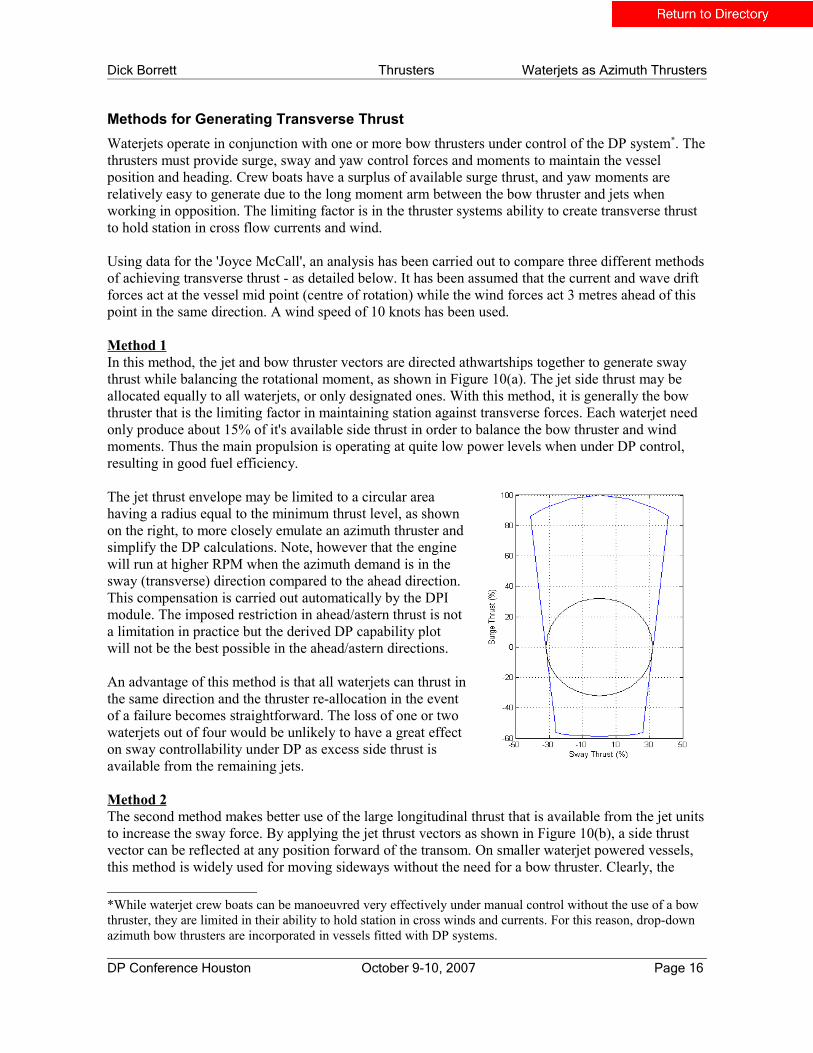
Method 1In this method, the jet and bow thruster vectors are directed athwartships together to generate sway thrust while balancing the rotational moment, as shown in Figure 10(a). The jet side thrust may be allocated equally to all waterjets, or only designated ones. With this method, it is generally the bow thruster that is the limiting factor in maintaining station against transverse forces. Each waterjet need only produce about 15% of it's available side thrust in order to balance the bow thruster and wind moments. Thus the main propulsion is operating at quite low power levels when under DP control, resulting in good fuel efficiency.
The jet thrust envelope may be limited to a circular area having a radius equal to the minimum thrust level, as shown on the right, to more closely emulate an azimuth thruster and simplify the DP calculations. Note, however that the engine will run at higher RPM when the azimuth demand is in the sway (transverse) direction compared to the ahead direction. This compensation is carried out automatically by the DPI module. The imposed restriction in ahead/astern thrust is not a limitation in practice but the derived DP capability plot will not be the best possible in the ahead/astern directions.
An advantage of this method is that all waterjets can thrust in the same direction and the thruster re-allocation in the event of a failure becomes straightforward. The loss of one or two waterjets out of four would be unlikely to have a great effect on sway controllability under DP as excess side thrust is available from the remaining jets.
Method 2The second method makes better use of the large longitudinal thrust that is available from the jet units to increase the sway force. By applying the jet thrust vectors as shown in Figure 10(b), a side thrust vector can be reflected at any position forward of the transom. On smaller waterjet powered vessels, this method is widely used for moving sideways without the need for a bow thruster. Clearly, the
*While waterjet crew boats can be manoeuvred very effectively under manual control without the use of a bow thruster, they are limited in their ability to hold station in cross winds and currents. For this reason, drop-down azimuth bow thrusters are incorporated in vessels fitted with DP systems.
DP Conference Houston October 9-10, 2007 Page 16

Dick Borrett Thrusters Waterjets as Azimuth Thrusters
further forward the transverse thrust is 'aimed', the less effective it becomes, as the angle between the jet vectors gets closer to 180 degrees, reducing the resultant side thrust. The method is more effective on smaller vessels and catamarans, which have smaller length/beam ratios, and it may also be useful where bow thruster power is limited.
Figure 10- Transverse Thrust Methods for Quadruple Waterjets
An optimum transverse thrust solution for this method may be derived by balancing moments from the wind, bow thruster and waterjets around the centre of rotation.
In Figure 10(b) the maximum side force with balanced moments is produced when:
The bow thruster is at maximum load Lf . Tf = La . Ta + wind moment Ta is maximised.
DP Conference Houston October 9-10, 2007 Page 17
Dick Borrett Thrusters Waterjets as Azimuth Thrusters
Calculation of the sway forces using this method show that approximately 35% more side thrust is obtained than with method 1. This may be a useful increase when operating near the extremes of a vessels' DP capability, however it does require much higher power levels from the main propulsion.
Method 3The previous method requires that the thrust level from the port jets is balanced with that from the starboard jets in order to produce a side force without any longitudinal component. Because the 'astern' jets (starboard side in the figure) can only create approximately 60% of the ahead thrust at maximum power, 40% of the available thrust from the 'ahead' jets is unused.
Method 3 provides a way of utilising this additional 'untapped' thrust and is illustrated in Figure 10(c). In this method, the port inner jet is used to generate side thrust and balance the moment from the bow thruster and wind. The remaining three jets are then used to create a side thrust vector that is aimed at the vessel centre of rotation, so that a side force, but no moment is generated. The starboard inner and outer jets both thrust astern at the required azimuth and their combined longitudinal thrust is balanced by the port outer jet that thrusts ahead. This means that maximum ahead thrust on the port outer jet can be used, since the longitudinal forces are being balanced by two jets thrusting astern. Calculation of the forces for this method gives a side thrust virtually the same as method 2. This method may provide more flexibility in thrust allocation for the surge and yaw axes.
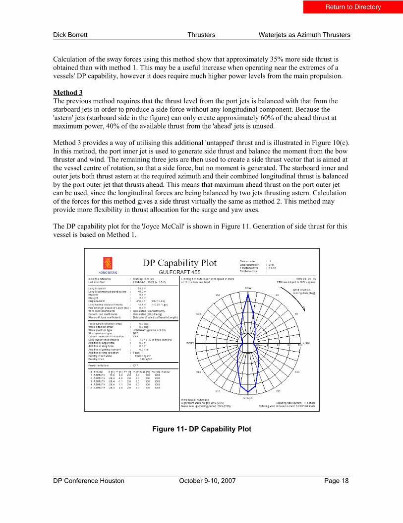
The DP capability plot for the 'Joyce McCall' is shown in Figure 11. Generation of side thrust for this vessel is based on Method 1.
Figure 11- DP Capability Plot
DP Conference Houston October 9-10, 2007 Page 18

Dick Borrett Thrusters Waterjets as Azimuth Thrusters
Conclusions
Waterjets provide an excellent solution for main drive propulsion for vessels operating with varying loads. When running light, more engine power can be absorbed to obtain higher speeds. Waterjets are able to switch modes and effectively emulate an azimuth thruster for DP manoeuvring. Though not as efficient as a dedicated thruster, the use of the main engines provides high thrust for DP manoeuvring. In some respects, the waterjet may surpass the performance of an azimuth thruster in terms of the thrust resolution, speed of response and reduced interaction between adjacent thrusters.
Waterjets used as thrusters may allow control strategies that are not applicable to other thruster types and some of these alternatives have been outlined. Different vessel types such as catamaran crew boats may benefit from these methods to further improve DP operations.
References
1. Alexander, K. (1995). Waterjet versus Propeller Matching Characteristics. Naval Engineers Journal, May 1995, 129-139.
2. Lundquist, E. (2007). Seacor Cheetah Moves to the Head of Class. Maritime Reporter & Engineering News, April 2007, 28 – 32.
3. Moen, Lars, K. (2004). Crew Boat Station Keeping – Challenges and Solutions. Dynamic Positioning Conference - Workboats/OSVs, September 2004.
4. Bekker, Joe, R. Is a Drop-Down Better Than a Tunnel Thruster? http://www.thrustmastertexas.com/applications/dropDownBetterThanTunnelThruster.html
Our thanks to Gulf Craft,Inc., Kongsberg Maritime and Beier Radio for the information that they contributed towards this paper.
DP Conference Houston October 9-10, 2007 Page 19