use of gml for aviation data - open geospatial...
TRANSCRIPT

Open Geospatial Consortium Inc.
Date: July 2011Sep 2011
Reference number of this document: OGC 11-060
Editors: OGC Aviation Domain Working Group
Use of GML for aviation data
Target: Public OGC Discussion Paper after the TC meeting in Brussels (end NOV)
Copyright © 2011 Open Geospatial Consortium, Inc. All Rights Reserved.To obtain additional rights of use, visit http://www.opengeospatial.org/legal/.
Warning
This document is not an OGC Standard. This is an OGC Discussion Paper and is therefore not an official position of the OGC membership. It is distributed for review and comment. It is subject to change without notice and may not be referred to as an OGC Standard. Further, an OGC Discussion Paper should not be referenced as required or mandatory technology in procurements.
Recipients of this document are invited to submit, with their comments, notification of any relevant patent rights of which they are aware and to provide supporting documentation.

Use of GML for aviation data
1 Introduction.....................................................................................................11.1 Objective.....................................................................................................11.2 Scope – Applicability..................................................................................11.3 References...................................................................................................11.4 Interpretation...............................................................................................1
2 Geographical data in Aeronautical Information..............................................2
3 WGS-84...........................................................................................................33.1 Use of srsName...........................................................................................33.2 Use of global srsName................................................................................4
4 Positions...........................................................................................................64.1 Background.................................................................................................64.2 GML encoding............................................................................................6
5 Lines and Surfaces...........................................................................................85.1 Background.................................................................................................85.2 GML encoding............................................................................................9
5.2.1 Straight lines...........................................................................................95.2.2 Parallels................................................................................................105.2.3 Arc by edge...........................................................................................115.2.4 Arc by centre point...............................................................................125.2.5 Circle by center point...........................................................................215.2.6 Corridor................................................................................................215.2.7 Perimeter encoding direction................................................................225.2.8 Other geometries – for procedure design.............................................24
6 Airspace aggregation.....................................................................................256.1 Background...............................................................................................256.2 GML encoding..........................................................................................25
6.2.1 By reference..........................................................................................266.2.2 By copying the geometry......................................................................266.2.3 Combined method.................................................................................27
7 Point references and annotations...................................................................287.1 Background...............................................................................................287.2 GML encoding..........................................................................................29
7.2.1 Using aixm:Point annotations...............................................................297.2.2 Using xlink:href....................................................................................30
8 Geographical border references.....................................................................348.1 Background...............................................................................................348.2 GML encoding..........................................................................................35
8.2.1 Using aixm:Curve annotations.............................................................358.2.2 Using xlink:href....................................................................................37
9 AIXM-GML Profile......................................................................................41
ii Copyright © 2011 Open Geospatial Consortium, Inc. All Rights Reserved.

Use of GML for aviation data
10 Interpolation and Densification Considerations............................................4410.1 Background...............................................................................................44
10.1.1 Comparison of models..........................................................................4410.2 Mapping of GML to Simple Geometry.....................................................45
10.2.1 Flattening of geometry structure...........................................................4510.2.2 Densification of curves.........................................................................4510.2.3 Loss of data structure............................................................................47
Annex A - ArcByCenterPoint Interpretation Summary.............................................48
Annex B – GML change request – support arbitrary rhumblines.............................57
Annex C – Considerations about interpolations........................................................58
Annex D – Offset Curve and Airspace Corridor encoding issues.............................61
Copyright © 2011 Open Geospatial Consortium, Inc. All Rights Reserved. iii

Use of GML for aviation data
i. Preface
This paper provides guidelines for some aspects of the GML encoding that are specific to the aviation data domain.
ii. Document terms and definitions
This document uses the standard terms defined in Subclause 5.3 of [OGC 05-008], which is based on the ISO/IEC Directives, Part 2. Rules for the structure and drafting of International Standards. In particular, the word “shall” (not “must”) is the verb form used to indicate a requirement to be strictly followed to conform to this standard.
iii. Document contributor contact points
All questions regarding this document should be directed to the editor or the contributors:
Name Role OrganizationDavid Burggraf Contributor Galdos, Inc.
Eddie Curtis Contributor Snowflake SoftwareWarwick Dufour Contributor Avitech AG
Johannes Echterhoff Contributor iGSIDavide Castagni Fabbri Contributor IDS Ingegneria Dei Sistemi S.p.A
Benoit Geffroy Contributor EgisAviaFrancois Germain Contributor Thales
Razvan Guleac Contributor EUROCONTROLAlain Kabamba Contributor Erdas
Michal Kadlec Contributor Avitech AGAntonio Locandro Contributor COCESNA
Eduard Porosnicu Editor EUROCONTROLBert Robben Contributor Luciad
Scott Wilson Contributor EUROCONTROL
Anyone missing?? ??? ???
iv Copyright © 2011 Open Geospatial Consortium, Inc. All Rights Reserved.

OpenGIS® Discussion Paper Use of GML for aviation data
1 Introduction
1.1 Objective
The AIXM 5.1 schema uses Geographical Markup Language (GML) version 3.2.1 for the encoding of positional and shape data of aeronautical information items, such as airspace, runway thresholds, navaids, etc.
The ISO 19107 spatial schema, which is implemented by GML, is very complex. It contains an extensive list of geometries, geometric properties and operations – many of which are not necessary for aeronautical information applications. In addition, the ISO 19107 contains an exhaustive 3D geometry model that is probably not needed in its entirety for AIXM either. Therefore, a GML profile for AIXM needs to be defined. The objective of this document is to identify the elements of the AIXM-GML profile and also to provide guidelines for the use of GML constructs in AIXM data sets.
1.2 Scope – Applicability
The discussion paper focuses on guidelines for a aeronautical data encoding using the Aeronautical Information Exchange Model (AIXM).
1.3 References
[1] ICAO Annex 15 (13th Edition) – Aeronautical Information Services
[2] ISO 19107:2003 – Geographic information — Spatial schema
[3] ISO 19136:2007 – Geography Markup Language
[4] OGC 07-092r3 - Definition identifier URNs in OGC namespace
[5] OGC 06-042 - OpenGIS® Web Map Server Implementation Specification
[6] EAD AIXM4.5-to-5.1_Mapping.doc
[7] EAD AIXM 5.1 Conceptual Manual 0.2.doc
1.4 Interpretation
The following definitions shall apply:
‘data set’ means identifiable collection of data
Copyright © 2011 Open Geospatial Consortium, Inc. All Rights Reserved. 1

OpenGIS® Discussion Paper Use of GML for aviation data
2 Geographical data in Aeronautical Information
According to the ICAO rules, Aeronautical Information (AI) is published by States using paper (and increasingly electronic) documents, such as AIP, charts, manuals. This data frequently includes geographically related information items, such as:
Positions expressed in latitude/longitude, which according to ICAO Annex 15 shall be with reference to the WGS-84 datum;
Shapes of airspace, expressed as series of positions in combination with arcs of circles or as full circles; sometimes, these contain references to national borders, water courses, etc., which are not provided explicitly in the AIP;
More recently, shapes of obstacles, provided as point, line or polygon, again using series of positions and arcs of circle.
The Aeronautical Information Exchange Model (AIXM) is used since 2003 for the provision of AI in digital format. Initially developed for the European AIS Database, AIXM is being progressively adopted by other States world-wide, also encouraged by the ICAO work towards the adoption of AIXM as ICAO Guidance Material, through the AIS-AIM Sub Group (http://www2.icao.int/en/ais-aimsg/Lists/Meetings/AllItems.aspx).
The AIXM versions up to 4.5 used a custom XML encoding, not based on OGC standards. Since 2008, with the publication of version 5, the AIXM specification has embraced GML as data encoding format.
There are a number of specificities in the AI Domain that concern the provision of geographical and geometrical information. These are discussed in this document, which also includes recommendations for data encoding in GML.
Copyright © 2011 Open Geospatial Consortium, Inc. All Rights Reserved. 2

Use of GML for aviation data
3 WGS-84
According to ICAO Annex 15, all “published aeronautical geographical coordinates (indicating latitude and longitude) shall be expressed in terms of the WGS-84 geodetic reference datum”.
3.1 Use of srsName
In GML, the geodetic datum is specified by reference to a Coordinate Reference System (CRS). A CRS relates a coordinate system to the earth by a datum. A geodetic datum consists of an ellipsoid model and a prime meridian. The intersection of the equator and prime meridian is the origin of the CRS.
U
M (earth model)
coordinate chart
U
M (earth model)
U
M (earth model)
coordinate chart
V
Coordinate System
V
Coordinate System
f
coordinate mapping
f
coordinate mapping
A geodetic CRS (e.g. EPSG 4326) relates a (lat,lon) ellipsoidal coordinate system to the Earth.
M (earth model)
Domain of validity
M (earth model)
Domain of validity
f
coordinate mapping
f
coordinate mapping
Ellipsoidal Coordinate System
The CRS reference is critical for the correct encoding and processing of the geographical data contained in AIXM/GML files. It indicates not only the geodetic reference datum, but also the order of the coordinate axes (latitude/longitude or
Copyright © 2011 Open Geospatial Consortium, Inc. All Rights Reserved. 3

Use of GML for aviation data
longitude/latitude) and has important implications for the convention used for measuring angles (from the North, clockwise, for example). This will be discussed in more detail, later in this document.
There are two main CRS definition authorities that are relevant for the AI domain: Oil and Gas Producers (OGP), formerly known as the European Petroleum Survey Group (EPSG) and OGC themselves. The two sets of CRS definitions have many common points. For example, the OGC:CRS84 is a variant of EPSG:4326 (differing only in its coordinate order: longitude/latitude) and is defined in the ISO 19128 Geographic information — Web Map Server standard. The EPSG CRS database is available at http://www.epsg.org - European Petroleum Survey Group Geodesy Parameters [EPSG CRS].
Because of the way that angle directions are measured in the AI domain (North corresponds to 0°, East to 90°, etc.), the OGC:CRS 84 is not appropriate for AIXM 5.1/GML data sets that contain arcs of circle defined by start angle/end angle. This will be explained in section 5.2.4.1 of this document. Therefore, it is generally recommended that the EPSG:4326 CRS is used in AIXM 5.1 data sets, which use the WGS-84 reference datum required by ICAO. However, this does not exclude the use of other CRS when appropriate.
Recommendations for the use of CRS references in GML data sets are provided in the OGC Recommendation Paper “URNs of definitions in ogc namespace” [OGC URN], which provides the following URN identifier for the EPSG:4326 CRS: urn:ogc:def:crs:EPSG::4326.
When applied to the encoding of a surface in AIXM, this will give the following GML element:
<aixm:Surface gml:id="S01" srsName="urn:ogc:def:crs:EPSG::4326">
Note that it is not required to also specify the srsDimension attribute, because it is implicit from the srsName. Specifying the srsDimension could lead to discrepancies, such as using srsName=”epsg:4326” and srsDimension=”3”. People might think that this is a good way to describe 3D WGS84 coordinates. But this is wrong and an appropriate 3D srsName should be used in that case, such as EPSG::4979.
3.2 Use of global srsName
For all geometries (Surface, ElevatedPoint, etc.) a CRS must be specified. The CRS is either defined directly on the geometry element using the srsName attribute or it is derived from the larger context this geometry is part of.
For convenience in constructing feature and feature collection instances, the value of the srsName attribute on the gml:Envelope shall be inherited by all directly expressed geometries in all properties of the feature or members of the collection, unless overruled by the presence of a local srsName. The gml:Envelope is a child element of the
4 Copyright © 2011 Open Geospatial Consortium, Inc. All Rights Reserved.

Use of GML for aviation data
gml:boundedBy property of the feature, as indicated in Figure 1. Thus it is not necessary for a geometry to carry a srsName attribute, if it uses the same coordinate reference system as given on the gml:boundedBy property of its parent feature.
Inheritance of the coordinate reference system continues to any depth of nesting, but if overruled by a local srsName declaration, then the new coordinate reference system is inherited by all its children in turn.
Notwithstanding this rule, all the geometries used in a feature or feature collection may carry srsName attributes, in order to indicate the reference system used locally, even if they are the same as the parent. A geometry without srsName derives its CRS from its closest ancestor that has an srsName. Because of the way that AIXM is built, this can only be one of the following:
aixm:Surface aixm:Curve aixm:Point
If no such ancestor is found, it derives its CRS from the srsName of the gml:Envelope in the boundedBy element of the feature or feature collection in which the geometry is contained. Geometries for which no CRS can be derived are invalid.
Figure 1 - Global srsName specified using gml:Envelope
Copyright © 2011 Open Geospatial Consortium, Inc. All Rights Reserved. 5

Use of GML for aviation data
4 Positions
4.1 Background
Simple positions are used in order to indicate the geographical location of an airport reference point, navaid, waypoint, runway threshold, etc. In AI publications, they are expressed as a pair of latitude/longitude coordinates. The information about the geodetic reference datum is usually not provided for each individual position, being specified once for the whole AIP.
4.2 GML encoding
In AIXM 5.1, simple positions are encoded using the aixm:Point or aixm:ElevatedPoint elements, which are extensions of the gml:Point, as in the following example:
…
<aixm:ElevatedPoint srsName="urn:ogc:def:crs:EPSG::4326" gml:id="ID55">
<gml:pos>52.2889 -32.0350</gml:pos>
</aixm:ElevatedPoint>
…
Note that the EPSG:4326 CRS has latitude as the primary axis, which indicates that the order of the values in the gml:pos element is first latitude, then longitude. This convention is very important for the correct interpretation of the data and it is not the same for all CRS! For example, the OGC:CRS84 has longitude as the primary axis. Therefore a GML data set that use the OGC:CRS84, the first value in the gml:pos element will indicate the longitude!
The convention “first latitude, then longitude” is widely observed in the AI domain, as it can be seen in the example of the prohibited area definition from section . Not surprisingly, the WMS specification has a note that reads: “users in the international aviation and marine sectors may expect latitude to be before longitude, and a different coordinate display may have safety implications, especially in an emergency response situation” and “developers of user interfaces for WMSs are cautioned that all references to latitude and longitude, for example user input of bounding box or readout of cursor coordinates, should show latitude before longitude”.
For GML encoding, the latitude/longitude data needs to be expressed in numerical (degrees with decimals) format. If this is not the case with the originator data, a data format conversion should take place. This conversion should be done with a sufficient number of decimal values in order to preserve the original precision of the data. In order to avoid the introduction of small imprecision due to such format conversions, data originators shall be asked to send the data in the raw numerical format (degrees with decimals) that is typically used for survey and geodetic calculations.
6 Copyright © 2011 Open Geospatial Consortium, Inc. All Rights Reserved.

Use of GML for aviation data
For information, note that in the previous AIXM 4.5 version (not based on GML) positional data was encoded using AIXM-defined XML elements, where WGE designates the WGS-84 reference datum:
…
<geoLat>52.2889</geoLat> <geoLong>-32.0350</geoLong> <codeDatum>WGE</codeDatum>
…
Copyright © 2011 Open Geospatial Consortium, Inc. All Rights Reserved. 7

Use of GML for aviation data
5 Lines and Surfaces
5.1 Background
Certain features in the AI domain have polygonal shape (such as Airspace) or linear shape (such as a power line VerticalStructure). They are typically published (for example, in Aeronautical Information Publications – AIP) as a series of latitude/longitude positions, such as in the following example:
EAP 25 (The Castle) 52°11'08.00"N 005°12'30.00"E;52°12'22.00"N 005°17'15.00"E; 52°11'21.00"N 005°17'56.00"E;
52°10'09.00"N 005°17'56.00"E;(then along the parallel to) 52°10'09.00"N 005°13'11.00"E;
to point of origin.
Usually, it is not indicated in the AI source documents what kind of interpolation is used for the curve between the consecutive points, but it is generally assumed that:
If two consecutive points have the same latitude value, then the line connecting the two points is a parallel on the surface of the Earth; this may be explicitly stated using words such as “along the parallel to”;
Otherwise, it is considered a “straight line on the map”.
In addition, the map used when the airspace was designed is typically unknown.
Arcs of circle are also used in the definition of airspace borders, such as in the following examples:
EHR 4A (VLIEHORS) TSA 53°10'12.59"N 004°46'21.14"E; along clockwise arc (radius 8 NM, centre 53°15'00.00"N 004°57'00.00"E) to
53°07'01.98"N 004°56'02.41"E; 53°11'00.00"N 004°51'24.00"E; to point of origin.
EHR 4B (VLIEHORS) 53°09'43.06"N 005°06'58.79"E; 53°02'40.00"N 005°15'00.00"E; 52°58'09.00"N 005°06'22.00"E; 53°07'01.98"N 004°56'02.41"E; along anti-clockwise arc (radius 8 NM, centre 53°15'00.00"N 004°57'00.00"E) to point of origin.
Arcs may also be used in the definition of approach/departure trajectories. However, specific “path and terminator” codes are used to encode such arcs and the use of GML in this case is limited to providing a curve for printing the procedure on a map. GML is not used to encode the real flight trajectory of an aircraft, as stored in the Flight Management System (FMS).
8 Copyright © 2011 Open Geospatial Consortium, Inc. All Rights Reserved.

Use of GML for aviation data
5.2 GML encoding
5.2.1 Straight lines
It is recommended that gml:GeodesicString is used as default encoding for straight lines, for the following reasons:
a geodesic interpolation is the mathematical generalization of the notion of “straight line” on the surface of the Earth;
the result of the interpolation on the surface of the Earth does not depend on the CRS used; by contrast, a linear interpolation would result on different curves on the surface of the Earth, depending on the CRS used (in fact, this will be exploited in order to encode lines along a parallel, see further down).
Surfaces are encoded in GML using gml:PolygonPatch elements. The pairs of lat/long coordinates can be encoded as either a sequence of gml:pos or, more compact, using a gml:posList element: …
<aixm:Surface gml:id="S01" srsName="urn:ogc:def:crs:EPSG::4326"><gml:patches>
<gml:PolygonPatch gml:id=”PP01”><gml:exterior>
<gml:Ring><gml:curveMember>
<gml:Curve gml:id="C001"><gml:segments>
<gml:GeodesicString><gml:posList>52.18556 5.20833 52.20611 5.2875 52.18917 5.29889 52.16917 5.29889 52.18556
5.20833</gml:posList></gml:GeodesicString>
</gml:segments></gml:Curve>
</gml:curveMember></gml:Ring>
</gml:exterior></gml:PolygonPatch>
</gml:patches></aixm:Surface>
…
Note that the first latitude/longitude pair in a posList is equal to the last one, which is mandatory1 for a closed LinearRing in GML. Also note that the same separator (space) is used both between the latitude and longitude values (coordinate separator) and also between the latitude/longitude groups (tuple separator).
1 Note that in GML 3.3 there are new compact encodings for geometry primitives, such as SimplePolygon that do not require the repeated last coordinate. However, these are not available yet in AIXM 5.1, which uses GML 3.2.1.
Copyright © 2011 Open Geospatial Consortium, Inc. All Rights Reserved. 9

Use of GML for aviation data
5.2.2 Parallels
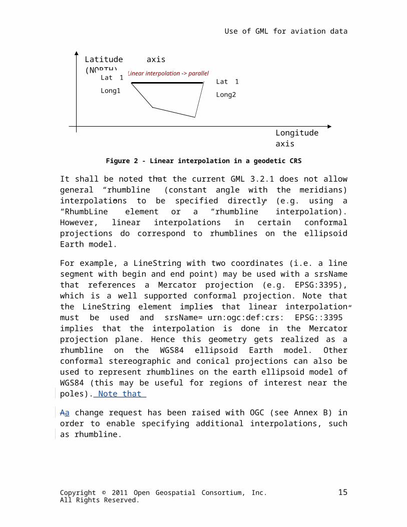
In the AI domain, if an airspace border has two consecutive points at the same geographical latitude, it is assumed that the line between the two points is “along the parallel”. This can be encoded in AIXM/GML using “linear” GML elements in combination with a geodetic CRS, such as EPSG:4326. The linear interpolation in a 2D geodetic CRS between two points that have the same latitude corresponds to a parallel on the Earth’s surface. This is shown graphically in Figure 2.
Figure 2 - Linear interpolation in a geodetic CRS
It shall be noted that the current GML 3.2.1 does not allow general “rhumbline” (constant angle with the meridians) interpolations to be specified directly (e.g. using a “RhumbLine” element or a “rhumbline” interpolation). However, linear interpolations in certain conformal projections do correspond to rhumblines on the ellipsoid Earth model.
For example, a LineString with two coordinates (i.e. a line segment with begin and end point) may be used with a srsName that references a Mercator projection (e.g. EPSG:3395), which is a well supported conformal projection. Note that the LineString element implies that linear interpolation must be used and srsName=”urn:ogc:def:crs: EPSG::3395” implies that the interpolation is done in the Mercator projection plane. Hence this geometry gets realized as a rhumbline on the WGS84 ellipsoid Earth model. Other conformal stereographic and conical projections can also be used to represent rhumblines on the earth ellipsoid model of WGS84 (this may be useful for regions of interest near the poles). Note that
Aa change request has been raised with OGC (see Annex B) in order to enable specifying additional interpolations, such as rhumbline.
In conclusion:
in the classical aeronautical information case of two consecutive points having the same latitude, a gml:LineStringSegment with "default" CRS EPSG:4326 should be used for encoding.
10 Copyright © 2011 Open Geospatial Consortium, Inc. All Rights Reserved.
Linear interpolation -> parallel
Longitude axis
Latitude axis (NORTH)
Lat 1
Long1Lat 1
Long2

Use of GML for aviation data
in the particular case where one wants to express a rhumbline whereas the two consecutive latitudes are different, a gml:LineStringSegment with a "Mercator" CRS like EPSG:3395 can be used.However, this is mostly a theoretical issue since parallels are the only type of rhumbline extensively used in the AI domain. Therefore, it is not considered necessary to support the encoding of rhumblines, other than parallels, in AIXM 5.1.
5.2.3 Arc by edge
This is a relatively simple case as it is represented by the element gml:Arc in GML, which does not have any ambiguities: 3 points always define a single arc. Unfortunately, this is rarely used in the AI domain. When moving towards a fully digital AI chain, the use of this type of arc information should be encouraged and eventually imposed as the unique way for defining arcs. However, this is not likely to be achieved on short term.
A border that uses arcs by 3 points looks like in Figure 3 - Arc by edge point:
Figure 3 - Arc by edge point
A GML encoding example for this type of arcs is provided below.
…
<gml:PolygonPatch> <gml:exterior> <gml:Ring gml:id=”…”>
… <gml:curveMember> <gml:Curve gml:id="…"> <gml:segments> <gml:Arc gml:id=”…”> <gml:pos>P2</gml:pos> <gml:pos>P3</gml:pos> <gml:pos>P4</gml:pos> </gml:Arc> </gml:segments> </gml:Curve> </gml:curveMember> ...
Copyright © 2011 Open Geospatial Consortium, Inc. All Rights Reserved. 11

Use of GML for aviation data
In fact, this is a particular case of the more general GML concept of “ArcString”, which is a curve segment that uses three-point circular arc interpolation in a piecewise fashion to “string” the arc segments together. The number of control points in the string is (2 x numArc)+1, where numArc is the property defining the number of the arcs in the string, such as in Figure 4 - ArcString in ISO 19107
Figure 4 - ArcString in ISO 19107
For information, the AIXM 4.5 way of encoding the arc by edge point using AIXM-defined elements is provided below:
...
<Avx> <codeType>ABE</codeType> <geoLat>lat-P2</geoLat> <geoLong>long-P2</geoLong> <codeDatum>WGE</codeDatum> <geoLatArc>lat-P3</geoLatArc> <geoLongArc>long-P3</geoLongArc></Avx>...
12 Copyright © 2011 Open Geospatial Consortium, Inc. All Rights Reserved.

Use of GML for aviation data
5.2.4 Arc by centre point
Currently, this is the typical construct for arcs used in the definition of airspace borders in the AI domain. It comes with two problems:
The arc is over specified, as the start/end points, the centre and the radius are all provided. Typically, the calculated distance from the centre to the start and end point is not quite the same due to round-off error and is also usually different from the radius;
This construction of arcs is not supported exactly this way in GML and in GIS systems in general.
The closest GML construct that can be used for encoding this type of arcs is ArcByCenterPoint. This requires calculating the start/end angles from the centre to the start/end points. Before calculating these angles, it is important to specify the angle measuring convention in AIXM, as GML seems to leave some degree of interpretation for this aspect.
5.2.4.1 Measuring angles in GML
GML explicitly implements2 the semantics of ISO 19107. The “startOfArc” (6.4.15.5) and “endOfArc” (6.4.15.6) are defined in terms of bearings. The definition of “bearing” is provided in Section 6.3.12, which states that “Bearing is a data type used to represent direction in the coordinate reference system. In a 2D coordinate reference system, this can be accomplished using a “angle measured from true north” or a 2D vector point in that direction.”
There are two variants mentioned in ISO 19107 for expressing bearings: angle and direction. The semantics for angle is given in 6.3.12.2 of the same document: “In this variant of Bearing usually used for 2D coordinate systems, the first angle (azimuth) is measured from the first coordinate axis (usually north) in a counterclockwise fashion parallel to the reference surface tangent plane.”
Although it may not be obvious, this definition matches the needs of the AI domain, as angles are usually expressed in degrees measured clockwise from the True North. The diagrams below explain why the “counter clockwise” convention stated in the ISO 19107 standard, when combined with the EPSG:4326 geodetic CRS actually corresponds to a clockwise rotation in the AI domain.
2 Note that this is true for classes of spatial primitives (e.g. GM_Arc) but in general not their operations. In the ISO 19107, startOfArc and endOfArc are operations, aka constructors which derive other values from the GM_Arc. However, GML/ISO 19136 defines the UML Class ArcByCenterPoint (Figure D.48) in a GML profile of ISO 19107 where startOfArc and endOfArc are attributes. Although not explicitly stated in the GML standard, we can infer that the ISO 19107 semantics for operations carry over to the identical semantics for the corresponding attributes with the same name in the GML profile of ISO 19107 (ISO 19136, Annex D).
Copyright © 2011 Open Geospatial Consortium, Inc. All Rights Reserved. 13

Use of GML for aviation data
Figure 5 - Angle measured in a 2D geodetic CRS that has latitude as first axis
In the EPSG:4326 CRS, the first (x) axis is latitude and the second (y) axis is longitude. A counter clockwise angle means measuring it from the first axis towards the second axis. When transposing this coordinate system on the surface of the Earth, this corresponds to a clockwise rotation from the first axis (North) in order to measure angles, as shown in Figure 6. Practically, the x/y reference system is mirrored and rotated to be aligned with the meridians and the parallels.
Figure 6 - Coordinate System Axes of EPSG:4326 CRS mapped on the Earth's surface
Therefore, when the EPSG:4326 CRS (or another 2D geodetic CRS that has latitude as first axis) is used, this translates to angles that are measured clockwise starting from the True North in the AI Domain. East is at 90 degrees from North, South at 180 degrees from North, etc. This convention is important for defining the startAngle and endAngle of the ArcByCenterPoint. Note that it is also possible to use negative values for angles. Negative angles are measured from the first axis through rotation in the direction opposite to the second axis.
The following diagram shows how angles are measured in WGS 84 2D with different coordinate systems:
14 Copyright © 2011 Open Geospatial Consortium, Inc. All Rights Reserved.
y
x
Counter clockwise arc
(latitude)
(longitude)
90 degrees
x
y

Use of GML for aviation data
(A) GeodeticCRS: urn:ogc:def:crs:OGC:1.3:CRS84
Datum: WGS84
Ellipsoidal 2D CS.
o Axes: (1st) longitude, (2nd) latitude.
o Orientations: east, north. UoM: degree
(B) GeodeticCRS: urn:ogc:def:crs:EPSG::4326
Datum: WGS84
Ellipsoidal 2D CS.
o Axes: (1st) latitude, (2nd) longitude.
o Orientations: north, east. UoM: degree
The order of the axes determines where 0° is located (on the positive part of the coordinate system's first axis).
5.2.4.2 Arc direction
Once the startAngle and endAngle are known, it is still necessary to establish how the arcs are interpolated/drawn. The semantics of the words “start” and “end” indicate that arcs shall be interpolated/drawn from the start angle to the end angle, similarly to a line that is always interpolated/drawn from its start to its end. However, this still leaves some room for interpretation, e.g. an arc that has startAngle=90 (East) and endAngle=180 (West) should be interpolated/drawn through South or through North?
The following convention shall apply in the aviation domain: if the start angle is smaller than the end angle then the arc direction is the direction in which the angle values increase. If the opposite is true, than the arc direction is the one in which the angle values decrease. Depending upon the coordinate system that applies to a given ArcByCenterPoint, this results in a clockwise (left-handed system) or counter-clockwise
Copyright © 2011 Open Geospatial Consortium, Inc. All Rights Reserved. 15
Use of GML for aviation data
(right-handed system) directed arc. The arguments for this convention are detailed in Annex A.
Applied with the EPSG:4326 CRS, this means that arcs are drawn:
clockwise on the surface of the Earth when the startAngle is lower than the endAngle;
counter-clockwise on the surface of the Earth when the startAngle is higher than the endAngle
The same convention applies to any other geodetic CRS that has latitude as first (x) axis. This is exemplified in Figure 7. It is therefore possible to define arcs in both clockwise and counter-clockwise direction by choosing the right startAngle and endAngle values. This also requires the use of angle values between -360 and 360, both values included.
16 Copyright © 2011 Open Geospatial Consortium, Inc. All Rights Reserved.
Use of GML for aviation data
endAngle(e.g. 15º)
startAngle (e.g. 80º)
P4
P3
P1
P2
startAngle(e.g. -15º)
endAngle (e.g. 80º)
P2
P3
P1
P4
Example 1 – clockwise arc(start angle < end angle)
Example 2 – counter-clockwise arc(start angle > end angle)
CRS: EPSG:4326
Figure 7 - Arcs are drawn clockwise, from startAngle to endAngle in the AI convention (as illustrated in Figure 6)
5.2.4.3 Arc interpolation
Typically, there are no statements in AI sources, such as State AIP, about how arcs and circles should be interpolated. Such arcs are usually designed using a map (into a specific projection, which is not communicated). Thus, they would represent points of equal distance from the arc centre, on that specific projection. Considering that the airspace design processes always include buffers in the definition of an area that contains a dangerous activity, the relative imprecision of an arc or circle interpolation is not operationally significant. However, it is important to have a common interpretation of how arcs and circles should be interpolated when defined in GML “by center point”.
Copyright © 2011 Open Geospatial Consortium, Inc. All Rights Reserved. 17
startAngle = 10º
Latitude axis (NORTH)
Longitude axis (EAST)
endAngle = 150º
startAngle = 10º
endAngle = -210º
CRS: EPSG:4326

Use of GML for aviation data
Therefore, it is recommended to interpolate ArcByCentrePoint through points situated at equal geodesic distance (the radius if the arc) from the arc centre. This makes the interpolation independent of the CRS used.
5.2.4.4 Mapping for ArcByCenterPoint
This section indicates how to calculate the start/end angles when the information provided by the (official) source is in the form of start/end positions, centre and radius. The situation presented in Figure 8 exemplifies a part of an Airspace boundary that is a sequence of:
a straight segment (P1-P2) followed by a clockwise arc from P2 to P4 with the centre in P3 followed again by a straight line to P5.
P1
P2
P3
P4rad
ius
P5
Figure 8 - Mapping arc by start/end point into ArcByCenterPoint
Sometimes, the arc drawn using the exact centre points and radius value provided by the originator does not exactly match. The radius is usually a rounded value, which may be different up to 10% from the calculated distances from the centre P3 to points P2 or P4. However, as one objective of the GML encoding is to preserve as much as possible the original (official) information, it is recommended that the original centre and radius data is used directly for the ArcByCenterPoint in the AIXM/GML encoding. The startAngle shall be calculated using the vector P3-P2 and the endAngle shall be calculated using the vector P3-P4. The resulting arc is represented in Figure 9. This shows that it is possible that the resulting GML arc does not align at points P2 and P4, because of the imprecision of the original centre and/or radius data.
18 Copyright © 2011 Open Geospatial Consortium, Inc. All Rights Reserved.

Use of GML for aviation data
startAngle
endAngleP1
P2
P3
P4rad
ius
Figure 9 - Calculating startAngle and endAngle for ArcByCenterPoint
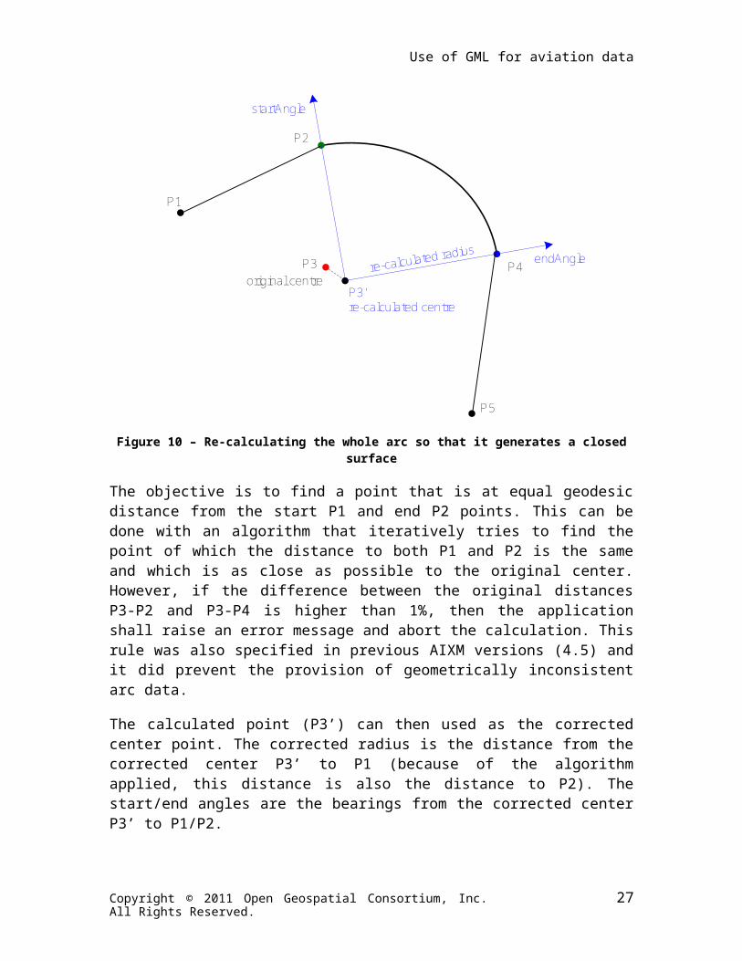
If the potential misalignment of the arc (as indicated in Figure 9) is a problem for an application, then it is suggested that, for example, the original centre and radius data are replaced with calculated values, by that application, as indicated in Figure 10.
re-calculated radius
startAngle
endAngle
original centreP3' re-calculated centre
P2
P3 P4
P1
P5
Figure 10 – Re-calculating the whole arc so that it generates a closed surface
Copyright © 2011 Open Geospatial Consortium, Inc. All Rights Reserved. 19

Use of GML for aviation data
The objective is to find a point that is at equal geodesic distance from the start P1 and end P2 points. This can be done with an algorithm that iteratively tries to find the point of which the distance to both P1 and P2 is the same and which is as close as possible to the original center. However, if the difference between the original distances P3-P2 and P3-P4 is higher than 1%, then the application shall raise an error message and abort the calculation. This rule was also specified in previous AIXM versions (4.5) and it did prevent the provision of geometrically inconsistent arc data.
The calculated point (P3’) can then used as the corrected center point. The corrected radius is the distance from the corrected center P3’ to P1 (because of the algorithm applied, this distance is also the distance to P2). The start/end angles are the bearings from the corrected center P3’ to P1/P2.
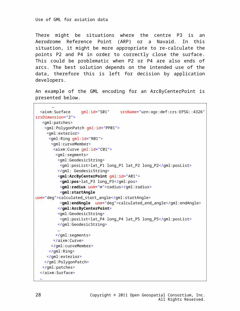
There might be situations where the centre P3 is an Aerodrome Reference Point (ARP) or a Navaid. In this situation, it might be more appropriate to re-calculate the points P2 and P4 in order to correctly close the surface. This could be problematic when P2 or P4 are also ends of arcs. The best solution depends on the intended use of the data, therefore this is left for decision by application developers.
An example of the GML encoding for an ArcByCenterPoint is presented below. …
<aixm:Surface gml:id="S01" srsName="urn:ogc:def:crs:EPSG::4326" srsDimension="2"><gml:patches>
<gml:PolygonPatch gml:id="PP01"><gml:exterior>
<gml:Ring gml:id="R01"><gml:curveMember>
<aixm:Curve gml:id="C01"><gml:segments>
<gml:GeodesicString><gml:posList>lat_P1 long_P1 lat_P2 long_P2</gml:posList>
</gml: GeodesicString><gml:ArcByCenterPoint gml:id="A01">
<gml:pos>lat_P3 long_P3</gml:pos><gml:radius uom="m">radius</gml:radius><gml:startAngle uom="deg">calculated_start_angle</gml:startAngle><gml:endAngle uom="deg">calculated_end_angle</gml:endAngle>
</gml:ArcByCenterPoint><gml:GeodesicString>
<gml:posList>lat_P4 long_P4 lat_P5 long_P5</gml:posList></gml:GeodesicString>…
</gml:segments></aixm:Curve>
</gml:curveMember></gml:Ring>
</gml:exterior></gml:PolygonPatch>
</gml:patches></aixm:Surface>…
20 Copyright © 2011 Open Geospatial Consortium, Inc. All Rights Reserved.
Use of GML for aviation data
5.2.4.5 Units of measurement
The previous XML encoding example also shows recommended values for the uom attributes of gml:radius and gml:start(end)Angle. According to GML section 8.2.3.7, “in an instance document, on elements of type gml:MeasureType the mandatory uom attribute shall carry a value corresponding to either:
a conventional unit of measure symbol,
a link to a definition of a unit of measure that does not have a conventional symbol, or when it is desired to indicate a precise or variant definition.
For common units of measurement, such as meter for distances and degrees for angles, it is recommended that conventional units of measure symbols are used. A Note in the [GML] standard suggests the use of UCUM symbols: “It is recommended that the symbol be an identifier for a unit of measure as specified in the Unified Code of Units of Measure’ (UCUM) (http://aurora.regenstrief.org/UCUM). This provides a set of symbols and a grammar for constructing identifiers for units of measure that are unique, and may be easily entered with a keyboard supporting the limited character set known as 7-bit ASCII.”
The following UCUM “c/s” (case sensitive) values are recommended to be used for gml:radius in AIXM/GML data sets:
m – when the radius is expressed in meters
km – when the radius is expressed in kilometers
[nmi_i] – when the radius is expressed in Nautical Miles
The symbol “deg” is recommended to be used for the uom attribute of gml:startAngle and gml:endAngle elements.
5.2.4.6 Old AIXM 4.5 encoding
For information, the same border using a clockwise arc was encoded in AIXM 4.5 as in the example below:
...
<Avx> <codeType>GRC</codeType> <geoLat>lat-P1</geoLat> <geoLong>long-P1</geoLong> <codeDatum>WGE</codeDatum></Avx><Avx> <codeType>CWA</codeType> <geoLat>lat-P2</geoLat> <geoLong>long-P2</geoLong> <codeDatum>WGE</codeDatum> <geoLatArc>lat-P3</geoLatArc>
Copyright © 2011 Open Geospatial Consortium, Inc. All Rights Reserved. 21

Use of GML for aviation data
<geoLongArc>long-P3</geoLongArc> <valRadiusArc>Radius</valRadiusArc> <uomRadiusArc>NM</uomRadiusArc></Avx><Avx> <codeType>GRC</codeType> <geoLat>lat-P4</geoLat> <geoLong>long-P4</geoLong> <codeDatum>WGE</codeDatum></Avx>...
5.2.5 Circle by center point
Full circles are also used in order to define the geometry of certain airspace in the AI domain. They can be directly encoded using the gml:CircleByCenterPoint. It is quite deep in the structure, as presented in the example below. …
<aixm:Surface gml:id="S001" srsName="urn:ogc:def:crs:EPSG::4326"><gml:polygonPatches>
<gml:PolygonPatch><gml:exterior>
<gml:Ring><gml:curveMember>
<gml:Curve gml:id="CUR001"><gml:segments>
<gml:CircleByCenterPoint numArc="1"><gml:pos>51.01555556 2.57138889</gml:pos><gml:radius uom="[nmi_i]">12</gml:radius>
</gml:CircleByCenterPoint></gml:segments>
</gml:Curve></gml:curveMember>
</gml:Ring></gml:exterior>
</gml:PolygonPatch></gml:polygonPatches>
</aixm:Surface> …
5.2.6 Corridor
Corridors are sometimes used in the definition of airspace geometries. This is done by specifying a centerline and a width or half-width and it is supported in AIXM through the following properties of the AirspaceVolume class:
“width” attribute
“centreline” association with Curve
22 Copyright © 2011 Open Geospatial Consortium, Inc. All Rights Reserved.

Use of GML for aviation data
Curve(from Geometry)
<<object>>
AirspaceVolumeupperLimit : ValDistanceVerticalTypeupperLimitReference : CodeVerticalReferenceTypemaximumLimit : ValDistanceVerticalTypemaximumLimitReference : CodeVerticalReferenceTypelowerLimit : ValDistanceVerticalTypelowerLimitReference : CodeVerticalReferenceTypeminimumLimit : ValDistanceVerticalTypeminimumLimitReference : CodeVerticalReferenceTypewidth : ValDistanceType
<<object>>
0..1
1
+centreline
0..1
hasCorridorShape
The encoding of airspace corridors in this way does not make full use of the GML capabilities. Theoretically, the gml:OffsetCurve, which is an implementation of the GM_OffsetCurve, could be used to encode the corridor shape in GML. However, because of some lack of clarity that exists with regard to GM_OffsetCurve, it is currently not recommended to use OffsetCurve. Further details are presented in Appendix D.If the GML encoding with “buffer” is used, then do not specify the curve/width in the AIXM code.
5.2.7 Perimeter encoding direction
The GML Surface implements ISO 19107 GM_Surface whose exterior boundary must be encoded counter clockwise and any interior boundary encoded clockwise.
For AI Domain applications, this implies that the outside perimeter and any eventual holes shall be encoded as shown in Figure 11. It is unlikely that more than one level of internal patches (rings) would exist for features in the AI Domain.
Figure 11 - Encoding direction for surface boundaries
Copyright © 2011 Open Geospatial Consortium, Inc. All Rights Reserved. 23

Use of GML for aviation data
The direction of “clockwise” and “counter-clockwise” do not depend on the axis order of the given CRS. They just depend on where “up” is. In EPSG:4326, “up” is implied and pointing from the center of the earth outwards. When a surface is viewed from the side where “up” is, then – following ISO 19107 - the exterior boundary of the surface shall be encoded counter-clockwise while the interior shall be encoded clockwise.
Accordingly, the encoding of surface boundaries – counter-clockwise for exterior boundary, clockwise for any interior boundary - is the same in both left- and right-handed systems; see the following figure.
Figure 12 - The boundary encoding is the same in both left- and right-handed systems
Figure 11 shows a surface with two holes, one of which has an arc as part of its boundary. The direction of this arc needs to be in line with the overall orientation of the boundary. This can unambiguously be achieved following the rules laid out in section 5.2.4 and Annex A. The following figure shows some examples where arcs are part of a surface’s boundary.
24 Copyright © 2011 Open Geospatial Consortium, Inc. All Rights Reserved.

Use of GML for aviation data
Figure 13 - arcs and their direction when being part of a surface boundary
5.2.8 Other geometries – for procedure design
“WindSpiral” used in procedure design, but does not have GML correspondent?
“SegmentLocus” -
“ArcLocus”
They might appear in AIXM encodings as “protection areas” for procedure legs.
Copyright © 2011 Open Geospatial Consortium, Inc. All Rights Reserved. 25

Use of GML for aviation data
6 Airspace aggregation
6.1 Background
There are two main ways to describe the geometry of airspace volumes in the AI Domain:
by providing a horizontal border and vertical limits;
by providing a composition rule by which the airspace is defined as a series of unions, intersections, subtractions of other Airspace, such as in the following examples:
o Airspace of type CTR defined as a “circle of 50 NM from which the portion of airspace situated in a neighboring FIR is subtracted”;
o Airspace of type UIR that has “the same horizontal projection as an FIR”, but different vertical limits;
o Airspace of type CTA which is the result of aggregating some Airspace of type SECTOR;
o etc.
The AirspaceVolume class of the AIXM 5 model was designed in order to support the encoding of such aggregated Airspace. Note that the “operation” property of the AirspaceGeometryComponent is used., whichThis steps outside the GML worldmakes this encoding not-directly understandable for a standard GML tool and requires software customisation.
Although GML supports the creation of composite surfaces using “patches”, it is not possible to leave this aggregation to the GML level because the vertical limits of the different components might be different. The possibility of using 3D geometries might be considered in future. Until then, using only 2D GML components requires custom processing of AIXM/GML files in order to correctly represent the result of an airspace aggregation, in particular the use of the operation and operationSequence attributes of the AirspaceGeometryComponent class.
6.2 GML encoding
The model gives the possibility for using several approaches for the encoding of airspace aggregations/dependencies. The use of a particular method, from the ones described further in this section, depends on the intended use of the data.
In order to exemplify these methods, the example of an Airspace of type “CTA” will be used.
26 Copyright © 2011 Open Geospatial Consortium, Inc. All Rights Reserved.

Use of GML for aviation data
6.2.1 By reference
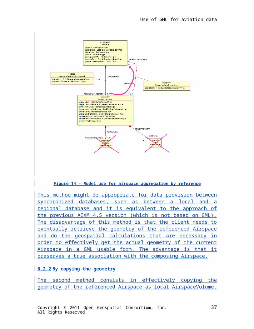
The first method is limited to referring to another airspace, but without effectively copying the geometry of that Airspace as own AirspaceVolume(s). The UML diagram Figure 14 indicates which elements of the AIXM 5.1 model are used or not used when applying this method.
Figure 14 - Model use for airspace aggregation by reference
This method might be appropriate for data provision between synchronized databases, such as between a local and a regional database and it is equivalent to the approach of the previous AIXM 4.5 version (which is not based on GML). The disadvantage of this method is that the client needs to eventually retrieve the geometry of the referenced Airspace and do the geospatial calculations that are necessary in order to effectively get the actual geometry of the current Airspace in a GML usable form. The advantage is that it preserves a true association with the composing Airspace.
Copyright © 2011 Open Geospatial Consortium, Inc. All Rights Reserved. 27

Use of GML for aviation data
6.2.2 By copying the geometry
The second method consists in effectively copying the geometry of the referenced Airspace as local AirspaceVolume. Note that this might be a recursive operation, as the referenced Airspace might have more than one AirspaceVolume and some or even all these could also depend on the geometry of other Airspace.
Figure 15 - Model use for airspace aggregations when copying referenced geometries
This method might be appropriate for applications that need to provide fully digested geometrical data for direct consumption (e.g. graphical visualization, spatial calculations). The disadvantage of this method is that the referenced geometry might also change in time. This is not a problem when the aggregation is used for the provision of Snapshot data (valid at a time instant) but it might become problematic when providing Baseline data (which is valid for a period of time). Future changes of the geometry of referenced airspace needs to be propagated to the AirspaceVolume of the aggregated airspace. The advantage is that this method provides complete geometrical data for the aggregated Airspace and does not require further calculations by the client system.
28 Copyright © 2011 Open Geospatial Consortium, Inc. All Rights Reserved.
Use of GML for aviation data
6.2.3 Combined method
Theoretically, the two methods can be combined.
Copyright © 2011 Open Geospatial Consortium, Inc. All Rights Reserved. 29
Use of GML for aviation data
7 Point references and annotations
7.1 Background
Positions of Navaids or Designated Points may be used in the AI Domain in order to define the shape of an Airspace. They can be used as arc centers or even as boundary points. In the case of NOTAM messages, the latitude/longitude coordinates may be followed by geographical references, such as in the example below.
“E) AIR DISPLAY WILL TAKE PLACE WI LATERAL LIMITS: 443838N 0200818E (NDB OBR) - 444508N 0201455E (VILLAGE JAKOVO) - 443445N 0202447E - 443838N 0200818E (NDB OBR).F) GND G) 3000FT AMSL)”
This is not always a reference to a significant point, it can be simply an annotation of a position (e.g. “Village Jakovo”). However, the encoding solution being quite similar, this case also is discussed here.
This is represented in tThe UML model of AIXM showsas a “dependency” association between Surface and SignificantPoint in order to cater for such situations/GeoBorder:
Surface(from Geometry)
<<object>>
AirspaceVolumeupperLimit : ValDistanceVerticalTypeupperLimitReference : CodeVerticalReferenceTypemaximumLimit : ValDistanceVerticalTypemaximumLimitReference : CodeVerticalReferenceTypelowerLimit : ValDistanceVerticalTypelowerLimitReference : CodeVerticalReferenceTypeminimumLimit : ValDistanceVerticalTypeminimumLimitReference : CodeVerticalReferenceTypewidth : ValDistanceType
<<object>>
0..1
1
+horizontalProjection 0..1
1
hasBoundary
SignificantPoint(from Points)
<<choice>>
Figure 16 - Point references model in AIXM
30 Copyright © 2011 Open Geospatial Consortium, Inc. All Rights Reserved.

Use of GML for aviation data
The reason for using a “dependency” association and not a standard “object to feature association” is that this occurs deep inside the GML encoding of the Surface. Using a “dependency” also indicates that the actual encoding can be done differently, based on the intended use of the data.
7.2 GML encoding
The encoding of point references and annotations can be done using gml:pPointProperty elements, which can appear as a descendant of gml:Curve, for example in the construction of a gml:GeodesicString. Note that the pointProperty allows either referring to another gml:Point (by xlink:href) or providing a gml:Point child element.
According to the GML standard, para 10.2.2.2: “A property that has a point as its value domain may either be an appropriate geometry element encapsulated in an element of this type or an XLink reference to a remote geometry element (where remote includes geometry elements located elsewhere in the same document). Either the reference or the contained element shall be given, but neither both nor none.”
7.2.1 Using aixm:Point annotations
In this case, a gml:pointProperty is used, including an aixm:Point with an annotation (aixm:Note). This encoding has the advantage that the geometry is self-contained (the position of the referenced object is directly copied as a gml:pos element).
This method should be used whenever the data is intended “for human consumption”, such as in the case of the NOTAM examples (e.g. “VILLAGE JAKOVO”). Even in the case when an arc center is located on a DME navaid and the distance information provided by the DME can be used to keep the aircraft inside or outside the arc, the provision of a Point annotation could be sufficient for the end user.
An example is provided below:…
<gml:exterior><gml:Ring>
<gml:curveMember><gml:Curve gml:id="C001">
<gml:segments><gml:GeodesicString>
<gml:posList>52.1855 5.2083 52.2061 5.2875 52.1891 5.2988 52.1691 5.2988</gml:posList></gml:GeodesicString><!-- The next segment contains a point annotation encoded as a Note-->
<gml:GeodesicString><gml:pos>52.16917 5.29889</gml:pos>
<gml:pointProperty><aixm:Point gml:id="P001">
<gml:pos>52.16917 5.21972</gml:pos><aixm:annotation>
<aixm:Note gml:id="N001"><aixm:translatedNote>
<aixm:LinguisticNote gml:id="N002"><aixm:note lang="ENG">VILLAGE JAKOVO</aixm:note>
Copyright © 2011 Open Geospatial Consortium, Inc. All Rights Reserved. 31

Use of GML for aviation data
</aixm:LinguisticNote></aixm:translatedNote>
</aixm:Note></aixm:annotation>
</aixm:Point></gml:pointProperty>
</gml:GeodesicString><!-- This is the final straight segment encoded as a Geodesic, which closes the surface--><gml:GeodesicString>
<gml:posList>52.16917 5.21972 52.18556 5.20833</gml:posList></gml:GeodesicString>
</gml:segments></gml:Curve>
</gml:curveMember></gml:Ring>
</gml:exterior>…
7.2.2 Using xlink:href
When necessary to preserve as a true reference the information that the current position depends on the location of another aeronautical feature, then a gml:PointProperty with a xlink:href attribute can be used. In this case, there shall be no child gml:Point/gml:pos element. The GML standard requires a local reference, using a gml:id value. For compatibility reasons with previous AIXM versions and to satisfy the operational needs of the AI domain, it is also allowed to use a remote reference. The two solutions are detailed here.
7.2.2.1 Local reference to gml:pointPropertygml:Point (or equivalent)
In the example below, the position of the Navaid is used as centre for the circle that defines the horizontal geometry of the Airspace.
<aixm:Navaid gml:id="urn.uuid.791fb712-6c7a-46bb-8e98-49d76942573e"> …
<aixm:type>VOR_DME</aixm:type><aixm:name>DONLON</aixm:name><aixm:location>
<aixm:ElevatedPoint gml:id="P0001" srsName="urn:ogc:def:crs:EPSG::4326"><gml:pos>52.2889 -32.0350</gml:pos><aixm:elevation uom="FT">365</aixm:elevation>
</aixm:ElevatedPoint></aixm:location>
…</aixm:Navaid>
… <aixm:Airspace gml:id="urn.uuid. fc5b4fb3-004e-42c4-8552-6566d25a09f7">
…<aixm:theAirspaceVolume>
<aixm:AirspaceVolume gml:id="V001"><aixm:horizontalProjection>
<aixm:Surface gml:id="S001" srsName="urn:ogc:def:crs:EPSG::4326"><gml:polygonPatches>
<gml:PolygonPatch><gml:exterior>
<gml:Ring>
32 Copyright © 2011 Open Geospatial Consortium, Inc. All Rights Reserved.

Use of GML for aviation data
<gml:curveMember><gml:Curve gml:id="CUR001">
<gml:segments><gml:CircleByCenterPoint numArc="1">
<gml:pointProperty xlink:href="#P0001" xlink:title="VOR/DME DONLON"/><gml:radius uom="[nmi_i]">12</gml:radius>
</gml:CircleByCenterPoint></gml:segments>
</gml:Curve></gml:curveMember>
</gml:Ring></gml:exterior>
</gml:PolygonPatch></gml:polygonPatches>
</aixm:Surface></aixm:horizontalProjection>
</aixm:AirspaceVolume> …
</aixm:Airspace>
This solution is appropriate when the data is provided for direct consumption by a GML tool for display or other calculation purpose. Obviously, it requires that both the Airspace and the referenced feature (Navaid, DesignatedPoint, etc.) are included in the same file. It might be problematic to apply this solution in the case of WFS getFeature requests, because the referenced feature will not be present in the response.
Note also that the xlink:title attribute is used to provide a human readable identification of the Navaid that is referred, which can be used in printed documents.
This solution does not imply the persistence of the gml:id value. It is still a temporary identifier, which enables linking the gml:PointProperty with the gml:Point or one of its allowed substitutions (aixm:Point, aixm:ElevatedPoint) inside the file.
This direct link between gml:PointProperty and gml:Point is a deviation from the general AIXM principle of having xlink:href associations towards the feature level only. However, this direct association with the gml:Point property of the aixm:Navaid is the only solution identified for really encoding geometry dependencies at the GML level. In a source database, the association can still be towards the Navaid itself (as detailed in the next section 7.2.2.2). Only for data export/import purpose the reference would be towards the gml:Point directly.
7.2.2.2 Abstract reference to remote feature
The second possibility is to use an xlink:href towards a remote feature, as in the example below: <aixm:Airspace gml:id="urn.uuid.c4241c79-d7a8-4b4b-a997-88a802557138">
…<aixm:theAirspaceVolume>
<aixm:AirspaceVolume gml:id="V001"><aixm:horizontalProjection>
Copyright © 2011 Open Geospatial Consortium, Inc. All Rights Reserved. 33

Use of GML for aviation data
<aixm:Surface gml:id="S001" srsName="urn:ogc:def:crs:EPSG::4326"><gml:polygonPatches>
<gml:PolygonPatch><gml:exterior>
<gml:Ring><gml:curveMember>
<gml:Curve gml:id="CUR001"><gml:segments>
<gml:CircleByCenterPoint numArc="1"><gml:pointProperty xlink:href="urn:uuid:791fb712-6c7a-46bb-8e98-49d76942573e"
xlink:title="VOR/DME DONLON"/><gml:radius uom="[nmi_i]">12</gml:radius>
</gml:CircleByCenterPoint></gml:segments>
</gml:Curve></gml:curveMember>
</gml:Ring></gml:exterior>
</gml:PolygonPatch></gml:polygonPatches>
</aixm:Surface></aixm:horizontalProjection>
</aixm:AirspaceVolume> …
</aixm:Airspace>
The xlink:href value is a remote reference to the gml:identifier of the Navaid that has the lat/long position used as circle centre as its location. A native GML tool might identify this as an error, because the aixm:Navaid is not in the substitution group of gml:Point. However, this solution is still considered appropriate for the situations when the AIXM encoding is used for exchanging data between a local system and a reference database. In such cases the data will not be directly used for graphical visualization and other spatial calculations. The recipient system would preserve this link and would eventually recuperate the gml:pos data of the referred feature in case this is necessary for further data use.
Another aspect to be kept in mind is that this kind of reference is not necessary for all the consumers of the data.In conclusion, there are three options for encoding point references in AIXM/GML:
as a simple annotation (see 7.2.1)
as a local concrete xlink:href reference using gml:id (see 7.2.2.1)
as a remote abstract xlink:href using gml:identifier (see 7.2.2.2)
The most appropriate one depends on the intended usage of the data. Therefore, AIXM Aapplications should offer the possibility for the recipient of the data client the possibility to specify if they wanthow such references should be exported: to be preserved or be replaced with copies of gml:Point elements, eventually with including the reference as an annotations (as explained in 7.2.1).
34 Copyright © 2011 Open Geospatial Consortium, Inc. All Rights Reserved.

Use of GML for aviation data
8 Geographical border references
8.1 Background
In the AI Domain, Airspace boundaries may be based on national borders or on other geographical features, such as shorelines, rivers, etc.
An example of such an Airspace border is provided below:
“UBP3400300N 0455323E - 400300N 0465600E - 392545N 0472148E -
then along the state border with Islamic Republic of Iran up to 385222N 0463250E - then along the state border with Armenia up to 400300N - 0455323E”
A particularity of this situation is that official definitions of the airspace, as provided in the Aeronautical Information Publication (AIP) or in NOTAM messages, do not include the actual geometry of the referenced geographical border. It is left for the end users to derive the actual geometry of the airspace by using a source of geographical border data.
The UML model of AIXM shows a “dependency” association between Surface and GeoBorder in order to cater for such situations:
Copyright © 2011 Open Geospatial Consortium, Inc. All Rights Reserved. 35

Use of GML for aviation data
GeoBordername : TextNameTypetype : CodeGeoBorderType
<<feature>>
Surface(from Geometry)
<<object>>Curve
(from Geometry)
<<object>>
0..1
+border
0..1
hasShape
AirspaceVolumeupperLimit : ValDistanceVerticalTypeupperLimitReference : CodeVerticalReferenceTypemaximumLimit : ValDistanceVerticalTypemaximumLimitReference : CodeVerticalReferenceTypelowerLimit : ValDistanceVerticalTypelowerLimitReference : CodeVerticalReferenceTypeminimumLimit : ValDistanceVerticalTypeminimumLimitReference : CodeVerticalReferenceTypewidth : ValDistanceType
<<object>>
0..1
1
+horizontalProjection 0..1
1
hasBoundary
0..1
1
+centreline
0..1
hasCorridorShape
Figure 17 - GeoBorder references model in AIXM
Similarly to Significant Point references (as discussed in 7.1), the reason for using a “dependency” association and not a standard “object to feature association” is that this occurs deep inside the GML encoding of the Surface. Using a “dependency” also indicates that the actual encoding can be done differently, based on the intended use of the data.
8.2 GML encoding
The encoding of GeoBorder references can be done in two ways:
either using the “annotation” property of an aixm:Curve, for applications where a simple text remark is sufficient;
or using the xlink:href attribute of a gml:curveMember, for applications where a true reference needs to be preserved.
8.2.1 Using aixm:Curve annotations
In this case, an aixm:Curve is used as content of a gml:curveMember, which allows including an annotation (aixm:Note). This encoding has the advantage that the geometry is self-contained (the relevant series of latitude/longitude pairs from the referenced GeoBorder are directly copied in a gml:GeodesicString/gml:posList element).
36 Copyright © 2011 Open Geospatial Consortium, Inc. All Rights Reserved.

Use of GML for aviation data
This method should be used when the information (that this part of the airspace border actually comes from a GeoBorder) is intended “for human consumption”, such as for directly displaying the Airspace on a screen or printing on paper. An example is provided below: <aixm:Airspace gml:id="urn.uuid.1965dd58-6898-4065-8f21-b1774c959bbb"> … <aixm:horizontalProjection> <aixm:Surface gml:id="S001" srsName="urn:ogc:def:crs:EPSG::4326"> <gml:polygonPatches> <gml:PolygonPatch> <gml:exterior> <gml:Ring> <gml:curveMember> <gml:Curve gml:id="CUR001"> <gml:segments> <gml:LineStringSegment interpolation="linear"> <!-- because the two consecutive points have the same latitude, the first segment is encoded as a parallel (linear interpolation in EPSG:4326) --> <gml:posList> 40.05 45.88972222 40.05 46.93333333</gml:posList> </gml:LineStringSegment> <gml:GeodesicString interpolation="geodesic"> <gml:posList>40.05 46.93333333 39.42916667 47.36333334</gml:posList> </gml:GeodesicString> </gml:segments> </gml:Curve> </gml:curveMember> <!-- Here starts the first portion of the Airspace border that was extracted (copied) from a GeoBorder. In this case, the reference to the GeoBorder is a simple text annotation.--> <gml:curveMember> <aixm:Curve gml:id="CUR002"> <gml:segments> <gml:GeodesicString interpolation="geodesic"> <gml:posList>39.42916667 47.36333334 39.426818 47.353277 39.405269 47.340623 39.370714 47.303951 39.317977 47.213494 39.304679 47.147725 39.253854 47.075486 39.209945 47.064339 39.138967 46.950699 39.160036 46.929733 39.135505 46.835985 39.113835 46.826968 39.110637 46.818902 39.104488 46.811639 39.084995 46.792338 39.079520 46.774177 39.063644 46.761250 39.035348 46.762985 39.015666 46.733063 39.019323 46.695507 38.991019 46.690236 38.987819 46.672322 38.930984 46.626817 38.906155 46.600158 38.885792 46.560942 38.885160 46.554943 38.87277778 46.54722222</gml:posList> </gml:GeodesicString> </gml:segments> <aixm:annotation> <aixm:Note gml:id="N001"> <aixm:translatedNote> <aixm:LinguisticNote gml:id="N002"> <aixm:note lang="ENG">along the state border with Islamic Republic of Iran</aixm:note> </aixm:LinguisticNote> </aixm:translatedNote> </aixm:Note> </aixm:annotation> </aixm:Curve> </gml:curveMember> … </aixm:Airspace>
Note that the first point of the curveMember that contains the portion extracted from the GeoBorder (39.42916667 47.36333334) is equal with the last point of the previous
Copyright © 2011 Open Geospatial Consortium, Inc. All Rights Reserved. 37

Use of GML for aviation data
curveMember. This satisfies the requirement stated in the GML Standar (ISO 19139, 10.5.11.1 - Ring, RingType, curveMember) that “In the context of a ring, the curves describe the boundary of the surface. The sequence of curves shall be contiguous and connected in a cycle.”
8.2.2 Using xlink:href
When necessary to preserve as a true reference the (that a part of the airspace border actually comes from a GeoBorder), then a gml:curveMember with a xlink:href attribute can be used. In this case, there shall be no child aixm:Curve or gml:Curve element. The GML standard requires a local reference, using a gml:id value. For compatibility reasons with previous AIXM versions and to satisfy the operational needs of the AI domain, it is also allowed to use a remote reference. The two solutions are detailed here.
8.2.2.1 Local reference to aixm:Curve
In this example, the gml:curveMember contains a local reference (xlink:href) to the gml:id value of an aixm:Curve that contains the relevant geo border points. The referred aixm:Curve is embedded into an ad-hoc GeoBorder SNAPSHOT TimeSlice. This GeoBorder TimeSlice is “ad-hoc” because it contains just the sub-set of point that need to be embedded. <aixm:Airspace gml:id="urn.uuid.1965dd58-6898-4065-8f21-b1774c959bbb"> … <aixm:horizontalProjection> <aixm:Surface gml:id="S001" srsName="urn:ogc:def:crs:EPSG::4326"> <gml:polygonPatches> <gml:PolygonPatch> <gml:exterior> <gml:Ring> <gml:curveMember> <gml:Curve gml:id="CUR001"> <gml:segments> <gml:LineStringSegment interpolation="linear"> <!-- because the two consecutive points have the same latitude, the first segment is encoded as a parallel (linear interpolation in EPSG:4326) --> <gml:posList> 40.05 45.88972222 40.05 46.93333333</gml:posList> </gml:LineStringSegment> <gml:GeodesicString interpolation="geodesic"> <gml:posList>40.05 46.93333333 39.42916667 47.36333334</gml:posList> </gml:GeodesicString> </gml:segments> </gml:Curve> </gml:curveMember> <gml:curveMember xlink:href="#CRV002" xlink:title="along the state border with Islamic Republic of Iran"/> <gml:curveMember xlink:href="#CRV003" xlink:title="along the state border with Armenia"> </gml:curveMember> </gml:Ring> </gml:exterior> </gml:PolygonPatch> </gml:polygonPatches> </aixm:Surface> </aixm:horizontalProjection>
38 Copyright © 2011 Open Geospatial Consortium, Inc. All Rights Reserved.
Use of GML for aviation data
… </aixm:Airspace>
---------------------------------- further down in the same file -----------------------------------…
<aixm:GeoBorder gml:id="urn.uuid.cee41f01-849e-44d1-9aaf-573580980c69"> <gml:identifier codeSpace="urn:uuid:">cee41f01-849e-44d1-9aaf-573580980c69</gml:identifier> <aixm:timeSlice> <aixm:GeoBorderTimeSlice gml:id="NID2168343"> <gml:validTime> <gml:TimeInstant gml:id="NID00056"> <gml:timePosition>2011-09-15T00:00:00</gml:timePosition> </gml:TimeInstant> </gml:validTime> <aixm:interpretation>SNAPSHOT</aixm:interpretation> <aixm:name>AZERBAIJAN_IRAN_EXTRACT</aixm:name> <aixm:type>STATE</aixm:type> <aixm:border> <aixm:Curve gml:id="CRV002"> <gml:segments> <gml:GeodesicString interpolation="geodesic"> <gml:posList>39.42916667 47.36333334 39.426818 47.353277 39.405269 47.340623 39.370714 47.303951 39.317977 47.213494 39.304679 47.147725 39.253854 47.075486 39.209945 47.064339 39.138967 46.950699 39.160036 46.929733 39.135505 46.835985 39.113835 46.826968 39.110637 46.818902 39.104488 46.811639 39.084995 46.792338 39.079520 46.774177 39.063644 46.761250 39.035348 46.762985 39.015666 46.733063 39.019323 46.695507 38.991019 46.690236 38.987819 46.672322 38.930984 46.626817 38.906155 46.600158 38.885792 46.560942 38.885160 46.554943 38.87277778 46.54722222</gml:posList> </gml:GeodesicString> </gml:segments> </aixm:Curve> </aixm:border> </aixm:GeoBorderTimeSlice> </aixm:timeSlice> </aixm:GeoBorder>……
This solution is appropriate when the data is provided for direct consumption by a GML tool for display or other calculation purpose, but there is a need to also preserve a true reference (by xlink:href) to the GeoBorder. Obviously, it requires that both the Airspace and the referenced GeoBorder are included in the same file. It might be problematic to apply this solution in the case of WFS getFeature requests, because the referenced feature will not be present in the response.
Note also that the xlink:title attribute is used to provide a human readable identification of the GeoBorder that is referred, which can be used in printed documents (e.g. “along the state border with…”).
This solution does not imply the persistence of the gml:id value. It is still a temporary identifier, which enables linking the gml:curveMember with the aixm:Curve inside the file.
Copyright © 2011 Open Geospatial Consortium, Inc. All Rights Reserved. 39

Use of GML for aviation data
This direct link between gml:curveMember and aixm:Curve is a deviation from the general AIXM principle of having xlink:href associations towards the feature level only. However, this direct association is the only solution identified for really encoding geometry dependencies at the GML level. In a source database, the association can still be towards the GeoBorder itself (as detailed in the next section). Only for data export/import purpose the reference would be towards the aixm:Curve directly.
8.2.2.2 Abstract reference to remote feature
The second possibility is to use an xlink:href towards a remote feature, as in the example below: <aixm:Airspace gml:id="urn.uuid.1965dd58-6898-4065-8f21-b1774c959bbb"> … <aixm:horizontalProjection> <aixm:Surface gml:id="S001" srsName="urn:ogc:def:crs:EPSG::4326"> <gml:polygonPatches> <gml:PolygonPatch> <gml:exterior> <gml:Ring> <gml:curveMember> <gml:Curve gml:id="CRV001"> <gml:segments> <gml:LineStringSegment interpolation="linear"> <!-- because the two consecutive points have the same latitude, the first segment is encoded as a parallel (linear interpolation in EPSG:4326) --> <gml:posList> 40.05 45.88972222 40.05 46.93333333</gml:posList> </gml:LineStringSegment> <gml:GeodesicString interpolation="geodesic"> <gml:posList>40.05 46.93333333 39.42916667 47.36333334</gml:posList> </gml:GeodesicString> </gml:segments> </gml:Curve> </gml:curveMember> <!-- Here is the first reference to a GeoBorder.--> <gml:curveMember xlink:href="urn:uuid:cee41f01-849e-44d1-9aaf-573580980c69" xlink:title="along the state border with Islamic Republic of Iran"/> <!-- Here is the second reference to a GeoBorder.--> <gml:curveMember xlink:href="urn:uuid:2bc135fa-0a1a-451c-ad99-61ed3e194e1c" xlink:title="along the state border with Armenia"> </gml:curveMember> </gml:Ring> </gml:exterior> </gml:PolygonPatch> </gml:polygonPatches> </aixm:Surface> </aixm:horizontalProjection> … </aixm:Airspace>
The xlink:href value is a remote reference to the gml:identifier of the GeoBorder that includes the series lat/long positions used in the airspace horizontal projection definition. However, that GeoBorder is likely to be much longer, including also points that are beyond the portion used for the current airspace border definition. A native GML tool
40 Copyright © 2011 Open Geospatial Consortium, Inc. All Rights Reserved.

Use of GML for aviation data
might identify this as an error, because the target aixm:GeoBorder is not a gml:curveMember legal child.
However, this solution is still considered appropriate for the situations when the AIXM encoding is used for exchanging data between a local system and a reference database. In such cases the data will not be directly used for graphical visualization and other spatial calculations. The recipient system would preserve this link and would eventually recuperate the gml:pos data of the referred feature in case this is necessary for further data use. This third solution is practically equivalent (with the same advantages and disadvantages) to the use of the “FNT” elements from the previous AIXM 4.5 version, which was not based on GML.
Copyright © 2011 Open Geospatial Consortium, Inc. All Rights Reserved. 41

Use of GML for aviation data
9 AIXM-GML Profile
This section details the GML types that need to be supported by applications dealing with GML encoded aeronautical data, in particular with AIXM 5.0/5.1 encoded data.
xmlns:aixm="www.aixm.aero/schema/5.1"
xmlns:gml="http://www.opengis.net/gml/3.2"
Element Point
Type gml:PointType
Usage Use to identify a geographic point (may also include altitude)
Definition A Point is defined by a single coordinate tuple. The direct position of a point is specified by the pos element which is of type DirectPositionType.
Comments 1. A point should be specified using WGS 84 (latitude, longitude).
Schema Component
<element name="Point" type="gml:PointType" substitutionGroup="gml:AbstractGeometricPrimitive"><annotation><documentation>
A Point is defined by a single coordinate tuple. The direct position of a point is specified by the pos element which is of type DirectPositionType.
</documentation></annotation></element>
Used In Application specific component
Examples 2D:<gml:Point> <gml:pos>45.256 -71.92</gml:pos></gml:Point>
Type PointType
BaseType Extension of gml: AbstractGeometricPrimitiveType
Restriction None
Usage Use to identify a geographic point (may also include altitude)
Definition A Point is defined by a single coordinate tuple. The direct position of a point is specified by the pos element which is of type DirectPositionType.
Comments 1. latitude and longitude values are separated by a space and are provided in that order
42 Copyright © 2011 Open Geospatial Consortium, Inc. All Rights Reserved.

Use of GML for aviation data
Type PointType
Schema Component
<complexType name="PointType"><complexContent><extension base="gml:AbstractGeometricPrimitiveType"><sequence><choice><element ref="gml:pos"/><element ref="gml:coordinates"/></choice></sequence></extension>
</complexContent></complexType>
Used In Point or semantically equivalent component
Example
GML 3.2 Curve Types
RingTypes:
o LinearRing
o Ring
CurveMembers(Ring):
o LineString
o Curve
o OffsetCurve
SegmentTypes:
o LineStringSegment
o GeoDesic
o GeoDesicString
o ArcString
o Arc
o ArcByCenterPoint
o Circle
Copyright © 2011 Open Geospatial Consortium, Inc. All Rights Reserved. 43

Use of GML for aviation data
o CircleByCenterPoint
Pos
PosList
GML 3.2 Surface Types
just use gml:patches – the other two are for backwards compatibility reasons!
44 Copyright © 2011 Open Geospatial Consortium, Inc. All Rights Reserved.

Use of GML for aviation data
10 Interpolation and Densification Considerations
10.1 Background
Within geospatial standards and technologies there are two classes of geometry models in common use:
1. Comprehensive models based on ISO 19107;2. Simple models based on a subset of ISO 19107;
To date there are numerous implementations of simple geometry models namely:
OGC Simple Feature Access : OGC’s abstract model for simple geometry.
o OGC Well Known Text (WKT)
o OGC Simple Features SQL – Binary Geometry
o OGC Simple Features - CORBA
SQL MM (Multi-Media) : This provides an ISO model for database access to geometries which is similar to the OGC Simple Features for SQL.
The majority of mainstream ‘off the shelf’ database technologies which handle geographical data for storage and query are based on the simple feature model. For example:
Platform Model Support
Oracle Spatial Oracle SDO Geometry (proprietary interface very similar to SQL MM), SQL MM.
PostGIS OGC WKT, SQL MM
SQL Server 2008 OGC WKT, SQL MM
In addition, most popular desktop GIS applications also implement a simple geometry model and are interoperable with these databases.
10.1.1 Comparison of models
The ISO19107/GML model contains a number of structures which do not occur in the simple models:
Composite geometries Curve interpolations other than line and 3 point circular arc e.g. arc by centre
point, geodesic, offset curve. Surface patches other than polygon.
Copyright © 2011 Open Geospatial Consortium, Inc. All Rights Reserved. 45

Use of GML for aviation data
Composition of geometries by reference (GML allows xpointer references to member geometries within a composite or aggregate geometry).
Simple geometry only allows circles as polygon boundaries, not as a curve type in their own right.
ISO/GML allows an unlimited level of nesting of geometry structure. For example a composite curve may have members which are composite curves. These curves may in turn contain multiple segments. The simple model only allows a maximum of 3 levels of nested structure e.g. a multicurve may contain compound curves; compound curves may contain primitive curves; compound curves may not contain other compound curves.
For practical management of spatial data it is therefore often necessary to convert geometry types only available within ISO19107/GML 3.2 geometries to ‘simple’ geometries in order to make use of the spatial storage, index and query functionality of mainstream technologies.10.2 Mapping of GML to Simple Geometry
10.2.1 Flattening of geometry structure
Because of the limited amount of nesting allowed in simple geometry deeply nested structures in GML must be “flattened” to fit the simple model. This can be done by removing intermediate layers of structure. For example, a composite curve can be mapped to a compound curve containing primitive elements corresponding to each segment in each curve within the composite.
10.2.2 Densification of curves
The biggest obstacle to converting ISO/GML geometries to simple geometries is the limited number of curve interpolations in simple geometry models. Simple geometry allows for
Straight lines interpolation between a series of control points. Arcs and circles defined by three control points on the edge of the curve.
ISO/GML allows for several additional interpolations. Since these have no direct equivalent in the simple geometry the ISO/GML geometries must be converted to an approximation of the original geometry which is made up of only the interpolation types in the simple model. All curve segment types which cannot be mapped directly to a simple curve should be converted to LineStrings since this is the most interoperable interpolation type.
The process of converting to LineString is one of “densification”. In densification a set of control points are generated along the path of the curve. A LineString is created from the set of control points generated. The linestring is therefore an approximation of the shape of the original curve.
46 Copyright © 2011 Open Geospatial Consortium, Inc. All Rights Reserved.

Use of GML for aviation data
The accuracy of the approximation depends on how many additional control points are generated and their spacing. This can be controlled by parameters. ISO 19107 specified two parameters, either or both of which can be used to control densification. These are:
Maximum distance between control points. Maximum offset i.e. the maximum distance between the densified curve and the
original.
The maximum distance between control points allows for more efficient processing, so only this parameter should be used.
The size of the maximum distance between control points required will depend on circumstances. Clearly the level of accuracy required is the principle factor in selecting the parameter, but for practical purposes this must be balanced with the number of control points generated. For example, a trans-Atlantic flight path probably needs less precision that a runway boundary. Equally, setting a maximum control point distance of 10 meters would create an unmanageable number of points in the flight path, but not in the runway boundary.
ISO curve segment type CRS type Transformation Simple representation
GM_LineString Any Direct LineString
GM_Arc Geodetic Densified LineString
GM_Arc Non-geodetic
Direct Arc
GM_ArcString Geodetic Densified LineString***
GM_ArcString Non-geodetic
Direct ArcString
GM_Circle Geodetic Densified LineString
GM_Circle Non-Geodetic
Direct Circle, but only when used as a polygon boundary
GM_ArcByCentrePoint Any Densified LineString *
GM_CircleByCenterPoint Any Densified LineString *
GM_Geodesic Geodetic Direct Loaded as a linestring
GM_Geodesic Non-geodetic
Densified Densified
GM_GeodesicString Geodetic Direct Loaded as a linestring **
GM_GeodesicString Non-geodetic
Densified LineString
Copyright © 2011 Open Geospatial Consortium, Inc. All Rights Reserved. 47
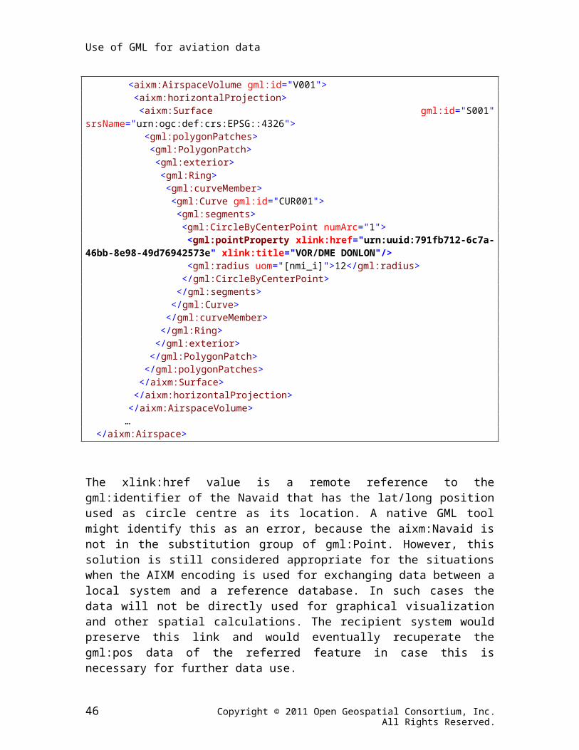
Use of GML for aviation data
GM_OffsetCurve Any Offset control points for Linestring calculated
LineString
GM_ArcStringByBulge Any Densified LineString
GM_Clothoid Any Densified LineString
GM_CubicSpline Any Densified LineString
GM_Knot Any Densified LineString
GM_BSpline Any Densified LineString
GM_Bezier Any Densified LineString
*Arcs and circles are interpreted as being the set of points at an equal distance from the centre point on the elipsoid. In non-geodetic coordinate systems this can result in shapes which are not circular in the projected coordinate system. OGC members can find more information on arc interpretation at
https://portal.opengeospatial.org/twiki/bin/view/SAAPilot/SaaPilotArcByCenterPointSummary.
** In a geodetic coordinate system a linestring and a geodesic between two control points follow the same path.
*** Some implementations of simple geometry are strict about arc interpolation and only allow circular arcs in projected planar coordinate systems. This is because, on an ellipsoid, points at an equal distance from a centre point do not form a circular arc.
Since both geometry models use a boundary value representation, the densification of curves can be applied to surface boundaries. No additional transformations are required for surface geometries.
10.2.3 Loss of data structure
The simple model contains less information than the ISO/GML model. ISO/GML geometries which have been mapped to simple geometry therefore cannot be reconstructed from their simple representation.
Where curves have been densified the original (and potentially more precise) representation is not preserved. The simplified geometry is therefore very useful for most practical purposes, but may not be sufficient close to the original for audit and accountability purposes i.e. it is not exactly the same geometry which was supplied in the GML.
48 Copyright © 2011 Open Geospatial Consortium, Inc. All Rights Reserved.

Use of GML for aviation data
Annex A - ArcByCenterPoint Interpretation Summary
Introduction
This annex contains the summary of the discussions on the correct interpretation of ArcByCenterPoint.
Angle Measuring Convention in GML
GML implements the semantics of ISO 19107. As such, the semantics for an angle encoded in GML is given by ISO 19107 clause 6.3.12.2: "In this variant of Bearing usually used for 2D coordinate systems, the first angle (azimuth) is measured from the first coordinate axis (usually north) in a counterclockwise fashion parallel to the reference surface tangent plane."
General Direction of Increasing and Decreasing Angle Values
ISO 19107 thus defines in which direction angle values increase and in which direction they decrease - see the following diagram:
Copyright © 2011 Open Geospatial Consortium, Inc. All Rights Reserved. 49

Use of GML for aviation data
Depending upon the "up" and the orientation of the first two axes, we have a left-handed or right handed coordinate system (see wikipedia and the following figure).
(Note: you can try this yourself with the following convention: thumb=x, index=y, middle=z)
Left-handed systems have a clockwise rotation from first to second axis (positive axis to positive axis). Right-handed systems have a counterclockwise rotation from first to second axis (positive axis to positive axis).
Note: the direction of "clockwise" and "counterclockwise" therefore depends on the "up", not the order of the first two axes in the coordinate system. Swapping the order of the first and second axis does not affect the direction of clockwise, just the direction of the rotation between the two axes.
In a left-handed system, angle values increase in clockwise direction. In a right-handed system, angle values increase in counterclockwise direction.
Note: The planes in geographic information are representations of the ground, and as such have a "natural" up direction (usually represented by a normal vector). In a 3D
50 Copyright © 2011 Open Geospatial Consortium, Inc. All Rights Reserved.
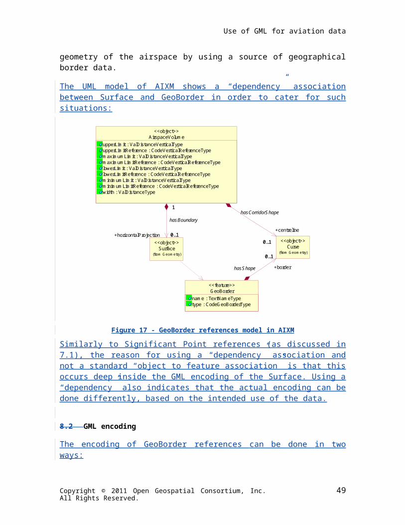
Use of GML for aviation data
system, "up" is given by the definition of the third axis in the chosen CRS. In a 2D system "up" is usually implied.
Angle Measurement in Different Coordinate Systems
Apparently the way that angle values are expressed heavily depends upon the axis order defined by the coordinate system that is used.
The following diagram shows how angles are measured in WGS 84 2D with different coordinate systems:
(A) GeodeticCRS: urn:ogc:def:crs:OGC:1.3:CRS84
Datum: WGS84
Ellipsoidal 2D CS.
o Axes: (1st) longitude, (2nd) latitude.
o Orientations: east, north. UoM: degree
(B) GeodeticCRS: urn:ogc:def:crs:EPSG::4326
Datum: WGS84
Ellipsoidal 2D CS.
o Axes: (1st) latitude, (2nd) longitude.
o Orientations: north, east. UoM: degree
The order of the axes determines where 0° is located.
Definition: The 0° angle is located on the positive part of the coordinate system's first axis.
Copyright © 2011 Open Geospatial Consortium, Inc. All Rights Reserved. 51

Use of GML for aviation data
Note: As explained in the previous section, the order of the first two axes and their location "on the ground" in combination with the "up" direction defines in which directions the angle values increase/decrease.
Direction of an Arc
The direction of a line is always from its start to its end. The same is true for arcs defined by a start and end angle.
Definition: if the start angle is smaller than the end angle then the arc direction is the direction in which the angle values increase.
Note: depending upon the coordinate system that applies to a given ArcByCenterPoint, this results in a clockwise (left-handed system) or counter-clockwise (right-handed system) directed arc.
Example A: CRS urn:ogc:def:crs:OGC:1.3:CRS84 has long/lat axis order. Because the orientation of the axes on the earth surface is the same as that of the first_axis (=x) / second_axis (=y) coordinate system assumed by ISO 19107, angle values increase in counter-clockwise direction in both cases. Thus, if the start angle of an ArcByCenterPoint in this CRS is smaller than its end angle, then the direction of the arc is counter-clockwise; otherwise it is clockwise.
Example B: CRS urn:ogc:def:crs:EPSG::4326 has lat/long axis order. Even though the axes have the same orientation on the earth surface as in example A, the axis order of the coordinate system is different! In the EPSG:4326 CRS, the "counter-clockwise" convention from ISO 19107 actually corresponds to a clockwise rotation, because the first_axis (=x) / second_axis (=y) coordinate system assumed by ISO 19107 is mirrored (reflected) through the x=y diagonal when transposing the coordinate system used by EPSG:4326 on the surface of the Earth. Because of this, if the start angle of an ArcByCenterPoint in EPSG:4326 is smaller than its end angle, then the direction of the arc on the earth surface is clockwise; otherwise it is counter-clockwise.
In other, more mathematical words: angle values increase in counter-clockwise direction if the coordinate system of the CRS used for an ArcByCenterPoint can be transformed into the coordinate system implied by ISO 19107 through a simple rotation. Whenever a reflection across the x=y line is needed (+ any rotation) to achieve the axis orientation of the given CRS's coordinate system then the angle values of an arc increase in clockwise direction.
Examples
The following diagrams exemplify this definition. They show the arc on a line representing a flattened circle first, followed by its representation in the general case.
Notes:
52 Copyright © 2011 Open Geospatial Consortium, Inc. All Rights Reserved.

Use of GML for aviation data
as angle values have an unlimited range, the flattened circle is a theoretically unlimited line.
each angle (from [0°,360°[) on the circle has an unlimited number of representations: angle + X * 360°, X being an integer
to define arcs on a circle, it is important that the difference between end and start angle is smaller than 360°: |end-angle - start-angle| < 360° (else the result would be an arc that is greater than or equal to 360° and looks like a circle)
computing the length of an arc can be performed as follows: |startAngle – endAngle|/180° * radius * pi - the definition conforms to this formula
The according ArcByCenterPoint would look like the following (with start and end angles as used in the examples):
<gml:ArcByCenterPoint numArc="1"
xsi:schemaLocation="http://www.opengis.net/gml/3.2 http://schemas.opengis.net/gml/3.2.1/gml.xsd"
xmlns:xsi="http://www.w3.org/2001/XMLSchema-instance"
xmlns:gml="http://www.opengis.net/gml/3.2">
<gml:pointProperty>
<gml:Point gml:id="ID1">
<gml:pos>0 0</gml:pos>
</gml:Point>
</gml:pointProperty>
<gml:radius uom="m">1</gml:radius>
<gml:startAngle uom="deg">actual_start_value</gml:startAngle>
<gml:endAngle uom="deg">actual_end_value</gml:endAngle>
</gml:ArcByCenterPoint>
Note that the spatial reference system - and thus the coordinate system - to be used cannot be directly defined in the ArcByCenterPoint. It is the same as that of the Curve that the ArcByCenterPoint is a segment of.
Copyright © 2011 Open Geospatial Consortium, Inc. All Rights Reserved. 53

Use of GML for aviation data
example - one
example - two
54 Copyright © 2011 Open Geospatial Consortium, Inc. All Rights Reserved.

Use of GML for aviation data
example - three
example - four
Copyright © 2011 Open Geospatial Consortium, Inc. All Rights Reserved. 55

Use of GML for aviation data
example - five
example - six
56 Copyright © 2011 Open Geospatial Consortium, Inc. All Rights Reserved.

Use of GML for aviation data
Copyright © 2011 Open Geospatial Consortium, Inc. All Rights Reserved. 57

Use of GML for aviation data
Annex B – GML change request – support arbitrary rhumblines
The following change request has been raised within OGC in order to enable specifying additional interpolations, such as rhumbline.Title: GML: Make CurveInterpolationType and SurfaceInterpolationType expandable
codelists.
Source:
Work item code: Date: 2008-11-11
Category: B
Use one of the following categories:F (Critical correction)A (corresponds to a correction in an earlier release)B (Addition of feature), C (Functional modification of feature)D (Editorial modification)
Detailed explanations of the above categories canbe found in the TC Policies and Procedures.
Reason for change: (1.) Other curve interpolation types needed in applications (e.g. rhumb lines in Aeronautical Information (AIXM), often used in (aerial and naval) navigation).(2.) ISO 19107 GM_CurveInterpolation and GM_SurfaceInterpolation are <<CodeList>>s that are expandable per definition.
Summary of change: Change the definition of CurveInterpolationType (10.4.7.3) and SurfaceInterpolationType (10.5.12.3) such that both become extendable codelists in either of the two ways specified in E.2.4.9 to allow the use of other values than the predefined ones. This also brings the implementation in line with ISO 19107, where both types are <<CodeList>>s, which are supposed to be implemented as expandable types.
58 Copyright © 2011 Open Geospatial Consortium, Inc. All Rights Reserved.

Use of GML for aviation data
Annex C – Considerations about interpolations
Role of interpolation
GML (in conformity with ISO:19107) establishes standards to specify the CRS of geographic points, in order to unambiguously identify their position on the Earth surface. Particular attention has to be paid to the definition and Earth location of extended geometric entities (curves and surfaces).
In GML, curve segments are defined by means of a set of control points and control parameters. They also have an enumerator attribute called “interpolation”, specifying the mechanism used to determine the exact geographic extent of the curve, out of the control points and parameters. Its possible values include “linear” and “geodesic”.
The notion of “linear” interpolation relies on the existence of a “vector” (or “linear”) structure on the surface. We are used to take it for granted that such a kind of structure exists. This is the case for a “flat” surface, isomorphic to , because is endowed with a natural linear structure. But this is not true in general, and in particular, it is not true for a curved surface, such as the Earth. So, in principle, it doesn’t make sense to talk about linear segments on the Earth! Actually we can bypass this conceptual problem by slightly changing the definition of linear interpolation. This can be done by relying on the choice of a local CRS3: a linear segment joining two given points, A and B, will be the locus of points whose coordinates belong to the convex linear combination the endpoint coordinates:
The drawback of this definition is that two different CRS on the same surface will give rise to two different “linear segments” (two different sets of points) joining the same couple of points.
Why geodesic is better
Things are a little bit different with the notion of “geodesic” interpolation. This is independent from the chosen CRS and just relies on the existence of a specific metric structure on the surface. So, contrary to linear ones, geodesic segments joining two given points on the Earth are well defined and independent from the choice of a projection (CRS). The same is true for any other kind of curve. For instance, a circumference (circular arc) of given center and radius, will have a fixed shape on any (projected) chart but will correspond to different curves on the Earth. On the contrary, a “geodesic arc”
3 a linear structure is locally implicitly defined by the coordinate system itself, namely by the local mapping of the surface on
Copyright © 2011 Open Geospatial Consortium, Inc. All Rights Reserved. 59

Use of GML for aviation data
(the locus of points equidistant, with respect to the ellipsoidal metric, from a given center) will have a different shapes in different charts, corresponding to the same set of points on the Earth.
The geodesic interpolation is a better choice than the linear one, for at least two further reasons:
1. many curves in aeronautical applications (e.g. the footprint of a GPS driven aircraft) are actually geodesic in nature rather than linear
2. worldwide aeronautical data originators adopt many different CRSs (the most convenient one for their own location). When putting together data coming from different originators (hence different CRSs), it is by far computationally easier, for a GIS system, to deal with geodesic entities on a given ellipsoid (such as WGS 84) rather than dealing with linear objects coming from different CRSs
Practical considerations
The purpose of the GML aeronautical profile should be ensuring that the geometric content of AIXM messages is unambiguously interpreted by any aeronautical application. A good mathematical definition is necessary but it is by no means sufficient in order to unambiguously exchange geographic information. If the applications exchanging data are not able to correctly deal with its geometric content, the effort of defining a rigorous language is almost vain.
One of the most critical issues is the accuracy with which geometric entities have to be stored and exchanged. The magnitude of the errors implicitly committed by erroneously interpreting the interpolation of an extended object may broadly vary, depending on many factors, such as the choice of CRS, the location of the object with respect to the CRS natural domain, the extension of the object itself, etc.. In many cases they are (almost) negligible for aeronautical purposes. But it is not rare to run into big troubles which can be brought back to the inaccuracy of the underlying computation engines of the applications dealing with geographic data.
Hardly any GIS application, nowadays, is actually able to correctly deal with geodesic entities. Apart for a few specific tools, GIS usually treat geodesic objects as linear in many respects (for computation and visualization purposes). One of the most used tricks to reduce approximation errors of extended objects is their “densification”. Densification has anyway its drawbacks:
the original geometric data (the extended curve) is altered, with integrity loss;
the subsampling introduces a given amount of arbitriness and irreversibility (from the subsampled geometry it is not possible recover the original data);
the approximated representation implies anyway some computational errors (consider, for instance the difference between a circular arc and a chord approximating the arc);
60 Copyright © 2011 Open Geospatial Consortium, Inc. All Rights Reserved.

Use of GML for aviation data
different applications may require different accuracy levels and hence a different amount of “densification”.
For all of these reasons, the GML aeronautical profile should look forward to the future and set down the foundations for a rigorous geographic information exchange among the next generation of aeronautical applications, leaving to each application the responsibility to manage the geometric content in the most proper way for its purposes.
Copyright © 2011 Open Geospatial Consortium, Inc. All Rights Reserved. 61

Use of GML for aviation data
Annex D – Offset Curve and Airspace Corridor encoding issues
Introduction
An offset curve is a curve at a constant distance from the basis curve. It is specified by providing:
a “baseCurve”, which is a reference to the curve from which this curve is defined as an offset;
a “distance”, which is the distance at which the offset curve is generated from the basis curve; in a 2D system, positive distances are to be left of the basis curve, and negative distances are right of the basis curve;
a “refDirection” (optional), which is used to define the vector direction of the offset curve from the basis curve. It shall not be used in AIXM/GML encodings, where all offset curve are used in 2D cases. In that case, distance defines left side (positive distance) or right side (negative distance) with respect to the tangent to the basis curve.
The first thing to be clarified about offset curves is how they are constructed in case the base curve is not a straight line. The correct interpretation is as shown in the diagram A below, because the offset needs to be perpendicular to the tangent of the base curve at every point. Diagram B is not a correct interpretation.
Figure 18 – Correct interpretation of offsetCurve
The second issue is constructing an offset curve when the base curve is composed of segments that sudden changes of direction. The most simple situation is when the base curve is composed of two consecutive straight lines. The tangent “jumps” at the
62 Copyright © 2011 Open Geospatial Consortium, Inc. All Rights Reserved.

Use of GML for aviation data
intersection of two segments, therefore creating either a gap or an intersection between the two offset segments, as shown in Figure .
To add figure here
In fact, the encoding of an airspace corridor requires the use of two gml:OffsetCurve elements and two gml:ArcByEdge, which connect the ends of the two offset curves, as shown in Figure 19. The points P1’, P2”, P1’’’ need to be calculated in order to define the closing arc, and similar for the points P2’, P2’’, P2’’’.
What we actually need is a “buffer” around the base curve. This does not seem to exist in GML.
Base curveP1'
P1"
P1
P2 P3
P4
P4'
P4"
P4’’’
P1’’’
Half-width
Offset curve #2
This is what we mean. It would be nice if OffsetCurve meant the same, but this is not sure. Explain why.
Copyright © 2011 Open Geospatial Consortium, Inc. All Rights Reserved. 63

Use of GML for aviation data
Base curveP1'
P1"
P1
P2 P3
P4
P4'
P4"
P4’’’
P1’’’
Half-width
Offset curve #1
Offset curve #2
Figure 19 - Airspace corridor encoding
64 Copyright © 2011 Open Geospatial Consortium, Inc. All Rights Reserved.