use of flumes in measuring discharge at gaging stations · use of flumes in measuring discharge at...
TRANSCRIPT
SURFACE WATER TECHNIQUES
Use of Flumes in
Measuring Discharge
at Gaging Stations
HYDRAULIC MEASUREMENT AND COMPUTATION
BOOK 1
CHAPTER 16
1965
UNITED STATES DEPARTMENT OF THE INTERIOR GEOLOGICAL SURVEY

SURFACE WATER TECHNIQUES
Use of Flumes in
Measuring Discharge
at Gaging Stations
Book 1 Hydraulic Measurement and Computation
Chapter 16 Use of Flumes in Measuring Discharge
at Gaging Stations

SURFACE WATER TECHNIQUES SERIES
Reports in this series that have been issued to date are listed below. An asterisk indicates the report has been published and is for sale by the Superintendent of Documents.
Book 1, Chapter 1, Computation of Water-Surf ace Profiles in Open Channels, 1964Book 1, Chapter 1, Supplement No. 1, Backwater at Bridges, 1964Book 1, Chapter 2, Computation of Discharge in Tidal Reaches, 1964Book 1, Chapter 8, Computation of Stage-Discharge Relationships at Culverts, 1965Book 1, Chapter 10, Stage Measurement at Gaging Stations, 1965Book 1, Chapter 11, Discharge Measurements at Gaging Stations, 1965Book 1, Chapter 12, Discharge Ratings at Gaging Stations, 1965Book 1, Chapter 14, Measurement of Discharge by Dye-Dilution Methods, 1965Book 1, Chapter 15, Computer Technique for Slope-Area Measurements, 1965Book 1, Chapter 16, Use of Flumes in Measuring Discharge at Gaging Stations, 1965
Book 2, Chapter 1, Storage Analyses for Water Supply, 1964
November 1965
11

PREFACE
The primary purpose of "Surface Water Techniques" is to provide members of the Surface Water Branch with information on technical procedures which will assist and guide them in planning and executing specialized work. The material is grouped under four main subject headings, designated as "Books, " as follows:
Book 1. Hydraulic measurement and computationBook 2. Hydrologic analysisBook 3. Instruments and equipmentBook 4. Design of investigations
Subject matter is grouped into books and chapters with the chapter being the unit of publication and also of revision. Techniques change from time to time, thus publication by chapters permits ready revision when appropriate. Instruc tions contained in the chapters as initially released are considered provisional and subject to revision because of experience in use or because of advancement in knowledge, techniques or equipment.
Judgment must be used in deciding how closely to adhere to instructions. Instructions which include information on preparation of data for use in a com puter must be closely followed. Instructions on methods of analysis are generally less binding and not to be utilized to the extent of inhibiting initiative or stifling progressive development. However, before using a technique which differs substantially from one which has been recommended, it should be dis cussed with the office of the Branch Chief.
When a technique has been sufficiently developed a new edition will be issued in similar format but in a more permanent form. Publication will be announced in "New publications of the Geological Survey" and the report will be for sale by the superintendent of Documents, but will have no automatic free distribution out side of the Survey.
111

CONTENTS
Page
Surface Water Techniques series. . . .Preface ..........................Abstract. .........................Introduction. ......................Principles governing the design of flumes ..........................
Type I, tranquil flow, small width reduction ......................
Type II, critical flow, large width reduction ......................
Type III, tranquil flow, small in crease in bed elevation. .........
Type IV, supercritical flow, width reduction, steep slope ..........
Type V, supercritical flow, width reduction, drop in bed ..........
Type VI, supercritical flow, steep slope..........................
The Parshall flume ................Development....................Flume configurations and dimen sions. .........................
Discharge ratings ...............
11iii
11
1
2
2
5
5
6
666
Page
The Parshall flume--Continued Use of Parshall flumes in natural
channels. ........................ 15Portable Parshall flumes. .......... 15
The San Dimas flume ................ 15Design and development............ 15Discharge ratings for original
design. .......................... 15Modified San Dimas flumes ......... 16
Type HS, H, and HL flumes .......... 16The trapezoidal flume. ............... 20
General design .................... 20Discharge relationships for one-foot
flume ........................... 20The three-foot trapezoidal flume .... 20
The construction and operation of flumes . ........................... 24Stage measurements ............... 24Discharge measurements in flumes. . 24 Winter operation .................. 25Construction features .............. 25
Summary and conclusions ............ 25References ......................... 27
ILLUSTRATIONS
Figure 1. 2.
10.11.12.
13.14.15.16.
17.
Specific energy diagram for rectangular channel. ............................Type I control, subcritical flow contraction obtained by small width reduction,horizontal bed ..........................................................
Type II control, critical flow contraction obtained by large width reduction,horizontal bed ..........................................................
Type III control, subcritical flow contraction obtained by small increase in bedelevation, horizontal bed.................................................
Type IV control, supercritical flow contraction obtained by width reduction andsloping bed .............................................................
Type V control, supercritical flow contraction obtained by width reduction anddrop in bed .............................................................
Type VI control, supercritical flow contraction obtained by steepening slope. . . .Configuration and descriptive nomenclature for Parshall flumes. ..............Discharge rating for "inch" Parshall flumes for both free-flow and submer
gence conditions ........................................................Correction factors for submerged flow through 1- to 50-ft Parshall flumes .....Modified 3-inch Parshall flume with rating for free-flow conditions. ...........Discharge ratings for different sizes of San Dimas flumes as originallydesigned ...............................................................
Discharge ratings for different sizes of modified San Dimas flumes. ...........Configuration and proportions of types HS, H, and HL flumes .................Configuration of the trapezoidal supercritical flow flume .....................Discharge rating curves and related data for one- and three-foot trapezoidalsupercritical flow flumes ................................................
Trapezoidal flume with infra-red heater and roof installation for winteroperation. ..............................................................
Page
3
4
4
5
7
7
23
26

CONTENTS
TABLES
Page
Table 1. Dimensions and capacities of all sizes of standard Parshall measuring flumes. . . 102. Discharge table for Parshall measuring flumes , sizes 1 foot to 50 feet for
free -flow conditions...................................................... 123. Discharge rating table for various sizes of HS, H, and HL flumes. ............. 21
vi

USE OF FLUMES IN MEASURING DISCHARGE AT GAGING STATIONS
By F. A. Kilpatrick
ABSTRACT
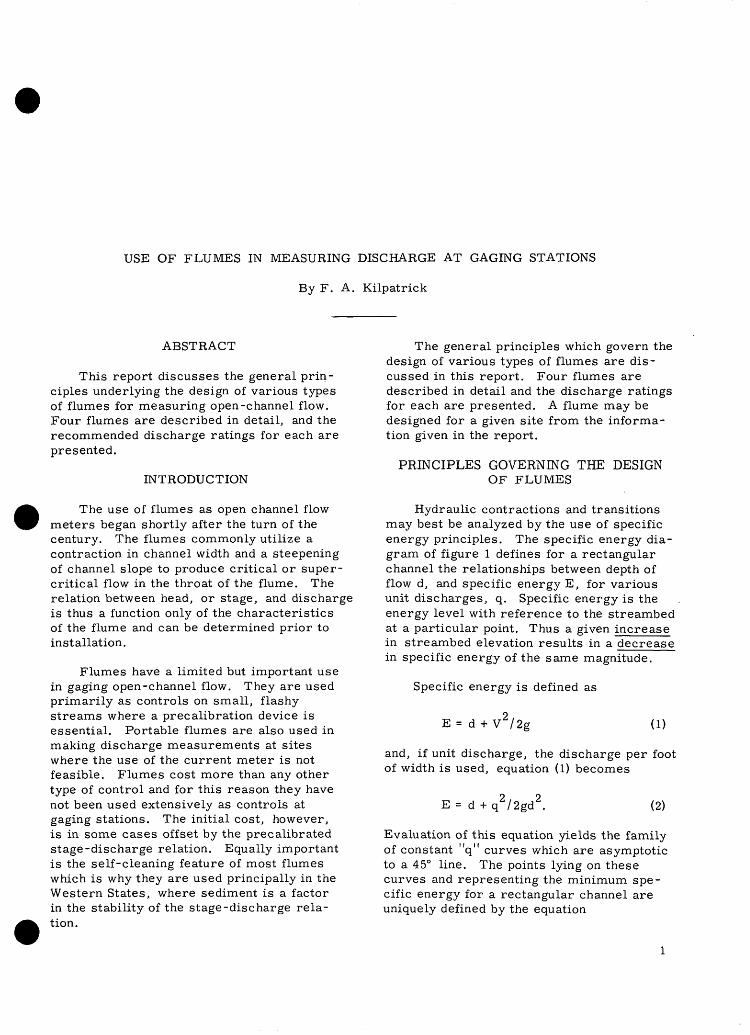
This report discusses the general prin ciples underlying the design of various types of flumes for measuring open-channel flow. Four flumes are described in detail, and the recommended discharge ratings for each are presented.
INTRODUCTION
The use of flumes as open channel flow meters began shortly after the turn of the century. The flumes commonly utilize a contraction in channel width and a steepening of channel slope to produce critical or super critical flow in the throat of the flume. The relation between head, or stage, and discharge is thus a function only of the characteristics of the flume and can be determined prior to installation.
Flumes have a limited but important use in gaging open-channel flow. They are used primarily as controls on small, flashy streams where a precalibration device is essential. Portable flumes are also used in making discharge measurements at sites where the use of the current meter is not feasible. Flumes cost more than any other type of control and for this reason they have not been used extensively as controls at gaging stations. The initial cost, however, is in some cases offset by the precalibrated stage-discharge relation. Equally important is the self-cleaning feature of most flumes which is why they are used principally in the Western States, where sediment is a factor in the stability of the stage-discharge rela tion.
The general principles which govern the design of various types of flumes are dis cussed in this report. Four flumes are described in detail and the discharge ratings for each are presented. A flume may be designed for a given site from the informa tion given in the report.
PRINCIPLES GOVERNING THE DESIGN OF FLUMES
Hydraulic contractions and transitions may best be analyzed by the use of specific energy principles. The specific energy dia gram of figure 1 defines for a rectangular channel the relationships between depth of flow d, and specific energy E, for various unit discharges, q. Specific energy is the energy level with reference to the streambed at a particular point. Thus a given increase in streambed elevation results in a decrease in specific energy of the same magnitude.
Specific energy is defined as
E = d + V /2g (1)
and, if unit discharge, the discharge per foot of width is used, equation (1) becomes
E = d+q2 /2gd 2 . (2)
Evaluation of this equation yields the family of constant "q" curves which are asymptotic to a 45° line. The points lying on these curves and representing the minimum spe cific energy for a rectangular channel are uniquely defined by the equation

USE OF FLUMES IN MEASURING DISCHARGE AT GAGING STATIONS
(3)
This equation defines the line of critical depths as shown in figure 1. At this critical depth, there is the unique relationship in which the velocity head is exactly half the depth of flow. Flow conditions more com monly found in rivers and streams are tran quil or subcritical and are represented by the curves above the line of critical depth. In this region depths are large, and veloci ties and velocity heads are relatively small. Conversely, in the supercritical flow region below the critical-depth line, depths are small, and velocities and velocity heads quite large.
Six methods employed in various flume designs, as illustrated in figures 2 7, will be discussed using the specific energy dia gram of figure 1. Application of specific energy principles to abrupt contractions and short channels is not entirely correct due to accelerative and curvilinear flows. However it is the concept that is of interest here and not an exact analysis.
Type I, Tranquil Flow, Small Width Reduction
The earliest measuring or rating flumes are exemplified by figure 2 which shows sub- critical flow entering a flume with side con tradictions. The side contractions reduce the width of the flume which results in an increase in unit discharge.
Because there is no change in bed ele vation, and minor energy loss, the specific energy in the throat is about the same as in the approach. With constant specific energy, the effect of a small width contraction is a lowering of the water surface in the throat. In the example shown in figure 2, the side contraction between point A and point B causes a change in the discharge per unit width. The transition is illustrated in figure 1, as the point A on the curve q = 1, and the point B on the curve q = 2. Owing to the small degree of contraction, critical depth is not accomplished (point C on curve q =3, in figure 1). It is necessary in this type of flume to measure the head in both the ap proach section and in the throat. For this reason, a subcritical flow meter of this type is seldom used today.
Type II, Critical Flow, Large Width Reduction
Further narrowing of the throat width, as before, results in increasing the unit discharge until a critical width is reached. (See figure 3.) This width corresponds to point "C" on figure 1 and represents the minimum specific energy which exists at the critical-flow depth. Earlier flume designs were based on measuring this depth in the throat because of the unique critical-depth: discharge relationship of equation 3.
The discharge equations for flumes con form closely to this relationship, but it can be seen that depths in the vicinity of critical flow can change radically with little change in discharge. Thus, flow close to critical is very unstable, constantly attempting to become either subcritical of supercritical.
In both type I and type II controls, the flume slope may be zero or nearly zero owing to the relatively small energy losses experienced.
In a type II control, stage may be meas ured at either of two locations, in the imme diate approach to the flume or in the throat. Measurement in the approach will yield a more sensitive stage-discharge relationship because changes in discharge will result in greater changes in depth in subcritical flow than would like changes in discharges in critical flow. Unfortunately, the stage- discharge relationship in the approach may be unstable owing to approach conditions such as scour and fill. Consequently, stage is usually measured in the throat to alleviate influence from either upstream or down stream. Approach conditions can have some influence on flow in the throat, but it is generally insignificant. The location at which critical depth is first reached may shift further downstream into the throat as a result of excessive deposition in the approach. For this reason, and to avoid possible flow separations near the entrance, stage meas urements in the throat should not be too close to the entrance.
A type II control, properly called a critical-depth meter, has the advantage of requiring measurement at only one location. It has the disadvantage that free overfall is required for best operation. Measurement upstream is not entirely satisfactory because

PR
INC
IPL
ES
G
OV
ER
NIN
G
TH
E
DE
SIG
N
OF
F
LU
ME
S
i gofl cd -*-> o a;W
) rt
CO
c\

USE OF FLUMES IN MEASURING DISCHARGE AT GAGING STATIONS
Q=30cfs
DUAL GAGING POINTS
A »-B
1d=0.98 E -i ~T i
d c =0.3l j * 1
^*\^ ̂ i
='.o _ d:9-
dc =0.50
j
i
93
E
_x^g" 1
d ~N
= 1.0 '
^ w.s.
0.98
. U. L
Figure 2. --Type I control, subcritical flow contraction obtained by small width reduction, horizontal bed.
0 =30cfs
ALTERNATE GAGING POINTS
de sQ.C.D.L.
Figure 3. --Type II control, critical flow contraction obtained by large width reduction, horizontal bed.

PRINCIPLES GOVERNING THE DESIGN OF FLUMES
of possible approach influences, nor is it satisfactory in the throat because of widely fluctuating water surfaces. As will be shown subsequently, much is to be gained by placing such a flume on a slope greater than critical.
Type III, Tranquil Flow, Small Increase in Bed Elevation
Types I and II controls represented methods of obtaining measuring flumes by contracting the flow using width reductions. In these cases, as can be seen on the specific energy diagram in figure 1, the specific energy, E_, is essentially constant from ap proach to throat. All changes in depths from approach to the throat are accomplished by going to successively larger c[ curves.
Flow conditions similar to those pro duced by the side contractions, as in types I and II, can be obtained by increasing the bed elevation. In the absence of side con tractions, the unit discharges will not vary from approach to throat, but the specific energy, E_, will change.
For a type III control with E_ = 1. 0 in the approach and c[ = 1. 0 throughout, the change in depth must be along a constant c[ curve. AS illustrated in figure 4, this can only be effected by a reduction in specific energy. Hence, if the bed of the flume is arbitrarily raised 0. 25 feet above the approach bed, the result is a direct reduction in E_ to 0. 75 feet over the sill or to point "D" on figure 1.
This yields a depth of approximately 0. 72 feet, which is still subcritical. Because £ is the same in both approach and over thesill, d is 0. 31 feet in both cases,
c
Raising the bed even further produces lower and lower depths across the sill until critical depth is reached at point "E" on fig ure 1. At this point where the specific en ergy is a minimum, E_ = 0.47 feet. Hence, a sill height of 0. 53 feet is the critical height because a sill of greater height will produce increased stages upstream. A critical depth of 0. 31 feet will exist at the sill.
Flumes which incorporate sills in their design are the least frequently used. Among the primary advantages of flumes as discharge meters are their self-cleaning characteris tics. As might.be expected, sills form a partial barrier to the approaching flow, which encourages deposition. Therefore, there would appear to be no advantage to flume designs incorporating sills or raised floors.
Type IV,-Supercritical Flow, Width Reduction, Steep Slope
When flumes are on approximately zero slope, as in types I, II, and III, critical depth is the minimum depth possible in the flume. When the flow in the throat reaches the critical discharge a critical contraction has been reached. Further contraction from the sides or the bottom or both will not pro duce supercritical flow.
q = LO d=0.98ri
»- D
E=I.O
.E.L. -=- W.S.
E=0.75q=I.O
d r =0.3l
'dc =.3l d =0.72
[DUAL GAGING POINTS
C.D.L.
Figure 4. --Type III control, subcritical flow contractionobtained by small increase in bed elevation, horizontal bed.

USE OF FLUMES IN MEASURING DISCHARGE AT GAGING STATIONS
The design of a flume with supercritical flow in the throat can be accomplished only by increasing the available specific energy from the approach into the throat. Whereas a rise in the flume bed decreased the spe cific energy, a drop in the flume bed or an increase in flume slope serves to increase the specific energy. Type IV control in figure 5, therefore, is identical with type II, but has been placed on a slope to supply the required increase in specific energy to produce supercritical flow in the throat.
Type V, Supercritical Flow, Width Reduction, Drop in Bed
Supercritical flow is obtained abruptly by dropping the bed as in type V (see figure 6). Thus, for a particular discharge the path "A-B-C-F" in figure 1 is followed; A, representing flow in the approach; A to C the effect of the side contraction or movement from one c^-curve to successively higher ones; and C to F occurring because of increased specific energy provided by the slope or drop but no further contraction.
Properly, such flumes should be called supercritical-flow meters. As in the criti cal-flow meters, measurement of head is made either in the throat or the approach. The advantages and disadvantages of meas uring in the approach have already been dis cussed. As previously emphasized, meas urement of head in critical flow as at point "C", is undesirable since there maybe large fluctuations in depth with little or no change in discharge. Therefore, head is custom arily measured downstream of the point of critical depth in the region of supercritical flow. Measurement of head here may be difficult owing to the high velocities en countered under such conditions. As can be seen in figure 1, a particular disadvantage of measuring depths in this region is the lack of rating sensitivity compared with measure ments in subcritical flow. The primary ad vantage of a supercritical-flow flume is that it has optimum self-cleaning and scouring characteristics. A discharge rating based on stage measurements in the region of supercritical flow is the least influenced by disturbances either upstream or downstream, and hence is apt to be the most stable. By the same token, such flumes are the most capable of stable operation up to high sub mergences.
Type VI, Supercritical Flow, Steep Slope
It should not be construed that contrac tion and increase in specific energy are both necessary for supercritical flow to occur. A sufficient increase in specific energy alone can produce supercritical flow. In the case of the ordinary stream-gaging control this is obtained simply by the drop created by the physical presence of the control.
As can be seen in figure 7, flow at supercritical depths can also be produced over a broad crest simply by giving it suf ficient downstream slope.
A slope of 1 degree is usually sufficient to produce critical depth in the vicinity of the upstream edge of the apron, but waves and disturbances are apt to be numerous downstream. Such wave disturbances occur when flow across the apron is too close to critical and not well within the supercritical- flow range. On ordinary concrete aprons, slopes from 2^% to 5% have been found to yield depths well within the supercritical- flow range.
For type VI control, if approach con ditions were not subject to change, a stable discharge rating could be expected to exist by measuring stages in the subcritical region upstream. If accurate stage meas urements could be made in the region of supercritical flow down on the sloping crest, a stable discharge rating would be obtained regardless of upstream or downstream dis turbances. However, such a rating would be very insensitive. The addition of side con tractions improves the rating sensitivity. Thus, the ideal flume is basically a broad- crested weir, flat or sloping, with side con tractions.
THE PARSHALL FLUME
Development
The development of measuring flumes was instigated largely by the need for meas uring irrigation flows. Prior to 1920 most flumes were similar to types I, II, III. The Venturi flume developed by V. M. Cone (1917), was the forerunner of the Par shall flume. It was similar to types I and II and required the measurement of stage both upstream and in the throat of the flume.

THE PARSHALL FLUME
q=l,0 q=3.0
^ALTERNATE; GAGING POINTS
C.D.L.
Figure 5. --Type IV control, supercritical flow contraction obtained by width reduction and sloping bed.
DUAL GAGING POINTS
A *-f
E.L.
-W.S.
-C.D.L.
Figure 6. --Type V control, supercritical flow contraction obtained by width reduction and drop in bed.

USE OF FLUMES IN MEASURING DISCHARGE AT GAGING STATIONS
s.'Q ° '/////////,
JUMP -- C.D.L.
Figure 7. --Type VI control, supercritical flow contraction obtained by steepening slope.
In effect, the flume operated partially sub merged much of the time.
R. L. Parshall (1926) proposed changes in the design of the Venturi flume, the most essential of which was a drop in the floor. As depicted in figure 6, this drop supplied the necessary additional specific energy to produce supercritical flow through the throat.
The throat width of the earlier flumes ranged in size from 3 inches to 8 feet. Flumes with throat widths of 10 feet to 50
feet were later constructed and field cali brated. More recently Parshall flumes of 1- and 2-inch sizes were calibrated by Robinson (1957). Head-discharge ratings are thus available for a large range in throat width.
Flume Configurations and Dimensions
Figure 8 shows the configuration of the Parshall flumes and table 1 gives the dimen sions of all sizes. Flumes with throat widths from 3 inches to 8 feet contain a rounded
-Note: Three-inch to eight-foot flumes have rounded approach wingwalls
GageHead, HA
pointPLAN VIEW
SIDE VIEW
Figure 8. --Configuration and descriptive nomenclature for Parshall flumes.

THE PARSHALL FLUME
entrance with the entrance floor on a slope of 25 percent.
The smaller and larger flumes do not have this feature, and it is doubtful whether any of the flumes would be materially af fected by its absence as long as approach conditions are not unusual. Parshall flumes have provision for stage measurements both in the approach and in the throat, but the downstream gage is required only when sub merged-flow conditions exist. The datum for both gages is the level floor in the approach. The raised floor, length G, in the down stream diverging sections is designed to re duce scour downstream and to produce more consistent discharge relationships under con ditions of submergence. The percent sub mergence for Parshall flumes is defined as
with both stages referenced to common datum. Where free-fall conditions exist for all flows, the downstream gage, H may be
omitted and the entire diverging section left off if desired. This simplification has been used in the design of small portable Parshall measuring flumes.
Discharge Ratings
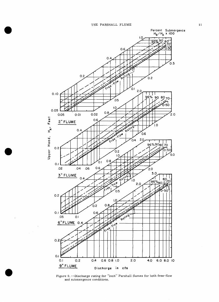
Figure 9 contains the discharge rating curves for the 2-inch through 9-inch size Parshall flumes both for free flow and for different degrees of submergence.
Table 2 gives the free-flow discharge ratings for flumes 1 to 50 feet in size. Cor rection factors for computing the effect of submergence for these sizes are given in figure 10. The discharge under submerged conditions is equal to the free-fall discharge minus the product of two correction factors,Q and k . Thus,
c s
Qf - ksQc
As can be seen in figures 9 and iO, greater submergences can be tolerated with in creased flume size.
The Parshall flume was developed for use in irrigation systems and was designed to
operate with the minimum of head loss. Un fortunately, many of the flumes are placed to operate much of the time under conditions of submergence. Experience has shown the desirability of determining the discharge rating for each flume, by current-meter measurements, especially under conditions of submerged flow. Often flumes are set so low that an unstable submerged-flow dis charge rating will exist because of ever- changing downstream backwater conditions. As a rule though, the Parshall flume has proven to be a satisfactory measuring device and yields entirely adequate results in meas uring water for irrigation.
The original design of Parshall flumes has been maintained through the years for widths ranging from 1 inch to 50 feet. The rating results heretofore have been expres sed in empirical form, either as tables or as equations. Davis (1963) has applied dimen sional methods to these data to develop a semi-theoretical equation relating flow and depth for all sizes from 1 inch to 50 feet for unsubmerged flow. His equation, for flumes
with side angles 9 = tan 0. 2, and dropdown
angles $ = tan 0.375, is
2YQ (1+0. « )2= 1.351 Q Q 0. 645
in which
Y = nondimensional depth, y /b
Q = nondimensional discharge,Q/g1/2 b 5/2
X = nondimensional distance, x/b
y = depth at measuring section
b = channel width at throat
Q = discharge
g = acceleration of gravity
x = distance from throat crest to measuring section.
Although the equation is somewhat cum bersome, the excellent agreement between it and all published data should be useful in permitting the use of nonstandard sizes of Parshall flumes. It could also be used to

10U
SE
O
F
FL
UM
ES
IN
M
EA
SU
RIN
G
DIS
CH
AR
GE
A
T
GA
GIN
G
ST
AT
ION
S
>
mo
oo
o
-HC
O <
^C3
coin
-stHin
o to
-j to
rt °°"
Co c«-(
.....
CO
Tt* CO
O
f^
in
CO
»-H
O5
O
O
O
O
O
O
O
O
GO
~
i CO
CO
--------
F~
t
CO0)
O
£
<2i o i
co in 05
iinrM
-nooooo
y ooooo
^-*
-*co
co
co
co
oin
_,
_ ^
.(Xj
(SI
r\j -co in
(->X
">£ 'c- «w3-1
co fM
co
r- r-
1
° ° °
J<«-<CJOC
I)
. »
'S
^O-!H
cd to
03 <
f\j
co co
or-coi^
ocor~
T
3<
UO
) -y
I--O5O
CO
O5
O-H
CO
CO
OC
OC
OO
CO
OC
DC
OC
OO
CO
OC
O
rt -
^
h
, Q
_
__
^^^^^
_ o
icoco
coca
om
oooo
Oh
n^iif^y)
HC
Oin
roO
O
rtl v
p.
w
^^.^
rgiv
j in
in
CO
r- -.
~^ (\J
ro O(05
SS
^°S
^cu
-- ________
** sL
^
3
<U O
OO
IMM
rv
jr\af\jr\jrv
l(\j(Mr\](N
]inunt^
OO
OO
OW
O.
""
o ____________
"* ft
+ Id
Tfrto
oin
m
ort
o ^^o^^,
t, «.
.9-5
(
O -S
. g>
g m
S§
cu
+j
i^-Q
fvjo
in
oo
oo
oo
oo
oo
oo
oo
oo
o
-^ >",-,
m m
o
3 3 >
"
I o
o- -
- W
3
O
'Sn
o
t^co
ooo
( 4 -'
rn"^
CO
OO
OO
in
OO
OO
OO
OO
OO
OO
OO
OO
O
^
£0
-H
N
-,
w c
- -
o
m o
tf in
r^ o o o
IMcom
OO
O
OO
OO
OO
OO
OO
OO
OO
OO
&
;~
^
°
^^
«M
NN
NN
NM
NM
««
*»
««
«0
«
'tV-d PQ0)
01>
Hg
m co
_ oin
oooooooococoO
cocococo
Q_ "
c)H
O5
O
CJ5 CO
a "S
<u .<u
o
< -H
rqcocom
cor-c
oro
^-iin
coin
oin
ooo
o o
o o
o o
o
CU
Q
+
J
fc,^
fH
-.
* '
c
~" J "' "' "~ ~"
tUOp oo'O
QJ
<<-i a)
a; "£
o
> .CO
T3
J3 to
.<u
at tsi
o"H
O
to £
CD ^
J3 *
O
.,
.s -s« fito
^0
CO NS .23
-ar
1 co
M
.
o <J
M
aJ o Z
THE PARSHALL FLUME 11
Percent Submergence H D /HA x 100
0.2
0.10
0.05
' I I96%9080 70
" " "0-50
O.IO.I 0.2
9"FLUME
0.4 0.6 0.8 1.0 2.0
Discharge in cfs
4.0 6.0 8.0 10
Figure 9. --Discharge rating for "inch" Par shall flumes for both free-flow and submergence conditions.
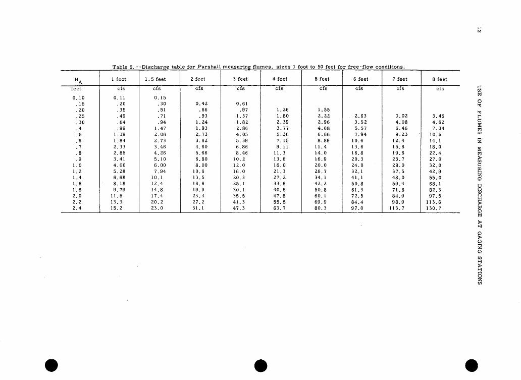
Table 2. --Discharge table for Parshall measuring flumes, sizes 1 foot to 50 feet for free-flow conditions.
HA
feet
0. 10.15.20.25.30.4.5.6.7.8.9
1.01.21.41.61.82.02.22.4
1 foot
cfs
0. 11.20.35.49.64.99
1.391.842.332.853.414.005.286.688.189.79
11.513.315.2
1 . 5 feet
cfs
0. 15.30.51.71.94
1.472.062.733.464.265.106.007.94
10.112.414.817.420.223.0
2 feet
cfs
0.42.66.93
1.241.932.733.624.605.666.808.00
10.613.516.619.923.427.231.1
3 feet
cfs
0.61.97
1.371.822.864.055.396.868.46
10.212.016.020.325.130. 135.541.347.3
4 feet
cfs
1.261.802.393.775.367. 159.11
11.313.616.021.327.233.640.547.855.563.7
5 feet
cfs
1.552.222.964.686.668.89
11.414.016.920.026.734.142.250.860.169.980.3
6 feet
cfs
2.633.525.577.94
10.613.616.820.324.032.141.150.861.372.584.497.0
7 feet
cfs
3.024.086.469.23
12.415.819.623.728.037.548.059.471.884.998.9
113.7
8 feet
cfs
3.464.627.34
10.514.118.022.427.032.042.955.068.182.397.5
113.6130.7

HA
feet
0.300.40.50.60.70.80.91.01.21.41.61.82.02.22.42.63.03.54.04.55.05.56.0
10 feet
cfs
5.759.05
13.017.422.227.533.339.452.767.483.5
100.9119.4139.0159.9181.7228.4294363437517
12 feet
cfs
6.7510.8515.420.626.232.739.446.862.680.199.1
119.8141.8165.0189.8215.7271.2347430518614
15 feet
cfs
8.413.319.125.532.740.448.957.977.399.0
122.8148,0175.3204235267335429531641759885
1016
20 feet
cfs
11.117.725.133.743.153.464.376.3
102.0130.5162195232269310352442566700846
100211661340
25 feet
cfs
13.821.831.241.853.466.380. 194.8
127.0162201243287334384437549703870
1051124414481664
30 feet
cfs
16.526. 137.250.064.079.295.5
113.2152194240290343400459522656840
10401255148617301988
40 feet
cfs
21.834.649.566.284.8
105127150201257318384454530609692870
111313791664197022952638
50 feet
cfs
27.343.261.882.6
105 . 5131158187250320396479567660758864
1084138717172073245328603285
Note: Available data indicates that extension of the above ratings to greater heads is reliable.

14 USE OF FLUMES IN MEASURING DISCHARGE AT GAGING STATIONS
0.3.06 .08 .10 .14 .18.2 a. FLUMES I - 8 ft.
.3 A .6 .8 1.0 1.4 2.0
DISCHARGE CORRECTION, Q c
8 10
cf s
6.0
a <LU
trUJCL a.
.5 .6 .8 1.0 2 468 10 20 40 60 80 100 200
DISCHARGE CORRECTION, Q C , cfs
b. FLUMES 10- 50 ft.
400
Figure 10. --Correction factors for submerged flow through 1- to 50-ft Parshall flumes.

THE SAN DIMAS FLUME 15
correct calibration curves of standard-size flumes that do not conform with the specified dimensions of throat width or upstream meas uring distance.
Using the same data on which Davis ' equation above is based, Dodge (1963) pro posed the following equation:
which gives reliable results for flumes with throat widths up to 6 feet.
Continued studies such as these should someday help to unify all Parshall flume data for submerged flows, and for other side angles and dropdown angles.
Use of Parshall Flumes in Natural Channels
The Parshall flume has been used in natural stream channels with varying degrees of success. Generally it will operate satis factorily in channels where the sediment dis charge is not too great or does not contain large rocks and other debris. Its use on flashy, cobble -strewn streams has been relatively unsuccessful. Because of the vertical-wall design, a given flume has a relatively small discharge capacity. While this is no handicap in irrigation systems, it may be on natural streams. Its lack of sensitivity at low flows is frequently over come by placing temporary weirs in the throat. At some gaging stations small Parshall flumes have been combined with other types of weirs or controls. Installa tions of this type are generally unsatifactory because the upstream stage is measured upstream from the flume and thus the rating is influenced by sediment deposits in the ap- aproach. A simple depressed "V" section in the weir control will prove just as adequate and less expensive.
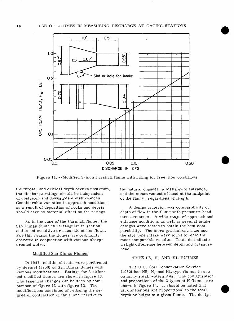
Portable Parshall Flumes
Figure 11 shows a portable modified Parshall flume, designed by C. A. Taylor and H. C. Troxell (1931), which has the diverging section removed. The flume is used only under free -flow conditions. The rating shown represents a slightly greater flow for a given head than that for the standard 3 -inch Parshall flume.
THE SAN DIMAS FLUME
Design and Development
As previously noted the Parshall flume while satisfactory for measuring irrigation flows, is generally not suited for measure ment of debris -laden flows. A flume for measuring such flows was developed in southern California at the San Dimas Experi mental Forest (1938). This flume is a super critical-flow flume rather than a critical- depth flume, as titled by the designers, be cause head measurements are made in the throat below the point where critical depth occurs. To produce supercritical flow, the floor of the flume was set on a 3° slope. The San Dimas flume as originally designed was rectangular in section with the config uration and dimensional relationships shown in figure 12. The stage gaging point was placed 3 feet below the entrance regardless of the size of the flume. This was in recog nition of the fact that the flume amounted to a broad-crested weir with side contractions.
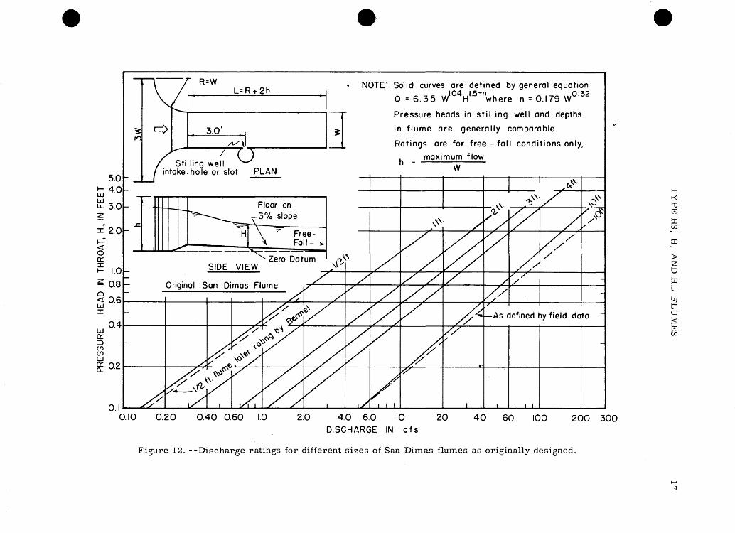
Discharge Ratings for Original Design
Figure 12 shows the discharge ratings for the different size flumes. The ratings for the 1-, 2- and 3-foot flumes were deter mined from tests on structures of this size. From this data a general equation
was developed where W is the throat width in feet, H the pressure head in the throat in
0 32feet; and n = 0. 179W ' . This general expression was found to apply to flume sizes 1 through 4 foot, but discharge measurements on a 10 -foot flume differed from the general expression as shown in figure 12. This was also true of a |-foot flume tested later. The differences probably result from the fixed location of the gaging point but variable total length of the flume. For the 10 -foot flume it is quite possible that for higher flows, the head was measured in the region of curvi linear flow near the free over fall or that parallel flow in the throat was not realized.
The San Dimas flume is capable of meas uring flows containing considerable sediment, rock and other debris. Because head meas urements are made in supercritical flow in
16
UJ UJu_
u
UJcc
1.0
0.5
O.I
0.05 0
" 0
-
~ "inN-" b
-
1.0' . 0.5'
^-^
c> . 0.67
-^
^^"inCVJb <r
^ *"~~~-~Slot or hole for intake
i ii 1
4i
X
// ,
XX^
.01
x
- -^
JX
XX
6
XX
X* LX
1
X
/
/
,
^X'
,
1
XIX
0.05 0.10 0.50DISCHARGE IN CFS
Figure 11. --Modified 3-inch Parshall flume with rating for free-flow conditions.
the throat, and critical depth occurs upstream, the discharge ratings should be independent of upstream and downstream disturbances. Considerable variation in approach conditions as a result of deposition of rocks and debris should have no material effect on the ratings.
As in the case of the Parshall flume, the San Dimas flume is rectangular in section and is not sensitive or accurate at low flows. For this reason the flumes are ordinarily operated in conjunction with various sharp- crested weirs.
Modified San Dimas Flumes
In 1947, additional tests were performed by Bermel (1950) on San Dimas flumes with various modifications. Ratings for 3 differ ent modified flumes are shown in figure 13. The essential changes can be seen by com parison of figure 13 with figure 12. The modifications consisted of reducing the de gree of contraction of the flume relative to
the natural channel, a less abrupt entrance, and the measurement of head at the midpoint of the flume, regardless of length.
A design criterion was comparability of depth of flow in the flume with pressure-head measurements. A wide range of approach and entrance conditions as well as several intake designs were tested to obtain the best com parability. The more gradual entrance and the slot-type intake were found to yield the most comparable results. Tests do indicate a slight difference between depth and pressure head.
TYPE HS, H, AND HL FLUMES
The U.S. Soil Conservation Service (1962) has HS, H, and HL type flumes in use on many small watersheds. The configuration and proportions of the 3 types of H flumes are shown in figure 14. It should be noted that all dimensions are proportional to the total depth or height of a given flume. The design
5.0
3.0
o or^ 1.0
^ 0.8
< 0.6UJX
UJa:^CD
I
0.4
0.2
O.I
(O
/fc^
n-w L=R-»-2h
3.0' , ,
/^»
NOTE: Solid curves are defined by general equation.
Q = 6.35 W1 H 15 "where n = 0.179 W° 32
Pressure heads in stilling well and depths
in flume are generally comparable
Ratings are for free-fall conditions only,
maximum flow
0.10 0.20 0.40 0.60 1.0 2.0 4.0 6.0 10 20 40 60 100 200 300 DISCHARGE IN cfs
HK}
^H
ffi
> 2 dffir*i r d§H en
Figure 12. --Discharge ratings for different sizes of San Dimas flumes as originally designed.

18 USE OF FLUMES IN MEASURING DISCHARGE AT GAGING STATIONS
1-LJ
t 6.0
z ~ 4.0X
g 2.0Xi-
Q 1.0
2 0.8X
0.6LJor => 0.4
UJccQ.
0.2
O.I
CM
-
" =
-
-
*!/*V/
^>
/ -
L
L/2
PLAN
=^ ./Level '
SIDE
V
VIEW
Modified San Dimas .
. Flume /
/^^
/7*
)/̂Stilling well i hole or slot
Floor on 3% Slope
1Zero cjatum '
/
/,r . ^~
l\f e a c s9
ntake
/V ///
lodifications are as suggested by Bermel xcept for total flume lengths which
re shorter. Ratings are for freefall ondition only. Pressure heads in tilling well and depth in flume are enerally comparable
/^'/
'
*v^/
^
^-$*' '
-
-
-
0.4 0.6 1.0 2.0 4.0 6.0 10 20 40 60 100 200 400
DISCHARGE IN cfs
Figure 13. --Discharge ratings for different sizes of modified San Dimas flumes.

I.05D
SIDE SHEET
,0.3830 , 0
1.050 1.50
FRONT ELEV SIDE ELEV.
HS FLUME
I.9D
GAGE
SIDE SHEET'
I.ID
1.90
O.3DI
I.35D
FRONT ELEV. SIDE ELEV.
H FLUME
3.20
SIDE SHEET 1
2.2D 0.50
>\7T^
I I/0.25D
1.50
FRONT ELEV. SIDE ELEV.
HL FLUME
M
ffi co
a
2! d
ffir
r dwen
Figure 14. --Configuration and proportions of types HS, H, and HL flumes.

20 USE OF FLUMES IN MEASURING DISCHARGE AT GAGING STATIONS
attempts to combine the sensitivity and ac curacy of the sharp-crested weir and the self-cleaning features of the flume. The result is a compromise of both. This flume is recommended for small streams where sediment would be a problem if the conven tional sharp-crested weir were used, but not where movement of coarse sediment and debris occurs on a large scale.
The H flumes do not exactly fit any of the flume examples shown in figures 2 7 and are in fact more weir than flume. Stage is meas ured upstream in subcritical flow and critical depth occurs over the crest as with any weir. If sediment accumulates in the approach, the discharge rating will be unstable. The design of the H flumes does decrease to some extent the accumulation of sediment.
Head is measured on the converging ap proach wall in a zone of accelerated flow. While this design feature is perhaps undesir able, it is probably better than measuring further upstream where approach conditions more seriously influence the rating. The converging walls are also conducive to self cleaning.
Table 3 gives the discharge ratings for the various types and size of flumes. These flumes are intended to operate under free flow conditions although submergences up to 50% have no significant effect on the ratings.
Where the H flumes can be used, they probably have an advantage over the other flumes discussed in simplicity of design and construction. The 3 plain surfaces composing the flume are ordinarily made of metal plate and can be prefabricated for assembly in the field. The flumes are usually mounted or cast into a concrete headwall. In many in stances lightweight sheet piling could be quickly driven to form both headwall and cut off for these flumes.
THE TRAPEZOIDAL FLUME
General Design
Both the Parshall and San Dimas type flumes have narrow ranges of discharge be cause of their vertical walls and are unsuited to the accurate measurement of low dis charges. The obvious solution to this prob lem was the sloping of the flume walls to pro duce a flume of trapezoidal shape.
The most promising design of a trapezoi dal flume and the one recommended here, was developed by A. R. Chamberlain (1957) and A. R. Robinson (1959). The configuration of the flume and dimensions for 1-foot and 3-foot flumes are shown in figure 15. This flume is of type IV shown in figure 5 but with sloping walls and measurement of stage (piezometric head) only in the super critical- flow section. This flume features walls at 30° slope with the horizontal; a flume-floor slope of 5% to produce supercritical flow; and 3 sections, an approach section, a converging section and a throat or supercritical-flow section. With a 1-foot throat the flume has a range in flow of from 1 to 350 cfs. The addition of a removable 120° V-notch weir to the throat exit is suggested for low flows. The discharge capacity of the flume can be increased by extending the walls where chan nel conditions permit, or by increasing the throat width.
Discharge Relationships for One-Foot Flume
This flume has been extensively tested in the laboratory and the field under a wide range of conditions. The rating curve for the 1-foot flume shown in figure 16 is based on model data and field discharge measure ments of numerous prototype installations. Above 50 cfs the rating is extended using model relationships. Except with extremely adverse approach conditions, this rating may be expected to remain stable up to submer gences of nearly 80%.
The original design of this flume specified a 5% bed slope for the entire structure. Un der ordinary conditions flow will pass from subcritical in the approach section to super critical in the throat. However, at very low flows it is possible for supercritical flow to exist in the approach section due to the steep slope. This is the case illustrated in figure 7. To overcome this, it is recommended that the approach section be flat and the converging and throat section remain at 5% slope.
The Three-Foot Trapezoidal Flume
To extend the range and hence the po tential of this design, a flume of approxi mately the same configuration but with a large throat width of 3 feet was recently in stalled. The dimensions for this larger flume are shown in the table of figure 15.

Table 3. --Discharge rating table for various sizes of PIS , H , and HL flumes.
flume Type and Size.D
HS0.4
.6
.81.0
H0.5
.751.01.52.02.53.04.5
HL4.0
Head in feet
0.05
0.0010.0014.0017.0021
0.002.003.004.006.007.009.010.015
0.03
0.10
0.004.005.006.007
0.010.013.015.020.025.030.035.050
0.09
0.20
0.018.021.024.027
0.04.05.06.07.08.10.11.16
0.28
0.30
0.044.049.054.060
0.11.12.13.16.18.21.23.31
0.56
0.40
0.085.092.10.11
0.20.22.24.28.32.36.40.52
0.94
0.50
0. 15. 16.18
0.35.37.40.45.51.56.62.78
1.42
0.60
0.23.24.26
0.57.60.67.74.82.89
1.11
2.01
0.80
0.47.50
1.161.271.381.491.601.94
3.53
1.00
0.82
1.962.092.252.412.573.04
5.56
1.2
3.203.383.593.804.42
8.06
1.4
4.604.825.065.336.11
11.2
1.6
6.586.847.168.12
14.9
1.8
8.678.989.33
10.50
19.2
2.0
11. 111.511.913.2
24.3
2.5
19.419.921.6
39.9
3.0
31.032.7
60.3
3.5
46.8
85.9
4.0
63.9
117
4.5
84.5
Note: Ratings derived from tests made by the Soil Conservation Service at Washington, D.C. , and Minneapolis, Minn.
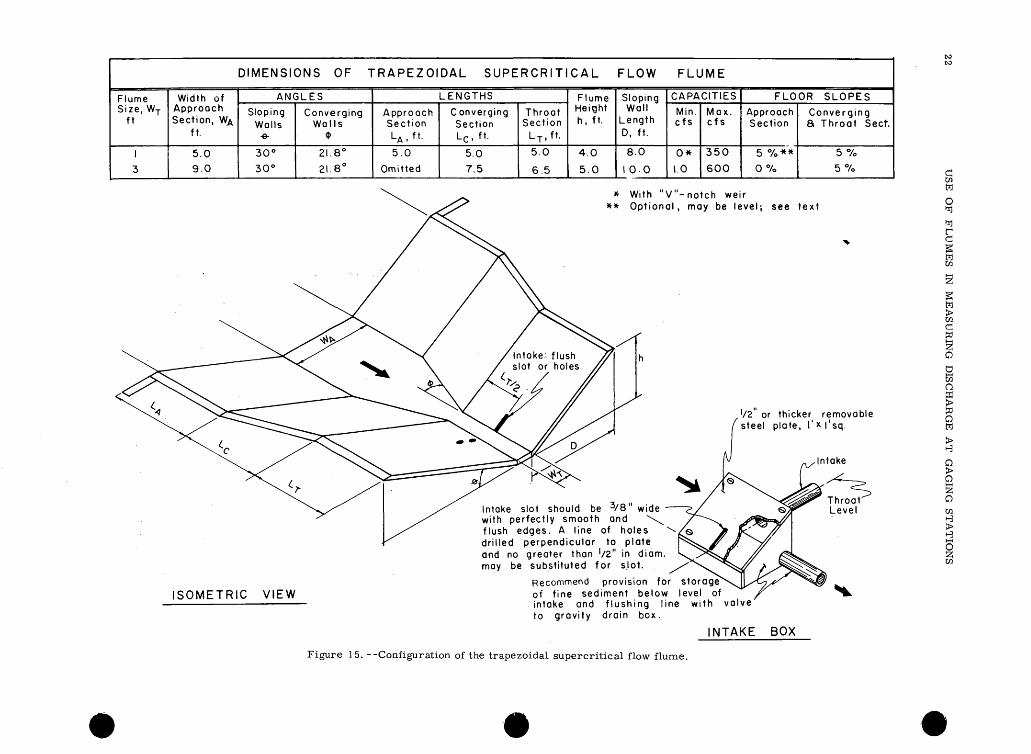
DIMENSIONS OF TRAPEZOIDAL SUPERCRITICAL FLOW FLUME
Flume Size, WT
ft
1
3
Width of Approach Section, W/\
ft.
5.0
9.0
ANGLES
Sloping Walls
e-
30°
30°
Converging Walls
<t>21.8°
21.8°
LENGTHS
Approach Section LA ,f».
5.0
Omitted
Converging Section LC- ft -
5.0
7.5
Throat Section
L T ,ft.
5.0
6.5
Flume Height h, ft.
4.0
5.0
Sloping Wall
Length D, ft.
8.0
1 0-0
CAPACITIES
Min. cfs
0*
1.0
Max. cfs
350
600
FLOOR SLOPES
Approach Section
5 %**
0 %
Converging & Throat Sect.
5 %
5%
Intake: flush slot or holes
* With "V"-notch weir ** Optional, may be level; see text
." or thicker removable steel plate, I' x I'sq.
ISOMETRIC VIEW
Intake slot should be 3/8" wide with perfectly smooth and \^ flush edges. A line of holes drilled perpendicular to plate and no greater than '/2 1 ' in diam. may be substituted for slot.
Recommend provision for storage of tine sediment below level of intake and flushing line with valve' to gravity drain box.
INTAKE BOX
Figure 15. --Configuration of the trapezoidal supercritical flow flume.

Ocrx h-
Q <LJX
o.uu
3.0O
2.00
1.000.80
0.60
0.40
0.20
O.IO 0.08 0.06
0.04
0.02
0.01
"Q N
m o
X. ^ 120°
^^-^^^^N^ ^S^~ #^1
ml'SI~ INSTALLATION OF I20°"V-NOTCH
WEIR AT END
To P
7 -
--«
" Line for
-Disch for ''
-
.Lin def
i
He)th
of w
-^ - '
^eir
.Zero
of 'fit
arc fk
|e jn
of fo
i
cri jm<
F
0
tic3
>lc
» '
P
a
-
3t
* *
IV
rating. IP j \
:ri1r 3
ic 5' 1al kirr
e-
OF FLUME
-^"^
^f^»** *~ "*"
Jotch
depth ^
r"iie'
is^^ ^
,*S'
/s''
' ,'
^
I
--
s
_/"
f s/
1
-
^
>*S"
_/
^L
-
x
jX*
^
=?c FlF
r»
X
^
.j
;^
Intake upstream in middle of throat
^Rating of I 1 flume with I2( "v"- Notch weir in-place
^
s
^x
*
'
« X1
S"
^/r^S
^s»
t n g For 3 ume Using ume As Moc
7=-
x'
X^
X?ati
i'
rel
i
^
^/
,
ng
-
'^
S'
t
F
^^x
r^
?
0
*
^
r
^
^
x
3
^
>
F
.» *^^ x s* ̂ s
r
"lumen
i
D oX
^
^~
\
It
^
^
$s#;
S
/
^*
9 *^^X
7/=L
I
I
1
y
' ^^<
/
^
/^
. L
/f
-^
,34 6 8 10
VELOCITY IN fps IN
i
FLUME
I
'
x -
-
-
-
-
,20 30
THROAT
1
-
3.0
2.0
1.0
0.8
0.6
0.4
0.2
O.I 0.08
0.05
.01 .02 .04 .06 O.I 0.2 0.4 0.6 1.0 2.0 4.0 6.0 10 20 40 60 100 200 400 800
DISCHARGE IN cfs
Figure 16. --Discharge rating curves and related data for one-and three-foot trapezoidal supercritical flow flumes.
ffi H
T) H N O
toCO

24 USE OF FLUMES IN MEASURING DISCHARGE AT GAGING STATIONS
This flume does not stictly conform in scale to that of the 1 -foot flume owing to certain practical limitations. The principal differ ence is in the throat length which is shorter than the 15 feet dictated by the three-fold in crease in scale. However the flume is es sentially a broad-crested weir and strict adherence to scale is not only impractical, but it is doubtful that exact hydraulic simi larity would be obtained. Experience with the 1-foot flume made the presence of the approach section of questionable value. For this reason the approach section L. (figure
A.
15), as originally designed for the 1-foot flume, was omitted in the case of the 3-foot flume, and the approximate configuration ofthe converging section, L, was extended by
Othe use of rock fill upstream to meet the natural channel banks. A level concrete floor was placed in the approach to the flume for use as a discharge measuring section.
This 3-foot flume has a range in discharge from 3 to approximately 600 cfs. The rating shown in figure 16 by the solid line was de veloped from that of the 1-foot flume using the Froude number criterion.
Recent discharge measurements made on this 3-foot flume do not check this rating but define the dotted curve shown on figure 16. As shown in the accompanying table of figure 15, the throat length for the 3-foot flume is only 6. 5 feet compared with 15 feet for the scaled-up 1 foot flume. The difference in ratings, as well as visual observation of the water surface at high flows, indicates that the throat length is too short and that the intake is too far upstream. The effect has been to measure head at high flows near the point where critical depth exists and perhaps even within subcritical flow. The .surging water surface and the widely fluctuating stage trace observed on the recorder at the higher flows would seem to varify this conclusion.
If the flume throat is lengthened to about 10 feet and the intake is placed at a distance of 6. 5 feet from the upstream edge of the throat section, the resulting rating should be close to that defined by the solid line rating for the 3-foot flume.
THE CONSTRUCTION AND OPERATION OF FLUMES
Stage Measurements
Velocities in the throat of the trapezoidal flume range from about 3 fps to in excess of 20 fps. Such high velocities are characteris tic of all critical- or supercritical-flow flumes and are necessary if the structures are to be kept clear of sediment, rock, and other debris. Such high velocities also make it impractical to place staff gages in the throat section although an overhead type wire- weight gage has been used successfully.
As a rule, regardless of how much large rocks and stones a stream carries, it also has fine sand and sediment which may be ex pected to enter the intake system. The bub bler gage improves response, lessens freezing problems, but will not remedy en tirely the sediment problem. All flumes, regardless of whether or not conventional intakes or bubbler gages are used should have provision for periodically flushing the intake system of fine sediment. The high elevation of most flumes makes it feasible to use a simple gravity drain flushing system.
If flumes are installed on streams where rapid changes in stage may be expected, in take lag may be a crucial factor. The bubbler gage will solve this problem and has been used successfully under such conditions by mounting the orifice within the intake box and not in the high-velocity flow.
Where conventional intakes are employed, lag time may be reduced by using large in takes, placing the gage stilling well as close to the flume as possible and making the diam eter of the stilling well as small as practical.
Regardless of whether conventional in takes or bubbler gages are used, considerable surge may be expected.
Discharge Measurements in Flumes
Most flumes have converging approach sections or other prepared sections where current-meter discharge measurements will

SUMMARY AND CONCLUSIONS 25
commonly be made. Experience has indi cated that contrary to what might be expected, such measurements may be poorer than if they had been made at a point in the natural channel. Some of the errors in these meas urements have occurred from failure to ob serve the following precautions:
1. The measuring section should prefer ably be in a region of parallel flow away from the flume throat. In the case of the Parshall flume, the measuring section would have to be in the converging section, but should be located 2/3 of the length of this section up stream from the throat, or opposite the up stream intakes.
2. Because of high velocities and inter ference from the presence of the engineer, measurements should be made from a bridge or plank across the flume with the meter suspended on a rod.
3. The floor in the approach section of most flumes is supposed to be uniform. There is therefore no compensation of depth readings due to rounding and all depths should be read to hundredths instead of tenths. Because of the high velocities, the most satisfactory method of measuring depth is to let the base plate of the wading rod touch the water sur face and then read on an auxiliary scale the distance through which the rod is lowered to the floor of the flume.
4. Widths should be measured accu rately to the nearest tenth of a foot with a graduated tape instead of a tag line. If the approach section is converging, the width should be measured through the center of the meter cups, not at the rod.
5. Velocity measurements should be made as close to each wall as possible, and again, half a foot from the walls, as the greatest variation may be expected in this region.
Winter Operation
Relatively small installations such as weirs and flumes have been successfully operated under severe winter conditions by the use of removable roof covers and liqui- fied-gas fueled infra-red heater systems.
The 3-foot trapezoidal flume as pre viously described has yielded ice-free records by means of such an installation. The limited experience to date indicates that the roof and
heater system should conform to the con figuration shown in figure 17. Extension of the roof a short distance over the approach section provides an ice-free measuring sec tion. The size of infra-red heater and gas tank depend on local climatic conditions and exposure. Cost of operation will generally be from $0. 25 to $0. 50 per day.
Construction Features
Flumes have customarily been construc ted of reinforced concrete, but concrete block, steel, and wood, have also been tried. Very high velocities and heavy sediment and debris loads demand that solid construction be employed. These high velocities also produce considerable uplift forces on the structures. Good concrete and good con creting techniques should be employed or erosion of the flume throat may be expected. Flume dimensions, especially those of the throat sections must be followed if precali- brated ratings are to be used.
SUMMARY AND CONCLUSIONS
The 4 flume designs covered in this re port are intended as precalibrated devices to be used where field ratings cannot be readily obtained. If precalibrated ratings are used, the structures must be carefully built to the exact dimensions specified. These factors necessarily increase the cost of such struc tures.
Evidence seems to indicate that the most critical dimensions for any of the flumes dis cussed are those of the throat. For critical - and supercritical-flow flumes, if a smooth, gradual transition from the natural channel, to the flume throat is accomplished, the stage-discharge relation for the flume will be essentially a function of the geometry of the throat.
In many instances, nondescript flume- type structures could be built where the self- cleaning features of flumes are needed if field rating is possible. The principles out lined early in the report should aid the en gineer in designing the structures to suit each specific need. The following pertinent design features should be kept in mind in the design of supercritical-flow flumes.
1. To obtain supercritical flow in the throat a floor slope of between 3 and 5% should be used.

26U
SE
O
F
FL
UM
ES
IN
M
EA
SU
RIN
G
DIS
CH
AR
GE
A
T
GA
GIN
G
ST
AT
ION
S
in o
o a.
CU 0)
. o_
oo «-
Is0) ~
<u
. cu
TJ
«»
3
O«
oe
O
O
°-
EE
cu
fc4-
TJ
CA O
= 1
°J£
°
O
c
Ww
-.
C
»c
cu£
E
o> _
oJ3TJ
O
O5
TJ
£ =
too -c
o ">
CA
<DE
o « g-
n
-S 10
O
O
«-
*sCU
0 T
J «
Oi
c
O
oo
<=
o
TJ
(A. (U
CU o
£
0)
o a>
O.O
_ o r E
5cuC
A
o Z
o
Q.
Q.
O «-
U
CA
CA
CX
o .t:
w -
o x^_
o
cuo
'"
w
°
«U w
«>
f o -21cu
(I) <U
>
oi
n T3
°= !"S
3
E
«
% - ^^c
o <_
<U t.
O »
-I ° I105
,,
So
c
*- »
w
r, CA
'cu
z. o
O
J3
CL
CU CA
0-«=
O
i^T
J
O
OT
J ~OT
J ~
§1
Ecu £
^
3
O
TJ
_Q
CU
0) w
Q
. >
2
«UT
J -O
^
>
O>
7 | «
O ^
"o
o o
2-
3 O
Q
. O
cu cu
^=V-
c «
O
4-
o«£ °
^
DL ^J (K
c .?§o
c U
UJ
oj ro
in to
rH
QJ
a
orH
0>rH
Q)
-sa;^0)irt*SrtT3 rH
O
IS1
Q)
a03rH
REFERENCES 27
2. Side walls at less than 30° are not recommended as adverse wave disturbances will result.
3. The approach floor or apron should be level or nearly so.
4. Smooth and gradually converging side wingwalls forming a gradual transition from the natural channel to the flume throat should be used. The flow must enter the flume smoothly. The flume should be care fully alined in the channel.
5. The flume length should not be ex cessive as a series of waves will be pro duced which will travel the length of the flume. The flume length should be between 2 and 3 times the maximum head at the meas uring section.
6. Head should be measured at about the midpoint of the throat. Intakes should be absolutely flush with the throat walls.
7. The flume should not contract the natural channel by more than a factor of two.
8. All flumes must be strongly con structed, usually of reinforced concrete. Unless they are constructed on bedrock, considerable scour protection downstream is essential.
9. Discharge measurement should not be made at sections immediately downstream of a flume or in the flume throat.
REFERENCES
Agr. Research Service, 1962, Field manual for research in agricultural hydrology: U.S. Dept. of Agr. Handb. 224.
Bermel, K. J., 1950, Hydraulic influenceof modifications to the San Dimas critical depth measuring flume: Amer. Geophys. Union Trans., v. 31, no. 5, p. 763-768, October.
Chamberlain, A. R., 1957, Preliminary model tests of a flume for measuring discharge of steep ephemeral streams: Colorado Agr. and Mech. Coll., Rocky Mountain Forest and Range Expt. Sta., CER57ARC12.
Cone, V. M., 1917, The venturi flume:Jour. Agr. Research, v. IX, no. 4, April 23.
Davis, Sydney, 1963, Unification of Parshall flume data: Am. Soc. Civil Engineers Trans., Paper 3511, v. 128, pt. 3, p. 339-421.
Dodge, R. A., Jr., 1963, Discussion ofUnification of Parshall flume data, by Davis, Sydney: Am. Soc. Civil Engineers Trans., Paper 3511, v. 128, pt. 3.
Kindsvater, C. E., Carter, R. W., and Tracy, H. J., 1953, Computations of peak discharge at contractions: U.S. Geol. Survey Circ. 284.
Parshall, R. L., 1926, The improved venturi flume: Am. Soc. Civil Engineers Trans., v. 89, p. 841-851.
,1932 and 1953, Parshall flumes oflarge size: Colorado Agr. Expt. Sta., Bull. 326; revised as Bull. 426A.
Robinson, A. R., 1957, Parshall measuring flumes of small sizes: Colorado Agr. and Mech. Coll., Agr. Expt. Sta., Bull. 61.
_______, 1959, Report on trapezoidal measuringflumes for determining discharge in steep ephemeral streams: Colorado Agr. and Mech. Coll., Rocky Mountain Expt. Sta., CER59ARR1.
Taylor, G. H., 1954, Portable venturi flume for measuring small flows: U.S. Geol. Survey, Water Resources Bull. 554, p. 29-30.
Wilm, H. G., Cotton, John S., and Storey, H. C., 1938, Measurement of debris- laden stream flow with critical-depth flumes: Am. Soc. Civil Engineers Trans., v. 103, p. 1237-1253.
Woodburn, J. G., 1932, Tests of broad- crested weirs: Am. Soc. Civil Engineers Trans., v. 96, p. 387.
GSA ATLANTA GA 66-2712