use and application of inflatable dam seals in large...
TRANSCRIPT

CDA 2001 Annual Conference Congrès annuel 2001 de l’ACB Fredericton, N.B./(N.-B.) Canada CANADIAN DAM ASSOCIATION September 30-October 4, 2001 ASSOCIATION CANADIENNE DES BARRAGES du 30 septembre au 4 octobre 2001
Use and Application of Inflatable Dam Seals in Large Concrete Dams
Guy Dickes: Constellation Group LLC, 6718 Chokeberry Road, Baltimore, MD 21209 USA
ABSTRACT: Inflatable dam seals have been successfully installed in numerous large concrete dams in the United States, and recently, for the first time, in Canada. One use of these small diameter seals is to minimize water intrusion due to failed waterstops in monolithic dams. The second, and more common use, is part of stress-related control of alkali-aggregate (or alkali silica) reaction (AAR, ASR) concrete problems associated with many large concrete dams. AAR problems cause concrete to expand. In massive concrete structures, such as dams, this creates many problems within the structure. Cracking of concrete and misalignment of equipment are two of the most prevalent issues that need to be addressed. A common repair method to alleviate stresses brought about by AAR on large concrete dams is a transverse vertical sawcut through the upper section of the concrete structure. Numerous dams throughout Canada and the United States have this problem. Cutting a dam from the upstream face to the downstream face presents one major challenge after the sawcut is complete— the control of the water flow through the 13-19 millimeter (1/2 to ¾ inch) kerf. Installation of inflatable dam seals with vertical heights of over 38 meters (125 feet) have successfully sealed failed waterstops and sawcuts in this situation. Each seal needs to be designed for the specific application. The composite construction seal has numerous elements to meet the necessary engineering requirements of Dam Safety Officials and Engineers and Owners. RÈSUMÈ: Les scellants gonflables de barrage ont été installés avec succès dans de nombreux grands barrages a bèton aux Etats-Unis, et récemment, pour la première fois, au Canada. Une des utilisations de ces scellants de petit diamètre est de réduire au minimum l'intrusion de l'eau due aux « waterstops » qui ont faillit dans les barrages monolithiques. Une deuxieme et plus commune utilisation, fait partie du control de constraintes dans les reactions d’agregats-Alkali ou agregats-slica du bèton. Ce dernier, constitue un problème dans plusieurs grand barrages a béton. Les problèmes associè avec la reaction AAR cause l’expansion du bèton. Dans les structures en béton, telles que les barrages, ceci crée des problèmes dans la structure. Craquement du béton et la déviation d'alignement du matériel, sont deux des questions les plus répandues qui doivent être abordées. Une méthode commune de réparation pour alléger les constraintes provoqués par la reaction AAR sur les grands barrages a bèton est de performer un coupore vertical, transversant la section supérieure de la structure en béton. Des barrages nombreux dans l'ensemble du Canada et des Etats-Unis souffrent de ce problème. La coupure du barrage du côtè ascendant au côtè descendant présente un défi principal après que la coupore soit complete, la controllant l'eau traversent le « kerf » dont la largeur est 13 à 19 millimètre (1/2 à ¾-inch). L'installation des scellants gonflables de barrage avec des hauteurs de plus de 38 mètres (125 feet) ont, avec succès, scellé les « waterstops » qui avait faillit ainsi que les « sawcuts » dans ce cas. Chaque scellant doit être conçu pour l'application spécifique. Les scellants, qui sont formè de materiaux composé, contiennent de nombreux éléments pour répondre aux exigences nécessaires d'ingénierie des fonctionnaires de sûreté de barrages, des ingénieurs et des propriétaires.

INTRODUCTION TO WATER STOPS
Inflatable dam seals have been successfully installed in numerous large concrete dams in the United States, and recently, for the first time, in Canada. One use of these small diameter seals is to minimize water intrusion due to failed waterstops in monolithic dams. The second, and more common use, is part of stress-related control of alkali-aggregate (or alkali silica) reaction (AAR, ASR) concrete problems associated with many large concrete dams. Failed Waterstops: Background
In the first case, monolith construction in dams require the installation of embedded waterstops to prevent water intrusion through the monolith construction joints. These joints have been traditionally divided into two classes—rigid and flexible. The rigid waterstops are typically metallic (steel, copper, and occasionally other materials). Flexible waterstops include materials such as PVC (polyvinyl chloride).
Copper was widely used by the United States Army Corps of Engineers (USACE) in their earliest dam construction projects. The copper was crimped or folded to provide for lateral movement between adjacent monolith sections. In the recent past, PVC has been more widely used by the USACE. In many cases, two waterstops are located in one joint, with an open drain located between them to relieve any water build-up that might develop.
An investigation by in 1985 of the USACE Waterways Experiment Station (McDonald and Campbell, 19851) damage and repair database revealed over 400 cases of water seepage at monolith joints during the inspection period.
In many cases, the improper installation of copper and PVC waterstops during the construction phase of large concrete dams create leaks into the working galleries of these dams. Errors in construction take the form of improperly placed waterstops, torn or missing waterstops, debris interfering with the waterstops, and honeycombing of the concrete in the vicinity of the waterstops. Additionally, waterstops improperly designed to handle the movement of the concrete structure are damaged after construction or settlement of the structure.
Thermal changes during seasonal changes can affect water leakage through failed waterstops. This has been documented at Harry S. Truman Dam, Warsaw, Missouri, USA. During the winter months, leakage at Monolith 5/6 joint increased to 300 gallons per minute. During the summer, leakage was reduced
to less than 10% of this figure. (Discussed in case histories.) Alkali-Aggregate or Alkali-Silicate Reaction: Background Alkali-aggregate reactions (AAR) in concrete may cause expansion and severe cracking of concrete structures. Although the mechanisms that cause AAR are not fully understood, it is generally accepted that certain aggregates (reactive silica) are reactive with the potassium, sodium, and calcium hydroxide found in cement. This reaction creates a gel around the aggregate. As this gel is subjected to moisture, it expands, creating forces that cause tension cracks to form around the aggregate. These forces are similar to those forces creating spalls around rusting reinforcing steel in concrete. The presence of AAR is easily identifiable in unconfined concrete by the telltale signs of surface map cracking on the exposed surfaces. Once cracking has started, moisture can easily penetrate the concrete, accelerating the alkali-aggregate reaction. The alkali-aggregate reaction may not be detected for many years before associated severe distress develops. Testing for alkali-aggregate reaction is performed utilizing petrographic analysis of the suspect concrete. More recent techniques involving uranyl-acetate fluorescence are economical and rapid. Large concrete dams, with a large array of mechanical equipment, are particularly susceptible to alkali-aggregate reaction problems. Sluice gates bind to the point of non-operation; waterstops tear; water distribution systems and power generating systems are pulled out of alignment; concrete slabs are pulled from their support beams; etc. Internal compressive stresses of the concrete in Fontana Dam, TVA reached 1000 psi (68 bar) in the outer 10 feet of the downstream face during the summer and 700 psi (47 bar) during the winter (Newell and Wagner, 19982). The most common technique seen to date to control the internal pressures created by alkali-aggregate reaction is to sawcut a slot in the concrete to allow it to expand. This definitely poses a problem when the dam is to impound perhaps millions of acre-feet of water. Failed Waterstop Remedial Efforts- A Brief History Numerous techniques have been tried, successfully and unsuccessfully, to control water passing through cracks, leaks and failed waterstops in dams. The United States Army Corps of Engineers undertook a major test study in an attempt to determine what

solutions worked in the field (McDonald and Campbell, 19851). Repairs discussed in the USACE report included such techniques as: • Rubber sheets on the upstream faces of the dam
(Algiers Lock, Louisiana, US, 1973) • Mechanically installed external waterstops with
backer-rod (MacArthur Lock, Michigan, US, undated).
• ‘U’ shaped water stops filled with sand-cement grouts; sealants (Michael J. Kirwan Dam, Ohio, US, 1970s)
• Surface mounted steel plate and joint filled with pumped cement grout (Clearwater Dam, Missouri, US, 1972)
• Removing the concrete key, packing the joint with oakum, sealing the oakum with lead wool and applying thin-ply concrete and grouting with cement/flyash grout. (Sardis Dam, Mississippi, US, 1966)
• Six-inch diameter grout-filled butyl tube installed- noninflatable and later fluid filled rubber tubes (Lock and Dam No. 3, Arkansas, US, 1969)
• Mechanical rubber stops and chemical polyurethane grout (John Day Lock, Oregon, US, 1982)
• Two-component rubber sleeve filled with water (Bagnell Dam, Missouri, US, 1984)—precursor to current inflatable waterstop.
The United States Army Corps of Engineer Report discusses numerous other attempts and outcomes of waterstop repair. This document should be reviewed by those interested in all techniques discussed. Remedial Efforts- Alkali-Aggregate Reaction “When the alkalis in the cement react with susceptible aggregate particles, a reaction rim of alkali-silica or alkali-carbonate gel is formed around the aggregate” (Vaysburd, 20003). This sums up the nature of the alkali-aggregate reaction problem. When exposed to moisture, the gel expands and increases the volume of concrete. Alkali-aggregate reaction in mass concrete sections causes severe stress, which in turn causes cracking of the concrete. Generally, the cracking is more severe than that caused by other types of deterioration. The severity of cracking appears to be a function of the rate of internal expansion, ambient environmental conditions and the degree of restraint present in a given concrete section. On initial investigation, drying of the concrete would be the most prudent approach to controlling the expansive process of AAR. This, however, is not a practical solution in large concrete dams. Other approaches to control the rate of alkali-aggregate
reaction is to limit the moisture reaching the concrete. This includes the application of surface sealers and membranes. This will prevent new moisture from reaching the concrete but will not reduce the moisture content already present. As AAR is already taking place, the moisture content is above the minimum required to keep the reaction going. Drying techniques have been tried in the United States but without success. Tests on five dams in the arid southwest region of the United States showed that even after 50 years of atmospheric drying, values for relative humidity exceeded the 85% threshold for expansion at depths as little as 0.5 to 1.0 inch (12 to 25 mm) from the exposed surfaces (Stark, etal, 19874) Other techniques for dealing with AAR include epoxy injection. This too presents a different set of problems. The epoxy will set-up hard, in most cases, having a compressive strength in excess of the concrete. This has the potential for increasing the internal stresses on the concrete, and, at a minimum, seals the moisture within the concrete. An examination of current literature will not provide substantial assistance in controlling alkali-aggregate reaction. At present, there are no known remedial techniques other than replacement, which in many cases is not a practical or affordable solution. With the understanding that AAR is an ongoing problem and will presents maintenance issues, a practical solution for dealing with alkali-aggregate reaction has to be utilized. Sawcutting of slots to relieve internal pressure is one of the more common remediation techniques. Depending on the structure, a continuous loop of diamond embedded wire is used to cut the concrete. This technique has been used in the United States and Canada. One of the first applications of diamond-wire technology to cut slots in a mass-concrete structure was in the intake structure at Mactaquac Generating Station (Thompson, 19906) and at the R.H. Saunders Generating Station in 1993. Tennessee Valley Authority has also used this technique at Hiwassee, Chickamauga and Fontana Dams. In many cases, the internal stresses are so great that the slots close up before the sawcutting can be completed, locking the diamond wire in place. In other cases, the sawcut closes up and must be recut to allow for future expansion. Typical slots are ½ to ¾ inch (12mm-19 mm) wide. ONE SOLUTION TO WATER INTRUSION In both cases of water intrusion-failed waterstops or intentionally installed saw cuts a practical solution needs to be put in place.
The dam seal now used is a multi-component monolithic unit capable of working in a large range of conditions under high head pressures and in all climates. By utilizing one basic design, accuracy and repeatability of success has been established. Numerous iterations have been designed, tested and used. The current design encompasses the best characteristics of all previously used designs. From the original seal used at Bagnell Dam to the latest pair of seals used at Mactaquac, rigorous testing and planning have developed this dam seal into the most reliable product of its kind. The typical application has been a 6 inch (152mm) or 8 inch (203mm) seal with lengths exceeding 125 feet (38 meters). Often, the diameter and length are decided by the Dam Engineer with input from the seal installation specialist. At Hiwassee Dam, TVA elected to use the 6 inch diameter seals (65 feet long), yet at Chickamauga and Fontana Dams, 8 inch seals are used (65 and 125 feet, respectively). These dams required seals for control of alkali-aggregate reaction issues. Please refer to case histories. At Harry S. Truman Dam in Warsaw, Missouri, the United States Army Corps of Engineers solicited a design-build solution. A six-inch seal was selected. At Mactaquac Generating Station, two inline 8-inch diameter seals were installed, selected by New Brunswick Power. Technical specifications for dam seals require attention to detail and extensive testing. After manufacturing, testing requires a minimum of one week to assure the seal will perform to expectations (see Table 1 for specifications). Not only must the seal meet the specified requirements, but also the contractor must be trained and experienced working in this field. Only absolute attention to detail will ensure complete success. The Dam Seal The current dam seal is a sophisticated, multi-component composite material specifically designed for the intended application. The dam seal has the misleading appearance of a rubber hose. Each dam seal is hand-built to exacting tolerances and inspected and tested to ensure that it will work precisely. The cost and effort to get to often remote located dams requires the contractor to be extremely accurate the first time. Minor mistakes can be very costly, both to the Owner and to the contractor. This dam seal is a multi-component composite to impart all the necessary functions for a successful installation. The seal must be flexible enough for
installation, be able to withstand significant temperature change, be durable to survive in a high alkalinity environment, be rugged enough to withstand thermal and dimensional changes in the dam, and be stiff enough not to extrude into the sawcut slot of up to 0.75 inches (19mm) at 125 foot and higher head pressure. In the case of the dam seals provided for Mactaquac Generating Station, the material must not be sensitive to exposure to propylene glycol. Propylene glycol was selected for the inflation medium in lieu of water due to the extreme cold weather experienced in Fredericton, New Brunswick, Canada and because of its environmentally friendly properties. Propylene glycol is commonly referred to at RV (recreational vehicle) antifreeze, suitable for potable water systems. The chemical selected offers freeze protection to –50 degrees Fahrenheit (-46 degrees Celsius). The dam seal inspection and testing process is time consuming. There is no substitute to performing a 72-hour pressure test to ensure an absolutely leakproof dam seal. The inspection process is performed by the most senior personnel in the Company. This inspection is critical to the success of a dam seal installation. A visual inspection of the entire length of the dam seal is performed prior to inflation on the shop floor. The dam seal is inflated with compressed air and the inlet valve sealed. Air pressure is recorded and monitored. The test is conducted for a minimum of 72 hours. This allows for even minor leaks to be detected. The dam seal is also inspected in its inflated form at this point for defects that would affect the performance of the seal. In the case of the dam seals provided for Mactaquac Generating Station, an independent inspector was contracted by New Brunswick Power. This engineer visited the test facility in Baltimore, Maryland to confirm and participate in the testing procedure. Table 1: Specifications of Dam Seals Seal Performance Requirements: • Elongation at free hanging weight: negligible • Construction: monolithic • Lateral expansion: >15% at 5 psi • Extrusion into 13mm slot at 100 foot head pressure:
(internal /external): less than 6mm • Environmentally safe product and filler • Seals must provide water tight seal • Seal must remain structurally intact at 150 feet of water
head-field conditions • Seals must be installed in one section and must be
removable

• Seals must be have proven long term durability • Seals must survive in a high alkalinity environment Quality Control / Proof Testing: • Individual seals must undergo 72 hour leak test at 3-5
psi- zero pressure loss (Figures 1, 2) • Individual seals must undergo vacuum leak test • Seal design must pass full scale mock-up tests,
replicating field conditions including: − Expansion − Elongation − Slot Extrusion
• Each bore hole, whether provided by Contractor or Owner, shall be video inspected full depth prior to seal installation
• Each seal shall be video inspected full depth after installation
• Installation must provide for safe conditions for environment upon completion
Contractor Experience: • Minimum of ten (10) years providing and installing
seals in large concrete dams • Contractor must prove ability to provide test apparatus
and facility to meet above requirements • Contractor must have annual revenue in excess of
$50million/annun
Safety: Contractor shall: • Provide OSHA Recordable, Lost Time Accident, Lost
Time Days and EMR information • Have a full time Safety Director • Have a proactive Safety Training Program for all
employees • Have a written Safety Program Engineering Principle The following paragraphs are from Structural Preservation Systems project submittal to the United States Army Corps of Engineers, Harry S. Truman Dam, Project DACW 41-98-C0016 (Dickes5): “The remedial waterstop system by SPS is unique in its simplicity and environmentally friendly nature. It has two major components, a rubber sleeve and water (H2O). It seals against passage of water through the vertical monolith joints while allowing movement between the monoliths. It is removable, reusable and or repairable. Because this joint is installed in existing structures, it is not subjected to the usual damage created during the construction operation. Its integrity is not contingent on embedment in wet concrete and
Figure 1: Air Testing - Day 3 GeoStructural Facility, Baltimore, Maryland
Figure 2: Seals Laid Out and Pressurized
GeoStructural Facility, Baltimore, MD

therefore not subject to problems with concrete shrinkage around the joint material. This waterstop works due to the differential pressures between the inside of the tube and the outside hydrostatic pressure. The rubber sleeve, sealed at the bottom and open at the top, is manufactured with an outside diameter equal to the interior of the drilled hole. After installation of the sleeve in the hole, it is filled with water up to the top of the sleeve; this is usually the top of the dam. Because the top of the sleeve is higher by several feet than the elevation of the water in the dam, the pressure inside the sleeve at any depth is greater than exerted on the joint by the pool water. This forces the sleeve tight against the sides of the hole and prevents passage of water through the vertical joint. Calculating the pressure differential is as follows: • Pressure on any point of the exterior of the joint -
upstream side: • Depth of water from surface x .5 = psi on exterior • Pressure on any point of the interior of the sleeve: • Depth from top of water in sleeve x .5 = psi on
interior • (Author’s Note: 0.5 psi is used for example only,
actual weight of water per square inch/foot is 0.43 pounds-GD)
• Example: differential pressure at elevation 665.0 with the pool elevation at 706 and the head of water in the sleeve at 757:
• Outside pressure = 706 – 665 = 41’ x .5 = 20.5 psi • Inside pressure = 757 – 665 = 92’ x .5 = 46.0 psi The tube material is sufficiently flexible to permit it to conform tightly to inside surface of the hole and strong enough to bridge the joint, up to ¼”, without extruding into the joint itself. In installations where there are concrete surface problems inside the hole or the joint is somewhat wider, a Neoprene sheet is installed around the outside of the tube for extra strength and abrasion resistance (Author’s Note: older design). Unlike some other tube type joints, this joint is removable and reusable. Because the interior is filled with water, it can be pumped out at any time. This will cause the tube to collapse below the pool water level and it can be pulled up, inspected, repaired, if necessary, and reinstalled. SPS has joints of this design that have been in place for over 10 years and are performing satisfactorily.” Borehole Requirements The borehole for dam seals is a critical part of the seal installation. In several cases, the seal installation specialist has performed the drilling operation; while in others, the borehole has been provided by others.
This will depend upon availability of a local drilling contractor, timing and contractual requirements for the project. In cases such as at Mactaquac Generating Station, where drilling precedes the concrete sawcutting operation, it was not practical to contract the drilling operation to the seal installation specialist. This was also the case at the Tennessee Valley Authority dams. At Harry S. Truman Dam, where SPS provided a design-build solution, the entire drilling and seal installation project was completed by in-house crews. It is imperative that the borehole be located in the correct position. For the sawcutting operation, location is not as critical as is the case for failed waterstop repair. In the failed waterstop remediation, it is imperative that the borehole follow the concrete cold joint, otherwise the seal will not be completely effective. With the sawcutting operation, the diamond wire follows the borehole. The borehole can be diamond cored or drilled with rotary pneumatic equipment. This decision is at the discretion of the Dam Owner and Engineer with input from the dam seal installer. The current dam seal design has performed successfully in both situations. It is crucial that the borehole walls be smooth for the dam seal to perform properly. In one instance, a local drilling firm using the wrong type of drill rod stabilizer performed the drilling. This created deep scour marks on the borehole wall. The borehole needed to be filled with grout and redrilled with the correct equipment. Subsequent holes at the same dam were drilled with the correct equipment without problems. In general, rotary pneumatic drilling is considerably less expensive than diamond coring. Diamond coring is generally accepted as being more accurate and true. In instances where absolute location of the borehole is critical (interference with equipment, galleries, tiebacks), then diamond coring should be selected. If location is not as critical, then rotary pneumatic drilling is more than adequate for the dam seals. It is a very important quality control step to inspect the borehole prior to dam seal installation. Boreholes with hanging rebar (reinforcing steel) have the potential for puncturing the seals. The bottom of the borehole must be below the lowest point of the sawcutting and clear of debris. This can best be determined by video inspection. If requested or required by the Owner or Engineer, a video tape recording can be performed for historical records. The video inspection allows for inspection of the concrete as well. Severe honeycombing of the concrete can be addressed prior to dam seal installation by grouting

and redrilling. This may be necessary along a cold joint in monolith dams when installing dam seals for a failed waterstop remediation. As discussed before, improper drilling techniques can scar the concrete, leaving deep gouges. This must be repaired prior to dam seal installation. Video inspection after dam seal installation is recommended. The immediate effect of the dam seal after installation is the true indicator of the success of the project thus final video inspection may be postponed. CASE HISTORIES Harry S. Truman Dam, Warsaw Missouri, US Harry S. Truman Dam is an earth/rock embankment concrete monolithic spillway located on the Osage River in central Missouri. Construction on the project began in 1964. It is approximately 125 feet high and 5,964 feet long. The concrete spillway is 964 feet long. Harry S. Truman Dam provides hydroelectric power (160 Megawatts) and recreational water activities for the region. It is the largest flood control lake in Missouri. During flood control operations, the pool is nearly 4 million acre feet. During normal operation, the pool impounds 1.2 million acre feet. In Spring 1998, the United States Army Corps of Engineers, Kansas City District, solicited, nationwide, competitive closed bids for design-build solutions for installing a remedial waterstop at Monolith 5/6. The copper waterstop installed during construction had failed and water was leaking into the gallery at a rate of 300 gallons per minute (1,125 liters per minute) during the cold winter months. Specifications were provided, but were flexible enough for three contractors to respond with bids. Structural Preservation Systems, Inc. was awarded the contract. The project specifications required the selected contractor to drill and install the remedial waterstop. The targeted depth of the remedial waterstop was below the bottom of Monolith 5 and into the underlying bedrock. A six inch diameter dam seal was selected. The drilling was performed using a Klemm 704 electric over hydraulic rotary drill rig. An air-powered down hole hammer provided the percussive force to drill the concrete. One of the requirements of the project was the methodical inspection of the borehole. For the first 40 feet of the bore hole, video and plumb-bob inspections had to be performed at 10 foot intervals.
This was very time consuming but necessary to ensure that the borehole remains centered on the cold joint. After the forty foot inspection was completed, inspection intervals were increased to 20 feet. For each inspection, the drill string (drill rods and down hole hammer) were withdrawn. Each inspection included a video camera inspection using a Geo-Vision Jr. borehole camera and a reverse plumb-bob to measure deviation from planned trajectory. Video recording and written record-keeping were mandatory. Deviations were noted during the drilling and minor corrections kept the drill string on track. Of utmost importance was staying centered on the cold joint. The drill string deviated 2 inches out of tolerance in an upstream direction. This has no effect on dam seal performance. Upon completion of the drilling operation, a final video inspection was performed with the United States Army Corps of Engineers in attendance. A small quantity of sand was lowered to the bottom of the hole to provide a smooth bed for the dam seal. The dam seal was lowered and subsequently filled with potable water. A video inspection of the filled dam seal completed the quality control portion of the project. A traffic-rated manhole cover was installed and grouted in place to complete the project. This dam seal was completed in August 1998, when ambient temperatures are in the 80-90 degree range. Leakage into the gallery was minimal during the summer months. Subsequent phone conversations with the USACE Engineer of Record, Mr. Leon Scheiber, revealed two important details. In January 1999 he indicated the flow into the gallery was negligible, as compared with 300 gallons per minute the previous year. In February 2000, a waterstop water elevation study was provided to the author. Elevations of the water varied over 5 feet. The United States Army Corps of Engineers was initially concerned with the dam seal system’s ability to adjust to relative seasonal movement. In a letter dated May 1, 2000 Leon Scheiber, USACE stated the following: “…the water level in the waterstop membrane fluctuates with the expansion and contraction of the concrete (expansion and contraction due to seasonal temperature change). The system has performed as we hoped. We have always been concerned with the relative seasonal movement at the monolith joints. The rubber membrane is flexible enough to articulate with the concrete as it expands and contracts. We were concerned with installing a less flexible waterstop system for this reason”.

Table 2: Harry S. Truman Dam Waterstop Manhole Reading
Date Feet 02/28/2000 4.750 01/24/2000 4.833 12/27/1999 4.330 11/30/1999 3.167 07/30/1999 0.708 06/02/1999 2.167 05/04/1999 3.400 04/15/1999 4.800 02/23/1999 5.400 01/29/1999 6.000 01/06/1999 5.000 11/23/1998 3.750
Based on the length and diameter of the dam seal, the seal undergoes an average 1/8 inch change is diameter (or ¼ inch at the surface and 0 inch change at the base). Tennessee Valley Authority: Multiple Locations Tennessee Valley Authority is the largest public producer of electricity in the United States. TVA manages an inventory of 29 hydroelectric, one pumped storage dams and 11 fossil fuel power plants. Additionally, Tennessee Valley Authority incorporates four ALCOA dams and eight United States Army Corps of Engineers dams into their power system. The TVA system is capable of generating nearly 30,000 megawatts. According to Electric Light and Power magazine, TVA power production costs were the third lowest among the top 25 producers in the United States. Tennessee Valley Authority service area is approximately 80,000 square miles. Tennessee Valley Authority has had dam seals installed for many years. In all cases, alkali aggregate reaction remedial efforts has been the determining factor. Hiwassee Dam, Cherokee County, North Carolina Hiwassee Dam was constructed between June 1936 and February 1940. Hiwassee impounds 422,000 acre feet at normal pool elevation and generates up to 117 megawatts of electricity. At Hiwassee Dam, two 6-inch diameter seals were installed at either end of the main spillway (Figure 3). These seals are approximately 65 feet long. TVA determined that this was the most optimum length affected by the alkali aggregate reaction stresses. As the mass of the dam increases, internal compression stresses overcome the alkali aggregate reaction
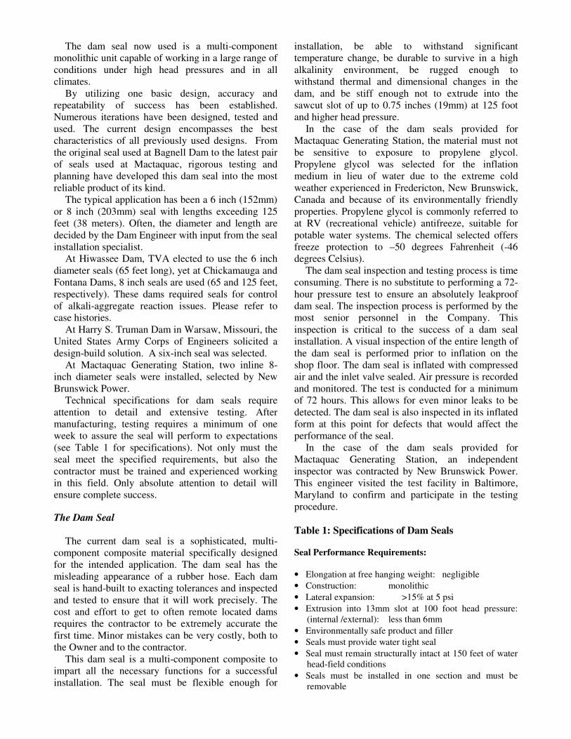
stresses and sawcutting and dam seals were no longer required. The Hiwassee seals were first installed in 1995, subsequently removed for additional sawcutting and new seals installed in 1999. As the alkali aggregate reaction continued, it was necessary to sawcut the dam upper spillway and redrill the boreholes. Chickamauga Dam, Hamilton County, Tennessee Chickamauga Dam was built between January 1936 and January 1940. Chickamauga’s reservoir has a capacity of 628,000 acre feet. The generating capacity at this facility is 111 megawatts. At Chickamauga Dam, one 8-inch diameter, 125-foot long seal was installed in 1999. Again, this was as a result of alkali aggregate reaction problems. The challenge at this dam was installing the seal under 80 feet of flowing water through the sawcut (Figures 4,5, 6, 7).
Figure 4: Water Flowing Through Sawcut
Chickamauga Dam, Tennessee
Water
Sawcut
Figure 3: Two Sawcuts, Either Side of
Main Spillway, Prior to Seal Installation Hiwassee Dam, Tennessee
Fontana Dam, Swain and Graham Counties, Tennessee Fontana Hydroelectric Dam, on the Little Tennessee River is 480 feet high and 2365 feet long. Constructed between January 1942 and November
1944, its reservoir impounds 1.44 million acre feet and generates 225 megawatts. Alkali aggregate reaction was identified during petrographic examination in 1972. Some of the more interesting alkali aggregate reaction facts at Fontana Dam: • 1000 psi compressive stresses in the outer ten feet
of the downstream face (during summer) 700 psi during the summer months were recorded.
• Stresses at greater depths were in the 300-500 psi range.
• Grouting and installing anchoring tendons were part of a program to control cracking.
• The first slot to remediate alkali aggregate reaction related stress in Block 32 was sawcut in 1976 and the upper portion was fully closed by 1983. The upper 50 feet was recut in late 1983. “Total permanent closure of the slot has been over 4 inches since the slot was initially cut in 1976 and by 1997 the slot had closed at the 50 foot depth” (Newell and Wagner2).
• Finite Element Analysis has been used to determine the optimum depth and location of sawcutting operations.
Two 8-inch diameter 65 foot long dam seals have been supplied to TVA for future installation in FY2001/2. Mactaquac Generating Station, New Brunswick Power, Keswick Ridge, Canada: Installation of Dam Seals at the Spillway EEP/Intake 6 Slot Mactaquac Generating Station generates 672 megawatts of electricity for the Maritime Provinces and is the second largest hydroelectric plant in Atlantic Canada. Construction started in 1965 and the first phase was completed in 1968. Subsequent components of the dam and powerhouse were completed in 1980. The Main Dam is has a crest length of 1700 feet and is a zoned embankment dam. The Intake Structure and Main Spillway are approximately 700 feet long. In 1973, movement was noted in a longitudinal joint in the Powerhouse. Movement was monitored but no remedial action was taken. In 1985, Gate 10 in the main spillway was made inoperable in the gate gains. Cracking was located at the east end pier of the spillway. In 1986, it was determined that alkali-aggregate reaction was creating concrete growth resulting in cracking and equipment misalignment and malfunction. An instrumentation program was designed and implemented, and a remedial plan was put into action. Gates and rollers were adjusted. Gates and gains have been monitored and adjusted. The steel staircase at
Figure 5: Immediately After Dam Seal Inflated Chickamauga, Tennessee
Figure 6: Seal Installed Chickamauga, Tennessee
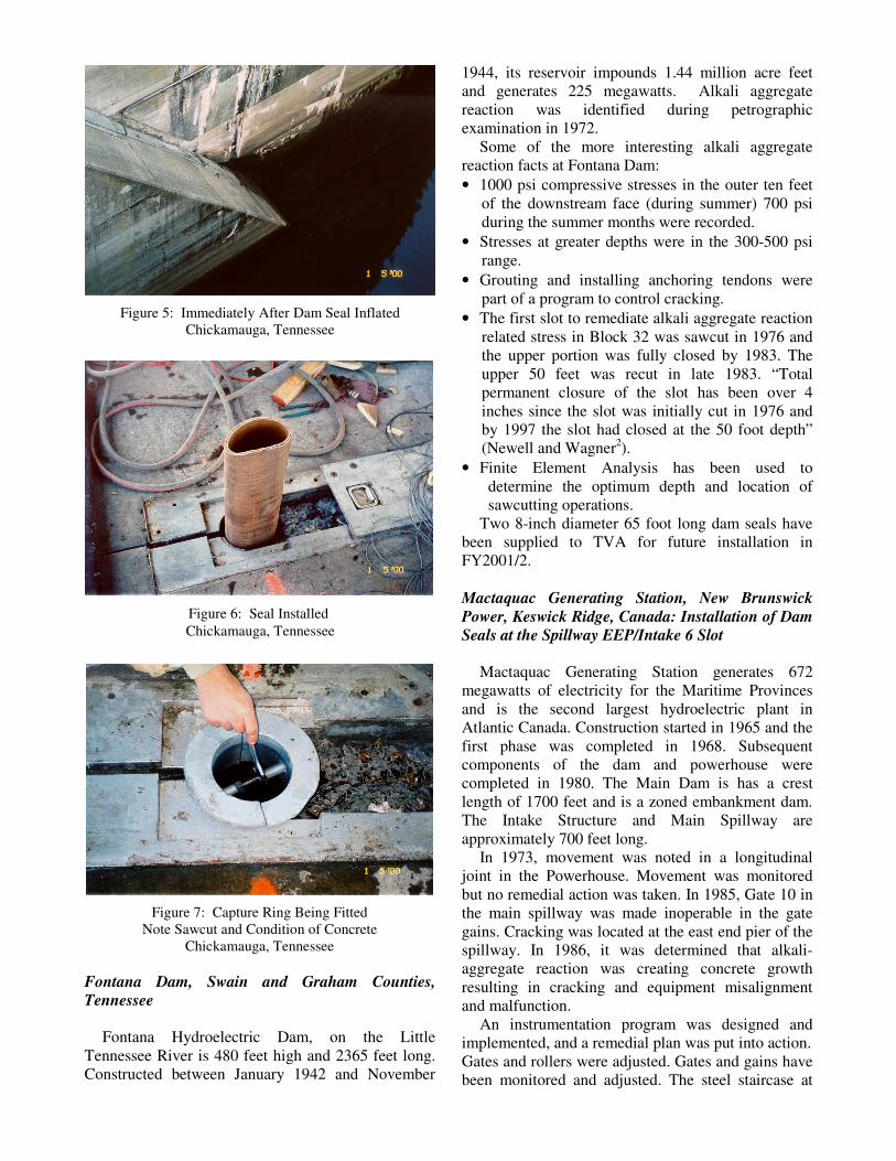
Figure 7: Capture Ring Being Fitted
Note Sawcut and Condition of Concrete Chickamauga, Tennessee

the east end of the main spillway was removed and the stairwell shaft was doweled and filled with reinforced concrete. Tendons were installed in 1988-1989 to increase the stability of the Intake Structure prior to sawcutting slots to relieve alkali-aggregate reaction stresses. Slots were cut in the Intake Structure between 1988 and 1992. Earliest cuts were performed with a 10mm diameter wire, whereas later cuts utilized a 13mm wire. It was necessary for two sawcut passes to provide clearance in some instances. Temporary cofferdams were initially installed to control water flow. Later attempts used a 36-inch diameter shaft and rubber belts to control water movement during the sawing operation. Numerous repairs have been made over the years to support internal structures. The history of concrete growth at Mactaquac is well documented (Gilks, 19976). In 1998, the author was contacted by Acres International, Niagara Falls, Ontario on behalf of New Brunswick Power to discuss the merits of small diameter dam seals. Engineering, references and cost data was provided at that time. In February 2000, proposals were solicited by New Brunswick Power. SPS was awarded a contract to provide two 100-foot (30 meter) 8-inch diameter dam seals. Unique to Mactaquac Dam was the requirement for two inline seals within one transverse sawcut (Figure 9). Of utmost importance was duplicity in seal integrity and not allowing any water to pass to the downstream face of the dam. This was accomplished by sawcutting only halfway through the dam at a time. The first dam seal was installed in Summer 2000 on the upstream portion of the dam. The sawcut was completed and the second seal was installed in December 2000 (Figures 8, 10, 11).
SUMMARY The need for large diameter holes and men bolting membranes in confined spaces or under water has been eliminated by surface drilling and installing a technologically advanced system. Hazardous working conditions have been minimized and time has been saved. Small diameter dam seals have proven to be an effective complement to sawcutting in the remediation of alkali aggregate reaction stresses in large concrete dams. A secondary, and often utilized, use is the remediation of failed waterstops in similar structures. Fast to install under varying conditions and extremely effective in shutting of water flow, these dam seals have proven their value time and time again.
Figure 8: Preparing the Seal for Installation
Mactaquac Generating Station Keswick Ridge, Canada
Figure 9: First Seal Installed Plywood Plate Covering Second Borehole
Mactaquac Generating Station
Figure 10: Measuring the Depth of the Borehole Is Critical to a Successful Dam Seal Installation
Mactaquac Generating Station

Figure 11: Second Seal Installed and Inflated
Mactaquac Generating Station ACKNOWLEDGEMENTS Mr. Vann Newell, Tennessee Valley Authority for his friendship and support Mr. Phillip Gilks, New Brunswick Power, Mactaquac Generating Station for his friendship and support The staff at Structural Preservation Systems Corporate Headquarters, Hanover, MD for their support in preparation of this paper. Mr. Peter Emmons, CEO, SPS for his leadership and vision. REFERENCES 1. MacDonald and Campbell, 1986 “Repair of Waterstop
Failures: Case Histories”, United States Army Corps of Engineers
2. Vann A. Newell and Charles D. Wagner, 1998. “Fontana
Dam, A Crack in the Curve” 3. Alex Vaysburd, 2000 “Rehabilitation”, ACI Committee 364,
FAQ #9 4. Stark, D., and DePuy, G., 1987 “Alkali-Silica Reaction in Five
Dams in Southwestern United States” ACI 5. Guy Dickes, 1998, Project Submittals, “Remedial Waterstop
Repairs at Monolith 5/6, Harry S. Truman Dam and Reservoir, Warsaw, Missouri”, United States Army Corps of Engineers, DACW-41-98-C0016.
6. Phillip Gilks, P.Eng. 1997. “Management of Concrete Growth at Mactaquac Generating Station”
Tennessee Valley Authority Library and website: background information New Brunswick Power website- background information United States Army Corps of Engineers website - background information Structural Preservation Systems, Inc. website- background information