usb on-the-go and embedded host automated … b-otg, capable of hnp and srp, state transition test...
TRANSCRIPT

USB On-The-Go and Embedded Host Automated
Compliance Plan
for the On-The-Go& Embedded Host Supplement Revision2.0
Version 1.2
July 27, 2012

USB On-The-Go and Embedded Host Automated Compliance Plan July 27, 2012 Version 1.2
1
Revision History
Revision Issue Date Comment
1.0 July 14, 2011 First release.
1.1 May 3, 2012 Additional Test Cases
Fixed editorial issues.
Added tests for EHs which don’t require test mode support.
Require a full battery for VBUS testing.
Simplifications to manual tests including removing some test peripherals, and only requiring up to 4 concurrent peripherals.
1.2 July 27, 2012 Changes to align the compliance plan with OTG Supplement Rev 1.2, v1.1a.
Clarification of test cabling characteristics.
Copyright © 2011, 2012, USB Implementers Forum, Inc.
All rights reserved.
A LICENSE IS HEREBY GRANTED TO REPRODUCE THIS SPECIFICATION FOR INTERNAL USE ONLY. NO OTHER LICENSE, EXPRESS OR IMPLIED, BY ESTOPPEL OR OTHERWISE, IS GRANTED OR INTENDED HEREBY.
USB-IF AND THE AUTHORS OF THIS SPECIFICATION EXPRESSLY DISCLAIM ALL LIABILITY FOR INFRINGEMENT OF INTELLECTUAL PROPERTY RIGHTS, RELATING TO IMPLEMENTATION OF INFORMATION IN THIS SPECIFICATION. USB-IF AND THE AUTHORS OF THIS SPECIFICATION ALSO DO NOT WARRANT OR REPRESENT THAT SUCH IMPLEMENTATION(S) WILL NOT INFRINGE THE INTELLECTUAL PROPERTY RIGHTS OF OTHERS.
THIS SPECIFICATION IS PROVIDED "AS IS" AND WITH NO WARRANTIES, EXPRESS OR IMPLIED, STATUTORY OR OTHERWISE. ALL WARRANTIES ARE EXPRESSLY DISCLAIMED. NO WARRANTY OF MERCHANTABILITY, NO WARRANTY OF NON-INFRINGEMENT, NO WARRANTY OF FITNESS FOR ANY PARTICULAR PURPOSE, AND NO WARRANTY ARISING OUT OF ANY PROPOSAL, SPECIFICATION, OR SAMPLE.
IN NO EVENT WILL USB-IF OR USB-IF MEMBERS BE LIABLE TO ANOTHER FOR THE COST OF PROCURING SUBSTITUTE GOODS OR SERVICES, LOST PROFITS, LOSS OF USE, LOSS OF DATA OR ANY INCIDENTAL, CONSEQUENTIAL, INDIRECT, OR SPECIAL DAMAGES, WHETHER UNDER CONTRACT, TORT, WARRANTY, OR OTHERWISE, ARISING IN ANY WAY OUT OF THE USE OF THIS SPECIFICATION, WHETHER OR NOT SUCH PARTY HAD ADVANCE NOTICE OF THE POSSIBILITY OF SUCH DAMAGES.
All product names are trademarks, registered trademarks, or servicemarks of their respective owners.

USB On-The-Go and Embedded Host Automated Compliance Plan July 27, 2012 Version 1.2
2
Contributors
Abel Astley Broadcom Corp. Daniel Wulcan Broadcom Corp. Salyl Bhagwat Broadcom Corp. Dan Ellis DisplayLink (UK) Ltd. Patrik Olesen Ericsson AB Marcin Behrendt Evatronix SA Pawel Eichler Evatronix SA Tomasz Klimek Evatronix SA Harry Peterson Evatronix SA Christopher Meyers Fresco Logic Inc. Peter Brink Intel Corporation Sridharan Ranganathan Intel Corporation Brad Saunders Intel Corporation Mike Micheletti LeCroy Corporation Paul Berg MCCI Corporation John Garney MCCI Corporation Greg Scaffidi MCCI Corporation Pat Crowe MQP Electronics Ltd. Sten Carlsen Nokia Corporation Maarit Harkonen Nokia Corporation Yauheni Kaliuta Nokia Corporation Richard Petrie Nokia Corporation (Chair) David Wu Nokia Corporation Panu Ylihaavisto Nokia Corporation Roshan Jhalani Sasken Communication Tech. Ltd. Yuva Kumar Sasken Communication Tech. Ltd. Srihari Sahyanarayana Sasken Communication Tech. Ltd. Mark Bohm SMSC Morgan Monks SMSC John Sisto SMSC Paras Agarwal ST-Ericsson Premnath Babu ST-Ericsson Nathalie Ballot ST-Ericsson Nicolas Florenchie ST-Ericsson Adam Burns Synopsys Inc. Vishwanath Kakarla Synopsys Inc. Sarah Boen Tektronix Inc. Pascal Berten Testronic Labs Ivo Huber Texas Instruments Grant Ley Texas Instruments

USB On-The-Go and Embedded Host Automated Compliance Plan July 27, 2012 Version 1.2
3
Table of Contents
1 Introduction 6 1.1 USB On-The-Go and Embedded Hosts 6 1.2 Objective of the Compliance Program 6 1.3 Scope of the Document 6 1.4 Intended Audience 6 1.5 Reference Document(s) 7
2 Acronyms and Terms 8
3 Executive Summary 11
4 Submission Materials 12 4.1 Checklists 12 4.2 Targeted Peripheral Lists 12 4.3 Device Specific Procedures 12 4.4 Interoperability Testing 12
4.4.1 Functional definition 12 4.4.2 TPL device(s) 12 4.4.3 Suspend support 12
5 OTG device support for the automated tester 13 5.1 Automated Testability Requirements 13
6 PET Automated Tests 14 6.1 PET – Protocol and Electrical Tester 14
6.1.1 Serial Interface Engine (SIE) 14 6.1.2 Electrical Test Board (ETB) 14 6.1.3 Script Processor 14 6.1.4 USB Analyzer 14
6.2 Test Cables Required 14 6.2.1 Special Test Cable A 15 6.2.2 Special Test Cable B 15
6.3 Test Set Ups 15 6.3.1 OTG device as Unit-Under-Test (Setup no. 1) 15 6.3.2 Embedded Host as Unit-Under-Test (Setup no. 2) 16 6.3.3 Peripheral Only as Unit-Under-Test (Setup no. 3) 17
6.4 User Input Before Test Runs 18 6.5 Pass Criteria 19 6.6 Parameter v Test Identifier 20 6.7 A-UUT Tests 24
6.7.1 ‘Get VBUS Turned On’ Sequence used in A-UUT Test Sequences 24 6.7.2 A-UUT Initial Power-up Test 28 6.7.3 Following Tests 30 6.7.4 A-UUT VBUS Voltage and Current Measurements 32 6.7.5 A-UUT Bypass Capacitance 34 6.7.6 A-UUT SRP 36 6.7.7 A-UUT HNP 38 6.7.8 A-UUT ADP 40 6.7.9 A-UUT Leakage 42 6.7.10 OTG A-device, Capable of ADP and SRP, State Transition Test 44 6.7.11 OTG A-device, Capable of ADP but not SRP, State Transition Test 49 6.7.12 OTG A-device, Capable of SRP but not ADP, State Transition Test 54 6.7.13 A-OTG, with no Session Support, State Transition Test 59 6.7.14 EH, Capable of ADP and SRP, State Transition Test (Standard-A) 63 6.7.15 EH, Capable of ADP but not SRP, State Transition Test (Standard-A) 65 6.7.16 EH, Capable of SRP but not ADP, State Transition Test (Standard-A) 67

USB On-The-Go and Embedded Host Automated Compliance Plan July 27, 2012 Version 1.2
4
6.7.17 EH with no Session Support State Transition Test (Standard-A) 69 6.7.18 EH, Capable of ADP and SRP, (Micro-AB) or OTG-A , Capable of ADP and
SRP but not HNP, State Transition Test 71 6.7.19 EH, Capable of ADP but not SRP, (Micro-AB) or OTG-A , Capable of ADP but
not SRP or HNP, State Transition Test 73 6.7.20 EH, Capable of SRP but not ADP, (Micro-AB) or OTG-A , Capable of SRP but
not ADP or HNP, State Transition Test 76 6.7.21 EH with no Session Support State Transition Test (Micro-AB), or OTG-A with
no Session or HNP Support. 78 6.7.22 A-UUT “Device No Response” for connection timeout 80 6.7.23 A-UUT “Unsupported Device” Message 82 6.7.24 A-UUT “Device No Response” for HNP enable 83 6.7.25 EH using Micro-AB “Incorrect Connection” 84
6.8 B-UUT Tests 85 6.8.1 B-UUT Initial Power-up Test 85 6.8.2 B-UUT VBUS Voltage and Current Measurements 87 6.8.3 B-UUT Bypass Capacitance 88 6.8.4 B-UUT SRP 89 6.8.5 B-UUT HNP 91 6.8.6 B-UUT ADP 93 6.8.7 B-UUT Leakage 95 6.8.8 B-OTG, Capable of ADP/HNP/SRP, State Transition Test 96 6.8.9 B-OTG, Capable of HNP and SRP, State Transition Test 100 6.8.10 OTG B-device, Capable of ADP and SRP only, State Transition Test 104 6.8.11 OTG B-device, Capable of SRP only, State Transition Test 106 6.8.12 OTG B-device, Capable of No Protocol, State Transition Test 108 6.8.13 ADP-Capable Peripheral Only B-device State Transition Test 110 6.8.14 SRP Only Capable Peripheral Only B-device State Transition Test 112 6.8.15 Peripheral Only B-device, Capable of No Protocols, State Transition Test 113 6.8.16 B-UUT “Device no response” for SRP 114 6.8.17 B-UUT “Unsupported Device” 116 6.8.18 B-UUT “Device No Response” for HNP 118
7 Manual Interoperability Tests 119 7.1 Introduction 119
7.1.1 What does “Category” mean? 119 7.1.2 What does “Prove Functionality” mean? 119
7.2 Interoperability Requirements 119 7.2.1 Targeted Peripheral List 119 7.2.2 Error messages 119 7.2.3 Hub support 119
7.3 Interoperability test definitions 120 7.3.1 A-UUT Functionality B-device 120 7.3.2 A-UUT Category Functionality B-device 121 7.3.3 A-UUT Boot test 122 7.3.4 A-UUT Legacy Speed test 122 7.3.5 A-UUT Concurrent and Independently test 123 7.3.6 A-UUT Unsupported device Message test 124 7.3.7 A-UUT Hub Error message test 125 7.3.8 A-UUT Hub Functionality test 125 7.3.9 A-UUT Hub maximum tier test 126 7.3.10 A-UUT Hub Concurrent and Independent test 127 7.3.11 A-UUT Bus powered hub power exceeded test 128 7.3.12 A-UUT Maximum concurrently device exceed message test 129 7.3.13 A-UUT Standby test 130 7.3.14 A-UUT Standby Disconnect test 130

USB On-The-Go and Embedded Host Automated Compliance Plan July 27, 2012 Version 1.2
5
7.3.15 A-UUT Standby Attach test 131 7.3.16 A-UUT Standby Topology Change test 132 7.3.17 A-UUT Standby Remote Wakeup test 133 7.3.18 OTG to OTG test 133
8 USB-IF Required Tests 135 8.1 Description of required tests 137
8.1.1 IOP Goldtree 137 8.1.2 Avg Current 137 8.1.3 USBCV 137 8.1.4 Back-Voltage 137 8.1.5 US HS Electrical 137 8.1.6 US FS SQT 137 8.1.7 Inrush 137 8.1.8 DS HS Electrical 137 8.1.9 DS FS SQT 138 8.1.10 DS LS SQT 138 8.1.11 Droop 138 8.1.12 Automated Test Ch6 138 8.1.13 Manual Test Ch7 138
8.2 Test procedures and tools 138
Table Listings Table 6-1 Special Test Cable A ..................................................................................................... 15 Table 6-2 Special Test Cable B ..................................................................................................... 15 Table 6-3: Information Obtained From Checklist ........................................................................... 18 Table 6-4: Information Required by PET to Compensate for Test Cables .................................... 19 Table 6-5: Which test procedures test which parameters .............................................................. 20 Table 6-6: Guide to abbreviations used in Table 6-5 ..................................................................... 24 Table 8-1: Embedded Host test requirements for Standard-A connector .................................... 135 Table 8-2: Embedded Host test requirements for Micro-AB connector ....................................... 136 Table 8-3: OTG device test requirements .................................................................................... 136 Table 8-4: EH B-Port and Peripheral-only B-device test requirements ....................................... 137
Figure Listings Figure 6-1 Setup No 1 – OTG device ............................................................................................ 16 Figure 6-2 Setup No 2 – Embedded Host ...................................................................................... 17 Figure 6-3 Setup No 3 – Peripheral Only ....................................................................................... 18

USB On-The-Go and Embedded Host Automated Compliance Plan July 27, 2012 Version 1.2
6
1 Introduction
1.1 USB On-The-Go and Embedded Hosts
USB has become a popular interface for exchanging data between a host PC and its peripherals. As computing resources have become less expensive, the line between PCs and other products has blurred. Today many devices that are not PCs in the classic sense have a need to connect directly to peripherals: Printers connect directly with cameras, for example, or mobile phones may need to connect to USB headsets. These non-PCs have the computing resources to manage a USB host function, but they need to function in ways that differ from standard PC hosts. Although they will provide host capability for some devices, it's unreasonable to require them to support the full range of USB peripherals. For example, connecting a camera to a printer makes a lot of sense, but the printer manufacturers may not think it is quite as important for the printer to support a USB GPS dongle. Because this is new territory for USB, developers need a way to understand what USB functionality they need to provide and what functionality is not required.
[USBOTG&EHv2.0] defines these non-PC hosts as Targeted Hosts. A Targeted Host is a USB host that supports a specific, targeted set of peripherals. The developer of each Targeted Host product defines the set of supported peripherals on a Targeted Peripheral List (TPL). A Targeted Host needs to provide only the power, bus speeds, data flow types, etc., that the peripherals on its TPL require.
There are two categories of Targeted Hosts:
1. Embedded Hosts: An Embedded Host (EH) product provides Targeted Host functionality over one or more Standard-A receptacles. Embedded Host products may also offer USB peripheral capability, delivered separately via one or more Type-B receptacles.
2. On-The-Go: An OTG product is a portable device that uses a single Micro-AB receptacle (and no other USB receptacles) to operate at times as a USB Targeted Host and at times as a USB peripheral. OTG devices must always operate as a standard peripheral when connected to a standard USB host.
The “USB On-The-Go and Embedded Host Automated Compliance Plan” ensures compliance with the added requirements of Targeted Hosts and peripherals which use protocols such as SRP and ADP.
1.2 Objective of the Compliance Program
The benefits of a compliance program have been proven by the USB initiative: the proliferation of knowledge, more stringent testing, and a higher standard of quality. The purpose of the “USB On-The-Go and Embedded Host Automated Compliance Plan” is to utilize the effectiveness of the USB-IF compliance program.
1.3 Scope of the Document
This document tests and/or checks for compliance with requirements specified in [USBOTG&EHv2.0].
1.4 Intended Audience
This specification is intended for developers of:
Embedded Hosts
OTG Devices
Peripherals which support SRP or ADP

USB On-The-Go and Embedded Host Automated Compliance Plan July 27, 2012 Version 1.2
7
1.5 Reference Document(s)
The following referenced documents can be found on the USB-IF website www.usb.org:
[BatteryCharging1.2] Universal Serial Bus Battery Charging Specification, revision 1.2
[Micro-USB1.01] Universal Serial Bus Micro-USB Cables and Connectors Supplement to the USB 2.0 Specification, revision 1.01.
[USB2.0] Universal Serial Bus Revision 2.0 Specification including ECNs and errata
[USB 3.0] Universal Serial Bus Revision 3.0 Specification including ECNs and errata
[USBOTG&EHv2.0] USB On-The-Go and Embedded Host Supplement, revision 2.0
[USBOTG&EHChecklist] USB On-The-Go and Embedded Host Checklist.
[USBCables2.0] USB Cables and Connectors Class Document, revision 2.0
[USBSystemsChecklist] USB Compliance Checklist, Systems
[USBPeripheralChecklist] USB Compliance Checklist, Peripheral (Excluding Hubs)
[USBPeripheralSilicon] USB Compliance Checklist, Peripheral Silicon (Excluding Hub Silicon)
[PET] Protocol and Electrical Tester (PET) specification

USB On-The-Go and Embedded Host Automated Compliance Plan July 27, 2012 Version 1.2
8
2 Acronyms and Terms
This chapter lists and defines terms and abbreviations used throughout this specification. Other terms and abbreviations are provided in [USBOTG&EHv2.0].
A-Device Device with a Standard-A receptacle or a device with a Micro-A plug inserted into its receptacle. The A-device supplies power to VBUS and is host at the start of a session. If the A-device is On-The-Go (equipped with a Micro-AB receptacle), it may relinquish the role of host to an On-The-Go B-device under certain conditions (see [USBOTG&EHv2.0]).
A-Host A-device acting in host role
A-Peripheral A-device acting in peripheral role
A-Port USB port with an A plug inserted into its receptacle. This port acts as an A-device.
ADP Attach Detection Protocol. A protocol which enables an OTG device or EH to detect when a remote device has been attached or detached (see [USBOTG&EHv2.0]).
ADP-capable Device which is able to perform ADP probing and ADP sensing 0 FP0F
1P.
ADP probing This enables the local A-device or B-device to probe VBUS and detect a change in attachment status.
ADP sensing This enables the local B-device to detect ADP probing generated by an attached device. ADP sensing is not a requirement for A-devices.
Application A generic term referring to any software that is running on a device that can control the behavior or actions of the USB port(s) on a device.
Attach This specification makes a distinction between the words “attach” and “connect”. A downstream device is considered to be attached to an upstream port when there is a physical cable between the two.
A-UUT Unit Under Test with a Micro-A plug attached.
B-Device Device with:
a Standard-B receptacle or,
Mini-B receptacle, or
Micro-B receptacle, or
Micro-AB receptacle with either a Micro-B plug or no plug inserted into its receptacle, or
a captive cable ending in a Standard-A or Micro-A plug.
The B-device is a peripheral at the start of a session. If the B-device is On-The-Go (equipped with a Micro-AB receptacle), it may be granted the role of host from an On-The-Go A-device (see [USBOTG&EHv2.0]).
B-Host B-device acting in host role
B-Peripheral B-device acting in peripheral role
B-Port USB port with a B plug inserted into its receptacle. This port acts as a
1 An ADP-capable EH is not required to do ADP sensing since it is not able to operate in the
B-device position.

USB On-The-Go and Embedded Host Automated Compliance Plan July 27, 2012 Version 1.2
9
B-device.
B-UUT Unit Under Test with a Micro-B plug attached.
Connect This specification makes a distinction between the words “attach” and “connect”. A downstream device is considered to be connected to an upstream port when it is attached to the upstream port, and when the downstream device has pulled either the D+ or D- data line high through a 1.5 kΩ resistor, in order to enter low-speed, full-speed or high-speed signaling.
EH Embedded Host.
Embedded Host A product that has a Standard-A or Micro-AB receptacle supported by a USB Host Controller. Embedded Hosts have a particular set of targeted peripherals, as described in their TPL.
FS Full Speed (as defined in [USB2.0]).
HS High Speed (as defined in [USB2.0]).
Host A physical entity that is attached to a USB cable and is acting in the role of the USB host as defined in [USB2.0]. This entity initiates all data transactions and provides periodic Start of Frames (SOF’s).
HNP Host Negotiation Protocol (see [USBOTG&EHv2.0]).
ID Identification. Denotes the pin on the Micro connectors that is used to differentiate a Micro-A plug (ID pin is FALSE) from a Micro-B plug (ID pin is TRUE). See [Micro-USB1.01] for details.
LPM Link Power Management (as defined in [USB2.0]).
LS Low Speed (as defined in [USB2.0]).
OTG On-The-Go.
OTG device Device that provides both host and peripheral capabilities over a single Micro-AB receptacle, as outlined in [USBOTG&EHv2.0].
Peripheral A physical entity that is attached to a USB cable and is currently operating as a “device” as defined in [USB2.0]. The peripheral responds to low level bus requests from the host.
Peripheral-only B-device
A device with a compliant B-side connector which can act only in peripheral mode.
PET Protocol and Electrical Tester. A test unit which is capable of performing the tests specified in Section 6.
Pre-session Calibration
ADP probe measurement taken when a pre-session measurement is not available. In this case, a measurement is taken, and a new session is initiated (or requested) to determine whether a remote device is attached.
SE0 Single Ended Zero (as defined in [USB2.0]).
Session The period of time that VBUS is powered (see [USBOTG&EHv2.0]).
SOF Start of Frame (as defined in [USB2.0]).
SRP Session Request Protocol (see Section [USBOTG&EHv2.0]).
SRP-capable Device which is able to generate or respond to SRP signaling.
Targeted Host A host that is only required to support the peripherals on its Targeted Peripheral List. OTG devices and Embedded Hosts both have

USB On-The-Go and Embedded Host Automated Compliance Plan July 27, 2012 Version 1.2
10
Targeted Host functionality.
Targeted Peripheral List
A list of USB peripherals that a particular Targeted Host can support (see [USBOTG&EHv2.0]).
TPL Targeted Peripheral List.
USB Universal Serial Bus.
USB-IF USB Implementers Forum (See www.usb.org).
UUT Unit Under Test

USB On-The-Go and Embedded Host Automated Compliance Plan July 27, 2012 Version 1.2
11
3 Executive Summary
The “USB On-The-Go and Embedded Host Automated Compliance Plan” does not overlap the USB 2.0 peripheral compliance plan. Any parameter/feature specified in the USB 2.0 Specification will not be tested here. The “USB On-The-Go and Embedded Host Automated Compliance Plan” will test only “New” parameters/features that are specified in [USBOTG&EHv2.0].
The significant features tested from [USBOTG&EHv2.0] are:
A Targeted Host capability
Session Request Protocol
Attach Detection Protocol
Host Negotiation Protocol
The ability to source at least 8 mA on VBUS
A means of communicating with the user
No Silent failures – i.e. there must be a method of alerting the user that an unsupported device has been attached, or that the attached device violates one of the conditions required to interface to the OTG device, e.g. it requires more current than the OTG device can provide.
Interoperability with devices on the Targeted Peripheral List defined for the UUT.
The details of these and other compliance tests are covered in subsequent sections of this document.
Many tests are based on the use of the Protocol and Electrical Tester (PET) as specified in [PET].
The USB-IF Board reserves the right to re-certify products if, after USB-IF certification, the TPL is updated such that this adds new capability to the device which has not previously been tested.

USB On-The-Go and Embedded Host Automated Compliance Plan July 27, 2012 Version 1.2
12
4 Submission Materials
4.1 Checklists
The manufacturer of an Embedded Host, OTG device or SRP capable peripheral shall provide a completed [USBOTG&EHChecklist] checklist plus any required additional USB Checklists depending on the type of product to be tested,
The [USBSystemsChecklist] (product and/or silicon) is required for an OTG device or EH. EHs with B-ports, OTG devices and peripherals supporting SRP/ADP (product and/or silicon) must also pass all standard USB-IF peripheral testing and so are required to supply a [USBPeripheralChecklist] and also a [USBPeripheralSilicon] when silicon is not yet certified.
4.2 Targeted Peripheral Lists
Targeted Hosts (both OTG devices and EHs) must provide Targeted Peripheral Lists before submitting the device for OTG and EH testing (see [USBOTG&EHChecklist]). The TPL shall include the list of supported products and hubs.
4.3 Device Specific Procedures
Testing in the absence of support for the automated test mechanisms specified in Section 5.1 is out of the scope of this compliance plan. The recommended approach to testing is to support these test mechanisms and to use the PET.
4.4 Interoperability Testing
The following sections detail the submissions which are required in order to complete Interoperability testing as defined in Section 7.
4.4.1 Functional definition
The A-UUT vendor is responsible for providing details of the expected functionality of the A-UUT.
4.4.2 TPL device(s)
The A-UUT vendor is responsible for providing the following TPL devices:
Each device listed on the TPL shall be provided.
When product is an EH with multiple ports 2 identical devices shall be provided.
When the product is an OTG device which supports hubs then 2 identical devices shall be provided as well as the hub or hubs listed on the TPL.
When the product is an OTG device which lists itself on the TPL2 identical products shall be provided.
All the listed TPL devices should be retail and USB-IF certified
4.4.3 Suspend support
The A-UUT vendor is responsible for providing the following details relating to suspend:
When the A-UUT supports USB suspend features (including LPM) there shall be an option to force the A-UUT in suspend during normal function in order to prove the suspend tests.
When remote wakeup is supported the A-UUT shall provide an option to enable this feature during suspend.
In case more types of suspend are supported the A-UUT shall be able to enter each suspend mode manually.
USB On-The-Go and Embedded Host Automated Compliance Plan July 27, 2012 Version 1.2
13
5 OTG device support for the automated tester
5.1 Automated Testability Requirements
An OTG A-device or B-device needs to behave in certain ways to assist with testing. [USBOTG&EHv2.0] allows immense freedom of behavior to devices which are covered by the specification, which could be a major barrier to automated testing, or even any testing at all of some particular parts of the specification.
In order for an OTG device or EH to be testable by automated equipment, a number of behavioral items must be satisfied. These can each be guaranteed by one of two approaches.
1) The behavior required is a normal part of device operation
2) The behavior required is forced by a special test mode
Details of the required automated test features are given in [USBOTG&EHv2.0].These behavioral requirements also apply to retail products obtained “off the shelf” since USB-IF retains the right to re-test any USB-IF certified shipping products at their point of sale.

USB On-The-Go and Embedded Host Automated Compliance Plan July 27, 2012 Version 1.2
14
6 PET Automated Tests
The tests in this section test only a partial list of all the possible parameters and compliant behavior. The tests should not be considered as a full validation test plan. It is the responsibility of the manufacturer of a device to verify compliance of their products according to [USBOTG&EHv2.0].
6.1 PET – Protocol and Electrical Tester
The PET is a unit, designed to perform compliance testing or assist with development work leading towards compliance testing on On-the-Go, Battery Charging and other general USB applications. It is described in detail in [PET].
A brief breakdown of its functional blocks follows.
6.1.1 Serial Interface Engine (SIE)
A fully functional SIE, with both host and peripheral capabilities, connected via a PHY to the PET socket labeled UUT (Micro-AB receptacle on the front panel). This is under the control of the Script Processor.
6.1.2 Electrical Test Board (ETB)
This contains circuitry to allow control and measurement of the electrical parameters for [USB2.0], [USBOTG&EHv2.0] and [BatteryCharging1.2]. It includes VBUS Generator, ID pin circuitry, data line test mode circuitry, VBUS current and voltage loads, and a variety of voltage and current measuring blocks. Extra connections are provided to enable the testing of Accessory Charger Adapters (ACAs).
6.1.3 Script Processor
Scripts are downloaded to this processor to control the sequence of operations required for a particular test. The processor controls the SIE and ETB as required by the operator. Scripts for all the [USBOTG&EHv2.0] and [BatteryCharging1.2] compliance tests would be provided by the application accompanying the PET.
6.1.4 USB Analyzer
The PET could also provide full USB analyzer functionality. By designing the analyzer into the PET circuitry the analyzer could be designed to have zero impact on the data line transmission quality.
6.2 Test Cables Required
The cables required by the PET tester are described below.
Each cable should be labeled, and specify the lead loop resistance value, required to be entered into the test dialog, if the cable is replaced. The tester application contains a check box to specify whether the UUT has a captive cable, as in this case the captive test cable is deemed to be part of the unit under test.

USB On-The-Go and Embedded Host Automated Compliance Plan July 27, 2012 Version 1.2
15
6.2.1 Special Test Cable A
Table 6-1 Special Test Cable A
Micro-B plug to Micro-B plug
Micro-B plug (PET) Micro-B plug (UUT) Purpose
1 1 VBUS
2 2 D-
3 3 D+
4 4 ID
5 5 GND
This cable has been specified to allow control of the ID pin of the unit-under-test. It is important to use this cable when the test specifies it. The cable has the following requirements:
The combined resistance of the Ground and the VBUS conductors (including all four connector contact resistances) shall be accurately measured at 500mA, and marked on the cable, so that its value may be entered into the PET test dialog.
The resistance of the Ground conductor (including both connector contact resistances) shall not exceed ROTG_ACA_GND (100mΩ) [BatteryCharging1.2].
The shield shall not be connected to the ground within the cable.
6.2.2 Special Test Cable B
Table 6-2 Special Test Cable B
Micro-B plug to Standard-A plug
Micro-B plug (PET) Standard-A plug (UUT) Purpose
1 1 VBUS
2 2 D-
3 3 D+
nc
5 4 GND
Although this is a standard cable configuration, the cable has the following requirements:
The combined resistance of the Ground and the VBUS conductors (including all four connector contact resistances) shall be accurately measured at 500mA, and marked on the cable, so that its value may be entered into the PET test dialog.
The shield shall not be connected to the ground within the cable.
6.3 Test Set Ups
6.3.1 OTG device as Unit-Under-Test (Setup no. 1)
When running a test-suite relating to an OTG device, the first test will prompt you to attach it to the PET using ‘Special Cable A’. This Micro-B plug to Micro-B plug cable is provided with

USB On-The-Go and Embedded Host Automated Compliance Plan July 27, 2012 Version 1.2
16
the PET unit and it is essential that a cable as specified above is used, for the following reasons:
It has 5 cores, instead of the usual 4. This allows the PET to control the ID pin of the UUT.
The resistance of this cable can be allowed for in tests involving large VBUS currents with measurements on VBUS current and voltage.
Figure 6-1 Setup No 1 – OTG device
OTGUnit-Under-Test
PET
PCHost for PET
Special Test Cable A
High Speed USB Link
6.3.2 Embedded Host as Unit-Under-Test (Setup no. 2)
When running a test-suite relating to an Embedded Host using a Standard-A receptacle, the first test will prompt you to attach it to the PET using ‘Special Cable B’. This Micro-B plug to Standard-A plug cable is provided with the PET unit and it is essential that a cable as specified above is used, for the following reason:
The resistance of this cable can be allowed for in tests involving large VBUS currents with measurements on VBUS current and voltage.
When running a test-suite relating to an Embedded Host using a Micro-AB receptacle, the first test will prompt you to attach it to the PET using ‘Special Cable A’. This Micro-B plug to Micro-B plug cable is provided with the PET unit and it is essential that a cable as specified above is used, for the following reasons:
It has 5 cores, instead of the usual 4. This allows the PET to control the ID pin of the UUT.
The resistance of this cable can be allowed for in tests involving large VBUS currents with measurements on VBUS current and voltage.

USB On-The-Go and Embedded Host Automated Compliance Plan July 27, 2012 Version 1.2
17
Figure 6-2 Setup No 2 – Embedded Host
Embedded HostUnit-Under-Test
PET
PCHost for PET
High Speed USB Link
Special Test Cable Aor
Special Test Cable B
6.3.3 Peripheral Only as Unit-Under-Test (Setup no. 3)
When running a test-suite relating to a Peripheral-Only OTG device, the first test will prompt you to attach it to the PET using ‘Special Cable A’. This Micro-B plug to Micro-B plug cable is provided with the PET unit and it is essential that a cable as specified above is used, for the following reason:
The resistance of this cable can be allowed for in tests involving large VBUS currents with measurements on VBUS current and voltage.
Another possibility is that the device has a captive cable with a Micro-A plug. In this case use this, and check the 'Captive Cable' check box, in the 'PET Test Suites' Dialog.
Finally, the device may have a captive cable with a Standard-A plug. In this case, use a suitable adapter to attach the Standard-A plug to the Micro-AB receptacle of the PET, and check the 'Captive Cable' check box, in the 'PET Test Suites' Dialog. The PET will apply any relevant VBUS test at the point of connection to the UUT, which means that the the UUT will be required to continue to function at VB_VBUS min (4V) at its connector, in spite of the extra voltage drop in its own cable.

USB On-The-Go and Embedded Host Automated Compliance Plan July 27, 2012 Version 1.2
18
Figure 6-3 Setup No 3 – Peripheral Only
OTG Peripheral-Only Device
Unit-Under-Test
PET
PCHost for PET
Special Test Cable A
High Speed USB Link
Captive Cable, or
6.4 User Input Before Test Runs
Before running any test suite, the PET needs to be informed of a number of parameters by the test operator. Most of the information should be available from the Checklist supplied by the vendor. The following tables describe the information required. Typically, PET software would modify the available options to those applying to the currently chosen device type.
Table 6-3: Information Obtained From Checklist
Input Type Purpose Checklist Ref
OTG Device Mutually exclusive check boxes
Automatically selected by UUT items OTG-A or OTG-B.
PI2 Embedded Host Automatically selected by UUT item Embedded Host.
Peripheral Only Automatically selected by UUT item Embedded Host.
Uses Micro-AB Check Box
Check this box for an EH which uses a Micro-AB receptacle instead of a Standard-A receptacle. It will be automatically selected for OTG devices.
PI5a
Supports Sessions Check box
Check this box if the OTG A-UUT or EH with Micro-AB receptacle does not keep VBUS enabled all the time that the ID pin is held low. Check this box for an EH with Standard-A receptacle which does not keep VBUS high all the time it is powered up. In either case it is assumed that SRP or ADP is available to detect the presence of a device.
PI10
SRP as A-device Check box
Check this box if the UUT, as an A-device, supports detecting, and acting on, an SRP pulse generated by a connected device.
PI13
HNP as A-device Check box
Check this box if the UUT, as an A-device, supports HNP to enable the connected B-device to become host if it so requires.
PI13
HNP Polling as A-device
Check box
Check this box if the UUT, as an A-device, supports HNP polling. If it does it is allowed to remain as host, for as long as the other device does not set its Host Request Flag.
PI13
ADP as A-device Check Check this box if the UUT, as an A-device, supports ADP probing PI13

USB On-The-Go and Embedded Host Automated Compliance Plan July 27, 2012 Version 1.2
19
box to detect the presence or otherwise of a connected device.
SRP as B-device Check box
Check this box if the UUT, as a B-device, supports generating an SRP pulse in order to start a session (cause the connected A-device to turn on VBUS).
PI20
HNP as B-device Check box
Check this box if the UUT, as an B-device, supports HNP to allow it to become host if it so requires.
PI20
ADP as B-device Check box
Check this box if the UUT, as an B-device, supports ADP sensing and probing to detect the presence or otherwise of a connected device.
PI20
FS Not Available Check box
Check this box if UUT does not fully support full-speed operation. This is not permitted for an OTG device, but may be for an Embedded Host.
PI11, PI18
IA_VBUS_RATED Edit box The rated output current of an A-device in mA units. PI8
bMaxPower Edit box bMaxPower (sic) is the highest current, in mA, declared in any of the device's Configuration Descriptors. This value ignores current drawn under the Battery Charging provisions.
PI17
TPWRUP_RDY Edit box Maximum time, in seconds, specified by vendor from powering on the UUT until it is ready to perform USB functionality. By default this is set to 30 seconds, but a vendor is permitted to specify a longer time.
PI24
TA_WAIT_BCON max Edit box The maximum time, in seconds, that VBUS is left on for by an A-device, in the absence of a B-device connecting. The default value is thirty seconds. A vendor is permitted to specify a longer time, but should be aware that this will have an impact on the time taken for, and therefore possibly the cost of, compliance testing.
PI10
Unknown Dev (No HNP)
Edit boxes
The test will use the VID/PID combination specified during tests for error messages, when an unknown B-device, not capable of HNP, is connected. A default value (1A0A/0201) is used, but any other device not on the UUT's TPL may be defined here.
-
Unknown Dev (HNP)
Edit boxes
The test will use the VID/PID combination specified during tests for error messages, when an unknown B-device, capable of HNP, is connected. A default value (1A0A/0202) is used, but any other device not on the UUT's TPL may be defined here.
-
Table 6-4: Information Required by PET to Compensate for Test Cables
Input Type Purpose
Cable A Edit box Test Cable A loop resistance in mΩ.
Cable B Edit box Test Cable B loop resistance in mΩ.
6.5 Pass Criteria
In the some of the test sequences which follow, a particular form of wording has been used, to ensure that the pass criteria are clear. Wherever the word 'check' is used, this defines a timing or behavior requirement that must be satisfied for the overall test sequence to be deemed to have been passed. The failure to satisfy any one of these 'checks' results in a failure for the test sequence in question.
For example, in the following test sequence fragment, two pass criteria are implicitly defined by use of the word 'check'. Failure of either one results in a failure for the complete test sequence.
...
7. Check for VBUS on within TPWRUP_RDY (30s)

USB On-The-Go and Embedded Host Automated Compliance Plan July 27, 2012 Version 1.2
20
8. Check it remains on for TA_WAIT_BCON min (1.1s)
...
In tests where there is some interaction required from the operator in order to validate a test pass then a specific pass criterion is listed at the start of the test. In the example:
…
7. Display Message "Click OK if 'Unsupported Device’ indication displayed on UUT".
8. If operator clicks OK before 30s timer expires, then UUT passes test.
…
The pass criterion would be “Message “Unsupported Device” or similar is displayed on UUT”.
6.6 Parameter v Test Identifier
Table 6-5 identifies which test procedure(s) result in each of the parameters specified in [USBOTG&EHv2.0] being tested. Not all parameters can be directly measured.
Table 6-5: Which test procedures test which parameters
Parameter Symbol Tested In Comments
VBUS Voltage:
VBUS Average Voltage (low power)
VA_VBUS_AVG_LO A-UUT VBUS Both min and max tested.
VBUS Average Voltage (high power)
VA_VBUS_AVG_HI A-UUT VBUS Both min and max tested.
VBUS transient voltage (low power)
VA_VBUS_TRNS_LO A-UUT VBUS Both min and max tested.
VBUS transient voltage (high power)
VA_VBUS_TRNS_HI A-UUT VBUS Both min and max tested.
B-device operating voltage
VB_VBUS B-UUT VBUS Both min and max tested.
OTG device or EH Leakage Voltage
VOTG_VBUS_LKG A-UUT SRP B-UUT SRP
Only has a max. This is tested.
ADP discharge voltage
VADP_DSCHG A-UUT ADP B-UUT ADP
Only has a max. This is tested.
VBUS noise requirement for ADP
VADP_NOISE - Not Tested. (Checked by confirmation of correct operation.)
VBUS Current:
A-device Output Current
IA_VBUS_OUT
IA_VBUS_RATED
A-UUT VBUS The value which is actually tested is IA_VBUS_RATED
which is specified by the vendor to be less than or
equal to IA_VBUS_OUT max, and greater than or
equal to the larger of IA_VBUS_OUT min and bMaxPower (part of the bmAttributes field of the Standard Configuration Descriptor as defined in [USB2.0] or [USB 3.0]) of any peripheral on the TPL of the UUT. The PET limits the maximum value of
IA_VBUS_RATED to 1.8A to avoid damage to USB
connectors.
B-device (OTG device or SRP-
IB_UNCFG B-UUT VBUS Only has a max. This is tested.

USB On-The-Go and Embedded Host Automated Compliance Plan July 27, 2012 Version 1.2
21
Parameter Symbol Tested In Comments
capable peripheral-only) Unconfigured Average Current
VBUS leakage source current
IVBUS_LKG_SRC A-UUT LKG Only has a max. This is tested.
ADP source current IADP_SRC A-UUT ADP B-UUT ADP
Both min and max tested.
ADP sink current IADP_SINK - Not measured. However its effect is proved by the
measurement of VADP_DSCHG
Terminations:
VBUS resistance ROTG_VBUS A-UUT LKG B-UUT LKG
Only has a min. This is tested.
Thresholds:
OTG device Session Valid
VOTG_SESS_VLD B-UUT VBUS Both min and max tested
ADP probing voltage VADP_PRB A-UUT ADP B-UUT ADP
Both min and max tested
ADP sensing voltage VADP_SNS - Not directly measurable.
Capacitance:
OTG A-device or EH VBUS bypass capacitance
CA_VBUS A-UUT CAP Min is tested.
VBUS bypass capacitance for ADP capable devices
CADP_VBUS A-UUT CAP B-UUT CAP
Both min and max tested
ADP threshold capacitance
CADP_THR A-UUT ADP B-UUT ADP
Both min and max tested
VBUS bypass capacitance for non-ADP capable devices
CRPB B-UUT CAP Both min and max tested
DC Electrical Timing:
Period of measurement for
VA_VBUS_AVG_LO
and
VA_VBUS_AVG_HI
TAVG_VBUS - Not a parameter to measure, but a specification for performing a measurement.
Used in A-UUT VBUS Used in B-UUT VBUS
VBUS Rise Time TA_VBUS_RISE A-UUT VBUS (in A-UUT GVBO)
Only has a max. This is tested.
Session end to
VOTG_VBUS_LKG TSSEND_LKG A-UUT LKG
B-UUT SRP A-ST-TRANS
Only has a max. This is tested.
Time to detect device attachment and turn on VBUS
TA_VBUS_ATT
A-UUT ADP (in A-UUT GVBO) and A-ST-TRANS
A-UUT ADP
-
Only has a max.
Case 1: Non ADP – ID pin goes FALSE.
VBUS turn on within TA_VBUS_ATT
Case 2: ADP capable – capacitance change.
VBUS turn on within TA_VBUS_ATT
Case 3: ADP Startup. VBUS on after an initial ADP probe. Not testable as ADP probe cannot be

USB On-The-Go and Embedded Host Automated Compliance Plan July 27, 2012 Version 1.2
22
Parameter Symbol Tested In Comments
detected when immediately followed by VBUS on.
Common:
Local Disconnect to Data Line Discharge
TLDIS_DSCHG - Not directly measurable
ADP cycle to cycle jitter
TADP_PRB_JTR A-UUT ADP B-UUT ADP
Only has a max. This is tested.
Power on until ready for USB (not mandatory see reference)
TPWRUP_RDY A-UUT PUT B-UUT PUT
Only has a max. This is tested.
A-device:
SRP Response Time TA_SRP_RSPNS A-UUT SRP Only has a max. This is tested.
B-Connect Long Debounce
TA_BCON_LDB A-UUT SRP Only has a min. This is tested.
B-connect to A-reset TA_BCON_ARST A-UUT HNP Only has a max. This is tested.
Wait for B-Connect TA_WAIT_BCON A-UUT VBUS Max value used in many places to infer when a test has failed. Min value tested in test indicated
A-Idle to B-Disconnect
TA_AIDL_BDIS A-UUT HNP Only has a min. This is tested.
B-Disconnect to A-Connect
TA_BDIS_ACON A-UUT HNP Only has a max. This is tested. Also used in B-UUT.
B-Idle to A-Disconnect
TA_BIDL_ADIS A-UUT HNP Both min and max tested.
B-Connect Short Debounce
TA_BCON_SDB - Internal to A-device. Cannot be measured.
B-Connect Short Debounce Window
TA_BCON_SDB_WIN - Internal to A-device. Cannot be measured.
A-device ADP probing period, (Typical = 1.75s)
TA_ADP_PRB A-UUT ADP Both min and max tested.
Session end to ADP probing
TA_SSEND_PRB A-UUT PUT A-UUT ADP
Only has a max. This is tested.
B-device:
Session end to SRP init
TB_SSEND_SRP B-UUT SRP Only has a min. This is tested.
SE0 Time Before SRP
TB_SE0_SRP B-UUT SRP Only has a min. This is tested.
Data-Line Pulse Time TB_DATA_PLS A-UUT SRP B-UUT SRP
Both min and max tested.
SRP Fail Time TB_SRP_FAIL B-UUT PUT B-UUT SRP B-UUT DNR
Min tested in B-UUT PUT and B-UUT SRP. Max functionally tested in B-UUT DNR.
Session Valid to B-Connect
TB_SVLD_BCON B-UUT SRP Only has a max. This is tested.
A-Idle to B-Disconnect
TB_AIDL_BDIS B-UUT HNP Both min and max tested.
Time between B-device HS to FS transition during suspend, and B-
TB_FS_BDIS B-UUT HNP Both min and max tested.

USB On-The-Go and Embedded Host Automated Compliance Plan July 27, 2012 Version 1.2
23
Parameter Symbol Tested In Comments
device disconnect
A-SE0 to B-Reset TB_ASE0_BRST - Time to optional event – not tested.
A-Connect Debounce TB_ACON_DBNC - Not a practical test – check by vendor declaration.
A-Connect to B-SE0 TB_ACON_BSE0 B-UUT HNP Only has a max. This is tested.
B-device ADP probing period (Typical = 2.0s)
TB_ADP_PRB B-UUT PUT B-UUT ADP
Both min and max tested.
Time from stopping ADP probing to SRP generation
TB_ADP_PRB_SRP B-UUT ADP Only has a max. This is tested.
B-device ADP detach time, sensing mode
TB_ADP_DETACH B-UUT ADP Both min and max tested.
Sensing end to first ADP probe
TB_SNSEND_PRB B-UUT ADP Only has a max. Not independently testable, but
tested in conjunction with TB_ADP_DETACH max.
Testability
Bus reset to configuring test device
TTST_CONFIG A-UUT VBUS A-UUT SRP
Only has a max. This is tested.
Maintaining configured session on test device
TTST_MAINT - Used to allow testing in A-UUT VBUS.
B-device as host, SetConfiguration() to suspend of test device
TTST_SUSP B-UUT HNP Only has a max. This is tested.
Session end to SRP from unit under test
TTST_SRP B-UUT SRP Only has a max. This is tested.
‘otg_hnp_reqd’ flag set to Host Request Flag set
TTST_HNP B-UUT HNP Only has a max. This is tested.
Reconnect after handing back control from HNP caused by ‘‘otg_hnp_reqd’
TTST_HNPEND B-UUT HNP Only has a max. This is tested.
Time to switch off VBUS after tester disconnects with ‘otg_vbus_off’set
TTST_VBOFF A-UUT CAP Only has a max. This is tested.
VBUS off with no ADP after session which sets ‘otg_vbus_off’
TTST_NOADP - Min used to allow testing in A-UUT CAP.
HNP Polling
Polling period for the event flags
THOST_REQ_POLL A-UUT HNP Both min and max tested.
Time from detection of host flag until suspend
THOST_REQ_SUSP A-UUT HNP Both min and max tested.

USB On-The-Go and Embedded Host Automated Compliance Plan July 27, 2012 Version 1.2
24
Table 6-6: Guide to abbreviations used in Table 6-5
Abbreviated Name Full Name
A-UUT GVBO Get VBUS On Function
A-UUT PUT A-UUT Initial Power Up Tests
A-UUT VBUS A-UUT VBUS Voltage and Current Measurements
A-UUT CAP A-UUT Bypass Capacitance
A-UUT SRP A-UUT Session Request Protocol
A-UUT HNP A-UUT Host Negotiation Protocol
A-UUT ADP A-UUT Attach Detection Protocol
A-UUT LKG A-UUT Leakage
A-ST-TRANS Appropriate A-UUT State Transition Test
B-UUT PUT B-UUT Initial Power Up Tests
B-UUT VBUS B-UUT VBUS Voltage and Current Measurements
B-UUT CAP B-UUT Bypass Capacitance
B-UUT SRP B-UUT Session Request Protocol
B-UUT HNP B-UUT Host Negotiation Protocol
B-UUT ADP B-UUT Attach Detection Protocol
B-UUT LKG B-UUT Leakage
B-UUT DNR B-UUT “Device No Response”
6.7 A-UUT Tests
6.7.1 ‘Get VBUS Turned On’ Sequence used in A-UUT Test Sequences
The following sequences are used in most of the A-UUT tests, to bring the UUT to the point of applying VBUS. As the test sequences themselves are tests of functions which can be required on more than one UUT type, it is necessary to use different procedures, depending on the capabilities of the UUT in question. The procedure depends on whether the UUT is:
OTG A-device which supports sessions and is capable of ADP and SRP
OTG A-device which supports sessions and is capable of ADP but not SRP
OTG A-device which supports sessions, is capable of SRP but not ADP
OTG A-device which does not support sessions
EH which supports sessions and is capable of ADP and SRP
EH which supports sessions and is capable of ADP but not SRP
EH which supports sessions and is capable of SRP but not ADP
EH which does not support sessions
In the actual tests, these sequences are indicated by: ‘Get VBUS Turned On’
At the start of most A-UUT tests, the main aim is to get VBUS on as soon as possible. One of the main potential delays in performing A-UUT tests originates with TA_WAIT_BCON max, which can mean waiting 30s or more between tests for VBUS to go off, so that we can turn it on, knowing that it will then stay on for at least TA_WAIT_BCON min (1.1 Sec).

USB On-The-Go and Embedded Host Automated Compliance Plan July 27, 2012 Version 1.2
25
The alternative approach we use in the following A-UUT test sequences is to observe at the start of a test whether VBUS is already on (still on from the previous test). If not, we invoke the ‘Get VBUS Turned On’ sequence. Otherwise, we proceed with the next step, which is to connect. After connecting we check whether VBUS is still on. If it is we proceed with the test, otherwise we disconnect D+, invoke the ‘Get VBUS Turned On’ sequence, and then connect again. To avoid an infinite loop, we restrict the use of ‘Get VBUS Turned On’ to one attempt.
Note that for simplicity, this procedure is not described in detail in the A-UUT tests.
In general, the tests can now proceed without delay in between tests.
An important point to note is that VBUS may stay on for two different possible times. If the test device 0x1A0A/0x0200 is enumerated then it will stay on for TTST_MAINT from being configured. If another device is enumerated, or the device disconnects before enumeration, then VBUS stays on for TA_WAIT_BCON. In all cases where TTST_MAINT is relevant then we must wait for this time to expire before ending the test, as behavior resulting from disconnecting and reconnecting during TTST_MAINT is undefined.
6.7.1.1 For OTG A-device UUT which supports sessions and is capable of ADP and SRP For EH UUT which supports sessions, and is capable of ADP and SRP
GVbO1. UUT is powered up. The PET has CRPB max (10μF), and a pull-down resistor of ROTG_VBUS min (10kΩ) on VBUS, representing a typical device, with the data lines not pulled up. If OTG A-device UUT, then ID pin is connected to ground.
GVbO2. Check that VBUS is below VOTG_SESS_VLD min within TA_WAIT_BCON max (30s, or as specified by vendor). Wait only until it has stayed below VOTG_SESS_VLD min, for 5s. This ensures that there will be no further session resulting from an unexpected VBUS
capacitance change, and also that we meet TB_SSEND_SRP min (1.5s).
GVbO3. Wait for a further ADP probe to be completed. This is to minimize the possibility of the turning on of VBUS corrupting an ADP probe value.
GVbO4. PET applies SRP pulse on D+, of TB_DATA_PLS (5ms to 10ms – use mid-range value 7.5ms).
GVbO5. Check that VBUS rises above VOTG_SESS_VLD min within TA_SRP_RSPNS max (4.9s).
GVbO6. Check that VBUS rises to at least VA_VBUS_AVG_LO min (4.4V) within TA_VBUS_RISE (100ms) of VBUS rising above VOTG_SESS_VLD min.
6.7.1.2 For OTG A-device UUT which supports sessions and is capable of SRP but not ADP
GVbO1. UUT is powered up. The PET has CRPB max (10μF), and a pull-down resistor of ROTG_VBUS min (10kΩ) on VBUS, representing a typical device, with the data lines not pulled up.ID pin is connected to ground.
GVbO2. Disconnect ID pin from ground.
GVbO3. Wait 5s.
GVbO4. Check VBUS is below VOTG_SESS_VLD min.
GVbO5. Connect ID pin to ground.
GVbO6. Check that VBUS rises above VOTG_SESS_VLD min within TA_VBUS_ATT max (200ms).
GVbO7. Check that VBUS rises to at least VA_VBUS_AVG_LO min (4.4V) within TA_VBUS_RISE (100ms) of VBUS rising above VOTG_SESS_VLD min.

USB On-The-Go and Embedded Host Automated Compliance Plan July 27, 2012 Version 1.2
26
6.7.1.3 For EH UUT which supports sessions and is capable of SRP but not ADP
GVbO1. UUT is powered. The PET has CRPB max (10μF), and a pull-down resistor of ROTG_VBUS min (10kΩ) on VBUS, representing a typical device, with the data lines not pulled up.
GVbO2. Check that VBUS is below VOTG_SESS_VLD min within TA_WAIT_BCON max (30s, or as specified by vendor). Wait only until it has stayed below VOTG_SESS_VLD min, for 5s. This ensures that there will be no further session resulting from an unexpected VBUS
capacitance change, and also that we meet TB_SSEND_SRP min (1.5s).
GVbO3. PET applies SRP pulse on D+, of TB_DATA_PLS (5ms to 10ms – use mid-range value 7.5ms).
GVbO4. Check that VBUS rises above VOTG_SESS_VLD min within TA_SRP_RSPNS max (4.9s).
GVbO5. Check that VBUS rises to at least VA_VBUS_AVG_LO min (4.4V) within TA_VBUS_RISE(100ms) of VBUS rising above VOTG_SESS_VLD min.
6.7.1.4 For EH UUT which does not support sessions
GVbO1. UUT is powered up. The PET has CRPB max (10μF), and a pull-down resistor of ROTG_VBUS min (10kΩ) on VBUS, representing a typical device, with the data lines not pulled up.
GVbO2. Check that VBUS is above VA_VBUS_AVG_LO min (4.4V).
6.7.1.5 For OTG A-device UUT which does not support sessions
GVbO1. UUT is powered up. The PET has CRPB max (10μF), and a pull-down resistor of ROTG_VBUS min (10kΩ) on VBUS, representing a typical device, with the data lines not pulled up. ID pin is connected to ground.
GVbO2. Check that VBUS is above VA_VBUS_AVG_LO min (4.4V).
6.7.1.6 For OTG A-device UUT which supports sessions and is capable of ADP but not SRP
For EH UUT which supports sessions, and is capable of ADP but not SRP
GVbO1. UUT is powered up. The PET has CRPB max (10μF), and a pull-down resistor of ROTG_VBUS min (10kΩ) on VBUS, representing a typical device, with the data lines not pulled up. If OTG A-device UUT, then ID pin is connected to ground.
GVbO2. Check that VBUS is below VOTG_SESS_VLD min within TA_WAIT_BCON max (30s, or as specified by vendor). Wait only until it has stayed below VOTG_SESS_VLD min, for 5s. This ensures that there will be no further session resulting from an unexpected VBUS capacitance change.
GVbO3. Wait for a further ADP probe to be completed. This is to minimize the possibility of the turning on of VBUS corrupting an ADP probe value.
GVbO4. PET disconnects the capacitance across VBUS.
GVbO5. Check that VBUS rises above VOTG_SESS_VLD max within TA_ADP_PRB + TA_VBUS_ATT (1.85s + 200 ms + margin = 2.1 s).
GVbO6. Check that VBUS is below VOTG_SESS_VLD min within TA_WAIT_BCON max (30s, or as specified by vendor). Wait only until it has stayed below VOTG_SESS_VLD min, for 5s. This ensures that there will be no further session resulting from an unexpected VBUS capacitance change.
GVbO7. Wait for a further ADP probe to be completed. This is to minimize the possibility of the turning on of VBUS corrupting an ADP probe value.
GVbO8. PET reconnects the CRPB max (10μF) across VBUS.

USB On-The-Go and Embedded Host Automated Compliance Plan July 27, 2012 Version 1.2
27
GVbO9. Check that VBUS rises above VOTG_SESS_VLD max within TA_ADP_PRB + TA_VBUS_ATT (1.85s + 200 ms + margin = 2.1 s).
GVbO10. Check that VBUS rises to at least VA_VBUS_AVG_LO min (4.4V) within TA_VBUS_RISE (100ms) of VBUS rising above VOTG_SESS_VLD min.

USB On-The-Go and Embedded Host Automated Compliance Plan July 27, 2012 Version 1.2
28
6.7.2 A-UUT Initial Power-up Test
Purpose To ensure that the OTG A-device or EH has been powered up and is ready for the subsequent tests. All following tests assume that this test has been run first.
In the case of an ADP capable host, this test also confirms functional startup sequence.
Applies to All Targeted Hosts.
Description This test will confirm that the correct cable has been attached, and arrange for the test operator to switch the UUT on.
In the case of an ADP capable device, it will first get the UUT switched off. It will also confirm the commencement of ADP probing.
Test setup Test setup 1 or 2 (see Section 6.3)
Preconditions None.
Checklist ADP4, ADP5, M4, SRP4, E6.
6.7.2.1 Test procedure
6.7.2.1.1 Part 1 - Common to All A-UUT Types
1. Information describing the UUT has been entered into the PET test dialog (see Section 6.4)
The test sequence then followed depends on the UUT type
OTG A-device capable of ADP.
EH capable of ADP.
OTG A-device not capable of ADP, but supporting sessions.
OTG A-device which does not support sessions.
EH which supports sessions and is not capable of ADP (but must support SRP).
EH which does not support sessions.
6.7.2.1.2 Part 2 - For OTG A-device UUT capable of ADP
2. Operator: Ensure UUT attached using Special Test Cable A (Test setup 1 Section 6.3.1).
3. UUT is either powered or is not powered, no capacitive or current loading on VBUS and data lines not pulled up, ID pin not connected to ground.
4. Operator: Turn UUT off, if not already off.
5. Connect ID pin to ground.
6. Apply 10μF bypass capacitor, and 10kΩ pull-down resistor, to VBUS.
7. Operator: Turn UUT on.
Note: There should be an ADP probe first within TPWRUP_RDY but it is not possible to rigorously detect this if VBUS is turned on immediately after. So we will not require detection of the probe.
8. Check for VBUS on within TPWRUP_RDY (30s).
9. Check it remains on for TA_WAIT_BCON min (1.1s).
10. Check for VBUS off within TA_WAIT_BCON max (30s, or as specified by vendor).
11. Check ADP probe occurs within TA_SSEND_PRB of VBUS going below VOTG_SESS_VLD min (0.8V).
USB On-The-Go and Embedded Host Automated Compliance Plan July 27, 2012 Version 1.2
29
12. Check for 2 further ADP probes within 2 x TA_ADP_PRB max (2 x 1.85s + margin = 4s) of the previous probe.
13. Now ready for any other A-UUT test.
6.7.2.1.3 Part 2 - For EH UUT which supports sessions, and is capable of ADP
2. Operator: Ensure UUT attached using Special Test Cable B (Test Setup 2 Section 6.3.2).
3. UUT is either powered or is not powered, no capacitive or current loading on VBUS and data lines not pulled up.
4. Operator: Turn UUT off, if not already off.
5. Apply 10μF bypass capacitor, and 10kΩ pull-down resistor, to VBUS.
6. Operator: Turn UUT on.
Note: There should be an ADP probe first within TPWRUP_RDY but it is not possible to rigorously detect this if VBUS is turned on immediately after. So we will not require detection of the probe.
7. Check for VBUS on within TPWRUP_RDY (30s).
8. Check it remains on for TA_WAIT_BCON min (1.1s).
9. Check for VBUS off within TA_WAIT_BCON max (30s, or as specified by vendor).
10. Check ADP probe occurs within TA_SSEND_PRB of VBUS going below VOTG_SESS_VLDmin (0.8V).
11. Check for 2 further ADP probes within 2 x TA_ADP_PRB max (2 x 1.85s + margin = 4s) of the previous probe.
12. Now ready for any other A-UUT test.
6.7.2.1.4 Part 2 - For OTG A-device UUT which is not capable of ADP but supports sessions
2. Operator: Ensure UUT attached using UUT-OTG plug of Special Test Cable A (Test Setup 1 Section 6.3.1).
3. UUT is either powered or is not powered, no capacitive or current loading on VBUS and data lines not pulled up, ID pin not connected to ground.
4. Operator: Turn UUT off, if not already off.
5. Connect ID pin to ground.
6. Apply 10μF bypass capacitor, and 10kΩ pull-down resistor, to VBUS.
7. Operator: Turn UUT on.
8. Check for VBUS on within TPWRUP_RDY (30s).
9. Check it remains on for TA_WAIT_BCON min (1.1s).
10. Check for VBUS off within TA_WAIT_BCON max (30s, or as specified by vendor).
11. Now ready for any other A-UUT test.
6.7.2.1.5 Part 2 - For EH UUT which supports sessions and is not capable of ADP (therefore must support SRP)
2. Operator: Ensure UUT attached using Special Test Cable B (Test Setup 2 Section 6.3.2).
3. UUT is either powered or is not powered, no capacitive or current loading on VBUS and data lines not pulled up.
4. Apply 10μF bypass capacitor, and 10kΩ pull-down resistor, to VBUS.
5. Operator: Turn UUT on, if not already on.

USB On-The-Go and Embedded Host Automated Compliance Plan July 27, 2012 Version 1.2
30
6. If VBUS is on, go to step 9.
7. Perform SRP pulse.
8. Check if VBUS is on within TA_SRP_RSPNS max (4.9s) from rising edge of SRP pulse plus TB_DATA_PLS plus TA_VBUS_RISE (100ms) plus margin = 6s).
9. If not, repeat last two steps, for up to TPWRUP_RDY, until VBUS is on.
10. Connect using D+ pull-up.
11. Check for reset within TPWRUP_RDY from step 4.
12. Disconnect D+ pull-up.
13. Check VBUS remains on for TA_WAIT_BCON min (1.1s).
14. Wait further 2s to allow disconnection to be detected.
15. Now ready for any other A-UUT test.
6.7.2.1.6 Part 2 - For EH UUT which does not support sessions
2. Operator: Ensure UUT attached using Special Test Cable B (Test Setup 2 Section 6.3.2).
3. UUT is either powered or is not powered, no capacitive or current loading on VBUS and data lines not pulled up.
4. Operator: Turn UUT off, if not already off.
5. Apply 10μF bypass capacitor, and 10kΩ pull-down resistor, to VBUS.
6. Operator: Turn UUT on.
7. Check for VBUS on within TPWRUP_RDY.
8. Check that VBUS reaches VA_VBUS_AVG_LO min (4.4v) after TA_VBUS_RISE (100ms) of VBUS being at VOTG_SESS_VLD min.
9. Connect using D+ pull-up.
10. Check for reset within TA_BCON_ARST (30s) of D+ pull-up.
11. Disconnect D+ pull-up.
12. Now ready for any other A-UUT test.
6.7.2.1.7 Part 2 - For OTG A-device UUT which does not support sessions
2. Operator: Ensure UUT attached using Special Test Cable A (Test Setup 1 Section 6.3.1).
3. UUT is either powered or is not powered, no capacitive or current loading on VBUS and data lines not pulled up, ID pin not connected to ground.
4. Apply 10μF bypass capacitor, and 10kΩ pull-down resistor, to VBUS, and connect ID pin to ground.
5. Operator: Turn UUT on (if not already on).
6. Check for VBUS on within TPWRUP_RDY.
7. Connect using D+ pull-up.
8. Check for reset within TA_BCON_ARST (30s) of D+ pull-up.
9. Disconnect D+ pull-up.
10. Now ready for any other A-UUT test.
6.7.3 Following Tests
From now on all test sequences must start and finish with the PET having 10μF capacitance and 10kΩ pull-down resistance connected to VBUS, no termination on Data Lines, and holding the ID

USB On-The-Go and Embedded Host Automated Compliance Plan July 27, 2012 Version 1.2
31
pin connected to ground for OTG A-devices, but not for EHs. This allows the tests to be performed in any sequence.

USB On-The-Go and Embedded Host Automated Compliance Plan July 27, 2012 Version 1.2
32
6.7.4 A-UUT VBUS Voltage and Current Measurements
Purpose To verify that the OTG A-device or EH can maintain voltage VA_VBUS_OUT while supplying its maximum rated output current.
Applies to All Targeted Hosts
Description This test will measure VA_VBUS_AVG_LO or VA_VBUS_AVG_HI as appropriate, using TAVG_VBUS, both off load and at IA_VBUS_RATED. It will ensure that VA_VBUS_OUT does not go outside the limits VA_VBUS_TRNS_LO or VA_VBUS_TRNS_HI.
Test setup Test setup 1 or 2 (see Section 6.3)
Preconditions For a battery powered A-UUT, the battery is fully charged.
A-UUT Initial Power-up Test’ has previously been run to establish the initial conditions for this test.
It is expected that the value of IA_VBUS_RATED is known from [USBOTG&EHChecklist].
A capacitance of 10µF and a pull-down resistance of 10kΩ are connected across VBUS.
Checklist E3, E4, E5, E6, T1, T2, T12, E9a
6.7.4.1 Test procedure
1. Information describing the UUT has been entered into the PET test dialog (see Section 6.4). This includes the value for IA_VBUS_RATED, which can be from 8mA to 5000mA, but must be greater than the bMaxPower (part of the bmAttributes field of the Standard Configuration Descriptor as defined in [USB2.0] or [USB 3.0]) of any peripheral on the TPL of the UUT.
Important: if IA_VBUS_RATED is over 1.8A, use the value 1.8A for IA_VBUS_RATED in the following tests, in order that the test does not damage the USB connectors.
If IA_VBUS_RATEDis over 100mA, use VA_VBUS_AVG_HI and VA_VBUS_TRNS_HI where required below, else use VA_VBUS_AVG_LO and VA_VBUS_TRNS_LO.
6.7.4.1.1 Part 1 – For a UTT which supports sessions
2. Get VBUS turned on, using the method described in Section 6.7.1.
3. Wait for slightly less than TA_WAIT_BCON min. (1.1sec - 0.05 = 1.05sec) from point in time when VBUS reached VA_VBUS_AVG_LO min (4.4V).
4. Connect PET by using D+ pull-up.
5. From now on, continuously check that VBUS remains above VA_VBUS_AVG_LO.
6. Check that a bus reset (SE0) occurs within TA_BCON_ARST max (30s).
7. Check that UUT enumerates the PET successfully (up to setting configuration 1) within TTST_CONFIG max (30s) from end of reset. The PET responds as the test device (VID=0x1A0A, PID=0x0200), declaring its load current as the lower of IA_VBUS_RATED and 500mA.
8. According to the definition of the test device, the UUT is obliged to set configuration 1. The configured device (the PET) is now allowed to draw IA_VBUS_RATED current. The UUT must maintain a session for TTST_MAINT min(10s) after setting the configuration.
9. Without any applied current load, check that VBUS average is within appropriate range (VA_VBUS_AVG_LO or VA_VBUS_AVG_HI) over the next TAVG_VBUS (1s).
10. Now apply a load of IA_VBUS_RATED as a step increase, checking that VBUS does not go outside the limits VA_VBUS_TRNS_LO or VA_VBUS_TRNS_HI as appropriate and that VBUS average is within appropriate spec (VA_VBUS_AVG_LO or VA_VBUS_AVG_HI) over the next TAVG_VBUS (1s).

USB On-The-Go and Embedded Host Automated Compliance Plan July 27, 2012 Version 1.2
33
11. Now remove the load of IA_VBUS_RATED as a step decrease, checking that VBUS does not go outside the limits VA_VBUS_TRNS_LO or VA_VBUS_TRNS_HI as appropriate, over the next TAVG_VBUS(1s).
12. PET detaches (no capacitive, resistive or current loading on VBUS and data lines not pulled up).
13. Wait TTST_MAINT (10s) to allow maintained session to finish, and to allow disconnection to be recognized.
End of Test.
6.7.4.1.2 Part 2 – For a UUT which does not support sessions
1. Ensure VBUS is on.
2. From now on, continuously check that VBUS remains above VA_VBUS_AVG_LO.
3. Without any applied current load, check that VBUS average is within appropriate range (VA_VBUS_AVG_LO or VA_VBUS_AVG_HI) over the next TAVG_VBUS (1s).
4. Now apply a load of IA_VBUS_RATED as a step increase, checking that VBUS does not go outside the limits VA_VBUS_TRNS_LO or VA_VBUS_TRNS_HI as appropriate and that VBUS average is within appropriate spec (VA_VBUS_AVG_LO or VA_VBUS_AVG_HI) over the next TAVG_VBUS (1s).
5. Now remove the load of IA_VBUS_RATED as a step decrease, checking that VBUS does not go outside the limits VA_VBUS_TRNS_LO or VA_VBUS_TRNS_HI as appropriate, over the next TAVG_VBUS (1s).
6. PET detaches (no capacitive, resistive or current loading on VBUS and data lines not pulled up).
7. Wait TTST_MAINT (10s) to allow maintained session to finish, and to allow disconnection to be recognized.
End of Test.

USB On-The-Go and Embedded Host Automated Compliance Plan July 27, 2012 Version 1.2
34
6.7.5 A-UUT Bypass Capacitance
Purpose To verify OTG A-device or EH VBUS bypass capacitance (CA_VBUS and/or CADP_VBUS)
Applies to OTG A-device and EH A-ports, which support sessions
Description Uses ADP to measure the A-UUT capacitance.
Test setup Test setup 1 or 2 (see Section 6.3)
Preconditions ‘A-UUT Initial Power-up Test’ has previously been run to establish the initial conditions for this test. A capacitance of 10µF and a pull-down resistance of 10kΩ are connected across VBUS.
Checklist E9, ADP19, T6
6.7.5.1 Test procedure
1. Information describing the UUT has been entered into the PET test dialog (see Section 6.4).
6.7.5.1.1 Part 1 – For a UUT which supports ADP
2. Get VBUS turned on, using the method described in Section 6.7.1.
3. Wait for almost TB_SVLD_BCON max (1s – 0.1sec = 0.9sec), then connect PET by using D+ pull-up.
4. Check that a bus reset (SE0) occurs after TA_BCON_LDB min (100ms), but within TA_BCON_ARST max (30s).
5. Check that UUT enumerates PET successfully (up to setting configuration 1) within TTST_CONFIG (30s) of end of reset. The PET responds as the test device (VID=0x1A0A, PID=0x0200), with bcdDevice bit 0 set to a 1, to indicate that otg_vbus_off shall be set. If the UUT does not support HNP Polling, the PET will not set its HNP support bit.
6. 1s after being configured, the PET detaches (no capacitive, resistive or current loading on VBUS and data lines not pulled up).
7. Check that VBUS goes below VOTG_SESS_VLD min within TTST_VBOFF (5s) (ADP was also required to be disabled by the otg_vbus_off flag).
8. Use ADP circuit to evaluate capacitance using rise time. Do this within 1s of VBUS going below VOTG_SESS_VLD min.
9. Check that no ADP probe is received for the next 2s. If it is the test is invalidated.
10. Reattach10µF capacitor and 10kΩ pull-down resistor to VBUS.
11. Less than TTST_NOADP min (5s – 1s = 4s) after VBUS went below VOTG_SESS_VLD min, check that it is still below VOTG_SESS_VLD min.
12. Check the A-UUT’s capacitance is greater than CA_VBUS/CADP_VBUS min (1μF). Where the A-UUT is ADP-capable check that the capacitance is less than or equal to CADP_VBUS max (6.5μF).
13. Wait TTST_NOADP max (6s) from VBUS going off in step 7 to allow otg_vbus_off to be cancelled.
End of Test.
6.7.5.1.2 Part 2 – For a UUT which supports SRP but does not support ADP
2. Wait for VBUS to go off and remain off for 5s.

USB On-The-Go and Embedded Host Automated Compliance Plan July 27, 2012 Version 1.2
35
3. The PET detaches (no capacitive, resistive or current loading on VBUS and data lines not pulled up).
4. Use ADP circuit to evaluate capacitance using rise time. 5. Reattach10μF capacitor and 10kΩ pull-down resistor to VBUS.
6. Check the A-UUT’s capacitance is greater than CA_VBUS/CADP_VBUS min (1μF).
End of Test.
6.7.5.1.3 Part 3 – For a UUT which does not support Sessions
2. Power off the UUT then run the test outlined in Section 6.7.5.1.2.

USB On-The-Go and Embedded Host Automated Compliance Plan July 27, 2012 Version 1.2
36
6.7.6 A-UUT SRP
Purpose This test will check that the A-device responds to SRP requests, both before and after a session.
Applies to SRP-capable OTG A-devices and EH A-ports
Description Plug in the A-plug, wait for VBUS to rise and then fall check that this occurs within the correct times. Generate SRP and check the response from the A-UUT is within limits.
Note: As we are testing SRP functionality, it is not necessary to enumerate at more than one speed. For simplicity the PET will behave as a FS device during this test.
Test setup Test setup 1 or 2 (see Section 6.3)
Preconditions ‘A-UUT Initial Power-up Test’ has previously been run to establish the initial conditions for this test. A capacitance of 10µF and a pull-down resistance of 10kΩ are connected across VBUS.
Checklist T1, T2, SRP3, SRP5, T4
6.7.6.1 Test procedure
1. Information describing the UUT has been entered into the PET test dialog (see Section 6.4).
2. Get VBUS turned on, using the method described in Section 6.7.1.
3. Wait for almost TB_SVLD_BCON max (1s – 0.1sec = 0.9sec) from VBUS reaching VOTG_SESS_VLD max, then connect PET by using D+ pull-up.
4. Check that a bus reset (SE0) occurs after TA_BCON_LDB min (100ms), but within TA_BCON_ARST max (30s).
5. Check that UUT enumerates PET successfully (up to setting configuration 1) within TTST_CONFIG (30s) of end of reset. The PET responds as the test device (VID=0x1A0A, PID=0x0200). If the UUT does not support HNP Polling, the PET will not set its HNP support bit.
6. Check that session is ended, (i.e. VBUS goes below VOTG_SESS_VLD max (4V)) within TTST_MAINT max (10.1s).
7. Immediately turn off D+ pull-up.
8. Check that VBUS goes below VOTG_VBUS_LKG max (0.7V) within TSSEND_LKG max (1s, but allow 2s here as this is not the definitive test for this value) of going below VOTG_SESS_VLD max. (Note that accurate measurement of TSSEND_LKG is performed by a separate dedicated test).
9. Wait TB_SSEND_SRP (1.5s).
10. Check that VBUS is not turned on before end of SRP pulse.PET applies minimum width SRP pulse on D+, of TB_DATA_PLS min (5ms).
11. Check that VBUS reaches VOTG_SESS_VLD min (0.8V) within TA_SRP_RSPNS max (4.9s) from rising edge of SRP pulse, and then reaches VA_VBUS_AVG_LO (4.4V) within a further TA_VBUS_RISE (100ms). Report actual times and comment on them, as the Supplement recommends better response time than specified.
12. Take D+ high after almost TB_SVLD_BCON max (1s – 0.1sec = 0.9sec).
13. Check that a bus reset (SE0) occurs after TA_BCON_LDB min (100ms), but within TA_BCON_ARST max (30s).
14. Check that UUT enumerates PET successfully (up to setting configuration 1) within TTST_CONFIG (30s). The PET responds as the test device (VID=0x1A0A, PID=0x0200). If the UUT does not support HNP Polling, the PET will not set its HNP support bit.

USB On-The-Go and Embedded Host Automated Compliance Plan July 27, 2012 Version 1.2
37
15. Remove any termination on data lines.
16. Wait TTST_MAINT max (10.1s) to allow A-UUT to turn off VBUS.
17. Repeat test steps 9-15 using value for SRP pulse length in step 10 of TB_DATA_PLS max (10ms).
End of Test.

USB On-The-Go and Embedded Host Automated Compliance Plan July 27, 2012 Version 1.2
38
6.7.7 A-UUT HNP
Purpose This test will check that the OTG A-device responds to HNP requests, and hands back control after a session.
Applies to OTG A-device
Description This test confirms the correct operation of the UUT during HNP. The test is performed in five passes:
Full Speed with min TA_WAIT_BCON
High Speed with min TA_WAIT_BCON
Full Speed with max TA_WAIT_BCON
High Speed with max TA_WAIT_BCON
Full Speed with PET simulating OTG V1.3
The same parameters are checked in each case.
Test setup Test setup 1 or 2 (see Section 6.3)
Preconditions ‘A-UUT Initial Power-up Test’ has previously been run to establish the initial conditions for this test. A capacitance of 10µF and a pull-down resistance of 10kΩ are connected across VBUS.
Checklist M6, DF5, DF9, DF11, DF14, HNP3, HNP4, HNP8, HNP9, HNP11a,T13-T15
6.7.7.1 Pre-Test Checks
1. Information describing the UUT has been entered into the PET test dialog (see Section 6.4).
2. Check in user input, that if 'HNP as B-device' is checked, then 'HNP as A-device' is also checked. If not the UUT fails.
6.7.7.2 Test Procedure for UUT with no Support for HNP as A-device
1. Get VBUS turned on, using the method described in Section 6.7.1.
2. Wait for almost TB_SVLD_BCON max (1s – 0.1sec = 0.9sec), then connect PET by using D+ pull-up.
3. Check that a bus reset (SE0) occurs after TA_BCON_LDB min (100ms), but within TA_BCON_ARST max (30s).
4. Check that UUT enumerates PET successfully (up to setting configuration 1), as a Full Speed device within TTST_CONFIG (30s) of end of reset. The PET responds as the test device (VID=0x1A0A, PID=0x0200). Check that the UUT does not attempt to set b_hnp_enable or perform HNP polling.
5. PET disconnects D+ pull-up resistor.
6. Wait 2s to allow disconnection to be detected.
7. Repeat 1-7 at High Speed.
6.7.7.3 Test Procedure for UUT which Supports HNP as A-device
1. Get VBUS turned on, using the method described in Section 6.7.1.
2. Wait for almost TB_SVLD_BCON max (1s – 0.1sec = 0.9sec), then connect PET by using D+ pull-up.
3. Check that a bus reset (SE0) occurs after TA_BCON_LDB min (100ms), but within TA_BCON_ARST max (30s).

USB On-The-Go and Embedded Host Automated Compliance Plan July 27, 2012 Version 1.2
39
4. Check that UUT enumerates PET successfully (up to setting configuration 1), as a Full Speed device within TTST_CONFIG (30s) of end of reset. The PET responds as the test device (VID=0x1A0A, PID=0x0200). Even if the UUT does not support HNP Polling, the PET sets its HNP support bit.
For A-UUT which supports HNP Polling (Steps 5 and 6):
5. Check during the first period of the configured state that the PET (B-device) is HNP-polled at every THOST_REQ_POLL (1-2s). Both too fast and too slow will be flagged as an error. After two polls with host request flag set to 0, the flag is set to 1, so that on the third poll, the OTG A-device under test sees the flag as a 1.
6. Check that the PET is suspended within THOST_REQ_SUSP (2s) of the host request flag having been detected as a 1, and that its b_hnp_enable has been set to 1.
For A-UUT which does not support HNP Polling (Step 7):
7. Check that the PET is suspended within THOST_REQ_POLL max plus THOST_REQ_SUSP max (4s total) of being configured, and that its b_hnp_enable has been set to 1.
8. After 4ms remove D+ pull-up. [In a further run of this test, TA_AIDL_BDIS is tested by waiting almost TA_WAIT_BCON (200ms minus 2ms = 198ms) to ensure that the A-device under test does not end the session prematurely.
9. Wait TLDIS_DSCHG x 4 (25µs x 4 = 100µs).
10. Check that UUT turns on D+ within TA_BDIS_ACON max (150ms).
11. Validate D+ high for continuous TB_ACON_DBNC (2.5µs).
12. After slightly less than TB_ACON_BSE0 (150ms – 10ms = 140ms), reset and enumerate the UUT. Do not configure.
13. Stop all bus activity.
14. Check that UUT removes D+ TA_BIDL_ADIS (155-200ms) later.
15. Turn on D+ pull-up after slightly less than TB_SVLD_BCON max (1s – 0.1s = 0.9s).
16. Check that UUT applies reset after TA_BCON_LDB min (100ms) and within TA_BCON_ARST (30s).
17. PET disconnects D+ pull-up resistor.
18. Wait 2s to allow disconnection to be detected.
19. Repeat 1-18 at High Speed, with wait time in step 8 at 4ms.
20. Repeat 1-18 at Full Speed, with wait time in step 8 at 199.5ms.
21. Repeat 1-18 at High Speed, with wait time in step 8 at 199.5ms.
22. Repeat 1-18 at Full Speed, with wait time in step 8 at 4ms, but declaring the test device as OTG V1.3. Check that we get SetFeature (a_hnp_support) during enumeration.
End of Test.

USB On-The-Go and Embedded Host Automated Compliance Plan July 27, 2012 Version 1.2
40
6.7.8 A-UUT ADP
Purpose This test will check that the ADP-capable A-device generates ADP probes correctly.
Applies to ADP-capable A-device
Description This test shows that the A-device is performing ADP probing and that it can successfully recognize a B-device with minimum VBUS capacitance being plugged in, and also that it will ignore a change in capacitance below CADP_THR min. As we are testing ADP functionality, it is not necessary to enumerate at more than one speed. For simplicity the PET will behave as a FS device during this test.
Test setup Test setup 1 or 2 (see Section 6.3)
Preconditions ‘A-UUT Initial Power-up Test’ has previously been run to establish the initial conditions for this test. A capacitance of 10µF and a pull-down resistance of 10kΩ are connected across VBUS.
Checklist ADP1-3, ADP6, ADP22-29
6.7.8.1 Pre-Test Checks
1. Information describing the UUT has been entered into the PET test dialog (see Section 6.4).
6.7.8.2 Test Procedure
1. Start with cable still attached, PET applying 10µFcapacitance and 10kΩ pull-down resistance between VBUS and ground, data lines not pulled up.
2. Disconnect 10µF capacitance and 10kΩ resistance from VBUS.
3. Check that VBUS comes on within 5s.
4. Check that VBUS is below VOTG_SESS_VLD min within TA_WAIT_BCON max (30s, or as specified by vendor) plus TA_SSEND_PRB max (100ms), i.e. within a total of 30.1s. Wait only until it is below VOTG_SESS_VLD min. In practice, this fall in VBUS may result from the start of the discharge phase of the first ADP probe.
5. Examine the next 11 ADP probes, as follows in steps 6-8, collecting data for validation.
6. Check VBUS goes to VADP_DSCHG (0.15V) or below, for each probe.
7. Detect VBUS rising through 0.25V and then through 0.5V, record time in between, and also record point in time it passes 0.5V, for each probe. This gives an estimate of the size of TADP_RISE.
8. Check that VBUS reaches at least VADP_PRB min (0.6V) and check that it does not exceed VADP_PRB max (0.75V), for each probe.
9. Validate each of the 10 periods TA_ADP_PRB (1.35 - 1.85s) or (0.675 – 0.925s), and check that the cycle to cycle jitter TADP_PRB_JTR (5%) is within limits.
10. On first test pass, connect CADP_VBUS max (6.5µF) across VBUS. On second test pass, connect CADP_THR max (900nF) across VBUS. Ensure that this is connected between probes. (This should cause PET to be detected by next ADP probe).
11. Check that VBUS goes to VADP_DSCHG (0.15V) or below within 2s.
12. Detect VBUS rising through 0.25V and then through 0.5V, record time in between.
13. On the first test pass, from the previous and the new values of rise time we can estimate IADP_SRC (1.1 - 1.65mA). Check that the difference in ramp time lies between 885µs and 1626µs. On second test pass, just report times.

USB On-The-Go and Embedded Host Automated Compliance Plan July 27, 2012 Version 1.2
41
14. Check that VBUS reaches VOTG_SESS_VLD (0.8V) within TA_VBUS_ATT (200ms) from the end of the probe.
15. Wait for VBUS to reach 4.4V. (Don't validate TA_VBUS_RISE here – this is done in VBUS tests).
16. Connect D+ resistor.
17. Check that a bus reset (SE0) occurs after TA_BCON_LDB min (100ms), but within TA_BCON_ARST max (30s).
18. Check that UUT enumerates PET (up to setting configuration 1) successfully within TTST_CONFIG (30s). The PET responds as test device (VID=0x1A0A, PID=0x0200). If the UUT does not support HNP Polling, the PET will not set its HNP support bit.
19. After 1s of configured state, turn off D+, and (on first pass only) disconnect VBUS capacitance.
20. Check that VBUS is turned off within TA_WAIT_BCON max (30s, or as specified by vendor).
21. In pass 1 only, wait for VBUS to remain off for 5s (in pass 1 it should come on again and remain on for TA_WAIT_BCON).
22. Repeat steps 5 to 21 using capacitance value of CADP_THR max (900nF) in step 10.
23. Check that an ADP probe is performed within TA_SSEND_PRB (100ms) of VBUS going off.
24. Wait for a further ADP probe to be performed.
25. Connect a further 150nF across VBUS (in addition to the 900nF already connected).
26. Check that VBUS is not turned on. This checks CADP_THR min.
27. Change capacitance on VBUS back to 10µF, with 10kΩ pull-down resistance.
28. Wait 5s to allow the capacitance change to switch on VBUS ready for next test.
End of Test.

USB On-The-Go and Embedded Host Automated Compliance Plan July 27, 2012 Version 1.2
42
6.7.9 A-UUT Leakage
Purpose This test will measure TSSEND_LKG, IVBUS_LKG_SRC and ROTG_VBUS.
Applies to All Targeted Hosts which support sessions.
Description This test performs SetFeature(otg_vbus_off) to create the conditions required to check the values of TSSEND_LKG, IVBUS_LKG_SRC and ROTG_VBUS.
Test setup Test setup 1 or 2 (see Section 6.3)
Preconditions ‘A-UUT Initial Power-up Test’ has previously been run to establish the initial conditions for this test. A capacitance of 10µF and a pull-down resistance of 10kΩ are connected across VBUS.
Checklist SRP1, SRP2, ADP18, T5
6.7.9.1 Test Procedure
1. Information describing the UUT has been entered into the PET test dialog (see Section 6.4).
6.7.9.1.1 Part 1 – For a UUT which supports ADP
2. Wait for VBUS to go off and remain off for 5s.
3. Disconnect bypass capacitance from VBUS.
4. If we are testing an OTG-A or EH with support for ADP but not SRP, wait for VBUS to come on. In all other cases, get VBUS turned on, using the method described in Section 6.7.1.
5. Wait for almost TB_SVLD_BCON max (1s – 0.1s = 0.9s).
6. Connect PET by using D+ pull-up.
7. Check that a bus reset (SE0) occurs after TA_BCON_LDB min (100ms), but within TA_BCON_ARST max (30s).
8. Check that UUT enumerates PET successfully (up to setting configuration 1) within TTST_CONFIG (30s). The PET responds as test device (VID=0x1A0A, PID=0x0200), with bcdDevice in the Device Descriptor set to 0x0001. Bit 0 represents the requirement to turn VBUS off if we disconnect during the configured period. If the UUT does not support HNP Polling, the PET will not set its HNP support bit.
9. Wait 1s in the configured state, responding to any requests, then take D+ low and simultaneously disconnect the pull-down resistance, from VBUS.
10. Check that VBUS goes below VOTG_SESS_VLD max (4V) within TTST_VBOFF (5s - required by test device and feature bit specification).
11. Monitor decay and measure time from VOTG_SESS_VLD max (4V) to VOTG_VBUS_LKG (0.7V). Check that this occurs within TSSEND_LKG max (1s).
12. Wait 1s, then connect 2kΩ pull-down resistor to VBUS.
13. Wait 1s.
14. Check that voltage on VBUS is below 140mV. This confirms that IVBUS_LKG_SRC is no more than 70µA.
Note: If UUT is not SRP capable then this is not a failure, although meeting TSSEND_LKG is still recommended (see [USBOTG&EHv2.0] section 5.4.3).
15. Disconnect 2kΩ pull-down resistor.
16. Connect 2k2Ω pull-up resistor, sourced from 0.8V, to VBUS.
17. Wait 1s.

USB On-The-Go and Embedded Host Automated Compliance Plan July 27, 2012 Version 1.2
43
18. Check that voltage on VBUS is greater than or equal to 0.656V. This proves that ROTG_VBUS is greater than or equal to 10kΩ.
19. Disconnect 2k2Ω pull-up resistor, and reconnect 10µF capacitor and 10kΩ pull-down resistor to VBUS.
20. Wait TTST_NOADP max (6s) to allow feature bit and special VBUS condition to be cleared. If this is an EH with support for ADP but not SRP, we expect VBUS to come on as a result of the capacitance change; in other cases not.
End of Test.
6.7.9.1.2 Part 2 – For a UUT which does not support ADP but does support SRP
2. Wait for VBUS to go off and remain off for 5s.
3. Disconnect bypass capacitance and pull-down resistance from VBUS.
4. Wait 1s, then connect 2kΩ pull-down resistor to VBUS.
5. Wait 1s.
6. Check that voltage on VBUS is below 140mV. This confirms that IVBUS_LKG_SRC is no more than 70μA.
7. Disconnect 2kΩ pull-down resistor.
8. Get VBUS on by using SRP pulse
9. Wait for VBUS to go off
10. Monitor decay and measure time from VOTG_SESS_VLD max (4V) to VOTG_VBUS_LKG (0.7V). Check that this occurs within TSSEND_LKG max (1s).
11. Reconnect bypass capacitance and pull-down resistance to VBUS
End of Test

USB On-The-Go and Embedded Host Automated Compliance Plan July 27, 2012 Version 1.2
44
6.7.10 OTG A-device, Capable of ADP and SRP, State Transition Test
Purpose This test verifies the UUT follows the correct transitions in the specified state diagrams.
Applies to OTG A-devices capable of both ADP and SRP.
Description PET performs the necessary actions to force the UUT between each state transition, to ensure correct operation.
Test setup Test setup 1 or 2 (see Section 6.3)
Preconditions ‘A-UUT Initial Power-up Test’ has previously been run to establish the initial conditions for this test. A capacitance of 10µF and a pull-down resistance of 10kΩ are connected across VBUS.
Checklist ST3, E9b
6.7.10.1 Test Procedure
START ->a_idle resulting from id/. (This was done in Power-Up Test). First perform following test at Full Speed.
1. Start with cable still attached, PET applying 10µF capacitance and 10kΩ pull-down resistance between VBUS and ground, data lines not pulled up; ID pin is connected to ground.
2. If VBUS is on, check for VBUS off within TA_WAIT_BCON max (30s, or as specified by vendor).
a_idle ->a_wait_vrise resulting from a_srp_det.
3. PET checks for ADP probe within TA_ADP_PRB (1.85s).
4. PET generates SRP pulse of 7.5ms (typ. TB_DATA_PLS).
a_wait_vrise ->a_wait_vfall resulting from id, OR a_wait_vrise ->a_wait_bcon ->a_wait_vfall resulting from id. 5. Immediately after VBUS reaches 0.8V during the ADP PET disconnects ID from ground.
a_wait_vfall ->a_idle ->b_idle resulting from a_wait_vfall_tmout.
6. Wait TSSEND_LKG max (1s).
7. Check that VBUS is below VOTG_SESS_VLD min (0.8V).
b_idle ->a_idle resulting from id/. 8. Connect ID pin to ground.
a_idle ->a_wait_vrise resulting from adp_change.
9. Wait for VBUS to remain off for 5s, as behavior after changing state of ID pin is not well defined.
10. PET checks for ADP probe within TA_ADP_PRB max (1.85s).

USB On-The-Go and Embedded Host Automated Compliance Plan July 27, 2012 Version 1.2
45
11. PET changes the VBUS connected capacitance to 1μF, leaving the pull-down resistor of ROTG_VBUS min (10kΩ) connected to VBUS, to allow detection by ADP probe from UUT.
12. PET checks for further ADP probe within TA_ADP_PRB max (1.85s).
a_wait_vrise ->a_wait_bcon resulting from a_vbus_vld. 13. Check VBUS reaches VOTG_SESS_VLD max (4V) within TA_VBUS_ATT max (200ms) of end of last
ADP probe.
a_wait_bcon ->a_wait_vfall -> a_idle resulting from a_wait_bcon_tmout and a_wait_vfall_tmout.
14. Check that VBUS goes below VOTG_SESS_VLD min (0.8V) within TA_WAIT_BCON max (30s or as re-defined by vendor) plus TSSEND_LKG max (1s) of VBUS reaching VOTG_SESS_VLD max.
15. Check that UUT performs an ADP probe within TA_ADP_PRB of VBUS going below VOTG_SESS_VLD min.
a_idle ->a_wait_vrise resulting from adp_change.
16. PET changes the VBUS connected capacitance to 10μF, leaving the pull-down resistor of ROTG_VBUS min (10kΩ) connected, to allow detection by ADP probe from UUT.
17. Check that UUT performs a further ADP probe within TA_ADP_PRB max (1.85s).
a_wait_vrise ->a_wait_bcon resulting from a_vbus_vld. 18. Check VBUS reaches VOTG_SESS_VLD max (4V) within TA_VBUS_ATT max (200ms) of end of last
ADP probe.
a_wait_bcon ->a_host resulting from b_conn.
19. PET connects using D+.
20. Check that UUT performs bus reset within TA_BCON_ARST max (30s)
21. Check that UUT enumerates PET (up to setting configuration 1) within TTST_CONFIG max (30s). PET declares itself as test device (VID=0x1A0A, PID=0x0200), with bcdDevice bit 0 set to a 0). If the UUT does not support HNP Polling, the PET will not set its HNP support bit.
a_host ->a_wait_bcon ->a_host resulting from b_conn/ followed by b_conn.
22. PET disconnects D+
23. PET waits less than TA_WAIT_BCON min (1.1s minus 0.1s = 1s).
24. PET connects D+.
25. Check that UUT performs bus reset within TA_BCON_ARST max (30s)
26. Check that UUT enumerates PET (up to setting configuration 1) within TTST_CONFIG max (30s). PET declares itself as test device (VID=0x1A0A, PID=0x0200), with bcdDevice bit 0 set to a 0. ). If the UUT does not support HNP Polling, the PET will not set its HNP support bit.
a_host ->a_wait_vfall ->a_idle ->b_idle resulting from id and a_wait_vfall_tmout.
27. PET disconnects D+ and ID.
28. Check that VBUS goes below VOTG_SESS_VLD min (0.8V) within TSSEND_LKG max (1s).

USB On-The-Go and Embedded Host Automated Compliance Plan July 27, 2012 Version 1.2
46
b_idle ->a_idle resulting from id/.
29. Connect ID pin.
30. Wait for VBUS to remain off for 5s, as behavior after changing state of ID pin is not well defined.
a_idle ->a_wait_vrise resulting from a_srp_det.
31. Check that UUT performs an ADP probe within TA_ADP_PRB.
32. PET raises D+, waits 7.5ms (typ. TB_DATA_PLS),then lowers D+.
a_wait_vrise ->a_wait_bcon resulting from a_vbus_vld. 33. Check VBUS reaches VOTG_SESS_VLD max (4V) within TB_SRP_FAIL max (6s).
a_wait_bcon ->a_host resulting from b_conn.
34. PET connects D+.
35. Check that UUT performs bus reset within TA_BCON_ARST max (30s)
36. Check that UUT enumerates PET (up to setting configuration 1) within TTST_CONFIG max (30s). PET declares itself as test device (VID=0x1A0A, PID=0x0200), with bcdDevice bit 0 set to a 0. Even if the UUT does not support HNP Polling, the PET sets its HNP support bit.
a_host ->a_suspend resulting from a_bus_reqd/.
37. After being configured, PET responds to any HNP-Poll with Host Request flag = 1. It checks that its b_hnp_enable flag is set, and that the UUT suspends the PET within THOST_REQ_POLL max (2s) plus THOST_REQ_SUSP max (2s), a total of 4s, of configuring the PET).
a_suspend ->a_wait_vfall ->a_idle resulting from a_aidl_bdis_tmr.
(Nothing to test as no maximum time specified (transition is optional) a_suspend ->a_wait_vfall ->a_idle ->b_idle resulting from id.
38. PET disconnects D+ and ID.
39. Check that VBUS goes below VOTG_SESS_VLD min (0.8V) within TSSEND_LKG max (1s).
b_idle ->a_idle resulting from id/.
40. Connect ID pin.
41. Wait for VBUS to remain off for 5s, as behavior after changing state of ID pin is not well defined.
a_idle ->a_wait_vrise resulting from a_srp_det.
42. Check that UUT performs an ADP probe within TA_ADP_PRB.
43. PET raises D+, waits 7.5ms (typ. TB_DATA_PLS), then lowers D+.

USB On-The-Go and Embedded Host Automated Compliance Plan July 27, 2012 Version 1.2
47
a_wait_vrise ->a_wait_bcon resulting from a_vbus_vld. 44. Check VBUS reaches VOTG_SESS_VLD max (4V) within TB_SRP_FAIL max (6s).
a_wait_bcon ->a_host resulting from b_conn.
45. PET connects D+.
46. Check that UUT performs bus reset within TA_BCON_ARST max (30s).
47. Check that UUT enumerates PET (up to setting configuration 1) within TTST_CONFIG max (30s). PET declares itself as test device (VID=0x1A0A, PID=0x0200), with bcdDevice bit 0 set to a 0. Even if the UUT does not support HNP Polling, the PET sets its HNP support bit.
a_host ->a_suspend resulting from a_bus_reqd/. 48. After being configured, PET responds to any HNP-Poll with Host Request flag = 1. It checks
that its b_hnp_enable flag is set, and that the UUT suspends the PET within THOST_REQ_POLL max (2s) plus THOST_REQ_SUSP max (2s), a total of 4s, of configuring the PET.
a_suspend ->a_peripheral resulting from b_conn/.
49. PET disconnects D+.
50. Check that UUT connects D+ within TA_BDIS_ACON max (150ms).
51. Check that PET can reset and enumerate the UUT.
a_peripheral ->a_wait_bcon resulting from a_bidl_adis_tmout.
52. PET suspends bus activity.
53. Check that UUT disconnects D+ within TA_BIDL_ADIS max (200ms).
a_wait_bcon ->a_host resulting from b_conn.
54. PET connects D+.
55. Check that UUT performs bus reset within TA_BCON_ARST max (30s)
56. Check that UUT enumerates PET (up to setting configuration 1) within TTST_CONFIG max (30s). PET declares itself as test device (VID=0x1A0A, PID=0x0200), with bcdDevice bit 0 set to a 0. Even if the UUT does not support HNP Polling, the PET sets its HNP support bit.
a_host ->a_suspend resulting from a_bus_reqd/. 57. After being configured, PET responds to any HNP-Poll with Host Request flag = 1. It checks
that its b_hnp_enable flag is set, and that the UUT suspends the PET within THOST_REQ_POLL max (2s) plus THOST_REQ_SUSP max (2s), a total of 4s, of configuring the PET.
a_suspend ->a_peripheral resulting from b_conn/.
58. PET disconnects D+.
59. Check that UUT connects D+ within TA_BDIS_ACON max (150ms)
60. Check that PET can reset and enumerate the UUT.
a_peripheral ->a_wait_vfall ->a_idle ->b_idle resulting from id.

USB On-The-Go and Embedded Host Automated Compliance Plan July 27, 2012 Version 1.2
48
61. PET disconnects ID.
62. D+ should go low at this point. Impractical to test.
63. Check that VBUS goes below VOTG_SESS_VLD min (0.8V) within TSSEND_LKG max (1s).
b_idle ->a_idle resulting from id/.
64. Connect ID pin.
65. Wait 5s to allow the ID pin change to be detected.
Repeat complete test at High Speed.
6.7.10.2 Paths not tested:
Any path resulting from a_bus_drop or a_bus_drop/ (not practical). Any path resulting from a_wait_vrise_tmout (not practical). Any path resulting from a_vbus_vld/ (not practical). Any path resulting from a_bus_req/ (not practical). a_suspend ->a_wait_bcon. a_suspend ->a_wait_vfall ->a_idle resulting from a_aidl_bdis_tmr (Nothing to test as no maximum time specified (transition is optional).

USB On-The-Go and Embedded Host Automated Compliance Plan July 27, 2012 Version 1.2
49
6.7.11 OTG A-device, Capable of ADP but not SRP, State Transition Test
Purpose This test verifies the UUT follows the correct transitions in the specified state diagrams.
Applies to OTG A-devices capable of ADP but not SRP.
Description PET performs the necessary actions to force the UUT between each state transition, to ensure correct operation.
Test setup Test setup 1 or 2 (see Section 6.3)
Preconditions ‘A-UUT Initial Power-up Test’ has previously been run to establish the initial conditions for this test. A capacitance of 10µF and a pull-down resistance of 10kΩ are connected across VBUS.
Checklist ST3, E9b
Test Procedure
START ->a_idle resulting from id/. (This was done in Power-Up Test). First perform following test at Full Speed.
1. Start with cable still attached, PET applying 10µF capacitance and 10kΩ pull-down resistance between VBUS and ground, data lines not pulled up; ID pin is connected to ground.
2. If VBUS is on, check for VBUS off within TA_WAIT_BCON max (30s, or as specified by vendor).
a_idle ->a_wait_vrise resulting from adp_change.
3. PET checks for ADP probe within TA_ADP_PRB max (1.85s).
4. PET changes the VBUS connected capacitance to 1μF, leaving the pull-down resistor of ROTG_VBUS min (10kΩ) connected to VBUS, to allow detection by ADP probe from UUT.
a_wait_vrise ->a_wait_vfall resulting from id, OR a_wait_vrise ->a_wait_bcon ->a_wait_vfall resulting from id. 5. Immediately VBUS reaches 0.8V during the ADP PET disconnects ID from ground.
a_wait_vfall ->a_idle ->b_idle resulting from a_wait_vfall_tmout.
6. Wait TSSEND_LKG max (1s).
7. Check that VBUS is below VOTG_SESS_VLD min (0.8V).
b_idle ->a_idle resulting from id/. 8. Connect ID pin to ground.
a_idle ->a_wait_vrise resulting from adp_change.
9. Wait for VBUS to remain off for 5s, as behavior after changing state of ID pin is not well defined.
10. PET checks for ADP probe within TA_ADP_PRB max (1.85s).

USB On-The-Go and Embedded Host Automated Compliance Plan July 27, 2012 Version 1.2
50
11. PET changes the VBUS connected capacitance to 10μF, leaving the pull-down resistor of ROTG_VBUS min (10kΩ) connected to VBUS,to allow detection by ADP probe from UUT.
12. PET checks for further ADP probe within TA_ADP_PRB max (1.85s).
a_wait_vrise ->a_wait_bcon resulting from a_vbus_vld. 13. Check VBUS reaches VOTG_SESS_VLD max (4V) within TA_VBUS_ATT max (200ms) of end of last
ADP probe.
a_wait_bcon ->a_wait_vfall -> a_idle resulting from a_wait_bcon_tmout and a_wait_vfall_tmout.
14. Check that VBUS goes below VOTG_SESS_VLD min (0.8V) within TA_WAIT_BCON max (30s or as re-defined by vendor) plus TSSEND_LKG max (1s) of VBUS reaching VOTG_SESS_VLD max.
15. Check that UUT performs an ADP probe within TA_ADP_PRB of VBUS going below VOTG_SESS_VLD min.
a_idle ->a_wait_vrise resulting from adp_change.
16. PET changes the VBUS connected capacitance to 1μF, leaving the pull-down resistor of ROTG_VBUS min (10kΩ) connected, to allow detection by ADP probe from UUT.
17. Check that UUT performs a further ADP probe within TA_ADP_PRB max (1.85s).
a_wait_vrise ->a_wait_bcon resulting from a_vbus_vld. 18. Check VBUS reaches VOTG_SESS_VLD max (4V) within TA_VBUS_ATT max (200ms) of end of last
ADP probe.
a_wait_bcon ->a_host resulting from b_conn.
19. PET connects using D+.
20. Check that UUT performs bus reset within TA_BCON_ARST max (30s)
21. Check that UUT enumerates PET (up to setting configuration 1) within TTST_CONFIG max (30s). PET declares itself as test device (VID=0x1A0A, PID=0x0200), with bcdDevice bit 0 set to a 0). If the UUT does not support HNP Polling, the PET will not set its HNP support bit.
a_host ->a_wait_bcon ->a_host resulting from b_conn/ followed by b_conn.
22. PET disconnects D+
23. PET waits less than TA_WAIT_BCON min (1.1s minus 0.1s = 1s).
24. PET connects D+.
25. Check that UUT performs bus reset within TA_BCON_ARST max (30s)
26. Check that UUT enumerates PET (up to setting configuration 1) within TTST_CONFIG max (30s). PET declares itself as test device (VID=0x1A0A, PID=0x0200), with bcdDevice bit 0 set to a 0. ). If the UUT does not support HNP Polling, the PET will not set its HNP support bit.
a_host ->a_wait_vfall ->a_idle ->b_idle resulting from id and a_wait_vfall_tmout.
27. PET disconnects D+ and ID.
28. Check that VBUS goes below VOTG_SESS_VLD min (0.8V) within TSSEND_LKG max (1s).

USB On-The-Go and Embedded Host Automated Compliance Plan July 27, 2012 Version 1.2
51
b_idle ->a_idle resulting from id/.
29. Connect ID pin.
30. Wait for VBUS to remain off for 5s, as behavior after changing state of ID pin is not well defined.
a_idle ->a_wait_vrise resulting from adp_change.
31. PET checks for ADP probe within TA_ADP_PRB max (1.85s).
32. PET changes the VBUS connected capacitance to 5.5μF, leaving the pull-down resistor of ROTG_VBUS min (10kΩ) connected to VBUS, to allow detection by ADP probe from UUT.
33. PET checks for further ADP probe within TA_ADP_PRB max (1.85s).
a_wait_vrise ->a_wait_bcon resulting from a_vbus_vld. 34. Check VBUS reaches VOTG_SESS_VLD max (4V) within TA_VBUS_ATT max (200ms) of end of last
ADP probe.
a_wait_bcon ->a_host resulting from b_conn.
35. PET connects D+.
36. Check that UUT performs bus reset within TA_BCON_ARST max (30s)
37. Check that UUT enumerates PET (up to setting configuration 1) within TTST_CONFIG max (30s). PET declares itself as test device (VID=0x1A0A, PID=0x0200), with bcdDevice bit 0 set to a 0. Even if the UUT does not support HNP Polling, the PET sets its HNP support bit.
a_host ->a_suspend resulting from a_bus_reqd/.
38. After being configured, PET responds to any HNP-Poll with Host Request flag = 1. It checks that its b_hnp_enable flag is set, and that the UUT suspends the PET within THOST_REQ_POLL max (2s) plus THOST_REQ_SUSP max (2s), a total of 4s, of configuring the PET).
a_suspend ->a_wait_vfall ->a_idle resulting from a_aidl_bdis_tmr.
(Nothing to test as no maximum time specified (transition is optional) a_suspend ->a_wait_vfall ->a_idle ->b_idle resulting from id.
39. PET disconnects D+ and ID.
40. Check that VBUS goes below VOTG_SESS_VLD min (0.8V) within TSSEND_LKG max (1s).
b_idle ->a_idle resulting from id/.
41. Connect ID pin.
42. Wait for VBUS to remain off for 5s, as behavior after changing state of ID pin is not well defined.
a_idle ->a_wait_vrise resulting from adp_change.
USB On-The-Go and Embedded Host Automated Compliance Plan July 27, 2012 Version 1.2
52
43. PET checks for ADP probe within TA_ADP_PRB max (1.85s).
44. PET changes the VBUS connected capacitance to 10μF, leaving the pull-down resistor of ROTG_VBUS min (10kΩ) connected to VBUS, to allow detection by ADP probe from UUT.
45. PET checks for further ADP probe within TA_ADP_PRB max (1.85s).
a_wait_vrise ->a_wait_bcon resulting from a_vbus_vld. 46. Check VBUS reaches VOTG_SESS_VLD max (4V) within TA_VBUS_ATT max (200ms) of end of last
ADP probe.
a_wait_bcon ->a_host resulting from b_conn.
47. PET connects D+.
48. Check that UUT performs bus reset within TA_BCON_ARST max (30s).
49. Check that UUT enumerates PET (up to setting configuration 1) within TTST_CONFIG max (30s). PET declares itself as test device (VID=0x1A0A, PID=0x0200), with bcdDevice bit 0 set to a 0. Even if the UUT does not support HNP Polling, the PET sets its HNP support bit.
a_host ->a_suspend resulting from a_bus_reqd/. 50. After being configured, PET responds to any HNP-Poll with Host Request flag = 1. It checks
that its b_hnp_enable flag is set, and that the UUT suspends the PET within THOST_REQ_POLL max (2s) plus THOST_REQ_SUSP max (2s), a total of 4s, of configuring the PET.
a_suspend ->a_peripheral resulting from b_conn/.
51. PET disconnects D+.
52. Check that UUT connects D+ within TA_BDIS_ACON max (150ms).
53. Check that PET can reset and enumerate the UUT.
a_peripheral ->a_wait_bcon resulting from a_bidl_adis_tmout.
54. PET suspends bus activity.
55. Check that UUT disconnects D+ within TA_BIDL_ADIS max (200ms).
a_wait_bcon ->a_host resulting from b_conn.
56. PET connects D+.
57. Check that UUT performs bus reset within TA_BCON_ARST max (30s)
58. Check that UUT enumerates PET (up to setting configuration 1) within TTST_CONFIG max (30s). PET declares itself as test device (VID=0x1A0A, PID=0x0200), with bcdDevice bit 0 set to a 0. Even if the UUT does not support HNP Polling, the PET sets its HNP support bit.
a_host ->a_suspend resulting from a_bus_reqd/. 59. After being configured, PET responds to any HNP-Poll with Host Request flag = 1. It checks
that its b_hnp_enable flag is set, and that the UUT suspends the PET within THOST_REQ_POLL max (2s) plus THOST_REQ_SUSP max (2s), a total of 4s, of configuring the PET.
a_suspend ->a_peripheral resulting from b_conn/.

USB On-The-Go and Embedded Host Automated Compliance Plan July 27, 2012 Version 1.2
53
60. PET disconnects D+.
61. Check that UUT connects D+ within TA_BDIS_ACON max (150ms)
62. Check that PET can reset and enumerate the UUT.
a_peripheral ->a_wait_vfall ->a_idle ->b_idle resulting from id.
63. PET disconnects ID.
64. D+ should go low at this point. Impractical to test.
65. Check that VBUS goes below VOTG_SESS_VLD min (0.8V) within TSSEND_LKG max (1s).
b_idle ->a_idle resulting from id/.
66. Connect ID pin.
67. Wait 5s to allow the ID pin change to be detected.
Repeat complete test at High Speed.
Paths not tested:
Any path resulting from a_bus_drop or a_bus_drop/ (not practical). Any path resulting from a_wait_vrise_tmout (not practical). Any path resulting from a_vbus_vld/ (not practical). Any path resulting from a_bus_req/ (not practical). a_suspend ->a_wait_bcon. a_suspend ->a_wait_vfall ->a_idle resulting from a_aidl_bdis_tmr (Nothing to test as no maximum time specified (transition is optional).

USB On-The-Go and Embedded Host Automated Compliance Plan July 27, 2012 Version 1.2
54
6.7.12 OTG A-device, Capable of SRP but not ADP, State Transition Test
Purpose This test verifies the UUT follows the correct transitions in the specified state diagrams.
Applies to OTG A-devices capable of SRP but not ADP.
Description PET performs the necessary actions to force the UUT between each state transition, to ensure correct operation.
Test setup Test setup 1 or 2 (see Section 6.3)
Preconditions ‘A-UUT Initial Power-up Test’ has previously been run to establish the initial conditions for this test. A capacitance of 10µF and a pull-down resistance of 10kΩ are connected across VBUS.
Checklist ST3, E9a, E9b
6.7.12.1 Test Procedure
START ->a_idle resulting from id/. (This was done in Power-Up Test). First perform following test at Full Speed.
1. Start with cable still attached, PET applying 10µF capacitance and 10kΩ pull-down resistance between VBUS and ground, data lines not pulled up; ID pin is connected to ground.
2. If VBUS is on, check for VBUS off within TA_WAIT_BCON max (30s, or as specified by vendor).
a_idle ->a_wait_vrise resulting from a_srp_det. 3. PET generates SRP pulse of 7.5ms (typ. TB_DATA_PLS).
a_wait_vrise ->a_wait_vfall resulting from id, OR a_wait_vrise ->a_wait_bcon ->a_wait_vfall resulting from id. 4. PET disconnects ID from ground.
a_wait_vfall ->a_idle ->b_idle resulting from a_wait_vfall_tmout.
5. Wait TSSEND_LKG max (1s).
6. Check that VBUS is below VOTG_SESS_VLD min (0.8V).
b_idle ->a_idle resulting from id/. 7. Connect ID pin to ground.
a_idle ->a_wait_vrise resulting from a_srp_det.
8. Wait for VBUS to remain off for 5s, as behavior after changing state of ID pin is not well defined.
9. PET generates SRP pulse of 7.5ms (typ. TB_DATA_PLS).
a_wait_vrise ->a_wait_bcon resulting from a_vbus_vld. 10. Check VBUS reaches VOTG_SESS_VLD max (4V) within TB_SRP_FAIL max (6s) of SRP pulse.

USB On-The-Go and Embedded Host Automated Compliance Plan July 27, 2012 Version 1.2
55
a_wait_bcon ->a_wait_vfall -> a_idle resulting from a_wait_bcon_tmout and a_wait_vfall_tmout.
11. Check that VBUS goes below VOTG_SESS_VLD min (0.8V) within TA_WAIT_BCON max (30s or as re-defined by vendor) plus TSSEND_LKG max (1s) of VBUS reaching VOTG_SESS_VLD max.
12. Wait TB_SSEND_SRP min (1.5s).
a_idle ->a_wait_vrise resulting from a_srp_det. 13. PET generates SRP pulse of 7.5ms (typ. TB_DATA_PLS).
a_wait_vrise ->a_wait_bcon resulting from a_vbus_vld. 14. Check VBUS reaches VOTG_SESS_VLD max (4V) within TB_SRP_FAIL max (6s) of SRP pulse.
a_wait_bcon ->a_host resulting from b_conn.
15. PET connects using D+.
16. Check that UUT performs bus reset within TA_BCON_ARST max (30s).
17. Check that UUT enumerates PET (up to setting configuration 1) within TTST_CONFIG max (30s). PET declares itself as test device (VID=0x1A0A, PID=0x0200), with bcdDevice bit 0 set to a 0. If the UUT does not support HNP Polling, the PET will not set its HNP support bit.
a_host ->a_wait_bcon ->a_host resulting from b_conn/ followed by b_conn.
18. PET disconnects D+.
19. PET waits less than TA_WAIT_BCON min (1.1s minus 0.1s = 1s).
20. PET connects D+.
21. Check that UUT performs bus reset within TA_BCON_ARST max (30s).
22. Check that UUT enumerates PET (up to setting configuration 1) within TTST_CONFIG max (30s). PET declares itself as test device (VID=0x1A0A, PID=0x0200), with bcdDevice bit 0 set to a 0. If the UUT does not support HNP Polling, the PET will not set its HNP support bit.
a_host ->a_wait_vfall ->a_idle ->b_idle resulting from id and a_wait_vfall_tmout.
23. PET disconnects D+ and ID.
24. Check that VBUS goes below VOTG_SESS_VLD min (0.8V) within TSSEND_LKG max (1s).
b_idle ->a_idle resulting from id/.
25. Connect ID pin to ground.
26. Check that VBUS goes above VOTG_SESS_VLD max (4V) within TA_VBUS_ATT max (200ms).
27. Wait for VBUS to remain off for 5s, as behavior after changing state of ID pin is not well defined.
a_idle ->a_wait_vrise resulting from a_srp_det. 28. PET generates SRP pulse of 7.5ms (typ. TB_DATA_PLS).
a_wait_vrise ->a_wait_bcon resulting from a_vbus_vld.

USB On-The-Go and Embedded Host Automated Compliance Plan July 27, 2012 Version 1.2
56
29. Check VBUS reaches VOTG_SESS_VLD max (4V) within TB_SRP_FAIL max (6s).
a_wait_bcon ->a_host resulting from b_conn.
30. PET connects D+.
31. Check that UUT performs bus reset within TA_BCON_ARST max (30s).
32. Check that UUT enumerates PET (up to setting configuration 1) within TTST_CONFIG max (30s). PET declares itself as test device (VID=0x1A0A, PID=0x0200), with bcdDevice bit 0 set to a 0. Even if the UUT does not support HNP Polling, the PET sets its HNP support bit.
a_host ->a_suspend resulting from a_bus_reqd/. 33. After being configured, PET responds to any HNP-Poll with Host Request flag = 1. It checks
that its b_hnp_enable flag is set and that the UUT suspends the PET within THOST_REQ_POLL max (2s) plus THOST_REQ_SUSP max (2s), a total of 4s, of configuring the PET.
a_suspend ->a_wait_vfall ->a_idle resulting from a_aidl_bdis_tmr. (Nothing to test as no maximum time specified (transition is optional)). a_suspend ->a_wait_vfall ->a_idle ->b_idle resulting from id.
34. PET disconnects D+ and ID.
35. Check that VBUS goes below VOTG_SESS_VLD min (0.8V) within TSSEND_LKG max (1s).
b_idle ->a_idle resulting from id/.
36. Connect ID pin to ground.
37. Wait for VBUS to remain off for 5s, as behavior after changing state of ID pin is not well defined.
a_idle ->a_wait_vrise resulting from a_srp_det. 38. PET generates SRP pulse of 7.5ms (typ. TB_DATA_PLS).
a_wait_vrise ->a_wait_bcon resulting from a_vbus_vld. 39. Check VBUS reaches VOTG_SESS_VLD max (4V) within TB_SRP_FAIL max (6s).
a_wait_bcon ->a_host resulting from b_conn.
40. PET connects D+.
41. Check that UUT performs bus reset within TA_BCON_ARST max (30s).
42. Check that UUT enumerates PET (up to setting configuration 1) within TTST_CONFIG max (30s). PET declares itself as test device (VID=0x1A0A, PID=0x0200), with bcdDevice bit 0 set to a 0. Even if the UUT does not support HNP Polling, the PET sets its HNP support bit.
a_host ->a_suspend resulting from a_bus_reqd/. 43. After being configured, PET responds to any HNP-Poll with Host Request flag = 1. It checks
that its b_hnp_enable flag is set, and that the UUT suspends the PET within THOST_REQ_POLL max (2s) plus THOST_REQ_SUSP max (2s), a total of 4s, of configuring the PET.
a_suspend ->a_peripheral resulting from b_conn/.

USB On-The-Go and Embedded Host Automated Compliance Plan July 27, 2012 Version 1.2
57
44. PET disconnects D+.
45. Check that UUT connects D+ within TA_BDIS_ACON max (150ms)
46. Check that PET can reset and enumerate the UUT.
a_peripheral ->a_wait_bcon resulting from a_bidl_adis_tmout.
47. PET suspends bus activity.
48. Check that UUT disconnects D+ within TA_BIDL_ADIS max (200ms).
a_wait_bcon ->a_host resulting from b_conn.
49. PET connects D+.
50. Check that UUT performs bus reset within TA_BCON_ARST max (30s).
51. Check that UUT enumerates PET (up to setting configuration 1) within TTST_CONFIG max (30s). PET declares itself as test device (VID=0x1A0A, PID=0x0200), with bcdDevice bit 0 set to a 0. Even if the UUT does not support HNP Polling, the PET sets its HNP support bit.
a_host ->a_suspend resulting from a_bus_reqd/. 52. After being configured, PET responds to any HNP-Poll with Host Request flag = 1. It checks
that its b_hnp_enable flag is set, and that the UUT suspends the PET within THOST_REQ_POLL max (2s) plus THOST_REQ_SUSP max (2s), a total of 4s, of configuring the PET.
a_suspend ->a_peripheral resulting from b_conn/.
53. PET disconnects D+.
54. Check that UUT connects D+ within TA_BDIS_ACON max (150ms).
55. Check that PET can reset and enumerate the UUT.
.
a_peripheral ->a_wait_vfall ->a_idle ->b_idle resulting from id.
56. PET disconnects ID from ground.
57. D+ should go low at this point. Impractical to test.
58. Check that VBUS goes below VOTG_SESS_VLD min (0.8V) within TSSEND_LKG max (1s).
b_idle ->a_idle resulting from id/.
59. Connect ID pin to ground.
60. Wait 5s to allow the ID pin change to be detected.
Repeat complete test at High Speed.
6.7.12.2 Paths not tested:
Any path resulting from a_bus_drop or a_bus_drop/ (not practical). Any path resulting from a_wait_vrise_tmout (not practical). Any path resulting from a_vbus_vld/ (not practical). Any path resulting from a_bus_req/ (not practical). a_suspend ->a_wait_bcon.

USB On-The-Go and Embedded Host Automated Compliance Plan July 27, 2012 Version 1.2
58
a_suspend ->a_wait_vfall ->a_idle resulting from a_aidl_bdis_tmr (Nothing to test as no maximum time specified (transition is optional)).

USB On-The-Go and Embedded Host Automated Compliance Plan July 27, 2012 Version 1.2
59
6.7.13 A-OTG, with no Session Support, State Transition Test
Purpose This test verifies the UUT follows the correct transitions in the specified state diagrams.
Applies to A-OTG devices which do not support sessions.
Description PET performs the necessary actions to force the UUT between each state transition, to ensure correct operation.
Test setup UUT remains connected to PET via special test cable.
Preconditions ‘A-UUT Initial Power-up Test’ has previously been run to establish the initial conditions for this test.
Parameters
Checklist ST3, E9a, E9b
Pass Criteria All checks specified in tests are satisfied.
Note: Where necessary, a_bus_req is assumed to be true to force VBUS to be switched on automatically.
6.7.13.1 Test Procedure
START -> a_idle -> a_wait_vrise -> a_wait_bcon resulting from id/ (This was done in Power-Up Test) First perform following test at Full Speed. 1. Start with cable still attached, PET applying 10μF capacitance and 10kΩ pull-down resistance
between VBUS and ground, data lines not pulled up; ID pin is connected to ground.
2. Check that VBUS is above VOTG_SESS_VLD max (4V).
a_wait_bcon -> a_wait_vfall -> a_idle -> b_idle resulting from id
3. PET disconnects ID pin from ground.
4. Check that VBUS goes below VOTG_SESS_VLD min (0.8V) within TSSEND_LKG max (1 sec).
5. Wait 1 second
b_idle -> a_idle -> a_wait_vrise -> a_wait_bcon resulting from id/ and a_bus_req 6. PET connects ID pin to ground
7. Check that VBUS is above VOTG_SESS_VLD max (4V) within TA_VBUS_ATT max (200ms). Check rise time from VOTG_VBUS_LKG to VA_VBUS_AVG_LO does not exceed TA_VBUS_RISE.
a_wait_bcon -> a_host resulting from b_conn 8. PET connects using D+.
9. Check that UUT performs bus reset within TA_BCON_ARST max (30 sec)
10. Check that UUT enumerates PET (up to setting configuration 1) within TTST_CONFIG max (30 sec). PET declares itself as test device (VID=0x1A0A, PID=0x0200), with bcdDevice bit 0 set to a 0. (If the UUT does not support HNP Polling, the PET will not set its HNP support bit.)
a_host -> a_wait_bcon -> a_host resulting from b_conn/ followed by b_conn 11. PET disconnects D+
12. PET waits less than TA_WAIT_BCON min (1.1 sec minus .1 seconds = 1 second).

USB On-The-Go and Embedded Host Automated Compliance Plan July 27, 2012 Version 1.2
60
13. PET connects D+.
14. Check that UUT performs bus reset within TA_BCON_ARST max (30 sec)
15. Check that UUT enumerates PET (up to setting configuration 1) within TTST_CONFIG max (30 sec). PET declares itself as test device (VID=0x1A0A, PID=0x0200), with bcdDevice bit 0 set to a 0.
a_host -> a_wait_vfall -> a_idle -> b_idle resulting from id and a_wait_vfall_tmout 16. PET disconnects ID pin, then disconnects D+.
17. Check that VBUS goes below VOTG_SESS_VLD min (0.8V) within TSSEND_LKG max (1 sec).
18. Wait 1 second
b_idle -> a_idle -> a_wait_vrise -> a_wait_bcon resulting from id/ 19. PET connects ID pin to ground
20. Check that VBUS is above VOTG_SESS_VLD max (4V) within TA_VBUS_ATT max (200ms).
a_wait_bcon -> a_host resulting from b_conn 21. PET connects using D+.
22. Check that UUT performs bus reset within TA_BCON_ARST max (30 sec)
23. Check that UUT enumerates PET (up to setting configuration 1) within TTST_CONFIG max (30 sec). PET declares itself as test device (VID=0x1A0A, PID=0x0200), with bcdDevice bit 0 set to a 0. Even if the UUT does not support HNP Polling, the PET sets its HNP support bit.
a_host -> a_suspend resulting from a_bus_reqd/ 24. After being configured, PET checks receipt of HNP-polling and responds with Host Request
flag = 1. It then checks that its b_hnp_enable flag is set, and that the UUT suspends the PET within THOST_REQ_POLL max (2s) plus THOST_REQ_SUSP max (2s), a total of 4s, of configuring the PET.
a_suspend -> a_wait_vfall -> a_idle -> b_idle resulting from id
25. PET disconnects ID pin, then disconnects D+.
26. Check that VBUS goes below VOTG_SESS_VLD min (0.8V) within TSSEND_LKG max (1 sec).
27. Wait 1 second
b_idle -> a_idle -> a_wait_vrise -> a_wait_bcon resulting from id/ 28. PET connects ID pin to ground
29. Check that VBUS is above VOTG_SESS_VLD max (4V) within TA_VBUS_ATT max (200ms).
a_wait_bcon -> a_host resulting from b_conn 30. PET connects using D+.
31. Check that UUT performs bus reset within TA_BCON_ARST max (30 sec)
32. Check that UUT enumerates PET (up to setting configuration 1) within TTST_CONFIG max (30 sec). PET declares itself as test device (VID=0x1A0A, PID=0x0200), with bcdDevice bit 0 set to a 0. Even if the UUT does not support HNP Polling, the PET sets its HNP support bit.
a_host -> a_suspend resulting from a_bus_reqd/

USB On-The-Go and Embedded Host Automated Compliance Plan July 27, 2012 Version 1.2
61
33. After being configured, PET checks receipt of HNP-polling and responds with Host Request flag = 1. It then checks that its b_hnp_enable flag is set, and that the UUT suspends the PET within THOST_REQ_POLL max (2s) plus THOST_REQ_SUSP max (2s), a total of 4s, of configuring the PET.
a_suspend -> a_peripheral resulting from b_conn/ 34. PET disconnects D+.
35. Check that UUT connects D+ within TA_BDIS_ACON max (150ms)
36. Check that PET can reset and enumerate the UUT.
a_peripheral -> a_wait_bcon resulting from a_bidl_adis_tmout 37. PET suspends bus activity.
38. Check that UUT disconnects D+ within TA_BIDL_ADIS max (200ms)
a_wait_bcon -> a_host resulting from b_conn 39. PET connects D+.
40. Check that UUT performs bus reset within TA_BCON_ARST max (30 sec)
41. Check that UUT enumerates PET (up to setting configuration 1) within TTST_CONFIG max (30 sec). PET declares itself as test device (VID=0x1A0A, PID=0x0200), with bcdDevice bit 0 set to a 0. Even if the UUT does not support HNP Polling, the PET sets its HNP support bit.
a_host -> a_suspend resulting from a_bus_reqd/ 42. After being configured, PET checks receipt of HNP-polling and responds with Host Request
flag = 1. It then checks that its b_hnp_enable flag is set, and that the UUT suspends the PET within THOST_REQ_POLL max (2s) plus THOST_REQ_SUSP max (2s), a total of 4s, of configuring the PET.
a_suspend -> a_peripheral resulting from b_conn/ 43. PET disconnects D+.
44. Check that UUT connects D+ within TA_BDIS_ACON max (150ms)
45. Check that PET can reset and enumerate the UUT.
a_peripheral -> a_wait_vfall -> a_idle -> b_idle resulting from id 46. PET disconnects ID pin from ground
47. D+ should go low at this point. Impractical to test.
48. Check that VBUS goes below VOTG_SESS_VLD min (0.8V) within TSSEND_LKG max (1 sec).
49. Wait 1 second
b_idle -> a_idle -> a_wait_vrise -> a_wait_bcon resulting from id/ 50. PET connects ID pin to ground
51. Check that VBUS is above VOTG_SESS_VLD max (4V) within TA_VBUS_ATT max (200ms).
Repeat complete test at High Speed
52. Wait 45s, while checking that VBUS remains on.
End of Test

USB On-The-Go and Embedded Host Automated Compliance Plan July 27, 2012 Version 1.2
62
6.7.13.2 Paths not tested:
Any path resulting from a_bus_drop or a_bus_drop/ (not practical). Any path resulting from a_wait_vrise_tmout (not practical). Any path resulting from a_vbus_vld/ (not practical). a_susp -> a_host resulting from a_bus_req/ (not practical). a_suspend -> a_wait_bcon a_suspend -> a_wait_vfall -> a_idle resulting from a_aidl_bdis_tmr (Nothing to test as no maximum time specified (transition is optional)

USB On-The-Go and Embedded Host Automated Compliance Plan July 27, 2012 Version 1.2
63
6.7.14 EH, Capable of ADP and SRP, State Transition Test (Standard-A)
Purpose This test verifies the UUT follows the correct transitions in the specified state diagrams.
Applies to EHs, capable of both ADP and SRP, using Standard-A receptacles.
Description PET performs the necessary actions to force the UUT between each state transition, to ensure correct operation.
Test setup Test setup 2 (See Section 6.3.2)
Preconditions ‘A-UUT Initial Power-up Test’ has previously been run to establish the initial conditions for this test. A capacitance of 10µF and a pull-down resistance of 10kΩ are connected across VBUS.
Checklist ST2
6.7.14.1 Test Procedure
START ->a_idle. (This was done in Power-Up Test). First perform following test at Full Speed.
1. Start with cable still attached, PET applying 10µF capacitance and 10kΩ pull-down resistance between VBUS and ground, data lines not pulled up.
2. If VBUS is on, check for VBUS off within TA_WAIT_BCON max (30s, or as specified by vendor).
a_idle -> a_wait_vrise resulting from adp_change.
3. PET checks for ADP probe.
4. PET changes capacitance across VBUS to 1µF, leaving the pull-down resistor of ROTG_VBUS min (10kΩ) connected, to allow detection by ADP probe from UUT.
5. PET checks for further ADP probe.
a_wait_vrise ->a_wait_bcon resulting from a_vbus_vld.
6. Check VBUS reaches VOTG_SESS_VLD max (4V) within TA_VBUS_ATT max (200ms) of end of last ADP probe.
a_wait_bcon ->a_wait_vfall -> a_idle resulting from a_wait_bcon_tmout and a_wait_vfall_tmout.
7. Check that VBUS goes below VOTG_SESS_VLD min (0.8V) within TA_WAIT_BCON max (30s or as re-defined by vendor) plus TSSEND_LKG max (1s).
8. Check that UUT performs an ADP probe within TA_ADP_PRB.
a_idle -> a_wait_vrise resulting from adp_change.
9. PET checks for ADP probe.
10. PET changes capacitance across VBUS back to 10µF, leaving the pull-down resistor of ROTG_VBUS min (10kΩ) connected, to VBUSto allow detection by ADP probe from UUT.
11. PET checks for further ADP probe.

USB On-The-Go and Embedded Host Automated Compliance Plan July 27, 2012 Version 1.2
64
a_wait_vrise ->a_wait_bcon resulting from a_vbus_vld.
12. Check VBUS reaches VOTG_SESS_VLD max (4V) within TA_VBUS_ATT max (200ms) of end of last ADP probe.
a_wait_bcon ->a_wait_vfall -> a_idle resulting from a_wait_bcon_tmout and a_wait_vfall_tmout.
13. Check that VBUS goes below VOTG_SESS_VLD min (0.8V) within TA_WAIT_BCON max (30s or as re-defined by vendor) plus TSSEND_LKG max (1s).
14. Check that UUT performs an ADP probe within TA_ADP_PRB.
a_idle ->a_wait_vrise resulting from a_srp_det.
15. PET generates SRP pulse of 7.5ms (typ. TB_DATA_PLS).
a_wait_vrise ->a_wait_bcon resulting from a_vbus_vld.
16. Check VBUS reaches VOTG_SESS_VLD max (4V) within TB_SRP_FAIL max (6s).
a_wait_bcon ->a_host resulting from b_conn.
17. PET connects D+.
18. Check that UUT performs bus reset within TA_BCON_ARST max (30s).
19. Check that UUT enumerates PET (up to setting configuration 1) within TTST_CONFIG max (30s). PET declares itself as test device (VID=0x1A0A, PID=0x0200), with bcdDevice bit 0 set to a 0.
a_host ->a_wait_bcon ->a_wait_vfall -> a_idle resulting from b_conn/, a_wait_bcon_tmout and a_wait_vfall_tmout.
20. PET disconnects D+.
21. Wait 2s for this disconnection to be detected.
Repeat complete test at High Speed.
6.7.14.2 Paths not tested:
Any path resulting from a_bus_drop or a_bus_drop/ (not practical). Any path resulting from a_wait_vrise_tmout (not practical). Any path resulting from a_vbus_vld/ (not practical). Any path resulting from a_bus_req or a_bus_req/ (not practical). a_suspend ->a_wait_bcon.

USB On-The-Go and Embedded Host Automated Compliance Plan July 27, 2012 Version 1.2
65
6.7.15 EH, Capable of ADP but not SRP, State Transition Test (Standard-A)
Purpose This test verifies the UUT follows the correct transitions in the specified state diagrams.
Applies to EHs capable of ADP but not SRP, using Standard-A receptacles.
Description PET performs the necessary actions to force the UUT between each state transition, to ensure correct operation.
Test setup Test setup 2 (See Section 6.3.2)
Preconditions ‘A-UUT Initial Power-up Test’ has previously been run to establish the initial conditions for this test. A capacitance of 10µF and a pull-down resistance of 10kΩ are connected across VBUS.
Checklist ST2
6.7.15.1 Test Procedure
START ->a_idle. (This was done in Power-Up Test). First perform following test at Full Speed.
1. Start with cable still attached, PET applying 10µF capacitance and 10kΩ pull-down resistance between VBUS and ground, data lines not pulled up.
2. If VBUS is on, check for VBUS off within TA_WAIT_BCON max (30s, or as specified by vendor).
a_idle -> a_wait_vrise resulting from adp_change.
3. PET checks for ADP probe.
4. PET changes capacitance across VBUS to 1µF, leaving the pull-down resistor of ROTG_VBUS min (10kΩ) connected, to allow detection by ADP probe from UUT.
5. PET checks for further ADP probe.
a_wait_vrise ->a_wait_bcon resulting from a_vbus_vld.
6. Check VBUS reaches VOTG_SESS_VLD max (4V) within TA_VBUS_ATT max (200ms) of end of last ADP probe.
a_wait_bcon ->a_wait_vfall -> a_idle resulting from a_wait_bcon_tmout and a_wait_vfall_tmout.
7. Check that VBUS goes below VOTG_SESS_VLD min (0.8V) within TA_WAIT_BCON max (30s or as re-defined by vendor) plus TSSEND_LKG max (1s).
8. Check that UUT performs an ADP probe within TA_ADP_PRB.
a_idle -> a_wait_vrise resulting from adp_change.
9. PET checks for ADP probe.
10. PET changes capacitance across VBUS to 5.5µF, leaving the pull-down resistor of ROTG_VBUS min (10kΩ) connected, to VBUSto allow detection by ADP probe from UUT.
11. PET checks for further ADP probe.

USB On-The-Go and Embedded Host Automated Compliance Plan July 27, 2012 Version 1.2
66
a_wait_vrise ->a_wait_bcon resulting from a_vbus_vld.
12. Check VBUS reaches VOTG_SESS_VLD max (4V) within TA_VBUS_ATT max (200ms) of end of last ADP probe.
a_wait_bcon ->a_wait_vfall -> a_idle resulting from a_wait_bcon_tmout and a_wait_vfall_tmout.
13. Check that VBUS goes below VOTG_SESS_VLD min (0.8V) within TA_WAIT_BCON max (30s or as re-defined by vendor) plus TSSEND_LKG max (1s).
14. Check that UUT performs an ADP probe within TA_ADP_PRB.
a_idle -> a_wait_vrise resulting from adp_change.
15. PET checks for ADP probe.
16. PET changes capacitance across VBUS to 10µF, leaving the pull-down resistor of ROTG_VBUS min (10kΩ) connected, to VBUSto allow detection by ADP probe from UUT.
17. PET checks for further ADP probe.
a_wait_vrise ->a_wait_bcon resulting from a_vbus_vld.
18. Check VBUS reaches VOTG_SESS_VLD max (4V) within TA_VBUS_ATT max (200ms) of end of last ADP probe.
a_wait_bcon ->a_host resulting from b_conn.
19. PET connects D+.
20. Check that UUT performs bus reset within TA_BCON_ARST max (30s).
21. Check that UUT enumerates PET (up to setting configuration 1) within TTST_CONFIG max (30s). PET declares itself as test device (VID=0x1A0A, PID=0x0200), with bcdDevice bit 0 set to a 0.
a_host ->a_wait_bcon ->a_wait_vfall -> a_idle resulting from b_conn/, a_wait_bcon_tmout and a_wait_vfall_tmout.
22. PET disconnects D+.
23. Wait 2s for this disconnection to be detected.
Repeat complete test at High Speed.
6.7.15.2 Paths not tested:
Any path resulting from a_bus_drop or a_bus_drop/ (not practical). Any path resulting from a_wait_vrise_tmout (not practical). Any path resulting from a_vbus_vld/ (not practical). Any path resulting from a_bus_req or a_bus_req/ (not practical). a_suspend ->a_wait_bcon.

USB On-The-Go and Embedded Host Automated Compliance Plan July 27, 2012 Version 1.2
67
6.7.16 EH, Capable of SRP but not ADP, State Transition Test (Standard-A)
Purpose This test verifies the UUT follows the correct transitions in the specified state diagrams.
Applies to EHs, capable of SRP but not ADP, using Standard-A receptacles.
Description PET performs the necessary actions to force the UUT between each state transition, to ensure correct operation.
Test setup Test setup 2 (See Section 6.3.2)
Preconditions ‘A-UUT Initial Power-up Test’ has previously been run to establish the initial conditions for this test. A capacitance of 10µF and a pull-down resistance of 10kΩ are connected across VBUS.
Checklist ST2
6.7.16.1 Test Procedure
START ->a_idle. (This was done in Power-Up Test). First perform following test at Full Speed.
1. Start with cable still attached, PET applying 10µF capacitance and 10kΩ pull-down resistance between VBUS and ground, data lines not pulled up.
2. If VBUS is on, check for VBUS off within TA_WAIT_BCON max (30s, or as specified by vendor).
a_idle ->a_wait_vrise resulting from a_srp_det. 3. PET generates SRP pulse of 7.5ms (typ. TB_DATA_PLS).
a_wait_vrise ->a_wait_bcon resulting from a_vbus_vld. 4. Check VBUS reaches VOTG_SESS_VLD max (4V) within TB_SRP_FAIL max (6s).
a_wait_bcon ->a_wait_vfall -> a_idle resulting from a_wait_bcon_tmout and a_wait_vfall_tmout.
5. Check that VBUS goes below VOTG_SESS_VLD min (0.8V) within TA_WAIT_BCON max (30s or as re-defined by vendor) plus TSSEND_LKG max (1s).
6. Wait TB_SSEND_SRP min (1.5s).
a_idle ->a_wait_vrise resulting from a_srp_det. 7. PET generates SRP pulse of 7.5ms (typ. TB_DATA_PLS).
a_wait_vrise ->a_wait_bcon resulting from a_vbus_vld. 8. Check VBUS reaches VOTG_SESS_VLD max (4V) within TB_SRP_FAIL max (6s).
a_wait_bcon ->a_host resulting from b_conn.
9. PET connects D+.
10. Check that UUT performs bus reset within TA_BCON_ARST max (30s).

USB On-The-Go and Embedded Host Automated Compliance Plan July 27, 2012 Version 1.2
68
11. Check that UUT enumerates PET (up to setting configuration 1) within TTST_CONFIG max (30s). PET declares itself as test device (VID=0x1A0A, PID=0x0200), with bcdDevice bit 0 set to a 0.
a_host ->a_wait_bcon ->a_wait_vfall -> a_idle resulting from b_conn/, a_wait_bcon_tmout and a_wait_vfall_tmout.
12. PET disconnects D+.
13. Wait 2s to allow disconnection to be detected.
Repeat complete test at High Speed.
6.7.16.2 Paths not tested:
Any path resulting from a_bus_drop or a_bus_drop/ (not practical). Any path resulting from a_wait_vrise_tmout (not practical). Any path resulting from a_vbus_vld/ (not practical). Any path resulting from a_bus_req or a_bus_req/ (not practical). a_suspend ->a_wait_bcon.

USB On-The-Go and Embedded Host Automated Compliance Plan July 27, 2012 Version 1.2
69
6.7.17 EH with no Session Support State Transition Test (Standard-A)
Purpose This test verifies the UUT follows the correct transitions in the specified state diagrams.
Applies to EH devices which do not support sessions, using Standard-A receptacles.
Description PET performs the necessary actions to force the UUT between each state transition, to ensure correct operation.
Test setup UUT remains connected to PET via special test cable.
Preconditions ‘A-UUT Initial Power-up Test’ has previously been run to establish the initial conditions for this test.
Parameters
Checklist ST2
Pass Criteria All checks specified in tests are satisfied.
Note: Where necessary, a_bus_req is assumed to be true to force VBUS to be switched on automatically.
6.7.17.1 Test Procedure
START -> a_idle -> a_wait_vrise -> a_wait_bcon resulting from powering on (This was done in Power-Up Test) First perform following test at Full Speed. 1. Start with cable still attached, PET applying 10μF capacitance and 10kΩ pull-down resistance
between VBUS and ground, data lines not pulled up.
2. Check that VBUS is above VOTG_SESS_VLD max (4V).
a_wait_bcon -> a_host resulting from b_conn 3. PET connects using D+.
4. Check that UUT performs bus reset within TA_BCON_ARST max (30 sec)
5. Check that UUT enumerates PET (up to setting configuration 1) within TTST_CONFIG max (30 sec). PET declares itself as test device (VID=0x1A0A, PID=0x0200), with bcdDevice bit 0 set to a 0.
a_host -> a_wait_bcon -> a_host resulting from b_conn/ followed by b_conn 6. PET disconnects D+
7. PET waits less than TA_WAIT_BCON min (1.1 sec minus .1 seconds = 1 second).
8. PET connects D+.
9. Check that UUT performs bus reset within TA_BCON_ARST max (30 sec)
10. Check that UUT enumerates PET (up to setting configuration 1) within TTST_CONFIG max (30 sec). PET declares itself as test device (VID=0x1A0A, PID=0x0200), with bcdDevice bit 0 set to a 0.
a_host -> a_wait_bcon resulting from b_conn/ 11. PET disconnects D+
12. If first pass wait 5s.

USB On-The-Go and Embedded Host Automated Compliance Plan July 27, 2012 Version 1.2
70
Repeat complete test at High Speed
13. Wait 45s, while checking that VBUS remains on.
End of Test
6.7.17.2 Paths not tested:
Any path resulting from a_bus_drop or a_bus_drop/ (not practical). Any path resulting from a_wait_vrise_tmout (not practical). Any path resulting from a_vbus_vld/ (not practical). Any path involving a_suspend (not practical).

USB On-The-Go and Embedded Host Automated Compliance Plan July 27, 2012 Version 1.2
71
6.7.18 EH, Capable of ADP and SRP, (Micro-AB) or OTG-A , Capable of ADP and SRP but not HNP, State Transition Test
Purpose This test verifies the UUT follows the correct transitions in the specified state diagrams.
Applies to EHs, capable of both ADP and SRP, using Micro-AB receptacles, or OTG-A devices, capable of both ADP and SRP, but not HNP.
Description PET performs the necessary actions to force the UUT between each state transition, to ensure correct operation.
Test setup Test setup 2 (See Section 6.3.2)
Preconditions ‘A-UUT Initial Power-up Test’ has previously been run to establish the initial conditions for this test. A capacitance of 10µF and a pull-down resistance of 10kΩ are connected across VBUS.
Checklist ST2, E9b
6.7.18.1 Test Procedure
START ->a_idle. (This was done in Power-Up Test). First perform following test at Full Speed.
1. Start with cable still attached, PET applying 10µF capacitance and 10kΩ pull-down resistance between VBUS and ground, data lines not pulled up.
2. If VBUS is on, check for VBUS off within TA_WAIT_BCON max (30s, or as specified by vendor).
a_idle -> a_wait_vrise resulting from adp_change.
3. PET checks for ADP probe.
4. PET changes capacitance across VBUS to 1µF, leaving the pull-down resistor of ROTG_VBUS min (10kΩ) connected, to allow detection by ADP probe from UUT.
5. PET checks for further ADP probe.
a_wait_vrise ->a_wait_bcon resulting from a_vbus_vld.
6. Check VBUS reaches VOTG_SESS_VLD max (4V) within TA_VBUS_ATT max (200ms) of end of last ADP probe.
a_wait_bcon ->a_wait_vfall -> a_idle resulting from a_wait_bcon_tmout and a_wait_vfall_tmout.
7. Check that VBUS goes below VOTG_SESS_VLD min (0.8V) within TA_WAIT_BCON max (30s or as re-defined by vendor) plus TSSEND_LKG max (1s).
8. Check that UUT performs an ADP probe within TA_ADP_PRB.
a_idle -> a_wait_vrise resulting from adp_change.
9. PET checks for ADP probe.

USB On-The-Go and Embedded Host Automated Compliance Plan July 27, 2012 Version 1.2
72
10. PET changes capacitance across VBUS back to 10µF, leaving the pull-down resistor of ROTG_VBUS min (10kΩ) connected, to VBUSto allow detection by ADP probe from UUT.
11. PET checks for further ADP probe.
a_wait_vrise ->a_wait_bcon resulting from a_vbus_vld.
12. Check VBUS reaches VOTG_SESS_VLD max (4V) within TA_VBUS_ATT max (200ms) of end of last ADP probe.
a_wait_bcon ->a_wait_vfall -> a_idle resulting from a_wait_bcon_tmout and a_wait_vfall_tmout.
13. Check that VBUS goes below VOTG_SESS_VLD min (0.8V) within TA_WAIT_BCON max (30s or as re-defined by vendor) plus TSSEND_LKG max (1s).
14. Check that UUT performs an ADP probe within TA_ADP_PRB.
a_idle ->a_wait_vrise resulting from a_srp_det.
15. PET generates SRP pulse of 7.5ms (typ. TB_DATA_PLS).
a_wait_vrise ->a_wait_bcon resulting from a_vbus_vld.
16. Check VBUS reaches VOTG_SESS_VLD max (4V) within TB_SRP_FAIL max (6s).
a_wait_bcon ->a_host resulting from b_conn.
17. PET connects D+.
18. Check that UUT performs bus reset within TA_BCON_ARST max (30s).
19. Check that UUT enumerates PET (up to setting configuration 1) within TTST_CONFIG max (30s). PET declares itself as test device (VID=0x1A0A, PID=0x0200), with bcdDevice bit 0 set to a 0.
a_host ->a_wait_vfall ->a_idle ->b_idle resulting from id and a_wait_vfall_tmout.
20. PET disconnects D+ and ID.
21. Check that VBUS goes below VOTG_SESS_VLD min (0.8V) within TSSEND_LKG max (1s)
b_idle ->a_idle resulting from id/.
22. Connect ID pin.
23. Wait for VBUS to remain off for 5s, as behavior after changing state of ID pin is not well defined.
Repeat complete test at High Speed.
6.7.18.2 Paths not tested:
Any path resulting from a_bus_drop or a_bus_drop/ (not practical). Any path resulting from a_wait_vrise_tmout (not practical). Any path resulting from a_vbus_vld/ (not practical). Any path resulting from a_bus_req or a_bus_req/ (not practical). a_suspend ->a_wait_bcon.

USB On-The-Go and Embedded Host Automated Compliance Plan July 27, 2012 Version 1.2
73
6.7.19 EH, Capable of ADP but not SRP, (Micro-AB) or OTG-A , Capable of ADP but not SRP or HNP, State Transition Test
Purpose This test verifies the UUT follows the correct transitions in the specified state diagrams.
Applies to EHs capable of ADP but not SRP, using Micro-AB receptacles, or OTG-A devices, capable of ADP but not SRP or HNP.
Description PET performs the necessary actions to force the UUT between each state transition, to ensure correct operation.
Test setup Test setup 2 (See Section 6.3.2)
Preconditions ‘A-UUT Initial Power-up Test’ has previously been run to establish the initial conditions for this test. A capacitance of 10µF and a pull-down resistance of 10kΩ are connected across VBUS.
Checklist ST2, E9b
6.7.19.1 Test Procedure
START ->a_idle. (This was done in Power-Up Test). First perform following test at Full Speed.
1. Start with cable still attached, PET applying 10µF capacitance and 10kΩ pull-down resistance between VBUS and ground, data lines not pulled up.
2. If VBUS is on, check for VBUS off within TA_WAIT_BCON max (30s, or as specified by vendor).
a_idle -> a_wait_vrise resulting from adp_change.
3. PET checks for ADP probe.
4. PET changes capacitance across VBUS to 1µF, leaving the pull-down resistor of ROTG_VBUS min (10kΩ) connected, to allow detection by ADP probe from UUT.
5. PET checks for further ADP probe.
a_wait_vrise ->a_wait_bcon resulting from a_vbus_vld.
6. Check VBUS reaches VOTG_SESS_VLD max (4V) within TA_VBUS_ATT max (200ms) of end of last ADP probe.
a_wait_bcon ->a_wait_vfall -> a_idle resulting from a_wait_bcon_tmout and a_wait_vfall_tmout.
7. Check that VBUS goes below VOTG_SESS_VLD min (0.8V) within TA_WAIT_BCON max (30s or as re-defined by vendor) plus TSSEND_LKG max (1s).
8. Check that UUT performs an ADP probe within TA_ADP_PRB.
a_idle -> a_wait_vrise resulting from adp_change.
9. PET checks for ADP probe.

USB On-The-Go and Embedded Host Automated Compliance Plan July 27, 2012 Version 1.2
74
10. PET changes capacitance across VBUS to 5.5µF, leaving the pull-down resistor of ROTG_VBUS min (10kΩ) connected, to VBUSto allow detection by ADP probe from UUT.
11. PET checks for further ADP probe.
a_wait_vrise ->a_wait_bcon resulting from a_vbus_vld.
12. Check VBUS reaches VOTG_SESS_VLD max (4V) within TA_VBUS_ATT max (200ms) of end of last ADP probe.
a_wait_bcon ->a_wait_vfall -> a_idle resulting from a_wait_bcon_tmout and a_wait_vfall_tmout.
13. Check that VBUS goes below VOTG_SESS_VLD min (0.8V) within TA_WAIT_BCON max (30s or as re-defined by vendor) plus TSSEND_LKG max (1s).
14. Check that UUT performs an ADP probe within TA_ADP_PRB.
a_idle -> a_wait_vrise resulting from adp_change.
15. PET checks for ADP probe.
16. PET changes capacitance across VBUS to 10µF, leaving the pull-down resistor of ROTG_VBUS min (10kΩ) connected, to VBUSto allow detection by ADP probe from UUT.
17. PET checks for further ADP probe.
a_wait_vrise ->a_wait_bcon resulting from a_vbus_vld.
18. Check VBUS reaches VOTG_SESS_VLD max (4V) within TA_VBUS_ATT max (200ms) of end of last ADP probe.
a_wait_bcon ->a_host resulting from b_conn.
19. PET connects D+.
20. Check that UUT performs bus reset within TA_BCON_ARST max (30s).
21. Check that UUT enumerates PET (up to setting configuration 1) within TTST_CONFIG max (30s). PET declares itself as test device (VID=0x1A0A, PID=0x0200), with bcdDevice bit 0 set to a 0.
a_host ->a_wait_vfall ->a_idle ->b_idle resulting from id and a_wait_vfall_tmout.
22. PET disconnects D+ and ID.
23. Check that VBUS goes below VOTG_SESS_VLD min (0.8V) within TSSEND_LKG max (1s)
b_idle ->a_idle resulting from id/.
24. Connect ID pin.
25. Wait for VBUS to remain off for 5s, as behavior after changing state of ID pin is not well defined.
Repeat complete test at High Speed.

USB On-The-Go and Embedded Host Automated Compliance Plan July 27, 2012 Version 1.2
75
6.7.19.2 Paths not tested:
Any path resulting from a_bus_drop or a_bus_drop/ (not practical). Any path resulting from a_wait_vrise_tmout (not practical). Any path resulting from a_vbus_vld/ (not practical). Any path resulting from a_bus_req or a_bus_req/ (not practical). a_suspend ->a_wait_bcon.

USB On-The-Go and Embedded Host Automated Compliance Plan July 27, 2012 Version 1.2
76
6.7.20 EH, Capable of SRP but not ADP, (Micro-AB) or OTG-A , Capable of SRP but not ADP or HNP, State Transition Test
Purpose This test verifies the UUT follows the correct transitions in the specified state diagrams.
Applies to EHs, capable of SRP but not ADP, using Micro-AB receptacles, or OTG-A devices, capable of SRP but not ADP or HNP, State Transition Test
Description PET performs the necessary actions to force the UUT between each state transition, to ensure correct operation.
Test setup Test setup 2 (See Section 6.3.2)
Preconditions ‘A-UUT Initial Power-up Test’ has previously been run to establish the initial conditions for this test. A capacitance of 10µF and a pull-down resistance of 10kΩ are connected across VBUS.
Checklist ST2, E9a, E9b
6.7.20.1 Test Procedure
START ->a_idle. (This was done in Power-Up Test). First perform following test at Full Speed.
1. Start with cable still attached, PET applying 10µF capacitance and 10kΩ pull-down resistance between VBUS and ground, data lines not pulled up.
2. If VBUS is on, check for VBUS off within TA_WAIT_BCON max (30s, or as specified by vendor).
a_idle ->a_wait_vrise resulting from a_srp_det. 3. PET generates SRP pulse of 7.5ms (typ. TB_DATA_PLS).
a_wait_vrise ->a_wait_bcon resulting from a_vbus_vld. 4. Check VBUS reaches VOTG_SESS_VLD max (4V) within TB_SRP_FAIL max (6s).
a_wait_bcon ->a_wait_vfall -> a_idle resulting from a_wait_bcon_tmout and a_wait_vfall_tmout.
5. Check that VBUS goes below VOTG_SESS_VLD min (0.8V) within TA_WAIT_BCON max (30s or as re-defined by vendor) plus TSSEND_LKG max (1s).
6. Wait TB_SSEND_SRP min (1.5s).
a_idle ->a_wait_vrise resulting from a_srp_det. 7. PET generates SRP pulse of 7.5ms (typ. TB_DATA_PLS).
a_wait_vrise ->a_wait_bcon resulting from a_vbus_vld. 8. Check VBUS reaches VOTG_SESS_VLD max (4V) within TB_SRP_FAIL max (6s).
a_wait_bcon ->a_host resulting from b_conn.
9. PET connects D+.

USB On-The-Go and Embedded Host Automated Compliance Plan July 27, 2012 Version 1.2
77
10. Check that UUT performs bus reset within TA_BCON_ARST max (30s).
11. Check that UUT enumerates PET (up to setting configuration 1) within TTST_CONFIG max (30s). PET declares itself as test device (VID=0x1A0A, PID=0x0200), with bcdDevice bit 0 set to a 0.
a_host ->a_wait_vfall ->a_idle ->b_idle resulting from id and a_wait_vfall_tmout.
12. PET disconnects D+ and ID.
13. Check that VBUS goes below VOTG_SESS_VLDmin (0.8V) within TSSEND_LKGmax (1s).
b_idle ->a_idle resulting from id/.
14. Connect ID pin to ground.
15. Check that VBUS goes above VOTG_SESS_VLD max (4V) TA_VBUS_ATT max (200ms).
16. Wait for VBUS to remain off for 5s, as behavior after changing state of ID pin is not well defined.
Repeat complete test at High Speed.
6.7.20.2 Paths not tested:
Any path resulting from a_bus_drop or a_bus_drop/ (not practical). Any path resulting from a_wait_vrise_tmout (not practical). Any path resulting from a_vbus_vld/ (not practical). Any path resulting from a_bus_req or a_bus_req/ (not practical). a_suspend ->a_wait_bcon.

USB On-The-Go and Embedded Host Automated Compliance Plan July 27, 2012 Version 1.2
78
6.7.21 EH with no Session Support State Transition Test (Micro-AB), or OTG-A with no Session or HNP Support.
Purpose This test verifies the UUT follows the correct transitions in the specified state diagrams.
Applies to EH devices which do not support sessions, using Micro-AB receptacles, or OTG-A devices with no Session or HNP Support.
Description PET performs the necessary actions to force the UUT between each state transition, to ensure correct operation.
Test setup UUT remains connected to PET via special test cable.
Preconditions ‘A-UUT Initial Power-up Test’ has previously been run to establish the initial conditions for this test.
Parameters
Checklist ST2, E9a, E9b
Pass Criteria All checks specified in tests are satisfied.
Note: Where necessary, a_bus_req is assumed to be true to force VBUS to be switched on automatically.
6.7.21.1 Test Procedure
START -> a_idle -> a_wait_vrise -> a_wait_bcon resulting from powering on (This was done in Power-Up Test) First perform following test at Full Speed. 1. Start with cable still attached, PET applying 10μF capacitance and 10kΩ pull-down resistance
between VBUS and ground, data lines not pulled up.
2. Check that VBUS is above VOTG_SESS_VLD max (4V).
a_wait_bcon -> a_host resulting from b_conn 3. PET connects using D+.
4. Check that UUT performs bus reset within TA_BCON_ARST max (30 sec)
5. Check that UUT enumerates PET (up to setting configuration 1) within TTST_CONFIG max (30 sec). PET declares itself as test device (VID=0x1A0A, PID=0x0200), with bcdDevice bit 0 set to a 0.
a_host -> a_wait_bcon -> a_host resulting from b_conn/ followed by b_conn 6. PET disconnects D+
7. PET waits less than TA_WAIT_BCON min (1.1 sec minus .1 seconds = 1 second).
8. PET connects D+.
9. Check that UUT performs bus reset within TA_BCON_ARST max (30 sec)
10. Check that UUT enumerates PET (up to setting configuration 1) within TTST_CONFIG max (30 sec). PET declares itself as test device (VID=0x1A0A, PID=0x0200), with bcdDevice bit 0 set to a 0.
a_host -> a_wait_vfall -> a_idle -> b_idle resulting from id and a_wait_vfall_tmout 11. PET disconnects ID pin, then disconnects D+.

USB On-The-Go and Embedded Host Automated Compliance Plan July 27, 2012 Version 1.2
79
12. Check that VBUS goes below VOTG_SESS_VLD min (0.8V) within TSSEND_LKG max (1 sec).
13. Wait 1 second.
b_idle -> a_idle -> a_wait_vrise -> a_wait_bcon resulting from id/ 14. PET connects ID pin to ground.
15. Check that VBUS is above VOTG_SESS_VLD max (4V) within TA_VBUS_ATT max (200ms).
16. If first pass wait 5s.
Repeat complete test at High Speed
17. Wait 45s, while checking that VBUS remains on.
End of Test
6.7.21.2 Paths not tested:
Any path resulting from a_bus_drop or a_bus_drop/ (not practical). Any path resulting from a_wait_vrise_tmout (not practical). Any path resulting from a_vbus_vld/ (not practical). Any path involving a_suspend (not practical).

USB On-The-Go and Embedded Host Automated Compliance Plan July 27, 2012 Version 1.2
80
6.7.22 A-UUT “Device No Response” for connection timeout
Purpose This test verifies that an A-UUT produces a device not connected or not responding error message when an A-UUT bus request occurs and it is connected to a PET programmed to act like a non-responsive device.
Applies to All Targeted Hosts.
Description Generate an SRP pulse, but then fail to connect to the A-UUT. Check that a suitable error message is generated.
For an A-UUT not supporting sessions, connect, but fail to respond to transactions.
Test setup Test setup 1 or 2 (see Section 6.3)
Preconditions ‘A-UUT Initial Power-up Test’ has previously been run to establish the initial conditions for this test. A capacitance of 10µF and a pull-down resistance of 10kΩ are connected across VBUS.
Checklist M6, MSG4, T11
Pass Criteria Message “Device no response” or similar is displayed on UUT
6.7.22.1 Test Procedure for A-UUT which supports sessions
1. Start with cable still attached, PET applying 10µF capacitance and 10kΩ pull-down resistance between VBUS and ground, data lines not pulled up.
2. Check that VBUS is below VOTG_SESS_VLD min within TA_WAIT_BCON max (30s, or as specified by vendor) of start of test. Wait only until it is below VOTG_SESS_VLD min.
3. Wait TB_SSEND_SRP min (1.5s) after VBUS is below VOTG_SESS_VLD min.
4. PET generates 7.5ms SRP pulse.
5. Wait for VBUS to reach VA_VBUS_AVG_LO min (4.4V). This should occur within TA_SRP_RSPNS max (4.9s) plus TA_VBUS_RISE max (100ms) from rising edge of SRP pulse, so consider the test to have failed if the voltage is not reached after 6s.
6. Wait 5s.
7. Display Message "Click OK when 'Device No Response' indication displayed on UUT".
8. If operator clicks OK before 30s elapses since VBUS went on, then UUT passes test.
9. If 30s elapses first, then UUT fails test.
10. PET leaves 10µF capacitance and 10kΩ pull-down resistance across VBUS.
11. Wait 2s. to allow disconnection to be recognized.
End of Test.
6.7.22.2 Test Procedure for A-UUT which does not support sessions
1. Start with cable still attached, PET applying 10µF capacitance and 10kΩ pull-down resistance between VBUS and ground, data lines not pulled up.
2. Wait 1s.
3. PET connects using D+.
4. Display Message "Click OK when 'Device No Response' indication displayed on UUT".
5. If operator clicks OK before 30s elapses since VBUS went on, then UUT passes test.
6. If 30s elapses first, then UUT fails test.
7. PET leaves 10µF capacitance and 10kΩ pull-down resistance across VBUS.
8. PET disconnects D+.
9. Wait 2s. to allow disconnection to be recognized.

USB On-The-Go and Embedded Host Automated Compliance Plan July 27, 2012 Version 1.2
81
End of Test.

USB On-The-Go and Embedded Host Automated Compliance Plan July 27, 2012 Version 1.2
82
6.7.23 A-UUT “Unsupported Device” Message
Purpose This test verifies that an A-UUT produces a device non-supported error message when a device it doesn’t recognize, and does not support HNP, connects to it.
Applies to All Targeted Hosts
Description Get VBUS turned on, and connect to the A-UUT. Get enumerated and respond as an unknown device not supporting HNP. Check that a suitable error message is generated.
Test setup Test setup 1 or 2 (see Section 6.3)
Preconditions ‘A-UUT Initial Power-up Test’ has previously been run to establish the initial conditions for this test. A capacitance of 10µF and a pull-down resistance of 10kΩ are connected across VBUS.
Checklist TPL5, MSG1, MSG2, MSG3, T3, T10
Pass Criteria Message “Unsupported Device”or similar is displayed on UUT
6.7.23.1 Test Procedure
1. Start with cable still attached, PET applying 10µF capacitance and 10kΩ pull-down resistance between VBUS and ground, data lines not pulled up.
2. Get VBUS turned on, using the method described in Section6.7.1.
3. Wait for almost TB_SVLD_BCON max (1s - 0.1s = 0.9s) from VBUS reaching VOTG_SESS_VLD max.
4. Connect PET using D+ pull-up.
5. Allow A-UUT to enumerate PET, responding with a VID / PID combination not on the TPL of the UUT and also with the OTG descriptor stating that it does not support HNP.
6. Start 30s timer when Device Descriptor is read.
7. Display Message "Click OK if 'Unsupported Device’ indication displayed on UUT".
8. If operator clicks OK before 30s timer expires, then UUT passes test.
9. If 30selapses first, then UUT fails test.
10. PET disconnects by removing any termination on the data lines, but leaves a capacitance of 10µF and a pull-down resistance of 10kΩ connected across VBUS.
11. Wait 2s to allow disconnection to be detected.
End of Test.

USB On-The-Go and Embedded Host Automated Compliance Plan July 27, 2012 Version 1.2
83
6.7.24 A-UUT “Device No Response” for HNP enable
Purpose This test verifies that an A-UUT offers the opportunity to an unsupported OTG device having HNP-capability, to become host. It also verifies that it produces a 'Device not Responding' error message when such a device connects, indicates HNP support, but STALLs the SetFeature(b_hnp_enable) request.
Applies to All Targeted Hosts
Description Connect to the A-UUT, get enumerated and indicate that HNP is supported. Stall the SetFeature(b_hnp_enable) request. Check that a suitable error message is generated.
Test setup Test setup 1 or 2 (see Section 6.3)
Preconditions ‘A-UUT Initial Power-up Test’ has previously been run to establish the initial conditions for this test. A capacitance of 10µF and a pull-down resistance of 10kΩ are connected across VBUS.
Checklist MSG1-4, T11
Pass Criteria Message “Device no response” or similar is displayed on UUT
6.7.24.1 Test Procedure
1. Start with cable still attached, PET applying 10µF capacitance and 10kΩ pull-down resistance between VBUS and ground, data lines not pulled up.
2. Get VBUS turned on, using the method described in Section6.7.1.
3. Wait for almost TB_SVLD_BCON max (1s - 0.1s = 0.9s) from VBUS reaching VOTG_SESS_VLD max.
4. Connect using D+ pull-up.
5. Allow A-UUT to enumerate PET, responding with a VID/PID combination not on the TPL of the UUT,and also with the OTG descriptor stating that it supports HNP.
6. Respond to GetStatus(OTG) requests with Host Request Flag Set to a 1.
7. Check that A-UUT sends SetFeature(b_hnp_enable), but respond to it with a STALL, and start 30s timer.
8. Display Message "Click OK if 'Device No Response' indication displayed on UUT".
9. If operator clicks OK before 30s timer expires, then UUT passes test.
10. If 30s elapses first, then UUT fails test.
11. PET disconnects by removing any termination on the data lines, but leaves a capacitance of 10µF and a pull-down resistance of 10kΩ connected across VBUS.
12. Wait 2s to allow disconnection to be detected.
End of Test.
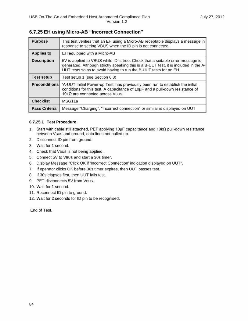
USB On-The-Go and Embedded Host Automated Compliance Plan July 27, 2012 Version 1.2
84
6.7.25 EH using Micro-AB “Incorrect Connection”
Purpose This test verifies that an EH using a Micro-AB receptable displays a message in response to seeing VBUS when the ID pin is not connected.
Applies to EH equipped with a Micro-AB
Description 5V is applied to VBUS while ID is true. Check that a suitable error message is generated. Although strictly speaking this is a B-UUT test, it is included in the A-UUT tests so as to avoid having to run the B-UUT tests for an EH.
Test setup Test setup 1 (see Section 6.3)
Preconditions ‘A-UUT Initial Power-up Test’ has previously been run to establish the initial conditions for this test. A capacitance of 10µF and a pull-down resistance of 10kΩ are connected across VBUS.
Checklist MSG11a
Pass Criteria Message “Charging”, "Incorrect connection" or similar is displayed on UUT
6.7.25.1 Test Procedure
1. Start with cable still attached, PET applying 10µF capacitance and 10kΩ pull-down resistance between VBUS and ground, data lines not pulled up.
2. Disconnect ID pin from ground.
3. Wait for 1 second.
4. Check that VBUS is not being applied.
5. Connect 5V to VBUS and start a 30s timer.
6. Display Message "Click OK if 'Incorrect Connection' indication displayed on UUT".
7. If operator clicks OK before 30s timer expires, then UUT passes test.
8. If 30s elapses first, then UUT fails test.
9. PET disconnects 5V from VBUS.
10. Wait for 1 second.
11. Reconnect ID pin to ground.
12. Wait for 2 seconds for ID pin to be recognised.
End of Test.

USB On-The-Go and Embedded Host Automated Compliance Plan July 27, 2012 Version 1.2
85
6.8 B-UUT Tests
The electrical tests in this section test only a partial list of all the possible electrical parameters. The tests should not be considered as a full validation test plan. It is the responsibility of the manufacturer of a device to verify compliance of all relevant electrical parameters specified in [USB2.0], [USBCables2.0], [USB 3.0] and [USBOTG&EHv2.0].
6.8.1 B-UUT Initial Power-up Test
Purpose To ensure that the OTG B-device or Peripheral-only B-device has been powered up and is ready for the subsequent tests. All following B-device tests assume that this test has been run first.
In the case of an ADP capable device, this test also confirms functional startup sequence.
Applies to EH B-port, OTG B-device, Peripheral-only B-device
Description This test will confirm that the correct cable has been attached, and arrange for the test operator to switch the UUT on.
In the case of an ADP capable device, it will first get the UUT switched off. It will also confirm the commencement of ADP probing.
Test Setup Test setup 1 or 2 (see Section 6.3)
Preconditions None
Checklist ADP13
6.8.1.1 Test Procedure
6.8.1.1.1 Part 1 – Common to All B-UUT Types
1. The user enters into the PET:
Whether the UUT is capable of ADP.
The test sequence followed depends on the UUT type:
OTG B-device or peripheral-only B-device capable of ADP.
OTG B-device or peripheral-only B-device not capable of ADP.
6.8.1.1.2 Part 2 – For OTGB-device or peripheral-only B-device UUT capable of ADP
2. Operator: Ensure UUT attached using Special Test Cable A (Test Setup 1 Section 6.3.1 for an OTG B-device, Test Setup 3 Section 6.3.3 for a Peripheral-only B-device/EH B-port) or, where the device does not have a Micro-AB or Micro-B receptacle, a suitable alternative.
3. UUT is either powered or is not powered. PET is not applying VBUS, and not applying capacitance between VBUS and ground, ID pin is not connected to ground.
4. Operator: Turn UUT off, if not already off.
5. Operator: Turn UUT on.
6. Check that UUT performs an ADP probe within TPWRUP_RDY (30s or as specified by vendor).
7. To check probe, check that VBUS goes below 0.3V and then rises above 0.5V within 10ms.
8. After the first probe check that either a further probe (or probes) is performed, or that D+ goes high. Wait here till D+ goes high or TPWRUP_RDY times out.
9. Check that D+ stays high for at least 5ms.

USB On-The-Go and Embedded Host Automated Compliance Plan July 27, 2012 Version 1.2
86
10. Check that D+ goes low within 10ms of start of pulse.
11. Check ADP probe is not performed for TB_SRP_FAIL min (5s) after start of D+ (SRP) pulse.
12. Check that ADP probe is performed within TB_SRP_FAIL max plus TB_ADP_PRB max (6.0 + 2.6 = 8.6s) after start of D+ (SRP) pulse.
13. Now ready for any other B-UUT test.
6.8.1.1.3 Part 2 – For OTGB-device or Peripheral-only B-device UUT not capable of ADP
2. Operator: Ensure UUT attached using Special Test Cable A ((Test Setup 1 Section 6.3.1 for an OTG B-device, Test Setup 3 Section 6.3.3 for a Peripheral-only B-device/EH B-port) or, where the device does not have a Micro-AB or Micro-B receptacle, a suitable alternative.
3. UUT is either powered or is not powered. PET is not applying VBUS, and not applying capacitance between VBUS and ground, ID pin is not connected to ground.
4. Operator: Turn UUT on, if not already on.
5. PET applies CADP_VBUS max (6.5μF) and a pull-down resistor of ROTG_VBUS min (10kΩ) to VBUS and turns on VBUS.
6. Check that D+ goes high within TPWRUP_RDY (30s).
7. Turn off VBUS and disconnect capacitance and pull-down resistance from VBUS.
8. Wait 5s to allow disconnection to be detected.
9. Now ready for any other B-UUT test.
6.8.1.1.4 Following Tests
From now on all test sequences must start and finish with the PET holding VBUS off, and no capacitance or pull-down resistance connected to VBUS. This allows the tests to be performed in any sequence. As the tests are all on B-UUTs, the ID pin is not connected to ground in any test (except as appropriate in state transition tests).

USB On-The-Go and Embedded Host Automated Compliance Plan July 27, 2012 Version 1.2
87
6.8.2 B-UUT VBUS Voltage and Current Measurements
Purpose To verify VB_VBUS min and max, IB_UNCFG and the declared value of bMaxPower.
Applies to EH B-port, OTG B-device, Peripheral-only B-device
Description Test measures the unconfigured and configured current at VB_VBUS min and VB_VBUS max. It also tests to ensure that the configured current is less than bMaxPower(part of the bmAttributes field of the Standard Configuration Descriptor as defined in [USB2.0] or [USB 3.0]).
Test Setup Test setup 1 or 2 (see Section 6.3)
Preconditions ‘B-UUT Initial Power-up Test’ has previously been run to establish the initial conditions for this test.
It is expected that the value of bMaxPower is known from [USBOTG&EHChecklist].
Checklist E11, E12, M5, ST4
6.8.2.1 Test procedure
1. The user enters the value for bMaxPower into the PET, which can be from 0mA to 500mA.
2. Cable is already attached with the B-device powered up. The PET is not applying VBUS, and not applying capacitance or pull-down resistance between VBUS and ground.
3. Check that UUT is not sourcing VBUS.
4. PET applies CADP_VBUS max (6.5μF) and a pull-down resistor of ROTG_VBUS min (10kΩ) to VBUS and turns on VBUS to VB_VBUS min (4.0V) (this is also VOTG_SESS_VLD max), plus an allowance for special cable resistance at a current of bMaxPower declared by the vendor.
5. Check that D+ goes high within 5s. We expect it to connect within TB_SVLD_BCON (1s).
6. Wait 100ms then apply a bus reset to the B-UUT.
7. Check current drawn <= IB_UNCFG (2.5mA) averaged over 1s (TAVG_VBUS).
8. Enumerate, checking for valid responses, check that the declared bMaxPower matches that specified on checklist. SetConfiguration(1).
9. Check VBUS current <= bMaxPower.
10. Change VBUS voltage to VB_VBUS max (6.0V).
11. Wait TA_BCON_LDB (100ms) then issue a bus reset to the B-UUT.
12. Check IB_UNCFG<= 2.5mA.
13. Enumerate, checking for valid responses, then SetConfiguration(1).
14. Check VBUS current <= bMaxPower.
15. Turn off VBUS and disconnect capacitance and pull-down resistance from VBUS.
16. Wait 5s to allow disconnection to be detected.
17. PET applies CADP_VBUS max (6.5μF) and a pull-down resistor of ROTG_VBUS min (10kΩ) to VBUS and turns on VBUS to slightly less than VOTG_SESS_VLD min (0.8V minus .02V = 0.78V).
18. Check that neither D+ nor D- goes high within the next TB_SVLD_BCON max (1s). If D+ does goes high (owing to ADP interpreting VBUS as a capacitance change and performing SRP), then check that it goes off within 10ms.
19. Turn off VBUS and disconnect capacitance and pull-down resistance from VBUS.
20. Wait 5s to allow disconnection to be detected.
End of test.

USB On-The-Go and Embedded Host Automated Compliance Plan July 27, 2012 Version 1.2
88
6.8.3 B-UUT Bypass Capacitance
Purpose To verify OTG B-device , EH B-port or peripheral-only B-device VBUS bypass capacitance (CRPB and/or CADP_VBUS)
Applies to EH B-port, OTG B-device, Peripheral-only B-device
Description Uses a technique similar to ADP to measure the B-UUT bypass capacitance.
Test Setup Test setup 1 or 2 (see Section 6.3)
Preconditions ‘B-UUT Initial Power-up Test’ has previously been run to establish the initial conditions for this test.
Checklist E14, ADP19, M5, ST4
6.8.3.1 Test procedure
1. Cable is already attached with the B-device powered up. The PET is not applying VBUS, and not applying capacitance or pull-down resistance between VBUS and ground.
2. Check that UUT is not sourcing VBUS.
3. PET applies CADP_VBUS max (6.5μF) and a pull-down resistor of ROTG_VBUS min (10kΩ) to VBUSand turns on VBUS to 5V.
4. Check that D+ goes high within 5s. We expect it to connect within TB_SVLD_BCON (1s).
5. Wait 100ms then issue a bus reset to the B-UUT.
6. Enumerate, checking for valid responses, check that the declared bMaxPower matches that specified on checklist. SetConfiguration(1).
7. Turn off VBUS and disconnect capacitance from VBUS.
8. Wait 1s for VBUS to decay.
9. Disconnect pull-down resistance from VBUS.
Use ADP circuit to evaluate capacitance using rise time. Note: The UUT should not perform any ADP probes within TB_ADP_DETACH min (3s) of VBUS going off, and should hold off doing any while the PET carries out simulated ADP probes. A check after the PET test ensures that this is the case, confirming that the PET measurements are valid.
10. If the B-UUT is ADP capable, check the B-UUT’s capacitance is greater than or equal to CADP_VBUS min (1μF), and less than or equal to CADP_VBUS max (6.5μF). If the B-UUT is not ADP capable, check that the capacitance is greater than or equal to CRPB min (1μF), and less than or equal to CRPB max (10μF).
11. Check that no ADP probe occurs within a TB_ADP_DETACH min (3s) of the last simulated ADP probe from the PET.
12. Wait 2s to allow disconnection to be detected.
End of Test.

USB On-The-Go and Embedded Host Automated Compliance Plan July 27, 2012 Version 1.2
89
6.8.4 B-UUT SRP
Purpose This test will check that the B-device generates SRP requests, after a session.
Applies to EH B-ports, OTG B-devices, Peripheral-only B-devices
Description Uses SetFeature(otg_srp_reqd) to trigger the B-UUT to perform SRP. Verifies that all SRP related parameters are within limits.
Test Setup Test setup 1 or 2 (see Section 6.3)
Preconditions ‘B-UUT Initial Power-up Test’ has previously been run to establish the initial conditions for this test.
Checklist DF1-4, M5, SRP9, SRP10, SRP11, SRP12, T9
6.8.4.1 Test Procedure
1. Cable is already attached with the B-device powered up. The PET is not applying VBUS, and not applying capacitance or pull-down resistance between VBUS and ground.
2. Check that UUT is not sourcing VBUS.
3. PET applies a pull-down resistor of ROTG_VBUS min (10kΩ) to VBUS and turns on VBUS to 5V.
4. Check that D+ goes high within 5s. We expect it to connect within TB_SVLD_BCON (1s).
5. Wait TA_BCON_LDB min (100ms) then issue a bus reset to the B-UUT.
6. Enumerate, checking:
a. Valid response to GetStatus(OTG) in default, addressed and configured states.
b. Valid response to GetDescriptor(Device).
c. Valid response to GetDescriptor(Configuration).
d. OTG descriptor in configuration descriptor has valid fields.
e. OTG descriptor in configuration descriptor declares SRP capability.
f. Valid response to GetDescriptor(String) for declared strings.
g. Valid response to GetDescriptor(OTG).
h. Separate OTG descriptor has valid fields.
i. Separate OTG descriptor declares SRP capability.
7. SetConfiguration(1).
8. SetFeature(otg_srp_reqd). This test mode feature bit requires the UUT to perform an SRP
request within TTST_SRP (5s) of VBUS going off.
9. Wait 1s.
10. Disconnect VBUS pull-down resistor, then turn off VBUS.
11. Check that VBUS goes below VOTG_VBUS_LKG max (0.7V), and that the fall in VBUS from VOTG_SESS_VLD max (4V) to VOTG_VBUS_LKG (0.7V) occurs within TSSEND_LKG (1s).
Note: The fall time is now governed by the B-UUT using its own pull-down resistor to discharge its own capacitance, as the PET has disconnected its pull-down resistor.
12. When VBUS is at 0.7V, check that SE0 is presented on data bus. Note time when it is.
13. Check that D+ is not asserted within TB_SE0_SRP (1s) of this time, or within TB_SSEND_SRP (1.5s) of VBUS having gone below VOTG_SESS_VLD max (4V).
14. Check that D+ is asserted within TTST_SRP (5s) of VBUS going below VOTG_SESS_VLD min (0.8V).
[This is a testability requirement initiated by otg_srp_reqd].
15. Check that D+ remains high for TB_DATA_PLS (5 to 10ms) (Pass 1 only).

USB On-The-Go and Embedded Host Automated Compliance Plan July 27, 2012 Version 1.2
90
16. Depending whether this is first or second pass through test PET applies a pull-down resistor of ROTG_VBUS min (10kΩ) to VBUS and turns on VBUS to 5V:
a. slightly less than TB_SRP_FAIL max (5s minus 0.1s = 4.9s) after start of D+ pulse.
b. immediately after start of D+ pulse.
17. Check that D+ goes high within TB_SVLD_BCON (1s) of VBUS reaching VOTG_SESS_VLD max.
18. Issue a bus reset, and enumerate the B-UUT. Check normal response.
19. Turn off VBUS and disconnect the pull-down resistance from VBUS.
20. Wait 5s to allow disconnection to be detected.
21. Repeat steps 1-20 using alternative timing in step 16.
End of Test.

USB On-The-Go and Embedded Host Automated Compliance Plan July 27, 2012 Version 1.2
91
6.8.5 B-UUT HNP
Purpose This test will check that the B-device generates an HNP request, assumes the host role, and hands back control after a session.
Applies to OTG B-devices
Description Uses SetFeature(‘otg_hnp_reqd) to trigger an HNP role transfer. Verifies that all HNP related parameters are within limits.
Test Setup Test setup 1 or 2 (see Section 6.3)
Preconditions ‘B-UUT Initial Power-up Test’ has previously been run to establish the initial conditions for this test.
Checklist DF1, DF2, DF15, DF17-19, DF22, DF23, HNP12-13, M5, ST4, T17
6.8.5.1 Test Procedure
1. Cable is already attached with the B-device powered up. The PET is not applying VBUS, and not applying capacitance or pull-down resistance between VBUS and ground.
2. Check that UUT is not sourcing VBUS.
3. PET applies CADP_VBUS max (6.5μF) and a pull-down resistor of ROTG_VBUS min (10kΩ) to VBUS
and turns on VBUS to 5V.
4. Check that D+ goes high within 5s. We expect it to connect within TB_SVLD_BCON (1s).
5. Wait 100ms then issue a bus reset to the B-UUT.
6. Enumerate at speed depending on pass number (first two passes at Full Speed, last two passes at High Speed), checking:
a. Valid response to GetStatus(OTG) in default and addressed states.
b. Valid response to GetDescriptor(Device).
c. Valid response to GetDescriptor(Configuration).
d. OTG descriptor in configuration descriptor has valid fields.
e. OTG descriptor in configuration descriptor declares HNP and SRP capability.
f. Valid response to GetDescriptor(String) for declared strings.
g. Valid response to GetDescriptor(OTG).
h. Separate OTG descriptor has valid fields.
i. Separate OTG descriptor declares HNP and SRP capability.
7. SetConfiguration(1).
8. GetStatus(OTG) Check valid response.
9. SetFeature(‘otg_hnp_reqd). Check valid response. This test mode feature bit requires the
UUT to set its Host Request Flag and to perform an HNP request within TTST_HNP (5s).
10. Wait 1s.
11. GetStatus(OTG). Check valid response. Check that Host Request Flag is set.
12. SetFeature(b_hnp_enable). Check valid response.
13. Attempt to ClearFeature(b_hnp_enable). Check valid STALL response.
14. SetFeature(b_hnp_enable). Check valid ACK response.
15. Wait 1s.
16. Stop sending SOFs.
17. If HS check when D+ goes high is within TWTREV (3 to 3.125ms). Allow margin for D+ rise time. If FS skip this check.

USB On-The-Go and Embedded Host Automated Compliance Plan July 27, 2012 Version 1.2
92
18. Check that B-device under test turns off D+ pull-up within TB_AIDL_BDIS max (150ms) of start of idle, but more than TB_FS_BDIS min (1ms). This also tests TB_FS_BDIS max.
19. Depending on which pass of the test:
a. Wait for a notional very small value of TA_BDIS_ACON (1ms) from D+ going low [pass 1 and 3].
b. Wait for slightly less than TA_BDIS_ACON max (150ms minus 1ms = 149ms) from D+ going low. [pass 2 and 4].
20. Turn on D+.
21. Check that we see start of a bus reset (SE0) within TB_ACON_BSE0 (150ms) of D+ going high.
22. Allow PET to be enumerated by B-device under test (the PET identifying itself as PID=0x1A0A VID=0x0200). Even if the UUT does not support HNP Polling, the PET sets its HNP support bit. Check that enumeration was successful. If HNP polled, respond with Host Request Flag cleared.
23. Check that we are suspended within TTST_SUSP (100ms) of the SetConfiguration(0) request. (if we are in HS this involves us in reverting to full speed).
24. Depending on which pass of the test:
a. Wait for TA_BIDL_ADIS min (155ms), checking that D+ remains high (and D- low). [primary timing].
b. Wait for slightly less than TA_BIDL_ADIS max (200ms minus 1ms = 199ms), checking that D+ remains high (and D- low). [alternative timing].
25. Remove D+ pull-up.
26. Wait TLDIS_DSCHG min (25µs).
27. Check that D+ is pulled up by UUT within TTST_HNPEND(5s).
28. Apply a bus reset (SE0), and check that we can enumerate the UUT successfully.
29. Suspend UUT.
30. Turn off VBUS and disconnect capacitance and pull-down resistance from VBUS.
31. Wait 5s to allow disconnection to be detected.
32. Repeat steps 1-30 with alternative timings in steps 18 and 23.
33. Repeat steps 1-30 at High Speed with primary timings in steps 18 and 23.
34. Repeat steps 1-30 at High Speed with alternative timings in steps 18 and 23.
End of Test.

USB On-The-Go and Embedded Host Automated Compliance Plan July 27, 2012 Version 1.2
93
6.8.6 B-UUT ADP
Purpose This test will check that the B-device performs ADP probing and sensing.
Applies to ADP-capable: EH B-ports, OTG B-devices, and Peripheral-only B-devices
Description Exercises the B-UUT in order to verify all ADP-related parameters.
Test Setup Test setup 1 or 2 (see Section 6.3)
Preconditions ‘B-UUT Initial Power-up Test’ has previously been run to establish the initial conditions for this test.
Checklist ADP7-10, ADP12, ADP14, ADP22-25, ADP27-28
6.8.6.1 Test Procedure
1. Cable is already attached with the B-device powered up. The PET is not applying VBUS, and not applying capacitance or pull-down resistance between VBUS and ground. The B-UUT is assumed to be performing ADP probing.
2. Examine the next 11 ADP probes, as follows in steps 3-5, collecting data for validation.
3. Check VBUS goes to VADP_DSCHG (0.15V) or below.
4. Detect VBUS rising through 0.25V and then through 0.5V, record time in between, and also record point in time it passes 0.5V. This gives an estimate of the size of TADP_RISE.
5. Check that VBUS reaches at least VADP_PRB min (0.6V) and check that it does not exceed VADP_PRB max (0.75V).
6. Validate each of the 10 periods TB_ADP_PRB (1.9 – 2.6s) or (0.85 – 1.3s), and check that the cycle to cycle jitter TADP_PRB_JTR (5%) is within limits.
7. On first test pass, connect CADP_VBUS max (6.5µF) across VBUS. On second test pass, connect CADP_THR max (900nF) across VBUS. Ensure that this is connected between probes. (This should cause PET to be detected by next ADP probe.)
8. Check that VBUS goes below VADP_DSCHG (0.15V) within 3s.
9. Detect VBUS rising through 0.25V and then through 0.5V, record time in between.
10. On the first test pass, from the previous and the new values of rise time we can estimate IADP_SRC (1.1 - 1.65mA). Check that the difference in ramp time lies between 885µs and 1626µs. On second test pass, just report times.
11. Connect pull-down resistor of ROTG_VBUS min (10kΩ) to VBUS.
12. Check that D+ goes high within TB_ADP_PRB_SRP max (5s). This is the start of an SRP pulse.
13. Check that D+ stays high for at least TB_DATA_PLS min (5ms).
14. Check that D+ goes low within TB_DATA_PLS max (10ms) of start of pulse.
15. Turn on VBUS.
16. On connect, issue bus reset, and enumerate at Full Speed, checking:
a. Valid response to GetDescriptor(Device).
b. Valid response to GetDescriptor(Configuration).
c. OTG descriptor in configuration descriptor has valid fields.
d. OTG descriptor in configuration descriptor declares ADP and SRP capability.
e. Valid response to GetDescriptor(String) for declared strings.
f. Valid response to GetDescriptor(OTG).
g. Separate OTG descriptor has valid fields.
h. Separate OTG descriptor declares ADP and SRP capability.

USB On-The-Go and Embedded Host Automated Compliance Plan July 27, 2012 Version 1.2
94
i. Do not enable HNP.
17. SetConfiguration(1).
18. Suspend, then end session (VBUS off), and disconnect capacitance and pull-down resistance from VBUS.
19. Check that during the next 2.9s (TB_ADP_DETACH min minus 0.1s) the UUT does not perform any ADP probing.
Note: The PET is behaving out of spec here in order to measure TB_ADP_DETACH.
20. Do ADP probe.
21. Check that during the next TB_ADP_DETACH min (3s) the UUT does not perform any ADP probing.
22. Check that the UUT does a probe within TB_ADP_DETACH max (3.4s) plus TB_SNSEND_PRB max (100ms), a total of 3.5s, of last probe from PET.
Note: This demonstrated that the ADP sensing is working.
23. Disconnect.
24. Wait for 10s, ignoring any SRP pulses.
25. Repeat steps 2-24 using capacitance value of CADP_THR max (900nF) in step 7.
26. Connect (less than) CADP_THR min (150nF) across VBUS. Ensure that this is connected between probes. (This should not cause PET to be detected by next ADP probe).
27. Wait for 2 ADP probes, checking that D+ does not rise.
28. Disconnect capacitance. Ensure that this is disconnected between probes.
29. Wait for 2 ADP probes, checking that D+ does not rise.
30. Connect CADP_VBUS max (6.5μF) across VBUS.
31. Monitor resulting SRP pulse. Do not respond.
32. Check that ADP probe occurs within TB_ADP_PRB max (2.6s).
33. Disconnect capacitor.
34. Wait 10s, ignoring any SRP pulses.
End of Test.

USB On-The-Go and Embedded Host Automated Compliance Plan July 27, 2012 Version 1.2
95
6.8.7 B-UUT Leakage
Purpose This test will measure IVBUS_LKG_SRC max (70µA)
Applies to EH B-ports, OTG B-devices, Peripheral-only B-devices
Description This test makes use of the ADP sense period to check the values of IVBUS_LKG_SRC and ROTG_VBUS.
Test Setup Test setup 1 or 2 (see Section 6.3)
Preconditions ‘B-UUT Initial Power-up Test’ has previously been run to establish the initial conditions for this test.
Checklist E10, ADP18, M5, ST4
6.8.7.1 Test Procedure
1. Cable is already attached with the B-device powered up. The PET is not applying VBUS, and not applying capacitance or pull-down resistance between VBUS and ground. The B-UUT may be performing ADP probing.
2. Check that UUT is not sourcing VBUS.
3. Turn VBUS on to VB_VBUS nom (5V) and simultaneously connect CRPB min (1μF) across VBUS.
4. Check that D+ goes high within TB_SVLD_BCON (1s) of VBUS reaching VOTG_SESS_VLD max (4.0V).
5. Wait TB_BCON_LDB (100ms) then issue a bus reset to the UUT.
6. Enumerate UUT, and SetConfiguration(1).
7. Switch off VBUS and remove VBUS capacitance, and apply 2kΩ pull-down resistance. We now have 3s before ADP is allowed from UUT.
8. Wait 1s.
9. Check that voltage on VBUS is below 140mV. This confirms that IVBUS_LKG_SRC is no more than 70µA.
10. Disconnect 2kΩpull-down resistor.
11. Connect 2k2Ω pull-up resistor, sourced from 0.8V, to VBUS.
12. Wait 1s.
13. Check that voltage on VBUS is greater than or equal to 0.656V. This proves that ROTG_VBUS is greater than or equal to 10kΩ.
14. Disconnect 2k2Ω pull-up resistor.
15. Wait 10s while ignoring any SRP pulse.
End of Test.

USB On-The-Go and Embedded Host Automated Compliance Plan July 27, 2012 Version 1.2
96
6.8.8 B-OTG, Capable of ADP/HNP/SRP, State Transition Test
Purpose This test verifies the UUT follows the correct transitions in the specified state diagrams.
Applies to OTG B-devices, capable of ADP, HNP and SRP.
Description PET performs the necessary actions to force the UUT between each state transition, to ensure correct operation.
Test Setup Test setup 1 or 2 (see Section 6.3)
Preconditions ‘B-UUT Initial Power-up Test’ has previously been run to establish the initial conditions for this test.
Checklist ADP15, ST4
6.8.8.1 Test Procedure
START ->b_idle. (This was done in Power-Up Test).
First perform following test at Full Speed.
1. No capacitance or pull-down resistance connected to VBUS, ID pin not connected.
2. PET connects CADP_VBUS min (1μF) capacitor, and a pull-down resistor of ROTG_VBUS min (10kΩ) from VBUS to ground.
3. Wait 8s (ignoring SRP pulse resulting from capacitance change).
b_idle ->b_peripheral resulting from b_sess_vld.
4. PET turns on VBUS.
5. Check that UUT connects using D+ within TB_SVLD_BCON (1s).
b_peripheral ->b_idle resulting from b_sess_vld/.
6. PET turns off VBUS.
7. Check that UUT disconnects D+ within TSSEND_LKG max (1s).
b_idle ->b_peripheral resulting from b_sess_vld.
8. PET turns on VBUS.
9. Check that UUT connects using D+ within TB_SVLD_BCON (1s).
b_peripheral ->b_idle ->a_idle resulting from id/.
10. PET turns off VBUS (speeding up the fall time by the use of an additional 2kΩ pull-down resistor which is then disconnected), and then connects ID pin to ground.
11. Check that UUT disconnects D+ within 100ms (D+ should not remain on after VBUS is off).
12. Check that UUT performs an ADP probe within 2s.
USB On-The-Go and Embedded Host Automated Compliance Plan July 27, 2012 Version 1.2
97
a_idle ->b_idle resulting from id.
13. PET disconnects ID pin from ground.
14. Check that an ADP probe is performed within 4s.
Note: This allows the UUT to first perform ADP sensing if designed to do so under these conditions, or to continue with ADP probing but at the B-device rate.
15. Check that the next ADP probe is performed TB_ADP_PRB (1.9s to 2.6s OR 0.95s to 1.3s) later.
b_idle ->b_peripheral resulting from b_sess_vld.
16. PET turns on VBUS.
17. Check that UUT connects using D+ within TB_SVLD_BCON (1s).
18. PET issues a bus reset, and enumerates the UUT.
b_peripheral ->b_wait_acon resulting from a_bus_suspend & b_bus_reqd & b_hnp_en.
19. PET performs SetFeature(‘otg_hnp_reqd).
20. PET checks that Host Request Flag is set.
21. PET performs SetFeature(b_hnp_enable).
22. PET suspends UUT.
23. Check that D+ goes low within 150ms.
b_wait_acon ->b_host resulting from a_conn.
24. PET connects D+.
25. Check that UUT resets PET within TB_ACON_BSE0 (150ms).
26. Check that UUT enumerates PET (up to setting configuration 1) within TTST_CONFIG (30s). PET declares itself as test device (VID=0x1A0A, PID=0x0200). If HNP polled, it responds with Host Request Flag set.
b_host ->b_peripheral resulting from b_bus_req/.
27. Check that PET is suspended within TTST_SUSP (100ms) of the SetConfiguration(0) request.
28. Wait TA_BIDL_ADIS min (155ms).
29. PET disconnects D+.
30. Wait TLDIS_DSCHG (25µs)
31. Check that D+ is pulled up by UUT within TTST_HNPEND (5s).
32. PET issues a bus reset, and enumerates the UUT.
(Repeating now with different TA_BIDL_ADIS).
b_peripheral ->b_wait_acon resulting from a_bus_suspend.
33. PET performs SetFeature(‘otg_hnp_reqd).
34. PET checks that Host Request Flag is set.
35. PET performs SetFeature(b_hnp_enable).
36. PET suspends UUT.

USB On-The-Go and Embedded Host Automated Compliance Plan July 27, 2012 Version 1.2
98
37. Check that D+ goes low within 150ms.
b_wait_acon ->b_host resulting from a_conn.
38. PET connects D+.
39. Check that UUT issues a bus reset within TB_ACON_BSE0 (150ms).
40. Check that UUT enumerates PET (up to setting configuration 1) within TTST_CONFIG (30s). PET declares itself as test device (VID=0x1A0A, PID=0x0200). If HNP polled, it responds with Host Request Flag set.
b_host ->b_peripheral resulting from b_bus_req/.
41. Check that PET is suspended within TTST_SUSP (100ms) of the SetConfiguration(0) request.
42. Wait slightly less than TA_BIDL_ADIS max (i.e. 199ms).
43. PET disconnects D+.
44. Wait TLDIS_DSCHG (25µs)
45. Check that D+ is pulled up by UUT within TTST_HNPEND (5s).
46. PET issues a bus reset, and enumerates the UUT.
b_peripheral ->b_wait_acon resulting from a_bus_suspend & b_bus_reqd & b_hnp_en.
47. PET performs SetFeature(‘otg_hnp_reqd).
48. PET checks that Host Request Flag is set.
49. PET performs SetFeature(b_hnp_enable).
50. PET suspends UUT.
51. Check that D+ goes low within 150ms.
b_wait_acon ->b_host resulting from a_conn.
52. PET connects D+.
53. Check that UUT issues a bus reset within TB_ACON_BSE0 (150ms).
b_host ->b_peripheral resulting from a_conn/.
54. PET disconnects D+.
55. Wait TLDIS_DSCHG (25µs).
56. Check that D+ is pulled up by UUT within TTST_HNPEND (5s).
57. PET issues a bus reset, and enumerates the UUT.
b_peripheral ->b_wait_acon resulting from a_bus_suspend.
58. PET performs SetFeature(‘otg_hnp_reqd).
59. PET checks that Host Request Flag is set.
60. PET performs SetFeature(b_hnp_enable).
61. PET suspends UUT.
62. Check that D+ goes low within 150ms.

USB On-The-Go and Embedded Host Automated Compliance Plan July 27, 2012 Version 1.2
99
b_wait_acon ->b_idle resulting from b_sess_vld/.
63. PET turns off VBUS.
64. Check that UUT performs ADP probe within 4s.
b_idle ->b_peripheral resulting from b_sess_vld.
65. PET turns on VBUS
66. Check that UUT connects using D+ within TB_SVLD_BCON (1s).
67. PET issues a bus reset, and enumerates the UUT. PET uses SetFeature(otg_srp_reqd).
b_peripheral ->b_idle ->b_srp_init resulting from b_sess_vld/ and b_bus_reqd & b_ssend_srp & b_se0_srp.
68. PET turns off VBUS.
69. Check that UUT disconnects D+ within TSSEND_LKG max (1s).
70. Check that UUT performs SRP within TTST_SRP max (5s).
b_srp_init ->b_idle resulting from b_srp_done.
71. Check that UUT performs ADP probe within TB_SRP_FAIL max (6s) plus TB_ADP_PRB max (2.6s) plus small margin (total 9s).
b_idle ->b_srp_init resulting from adp_change & b_ssend_srp & b_se0_srp.
72. PET changes VBUS capacitance to CADP_VBUS max (6.5μF).
73. Check that UUT performs ADP probe within 2s.
74. Check that UUT performs SRP pulse within TB_ADP_PRB_SRP max (5s).
b_srp_init ->b_idle resulting from b_srp_done.
75. Check that UUT performs ADP probe within TB_SRP_FAIL max (6s) plus TB_ADP_PRB max (2.6s) plus small margin (total 9s).
76. PET disconnects capacitance and pull-down resistance from VBUS.
77. Wait 8s (ignoring SRP pulse).
End of Test.
Repeat test at High Speed.
6.8.8.2 Paths not tested:
Paths resulting from id/ where VBUS is on, because b_sess_vld/ will automatically result in the same transition. Path from b_srp_init to b_idle resulting from id/, because not practical to distinguish from same transition resulting from b_srp_done. Path from b_wait_acon ->b_peripheral resulting from a_bus_resume or b_ase0_brst_tmout because both these transitions involve time periods which are given no maximum value in [USBOTG&EHv2.0].

USB On-The-Go and Embedded Host Automated Compliance Plan July 27, 2012 Version 1.2
100
6.8.9 B-OTG, Capable of HNP and SRP, State Transition Test
Purpose This test verifies the UUT follows the correct transitions in the specified state diagrams.
Applies to OTG B-devices capable of HNP and SRP, but not ADP.
Description PET performs the necessary actions to force the UUT between each state transition, to ensure correct operation.
Test Setup Test setup 1 or 2 (see Section 6.3)
Preconditions ‘B-UUT Initial Power-up Test’ has previously been run to establish the initial conditions for this test.
Checklist ST4
6.8.9.1 Test Procedure
START ->b_idle. (This was done in Power-Up Test).
First perform following test at Full Speed.
1. No capacitance or pull-down resistance connected to VBUS, ID pin not connected.
b_idle ->b_peripheral resulting from b_sess_vld.
2. PET connects CADP_VBUS min (1μF) capacitor, and a pull-down resistor of ROTG_VBUS min (10kΩ) from VBUS to ground, and turns on VBUS
3. Check that UUT connects using D+ within TB_SVLD_BCON (1s).
b_peripheral ->b_idle resulting from b_sess_vld/.
4. PET turns off VBUS.
5. Check that UUT disconnects D+ within TSSEND_LKG max (1s).
b_idle ->b_peripheral resulting from b_sess_vld.
6. PET turns on VBUS
7. Check that UUT connects using D+ within TB_SVLD_BCON (1s).
b_peripheral ->b_idle ->a_idle resulting from id/.
8. PET turns off VBUS, pulling it down using a 2kΩ resistor, and connects ID pin to ground.
9. Check that UUT disconnects D+ within 100ms.
10. Wait 1s.
a_idle ->b_idle resulting from id.
11. PET disconnects ID pin from ground.
12. Wait 1s.

USB On-The-Go and Embedded Host Automated Compliance Plan July 27, 2012 Version 1.2
101
b_idle ->b_peripheral resulting from b_sess_vld.
13. PET turns on VBUS
14. Check that UUT connects using D+ within TB_SVLD_BCON (1s)
15. PET issues a bus reset, and enumerates the UUT.
b_peripheral ->b_wait_acon resulting from a_bus_suspend & b_bus_reqd & b_hnp_en.
16. PET performs SetFeature(‘otg_hnp_reqd).
17. PET checks that Host Request Flag is set.
18. PET performs SetFeature(b_hnp_enable).
19. PET suspends UUT.
20. Check that D+ goes low within TB_AIDL_BDIS (150ms).
b_wait_acon ->b_host resulting from a_conn.
21. PET connects D+
22. Check that UUT issues a bus reset to PET within TB_ACON_BSE0 (150ms).
23. Check that UUT enumerates PET (up to setting configuration 1) within TTST_CONFIG (30s). PET declares itself as test device (VID=0x1A0A, PID=0x0200). If HNP polled, it responds with Host Request Flag set.
b_host ->b_peripheral resulting from b_bus_req/.
24. Check that PET is suspended within TTST_SUSP(100ms) of the SetConfiguration(0) request.
25. Wait TA_BIDL_ADIS min (155ms).
26. PET disconnects D+.
27. Wait TLDIS_DSCHG (25µs)
28. Check that D+ is pulled up by UUT within TTST_HNPEND (5s).
29. PET issues a bus reset, and enumerates the UUT.
(Repeating now with different TA_BIDL_ADIS).
b_peripheral ->b_wait_acon resulting from a_bus_suspend
30. PET performs SetFeature(‘otg_hnp_reqd).
31. PET checks that Host Request Flag is set.
32. PET performs SetFeature(b_hnp_enable).
33. PET suspends UUT.
34. Check that D+ goes low within 150ms.
b_wait_acon ->b_host resulting from a_conn.
35. PET connects D+
36. Check that UUT issues a bus reset within TB_ACON_BSE0 (150ms).

USB On-The-Go and Embedded Host Automated Compliance Plan July 27, 2012 Version 1.2
102
37. Check that UUT enumerates PET (up to setting configuration 1) within TTST_CONFIG (30s). PET declares itself as test device (VID=0x1A0A, PID=0x0200). If HNP polled, it responds with Host Request Flag set.
b_host ->b_peripheral resulting from b_bus_req/.
38. Check that PET is suspended within TTST_SUSP (100ms) of the SetConfiguration(0) request.
39. Wait slightly less than TA_BIDL_ADIS max (i.e. 199ms).
40. PET disconnects D+.
41. Wait TLDIS_DSCHG (25µs).
42. Check that D+ is pulled up by UUT within TTST_HNPEND (5s).
43. PET issues a bus reset, and enumerates the UUT.
b_peripheral ->b_wait_acon resulting from a_bus_suspend & b_bus_reqd & b_hnp_en
44. PET performs SetFeature(‘otg_hnp_reqd).
45. PET checks that Host Request Flag is set.
46. PET performs SetFeature(b_hnp_enable).
47. PET suspends UUT.
48. Check that D+ goes low within TB_AIDL_BDIS (150ms).
b_wait_acon ->b_host resulting from a_conn.
49. PET connects D+
50. Check that UUT issues a bus reset within TB_ACON_BSE0 (150ms).
b_host ->b_peripheral resulting from a_conn/.
51. PET disconnects D+.
52. Wait TLDIS_DSCHG (25µs)
53. Check that D+ is pulled up by UUT within TTST_HNPEND (5s).
54. PET issues a bus reset, and enumerates the UUT.
b_peripheral ->b_wait_acon resulting from a_bus_suspend.
55. PET performs SetFeature(‘otg_hnp_reqd).
56. PET checks that Host Request Flag is set.
57. PET performs SetFeature(b_hnp_enable).
58. PET suspends UUT.
59. Check that D+ goes low within 150ms.
b_wait_acon ->b_idle resulting from b_sess_vld/.
60. PET turns off VBUS.
61. Wait 1s.
b_idle ->b_peripheral resulting from b_sess_vld.

USB On-The-Go and Embedded Host Automated Compliance Plan July 27, 2012 Version 1.2
103
62. PET turns on VBUS.
63. Check that UUT connects using D+ within TB_SVLD_BCON (1s).
64. PET issues a bus reset, and enumerates the UUT. PET uses SetFeature(otg_srp_reqd).
b_peripheral ->b_idle ->b_srp_init resulting from b_sess_vld/ and b_bus_reqd & b_ssend_srp & b_se0_srp.
65. PET turns off VBUS and disconnects capacitance and pull-down resistance from VBUS.
66. Check that UUT disconnects D+ within TSSEND_LKG max (1s).
67. Check that UUT performs SRP within TTST_SRP max (5s).
b_srp_init ->b_idle resulting from b_srp_done.
68. Wait 6s.
End of Test.
Repeat test at High Speed.
6.8.9.2 Paths not tested:
Paths resulting from id/ where VBUS is on, because b_sess_vld/ will automatically result in the same transition. Path from b_srp_init to b_idle resulting from id/, because not practical to distinguish from same transition resulting from b_srp_done.

USB On-The-Go and Embedded Host Automated Compliance Plan July 27, 2012 Version 1.2
104
6.8.10 OTG B-device, Capable of ADP and SRP only, State Transition Test
Purpose This test verifies the UUT follows the correct transitions in the specified state diagrams.
Applies to OTG B-devices capable of ADP and SRP, but not HNP.
Description PET performs the necessary actions to force the UUT between each state transition, to ensure correct operation.
Test Setup Test setup 1 or 2 (see Section 6.3)
Preconditions ‘B-UUT Initial Power-up Test’ has previously been run to establish the initial conditions for this test.
Checklist ST4
6.8.10.1 Test Procedure
START ->b_idle. (This was done in Power-Up Test).
First perform following test at Full Speed.
1. No capacitance or pull-down resistance connected to VBUS, ID pin not connected.
2. PET connects CADP_VBUS min (1μF) capacitor, and a pull-down resistor of ROTG_VBUS min (10kΩ) from VBUS to ground.
3. Wait 8s (ignoring SRP pulse resulting from capacitance change).
b_idle ->b_peripheral resulting from b_sess_vld.
4. PET turns on VBUS.
5. Check that UUT connects using D+ within TB_SVLD_BCON (1s).
b_peripheral ->b_idle resulting from b_sess_vld/.
6. PET turns off VBUS.
7. Check that UUT disconnects D+ within TSSEND_LKG max (1s).
b_idle ->b_peripheral resulting from b_sess_vld.
8. PET turns on VBUS.
9. Check that UUT connects using D+ within TB_SVLD_BCON (1s).
b_peripheral ->b_idle ->a_idle resulting from id/.
10. PET turns off VBUS (speeding up the fall time by the use of an additional 2kΩ pull-down resistor which is then disconnected), and then connects ID pin to ground.
11. Check that UUT disconnects D+ within 100ms (D+ should not remain on after VBUS is off).
12. Wait 2 seconds.
Note: We may see either an ADP probe or VBUS on at this point, so don’t do a check.

USB On-The-Go and Embedded Host Automated Compliance Plan July 27, 2012 Version 1.2
105
a_idle ->b_idle resulting from id.
13. PET disconnects ID pin from ground.
14. Check that an ADP probe is performed within 4s.
Note: This allows the UUT to first perform ADP sensing if designed to do so under these conditions, or to continue with ADP probing but at the B-device rate.
15. Check that the next ADP probe is performed TB_ADP_PRB (1.9s to 2.6s OR 0.95s to 1.3s) later.
b_idle ->b_peripheral resulting from b_sess_vld.
16. PET turns on VBUS
17. Check that UUT connects using D+ within TB_SVLD_BCON (1s).
18. PET issues a bus reset, and enumerates the UUT. PET uses SetFeature(otg_srp_reqd).
b_peripheral ->b_idle ->b_srp_init resulting from b_sess_vld/ and b_bus_reqd & b_ssend_srp & b_se0_srp.
19. PET turns off VBUS.
20. Check that UUT disconnects D+ within TSSEND_LKG max (1s).
21. Check that UUT performs SRP within TTST_SRP max (5s).
b_srp_init ->b_idle resulting from b_srp_done.
22. Check that UUT performs ADP probe within TB_SRP_FAIL max (6s) plus TB_ADP_PRB max (2.6s) plus small margin (total 9s).
b_idle ->b_srp_init resulting from adp_change & b_ssend_srp & b_se0_srp.
23. PET changes VBUS capacitance to CADP_VBUS max (6.5μF).
24. Check that UUT performs ADP probe within 2s.
25. Check that UUT performs SRP pulse within TB_ADP_PRB_SRP max (5s).
b_srp_init ->b_idle resulting from b_srp_done.
26. Check that UUT performs ADP probe within TB_SRP_FAIL max (6s) plus TB_ADP_PRB max (2.6s) plus small margin (total 9s).
27. PET disconnects capacitance and pull-down resistance from VBUS.
28. Wait 8s (ignoring SRP pulse).
End of Test.
Repeat test at High Speed.
6.8.10.2 Paths not tested:
Paths resulting from id/ where VBUS is on, because b_sess_vld/ will automatically result in the same transition. Path from b_srp_init to b_idle resulting from id/, because not practical to distinguish from same transition resulting from b_srp_done.

USB On-The-Go and Embedded Host Automated Compliance Plan July 27, 2012 Version 1.2
106
6.8.11 OTG B-device, Capable of SRP only, State Transition Test
Purpose This test verifies the UUT follows the correct transitions in the specified state diagrams.
Applies to OTG B-devices capable of SRP, but not ADP or HNP.
Description PET performs the necessary actions to force the UUT between each state transition, to ensure correct operation.
Test Setup Test setup 1 or 2 (see Section 6.3)
Preconditions ‘B-UUT Initial Power-up Test’ has previously been run to establish the initial conditions for this test.
Checklist ST4
6.8.11.1 Test Procedure
START ->b_idle. (This was done in Power-Up Test).
First perform following test at Full Speed.
1. No capacitance or pull-down resistance connected to VBUS, ID pin not connected.
b_idle ->b_peripheral resulting from b_sess_vld.
2. PET connects CADP_VBUS min (1μF) capacitor, and a pull-down resistor of ROTG_VBUS min (10kΩ) from VBUS to ground, and turns on VBUS
3. Check that UUT connects using D+ within TB_SVLD_BCON (1s).
b_peripheral ->b_idle resulting from b_sess_vld/.
4. PET turns off VBUS.
5. Check that UUT disconnects D+ within TSSEND_LKG max (1s).
b_idle ->b_peripheral resulting from b_sess_vld.
6. PET turns on VBUS
7. Check that UUT connects using D+ within TB_SVLD_BCON (1s).
b_peripheral ->b_idle ->a_idle resulting from id/.
8. PET turns off VBUS, pulling it down using a 2kΩ resistor, and connects ID pin to ground.
9. Check that UUT disconnects D+ within 100ms.
10. Check that VBUS is above VOTG_SESS_VLD max (4V) within TA_VBUS_ATT max (200ms). Check rise time from VOTG_VBUS_LKG to VA_VBUS_AVG_LO does not exceed TA_VBUS_RISE.
11. Wait 1s.
a_idle ->b_idle resulting from id.

USB On-The-Go and Embedded Host Automated Compliance Plan July 27, 2012 Version 1.2
107
12. PET disconnects ID pin from ground.
13. Check that VBUS goes below VOTG_SESS_VLD min (0.8V) within TSSEND_LKG max (1 sec).
14. Wait 1s.
b_idle ->b_peripheral resulting from b_sess_vld.
15. PET turns on VBUS.
16. Check that UUT connects using D+ within TB_SVLD_BCON (1s).
17. PET issues a bus reset, and enumerates the UUT. PET uses SetFeature(otg_srp_reqd).
b_peripheral ->b_idle ->b_srp_init resulting from b_sess_vld/ and b_bus_reqd & b_ssend_srp & b_se0_srp.
18. PET turns off VBUS and disconnects capacitance and pull-down resistance from VBUS.
19. Check that UUT disconnects D+ within TSSEND_LKG max (1s).
20. Check that UUT performs SRP within TTST_SRP max (5s).
b_srp_init ->b_idle resulting from b_srp_done.
21. Wait 6s.
End of Test.
Repeat test at High Speed.
6.8.11.2 Paths not tested:
Paths resulting from id/ where VBUS is on, because b_sess_vld/ will automatically result in the same transition. Path from b_srp_init to b_idle resulting from id/, because not practical to distinguish from same transition resulting from b_srp_done.

USB On-The-Go and Embedded Host Automated Compliance Plan July 27, 2012 Version 1.2
108
6.8.12 OTG B-device, Capable of No Protocol, State Transition Test
Purpose This test verifies the UUT follows the correct transitions in the specified state diagrams.
Applies to OTG B-devices not capable of SRP, ADP or HNP.
Description PET performs the necessary actions to force the UUT between each state transition, to ensure correct operation.
Test Setup Test setup 1 or 2 (see Section 6.3)
Preconditions ‘B-UUT Initial Power-up Test’ has previously been run to establish the initial conditions for this test.
Checklist ST4
6.8.12.1 Test Procedure
START ->b_idle. (This was done in Power-Up Test).
First perform following test at Full Speed.
1. No capacitance or pull-down resistance connected to VBUS, ID pin not connected.
b_idle ->b_peripheral resulting from b_sess_vld.
2. PET connects CADP_VBUS min (1μF) capacitor, and a pull-down resistor of ROTG_VBUS min (10kΩ) from VBUS to ground, and turns on VBUS
3. Check that UUT connects using D+ within TB_SVLD_BCON (1s).
b_peripheral ->b_idle resulting from b_sess_vld/.
4. PET turns off VBUS.
5. Check that UUT disconnects D+ within TSSEND_LKG max (1s).
b_idle ->b_peripheral resulting from b_sess_vld.
6. PET turns on VBUS
7. Check that UUT connects using D+ within TB_SVLD_BCON (1s).
b_peripheral ->b_idle ->a_idle resulting from id/.
8. PET turns off VBUS, pulling it down using a 2kΩ resistor, and connects ID pin to ground.
9. Check that UUT disconnects D+ within 100ms.
10. Check that VBUS is above VOTG_SESS_VLD max (4V) within TA_VBUS_ATT max (200ms). Check rise time from VOTG_VBUS_LKG to VA_VBUS_AVG_LO does not exceed TA_VBUS_RISE.
11. Wait 1s.
a_idle ->b_idle resulting from id.

USB On-The-Go and Embedded Host Automated Compliance Plan July 27, 2012 Version 1.2
109
12. PET disconnects ID pin from ground.
13. Check that VBUS goes below VOTG_SESS_VLD min (0.8V) within TSSEND_LKG max (1 sec).
14. Wait 1s.
b_idle ->b_peripheral resulting from b_sess_vld.
15. PET turns on VBUS.
16. Check that UUT connects using D+ within TB_SVLD_BCON (1s).
17. PET issues a bus reset, and enumerates the UUT.
b_peripheral ->b_idle resulting from b_sess_vld/.
18. PET turns off VBUS and disconnects capacitance and pull-down resistance from VBUS.
19. Check that UUT disconnects D+ within TSSEND_LKG max (1s).
20. Wait 6s.
Repeat test at High Speed.
End of Test.
6.8.12.2 Paths not tested:
Paths resulting from id/ where VBUS is on, because b_sess_vld/ will automatically result in the same transition.

USB On-The-Go and Embedded Host Automated Compliance Plan July 27, 2012 Version 1.2
110
6.8.13 ADP-Capable Peripheral Only B-device State Transition Test
Purpose This test verifies the UUT follows the correct transitions in the specified state diagrams.
Applies to Peripheral Only B-devices capable of ADP and SRP.
Description PET performs the necessary actions to force the UUT between each state transition, to ensure correct operation.
Test Setup Test setup 3 (see Section 6.3.3)
Preconditions ‘B-UUT Initial Power-up Test’ has previously been run to establish the initial conditions for this test.
Checklist ADP15, ST1
6.8.13.1 Test Procedure
START ->bp_idle. (This was done in Power-Up Test). First perform following test at Full Speed.
1. No capacitance or pull-down resistance connected to VBUS, ID pin not connected.
2. PET connects CADP_VBUS min (1μF) capacitor, and a pull-down resistor of ROTG_VBUS min (10kΩ) from VBUS to ground.
3. Wait 8s (ignoring SRP pulse resulting from capacitance change).
bp_idle ->bp_peripheral resulting from b_sess_vld.
4. PET turns on VBUS.
5. Check that UUT connects using D+ within TB_SVLD_BCON (1s)
6. PET issues a bus reset, and enumerates the UUT. PET uses SetFeature(otg_srp_reqd).
bp_peripheral ->bp_idle ->bp_srp_init resulting from b_sess_vld/ and b_bus_reqd & b_ssend_srp & b_se0_srp.
7. PET turns off VBUS.
8. Check that UUT disconnects D+ within TSSEND_LKG max (1s).
9. Check that UUT performs SRP within TTST_SRP max (5s).
bp_srp_init ->bp_idle resulting from b_srp_done. 10. Check that UUT performs ADP probe within TB_SRP_FAIL max (6s) plus TB_ADP_PRB max (2.6s)
plus small margin (total 9s).
bp_idle ->bp_srp_init resulting from adp_change & b_ssend_srp & b_se0_srp.
11. PET changes VBUS capacitance to CADP_VBUS max (6.5μF), ensuring that this occurs in-between probes.
12. Check that UUT performs ADP probe within 2s.
13. Check that UUT performs SRP pulse within TB_ADP_PRB_SRP max (5s).

USB On-The-Go and Embedded Host Automated Compliance Plan July 27, 2012 Version 1.2
111
bp_srp_init ->bp_idle resulting from b_srp_done.
14. Check that UUT performs ADP probe within 2s.
15. PET disconnects capacitance and pull-down resistance from VBUS.
16. Wait 8s (ignoring SRP pulse).
End of Test.
Repeat test at High Speed.
6.8.13.2 Paths not tested:
None.

USB On-The-Go and Embedded Host Automated Compliance Plan July 27, 2012 Version 1.2
112
6.8.14 SRP Only Capable Peripheral Only B-device State Transition Test
Purpose This test verifies the UUT follows the correct transitions in the specified state diagrams.
Applies to Peripheral Only B-devices capable of SRP, but not ADP.
Description PET performs the necessary actions to force the UUT between each state transition, to ensure correct operation.
Test Setup Test setup 3 (see Section 6.3.3)
Preconditions ‘B-UUT Initial Power-up Test’ has previously been run to establish the initial conditions for this test.
Checklist ST1
6.8.14.1 Test Procedure
START ->bp_idle. (This was done in Power-Up Test).
First perform following test at Full Speed.
1. No capacitance or pull-down resistance connected to VBUS.
bp_idle ->bp_peripheral resulting from b_sess_vld.
2. PET connects CADP_VBUS max (6.5μF) capacitor, and a pull-down resistor of ROTG_VBUS min (10kΩ) from VBUS to ground., and turns on VBUS.
3. Check that UUT connects using D+ within TB_SVLD_BCON (1s).
4. PET issues a bus reset, and enumerates the UUT. PET uses SetFeature(otg_srp_reqd).
bp_peripheral ->bp_idle ->bp_srp_init resulting from b_sess_vld/ and b_bus_reqd & b_ssend_srp & b_se0_srp
5. PET turns off VBUS.
6. Check that UUT disconnects D+ within TSSEND_LKG max (1s).
7. Check that UUT performs SRP within TTST_SRP max (5s).
bp_srp_init ->bp_idle resulting from b_srp_done
8. PET disconnects capacitance and pull-down resistance from VBUS.
9. Wait 2s.
End of Test
Repeat test at High Speed.
6.8.14.2 Paths not tested:
None.

USB On-The-Go and Embedded Host Automated Compliance Plan July 27, 2012 Version 1.2
113
6.8.15 Peripheral Only B-device, Capable of No Protocols, State Transition Test
Purpose This test verifies the UUT follows the correct transitions in the specified state diagrams.
Applies to Peripheral Only B-devices capable of neither SRP nor ADP.
Description PET performs the necessary actions to force the UUT between each state transition, to ensure correct operation.
Test Setup Test setup 3 (see Section 6.3.3)
Preconditions ‘B-UUT Initial Power-up Test’ has previously been run to establish the initial conditions for this test.
Checklist ST1
6.8.15.1 Test Procedure
START ->bp_idle. (This was done in Power-Up Test).
First perform following test at Full Speed.
10. No capacitance or pull-down resistance connected to VBUS.
bp_idle ->bp_peripheral resulting from b_sess_vld.
11. PET connects CADP_VBUS max (6.5μF) capacitor, and a pull-down resistor of ROTG_VBUS min (10kΩ) from VBUS to ground., and turns on VBUS.
12. Check that UUT connects using D+ within TB_SVLD_BCON (1s).
13. PET issues a bus reset, and enumerates the UUT.
bp_peripheral ->bp_idle resulting from b_sess_vld/
14. PET turns off VBUS.
15. Check that UUT disconnects D+ within TSSEND_LKG max (1s).
16. PET disconnects capacitance and pull-down resistance from VBUS.
17. Wait 2s.
End of Test
Repeat test at High Speed.
6.8.15.2 Paths not tested:
None.

USB On-The-Go and Embedded Host Automated Compliance Plan July 27, 2012 Version 1.2
114
6.8.16 B-UUT “Device no response” for SRP
Purpose This test verifies that the B-UUT displays an error message when it is unable to start a session using SRP. The B-UUT is attached to a non-responsive A-PET for this test.
Applies to SRP-Capable: EH B-ports, OTG B-devices, Peripheral-only B-devices
Description Uses SetFeature(otg_srp_reqd) to cause the B-UUT to generate an SRP pulse, then fail to respond to the SRP. Check that a suitable error message is generated.
Test Setup Test setup 1 or 2 (see Section 6.3)
Preconditions ‘B-UUT Initial Power-up Test’ has previously been run to establish the initial conditions for this test.
Checklist SRP13, MSG11, M5, ST4
Pass Criteria The test fails if:
The B-UUT does not display a “Device notresponding” or similar type error message between the 5s and 6s messages.
6.8.16.1 Test Procedure
1. Cable is already attached with the B-device powered up. The PET is not applying VBUS, and not applying capacitance or pull-down resistance between VBUS and ground.
2. Check that UUT is not sourcing VBUS.
3. Turn VBUS on (5V), and simultaneously connect CADP_VBUS max (6.5μF), and a pull-down resistor of ROTG_VBUS min (10kΩ) between VBUS and ground.
4. Check that D+ goes high within 5s. We expect it to connect within TB_SVLD_BCON (1s).
5. Wait 100ms then issue a bus reset to the B-UUT.
6. Enumerate, checking:
a. Valid response to GetDescriptor(Device).
b. Valid response to GetDescriptor(Configuration).
c. OTG descriptor in configuration descriptor has valid fields.
d. OTG descriptor in configuration descriptor declares SRP capability.
e. Valid response to GetDescriptor(String) for declared strings.
f. Valid response to GetDescriptor(OTG).
g. Separate OTG descriptor has valid fields.
h. Separate OTG descriptor declares SRP capability
7. SetConfiguration(1).
8. SetFeature(otg_srp_reqd). This test mode feature bit requires the UUT to perform an SRP
request within 5s of VBUS going off.
9. Wait 1s.
10. Turn off VBUS.
11. Check that D+ is not asserted within TB_SE0_SRP (1s) of this time, or within TB_SSEND_SRP (1.5s) of VBUS having gone below VOTG_SESS_VLD max (4V).
12. Check that D+ is asserted within 5s of VBUS going below VOTG_SESS_VLD min (0.8V).
13. Check that D+ remains high for TB_DATA_PLS (5 to 10ms).
14. Do not turn on VBUS.
15. Wait TB_SRP_FAIL max (6s).

USB On-The-Go and Embedded Host Automated Compliance Plan July 27, 2012 Version 1.2
115
16. Display Message "Click OK if 'Device No Response' indication displayed on UUT".
17. If operator clicks OK before 30s elapses since VBUS went on, then UUT passes test.
18. If 30s elapses first, then UUT fails test.
19. Disconnect VBUS capacitance and VBUS pull-down resistor.
20. Wait 2s. to allow disconnection to be recognized.
End of Test.

USB On-The-Go and Embedded Host Automated Compliance Plan July 27, 2012 Version 1.2
116
6.8.17 B-UUT “Unsupported Device”
Purpose This test verifies that the B-UUT displays an unsupported device error message when it becomes host and enumerates the A-PET which is programmed to have an unsupported Vendor and Device ID.
Applies to OTG B-devices capable of HNP in the B-device position
Description UsesSetFeature(otg_hnp_reqd) to force B-UUT to become host. Get enumerated and respond as an unknown device, not supporting HNP. Check that a suitable error message is generated.
Test Setup Test setup 1 or 2 (see Section 6.3)
Preconditions ‘B-UUT Initial Power-up Test’ has previously been run to establish the initial conditions for this test.
Checklist M5, ST4, TP15
Pass Criteria The test fails if:
The B-UUT does not display an “Unsupported device” or similar error message before 30s.
6.8.17.1 Test Procedure
1. Cable is already attached with the B-device powered up. The PET is not applying VBUS, and not applying capacitance or pull-down resistance between VBUS and ground.
2. Check that UUT is not sourcing VBUS.
3. Turn VBUS on (5V), and simultaneously connect CADP_VBUS max (6.5μF), and a pull-down resistor of ROTG_VBUS min (10kΩ) between VBUS and ground.
4. Check that D+ goes high within 5s. We expect it to connect within TB_SVLD_BCON (1s).
5. Wait 100ms then issue a bus reset to the B-UUT.
6. Enumerate at Full Speed, checking valid responses.
7. SetConfiguration(1).
8. GetStatus(OTG) Check valid response.
9. SetFeature(‘otg_hnp_reqd). Check valid response. This test mode feature bit requires the
UUT to perform an HNP request within 5s of VBUS going off.
10. Wait 1s.
11. GetStatus(OTG). Check valid response. Check that Host Request Flag is set.
12. SetFeature(b_hnp_enable). Check valid response.
13. Wait 1s.
14. Stop sending SOFs.
15. Check that B-device under test turns off D+ pull-up within TB_AIDL_BDIS max (150ms) of start of suspend, but more than TB_FS_BDIS min (1ms).
16. Wait 140ms, i.e. TA_BDIS_ACON (150ms) minus a small amount.
17. Connect D+ pull-up.
18. Check that we see start of a bus reset (SE0) within TB_ACON_BSE0 (150ms) of D+ pull-up.
19. Allow PET to be enumerated by B-device under test. The PET responds with a VID / PID combination not on the TPL of the UUT (by default 0x1A0A / 0x0201, but the test operator may select other combinations), and also with the OTG descriptor stating that it does not support
HNP. Check that enumeration was successful. If HNP polled, respond with Host Request Flag cleared.

USB On-The-Go and Embedded Host Automated Compliance Plan July 27, 2012 Version 1.2
117
20. Start 30s timer when Device Descriptor is read.
21. Display Message "Click OK if 'Unsupported Device’ indication displayed on UUT".
22. If operator clicks OK before 30s timer expires, then UUT passes test.
23. If 30s elapses first, then UUT fails test.
24. Wait for 10s.
25. PET disconnects (no capacitance or pull-down resistor on VBUS and no pullup on D+).
26. Wait 2s. to allow disconnection to be recognized.
End of Test.

USB On-The-Go and Embedded Host Automated Compliance Plan July 27, 2012 Version 1.2
118
6.8.18 B-UUT “Device No Response” for HNP
Purpose This test verifies that the B-UUT displays an error message when it starts a session and HNP fails.
Applies to OTG B-devices capable of HNP in the B-device position
Description Uses SetFeature(otg_hnp_reqd) to force B-UUT to become host. Fail to respond as a peripheral. Check that a suitable error message is generated.
Test Setup Test setup 1 or 2 (see Section 6.3)
Preconditions ‘B-UUT Initial Power-up Test’ has previously been run to establish the initial conditions for this test.
Checklist M5, MSG11, SRP13, ST4
Pass Criteria The test fails if:
The B-UUT does not display a “Device no response” or similar type error message before 30s.
6.8.18.1 Test Procedure
1. Cable is already attached with the B-device powered up. The PET is not applying VBUS, and not applying capacitance or pull-down resistance between VBUS and ground.
2. Check that UUT is not sourcing VBUS.
3. Turn VBUS on (5V), and simultaneously connect CADP_VBUS max (6.5μF), and a pull-down resistor of ROTG_VBUS min (10kΩ) between VBUS and ground.
4. Check that D+ goes high within 5s. We expect it to connect within TB_SVLD_BCON (1s).
5. Wait 100ms then issues a bus reset to the B-UUT.
6. Enumerate at Full Speed, checking valid responses.
7. SetConfiguration(1).
8. GetStatus(OTG) Check valid response.
9. SetFeature(‘otg_hnp_reqd). Check valid response. This test mode feature bit requires the
UUT to perform an HNP request within 5s of VBUS going off.
10. Wait 1s.
11. GetStatus(OTG). Check valid response. Check that Host Request Flag is set.
12. SetFeature(b_hnp_enable). Check valid response.
13. Wait 1s.
14. Stop sending SOFs and start timer.
15. Display Message "Click OK if 'Unsupported Device’ indication displayed on UUT".
16. If operator clicks OK before 30s timer expires, then UUT passes test.
17. If 30s elapses first, then UUT fails test.
18. PET disconnects (no capacitance or pull-down resistor on VBUS).
19. Wait 2s. to allow disconnection to be recognized.
End of test.

USB On-The-Go and Embedded Host Automated Compliance Plan July 27, 2012 Version 1.2
119
7 Manual Interoperability Tests
7.1 Introduction
Targeted Hosts are tested for interoperability with peripherals from the device’s own Targeted Peripheral List plus other retail USB products which could be attached to the Targeted Host.
7.1.1 What does “Category” mean?
This is the general type of a specific Targeted Peripheral that an A-UUT has listed on its TPL. Examples of categories are: memory sticks, CDROMs, MTP peripherals, audio headsets, mice, keyboards, etc. The category storage includes USB floppy, USB CDROM, Flash card readers etc. An A-UUT can limit its output the power, based on which Targeted Peripheral is connected. For example if the A-UUT limits its output power to 100mA, based on the power requirements of a particular Targeted Peripheral, it can only additionally support memory sticks that consume no more than 100mA.
7.1.2 What does “Prove Functionality” mean?
Does the A-UUT function in the way that has been defined by the A-UUT vendor which can be functionally less than the user may expect. Proving the functionality of a device can be limited to some very basic operations e.g. A device of the memory stick category can have a single function to read out specific file types and provide no other function.
There should however be some operation which provides value to the end user; it is not sufficient to enumerate the device and show the device as available to the user without providing any further functionality. Where multiple, selected USB modes are provided the A-UUT is expected to follow these requirements in all modes of operation.
7.2 Interoperability Requirements
7.2.1 Targeted Peripheral List
Any OTG device, acting as a host, must work with all the peripherals listed on the device’s Targeted Peripheral List.
The manufacturer of an OTG device is expected to provide a subset of the peripheral(s) from the device’s Targeted Peripheral List for testing. It is required that the OTG device, acting as a host, proves functionality with the peripheral(s) supplied from the device’s Targeted Peripheral List.
The manufacturer is responsible for verifying that the OTG device supports all the peripherals listed on the device’s Target Peripheral List. If an OTG device is found NOT to work with a peripheral on the device’s Targeted Peripheral List, all of the OTG devices on the shelves could be recalled.
7.2.2 Error messages
Silent failures are not allowed and therefore a clear message shall be generated when any sort of error situation occurs.
Where hubs are non-supported a clear “Hub not supported” or similar error message appears and not a generic “not supported” or similar error message.
7.2.3 Hub support
If an A-UUT supports hubs following items shall be taken into account:
- Simultaneous operation of multiple peripherals shall be supported
- Full speed hubs shall be supported

USB On-The-Go and Embedded Host Automated Compliance Plan July 27, 2012 Version 1.2
120
- Where bus powered hubs are supported the potential limitation of 100mA for each port
shall be considered
7.3 Interoperability test definitions
7.3.1 A-UUT Functionality B-device
Purpose Prove the functionality of an OTG A-device or EH
Applies to OTG A-devices and EH’s that perform VID/PID detection of TPL peripherals
Description Test the functionality of the TPL peripherals
Test setup At least one TPL device corresponding to each supported category
Preconditions The A-UUT is powered ON
Use a Micro-A plug to Standard-A Receptacle adapter if the product is an OTG device.
Checklist TPL2-4, TPL7
Pass Criteria Prove the functionality of all TPL B-devices in combination with the A-UUT
7.3.1.1 Test procedure
1. Power ON the A-UUT.
a. If the product is an OTG device with a Micro-AB receptacle then attach a Micro-A
plug to Standard-A Receptacle adapter.
b. If the B-device requires external power, power on the B-device.
2. Attach a B-device taken from the TPL and prove functionality.
3. Detach the B-device and see if the device is disconnected correctly.
4. Attach the B-device and prove functionality.
End of test.
Repeat the above steps for each of the different supported category e.g. if A-UUT supports two
mice, four keyboards, two MSC device than the above test should be performed with these 3 peripherals.

USB On-The-Go and Embedded Host Automated Compliance Plan July 27, 2012 Version 1.2
121
7.3.2 A-UUT Category Functionality B-device
Purpose Prove the category functionality of an OTG A-deviceor EH
Applies to OTG A-devices and EH’s that support a certain category of device
Description Test the functionality of each of the supported categories
Test setup - One B-device of each supported category with 500mA in their descriptor, if not available use a device with highest max power descriptor value.
- If available one B-device of each supported category with an additional interface(s) (composite device). If not available use a device with one interface.
Preconditions The A-UUT is powered ON
Use a Micro-A plug to Standard-A Receptacle adapter if the product is an OTG device.
Checklist MSG2, MSG3, TPL2-4, TPL7
Pass Criteria Prove the functionality of the B-devices in combination with A-UUT
For the composite device it is not mandatory to prove functionality however if the device does not operate a clear message shall be generated by the A-UUT.
If a device does not work a clear error message shall be shown to the user.
7.3.2.1 Test procedure
1. Power ON A-UUT.
a. If the product is an OTG device with a Micro-AB receptacle then attach a Micro-A plug to Standard-A Receptacle adapter.
b. If the B-device requires external power, power on the B-device.
2. Attach a B-device and prove functionality.
3. Detach B-device and see if device is disconnected properly.
4. Attach the B-device and prove functionality.
End of test.
Repeat the above steps for each of the different supported category with the five different
peripherals as defined in the Test setup.

USB On-The-Go and Embedded Host Automated Compliance Plan July 27, 2012 Version 1.2
122
7.3.3 A-UUT Boot test
Purpose Prove the functionality of an OTG A-device or EH after boot
Applies to OTG A-devices and EH’s
Description Observe boot behavior while a B-device is attached
Test setup One B-device of each supported category.
Preconditions The A-UUT is powered OFF
Use a Micro-A plug to Standard-A Receptacle adapter if the product is an OTG device.
Checklist C3
Pass Criteria Prove the functionality of the B-devices in combination with A-UUT after a boot
7.3.3.1 Test procedure
1. Power OFF A-UUT.
a. If the product is an OTG device with a Micro-AB receptacle then attach a Micro-A
plug to Standard-A Receptacle adapter.
b. If the B-device requires external power, power on the B-device.
2. Attach a B-device.
3. Power ON the A-UUT.
4. Prove the functionality of the B-device.
End of test.
Repeat the above steps for each of the different supported categories.
7.3.4 A-UUT Legacy Speed test
Purpose Prove the functionality of the OTG A-device or EH in Full or Low Speed
Applies to High Speed OTG A-devices and EH’s that have a Full or Low Speed device on their TPL. Perform this test only if it not has been performed in one of the previous tests.
Description Test the functionality of the Full or Low Speed TPL device
Test setup One supported Full Speed (Full Speed support is mandatory) or Low speed device
Preconditions The A-UUT is powered ON
Use a Micro-A plug to Standard-A Receptacle adapter if the product is an OTG device.
Checklist E15, E18
Pass Criteria The functionality of the full or low speed device is proven.
If a device does not work a clear error message shall be shown to the user.
7.3.4.1 Test procedure
1. Power ON the A-UUT.

USB On-The-Go and Embedded Host Automated Compliance Plan July 27, 2012 Version 1.2
123
a. If the product is an OTG device with a Micro-AB receptacle then attach Micro-A plug
to Standard-A Receptacle adapter.
b. If the B-device requires external power, power on the B-device.
2. Attach a Full Speed B-device and prove functionality.
End of test.
7.3.5 A-UUT Concurrent and Independently test
Purpose Prove the functionality of all downstream ports
Applies to EH with multiple ports
Description Test the concurrent and independent functioning of the TPL peripherals on each downstream port.
Test setup For each downstream port a similar device from the TPL. If detection is made using VID/PID and/or for category support the number of B-devices is equal to the number of ports.
This test shall be performed on each supported category.
Preconditions The A-UUT is powered ON
Checklist E17
Pass Criteria The A-UUT can operate the device concurrently and independently or a selection method is available for the end-user to select a device.
Note that a A-UUT is allowed to handle a limited number of concurrent peripherals.
7.3.5.1 Test procedure
1. Power on the A-UUT.
a. If the B-device requires external power, power on the B-device.
2. Attach a B-device to port 1.
3. Attach another B-device of the same category to an available downstream port.
4. Continue attaching B-devices of the same category until all ports are full.
5. Prove functionality of each attached B-device.
a. Do they operate concurrently and independently.
b. Or is a selection method available such that the user can select the active B-device.
6. Remove one device and replace it with a device of another category if multiple categories are supported.
7. Remove all peripherals.
End of test.
Repeat the above steps for each of the different supported category.

USB On-The-Go and Embedded Host Automated Compliance Plan July 27, 2012 Version 1.2
124
7.3.6 A-UUT Unsupported device Message test
Purpose Prove that the OTG A-device or EH generates the correct error message when attaching an unsupported device
Applies to OTG A-devices and EH’s
Description Observe error messages when attaching unsupported peripherals
Test setup - One unsupported Low speed device
- One unsupported Full speed device
- One unsupported High speed device
- One unsupported Super speed device
- One unsupported composite device with more than 8 interfaces
Preconditions The A-UUT is powered ON
Use a Micro-A plug to Standard-A Receptacle adapter if the product is an OTG device.
Checklist MSG2, MSG3, TPL2, TPL5
Pass Criteria A clear message is generated by the A-UUT when attaching an unsupported device.
7.3.6.1 Test procedure
1. Power on the A-UUT.
a. If the product is an OTG device with a Micro-AB receptacle then attach a Micro-A plug to Standard-A Receptacle adapter.
b. If the B-device requires external power, power on the B-device.
2. Attach one of the peripherals listed above.
3. Observe if a clear message is generated to the end-user.
End of test.
Repeat the above steps for each of the peripherals listed in the Test setup.
Note that an error message SHALL be generated when attaching a device in a device class which
is not already covered by a product on the TPL. It is not permitted to support device classes without listing corresponding products on your TPL.

USB On-The-Go and Embedded Host Automated Compliance Plan July 27, 2012 Version 1.2
125
7.3.7 A-UUT Hub Error message test
Purpose Prove that an OTG A-device or EH generates a hub error message
Applies to OTG A-devices and EH’s that don’t support hubs
Description Test that a hub error message is displayed
Test setup - One 4 port High Speed Self Powered Hub (If hub support is provided by VID/PID in TPL use this Hub)
- At least one TPL device
Preconditions The A-UUT is powered ON.
Use a Micro-A plug to Standard-A Receptacle adapter if the product is an OTG device.
Checklist MSG2, MSG3, MSG5
Pass Criteria A clear message is displayed that hubs are not supported and the device does not function on the downstream ports of the hub.
7.3.7.1 Test procedure
1. Power on the A-UUT.
a. If the product is an OTG device with a Micro-AB receptacle then attach a Micro-A plug to Standard-A Receptacle adapter.
b. Connect external power to the hub.
2. Attach the hub.
3. A clear hub not supported message should appear.
4. Attach a TPL device downstream from the hub.
5. Check that the device does not function downstream from the hub.
End of test.
7.3.8 A-UUT Hub Functionality test
Purpose Prove that a hub attached to an OTG A-device or EH hub either functions or causes a hub error message
Applies to OTG A-devices and EH’s which support hub(s)
Description Test the hub functionality with TPL peripherals
Test setup - One 4 port High Speed Self Powered Hub (If hub support is performed by VID/PID in TPL use this Hub)
- At least one TPL device from each category
- FS device if listed on TPL (for TT stress)
Preconditions The A-UUT is powered ON.
Use a Micro-A plug to Standard-A Receptacle adapter if the product is an OTG device.
Checklist TPL4, MSG2, MSG3, MSG5
Pass Criteria Prove the functionality of the all device categories listed in TPL attached downstream from one hub

USB On-The-Go and Embedded Host Automated Compliance Plan July 27, 2012 Version 1.2
126
7.3.8.1 Test procedure
1. Power on the A-UUT.
a. If the product is an OTG device with a Micro-AB receptacle then attach a Micro-A
plug to Standard-A Receptacle adapter.
b. If the B-device requires external power, power on the B-device.
2. Attach the Hub.
3. Attach one supported High speed device downstream from the hub and prove its functionality.
4. Prove the functionality of each supported category downstream from one hub.
5. Detach the high speed device.
6. Attach one supported Full speed device (if supported) downstream from the hub and prove
its functionality.
7. Detach the full speed device.
End of test.
7.3.9 A-UUT Hub maximum tier test
Purpose Prove the maximum tier hub functionality of an OTG A-device or EH
Applies to OTG A-devices and EH’s which support hubs
Description Test the functionality of the TPL peripherals after the maximum defined tier of hubs and see that an appropriate error message is generated when exceeding the max tier.
Test setup The number of hubs plus one that is defined as maximum tier of hubs.
One TPL device
Preconditions The A-UUT is powered ON.
Use a Micro-A plug to Standard-A Receptacle adapter if the product is an OTG device.
Checklist MSG2, MSG3, MSG6
Pass Criteria One TPL device to prove to work downstream from the maximum defined tier of hubs.
When exceeding the maximum tier of hubs the appropriate error message was generated.
7.3.9.1 Test procedure
1. Power on A-UUT.
a. If the product is an OTG device with a Micro-AB receptacle then attach a Micro-A plug to Standard-A Receptacle adapter.
2. Attach hubs up to the maximum tier.
3. Attach one TPL device downstream from the last hub and prove functionality.
4. Attach another hub downstream from the max tier of hubs.
5. Check that an appropriate error message is generated.
End of test.

USB On-The-Go and Embedded Host Automated Compliance Plan July 27, 2012 Version 1.2
127
7.3.10 A-UUT Hub Concurrent and Independent test
Purpose Prove the functionality of multiple TPL peripherals attached downstream from a hub
Applies to OTG A-devices and EH’s which support hubs
Description Test the functionality of the TPL peripherals in several configurations and ensure that each device is able to operate concurrently and independently.
Test setup One 4 port High Speed Self Powered Hub (If hub support is performed by VID/PID in TPL use this Hub)
Four similar peripherals from TPL if detection is made using VID/PID and/or for category support a number of B-devices equal to the number of ports.
This test shall be performed on each supported category.
Preconditions The A-UUT is powered ON.
Use a Micro-A plug to Standard-A Receptacle adapter if the product is an OTG device.
Checklist C4
Pass Criteria The A-UUT can operate the peripherals concurrently and independently or a selection method is available for the end-user to select a device.
If a device does not work a clear error message should be shown to the user.
7.3.10.1 Test procedure
1. Power on the A-UUT.
a. If the product is an OTG device with a Micro-AB receptacle then attach a Micro-A
plug to Standard-A Receptacle adapter.
b. If the B-device requires external power, power on the B-device.
2. Attach a B-device to the hub’s downstream port 1.
3. Attach similar peripherals to available downstream hub ports.
4. Prove the functionality of each attached device.
a. do they operate concurrently and independently
b. or is a selection method available such that the user can select the active device?
5. Detach one device and replace it with a device of another category if multiple categories are supported.
6. Detach all peripherals. End of test.
Repeat the above steps for each of the different supported category.

USB On-The-Go and Embedded Host Automated Compliance Plan July 27, 2012 Version 1.2
128
7.3.11 A-UUT Bus powered hub power exceeded test
Purpose Prove that the host generates an appropriate error message when connecting a high power device downstream from a bus powered hub.
Applies to OTG A-device and EH’s which support bus powered hubs.
Description Check that the A-UUT is able to detect and prevent an over current event on a bus powered hub.
Test setup A bus powered hub.
High power device from the TPL (Max power descriptor >100mA). If no high power device is available on TPL use other high power device.
Preconditions The A-UUT is powered ON
Use a Micro-A plug to Standard-A Receptacle adapter if the product is an OTG device.
Checklist C5
Pass Criteria An appropriate error message was generated.
7.3.11.1 Test procedure
1. Power on the A-UUT.
a. If the product is an OTG device with a Micro-AB receptacle then attach a Micro-A
plug to Standard-A Receptacle adapter.
2. Attach a bus powered Hub.
3. Attach a high power device downstream from a bus powered hub.
4. Check that an appropriate error message is generated by the A-UUT.
End of test.

USB On-The-Go and Embedded Host Automated Compliance Plan July 27, 2012 Version 1.2
129
7.3.12 A-UUT Maximum concurrently device exceed message test
Purpose Prove that the OTG A-device or EH generates an appropriate error message when exceeding the maximum allowed number of concurrent peripherals
Applies to OTG A-devices and EH’s which support a limited number of peripherals concurrently
Description Test the A-UUT for appropriate behavior when exceeding the maximum number of supported concurrent peripherals up to a maximum of four.
Test setup May require hubs to be attached in order to exceed maximum number of peripherals.
The number of similar peripherals that the A-UUT is able to handle concurrently plus one up to a maximum of four.
Preconditions The A-UUT is powered ON.
Use a Micro-A plug to Standard-A Receptacle adapter if the product is an OTG device.
Checklist MSG1, MSG2, MSG7
Pass Criteria Prove that the specified maximum number of concurrent peripherals function correctly, and either that an error message is given when exceeding this number or that it is able to handle 4 peripherals.
7.3.12.1 Test procedure
1. Power ON the A-UUT.
a. If the product is an OTG device with a Micro-AB receptacle then attach a Micro-A
plug to Standard-A Receptacle adapter.
b. If the B-device requires external power, power on the B-device.
2. Attach a B-device and prove its functionality.
3. Keep increasing the number of similar peripherals attached until the maximum number is
reached, proving their functionality each time.
4. Attach an additional similar peripherals.
5. Check that an appropriate error message is generated by the A-UUT or that it is able to
handle 4 peripherals without error.
End of test.

USB On-The-Go and Embedded Host Automated Compliance Plan July 27, 2012 Version 1.2
130
7.3.13 A-UUT Standby test
Purpose Prove that the host can handle standby correctly
Applies to OTG A-devices and EH products which support standby
Description With a B-device connected verify standby operation of the A-UUT.
Test setup At least one TPL device from each category
Preconditions The A-UUT is powered ON.
Use a Micro-A plug to Standard-A Receptacle adapter if the product is an OTG device.
Checklist C2
Pass Criteria Compliant standby behavior is observed.
7.3.13.1 Test procedure
1. Power ON the A-UUT.
a. If the product is an OTG device with a Micro-AB receptacle then attach a Micro-A plug to Standard-A Receptacle adapter.
b. If the B-device requires external power, power on the B-device.
2. Attach a B-device and prove its functionality.
3. Place the A-UUT in standby (follow the A-UUT vendor guidelines to force the host into
standby mode).
4. Take the A-UUT out of standby mode (A-UUT may also come out of standby automatically on
detach).
5. Prove the functionality of the B-device.
End of test.
Perform this test for each supported category.
If different type of Standby modes are supported repeat the test till all modes are covered.
7.3.14 A-UUT Standby Disconnect test
Purpose Prove the standby functionality of the OTG A-device or EH when a peripheral is detached during standby mode
Applies to OTG A-devices and EH’s which support standby
Description Detach TPL peripheral while A-UUT is in standby mode. Verify that the A-UUT operates correctly after the A-UUT leaves standby mode.
Test setup At least one TPL peripheral
Preconditions The A-UUT is powered ON
Use a Micro-A plug to Standard-A Receptacle adapter if the product is an OTG device.
Checklist C2
Pass Criteria Compliant standby behavior is observed.

USB On-The-Go and Embedded Host Automated Compliance Plan July 27, 2012 Version 1.2
131
7.3.14.1 Test procedure
1. Power ON the A-UUT.
a. If the product is an OTG device with a Micro-AB receptacle then attach a Micro-A
plug to Standard-A Receptacle adapter.
b. If the B-device requires external power, power on the B-device.
2. Attach a peripheral and prove its functionality.
3. Place A-UUT into standby (follow A-UUT vendor guidelines to force the host in standby mode).
4. Detach Peripheral.
5. Take the A-UUT out of standby (A-UUT may also come out of standby automatically on detach).
6. Verify that A-UUT operates correctly.
End of test.
If different types of standby mode are supported repeat the test until all modes have been
tested.
7.3.15 A-UUT Standby Attach test
Purpose Prove the standby functionality of the OTG A-device or EH when a peripheral is attached during standby mode
Applies to OTG A-devices and EH’s which support standby
Description Attach a TPL peripheral while the A-UUT is in standby mode. Verify A-UUT does operates correctly after the A-UUT leaves standby mode
Test setup At least one TPL peripheral
Preconditions The A-UUT is powered ON.
Use a Micro-A plug to Standard-A Receptacle adapter if the product is an OTG device.
Checklist C2
Pass Criteria Compliant standby behavior is observed.
7.3.15.1 Test procedure
1. Power ON the A-UUT.
a. If the product is an OTG device with a Micro-AB receptacle then attacha Micro-A plug
to Standard-A Receptacle adapter.
b. If the B-device requires external power, power on the B-device.
2. Place the A-UUT into standby (follow A-UUT vendor guidelines to force the host in standby mode).
3. Attach Peripheral.
4. Take the A-UUT out of standby mode (A-UUT may also come out of standby automatically on
attach).
5. Verify that A-UUT behaves normally.
6. Prove the functionality of the peripheral.
End of test.

USB On-The-Go and Embedded Host Automated Compliance Plan July 27, 2012 Version 1.2
132
If different types of standby modes are supported repeat the test until all modes have been tested.
7.3.16 A-UUT Standby Topology Change test
Purpose Prove the standby functionality of the OTG A-device or EH when the topology changes during standby.
Applies to An OTG device or EH which supports both hubs and standby.
An EH with multiple ports which supports standby.
Description Switch the topology of TPL peripherals while the A-UUT is in standby, verify that the A-UUT does not behave abnormally after the A-UUT leaves standby mode.
Test setup At least one TPL peripheral.
May require a hub.
Preconditions The A-UUT is powered ON
Use a Micro-A plug to Standard-A Receptacle adapterif product is an OTG device.
Checklist C2
Pass Criteria Compliant standby behavior is observed.
7.3.16.1 Test procedure
1. Power ON the A-UUT.
a. If the product is an OTG device with a Micro-AB receptacle then attach Micro-A plug
to Standard-A Receptacle adapter.
b. If the B-device requires external power, power on the B-device.
2. Attach a hub (if required)
3. Attach the B-device and prove functionality.
4. Place the A-UUT into standby (follow A-UUT vendor guidelines to force the host in standby
mode).
5. Detach the B-device and attach it to another EH port or another downstream hub port.
6. Take the A-UUT out of standby mode standby (A-UUT may also come out of standby automatically on attach).
7. Verify that A-UUT behaves normally.
8. Prove functionality of the B-device.
End of test.
If different types of standby modes are supported repeat the test until all modes have been
tested.
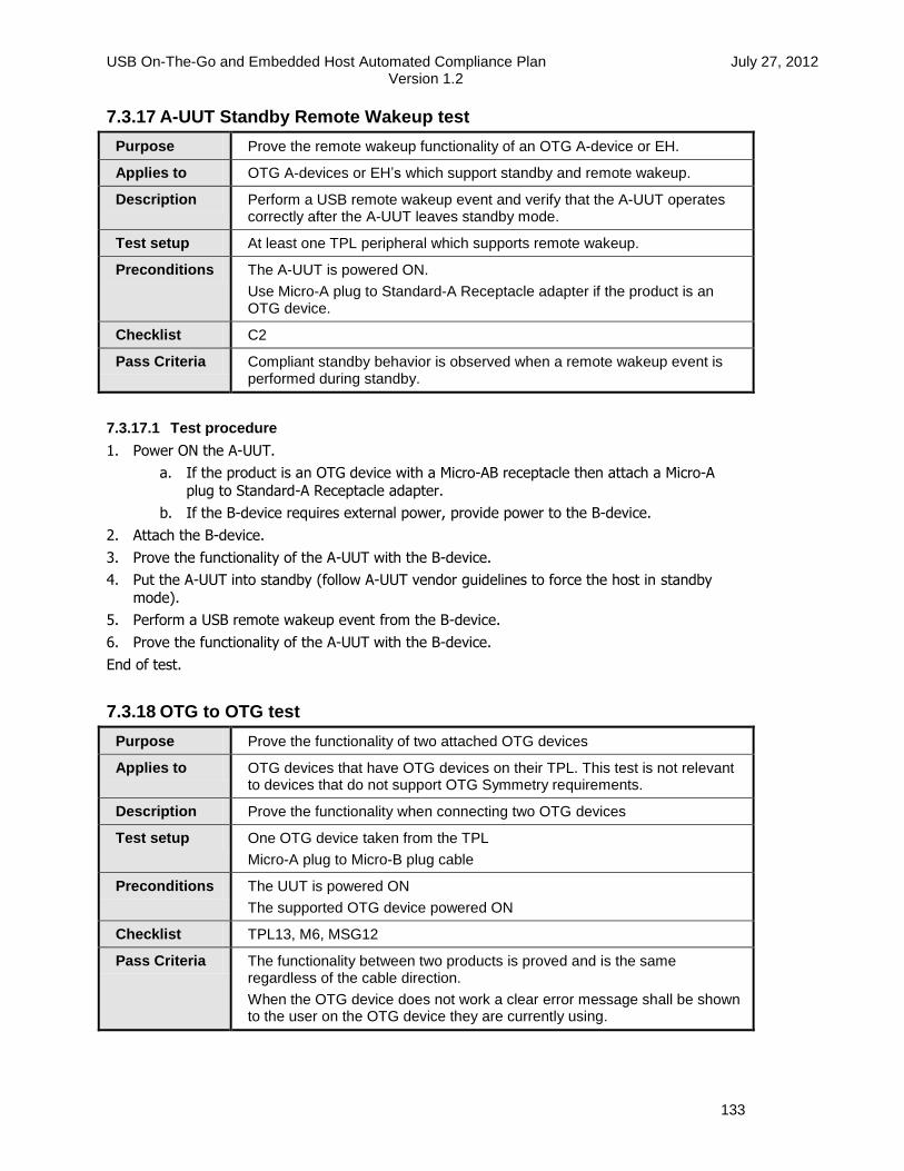
USB On-The-Go and Embedded Host Automated Compliance Plan July 27, 2012 Version 1.2
133
7.3.17 A-UUT Standby Remote Wakeup test
Purpose Prove the remote wakeup functionality of an OTG A-device or EH.
Applies to OTG A-devices or EH’s which support standby and remote wakeup.
Description Perform a USB remote wakeup event and verify that the A-UUT operates correctly after the A-UUT leaves standby mode.
Test setup At least one TPL peripheral which supports remote wakeup.
Preconditions The A-UUT is powered ON.
Use Micro-A plug to Standard-A Receptacle adapter if the product is an OTG device.
Checklist C2
Pass Criteria Compliant standby behavior is observed when a remote wakeup event is performed during standby.
7.3.17.1 Test procedure
1. Power ON the A-UUT.
a. If the product is an OTG device with a Micro-AB receptacle then attach a Micro-A
plug to Standard-A Receptacle adapter.
b. If the B-device requires external power, provide power to the B-device.
2. Attach the B-device.
3. Prove the functionality of the A-UUT with the B-device.
4. Put the A-UUT into standby (follow A-UUT vendor guidelines to force the host in standby
mode).
5. Perform a USB remote wakeup event from the B-device.
6. Prove the functionality of the A-UUT with the B-device.
End of test.
7.3.18 OTG to OTG test
Purpose Prove the functionality of two attached OTG devices
Applies to OTG devices that have OTG devices on their TPL. This test is not relevant to devices that do not support OTG Symmetry requirements.
Description Prove the functionality when connecting two OTG devices
Test setup One OTG device taken from the TPL
Micro-A plug to Micro-B plug cable
Preconditions The UUT is powered ON
The supported OTG device powered ON
Checklist TPL13, M6, MSG12
Pass Criteria The functionality between two products is proved and is the same regardless of the cable direction.
When the OTG device does not work a clear error message shall be shown to the user on the OTG device they are currently using.

USB On-The-Go and Embedded Host Automated Compliance Plan July 27, 2012 Version 1.2
134
7.3.18.1 Test procedure
1. Power ON the UUT.
2. Attach the Micro-A plug to the UUT.
3. Attach the Micro-B plug to the supported OTG device.
4. Prove the functionality of the UUT with the OTG B-device.
5. Detach cable on both sides.
6. Attach the Micro-B plug to the UUT.
7. Attach the Micro-A plug to the supported OTG device.
8. Prove that the functionality is the same functionality as seen in step1.
End of test.

USB On-The-Go and Embedded Host Automated Compliance Plan July 27, 2012 Version 1.2
135
8 USB-IF Required Tests
Devices which support features of [USBOTG&EHv2.0] shall undergo additional testing beyond the tests described in this document. This additional testing is a subset of existing tests for USB peripherals and USB host controllers.
Table 8-1 describes which tests are required for full USB-IF certification by an EH with a Standard-A connector.
Table 8-2 describes which tests are required for full USB-IF certification by an EH with a Micro-AB connector.
Table 8-3 describes which tests are required for full USB-IF certification by an OTG device.
Table 8-4 describes which tests are required for full USB-IF certification by an EH B-port (not a Micro-AB host port) or a Peripheral-only B-device.
The following symbols are used in these tables:
Always required
* Required if feature is supported
** Required if there are multiple downstream ports
Table 8-1: Embedded Host test requirements for Standard-A connector
USB-IF test
USB speed
Au
tom
ate
d T
es
t C
h6
Ma
nu
al T
es
t C
h7
Dro
op
DS
LS
SQ
T
DS
FS
SQ
T
DS
HS
Ele
ctr
ical
High Speed Host ** * *
Full Speed Host ** * *
Low Speed Host **

USB On-The-Go and Embedded Host Automated Compliance Plan July 27, 2012 Version 1.2
136
Table 8-2: Embedded Host test requirements for Micro-AB connector
USB-IF test
USB speed
B A
Av
g C
urr
en
t
Ba
ck
-Vo
lta
ge
Inru
sh
Au
tom
ate
d T
es
t c h
6
Ma
nu
al T
es
t C
h7
Dro
op
DS
LS
SQ
T
DS
FS
SQ
T
DS
HS
Ele
ctr
ical
High Speed Host ** * *
Full Speed Host ** * *
Low Speed Host **
Table 8-3: OTG device test requirements
USB-IF test
USB speed
B A A/B
IOP
Go
ldtr
ee
Av
g C
urr
en
t
US
BC
V
Ba
ck-V
olt
ag
e
US
HS
Ele
ctr
ical
US
FS
SQ
T
Inru
sh
DS
HS
Ele
ctr
ical
DS
FS
SQ
T
DS
LS
SQ
T
Ma
nu
al T
es
t C
h7
Au
tom
ate
d T
es
t C
h6
FS B/ FS A *
HS B/ FS A *
FS B/ HS A *
HS B/HS A *

USB On-The-Go and Embedded Host Automated Compliance Plan July 27, 2012 Version 1.2
137
Table 8-4: EH B-Port and Peripheral-only B-device test requirements
USB-IF test
USB speed
IOP
Go
ldtr
ee
Av
g C
urr
en
t
US
BC
V
Ba
ck-V
olt
ag
e
US
HS
Ele
ctr
ical
US
FS
SQ
T
Inru
sh
Au
tom
ate
d T
es
t C
h6
FS B
HS B
8.1 Description of required tests
The following sections briefly describe each of the required tests. For a full description of the tests please refer to the links given in Section 8.2.
8.1.1 IOP Goldtree
The interoperability Goldtree is the interoperability functionality test of the B-device.
8.1.2 Avg Current
Measure the average current when the device is in worst case power consumption during Unconfigured, Configured, Active and Suspend modes. For HS devices this shall be done in HS and FS mode.
For battery charging devices please also check the Battery Charging compliance program.
8.1.3 USBCV
The USB20CV and USB30CV Chapter 9 tests shall be performed. If supported device class specific tests should such as MSC, HID, OTG, UVC, PHDC, HUB should also be performed.
For HS device these tests shall be done in both HS and FS mode.
8.1.4 Back-Voltage
Check that no voltage is driven back from the device to the host when not connected.
8.1.5 US HS Electrical
Upstream high speed electrical.
8.1.6 US FS SQT
Upstream Full Speed signal quality. Measure using a 2m cable.
8.1.7 Inrush
The inrush current event.
8.1.8 DS HS Electrical
Downstream High Speed Electrical tests. Note: it is mandatory for the Host to enter the required HS electrical test modes via PID/VID detection (See [USBOTG&EHv2.0]).

USB On-The-Go and Embedded Host Automated Compliance Plan July 27, 2012 Version 1.2
138
8.1.9 DS FS SQT
Downstream Full Speed Signal Quality. Measure using a 5m cable.
8.1.10 DS LS SQT
Downstream Low Speed Signal Quality. A LS device must have a captive cable and therefore its only possible to measure at the end of the cable with the A-Plug.
8.1.11 Droop
If EH has multiple downstream ports the droop effect on the other port may not exceed 330mV.
8.1.12 Automated Test Ch6
See Section 6 of this document.
8.1.13 Manual Test Ch7
See Section 7 of this document.
8.2 Test procedures and tools
The test procedures can be found at: http://www.usb.org/developers/docs/
Updates on these procedures can be found at: http://compliance.usb.org/http://compliance.usb.org/
The tools used can be found at: http://www.usb.org/developers/tools/
Technical questions relating to compliance should be sent to [email protected].