u.s.-mexican am band agreement (1986) - the united … · of this agreement and the provisions of...
TRANSCRIPT
,C’
AM AGEZXZ,yT
BZTVZZX
T9Z
UNITED STATES
AND
ZEXICO
1986

AGREEMmT 3ETWEEN THE GOVEWMENT OF THE UNITED STATES OF AMERICA MD
TtiE GOVE.RNMENT OF THE UNITED MEXICAN STATES AN3 RELATING TO
TtiE AiY BROADCASTING SERVICE IN 'WE MEDIUM FREQUENCY B.WD

AGREEXEXT BETWEEN THE GPVERNMENT OF THE UNITED STATES OF AMERICA
FND THE GOVERNMmT OF THE UNITED lyEXICA+\ STATES XELATING To
TE AM BROADCASTING SERVICE IN THE MEDIUM FREQUENCY SAND
The Government of the United States of America and the
Government of the United Mexican States, desiring to continue their
mutual understanding and cooperation concerning AM Broadcasting and
recognizing the sovereign right of both countries in the management
of their own services, taking into account the provisions of Article
31 of the International Telecommunication Convention, Nairobi, 1982
and Articles 6 and f of the Radio Regulations, 1982, annexed to the
Convention, in order to protect the broadcasting stations in the two
countries and to improve the utilization of the frequency band
535-160s kHz allocated to this service, have agreed as follows:

ARTICLE 1
Definitions .
For the purpose of this Agreement, the following terms skall have
t-he meanings defined below:
Mminis;ration:
Agreement:
t
I.F.R.B.:
The Federal Communications Commission
of the United States of America and the
General Directorate of Concessions and
Permits Of Telecommunications of the
Secretariat of Communications and
Transportation of the United Mexican
States, respectively:
This Agreement and its Annexes:
The International Frequency
Registration Board;
Assignment in Conformity A frequency assignment
with the Agreement: appearing in t'ne Plan;
f

4
Objectionable Interference: The interference caused by a signaL
that exceeds the maximum permissible
field strength within the protected
contour, in accordance with the values
determined according to the provisions
of tinex 2 to the Agreement;
Plan: The frequency assignment Plan as
contained in hnex 1 to the Agreement
and the modifications introduced as a
result of the application of the
procedures of Article 3 of the
Agreement:
Rio de Janeiro Plan: The frequency assignment Plari' as
defined in the Regional Agreement for
the Medium Frequency Broadcasting
Service in Region 2 (Rio de Janeiro,
1981).2/
I/ Any reftrence in this kgreement to the Regional %reement of Rioze Janeiro does not prejudge the legal status O f the RegionalAgreement for either contracting party.
w

S
Adoption of the Plan
The Plan set forth in Annex 1 to this Agreement consists of a
list of assignments with technical parameters agreed upon by the two
administrations. Broadcasting stations shall ‘02 brought into
service only when in conformity with Annex 1 or any modification of
it resulting from app lication of Article 3.
ARTICLE 3
Procedure for Modifications to the Plan
3.1 When an Administration proposes to modify the Plan,
i.e.,
-to modify the characteristics of a frequency
assignment to a station shown in the Plan,
whether or not the station has 'been brought
into use, or

-to introduce a new assignment into the Plan, orm
3.2
3.2.1
3.2.2
-to cancel a frequency assignment to a station,
the following proceciure shall be applied
simultaneously with or prior to the notification to
the '1.F.R.B. (for modification to the "kio de Janeiro
Plan").
Proposals for modifications in the characteristics of
an assignment and for the introduction of a new
assignment.
administration proposing to modify the
characteristics of an assignment in the Plan or'.
introduce a new assignment shall seek the agreement of
the other Administration and shall send in accordance
with Article 4 the necessary information via
registered mail.
Any assignment in conformity with the Agreement shall
‘be considered as adversely affected when calculations0
based on Annex 2, indicate that objectionable
interference would occur as a result of the proposed
modification to the Plan.

3.2.3
3.2.4
If an Administration which received a notification
consi&is that a proposed modif ication to the Plan is
acceptable, it shall communicate its agreement t0 the
other Administration as soon as possible and shall
inform the 1-F-R-B. accordingly. If the notified
Administration considers that . the proposed
modification to the Plan is unacceptable, it shall
communicate its reasons to t'ne notifying
Administration within 90 days from the date on which
t-he notification by registered mail is received. If
no comment has been received within the 90 day period,
the not i fyi ng Administration may proceed with its
modification and advise the 1-F-R-B. that the
agreement of the other Administration has been
obtained. On those exceptional occasions when the
period for res,Donding to a notification is found to be
insufficient the Administration which receives a
notification may request an extension of such period.
The agreement referred to in 3.2.1 is not required for
a proposed change in the characteristics of an
assignment in conformity wit-n the Agreement if it
.entails no increase in t'ne radiated field strength In

3.2.5
3.3
any direction, and if a change in site of the stationm
is involved, this change is limited to 3 km or 5% of
the distance to the nearest point on the border of the
other country, whichever is larger, up to maximum of
10 km. The distance is 'calculated from the site first
registered in the Plan or subsequently registered in
the Plan as a result of the application of the
provisions of 3.2.1. In any event, such site change
shall not produce a groundwave contour overlap
prohibited under 4.9.4.2 of Annex 2 to this
Agreement. However, no protection will & required
beyond the level of protection which was already
accepted before the proposed modification.
All Modifications to the Plan will be registered in it
when the agreement of the other Administration has
been obtained or when the time period for responding
to the Notification established in 3.2.3 has expired
and no such response has been received.
Cancellation of an Assignment
When an administration decides to cancel an Assignment
in Conformity with the Agreement, it shall immediately

9
.
t
notify * t*ne other A2ministration. *Y such
notification of cancellation Of an Assignment in
Conformity with the Agreement will be considered an
abandonment by the notifying Administration of any
right arising -i ZOZI that assignment unless,
simultaneously with such canceI,lation, t'ne
Administration notifies a new assignment of the same
frequency t0 substitute for the cancelled assignment..
In such case, the Administration shall retain, with
respect to the substituting assignment, the rights and
obligations of the cancelled assignment, including
. priority. However, such new assignment will not be
permitted to cause objectionable interference to
existing stations in the other country at a level in
excess of that caused by the cancelled assignment, and
which has ken previously accepted.

4.1
4.2
e ARTICLE 4
Notification procedure
The date of a notification will be deterruined by the
date on which the required information submitted in
conformity with this Article is received by the other
Administration. If a conflict ,exists between two or
more valid notifications, priority will be given to
the notification which has the earlier date of receipt.
The information required for the notifications
referred t o i n Article 3 shall be provided in
conformity with Annex 1 to this Agreement. In the
case of a modification of technical characteristics,
there shall be an indication of which parameter(s) are
modified. . In order to facilitate the verification of
the data, directional antenna parameters shall be
supplemented by sample radiation values calculated in
five azimuths using the corresponding vertical angles,
preferably in directions in which there is maximum and
minimum radiation.

11
4.3
4.4
4.5
hY -notification of the bringing into use of t‘nE
modification of an Assignment in Conformity with the
Agreement which involves a change in freqency Shdl:
have the effect of canceIlin5 the fOrner assignmen&Land will constitute the simultaneous notification of s
.new assignment which shall be given the priority
corresponding to the notification of a new assignment.
Each Administration shall notify the date that an
Assignment in Conformity with the Agreement or a
modification of an Assignment in Conformity with the
Agreement begins or ceases operation. Such
notification shall ke made within sixty days following
such date, and the I.F.R.B. shall be notified
accordingly.
Any Assignment in Conformity with the Fqreement shall
ke deleted from the Plan and cease to be protected
from interference unless it is brouc;ht into use within
five years from the date on which t'he respective
station has been r,otified 2nd accepted. This is
without prejudice to the provisions of paragraph 4.7
of this Article.

12
4.6
4.7
4.8
my modification of any Assignment in Conformity with
the Aqreement shall & deleted from the Plan and cease
to be protected from interference unless it is brought
into use within five years from the date on which the
respective modification had been accepted.
For the purposes of paragraphs 4.5 and 4.6 the
aforementioned periods may, in special cases, be
extended for successive periods of one year upon
notice to the other Administration within the
effective period of the notification in question.
Such notice must include a detailed description of the
extraordinary circumst antes which would justify such
extension..
~,ny notification of a new or modified Assignment in
Conformity with the Agreement which does not include
all the required informat ion set forth in Annex 1,
shall be returned by the receiving Administration, and
the assignment involved shall receive no protection or
priority date. Nevertheless, if the Administration
notifies a directional antenna and the complete
information

13
4.9
.
4.10
is not provided, the notifying Administration shall
submit Section II, Part II of -klneX 1 with its initial
notification. The receiving %mir,istiZtiOn may return
this notification if the supplementary information is
not received within 6 months zfter receiving the
initial notification.
Wnen an Administration notifies a modification to an
Assignment in conformity with t'ne Agreement which has
'been brought into use, the new notification will be
protected from subsequent object ionable interference
but will not supersede the previous Assignment in the
Plan until it is brought into use.
When an Administration notifies a modification to an
Assignment in conformity with the Agreement which has
not 'been brought into use, the new notification will
supersede the previous notification when it is
accepted.

5.1
ARTICLE 5e
Technical Criteria
The Administrations shall apply in carrying out this
Agreement, the technical criteria contained in Annex
2, as may 'be amended from time to time pursuant to
Article 9.
5.2 - Notwithstanding the requirements of paragraph 4.9 of
Annex 2, the Administrations agree to consider and
ana ly 2e all reasonable measures to accommodate
modifications of technical parameters agreed upon, of
existing or authorized stations in order to amelioratr
the impact of objectionable interference received from
Administrations not parties to this agreement which
seriously affect one or tith parties to this agreement.

15
6.1
6.2
Extended Eaurs of Operation
Scope
"Stations with extended hours of operation" are Clasc
B and C stations operating during a period startinc
two hours before sunrise and endin two hours afte:
sunset, local time, with protection requirements
determined in accordance with Apgendix 7 to Annex 2.
Protection
A notified and accepted station operating at nighttime
shall have priority .over extended hours of operatior
and shall be protected in accordance with 4.9 of
Annex 2.

6.3 Notification
"Stations LhW' L extended hours of operation" that
comply with the provisions of this A r t i c l e shall be
considered acceptable. Stations l a t e r found to be
operating in a manner inconsistent with the protection
requirements of this Agreement must make the necessary
changes in t'neir extended hours of operaticn to afford
the required protection. Proposals for stations with
extended hours of operation shall be notified in
accordance with t'ne applicable procedures established
in Annex 1. Notification shall include 'the exact
operating characteristics of each proposed station.
ARTICLE 7
Termination of Previous Agreements
TICS Agreement supersedes the existing Agreement
between the United States of America and the United Mexican States
Concerning Broadcasting in the Standard Broadcasting Band
(%s-l6Ojk,Yz) and the existing Aureement between the United State-'d
of America and the United %exican States Concerning the Operation of
broadcasting Stations in the StanCard Sar,d (5354605 kh), D u r i n g i
Limited Period Prior to Sunrise and After Sunset, 'both signed or
December 11, 1968.

Resolution of Conflicts
In the case of any discrepancy between the ProviSiOns
of this Agreement and the provisions of another bilateral or
regional agreement relating to broadcasting in the frequency band
5354605 kEz, the provisions of this Agreement will prevail insofar
as mutual relations between the United States of America and the
United Mexican States are concerned.

ARTICLE 9
Amendment of the Agreement and the Annexese
.Except for modif ications to the Plan, which are
governed by Article 3, the Agreement and the annexes hereto may
be amended by cooperat i ve efforts of ‘ the two Administrations.
These amendments would become effective when an exchange of
Diplomatic Notes takes place between the Department of State of
the United States of America and the Secretariat of External
Relations of the United Mexican States.
ARTICLE lo
Coming into Force and Duration
This Agreement shall come into force on the datel .
on which both parties notify each other through diplomatic
channels that they have concluded their respect i ve
constitutional procedures and shall continue in force unti l a
new agreement is substituted or until it is denounced by either
party.

19
w ARTICLE 11
Termination of the Agreement
Ei t’ner Government may. terminate t h i s Agreement Sy
written notice of denunciation to the other Government throuq
diplomatic channels. The denunciation will be effective one yea
a f t e r receipt of the notice.
IN WITNESS WKEZIEOF, the respective Plenipotentiarie
have signed tSis Agreement.
DONE in duplicate, in the English and Spanis?
languages, each having equal authenticity, at Mexico City, District<
Federal this . day of 1986.
.For the Government of the
United States of America
For the Governxuent of the*.
United Mexican States

ANNEX 1
to the Agreement
INFORMATION TO BE CONTAINED LN LISTINGS ANDIN FORYS FOR NOTIFICATION PURPOSES
For the purposes o f this Agreement the forms to be usedin ac cord ante with Art i c le 3 vi1 1 be the same as thosereferred to in Annex 3 of the Regional Agreement ConcerningRadio S e r v i c e in the Broadcast Band in Region 2 , s igned atRio de Jane iro , 1981 .
As an except ion, in the case o f noc i f i cat i on o f s tat i onsoperating during extended hours the form from ?art V ofthis Annex will be used.
1. Parts I through V descr ibe the data to be not i f i ed and the forms cob e u s e d i n n o t i f i c a t i o n . Part VI descr ibes the Plan.
2 . An administrat ion wishing to submit the equivalent in format ion onmagnet ic tape or by other e lectronic means , shal l submit such data only in theform& accepted by the other administrat ion .
3. Five forms and a List are adopted; each o f which corresponds to thefo l lowing Lnformation:
PART1 :
PART 11 :
PART 111 :
PART LV :
PARTV :
PART VI :
General informat ion on the transmitting stat ion.
Sect ion I: C h a r a c t e r i s t i c s o f d i r e c t i o n a l a n t e n n a s(when the antenna design is known).Sect ion 11 : R a d i a t e d f i e l d in v a r i o u s s e c t o r s ( f o r u s ewhen the antenna design is not yet known).
Addit ional informat ion for direct ional antennas withaugmented (modified expanded) pat terns.
Supplementary in format ion for top - loaded ors e c t i o n a l i z e d t o w e r s u s e d f o r d i r e c t i o n a l a n domnidirectional antenna systems.
Supplementary informat ion for extended hours o foperat ion .
The Plan.
4. T h e A d m i n i s t r a t i o n r e c e i v i n g t h e n o t i f i c a t i o n m a y r e t u r n forms *i.chhave n o t b e e n c o m p l e t e d c o r r e c t l y .
5. When known, the IFRB Ser ia l Number shaLL be inserted on each form bythe not i fy ing Administrat ion . Ot hervbe, t h e s p a c e p r o v i d e d s h a l l b e Leftblank.

Box No.
01 A dminisrra tion
Indicate the name of the administration. the shoe; number and the dare on which the form wascompleted;
02
03
04
OS
06
07
08
PART I
~eoarol Iaformd-
Assigned frequency (k?i:)
Name of rhc transmirring sration
indicate the name of the locality or the name by which the station is known. Limit the number oflitters and numerals to a total of 14;
Calf sign
This information is optional. Limit the number of letters and numerals to a total of 7;
additional idcnrificarion
Indicate any additional information which may be considered essential for complete identifica-tion. Where this information is not essential, this box may be left blank:
Slabon CIass (A. B or C)
Insen A. B or C according to the station cfasscs defined in Chapter 1 of Annex 2 to theAgreement:
Operarional status
Enter 0 for a station already in operation and enter P for a station to be brought into operation:
Country
Indicate the name of the country or geographical area in which the station is louted. i&e thesymbols in Table 1 of the Reface to the International Frequency List;
09 Geogmphical coordinates of the transmirring sration
Indicate the geographical coordinates (longitude and latitude) of the transmitting antenna site indegrees, minutes and seconds. Seconds need to be entered only if available. Delete the letter N orS, as appropriate. If no seconds are indicated, the IFRB will use a value of 0 in its calculations:
II
12
13
21
Indicate the reason for the applicarion of Article I :
a) New assignment:
b) Modification of the characteristics of an assignment recorded in the Plan:
c) Cancellation of an assignment:
Indicate whether the modification is of the type spcciftcd in section 4.2.14 of Article J of theAgreement:
In the case of a new station, indicate the date of bringing into se&c:. In the c&of a Change inthe charactetisrics of a station already recorded in the Plan. indicate the date of star( of opaLiOnwith the modified chanacristics or the date of cessation of operation;
DAYTIME OPERATION
Station power (k W)
Indicate the carrier power supplied to the antenna for daytime operation (to the second decimalposition for powers less than I kW):

25 r.m.s. value of ndiation (mV/rn at I km) for drytimc nation power:
26 Antenna type e
Indicate hctc the tw of a&en& used for daytime operation- Use the symbols as follows:
A- Simple omnidirectional antenna:
B- Directional antenna when the design is known (complete Pan II, Section I):
C- Directional antcnnr where the design is not known. indicated by sectors of radiation(complete Part II. Section II);
1 - Top-loaded omnidirectional antenna (complete Part IV);
2 - Sectionalized omnidirectional antenna (complete Part IV);
27 Simple venical antmna eircrricol height
indicate here the electrial height. in degrees, for a simple vertical antenna in use for daytimeoperation. In the case of an antenna type ocher than A, this box should be left blank;
NlGHT-TIME OPERATION
31 Slation power (k W)
Indicate the carrier power supplied to the antenna for night-time operation (to the second decimalposition for powers less than 1 kw): -.-.
3s r.mJ. value of radiation fm V/m ar / km) for night-rime station pon*er .I
36 Antenna fype.
Indicate the type of antenna used for night-time operation (use the symbols in Box No. 26);
37 (See Box No. 27);
44 RemorkF
Indicate here any necessary additional information, such as. the identification of the synchronizednetwork to which the station belongs. If shared time operation is intended, indicate in this boxand identify the other assignment involved;
.
Coordination under ankle 4
C o u n t r y - Indicate the name of the countries which may be affected and with whichcoordination is considered necessary, using the symbols in Table I of the Prefaceto the International Frequency List:
In ptogtess - Add an ‘X” if coordination is under way with these countr+
Acceptanceo b t a i n e d - Indicate with an -X’ if coordination has been successful.
Annex Up.3

CHARACI-ERISTICS OF A BROADCASTING STATION
IName of the surion 0.03. I
Gllsiga @aTransnlitting , 0. Istation
Addiciodidcncif~tioa 0,05, 1sution dms (A. E or cl
011 a) NWcl
b) Modifiation of thec l
c) Gaccflrtion ofusigamalt charaaedtia of uI xn utignmmt
ruignment recordedin tk Plan
012 Modificacioa undersalioa 4.2.14
YCS cl NOcl
013 Date of brinw into scnkor ceurfion of opemioa I I I
Ry Month Yur
cl
Sutioa puamacn
status of the sutioa (0 or P)
Sucioa powa qw)
r.m.s. VJUC of mdiarial (mV/m i I km)(auptwhcnsy&oiBorCtopevrirrbX24tX34)
-m=
Night-time operation

PART II
Description of the directioaal l ~ltenm-
1. The form for Pan II Section I is used when the design of the directional antenna -is known. When adirectional antenna is intended 10 be used. but the desrgn is not yet known.’ the form Part II Section II should be
used. The latter form should be replaced by a completed Pan II Section I form as soon as the design parametersare determined.
7-. Administrations are invited to use Part II of the form to furnish the eicctrical characteristics of theantenna. From the information thus furnished. the IFRB will determine the radiation pattern.
3. When Pan II of the form is not suitable for describing a paniculat type of antenna. admin&ations maycommunicate the parricttlan of the antenna in question on a separate sheet, taking care that a11 the parameters
nectssary for the calculation of the radiation diagram have been. included.
4 Radiation diagrams shall be used only when. the information requested in Pan II is not available. SeeAppendix 3 to Annex 2 to the Agreement .
.
A n n e x Up.5

PART II - SEmION I
Descriptioa of tbc dirtctioaal antenna consisting of reflical conduaon
htmctioa~ for compietirtg the form
.
Box lvo.
01
02
03
04
lndiate the name of the transmitting station:
Country
Indicate the country or geographical area in which the station is located. Use the symbols inTabie 1 of the Reface co the international Frequency List:
Indicate the hours of opcntion for which the given characteristics of the antenna are applicable,The symbols D or N shall be used to indicate chat the station operates for the daytime ornight-time period respectively. When the same operation is used for both daytime and night-time,enter the two symbols -0” and -N’:
indiate the total number of towers constituting the array.
Coiumn No.
05
06
07
08
This column SLOWS the serial number of towers. as they will be described in coiumns 06 to 12:
Indicate here the ratio of the tower fteId to the field from the reference tower:
Indicate here, in degrw. the positive or negative difference in the phase angle of the field fromthe tower with respect to the field from the reference tower:
Indicate. in degrees. the electrical spacing of the tower from the reference point, defined incolumn. 10:
09
10
Indicate. in degrees from True North, the angular orientation of the tower from the referencepoint indicated in column 10:
Define the reference point as follows:
0 : where the.spacing and orientation are shown with rcspea to a common reference point whichis gcneraliy the first tower;
II
12
I : where the spacing and orientation are shown with respect to the previous tower:
Indicate the electrical height (degrees) of the tower under consideration:
Tower stmcrure
This cbiumn should contain a code from 0 to 2 to indicate the stNCture of each tower:
0 - simple vertical antenna Codes I and 2 are used in Parr IV to indicate theI - top-loaded antenna characteristics of the vatious stmcturcs. They are also
2 - sectionalized antenna used for the identification of the appropriate formuiafor venical radiation in Appendix 4 co Annex 2.
Herr: In the absence of a specific code to refer to other types of seaionalircd antennas. administrations mayuse the codes indiutcd in Appendix 6 to Annex 2
Box cvo.
I4
IS
I4
r.m.s. value of radiation (mV/m at I km):
Type of pattern:.
T - theorctial
E - expanded
M - augmented (modified expanded):
Special quadrature factor for expanded and augmented (modified expanded) patterns in mV/m atI km (to replace the normal expanded pattern quadrature factor *when special precautions aretaken to ensure pattern stability):

FORMTO BE USED IN APPUUDON OF ARTICLE 1 OF=
MF BROWC AGREEMEl-
!
CHJUL~CERETICS OF A BROADCASTING STATION
PART II - section I
DESCRIPTION OF A DIRECrIONAL WTENNA COIWSR?‘JG OF VERTICAL COMXJCTORS
Form No. JDate I I
0101Name of transmitit station
1Hours ofOpCd0n
(D,NorDrcr)
(Use I supplezncn~ that in asu what there an more than 10 towers.)
0 14 r.m.s. v8iue of 0 15 Type of patumO-. E or M) 016 speciai qusdraturc
tl¶coretkal rdiition furor
mV/m
IO17 SUPPLES~E?~-TARY INFORMATSON.
l/c, 7

PART 11 - SECTION II
1. In the absence of a detailed descriptjon of the directional menna Wcrn, an indication of the radiatedfteld limitations in specific sectors is required. fn these cases. the radiation pattern (O’-360”) is subdivided insectors’with an indication of the maximum radiated field for each SCCIO~.
2 This form is to be used for a proposed station only (‘P- entered in Pan I. Box 07).
3. ntc Shct No. box is for the convenience of administrations. Indicate the date on which the form wascompleted.
Iostructioas for completing the fonn
Box No.
01
02
03
Column No.
18
19
28
29
Box No.
20
Name (usually town or loaliiy) of transmitting station;
Country
indicate the country or geographical area in which the transmitting station is located. using thesymbols in Table 1 of the Preface to the International Frequency List:
.
Indicate the hours of operation for which the given characteristics of the antenna are apphcable.The symbols D or N shall be used to indicate that the station operates: for the daytime ornight-time pctiod respectively. When the same operation is used for both daytime and night-time.enter the two symbols ‘D” and ‘N”.
DAYTIME OPERATION
Sectors of radiation in degrees from True North for daytime operation. The entire circumference .
from 0 to 360 degrees shall be specified;.
Maximum radiated field strength in the sector indicated in column 18, in the horizontal plane insmV/m at 1 km: (see Appendix to this Annex):
NIGHT-TIME OPERATION
Sectors of radiation in degrees from True Nonh for night-time operation. The entire cirtumfer-ence from 0 to 360 degrcts shall be specified:
Maximum radiated field strength in the vertical plane in the sector indicated in column 28. inmV/m at 1 km.
Any further information which should be included in the IFRB weekly circular. AnY funherexplanatory notes for the information of the IFRB may be attached.
Nore: This form should be rtpked by the fov conaponding to Pan II. Section I, duly completed- fi SOonas the antenna design is known.

FORMTo BE USED IN APPLICATION OF ARTICLE 4 OFT?=
MF BRO-G AGREEMENT
WRB Scd No.
1
c~~RETICS OF A BROADCmmG ~-I’iU’ION
Fom No. 1
0101 IC-W
p&nc of aansmiLtin$ swioo .
NO=: T&s form should only be used for +XUied stations (Symbol P in box 20 or30 in pti 1).
I Daytime opcdon I
018 019
SccrOTof radiation(dew&
maximum Addsum#th in the
horizond pknc(mV/m at 1 km)
I Night&e opartioa - _.
028 0’29 .‘I- - -. *scCr0t .
of radiation
I -
~usn tidd&cqch in my VatiUJ
Ww=) . . - plure$ll the rector(mV/m 11 1 km)
020 SUPPLEMENTARY fNFOR.HATtON
. .?, CI

PART 111
Dcrcri~tioa ottbe panmasem of direcsjoo~l mteaau 4thrugmtntd (modified txprodcd) prttem
1. ~;in 11 of this Annex contains the information for directional antenna systems operating with theoreticaland expanded patterns. However. some Itarions operate with augmcnred (modified expanded) directional antennapatterns. IL these cases. additional akulacions arc performed., cince the expanded radiation is calculated. codetermine the radiation from the augmented (modified expanded) directional antenna pattern. This Pan containsthe additional parameters requited for augmented (modified expanded) patterns.
7I. If Pan. 111 is submitted. a corresponding Pan II must also be submitted.
3. Pan III should be submitted only if Box 13 of Section I of Pan II cbntainr the symbol -,&fa forMaugmenrcd (modified expanded)“.
Box uo..
01
02
Indicate the name of transmitting station:
country
Indicate the country or geographical arca in which the station is located, using the symbols in -. *Table 1 of the Preface to the International Frequency List;
03 Ind&atc the houn of operation for which the antenna characterisrics given are applicable. The.symbols D or-N_shall be used to indicate that the station operates for the daytime and night-time.enter the two symbols ‘D” and ‘N”;
Indicate the total number of augrkntations which are used.- It must be 1 or greater than 1. *.04
Coiumn uo
05
04
07
indicate the serial number of the augmentations. as they will be described in columns 06. 07and 0% (see section 27 of Appendix 3 to Annex 2):
Indiatc the radiation at the central azimuth of augmentation. This value should always be equalto or greater than the vaiuc from the theoretical pattern :
Indicate the central azimuth of augmentation. This is the CIIWC of the span:
08 Indicate the total span of the augmentation. Half of the span will be on each side of the mu-alazimuth of augmentation. Spans may overiap: if so. augmentations arc processed clockwiseaccording to the central azimuth of augmentations.
Box lvo.
09 Supplementary information. Indicate any supplementary information conctming augmcnrcd(modified expanded) pancms. If a supplementary sheet has been used for further augmentations.please indicate in this box.

. ~cr~~~smcs OF A<oA.DcASTMG STATION
DEScm!TlON OF THE PAJuMETuls OF DIRECRONAl -ti AUG-(MODIFIED E%PANDED) PATTERNS. TO BE SUEMn-rrP WE-
THESYhfBOLMlS- IN PART II SECTION 1 Box 13
Form No. I
Name of PMImitting swioa couavr Hours of -foulOpClXCiOU oumbcf of(D. N or DN) wmcnutioru
~~pnenusion No.
‘009 SUPPLEMENARY INFOlW4ATlON

PART IV
Supplcmcntrty iaformatioa for toploaded or doaahcdtowers used for omnidirtctioasl and dire&o-l 8JWnlIaS.
1. Where an omnidirectional antenna is top-loaded or sectionalized. the figures 1 or 2 will have been enteredin Parr I. Box 26 and/or 36. Proceed as for a single tower of a directional antenna.
2. When an antenna tower of a directional antenna is. &her top-loaded or seaionalired. column 12.Scaion 1 of Pan 11 will contain either a figure 1 or a figure 2. Ikte numerals describe the parricuiar type oftop-loaded or sectionalized antenna used, as described below:
Box No.
01
02
03
Column No.
04
Name of the station:
Country
Indicate the country or geographical area in which the station is located. using the symbols inTable 1 of the Reface to the International Frequency List:
Indicate the hours of operation for which the given characteristics of the antenna are applicable.The symbols D or N shall be used to indiute that the station operates for the daytime ornight-time period respectively. When the same operation is used for both daytime and night-time,enter the two symbols ‘D” and ‘N”.
Tower number:
Columns 5 to 8 show the values of four characteristics of the el~menu constituting a top-loaded orsectionalized antenna. Each of these columns may contain a figure representing the value of a given characteristicas described below:
OS Code used inCo!. 12 l(Part 11 - Section I)
I
2
06 Code used inco/. I2 w(Part II - Section I)
1
2
07 Code used inCal. 12’(Part II - Section I)
1
2 Total height of antenna (degrees);
Desctiprion of the characttrirtic the value of whichis given in tht column (these values are usedin the equations given in Appendix I to Annex 2)
Electrical. height of the antenna tower (degrees):
Height of lower section (degrees):
Description of the characteristic the value of whichis given in rhc column (these values ate usedin the equations given in Appendix 4 to Annex 2)
Difference between apparent electrical height (based on cuncnt distribu-tion) and actual height (degrees);
Difference between apparent electrical height of lower section (based oncurrent distribution) and actual height of lower section (degrees);
Desniption of the charactrritric the value of whichis indicated in the column (these values are used
.
in the rquationr contained in Appendix I to Annex 2)
Blank:
.

Column No.
08 Code used in Description of the charactatitic the value of whichCal. 12 l is indicatea in the column (these values are used(ParI 11 - Section I) in the equations mteted in Appendti 4 to Annex 21
1 Blank:
2 Difference between apparent etc~riul height (based on cumnt distribu-tion) of the total Iowtr and the actual-height of the total tower (degrees).
FORMTO BE USED IN APPLICATION OF ARTICLE 4 OF TKE
MF BROADCASI-INC GREE’ME?+T
IFiXB Scrid No.
1
CHAUCERISTICS OF A BROADCASTING STATION
DESCRIPlION OF TOP-LOADED OR SECl-lOWLIzED TOWERS USED FORDIRECTIONAL OR OMNIDIRECTIONAL -NNA SYSTEMS
Form No. I I mtc I- -1
0101
Nanx of emumining station Country @,NorDW
0 04 0 05 0 06 0 07 0 08'
Tower numba A B C D

-- -- ._
PART V
SUE’PLE?!ENTARY IWOR.UTIOt4 FOR EXTENDED HOURS OF OPERATION. . -
Annexl/p. I 4

FORM
cH;UL~CTENSTICS OF A BROADCASTING S-LUIONw
&sign& frequency (Wz) 0. 02i
Name of the sutioa 0, 03i
CdIsignTruumitting , 1sution
Addicioorl identification 0. 05J
Sutionchss (A. B or 0 0, 06
Coumy 0. 07I
~t,ia~ coordinua of rhe uansmicti~ station N I
s 8 I
0I1 a) Newc l
b) Modifiation of thecl
c) canccIladon ofutignmcnt chxrrcuriscics of an an assignment cl .
usignmcac recordedinthCPkn
012 Modifaation underSection 4.2. I4
YCr clNO
c l
013 Date of bringing into scwiczor cusarion of opcratioa
Day .Monrh Yar
sutioo puaalffcn
SUUJ of rhc surioo (0 or P)
Sution pocus fiw)
r.m.r. value of radiadua (mV/m t 1 km)(a~rwbcasyuhdBorCropcuriUbOX26Or36)
Night-time operation

PART Vf
1.0 The Plan in its entirety consists of the assignments
duly notif ied, coordinated and accepted by both
'Administrations.
-2.0 Both Administrations shall exchange lists periodically,as follows:
List 1: Every six months modifications to the Plannotified during such period shall be exchanged. .
.
List 2: Every twelve months an amended Plan shall be
exchanged which includes all accepted modifi-
cations to the Plan up to that date and shall..supersede the Plan then in force.

( to Annex I)
T y p i c a l radiaiion v a l u e s o f a d i r e c t i o n a l a n t e n n a
I. Introduct ion
tc’hen an administration intends co propose a new station underA r t i c l e s, us ing a d irect ional antenna, and the .ancenna design is not known,the form in Annex 3 , Part IL , Sect ion IL , isxo be used . This form requires
informat ion on the arcs o f suppress ion .
The following information may be used as a ,-de for determiningreALstic values which might be entered on the form.
2 . Xinimum r a d i a t i o n
When the radiated f i e ld i s suppressed in one or more d irect ions so asCO a f f o r d p r o t e c t i o n t o o t h e r s t a t i o n s , the minimum level of radiation
a c h i e v a b l e i n p r a c t i c e (Emin> o v e r a r c s u p t o a b o u t 30 d e g r e e s , i s g i v e n b yt h e following e q u a t i o n :
E =min 10 fi N/m a t 1 km
w h e r e P i s t h e s t a t i o n p o w e r i n k!L Thus the degree o f suppress ion requiredby a p lanned scac ion necessar i ly l imits the s tat ion power to a pract i ca l
va lue . When the maximum suppression is required over wide spans exceeding30 degrees, a considerably more complex antenna array or lower power isusual ly required .
3 . Haximum r a d i a t i o n .
T h e radiated f i e l d i n t h e d i r e c t i o n g e n e r a l l y o p p o s i t e c o t h e dirhctionof suppression tends to increase such that the maximum field achieves anapproximate va lue o f 1 .35 x the r .m.s . v a l u e o f t h e t h e o r e t i c a l r a d i a t i o n i nmV/m a c 1 km.
4. Radiat ion in the o ther d irect ions
In t h e d i r e c t i o n s o t h e r t h a n i n t h e s p a n s o f Emin a n d Emax, t h eradiated f ie ld may exceed the r .m.s . value of the radiation by more than 10Percent .
A n n e x l / p . 17

5 . Tabh of typical values
Stat ionpower( w
1 10 330 4052 .5 16 520 640
3 22 735 90010 32 1040 128025 50 1650 203050 71 2330 2860
T y p i c a l v a l u e s o f E bvh a t 1 k m )w I r.m.s.
E minI
valueI
E+ 10%
max
A n n e x Up. 18

C O t h e
AGBEE?4ErNT BETWEEN THE GOVER!W~ OF TKE
UNXTED ~-!~ICAN STATES MD THE GOVERNMENT
OF THE UNITED STATES OF MERICA RELATING
TO THE AZ4 BROADCASTISG SERVICE IN THE
HEDIUN FREQUENCY BAND
TECHNICAL CRITERIA
To be used in the application of the Agreement
Defiaitions and sytiolsm
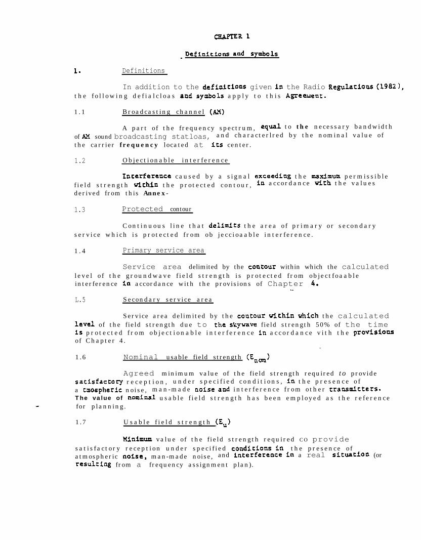
1. Definitions
In addition to the definlcioas given in the Radio Regulatioas (19821,t h e f o l l o w i n g d e f i a l c l o a s aad symbols a p p l y t o t h i s Agreetlenc.
1 .1 Broadcasting channel (AH)
A part of the frequency spectrum, equal to the necessary bandwidth
of AX sound broadcasting statloas, and characterlred by the nominal value ofthe carrier frequency located at its center.
1.2 Object ionable inter ference
Iaterference caused by a s ignal exceediag the maximum permiss ib lef ie ld s trength tichia the protected contour , la accordance tith the va lues
derived from this Annex-
1.3 Protected contour
Cont inuous l ine that delfmfts the area o f pr imary or secondaryserv ice which i s protected f rom ob jecc ioaable inter ference .
1 . 4 Primary service area
Service area delimited by the coatour within which the calculatedl eve l o f the groundwave f ie ld s trength i s protected f rom ob jec t foaableinterference tn accordance with the provisions of Chapter 6.
.-
L.5 Secondary service area
Service area delimited by the coutour tithla which the calculatedLevel of the field strength due to the skywave field strength 50% of the time1s p r o t e c t e d f r o m o b j e c t i o n a b l e i n t e r f e r e n c e la a c c o r d a n c e v i t h t h e provlsionsof Chapter 4.
.
1 .6 Nominal usable field strength (Enam>
Agreed minimum value of the field strength required to providesatfsfactory r e c e p t i o n , u n d e r s p e c i f i e d c o n d i t i o n s , ia t h e p r e s e n c e o fa tsospheric noise, man-made noise and inter ference f rom other traasmltters.The value of nominal usable f i e ld s trength has been employed as the re ferencefor planning.
1 .7 U s a b l e f i e l d s t r e n g t h (E,)
Mfaimum value of the f ield strength required CO providesat is factory recept ion under spec i f ied conditloas Fn the presence o fatmospheric notse, man-made noise, and interference in a real situation (orresultlag from a frequency assignment plan).

1.0 -hudb-frequency protectloa r a t i o ( o r AF p r o t e c t i o n ratf.0)
Agreed minimum value o f the audio - f requeacy s ignal - to - inter ferenceraclo correswnding t o a s u b j e c t i v e l y defined receptioo quauty. T h i s r a t i omay have different values according to the type of service desired-
1.9 zadfo-frequency proteccFoa r a t i o ( o r R F p r o t e c t i o n racfo)
T h e d e s l r e d r a d l o - f r e q u e n c y signal-to-laterference r a t i o which, inw e l l - d e f i n e d couditioas, makes it possfble to obtaia the audio-frequencyp r o t e c t i o n ratio a t t h e o u t p u t o f a r e c e i v e r . These specif led conditionsinclude various parameters such as the frequency separation between thed e s i r e d carrier a n d t h e fnterferiag c a r r i e r , t h e e m i s s i o n c h a r a c t e r i s t i c s( type and percent ‘modulation etc - ) , Leve ls o f input and output o f the receivera n d f. ts characteristfcs ( s e l e c t i v i t y , sensftLvlty t o lntermodulatlon, e t c . ).
L.10 C l a s s A s t a t i o n ( s e e N o t e L t o S e c t i o n 4 . 6 ).
A s tat ion intended to prov ide coverage over extensive prlrnary and secondarys e r v i c e a r e a s a n d w h i c h i s p r o t e c t e d against o b j e c t i o n a b l e fnterference,a c c o r d i n g l y .
L.LL Class B station
A stat ion lntended to provide coverage over ooe or more populat ioncenters and the cont iguous rural areas located Ln Fts pr imary serv ice area andw h i c h i s p r o t e c t e d a g a i n s t o b j e c t i o n a b l e i n t e r f e r e a c e , a c c o r d i n g l y .
1.12 Class C s tat ion
A stat ion intended to prov ide coverage o v e r a city o r tom a n d t h econt iguous suburban areas located in i ts pr imary serv ice area and which isprotected against objectionable interference, accordingly.
1.13 Daytime operatioa .
Operatioa b e t u e e n t h e t i m e s o f l o c a l s u n r i s e a n d l o c a l s u n s e t .
I.14 Nighttime o p e r a t i o n
Operat ion between the t imes o f l oca l sunset and loca l sunr ise .
1.15 Synchronized network
Tvo or more broadcas tiug statloas w h o s e c a r r i e r f r e q u e n c i e s a r eMeatteal and uhfch broadcast the same program simultaneously.
I n a s y n c h r o n i z e d aetvork t h e d i f f e r e n c e i n c a r r i e r f r e q u e n c ybetveen say t w o t r a a s m t t t e r s in t h e n e t w o r k s h a l l a o t e x c e e d 0 . 1 Hz. T h esodulation de lay between any two transmitters in the network shal l not exceedLO@ ukroseconds, when measured at e i ther transmftter s i te .

StatiOU wwerL.16
I.17
Unmodulated carr-fer power supplied to the antenna.
Groundwave
Electromagnetic wave vhfch is propagated aloag the sur face o f theEarth o r n e a r it a n d which h a s n o t b e e n rEElected by t h e ionosphere,
1.18
1.19
10% of the
1.20
SO% of the
1 .21
horizontalconductingantenna.
1 .22
Skywave
Electromagnetic wave which has been reflected by the ionosphere=
Skywave f i e ld s trength , 10% o f the t ime
The va lue o f a skywave stgnal vhlch is not exceeded for nmre thanperiod o f o b s e r v a t i o n .
Skyvave f i e l d s t r e n g t h , SO% of the time
The value of a skyvave signal which Fs not exceeded for more thanper iod o f observat ion .
C h a r a c t e r i s t i c f i e l d s t r e n g t h (E,)
The f ie ld s trength , at a re ference d is tance o f 1 km in adirect ion, o f the groundvave s ignal propagated a long per fec t lyground for L kV station power, taking into account losses ia a real
symbols
..::.
hertzkilohertzwattkllowat tm i l l i v o l t / m e t e rmicrovo l t /metermllllsiemens/meterki lometer

CHAPTER 2
Groundwave prooagation
2.1 Ground conductivity
2 . 1 . 1 The maps of ground conductivity for Mexico and the U.S.A. arecontained fn Appendix 1.
2 . 1 . 2 Either Administration may modify its ground conductivity map atany time by notifying changes co the other Administrat ion .
2 . 1 . 3 Yo ass ignment in the Plan shal l at any t ime be required to be
modified as a result or ’ the incorporat ion o f these changes .
2 .2 Fie ld s trength curves f o r eroundwave propagation
The curves shovn in Appendix 2 are to be used for determining
groundwave propagation in the fo l lowing f requency ranses:
Graph No.
123456789
10111213141516171819
kHz
540 - 560570 - 590600 - 620630 - 650660 - 680690 - 710720 - 760770 - 810820 - 860870 - 910920 - 960970 - 1030
1040 - 11001110 - 11701180 - 12401250 - 13301340 - 14201430 - 15101520 - 1610
2.3
2 . 3 . 1
Calculat ion o f groundwave field strength
Homoneneous CounC conductivity oaths
The vert i ca l component o f the f ie ld s trength for a homogeneous
path i s r e p r e s e n t e d a s a f u n c t i o n o f d i s t a n c e ,r’or vztious v a l u e s of ground
conductiviry and is shown on graphs 1 t o 1 9 which a r e s t a n d a r d i z e d f o r a
C h a r a c t e r i s t i c f i e l d s t r e n g t h o f 100 mV/m a ; 1 km.

The d is tance In k i lometers i s shorn on a logar i thmic sca le on theabscissa. The field strength is shotm on a logarithadc scale on the ordinatei n mV/m. The straight line marked "100 mV/m a t 1 k m " is t h e f i e l d s t r e n g t h o nthe assumptioa that the antenna i s erected on a sur face of per fec tc o n d u c t i v i t y .
For omnidirectional antenna systems having a differentc h a r a c t e r i s t i c f i e l d s t r e n g t h , correct ion must be made according to thefo l lowing equat ions :
E = E. ER100
where: E =E PR =
for omnidirectional antenna systems
Note: For a directional antenna system,Appendix 3.
ER is determined in accordance with
where E : r e s u l t i n g f i e l d s t r e n g t h i n mv/m
E :0 f i e ld s trength read f rom graphs 1 to 19 in mV/m
ER : ac tual radiated f ie ld s trength at a part i cu lar az imuth at1 km in mV/m
EC : c h a r a c t e r i s t i c f i e l d s t r e n g t h i n mV/m
P : s tat ion power in kM.
2.3.2 Non-homogeneous ground conductivity paths
In th is case , t h e e q u i v a l e n t d i s t a n c e o r K i r k e method i s to b eused. To apply this method, graphs 1 to 19 are used.
Consider a path whose sections Sl and S2 have endpoint lengthscorresponding co dl and d2-dl, a n d c o n d u c t i v r t i e s u1 a n d Q, r e s p e c t i v e l y , asshown on the following figure:
r, ’s, b,) I s, (4 R.
4 d, c
a)
The method is applied as follows:
T a k i n g s e c t i o n Sl f i r s t , we read the f ield strength correspondingCO conductivity u I a t d i s t a n c e dl on the graph corresponding tothe operat ional f requency .

As the field Strength remains constant at t h e soil d i s c o n t i n u i t y ,the value immdiately af ter the po int o f d iscont inui ty must beequal to that obtained in a> above . As t h e c o n d u c t i v i t y o f t h esecond sect ion is u the curve corresponding to conduct iv i ty u2g i v e s t h e equivalen:‘distance t o t h a t which w o u l d b e obtained a tthe same f ie ld s trength arr ived at in a>. This equivalentd i s t a n c e i s d. D i s t a n c e d i s l a r g e r t h a n dl w h e n u2 i s l a r g e rthan ul- Otherwise d i s l e s s t h a n dlo
c> T h e f i e l d s t r e n g t h a t t h e real d i s t a n c e d, i s detemined b y talkingn o t e o f t h e c o r r e s p o n d i n g c u r v e f o r c o n d u c t i v i t y u3 s i m i l a r tot h a t obtained a t e q u i v a l e n t d i s t a n c e d + Cd2 - d1)7
d) F o r s u c c e s s i v e s e c t i o n s w i t h d i f f e r e n t coSnductivities, p r o c e d u r e sb) a n d c> a r e r e p e a t e d .

- Skyvave p r o p a g a t i o n
3 . The ca lculat ion o f skyvave f i e ld s trength shall be conducted inaccordance vith the provisions vhlch follow. (So a c c o u n t is t a k e n Fa thisAgreement o f sea ga la or o f excess polarltatlon COupliUg loss . )
3.1 List o f symbols
d :
5.
c l
f(e) :
f :
F :
Fc :
F(50):
F(N):
3 :
8 :
s h o r t g r e a t - c i r c l e p a t h d i s t a n c e (kzt)
c h a r a c t e r i s t i c f i e l d s t r e n g t h (H/m a t 1 k m f o r I kW)
radiation a s a f r a c t i o n o f t h e v a l u e 8 - 0 (&en 8 = 0,fW * 1)
frequency (Uz)
ad justed annual median skyvave f Feld strength (pV/z)
f i e l d s t r e a g t h r e a d f r o m Figure 4 o r T a b l e IIIf o r a characterfstlc f i e l d s t r e n g t h o f 100 S/m a t 1 k m
skywave f i e l d s t r e n g t h , 5 0 % o f t h e time ($I/m)
skyvave f i e l d s t r e n g t h , 1 0 % o f t h e t i m e ($J/m)
s t a t i o n paver (kW)
e levat ion angle f rom the hor izonta l (degrees )
expanded pattern radiat ion at a part i cu lar aztiuth, 4,and a p a r t i c u l a r e l e v a t i o n a n g l e , 8 (mV/m>
3.2 Geaeral procedure
Radiation fn the horizontal plane of an omnidirectional antennaf e d w i t h 1 kU (characteristic f i e l d s t r e n g t h , E ) is knowa e i t h e r f r o m d e s i g ndata or , i f the actual des lgn data are uot avai a b l e ,f from Figure 1.
The anaLe o f e levat ion , 0, can be determined from Table I orFigure 2 .
Note: Table I and Figure 2 1s derived from the formula:
e= arc c o t d degrees (0444.54
T h e r a d i a t i o n f ( 8 ) e x p r e s s e d a s a f r a c t i o n o f t h e v a l u e a t 8 = 0at a pertinent e levat ion angle 8 can be determlaed f rom Figure 3 or Table 11.

The adjusted skywave field strength F is given by:
F -F ER W/t36=im
(2)
vhere F i s t h e d i r e c t r e a d i n g f r o m t h e f i e l d s t r e n g t h c u r v e Fn F i g u r e 4 o rT a b l e IfX.
T h e formula ER = E,F(B)fl 1s u s e d f o r OEmidlrectloaal s y s t e m s .For a directional autema system, EX i s c a l c u l a t e d l a a c c o r d a n c e withXppecdfx 3 .
Note: Values o f Fc in Figure 4 and Table III are normal ized to LOO mV/ma: 1 km.
For d is tances greater than 4 ,250 ka, i t should be noted that Fc
can be expressed by:
3 .3 Skywave f i e l d s t r e n g t h , 50% o f t h e time
3 . 4
Fe = a n t i l o g
i
231 - L.775 (uV/m>6-w
)
The skyvave f ie ld s trength not exceeded 50% o f the t ime :
F(50) = F (pV/m)
Skywave f ield strength, 10% of the time
T h i s f a c t o r 1s g i v e n b y : .
F(l0) - F(50)(2.5)
( 3 )
(5)
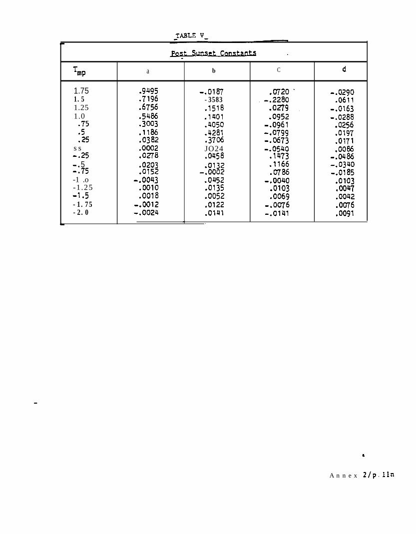
3.5 N o c t u r n a l varFatoo o f skywave f i e l d s t r e n g t h
Hourly median sk,ywave f ie ld s trengths vary dur ing the n ight and ats u n r i s e aad s u n s e t . The d iurnal factor is determined us ing the t ime o f day atthe midpo int o f the path between the s i te o f the iater fer lng s tat ioa and thepofnt a t w h i c h interference i s belw c a l c u l a t e d .
Diurnal factors are computed us ing the forsnula:
3f a a + bF + CF 2 + dF3 (6)
Where: D f r e p r e s e n t s t h e diurnal f a c t o r ,
F is t h e f r e q u e n c y i n MHz,
a , b , c , a n d d a r e c o n s t a n t s u s e d fnc a l c u l a t i n g t h e d i u r n a l f a c t o r s .

For the pre-sunrise and post -sunset per iods , the constants areobta ined from Figures SC and 5d. The ~olums labeled T p represent the numberof hours before and after sunrise ami Sunset at the pat F: midpoint. F i g u r e s Saa n d Sb d e p i c t t h e sky-wave d i u r n a l f a c t o r s tich r e s p e c t C O s u n r i s e a n d sunseta t t h e mfdpoint o f t h e transtission path.
Figures 5a and Sb or Formda 6 shal l be appl ied in decer;nininqf ie ld s trengths of s ignals of stations engaging in extended hours ofoperat ion . However, the ca lculat ions made according to Fomula 6 arec o n t r o l l i n g .
Diurnal factors greater than 1 will not be used in ca lculat ions ,and interpolation is to be used beeveen calculated values where necessary.
3.6 Sunrise and sunset time
T o f a c i l i t a t e t h e determination o f the L o c a l . time o f s u n r i s e a n dsunset , Figure 6 g i v e s t h e rimes f or various geographica l la t i tudes and foreach month of the year. The t ime is the loca l mer id ian t ime at the po intconcerned and should be converted to the appropriate standard time.

0.2 0.3 0.4 ' 0.5 0.6ilfura c3 la cn:,lnu zn Icqftud cl: o n d a (3.1
Niwrc C?raciides
I lZ43 rk p.-.-- . - ___-. __ ___ ______--. .-.. . . . . ---- - -- ----- -_-.- . - -_--.. -------9 .-. B.-e . ..--. ..-. .- -
- - - - -

FIGURE la -
A: S h o r t v e r t i c a l antenna
F i e l d strength a t a d i s t a n c e o f 1 k?n a s a f u n c t i o n o f e l e v a t i o nangle, fey d i f f e r e n t heights o f v e r t i c a l a n t e n n a assuminB a transmittexDower o f 1 klJ

. .

L-. *-.. .*-.
‘C. - ---
-w-e
i-=T
1---
t--- -----
‘4
i -..- _. . .
pt::.-
----
- -q.*-.I . . ..-a.. . . .
1 .-:-w---- -.e*
II 2 .v l
- - - - .arc) . _- .-.,..--�-.--. _.: - ,-L-P. .--
1
r--
. -. . ...*
7 ⌧ g �; : -- .�.,zr., -cm--.
. .I -3;. . .*. q ..- ,,:--i ☺ ,-.-*
.-.- . . -w.***_ I.-e
.-*- i - - * ----!
~ZLcq: 7Z.-+�--
---m*.,-,
i- .-- -�3
3 ._ . -.-.; *-*-*. . _-_ ; ___- j*- -d--- ..-,I
I
.-f-
�_ - *.I* 1 . ,I -�-------~- I-
I
-. ----w - --I- - -- } ____,
..w.
r ---- - .---. 1
.-__j_l
- . _ �_ 1 - -.r-TT -� ; .-.I _ -zy,., *--:- ._1 .
)�
�7 . *.�A
1 ,--..-. -.-f - -. ^ . - I - - . 2
;----* -
I - - - - --. -.. .
- : XIrzf: 1; :: . :.;:.-1 1 -: ;.- --~.lr-~~~-~~-I-.~-*_j: .-- I--;.--+
. ,-se .
II
I
._-.A--.
. -*e.---. . - . -
31 --,! i.::
I
.
-I
* *-..-*. . -.. - - -
- :
.- .--,�W . . . -
I-
; _
i
_ -.:, � . - _ ! .;; : : .: - .,: . -:.-g= q.-j--:� --..-e☺ =
. .: 1 . . . . - .
I
1 i. 1 /
I
.* I .
-.
_ .q::,--t .I z
. .-e-s. ..- .
I
i
1 -: . ._
-- ( -
..* _I
: -.. -1 -*
i -
I
*I-
. / : 1 :: . j i 1 _ j :.:;I 1 T i : : *asejF:Lj!!’
II I I
L
. . . -wi We ‘T”. T”‘__..__
.- . .- I-- *._ 1..-* . I
. . . . . I
I-
I
! I. 1 j ; j ! j !
;
; 1 -_;. i . j .-;.--J+
I ’I-’ .
L-’
: ; . I :. . . .
*.. / ; 1 : -;I: ; j -:; ) ;: . . 1 : .- :‘T ;.z-
L, I* . :
. . . . ..- I
I-.
I
‘; -1: / -; j . *: i’ / f I ; -.j:+-.-Ii. i
‘- Ie...-* ...* * - .*-.-. .
1 / .,I; 1
L- . . .,B*.. . . .
I
. .
I
I ;.:I
: :I ; j :-.T.: ( !- / . j yy :_:_j-J’
:-. m-e :- .*. I I
: . 1 i 1 ;. 1 i I. ,_i -1 :-f-i-,I
CUE. . .- *--- -
I: .I .A--- I- ,
. I*--
_---,.-.. . .- . . . . . I I I
‘----“: . ‘1---.- -*..- * *. . -
c_. -e-.
. -.-. I
-;I ___. 1. ; i ; j : . ; 1 ;. :.. / ;.* ( ‘1 +k-~,f
t.-z.:-Y/--: . -:-..,.. . ;~.TzK’! ‘.: ., ,’ I I
. : . - - ..-,--. :
- .. .. -7-s 3
. . . w ---.-:
I .:1 f ! . *- p..-e..
--X+Z. .:. : I -: ; ’ ,. . .--w-
. .*. --*. - *.. - . . . .. -. .- - - . . . - - . - I . I t 1
; ’ ; j ;;!.. ) . ;. ,: t-.--.+ -I
I I Ib*- *I- .- . . 1 -,. : _. + 1 - .I : i )
-*.. *. ,
+ . . - . . . . -s-*.- -. .:,-” . - - f -. -.- ( -:- .; .:. , . -. )
j.(f* 1; y&g5
+.- -- I .’ . ---4--w. . ,.,I- ‘. . .a -. i. . .* * *-.-I. . . . . , i .:1 . - . - . _ i :. I
i. . .*_ e..
I.*- . . . -: .*. . . ; I : I j 1I / I
; -..- d. * I . . .p-w*.. .- I- .-.-. *.. , _-
j ; 1 , 1 -.--j : ! . --.1 . ,.. . -
B.. ) -.-.- *..

'I II II! &I .Y Y n/,'Pl II ! I! ! A II ! 1
II /‘I ‘/I*
--I1 I I’ll I 1 II’ I
A n n e x 2/p. Lie

Eevation mangle . f(e)
(degres)0.d 0.13 A O.lSh 0.17X 0.1gA 0.21J
0 1 .ooo 1.000 1.000 1.000 1.000 1 .ooo1 1.000 1 .ooo 1 .ooo 1 .ooo 1 .ooo 1 .ooo23
t;;; 0,999 0.999 o-999 0.999 0.999
0:9970.998 0.998 0.998 0.998 0.998
4 0.997 0.997 0.997 0.997 0.9975 0.996 0.996 0.996 0.995 0.995 0.9956 0.994 0.954 0,994 0.993 0.993 0.9937 0.992 0.992 0.991 0.991 o-991 0.9908 0.989 0.989 0.988 0.988 0.9879 :*;i;10 o:g84
o.ga6* 0.983
i*;g 0385 oe985 0.984
0: 9790.982 0.981 0.980
11 0.980 0.980 0.978 0.977 0.97612 0.976 0.976 0.975 0.974 0.973 0.97113 0.972 ' 0.972 0.971 0.96914 0,968 0.967 0.966 0.965
kg:
15 . 0.963 0.962 0.961 0.959 01958
;*;i;
ok616 oa58 0.957 0.956 0.954 0.952 0.95017 0.953 0.952 0.948 0.945 _ .-18 0.947
f1 0.946
:*;:i0.942 0.940
;*w;
19 0.941 0.940 o&8 0.935 0.933 0:93020 0,935 0.933 0.931 0.929 0.926 0.92322 0.922 0.920 0.917 0.914 0.911 .- -- 0.90724 0.907 0.905 0.902 0.898 0.894 0.89026 0.892 0.889 0.885 0.882 0.877 0.87228 0.815
30 0.857 i-2: :*8":;
0.864
;*g:
0.852
0.84432 0.838 0:830 0.824 0:81i %::34 0.819
p&z
0:7930.809 0.803 0.796 0:789
36 :*;;i 0.788 0.781 0.7663840 0:753
0.771 0.765 0.758k?;;:
0.7420.748 0.742 0,735 0:726 0.717
42 0.730 0.724 0.718 0.7lO 0.702 0.69244 0.705 0.700 0.693 0.676 0.66646 0.680 0.674 0.667
2;;
0:6330.650 0.639
48 0.654 0.648 0.641 0.623 0.612SO 0.628 0.621 0.6l4 0.606 0.596 0.585
-52 0.600 OS94 0.587 0.578 0.568 0.55754 0.572 0.565 0.559 0.550 0.540 0.52956 0.544 0.537 0.530 0.521 0.512 0.50158
:*%55 .0.508 0.501 0.493 0.483 0.472
60 0.479 0.472 0.463 0.454 0.443

Eevation ea n g l e f(e) *
(degrees) r0.232 0.25 h
r0.27 A 0.29 A 0,311 h o.35h
0 1 .ooo 1.000 7 .ooo 1 .ooo 1.000 1.0001 1 .ooo 1 .ooo 1 .ooo 1 .ooo 1 .ooo 1.0002 0.999 0 0999 0,999 0.999 0.999 0.999
z :*;;Y ;*w; * "0-w; 0.998 0.996 :*:g 0.997 0.995
5 0:995 0:ggs 0:994 0.994 0:9936 0.992:*;i;
0.991 0.991 0.990 "0'9998;7 0.990 0.9888 0.987 0:906 0.985
;*g: 0.987 o:g85o-983 '0.980
9 0.983 9.932 0.981 0380 0.978 0.97570 0.979 0.978 0.977 0.975 0.973 0.96911 0.975 0,973 :*;:6' "o*;;: 0.968 ,-- 0.96312 0.970 0.968 0.962 0.955
.13 0.965 0.963 0:961 - o:gsB 0.955 0.94914 ii-;;; 0.957 0.955 0.952 0.948 o.g4115
0:9470.951 -0.948 0.945 0.941 0,932
16 0.944 0.941 0.937 0.933 -0.92417 0.941 0.937 0.934 0.930 0.925 _ 0.91418 0.934 0.930 0.926 0.921 0.916 0.904
19 0.926 0.922 .0,918 0.91320 0.919 0.914 '0.909 0.904 %;S :*8898;22 0.902 0.897 0.891 0.885 :- 0:85124 0.885 0.879 0.872 0.865 c$;; 0.837-26 0.866 0.859 0.852 0.843 0:833 0.81128 0.846 0.833 0.830 0.820 0.809 0.785
0.825 0.816 0.807 0.784 .30 0.797 0.768
32 0.803 0.79434 0.780 0.770 :@;:; if;:; 0.7590.732 "o*;z36 0.756 0.746 01734 0:721 0.705 0:6713840
i?;z
0:681
x;:
0:668
E% 0.694
0: 6540.667
zi;: 0.6420.612
42 0.639 0:621 0.58244 0.654 0.641 0.627 0.611 0.593 0.55246 0.628 0.600 0.58348 0.600 2;
015590.572 0.555 :*:;z 00~~;~
so 0.573 0.544 0.527 0:507 0:46552 0.545 0.531 0.516 0.498 0.479 0.43654 O.Sl7 0.503 0.487 0.470 0.451 0.40856 0.488 0.474 0.459 0.442 0.423 0.38158 0.460 0.446 0.431 0.414 0.395 0.35460 0.431 0.4l8 0.403 0.387 0.368 0.328
1 L A
Annex 2/p. lb

tLcvatzonan@ c
(degrees)0.4oJ1
0123456789
1011121314151617181920222426283032343638404244464850525456586062646668707274767880
When the negative sign (-) appears in the Table, it signifies o~Ythe existence of a secondary lobe havfng the opposite phase from the mainlobe fn the vertical radiation Fatter% In order to perform thecahdatlon, ignore the negative (-) and use only the absolute vahe of f(e)from thr Table.
1 .ooo1 .ooo0.998o-9970.9940.9810.9060.9320.9760.9700.9630.9550.9470.936
0.9290.9180.9080.8970.8850.8730.8600.8330.8050.7760.7450.714
2:;0:6170.584
:*go:4880.4570.4270,3970.3690.3410.3160.2890.265
1.0001 .OQO0.9980.9960.9920.9880.9830.9770.9700.9630.9540.9450,9340.9230.9120.8990.8860.8730.690.8440.8280.7960.7630.728
0 . 6 9 20.6550.6190.5820.54 j0.5090.4730.4380.405
:*:'I:.0:3110.2830.2570.2320.2080.186
1.0000.9990.9980.9960.9900.9860.9790.9710.9820.9530.9420.9300.9170.9030.889
%0:8400.823
- 0.8040.7850.746
z:;0:6210.5770.5340.4920.4500.4090.3700.3320.2960.2620.2300.2010.1740.1490.1260.1060.087
1.0000.9990.997
z:9”-0:9830.9760.967'0.9570.9450.9330.9190.905
t 0.8890.8720.855.0.8360.8170.7970.7760.7550.7100.6660.6180.5700.5220.4750.428
0.3830.340
- 0.2980.2580.2210.1810.1350,1260.0990.0760.0550.0370.0270.008
-0.003-0.011-0.017-0.022-0.025AI.025-0.026a.024-0,022
1.0000.999Q-9970.993 -0.9880.9810.9720.9620.9510.9380.9240.909O-8930.8760.8570.8370.8160.795
gt;0:7260.6670.6250.5740.5220.4700.4190.3690.3210.2760.2310.1900.1620.1170.0850.0560.031 '.0.009
-0.010-0.026-0.039-0.049AI.056-0.062-0.064-0.065-0.064a.061-0.056a.051-0,044
- 1.0000.9990.996
:*;z;:;g
0:9410.9240.9040.8820.8590.8340.8070.7780.7480.7170.6840.6510.6170.5820.5100.4360.3630.2900.2190.1510.0850.025a.031-0.083-0.129-0.170Co.205-0.235-0.259-0.278-0.291-0.3'004.304-0.304
2:;:-0:281-0.267-0.250-0.231-0.210-0.138-0.163-0.138
0.45 a
f(e)
0.528x 0.55x 0.625A

3. . .. ..I

TABLE III - Skywave field strength vs distance (from 100 to 10,000 km) . .
for a characteristic field strength of 100 u&m at L .km.
d(b) Fc (d&l -50%
100 179.11150 117.18200 92.06250 77.54300 68.82 \
350 62.06400 57.08450 52.86500 49.65 .550 46.78600 44.36650 41.95700 39.54750 36.81800 34.40850 32.30900 29.89950 27.63LOO0 25.541050 23%1100 21.841150 19.911200 18.301250 16.70 _1300 15.321350 13.971400 L2.711450 11.551500 10 .so1550 9.53L600 8.571650 7.721700 6.981750 6.34L800 5.301850 5.32L900 4.491950 4.492000 4.L42100 3.612200 3.L82300 2.792400 2.552500 2.262600 2.032700 1.852800 1.692900 L.55
d (km)
300031003200330034003500360037003800390040004100420043004400450046004700.480049005000.5100-52005300-5400--5500560057005800590060006200640066006800700072007400760078008000820084008600880090009200940096009800LOOOO
Fe (&I50%
1.431.331.231.151.071.000.940.880.830.7901.750.710.670.640.610.580.550.53 -0.510.48 -0.460.450.43. --_0.41 -0.40 .- s.0.38 -.0.37. '-. . . ._. .0.360.340.330.320.30
. 0.28 .0.270.250.240.230.220.210.200.190.180.17
. 0.170.160.150.150.140.14
ii-:3.llj

.-

0.x
ir M/e.- Fuclofs given in lefms of hour wifh fespec: to 1
[ sunset ut mid-pcinl of tfansmissl’on path. . 1,a.. ,I’. .e ,..-,
-. .5 .5 .7 .3 .3 LG 1.1 1.2 L.3 1.c 1.5 1rr=cuenc*,~ ir: Et!!=
-.. 9.’ - - -\ -c).- . . . . . z.\ LIZ. -. -

TmP a b C d
- 2 1.3084 do83 0.0155 .0144-1.75 I.3165 -.4g1g .6011 0.1884-1 .5 1 .omg .0296 .1488 -.0452-1.25 07773 .375i -.ry1 00736-1 .6230 .I547 2654 -.I006a.75 -3718 .1178 03632 0.1172
1125 5 .2027 .21 jl -.2560 An37 07269 A167 0.1413 -2577S3 .I504 -. 2325 .5374 -. 1729+.25 s A057 a.2092 .4148 -. 1239+S .0642 0.1295 02583 -a99+J5 .0446 9.1002 .17j4 -.0405
+l .0148 -.0135 .0462 .OOlO
km’ex 2 / p llrn
Tw a b C d
1.75 09495 -.ow Jr720 -.02901.5 07196 -3583
*. -.2280 .0611
1.25 A756 ~518 AZ79 . 0.01631.0 3486 .1401 .0952 0.0288075 03003 .4OjO -.Og61 ~0256.5 .1106 .4281 -0799 a197.25 .0382 .3706 -.06?3 .017l
s s .0002 JO24 -.0540 [email protected] .0278 .0458 .14?3 -.0486-0 5 .0203 .0132 .1166 0.03409.75 .0152 -.0002 x786 -.0185-1 .o TOO43 .0452 -.0040 .0103-1 .25 .OOlO .0135 .0103 A047-1.5 .0018 .0052 .0069 .0042-1.75 -.0012 .0122 0.0076 .00?6-2.0 ~0024 .0141 9.0141 .oogt
* -
A n n e x 2/p. lh

-_ _15 -. (4 17 19 19 20 21 22
Local time at reflection point Chours)
An-flex 2/p. 110

12
e
Broadcasting Standards
4 . 1 Seoatatlon of Channels
frequenciesThis Agreement 1s based on a channel spac ing o f 13 kHz and carr ierwhich are integra l mult ip les o f LO kHz, beg inning at 540 kHz.
Class o f e m l s s l o nJ 34.w
This Agreement 1s based upon double-sideband amplitude Podulationw i t h f u l l c a r r i e r A3E.
Classes o f emiss ion other than UE, f o r i n s t a n c e t o accotnmodatestereophonic systems, could a lso be used on condi t ion that the energy leve lo u t s i d e t h e n e c e s s a r y bandtidth d o e s n o t e x c e e d t h a t norsally expected in x3Eemiss ion and that the emlss lon 1s rece ivable by convent ional receivers employinge n v e l o p e d e t e c t o r s w i t h o u t i n c r e a s i n g a p p r e c i a b l y t h e l e v e l o f d i s t o r t i o n .
4 .3 Bandwidth o f e m l s s l o n
This Agreement assumes a necessary bandwidth of 10 kHz, for t;hichonly a 5 ‘Cyz audio bandwidth can be obtained.
3ote: Lt i s n o t e d t h a t s o m e s t a t i o n s h a v e s u c c e s s f u l l y employed tider baadtrFdthsystems hating occJpled bandwidths of the order of 20 kHz without adversee f f e c t s .
4.3.1 Frequency tolerance: f20 Hz. However, both Administrationsrecognize chat it is des i rab le to implement the to lerance o f f10 Hz Fnaccordance with the ITU Radio Regulat ions (1982) .
4 .4 Station power
4 . 4 . 1 Class A
- The power o f any Class A s tat ion exceeding 100 kW day /50 kW nightshal l not be increased .
- The power of any Class A station not exceeding 100 kW day/SO kWnight may be increased but shal l not exceed those va lues .
- Any new Class A station shall have a power not exceedingL O O kW day / 50 Kg sight.
4 . 4 . 2 Class 3
- T h e maximum s t a t l o n power s h a l l b e 5C k;J.
4.4.3 Cbss c
- T h e maximum s t a t i o n p o w e r s h a l l b e 1 kU.

13 -
6.5 Skpvave i n t e r f e r e n c e c~culations
T h e v a l u e s o f i n t e r f e r i n g skyMve signals shirll b e c a l c u l a t e d ou t h eb a s i s o f 10% o f t h e tie, i n t h e manner p r e s c r i b e d i n s e c t i o n 3 . 6 .
4 . 6 Nominal usable f leld strength.
4.6.1 ch66 A 6tatiOU (1)-----------e-
Gr ouadvave
Daytime: co-channel 100 pV/m and adjacent channel 500 pV/m
Nighttime: 500 jlV/m
Skyvave
Nightime: 5 0 0 pV/m, 5OZ o f t h e t i m e
4 . 6 . 2 CLass B s t a t i o n ( 2 )- - - - - - - - - - - - - - - -
Groundwave
Daytime: 500 pvlm
N i g h t t i m e : 2 5 0 0 pV/m
4 . 6 . 3 Class C s tat ion (2)- - P - - B - - - - - -
Groundwave
Daytime: 500 JlV/m
Nighttime: 4000 pV/m
N o t e ( 1 ) : The nighttime contours, groundwave o r skyvave w h i c h e v e r is f u r t h e r
a r e t o b e p r o t e c t e d i n t h e c a s e o f c l a s s A s t a t i o n s .
Xote ( 2 ) : The protected contour dur ing n ightt ime operat ion for c lass B aad Cstat ions shal l be the h igher o f the grounduave contour in 4 .6 .2 and 4.6.3r e s p e c t i v e l y , or the groundwave coatour corresponding to the usable f i e ld
s t r e n g t h o f t h e s t a t i o n a s s e t f o r t h Fn 4 . 7 .

14
4.7 U s e o f t h e r o o t sum square (RSS) method to determine the usablefield strength resulting from the weighted interfering signals L/
4 . 7 . 1 GeneralThe overall usable fleld strength E due to two or more individual
i n t e r f e r e n c e c o n t r i b u t i o n s 1s c a l c u l a t e d o n a n #SS basis, u s l n g t h e e x p r e s s i o n :
E\/
2(alEI) i (a2E2)2 +.,.. (aiRi) 2 (1)
U=
here:
El 1s the f i e ld s trength o f the lth interfering transmitter (in ~v/s)
ai 1s t h e r a d i o - f r e q u e n c y p r o t e c t o n r a t i o associated tith t h e lthi n t e r f e r i n g transmitter, expressed as a numerica l rat io o f f i e ldstrengths .
4.7.2.1 50% exclusion nrlnclnle
T h e 5 0 % elCCh6iOU p r i n c i p l e a l l o w s a s i g n i f i c a n t r e d u c t i o n ln t h enumber of calculations l
4.7.2.2 *.
A c c o r d i n g t o t h i s p r i n c i p l e , the va lues o f the indiv idual usablef ie ld s trength contr ibut ions are arranged in descending order o f magnitude . -If the second value 1s less than 50% of the first value, the second value andal l subsequent va lues are neg lec ted . Otbertise an RSS va lue is ca l cu lated forthe f i rs t and second va lues . The calculated RSS value Fs then compared withthe third value in the same manner by vhlch the first value zas compared tothe second and a nev RSS va lue i s ca l cu lated l f required . The process i scontinued until the next value to be compared 1s less than 50% of the lastcalculated RSS value. At that po lnt the last ca lcu lated RSS value 1s ._c o n s i d e r e d t o b e t h e u s a b l e f i e l d s t r e n g t h EU.
4 . 7 . 2 . 3 Except as provided in sect ion 4 .7 .2 .4 , if the contr ibut ion o f anew stat ion 1s greater than the smal lest va lue prev ious ly considered incalculat ing the RSS value o f ass ignments in the Plan, the contr ibut ion o f thenew stat ion adverse ly a f fec ts ass ignments ln conformity with this Agreementeven if it 1s l ess than 50% o f the RSS va lue . Hoveve r , the new contributiondoes not adverse ly a f fec t assignments in conformity with th is Agreement i f theRSS value determined by inserting the contribution of the new station in thelist o f c o n t r i b u t o r s is s m a l l e r t h a n t h e n o m i n a l u s a b l e f i e l d s t r e n g t h Znom.
4 . 7 . 2 . 4 The contr ibut ion o f a s tat ion engaging in extended Sours ofoperat ion under Art i c le VI o f th is Agreement shall not b2 taken into accountin t h e c a l c u l a t i o n o f t h e EU-
l/ i n d u e t i m e ,Zgreement,
i n a c c o r d a n t e tith Paragraph 5 .2 o f A r t i c l e V of t h e preseatconsFderatlon should be g i v e n t o t h e c o n t r i b u t i o n s o f stacior= o f
other countr ies in Region 2 .

15
4 . 8 Channel protect ion rat ios (des i red to undesired)
4.8.1 Co-channel protection ratio
The co -channel protect ion ratlo 1s 2O:l
4 . 8 . 2 nd jacent channel protection ratio
T h e p r o t e c t i o n r a t i o f o r t h e f l r s t a d j a c e n t c h a n n e l i s L:L
The protect ion rat io for the second ad jacent channel 1s 130
4.8.3 Syachroalzed networks
In addition to the standards specif ied in ihl6 Agreement, thefollofting addlcional s tandards apply to synchronized networks .
for the purpose of determining interference caused by synchronizedae two rks , the fo l lowing procedure shal l be applLed. I f any two transmitters
are less than 400 b apart , the network shal l be t reated as a sing&e ent i ty ,the va lue o f the compos i te s ignal beiug determined by the quadrat i c addftlouo f t h e i n t e r f e r i n g s i g n a l s fran a l l t h e i n d i v i d u a l traasmitters l a t h e .ae twork. I f the d is tances between a l l the t ransmitters are equal to orgreater than 400 km, the network shall be treated as a set of individualtransmitters.
For the purpose of determining skywave laterf ereace received byany one member of a network, the value of the interference caused by the otherelements of the network shall be determined by the quadratic addition of theinterfering signals from all of those elements. In any case, where groundwaveI n t e r f e r e n c e Is a f a c t o r lt s h a l l b e t a k e n into a c c o u n t .
The co -channel protect ion rat io betweea s tat ions be longing to asynchronized network is 221
4.9 Application of protection criteria
4 . 9 . 1 Value of protected contours
Within the nat ional boundary o f a country , the protected coatour .shall be determined by using the appropriate value of nominal usable f ieldstrength, or as otherwise determined Fn Note 2 to paragraph 4.6 for class Band C stations.
4 . 9 . 2 Co-channel protect Fan L/
4.9.2.1 D a y t i m e orotectlton o f aLI c l a s s e s o f s t a t i o n s
During the daythe the grouadwave contour of class A, B and Cstations shall be protected against groundwave fnterference- The protected
L/See t h e matrix l n S e c t i o n 5 o f Appendix 5 t o Annex 2 .

contour is the groundwave contour Corresponding to the value of the nominalusab le f i e l d sttength- The maxisum per;Plssible interfering field 6treagth att h e p r o t e c t e d ContouI: 16 t h e iralue o f t h e n o m i n a l u s a b l e f i e l d s t r e n g t hdivided by the protection ratio. The effect of e a c h lnterferlng s i g n a l sha l lbe eva luated separately- That is, ~otvirhstanding t h e p r e s e n c e o finterference from other stations, modi5Fcatlons o r p r o p o s e d asslgznents sustprotect a value cor:esponClns to the nominal usable f ie ld s trength . ;r’here thep r o t e c t e d contou: uould ex:cnd beyoad the boundary of the country in which thestatfon i s l o c a t e d , t h e sa.uiaum pexznissible i n t e r f e r i n g f i e l d s t r e n g t h a t theb o u n d a r y i s t h e c a l c u l a t e d f i e ld s t r e n g t h of t h e p r o t e c t e d station aloe t h eboundary divided by the protection ratio.
4 . 9 . 2 . 2 Nighttime protectfon of Class h stations
The groundwave contour or the skyave contour 50% o f the tise,whichever Ls far ther from the site o f the protec ted Class A statlou, shal l bep r o t e c t e d agafnst skywave a n d p o s s i b l e groundwave i n t e r f e r e n c e d u r i n g t h enighttime.
The value of the protecccd contour corresponds to the nominalu s a b l e f i e l d s t r e n g t h . T h e saxlmum p e r m i s s i b l e i n t e r f e r i n g f i e l d s t r e n g t h atthe protected coatour is the value of the nominal usable field strengthd t v l d e d b y t h e p r o t e c t l o a r a t i o . However, f o r C l a s s A s t a t i o n s notified a f t e rthe date o f signing of this Agreement, the value o f the protected contour .corresponds to the nominal usable f i e ld s trength or the usable f ie ld s trength ,whichever i s greater .
T h e e f f e c t o f e a c h i n t e r f e r i n g signal s h a l l b e e v a l u a t e dseparate ly . Where the protected coatour would extend beyond the boundary ofthe country in which the station is located, the maximum pemisslbleinterfering f i e ld s trength at the boundary i s t h e c a l c u l a t e d f i e l d s t r e n g t h o fthe protected station along the boundary divided by the protection ratio. Twos p e c i a l c a s e s o f a p p l y i n g t h i s p r i n c i p l e a r e a s f o l l o w s :
(a) Where the primary service area extends beyond the boundary,the protected contour is ca lculated uslag the groundwave f ie ld s trength , andthe skyvave contour i s protected outs ide the pr imary service area .
(b ) In cases where the protected skywave contour would extendbeyond the boundary, the groundwave contour shall also be protected.
4 . 9 . 2 . 3 Nightt ime DrotectFon o f c lass B and C s tat ions
Duiicg t h e nighttime, the groundwave contour or’ class 3 and Cs tat ions wi l l be protected against skywave and poss ib le groundwavei n t e r f e r e n c e . The protected contour 1s the groundwave coatour correspoadiagto the value of the greater of the nominal usable f ield strength or the usablefield strength rcsr?lting from the Plan o f Annex 1 to this Agreement asdetermined at the site o f the protec ted s tat ion in accordance vlth 5.7. The~xkmzi pemlssible Faterfering f i e l d s t r e n g t h c a l c u l a t e d a t t h e site o f t h eprotected station in accordance l dth 4.7 shall not be exceeded at theprotected contour qhere the protected contour Is located with in the boundaryof t h e c o u n t r y in w h i c h t h e statI. i s l o c a t e d . IThere the protected contourWouLd extend beyond the boundary ol t h e c o u n t r y in w h i c h t h e station FSl o c a t e d , the protected contour shal l f o l low that part o f the boundary and have

a value as cticulated at the border. Where the maxburp pedsslblefaterfering field strength is already exceeded at the protected contour by aaexisting station, any propo?al for a change to that edsting statloa shall aotcause an iacrease in the interfering field strength at that portion of the .protect& coutour.
1.9.2.4 Modification of assigruPents
If a station of one Administration causes laterfereace to as tatioa of the other Admialstratioa and such inter fereace i s petmltted inaccordance tith the terms of this Agreement, then in the event of amodification belag proposed to the assignment correspondlag to the formerstation, it will not be necessary to protect the assignment corresponding tothe la t ter s tat ion beyond the leve l prov ided be fore the proposed modiflcatlon.
4.9.3 Adjacent channel protection A/
During the daytime and aighttlme, the groundwave contour of classA, B and C s tat ions shal l be protected against grounduave intc ference . Theprotected contour is the groundwave coatour corresponding to the value of thenominal usable f ield strength determined as follows:
-for daytime protectioa of class A stations, the value specifiedin 1.6.1 for adjacent chanael daytime groundwave;
.
-for nighttime protection of class A statfaas, the value specifiedla 4 .6 .1 for nlghttFme groundvave ;
- for dayt ime and n ightt ime protect lou o f c lass B statioas, theva lue specified i n 4 .62 f o r d a y t i m e g r o u n d w a v e ;
-for daytime and nlghttfme protection of class C stations, the . .value specified in 4.6.3 for daytime groundwave;
The maximum permissible interfering field strength at theprotected contour i s the value o f the nominal usable f i e ld s trength d iv ided byt h e protection r a t i o . The effect of each lnterferlag signal shall beevaluated separately.
Where the protected contour would extend beyond the boundary ofthe country in which the s tat ion i s located , the maximum permissLbleinterfering f ie ld strength at the boundary is the ca lcu lated f ie ld s trength ofthe protec:ed assfgnment along the boundary divided by the protection ratlo.
I f a s tat ion o f one Administrat ion causes inter ference to astation of the other Administration and such interference is persitted laaccordance vith the terms of this Agreement, then ln the event of amodification being proposed to the assignment corresponding to the formerstation, it vi11 not be necessary to protect the assignment correspondlug tothe lat ter stat ion beyond the l eve l prov ided be fore the proposed modification*
L/ See the matrix in sect ion 5 o f Appendix 5 to Annex 2 .

18
4 . 9 . 4 Protect ion outs ide nat ional boundar ies
4 . 9 . 4 . 1 No station has the rlght to be protected beyond the boundary oft h e c o u n t r y in vhich t h e station 1s established.
4.9 .4 .2 No broadcast ing s tat ion shal l be ass igned a nominal f requency titsa separation of 10 o r 2 0 kYz from t h a tthe 25 ,000 uV/m contours over lap .
o f a s t a t i o n in t h e o t h e r country ff
4.9.4.3 In a d d l t l o n t o t h e coaditions described in 4 . 9 . 4 . 2 , vhen t h eprotected contour would extend beyoad the boundary OF the country in which thestation 1s l o c a t e d , i ts ass lgnmenc shal l be protec ted ln accordance tith 4.9 .2a n d 4 . 9 . 3 .
4.9 .4 .4 F o r p r o t e c t i o n puqoses, the boundary of a country shall be deemedt o e n c o m p a s s oaly its l a n d a r e a , including fslands.

19
R a d i a t i o n C h a r a c t e r i s t i c s o f TransmittLng Antennas
5. In carrying out the calculatfms indicated ia Chapters 2 and 3,the follotiag shal l be taken into account :
5.1 Omnidirectional antennas
F i g u r e 1 o f C h a p t e r 3 s h o o s t h e c h a r a c t e r i s t i c f i e l d streugth o f asisple vert i ca l antenna as a funct ion o f its length and o f the radius o f theground sys ten.
I t i s c l e a r t h a t t h e characteristic f i e l d s t r e n g t h i n c r e a s e s a sthe loss in the gromd system 1s reduced to zero and as the antenna height 1sincreased up to 0.625 wavelengths.
The increased character is t i c field strength for antenna lengths upto 0.625 vavelengths 1s obtained at the expense of reducing radiation at highangles as shown graphically ln Figure la and numerically in Table II ofChapter 3.
5.2 Considerations of the radiation patterns of directional antennas .
The procedures for calculating theoretical, expanded and augmented(modified expanded) directional antenna patterns are given in Appendix 3.
5 .3 Top-loaded and sectionalized antennas
5 . 3 . 1 Calculation procedures are given in Appendices 4 & 6.
5 . 3 . 2 Hany stations employ top-loaded or sectionalized towers, eitherb e c a u s e o f s p a c e l i m i t a t i o n s o r t o v a r y t h e r a d i a t i o n c h a r a c t e r i s t i c s fromthose of a simple vertical antenna. This is done to achieve desired coverageor t o r e d u c e fnterference.
5 . 3 . 3 . The Adainistratlon us ing top - loaded or sec t ional ized antennasshall supply information concerning the tower structure of the antennas.Normal ly , one o f the equations in Appendices 4 & 6 shal l be employed todetermine the vertical radiation characteristics of the ante&as. Other
equations may also be proposed by an Administration and shall be used i.ndetermining the vertical radiation characterfstlcs of the antennas of thatAdminFstration, subject to the agreement o f the o ther Adminlstration-

APPENDLX 1
(to annex 2)
J&D l':iE USITED STATES OF .LXE3ICx.
Appendix l/p.1

\ -I

IiiII
i.1
I

(to Annex 2)
FIELD-STRENGTH Ct'VES F O R CROUhDWA~ PROPAGATXOX
Appendix 2/p. 1

0.0001
I m cwm10
K;iMETERS FROM ANTENNA1000
. #
isc!'aI
i@i3C
IG"
i’ ‘I’, 15
iI :/
i
,! /
/
10
.yi 8
//
: 7
/6
.5\
\4
\
3
\
2
\
lC. .
\
1
\0'. .
O.-

10 1000
l&MEERS FROM ANTENNA
GFuwi2

a. -- -.-. . .
- -
:
I3 10 :‘ia ’ I10 1000
I I,,10
K&METERS FROM AElTEPJNA
GRAPH 3

-- -:b 100
KILOMETERS FROM ANTENNA
GRAPH 4 .

0.1
0.07
8.8s034
O.OJ
0.02
0.m
0.002
0.001 :
0.0001 1 ,, . . . I .,,a . , , .I I I IIIII
AI 11 IIII I I
1 3 ws8 Ta aw coQs88 m Loo0 do0 4808%
10
JiiOMETERS FROM ANTENNA1000
-5
-4
‘ 3
‘ 2
\1.
\1
\
\
0
0
GRAPH 5 .

._~ _--,-. . . . ..-- --
. . . . . --..-w .--m. . -
. _ __ . .-_ ..e . -.
_-_-.- . . we . . -
KILOMETERS FROM ANTENNA
GRAPH6 .

-4
-3
-.
Y
11
kl.5
\ 0.:
KItOMEi'ERS FROM ANTENNA
GRAPH7

O.OTa.os0.U0.03
0.02
0.07
0.001 j
0.007
0.005
0.W
0.001
a. JO2
7_
0.mi
0.w 1
a.Joo5
0.M
0.1002 1
10 100 1000
KILOMETERS FROM ANTE?dNA
GRAPH 8

- 1
A0.f\ O.-
KILOMETERS FROM ANTENNA
GRAPH9 .

0.0
GRAPH 10 .

I
-..
g.y .--- - -1 _ -.. .: _ .I
-:..: ‘::I. . . .
.--f
. .
.* .
9 _
3
-. . ; :-“.*. .
.
. . . . . ;j -i. I
.
. . . . . . . . --
----we. .
io 100 1000
KILOMETERS FROM ANTENNAGRAPH 11

I0.0001I t i I III20 1D 4k A 70
&j J&uocl10
K;:OMETERS FROM ANTENNAlooa
GRAPH 12 .

KILOMETERS FROM ANTEFINA
GRAPH 13 .

0.67
a.05
0.01
0.01
0.02
0.01
44
0.007
0.003
0.001 0.10.W
0.902
1
GRAPH 14

. . -. --. . . . ..- -
-.- ;. .
.- -.-.
. . -..... - .a....
._ . .
----
--
10 100 loo0
KILOMETERS FROM ANTENNA
GRAPH 15 .

KILOMETERS FROM ANTENNA

0.1 -
a.07
usa.01
am
am
a.01 -
0.w
a.oasa.001
8.w’
o.wz
a.001 -.-
0.3oQ7
Q.wwa.*#maa
a.waz
0.ooo1-
10
iJlMETERS FROM ANTENNA
GRAPH 17

10 100
KlLOMtrERS FROM ANTENNA
GRAPH 18 ..

10
I&METERSFROMANTENNA1000
GRAPti19.

/ --
Calculation of dirtctiond a3ttnnb F:teFnsm
TSe th;oretical directionel antenna raMAA;ation patterr: is calculated
by mgg~'.s of the follo,ving l quaZion, vhich SUE the field strensi! frcn; es&
element Itover) in the array :.+e) = x7 z” F. f;
I d i=l 1 * (5) /Yi + si cosecos~~~i - ~)I
vhcre :
fi(j) = ~0s (Gi sin 6) - COSGi(2)
u - cosGi ) case.- .
z+o,e) : theoreTica inverse distk?ce field stren?h a', one kiromtrein nV/m for the g i v e n azimuth and elevatron;
KL
n
: multiplying constent in S/m which deternines the patternsize (see paragraph 2.5 below for derivation of E$ 1;
.. number of elements in the dlrectionti array;
i : deDotes the ith elment in the array;
FA .1.
. 7 field strength due to the ith. ratio of the theoreticaelement in the array relative to the theoretical fieldstrength due to the reference element;
0
G.1
5
(POi
... vertical e l e v a t i o n a&e, i n degees,
measured irom the
horizontal plume;
.. ra:io o f ver t i ca l to horlzontel plane field strengthredieted by the itr: eleaent ai elevetion angle 0;
.. electrical heigh’c of the ith element in degree9 ;.
.. eltctricd spacing of the it5 eleme=!t fron the reference
in degrees ;
- element: orientation of the ith elc=nez”.= from the refe:enc-
(with respect to True North), in degrees;
.. arinuth(vith resFct to True north ) in degrees;
: electrical phase angle of field strensh du-* to the ith.
eltacnt (with respect to the refererrce ekmcnt), rn*de~eeS-

EquAtions (1) aad (2) assume that :
- the cu;rrent digtributioa in the elemurts is sinusoidal,
- there ut BO 10~~s in the clewits or in the gmxd,._e
- tpc a n t e n n a elements Ut base-fed, aad
- the distance to.thc CorPputatioa pint is large itr rclatioa $0 the
rize of the array.
?
2 . 1
Detenination of values and constants _
Ptt&ination of the multiolyins constant K for WI array
The mu&plying constszlt IL for the loss-free case may be computed by.integrating the povcr flov over the hemisphere, deriving an r.m.s. field strengthaad. comparing the result vith the cue vhere the paver is radiated uniformly LP*all directions over the hetisphere.
Thus :
K - 5 -rF‘h
vhere : l
IL :
E
�0
.
8
P ..
% :
mmaa.
n&lors titiplying constant (mV/m at 1 km);
reference level for uniform radiation over a hemisphere,equal to 2CgS d/m at lkm for 1 W.
-t-A i n p u t paver (kV);
root Peaa squazt xwiiation pattera over thehtiehere which may be obtained by integratinge(9) at each elevation mgle OYC~ thehtisphere. The integration ca be made using thetrapezoidal method of approximatipn, as follovs :
=h =(3)
where :
'A : interval, in degrees, bctveen equally-speced sa+.ingpoints at differect elevation angles 6; /'
m a. aa integer from 1 to N, which gives the elevation angle e
in degrees vhep multiplied by A, i.e. 8 = d;
N90
. one less than the number of internals (N = 11 - 1);.
de) : root mean square rtiietion pattern given bykpation (1) vitfl K
equal to 1 at the specified l lcvatioq angle 9 (the valueof 8 is 0 in tnc first term of equation 3 and mA rn thesecoad term); e(6) is computed using equation &.
. Appendix 3/p.2

where:
v, :
s, :
Jo (S, cos 8) :
denotes the ith element:denotes the jth elemcnr;number of cfcmtno in the array:
difference in phase mgles of the field sttenkhs from the ith and jth elements in the amay;
angular spacing between the ith and jth &menu in the arny:
the Bessel function of the fine kind and zero order of the apparent spacing ktwccn the ithand jth clcmcnu. In equation (1). S9 is in radians. However when special tables of Bcssclfunctions giving the argument in degrees ‘arc used, the values of &, should then be indegrees.
2.2 Relationship brrwecn field srrengrh and antenna mrrenr
The field strength resulting from a current flowing in a veniul antenna clement is:
&‘IR,I [cos (C sin 8) - ~0s G lx 1O,
s 2?uCOsemvjm ’
where:
E : field strength in mV/m:
R, : rcsistivicy of free space (R, - 120x ohms):
I : current at the cumnt maximum. in 8mpcrcs ‘;
G: ekuriul height of the eiement, in degrees;
r: distinct from the antenna, in met=:
9: venial clewion angle. in dcgm.
henc::
At one kilometrc and in the horizontal plane (9 - 0’):
E-1201cl(1 -coi G) x 10’
2mmmV/m (6)
E - 6Of(l - cos G) mV/m (7)
I f is the cumnt 11 the maximum of the sinusoidal distribution. If the elmrial height of the clement is las than 96.. thebase cuncnc will k ks than I.
Appendix 3/p l 3

2.3 bteminathm of npO-lo66 Current at Current m%imuLU
For a tower of uniform crs6-Section or for a 6ldlar type of
directional array clement, the-no-l-6 current at the Currrnt maldmm 1s:
Ii - KF, (8)
6 0 (1 - cosG$
Where:
I, : current at current maximum in amperes in the lch element:
K : no-loss mukiplying coastant computed as shown in paragraph
2.1 above;
The base current 16 given by Ii sinGi .
2.4 Array power lo66
Paver losses in a dfrectlonal antenna system are.of various types,
including ground losses, antenna coupling 106~~6, etc. The loss resistance .
for the array may be assumed to be inserted at the current maximum to allow
f Or all 1066eS. The power loss is:r.
pL - 1 % Ii 2(9)
Where: 1000 A =I
PL : total power loss in Mlovatts;
Ri : asetrmed 106s resistance in ohms (one ohm, unless otherwise
indicated) for the ith towet";
Ii : current at current maximum (or base current if the element is less
than 90 degrees in electrical height) for the ith tower.
* The loss resistance shall ln no vay exceed a value such that the value of
KL( see paragraph 2.5) differs by more than ten percent fran that dculated
for a resistance of one ohm.
Appendix Z/p.4

vhe=:
KL : mdtlplying eons cant after correction for the assumed
loss resistances
K : no-l066 multlplflng constant canputed in paragraph 2.1
above;
P : array input paver (kw)
2.6
2.7
PL : total paver 106s (b)
r.9.s. value of radiation to be notif ied for directional antennas
The radiation (Er for dlrectfonal antennas is detemined as follows:
E, - KL e(0) mV/m at 1 kilometre
Determination of expanded pattern values
vhe re :
The expanded pattern 1s determined as follW6:l/2
EEXp (6,8) - LO5 LET we,J2 + Q2 (11)
\EEXP (he> - expanded pattern radiation at a particular azimuth,@
and a particular elevation angle, 0;
ET (#he) - theoretical pattern radiation at a particular
azimuth, +, and a particular elevatim angle, 8;
Q = quadrature factor, canputed as :
Q = Q. g (0)
vhe re
Q, is the Q on the horizontal plane,
tk following three quantities:
10.0 ; 10 fi or
and Fs normally the greatest of
Annex 2/p:
Appendix 3/p -5

If the thctfid hef ght of the rhoeert twcr i6 14268 tbn or equal to
180 degrees, then: g(e) - f(o) for the chort66 tower.
If the electrical height of the 6hOrte6t tmer i6 gR6ter th6n 180
degrees, then:
where f(4) for the ehortest twer 16 used.
Note: In canparing the electrical height6 of the antenna towers to detersine
the ehortest twer, the total apparent height (as determined by current
dl6ttibutlon) is used for top-loaded and sectionalized towers.
2.0 Detennfnation of augmented (modified expanded) pattern values
The purpose of the augmented (modified expanded) pattern 16 to put one or
more “patches” un an expanded pattern. Each 'patch" 16 referred to a6 an
"augmentation". The augmentation may k positive (resulting is more radiation
than that of the expanded pattern) or negative (resulting in less radiation
that that of the expanded witern). In no case shall the augmentAti.On be 60
negative that the augmented (modified expanded) pattern radiation is below the
theoretical radiation pattern.
Spans of augmentation may uverlap. That is, an augmentation may itself
be au&ted by a subsequent augmentation. To en6ure that the calculations
are properly made, the augmentations are handled In increasing order of
central azimuth of augmentation, starting at True North. If several
augmentat ions have the same central azimuth, then they are considered in order
of dcchaelng 6pan (l.c. the ooe tith the largest rpan 1s handled first). If
more than one augmentation has the same central azimuth and the same qan,
then they are considered in ascending order of their effect.
Appendix 3/p. 6

EE.lp(~. 0) :
g(B) :
a :
A, :
a, :
A, :
where:
cp, :
E.UOQ k☺, l 8) :
augmented (modified expanded) pattern radiation a t a pa r t i cu la r az imuth . cp, a n d aparticular elevation angle. 0;
expanded pattern radiation at a panicular azimuth. (9. and a panicuiar elevation angle, 8:
same parameter as described for the expanded pattern (see paragraph 2.7):.
number of augmcncacionS:
difftrence between the azimuth at which the radiation is desired cp. and the ctntral azimuth
of augmentation of the ith augmentation. 11 will be nottd that A, must be less than or equal
to one-half of CL, ;
total span of the ith augmentation:
is the value of the augmencacion given by the expression :
(13)
central azimuth of the ith augmentation;
augmented (modified expanded) horizontal plane radiation at the cstral azimuth of the ith .augmentation, after applying the ith augmentation, but before applying subsequent
augmentations;
an interim value of radiation in the horizontal plane at the central azimuth of the irh
augmentation. The interim value is the radiation obtained from applying previous augmcn-tations (if am) to the expanded pattern, but before applying the ith augmentation._- \-- ---, , - .
A p p e n d i x 3 / p l 7

(to Annex 2)
Basically. the equation is:
where:
E, : radiation at a dairtd elevation angle. 8:
E, : radiation in the horizontal plane.
Specific equations for top-loaded and typical sectionalized antennas arc given below.
These equations use one or more of four variables A. B. C and D. the values of which are given incolumns 6. 7. 8 and 9 rapcmively, of Pan 11-C of Annex I
1. Topioudrd antenna (when column 12 of Rn )1-A of Annex 1 is 1).
I(@ =con B COI (A in e) - ti 8 tin B rin (A ri0 8) - 006 (A + B)
ws qws B - ~0s (A + B)]where:
A : elcctriul height of the antenna tower:
B : difference between the apparent e!e&ca! height (based on current distribution) and the aaual
height (A):
8 : the elevation angle with respect co the horizontal plane.
Now : When 8 is zero (i.e.. when there is no lop-loading). the quation rcdu~ to that Or a rim@e m&a! amcml.
9-. Srcrionafixd IOWCI (when column 12 of Pm II., S e c t ion 1)
[cos B cos (A sin e) - cos (A + B)] sin (C + D - A) + sin B[cos D cos (C sin e) - sin 0)
- sin 9 sin D sin (C sin 8) - ~0s (C + D - A) ~0s (A sin e)]
P Icos e([cos B - cos (A + B)] sin (C + D - A) + sin B[COS D - cos (C + D - A)])
where:
A : actual height of the lower section:
B: difference between the apparent elccrrica! heighr (based on current distribution) of the lower section
and the actual height of the lower section (A );
c: actual rota! height of the antenna:
D : difference between the apparent clemicai height (based on cumm distribution) of the total tOWcf andthe actual height of the coca! tower (C):
8: venica! angle with respect co the horizontal plane.
3. The Administration p r o p o s i n g -to u s e o t h e r t y p e s o f a n t e n n a s h o u l d f u r n i s hdeta i l s or ’ :heir c h a r a c t e r i s t i c s t o g e t h e r v i t h a radiation, p a t t e r n .

APPE.XDIX 5(co Annex 2)
m
A d d i t i o n a l t e c h n i c a l infor=tion
This Appendix contains additional technical material and examples ofmethods of calculation vhich may be of assistance to Administrations.
1. hamoles of Field strenath c a l c u l a t i o n s fO= h o n o n e n e o u s Dzths ( s e eparagraph 1.3.1 of Annex 2)
a> Determinat ion of the electr ical f i e ld s trength at a given distancefroo a s t a t i o n
Consider a station with a power of 5 kW at 1240 Mr. The antenna hasa charact2tLstic field s t r e n g t h f o r 1 kW o f 306 aV/m.
The field strength at a d is tance o f 40 km is to be determined for aconductivity of 4 r&/m thrpughout the path.
From graph 15 (1180 - 1240 kXz) ve obta in a f i e ld s trength o f 188;IV/m from tSe curve corresponding co 4 mS/m.
b)obtained
Therefore
EXE o %$--=100
(188)(306) q = 1 2 8 6 ~~v/rn100
Determinat ion o f the d is tance at which a g iven f ie ld s trength i s
On the basis off the data from the preceding example, at what distance
can a f i e ld s trength o f 500 pV/m be obta ined?
Since the antenna involved has a characteristic f ield strength for1 kW of 306 mV/m and the s tat ion power is 5 ktr, i . e . , condi t ions d i f ferent ,f r o m those of graphs 1 to 19 (100 mV/m at 1 km) , the f ie ld s trength va lue mustbe determined be fore re ferr ing co the corresponding f igure .
The ca lculated va lue i s
" = -@i, (lOO>(SOO) = 7 3 . 1 pV/m
(9j7-
Truing t h e corresponcing CU:*JS at 4 mS/m i n g r a p h 1 5 , w e a r r i v e a t73.1 d/o ac 62 km.

2. Example of a field itrength calculation for non-homogeneous paths(see paragraph 2.3.2 of Annex 2) .
Consider the following path:
r, 5, - 40 mS/m s, - 2 mskn 1 R,
d, - 30 km4 b
dz * 60 km4 b
a) For a 25 -kW station at 1000 Mz and an antenna with a characteristicf i e l d s t r e n g t h o f 1 0 0 mV/m, what field strength is obtained at 60 km?
In graph 12 we obtain on the 40 mS/m curve a f ield strength of 2.8mV/m a t t h e p o i n t o f d i s c o n t i n u i t y (30 k m ) .
We obtain the same field strength at 9.5 km (d = 9.5 km) on the2 mS/m curve .
T h e e q u i v a l e n t d i s t a n c e f o r d2 = 6 0 k m , i s d + (d2 - dl) = 9 . 5 + (60-30) - 39.5 km.
From the 2 mS/m curve, we obtain a f ield of 141 pV/m at 39.5 km.
Last ly , we ca lculate the f ie ld s trength :
E -(E,)(~~)F = (141)(100~ = 705 vV/m100 100
b) Taking the preceding example, at what distance will the 500 ,V/mcontour be?
F i r s t w e dece&ne t h e f i e l d s t r e n g t h :
Fol lowing the 40 IS/Q curve o f graph 12 , we note chat at 30 km thefield strength is 2.8 mV/m. This value is higher than the one we seek(0.1 mV/m> and therefore ve shall have a distance greater than 30 km=
The equiva lent d is tance for a 2 mS/m conduct iv i ty i s 9 .5 km.

F0110ting the 2 r&/n c u r v e , w e f i n d t h e 100 pV/m contour a t 6 6 kagivirzg U S the equiva lent d is tance . T h e c-e distance i s 4 6 + ( 3 0 - 9.5)=66.5 km. M
3. Path parameters
If 9 and“r
respectively a r t the l a t i t u d e a n d l o n g i t u d e o f t h et r a n s m i t t i n g cermina , a n d a3 and bR a r e c h o s e o f the r e c e i v i n g teminal, t h eparameters o f the short great--circle path may ‘be calculated. The North andEast coordinates are considered positive and the South and Wes: coordinatesnegat ive .
3 -1 G r e a t - c i r c l e p a t h dis:ance
d= 1 1 1 . 1 8 x do 'km
whe ie :
do = arc cos [ sin 9 S in aR + COS aT Cos + Cos (bR - bT) 1
3 .2 Azimuth of the path fioa either teminal
For the transmitting ceminal, for example,
=T = a r c c o s 1determined such that 0” < = <180”. The geographical bearing in ‘degrees Easto f North C O t h e r e c e i v i n g terminal i s aT i f s i n (bR - bT> 2 0 o r i s( 360° - aT) if Sin (bR - b$ <O. The same equation, with the lat i tudesreversed , i s used for the rece iv ing terminal .
3 .3 Coord inates o f a po int on a 3civen g r e a t - c i r c l e p a t h a t a d i s t a n c e , ‘T
km, from a transmitter:
a = arc sin ( sin 9 cos do 7 cos aT sin do cos aT I
b = bT + k
where:
do = d111.1ti
kn
k = a r c cos( COSdO - 513 + sin a ) , i f s i n (‘%~3s ai c o s a
k= - arc cos ( cos do - s i r , 9 s i n a >, i f s i n (ba
c o s aT c o s a
b,> >/O
bT) < 0
Note chat the transaicting locat ion was used in these equations for aand b , but a l ternat ive ly the rece iv ing locat ion may be used .


.
dJ}zis i-=2 I
Notes : 1) 9unkmve or 50% skyeve mntocr, whirhever is fzrthkr fzz tksite.
2) For Class A stations mtified after the bte of si&g of t.%sWeemerIt, the value of ti-e protcted contour mixesp2C.s to theusable field streqth, E,

APPENDIX 6
e (IO Annex 2)
Metbd &cd for Caknkting Sectiodized hteana P=uliatioa Characteristics.
(The so:unnr rer’errcd CO below arc W~C oi Pan !I-’ S e c t i o n 1 O f ktnex 1)
1. Sectionalized cower, when the value entered in column 12 is 3.
f(e) =2 COJ (PO sin 8) cos [(A + 90) sin e] + ~0s (A sin e) - ~0s A
cos &3 - cm A)
where :
A : elcctricai height of bottom section:
8: elevation angle.
7-. Sectionalized tower, when the value entered in column I2 is 4.
fW =cus (A sin 0) [cos (A sin 8) - c0s A}
cos e(l - cos A)
where:
A: electrical height of bottom section:
8 : ekvation angle.
3. Secrionalizcd tower. when the value entered in column 12 is 5.
cos (A sin e) - cos A + CD ~0s 8 (~0s (A sin 8) + (~0s [(A + B) sin 81)
f(Q) =CQJ 8 C’-sin’ 9
20I+--WSA
c
where:
A : electrical height of bottom section:
B : electrical height of top section:
C: currem distribution factor:
D : ratio of maximum current in top -ion to maximum current in bomn =&on:
0 : elevation angle.
Appendix 6/p l 1

. where:
A : total ektriuJ height of tower:
8 : eicnrical height of lower seaion;
6 : elevation rngie.
5. Sectionalized tower. when the value entered in C&I~I 12 is 7.
/w -C (COJ (A sin e) - cos A] + cos (B sin e) - [cos (I3 - A) cus (A sin 6) + sin (B - A) sin 9 sin (A sin e)]
cc1 -cQsA)+cuse[1-~s(B-A)]
where:
A : electrical height of lower section:
B : total electrical height of antenna:
C: ratio of the loop Cumnu in the two sections;
8 : elevation angle.
Appendix 6/p.2

Sectionalized IOWC~, when the value entered in column It is 8.
I f 8=0: m f(e) = 1
I f e>o:rral component2 + hagnary componcnP
/P) = JCL----Ccc
The real component is equal to:
1 2.28 cos 01.14’. - sin’ 8 1 I- COJ [l-14 (B - A)] + 2 CDS (1.148) Ws (A sin 6) - cos ((A + 8) sin 01)
The imaginary component is equal to:
D cos 8i
sin [(A + 8) sin 0’)
sin e1.14
+1.14: - sin’ e C
sin p.1 (B - A)] - 2 sin (l.lAB) cos (A sin 9)
sin e &I ((A + BI sin 81+
1 . 1 4 IIwhere:
A : electrical height of lower section of cower:
B : electrical height of upper r&on of tower:
C : scaling factor so that f(Q) is I in horizontal plane:
D : absolute ratio of the real component of cunent to the imaginary component of current at the point ofmaximum amplitude;
8 : elevation angle.
Norm: 1 .I4 is rhc ratio of vetocicy of light 10 pmpagacion velociry along mdistor.

7. Sc~ionrlitcd tower, when the vaiuc entered in dumn 12 is 9.
f(e) -cos (A siu 8) [cos (8 sin e) + 2 aos (A d WI
3cuse
where:
A : electriul height of centrt of bottom dipole:
B : eJe~1rica1 height of centrt of top dipole:
8 : elevation angle.
Appendix 6/p .4

(To Annex 2)
EXTEND9 HOUXS O F OPEKATION
T h i s ApwnCix c o n t a i n s s p e c i a l t e c h n i c a l a n d operational c r i t e r i a t h a t.apply t o 6tatior.s a u t h o r i z e d for extended hours of operation pursuant toArt fcle VI of this Agreement. Addi t ional ly ; methods used for conduct inginter ference calculations regarding such operat ions are descr ibed andexempl i f i ed .
aecfal criteria
A s tat ion author ized for extended hours o fo p e r a t i o n s h a l l n o t r e c e i v e p r o t e c t i o n f o r t h a toperation.
Dur ing extended hours o f operat ion , a stat ion shal lu s e i t s d a y t i m e o r nighttim f a c i l i t i e s tithradiation adjusted dovnvard as necessary to meetthe protection requirements of Annex 2.
During extended hours of operat ion , a s tat ion shal lprov ide f u l l protect ion to e a c h duly not i f ied anda c c e p t e d c o - c h a n n e l n i g h t t i m e s t a t i o n i n t h e o t h e rcountry in accordance vfth Annex 2 and thisappendix. T h i s p r o t e c t i o n i s t o b e p r o v i d e dukhout regard to when the notif ication 1s made.Hence, it may be necessary to further ad just theoperat ion o f an extended hours s ta t ion as a resul tof subsequent not if ications.
P e r m i s s i b l e l e v e l s o f r a d i a t i o n f r o m s t a t i o n sengaging in extended hours of operat ion may bedetemlned b y a p p l i c a t i o n o f d i u r n a l f a c t o r s .
.
Diurnal factors are ca lculated f rom the formulasconta ined in Sectfon 3 . 5 of Annex 2 , and arer e p r e s e n t e d graphfcalLy i n Figures 5 A a n d 5B o fAnnex 2.
.
Pove r r a d i a t e d Curing extended hours o f operat ion6haii not exceed the h ighest power that prov idesthe required protection and, in any event, shallnot exceed 500 vatts.

The folloting bas ic procedure and i l lustrat ion de6cribc thea p p l i c a t i o n o f t h e d i u r n a l curves v h e n c a l c u l a t i n g p r o t e c t i o n requiredpursuant to Section 6 .9 .2 .3 of Annex 2 f or a class B 6tatfOn f r o m a daytlme-
only s tat ion operat ing dur ing the post -sunset perlod. A 6fmilar procedure maybe used for the pre -sunr ise per iod . I f t h e p r o t e c t e d s t a t i o n i s a c l a s s As t a t i o n , a s imi lar approach for applping d iurnal fac tors 16 appl ied exceptthat protect ion till be determined In accordance vith Sect ion 4.9.2.2 o fAnnex 2.
1. . Determine the nighttime RSS limitation of the co-channel n ightt ime stat ion6 v h l c h m a y be a f fec ted bythe proposed extended hours operation of thes u b j e c t station. T h e lndlvidual limits v h l c hdetermine the RSS limitations of these nlghttlmes t a t i o n s shall a l s o b e i d e n t i f i e d .
2 . T h e pemissfble i n t e r f e r i n g IOx skyvave limitfrom the post -sunset operat ion o f the bubjects t a t i o n m u s t n o t e x c e e d e i t h e r 50X o f t h e e x i s t i n gRSS o f the n ightt ime s tat ions or the lovestindiv idual limits vhfch are part o f the RSSdeterminatlon6. I d e n t i f y t h e m o s t r e s t r i c t i v eskyvave l i m i t v h l c h vill n o t i n c r e a s e t h e R‘SS o fa n y a f f e c t e d nighttim s t a t i o n s . Based on thismost restrlctlve limit determine the permiss ib ler a d i a t i o n f r o m t h e s u b j e c t s t a t i o n v h l c h vill. n o texceed this limit tovard the pert inent protecteds t a t i o n f o r f u l l nlghttlnwr p r o t e c t i o n .
3. Use of the d iurnal curves vi11 general ly increasethe permiss ib le rad lat lon o f the proposed post-6unset o p e r a t i o n . In order to apply the diurnalcurves, It Is necessary to determine the time Ofsunset at the mid-point of the path betveen thesite o f t h e s u b j e c t s t a t i o n proposfng e x t e n d e d *hours operat fon and the s i te o f the n ightt imes t a t i o n t o b e p r o t e c t e d . F i r s t , add the proposedp e r i o d o f e x t e n d e d o p e r a t l o n t o t h e l o c a l Sunset .tlm o f t h e s t a t i o n p r o p o s i n g e x t e n d e d o p e r a t i o n ,then subtract the sunset time of the path mid-pointf r o m t h e tixm o f t h e e x t e n d e d operation. With t h i st ime d i f ference enter the d iurnal factor curves ,Ffgure 52 o f Annex 2 , wfch the appropr iatefrequency, and read the d iurnal factor , or use the
. formula contained in Paragraph 3.5 of Annex 2 tocalmLate t h e p r o p e r d i u r n a l f a c t o r . Df urnalf a c t o r s greater t h a n o n e s h a l l n o t b e u s e d . ‘rhesunrise and sunset times for each month shall bedetermined as of the 15th day of each month andadjusted to the nearest quarter -hour .

4. Dlvlde t h e persissfble i n t e r f e r i n g 10: skyvaverlgnal t o w a r d t h e p r o t e c t e d sfstfon o n t h e p a t hs e l e c t e d , b y t h e d i u r n a l f a c t o r . Thf6 p r o d u c e 6 t h epermiss ib le s ignal ad justed by the d iurnal factor ,v h l c h c a n b e r a d i a t e d d u r i n g t h e p o s t - s u n s e toperatfng p e r i o d . Uith t h e p r o p o s e d permitted6lgnal lncreesed by the diurnal factor, thep r o p o s e d p o s t - s u n s e t p o w e r my b e c a l c u l a t e d b yd i r e c t r a t i o ( u s i n g t h e square r o o t o f t h e p o w e r ) .
5. I n lieu o f m a k i n g mnthly power adjustsents, a s t a t i o nmay ope ra t e yea r - round vith a unifom power no t t o exceed t hep o v e r c a l c u l a t e d o n t h e basis o f t h e ‘*vor6tcase” m o n t h .

A s s u m e t h a t a daytime-only 6Cation o p e r a t e s i n t he state ,of Ch ihuahuatith t h e f o l l o w i n g p a r t i c u l a r s : -
Prequency: 1590 kHr; Pove r : 1 kk’; rciS: 309 mP/m
Coordinates : 28”16’36” N 105’29’ 16” W
Antenna: )4on-directional b<th h e i g h t o f 90”
I ; 1s a s s u m e d f u r t h e r t h a t it i s d e s i r e d t o o p e r a t e t h e s t a t i o n60 mfnutes p a s t s u n s e t a n d i: i s n e c e s s a r y t o d e t e r m i n e t h e rcaximum p o v e rpfXO5ible u s i n g t h e d a y t i m e a n t e n n a s y s t e m c h a : vi11 p r o v i d e requisitep r o t e c t i o n i n a c c o r d a n c e vith S e c t i o n 4 . 9 o f Mnex 2 . T h e f i r s t s t e p IS t0
deternine t h e n!ght:lme R S S l i m i t s o f a f f e c t e d nlghttloe c o - c h a n n e l s t a t i o n s .In o r d e r t o d e m o n s t r a t e c a l c u l a t i o n p r o c e d u r e s i n a c c o r d a n c e w i t h S e c t i o n 4 .9o f A n n e x 2 , a s s u m e t h a t t h e r e i s a nlghttlme s t a t i o n i n t h e s t a t e o f T e x a s .
Assume, f o r e x a m p l e , t h a t t h e R S S lfznicatlon o f t h e s t a t i o n fn T e x a si s d e t e r m i n e d t o b e 4 . 5 8 mV/m a n d t h a t t h e s m a l l e s t contributor is 3.1 mt’/m.T h e m a x i m u m nev c o n t r i b u t i o n m a y n o t e x c e e d 502 o f t h e n i g h t t i m e R S S (vhFchwould b e 2 . 2 9 mV/m) o r t h e smalies: con:ribucar that 1s a l r e a d y i n t h e R S S
l i m i t a t i o n (in t h i s c a s e 3 . 1 mV/m>. T h u s , t h e maxircun n e v c o n t r i b u t i o np e r m i t t e d i s 2 . 2 9 mV/m. A summ ry o f t h e c a l c u l a t i o n s is a s f o l l o w s :
( a ) C o o r d i n a t e s o f p r o t e c t e d T e x a s s t a t i o n : 33”31’16” H; 10!“46’28” W .
( b ) S i t e - t o - s i t e dfstance b e t v e e n s t a t i o n s : 682.68 km.(From AppendLx 5, Annex 2)
( c ) C o o r d i n a t e s o f p a t h m i d - p o i n t : 3O”j4’43” N; 103”40’21” W .
(From Appendix 5, hnex 2)
( d ) C a l c u l a t e d s u n s e t a t C h i h u a h u a site f o r D e c e m b e r 1 5 : 17 :07.57 CST.( F r o m 3 . 6 , A n n e x 2 )
(e) C a l c u l a t e d s u n s e t a t path mid-poln: f o r D e c e m b e r 15: 16 :54.50 CST.(From 3 .6 , Annex 2 )
(f) T h e !OX skyave ffeld s t r e n g t h (S’Z) a t 6 8 2 . 6 8 k m : 0 . 1 0 2 mV/m p e r100 mV/m a t 1 km. (From 3 . 4 , Annex 2)
w E l e v a t i o n a n g l e E: 1 4 ” . ( F r o m 3 . 2 , Aiinex 2)
(h) i(a) Is 0.95. (From 3 . 2 , A n n e x 2 )
F r o m t h e foregoing It i s s e e n tka: tie? it i s 60 ninutes p a s t sunset a :
t h e Chfhcahuz s i t e i t i s 7 3 . 0 7 minutes ( o r 1 . 2 1 8 hr) p a s t s u n s e t a t t h e p a t hm i d - p o i n t ( S S t 1 . 2 1 3 hr)op. Using t h i s v a l u e a n d F i g . 53 o r F o r m u l a (6) thedLurnaL f a c t o r t o b e applied f o r t h e par,h t o t h e T e x a s station Is detemlnedco be 0.9iE5.

5
Since the max imum ncv contribution must not e x c e e d 2 . 2 9 mv/m i n t h i sexample, t h e m a x i m u m 10X intekfering s i g n a l u n d e r f u l l n i g h t t i m e c o n d i t i o n 6 isZ-29/20 o r 0 . 1 1 6 5 mV/m. nercfore, a t t h e v e r t i c a l a n g l e , t h e pemissible .radlatlon f o r t h f s c o n d i t i o n I s :
(0.1145)(100) - 1 1 . 4 5 - 112.26 d/n(SE) 0.102
I n t h e h o r i z o n t a l p l a n e t h e pemissible radiation La:
1 1 2 . 2 6 - 112 25 * 118.16 mV/mf(e) (0 .95)
lioveve r , s i n c e t h e d i u r n a l f a c t o r i s l e s s t h a n o n e , i t tdn b e aTplied t oi n c r e a s e t h e r a d i a t i o n t h a t i s permitted: ( 1 1 8 . 1 6 ) / ( 0 . 9 1 8 6 ) = 1 2 8 . 6 3 mV/mvhfch is the maximum pos t - sunse t radiat ion permitted. Sfnce t h i s v a l u e i sl e s s t h a n t h e 3 0 9 mV/m r a d i a t e d b y t h e s t a t i o n using i t s dapfme 1 kwf a c i l i t i e s , the pover must be adjusted dowward for the extended hoursoperarion. This can be ca lculated as follovs:
(peznissible radlatFon)2 ( 1 0 0 0 ) - (128.63)2 ( 1 0 0 0 ) = 1 7 3 . 3 W a t t s
.(antenna r a d f a t l o n @ 1 kW)2 (309)2
T h u s , i t is shown t h a t the m a x i m u m p o v e r t h a t t h e ’ C h i h u a h u a statfcncou ld u se du r ing ex t ended h o u r s o f o p e r a t i o n is 1 7 3 Uatts.-
This same procedure vould be applied to each o f the a f fec ted co - channelnightt ime stat ions . The lovest power ca lcu lated in th is manner would ?X thatvhich vould be permit ted .
.
-‘I
: