us iter test blanket module (tbm) program volume i ... · us iter test blanket module (tbm)...
TRANSCRIPT

REPORT NO. UCLA-FNT-216
US ITER TEST BLANKET MODULE (TBM) PROGRAM
VOLUME I: TECHNICAL PLAN
AND COST ESTIMATE SUMMARY
BY:
M.A. ABDOU, N.B. MORLEY, A.Y. YING, C.P.C WONG, T. MANN, S. TOURVILLE
AND THE US ITER TEST BLANKET MODULE TEAM
KEY CONTRIBUTORS:
M.A. ABDOU, N.B. MORLEY, A.Y. YING, S. SMOLENTSEV, S. SHARAFAT, M. DAGHER,
M. YOUSSEF - UNIVERSITY OF CALIFORNIA, LOS ANGELES
C.P.C. WONG, D. SONN, C. BAXI - GENERAL ATOMICS
T. MANN, Y. KATOH, B. PINT, S. ZINKLE, P. FOGARTY - OAK RIDGE NATIONAL LABORATORY
R.J. KURTZ - PACIFIC NORTHWEST NATIONAL LABORATORY
B. MERRILL, P. SHARPE, P. CALDERONI, D. PETTI - IDAHO NATIONAL LABORATORY
R. NYGREN, M. ULRICKSON, T. TANAKA - SANDIA NATIONAL LABORATORY
M. SAWAN, G. SVIATOSLAVSKY - UNIVERSITY OF WISCONSIN
R.S. WILLMS - LOS ALAMOS NATIONAL LABORATORY
S. REYES - LAWRENCE LIVERMORE NATIONAL LABORATORY
D.K. SZE - UNIVERSITY OF CALIFORNIA, SAN DIEGO
S. TOURVILLE, S. MALANG, A. ROWCLIFFE - CONSULTANTS
FIRST ISSUED: JULY 2006
REVISED: APRIL 2007
ii
This report is not to be copied or distributed further.
Please send all requests for additional copies to the authors.

UCLA-FNT-216
iii
US ITER Test Blanket Module (TBM) Program
Volume I: Technical Plan and Cost Estimate Summary U, N.B. MORLEY, A.Y. YING, C.P.C WONG, T. MANN, S. TOURVILLE
AND THE US ITER TEST BLANKET MODULE TEAM
PREFACE This study was carried out at the request of the Office of Fusion Energy Sciences (OFES) to develop a technical plan and cost estimate for the US participation in the ITER Test Blanket Module (TBM) program. The study was performed by the US ITER TBM Team, which includes experts from the Plasma Chamber, Materials, Safety, Plasma Facing Components, and Tritium programs. Costing and project management professionals from Oak Ridge National Laboratory and experts from various universities and national laboratories also assisted in developing the cost estimates and schedule. Chronology of Events: May, 2005: TBM program cost estimate requested by Gene Nardella of the Department of
Energy (DOE)
Aug, 2005: First planning and costing meeting at INL
Sep, 2005 – Series of conference calls and planning meetings at UCLA; preparation of cost May, 2006: estimates and schedules
July, 2006: Draft version of report issued. “Internal Review” meeting at UCLA
Aug, 2006: “External Review” meeting at ORNL in response to DOE issued charge
Oct, 2006: Review committee report given by DOE to the TBM team for response
Dec, 2006: TBM team response and recommended actions sent to DOE
Feb, 2007: Response and recommended actions approved by DOE
Apr, 2007: Revised report issued The TBM community is grateful to all those who served on the external and internal review committees, and to those who have taken the time to provide their input to this process. Consultation with TBM teams in other countries was very helpful as well. Support from DOE/OFES is gratefully acknowledged.

iv
This page intentionally left blank

UCLA-FNT-216
v
US ITER TEST BLANKET MODULE (TBM) PROGRAM. VOLUME I: TECHNICAL PLAN AND COST ESTIMATE SUMMARY
EXECUTIVE SUMMARY This report presents a preliminary technical plan and cost estimate for a US ITER Test Blanket Module (TBM) Program, prepared in response to a request from the Office of Fusion Energy Sciences in the US Department of Energy (DOE). The report provides technical information, execution plans, and cost estimates for a range of options to aid DOE in selecting a specific strategy for US participation in the ITER TBM Program. The technical plan and cost estimates have been developed by the US ITER TBM team (which includes scientists and engineers from the Plasma Chamber, Materials, Safety, Tritium, and Plasma-Facing Components elements of the US fusion program), complemented by input from project costing and scheduling professionals. The effort also benefited from strong interactions with the ITER organization and TBM experts from other ITER Parties. Tritium breeding blanket testing is a critical element of the ITER mission. Test Blanket Modules (TBMs) inserted in ITER represent a principal strategy by which ITER will provide the first experimental data on the potential of fusion as an energy source. Each TBM has an integrated plasma-facing first wall and is linked to tritium recovery and heat-extraction systems; thus simulating the fusion power and fuel cycle technologies. TBMs are essential to answering three critical questions: (1) Can tritium be produced in the blanket at a rate sufficient to supply tritium to fuel the plasma? (2) Can heat be extracted from the blanket, simultaneously with tritium breeding, at temperatures high enough for efficient electricity generation? and (3) Is there a practical tritium-breeding, power-producing blanket compatible with plasma operation? This is why successful TBM experiments in ITER represent an essential step on the path to DEMO in all the ITER Parties’ fusion development plans. In terms of US interests, a strong US TBM program will help to:
• Build knowledge, experience, and competence in fusion nuclear and tritium technologies that are vital to continued fusion development in the US; and to the feasibility, practicality, and safety of D-T fusion energy devices
• Maximize the US return on investment in ITER – including its major capabilities for integrated fusion environment testing (worth billions of dollars)
• Capitalize on the substantial resources invested by the other ITER Parties, and allow some US influence on their tritium breeding technology programs
• Support the American Competitiveness Initiative, advance the Office of Science mission, and help demonstrate that ITER promotes progress towards fusion as a power source
More than a decade ago, in the early stages of the ITER project, the ITER Parties decided to keep the management of the TBM program independent of that for ITER design and construction because TBM was, and still is, considered to be key to each Party’s competitiveness in the construction of devices beyond ITER, e.g. DEMO. Therefore, the ITER Test Blanket Working Group (TBWG), consisting of senior representatives from the ITER International Organization (IO) and the Parties, has been responsible for the coordination of the test program and its interface with the ITER device. Over the last several years, TBWG, with strong US participation

vi
and intellectual leadership, has made significant progress in defining a credible and practical ITER TBM Testing Program. Three 1.7 m wide × 2.2 m high equatorial ports have been allocated by ITER for TBM testing. Each of the Parties has proposed two blanket concepts for testing. Since space is not sufficient to accommodate the more than 12 blanket concepts proposed, ITER management and Party representatives are currently exploring scenarios for space allocation, infrastructure costs, international collaboration, information sharing, intellectual property rights, and other issues. A common approach among all Parties is to test, for each blanket concept, a successive series of test modules corresponding to the different ITER plasma operation phases (H-H, D-D, low duty D-T, high duty D-T). ITER IO and TBWG have mandated that the first TBM be delivered to ITER for installation before the first ITER plasma operation, i.e., prior to the beginning of the H-H plasma phase.
ITER operational plan showing TBM testing from the beginning of the H-H plasma phase
This H-H phase testing is necessary for several reasons, including optimization of ITER plasma operation in the presence of ferritic-steel-containing modules; qualification of TBM installation, operation, and remote handling procedures; and qualification and licensing of the TBMs for D-T operation. It is strongly recommended that the US be involved in this H-H phase testing in order to prepare for D-T nuclear testing, qualify and license US TBMs, retain US rights to testing space and time, and benefit from the international effort to deploy TBM modules and support systems. A principal mission of the US ITER Test Blanket Module (TBM) Program is to develop, deploy, and operate ITER TBM experiments that provide unique experimental data on, and operational experience with, the integrated function of US blanket and first wall (FW) components and

UCLA-FNT-216
vii
materials in a true fusion environment. This data is essential for validation of scientific understanding and predictive capabilities; demonstration of the principles of tritium self-sufficiency in practical systems; development of the technology necessary to install breeding capabilities in next-step machines; and providing the first integrated experimental results on reliability, safety, environmental impact, and efficiency of fusion energy extraction systems. Two blanket concepts, the Dual-Coolant Lead-Lithium (DCLL) and the Helium-Cooled Ceramic Breeder (HCCB), have been selected by the US TBM team for ITER testing. The DCLL is chosen as an innovative concept that provides a “pathway” to higher outlet temperature and higher efficiency while using current generation reduced-activation ferritic steel (RAFS) as the structural material and SiC flow channel inserts as non-structural electrical and thermal insulators. The HCCB is chosen as the most likely candidate for near-term tritium breeding blankets, e.g., in an extended performance phase of ITER, while providing high grade heat for electricity production.
Cutaway views of conceptual U.S. (A) DCLL and (B) HCCB ITER test blanket modules, and (C) typical ITER TBM port plug and port cell layout
He-cooled RAFS FW
Poloidal flow PbLi channel
SiC FCIs 484 mm
(A)
He-cooled RAFS FW
Ceramic breeder pebbles
Purge gas pipes
389 mm
(B)
Be Pebbles
(C)
TBM Port Plug
Vacuum Vessel
2200 mm
Bioshield
TBM Auxiliary Equipment Unit (AEU)

viii
A baseline (recommended) US strategy for ITER TBM testing is proposed in this report. In this baseline strategy, a series of TBMs is planned for the first 10 years of ITER operation (FY17–FY27), each with a different technical mission and unique set of diagnostics designed to maximally exploit the ITER testing environment during its respective phase. For the DCLL, an independent half-port TBM is proposed, with supporting ancillary equipment including helium and PbLi coolant loops, tritium processing systems, and diagnostic support systems. DCLL tests in ITER during the first 10 years will operate with PbLi outlet temperature at or below the compatibility limit with RAFS (~470ºC). At these PbLi temperatures, the key features and phenomena of the DCLL blanket can still be tested and studied, without the need for immediate development of higher temperature piping. The US baseline strategy for the HCCB concept is to test a series of sub-modules that have a size of 1/3 of one-half port, each with its own FW structure, and sharing ancillary equipment with international partners. The US TBM technical plan and cost estimate for the baseline strategy have the following deliverables for the current 10-year period (FY06–FY15): (1) a qualified H-H phase DCLL TBM and HCCB sub-module, and their ancillary equipment systems, ready to ship to ITER by March 31, 2015 (18 months prior to the initiation of the ITER H-H phase) and (2) sufficient predictive capability to enable the design of TBM prototypes and test articles (for H-H and subsequent D-D and D-T phases), and to interpret laboratory experiments and ITER testing results. The proposed technical plan calls for activities in research and development (R&D); engineering design; prototype and TBM fabrication and testing; TBM systems integration among subsystems and with ITER interfaces; and acceptance tests and preparation for shipping to ITER. All R&D costs that occur within this ~10-year period, whether they are related to the first test article or subsequent test articles, are included. The cost of the first test articles and ancillary equipment deliverables includes design, engineering, prototype fabrication and testing, and TBM and ancillary equipment fabrication, assembly, and testing. The project support category includes costs for administration, project controls, quality assurance, and safety, as well as interfaces with ITER, TBWG, and other Parties. The worldwide TBM programs have historically been highly collaborative. In developing this US proposal, it was recognized that the level of assumed international collaboration is a larger driver of overall program costs than is uncertainty in other areas. To address this reality, two additional cost scenarios were evaluated as alternatives to the baseline scenario. These two additional scenarios serve to define the high and low cost ranges. The primary distinction between these scenarios is the degree of international collaboration and cost sharing with other Parties:
• The high cost range scenario includes independent US DCLL and HCCB TBMs. This is similar to other Parties, e.g., EU, who consider independently testing two full modules.
• The low cost range scenario is defined as a leading international partnership (with one or more ITER Parties) on the DCLL TBM and a supporting partnership on the HCCB TBM.
R&D tasks that have been identified directly contribute to important design and fabrication route decisions; address TBM safety issues and reliability risks; and/or are needed to understand, operate, and analyze US TBM experiments in ITER. The safety and reliability requirements of ITER are demanding and significant R&D remains to be done before any TBM will be qualified and accepted for installation in ITER. This R&D makes up nearly 50% of the total program costs
UCLA-FNT-216
ix
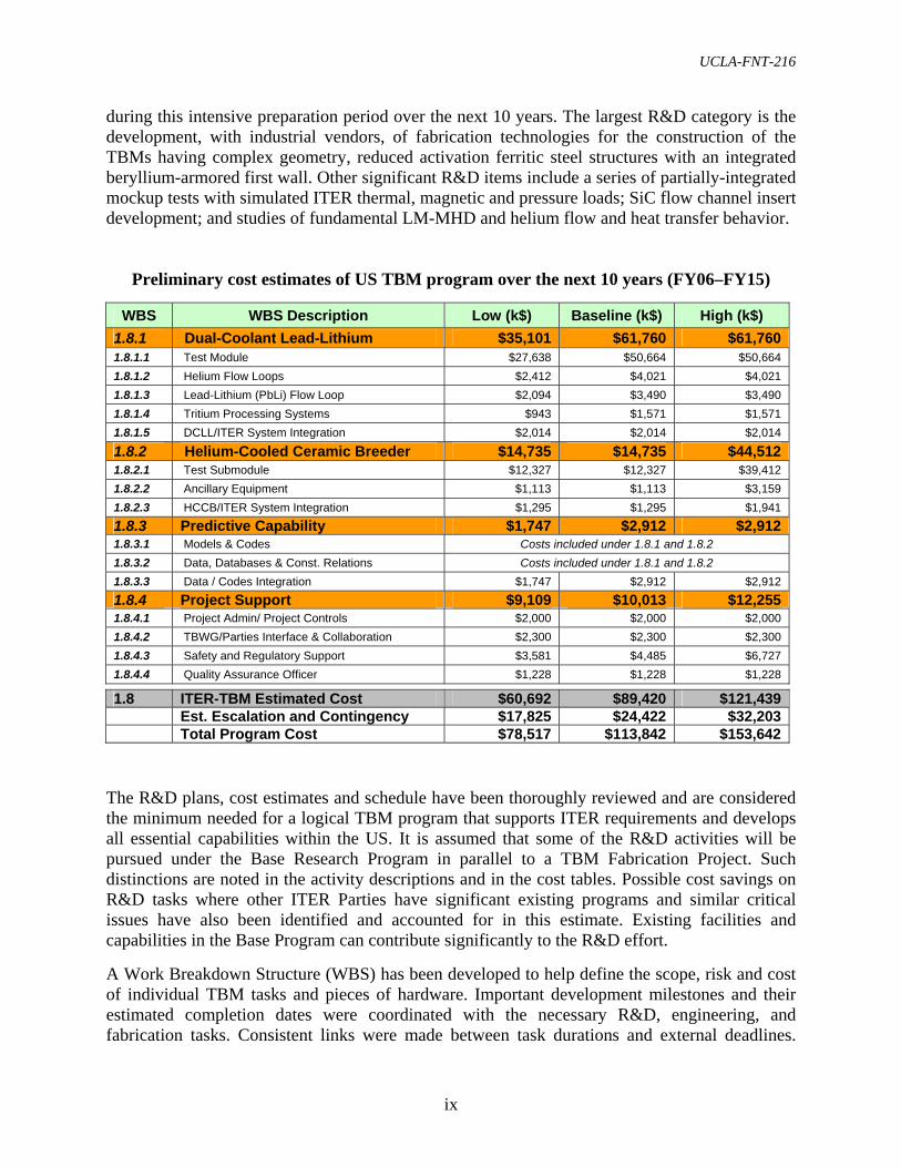
during this intensive preparation period over the next 10 years. The largest R&D category is the development, with industrial vendors, of fabrication technologies for the construction of the TBMs having complex geometry, reduced activation ferritic steel structures with an integrated beryllium-armored first wall. Other significant R&D items include a series of partially-integrated mockup tests with simulated ITER thermal, magnetic and pressure loads; SiC flow channel insert development; and studies of fundamental LM-MHD and helium flow and heat transfer behavior.
Preliminary cost estimates of US TBM program over the next 10 years (FY06–FY15)
WBS WBS Description Low (k$) Baseline (k$) High (k$) 1.8.1 Dual-Coolant Lead-Lithium $35,101 $61,760 $61,7601.8.1.1 Test Module $27,638 $50,664 $50,664 1.8.1.2 Helium Flow Loops $2,412 $4,021 $4,021 1.8.1.3 Lead-Lithium (PbLi) Flow Loop $2,094 $3,490 $3,490 1.8.1.4 Tritium Processing Systems $943 $1,571 $1,571 1.8.1.5 DCLL/ITER System Integration $2,014 $2,014 $2,014
1.8.2 Helium-Cooled Ceramic Breeder $14,735 $14,735 $44,5121.8.2.1 Test Submodule $12,327 $12,327 $39,412 1.8.2.2 Ancillary Equipment $1,113 $1,113 $3,159 1.8.2.3 HCCB/ITER System Integration $1,295 $1,295 $1,941 1.8.3 Predictive Capability $1,747 $2,912 $2,9121.8.3.1 Models & Codes Costs included under 1.8.1 and 1.8.2 1.8.3.2 Data, Databases & Const. Relations Costs included under 1.8.1 and 1.8.2 1.8.3.3 Data / Codes Integration $1,747 $2,912 $2,912 1.8.4 Project Support $9,109 $10,013 $12,2551.8.4.1 Project Admin/ Project Controls $2,000 $2,000 $2,000 1.8.4.2 TBWG/Parties Interface & Collaboration $2,300 $2,300 $2,300 1.8.4.3 Safety and Regulatory Support $3,581 $4,485 $6,727 1.8.4.4 Quality Assurance Officer $1,228 $1,228 $1,228
1.8 ITER-TBM Estimated Cost $60,692 $89,420 $121,439 Est. Escalation and Contingency $17,825 $24,422 $32,203 Total Program Cost $78,517 $113,842 $153,642
The R&D plans, cost estimates and schedule have been thoroughly reviewed and are considered the minimum needed for a logical TBM program that supports ITER requirements and develops all essential capabilities within the US. It is assumed that some of the R&D activities will be pursued under the Base Research Program in parallel to a TBM Fabrication Project. Such distinctions are noted in the activity descriptions and in the cost tables. Possible cost savings on R&D tasks where other ITER Parties have significant existing programs and similar critical issues have also been identified and accounted for in this estimate. Existing facilities and capabilities in the Base Program can contribute significantly to the R&D effort. A Work Breakdown Structure (WBS) has been developed to help define the scope, risk and cost of individual TBM tasks and pieces of hardware. Important development milestones and their estimated completion dates were coordinated with the necessary R&D, engineering, and fabrication tasks. Consistent links were made between task durations and external deadlines.

x
Costs were estimated and collected at all levels of the WBS. Subject matter experts were assigned to WBS elements and asked to evaluate labor efforts, material and equipment costs, and travel needed to complete the tasks as described in the respective technical plans. These cost estimates were presented, reviewed and modified as needed before being integrated into the schedule and total program cost. Project management and costing professionals participated in the effort and provided guidelines and review. The utilization of the ITER environment for fusion nuclear technology experiments and testing is essential for the US to build knowledge, experience, and competence in fusion nuclear and tritium technologies that are vital to the feasibility, practicality, and safety of D-T fusion devices. Only the Parties who will do successful effective TBM experiments in ITER will have the experimentally-validated scientific basis to embark on the engineering development of the tritium breeding blanket and its integrated plasma-facing first wall. The information presented in this document is intended to serve as the foundation for establishing a cost-effective and risk-tolerant, world-class US TBM program that will help demonstrate that ITER promotes progress toward fusion as a reliable and affordable energy source. -
UCLA-FNT-216
xi
TABLE OF CONTENTS
PREFACE..................................................................................................................................... iii
EXECUTIVE SUMMARY .......................................................................................................... v
LIST OF FIGURES ................................................................................................................... xiv
LIST OF TABLES ...................................................................................................................... xv
1. INTRODUCTION TO US TBM PROGRAM STRATEGY, DELIVERABLES, AND REQUIREMENTS.................................................................................................................... 1 1.1 BASELINE STRATEGY AND ALTERNATIVE SCENARIOS........................................ 2
1.2 SUMMARY OF BASELINE TBM DELIVERABLES....................................................... 3
1.3 SUMMARY OF ITER REQUIREMENTS AND DOE GUIDELINES .............................. 4
2. INTERNATIONAL ITER TEST BLANKET PROGRAM.................................................. 7 2.1 OVERALL ITER TEST BLANKET PROGRAM MISSION AND OBJECTIVES ........... 7
2.2 ITER TEST BLANKET WORKING GROUP (TBWG) ..................................................... 7
2.3 ITER PARAMETERS AND SCHEDULE........................................................................... 8
2.4 INTERNATIONAL PARTNER PROGRAMS.................................................................... 9
2.5 POTENTIAL IMPACT OF NECESSARY INTERNATIONAL COLLABORATION ... 11
3. US TBM STRATEGY, REFERENCE CONCEPTS AND DELIVERABLES................. 13 3.1 MISSION, OBJECTIVES AND SCIENTIFIC JUSTIFICATION .................................... 13
3.2 US SELECTED CONCEPTS AND STRATEGY ............................................................. 14 3.2.1 DUAL-COOLANT LEAD-LITHIUM (DCLL) BLANKET CONCEPT ................... 14 3.2.2 HELIUM COOLED CERAMIC BREEDER (HCCB) BLANKET CONCEPT......... 16
3.3 ASSUMPTIONS AND CONSTRAINTS AFFECTING US STRATEGY, TECHNICAL PLANNING, AND COST ESTIMATIONS....................................................................... 19
3.3.1 ITER DESIGN REQUIREMENTS, QUALITY ASSURANCE, AND ACCEPTANCE............................................................................................................................................... 20 3.3.2 TBM PLANNING GUIDELINES AGREED WITH DOE......................................... 24
3.4 SPECIFIC QUANTITATIVE GOALS AND DELIVERABLES...................................... 25
4. DESCRIPTION OF TBM DESIGNS AND PERFORMANCE PARAMETERS ............ 27 4.1 ITER INTERFACES AND TEST PORT DESCRIPTION................................................ 27
4.1.1 TBM SYSTEM ARRANGEMENT ............................................................................ 27 4.1.2 OTHER ITER INTERFACES ..................................................................................... 28
4.2 DCLL REFERENCE CONCEPTUAL DESIGN............................................................... 29 4.2.1 DCLL TBM DESIGN.................................................................................................. 30 4.2.2 DCLL TBM ANCILLARY CIRCUITS ...................................................................... 30
4.3 HCCB REFERENCE CONCEPTUAL DESIGN............................................................... 34

xii
4.3.1 HCCB SUB-MODULE TEST ARTICLE ................................................................... 34 4.3.2 HCCB ANCILLARY EQUIPMENT .......................................................................... 35
5. TBM TECHNICAL PLAN OVER THE NEXT 10 YEARS............................................... 39 5.1 DUAL-COOLANT LEAD-LITHIUM (DCLL) TECHNICAL PLAN SUMMARY ........ 40
5.1.1 DCLL R&D ................................................................................................................. 42 5.1.2 DCLL ENGINEERING DESIGN AND ANALYSIS................................................. 43 5.1.3 DCLL FABRICATION AND QUALIFICATION ..................................................... 48
5.2 HELIUM COOLED CERAMIC BREEDER (HCCB) TECHNICAL PLAN SUMMARY ........................................................................................................................ 48
5.2.1 HCCB RESEARCH AND ENGINEERING DEVELOPMENT ................................ 49 5.2.2 HCCB ENGINEERING DESIGN AND ANALYSIS ................................................ 50 5.2.3 HCCB FABRICATION AND QUALIFICATION ..................................................... 53
5.3 PREDICTIVE CAPABILITY TECHNICAL PLAN ......................................................... 53 5.3.1. MODELS AND CODES ............................................................................................ 53 5.3.2 DATA AND DATABASES ........................................................................................ 54 5.3.3 DATA/CODES INTEGRATION ................................................................................ 54
6. TBM PROGRAM COST ESTIMATES ............................................................................... 57 6.1 WORK BREAKDOWN STRUCTURE AND COLLABORATION MODELS............... 57
6.2 COST SCENARIO DEFINITIONS ................................................................................... 58 6.2.1 HIGH COST RANGE SCENARIO............................................................................. 58 6.2.2 BASELINE COST RANGE SCENARIO ................................................................... 59 6.2.3 LOW COST RANGE SCENARIO.............................................................................. 60
6.3 COST RANGE SUMMARY.............................................................................................. 60
6.4 US TBM BASELINE COST ESTIMATE SUMMARY.................................................... 61
6.5 ESTIMATED DIVISION BETWEEN TBM PROJECT AND BASE RESEARCH PROGRAM ......................................................................................................................... 61
6.6 ESTIMATED COSTS FOR STANDALONE DCLL AND HCCB DEVELOPMENT .... 67
7. INTEGRATED SCHEDULE................................................................................................. 69
8. ESCALATION AND CONTINGENCY............................................................................... 77
8.1 ESCALATION ................................................................................................................... 77
8.2 CONTINGENCY................................................................................................................ 77
9. RISK ASSESSMENT ............................................................................................................. 79 9.1 DCLL RISK HIGHLIGHTS............................................................................................... 79
9.2 HCCB RISK HIGHLIGHTS .............................................................................................. 80
10. FUNDING PROFILE ........................................................................................................... 83
APPENDIX A. GLOSSARY OF ACRONYMS AND ABBREVIATIONS........................... 85
APPENDIX B. DETAILED WORK BREAKDOWN STRUCTURE TABLES................... 87

UCLA-FNT-216
xiii
APPENDIX C. DOE REVIEW COMMITTEE RECOMMENDATIONS AND TBM COMMUNITY RESPONSE ................................................................................................. 93 REVIEW EXECUTIVE SUMMARY...................................................................................... 93
A.1 INTRODUCTION ............................................................................................................. 94
A.2 REVIEW CHARGE........................................................................................................... 94
A.3 FINDINGS & COMMENTS ............................................................................................. 97
A.4 RECOMMENDATIONS................................................................................................. 101

xiv
LIST OF FIGURES
Figure 2-1: ITER operational plan calling for TBM testing during entire H-H plasma phase......8
Figure 3-1: Idealized unit cell of the DCLL blanket concept, and radial variations in calculated temperature through a unit cell near the FW of a DCLL blanket in DEMO, showing the impact of FCI electrical conductivity owing to strong changes in PbLi velocity profile ...............................................................................15
Figure 3-2: The proposed US HCCB sub-module occupies 1/3 of an ITER horizontal half-port ....................................................................................................................18
Figure 4-1: Layout of a test port area including power extraction and tritium equipment in the AEU, and plan view of the ITER vacuum vessel and building showing locations of TBM test ports ..........................................................................................................27
Figure 4-2: Views of a vertically divided test blanket frame, isometric, and front view with dimensions ................................................................................................................28
Figure 4-3: Simplified block diagram of main DCLL systems and their location in ITER ........30
Figure 4-4: Views of DCLL TBM showing key features and current dimensions .....................33
Figure 4-5: DCLL TBM power handling and tritium system equipment in the AEU and in the TCWS vault ..............................................................................................................34
Figure 4-6: Stand-alone view of conceptual US HCCB sub-module ..........................................36
Figure 4-7: Calculated He velocity and temperature characteristics in FW and breeding zone cooling plates ............................................................................................................36
Figure 4-8: Exploded view of the HCCB sub-module ................................................................37
Figure 4-9: Port and port cell layout of ancillary conditioning equipment and measurement systems for the HCCB test sub-module....................................................................38
Figure 5-1: TBM program upper level Work Breakdown Structure ...........................................39
Figure 5-2: Logical and temporal layout of activities for DCLL TBM development .................41
Figure 5-3: HCCB schedule showing critical R&D feeding in to H-H phase TBM activities: design, material procurement, operating conditions definition, and international collaboration .............................................................................................................51
Figure 7-1: US TBM Integrated Program Schedule (IPS) – Major Tasks and Milestones ...71–75
Figure 10-1: US TBM baseline scenario funding profile by fiscal year through March 2015......83
UCLA-FNT-216
xv
LIST OF TABLES Table 2-1: ITER parameters for Test Blanket Module design .....................................................9
Table 2-2: Blanket concepts proposed by ITER Parties for ITER testing .................................10
Table 3-1: Potential US DCLL TBM sequence and ITER testing goals during the first 10 years of ITER operation.......................................................................................17
Table 3-2: Summary of top level qualification requirements and proposed US actions............22
Table 4-1: DCLL TBM reference design parameters for D-T operation ...................................31
Table 4-2: Preliminary DCLL ancillary loops design parameters..............................................32
Table 4-3: Rough dimensions and weights of the primary helium cooling loop components ...32
Table 5-1: DCLL R&D areas and their top level purpose and description ..........................44–46
Table 5-2: HCCB R&D areas and their top level purpose and description...............................52
Table 6-1: US ITER TBM cost range breakdown by major WBS elements..............................62
Table 6-2: US ITER TBM total program cost range breakdown by major WBS elements including escalation and contingency .......................................................................63
Table 6-3: US ITER TBM baseline scenario cost estimates showing contingency on each major WBS element..................................................................................................64
Table 6-4: Possible division of costs between a TBM Project and Base Research Program including escalation and contingency .......................................................................65
Table 6-5: Summary of TBM program baseline scenario R&D costs, savings attributed to known international collaborations, and possible division into TBM Project and Base Program............................................................................................................66
Table 9-1: Summary of main risks, consequences, and mitigating actions .........................81–82
Table B-1: Detailed DCLL System (1.8.1) Work Breakdown Structure .............................87–89
Table B-2: Detailed HCCB System (1.8.2) Work Breakdown Structure...................................90
Table B-3: Detailed Predictive Capability (1.8.3) Work Breakdown Structure.........................91
Table B-4: Detailed Project Support (1.8.4) Work Breakdown Structure .................................91

xvi
This page intentionally left blank

UCLA-FNT-216
1
1. INTRODUCTION TO US TBM PROGRAM STRATEGY, DELIVERABLES, AND REQUIREMENTS Testing tritium breeding blanket modules is one of the principal objectives of ITER. Blankets are essential, complex components that integrate a plasma-facing first wall, breeding material, neutron multiplier material, high temperature coolant, reduced activation structure, and special materials such as tritium permeation barriers and insulators. Blanket components must operate safely and reliably in a harsh environment. No fusion blanket has ever been built or tested, and their integrated function, reliability, and lifetime are by no means assured. ITER presents the first opportunity to test blanket materials and components in an actual fusion environment after many years of research, development and design in the domestic programs. ITER test blanket module (TBM) testing represents a critical step toward establishing the principles and technologies of tritium self-sufficiency and energy extraction – on which the feasibility of deuterium-tritium fusion energy production relies. The ITER International Team (IT), now the International Organization (IO), has allocated three equatorial ports for blanket module testing, and has constituted the ITER Test Blanket Working Group (TBWG) to integrate into ITER the testing programs of the Parties. The ITER TBWG is officially charged with:
a) developing a coordinated Test Blanket Module (TBM) program in ITER, taking into account the ITER operational plan,
b) promoting and facilitating cooperation among the ITER Parties, particularly on the R&D for TBMs, and
c) defining the details of the engineering interfaces with the basic device and integrating TBM testing into ITER site safety and environmental evaluations.
The US community has been engaged during the past several years in identifying blanket concepts for testing in ITER, developing conceptual designs and testing strategy for TBMs, evaluating key technical issues, and identifying the required research and development tasks (R&D). The US has been an active member of the TBWG and has made strong contributions, particularly in regard to defining the detailed interfaces to the main ITER machine, enhancing coordination and cooperation among the Parties, and ensuring that the US has rights to testing space and access to ITER facilities that are equivalent to those of the other Parties. The TBWG has made considerable progress toward developing a framework for the test program to define ITER interfaces and provide information on TBMs and their ancillary systems for safety evaluation and licensing. A formal agreement among the Parties on sharing the limited testing space and time, as well as sharing data from the test program and handling intellectual property rights, is currently under discussion, but has not yet been reached. This report provides technical information, execution plans, and cost estimates for a range of options to aid DOE in selecting a specific strategy for US participation in the ITER TBM Program. This activity was requested by the US Department of Energy (DOE). The technical plan and the costing information were developed by the US ITER TBM team (which includes

2
scientists and engineers from the Plasma Chamber, Materials, Safety, Tritium, and Plasma-Facing Components program elements of the DOE Office of Fusion Energy Sciences), complemented by input from project costing and scheduling professionals. Interactions with the ITER IT/IO and TBM experts from the other Parties have also provided important input to this activity. This planning and costing effort has followed the methodologies developed by the US ITER Project Office to the maximum extent possible (for example, in developing a Work Breakdown Structure (WBS) and in evaluating costs). The report itself is organized so as to present important background material regarding ITER testing and the international test program, followed by detailed information concerning the proposed US concepts, strategies, costs, schedules, and risks. Chapter 2 summarizes the key aspects of the international ITER Test Program. It defines the ITER schedule, describes the physical and operating environment for the TBMs, and summarizes important TBWG conclusions and other Parties’ TBM programs. This information illustrates the programmatic and technical constraints under which the US TBM program must operate. Chapters 3–5 provide technical information on the US TBMs. Chapter 3 describes the US TBM concepts and testing strategy, as well as the program’s mission, objectives, and deliverables. Assumptions and constraints are also summarized. Chapter 4 describes the US TBM designs and their performance parameters. Chapter 5 describes the US TBM technical plan, including R&D, engineering design and analysis, mockup and prototype tests, and fabrication and qualification. Chapter 6 presents a detailed summary of the possible cost ranges for the TBM program, based on different scenarios for international collaboration. Chapter 7 shows the integrated program schedule and a list of key milestones and their estimated completion dates. Chapter 8 evaluates cost escalation and contingency. Considerations of risk are addressed in Chapter 9. The funding profile is given in Chapter 10. A considerable amount of detailed supporting information was generated in developing this report. Much of this detail is provided in the companion volume to this report [1-1]. For convenience, a summary of program strategy, deliverables, and requirements is provided below, and tables defining common acronyms, lists of detailed schedule tasks, and the report from the DOE-charged review committee are provided in the appendices. 1.1 BASELINE STRATEGY AND ALTERNATIVE SCENARIOS A recommended baseline US strategy for ITER TBMs has been developed and serves as the basis for the technical information in this report. Two blanket concepts, the Dual-Coolant Lead-Lithium (DCLL) and the Helium-Cooled Ceramic Breeder (HCCB), have been selected by the US for ITER testing. A series of consecutive TBMs is planned for the first 10 years of ITER operation, each with a different technical mission and unique set of diagnostics designed to maximally exploit the ITER testing environment available during their respective plasma operational phase. For the DCLL, an independent TBM is proposed that will occupy half of an ITER test port (1660 (H) × 484 (W) mm), with supporting ancillary equipment including helium
UCLA-FNT-216
3
and PbLi coolant loops, tritium processing systems, and diagnostic and control systems. DCLL tests in ITER during the first 10 years will operate with PbLi outlet temperature at or below the compatibility limit with RAFS (~470ºC), so that high temperature external loop systems are not initially required, but the key features of the DCLL blanket itself can still be tested and studied. The US baseline strategy for the HCCB concept is to test a series of sub-modules that have a size of 1/3 of one-half port, each with its own first wall structure (710 (H) × 389 (W) mm), and sharing cost and space for ancillary equipment with international partners. The worldwide TBM programs have historically been highly collaborative and, in developing this US plan, it was recognized that the level of assumed international collaboration is a larger driver of overall program costs than uncertainty in other areas. To address this reality, cost estimates are developed (Chapter 6) for two scenarios in addition to the baseline scenario, forming the high and low cost ranges. The primary distinction between the baseline, high, and low cost range scenarios is the degree of international collaboration and cost sharing with other parties:
• The high cost range scenario is for an independent US DCLL TBM and an independent HCCB TBM. This is similar to EU, Japan, and most other parties in independently testing two full modules.
• The baseline scenario consists of an independent US DCLL TBM, and a supporting partnership with other Party(ies) (Japan, EU, KO) on the HCCB TBM, providing only a 1/3 size sub-module.
• The low cost range scenario is defined as a leading international partnership (with one or more ITER Parties) on the DCLL TBM and a supporting partnership on the HCCB TBM.
These alternative cost scenarios are addressed only in Chapter 6. 1.2 SUMMARY OF BASELINE TBM DELIVERABLES A summary of the key deliverables is given below for convenience. The deliverables are discussed in detail in later chapters. (Note that, as indicated above, all information is for the baseline scenario unless stated otherwise. In ITER and TBWG terminology, a “full size” TBM occupies one-half of an ITER Test Port. A “1/3 size” TBM occupies one-third of one-half of an ITER Test Port.) Deliverables
1. A qualified, full size, DCLL TBM for operation in the ITER H-H phase 2. Associated DCLL ancillary systems needed for DCLL operation in the H-H phase,
including helium and PbLi coolant loops, and diagnostics and control systems 3. A qualified, 1/3 size, HCCB TBM for operation in the ITER H-H phase 4. A one-third portion of the HCCB ancillary systems needed for HCCB operation in the
H-H phase, including helium coolant and purge gas loops, and diagnostic and control systems

4
5. Component specifications sufficient to fabricate the tritium processing systems 6. A verified predictive capability sufficient to design, qualify, operate, and interpret data
for the H-H phase TBMs, and to design later D-D and D-T phase TBMs and ancillary systems and diagnostic systems
1.3 SUMMARY OF ITER REQUIREMENTS AND DOE GUIDELINES The requirements affecting the R&D, design and fabrication of the deliverables, and the planning and scope of the TBM program described in this report come from both ITER and the US DOE. Some key points are given here for emphasis, with a more detailed summary given in Section 3.3 and in Refs. [1-2]. Some requirements have yet to be fully quantified and will be evolved in the near future. Primary ITER Requirements
• TBMs must:
o be DEMO relevant o not interfere with ITER operation, decrease reliability, or compromise safety o be tested in the H-H phase
• TBMs must operate successfully with:
o a plasma pulse length of 400 s o a surface heat flux with peaks of 0.3 MW/m2 during the ITER H-H phase pulses
and 0.5 MW/m2 during the D-T phase pulses o a neutron wall load with peaks of 0.78 MW/m2 during the ITER D-T phase pulses o the ITER electromagnetic environment
• Qualified TBMs and systems for H-H plasma phase operation should be completed 18
months prior to first plasma Baseline Planning Guidelines The following set of guidelines for planning the US TBM program was agreed to among the US TBM team and with the DOE.
• The DCLL reference scenario assumes the testing of a series of TBMs, each of which will occupy an ITER vertical half-port, have dedicated ancillary equipment, and have a PbLi exit temperature limit of 470ºC.
• The HCCB reference scenario assumes a series of sub-modules, each of which will occupy 1/3 of an ITER horizontal half-port and utilize shared ancillary equipment in-cooperation with the EU, Japan, or another Party.
• US TBM structures will be fabricated from reduced activation ferritic steel with an assumed operating temperature limit of 550ºC.

UCLA-FNT-216
5
• Detailed planning and cost estimation is for the roughly 10-year period including FY06 through the completion of deliverables by the end of March 2015, intended for ITER H-H operation.
• The cost estimate should include the total cost for the TBM deliverables including R&D, design, engineering, fabrication, qualification, etc., as well as the cost to coordinate with ITER and other Parties during this period.
• The R&D cost includes all costs related to the Reference Scenarios that occur within the performance period, whether they are related to the first (ITER H-H phase) test articles or subsequent test articles.
• The cost estimate is for a complete TBM preparatory program. The estimate is further broken down into tasks that likely fall under the “Base Research Program” and a “TBM Fabrication Project” as requested by DOE in response to the interim review.
REFERENCES: [1-1] “US ITER Test Blanket Modules (TBM) Program. Volume II: Technical Plan and Cost
Estimate Supporting Information,” UCLA-FNT-217 (April 2007). [1-2] “Report from the re-established Test Blanket Working Group (TBWG) for the Period of
the ITER Transitional Arrangements (ITA)” (September 2005).

6
This page intentionally left blank

UCLA-FNT-216
7
2. INTERNATIONAL ITER TEST BLANKET PROGRAM 2.1 OVERALL ITER TEST BLANKET PROGRAM MISSION AND OBJECTIVES Breeding blanket development is one of the most challenging issues for the design and construction of a fusion demonstration power reactor (DEMO). TBM tests in ITER will provide essential information toward resolving this challenge. For this reason, the testing of integrated blanket modules in special ports has been a principal objective of ITER since its inception over 20 years ago:
The ITER should serve as a test facility for neutronics, blanket modules, tritium production and advanced plasma technologies. The important objectives will be the extraction of high-grade heat from reactor relevant blanket modules appropriate for generation of electricity. [2-1] ITER should test design concepts of tritium breeding blankets relevant to a reactor. The tests foreseen in modules include the demonstration of a breeding capability that would lead to tritium self sufficiency in a reactor, the extraction of high-grade heat and electricity generation. [2-2]
The major testing objectives are: 1) validation of theoretical predictions of structural integrity and response under combined relevant thermal, mechanical and electromagnetic loads; 2) validation of tritium breeding predictions; 3) validation of tritium recovery process efficiency and tritium inventories in blanket materials; 4) validation of thermal predictions for heterogeneous breeding blanket concepts with spatially dependent volumetric heat sources; 5) demonstration and understanding of the integral performance of the blanket systems. Many ITER Parties view blanket module testing in ITER as their only component-level testing step before a DEMO reactor. 2.2 ITER TEST BLANKET WORKING GROUP (TBWG) More than a decade ago, in the early stages of the ITER project, the ITER Parties decided to keep the management of the TBM program independent of that for ITER design and construction because TBM was, and still is, considered to be key to each Party’s competitiveness in the construction of devices beyond ITER, e.g., DEMO. In order to help realise the TBM testing mission, the ITER Test Blanket Working Group (TBWG) was officially established by the ITER Council and charged to define, coordinate, and integrate an appropriate breeding blanket testing program in ITER. The TBWG is composed of representatives from the ITER IO and representatives from each of the ITER Parties. The TBWG is chartered to: 1) provide the Design Description Document (DDD) for each TBM system proposed by the Parties, including the description of their interfaces with the main ITER machine; 2) promote cooperation among the Parties on the associated R&D programs; 3) verify the integration of TBM testing in the ITER site safety and environmental evaluations; and finally, 4) develop a coordinated TBM test program, taking into account ITER operation planning and the Parties’ test program goals.

8
The TBWG made a preliminary assessment of the testing capabilities of the present ITER machine in July 2001 at the end of the ITER EDA extension phase, and defined the framework of a coordinated testing program, including the set of Test Blanket Modules to be tested during the different phases of ITER operation [2-3, 2-4]. The TBWG has continued its activity since October 2003 with an enlarged official membership, including all the new ITER Parties. In September 2005, a revised assessment report [2-5] was submitted to the ITER Preparatory Committee. TBWG will continue in its present format with an additional focus on safety and on the evaluation of needed resources for ITER interfaces. 2.3 ITER PARAMETERS AND SCHEDULE The overall ITER operational plan through the first ~10 years is summarized in Fig. 2-1. It is preceded by one year of integrated commissioning of in-vessel components. The 10-year plan includes 2.5 years of initial H-H operation; a brief D-D phase; and an approximately six-year-long D-T phase. The operational parameters of these phases are summarized in Table 2-1. During the D-T phase, typical operating conditions for the TBMs include an average first wall surface heat flux of 0.27 MW/m2 (during a plasma pulse), a neutron wall load of 0.78 MW/m2 (during a plasma pulse), and a pulse length of 400 s (or longer) with a duty cycle of 22% (or higher). These parameters are used in the conceptual designs of US TBMs discussed in the following chapters.
Figure 2-1: ITER operational plan calling for TBM testing during entire H-H plasma phase

UCLA-FNT-216
9
To ensure that the test blanket modules and their systems are compatible with the tokamak operation and are fully tested and integrated prior to initiation of the D-D and D-T ITER phases, the TBWG and ITER IO have mandated that test modules or their representative equivalents must be installed and tested before and during the hydrogen plasma operation. There are several issues which must be investigated during this period:
• test module and systems integration into the ITER port and systems; • interference of the test modules with plasma confinement, including the effects of
ferritic/martensitic steels on the ITER magnetic confinement fields; • operation of the test modules, diagnostics, and supplementary equipment in a strong
magnetic field; • test module structural loads and corresponding responses owing to surface heat flux on
the test module first wall during normal plasma discharges, and including spatially non-uniform heat fluxes, for instance, from plasma MARFEsa;
• test module structural loads and corresponding responses during tokamak startup and shutdown, including transient events like plasma disruptions; and
• material erosion and transport from the test module first wall and the necessity of using a beryllium protective layer (the current requirement is for a 2 mm Be layer).
Table 2-1: ITER parameters for Test Blanket Module design
Loading Parameters H-H phase
Design (Typical) Values
D-T phase Design (Typical)
Values Peak heat flux (MW/m2) 0.11 for 600 cycles/yr,
1000 cycles for 2.5 yr 0.27-0.38 for 3000 cycles/yr
Maximum FW surface heat flux (MW/m2) 0.3 localized from MARFE 0.5 localized for 100 cycles/yr
Neutron wall load (MW/m2) - 0.78 (0.78)
Pulse length (sec) Up to 400 400 up to 3000
Duty cycle (%) 0.22 > 0.22
Average FW neutron fluence (MWa/m2) - 0.1 (first 10 yrs) up to 0.3
2.4 INTERNATIONAL PARTNER PROGRAMS All ITER Parties have identified their favored DEMO-relevant blanket concepts for testing in ITER (see Table 2-2). All Parties are interested in developing a Helium-Cooled Ceramic Breeder (HCCB) blanket system. Some Parties propose to test independent TBMs based on their different domestic blanket concepts (China, EU, Japan and RF), and other Parties propose to collaborate on a common HCCB TBM to address generic issues (US, India, Korea). Depending on the
a “Multifaceted Asymmetric Radiation From the Edge” – poloidally asymmetric radiation bands due to plasma thermal instabilities

10
Parties’ domestic experience, the preferred ceramic breeder material is either Li2TiO3, Li4SiO4, or Li2O in pebble-bed form. The other proposed breeding blankets differ from Party to Party. Japan has selected a pressurized Water-Cooled Ceramic Breeder (WCCB) blanket, which is a water-cooled version of the corresponding HCCB blanket. All other Parties consider a liquid metal breeder option. The EU has selected a Helium-Cooled Lead-Lithium (HCLL) blanket, using lead-lithium (PbLi) as breeder and neutron multiplier. The US has selected a Dual-Coolant Lead-Lithium (DCLL) blanket system that uses helium to cool the structures, but has a self-cooled PbLi breeder zone. China is pursuing both the HCLL and the DCLL blankets. South Korea has proposed a Helium-Cooled Molten Lithium (HCML) blanket. India has proposed lead-lithium / ceramic breeder hybrid. All of the aforementioned blanket options utilize reduced activation ferritic steel as the structural material. Finally, the RF has selected a self-cooled Lithium blanket using vanadium-alloy structural material (Li/V). More detail on the ITER Parties’ proposed TBM programs is available in Refs. [2-5] and in numerous TBWG presentations by the Parties.
Table 2-2: Blanket concepts proposed by ITER Parties for ITER testing
Blanket Concept Acronym Materials Proposing Party
Helium-Cooled Ceramic Breeder HCCB
• RAFS Structure • Be multiplier • Ceramic breeder (Li2TiO3, Li4SiO4, Li2O) • Helium coolant and purge
EU, JA, RF, CN, US, KO, IN
Water-Cooled Ceramic Breeder WCCB
• RAFS structure • Be multiplier • Ceramic breeder (Li2O) • Water coolant, He purge
JA
Helium-Cooled Lead-Lithium HCLL
• RAFS structure • Molten Pb-17Li breeder/multiplier • Helium coolant
EU, CN
Dual-Coolant Lead-Lithium DCLL
• RAFS structure • SiC flow channel inserts • Molten Pb-17Li breeder/coolant • Helium coolant
US, CN
Helium-Cooled Molten Lithium HCML
• RAFS structure • Lithium breeder • Helium coolant
KO
Self-Cooled Lithium Li/V
• Vanadium alloy structure • Insulator barrier (e.g., AlN) • Lithium breeder/coolant
RF
Lead-Lithium Ceramic Breeder LLCB
• RAFS structure • Dual coolant Lead Lithium and Helium • Dual breeder Lead Lithium and Ceramic
IN

UCLA-FNT-216
11
2.5 POTENTIAL IMPACT OF NECESSARY INTERNATIONAL COLLABORATION It is clear that the Parties’ various TBMs cannot all be tested simultaneously. Space limitations exist, not only with respect to the space available in the test ports, but also to the limited space available in the port cells outside the bioshield behind each TBM, in the vertical shafts, and in the Tokamak Cooling Water System (TCWS) vault (discussed in more detail in Chapter 4). The TBWG has asked the ITER International Organization (IO) to review the TBM program needs and assign resources to formulate a plan to resolve them. This process is underway. In addition, all proposed TBMs need further R&D and rigorous qualification before their acceptance for installation and testing in ITER. It is likely that some proposals will be abandoned either for technical or financial reasons, and, therefore, it is important to allow some flexibility on the final choice of TBM concepts to be installed in each port. For this reason, the TBWG has requested [2-5] that each Party prepare a Design Description Document (DDD) for each TBM system proposed for testing in ITER, independent of any port allocation or space availability in ports, in the port cells, and in the TCWS vault.
As part of the TBWG mission, options for international collaboration on TBMs among the Parties are being deliberated. Examples of options being evaluated include scenarios where several Parties:
a) jointly develop, construct, and test a single blanket concept, and/or b) share responsibilities for R&D on similar blanket concepts, and/or c) fabricate and share ancillary equipment systems (e.g. helium loops).
Clearly, international collaboration could substantially reduce the cost to the US when compared to a fully independent TBM Program. The US TBM community will continue to negotiate toward the elimination of any unnecessary overlap in the TBM R&D and qualification programs, in an effort to optimize the overall effort and control costs. Early agreements on collaboration and cost sharing will help minimize risk and adverse impact on schedule.
REFERENCES [2-1] “The ITER Quadripartite Initiative Committee (QIC),” IEA Vienna (18–19 October,
1987). [2-2] SWG1, reaffirmed by ITER Council, IC-7 Records (14–15 December, 1994), and stated
again in forming the Test Blanket Working Group (TBWG). [2-3] “ITER Test Blanket Working Group, Report from the TBWG for the Period of Extension
of the EDA” (May 2001). [2-4] V.A. Chuyanov and the ITER Test Blanket Working Group, “ITER Test Blanket Working
Group Activities: a summary, recommendations and conclusions,” Fusion Engineering and Design, v. 61-62, p. 273 (2002).
[2-5] “Report from the re-established Test Blanket Working Group (TBWG) for the Period of the ITER Transitional Arrangements (ITA)” (September 2005).

12
This page intentionally left blank

UCLA-FNT-216
13
3. US TBM STRATEGY, REFERENCE CONCEPTS AND DELIVERABLES 3.1 MISSION, OBJECTIVES AND SCIENTIFIC JUSTIFICATION The development of “new materials, components, and technologies necessary to make fusion energy a reality” is a US Fusion Program need identified in the DOE Office of Fusion Energy Sciences Strategic Plan [3-1]. A key element in the strategic timeline to meet this program need is the “testing in ITER of blanket technologies needed in power producing fusion plants capable of extracting high-temperature heat from burning plasmas and having a self-sufficient fuel cycle.” A true fusion environment is essential to activate mechanisms that cause prototypical coupled phenomena, integrated behavior, and synergistic effects that can not be anticipated from simulations or studied in separate effects tests in the laboratory. The unique conditions of ITER that allow for meaningful integrated, multi-field, multi-physics testing of blanket components and material systems include:
• large test ports (maximum height of TBM ~ 2 m, similar to the size of typical blanket modules in a future power plant);
• plasma exposure with typical plasma radiation, particle loads, and startup/termination; • nuclear volumetric heating and beginning of life radiation damage with spatial gradients; • off-normal plasma events such as disruptions, ELMsb, VDEsc, etc.; • strong and spatially complex magnetic field (~ 5 T) of the same order as in power plants; • true fusion neutron energy spectrum as in power plantsd; and • strong confinement of radioactivity, allowing realistic tritium concentrations.
The utilization of ITER for fusion nuclear technology experiments and testing is essential for the US to build knowledge, experience, and competence in fusion nuclear and tritium technologies that are vital to the feasibility, practicality, and safety of D-T fusion devices. There are no current plans to build a more suitable test facility. ITER appears to be the only facility available to test blanket components for future D-T devices and experiments that must breed their own tritium. It is also clear that this testing leverages the significant US and international investment in ITER and in the various Parties’ domestic fusion technology programs – providing a significant scientific return to the US program from these investments. The principal mission of the US ITER Test Blanket Module (TBM) Program is to develop, deploy and operate ITER TBM experiments that provide unique experimental data on, and operational experience with, the integrated function of US blanket components and materials in a true fusion plasma-magnetic-nuclear-thermal-chemical environment. This data is essential for:
1. validation of the scientific understanding and predictive capabilities needed to interpret and extrapolate results to blanket performance in subsequent burning plasma experiments, component test facilities, and ultimately energy producing systems;
b “Edge Localized Modes” – instability resulting in significant particle and energy transfer from plasma pedestal region into the scrape-of-layer towards plasma facing components c “Vertical Displacement Events” – instability leading to rapid vertical movement of the plasma d but lower neutron wall load (~ 30 % of DEMO plant) and a fluence a few percent of typical DEMO end-of-life.

14
2. demonstration of the principles of tritium self-sufficiency in practical systems needed to establish the feasibility of the D-T fuel cycle (including limitations on options for improving plasma performance, e.g., conducting shells, embedded passive coils, thick armors/first wall);
3. development of the technology necessary to install breeding capabilities to supply ITER with the necessary tritium for its extended phase of operation and help resolve the critical “tritium supply” issue for fusion development (US involvement in the development of this technology with ITER partners will be essential to understand and influence these partner programs);
4. attainment of the first integrated experimental results on the reliability, safety, environmental impact, and efficiency of fusion energy extraction systems.
3.2 US SELECTED CONCEPTS AND STRATEGY The US plan for TBM experiments in ITER evolved through technical studies, reviews of current R&D status, considerations of technical trade-offs, and interactions with the community and the DOE, as well as interactions with the international ITER partners and with the TBWG. Two concepts, the Dual-Coolant Lead-Lithium and the Helium-Cooled Ceramic Breeder (introduced below and described in more detail in Chapter 4), have been selected. The two-concept strategy is strongly endorsed here in order to:
Keep the US involved in the development of two different classes of blanket concepts that have substantially different feasibility issues to avoid the situation where a fatal flaw eliminates one concept, either during the development phase over the next 10 years prior to ITER testing, or during the initial testing phase over the first 10 years of ITER operation; and
Capitalize on the significant international interest in these particular systems and so maximally leverage existing and near-term international R&D efforts and partnership opportunities.
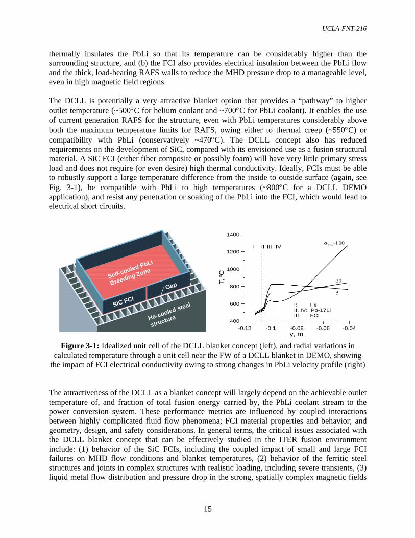
It should be noted that each of the ITER Parties also plans on testing two classes of blanket concepts (see Chapter 2 for more details concerning other ITER Parties’ programs). The general U.S. strategy for ITER testing is to progress from basic structural, thermal-hydraulic and magnetohydrodynamic (MHD) performance to more integrated testing goals in concert with the first 10 years of ITER operation. 3.2.1 DUAL-COOLANT LEAD-LITHIUM (DCLL) BLANKET CONCEPT The basic idea of the DCLL blanket is to use helium to remove all heat deposited in the blanket structure (including the surface heat flux on the first wall), and a flowing, self-cooled, PbLi alloy breeder to remove nuclear heat generated in the breeding zone – at a high temperature for efficient power conversion. The US DCLL concept consists of PbLi channels contained within a helium-cooled structure made of reduced activation ferritic steel (RAFS), as shown in Fig. 3-1. Each PbLi channel is lined with a SiC flow channel insert (FCI) that separates the main portion of the PbLi from the RAFS structure. This FCI performs two important functions: (a) the FCI
UCLA-FNT-216
15
thermally insulates the PbLi so that its temperature can be considerably higher than the surrounding structure, and (b) the FCI also provides electrical insulation between the PbLi flow and the thick, load-bearing RAFS walls to reduce the MHD pressure drop to a manageable level, even in high magnetic field regions. The DCLL is potentially a very attractive blanket option that provides a “pathway” to higher outlet temperature (~500°C for helium coolant and ~700°C for PbLi coolant). It enables the use of current generation RAFS for the structure, even with PbLi temperatures considerably above both the maximum temperature limits for RAFS, owing either to thermal creep (~550°C) or compatibility with PbLi (conservatively ~470°C). The DCLL concept also has reduced requirements on the development of SiC, compared with its envisioned use as a fusion structural material. A SiC FCI (either fiber composite or possibly foam) will have very little primary stress load and does not require (or even desire) high thermal conductivity. Ideally, FCIs must be able to robustly support a large temperature difference from the inside to outside surface (again, see Fig. 3-1), be compatible with PbLi to high temperatures (~800°C for a DCLL DEMO application), and resist any penetration or soaking of the PbLi into the FCI, which would lead to electrical short circuits.
Self-cooled PbLi
Breeding Zone
He-cooled steel
structure
SiC FCI
Gap
Figure 3-1: Idealized unit cell of the DCLL blanket concept (left), and radial variations in calculated temperature through a unit cell near the FW of a DCLL blanket in DEMO, showing
the impact of FCI electrical conductivity owing to strong changes in PbLi velocity profile (right) The attractiveness of the DCLL as a blanket concept will largely depend on the achievable outlet temperature of, and fraction of total fusion energy carried by, the PbLi coolant stream to the power conversion system. These performance metrics are influenced by coupled interactions between highly complicated fluid flow phenomena; FCI material properties and behavior; and geometry, design, and safety considerations. In general terms, the critical issues associated with the DCLL blanket concept that can be effectively studied in the ITER fusion environment include: (1) behavior of the SiC FCIs, including the coupled impact of small and large FCI failures on MHD flow conditions and blanket temperatures, (2) behavior of the ferritic steel structures and joints in complex structures with realistic loading, including severe transients, (3) liquid metal flow distribution and pressure drop in the strong, spatially complex magnetic fields
-0.12 -0.1 -0.08 -0.06 -0.04y, m
400
600
800
1000
1200
1400
T, o C
I II III IV
5
20
σSiC=100
I: FeII, IV: Pb-17LiIII: FCI

16
of the tokamak, (4) helium flow thermal-hydraulics in highly non-isothermal and complex blanket channels, (5) tritium breeding, control and extraction in a multi-material, highly heterogeneous, coupled system, and (6) integrated effects on blanket operation, including early effects of radiation damage. The US plan proposes an independent US DCLL TBM that will occupy half an ITER test port, along with corresponding ancillary equipment, including coolant loops and tritium processing systems. All systems will operate within the material limits of current generation ferritic steel. The PbLi exit temperature is limited to 470°C in order to avoid the need for immediate development of higher temperature external piping. Even at these temperatures, the DCLL is a reactor relevant blanket system, and features of higher-temperature operation can be effectively studied. A series of consecutive TBMs is currently planned for the first 10 years of ITER operation, each with a different technical mission and unique set of diagnostics designed to maximally utilize the ITER integrated fusion environment, while minimizing the technical development required (see Table 3-1 for a more detailed description of a possible testing sequence). Studies of basic feasibility and operational issues are planned, as well as of phenomena and operational scenarios relevant to higher temperature DCLL operation by using extrapolation and scaling, and the control of primary/secondary helium and PbLi temperatures via their respective flowrates and inlet temperatures. Maximum flexibility will be incorporated into the design of the TBMs and system, to allow exploration of the largest set of parameters and conditions of interest for fusion. It should be noted that a final decision on the number of TBMs must be evaluated in the future based on such factors as (1) the detailed optimized technical mission and design of each experiment, (2) any possibility to perform similar tests in collaboration with other parties, (3) availability of needed diagnostics with sufficient accuracy, (4) decisions on testing space and time allocations, etc. However, it is clear that some manner of “break-in” testing will be needed during the H-H phase to study TBM effects on plasma operation and perform ITER correction coil adjustment; and determine TBM operational and control procedures prior to the D-D and D-T nuclear operations. Since the cost estimate and schedule provided in this report is for the development and fabrication of the first TBM to be installed in ITER in the next 10 years, this cost and schedule is affected only slightly by a change in the total number of TBMs to be tested in ITER. 3.2.2 HELIUM COOLED CERAMIC BREEDER (HCCB) BLANKET CONCEPT The helium-cooled ceramic breeder blanket (HCCB) concept, utilizing reduced activation ferritic steel as structural material, is a leading blanket option for fusion energy reactor applications under moderate neutron wall loads (~2.5 MW/m2). The ceramic breeder blanket concept is also the most likely candidate for near-term tritium breeding blankets, for instance, in an extended performance phase of ITER. The HCCB concept uses an immobile lithium ceramic breeder in the form of a pebble bed for tritium production, from which the tritium is removed by diffusion into a low pressure helium purge gas flow. Typically, the breeder beds are interspersed with beryllium pebble beds for neutron multiplication, with the different beds separated by cooled

UCLA-FNT-216
17
Table 3-1: Potential US DCLL TBM sequence and ITER testing goals during the first 10 years of ITER operation (~FY17 – FY27)
Name Experimental Goals ITER
Phase & Duration
1st -TBM EM / Structural
• Establish testing capability, system performance baseline, and operation experience prior to D-T (nuclear) operation, including diagnostic and control system operation, heat transfer and thermal time constant determination
• Validate DCLL TBM structure and FCI response to EM/Plasma during normal operation and transient events prior to D-T phase
• Perform initial studies of MHD effects in ITER fields, particularly flow distribution and pressure drop
H-H for
3 years
2nd-TBM
Nuclear Field/ Tritium Production
• Establish neutron field measurements database for various types of ITER discharges and conditions
• Measure tritium production rate (TPR), and nuclear heating rates • Validate FW He cooling at full load and determine FW tritium
implantation effects • Establish tritium processing capability prior to D-T operation
D-D + Early D-T
for 2 years
3rd-TBM Thermofluid / MHD
• Quantify the thermal and electrical insulation properties of the FCI and FCI failure modes and effects
• Study tritium transport and control through FCIs, RAFS, and PbLi and He coolant streams
• Establish the PbLi flow behavior with nuclear heating and natural convection
• Establish initial behavior of activation product generation, transport, and chemistry control in the PbLi coolant
Low duty D-T for 2 years
4th-TBM Integrated
• Investigate various scenarios for TBM operation, including synergistic effects of flow and FCI behavior, tritium permeation, and corrosion and activation product generation and transport
• Investigate online tritium recovery and control from PbLi and He streams
• Investigate online PbLi and He coolant purification systems • Explore longer-term integrated operation of the system, including
small accumulation of radiation damage in FCIs and RAFS joints
High duty D-T for
3 years
steel plates. The heat generated in the first wall structure, breeder and multiplier zones are removed by a high pressure and high temperature helium coolant for electricity generation. Maintaining bed temperatures within the window needed for the release of tritium is a key issue for the solid breeder blanket system. Research on variations of this blanket concept has been carried out mainly in Japan and in the EU. In particular, fundamental R&D on solid breeder and beryllium pebble material fabrication processes, properties and characterization; out-of-pile and in-pile thermomechanical tests; and tritium inventory, release and extraction technologies have been extensively studied. In the US, research efforts on the HCCB have been modest, but sufficient to maintain meaningful collaborations with the international community and facilitate continued access to R&D results from the EU and Japan.

18
The US HCCB reference strategy is to develop a series of sub-modules that have a size of 1/3 of one-half port – each with its own first wall structure (as shown in Fig. 3-2). The sub-module incorporates all the key features of a ceramic breeder blanket design, with a strong emphasis on applying engineering scaling laws to sub-module designs. By sharing space and equipment with international partners, and for a fraction (~30%) of the full development cost, the US gains the full knowledge of the R&D and ITER test results related to the international HCCB blanket programs. The unique testing conditions in ITER, including a large test volume and the correct neutron energy spectrum for nuclear heating and tritium production, are essential in assessing HCCB issues that cannot be addressed outside the fusion environment. These include the effects of the thermomechanical behavior of the breeder and beryllium particle beds on heat transfer and blanket performance under simultaneous temperature, stress, and irradiation loading, particularly at the thermal contact surface with the cooled structure. Furthermore, nuclear performance and blanket geometry are strongly coupled, and tritium production and temperature control can only be studied and optimized in an integrated fusion testing device. One particular emphasis for the US HCCB testing is to find the temperature window for solid breeder operation and evaluate its impact on tritium self-sufficiency.
Figure 3-2: The proposed US HCCB sub-module occupies 1/3 of an ITER horizontal half-port Test blanket sub-modules will be integrated and inserted into the helium-cooled ceramic breeder test port. Sequential testing phases can be envisioned in concert with different phases of ITER operation, while addressing critical technical issues related to solid breeder fusion blanket components: (1) FW structural thermomechanics and transient electro-magnetic (EM/S) tests will be performed during the ITER H-H phase; (2) nuclear field and tritium (NT) production tests will be performed during the D-D and early D-T phase; (3) tritium release, permeation, and
Units in mm
UCLA-FNT-216
19
inventory and pebble bed thermomechanics explorations (TM) tests, in which configuration effects on tritium release and pebble bed thermomechanical performance can be evaluated, will be performed during the D-T phases; and (4) integrated tests with irradiation to higher neutron fluence will be performed during the late D-T phase. Since several thermophysical properties of breeding materials show their largest changes at relatively low fluence, an initial study of irradiation effects on performance can be evaluated. Collected data can then be used to guide future ceramic breeder blanket tests and designs. Again, as discussed with respect to the DCLL, the final number of HCCB test submodules deployed must be re-evaluated based on each detailed technical mission, the possibility to collaborate internationally, and the ultimate testing space and time allocations. Provided some H-H phase testing is required, the overall preparatory plan is not significantly affected by this later decision. Although various Parties’ expressions of interest in an HCCB TBM collaboration have been documented in past TBWG meeting minutes and reports, a formal agreement to implement a collaborative test approach has yet to be formally pursued and established. To ensure that there is no delay on the design and the subsequent prototype fabrication and testing leading to delivery of a qualified sub-module to the host Party for integration, an official agreement must be established soon. To that end, a request for expressions of interest will be submitted to both Japan and the EU, any positive response to which will be submitted to the DOE for negotiation and approval. 3.3 ASSUMPTIONS AND CONSTRAINTS AFFECTING US STRATEGY, TECHNICAL PLANNING, AND COST ESTIMATIONS Requirements and constraints affecting the US TBM strategy, planning and costs come from the ITER design, schedule, and plans for plasma operation; from ITER IT/IO and TBWG guidance and restrictions on TBM testing; and from discussions on scope and budget with the US DOE. ITER schedule and plasma conditions were presented in Chapter 2, and additional details concerning the ITER interfaces with the TBM systems are given in Chapter 4 (additional detailed information on these subjects is also available in Ref. [3-2]). In regard to direct guidance from the ITER IO and TBWG on TBM testing constraints, the key principles are that TBMs:
• must be DEMO relevant, and • must not interfere with ITER operation, decrease ITER reliability or compromise ITER
safety. This second point in particular can have a whole spectrum of interpretations, but it is clear that Parties' TBM programs must perform extensive testing to demonstrate the TBMs’ reliability under ITER conditions. TBMs with large safety performance uncertainties or unproven designs and fabrication techniques will not be accepted.

20
3.3.1 ITER DESIGN REQUIREMENTS, QUALITY ASSURANCE, AND ACCEPTANCE The ITER design philosophy has been to place the radioactive confinement burden on the vacuum vessel. Therefore, an experimental component inside the vacuum vessel, such as the TBM, is not considered to be a "safety-related" component. It will, however, still be subjected to high standards for safe and reliable operation. A comprehensive safety analysis is required to demonstrate that accident scenarios do not jeopardize the confinement function of the primary safety barrier (vacuum vessel and extensions). Qualification tests using mockups or prototypes that demonstrate fabrication technologies and material responses of non-code-qualified materials and technologies, and pressurization and leak testing on the TBM, will be required as well. Because the ancillary cooling loops extend through the vacuum vessel, which is the primary confinement barrier for ITER, all components of these loops are considered to be safety-related components and must be approved by the same regulatory process as other ITER safety-related components. An inspection organization will need to be authorized in each country to monitor and audit the fabrication and testing of this equipment and communicate this information with ITER field officers. Documentation verifying adherence to all Quality Assurance / Quality Control requirements will be necessary for acceptance. Technical Specification Documents (TSDs) are to be prepared for the procurement of TBMs, structures and ancillary systems. The TSDs should include at least:
• Clarification of codes and standards applied to ensure structural integrity • Comprehensive structural, thermal, electromagnetic and safety analyses • Contracts, schedules, and responsibilities • QA basic requirements, examination and acceptance testing criteria • Detailed technical specifications and (non-code) material strength data
A conformity assessment will be performed to determine if the case for the TBM conforms to ITER codes and standards, and is in compliance with regulatory requirements. The conformity assessment will include independent review of the TSD, vendor inspections, vendor accreditation and vendor auditing during the fabrication and testing. Various options for licensing the TBMs and their systems are possible, but it is highly desired by ITER and the Parties to have the TBM experiments considered and analyzed in the Initial Safety Files for early licensing as part of the basic machine licensing process with the French regulators. For this process, an information dossier for each TBM system, concerning the safety principles, operational conditions, accident/external hazard event analyses, hazardous source terms, impact on workers and operational environment, QA and tests in regards to safety, and waste assessment and decommissioning plan must be provided in the same timeframe as for the basic machine. If this time frame can not be met satisfactorily, ITER is making provisions for later licensing, for instance by:
• specifying a worst case envelope, with subsequent demonstration that TBM operations will fall within this envelope
• considering a future limited licensing process to modify initial decrees without the need for new public enquiries.

UCLA-FNT-216
21
A detailed list of the most important ITER schedule, interface/qualification, and operational/performance requirements for TBM systems has been assembled from past ITER IT/IO and TBWG documents and presentations and provided below. A top level list of ITER qualification requirements and proposed US activities to address those requirements is summarized in Table 3-2. It is clear that changes in ITER requirements in TBM implementation policy can lead to significant changes in the US TBM program plans and cost. Additional detailed information is available in Chapters 9 and 10 of the TBWG ITA report [4-2]. ITER Schedule Requirements
• ITER preliminary safety report (including TBM), due Sep. 2007 • ITER final safety report (including TBM), due Dec. 2015 • Qualified TBMs and systems should be completed 18 months prior to first plasma (for
purposes of this report, first plasma is assumed to occur in Sep. 2016; therefore, the US deliverables must be ready to ship by the end of Mar. 2015).
ITER Interface/Qualification Requirements
• TBMs must: o be DEMO relevant o not interfere with ITER operation, decrease reliability, or compromise safety o be tested in the H-H phase
• TBMs must have 2 mm of beryllium armor as the plasma facing surface • TBM must weigh less than 2 tons per full size TBM (not including weight of coolant and
frame) • Weight of ferritic steel must not exceed 1.6 tons per full size TBM (in order to avoid
unacceptable distortion of the plasma confinement field) • Gripping points must be provided on all replaceable components or assemblies • Radiation streaming shall be minimized by design • TBMs must be recessed from ITER FW by 5 cm • TBMs must be integrated into an ITER TBM Testing Frame with:
o two full-size TBMs per ITER testing port horizontal TBM dimensions: 1208 (W) × 710 (H) × 600 (D) mm vertical TBM dimensions: 484 (W) × 1660 (H) × 600 (D) mm
o compatibility with standardized backside shield design and supports o compatibility with standardized remote handling equipment o coolant piping compatible with limited number of available penetrations

22
Table 3-2: Summary of top level qualification requirements and proposed US actions
TBM Qualification Requirements Proposed US Actions
Function of safety confinement boundary will not be jeopardized
ITER reliability and availability will not be significantly affected
Perform extensive engineering analysis and desgin of TBM design and ancillary systems
Comprehensive safety and accident analysis via ITER specifications
Verified codes and data for key operational features
Failure mode analysis and testing with mockups and full prototype
Follow strict code qualification for all ancillary systems that are part of the safety boundary
Establish/verify QA program equivalent to ISO 9000
Include responsible QA officer and QA program development
Include code validation/verification in all planning
Include QA documentation in all experimental R&D planning
Complete satisfactory Technical Specification Documentation that conforms to accepted ITER codes and standards
Perform extensive engineering analysis and design of TBM design and ancilliary systems
Document all analysis results and R&D data Document all QA, validation and verification
information, contracts, vendor specifications, etc.
Perform mockup tests for all non-code qualified materials and fabrication techniques
Include TBM mockup testing of all key loads and coolant flows
Include full prototype fabrication and testing
Provide instrumentation and control capability, both independent and ITER CODAC interface
Include R&D to develop robust diagnostics sensors and systems for TBM
Test all TBM sensors and systems in mockup and prototype tests
Integrate diagnostics placement and attachement into the engineering design from the beginning
Perform full non-destructive and pressurization testing during TBM fabrication
Include R&D to develop best non-destructive testing techniques for TBM
Include testing for mockups, and full prototype fabrication and testing before first TBM

UCLA-FNT-216
23
ITER Interface/Qualification Requirements (continued)
• TBM ancillary systems must be contained in either: o a single Auxiliary Equipment Unit or AEU (transporter cask), shared with a port
partner, in the port cell area with available space: 4 (W) × 8 (L) × 4.88 (H) m, or o a glovebox in the tritium building with available space: 4 (L) × 1 (W) × 2 (H) m,
and with electrical cabinet dimensions: 2.5 (L) × 1 (W) × 3 (H), or o the TCWS vault with available shared space: 16 (W) × 7.3 (L) × 6 (H) m
• TBM and ancillary systems must be designed and qualified similar to other ITER systems
o Non-safety related components must demonstrate high standards of quality assurances for safe and reliable
ITER operation demonstrate structural integrity and nuclear shielding capability
o Components that form the primary safety boundary, such as port closure plates and external auxiliaries with containing radioactive material, are to be licensable as safety-related components
o QA program for all components equivalent to ISO 9000 standard is required, including:
frequent and detailed reviews of the TBM design and material specifications, and validations of structural integrity
quality control during design and production full non-destructive examination and proof tests (pressure tests, leak
tightness, etc.) performed during factory production ITER Operational/Performance Requirements
• Each TBM can be changed at most once per year, during the annual ITER maintenance
period • In cases where the TBMs might interfere with a plasma confinement, experiments during
hydrogen stage must establish mitigation measures • TBMs must withstand:
o a plasma pulse length of 400 s o a surface heat flux with peaks of 0.3 MW/m2 during the ITER H-H phase pulses
and 0.5 MW/m2 during the D-T phase pulses o a neutron wall load with peaks of 0.78 MW/m2 during the ITER D-T phase pulses o baking and wall conditioning as other blanket modules at the nominal temperature
of 240°C • TBM heat must ultimately be rejected to the TCWS at 35–75°C at 0.1 MPa • Tritium releases or permeation to ITER building should be kept to less than 100 mg / yr. • Tritium system will return only hydrogen isotopes to the ITER Isotope Separation System • No single-event accident will lead to greater than 2.5 kg hydrogen generation
o Limit on lithium to 35 l o Limit on lead-lithium alloy to 280 l o Limit on first wall beryllium to 10 kg
24
• TBM must provide independent instrumentation, with data connection through a local controller to the ITER CODAC system. The following minimum set of parameters is mandatory:
o Inlet and outlet TBM coolant temperatures o TBM coolant flow rate o Temperatures inside the test module o Inlet and outlet purge gas flow rate and tritium concentration
3.3.2 TBM PLANNING GUIDELINES AGREED WITH DOE In addition to ITER requirements and constraints, the scope of this current planning effort and cost estimation is also based on the following guidelines agreed to among the US TBM team and with the DOE:
• The DCLL reference scenario assumes the testing of a series of TBMs, each of which will occupy an ITER vertical half-port, have dedicated ancillary equipment, and have a PbLi exit temperature limit of 470ºC.
• The HCCB reference scenario assumes a series of sub-modules, each of which will occupy 1/3 of an ITER horizontal half-port and utilize shared ancillary equipment in-cooperation with the EU, Japan, or another Party.
• US TBM structures will be fabricated from reduced activation ferritic steel with an assumed operating temperature limit of 550ºC.
• Detailed planning and cost estimation is for the roughly 10-year period including FY06 through the completion of deliverables by the end of March 2015, intended for ITER H-H operation.
• The cost estimate should include the total cost for the TBM deliverables, including R&D, design, engineering, fabrication, qualification, etc., as well as the cost to coordinate with ITER and other Parties during this period.
• The R&D cost includes all costs related to the Reference Scenarios that occur within the performance period, whether they are related to the first (ITER H-H phase) test articles or subsequent test articles.
• The cost estimate is for a complete TBM preparatory program. The estimate is further broken down into tasks that likely fall under the “Base Research Program” and a “TBM Fabrication Project” as requested by DOE in response to the interim review.
Again, changes in DOE requirements regarding scope and type of US TBM program will necessarily result in changes in the planning and cost as described in this report. It is also noted that there are some costs associated with ITER interface equipment not currently included in the ITER procurement packages (for instance, the port frame, backside shields, and dummy TBM plugs discussed in Chapter 4). The arrangements for sharing these costs are currently under discussion among the Parties and the ITER IO. Therefore, the cost of this interface equipment is not included in the cost estimates provided in this report.

UCLA-FNT-216
25
3.4 SPECIFIC QUANTITATIVE GOALS AND DELIVERABLES Considering the ITER requirements described above, and the testing goals of the US TBM strategy, US TBMs should demonstrate the ability of US blanket concepts to:
• withstand a cyclic surface heat flux of up to 0.5 MW/m2, with a neutron wall load of 0.78 MW/m2, to a fluence of 0.1 MW·y/m2;
• operate for extended periods (3 years) and for a significant number of thermal cycles (9000 cycles) at ferritic steel temperatures in the range 300–550°C, peak PbLi and SiC FCI temperatures in the range 300–550°C (DCLL only), and ceramic breeder and beryllium temperatures in the ranges of 375–900°C and 375–600°C respectively (HCCB only);
• remove ~50% of the heat at a PbLi outlet temperature of 470°C, which is higher than He exit temperature from the TBM (DCLL only);
• effectively transfer heat from breeder and multiplier pebble beds into cooling plates within aforementioned material temperature windows (HCCB only);
• generate high grade heat with simultaneous release and control of tritium; and • generate, control, and extract tritium at conditions that extrapolates to tritium self-
sufficiency in future facilities. Achievement of these operational goals, and other specific scientific experimental goals, will be determined by analysis of data sets giving in-situ TBM temperature distribution, structural strain and deformation, electric potential distribution (also related to PbLi flow rates and velocity profiles), pressure distribution, coolant chemical composition, tritium production, nuclear fields and spectra, and coolant temperature rise. Additional material and component response data will be obtained by post irradiation examination of the structure, FCIs (DCLL only) and ceramic breeder and neutron multiplier (HCCB only) after the TBMs are removed from ITER operation. Analysis tools will be developed and used to interpret and correlate TBM data, and extrapolate it to subsequent experiments and future machines – forming an essential predictive capability. The main hardware deliverables for the DCLL and HCCB, to be ready for shipment to ITER by the end of March 2015, include:
1. a full size, vertical half-port, DCLL test blanket module; 2. a primary and secondary DCLL helium coolant flow loop; 3. a DCLL PbLi coolant flow loop; 4. a 1/3 size, horizontal half-port HCCB test blanket sub-module integrated with a host
Party’s test module; and 5. a one-third portion of the HCCB ancillary systems, including helium coolant and purge
gas loops.
All hardware deliverables include integrated diagnostics and control systems, and all systems meet ITER safety, qualification, and acceptance criteria. In addition, R&D efforts will be required during the performance period to deliver:

26
6. component specifications sufficient to fabricate the tritium processing systems, and 7. a verified predictive capability sufficient to design, qualify, operate, and interpret data for
the H-H phase TBMs, and to design later D-D and D-T phase TBMs and ancillary systems and diagnostic systems.
All software and database deliverables are to meet the standards determined by the ITER QA procedures. REFERENCES [3-1] “A Strategic Program Plan for Fusion Energy Sciences” (2004).
http://www.ofes.fusion.doe.gov/News/FusionStrategicPlan.pdf [3-2] “Report from the re-established Test Blanket Working Group (TBWG) for the Period of
the ITER Transitional Arrangements (ITA)” (September 2005).

UCLA-FNT-216
27
4. DESCRIPTION OF TBM DESIGNS AND PERFORMANCE PARAMETERS 4.1 ITER INTERFACES AND TEST PORT DESCRIPTION Three 1.75 m wide × 2.2 m high equatorial ports, #16, #18, and #2 (as shown in Fig. 4-1), have been allocated by ITER IO for TBM testing. Test modules must be recessed 50 mm from the nominal surface of the first wall of the ITER shielding blanket in order to reduce plasma-wall interaction effects, including the maximum disruption energy load (0.55 MJ/m2 over 1-10 ms). Correspondingly, a 2 mm beryllium protection layer on the FW is requested. Each TBM is supported by a water-cooled steel frame that has a thickness of 200 mm on each side of the TBM and a backside shield behind each TBM. The TBM is inserted from the plasma side into the frame and supported from behind by attachment to the backside shield block with flexible supports. Each frame can hold two vertically or horizontally oriented TBM backside shield pairs (see Fig. 4-2 for detail). This combined unit is known as the TBM port plug, and provides a standardized interface with the ITER basic structure, including thermal insulation of the basic machine from the TBM. The port plug is inserted though the bioshield and into the port as a single unit.
Figure 4-1: Schematic of an ITER test port arrangement (left) and plan view of the ITER vacuum vessel (VV) showing locations of TBM test ports (right)
4.1.1 TBM SYSTEM ARRANGEMENT Each TBM system includes several associated sub-systems, such as coolant loops, tritium management equipment, a liquid breeder loop (in liquid breeder TBMs), instrumentation packages and control systems, and safety systems. These sub-systems will need to interface with the ITER facility and services, including remote handling equipment, the hot cell facility, the ITER standard cooling system, the HVAC, diagnostic, and control and safety systems, each with its corresponding operational procedures and limitations. Any equipment and interfaces necessary for a particular TBM will have to match the space and services available at each test port.
Bioshield
Port cell area
Auxiliary Equipment Unit (AEU)
Vacuum vessel
Port Plug
TBM
Cryostat

28
Figure 4-2: Views of a vertically divided test blanket frame,
isometric (left), and front view with dimensions (right) Outside the bioshield and behind each test port, there is a space (the “port cell” area) available for a movable container (the “Auxiliary Equipment Unit” or AEU), where certain interface equipment (e.g., liquid metal circulation systems, helium control components, and tritium control and measurement related components) can be located. The AEU can be removed during TBM installation and replacement. Each port cell is about 8 m long from the bioshield to the port cell door and has a minimum width of 4 m. The nominal height of the port cell is 4.88 m. Because of the limited space available in the port cell, some components have to be located in the Tokamak Cooling Water System (TCWS) vault or inside the tritium building. In particular, a space of 16.6 (L) × 7.3 (W) × 6 (H) m has been assigned in the southeast corner of the TCWS vault for the primary heat transfer systems (PHTSs) of all the TBMs. This space is generally perceived to be inadequate, and a request has been made by TBWG to increase the space allocation for TBM cooling systems in the TCWS vault. For this reason, common use of the coolant loops among Parties, especially for the helium loops, may be necessary in order to save space. Vertical shafts are available to connect the port cell areas to the TCWS vault area. Connecting pipes in these vertical shafts must be installed during the building construction. Space currently allocated in the Tritium building is sufficient for housing tritium extraction systems in 6 glove boxes with size 3 (L) × 1 (W) × 2.7 (H) m, with pass box: 0.75 (D) × 0.75 (L) m. Additionally, a tritium measurement system can be installed in the port cell area in order to more accurately measure the tritium produced in the TBM. 4.1.2 OTHER ITER INTERFACES TBM systems must ultimately utilize the ITER heat rejection system, which is designed to supply cold water at 35°C and to accept hot water at 75°C. The TBM first wall will be baked along with FW/shield modules at the nominal temperature of 240°C. Furthermore, TBM systems located in the port cells will be subjected to magnetic field of up to 0.1 T.
1660
484
20
20
Unit: mm

UCLA-FNT-216
29
Each TBM must provide independent instrumentation and interfacing to the ITER Computer Operated Data Acquisition and Control (CODAC) system through a local controller. Sensors should monitor the system temperatures, flow rates, pressure, and stresses/deflections to ensure that they are within prescribed values. The following minimum set of TBM telemetry is required for operation: a) inlet and outlet TBM coolant temperatures, b) TBM coolant flow rates, c) temperatures and strain inside the test module, d) inlet and outlet purge gas pressure, temperature and moisture (solid breeder systems only), e) inlet and outlet purge gas flow rate and tritium concentration (solid breeder systems only). General utilities are routed to each port cell, including: 230 V electric power (400 V if required), instrument air (probably 6 Bar), “house vacuum” (for rough vacuum), nitrogen or special gases, breathing air, and collectors for released instrument air. The TBM port plug disassembly and TBM replacement will occur in the ITER hot cell facility, to which the TBM port plug will be remotely transported in a standard ITER transporter cask. Because of the large number of TBM components projected for the port cell area, the present parking space available is likely to be inadequate. Either the addition of parking space or the modification of the TBM replacement procedure will be required if simultaneous replacement of all three TBM port plugs is needed during the ITER annual month-long shutdown. 4.2 DCLL REFERENCE CONCEPTUAL DESIGN
The basic concept and operation of the DCLL blanket was described in Section 3.2.1. This section is a summary report on the state of the conceptual US DCLL TBM design, which is currently in progress. The US DCLL TBM will use RAFS as the structural material, liquid PbLi as a tritium breeder and breeding zone coolant, 8 MPa helium as primary structure coolant, SiC or SiCf/SiC composite material for the flow channel inserts (FCI) to provide thermal and electrical insulation, and a 2 mm thick beryllium layer to cover the first wall facing the plasma. Pressurized (8 MPa) helium is also used as a secondary coolant for the PbLi loop. A block diagram showing the main DCLL systems and their interfaces with each other, and with ITER, is given in Fig. 4-3. For the hardware deliverables considered in the planning and costing effort, which include the first TBM for the ITER H-H phase, it is necessary that the overall geometric configuration of this module should be similar to later ones, since a main function of the H-H phase TBM is to serve as a prototype for qualification of the D-T TBMs. In turn, the D-T TBMs have to provide testing data suitable for the projection of the performance of the DCLL blanket for DEMO. Based on the current state of the design and analysis effort, the geometric and thermal parameters for the US D-T “Integrated” TBM (see Table 3-1 for the sequence of DCLL TBMs) are listed in Table 4-1. These parameters are used to define the corresponding H-H TBM design and ancillary equipment near the test port in the AEU and in the TCWS vault.

30
Figure 4-3: Simplified block diagram of main DCLL systems and their location in ITER 4.2.1 DCLL TBM DESIGN
Different views of the conceptual DCLL TBM are shown in Fig. 4-4. The DCLL TBM is designed to accommodate the two coolant flows internally and maintain total separation between them. Helium is used to cool the first wall and the RAFS structure, and the slowly circulating PbLi removes energy deposited in the breeder region. The TBM structure is designed to withstand the maximum He pressure in case of an internal leak of He into the PbLi chambers. All PbLi channels, including the manifold areas and supply lines, contain SiC flow channel inserts. These inserts have features that allow loose slip-fit stacking of multiple FCIs along the flow path and have a clearance gap (nominally 2 mm) between the outer FCI surface and the RAFS channel walls. A nominal FCI thickness of 5 mm is used in the TBM images, however it is expected that this thickness can vary depending on location of an individual FCI and the ultimate thermal and electrical properties of the FCI material. Diagnostic sensors, connections, and feed-throughs have not yet been integrated into the TBM design. Conceptual technical design details and analyses of the design are available in the US DCLL Design Description Document [4-3], where a broader range of possible TBM designs and operational scenarios are explored in addition to the reference scenario described here. 4.2.2 DCLL TBM ANCILLARY CIRCUITS The US DCLL TBM is supported by several ancillary equipment systems: (1) The primary helium coolant loop supplies coolant to the TBM first wall and internal structures and rejects the

UCLA-FNT-216
31
heat to the TCWS in the TCWS vault. (2) The PbLi flow loop supplies PbLi coolant/breeder to the TBM, rejects the bred tritium to the tritium processing system through a permeator unit, and rejects the heat to a secondary helium coolant loop. It is located in the port cell area inside an AEU. (3) The secondary helium coolant loop accepts heat from the PbLi heat exchanger and rejects it to the TCWS in the TWCS vault. (4) The tritium processing system accepts effluent streams from the PbLi tritium permeator (and from tritium cleanup systems in the helium loops if necessary) and rejects tritium to the ITER isotope separation system. Components of this system are located in the AEU, TCWS vault, and in the tritium building glove-boxes.
Table 4-1: DCLL TBM reference design parameters for D-T operation
Module Geometry: Value TBM height / width / radial depth, mm 1660 / 484 / 413 Plasma facing surface area, m2 0.8 First wall Be layer thickness, mm 2 ITER Neutron and surface loading on the Test Modules: Value Neutron wall loading, MW/m2 0.78 Average surface loading, MW/m2 0.3 Max. surface loading during 10 s transient, MW/m2 0.5 Blanket energy multiplication factor 1.006 Tritium production rate during pulse, #/s / gm/s 2.054 × 10¹⁷ / 10-6 Typical Thermal Parameters: Value Module thermal power, MW 0.871 He / PbLi power fraction 0.5 / 0.5 He thermal power, MW 0.436 He Tin / Tout (nominal case), ºC 350 / 410 He mass flow rate (nominal case), kg/s 1.4 He volume flow rate (nominal case), m3/s 0.25 PbLi thermal power, MW 0.436 PbLi Tin / Tout (nominal case), ºC 360 / 470 PbLi mass flow rate (nominal case), kg/s 21 PbLi volume flow rate (nominal case), m3/s 2.26×10⁻³
A detailed DCLL ancillary equipment assessment [4-4] was performed prior to the adoption of the DCLL reference scenario with 470°C PbLi outlet temperature, and quantitative details on the ancillary equipment operating points need to be reassessed as the design evolves. An estimate of the operational parameters of the helium coolant loops and the PbLi loop for the DCLL reference scenario is provided in Table 4-2. The combined primary and secondary helium loop will be able to extract 100% of the blanket thermal power. Similarly, the PbLi loop is designed to extract 100% of the blanket thermal power. Such flexibility in the ancillary systems is organized in order to allow the performance of a wide range of TBM tests for the development of DCLL and alternate blanket options, if deemed necessary.
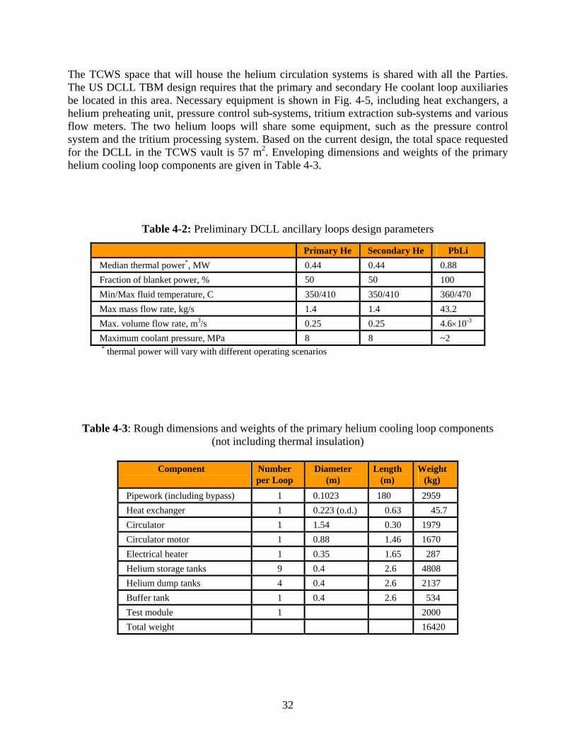
32
The TCWS space that will house the helium circulation systems is shared with all the Parties. The US DCLL TBM design requires that the primary and secondary He coolant loop auxiliaries be located in this area. Necessary equipment is shown in Fig. 4-5, including heat exchangers, a helium preheating unit, pressure control sub-systems, tritium extraction sub-systems and various flow meters. The two helium loops will share some equipment, such as the pressure control system and the tritium processing system. Based on the current design, the total space requested for the DCLL in the TCWS vault is 57 m2. Enveloping dimensions and weights of the primary helium cooling loop components are given in Table 4-3.
Table 4-2: Preliminary DCLL ancillary loops design parameters
Primary He Secondary He PbLi Median thermal power*, MW 0.44 0.44 0.88 Fraction of blanket power, % 50 50 100 Min/Max fluid temperature, C 350/410 350/410 360/470 Max mass flow rate, kg/s 1.4 1.4 43.2 Max. volume flow rate, m3/s 0.25 0.25 4.6×10⁻³ Maximum coolant pressure, MPa 8 8 ~2
* thermal power will vary with different operating scenarios
Table 4-3: Rough dimensions and weights of the primary helium cooling loop components (not including thermal insulation)
Component
Number per Loop
Diameter (m)
Length (m)
Weight (kg)
Pipework (including bypass) 1 0.1023 180 2959 Heat exchanger 1 0.223 (o.d.) 0.63 45.7 Circulator 1 1.54 0.30 1979 Circulator motor 1 0.88 1.46 1670 Electrical heater 1 0.35 1.65 287 Helium storage tanks 9 0.4 2.6 4808 Helium dump tanks 4 0.4 2.6 2137 Buffer tank 1 0.4 2.6 534 Test module 1 2000 Total weight 16420
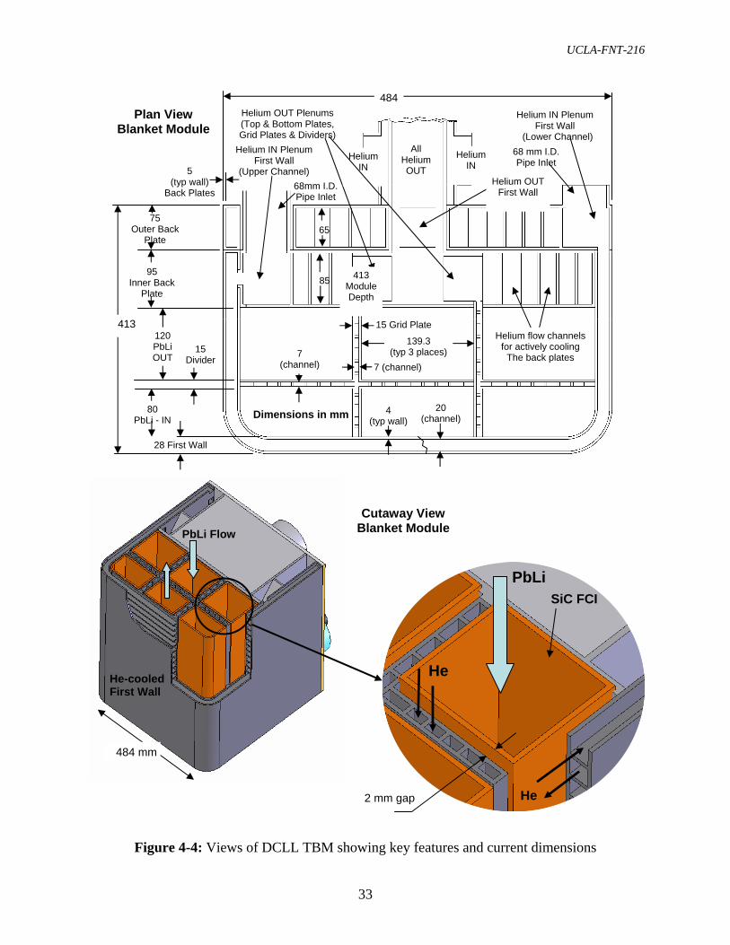
UCLA-FNT-216
33
Figure 4-4: Views of DCLL TBM showing key features and current dimensions
PbLi Flow
He-cooled First Wall
PbLi
He
He
SiC FCI
2 mm gap
484 mm
Cutaway View Blanket Module
15 Divider
28 First Wall
95 Inner Back
Plate
4 (typ wall)
20 (channel)
7 (channel)
120 PbLi OUT
80 PbLi - IN
484
Helium IN Plenum First Wall
(Upper Channel)
Helium IN Plenum First Wall
(Lower Channel)
139.3 (typ 3 places)
Helium OUT Plenums (Top & Bottom Plates, Grid Plates & Dividers)
15 Grid Plate
7 (channel)
75 Outer Back
Plate
Helium OUT First Wall
Helium IN
Helium IN
All Helium OUT 5
(typ wall) Back Plates
65
85
Helium flow channels for actively cooling
The back plates
Dimensions in mm
Plan View Blanket Module
68mm I.D. Pipe Inlet
68 mm I.D. Pipe Inlet
413 Module Depth
413
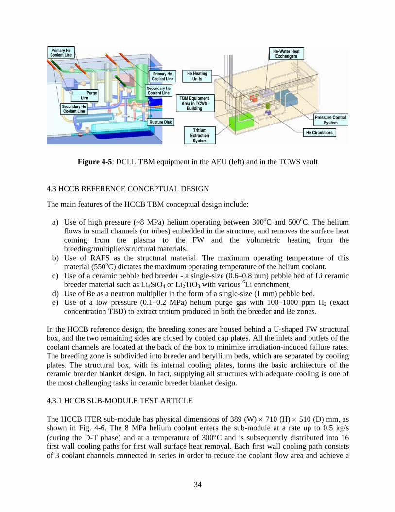
34
Figure 4-5: DCLL TBM equipment in the AEU (left) and in the TCWS vault 4.3 HCCB REFERENCE CONCEPTUAL DESIGN The main features of the HCCB TBM conceptual design include:
a) Use of high pressure (~8 MPa) helium operating between 300oC and 500oC. The helium flows in small channels (or tubes) embedded in the structure, and removes the surface heat coming from the plasma to the FW and the volumetric heating from the breeding/multiplier/structural materials.
b) Use of RAFS as the structural material. The maximum operating temperature of this material (550oC) dictates the maximum operating temperature of the helium coolant.
c) Use of a ceramic pebble bed breeder - a single-size (0.6–0.8 mm) pebble bed of Li ceramic breeder material such as Li4SiO4 or Li2TiO3 with various 6Li enrichment.
d) Use of Be as a neutron multiplier in the form of a single-size (1 mm) pebble bed. e) Use of a low pressure (0.1–0.2 MPa) helium purge gas with 100–1000 ppm H2 (exact
concentration TBD) to extract tritium produced in both the breeder and Be zones. In the HCCB reference design, the breeding zones are housed behind a U-shaped FW structural box, and the two remaining sides are closed by cooled cap plates. All the inlets and outlets of the coolant channels are located at the back of the box to minimize irradiation-induced failure rates. The breeding zone is subdivided into breeder and beryllium beds, which are separated by cooling plates. The structural box, with its internal cooling plates, forms the basic architecture of the ceramic breeder blanket design. In fact, supplying all structures with adequate cooling is one of the most challenging tasks in ceramic breeder blanket design. 4.3.1 HCCB SUB-MODULE TEST ARTICLE The HCCB ITER sub-module has physical dimensions of 389 (W) × 710 (H) × 510 (D) mm, as shown in Fig. 4-6. The 8 MPa helium coolant enters the sub-module at a rate up to 0.5 kg/s (during the D-T phase) and at a temperature of 300°C and is subsequently distributed into 16 first wall cooling paths for first wall surface heat removal. Each first wall cooling path consists of 3 coolant channels connected in series in order to reduce the coolant flow area and achieve a

UCLA-FNT-216
35
high helium velocity. A relatively high flow rate (and velocity) is needed to ensure an adequately high heat transfer coefficient for removing the unpredictably high local surface heat load of up to 0.5 MW/m2. The overall first wall thickness is 25.5 mm, including a square coolant tube of 11 × 11 mm2 with a wall thickness of 1.5 mm, a front wall plate of 4 mm, and a back wall plate of 7.5 mm. The flow rate of 0.5 kg/s gives a lower coolant outlet temperature, as compared to the typical value of 500°C needed for achieving high thermal efficiency in helium-cooled ferritic steel blanket designs; thus, about 40% of the flow is by-passed away from the breeding zones after the first wall cooling. The remaining coolant in the sub-module is divided into four paths for cooling the top and bottom side walls and the breeding zones. Thermo-fluid helium flow and heat transfer analysis is being performed to design the flow supply and collector manifold. As shown in Fig. 4-7, analysis reveals that the flow is not uniformly distributed; the third helium flow path has less flow and thus is hotter than other two FW coolant paths, as it is heated by the surface heat flux. Two geometrical configurations of the breeding zones are currently planned for testing in one sub-module. In one configuration, the planes of both the beryllium and breeder beds are perpendicular to the FW, facing the plasma region. An exploded view of the sub-module for this design configuration is shown in Fig. 4-8. In the other configuration, the pebble bed planes are parallel to and layered behind the FW. This option resembles the blanket concept considered in the US ARIES-CS and High Average Power Laser (HAPL) designs [4-5, 4-6]. The final selection of the HCCB sub-module configuration depends on the ease of fabricating the cooling plate. A complete sub-module will use 50 kg of breeder material, 43.2 kg of beryllium, and about 502 kg of RAFS. However, only a fraction of the breeding zones of the first EM test sub-module will be filled with breeder and beryllium pebble materials, in order to study the effect of transient impulses caused by plasma disruptions on pebble integrity. The helium purge gas running through the filled regions can be used to detect any changes in the pressure drop over time. 4.3.2 HCCB ANCILLARY EQUIPMENT The US HCCB reference strategy relies upon an international collaboration, under which the US would contribute to the fabrication and assembly of the shared ancillary equipment, including helium coolant, purge and tritium systems, at a fixed percentage of the total cost to be defined by agreement. Furthermore, it has been suggested that because of the limited space available in the TCWS, a common helium coolant system and associated helium purification system may be constructed for all the modules housed in Port 16 (or even for all helium-cooled ceramic/solid breeder TBMs). It is estimated that the US sub-module will have He coolant and purge gas characteristics that are very similar to those of other sub-modules in Port 16. Assuming that, due to space availability at the TCWS vault, only one helium coolant system per port is allowed, the main helium coolant flow will be divided into a number of cooling streams to feed various sub-modules (including the US HCCB sub-module) in the AEU

36
Figure 4-6: Stand-alone view of conceptual US HCCB sub-module (710 × 389 × 510 mm)
Figure 4-7: Calculated He velocity and temperature characteristics in FW and breeding zone
cooling plates (design analysis in progress)
Beryllium Pebble Bed Solid Breeder Pebble Bed Coolant Channel
He in
FW
He out
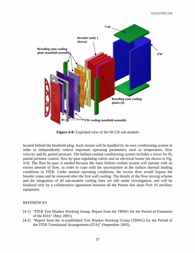
UCLA-FNT-216
37
Figure 4-8: Exploded view of the HCCB sub-module
located behind the bioshield plug. Each stream will be handled by its own conditioning system in order to independently control important operating parameters, such as temperature, flow velocity and H2 partial pressure. The helium coolant conditioning system includes a mixer for H2 partial pressure control, flow by-pass regulating valves and an electrical heater (as shown in Fig. 4-9). The flow by-pass is needed because the main helium coolant system will operate with an excess amount of flow, in order to cope with the uncertainties in the surface thermal loading conditions in ITER. Under normal operating conditions, the excess flow would bypass the breeder zones and be removed after the first wall cooling. The details of the flow mixing scheme and the integration of all sub-module cooling lines are still under investigation, and will be finalized only by a collaborative agreement between all the Parties that share Port 16 ancillary equipment. REFERENCES [4-1] “ITER Test Blanket Working Group, Report from the TBWG for the Period of Extension
of the EDA” (May 2001). [4-2] “Report from the re-established Test Blanket Working Group (TBWG) for the Period of
the ITER Transitional Arrangements (ITA)” (September 2005).
FW
Breeding zone cooling plates (4)
Breeding zone cooling plate manifold assembly
Cap
Breeder (only 1 shown)
FW cooling manifold assembly

38
Figure 4-9: Port and port cell layout of ancillary conditioning equipment and measurement systems for the HCCB test sub-module. (Illustration only. Details of the ancillary equipment
arrangement in the port cell have yet to be coordinated with collaborating Parties.)
[4-3] C.P.C. Wong, A. Ying, M. Abdou, A. Abou-Sena, Z. An, J. Blanchard, P. Calderoni, D.P. Carosella, M. Dagher, J. El-Awady, P.J. Fogarty, N. Ghoniem, E. Kim, R. Kurtz, M.P. Labar, S. Majumdar, S. Malang, B. Merrill, N.B. Morley, S. Reyes, M. Sawan, S. Sharafat, S. Smolentsev, G. Sviatoslavsky, D.K. Sze, M. Ulrickson, R.S. Willms, M. Youssef, S.J. Zinkle, Design Description Document for the U.S. Dual-Coolant Pb-17Li (DCLL) Test Blanket Module Report to the ITER Test Blanket Working Group (TBWG), UCLA Report UCLA-FNT-212, General Atomics Report GA-C25027, Rev. 3, 196 pages (November 2005).
[4-4] C.P.C Wong, M. Abdou, D.P. Carosella, M. Dagher, M.P. Labar, S. Malang, B. Merrill, N. Morley, M. Sawan, R.S. Willms, D-K Sze, Ancillary systems for dual coolant liquid breeder test blanket modules – Interim report to the ITER Test Blanket Working Group (TBWG), UCLA-FNT-195, General Atomics Report GA–A24754, 83 pages, (July 2004).
[4-5] A.R. Raffray, S. Malang, L. El-Guebaly, X. Wang and the ARIES Team, “Ceramic Breeder Blanket for ARIES-CS,” Fusion Science & Technology, vol. 47/4, pp. 1068-1073 (2005).
[4-6] M.E. Sawan, I.N. Sviatoslavsky, A.R. Raffray, and X. Wang, “Neutronics Assessment of Blanket Options for the HAPL Laser Inertial Fusion Energy Chamber,” proceedings of the 21st IEEE/NPSS Symposium on Fusion Engineering, Knoxville, TN, Sept. 26-29, (2005).
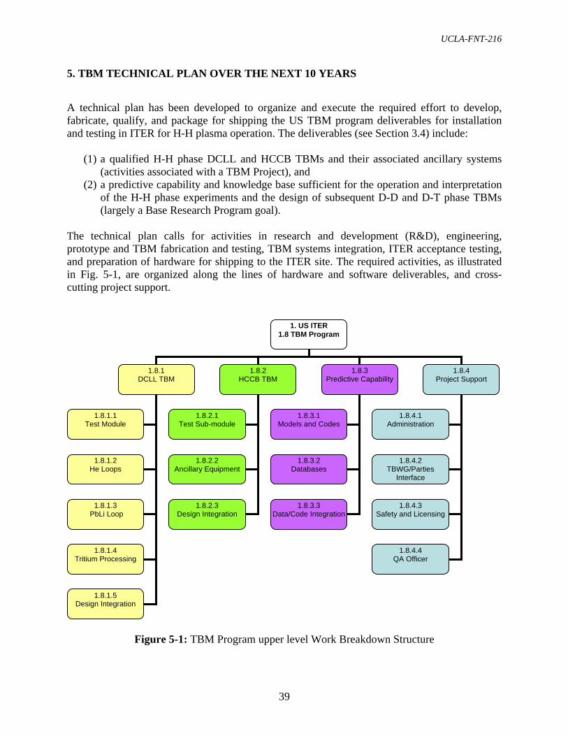
UCLA-FNT-216
39
5. TBM TECHNICAL PLAN OVER THE NEXT 10 YEARS A technical plan has been developed to organize and execute the required effort to develop, fabricate, qualify, and package for shipping the US TBM program deliverables for installation and testing in ITER for H-H plasma operation. The deliverables (see Section 3.4) include:
(1) a qualified H-H phase DCLL and HCCB TBMs and their associated ancillary systems (activities associated with a TBM Project), and
(2) a predictive capability and knowledge base sufficient for the operation and interpretation of the H-H phase experiments and the design of subsequent D-D and D-T phase TBMs (largely a Base Research Program goal).
The technical plan calls for activities in research and development (R&D), engineering, prototype and TBM fabrication and testing, TBM systems integration, ITER acceptance testing, and preparation of hardware for shipping to the ITER site. The required activities, as illustrated in Fig. 5-1, are organized along the lines of hardware and software deliverables, and cross-cutting project support.
Figure 5-1: TBM Program upper level Work Breakdown Structure
1. US ITER 1.8 TBM Program
1.8.1 DCLL TBM
1.8.2 HCCB TBM
1.8.3 Predictive Capability
1.8.1.1 Test Module
1.8.1.2 He Loops
1.8.1.3 PbLi Loop
1.8.1.4 Tritium Processing
1.8.1.5 Design Integration
1.8.2.1 Test Sub-module
1.8.2.2 Ancillary Equipment
1.8.2.3 Design Integration
1.8.3.1 Models and Codes
1.8.3.2 Databases
1.8.3.3 Data/Code Integration
1.8.4 Project Support
1.8.4.1 Administration
1.8.4.2 TBWG/Parties
Interface
1.8.4.3 Safety and Licensing
1.8.4.4 QA Officer
40
The US TBM technical plan described here is based on:
• the ITER testing strategy, assumptions, and deliverables outlined in Chapter 3e; • the conceptual TBM designs described in Chapter 4, which show the basic geometry and
parameters of the TBMs and the supporting ancillary loops and equipment; • any restrictions or considerations owing to environmental, health and safety requirements
for R&D and testing with hazardous materials such as Be, Pb, and Li. • the principle that a primary function of the H-H module and testing is to explore and
verify the design fabrication, operation, diagnosis and control of the TBMs and ancillary systems before the beginning of the D-D and D-T nuclear operation phases in ITER, when remote handling will be required (i.e., the H-H phase TBMs could be considered as prototypes of the nuclear phase TBMs); and
• the need for flexibility, where the technical plan itself is intended to evolve as new information and understanding become available, impacted by R&D results, definitions of ITER licensing and acceptance criteria, and the interactions with vendors and international collaborators.
The DCLL and HCCB development and deployment activities will proceed in parallel to complete the first-generation hardware within the specified time period (by the end of March 2015). It is recognized that there is significant overlap between the DCLL and HCCB R&D needs, as well as in required design, analysis and testing capabilities. In the description of the technical development plans below, such joint or complementary activities are included in the DCLL description and only mentioned briefly in the appropriate HCCB context. 5.1 DUAL-COOLANT LEAD-LITHIUM (DCLL) TECHNICAL PLAN SUMMARY The selection of the DCLL concept by the US research team took place in 2004, and since then effort has been focused on developing a conceptual DCLL blanket design for reactor application [5-1] as well as a conceptual design of a TBM for integrated testing in ITER [5-2]. This work has led to the development of the DCLL “reference” conceptual design described in Chapter 4.2, and to the determination of the necessary fundamental R&D and engineering activities described here. The DCLL development plan further subdivides the work into 5 categories representing the four major DCLL sub-systems and an integration activity:
1. Test Blanket Module, up to the point where access pipes are cut during TBM change-out in ITER,
2. Helium Circulation Systems, including both the primary (to the TBM) and secondary (to the PbLi/He heat exchanger) systems,
3. PbLi Circulation System, including the PbLi/He heat exchanger, 4. Tritium Processing Systems, including tritium extraction hardware in contact with
helium and PbLi coolant streams, and
e The information presented in Chapters 3 and 4 is not repeated here except as needed for clarity of presentation.

UCLA-FNT-216
41
5. Design Integration for the TBM sub-systems and ITER interfaces, including pipe runs, connections, remote handling tools, AEUs, and corresponding monitoring systems.
Within each hardware sub-system, a plan is established to design, identify and resolve risks and R&D issues, and ultimately fabricate, test, and prepare to ship the hardware. The Design Integration task includes activities related to the interfacing of all the sub-systems of the reference DCLL TBM with each other and with the ITER machine, facilities and operation. This integration task includes both in-vessel and ex-vessel integration, along with installation, removal and replacement operations, maintenance, and facilities sharing with ITER and other TBM Parties in accordance with ITER design and operation, schedule, guidelines and requirements. Fig. 5-2 shows some of the major activities and logical information flow for the DCLL, driven mostly by the TBM design and fabrication schedule. (This figure is meant to illustrate the DCLL plan logic; more detailed Integrated Schedule information is available in Chapter 7 and in Ref. [5-3].) A separate effort for Safety and Regulatory Support to coordinate required licensing analysis and reporting for the DCLL TBM and ancillary equipment is included in the Project Support category. Various safety analyses not covered by the engineering design activities are included under this DCLL WBS.
Figure 5-2: Logical and temporal layout of activities for DCLL TBM development
TBM
Loop
sT
preliminary TBM detailed TBM title III / design revisions
MUs prototype
MUs
MUs proto 1st TBM QAfacilities
basic FCI and RAFS fab routes/irradiation
diagnostic/heat trans nuclear diagnostics / 2nd TBMR&D
Engr/Design
Fabrication
Testing
~FY07 – FY08 ~FY09 – FY10 ~FY11 – FY15
prototype
preliminary loops detailed loops title III
assembly
Operation
pumps/seals/valvesR&D
Engr/Design
Fabrication
Testing
components
HX
QA
models/data R&D
Engr/Design
extractor devel.
prelim. T sys detailed T sys
DI
connections R&D
Engr/Design
field joining
cask, control, RH title III
Fabrication
Testing
He cleanup
assembly
operation
components
QA
1st TBM
NDE/optimization
basic MHD

42
5.1.1 DCLL R&D The DCLL blanket will require research and development to establish:
• the detailed specifications for fabrication techniques and selected materials necessary for TBM designs;
• the diagnostic techniques for acquiring the data and enabling control under different operating conditions;
• an understanding of, and predictive capability with respect to, the behavior and control of the system, in both normal operation and in faulted conditions; and
• the database needed for the safety and qualification dossier. Table 5-1 provides a brief description of each of the main R&D categories. (A more detailed task breakdown is given in Appendix B, and a detailed R&D task description is available in Ref. [5-3].) These areas include tasks required for all the main DCLL categories mentioned above: TBM, He loops, PbLi loop, Tritium Systems, Design Integration, and Safety. These R&D activities are aimed at mitigating risk (see Chapter 9) due to uncertain TBM response during ITER testing, providing the database for verification of predictive capabilities as required by standard QA procedures, and providing important design, fabrication and safety information on specific issues or for specific components. It should also be noted that many R&D activities are common to many TBM concepts being proposed internationally. The possibilities for international collaborations on DCLL R&D issues are strong, and the likely benefits for the US are high. The development of reduced activation ferritic steel fabrication technology is the largest single R&D category. This category includes an intensive effort, in concert with industry, to develop and test the final material and fabrication specifications for the complex, thin-walled TBM designs that will be provided to the final vendor(s). Hot Isostatic Pressing (HIP), casting, welding technologies, and nondestructive evaluation techniques and procedures will be evaluated and developed. Early inclusion of industrial vendors is essential to take advantage of relevant industrial experience to accelerate the work and to ensure that the fabrication technologies are within the capability envelope of a wide range of vendors. To facilitate the early stages of fabrication technology development, when relatively large quantities of material will be needed, a surrogate steel such as T91, which has properties similar to RAF/M steels, will be utilized. As part of the R&D effort, more representative “partially-integrated” tests will be needed on scaled mockups in order to meet qualification requirements for “non-code” experimental components (see Section 3.3). This testing is to follow successful single and multiple effects tests. At present, three main partially integrated tests are considered necessary before the initiation of the first TBM fabrication.
Mockup FW heat flux testing – The objective of this test is to thermally load a helium-cooled TBM mockup with a simulated FW heat load in a succession of pulses characteristic of ITER operation. Acceptable helium flow characteristics, structural temperatures and deformation, and failure modes will be verified. An additional goal of this test is to develop additional experience with high
UCLA-FNT-216
43
temperature helium coolant loops and test any non-standard He flow loop components. PbLi flow and heat transfer test – The objective of this test is to verify the MHD PbLi pressure drop, flow distribution, heat transfer, and initial chemical compatibility characteristics in an integrated mockup containing all the geometric and material elements of the first TBM. The following elements will be included: inlet/outlet manifolds and FCIs, parallel poloidal channels and FCIs, helium cooled divider plates and walls, and coaxial PbLi inlet/outlet pipes and FCIs. An additional goal of this test is to address safe handling and practice preheating and uniform filling of the TBM with PbLi, as well as testing of any non-standard PbLi flow loop components.
Pressurization tests – The objective of this test is to test the response of a prototype mockup (see description below) to pressurization by the helium coolant and to mimic a breach of helium into the PbLi portion of the TBM. A certain over-pressurization (a factor of 1.25 is specified in the TBWG ITA Report) could be required, depending on final ITER acceptance test requirements.
As the ITER requirements are clarified, it is possible that the partially-integrated testing programs described above will need to be modified accordingly. The current plan proposes to utilize/modify existing US facilities whenever possible, including the Plasma Materials Test Facility (PMTF) at the Sandia National Laboratory and the Magneto-Thermofluid Omnibus Research (MTOR) Laboratory at UCLA. 5.1.2 DCLL ENGINEERING DESIGN AND ANALYSIS Consistent with DOE practice, the design of the first DCLL TBM is divided into three phases, denoted Preliminary (or Title I), Detailed (or Title II), and Final Design and Fabrication Support (or Title III). The Preliminary Design represents roughly 30%, and the Detailed Design roughly 70%, of the design effort. Title III, in addition to its more traditional role in support of the procurement and fabrication stages, will also include a mechanism to integrate any final design changes necessitated by the results of partially-integrated testing and late R&D results, and lessons learned during the fabrication of a prototype. The DCLL TBM design effort will center on the mechanical design and will be supported by engineering analyses of various types and the aforementioned R&D efforts. These design analyses include various levels of neutronics, LM-MHD and helium thermofluid, electromagnetic, structural, tritium permeation and system thermal-hydraulics analysis, including the external loop systems. Design iterations will be necessary to arrive at a final design that will achieve testing goals while meeting structural and temperature design limits and ITER Codes and Standards criteria. Yearly design reviews are planned for both the Preliminary and Detailed Design phases.

44
Table 5-1: DCLL R&D areas and their top level purpose and description
R&D Areas Key Questions Addressed by R&D Activity Description
Thermofluid MHD
How can uniform PbLi flow distribution between parallel channels be established? What are the structure, FCI and PbLi temperatures in the TBM during ITER operation and potential accident scenarios? What are the electrical and thermal property requirements for the FCI?
Obtain experimental database on key MHD flow elements affecting safe operation of the TBM for which there is little/no existing data
• Poloidal PbLi channel distribution manifolds. Data needed to allow design of manifold elements controlling PbLi flow distribution
• FCI effects on pressure drop and heat transfer. Data needed to determine pressure drop and heat transfer characteristics for basic SiC FCI and near FCI joints, pressure equalization holes, and flaws in order to set FCI and SiC design requirements
Obtain verified predictive capability for PbLi flow and heat transfer with extrapolation to ITER conditions. Code and model developments and verification activities using existing and new (above) experimental data in order to determine operational conditions in TBM for design-by-analysis effort.
SiC FCI Fabrication and Properties
What are the achievable SiC properties affecting FCI performance? What are the allowable thermal gradient and other loading conditions?
Obtain experimental database on the essential properties of SiC for FCIs (conductivities, strengths, failure modes, etc.) resulting for various proposed fabrication techniques.
• Develop testing procedures and apparatus • Produce and characterize 2 generations of samples
Develop technical specifications and prototypes of preferred FCI materials and fabrication techniques. Validate low dose irradiation resistance and properties of FCI.
SiC/FS/PbLi Compatibility & Chemistry
What are the temperature ranges of compatibility for the material systems proposed for the DCLL TBM?
Obtain experimental database on compatibility of materials used in the DCLL TBM system: static and flowing compatibility at 500ºC (and above where possible) especially to determine any dissimilar material effects between, e.g., FS and SiC. Evaluate material samples and mockups used in flowing thermofluid MHD integrated testing experiments. Establish recommendations for material temperature limits and effects.

UCLA-FNT-216
45
R&D Areas (Cont) Key Questions Addressed by R&D Activity Description
RAFS Steel Fabrication Development and Materials Properties
What structural material alloy specification should be used for the US TBMs? What fabrication techniques and procedures should be used for construction of the TBM? What material properties should be used for base metal and joints in the TBM design? What NDE tests and testing procedures should be used to verify TBM acceptance? What specialty RH equipment is needed for cutting/rewelding TBM access piping?
Develop material specifications and oversee fabrication of mockups for partially integrated mockup testing. Obtain experimental database on HIP and Investment casting fabrication of RAFS samples and mockups, including dimensional tolerances and mechanical properties. Develop detailed database on primary fabrication route (HIP or IC) using TBM-like RAFS samples and mockups, including dimensional tolerances and mechanical properties, for process and material qualification with ITER. Develop joining procedures, test methodology and obtain experimental database of joint samples for TBM, including mechanical properties and effects of low dose irradiation, for process and material qualification with ITER.
Develop procedure and standard samples for validation of NDE testing methods for final TBM qualification with ITER. Develop procedure and property database for field cutting/welding of FS piping, and forming co-axial FS interior slip fit joints (under DI 1.8.1.5).
Helium System Subcomponents Analyses and Tests
What are the structure temperatures in the TBM during ITER operation?
Obtain experimental database and correlations for key helium flow issues affecting safe operation of the TBM.
• Flow distribution in proposed manifold designs • Quantification of heat transfer coefficient and pressure drop with
proposed roughening
PbLi/H2O H2 Prod What volume of PbLi can be used in the DCLL experimental system?
Obtain an experimental database and correlation for the percentage of reacted Li during PbLi/Water reactions under projected ITER accident conditions using most appropriate PbLi/water contact modes.

46
R&D Areas (Cont) Key Questions Addressed by R&D Activity Description
Be Joining to RAFS for FW Armor
What joining procedure can be used to attach the required Be armor to TBM FW? What thermal and mechanical properties of the Be/RAFS joint should be used in the TBM design and analysis?
Develop proposed attachment techniques for Be joining to RAFS as required by ITER for all TBMs.
Develop test procedures, test samples, and obtain preliminary experimental database of mechanical and thermal properties of joints for candidate joining methods. Test initial irradiation resistance of the joint.
Prepare and test small and medium scale mockups for testing high heat flux testing facility for thermal cycle resistance. Optimize joining procedures
TBM Diagnostic Development
What diagnostics can be used successfully in the TBM environment? What are the attachment procedures, deployment systems, and typical failure modes for nuclear and non-nuclear diagnostic systems?
Develop/modify existing diagnostic transducers/insulation/attachments for TBM operation including high temperature, PbLi compatibility, tokamak field compatibility, neutron/gamma irradiation, and small size. Typical transducers include thermocouples, strain gauges, sensors, current coils and voltage probes, pressure sensors, etc.
Deploy and test transducers and systems on various mockup tests and in tokamak experiments. Modify DAC filters and attachments as needed.
Identify and test nuclear field diagnostics for D-D phase TBM in international test consortium using international 14 MeV neutron facilities.
Tritium Control (under Tritium Processing Systems, 1.8.1.4)
What tube length, materials, etc., should be used in the design of the tritium vacuum permeator system? What will be the tritium permeation into the He coolant, and what measures will be required to remove it?. Is secondary tritium containment around pipes / equipment required to meet ITER release restrictions?
Obtain experimental database on fundamental tritium issues affecting inventory and permeation:
• Solubility, rate constants in PbLi alloy / FS material systems • tritium extraction from PbLi using vacuum permeator system with
various materials and gas conditions • tritium extraction from He using candidate technologies for He
cleanup (TBD) Obtain verified predictive capability for tritium permeation with extrapolation to ITER conditions. Code and model developments and verification activities using existing and new (above) experimental data in order to determine operational conditions in TBM and ancillary systems.
Partially-Integrated Mockup Tests
Will first-of-a-kind systems behave as anticipated in ITER conditions?
Obtain design-by-analysis verification of key integrated systems as needed for acceptance of non-code-qualified, unique components in ITER (see detailed description in main text)

UCLA-FNT-216
47
Full circulation He and PbLi loops will also be designed, fabricated, and deployed for the H-H phase to support the TBM operation. These ancillary systems will be fully tested, and operational procedures determined, prior to ITER operation. The corresponding ancillary systems will be designed to the operational and testing requirements of the first 10 years of ITER operation, covering the sequence of testing phases. The design of the components in the ancillary helium flow loops will be based on existing helium coolant and control technologies developed for fission reactors. Still, some first-of-a-kind components are anticipated. These non-standard components will be tested in the reduced scale He flow loop utilized for FW heat flux mockup testing (described above). Ancillary helium flow loop components will be located in the TCWS vault, and connected to the port cell area with thermally insulated piping. The need to prevent tritium permeation from the helium to the building atmosphere or the tokamak cooling water during later D-T operation will be included in the design effort. It should be noted that the helium loops proposed by nearly all Parties have very similar parameters, so that a coordinated effort and procurement could benefit the US. The design of the PbLi circulation system will utilize experience in the circulation of various lead alloys for advanced fission reactor development, and expertise on the circulation of other heavy metal alloys, like mercury, that exists in US National Laboratories and industry. Materials in contact with the PbLi must be compatible to 470°C, and so some version of 9- to 12-Cr ferritic steel, such as T91 is favored for exterior loop components. It is anticipated that the pump could be available commercially with minimum modification, but some design and analysis effort will be required for the PbLi/He heat exchanger and any custom purification equipment, like cold traps, for the PbLi. Similar to the helium flow loops, non-standard components will be tested as part of the PbLi flow loop constructed for MHD thermofluid mockup testing, and the potential for tritium permeation and the needs for secondary containment will be established and integrated into the design. The tritium processing system will be composed of individual sub-systems that process multiple effluents from different parts of the TBM system. Tritium extraction and processing systems for the PbLi, two helium loops, and possibly secondary containment atmosphere must all be designed. Expertise on such processing exists in US National Laboratories and internationally, but it is anticipated that a non-negligible design and analysis effort, coupled to R&D described above, will be required, as these systems all require extrapolations of present knowledge to new conditions. Tritium processing will not be needed during the H-H phase testing, although it is desired to have the tritium systems completed, at the latest, in year 3 of H-H operation so that they can be fully tested during the D-D operation. There are two design integration task categories: (1) the integration of different DCLL sub-systems, e.g., co-axial piping and bellows connecting the TBM in the ITER port to the PbLi loop system located in the port cell area; and (2) the integration between the DCLL systems with the facility, operation and schedule of ITER. These design integration tasks are essential for the acceptance and efficient operation of the DCLL test program in ITER. They involve the interaction between all sub-systems interfaces, or between sub-systems and ITER, making sure adequate communication is in place to ensure compatible dimensions, materials, attachments interfaces, and assembly procedures compatible with remote handling equipment, etc.

48
5.1.3 DCLL FABRICATION AND QUALIFICATION The fabrication and qualification sequence for the TBM is subdivided into the fabrication of a full scale prototype and then the first TBM. Both the prototype and the first TBM will be fabricated by industry vendors and will undergo the normal steps of contract announcement, bidding, contract award; material procurement and tooling; subcomponent fabrication and NDE; final assembly and NDE; and any other acceptance tests to be specified by the DCLL program to meet ITER requirements. These activities are supported and directed under the Title III design described above. However, the specific fabrication methods for the selected materials and components are to be developed under material R&D activities presented earlier. It is intended to construct the prototype using the same design, materials, and fabrication techniques identified in the Detailed Design (Title II) phase in order to make a true practice attempt at fabricating the first-of-a-kind TBM. The prototype will then be subjected to various NDE acceptance tests and pressurization tests to determine any weaknesses or flaws. Mandated qualification and acceptance tests specified by ITER will also be performed on the prototype module. Results of the tests will feed back into finalizing the design and fabrication processes for the first TBM. The prototype, if fully functional and undamaged, could potentially be used as a spare TBM during ITER H-H testing should the primary TBM fail. Similarly, the prototype could potentially be re-fitted to serve as a mockup for extending partially-integrated testing in various facilities or as a mockup for testing nuclear diagnostics for the second (D-D phase) TBM. If the prototype is damaged, destructive evaluation of the prototype will be required in order to fully diagnose and understand the failure. The first TBM for the ITER H-H phase will be fabricated based on the Final Design (Title III) which will integrate changes mandated by the results of the Prototype and partially-integrated mockup tests, and any late R&D results. The ITER H-H phase DCLL TBM must pass all ITER mandated qualification and acceptance tests (still to be officially determined) and be fully documented in the safety and qualification dossiers. Each sub-component and the final TBM will be subjected to a series of non-destructive evaluations to validate joint integrity, absence of leaks, and limited thermal performance. The completed, tested, and qualified TBM will then be packaged and prepared for shipment to the ITER site for installation. Similarly, the components of the ancillary systems will be fabricated, assembled and tested according to ITER requirements. The fabrication sequences of the ancillary loops are not expected to be as time-consuming as those for the first TBM, and have not yet been planned in great detail. Still, the shipment of these components could be earlier than the first TBM due to the expected longer setup and testing time for both helium loops and PbLi loop systems. 5.2 HELIUM COOLED CERAMIC BREEDER (HCCB) TECHNICAL PLAN SUMMARY The HCCB technical plan is divided into the activities necessary to provide the three main deliverables:

UCLA-FNT-216
49
1. HCCB sub-module, up to the point where inlet/outlet pipes are welded to the common manifold plate,
2. Ancillary Systems, including mainly the helium coolant system, 3. Design Integration, to coordinate TBM supporting systems and ITER interfaces.
The design integration activity includes interactions with the participating Parties and ITER IO that are necessary for the integration of the US HCCB test sub-module into the half-port module, and for the integration of ancillary equipment and associated measuring systems into the ITER plant. The activities also include developing and documenting interface issues and requirements and facilities sharing in accordance with ITER design and operation guidelines and requirements, as well as contributing to design, layout, and procurement of the US specific components needed for the integration in the port cell. The integration also includes providing independent instrumentation with data connection to the CODAC system through a local controller. The US sub-module will use the same ancillary equipment as the host, including the helium coolant loop and tritium processing systems. This approach requires strong cooperation among the US and the host Party in the loop design and in the acquisition and fabrication of components. Additionally, design, manufacturing, and testing of “common” TBM elements are required, particularly in the areas of the supporting structure, helium flow distribution, and the collection manifold. The HCCB technical plan presented here is focused mainly on producing the first sub-module, which is based on the HCCB “reference” conceptual design described in Chapter 4.3. In addition to providing proof-of-performance data for subsequent nuclear ITER test sub-modules, the H-H sub-module addresses the critical issue of the structural thermomechanical response of a blanket component under normal and off-normal operations. It is equipped with instrumentation to measure forces acting on the TBM and the mechanical response of the TBM structure to transient EM loads, and to provide data on the effect of the ferritic steel structure on the magnetic fields within ITER. 5.2.1 HCCB RESEARCH AND ENGINEERING DEVELOPMENT The R&D defined in the HCCB program is targeted to gain the critical data required to design, fabricate and operate HCCB sub-modules that will (a) address tritium generation and high grade heat extraction issues and (b) satisfy ITER safety and qualification criteria [5-4, 5-5]. Required R&D activities and testing facilities for the HCCB that are also required for the US DCLL are included under the DCLL sections of this report. Such “dual use” activities include the development of structural material and fabrication techniques and irradiation database, Be/RAFS joining at the first wall, any testing facility needed to perform first wall heat transfer and structural deformations, vacuum leak and pressurization, NDE, and helium flow thermal-hydraulic tests, etc. In addition, similar R&D on the structure and associated fabrication are underway in the EU and Japan, and the US HCCB program can potentially leverage these efforts through appropriate collaboration. The US HCCB R&D is broken down into eight sub-tasks that fall within the following categories:
50
1. database for fabrication, material properties, and tritium permeation, 2. solid breeder pebble bed thermomechanics, temperature control and performance
R&D, and 3. partially integrated tests.
These R&D tasks, described in Table 5-2, represent only the most critically needed research over the next ten years. This R&D effort does not completely prepare the US to fabricate an independent HCCB sub-module, but rather to adequately feed into H-H phase TBM activities that support design, material procurement, operating conditions definition, and international collaboration. This modest effort allows the US to gain access to R&D results from the larger international programs in Japan and the EU under existing International Energy Agency (IEA) collaborations, and access to burgeoning programs in China and Korea under new collaborations. Fig. 5-3 illustrates the logical flow of the technical plan; showing when the R&D results feed into different phases of activities, and emphasizing that HCCB delivery to the host party is at the beginning of 2014, in order to support host Party integration and module acceptance tests. This later requirement makes the early definition of a HCCB collaboration/partner by DOE critical. It also puts extreme pressure on the HCCB prototype testing schedule. A more detailed description of R&D subtasks and scheduling details is available in Volume II of this report [5-3]. Under the present strategy, there will be no R&D for fabrication of ceramic breeder material in the US over the next 10 years. Instead, the US will evaluate the on-going breeder pebble fabrication R&D in the EU and Japan for use in the US H-H phase sub-module. It may be possible to establish a collaborative effort with a new ITER party, such as China or Korea, in this area of ceramic breeder pebble material fabrication and characterization, including microstructures, pebble size, 6Li enrichments, and the appropriate fabrication processes. Along with this evaluation, pebble bed thermomechanics and temperature control, as well as in-pile pebble bed assembly testing, will be undertaken in order to develop a verified materials properties database and associated predictive capabilities for the design and materials procurement efforts for the US HCCB sub-modules. The experimental study of, and model development for, ceramic breeder pebble bed thermo-mechanical performance is a key area for US contribution. Partially integrated testing of representative sub-module mockups is also planned, to be performed in the same test facilities already described for the DCLL. 5.2.2 HCCB ENGINEERING DESIGN AND ANALYSIS The HCCB Engineering Design phase is intended to transform goals and requirements into complete, detailed specifications for the test article to be constructed during the Fabrication phase. The Engineering Design includes a preliminary design in which the concept is solidified to meet the requirements, while technical uncertainties are resolved through computational analysis and research and development including small scale testing. The areas that need to be modeled for the H-H phase sub-module are first wall heat transfer, helium coolant flow distribution, structural and thermomechanics analysis, and electromagnetic analysis. The design analysis should take into account the need for a uniform flow distribution among the three sub-modules and structural support with respect to EM disruption loadings. Fabrication methods for

UCLA-FNT-216
51
the first wall structural box should be identified during this phase of activity. A design review is planned at the end of this preliminary design phase, in which progress, technical accuracy and risks of the selected design approach will be examined before the start of Detailed Design. The Detailed Design phase proceeds to resolve the gaps in the design information by more detailed analysis and prototype testing. The Detailed Design package includes technical specifications and requirements, fabrication drawings and procedures, material specifications, quality assurance requirements, acceptance criteria, testing specifications and requirements, and instrument schematics and wiring diagrams. In addition, any necessary test equipment and assembly and test procedures should be identified. The Title III activity includes supervision of the procurement and fabrication of the prototype and sub-module, and incorporates any final design changes by the results of partially-integrated testing and prototype tests.
Figure 5-3: HCCB schedule showing critical R&D feeding in to H-H phase TBM activities: design, material procurement, operating conditions definition, and international collaboration
HCCB Test Blanket Program Project 2005 2006 2007 2008 2009 2010 2011 2012 2013 2014 2015 2016
Program Porject Support
Test Blanket SubModule R&D
Helium flow distribution and manifold testing
Pebble bed thermomechanics & Temp Contrl
RAFS fabrication development
T-control and predictive capabilityBreeder pebble knowledge base & procurement specifications
Diagnostics and instrumentation (EM and NT)
Partially Integrated Tests
In-pile pebble bed assembly test
Engineering Preliminary Design
Detailed Design
Title III
Prototype & Submodule Fabrication & TestingContract Award
Material ProcurementTooling & ProcessingPrototype Fabrication Prototype qualification testsSubmodule Material ProcurementSubmodule FabricationSubmodule acceptance tests
TBM Integration & Shipping to ITERHost Party Integration and Module acceptance testsPackaging
First plasma
1st ConcretePrS report
CD4

52
Table 5-2: HCCB R&D areas and their top level purpose and description
R&D Areas Main Purpose over the next 10-years of R&D
He Flow & Manifold Tests
Obtain experimental database and simulation verification for key helium flow issues affecting safe operation of the TBM, particularly the flow distribution in proposed manifold designs. .
Ceramic Breeder Thermomechanics & Tritium Recovery
Obtain experimental database and fitted constitutive equations for thermo-physical properties of ceramic breeder packed pebble beds under thermal and mechanical loads typical of the various phases of ITER.
Verification of simulation tool for large-scale pebble bed thermomechanics analysis, and definition of initial mechanical loading conditions during packing assembly.
RAFS Fabrication Development
Development of best-suited RAFS fabrication and evaluation techniques for TBM components, and measurements for the properties database. (Resources and activities are covered under the DCLL)
Tritium Control and Predictive Capability
Development and experimental verification of predictive capability for the tritium permeation in configurations relevant to HCCB designs, including:
• the establishment of a database of material properties such as tritium (deuterium) solubility and permeability at lower pressure regimes (<100 Pa) under flow conditions; and
• the experimental investigation of the effect of isotope swamping and velocity profile on the permeation rate.
Definition and experimental verification of purge gas composition and flow conditions for the candidate ceramic materials within which the permeation rate from the pebble bed to the helium coolant is acceptable.
Breeder Pebble Knowledge Base and Procurement Specs
Evaluation of the on-going breeder pebble fabrication R&D in EU and JA as a pebble material source for the US Confirmation of the breeder material procurement decision and evaluation of initial microstructure and thermophysical properties, especially those affecting the thermal performance and unacceptable tritium release behaviors.
Diagnostics and Instrumentation
Develop/modify existing diagnostic transducers including insulation/attachments to TBM, high temperature, deployment in packed beds, tokamak magnetic field compatibility, neutron/gamma irradiation, and small size. Typical transducers include thermocouples, strain gauges, hall sensors, current coils and voltage probes, pressure sensors, etc.
Partially Integrated Tests
Obtain design-by-analysis verification of key integrated systems as needed for acceptance of non-code-qualified, unique components in ITER. HCCB partially integrated testing will include:
• Helium flow distribution, FW heat transfer, and thermal cycling • HCCB Prototype over-pressurization tests
UCLA-FNT-216
53
5.2.3 HCCB FABRICATION AND QUALIFICATION The HCCB Fabrication and Qualification phase begins with the preparation of bid documents, selection of contractors, and negotiation of contracts for the prototype and TBM fabrications. The prototype is meant to verify design concepts and fabrication approaches. The prototype represents a full-scale model of the first HCCB test sub-module; however, surrogate pebble materials can be used to simulate the breeding and beryllium pebble materials. The prototype will be tested against its surface heat removal capability and pressure and leak testing. The test phase ensures that the prototype will perform as expected and will adhere to the pre-defined design parameters. Various NDE tests will be performed during the fabrication to detect surface and internal discontinuities in materials, welds and fabricated parts and components. The test results will help to determine the acceptability of (and/or any modifications needed on) the fabrication processes adopted for the TBM. Similar fabrication steps and NDE will be used to fabricate the sub-module TBM. The US sub-module will be prepared for shipping to the Host Party for the half-port test module integration, with the appropriate support from the US team. From there, the whole assembly will be shipped to ITER for on-site integration and installation. It is estimated that the US sub-module must be shipped to the host Party approximately one year prior to the 18-month ITER integration period, in order to allow sufficient time for both integration processes. 5.3 PREDICTIVE CAPABILITY TECHNICAL PLAN From a broad perspective, an ultimate goal of R&D and ITER testing is to provide a verified predictive capability (PC) that can enable the design and performance prediction of blankets for devices following ITER, including DEMO and fusion power plants. The development and verification of a predictive capability must therefore be recognized as central elements in the ITER TBM program. Equally important is the critical role of the PC in enabling a successful TBM program. A sufficient PC must be developed now in order to:
1. perform the analysis required for the design and qualification of any TBM in ITER, and 2. enable interpretation of experimental results from laboratory experiments and from ITER
TBMs. For these reasons, a verified predictive capability is considered a top level deliverable, and is included as a main branch in the WBS shown in Fig. 5-1. The required work is organized into 3 main categories described below. 5.3.1. MODELS AND CODES The technical plan calls for effort in code development in several areas critical to TBM function and safety, including most notably incompressible thermofluid MHD, tritium permeation, and pebble bed thermomechanics. New and better codes and phenomenological models are needed in these unique areas to help determine the basic operating conditions and loads inside the TBMs.

54
In addition to new codes, sophisticated solid models for input into existing neutronics, structural analysis, and thermal-hydraulics codes must also be developed and employed. These efforts are organized such that they appear under the R&D and engineering categories of the various systems where they are most needed, as well as appearing in the PC WBS. This is done because of the dual nature of these tasks. They are critical for the design and qualification of the TBMs, but also represent key deliverables for utilizing the TBMs effectively. Resources are included under the respective R&D and engineering categories and are not double-counted. The basic model and code development is largely considered a Base Program activity, while the code validation, verification, and application to the TBM is considered a TBM Project task. 5.3.2 DATA AND DATABASES New data and databases needed for TBM development, qualification, and operation have also been identified. In particular, data on pebble bed effective thermophysical and mechanical properties, RAFS base metal and joint properties; FCI-tailored SiC thermal, electrical and mechanical properties, tritium solubility in, and permeation from, PbLi, etc., are all critically needed. Again, these tasks are considered in the technical plan as shared responsibilities between the various DCLL and HCCB R&D and engineering efforts, and the PC effort. Resources are included under the respective R&D and engineering categories and are not double-counted. Individual judgment is used in each WBS to determine whether a particular activity is classified as Base Program or a TBM Project task. 5.3.3 DATA/CODES INTEGRATION Finally, an effort is planned to integrate the various PC tools and data (described above) into the most effective, coupled suite of capabilities possible. Such a suite must be able to exchange data in a seamless and error-free manner, and be compatible with modern clusters and parallel execution. The goal is to allow coupled simulation of the TBM experiments, including many aspects of neutronics, coolant flow and heat transfer, structural response, tritium breeding, permeation and extraction, etc. that are usually considered and modeled separately. During the next 10-year initial development period, four phases of work are planned, including: development of the overall simulation strategy; development of executive routines, data structures, and data transfer protocols; integration/interfacing of existing codes and databases; and code benchmarking and application to TBM test scenario development. The integrated PC suite (sometimes called “Virtual TBM”) will be heavily utilized in planning and interpreting ITER TBM experiments – enabling the selection of the best conditions for TBM experiments in ITER. Taking the DCLL as an example, the attractiveness of the concept will ultimately depend on its ability to capture a large portion of the nuclear energy in the PbLi stream, and transport it at high temperature to the power conversion system. The degree to which this is achievable will depend on a number of fluid flow phenomena in the PbLi which are highly coupled to the MHD interactions with the magnetic fields, as well as material properties of the FCI, geometry of the design, deposition of the nuclear energy, etc. Planning integrated DCLL

UCLA-FNT-216
55
experiments in ITER to simulate these coupled interactions requires just such a coupled predictive capability. Similarly, interpretation of integrated ITER experiments requires the same coupled predictive capability, especially when the number of diagnostic sensors is limited and access is difficult. It is envisioned that this PC development effort will be very fruitful during the next 10-year period, but will continue beyond the conclusion of the current project as data from ITER testing will certainly be used to feed back into improving the codes and/or data. The final product of the whole ITER TBM testing campaign is not only the TBM hardware itself, but also the verified predictive capability that allows application/extrapolation of ITER results to the definition of the design requirements of components for subsequent burning plasma experiments, a Component Test Facility, and a US DEMO. The resources for this activity are included directly under the Predictive Capabilities category, and are considered to be a Base Program effort. 5.4 PROJECT SUPPORT TECHNICAL PLAN The project support category contains several necessary and cross-cutting activities. The overall project administration is provided for here, although administration categories equivalent to a WBS manager are also included in the DCLL and HCCB activity trees. Also included is continued participation in the ITER TBWG (or any ITER organizational group that replaces the TBWG) and any bi-lateral or multi-lateral collaboration efforts organized around the US TBMs. Finally, safety and regulatory support activities, including necessary envelope and accident analysis activities, preparation of a final safety report, and QA administration are included in the Project Support effort as well. The purpose of these activities is to ensure that safety, environmental, and quality assurance (QA) activities are fully integrated into the TBM project. This integration is presently being accomplished through interactions with the ITER IO to establish the safety and QA requirements that must be met by the TBM Parties. The current desired procedure, as communicated by ITER, is to include TBM information in the safety file submissions for licensing of the ITER device itself. This means that all TBM safety assessments must be comparable to that for the ITER device already being assembled for ITER’s Report on Preliminary Safety (RPrS). The RPrS is a document required by the French Nuclear Safety Authority (NSA) to grant ITER a License to Construct. The majority of the TBM RPrS input is due at the NSA in September of 2007. The input requested at this point in time is an extension of the safety analysis already contained within the US TBM DDDs, and includes:
• Technical description, • Source terms (radioactive, energy, and chemical), • Operational releases, • Plant worker operation radiation exposure estimates, • Failure modes and effects analysis (FMEA) study, • Consequence analysis of selected design basis and beyond design basis accidents, and

56
• Waste disposal analysis Beyond the RPrS, the ITER IO has requested a safety assessment that covers these same safety areas for the US TBM, but in more depth. This assessment must be reported in the format of a Dossier on Safety (DOS) which will be incorporated into ITER’s Final Safety Report (FSR), required by the French Authorities to grant ITER a License to Operate. The current ITER IO planning schedule shows the completion of the FSR by 2015. The ITER IO has also informed the TBM Parties of the requirement that a QA Program must be in place for each TBM. The QA Program must conform to an internationally accepted standard, such as the EU ISO 9000 standard. To meet this requirement, a QA Administrator will be added to the US TBM design team who will institute the required QA program for the project. To benefit from the ITER experience and to be cost effective, it is planned to model the TBM QA program after that already developed for the ITER Device and for the US ITER Project. We anticipate that a QA Program for the US TBMs will begin by drafting the top level QA documents that address all aspects of design, procurement, fabrication, installation, and testing. By FY08, the QA Administrator and WBS Coordinators will develop specific QA standards and reporting requirements for each activity of the TBM program. Once reporting and auditing standards have been implemented, QA documents, along with all design, R&D, and safety reports will be placed in an archive that can be readily accessed over the life of the TBM program to facilitate ongoing work and QA audits. Once the QA Program is in place, the primary role of the QA Administrator will be reporting to the ITER IO regarding the US TBM QA Program, while the burden of meeting the QA requirements themselves (including preparation of the Technical Specification Documents) will rest with the R&D performers, designers, and the fabrication oversight managers. REFERENCES [5-1] C.P.C. Wong, S. Malang, M. Sawan, S. Smolentsev, S. Majumdar, B. Merrill, D. K. Sze,
N. Morley, S. Sharafat, M. Dagher, P. Peterson, H. Zhao, S.J. Zinkle, M. Abdou, M. Youssef, “Assessment of First Wall and Blanket Options with the use of Liquid Breeder,” Fusion Science and Technology, v. 47, p. 502 (2005).
[5-2] C.P.C. Wong, S. Malang, M. Sawan, M. Dagher, S. Smolentsev, B. Merrill, M. Youssef, S. Reyes, D.K. Sze, N.B. Morley, S. Sharafat, P. Calderoni, G. Sviatoslavsky, R. Kurtz, P. Fogarty, S. Zinkle, and M. Abdou, “An Overview of Dual-Coolant Pb-17Li Breeder First Wall and Blanket Concept Development for the US ITER-TBM Design,” Fusion Engineering and Design, v. 81, pp. 461-467 (2006).
[5-3] “US ITER Test Blanket Modules (TBM) Program. Volume II: Technical Plan and Cost Estimate Supporting Information,” UCLA-FNT-217 (April 2007).
[5-4] A. Ying, M. Abdou, S. Sharafat, M. Youssef et al., “Engineering Scaling Requirements for Solid Breeder Blanket Testing”, Fusion Science and Technology, v. 47, p. 1031 (2005).
[5-5] A. Ying, M. Abdou, P. Calderoni, S. Sharafat, M. Youssef, J. An, A. Abou-Sena, E. Kim, S. Reyes, S. Willms, R. Kurtz, “Solid Breeder Test Blanket Module Design and Analysis”, Fusion Engineering and Design, v. 81, pp. 659-664 (2006).

UCLA-FNT-216
57
6. TBM PROGRAM COST ESTIMATES The US TBM Cost Estimate was performed as a “bottom up” estimate, with substantially more supporting detail than is normally the case in the preparation of conceptual project cost estimates. This cost estimate is based on the on-going R&D and design efforts in the US TBM community over the last two years. A cost estimating approach and presentation philosophy is applied to the design definition and planning information developed and described in Chapters 3–5. 6.1 WORK BREAKDOWN STRUCTURE AND COLLABORATION MODELS The TBM effort has been organized into a Work Breakdown Structure to help define the scope, risk and cost of individual tasks and pieces of hardware. The upper level WBS was shown in Fig. 5-1, and the lower level WBS to the level of cost acquisition are shown in tabular form in Appendix B. Note that the uppermost level WBS numbering is chosen as 1.8, anticipating possible incorporation of this work within the US ITER project. Costs were estimated and collected at various levels of the WBS (as indicated in the tables in Appendix B). Experts from the US Chamber Technology, Tritium, Materials, Safety and PFC programs were assigned to WBS elements in their area and asked to evaluate levels of efforts, material and equipment costs, and travel needed to complete the tasks as described in the respective technical plan. These cost estimates were presented, discussed and modified as needed before being integrated into the schedule and total program cost. The current effort is considered sufficient for this Pre-CD-0 level estimate. Original cost sheets from the cost estimators are provided in a separate companion volume [6-1] for additional supporting detail. In the report, the system for accounting for international collaborations has been developed with 3 categories. Partnership – large scale work is divided based on an assumed percentage. This category is used when there are many tasks being shared, and the actual/final division is uncertain. It is useful to help establish cost ranges based on assumed partnerships with other parties. A further breakdown of this category is used where “leading” partnership indicates the US provides the majority share, and “supporting” partnership indicates the US provides a minority share. Known International Collaboration – cost estimates for various detailed tasks exist, but it is known that R&D collaborations (based on duplicated needs by many parties), or at least published and shared information, will reduce the cost. This category is used mostly in the R&D area. As definitive agreements are put in place, these cost savings factors will become more defined. Established Collaboration Agreement – plans and cost estimates for US share of agreed upon tasks in collaboration have been determined, for instance in the TITAN, IEA, or other bi- and multi-lateral agreements.

58
As a US commitment to the TBM program is made, and official collaboration agreements negotiated and adopted, the transition from the general Partnership model to the Established Collaboration model can be made – with corresponding increase in detailed information and shared-cost estimates. 6.2 COST SCENARIO DEFINITIONS The TBM worldwide programs have historically been a highly collaborative activity. In developing this plan, it was recognized that the level of assumed international collaboration is a larger driver of overall program costs than uncertainty in other areas. To address this constraint, a program strategy was developed that defines high, baseline, and low cost ranges based on the degree of international collaboration and cost sharing. The resulting set of cost range scenarios is a key result of the US ITER TBM planning process. 6.2.1 HIGH COST RANGE SCENARIO The high cost range scenario is for an Independent US DCLL TBM and an Independent HCCB TBM, with accounting for known international collaborations. The high cost scenario is similar in scope to the current EU and Japan TBM programs and gives an indication of total program cost to pursue two blanket options with minimum risk, in the sense that the US is responsible for all hardware for half-port sized TBMs for both of its selected blanket options. The high cost range scenario total program cost, including escalation and contingency, is $153.6 M and is broken down in Tables 6-1 and 6-2. The DCLL high cost range scenario includes delivery of a half-port sized TBM and ancillary systems, including two He coolant loops, a PbLi loop and tritium processing systems. The scope, operating parameters and timetable are detailed in Chapters 4 and 5. As described in Section 6.1 the term “known international collaboration” indicates areas where it is known that R&D already exists in other countries and results are generally reported in meetings, open literature, and technical exchange activities. Such collaboration will continue to be available (possibly even required) and will reduce the cost of an independent US DCLL TBM program. Known international collaboration areas for the DCLL include:
• RAFS fabrication and irradiated properties database • Be joining to RAFS first wall • TBM diagnostics • Non-destructive testing methods • PbLi/water interaction experiments
These “known collaboration” savings amount to ~$9.4 M of the escalated total program cost when compared to an independent DCLL effort without the benefits of international collaboration.

UCLA-FNT-216
59
The HCCB high cost scenario also includes an independent half-port US TBM and He coolant loop. As with the DCLL, “known collaborations” are included into the high range cost estimate. HCCB-specific collaborations include:
• International irradiation experiments, and • Thermomechanics characterization of beryllium pebble beds.
An additional savings of $4.5 M is incorporated into the high cost range estimate shown in Table 6-1 as compared to a completely independent US HCCB effort without the benefit of international collaboration. The HCCB cost reported in Table 6-1 still appears lower than the DCLL due to the inclusion of the main part of the ferritic steel fabrication, ferritic steel / Be joining, and test facility fabrication R&D activities only under the DCLL, but with the intention that they would be of dual use with the HCCB. 6.2.2 BASELINE COST RANGE SCENARIO The baseline cost scenario is defined as an Independent US DCLL TBM with accounting for known international collaborations, and a Supporting International Partnership on the HCCB TBM. This baseline cost scenario most closely matches the DOE guidance presented in Chapter 3.3. The baseline scenario total program cost, including escalation and contingency, is $113.8 M and is broken down in more detail in Tables 6-1 through 6-5. For the DCLL, the baseline cost scenario is the same as that described in the high cost scenario, where the US provides its own independent half-port TBM, He coolant loops, PbLi loop, and tritium processing systems and the R&D and engineering design analysis needed to construct, qualify, and successfully operate the hardware deliverables. The scope, parameters and timetable for R&D and hardware deliverables have been detailed in Chapters 4 and 5. Again, savings to the escalated total program cost in the amount of $9.4 M are attributed to known international collaborations on DCLL R&D, as compared to a completely independent DCLL program without the benefit of international collaboration. For the HCCB,the term "supporting international partnership", as defined in Section 6.1, is used to denote a scenario in which another international partner, for instance Japan, takes the lead role in defining the half-port configuration layout and overall ITER interface and is responsible for the final delivery of the half-port module to the ITER site. In addition to providing a sub-module TBM and portions of the ancillary system hardware, under the supporting partnership arrangement, the US will contribute to design and analysis of the half-port TBM and offer verified predictive capability concerning pebble bed thermomechanics, helium flow distributions, and tritium control operating conditions. The availability of such a supporting partnership is deemed likely, as all seven Parties have selected a version of the HCCB as a favored blanket option, and the space for testing seven individual designs will not be available. Interest in such a supporting partnership has already been expressed at the TBWG by both Japan and the EU. The HCCB baseline cost scenario is summarized in Table 6-1 and includes delivery of a one-third-of-a-half-port sized sub-module and a portion (33%) of the half-port helium ancillary systems, including special instruments needed for the US HCCB sub-module such as flow

60
measuring systems, a purge gas system, etc. The scope and parameters of the sub-module and ancillary hardware have been detailed in Chapters 4 and 5. 6.2.3 LOW COST RANGE SCENARIO The low cost range scenario is defined as a Leading International Partnership on the DCLL TBM and a Supporting International Partnership on the HCCB TBM. The low cost scenario represents the minimum level of investment where the US will still acquire the knowledge, and develop the capabilities and skills, in the many areas necessary for fusion blanket development and fabrication in the US of components for a future CTF and fusion DEMO. There is, however, more risk associated with this scenario due to increased reliance on international collaboration. The low cost range scenario total program cost, including escalation and contingency, is $78.5 M and is broken down in Tables 6-1 and 6-2. In the low cost scenario, a DCLL “leading international partnership” is envisioned where the US and one or more international partners will have a joint program to develop and test the DCLL concept, with the US leading and coordinating the effort and shouldering a roughly 50% share. The deliverables still include a half-port DCLL TBM and the supporting ancillary systems, including He coolant loops, PbLi loop, and tritium processing systems, but the responsibility and cost for the R&D, testing and fabrication of the test module and ancillary equipment will be shared among the Parties in the joint partnership. The costs for the low cost range scenario, reported in Table 6-1, are calculated to assure a lead role for the US and to also account for some inefficiency of collaboration by applying a 50% reduction to the DCLL R&D and fabrications, but only a 40% reduction to engineering design and 25% reduction in safety analyses, and no reduction in overall administration, management, and integration costs. The availability of such a leading partnership is deemed possible, as several Parties, particularly China and the EU, have a strong interest in the DCLL. Such a partnership, however, has not yet been adequately discussed in the TBWG. The low cost scenario for the HCCB is assumed to be the same as that described in the baseline cost scenario, i.e., a “supporting international partnership” where the US supplies a portion of the R&D and hardware, including a US HCCB TBM sub-module, in exchange for access to all R&D and testing results. The leadership of the international partnership, however, is not taken by the US but instead by Japan (or another Party) who has a larger program in this area. 6.3 COST RANGE SUMMARY The cost range scenarios described above were estimated at the WBS detail levels. Details of the cost ranges are summarized in Tables 6-1 through 6-2. As expected, a wide range of costs resulted. The high cost range scenario, which included nearly independent US R&D programs, had an estimated total program cost, including escalation and contingency, of $153.6 M. The baseline cost scenario for the DCLL is the same as that described in the high cost scenario, where the US provides its own independent half-port TBM, He coolant loops, PbLi loop, and tritium processing systems and the R&D and engineering design analysis needed to construct, qualify, and successfully operate the hardware deliverables. For the HCCB, the baseline cost scenario

UCLA-FNT-216
61
assumes that a “supporting international partnership” is developed where another international partner, for instance Japan, takes the lead role in defining half-port configuration layout, overall ITER interface, and the final delivery of the half-port module to ITER site. With this HCCB collaboration, the baseline total program cost is $113.8 M. The lower cost scenario, which assumes that there is an international partner for both the DCLL and the HCCB, has an estimated TPC of $78.5 M. The high and lower cost range (including both escalation and contingency) spans respectively $39.8 M above the baseline to $35.3 M below the baseline scenario. Certainly even higher and lower cost cases could be envisioned for more extreme scenarios than those defined above. 6.4 US TBM BASELINE COST ESTIMATE SUMMARY The total program cost for the baseline scenario results from a base estimate of $89.4 M in 2006 dollars plus $11 M escalation over the next 10-year period and a contingency of $13.4 M. This plan culminates in readiness-to-ship of the H-H phase DCLL and HCCB test blanket systems by the end of March 2015. It allows 18 months for shipment, installation, testing and commission prior to the first H-H phase in Sep. 2016 at the earliest. Of the $113.8 M baseline estimate, the DCLL portion is $76.5 M, the HCCB portion is $19.8 M, the Predictive Capability (PC) portion is $4.2 M, and Project Support including project management, TBWG interface and coordination, safety and qualification analyses, and QA program oversight is $13.4 M. In the baseline case, ~$48.8 M (or 43%) of the $113.8 M total program cost is R&D applied to either the TBMs, TBM integration, Tritium Systems, and Predictive Capability (see Table 6-5). Nearly half of this total R&D comes from two main contributions: (1) an intensive effort in the development of fabrication technology for RAFS structures, and (2) the fabrication and testing of partially-integrated mockups. Both of these efforts are justified by the QA and acceptance requirements that ITER is expected to impose for non-code-qualified experimental in-vessel components. A single DCLL ITER H-H phase TBM, following the fabrication of an initial prototype, is estimated to cost $1.4 M in 2006 dollars ($2.1 M including escalation and contingency), to fabricate, perform QA tests and to prepare for shipment and installation. A single HCCB sub-module at the same stage of completion will cost $0.7 M. The estimated baseline total program cost (escalated, but without contingency) has $72 M apportioned for Burdened Labor, $25.2 M for Materials and Industry Subcontracts, and $3.2 M for Travel. 6.5 ESTIMATED DIVISION BETWEEN TBM PROJECT AND BASE RESEARCH PROGRAM These costs estimates were originally prepared to provide at total program cost for a sensible test blanket module development and testing program in the US. All activities required to build, qualify and successfully operate the TBMs are included, even activities that would likely be performed in the OFES Base Research Program prior to the start of an official project, as well as

62
Table 6-1: US ITER TBM total program cost range breakdown by major WBS elements (in thousands of 2006 dollars)
WBS WBS Description Low Range (k$)
Baseline (k$)
High Range (k$)
1.8.1 DCLL Systems $35,101 $61,760 $61,7601.8.1.1 Test Module $27,638 $50,664 $50,6641.8.1.1.1 WBS Administration $2,500 $2,500 $2,5001.8.1.1.2 Research and Development $17,213 $34,428 $34,4281.8.1.1.3 Engineering $6,338 $10,564 $10,5641.8.1.1.4 Prototype TBM Design & Fabrication $771 $1,540 $1,540
1.8.1.1.5 Prototype Assembly, Testing & Installation $102 $203 $203
1.8.1.1.6 TBM Fabrication $670 $1,340 $1,3401.8.1.1.7 TBM Acceptance Tests & Packaging $45 $89 $891.8.1.2 Helium Flow Loops $2,412 $4,021 $4,0211.8.1.3 Lead-Lithium (PbLi) Flow Loop $2,094 $3,490 $3,4901.8.1.4 Tritium Processing Systems $943 $1,571 $1,5711.8.1.5 DCLL/ITER System Integration $2,014 $2,014 $2,0141.8.2 HCCB Systems $14,735 $14,735 $44,5121.8.2.1 Test Submodule $12,327 $12,327 $39,4121.8.2.1.1 Administration $1,684 $1,684 $2,5001.8.2.1.2 Research and Development $5,048 $5,048 $25,0371.8.2.1.3 Engineering $3,900 $3,900 $8,3651.8.2.1.4 Prototype & TBM Fabrication & Testing $1,385 $1,385 $3,4601.8.2.1.5 TBM Integration & Shipping to ITER $311 $311 $501.8.2.2 Ancillary Equipment $1,113 $1,113 $3,1591.8.2.3 HCCB/ITER System Integration $1,295 $1,295 $1,9411.8.3 Predictive Capability $1,747 $2,912 $2,9121.8.3.1 Models & Codes Costs included under 1.8.1 and 1.8.2 1.8.3.2 Data, Databases & Const. Relations Costs included under 1.8.1 and 1.8.2 1.8.3.3 Data / Codes Integration $1,747 $2,912 $2,9121.8.4 Project Support $9,109 $10,013 $12,2551.8.4.1 Project Administration / Project Controls $2,000 $2,000 $2,0001.8.4.2 TBWG/Parties Interface & Collab. $2,300 $2,300 $2,3001.8.4.3 Safety and Regulatory Support $3,581 $4,485 $6,7271.8.4.3.1 Regulatory Support $840 $840 $1,2601.8.4.3.2 Safety Analysis and Reporting $1,356 $2,260 $3,3901.8.4.3.3 Safety Design Integration $1,385 $1,385 $2,0771.8.4.4 Quality Assurance Officer $1,228 $1,228 $1,228
1.8 ITER-TBM Estimated Cost $60,692 $89,420 $121,439 Est. Escalation and Contingency $17,825 $24,422 $32,203 Total Program Cost $78,517 $113,842 $153,642

UCLA-FNT-216
63
Table 6-2: US ITER TBM total program cost range breakdown by major WBS elements including escalation and contingency (in thousands of dollars)
WBS WBS Description Low Range (k$)
Baseline (k$)
High Range (k$)
1.8 ITER-TBM Estimated Cost $78,517 $113,842 $153,6421.8.1 DCLL Systems $44,058 $76,458 $76,4581.8.1.1 Test Module $33,165 $60,294 $60,2941.8.1.1.1 WBS Administration $3,137 $3,137 $3,1371.8.1.1.2 Research and Development $18,983 $37,968 $37,9681.8.1.1.3 Engineering $8,701 $14,501 $14,5011.8.1.1.4 Prototype TBM Design & Fabrication $1,130 $2,258 $2,2581.8.1.1.5 Prototype Assembly, Testing & Installation $151 $303 $3031.8.1.1.6 TBM Fabrication $997 $1,993 $1,9931.8.1.1.7 TBM Acceptance Tests & Packaging $66 $133 $1331.8.1.2 Helium Flow Loops $3,649 $6,083 $6,0831.8.1.3 Lead-Lithium (PbLi) Flow Loop $3,189 $5,315 $5,3151.8.1.4 Tritium Processing Systems $1,068 $1,780 $1,7801.8.1.5 DCLL/ITER System Integration $2,987 $2,987 $2,9871.8.2 HCCB Systems $19,755 $19,755 $56,5311.8.2.1 Test Sub-module $16,069 $16,069 $48,7261.8.2.1.1 Administration $2,113 $2,113 $3,1361.8.2.1.2 Research and Development $5,634 $5,634 $27,9471.8.2.1.3 Engineering $5,727 $5,727 $12,2831.8.2.1.4 Prototype & TBM Fabrication & Testing $2,114 $2,114 $5,2831.8.2.1.5 TBM Integration & Shipping to ITER $481 $481 $771.8.2.2 Ancillary Equipment $1,701 $1,701 $4,8281.8.2.3 HCCB/ITER System Integration $1,986 $1,986 $2,9771.8.3 Predictive Capability $2,549 $4,248 $4,2481.8.3.1 Models & Codes Costs included under 1.8.1 and 1.8.2 1.8.3.2 Data, Databases & Const. Relations Costs included under 1.8.1 and 1.8.2 1.8.3.3 Data / Codes Integration $2,549 $4,248 $4,2481.8.4 Project Support $12,155 $13,381 $16,4061.8.4.1 Project Administration / Project Controls $2,509 $2,509 $2,5091.8.4.2 TBWG/Parties Interface & Collaborations $3,149 $3,149 $3,1491.8.4.3 Safety and Regulatory Support $4,822 $6,048 $9,0721.8.4.3.1 Regulatory Support $1,131 $1,131 $1,6961.8.4.3.2 Safety Analysis and Reporting $1,839 $3,066 $4,5981.8.4.3.3 Safety Design Integration $1,852 $1,852 $2,7781.8.4.4 Quality Assurance Officer $1,675 $1,675 $1,675

64
Table 6-3: US ITER TBM baseline scenario cost estimates showing contingency on each major WBS element (in escalated thousands of dollars)
2006 Cost
Estimate (k$)
Escalated (k$) C
ont.
% Cont.
(k$) TPC (k$)
1.8 Total Program Cost $89,420 $100,416 13% $13,426 $113,8421.8.1 DCLL Systems $61,760 $69,015 11% $7,442 $76,4581.8.1.1 Test Module $50,664 $56,171 7% $4,123 $60,294 1.8.1.1.1 WBS Administration $2,500 $2,852 10% $285 $3,137 1.8.1.1.2 Research and Development $34,428 $37,968 0% $0 $37,968 1.8.1.1.3 Engineering $10,564 $11,601 25% $2,900 $14,501 1.8.1.1.4 Prototype TBM Design & Fab $1,540 $1,807 25% $452 $2,258 1.8.1.1.5 Prototype Assembly, Test & Inst. $203 $242 25% $61 $303 1.8.1.1.6 TBM Fabrication $1,340 $1,595 25% $399 $1,993 1.8.1.1.7 TBM Accept. Tests & Packaging $89 $106 25% $27 $133 1.8.1.2 Helium Flow Loops $4,021 $4,679 30% $1,404 $6,083 1.8.1.3 Lead-Lithium (PbLi) Flow Loop $3,490 $4,088 30% $1,226 $5,315 1.8.1.4 Tritium Processing Systems $1,571 $1,780 0% $0 $1,780 1.8.1.5 DCLL/ITER System Integration $2,014 $2,297 30% $689 $2,987 1.8.2 HCCB Systems $14,735 $16,792 18% $2,963 $19,7551.8.2.1 Test Submodule $12,327 $13,956 15% $2,113 $16,069 1.8.2.1.1 WBS Administration $1,684 $1,921 10% $192 $2,113 1.8.2.1.2 Research and Development $5,048 $5,634 0% $0 $5,634 1.8.2.1.3 Engineering $3,900 $4,405 30% $1,322 $5,727 1.8.2.1.4 Prototype & TBM Fab. & Testing $1,385 $1,626 30% $488 $2,114 1.8.2.1.5 TBM Integration & Shipping $311 $370 30% $111 $481 1.8.2.2 Ancillary Equipment $1,113 $1,308 30% $393 $1,701 1.8.2.3 HCCB/ITER System Integration $1,295 $1,528 30% $458 $1,986
1.8.3 Predictive Capability $2,912 $3,268 30% $980 $4,2481.8.3.1 Models & Codes Costs included under 1.8.1 and 1.8.2 1.8.3.2 Data, Databases & Const. Rel. Costs included under 1.8.1 and 1.8.2 1.8.3.3 Data / Codes Integration $2,912 $3,268 30% $980 $4,248 1.8.4 Project Support $10,013 $11,341 18% $2,040 $13,3811.8.4.1 Administration $2,000 $2,281 10% $228 $2,509 1.8.4.2 TBWG/Parties Interface & Collab. $2,300 $2,624 20% $525 $3,149 1.8.4.3 Safety and Regulatory Support $4,485 $5,040 20% $1,008 $6,048 1.8.4.3.1 Regulatory Support $840 $942 20% $189 $1,131 1.8.4.3.2 Safety Analysis and Reporting $2,260 $2,555 20% $511 $3,066 1.8.4.3.3 Safety Design Integration $1,385 $1,543 20% $309 $1,852 1.8.4.4 Quality Assurance Officer $1,228 $1,396 20% $279 $1,675

UCLA-FNT-216
65
Table 6-4: Possible division of costs between a TBM Project and Base Research Program including escalation and contingency (in thousands of dollars)
WBS WBS Description Baseline (k$)
Project (k$)
Base Program
(k$) 1.8 Test Blanket $113,842 $95,134 $18,7071.8.1 DCLL System and Testing Goals $76,458 $64,738 $11,7201.8.1.1 Test Module $60,294 $49,984 $10,3091.8.1.1.1 Administration $3,137 $3,137 $0
1.8.1.1.2 Research and Development $37,968 $27,659 $10,309
1.8.1.1.3 Engineering $14,501 $14,501 $0
1.8.1.1.4 Prototype TBM Design & Fabrication $2,258 $2,258 $0
1.8.1.1.5 Prototype Assembly, Testing & Install. $303 $303 $0
1.8.1.1.6 TBM Fabrication $1,993 $1,993 $0
1.8.1.1.7 Acceptance Tests & Packaging $133 $133 $0
1.8.1.2 Helium Flow Loops $6,083 $6,083 $01.8.1.3 Lead Lithium (PbLi) Flow Loop $5,315 $5,315 $01.8.1.4 Tritium Processing Systems $1,780 $369 $1,4111.8.1.5 DCLL/ITER System Integration $2,987 $2,987 $01.8.2 Helium Cooled Ceramic Breeder (HCCB) $19,755 $18,590 $1,1651.8.2.1 Test Submodule $16,069 $14,903 $1,1651.8.2.1.1 Administration $2,113 $2,113 $0
1.8.2.1.2 Research and Development $5,634 $4,469 $1,165
1.8.2.1.3 Engineering $5,727 $5,727 $0
1.8.2.1.4 Prototype & TBM Fabrication & Testing $2,114 $2,114 $0
1.8.2.1.5 TBM Integration & Shipping to ITER $481 $481 $0
1.8.2.2 Ancillary Equipment $1,701 $1,701 $01.8.2.3 HCCB/ITER System Integration $1,986 $1,986 $01.8.3 Predictive Capabilities $4,248 $0 $4,2481.8.3.1 Models & Codes Costs included under 1.8.1 and 1.8.2 1.8.3.2 Data, Databases & Constitutive Relations Costs included under 1.8.1 and 1.8.2 1.8.3.3 Data / Codes Integration $4,248 $0 $4,248 1.8.4 Project Support $13,381 $11,807 $1,5741.8.4.1 Administration $2,509 $2,509 $01.8.4.2 TBWG/Parties Interface & Collaborations $3,149 $1,574 $1,5741.8.4.3 Safety and Regulatory Support $6,048 $6,048 $01.8.4.3.1 Regulatory Support $1,131 $1,131 $0
1.8.4.3.2 Safety Analysis and Reporting $3,066 $3,066 $0
1.8.4.3.3 Safety Design Integration $1,852 $1,852 $0
1.8.4.4 Quality Assurance Officer $1,675 $1,675 $0

66
Table 6-5: Summary of TBM program baseline scenario R&D costs, savings attributed to known international collaborations, and possible division into TBM Project and Base Program
(in escalated thousands of dollars)
WBS WBS Description Baseline R&D Cost
(k$)
Savings Accounted
(k$)
TBM Project
(k$)
Base Program
(k$) 1.8 Test Blanket R&D $48,865 $9,390 $32,713 $16,1531.8.1 DCLL System $39,964 $8,153 $28,244 $11,720 1.8.1.1.2 TBM Research and Development $37,968 $8,153 $27,659 $10,3091.8.1.1.2.01 Thermofluid MHD $7,040 $1,050 $5,9901.8.1.1.2.02 SiC FCI Fabrication and Properties $3,060 $2,392 $6681.8.1.1.2.03 SiC/FS/PbLi Compat. & Chemistry $942 $449 $494
1.8.1.1.2.04 FM Steel Fabrication Devel. & Materials Prop. $12,243 $3,366 $11,331 $912
1.8.1.1.2.05 Helium System Subcomponents Tests $923 $439 $4831.8.1.1.2.06 PbLi/H2O Hydrogen Production $880 $1,787 $0 $8801.8.1.1.2.07 Be Joining to FS $1,478 $3,000 $1,478 $01.8.1.1.2.08 Advanced Diagnostics $3,106 $2,223 $8831.8.1.1.2.09 Partially Integrated Mockups Testing $8,297 $8,297 $0
1.8.1.4.2 Tritium Processing Systems R&D $1,649 $1,411 $238 1.8.1.5.2 DCLL/ITER System Integr. R&D $347 $0 $347 1.8.2 HCCB Systems $5,634 $4,469 $1,165 1.8.2.1.2 Research and Development $5,634 $4,469 $1,165
1.8.2.1.2.01 Helium flow distribution & manifold flow testing $933 $933 $0
1.8.2.1.2.02 Solid breeder thermomechanics and temperature window for tritium release $903 $605 $298
1.8.2.1.2.04 Tritium control and predictive cap. $867 $0 $8671.8.2.1.2.05 Breeder pebble specifications & qual $626 $626 $01.8.2.1.2.06 Diagnostics and Instrumentation $909 $909 $01.8.2.1.2.07 Partially Integrated Tests $1,395 $1,395 $0
1.8.3 Predictive Capabilities $3,268 $1,237 $0 $3,2681.8.3.3 Data / Codes Integration R&D $3,268 $1,237 $0 $3,2681.8.3.3.1 Integrated Strategy Devel. R&D $256 $0 $2561.8.3.3.2 Executive Routines & Data Structure $938 $0 $9381.8.3.3.3 Integration of Simulation Cap. & Data $1,237 $1,237 $0 $1,2371.8.3.3.4 Integrated Benchmarking & App. $837 $0 $837

UCLA-FNT-216
67
activities related to important fundamental research and predictive capability development needed to make best use of TBM experiments in ITER. At the request of the DOE, these total program costs were subjected to a classification as to whether they would likely be performed as part of a TBM Fabrication Project, or as part of a supporting Base Program. The results of this classification appear in Table 6.4 for the highest level activities, and in Table 6.5 for the specific R&D tasks. For the baseline case, roughly $18.7 M of the total program costs (including contingency and escalation) could be classified as Base Program. These tasks include development of integrated predicative capabilities, fundamental MHD research and code development, tritium and nuclear diagnostics R&D needed for the first nuclear TBMs, and some portions of the irradiation and materials compatibility programs. The Project Cost is then $95.1 M, including contingency and escalation costs. 6.6 ESTIMATED COSTS FOR STANDALONE DCLL AND HCCB DEVELOPMENT This program has been planned, and the costs estimated, based on the strategy that two blanket systems would be investigated as part of the US TBM effort. This strategy is recommended for many reasons, but most significantly because selection between these competing systems cannot be made without considerable risk prior to testing in a fusion environment. One or the other system may have fatal flaws that are not apparent prior to testing in ITER. In addition, considerable cost savings are realized, and access to other ITER Parties programs gained, when these blanket development programs are done in concert and in partnership with the international community. The standalone costs for the DCLL and HCCB are estimated here by considering the various costs for each and identifying dual need administration, R&D, facility, and analysis costs; and then transferring them wholly into either the DCLL or HCCB cost total. The result (not including escalation and contingency) is a baseline standalone DCLL (half-port independent TBM program) cost of $73.3 M, and a baseline standalone HCCB (1/3 of a half-port TBM, supporting partnership program) cost of $32.0 M, as compared with baseline cost of $89.4 M for the combined, coordinated strategy detailed in Table 6-1. Escalation and contingency were not included above, but these costs should be similar to those seen in Tables 6-2 and 6-3. REFERENCES [6-1] “US ITER Test Blanket Modules (TBM) Program. Volume II: Technical Plan and Cost
Estimate Supporting Information,” UCLA-FNT-217 (April 2007).

68
This page intentionally left blank

UCLA-FNT-216
69
7. INTEGRATED SCHEDULE A US TBM schedule package for both the DCLL and HCCB includes a detailed schedule with 486 activities, an integrated program schedule (IPS) with 180 summary activities, and critical paths. Both the IPS and Detailed Schedules are resource loaded schedules produced using the PRIMAVERA professional scheduling software package. All US TBM scheduling activities were coordinated and linked with the latest US ITER Program schedules and plans. A view of top-level milestones and top level tasks from the IPS are shown in Fig. 7-1. The US TBM Detailed Schedule is available in the companion volume to this report [7-1]. The Integrated Schedule includes the following assumed DOE and ITER Safety Milestones used for project planning guidance:
• US TBM External Review AUG06 • CD-0 Approve Mission Need 02OCT06 • CD-1 Approve Alternative Selection and Cost Range 01MAR07 • CD-2A Approve Long Lead Procurement Plan 03DEC07 • CD-2B Approve Performance Baseline 03DEC07 • CD-3A Approve Start of Long Lead Procurements 01JUL08 • CD-3B Approve Start of Construction 01OCT08 • CD-4 Approve Start of Operation – Project Complete 01APR15
• Provide TBM Input to Preliminary Safety Report (PSR) 01JAN07 • Provide TBM Input to Final Safety Report (FSR) 01JAN13 • Complete Safety & Regulatory Support 31DEC13
Important milestones and their estimated completion dates were determined by several roll forward – roll backward passes through the lists of necessary R&D, engineering, and fabrication tasks. During these passes, tasks, durations, costs, and logical links to other tasks were updated to make a consistent, practical schedule that meets external deadlines. The Integrated Schedule includes the following DCLL Milestones:
• Preliminary Design Initiated 31MAY06 • Preliminary Design Midpoint Review 30JUN07 • Preliminary Design Review 30JUN08 • Select Fabrication Route 31DEC08 • Fabrication Bid Package Initiation 28AUG09 • Detailed Design Final Design Review 01SEP10 • Title III Design Review – Initiate Prototype Fabrication 30JUN11 • Complete Prototype Fabrication 30APR12 • Final TBM Design Changes 31DEC12 • Initiate TBM Fabrication 28JUN13 • Complete TBM Fabrication 30APR14
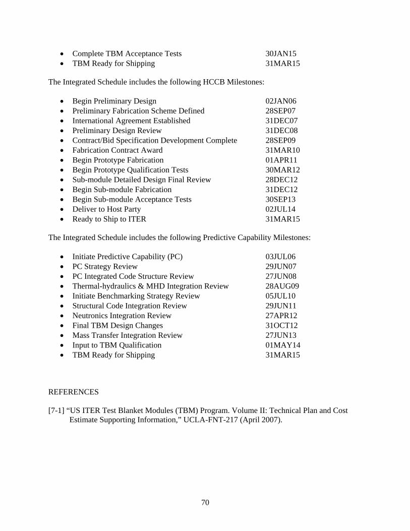
70
• Complete TBM Acceptance Tests 30JAN15 • TBM Ready for Shipping 31MAR15
The Integrated Schedule includes the following HCCB Milestones:
• Begin Preliminary Design 02JAN06 • Preliminary Fabrication Scheme Defined 28SEP07 • International Agreement Established 31DEC07 • Preliminary Design Review 31DEC08 • Contract/Bid Specification Development Complete 28SEP09 • Fabrication Contract Award 31MAR10 • Begin Prototype Fabrication 01APR11 • Begin Prototype Qualification Tests 30MAR12 • Sub-module Detailed Design Final Review 28DEC12 • Begin Sub-module Fabrication 31DEC12 • Begin Sub-module Acceptance Tests 30SEP13 • Deliver to Host Party 02JUL14 • Ready to Ship to ITER 31MAR15
The Integrated Schedule includes the following Predictive Capability Milestones:
• Initiate Predictive Capability (PC) 03JUL06 • PC Strategy Review 29JUN07 • PC Integrated Code Structure Review 27JUN08 • Thermal-hydraulics & MHD Integration Review 28AUG09 • Initiate Benchmarking Strategy Review 05JUL10 • Structural Code Integration Review 29JUN11 • Neutronics Integration Review 27APR12 • Final TBM Design Changes 31OCT12 • Mass Transfer Integration Review 27JUN13 • Input to TBM Qualification 01MAY14 • TBM Ready for Shipping 31MAR15
REFERENCES [7-1] “US ITER Test Blanket Modules (TBM) Program. Volume II: Technical Plan and Cost
Estimate Supporting Information,” UCLA-FNT-217 (April 2007).

UCLA-FNT-216
71
Figure 7-1: US TBM Integrated Schedule (IPS) – Major Tasks and Milestones
WBS ActivityID
ActivityDescription
riueu% Early
StartEarly
FinishBudgetedCost ('06)
Costs w/Escalation
1.8 Test Blanket1.8.1 DCLL System and Testing Goals1.8.1 8112101 Preliminary Design Initiated 31MAY06 0 01.8.1 8112102 Preliminary Design Midpoint Review 02JUL07* 0 01.8.1 8112103 Preliminary Design Review 30JUN08 0 01.8.1 8112113 Select Fabrication Route 31DEC08 0 01.8.1 8112104 Fabrication Bid Package Initiation 28AUG09 0 01.8.1 8112105 Detailed Design Final Design Review 01SEP10 0 01.8.1 811415 DCLL Fabrication Contract Awards 02SEP10 0 01.8.1 8112106 Title III Design Review - Initiate Prototype Fab 30JUN11 0 01.8.1 8112108 Complete Prototype Fabrication 30APR12 0 01.8.1 8112107 Final TBM Design Changes 31DEC12 0 01.8.1 8112109 Initiate TBM Fabrication 28JUN13 0 01.8.1 8112110 Complete TBM Fabrication 30APR14 0 01.8.1 8112111 Complete TBM Acceptance Tests 30JAN15 0 01.8.1 8112112 TBM Ready for Shipping 31MAR15 0 0
1.8.1.1 Test Module1.8.1.1 81110050 Begin DCLL Test Module 02JAN06* 0 0
+ 1.8.1.1.1 Administration02JAN06 20MAR15 2,500,000 2,852,082
+ 1.8.1.1.2 R&D02JAN06 28JAN15 34,427,477 37,968,430
+ 1.8.1.1.3 Engineering02JAN06 30JAN15 10,563,827 11,600,749
+ 1.8.1.1.4 Prototype TBM Design & Fabrication03SEP09 30APR12 1,540,238 1,806,588
+ 1.8.1.1.5 Prototype Assembly, Testing & Installation01MAY12 31MAY13 203,385 242,028
+ 1.8.1.1.6 TBM Fabrication02SEP10 31MAR15 1,340,028 1,594,492
+ 1.8.1.1.7 Acceptance Tests & Packaging01MAY14 31MAR15 89,400 106,386
1.8.1.2 Helium Flow Loops+ 1.8.1.2.1 Primary Helium Loop
02JAN06 31DEC14 2,106,465 2,453,862
+ 1.8.1.2.2 Intermediate Helium Loop02JAN06 31DEC14 1,914,465 2,225,382
FY06 FY07 FY08 FY09 FY10 FY11 FY12 FY13 FY14 FY15
Preliminary Design Initiated
Preliminary Design Midpoint Review
Preliminary Design Review
Select Fabrication Route
Fabrication Bid Package Initiation
Detailed Design Final Design Review
DCLL Fabrication Contract Awards
Title III Design Review - Initiate Prototype Fab
Complete Prototype Fabrication
Final TBM Design Changes
Initiate TBM Fabrication
Complete TBM Fabrication
Complete TBM Acceptance Tests
TBM Ready for Shipping
Begin DCLL Test Module
© Primavera Systems, Inc.
Start Date 02JAN06Finish Date 31MAR15Data Date 02JAN06Run Date 29JUN06 11:05
Early Bar
Progress Bar
Critical Activity
TBM9
ITER TBM ProjectJune 28 2006 Project Summary Schedule
Sheet 1 of 5Date Revision Checked Approved

72
WBS ActivityID
ActivityDescription
riueu% Early
StartEarly
FinishBudgetedCost ('06)
Costs w/Escalation
1.8.1.3 PbLi Flow Loop+ 1.8.1.3.1 Preliminary Design of PbLi Loop
02JAN06 31DEC08 149,555 155,130
+ 1.8.1.3.2 Detailed Design of PbLi Loop01JAN09 31MAR11 663,550 747,610
+ 1.8.1.3.3 Fabrication / Procurement01APR11 28JUN13 2,569,595 3,057,818
+ 1.8.1.3.4 Assembly, Testing & Installation01JUL13 31DEC14 107,155 127,515
1.8.1.4 Tritium Processing Systems+ 1.8.1.4.1 Administration
01FEB06 30JUN14 116,000 131,381
+ 1.8.1.4.2 R&D03OCT07 31DEC12 1,455,000 1,648,599
+ 1.8.1.4.3 Engineering01OCT13 20MAR15 0 0
1.8.1.5 DCLL / ITER System Integration+ 1.8.1.5.1 Administration1.8.1.5.1 03JUL06 26DEC14 0 0
+ 1.8.1.5.2 R&D01JAN08 30SEP09 321,040 346,693
+ 1.8.1.5.3 TBM System Design Integration03JUL06 16JAN13 1,336,654 1,526,922
+ 1.8.1.5.4 Fabrication, Procurement & Shipping.03JAN12 29JAN14 125,000 148,750
+ 1.8.1.5.5 Assembly & On-Site Testing31JAN13 02JAN15 231,000 274,890
1.8.2 HCCB1.8.2 8213100 Begin Preliminary Design 02JAN06* 0 01.8.2 82130135 Preliminary Fabrication Scheme Defined 28SEP07 0 01.8.2 82130155 International Agreement Established 31DEC07 0 01.8.2 82130200 Prelim Design Review 31DEC08 0 01.8.2 82130245 Contract/Bid Specification Development 28SEP09 0 01.8.2 82140110 Fabrication Contract Award 31MAR10 0 01.8.2 82140400 Begin Prototype Fabrication 01APR11 0 01.8.2 82140500 Begin Prototype Qualification Tests 30MAR12 0 01.8.2 82140700 Begin Submodule Fabrication 31DEC12 0 01.8.2 82130310 Submodule Detailed Design Final Review 28DEC12 0 01.8.2 82140800 Begin Submodule Acceptance Tests 30SEP13 0 0
FY06 FY07 FY08 FY09 FY10 FY11 FY12 FY13 FY14 FY15
Begin Preliminary Design
Preliminary Fabrication Scheme Defined
International Agreement Established
Prelim Design Review
Contract/Bid Specification Development Complete
Fabrication Contract Award
Begin Prototype Fabrication
Begin Prototype Qualification Tests
Begin Submodule Fabrication
Submodule Detailed Design Final Review
Begin Submodule Acceptance Tests
© Primavera Systems, Inc.
Start Date 02JAN06Finish Date 31MAR15Data Date 02JAN06Run Date 29JUN06 11:05
Early Bar
Progress Bar
Critical Activity
TBM9
ITER TBM ProjectJune 28 2006 Project Summary Schedule
Sheet 2 of 5Date Revision Checked Approved

UCLA-FNT-216
73
WBS ActivityID
ActivityDescription
riueu% Early
StartEarly
FinishBudgetedCost ('06)
Costs w/Escalation
1.8.2 82150110 Deliver to Host Party 02JUL14 0 01.8.2 82150210 Ready to Ship to ITER 31MAR15 0 0
1.8.2.1 Test Submodule+ 1.8.2.1.1 Administration
02JAN06 20MAR15 1,684,000 1,920,543
+ 1.8.2.1.2 R&D02JAN06 20MAR15 7,376,705 8,234,110
+ 1.8.2.1.3 Engineering02JAN06 31MAR14 3,900,118 4,405,349
+ 1.8.2.1.4 Prototype & TBM Fabrication & Testing29SEP09 01APR14 1,384,460 1,626,093
+ 1.8.2.1.5 TBM Integration & Shipping to ITER02APR14 31MAR15 311,000 370,090
1.8.2.2 Ancillary Equipment+ 1.8.2.2.1 Administration
02APR09 20MAR15 49,960 59,193
+ 1.8.2.2.2 Engineering01JAN09 31MAR14 49,904 58,103
+ 1.8.2.2.3 Fabrication/Procurement03JAN11 31MAR14 130,056 154,767
+ 1.8.2.2.4 Assembly/Installation01APR14 31MAR15 83,000 98,770
+ 1.8.2.2.5 US Contribution to Port A He cooling system29SEP08 26SEP13 800,000 937,510
1.8.2.3 HCCB / ITER System Integration+ 1.8.2.3.1 Liason w/ IT/Parties on Machine/System Interface
01OCT07 20MAR15 593,100 693,409
+ 1.8.2.3.2 Documentation01OCT07 20MAR15 44,700 52,260
+ 1.8.2.3.3 Port Cell Layout & Sys/Piping Integration01JUL11 20MAR15 500,120 595,143
+ 1.8.2.3.4 Data Acquisition, Instrumentation & Ctrl Integra29MAR13 20MAR15 156,860 186,663
1.8.3 Predictive Capabilities1.8.3 1831000 Initiate Predictive Capability (PC) 03JUL06* 0 01.8.3 1831101 PC Strategy Review 29JUN07 0 01.8.3 1831102 PC Integrated Code Structure Review 27JUN08 0 01.8.3 1831103 Thermalhydraulics & MHD Integration Review 28AUG09 0 01.8.3 1831104 Initiate Benchmarking Strategy Review 05JUL10 0 0
FY06 FY07 FY08 FY09 FY10 FY11 FY12 FY13 FY14 FY15Deliver to Host Party
Ready to Ship to ITER
Initiate Predictive Capability (PC)
PC Strategy Review
PC Integrated Code Structure Review
Thermalhydraulics & MHD Integration Review
Initiate Benchmarking Strategy Review
© Primavera Systems, Inc.
Start Date 02JAN06Finish Date 31MAR15Data Date 02JAN06Run Date 29JUN06 11:05
Early Bar
Progress Bar
Critical Activity
TBM9
ITER TBM ProjectJune 28 2006 Project Summary Schedule
Sheet 3 of 5Date Revision Checked Approved

74
WBS ActivityID
ActivityDescription
rueu% Early
StartEarly
FinishBudgetedCost ('06)
Costs w/Escalation
1.8.3 1831105 Structural Code Integration Review 29JUN11 0 01.8.3 1831106 Neutronics Integration Review 27APR12 0 01.8.3 1831107 Final TBM Design Changes 31OCT12 0 01.8.3 1831108 Mass Transfer Integration Review 27JUN13 0 01.8.3 1831109 Input to TBM Qualification 01MAY14 0 01.8.3 1831111 TBM Ready for Shipping 31MAR15 0 0
1.8.3.1 Models & Codes+ 1.8.3.1.1 MHD Thermofluid
01MAR06 01SEP10 0 0
+ 1.8.3.1.2 Solid Breeder Thermomechanics1.8.3.1.2 02JAN06 31DEC10 0 0
+ 1.8.3.1.3 Tritium Permeation02OCT06 30DEC11 0 0
+ 1.8.3.1.4 CAD02JAN06 28DEC12 0 0
+ 1.8.3.1.5 Neutronics02JAN06 28DEC12 0 0
+ 1.8.3.1.6 Structural / Stress02JAN06 28DEC12 0 0
+ 1.8.3.1.7 Thermalhydraulics02JAN06 28DEC12 0 0
1.8.3.2 Data, Databases & Constitutive Relations+ 1.8.3.2.1 RAFS Property Data
02OCT06 30DEC10 0 0
+ 1.8.3.2.2 SiC FCI property data02OCT06 29MAR13 0 0
+ 1.8.3.2.3 Solubility data in PbLi02JUL07 30JUN10 0 0
+ 1.8.3.2.4 He Thermalhydraulics1.8.3.2.4 01JUL08 21JUN10 0 0
+ 1.8.3.2.5 Be/FS joint data01MAR07 30JUN09 0 0
+ 1.8.3.2.6 Tritium Permeation Data02OCT06 31OCT11 0 0
+ 1.8.3.2.7 Pebble Bed Thermomechanical Data02JAN06 31DEC10 0 0
1.8.3.3 Data / Codes Integration+ 1.8.3.3.1 Integrated Strategy Development
03JUL06 29JUN07 250,600 256,239
FY06 FY07 FY08 FY09 FY10 FY11 FY12 FY13 FY14 FY15Structural Code Integration Review
Neutronics Integration Review
Final TBM Design Changes
Mass Transfer Integration Review
Input to TBM Qualification
TBM Ready for Shipping
© Primavera Systems, Inc.
Start Date 02JAN06Finish Date 31MAR15Data Date 02JAN06Run Date 29JUN06 11:05
Early Bar
Progress Bar
Critical Activity
TBM9
ITER TBM ProjectJune 28 2006 Project Summary Schedule
Sheet 4 of 5Date Revision Checked Approved

UCLA-FNT-216
75
WBS ActivityID
ActivityDescription
riueu% Early
StartEarly
FinishBudgetedCost ('06)
Costs w/Escalation
+ 1.8.3.3.2 Executive Routines and Data Structure02JUL07 27JUN08 891,000 937,778
+ 1.8.3.3.3 Integration of Simulation Capabilities30JUN08 03MAR15 1,065,450 1,237,017
+ 1.8.3.3.4 Integrated Code Benchmarking & Application05JUL10 31MAR15 704,800 836,524
1.8.4 Project Support1.8.4 1841100 US TBM External Review 16AUG06* 0 01.8.4 1841110 CD0 - Approve Mission Need 02OCT06* 0 01.8.4 1841120 CD1 - Approve Alt Selection & Cost Range 01MAR07* 0 01.8.4 1841130 CD2A - Approve Long Lead Procurement Budget 03DEC07* 0 01.8.4 1841140 CD2B - Approve Performance Baseline 03DEC07* 0 01.8.4 1841150 CD3A - Approve Start of Long Lead 01JUL08* 0 01.8.4 1841160 CD3B - Approve Start of Construction 01OCT08* 0 01.8.4 1841170 CD4 - Approve Start of Operations/ Proj Closeout 01APR15* 0 0
1.8.4.1 Administration1.8.4.1 1841190 TBM Project Management 02JAN06* 20MAR15 2,000,000 2,281,286
1.8.4.2 TBWG / Parties Interface1.8.4.2 1842200 TBWG / Parties Interface 02JAN06* 20MAR15 2,300,000 2,623,764
1.8.4.3 Safety & Regulatory Support1.8.4.3 1843110 Provide Final TBM Safety Input to ITER PSR 01JAN07* 0 01.8.4.3 1843120 Provide TBM Safety Input to ITER FSR 01JAN13* 0 01.8.4.3 1843125 Complete Safety & Regulatory Support 31DEC13 0 0
+ 1.8.4.3.1 Regulatory Support02JAN06 31DEC13 840,000 942,402
+ 1.8.4.3.2 Safety Analysis & Reporting01JUN06 31DEC13 2,260,000 2,554,663
+ 1.8.4.3.3 Safety Design Integration02JAN06 28JUN13 1,385,000 1,543,129
1.8.4.4 Quality Assurance Officer1.8.4.4 1844100 Quality Assurance Officer 02OCT06* 20MAR15 1,227,850 1,395,904
FY06 FY07 FY08 FY09 FY10 FY11 FY12 FY13 FY14 FY15
US TBM External Review
CD0 - Approve Mission Need
CD1 - Approve Alt Selection & Cost Range
CD2A - Approve Long Lead Procurement Budget
CD2B - Approve Performance Baselin
CD3A - Approve Start of Long Lead Procurements
CD3B - Approve Start of Construction
CD4 - Approve Start of Operations/ Proj Closeout
TBM P
TBWG
Provide Final TBM Safety Input to ITER PSR
Provide TBM Safety Input to ITER FSR
Complete Safety & Regulatory Support
Quality
© Primavera Systems, Inc.
Start Date 02JAN06Finish Date 31MAR15Data Date 02JAN06Run Date 29JUN06 11:05
Early Bar
Progress Bar
Critical Activity
TBM9
ITER TBM ProjectJune 28 2006 Project Summary Schedule
Sheet 5 of 5Date Revision Checked Approved

76
This page intentionally left blank

UCLA-FNT-216
77
8. ESCALATION AND CONTINGENCY 8.1 ESCALATION A three percent (3%) escalation rate per year was assumed for this initial cost estimate. The escalation was calculated using the PRIMAVERA professional scheduling software package. This escalation is reflected in Table 6-2. 8.2 CONTINGENCY A critical decision in the US TBM Cost Estimate preparation is the application of a proper contingency. The decision has been made not to apply contingency to the $48.8 M of R&D tasks in this TBM program. This is different than the approach taken initially by the US ITER Program. There are several reasons that this approach has been taken. The US ITER TBM is fundamentally different than the ITER Program or machine in that the ITER basic machine is an assembly of subsystems and components from ITER parties, all of which must work if the program is to be successful. The US ITER TBM Program is for fundamental research that will be conducted on the ITER machine. Much of the R&D is concerned with meeting the experimental mission of the TBMs. As long as the US TBM assemblies do not fail structurally or cause other environmental, health and safety problems, they could be judged from an ITER standpoint to be successful. Moreover, the DOE, under its project management directives and orders, does not normally allow contingency to be applied to this type of research. Beyond this basic philosophy, a review of the details in the cost estimate sheets for the US TBM research shows conservative estimates made by experienced scientists. In a very real sense, applying contingency to the R&D would constitute “double counting.” A contingency has been added to all other TBM activities, including administration, QA, design, material procurements, fabrication, vendor contracts, installation for testing, testing, integration and preparation for shipment. In general, this contingency is 25%, with a low of 10% on Administration and a high of 30% on Ancillary Equipment. The highest contingency applied to any task, activity or specific component is 50%, applied to the TBM Prototypes. Due to the above considerations concerning the R&D, the US TBM overall contingency of 13% is viewed as adequate by the US TBM Team. If total contingency percentage is calculated on just the non-R&D items, it is approximately 24%. Details of this contingency are shown in Chapter 6 in Table 6-3.

78
This page intentionally left blank

UCLA-FNT-216
79
9. RISK ASSESSMENT Risks are summarized here according to the following general categories:
• Technical Risk that H-H phase deliverables do not qualify and so are not accepted for deployment in ITER
• Technical Risk that H-H phase deliverables will fail during operation, jeopardizing ITER operation or availability and subsequent TBM deployment
• Technical Risk that H-H phase deliverables will not meet their operational goals, and so jeopardize their experimental mission and subsequent TBM deployments
• Schedule Risk that H-H phase deliverables are not ready on time • Cost Risk that H-H phase deliverables exceed budget obligation
Since specific ITER qualification and acceptance tests have not yet been fully specified (see Section 3.3), TBM technical designs must be evaluated first to minimize risks that could threaten the compatibility of the H-H phase TBMs with tokamak operations. It is probable that the US will have to present a portfolio of test results and analyses, making a clear case for qualification, prior to receiving ITER approval to install the US TBMs and systems. This establishes the structural integrity, interaction with normal tokamak magnetic operation; including startup and shutdown, and the ability to withstand transient events like ELMs and disruptions as the highest priorities for evaluation in the TBM technical risk assessment for the H-H phase deliverables. R&D activities, laboratory and sub-module tests, prototype and integrated mockup tests, and analysis by verified predictive capabilities have been specifically formulated to address the above risks for the H-H phase and the subsequent D-D and D-T phases. 9.1 DCLL RISK HIGHLIGHTS The primary technical, schedule, and cost risks associated with the DCLL H-H phase TBM plan are mostly associated with the development of the required RAFS fabrication technology that can produce a TBM within US design specifications, that will pass all qualification testing and safety requirements, and that meets schedule deadlines for deployment in the ITER H-H phase. Ancillary loop systems are based to a large degree on available commercial technology and there appears to be sufficient time in the schedule for their design, development, and fabrication. However, there will be limited integrated tests prior to operation in ITER, increasing the likelihood of failures in the ancillary systems during H-H phase TBM operation. Many secondary risks, including SiC FCI development and robustness, and uncertainty in the PbLi MHD predictive capability and experimental database, could potentially lead to failure to meet H-H phase experimental mission and design goals, which in turn may jeopardize subsequent D-D and D-T phase TBM deployment and performance. Additionally, there is also a cost risk associated with the inclusion of costs savings in the DCLL TBM plan associated with “known international collaborations” on fabrication technology, diagnostics, Be armor attachment, etc. The estimated value of these cost savings is $9.4 M of the total (escalated) program cost when compared to an independent DCLL effort (without the

80
benefits of international collaboration). If these “known international collaborations” are not cultivated, the DCLL baseline and high range costs will be increased. The most significant schedule risk in the DCLL TBM plan is the completion of prototype testing in 2012, followed by the incorporation of those test results into the DCLL Final Detailed Design by the end of that year. Prototype testing is viewed as essential to help mitigate fabrication risks (see below), but in order to include time for sufficient prior R&D and design, the prototype fabrication does not begin until September 2010, putting considerable pressure on the first article fabrication schedule. The strategy for dealing with these assorted risks include: (a) beginning RAFS fabrication, SiC fabrication, and thermofluid MHD R&D early, supported by detailed analyses in the corresponding design activity, and (b) the inclusion of a prototype and other partially integrated mockup experiments in order to test the fabrication specifications and operating conditions against ITER qualification requirements in time to influence the final design and DCLL H-H phase TBM fabrication. In addition, (c) firm, clear, national and international commitments, agreements and close communication between partner Parties are required to mitigate collaboration risks as much as possible. The technical details of this agreement must be worked out in early 2007 with both technical and programmatic negotiations, but committing to the formal collaborations is in the DOE’s sphere of responsibility. 9.2 HCCB RISK HIGHLIGHTS Similarly to the DCLL H-H phase TBM plan, the primary risk for the HCCB H-H phase TBM plan is the development of the required RAFS fabrication technology R&D and subsequent fabrication sequence that can produce a sub-module within US design specifications, pass all qualification requirements, and meet schedule deadlines for deployment. It should also be noted that the ceramic breeder material in the H-H sub-module does not provide any function during the tests, and that there is a technical risk in the current R&D plan concerning database adequacy for defining and procuring the best ceramic breeder materials (including microstructures and Li enrichment) for the subsequent HCCB D-D and D-T phase sub-modules. This technical risk is primarily derived from the decision to monitor and evaluate the existing international R&D on ceramic breeder material fabrication rather than developing a ceramic breeder material in the US. Additionally, there are schedule and cost risks in the HCCB strategy associated with relying upon an international partner for large portions of the R&D, ancillary equipment, and TBM support structure for the US HCCB sub-module. The mitigation actions included in the HCCB plan include early funding of critical joint R&D maintaining US expertise, and most importantly, an early official agreement with an international partner (a milestone for which appears in December 2007), close monitoring of international partner progress and problems, and close coupling the DCLL R&D activities affecting HCCB milestones. The technical details of this agreement must be worked out beginning in early 2007 with both technical and programmatic negotiations, but committing to the formal collaborations is in the DOE’s sphere of responsibility.
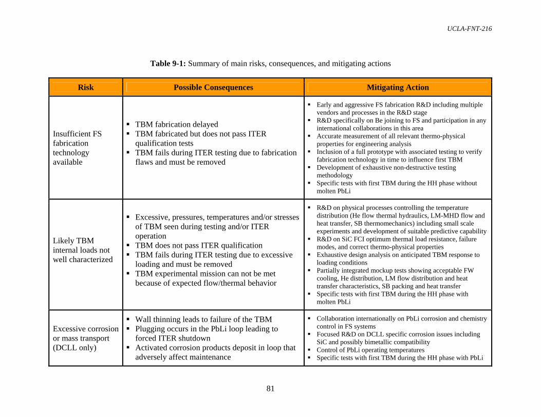
UCLA-FNT-216
81
Table 9-1: Summary of main risks, consequences, and mitigating actions
Risk Possible Consequences Mitigating Action
Insufficient FS fabrication technology available
TBM fabrication delayed TBM fabricated but does not pass ITER
qualification tests TBM fails during ITER testing due to fabrication
flaws and must be removed
Early and aggressive FS fabrication R&D including multiple vendors and processes in the R&D stage
R&D specifically on Be joining to FS and participation in any international collaborations in this area
Accurate measurement of all relevant thermo-physical properties for engineering analysis
Inclusion of a full prototype with associated testing to verify fabrication technology in time to influence first TBM
Development of exhaustive non-destructive testing methodology
Specific tests with first TBM during the HH phase without molten PbLi
Likely TBM internal loads not well characterized
Excessive, pressures, temperatures and/or stresses of TBM seen during testing and/or ITER operation
TBM does not pass ITER qualification TBM fails during ITER testing due to excessive
loading and must be removed TBM experimental mission can not be met
because of expected flow/thermal behavior
R&D on physical processes controlling the temperature distribution (He flow thermal hydraulics, LM-MHD flow and heat transfer, SB thermomechanics) including small scale experiments and development of suitable predictive capability
R&D on SiC FCI optimum thermal load resistance, failure modes, and correct thermo-physical properties
Exhaustive design analysis on anticipated TBM response to loading conditions
Partially integrated mockup tests showing acceptable FW cooling, He distribution, LM flow distribution and heat transfer characteristics, SB packing and heat transfer
Specific tests with first TBM during the HH phase with molten PbLi
Excessive corrosion or mass transport (DCLL only)
Wall thinning leads to failure of the TBM Plugging occurs in the PbLi loop leading to
forced ITER shutdown Activated corrosion products deposit in loop that
adversely affect maintenance
Collaboration internationally on PbLi corrosion and chemistry control in FS systems
Focused R&D on DCLL specific corrosion issues including SiC and possibly bimetallic compatibility
Control of PbLi operating temperatures Specific tests with first TBM during the HH phase with PbLi

82
Water comes in contact with PbLi or Be during accident
Excessive H2 generation during PbLi or Be contact with water lead to explosion hazard, TBM system does not pass ITER qualification
Collaboration internationally on establishing case for PbLi volume up to 600l
Perform early, focused R&D on obtain data and code simulations that establish this case, or show that lower PbLi volume must be used
TBM diagnostics and control systems do not function well
TBM does not pass ITER qualification tests due safety impact of insufficient diagnosis and control
TBM diagnostics fail during ITER testing and and TBM must be removed or experimental mission is negatively impacted
TBM diagnostics fail during ITER testing and experimental mission is negatively impacted
Collaboration internationally on diagnostic development for nuclear and non-nuclear TBMs
Focused R&D on DCLL specific diagnostic development issues
Test diagnostics on partially-integrated mockup tests Specific tests with first TBM during the HH phase
FS TBMs excessively impact local magnetic field
ITER compensation systems can not successfully compensate for FS disturbance and TBM must be removed
Static forces lead to TBM failure and TBM must be removed
Simulations of magnetic disturbances and forces due to presence of TBMs using ITER accepted simulation codes
Specific tests with first TBM during HH phase without and later with molten PbLi
Collaboration partners do not meet their obligations
Fabrication of TBM is delayed and US costs increase due to need for US to perform additional R&D, analysis or fabrication tasks
TBM does not qualify due to insufficient R&D or analysis database
Consider independent US program on DCLL with smaller dependence on international partners for most critical R&D, design and analysis
Early official agreements with, and close monitoring of, collaboration partners
Disruptions loads not well known and more severe than anticipated
TBM structure is breached releasing He, PbLi, SB, Be or all into the vacuum vessel requiring TBM replacement and extensive ITER cleanup
FCIs damaged leading to highly unbalanced PbLi flow requiring ITER shutdown and TBM replacement (DCLL only)
Validate structure during HH phase tests first without molten PbLi
Perform impact tests on SiC samples to assess resistance to pulsed loads
Investigate FCI performance with PbLi in the HH phase

83
10. FUNDING PROFILE As noted above, the cost and scheduling produced for this conceptual US TBM program planning activity was produced using the PRIMAVERA professional scheduling software. This tool can automatically produce from the resource loaded Integrated Schedule the required funding profiles by year required to complete the program. Figure 10-1 shows an approximate cost and contingency profile for the Baseline US TBM Program. It should be noted that the FY06 funding has been constrained to reflect, as much as possible, the reality of available funding during this fiscal year. The ~$3 M is not the full funding that would have been necessary if an optimum plan was being executed, and this places a strain on the years immediately following FY06, where budget ramp-up is steep. A peak funding of roughly $20 M is required in years FY09 and FY10. Note also that some resources have been distributed among FY09, FY10, and FY11 to produce a flatter profile. This redistribution has not yet been fully implemented in the detailed integrated schedule. The FY15 budget is artificially low because of the end of the performance period at the end of March 2015. In reality, the program necessary to install and perform experiments with the first TBM in ITER and the design and fabrication of a 2nd US TBMs will both have to begin at this time.
$0
$5,000
$10,000
$15,000
$20,000
$25,000
Contingency (k$)Escalated Cost (k$)
Contingency (k$) $414 $1,446 $1,781 $2,321 $2,572 $2,198 $1,424 $757 $429 $83
Escalated Cost (k$) $3,179 $11,097 $13,666 $17,813 $18,433 $15,563 $10,925 $5,812 $3,289 $640
FY06 FY07 FY08 FY09 FY10 FY11 FY12 FY13 FY14 FY15
Figure 10-1: US TBM baseline scenario funding profile by fiscal year through March 2015 (Escalated cost includes both TBM Project and Base Program, in thousands of dollars)

84
This page intentionally left blank
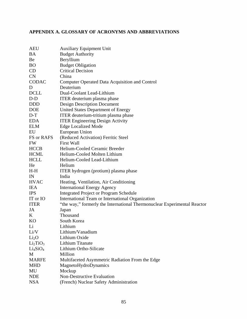
85
APPENDIX A. GLOSSARY OF ACRONYMS AND ABBREVIATIONS AEU Auxiliary Equipment Unit BA Budget Authority Be Beryllium BO Budget Obligation CD Critical Decision CN China CODAC Computer Operated Data Acquisition and Control D Deuterium DCLL Dual-Coolant Lead-Lithium D-D ITER deuterium plasma phase DDD Design Description Document DOE United States Department of Energy D-T ITER deuterium-tritium plasma phase EDA ITER Engineering Design Activity ELM Edge Localized Mode EU European Union FS or RAFS (Reduced Activation) Ferritic Steel FW First Wall HCCB Helium-Cooled Ceramic Breeder HCML Helium-Cooled Molten Lithium HCLL Helium-Cooled Lead-Lithium He Helium H-H ITER hydrogen (protium) plasma phase IN India HVAC Heating, Ventilation, Air Conditioning IEA International Energy Agency IPS Integrated Project or Program Schedule IT or IO International Team or International Organization ITER “the way,” formerly the International Thermonuclear Experimental Reactor JA Japan K Thousand KO South Korea Li Lithium Li/V Lithium/Vanadium Li2O Lithium Oxide Li2TiO3 Lithium Titanate Li4SiO4 Lithium Ortho-Silicate M Million MARFE Multifaceted Asymmetric Radiation From the Edge MHD MagnetoHydroDynamics MU Mockup NDE Non-Destructive Evaluation NSA (French) Nuclear Safety Administration

86
NWL Neutron Wall Load OFES Department of Energy - Office of Fusion Energy Sciences OS Department of Energy - Office of Science Pb Lead PbLi Lead-Lithium alloy PC Predictive Capability PFC Plasma Facing Component PHTS Primary Heat Transfer Systems QA/QC Quality Assurance / Quality Control R&D Research and Development RF Russian Federation RPrS Report on Preliminary Safety SHF Surface Heat Flux T Tritium or Tesla TBM Test Blanket Module TCWS Tokamak Cooling Water System TITAN US-Japan technology and materials collaboration (2007-2013) TPC Total Program Cost TSD Technical Specification Document US United States V Volt or Vanadium VDE Vertical Displacement Event VLT DOE OFES - Virtual Laboratory for Technology WBS Work Breakdown Structure WCCB Water Cooled Ceramic Breeder
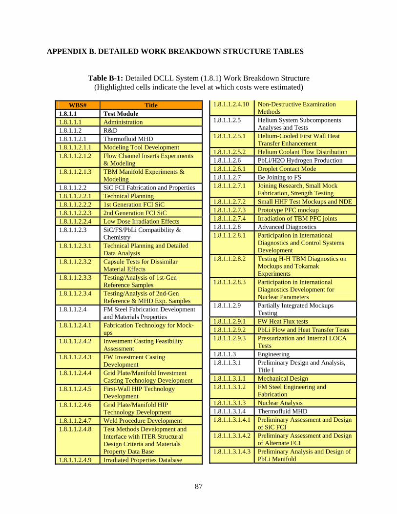
87
APPENDIX B. DETAILED WORK BREAKDOWN STRUCTURE TABLES
Table B-1: Detailed DCLL System (1.8.1) Work Breakdown Structure (Highlighted cells indicate the level at which costs were estimated)
WBS# Title
1.8.1.1 Test Module 1.8.1.1.1 Administration 1.8.1.1.2 R&D 1.8.1.1.2.1 Thermofluid MHD 1.8.1.1.2.1.1 Modeling Tool Development 1.8.1.1.2.1.2 Flow Channel Inserts Experiments
& Modeling 1.8.1.1.2.1.3 TBM Manifold Experiments &
Modeling 1.8.1.1.2.2 SiC FCI Fabrication and Properties 1.8.1.1.2.2.1 Technical Planning 1.8.1.1.2.2.2 1st Generation FCI SiC 1.8.1.1.2.2.3 2nd Generation FCI SiC 1.8.1.1.2.2.4 Low Dose Irradiation Effects 1.8.1.1.2.3 SiC/FS/PbLi Compatibility &
Chemistry 1.8.1.1.2.3.1 Technical Planning and Detailed
Data Analysis 1.8.1.1.2.3.2 Capsule Tests for Dissimilar
Material Effects 1.8.1.1.2.3.3 Testing/Analysis of 1st-Gen
Reference Samples 1.8.1.1.2.3.4 Testing/Analysis of 2nd-Gen
Reference & MHD Exp. Samples 1.8.1.1.2.4 FM Steel Fabrication Development
and Materials Properties 1.8.1.1.2.4.1 Fabrication Technology for Mock-
ups 1.8.1.1.2.4.2 Investment Casting Feasibility
Assessment 1.8.1.1.2.4.3 FW Investment Casting
Development 1.8.1.1.2.4.4 Grid Plate/Manifold Investment
Casting Technology Development 1.8.1.1.2.4.5 First-Wall HIP Technology
Development 1.8.1.1.2.4.6 Grid Plate/Manifold HIP
Technology Development 1.8.1.1.2.4.7 Weld Procedure Development 1.8.1.1.2.4.8 Test Methods Development and
Interface with ITER Structural Design Criteria and Materials Property Data Base
1.8.1.1.2.4.9 Irradiated Properties Database
1.8.1.1.2.4.10 Non-Destructive Examination Methods
1.8.1.1.2.5 Helium System Subcomponents Analyses and Tests
1.8.1.1.2.5.1 Helium-Cooled First Wall Heat Transfer Enhancement
1.8.1.1.2.5.2 Helium Coolant Flow Distribution 1.8.1.1.2.6 PbLi/H2O Hydrogen Production 1.8.1.1.2.6.1 Droplet Contact Mode 1.8.1.1.2.7 Be Joining to FS 1.8.1.1.2.7.1 Joining Research, Small Mock
Fabrication, Strength Testing 1.8.1.1.2.7.2 Small HHF Test Mockups and NDE 1.8.1.1.2.7.3 Prototype PFC mockup 1.8.1.1.2.7.4 Irradiation of TBM PFC joints 1.8.1.1.2.8 Advanced Diagnostics 1.8.1.1.2.8.1 Participation in International
Diagnostics and Control Systems Development
1.8.1.1.2.8.2 Testing H-H TBM Diagnostics on Mockups and Tokamak Experiments
1.8.1.1.2.8.3 Participation in International Diagnostics Development for Nuclear Parameters
1.8.1.1.2.9 Partially Integrated Mockups Testing
1.8.1.1.2.9.1 FW Heat Flux tests 1.8.1.1.2.9.2 PbLi Flow and Heat Transfer Tests 1.8.1.1.2.9.3 Pressurization and Internal LOCA
Tests 1.8.1.1.3 Engineering 1.8.1.1.3.1 Preliminary Design and Analysis,
Title I 1.8.1.1.3.1.1 Mechanical Design 1.8.1.1.3.1.2 FM Steel Engineering and
Fabrication 1.8.1.1.3.1.3 Nuclear Analysis 1.8.1.1.3.1.4 Thermofluid MHD 1.8.1.1.3.1.4.1 Preliminary Assessment and Design
of SiC FCI 1.8.1.1.3.1.4.2 Preliminary Assessment and Design
of Alternate FCI 1.8.1.1.3.1.4.3 Preliminary Analysis and Design of
PbLi Manifold
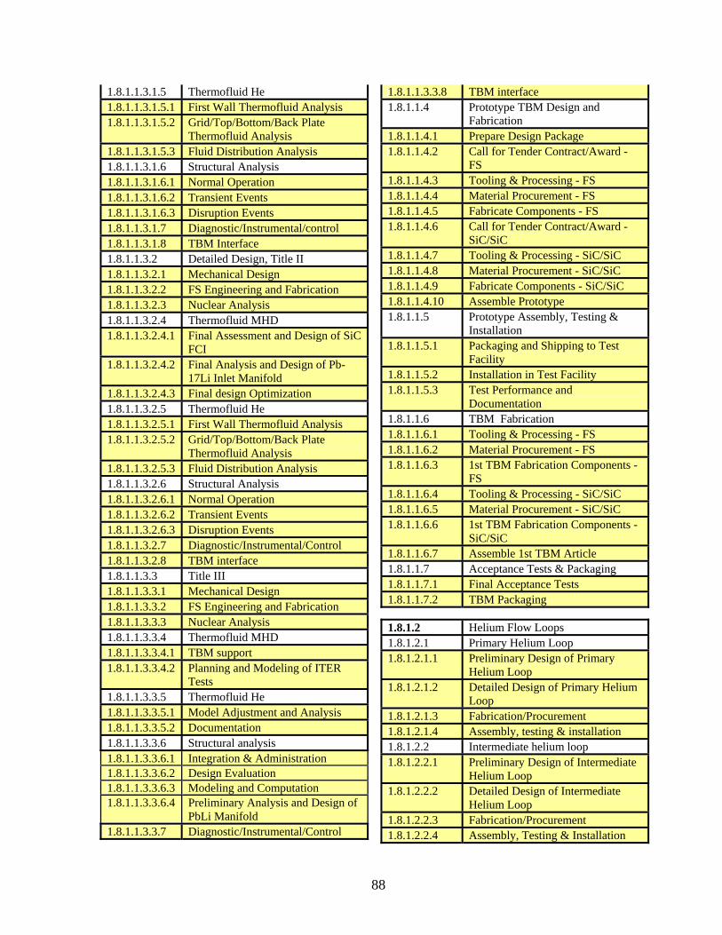
88
1.8.1.1.3.1.5 Thermofluid He 1.8.1.1.3.1.5.1 First Wall Thermofluid Analysis 1.8.1.1.3.1.5.2 Grid/Top/Bottom/Back Plate
Thermofluid Analysis 1.8.1.1.3.1.5.3 Fluid Distribution Analysis 1.8.1.1.3.1.6 Structural Analysis 1.8.1.1.3.1.6.1 Normal Operation 1.8.1.1.3.1.6.2 Transient Events 1.8.1.1.3.1.6.3 Disruption Events 1.8.1.1.3.1.7 Diagnostic/Instrumental/control 1.8.1.1.3.1.8 TBM Interface 1.8.1.1.3.2 Detailed Design, Title II 1.8.1.1.3.2.1 Mechanical Design 1.8.1.1.3.2.2 FS Engineering and Fabrication 1.8.1.1.3.2.3 Nuclear Analysis 1.8.1.1.3.2.4 Thermofluid MHD 1.8.1.1.3.2.4.1 Final Assessment and Design of SiC
FCI 1.8.1.1.3.2.4.2 Final Analysis and Design of Pb-
17Li Inlet Manifold 1.8.1.1.3.2.4.3 Final design Optimization 1.8.1.1.3.2.5 Thermofluid He 1.8.1.1.3.2.5.1 First Wall Thermofluid Analysis 1.8.1.1.3.2.5.2 Grid/Top/Bottom/Back Plate
Thermofluid Analysis 1.8.1.1.3.2.5.3 Fluid Distribution Analysis 1.8.1.1.3.2.6 Structural Analysis 1.8.1.1.3.2.6.1 Normal Operation 1.8.1.1.3.2.6.2 Transient Events 1.8.1.1.3.2.6.3 Disruption Events 1.8.1.1.3.2.7 Diagnostic/Instrumental/Control 1.8.1.1.3.2.8 TBM interface 1.8.1.1.3.3 Title III 1.8.1.1.3.3.1 Mechanical Design 1.8.1.1.3.3.2 FS Engineering and Fabrication 1.8.1.1.3.3.3 Nuclear Analysis 1.8.1.1.3.3.4 Thermofluid MHD 1.8.1.1.3.3.4.1 TBM support 1.8.1.1.3.3.4.2 Planning and Modeling of ITER
Tests 1.8.1.1.3.3.5 Thermofluid He 1.8.1.1.3.3.5.1 Model Adjustment and Analysis 1.8.1.1.3.3.5.2 Documentation 1.8.1.1.3.3.6 Structural analysis 1.8.1.1.3.3.6.1 Integration & Administration 1.8.1.1.3.3.6.2 Design Evaluation 1.8.1.1.3.3.6.3 Modeling and Computation 1.8.1.1.3.3.6.4 Preliminary Analysis and Design of
PbLi Manifold 1.8.1.1.3.3.7 Diagnostic/Instrumental/Control
1.8.1.1.3.3.8 TBM interface 1.8.1.1.4 Prototype TBM Design and
Fabrication 1.8.1.1.4.1 Prepare Design Package 1.8.1.1.4.2 Call for Tender Contract/Award -
FS 1.8.1.1.4.3 Tooling & Processing - FS 1.8.1.1.4.4 Material Procurement - FS 1.8.1.1.4.5 Fabricate Components - FS 1.8.1.1.4.6 Call for Tender Contract/Award -
SiC/SiC 1.8.1.1.4.7 Tooling & Processing - SiC/SiC 1.8.1.1.4.8 Material Procurement - SiC/SiC 1.8.1.1.4.9 Fabricate Components - SiC/SiC 1.8.1.1.4.10 Assemble Prototype 1.8.1.1.5 Prototype Assembly, Testing &
Installation 1.8.1.1.5.1 Packaging and Shipping to Test
Facility 1.8.1.1.5.2 Installation in Test Facility 1.8.1.1.5.3 Test Performance and
Documentation 1.8.1.1.6 TBM Fabrication 1.8.1.1.6.1 Tooling & Processing - FS 1.8.1.1.6.2 Material Procurement - FS 1.8.1.1.6.3 1st TBM Fabrication Components -
FS 1.8.1.1.6.4 Tooling & Processing - SiC/SiC 1.8.1.1.6.5 Material Procurement - SiC/SiC 1.8.1.1.6.6 1st TBM Fabrication Components -
SiC/SiC 1.8.1.1.6.7 Assemble 1st TBM Article 1.8.1.1.7 Acceptance Tests & Packaging 1.8.1.1.7.1 Final Acceptance Tests 1.8.1.1.7.2 TBM Packaging
1.8.1.2 Helium Flow Loops 1.8.1.2.1 Primary Helium Loop 1.8.1.2.1.1 Preliminary Design of Primary
Helium Loop 1.8.1.2.1.2 Detailed Design of Primary Helium
Loop 1.8.1.2.1.3 Fabrication/Procurement 1.8.1.2.1.4 Assembly, testing & installation 1.8.1.2.2 Intermediate helium loop 1.8.1.2.2.1 Preliminary Design of Intermediate
Helium Loop 1.8.1.2.2.2 Detailed Design of Intermediate
Helium Loop 1.8.1.2.2.3 Fabrication/Procurement 1.8.1.2.2.4 Assembly, Testing & Installation

89
1.8.1.3 PbLi Flow Loop 1.8.1.3.1 Preliminary Design of the PbLi loop 1.8.1.3.2 Detailed Design of the PbLi loop 1.8.1.3.3 Fabrication/Procurement 1.8.1.3.4 Assembly, Testing & Installation
1.8.1.4 Tritium Processing 1.8.1.4.1 Administration 1.8.1.4.2 R&D 1.8.1.4.2.1 Modeling 1.8.1.4.2.2 Fate of Tritium in PbLi 1.8.1.4.2.3 Tritium Extraction from PbLi 1.8.1.4.2.4 Tritium Extraction from He
1.8.1.4.3 Engineering
1.8.1.4.3.1 Design
1.8.1.4.3.1.1 Tritium Extraction from PbLi 1.8.1.4.3.1.2 Tritium Extraction from He 1.8.1.4.3.1.3 System Integration 1.8.1.4.3.2 Title III 1.8.1.4.4 Fabrication/Procurement 1.8.1.4.5 Assembly/Installation
1.8.1.5 DCLL/ITER System Integration 1.8.1.5.1 Administration 1.8.1.5.2 R&D 1.8.1.5.2.1 He and PbLi Concentric Pipe Joints 1.8.1.5.2.2 VV Plug Bellows Design 1.8.1.5.3 TBM System Design Integration 1.8.1.5.3.1 In-Vessel System Integration

90
Table B-2: Detailed HCCB System (1.8.2) Work Breakdown Structure (Highlighted cells indicate the level at which costs were estimated)
WBS# Title 1.8.2.1 Test Sub-module 1.8.2.1.1 Administration 1.8.2.1.2 R&D 1.8.2.1.2.1 Helium flow distribution and
manifold flow testing 1.8.2.1.2.2 Solid breeder thermomechanics &
temperature window for T release 1.8.2.1.2.3 RAFS Fabrication development 1.8.2.1.2.4 Tritium control and predictive
capability 1.8.2.1.2.5 Breeder Pebble Knowledge Base &
Proc Spec 1.8.2.1.2.6 Diagnostics and Instrumentation 1.8.2.1.2.7 Partially Integrated Tests 1.8.2.1.2.7.1 Helium Flow & Heat Transfer Tests 1.8.2.1.2.7.2 Prototype Pressurization Testing 1.8.2.1.2.8 In-Pile Pebble Bed Assembly Test 1.8.2.1.2.8.1 In-pile Thermo-mechanical and
Breeder Evaluation 1.8.2.1.2.8.2 In-situ PBA Performance Evaluation 1.8.2.1.3 Engineering 1.8.2.1.3.1 Preliminary Design 1.8.2.1.3.2 Detailed Design 1.8.2.1.3.3 Title III 1.8.2.1.4 Prototype & TBM Fabrication &
Testing 1.8.2.1.4.1 Call for tender/Contract award 1.8.2.1.4.2 Material Procurement 1.8.2.1.4.3 Tooling & Processing 1.8.2.1.4.4 Prototype fabrication 1.8.2.1.4.5 Prototype qualification tests
1.8.2.1.4.6 TBM sub-module material procurement
1.8.2.1.4.7 TBM sub-module fabrication 1.8.2.1.4.8 TBM sub-module acceptance tests 1.8.2.1.5 TBM Integration & Shipping to
ITER 1.8.2.1.5.1 Party integration & Module
Acceptance Tests 1.8.2.1.5.2 Packaging
1.8.2.2 Ancillary Equipment 1.8.2.2.1 Administration 1.8.2.2.2 Engineering 1.8.2.2.2.1 Preliminary design, Title I 1.8.2.2.2.2 Detailed Design 1.8.2.2.2.3 Title III 1.8.2.2.3 Fabrication / Procurement 1.8.2.2.4 Assembly / Installation 1.8.2.2.5 US Contribution to Port A Helium
Loop 1.8.2.3 HCCB/ITER System Integration 1.8.2.3.1 Liaison with IT/Parties 1.8.2.3.2 Documentation 1.8.2.3.3 Port cell layout & sys/piping 1.8.2.3.4 Data acquisition, instrument and
control integration

91
Table B-3: Detailed Predictive Capability (1.8.3) Work Breakdown Structure (Costs for 1.8.3.1 and 1.8.3.2 were collected under 1.8.1 and 1.8.2 as needed for design and
analysis efforts, Highlighted cells in 1.8.3.3 indicate the level at which costs were estimated)
WBS# Title 1.8.3.1 Models and Codes 1.8.3.1.1 MHD Thermofluid 1.8.3.1.2 Solid breeder thermomechanics 1.8.3.1.3 Tritium Permeation 1.8.3.1.4 CAD 1.8.3.1.5 Neutronics 1.8.3.1.6 Structural/Stress 1.8.3.1.7 Thermal-hydraulics 1.8.3.2 Data, Databases, & Constitutive
Relations 1.8.3.2.1 RAFS property data 1.8.3.2.2 SiC FCI property data 1.8.3.2.3 Solubility data in PbLi 1.8.3.2.4 He thermal-hydraulics 1.8.3.2.5 Be/FS joint data 1.8.3.2.6 Tritium permeation data 1.8.3.2.7 Pebble bed thermomechanical data 1.8.3.3 Data/Codes Integration 1.8.3.3.1 Integrated Strategy Development 1.8.3.3.2 Executive Routines and Data Structure 1.8.3.3.3 Integration of Simulation Capabilities and
Associated Data 1.8.3.3.4 Integrated Code Benchmarking and
Application
Table B-4: Detailed Project Support (1.8.4) Work Breakdown Structure (Highlighted cells indicate the level at which costs were estimated)
WBS# Title 1.8.4.1 Administration 1.8.4.2 TBWG/Parties Interface 1.8.4.3 Safety and Regulatory Support 1.8.4.3.1 Regulatory Support 1.8.4.3.2 Safety Analysis and Reporting 1.8.4.3.3 Safety Design Integration 1.8.4.4 Quality Assurance Officer

92
This page intentionally left blank

93
APPENDIX C. DOE REVIEW COMMITTEE RECOMMENDATIONS AND TBM COMMUNITY RESPONSE
Department of Energy Review Committee Report on the
Technical Plan and Cost Estimate Review of the
U.S. ITER TEST BLANKET MODULE PROGRAM
(Including the Response of the TBM Community to the Review Comments, in blue)
REVIEW EXECUTIVE SUMMARY The Department of Energy review of the U.S. ITER Test Blanket Module Program was conducted at Oak Ridge National Laboratory on August 15-16, 2006 at the request of Gene Nardella, Acting Director, Research Division, Office of Fusion Energy Sciences. The purpose of this review is to evaluate the proposed technical planning, conceptual cost estimate and supporting schedule for U.S. participation in an ITER TBM program.
The Test Blanket Module (TBM) Program Technical Plan and Cost Estimates were prepared by the US ITER TBM Team which included experts from the Plasma Chamber, Material, Safety, Plasma Facing Components, and Tritium programs. Costing and project management professionals from the Oak Ridge National Laboratory and experts from various universities, national laboratories, and industry also assisted in developing the cost estimates and schedules. Consultation with individuals in other countries was very helpful as well.
The Committee noted that substantial progress has been made in the definition of the TBM program technical scope, establishment of a Work Breakdown Structure, cost estimates and schedule consistent with the requirements for a Major Item of Equipment (MIE) Project environment. The committee also noted the extensive effort put forward by the TBM team in preparation of this review and they are to be commended for the quality of their work. The Committee found the TBM program ready to be implemented in a project management environment closely integrated with the ITER Project. The Committee also noted that there are still uncertainties in ITER-imposed requirements, the relationship between the ITER Project and the international Test Blanket Working Group (TBWG), and several proposed research programs which are not directly relevant to the program which could result in budgetary and schedule impacts. The Committee’s findings, comments and recommendations are provided as suggestions to reduce these impacts.
The TBM community is extremely grateful to the review committee and the VLT management for the time and effort they have dedicated to this review. The thoughtful comments, findings and recommendations they have provided in this report will certainly help to improve the overall TBM program in the US.

94
ACTION: It is proposed that the findings of the REVIEW COMMITTEE will be added as an appendix to the TBM report, along with the responses in blue. Additional revisions or modifications of the report/plan/cost estimate will be performed as noted in each detailed response. A.1 INTRODUCTION The principal mission of the ITER TBM Program is to develop, deploy, and operate ITER TBM experiments that provide unique experimental data on, and operational experience with, the integrated function of blanket components and materials in a true fusion plasma-magnetic-nuclear-thermal-chemical environment.
Specific TBM Test Objectives include:
• Validation of structural response and integrity under combined and relevant thermal,
mechanical, and electromagnetic loads • Validation of tritium breeding predictions • Validation of tritium recovery process efficiency, tritium control and inventories • Validation of thermonuclear and Thermofluid Magneto-Hydrodynamics (MHD)
predictions for strongly heterogeneous breeding blanket concepts with volumetric heat sources
• Demonstration and understanding of the integral performance of the blanket components and material systems
• Experience with design and fabrication of prototypical blanket and first wall structures. • Experience with assembly, installation and maintenance of prototypical blanket and first
wall structures.
A.2 REVIEW CHARGE
The Review Committee was charged to respond to a specific set of questions related to the program adequacy in several areas. The following are the Committee’s findings in regard to that those questions:
1. Is the technical plan and cost estimate for the US TBM program a complete and credible proposal for proceeding with a program?
Response: Yes. The proposal is complete and credible, but is based upon an assumed set of requirements which require further definition by the ITER IO. We agree. The proposed program is based on requirements as stated by ITER and interpreted by the experts from the US TBM community. It is likely these requirements will evolve in time. The scope of the plan presented here was developed to be the most cost-effective and risk-tolerant possible – where all critical capabilities and knowledge needed to build US TBMs (and ultimately US blankets) were developed within the US.

95
2. Are the proposed conceptual designs credible and complete addressing all technical
issues and risks? Are the proposed conceptual designs defined well enough to provide the technical basis for a commitment to proceed?
Response: The designs are credible, and the technical issues and the risks have been identified. Based upon the direction by the ITER TBWG the technical basis has been defined. However, more design work is needed for the TBM designs to be classified as conceptual design. This is particularly true of the HCCB design. We agree with the comments from the reviewers and a period of 2 years is already scheduled to complete the conceptual design for both concepts. Furthermore, the design of the helium loop and associated piping as well as tritium extraction system for the HCCB design were not addressed in the report due to the proposal that the US would not take the lead, but would only procure key sub-components as part of the US contributions. The cost estimated for the US contribution is interpolated from the cost of the DCLL system.
3. Are the cost estimate and schedule activities adequately coupled to the conceptual design
so design changes can be configuration managed? Do the cost estimate and schedule details adequately capture all elements of the technical scope?
Response: The cost estimates and schedules have been adequately coupled to the designs, but at this stage of the project the baseline design is not ready for configuration control. The estimate and schedule details capture the technical scope.
We agree – this is a Pre-CD0 cost and schedule estimate and will be refined based on DOE guidance concerning a TBM project. Configuration control can be established following suitable period of conceptual design (see Question #2 above).
4. Is the technical plan and schedule integrated with overall ITER planning and schedule
requirements?
Response: The current plan and schedules are integrated with the ITER project plan as it exists today.
We agree – Plan and schedule will be refined in the future based on evolution of the ITER project plan and DOE guidance concerning a TBM project.
5. Is the level of potential R&D collaborations defined? Have potential strategic R&D
collaborations with other ITER participants been identified?
Response: The collaborations are partially defined, but the committee feels there is a need for more integration (less overlap) in the TBM design, R&D and qualification testing approach.
96
We agree with the observations from the reviewers. International negotiation is just underway, and the US community will continue to explore opportunities to work with international collaborators to minimize R&D overlap and to satisfy ITER required testing needs. ACTION: This effort will be briefly clarified in the report.
6. Are Quality Assurance, Environmental, Safety and Health aspects properly addressed?
Specifically, are issues related to meeting ITER licensing and regulatory requirements addressed?
Response: The QA and ES&H aspects have been addressed to the extent defined by the ITER IO. Further effort will become necessary. We agree. We are ready to adjust our QA and ES&H preparation in response to further licensing and regulatory definitions to be provided by ITER IO.
7. Is the amount of R&D specified in the Technical plan really required to produce all the
TBMs? Can some of the R&D be delayed until a later time or eliminated?
Response: The level of R&D was mixed. Some efforts were applicable only to later TBMs and could be delayed. Other proposed research was outside the scope of this project and could be removed. A more aggressive fabrication schedule may help focus the R&D effort.
In regards to the statement that “Some efforts were applicable only to later TBMs and could be delayed,” – One primary role of the H-H phase TBM is to demonstrate that the designs, materials, fabrication techniques, and operation of the TBMs will be safe and reliable (and therefore licensable) to operate in the ITER environment during the D-T (nuclear) phase. In order to do this, the H-H phase TBMs should use nearly the same structural configuration, materials, and fabrication techniques and so some R&D and design of the later TBMs is needed to plan an effective H-H module. In addition, we were also directed by OFES to identify the necessary long lead time R&D for the later phase TBMs, which are needed to be initiated during the first 10 years of TBM modules development. The TBM community, in preparing this plan, attempted to strike the correct balance of R&D to make the H-H phase TBMs useful and successful in this role. However, in response to reviewer’s comments here, and in the Comments, Findings, and Recommendations sections that follow, some reclassification and reduction of specific R&D activities will be adopted, particularly in solid breeder in-pile tests, some MHD activities, some material irradiation, and coupled predictive capability development. ACTION: Further guidance on this issue from the DOE will be requested. Some specific R&D tasks will be reduced or reclassified as Base Program effort in the plan and cost estimate.
In regards to the statement “A more aggressive fabrication schedule may help focus the R&D effort” – again a balance must be maintained between having a suitable fabrication

97
process and design for the D-T phase, for testing in the H-H. We tried to strike that balance. Schedule revision however will also be very dramatically affected by decisions at the DOE regarding type and scope of TBM project. ACTION: It is our recommendation not to revise the schedule at this time, but to wait for near-term budget and TBM project scope to be clarified by the DOE.
A.3 FINDINGS & COMMENTS The review Committee was charged to respond to a specific set of questions related to the program adequacy in several areas. The following are the Committee’s findings in regard to that those questions:
• It was obvious to all members of the committee that an extensive effort was put forward by the Test Blanket Module (TBM) team in preparation of this review and the team is to be commended for the quality of the work.
• The TBM study has identified reference design concepts for the Dual-Coolant Lead
Lithium (DCLL) and the Helium-Cooled Ceramic Breeder (HCCB) modules and has prepared thorough cost estimate and resource loaded schedule. A significant effort was made to identify the necessary design, R&D, fabrication, and testing activities.
• The choice to develop a DCLL design provides a good opportunity for the U.S. to
explore an attractive fusion blanket option, and seems to provide a robust TBM design for testing in ITER.
• The choice to participate in the HCCB maintains U.S. involvement in this technology, but
at a reduced level.
Preceding 4 bullets - The TBM community is gratified that the review committee recognizes the level of effort and agrees with the recommended blanket systems for testing by the US.
• The HCCB has significant R&D costs for in-pile testing that applies only to Deuterium-
Tritium (DT) or Demo operation. The strategy for qualifying a new ceramic process appears more expensive than buying ceramic that is already qualified. Further, additional thermo-mechanical testing of pebble bed does not seem necessary to qualify this TBM.
First 2 sentences –The strategy adopted in the report version July, 2006 called for procuring existing qualified ceramic breeder pebbles from EU for the H-H sub-module, while establishing a collaborative effort with either KO or CH to develop advanced ceramic breeder pebbles for use in the subsequent sub-modules. Since it takes about a period of 6 years to complete any in-pile tests starting from planning, issuing safety report, and performing in-pile tests, this requires launching this activity some time over the next 10 years. The cost estimated in the report also took into account international

98
collaboration with one equal contributing Party, which resulted in a total cost of 3.02 millions over a 6 years time frame. Furthermore, the proposed US TBM plan was guided by the desire to build a capability in the US for all critical aspects of the selected blankets, such as RAFS fabrication and also, in this particular case, ceramic breeder fabrication and qualification. We believe the proposed strategy is technically prudent, while the cost is at a minimum. However, an alternative strategy can be considered, which is to participate in the development and qualification of the advanced ceramic breeder pebbles within the Broader Approach activity, and to utilize this material for later D-T sub-module. ACTION: Over the next 10 years, this second strategy will be adopted and implemented into the revised plan/cost estimate. The cost in the report will be reduced by 2.6 millions (06) after relocation of 0.25 man-year effort over the last 5 years to R&D Task 1.8.2.1.2.5 “Breeder pebble specification and qualification” to accommodate the participation in the development of advanced ceramic breeder pebbles. Last sentence – Concerning R&D on the thermomechanics tests of ceramic breeder pebble beds: the objective includes identifying packing process and resultant packing properties, and defining initial mechanical loading conditions with associated engineering practices (such as how much and by what means the load could be applied). This knowledge, as well as effective thermo-physical properties and constitutive equations, are needed for the designs of H-H sub-module and D-D/earlier D-T sub-module (or the 2nd sub-module). ACTION: We do not recommend removing it from the plan/cost estimate; however we will modify the cost spending profile in order to help mitigate the steep cost ramp-up found in the current plan.
• The perceived need for 4 sequential TBMs should be re-evaluated. The technical case for
the need to build and test all 4 TBMs should be strengthened.
We agree to re-evaluate the number of sequential TBMs will be tested in the first phase of ITER. An obvious possibility is to combine the neutronics sub-module with the D-T sub-modules. For the HCCB, the concerned Parties can participate in the benchmark calculations to verify tritium generation prediction capability by using either or both EU’s HCPB and JA WCSB half-port TBM as test beds. This reduces the number of sequential sub-modules for ITER testing from 4 to 3. ACTION: This re-evaluation will be noted in the report.
• In the event that the cost of the full program is prohibitive, the committee believes it
would be more cost effective to focus on the DCLL and reduce the scope of the HCCB to only what is needed to share information from the other parties.
99
We agree with the reviewers comment, since it is in concert with our approach of only supporting the partnership of a 1/3 size sub-module for HCCB. Other scenarios can be considered based on available support and DOE guidance on this issue.
• The ramp up rate on manpower is steep, although the committee recognizes that much of
this is due to design and outside supplier effort. Can the program be balanced better to avoid this large swing? Can reordering/delaying some of the R&D activities be used to better balance the resource loading and reduce schedule pressure? The schedule and related man-power ramp-up can and will be further optimized and coordinated with budgetary realities and DOE guidance regarding the TBM when that information is available. The schedule in the report is an example for the baseline scenario as an input to DOE’s assessment of the program. ACTION: The resource profile will be adjusted in the report to make the ramp-up softer based on application of standard resource curves. A major overhaul of resource loaded schedule should wait for DOE budget and project guidance.
• The Committee questions why there is a 20% cost difference (higher for SiC-SiC) for
irradiation of RAFS and SiC-SiC, given that the RAFS irradiation program appears to be more extensive. The cost estimates for the proposed irradiation programs for FM steels and for SiC/SiC are based on a consistent cost basis for man-power and materials. The proposed programs involve 24 capsules for FM steels mechanical property and microstructural measurements, 10 capsules for SiC/SiC conductivity and 40 capsules for SiC/SiC differential swelling and creep. Based on just the number of capsules the SiC/SiC program is the more significant effort. There are, however, major differences between the two programs in terms of the type of property measurements involved, the design of the rabbit capsules and the levels of radiological protection required for the PIE. For these reasons the costs for the FM steel irradiation program catches up to within 20% the more capsule-intensive SiC program.
• Consider as a fall-back the use of T91 instead of RAFS for any parts requiring code
qualification. T91 is covered in existing codes and may be easier to qualify for first articles.
T91 will be considered for appropriate safety components with standard T91 fabrication techniques and as a substitute for RAFS for early experiments where RAFS may be difficult to obtain. However, the detailed fabrication procedures of the T91 and varieties of RAFS are expected to be different, the fabrication techniques and heat treatments envisioned for the TBM (e.g. HIP) are not qualified for T91, and significantly more worldwide research on HIPping RAFS exists than for T91. So use of RAFS is desirable for the TBM itself, likely acquired from the EU or JA.

100
ACTION: This issue will be noted in the report, but no changes to the plan are recommended at this time.
• Which fabrication process was used as the cost basis for FM steel of $227/kg ($100/lb)?
This number seems a little low for a one-off fabrication.
This unit cost was based on available experience from JA on the cost of finished plate at the time of report preparation. High quality tube is expected to cost more. Investment casting is expected to be less. The cost estimation in the report was done by assuming the plate value and attaching a considerable uncertainty to account for possible higher costs.
• Earlier HFIR tests on FM steels may help identify optimum fabrication techniques.
We agree the HFIR irradiation schedule for RAFM fabrication technology development needs to be revised. Some irradiation effects data will be needed early in the project to fully assess the efficacy of investment casting as an alternative fabrication route. ACTION: This will be considered in any detailed schedule revision, however, no changes to the plan/report are recommended at this time.
• Changes in grain boundary composition due to irradiation may make the FM steels more
susceptible to GB attack by Lead-Lithium (PbLi). Why not use ion beam techniques to provide a quick low cost answer?
While there is evidence in the literature for radiation induced segregation of Si, P, Mo and Ni to lath packet boundaries at ~465°C (40dpa) and of the same elements to prior austenite boundaries at 410°C (13dpa) we do not think such segregation would likely render the RAFM steel susceptible to grain boundary attack in PbLi. Generally the evidence is for uniform dissolution because of the solubility of Fe and Cr in PbLi. Irradiation may enhance dissolution in PbLi, but this has not been conclusively demonstrated. We acknowledge there is uncertainty in this area, but we do not believe this is an issue that must be addressed prior to deployment of the first TBM. In addition, corrosion experiments on irradiated samples are being performed in the EU, we will wait to see their results before considering this type of work in the US.
• How is initial PbLi melted and loaded prior to startup? How is it kept liquid? How do you
recover from a freeze? More details are needed in this area.
Developing the detailed procedure for PbLi handling and operation will be part of the design and testing process described in the report. It is necessary to use electrically heated helium to pre-heat the blanket system and to use trace heating to condition all exterior PbLi loop piping and equipments. The basic approach is not to allow any solidified PbLi in the blanket system. Liquid PbLi will be circulated or drained to the drain/storage-tank during maintenance of the TBM.

101
• It is not clear that detailed MHD modeling of the gap between the SiC insert and the RAFS wall is needed for thermal reason.
We need MHD modeling and tests for the entire system, especially in the areas of large gradients in thermal, flow velocity and magnetic field strength (including near first wall, manifolds, and flow distributors). Flow in the gaps will most strongly affect corrosion and pressure equalization (rather than temperature), but it is part of the return current path for MHD currents and must be modeled as part of the whole geometry. This is what is proposed for MHD modeling. ACTION: Some basic MHD research will be reclassified as Base Program in the cost estimates, but all the (relatively minimal) activities proposed are still considered by to be necessary for qualification and licensing of the TBMs
• Thermal stress and thermal conductivity are used as the basis for defining the required
SiC properties, with the assumption that the thickness of the SiC must remain 5 mm. Have any studies been performed that allow the thickness to vary? All variations of FCI geometry and flow conditions are still being considered and analyzed within the current thermofluid MHD simulation capabilities. Additional/improved simulation capabilities are required to fully explore the conditions and tradeoffs. This is part of the MHD R&D and conceptual design effort. ACTION: This particular issue will be clarified in the report.
• An assessment of the ferromagnetic loads on the TBMs is needed. It is possible that the
team can rely on previous work done for other ITER components.
This will be performed in concert with the disruption analysis and will be analyzed carefully to the need for detailed design changes. It is part of the conceptual design and analysis process – all loads must be quantified and TBM response calculated.
• Have the ES&H issues associated with PbLi and beryllium been factored into the cost
estimate and risk assessment? ES&H issues have been factored into the cost estimates for the various R&D and testing activities. ACTION: This fact will be noted in the report.
A.4 RECOMMENDATIONS
• The committee believes that the TBM effort is essential for the overall development of
fusion in the U.S. and strongly recommends that this effort continue.

102
We agree, and are gratified to see this recommendation. • More international collaborations should be explored to take advantage of technology and
cost sharing. Collaborations with applicable domestic fission programs are also encouraged. To minimize impact on budget and schedule, formal collaboration agreements should be established as soon as possible. Delays in obtaining commitments of intent threaten the schedule and may result in additional, unplanned US scope and cost.
We agree with this suggestion. In fact, there are WBS tasks and milestones allocated specifically to address international collaborations. Potential benefits for the US program by extensive international collaborations have been already considered in the planning and costing of the project. We recognized that the largest cost sharing could be realized by bilateral collaborations. However, a prerequisite for detailed negotiations about such collaborations is a committed and funded US TBM-program. Furthermore, international collaborations concerning legal agreement, cost, and information sharing, etc. are currently being addressed by ITER TBM Ad-Hoc Group. ACTION: Current efforts at negotiation will be continued, but no changes to the report/plan are recommended at this time, until official DOE clarification of the US TBM scope and approximate budget becomes available.
• The ITER process is evolving, especially in the TBM area. Any efforts to expedite
decisions are strongly encouraged. For example, taking the lead in writing the draft qualification requirements and developing a formal process for task sharing and division of responsibilities should be pursued. At a minimum, the U.S. should push for resolution of issues associated with
o Port frame design, fabrication, integration o Dummy shield plugs – A distinction must be made between plugs for entire ports,
as opposed to plugs for an individual TBM. It is likely that ITER will provide port plugs, but one would imagine that each TBM project would be expected to supply a plug for its own module, for use in case of TBM failure.
o Piping, electrical, instrumentation interfaces o Space allocation for ancillary equipment o Sharing of ancillary equipment
We agree with all points, and will continue to develop the details of the testing, qualification and collaboration plans and agreements within its authority and the guidance as dictated by the DOE. Significant activities under the ITER TBM Ad-Hoc Group are underway to address above interface issues including dummy shield, common use areas like hot cells, TCWS space and other interface items.
• The project team should clearly delineate which R&D activities are required for the first
TBM article and which are required for subsequent TBMs and DEMO. The project should also delineate between those “predictive capabilities” needed for design and those needed for evaluation of test results. Although all these activities are very important for

103
long term fusion blanket development, the committee believes some of them clearly fall outside the strict boundaries of the TBM project and are more appropriate as part of the base program. Some of the proposed R&D that the committee felt was outside the scope of the project includes the in-pile testing and thermomechanical tests for the HCCB, SiC irradiations and some of the MHD R&D for the DCLL.
To clarify, the TBM community was asked to plan and cost the R&D activities required over the next 10 years, including the fabrication of the HH phase module and the long lead time items necessary for subsequent test modules. In this sense, the cost provided in the report could be considered the minimal cost TOTAL PROGRAM (for instance, no high temperature PbLi R&D is proposed) including activities that may fall into either a BASE PROGRAM and PROJECT category. As mentioned earlier, in-pile HCCB testing will be reduced, and other costs associated with material irradiations, some MHD and predictive capabilities activities will be reclassified as base program. ACTION: These costs detailed in the report will be labeled “project” and “base program” in the report descriptions and new cost tables will be added to the cost chapter and executive summary.
• The project should clarify what qualification requirements were assumed for the design
and cost study. The ITER approach for the main machine may offer some insights. The correlation of R&D and testing to qualification requirements should be tracked and adjusted as the requirements are finalized.
ACTION: A table of assumed qualification requirements as interpreted from the ITER TBWG/IT reports and presentations will be constructed and added to the report to clarify the assumptions made. These assumptions can be modified, and our program adjusted, when the qualification and acceptance test criteria are clarified by the IO in the future.
• It concerns the committee that disparate views were expressed on the risk of various
features of the TBM design. A further risk and mitigating R&D activity evaluation would be warranted to prioritize the R&D and develop backups for the high risk activities.
Some apparently disparate views are based on individual’s feelings and intuition. Only through analysis can the relative risks and consequences be fully clarified. This effort is ongoing, and will be a part of the conceptual design activity. At this time, there is a risk assessment that was performed and summarized in the report.
ACTION: A table of main risks and their correlation to the R&D activities will be constructed and added to the report to clarify the decisions made.
• The fabrication work is planned as collaboration with industrial partners. It would be desirable to bring these partners on board as early as possible, with some redundancy to mitigate the risk of having only a single supplier later.
104
We agree very much with this recommendation. Vendors are planned to be brought in right at the initiation of the project and project funding. ACTION: This part of the plan will be clarified in the report.
• The prototypes are only available for ~9 months before designs are finalized and then are
apparently no longer used. Because of the fabrication risk and uncertainty, it would be beneficial to construct and evaluate the prototype much earlier, even if this means all the detailed material R&D is not yet completed.
The current plan attempts to balance the maturity of the design and fabrication R&D, with the available time for prototype fabrication and testing. Also, it is likely that the prototypes will be damaged during required over pressure testing. However, the suggestion of the reviewers to shift this balance will be considered and implemented in future revisions of the schedule.
• The committee recommends a common method for describing the process used to take
credit for collaborations and R&D priorities be used throughout the report to make understanding easier. In the report, the system for accounting for international collaborations has 3 categories. Partnership – large scale work is divided based on an assumed percentage. This category is used when there are many tasks being shared, and the actual/final division is uncertain. It is useful to help establish cost ranges based on assumed partnerships with other parties (Similar approach was used in ITER before details of procurement packages were available and committed.) Known International Collaboration – cost estimates for various detailed tasks exist, but it is known that R&D collaborations (based on duplicated needs by many parties), or at least published and shared information, will reduce the cost. This category is used mostly in the R&D area. As definitive agreements are put in place, these cost savings factors will become more defined (see below). Established Collaboration Agreement or Collaboration Model – plans and cost estimates for US share of agreed upon tasks in collaboration, for instance JUPITER, IEA, other bi- and multi-lateral agreements. As US commitment to the TBM program is made, and official collaboration agreements negotiated and adopted, the transition from the general Partnership model to the Established Collaboration model can be made – with corresponding increase in detailed information and shared-cost estimates. ACTION: The categories will be better described in the report.

NOTES:

NOTES:

