us gearmotors™ reducers - usmotors...
TRANSCRIPT

NIDEC MOTOR CORPORATION
®
Q QH
U UH
US Gearmotors™ Reducers
EACH REDUCER DELIVERS...•RUGGEDCONSTRUCTION
•SUPERIORDESIGNFEATURES
•LOCALSERVICEANDSUPPORT

4
6
1 2
3
5
9
8

1
US
G
earm
oto
r
Design Features1. Rugged Cast Iron Housings
• US Gearmotors™ speed reducers incorporate rugged cast iron single piece construction for all housings, motor adapters, covers and mounting bases, providing maximum strength and dependability.
2. Integral Worm and Shaft• Hardened to 58RC for extra durability and strength.
3. Large, Single Row Ball Bearings• Absorb radial and thrust loads on higher input speeds for
increased efficiency. Tapered roller bearings are used in 375 and 450 units.
4. Forged Bronze Worm Gears• Provide greater tensile strength than cast bronze, are
precision manufactured to AGMA specifications for long, trouble-free operation. Cast iron hubs are used in larger sizes for extra strength.
5. Heavy-duty Tapered Roller Bearings on all Output Shafts • Effectively handle inherent gear load and provide
maximum overhung load capacity.
6. Double Lip Seals on Nidec Exclusive Sealing Surfaces• Helps keep contaminants out and lubrication in. Provision
for an extra seal on both input and output shafts permits additional protection in highly contaminated applications - an exclusive US Gearmotors™ feature.
7. All Units Factory Filled with Polyglycol Oil
8. Bearing on input for support
9. Compact C-Face Quill Design • Non-metallic liner to minimize fretting.
2
1 2
3
8
7
6
4
5
3
US
G
earm
oto
r
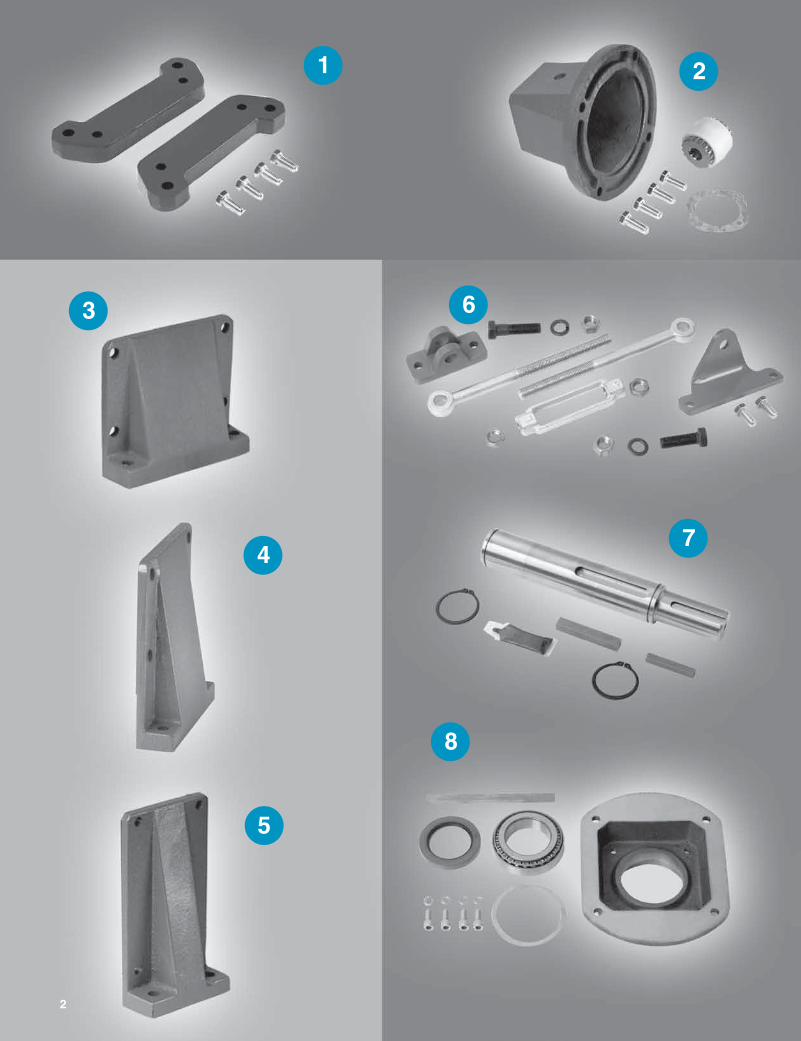
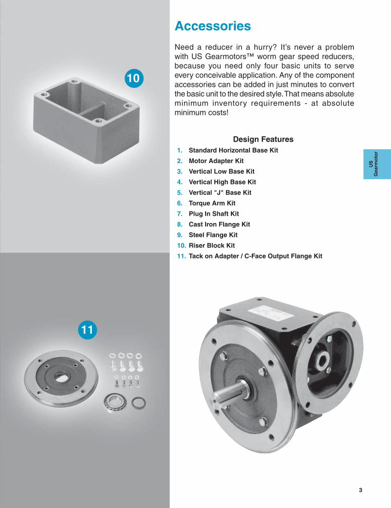
Need a reducer in a hurry? It’s never a problem with US Gearmotors™ worm gear speed reducers, because you need only four basic units to serve every conceivable application. Any of the component accessories can be added in just minutes to convert the basic unit to the desired style. That means absolute minimum inventory requirements - at absolute minimum costs!
Design Features1. Standard Horizontal Base Kit
2. Motor Adapter Kit
3. Vertical Low Base Kit
4. Vertical High Base Kit
5. Vertical "J" Base Kit
6. Torque Arm Kit
7. Plug In Shaft Kit
8. Cast Iron Flange Kit
9. Steel Flange Kit
10. Riser Block Kit
11. Tack on Adapter / C-Face Output Flange Kit
10
11
Accessories
4
NIDEC MOTOR CORPORATION
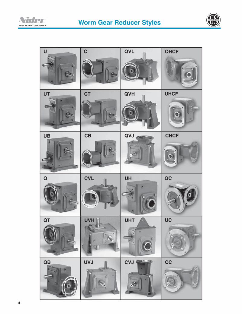
U
C
QVL
UT
CT
QVH
QVJ
CB
UB
Q
CVL
UH
UHT
UVH
QT
QB
UVJ
CVJ
Worm Gear Reducer Styles
QHCF
UHCF
CHCF
QC
UC
CC

5
US
G
earm
oto
r
NIDEC MOTOR CORPORATION
QH
UHMT
QHVH
QHT
UHMB
UHVL
QHVJ
CHVL
UHVH
QHMT
QHMB
UHVJ
CHVH
QHVL
CHMT
CHT
Components
Worm Gear Reducer Styles
QRT
QHP
UHP
CHP
6
NIDEC MOTOR CORPORATION
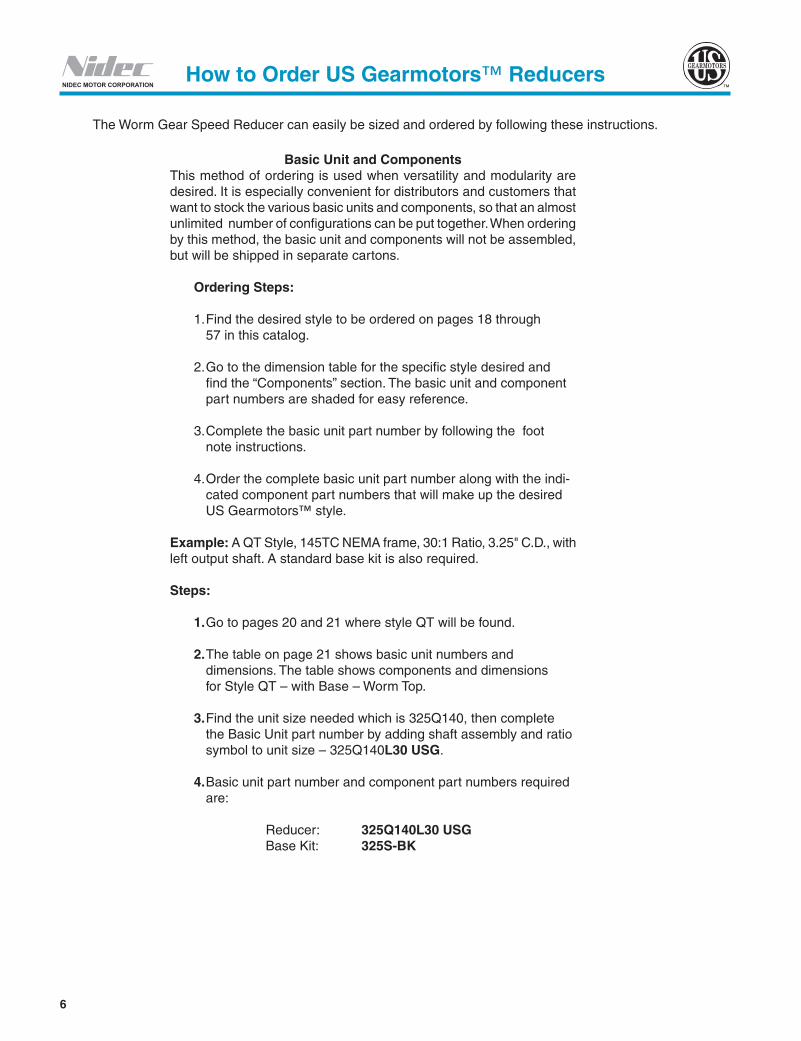
Basic Unit and ComponentsThis method of ordering is used when versatility and modularity are desired. It is especially convenient for distributors and customers that want to stock the various basic units and components, so that an almost unlimited number of configurations can be put together. When ordering by this method, the basic unit and components will not be assembled, but will be shipped in separate cartons.
Ordering Steps:
1. Find the desired style to be ordered on page s 18 through 57 in this catalog.
2. Go to the dimension table for the specific style desired and find the “Components” section. The basic unit and component part numbers are shaded for easy reference.
3. Complete the basic unit part number by following the foot note instructions.
4. Order the complete basic unit part number along with the indi- cated component part numbers that will make up the desired US Gearmotors™ style.
Example: A QT Style, 145TC NEMA frame, 30:1 Ratio, 3.25" C.D., with left output shaft. A standard base kit is also required.
Steps:
1. Go to pages 20 and 21 where style QT will be found.
2. The table on page 21 shows basic unit numbers and dimensions. The table shows components and dimensions for Style QT – with Base – Worm Top.
3. Find the unit size needed which is 325Q140, then complete the Basic Unit part number by adding shaft assembly and ratio symbol to unit size – 325Q140L30 USG.
4. Basic unit part number and component part numbers required are:
Reducer: 325Q140L30 USG Base Kit: 325S-BK
The Worm Gear Speed Reducer can easily be sized and ordered by following these instructions.
How to Order US Gearmotors™ Reducers

NIDEC MOTOR CORPORATION
7
US
G
earm
oto
r
Center Type of C Face O.P. Shaft Ratio BrandDistance Input Size Arrangement (if applicable) 133 Q 56 LR 30 USG
1.33"=133 U = Universal, Shaft In 56C = 56 L = Left Output 5 1.75"=175 Q = C Face Quilled 143/145TC = 140 R = Right Output 10 2.06"=206 182/184TC = 180 LR = Left & Right Output 15 2.62"=262 213/215TC = 210 H = Hollow Output 20 3.25"=325 25 3.75"=375 30 4.50"=450 40 50 60
It is recommended to use the above chart to arrive at US Gearmotors™ reducer part description.The above sample part description is 133Q56LR30 USG. This description does not include feet or other available mounting accessories that are available for the US Gearmotors™ product. These accessories are sold separately using the part descriptions for the appropriate product. Not all ratios are available in each configuration.
US Gearmotors™ units ordered with hollow outputs have a stock bore for each C.D.
Kit Descriptions
NEMA Frame Adapter Kit 375 MAK 56 56 = NEMA size 56 C Face
MAK = Motor Adapter Kit
375 = Fits 3.75" C.D. Reducer
Torque Arm Kit 133 H - TAK TAK = Torque Arm Kit
H = Generally used with Hollow Output Reducers (not limited to)
133 = Fits 1.33" C.D. Reducer
Adjustable Torque Arm Kit 133-175 ATAK ATAK = Adjustable Torque Arm Kit
133-175 = Fits Units 1.33"-1.75" C.D.
Plug In Shaft 175 H - SK SK = Shaft Kit
H = Hollow Output
175 = Fits 1.75" CD Reducer
Cast Iron Flange Kit 175 H - CFK CFK = Cast Iron Flange Kit
H = Hollow Output
175 = Fits 1.75" CD Reducer
Standard Base Kit 206 S-BK S-BK = Standard Base Kit
206 = Fits 2.06" C.D. Reducer
Vertical Low Base Kit 262 VL-BK VL-BK = Vertical Low Base Kit
262 = Fits 2.62" C.D. Reducer Vertical High Base Kit 262 VH-BK VH-BK = Vertical High Base Kit
262 = Fits 2.62" C.D. Reducer
Vertical “J” Base Kit 262 VJ-BK VJ-BK = Vertical “J” Base Kit
262 = Fits 2.62" C.D. Reducer
C-Face Output Kit 175 TAD Q140 Q140 = NEMA Size 140C C-Face Motor Size
TAD = Tack on Adapter
175 = Fits 1.75" CD Reducer
How to Order US Gearmotors™ Reducers
Part Description Configuration
8
NIDEC MOTOR CORPORATIONReducer Selection Procedure
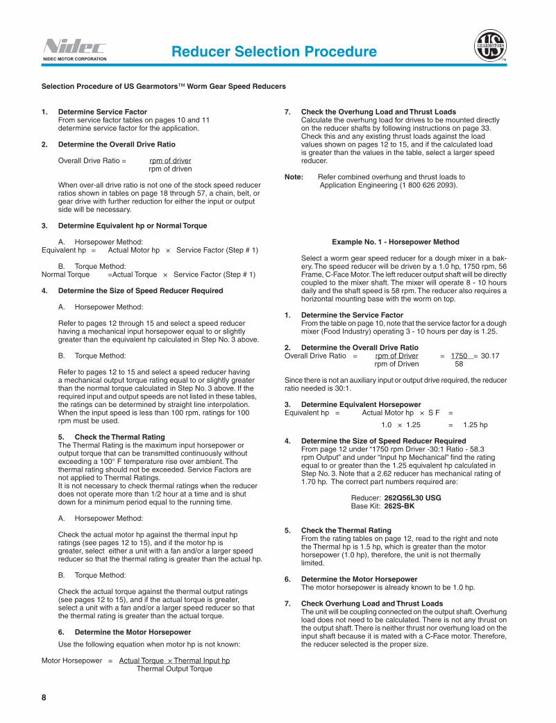
1. Determine Service Factor From service factor tables on pages 10 and 11 determine service factor for the application.
2. Determine the Overall Drive Ratio Overall Drive Ratio = rpm of driver rpm of driven
When over-all drive ratio is not one of the stock speed reducer ratios shown in tables on page 18 through 57, a chain, belt, or gear drive with further reduction for either the input or output side will be necessary.
3. Determine Equivalent hp or Normal Torque A. Horsepower Method:Equivalent hp = Actual Motor hp × Service Factor (Step # 1)
B. Torque Method:Normal Torque = Actual Torque × Service Factor (Step # 1) 4. Determine the Size of Speed Reducer Required A. Horsepower Method:
Refer to pages 12 through 15 and select a speed reducer having a mechanical input horsepower equal to or slightly greater than the equivalent hp calculated in Step No. 3 above.
B. Torque Method:
Refer to pages 12 to 15 and select a speed reducer having a mechanical output torque rating equal to or slightly greater than the normal torque calculated in Step No. 3 above. If the required input and output speeds are not listed in these tables, the ratings can be determined by straight line interpolation. When the input speed is less than 100 rpm, ratings for 100 rpm must be used.
5. Check the Thermal Rating The Thermal Rating is the maximum input horsepower or output torque that can be transmitted continuously without exceeding a 100° F temperature rise over ambient. The thermal rating should not be exceeded. Service Factors are not applied to Thermal Ratings. It is not necessary to check thermal ratings when the reducer does not operate more than 1/2 hour at a time and is shut down for a minimum period equal to the running time.
A. Horsepower Method:
Check the actual motor hp against the thermal input hp ratings (see pages 12 to 15), and if the motor hp is greater, select either a unit with a fan and/or a larger speed reducer so that the thermal rating is greater than the actual hp.
B. Torque Method:
Check the actual torque against the thermal output ratings (see pages 12 to 15), and if the actual torque is greater, select a unit with a fan and/or a larger speed reducer so that the thermal rating is greater than the actual torque.
6. Determine the Motor Horsepower
Use the following equation when motor hp is not known: Motor Horsepower = Actual Torque × Thermal Input hp Thermal Output Torque
7. Check the Overhung Load and Thrust LoadsCalculate the overhung load for drives to be mounted directly on the reducer shafts by following instructions on page 33. Check this and any existing thrust loads against the load values shown on pages 12 to 15, and if the calculated load is greater than the values in the table, select a larger speed reducer.
Note: Refer combined overhung and thrust loads to Application Engineering (1 800 626 2093).
Example No. 1 - Horsepower Method
Select a worm gear speed reducer for a dough mixer in a bak-ery. The speed reducer will be driven by a 1.0 hp, 1750 rpm, 56 Frame, C-Face Motor. The left reducer output shaft will be directly coupled to the mixer shaft. The mixer will operate 8 - 10 hours daily and the shaft speed is 58 rpm. The reducer also requires a horizontal mounting base with the worm on top.
1. Determine the Service FactorFrom the table on page 10, note that the service factor for a dough mixer (Food Industry) operating 3 - 10 hours per day is 1.25.
2. Determine the Overall Drive RatioOverall Drive Ratio = rpm of Driver = 1750 = 30.17 rpm of Driven 58 Since there is not an auxiliary input or output drive required, the reducer ratio needed is 30:1.
3. Determine Equivalent HorsepowerEquivalent hp = Actual Motor hp × S F =
1.0 × 1.25 = 1.25 hp
4. Determine the Size of Speed Reducer Required From page 12 under “1750 rpm Driver -30:1 Ratio - 58.3 rpm Output” and under “Input hp Mechanical” find the rating equal to or greater than the 1.25 equivalent hp calculated in Step No. 3. Note that a 2.62 reducer has mechanical rating of 1.70 hp. The correct part numbers required are:
Reducer: 262Q56L30 USG Base Kit: 262S-BK
5. Check the Thermal Rating From the rating tables on page 12, read to the right and note the Thermal hp is 1.5 hp, which is greater than the motor horsepower (1.0 hp), therefore, the unit is not thermally limited.
6. Determine the Motor Horsepower The motor horsepower is already known to be 1.0 hp.
7. Check Overhung Load and Thrust LoadsThe unit will be coupling connected on the output shaft. Overhung load does not need to be calculated. There is not any thrust on the output shaft. There is neither thrust nor overhung load on the input shaft because it is mated with a C-Face motor. Therefore, the reducer selected is the proper size.
Selection Procedure of US Gearmotors™ Worm Gear Speed Reducers

NIDEC MOTOR CORPORATION
9
US
G
earm
oto
r
Example No. 2 - Torque Method
Select a worm gear speed reducer for a belt conveyor (general purpose), not uniformly fed. The speed reducer will be driven by a 1750 rpm electric motor directly connected by a coupling, with a 1.23:1 ratio chain drive from the reducer to the head shaft of the conveyor. The pitch diameter of the driver sprocket mounted on the reducer output shaft is 5.032 inches. The conveyor will operate 10 hours per day, and the head shaft speed is 140 rpm. The reducer will also require a horizontal mounting base with the worm on top. Conveyor calculations indicate that 1710 inch pounds of torque is needed at the conveyor head shaft.
1. Determine the Service Factor From the table on page 10, note that the service factor for a belt conveyor (general purpose) operating 3 - 10 hours per day is 1.25.
2. Determine the Overall Drive RatioOverall Drive Ratio = rpm of Driver = 1750 = 12.5 : 1 rpm of Driven 140
Speed Reducer Ratio = Overall Drive Ratio = 12.5 = 10.16 : 1 Chain Drive Ratio 1.23
3. Determine the Normal Torque The normal torque required for reducer selection is the actual torque required at the reducer output shaft. Therefore, we must convert the 1710 inch pounds of actual torque at the conveyor head shaft to the actual required torque at the reducer output shaft, and then multiply by the service factor.
Actual Torque at Reducer Output Shaft = Actual Torque At Conveyor Head Shaft = 1710 = 1,390 In/lbs. Chain Drive Ratio 1.23 Normal Torque =
Actual Reducer Output Torque × S F =
1,390 × 1.25 = 1738 in/lbs.
4. Determine the Size of Speed Reducer Required From page 12 under “1750 rpm Driver - 10 to 1 ratio - 175 rpm Driven” and under “Mechanical Output Torque” find the rating equal to or greater than the 1738 inch-pounds normal torque calculated in step no. 3. Note that a 3.25 inch center distance reducer has a mechanical rating of 2401 inch-pounds.
5. Check the Thermal Rating From the rating table on page 12, read to the right and note the thermal torque for a 3.25 inch C.D. reducer is 2401 inch- pounds, which is greater than the actual torque at the reducer output shaft (1,390 inch-pounds) calculated in step no. 3. Therefore, a 3.25 inch C.D. unit, which has a thermal rating of 2401 inch-pounds, can be used.
The correct part numbers required are:
Reducer: 325ULR10 USG Base Kit: 325S-BK
6. Determine the Motor HorsepowerMotor Horsepower = Actual Torque X Thermal Input hp Thermal Output Torque = 1,390 × 5.25 2004
= 3.64 Use a 5 horsepower motor.
7. Check Overhung and Thrust Loads OL (See below) = 2 × T × K P.D. of Sprocket
= 2 × 1390 × 1.0 5.032
= 552.50 Pounds
From rating table on page 12, note the maximum overhung load for the output shaft of the 325ULR10 reducer is 2401 lbs., which is greater than the calculated load on shaft of 553 lbs. There is no thrust on the output shaft. There is neither thrust or overhung load on the input shaft because it is direct couple connected. The reducer selection size is ample.
Overhung Loads
When a speed reducer is driven by any belt, chain or gear drive, or when the speed reducer drives a driven unit through a belt, chain or gear drive, overhung loads must not exceed those shown on pages12 through 15. Use the following formula to calculate the overhung loads:
OL = 2TK D
where OL = Overhung Load T = Actual Shaft Torque (inch-pounds) D = P. D. of Sprocket, Sheave , Pulley or
Gear K = 1.0 for Chain Drive = 1.25 for Gear Drive = 1.25 for Gearbelt Drive = 1.50 for V-Belt Drive = 2.50 for Flat Belt Drive
No overhung loads are encountered when the speed reducer is coupling connected to the driver and/or driven machine. However, care should be taken in aligning the shafts to avoid pre-loading bearings in misalignment.
Reducer Selection Procedure

10
NIDEC MOTOR CORPORATION
(Service factors shown apply only if electric or hydraulic motors are used. For single or multi-cylinder engines, see table on next page for conversion.)
Up to 3-10 Over APPLICATION 3 Hrs. Hrs. 10 Hrs. Day Day Day
AGITATORS (Mixers) Pure Liquids ...................................................................– 1.00 1.25Liquids and Solids ............................................................... 1.00 1.25 1.50 Liquids-Variable Density .............................................. 1.00 1.25 1.50BLOWERS Centrifugal ................................................................... 1.00 1.25 – Lobe ............................................................................ 1.00 1.25 1.50 Vane ...............................................................................– 1.00 1.25BREWING AND DISTILLING Bottling Machinery ..........................................................– 1.00 1.25 Brew Kettles, Continuous Duty .......................................– 1.00 1.25 Cookers, Continuous Duty ..............................................– 1.00 1.25 Mash Tubs, Continuous Duty ..........................................– 1.00 1.25 Scale Hopper, Frequent Starts .................................... 1.00 1.25 1.50CAN FILLING MACHINES .....................................................– 1.00 1.25CAR DUMPERS .................................................................. 1.25 1.50 1.75CAR PULLERS .................................................................... 1.00 1.25 1.50CLARIFIERS ..........................................................................– 1.00 1.25CLASSIFIERS ..................................................................... 1.00 1.25 1.50CLAY WORKING MACHINERY Brick Press .................................................................. 1.25 1.50 1.75 Briquette Machine ....................................................... 1.25 1.50 1.75 Pug Mill ........................................................................ 1.00 1.25 1.50COMPACTORS ................................................................... 1.50 1.75 2.00COMPRESSORS Centrifugal ......................................................................– 1.00 1.25 Lobe ............................................................................ 1.00 1.25 1.50 Reciprocating, Multi-Cylinder ...................................... 1.00 1.25 1.50 Reciprocating, Single-Cylinder .................................... 1.25 1.50 1.75CONVEYORS - GENERAL PURPOSE Uniformly Loaded or Fed ................................................– 1.00 1.25 Not Uniformly Fed ........................................................ 1.00 1.25 1.50 Reciprocating or Shaker .............................................. 1.25 1.50 1.75CRANES Dry Dock Main Hoist ........................................................... 1.25 1.50 1.75 Auxiliary ............................................................... 1.25 1.50 1.75 Boom Hoist .......................................................... 1.25 1.50 1.75 Slewing Drive ...................................................... 1.25 1.50 1.75 Traction Drive ...................................................... 1.50 1.50 1.50 Container Main Hoist ............................................................... Refer To Application Engr. Boom Hoist .............................................................. Refer To Application Engr. Trolley Drive ............................................................. Refer To Application Engr. (Gantry Drive) (Traction Drive) ........................................................ Refer To Application Engr. Mill Duty Main Hoist ............................................................... Refer To Application Engr. Auxiliary ................................................................... Refer To Application Engr. Bridge and Trolley Travel ............................................................ Refer To Application Engr. Industrial Duty Main ..................................................................... 1.00 1.25 1.50 Auxiliary ................................................................... Refer To Application Engr. Bridge and Trolley Travel .......................................... Refer To Application Engr.CRUSHER Stone or Ore ................................................................ 1.50 1.75 2.00DREDGES Cable Reels ................................................................. 1.00 1.25 1.50 Conveyors .................................................................... 1.00 1.25 1.50 Cutter Head Drives ...................................................... 1.25 1.50 1.75 Pumps ......................................................................... 1.00 1.25 1.50 Screen Drives .............................................................. 1.25 1.50 1.75 Stackers ....................................................................... 1.00 1.25 1.50 Winches ....................................................................... 1.00 1.25 1.50ELEVATORS Bucket .......................................................................... 1.00 1.25 1.50 Centrifugal Discharge .....................................................– 1.00 1.25 Escalators ........................................................................ Refer To Application Engr. Freight ............................................................................. Refer To Application Engr. Gravity Discharge ...........................................................– 1.00 1.25EXTRUDERS General ........................................................................ 1.25 1.25 1.25 Plastics (a) Variable Speed Drive ..................................... 1.50 1.50 1.50 (b) Fixed Speed Drive.......................................... 1.75 1.75 1.75 Rubber (a) Continuous Screw Operation ......................... 1.50 1.50 1.50 (b) Intermittent Screw Operation ......................... 1.75 1.75 1.75
Up to 3-10 Over APPLICATION 3 Hrs. Hrs. 10 Hrs. Day Day Day
FANS Centrifugal ......................................................................– 1.00 1.25 Cooling Towers ................................................................ Refer To Application Engr. Forced Draft ................................................................. 1.25 1.25 1.25 Induced Draft ............................................................... 1.00 1.25 1.50 Industrial & Mine 1.00 1.25 1.50FEEDERS Apron ..............................................................................– 1.25 1.50 Belt ............................................................................ 1.00 1.25 1.50 Disc ...............................................................................– 1.00 1.25 Reciprocating .............................................................. 1.25 1.50 1.75 Screw........................................................................... 1.00 1.25 1.50FOOD INDUSTRY Cereal Cooker ................................................................– 1.00 1.25 Dough Mixer ................................................................ 1.00 1.25 1.50 Meat Grinders .............................................................. 1.00 1.25 1.50 Slicers .......................................................................... 1.00 1.25 1.50GENERATORS AND EXCITERS ...........................................– 1.00 1.25HAMMER MILLS ................................................................. 1.50 1.50 1.75HOISTS Heavy Duty .................................................................. 1.25 1.50 1.75 Medium Duty ............................................................... 1.00 1.25 1.50 Skip Hoist .................................................................... 1.00 1.25 1.50LAUNDRY TUMBLERS ....................................................... 1.00 1.25 1.50LAUNDRY WASHERS ......................................................... 1.25 1.25 1.50LUMBER INDUSTRY Barkers -Spindle Feed ...................................................... 1.25 1.25 1.25 - Main Drive ......................................................... 1.50 1.50 1.50 Conveyors - Burner .............................................................. 1.25 1.25 1.50 - Main or Heavy Duty ........................................... 1.50 1.50 1.50 - Main Log ........................................................... 1.50 1.50 1.50 - Re-saw, Merry-Go-Round ................................. 1.25 1.25 1.50 - Slab ................................................................... 1.50 1.50 1.75 - Transfer.............................................................. 1.25 1.25 1.50 Chains - Floor .................................................................. 1.50 1.50 1.50 - Green ................................................................ 1.50 1.50 1.50 Cut-Off Saws - Chain ................................................................ 1.50 1.50 1.50 - Drag .................................................................. 1.50 1.50 1.50 Debarking Drums ........................................................ 1.50 1.50 1.75 Feeds - Edger ................................................................. 1.25 1.25 1.50 - Gang ................................................................. 1.50 1.50 1.50 - Trimmer ............................................................. 1.25 1.25 1.50 Log Deck ..................................................................... 1.50 1.50 1.50 Log Hauls-Incline-Well Type ........................................ 1.50 1.50 1.50 Log Turning Devices .................................................... 1.50 1.50 1.50 Planer Feed ................................................................. 1.25 1.25 1.50 Planer Tilting Hoists ..................................................... 1.50 1.50 1.50 Rolls-Live-off Brg.-Roll Cases ..................................... 1.50 1.50 1.50 Sorting Table ................................................................ 1.25 1.25 1.50 Tipple Hoist ................................................................. 1.25 1.25 1.50 Transfers - Chain ................................................................. 1.50 1.50 1.50 - Causeway .......................................................... 1.50 1.50 1.50 Tray Drives ................................................................... 1.25 1.25 1.50 Veneer Lathe Drives ........................................................ Refer To Application Engr.METAL MILLS Draw Bench Carriage and Main Drive ......................... 1.00 1.25 1.50 Runout Table Non-reversing Group Drives .................................................. 1.00 1.25 1.50 Individual Drives ............................................. 1.50 1.50 1.75 Reversing ............................................................ 1.50 1.50 1.75 Slab Pushers ............................................................... 1.25 1.25 1.50 Shears ......................................................................... 1.50 1.50 1.75 Wire Drawing ............................................................... 1.00 1.25 1.50 Wire Winding Machine ................................................. 1.00 1.25 1.50METAL STRIP PROCESSING MACHINERY Bridles ......................................................................... 1.25 1.25 1.50 Coilers & Uncoilers ...................................................... 1.00 1.00 1.25 Edge Trimmers ............................................................ 1.00 1.25 1.50 Flatteners .................................................................... 1.00 1.25 1.50 Loopers(Accumulators) ............................................... 1.00 1.00 1.00 Pinch Rolls .................................................................. 1.00 1.25 1.50 Scrap Choppers........................................................... 1.00 1.25 1.50 Shears ......................................................................... 1.50 1.50 1.75 Slitters ......................................................................... 1.00 1.25 1.50
Service Factors for
Enclosed Worm Gear Applications

11
US
G
earm
oto
r
NIDEC MOTOR CORPORATIONService Factors for
Enclosed Worm Gear Applications Up to 3-10 Over APPLICATION 3 Hrs. Hrs. 10 Hrs. Day Day Day
MILLS, ROTARY TYPE Ball & Rod Spur Ring Gear ................................................... 1.50 1.50 1.75 Helical Ring Gear ................................................ 1.50 1.50 1.50 Direct Connected ................................................. 1.50 1.50 1.75 Cement Kilns ............................................................... 1.50 1.50 1.50 Dryers & Coolers ......................................................... 1.50 1.50 1.50MIXERS, CONCRETE 1.00 1.25 1.50PAPER MILLSAgitator(Mixer) ..................................................................... 1.50 1.50 1.50 Agitator for Pure Liquids .............................................. 1.25 1.25 1.25 Barking Drums ............................................................. 1.75 1.75 1.75 Barkers - Mechanical ................................................... 1.75 1.75 1.75 Beater .......................................................................... 1.50 1.50 1.50 Breaker Stack .............................................................. 1.25 1.25 1.25 Calender ...................................................................... 1.25 1.25 1.25 Chipper ........................................................................ 1.75 1.75 1.75 Chip Feeder ................................................................. 1.50 1.50 1.50 Coating Rolls ............................................................... 1.25 1.25 1.25 Conveyors Chip, Bark, Chemical ........................................... 1.25 1.25 1.25 Log(Including Slab) ............................................. 1.75 1.75 1.75 Couch Rolls ................................................................. 1.25 1.25 1.25 Cutter ........................................................................... 1.75 1.75 1.75 Cylinder Molds ............................................................. 1.25 1.25 1.25 Dryers Paper Machine .................................................... 1.25 1.25 1.25 Conveyor Type ..................................................... 1.25 1.25 1.25 Embosser .................................................................... 1.25 1.25 1.25 Extruder ....................................................................... 1.50 1.50 1.50 Fourdrinier Rolls (Includes Lump Breaker, Dandy Roll, Wire Turning, and Return Rolls) ............... 1.25 1.25 1.25 Jordan ......................................................................... 1.25 1.25 1.25 Kiln Drive ..................................................................... 1.50 1.50 1.50 Mt. Hope Roll ............................................................... 1.25 1.25 1.25 Paper Rolls .................................................................. 1.25 1.25 1.25 Platter .......................................................................... 1.50 1.50 1.50 Presses- Felt & Suction ............................................... 1.25 1.25 1.25 Pulper .......................................................................... 1.50 1.50 1.75 Pumps- Vacuum .......................................................... 1.50 1.50 1.50 Reel (Surface Type) ..................................................... 1.25 1.25 1.50 Screens Chip ..................................................................... 1.50 1.50 1.50 Rotary .................................................................. 1.50 1.50 1.50 Vibrating .............................................................. 1.75 1.75 1.75 Size Press ................................................................... 1.25 1.25 1.25 Super Calender (See Note) ......................................... 1.25 1.25 1.25 Thickener (AC Motor) ........................................................... 1.50 1.50 1.50 (DC Motor) ........................................................... 1.25 1.25 1.25 Washer (AC Motor) ........................................................... 1.50 1.50 1.50 (DC Motor) ........................................................... 1.25 1.25 1.25 Wind and Unwind Stand .............................................. 1.00 1.00 1.00 Winders (Surface Type) ............................................... 1.25 1.25 1.25 Yankee Dryers ............................................................ 1.25 1.25 1.25PLASTICS INDUSTRY - PRIMARY PROCESSING Intensive Internal Mixers (a) Batch Mixers .................................................. 1.75 1.75 1.75 (b) Continuous Mixers ......................................... 1.50 1.50 1.50 Batch Drop Mill - 2 Smooth Rolls ................................ 1.25 1.25 1.25 Continuous Feed, Holding & Blend Mill ....................... 1.25 1.25 1.25 Compounding Mills ...................................................... 1.25 1.25 1.25 Calenders .................................................................... 1.50 1.50 1.50PLASTICS INDUSTRY - SECONDARY PROCESSING Blow Molders ............................................................... 1.50 1.50 1.50 Coating ........................................................................ 1.25 1.25 1.25 Film ............................................................................ 1.25 1.25 1.25 Pipe ............................................................................ 1.25 1.25 1.25 Pre-Plasticizers............................................................ 1.50 1.50 1.50 Rods ............................................................................ 1.25 1.25 1.25 Sheet ........................................................................... 1.25 1.25 1.25 Tubing .......................................................................... 1.25 1.25 1.50PULLERS - BARGE HAUL .................................................. 1.00 1.50 1.75PUMPS Centrifugal ......................................................................– 1.00 1.25 Proportioning ............................................................... 1.00 1.25 1.50 Reciprocating Single Acting, 3 or More Cylinders ...................... 1.00 1.25 1.50 Double Acting, 2 or More Cylinders ..................... 1.00 1.25 1.50 Rotary - Gear Type .............................................................– 1.00 1.50 - Lobe .....................................................................– 1.00 1.25 - Vane .....................................................................– 1.00 1.25RUBBER INDUSTRY Intensive Internal Mixers (a) Batch Mixers ................................................. 1.50 1.75 1.75 (b) Continuous Mixers ........................................ 1.25 1.50 1.50 Mixing Mill - 2 Smooth Rolls - (If corrugated rolls are used, then use the same service factors that are used for a Cracker-Warmer) ............... 1.50 1.50 1.50 Batch Drop Mill - 2 Smooth Rolls ................................ 1.50 1.50 1.50 Cracker Warmer - 2 Roll: 1 Corrugated Roll ................ 1.75 1.75 1.75 Cracker - 2 Corrugated Rolls ....................................... 1.75 1.75 1.75
Up to 3-10 Over APPLICATION 3 Hrs. Hrs. 10 Hrs. Day Day Day
RUBBER INDUSTRY (Cont'd.) Holding, Feed and Blend Mill - 2 Rolls ........................ 1.25 1.25 1.25 Refiner - 2 Rolls ........................................................... 1.50 1.50 1.50 Calenders .................................................................... 1.50 1.50 1.50SAND MILLER 1.00 1.25 1.50 SEWAGE DISPOSAL EQUIPMENT Bar Screens ....................................................................– 1.00 1.25 Chemical Feeders ..........................................................– 1.00 1.25SEWAGE DISPOSAL EQUIPMENT (Cont'd.) Dewatering Screens .................................................... 1.00 1.25 1.50 Scum Breakers ............................................................ 1.00 1.25 1.50 Slow Or Rapid Mixers .................................................. 1.00 1.25 1.50 Sludge Collectors ........................................................ 1.00 1.00 1.25 Thickener ..................................................................... 1.00 1.25 1.50 Vacuum Filters ............................................................. 1.00 1.25 1.50SCREENS Air Washing ....................................................................– 1.00 1.25 Rotary - Stone Or Gravel ............................................. 1.00 1.25 1.50 Traveling Water Intake ....................................................– 1.00 1.25SUGAR INDUSTRY Beet Slicer ................................................................... 1.50 1.50 1.75 Cane Knives ................................................................ 1.50 1.50 1.50 Crushers ...................................................................... 1.50 1.50 1.50 Mills (Low Speed End)................................................. 1.50 1.50 1.50TEXTILE INDUSTRY Batchers ...................................................................... 1.00 1.25 1.50 Calenders .................................................................... 1.00 1.25 1.50 Cards ........................................................................... 1.00 1.25 1.50 Dry Cans ..................................................................... 1.00 1.25 1.50 Dryers .......................................................................... 1.00 1.25 1.50 Dyeing Machinery ........................................................ 1.00 1.25 1.50 Looms .......................................................................... 1.00 1.25 1.50 Mangles ....................................................................... 1.00 1.25 1.50 Nappers ....................................................................... 1.00 1.25 1.50 Pads ............................................................................ 1.00 1.25 1.50 Slashers ...................................................................... 1.00 1.25 1.50 Soapers ....................................................................... 1.00 1.25 1.50 Spinners ...................................................................... 1.00 1.25 1.50 Tenter Frames.............................................................. 1.00 1.25 1.50 Washers ...................................................................... 1.00 1.25 1.50 Winders ....................................................................... 1.00 1.25 1.50
Anti-Friction Bearings Only.
Note: A Service Factor of 1.0 may be applied at the base of a super calender, operating over a speed range where part of the range is constant horsepower and part of the range is constant torque, provided that the constant horsepower part is greater than 1.5 to 1. A service factor of 1.25 is applicable to super calenders operating over the entire speed range at constant torque, or where the constant horsepower speed range is less than 1.5 to 1.
Duration of Service (Hours Per Day)
Uniform Load
Moderate Shock
Heavy Shock
Extreme Shock
Occasional 1/2 Hour - - 1.0 1.25
Less Than 3 Hours 1.0 1.0 1.25 1.50
3 - 10 Hours 1.0 1.25 1.50 1.75
Over 10 Hours 1.25 1.50 1.75 2.00
Conversion Table for Single or Multi-Cylinder Engines to find Equivalent Single or Multi-Cylinder Service Factor
Load and operating characteristics of both the driver and driven units must be considered throughly when selecting speed reducers. It is essential that all speed reducers be selected for maximum load conditions to be encountered. Worm gear speed reducers will safely transmit momentary starting loads as great as 300% of the mechanical input ratings.
Service Factors for Electric and Hydraulic Motors(For Service Factors For Single Or Multi-Cylinder Engines, see below)
Hydraulic or Electric Motor
Single Cylinder Engines
Multi-Cylinder Engines
1.00 1.50 1.25
1.25 1.75 1.50
1.50 2.00 1.75
1.75 2.25 2.00
2.00 2.50 2.25
12
NIDEC MOTOR CORPORATION
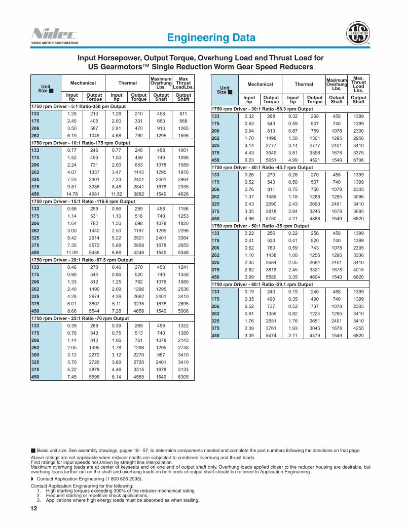
Input Horsepower, Output Torque, Overhung Load and Thrust Load forUS Gearmotors™ Single Reduction Worm Gear Speed Reducers
Engineering Data
Basic unit size. See assembly drawings, pages 18 - 57, to determine components needed and complete the part numbers following the directions on that page.
Above ratings are not applicable when reducer shafts are subjected to combined overhung and thrust loads.Find ratings for input speeds not shown by straight line interpolation.Maximum overhung loads are at center of keyseats and on one end of output shaft only. Overhung loads applied closer to the reducer housing are desirable, but overhung loads farther out on the shaft and overhung loads on both ends of output shaft should be referred to Application Engineering.
Contact Application Engineering (1 800 626 2093).
Contact Application Engineering for the following: 1. High starting torques exceeding 300% of the reducer mechanical rating. 2. Frequent starting or repetitive shock applications. 3. Applications where high energy loads must be absorbed as when stalling.
Unit Size
Mechanical ThermalMaximum Overhung
Lbs.Max
Thrust LoadLbs.
Input hp
Output Torque
Input hp
Output Torque
Output Shaft
Output Shaft
1750 rpm Driver - 5:1 Ratio-350 pm Output133 1.28 210 1.28 210 458 811175 2.45 405 2.00 331 663 868206 3.50 587 2.81 470 913 1265262 6.19 1045 4.68 790 1295 15961750 rpm Driver - 10:1 Ratio-175 rpm Output133 0.77 246 0.77 246 458 1001175 1.52 493 1.50 459 740 1098206 2.24 731 2.00 653 1078 1580262 4.07 1337 3.47 1143 1295 1976325 7.23 2401 7.23 2401 2401 2964375 9.81 3286 8.48 2841 1678 2335450 14.78 4981 11.52 3882 1549 46261750 rpm Driver - 15:1 Ratio -116.6 rpm Output133 0.56 259 0.56 259 458 1156175 1.14 531 1.10 516 740 1253206 1.64 782 1.50 698 1078 1820262 3.00 1440 2.50 1197 1295 2296325 5.42 2614 5.22 2521 2401 3364375 7.35 3572 5.88 2858 1678 2655450 11.09 5436 8.66 4246 1549 53461750 rpm Driver - 20:1 Ratio -87.5 rpm Output133 0.46 270 0.46 270 458 1241175 0.90 544 0.86 520 740 1358206 1.33 812 1.25 762 1078 1980262 2.40 1490 2.09 1296 1295 2536325 4.28 2674 4.26 2662 2401 3410375 6.01 3807 5.11 3235 1678 2895450 8.66 5544 7.28 4658 1549 59061750 rpm Driver - 25:1 Ratio -70 rpm Output133 0.39 269 0.39 269 458 1322175 0.76 543 0.75 513 740 1380206 1.14 812 1.06 761 1078 2143262 2.05 1495 1.78 1298 1295 2748300 3.12 2270 3.12 2270 987 3410325 3.70 2726 3.69 2720 2401 3410375 5.22 3878 4.46 3315 1678 3133450 7.45 5598 6.14 4589 1549 6305
Unit Size
Mechanical ThermalMaximum Overhung
Lbs.
Max. Thrust Load Lbs.
Input hp
Output Torque
Input hp
Output Torque
Output Shaft
Output Shaft
1750 rpm Driver - 30:1 Ratio -58.3 rpm Output133 0.32 268 0.32 268 458 1399175 0.63 543 0.59 507 740 1399206 0.94 813 0.87 759 1078 2300262 1.70 1498 1.50 1301 1295 2956325 3.14 2777 3.14 2777 2401 3410375 4.43 3949 3.81 3396 1678 3375450 6.23 5651 4.99 4521 1549 67061750 rpm Driver - 40:1 Ratio -43.7 rpm Output133 0.26 270 0.26 270 458 1399175 0.52 543 0.50 507 740 1399206 0.76 811 0.75 756 1078 2305262 1.37 1489 1.18 1288 1295 3096325 2.43 2690 2.43 2690 2401 3410375 3.35 3818 2.84 3245 1678 3695450 4.96 5750 4.21 4888 1549 68201750 rpm Driver - 50:1 Ratio -35 rpm Output133 0.22 256 0.22 256 458 1399175 0.41 520 0.41 520 740 1399206 0.62 780 0.59 743 1078 2305262 1.10 1438 1.00 1256 1295 3336325 2.05 2684 2.05 2684 2401 3410375 2.82 3818 2.45 3321 1678 4015450 3.99 5589 3.35 4694 1549 68201750 rpm Driver - 60:1 Ratio -29.1 rpm Output133 0.19 240 0.19 240 458 1399175 0.35 490 0.35 490 740 1399206 0.52 737 0.52 737 1078 2305262 0.91 1359 0.82 1224 1295 3410325 1.76 2651 1.76 2651 2401 3410375 2.39 3761 1.93 3045 1678 4255450 3.39 5474 2.71 4379 1549 6820

13
US
G
earm
oto
r
NIDEC MOTOR CORPORATION
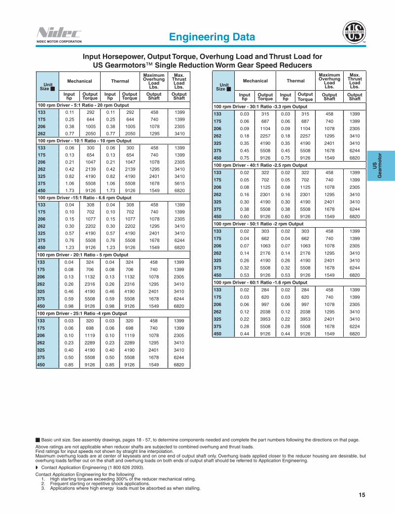
Input Horsepower, Output Torque, Overhung Load and Thrust Load forUS Gearmotors™ Single Reduction Worm Gear Speed Reducers
Basic unit size. See assembly drawings, pages 18 - 57, to determine components needed and complete the part numbers following the directions on that page.
Above ratings are not applicable when reducer shafts are subjected to combined overhung and thrust loads.Find ratings for input speeds not shown by straight line interpolation.Maximum overhung loads are at center of keyseats and on one end of output shaft only. Overhung loads applied closer to the reducer housing are desirable, but overhung loads farther out on the shaft and overhung loads on both ends of output shaft should be referred to Application Engineering (1 800 626 2093).
Contact Application Engineering (1 800 626 2093).
Contact Application Engineering for the following: 1. High starting torques exceeding 300% of the reducer mechanical rating. 2. Frequent starting or repetitive shock applications. 3. Applications where high energy loads must be absorbed as when stalling.
Engineering Data
UnitSize
Mechanical ThermalMaximum Overhung
Load Lbs.
Max. Thrust Load Lbs.
Inputhp
OutputTorque
Inputhp
OutputTorque
OutputShaft
OutputShaft
1160 rpm Driver - 5:1 Ratio-232 rpm Output133 0.96 236 0.96 236 458 916175 1.93 477 1.62 401 740 973206 2.83 708 2.32 580 1078 1415262 5.15 1299 4.02 1014 1295 17761160 rpm Driver - 10:1 Ratio-116 rpm Output133 0.56 263 0.56 263 458 1151175 1.13 547 1.11 534 740 1238206 1.72 836 1.60 776 1078 1740262 3.23 1578 3.02 1477 1295 2216325 6.03 2961 6.03 2961 2401 3284375 8.12 4045 7.07 3519 1678 2575450 12.20 6115 9.76 4892 1549 51061160 rpm Driver - 15:1 Ratio -77.3 rpm Output133 0.40 276 0.40 276 458 1311175 0.86 589 0.83 563 740 1399206 1.27 881 1.18 819 1078 2060262 2.36 1677 2.08 1481 1295 2536325 4.45 3171 4.31 3076 2401 3410375 6.16 4425 5.05 3629 1678 2975450 9.23 6693 7.38 5355 1549 59061160 rpm Driver - 20:1 Ratio-58 rpm Output133 0.34 288 0.34 288 458 1399175 0.67 599 0.67 599 740 1399206 1.03 916 1.03 916 1078 2220262 1.92 1748 1.84 1672 1295 2776325 3.56 3275 3.56 3275 2401 3410375 4.82 4499 4.23 3959 1678 3295450 7.27 6856 6.25 5896 1549 65461160 rpm Driver - 25:1 Ratio -46.4 rpm Output133 0.34 288 0.34 288 458 1399175 0.67 599 0.67 599 740 1399206 1.03 916 1.03 916 1078 2220262 1.92 1748 1.84 1672 1295 2776325 3.56 3275 3.56 3275 2401 3410375 4.82 4499 4.23 3959 1678 3295450 7.27 6856 6.25 5896 1549 6546
Unit Size
Mechanical ThermalMaximum Overhung
Load Lbs.
Max. ThrustLoad Lbs.
Inputhp
OutputTorque
Inputhp
OutputTorque
OutputShaft
OutputShaft
1160 rpm Driver - 30:1 Ratio -38.6 rpm Output133 0.24 284 0.24 284 458 1399175 0.48 591 0.48 591 740 1399206 0.74 911 0.74 911 1078 2305262 1.36 1740 1.25 1612 1295 3176325 2.54 3296 2.54 3296 2401 3410375 3.53 4582 3.04 3940 1678 3775450 5.25 6937 4.31 5690 1549 68201160 rpm Driver - 40:1 Ratio - 29 rpm Output 133 0.20 287 0.20 287 458 1399 175 0.39 599 0.39 599 740 1399 206 0.59 914 0.59 914 1078 2305 262 1.11 1745 1.03 1631 1295 3176 325 2.06 3270 2.06 3270 2401 3410 375 2.73 4516 2.37 3929 1678 4175 450 4.10 6887 3.53 5923 1549 6820 1160 rpm Driver -50:1 Ratio -23.2 rpm Output 133 0.16 273 0.16 273 458 1399 175 0.32 569 0.32 569 740 1399 206 0.48 874 0.48 874 1078 2305 262 0.90 1663 0.82 1511 1295 3410 325 1.67 3144 1.67 3144 2401 3410 375 2.22 4333 1.95 3814 1678 4495 450 3.30 6610 2.84 5685 1549 6820 1160 rpm Driver -60:1 Ratio -19.3 rpm Output 133 0.14 258 0.14 258 458 1399 175 0.27 534 0.27 534 740 1399 206 0.40 822 0.40 822 1078 2305 262 0.74 1571 0.67 1438 1295 3410 325 1.38 2977 1.38 2977 2401 3410 375 1.81 4094 1.52 3438 1678 4815 450 2.70 6246 2.24 5184 1549 6820

14
NIDEC MOTOR CORPORATION
Input Horsepower, Output Torque, Overhung Load and Thrust Load forUS Gearmotors™ Single Reduction Worm Gear Speed Reducers
Basic unit size. See assembly drawings, pages 18 - 57, to determine components needed and complete the part numbers following the directions on that page.
Above ratings are not applicable when reducer shafts are subjected to combined overhung and thrust loads.Find ratings for input speeds not shown by straight line interpolation.Maximum overhung loads are at center of keyseats and on one end of output shaft only. Overhung loads applied closer to the reducer housing are desirable, but overhung loads farther out on the shaft and overhung loads on both ends of output shaft should be referred to Application Engineering.
Contact Application Engineering (1 800 626 2093).
Contact Application Engineering for the following: 1. High starting torques exceeding 300% of the reducer mechanical rating. 2. Frequent starting or repetitive shock applications. 3. Applications where high energy loads must be absorbed as when stalling.
Engineering Data
Unit Size
Mechanical ThermalMaximum Overhung
Load Lbs.
Max. Thrust Load Lbs.
Input hp
Output Torque
Input hp
OutputTorque
OutputShaft
OutputShaft
690 rpm Driver -5:1 Ratio -138 rpm Output 133 0.65 261 0.65 261 458 1071 175 1.34 548 1.18 482 740 1118 206 2.02 832 1.74 715 1078 1650 262 3.83 1591 3.14 1305 1295 2056 690 rpm Driver - 10:1 Ratio - 69 rpm Output 133 0.36 279 0.36 279 458 1321 175 0.75 593 0.75 593 740 1399 206 1.17 924 1.17 924 1078 2060 262 2.27 1813 2.27 1813 1295 2616 325 4.43 3577 3.80 3061 2401 3410 375 6.01 4926 4.65 3813 1678 2975 450 9.30 7684 7.62 6301 1549 5906 690 rpm Driver -15:1 Ratio -46 rpm Output 133 0.26 290 0.26 290 458 1399 175 0.57 637 0.57 637 740 1399 206 0.85 966 0.85 966 1078 2305 262 1.64 1895 1.56 1801 1295 2936 325 3.25 3773 2.57 2990 2401 3410 375 4.59 5400 3.85 4536 1678 3375 450 7.11 8432 5.83 6914 1549 6786 690 rpm Driver -20:1 Ratio -34.5 rpm Output 133 0.22 315 0.22 315 458 1399 175 0.45 645 0.45 645 740 1399 206 0.70 1009 0.70 1009 1078 2305 262 1.40 1978 1.38 1949 1295 3256 325 2.63 3906 2.37 3517 2401 3410 375 3.59 5424 3.22 4882 1678 3775 450 5.51 8471 4.85 7455 1549 6820 690 rpm Driver -25:1 Ratio -27.6 rpm Output 133 0.19 322 0.19 322 458 1399 175 0.37 645 0.37 645 740 1399 206 0.59 1007 0.59 1007 1078 2305 262 1.14 1968 1.11 1894 1295 3410 325 2.17 3898 1.95 3509 2401 3410 375 3.06 5503 2.72 4897 1678 4050 450 4.68 8593 4.02 7387 1549 6820
Unit Size
Mechanical ThermalMaximum Overhung
Load Lbs.
Max. Thrust Load Lbs.
Input hp
Output Torque
Input hp
OutputTorque
OutputShaft
OutputShaft
690 rpm Driver - 30:1 Ratio - 23 rpm Output 133 0.15 326 0.15 326 458 1399 175 0.32 649 0.32 649 740 1399 206 0.50 993 0.50 993 1078 2305 237 0.84 1621 0.84 1621 843 2305 262 0.96 1957 0.90 1839 1295 3410 325 1.88 3882 1.69 3494 2401 3410 375 2.70 5579 2.38 4909 1678 4335 450 4.11 8716 3.45 7322 1549 6820 690 rpm Driver - 40:1 Ratio - 17.2 rpm Output 133 0.13 295 0.13 315 458 1399 175 0.26 642 0.26 642 740 1399 206 0.42 1005 0.42 1005 1078 2305 262 0.79 1973 0.79 1973 1295 3410 325 1.55 3898 1.36 3433 2401 3410 375 2.07 5413 1.82 4763 1678 4815 450 3.16 8455 2.72 7271 1549 6820 690 rpm Driver - 50:1 Ratio - 13.8 rpm Output 133 0.11 286 0.11 286 458 1399 175 0.22 609 0.22 609 740 1399 206 0.34 954 0.34 954 1078 2305 262 0.65 1880 0.65 1880 1295 3410 325 1.27 3738 1.13 3335 2401 3410 375 1.67 5135 1.47 4519 1678 5215 450 2.55 8081 2.20 6950 1549 6820 690 rpm Driver - 60:1 Ratio - 11.5 rpm Output 133 0.09 265 0.09 265 458 1399 175 0.19 570 0.19 570 740 1399 206 0.29 897 0.29 897 1078 2305 262 0.54 1767 0.54 1767 1295 3410 325 1.07 3520 1.01 3336 2401 3410 375 1.38 4818 1.16 4047 1678 5615 450 2.10 7575 1.75 6287 1549 3820
15
US
G
earm
oto
r
NIDEC MOTOR CORPORATION
Input Horsepower, Output Torque, Overhung Load and Thrust Load forUS Gearmotors™ Single Reduction Worm Gear Speed Reducers
Basic unit size. See assembly drawings, pages 18 - 57, to determine components needed and complete the part numbers following the directions on that page.
Above ratings are not applicable when reducer shafts are subjected to combined overhung and thrust loads.Find ratings for input speeds not shown by straight line interpolation.Maximum overhung loads are at center of keyseats and on one end of output shaft only. Overhung loads applied closer to the reducer housing are desirable, but overhung loads farther out on the shaft and overhung loads on both ends of output shaft should be referred to Application Engineering.
Contact Application Engineering (1 800 626 2093).
Contact Application Engineering for the following: 1. High starting torques exceeding 300% of the reducer mechanical rating. 2. Frequent starting or repetitive shock applications. 3. Applications where high energy loads must be absorbed as when stalling.
Engineering Data
Unit Size
Mechanical ThermalMaximum Overhung
Load Lbs.
Max. Thrust Load Lbs.
Input hp
Output Torque
Input hp
Output Torque
Output Shaft
Output Shaft
100 rpm Driver - 5:1 Ratio - 20 rpm Output 133 0.11 292 0.11 292 458 1399 175 0.25 644 0.25 644 740 1399 206 0.38 1005 0.38 1005 1078 2305 262 0.77 2050 0.77 2050 1295 3410 100 rpm Driver - 10:1 Ratio - 10 rpm Output 133 0.06 300 0.06 300 458 1399 175 0.13 654 0.13 654 740 1399 206 0.21 1047 0.21 1047 1078 2305 262 0.42 2139 0.42 2139 1295 3410 325 0.82 4190 0.82 4190 2401 3410 375 1.06 5508 1.06 5508 1678 5615 450 1.73 9126 1.73 9126 1549 6820 100 rpm Driver -15:1 Ratio - 6.6 rpm Output 133 0.04 308 0.04 308 458 1399 175 0.10 702 0.10 702 740 1399 206 0.15 1077 0.15 1077 1078 2305 262 0.30 2202 0.30 2202 1295 3410 325 0.57 4190 0.57 4190 2401 3410 375 0.76 5508 0.76 5508 1678 6244 450 1.23 9126 1.23 9126 1549 6820 100 rpm Driver - 20:1 Ratio - 5 rpm Output
133 0.04 324 0.04 324 458 1399
175 0.08 706 0.08 706 740 1399
206 0.13 1132 0.13 1132 1078 2305
262 0.26 2316 0.26 2316 1295 3410
325 0.46 4190 0.46 4190 2401 3410
375 0.59 5508 0.59 5508 1678 6244
450 0.98 9126 0.98 9126 1549 6820
100 rpm Driver - 25:1 Ratio -4 rpm Output
133 0.03 320 0.03 320 458 1399
175 0.06 698 0.06 698 740 1399
206 0.10 1119 0.10 1119 1078 2305
262 0.23 2289 0.23 2289 1295 3410
325 0.40 4190 0.40 4190 2401 3410
375 0.50 5508 0.50 5508 1678 6244
450 0.85 9126 0.85 9126 1549 6820
Unit Size
Mechanical ThermalMaximum Overhung
Load Lbs.
Max. Thrust Load Lbs.
Input hp
Output Torque
Input hp
OutputTorque
Output Shaft
Output Shaft
100 rpm Driver - 30:1 Ratio -3.3 rpm Output
133 0.03 315 0.03 315 458 1399
175 0.06 687 0.06 687 740 1399
206 0.09 1104 0.09 1104 1078 2305
262 0.18 2257 0.18 2257 1295 3410
325 0.35 4190 0.35 4190 2401 3410
375 0.45 5508 0.45 5508 1678 6244
450 0.75 9126 0.75 9126 1549 6820
100 rpm Driver - 40:1 Ratio -2.5 rpm Output
133 0.02 322 0.02 322 458 1399
175 0.05 702 0.05 702 740 1399
206 0.08 1125 0.08 1125 1078 2305
262 0.16 2301 0.16 2301 1295 3410
325 0.30 4190 0.30 4190 2401 3410
375 0.38 5508 0.38 5508 1678 6244
450 0.60 9126 0.60 9126 1549 6820
100 rpm Driver - 50:1 Ratio -2 rpm Output
133 0.02 303 0.02 303 458 1399
175 0.04 662 0.04 662 740 1399
206 0.07 1063 0.07 1063 1078 2305
262 0.14 2176 0.14 2176 1295 3410
325 0.26 4190 0.26 4190 2401 3410
375 0.32 5508 0.32 5508 1678 6244
450 0.53 9126 0.53 9126 1549 6820
100 rpm Driver - 60:1 Ratio -1.6 rpm Output
133 0.02 284 0.02 284 458 1399
175 0.03 620 0.03 620 740 1399
206 0.06 997 0.06 997 1078 2305
262 0.12 2038 0.12 2038 1295 3410
325 0.22 3953 0.22 3953 2401 3410
375 0.28 5508 0.28 5508 1678 6224
450 0.44 9126 0.44 9126 1549 6820

16
Notes
17
US
G
earm
oto
r
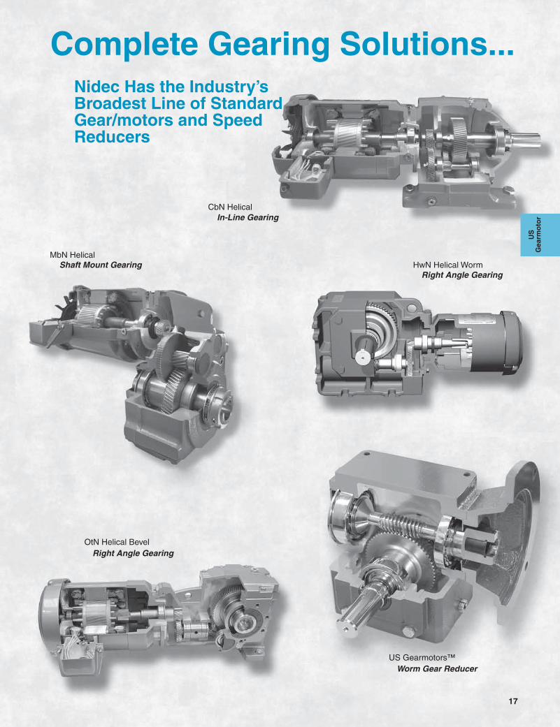
CbN HelicalIn-Line Gearing
MbN HelicalHwN Helical WormShaft Mount Gearing
Right Angle Gearing
US Gearmotors™
OtN Helical Bevel
Worm Gear Reducer
Right Angle Gearing
Nidec Has the Industry’s Broadest Line of Standard Gear/motors and Speed Reducers
Complete Gearing Solutions...
18
NIDEC MOTOR CORPORATION
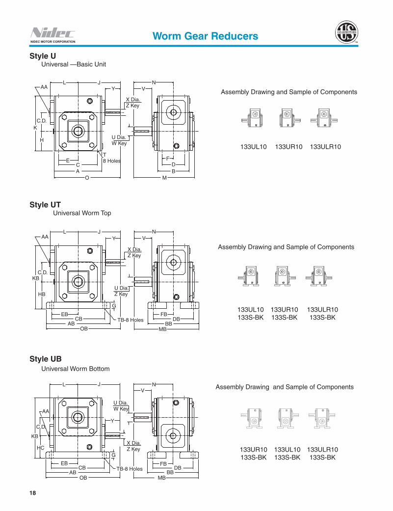
Style U Universal —Basic Unit
Style UT Universal Worm Top
Style UB Universal Worm Bottom
Assembly Drawing and Sample of Components
133UL10 133UR10 133ULR10
Assembly Drawing and Sample of Components
133UL10 133UR10 133ULR10 133S-BK 133S-BK 133S-BK
Assembly Drawing and Sample of Components
133UR10 133UL10 133ULR10 133S-BK 133S-BK 133S-BK
C.D.K
H
ECA
O
T8 Holes
U Dia.W Key
X Dia.Z Key
YJL
VN
MBD
F
AA
AAL J
KBC.D.
HB
EBCB
ABOB
TB-8 Holes
G
U Dia.Z Key
X Dia.Z Key
VYN
FBDB
BBMB
L
AA
C.D.
KB
HC
EBCB
ABOB
TB-8 Holes
G
Y
FB
X Dia.Z Key
U Dia.W Key
J NV
DBBB
MB
Worm Gear Reducers

19
US
G
earm
oto
r
NIDEC MOTOR CORPORATION
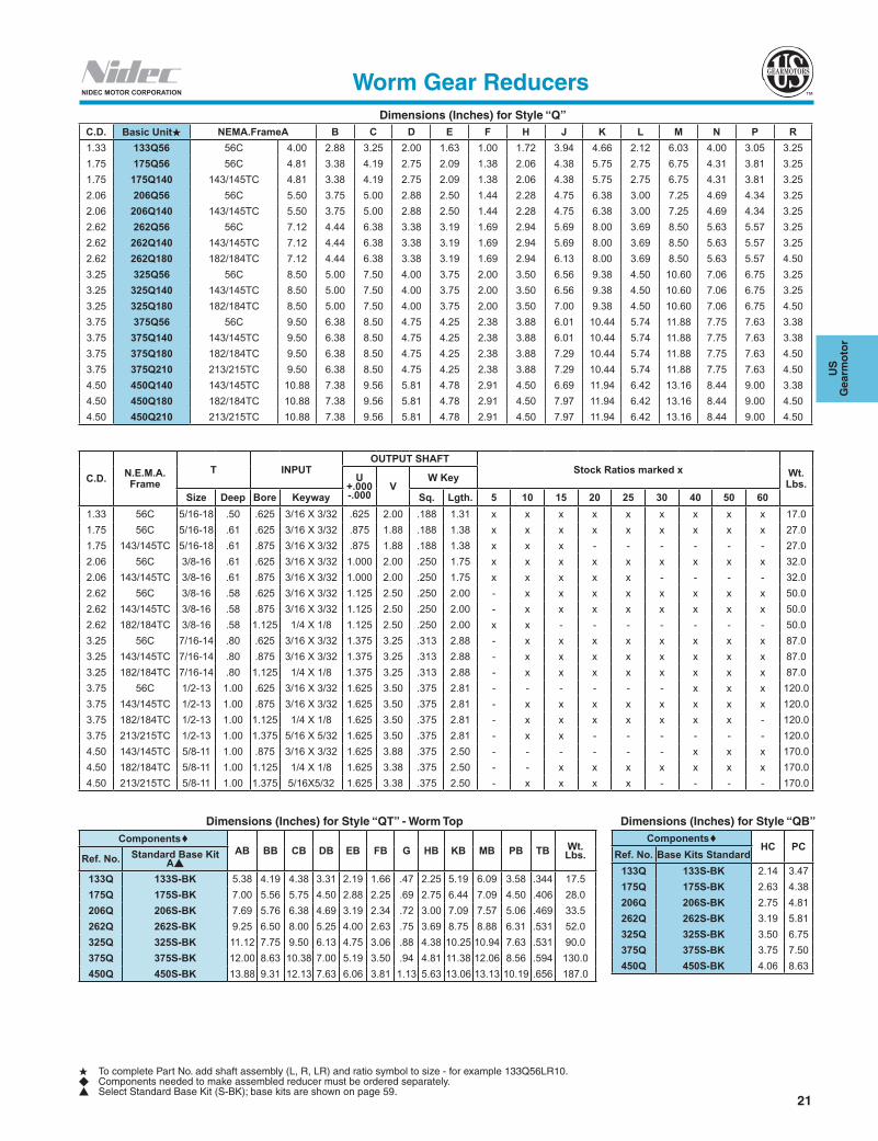
Dimensions (Inches) for Style “U”
H To complete Part No. add shaft assembly (L, R, LR) and ratio symbol to size - for example 133ULR10.u Components needed to make assembled reducer must be ordered separately.s Select either Standard Base Kit (S-BK); base kits are shown on page 59.
Worm Gear Reducers
C.D. Basic Unit* A B C D E F H J K L M N O1.33 133U 4.00 2.88 3.25 2.00 1.63 1.00 1.72 4.03 4.66 2.12 6.03 4.00 6.031.75 175U 4.81 3.38 4.19 2.75 2.09 1.38 2.06 4.68 5.75 2.75 6.75 4.31 7.09
2.06 206U 5.50 3.75 5.00 2.88 2.50 1.44 2.28 5.06 6.38 3.00 7.25 4.69 7.732.62 262U 7.12 4.44 6.38 3.38 3.19 1.69 2.94 6.23 8.00 3.69 8.50 5.63 9.79
3.25 325U 8.50 5.00 7.50 4.00 3.75 2.00 3.50 7.06 9.38 4.50 10.60 7.06 11.313.75 375U 9.50 6.38 8.50 4.75 4.25 2.38 3.88 8.38 10.44 5.74 11.88 7.75 13.134.50 450U 10.88 7.38 9.56 5.81 4.78 2.91 4.50 9.59 11.94 6.42 13.16 8.44 15.09
C.D.T
OUTPUT SHAFT INPUT SHAFTStock Ratios marked “x” Wt.
Lbs.U
+.000 -0.001
VW Key X
+.000 -0.001
YZ Key
Size Deep Sq. Lgth. Sq. Lgth. 5 10 15 20 25 30 40 50 60
1.33 5/16-18 .50 .625 2.00 .188 1.31 .500 1.81 .125 1.38 x x x x x x x x x 11.01.75 5/16-18 .61 .875 1.88 .188 1.38 .625 1.81 .188 1.50 x x x x x x x x x 20.0
2.06 3/8-16 .61 1.000 2.00 .250 1.75 .625 1.81 .188 1.50 x x x x x x x x x 25.02.62 3/8-16 .58 1.125 2.50 .250 2.00 .750 2.31 .188 1.88 x x x x x x x x x 43.0
3.25 7/16-14 .80 1.375 3.25 .313 2.88 .875 2.31 .188 1.63 - x x x x x x x x 72.03.75 1/2-13 1.00 1.625 3.50 .375 2.81 1.000 2.91 .250 1.75 - x x x x x x x x 105.04.50 5/8-11 1.00 1.625 3.38 .375 2.50 1.125 3.48 .250 2.50 - x x x x x x x x 151.0
Dimensions (Inches) for Style “UT” - With Base - Worm TopComponents u
AB BB CB DB EB FB G HB KB MB OB TB Wt. Lbs.Basic Unit H Base Kit s
Standard133U 133S-BK 5.38 4.19 4.38 3.31 2.19 1.66 .47 2.25 5.19 6.09 6.72 .344 11.5175U 175S-BK 7.00 5.56 5.75 4.50 2.88 2.25 .69 2.75 6.44 7.09 8.18 .406 21.0
206U 206S-BK 7.69 5.76 6.38 4.69 3.19 2.34 .72 3.00 7.09 7.57 8.90 .469 26.5262U 262S-BK 9.25 6.50 8.00 5.25 4.00 2.63 .75 3.69 8.75 8.88 10.86 .531 45.0
325U 325S-BK 11.12 7.75 9.50 6.13 4.75 3.06 .88 4.38 10.25 10.94 12.63 .531 75.0375U 375S-BK 12.00 8.63 10.38 7.00 5.19 3.50 .94 4.81 11.38 12.06 14.38 .594 115.0450U 450S-BK 13.88 9.31 12.13 7.63 6.06 3.81 1.13 5.63 13.06 13.13 16.53 .656 168.0
Dimensions (Inches) for Style “UB”
Components uHC
Basic Unit H Base Kit s Standard
133U 133S-BK 2.14175U 175S-BK 2.63
206U 206S-BK 2.75262U 262S-BK 3.19
325U 325S-BK 3.50375U 375S-BK 3.75450U 450S-BK 4.06
20
NIDEC MOTOR CORPORATION
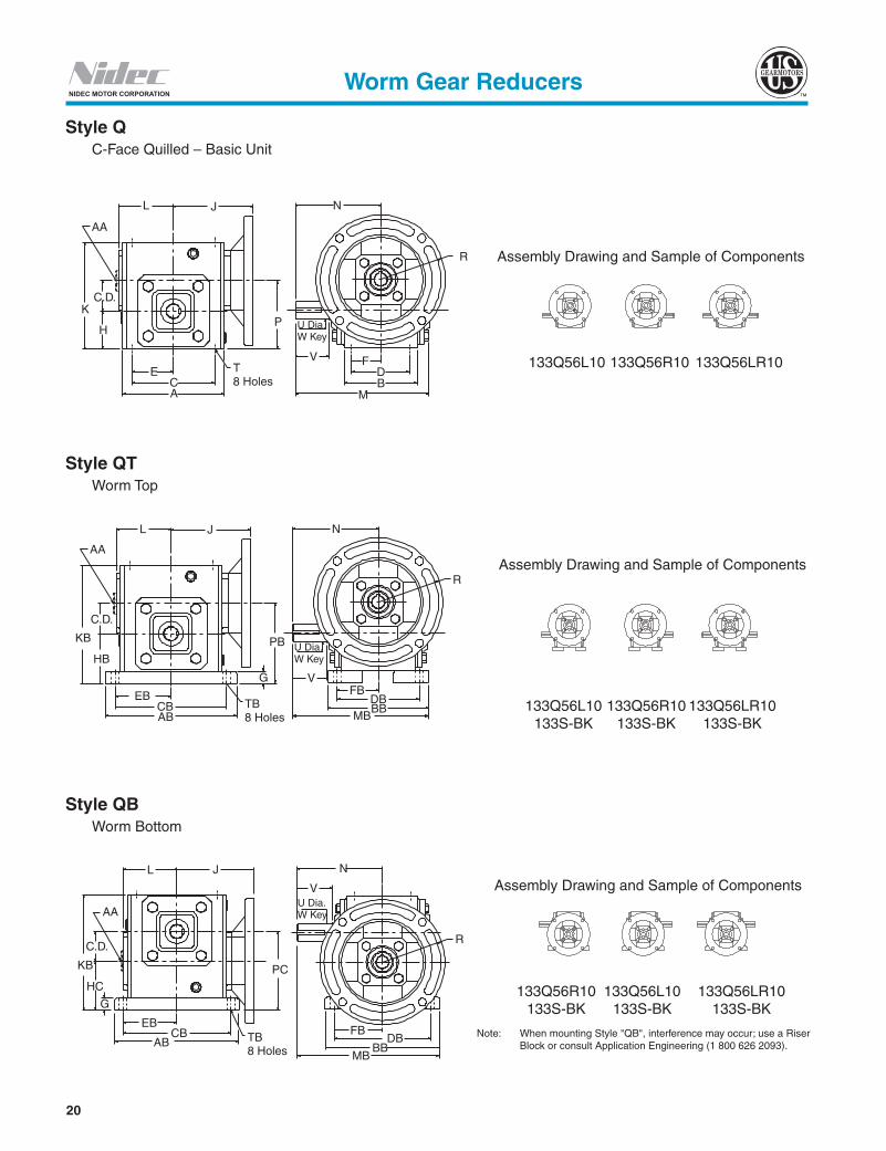
Style QT Worm Top
Style QB Worm Bottom
Style Q C-Face Quilled – Basic Unit
Assembly Drawing and Sample of Components
133Q56L10 133Q56R10 133Q56LR10
Assembly Drawing and Sample of Components
133Q56L10 133Q56R10 133Q56LR10 133S-BK 133S-BK 133S-BK
Assembly Drawing and Sample of Components
133Q56R10 133Q56L10 133Q56LR10 133S-BK 133S-BK 133S-BK
Note: When mounting Style "QB", interference may occur; use a Riser Block or consult Application Engineering (1 800 626 2093).
AA
L J
P
T8 Holes
ECA
H
C.D.K
V
U Dia.W Key
FDB
M
R
N
AA
L J
C.D.
KB
HB
PB
EBCBAB
TB8 Holes
G
U Dia.W Key
VFB
DBBB
MB
R
N
L
AA
J N
V
PCKB
C.D.
HC
G
EBCB
AB TB8 Holes MB
BBDB
FB
R
U Dia.W Key
Worm Gear Reducers
21
US
G
earm
oto
r
NIDEC MOTOR CORPORATION
Dimensions (Inches) for Style “Q”
H To complete Part No. add shaft assembly (L, R, LR) and ratio symbol to size - for example 133Q56LR10.u Components needed to make assembled reducer must be ordered separately.s Select Standard Base Kit (S-BK); base kits are shown on page 59.
Worm Gear Reducers
C.D. N.E.M.A.Frame
T INPUTOUTPUT SHAFT
Stock Ratios marked x Wt.Lbs.U
+.000 -.000
VW Key
Size Deep Bore Keyway Sq. Lgth. 5 10 15 20 25 30 40 50 601.33 56C 5/16-18 .50 .625 3/16 X 3/32 .625 2.00 .188 1.31 x x x x x x x x x 17.01.75 56C 5/16-18 .61 .625 3/16 X 3/32 .875 1.88 .188 1.38 x x x x x x x x x 27.01.75 143/145TC 5/16-18 .61 .875 3/16 X 3/32 .875 1.88 .188 1.38 x x x - - - - - - 27.02.06 56C 3/8-16 .61 .625 3/16 X 3/32 1.000 2.00 .250 1.75 x x x x x x x x x 32.02.06 143/145TC 3/8-16 .61 .875 3/16 X 3/32 1.000 2.00 .250 1.75 x x x x x - - - - 32.02.62 56C 3/8-16 .58 .625 3/16 X 3/32 1.125 2.50 .250 2.00 - x x x x x x x x 50.02.62 143/145TC 3/8-16 .58 .875 3/16 X 3/32 1.125 2.50 .250 2.00 - x x x x x x x x 50.02.62 182/184TC 3/8-16 .58 1.125 1/4 X 1/8 1.125 2.50 .250 2.00 x x - - - - - - - 50.03.25 56C 7/16-14 .80 .625 3/16 X 3/32 1.375 3.25 .313 2.88 - x x x x x x x x 87.03.25 143/145TC 7/16-14 .80 .875 3/16 X 3/32 1.375 3.25 .313 2.88 - x x x x x x x x 87.03.25 182/184TC 7/16-14 .80 1.125 1/4 X 1/8 1.375 3.25 .313 2.88 - x x x x x x x x 87.03.75 56C 1/2-13 1.00 .625 3/16 X 3/32 1.625 3.50 .375 2.81 - - - - - - x x x 120.03.75 143/145TC 1/2-13 1.00 .875 3/16 X 3/32 1.625 3.50 .375 2.81 - x x x x x x x x 120.03.75 182/184TC 1/2-13 1.00 1.125 1/4 X 1/8 1.625 3.50 .375 2.81 - x x x x x x x - 120.03.75 213/215TC 1/2-13 1.00 1.375 5/16 X 5/32 1.625 3.50 .375 2.81 - x x - - - - - - 120.04.50 143/145TC 5/8-11 1.00 .875 3/16 X 3/32 1.625 3.88 .375 2.50 - - - - - - x x x 170.04.50 182/184TC 5/8-11 1.00 1.125 1/4 X 1/8 1.625 3.38 .375 2.50 - - x x x x x x x 170.04.50 213/215TC 5/8-11 1.00 1.375 5/16X5/32 1.625 3.38 .375 2.50 - x x x x - - - - 170.0
Dimensions (Inches) for Style “QT” - Worm TopComponents
AB BB CB DB EB FB G HB KB MB PB TB Wt. Lbs.Ref. No. Standard Base Kit
As
133Q 133S-BK 5.38 4.19 4.38 3.31 2.19 1.66 .47 2.25 5.19 6.09 3.58 .344 17.5175Q 175S-BK 7.00 5.56 5.75 4.50 2.88 2.25 .69 2.75 6.44 7.09 4.50 .406 28.0206Q 206S-BK 7.69 5.76 6.38 4.69 3.19 2.34 .72 3.00 7.09 7.57 5.06 .469 33.5262Q 262S-BK 9.25 6.50 8.00 5.25 4.00 2.63 .75 3.69 8.75 8.88 6.31 .531 52.0325Q 325S-BK 11.12 7.75 9.50 6.13 4.75 3.06 .88 4.38 10.25 10.94 7.63 .531 90.0375Q 375S-BK 12.00 8.63 10.38 7.00 5.19 3.50 .94 4.81 11.38 12.06 8.56 .594 130.0450Q 450S-BK 13.88 9.31 12.13 7.63 6.06 3.81 1.13 5.63 13.06 13.13 10.19 .656 187.0
Dimensions (Inches) for Style “QB”Components
HC PCRef. No. Base Kits Standard
133Q 133S-BK 2.14 3.47175Q 175S-BK 2.63 4.38206Q 206S-BK 2.75 4.81262Q 262S-BK 3.19 5.81325Q 325S-BK 3.50 6.75375Q 375S-BK 3.75 7.50450Q 450S-BK 4.06 8.63
C.D. Basic UnitH NEMA.FrameA B C D E F H J K L M N P R1.33 133Q56 56C 4.00 2.88 3.25 2.00 1.63 1.00 1.72 3.94 4.66 2.12 6.03 4.00 3.05 3.251.75 175Q56 56C 4.81 3.38 4.19 2.75 2.09 1.38 2.06 4.38 5.75 2.75 6.75 4.31 3.81 3.251.75 175Q140 143/145TC 4.81 3.38 4.19 2.75 2.09 1.38 2.06 4.38 5.75 2.75 6.75 4.31 3.81 3.252.06 206Q56 56C 5.50 3.75 5.00 2.88 2.50 1.44 2.28 4.75 6.38 3.00 7.25 4.69 4.34 3.252.06 206Q140 143/145TC 5.50 3.75 5.00 2.88 2.50 1.44 2.28 4.75 6.38 3.00 7.25 4.69 4.34 3.252.62 262Q56 56C 7.12 4.44 6.38 3.38 3.19 1.69 2.94 5.69 8.00 3.69 8.50 5.63 5.57 3.252.62 262Q140 143/145TC 7.12 4.44 6.38 3.38 3.19 1.69 2.94 5.69 8.00 3.69 8.50 5.63 5.57 3.252.62 262Q180 182/184TC 7.12 4.44 6.38 3.38 3.19 1.69 2.94 6.13 8.00 3.69 8.50 5.63 5.57 4.503.25 325Q56 56C 8.50 5.00 7.50 4.00 3.75 2.00 3.50 6.56 9.38 4.50 10.60 7.06 6.75 3.253.25 325Q140 143/145TC 8.50 5.00 7.50 4.00 3.75 2.00 3.50 6.56 9.38 4.50 10.60 7.06 6.75 3.253.25 325Q180 182/184TC 8.50 5.00 7.50 4.00 3.75 2.00 3.50 7.00 9.38 4.50 10.60 7.06 6.75 4.503.75 375Q56 56C 9.50 6.38 8.50 4.75 4.25 2.38 3.88 6.01 10.44 5.74 11.88 7.75 7.63 3.383.75 375Q140 143/145TC 9.50 6.38 8.50 4.75 4.25 2.38 3.88 6.01 10.44 5.74 11.88 7.75 7.63 3.383.75 375Q180 182/184TC 9.50 6.38 8.50 4.75 4.25 2.38 3.88 7.29 10.44 5.74 11.88 7.75 7.63 4.503.75 375Q210 213/215TC 9.50 6.38 8.50 4.75 4.25 2.38 3.88 7.29 10.44 5.74 11.88 7.75 7.63 4.504.50 450Q140 143/145TC 10.88 7.38 9.56 5.81 4.78 2.91 4.50 6.69 11.94 6.42 13.16 8.44 9.00 3.384.50 450Q180 182/184TC 10.88 7.38 9.56 5.81 4.78 2.91 4.50 7.97 11.94 6.42 13.16 8.44 9.00 4.504.50 450Q210 213/215TC 10.88 7.38 9.56 5.81 4.78 2.91 4.50 7.97 11.94 6.42 13.16 8.44 9.00 4.50
22
NIDEC MOTOR CORPORATION
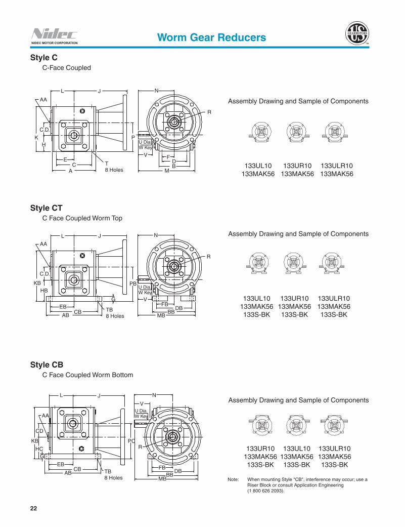
Style C C-Face Coupled
Style CT C Face Coupled Worm Top
Style CB C Face Coupled Worm Bottom
Assembly Drawing and Sample of Components
133UL10 133UR10 133ULR10 133MAK56 133MAK56 133MAK56
Assembly Drawing and Sample of Components
133UR10 133UL10 133ULR10 133MAK56 133MAK56 133MAK56 133S-BK 133S-BK 133S-BK
Assembly Drawing and Sample of Components
133UL10 133UR10 133ULR10 133MAK56 133MAK56 133MAK56 133S-BK 133S-BK 133S-BK
L
AA
J
K
C.D.
E
H
CA
P
V
U Dia.W Key
FDB
M
R
T8 Holes
N
L
AA
J
C.D.
KBHB
EBCB
ABTB8 Holes
G
PB
V
MBBB
DBFB
R
N
U Dia.W Key
L J N
AA
CD
KB
HCG
EBCB
AB TB8 Holes
PC
FB
R
DBBB
MB
VU Dia.W Key
Worm Gear Reducers
Note: When mounting Style "CB", interference may occur; use a Riser Block or consult Application Engineering (1 800 626 2093).

23
US
G
earm
oto
r
NIDEC MOTOR CORPORATION
H To complete Part No. add shaft assembly (L, R, LR) and ratio symbol to size - for example 133ULR10.u Components needed to make assembled reducer must be ordered separately.s Select Standard Base Kit (S-BK); base kits are shown on page 59.
Dimensions (Inches) for Style “C”
Worm Gear Reducers
C.D.Component u
A B C D E F H K L M N PT
Basic UnitH Adapter Kit Size Deep1.33 133U
See Adapter Kit 5/16Table
Below
4.00 2.88 3.25 2.00 1.63 1.00 1.72 4.66 2.12 6.03 4.00 3.05 5/16-18 .501.75 175U 4.81 3.38 4.19 2.75 2.09 1.38 2.06 5.75 2.75 6.75 4.31 3.81 5/16-18 .612.06 206U 5.50 3.75 5.00 2.88 2.50 1.44 2.28 6.38 3.00 7.25 4.69 4.34 3/8-16 .612.62 262U 7.12 4.44 6.38 3.38 3.19 1.69 2.94 8.00 3.69 8.50 5.63 5.57 3/8-16 .583.25 325U 8.50 5.00 7.50 4.00 3.75 2.00 3.50 9.38 4.50 10.60 7.06 6.75 7/16-14 .803.75 375U 9.50 6.38 8.50 4.75 4.25 2.38 3.88 10.44 5.74 11.88 7.75 7.63 1/2-13 1.004.50 450U 10.88 7.38 9.56 5.81 4.78 2.91 4.50 11.94 6.42 13.16 8.44 9.00 5/8 11 1.00
C.D .
OUTPUT SHAFTStock Ratios marked “x” Wt.
Lbs.U
+.000 -.001
VW Key
Sq. Lgth. 5 10 15 20 25 30 40 50 601.33 .625 2.00 .188 1.31 x x x x x x x x x 18.01.75 .875 1.88 .188 1.38 x x x x x x x x x 27.02.06 1.000 2.00 .250 1.75 x x x x x x x x x 32.02.62 1.125 2.50 .250 2.00 x x x x x x x x x 54.03.25 1.375 3.25 .313 2.88 - x x x x x x x x 83.03.75 1.625 3.50 .375 2.81 - x x x x x x x x 117.54.50 1.625 3.38 .375 2.50 - x x x x x x x x 167.0
Dimensions (Inches) for Style “CT” - With Base - Worm TopComponents u
AB BB CB DB EB FB G HB KB MB PB TB Wt. Lbs.Basic UnitH Adapter Kit Standard Base
Kit s133U
See Adapter Kit Table Below
133S-BK 5.38 4.19 4.38 3.31 2.19 1.66 .47 2.25 5.19 6.09 3.58 .344 18.5175U 175S-BK 7.00 5.56 5.75 4.50 2.88 2.25 .69 2.75 6.44 7.09 4.50 .406 28.0206U 206S-BK 7.69 5.76 6.38 4.69 3.19 2.34 .72 3.00 7.09 7.57 5.06 .469 33.5262U 262S-BK 9.25 6.50 8.00 5.25 4.00 2.63 .75 3.69 8.75 8.88 6.31 .531 56.0325U 325S-BK 11.12 7.75 9.50 6.13 4.75 3.06 .88 4.38 10.25 10.94 7.63 .531 86.0375U 375S-BK 12.00 8.63 10.38 7.00 5.19 3.50 .94 4.81 11.38 12.06 8.56 .594 127.5450U 450S-BK 13.88 9.31 12.13 7.63 6.06 3.81 1.13 5.63 13.06 13.13 10.19 .656 184.0
Dimensions (Inches) for Style “CB”Components u
HC PCBasic UnitH Adapter Kit Standard Base Kit
s
133U
See Adapter Kit Table Below
133S-BK 2.14 3.47175U 175S-BK 2.63 4.38206U 206S-BK 2.75 4.81262U 262S-BK 3.19 5.81325U 325S-BK 3.50 6.75375U 375S-BK 3.75 7.50450U 450S-BK 4.06 8.63
N.E.M.A. Frame Adapter Kits and Dimensions
C.D.
56C 143/145TC 182/184TC 213/215TCInput: .625
Kw.: 3/16 x 3/32Input: .875
Kw.: 3/16 x 3/32Input: 1.125
KW.: 1/4 x 1/8Input: 1.375
Kw.: 5/16 x 5/32Adapter Kit No. J R Adapter Kit No. J R Adapter Kit No. J R Adapter Kit No. J R
1.33 133MAK56 6.38 3.25 133MAK140 6.38 3.25 - - - - - -1.75 154-206MAK56 7.00 3.25 154-206MAK140 7.00 3.25 - - - - - -2.06 154-206MAK56 7.37 3.25 154-206MAK140 7.37 3.25 - - - - - -2.62 262MAK56 8.50 3.25 262MAK140 8.50 3.25 262MAK180 9.72 4.50 - - -3.25 300-325MAK56 9.37 3.25 300-325MAK104 9.37 3.25 300-325MAK180 10.59 4.50 - - -3.75 375MAK56 11.47 3.38 375MAK140 11.47 3.38 375MAK180 12.92 4.50 375MAK210 12.92 4.504.50 - - - 450MAK140 12.15 3.38 450MAK180 13.60 4.50 450MAK210 13.60 4.50

24
NIDEC MOTOR CORPORATIONWorm Gear Reducers
Style QRT C-Face Quilled - Riser Block1
Worm Top
Style CRT C-Face Coupled - Riser Block Worm Top
Assembly Drawing and Sample of Components
Assembly Drawing and Sample of ComponentsTB4 HOLES AB
CBEB
T8 HOLES
A C
E
C.D.
H
K KB
G
J
P
R
BB DB
FB
B D
F
N
U
TB4 HOLES
ABCB
EB
K KB
G
T8 HOLES
H
C.D.
A C
E
J
PU
N
BB DB
FB
R
B D
F
133UL10 133UR10 133ULR10133R-BK 133R-BK 133R-BK
133MAK56 133MAK56 133MAK56133S-BK 133S-BK 133S-BK
133Q56L10 133Q56R10 133Q56LR10133R-BK 133R-BK 133R-BK133S-BK 133S-BK 133S-BK
1 Illustration includes a Base Kit "S-BK".
25
US
G
earm
oto
r
NIDEC MOTOR CORPORATION
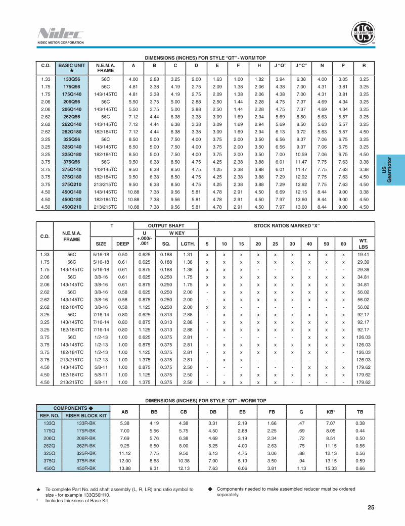
DIMENSIONS (INCHES) FOR STYLE “QT” - WORM TOP
C.D. BASIC UNITH
N.E.M.A. FRAME
A B C D E F H J “Q” J “C” N P R
1.33 133Q56 56C 4.00 2.88 3.25 2.00 1.63 1.00 1.82 3.94 6.38 4.00 3.05 3.25
1.75 175Q56 56C 4.81 3.38 4.19 2.75 2.09 1.38 2.06 4.38 7.00 4.31 3.81 3.25
1.75 175Q140 143/145TC 4.81 3.38 4.19 2.75 2.09 1.38 2.06 4.38 7.00 4.31 3.81 3.25
2.06 206Q56 56C 5.50 3.75 5.00 2.88 2.50 1.44 2.28 4.75 7.37 4.69 4.34 3.25
2.06 206Q140 143/145TC 5.50 3.75 5.00 2.88 2.50 1.44 2.28 4.75 7.37 4.69 4.34 3.25
2.62 262Q56 56C 7.12 4.44 6.38 3.38 3.09 1.69 2.94 5.69 8.50 5.63 5.57 3.25
2.62 262Q140 143/145TC 7.12 4.44 6.38 3.38 3.09 1.69 2.94 5.69 8.50 5.63 5.57 3.25
2.62 262Q180 182/184TC 7.12 4.44 6.38 3.38 3.09 1.69 2.94 6.13 9.72 5.63 5.57 4.50
3.25 325Q56 56C 8.50 5.00 7.50 4.00 3.75 2.00 3.50 6.56 9.37 7.06 6.75 3.25
3.25 325Q140 143/145TC 8.50 5.00 7.50 4.00 3.75 2.00 3.50 6.56 9.37 7.06 6.75 3.25
3.25 325Q180 182/184TC 8.50 5.00 7.50 4.00 3.75 2.00 3.50 7.00 10.59 7.06 6.75 4.50
3.75 375Q56 56C 9.50 6.38 8.50 4.75 4.25 2.38 3.88 6.01 11.47 7.75 7.63 3.38
3.75 375Q140 143/145TC 9.50 6.38 8.50 4.75 4.25 2.38 3.88 6.01 11.47 7.75 7.63 3.38
3.75 375Q180 182/184TC 9.50 6.38 8.50 4.75 4.25 2.38 3.88 7.29 12.92 7.75 7.63 4.50
3.75 375Q210 213/215TC 9.50 6.38 8.50 4.75 4.25 2.38 3.88 7.29 12.92 7.75 7.63 4.50
4.50 450Q140 143/145TC 10.88 7.38 9.56 5.81 4.78 2.91 4.50 6.69 12.15 8.44 9.00 3.38
4.50 450Q180 182/184TC 10.88 7.38 9.56 5.81 4.78 2.91 4.50 7.97 13.60 8.44 9.00 4.50
4.50 450Q210 213/215TC 10.88 7.38 9.56 5.81 4.78 2.91 4.50 7.97 13.60 8.44 9.00 4.50
C.D.N.E.M.A.FRAME
T OUTPUT SHAFT STOCK RATIOS MARKED “X”
U +.000/-
.001
W KEY
SIZE DEEP SQ. LGTH. 5 10 15 20 25 30 40 50 60WT. LBS
1.33 56C 5/16-18 0.50 0.625 0.188 1.31 x x x x x x x x x 19.41
1.75 56C 5/16-18 0.61 0.625 0.188 1.38 x x x x x x x x x 29.39
1.75 143/145TC 5/16-18 0.61 0.875 0.188 1.38 x x x - - - - - - 29.39
2.06 56C 3/8-16 0.61 0.625 0.250 1.75 x x x x x x x x x 34.81
2.06 143/145TC 3/8-16 0.61 0.875 0.250 1.75 x x x x x x x x x 34.81
2.62 56C 3/8-16 0.58 0.625 0.250 2.00 - x x x x x x x x 56.02
2.62 143/145TC 3/8-16 0.58 0.875 0.250 2.00 - x x x x x x x x 56.02
2.62 182/184TC 3/8-16 0.58 1.125 0.250 2.00 x x - - - - - - - 56.02
3.25 56C 7/16-14 0.80 0.625 0.313 2.88 - x x x x x x x x 92.17
3.25 143/145TC 7/16-14 0.80 0.875 0.313 2.88 - x x x x x x x x 92.17
3.25 182/184TC 7/16-14 0.80 1.125 0.313 2.88 - x x x x x x x x 92.17
3.75 56C 1/2-13 1.00 0.625 0.375 2.81 - - - - - - x x x 126.03
3.75 143/145TC 1/2-13 1.00 0.875 0.375 2.81 - x x x x x x x x 126.03
3.75 182/184TC 1/2-13 1.00 1.125 0.375 2.81 - x x x x x x x - 126.03
3.75 213/215TC 1/2-13 1.00 1.375 0.375 2.81 - x x - - - - - - 126.03
4.50 143/145TC 5/8-11 1.00 0.875 0.375 2.50 - - - - - - x x x 179.62
4.50 182/184TC 5/8-11 1.00 1.125 0.375 2.50 - - x x x x x x x 179.62
4.50 213/215TC 5/8-11 1.00 1.375 0.375 2.50 - x x x x - - - - 179.62
DIMENSIONS (INCHES) FOR STYLE “QT” - WORM TOP
COMPONENTS uAB BB CB DB EB FB G KB1 TB
REF. NO. RISER BLOCK KIT
133Q 133R-BK 5.38 4.19 4.38 3.31 2.19 1.66 .47 7.07 0.38
175Q 175R-BK 7.00 5.56 5.75 4.50 2.88 2.25 .69 8.05 0.44
206Q 206R-BK 7.69 5.76 6.38 4.69 3.19 2.34 .72 8.51 0.50
262Q 262R-BK 9.25 6.50 8.00 5.25 4.00 2.63 .75 11.15 0.56
325Q 325R-BK 11.12 7.75 9.50 6.13 4.75 3.06 .88 12.13 0.56
375Q 375R-BK 12.00 8.63 10.38 7.00 5.19 3.50 .94 13.15 0.59
450Q 450R-BK 13.88 9.31 12.13 7.63 6.06 3.81 1.13 15.33 0.66
H To complete Part No. add shaft assembly (L, R, LR) and ratio symbol to size - for example 133Q56H10.1 Includes thickness of Base Kit
u Components needed to make assembled reducer must be ordered separately.

26
NIDEC MOTOR CORPORATION
J
M
EC.D.
NCA
G
KP
B
T4 Holes D
F
VH
U Dia.W Key
Y
X Dia.Z Kw.
AA
Style UVL Vertical Low Base
Style UVJ Vertical "J" Base
Style UVH Vertical High Base
Assembly Drawing and Sample of Components
133UL10 133UR10 133ULR10 133VJ-BK 133VJ-BK 133VJ-BK
133UL10 133UR10 133ULR10 133VJ-BK 133VJ-BK 133VJ-BK
Note: If mounting a fan unit with input up, fan extends beyond "H" dimension.
Assembly Drawing and Sample of Components
133UL10 133UR10 133ULR10 133VL-BK 133VL-BK 133VL-BK
133UL10 133UR10 133ULR10 133VL-BK 133VL-BK 133VL-BK
Assembly Drawing and Sample of Components
133UL10 133UR10 133ULR10 133VH-BK 133VH-BK 133VH-BK
133UL10 133UR10 133ULR10 133VH-BK 133VH-BK 133VH-BK
AA
K
Y
G
F ND
BM
X Dia.Z Kw.
C.D.
T4 Holes
v
UDia.WKeyE J
CA
HP
AA
KB
X Dia.Z Kw.
Y
G
FD
BM
NE
CA
JU Dia.W Key
T4 Holes
HB
C.D.
VP
Worm Gear Reducers
27
US
G
earm
oto
r
NIDEC MOTOR CORPORATION
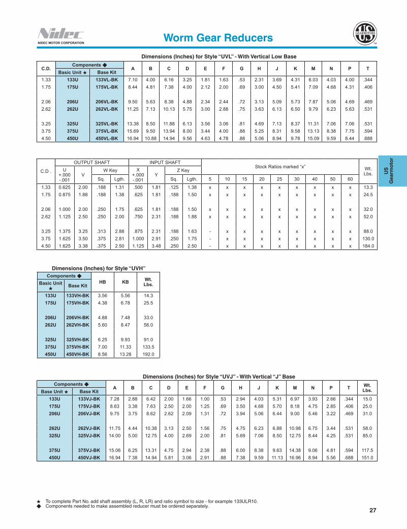
C.D.Components u
A B C D E F G H J K M N P TBasic Unit H Base Kit
1.33 133U 133VL-BK 7.10 4.00 6.16 3.25 1.81 1.63 .53 2.31 3.69 4.31 6.03 4.03 4.00 .3441.75 175U 175VL-BK 8.44 4.81 7.38 4.00 2.12 2.00 .69 3.00 4.50 5.41 7.09 4.68 4.31 .406
2.06 206U 206VL-BK 9.50 5.63 8.38 4.88 2.34 2.44 .72 3.13 5.09 5.73 7.87 5.06 4.69 .4692.62 262U 262VL-BK 11.25 7.13 10.13 5.75 3.00 2.88 .75 3.63 6.13 6.50 9.79 6.23 5.63 .531
3.25 325U 325VL-BK 13.38 8.50 11.88 6.13 3.56 3.06 .81 4.69 7.13 8.37 11.31 7.06 7.06 .5313.75 375U 375VL-BK 15.69 9.50 13.94 8.00 3.44 4.00 .88 5.25 8.31 9.58 13.13 8.38 7.75 .5944.50 450U 450VL-BK 16.94 10.88 14.94 9.56 4.63 4.78 .88 5.06 8.94 9.78 15.09 9.59 8.44 .688
C.D .
OUTPUT SHAFT INPUT SHAFTStock Ratios marked “x” Wt.
Lbs.U
+.000 -.001
V W Key X
+.000 -.001
YZ Key
Sq. Lgth. Sq. Lgth. 5 10 15 20 25 30 40 50 60
1.33 0.625 2.00 .188 1.31 .500 1.81 .125 1.38 x x x x x x x x x 13.31.75 0.875 1.88 .188 1.38 .625 1.81 .188 1.50 x x x x x x x x x 24.5
2.06 1.000 2.00 .250 1.75 .625 1.81 .188 1.50 x x x x x x x x x 32.02.62 1.125 2.50 .250 2.00 .750 2.31 .188 1.88 x x x x x x x x x 52.0
3.25 1.375 3.25 .313 2.88 .875 2.31 .188 1.63 - x x x x x x x x 88.03.75 1.625 3.50 .375 2.81 1.000 2.91 .250 1.75 - x x x x x x x x 130.04.50 1.625 3.38 .375 2.50 1.125 3.48 .250 2.50 - x x x x x x x x 184.0
Dimensions (Inches) for Style “UVL” - With Vertical Low Base
H To complete Part No. add shaft assembly (L, R, LR) and ratio symbol to size - for example 133ULR10.u Components needed to make assembled reducer must be ordered separately.
Worm Gear Reducers
Dimensions (Inches) for Style “UVH”Components u
HB KB Wt. Lbs.Basic Unit
HBase Kit
133U 133VH-BK 3.56 5.56 14.3175U 175VH-BK 4.38 6.78 25.5
206U 206VH-BK 4.88 7.48 33.0262U 262VH-BK 5.60 8.47 56.0
325U 325VH-BK 6.25 9.93 91.0375U 375VH-BK 7.00 11.33 133.5450U 450VH-BK 8.56 13.28 192.0
Dimensions (Inches) for Style “UVJ” - With Vertical “J” BaseComponents u
A B C D E F G H J K M N P T Wt. Lbs.Base Unit H Base Kit
133U 133VJ-BK 7.28 2.88 6.42 2.00 1.66 1.00 .53 2.94 4.03 5.31 6.97 3.93 2.66 .344 15.0175U 175VJ-BK 8.63 3.38 7.63 2.50 2.00 1.25 .69 3.50 4.68 5.70 8.18 4.75 2.85 .406 25.0206U 206VJ-BK 9.75 3.75 8.62 2.62 2.09 1.31 .72 3.94 5.06 6.44 9.00 5.46 3.22 .469 31.0
262U 262VJ-BK 11.75 4.44 10.38 3.13 2.50 1.56 .75 4.75 6.23 6.88 10.98 6.75 3.44 .531 58.0325U 325VJ-BK 14.00 5.00 12.75 4.00 2.69 2.00 .81 5.69 7.06 8.50 12.75 8.44 4.25 .531 85.0
375U 375VJ-BK 15.06 6.25 13.31 4.75 2.94 2.38 .88 6.00 8.38 9.63 14.38 9.06 4.81 .594 117.5450U 450VJ-BK 16.94 7.38 14.94 5.81 3.06 2.91 .88 7.38 9.59 11.13 16.96 8.94 5.56 .688 151.0
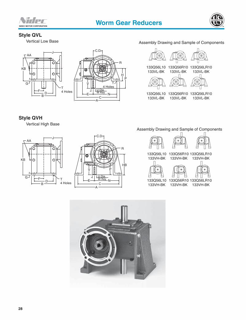
28
NIDEC MOTOR CORPORATION
Style QVL Vertical Low Base
Assembly Drawing and Sample of Components
133Q56L10 133Q56R10 133Q56LR10 133VH-BK 133VH-BK 133VH-BK
133Q56L10 133Q56R10 133Q56LR10 133VH-BK 133VH-BK 133VH-BK
Style QVH Vertical High Base
Assembly Drawing and Sample of Components
133Q56L10 133Q56R10 133Q56LR10 133VL-BK 133VL-BK 133VL-BK
133Q56L10 133Q56R10 133Q56LR10 133VL-BK 133VL-BK 133VL-BK
AAJ
KB
G
FD
B
T4 Holes
AC
E NU Dia.W Key
T4 Holes
P
V
H
R
C.D.
AAJ
KB
G FD
BT4 Holes
AC
NEU Dia.W Key
PV
HB
R
C.D.
Worm Gear Reducers

29
US
G
earm
oto
r
NIDEC MOTOR CORPORATION
Dimensions (Inches) for Style “QVL” - With Vertical Low Base
H To complete Part No. add shaft assembly (L, R, LR) and ratio symbol to size - for example 133Q56LR10.u Components needed to make assembled reducer must be ordered separately.
Worm Gear Reducers
C.D.Componentsu
N.E.M.A. Frame A B C D E F G H J K N PPart No.H Base Kit
1.33 133Q56 133VL-BK 56C 7.38 4.00 6.16 3.25 1.81 1.63 .53 2.31 3.94 4.31 3.69 4.001.75 175Q56 175VL-BK 56C 8.44 4.81 7.38 4.00 2.12 2.00 .69 3.00 4.38 5.41 4.50 4.311.75 175Q140 175VL-BK 143/145TC 8.44 4.81 7.38 4.00 2.12 2.00 .69 3.00 4.38 5.41 4.50 4.312.06 206Q56 206VL-BK 56C 9.50 5.63 8.38 4.88 2.34 2.44 .72 3.13 4.75 5.73 5.09 4.692.06 206Q140 206VL-BK 143/145TC 9.50 5.63 8.38 4.88 2.34 2.44 .72 3.13 4.75 5.73 5.09 4.692.62 262Q56 262VL-BK 56C 11.25 7.13 10.13 5.75 3.00 2.88 .75 3.63 5.69 6.50 6.13 5.632.62 262Q140 262VL-BK 143/145TC 11.25 7.13 10.13 5.75 3.00 2.88 .75 3.63 5.69 6.50 6.13 5.632.62 262Q180 262VL-BK 182/184TC 11.25 7.13 10.13 5.75 3.00 2.88 .75 3.63 5.69 6.50 6.13 5.633.25 325Q56 325VL-BK 56C 13.38 8.50 11.88 6.13 3.56 3.06 .81 4.69 6.56 8.37 7.13 7.063.25 325Q140 325VL-BK 143/145TC 13.38 8.50 11.88 6.13 3.56 3.06 .81 4.69 6.56 8.37 7.13 7.063.25 325Q180 325VL-BK 182/184TC 13.38 8.50 11.88 6.13 3.56 3.06 .81 4.69 7.00 8.37 7.13 7.063.75 375Q56 375VL-BK 56C 15.69 9.50 13.94 8.00 3.44 4.00 .88 5.25 6.01 9.58 8.31 7.753.75 375Q140 375VL-BK 143/145TC 15.69 9.50 13.94 8.00 3.44 4.00 .88 5.25 6.01 9.58 8.31 7.753.75 375Q180 375VL-BK 182/184TC 15.69 9.50 13.94 8.00 3.44 4.00 .88 5.25 7.29 9.58 8.31 7.753.75 375Q210 375VL-BK 213/215TC 15.69 9.50 13.94 8.00 3.44 4.00 .88 5.25 7.29 9.58 8.31 7.754.50 450Q140 450VL-BK 143/145TC 16.94 10.88 14.94 9.56 4.63 4.78 .88 5.06 6.69 9.78 8.94 8.444.50 450Q180 450VL-BK 182/184TC 16.94 10.88 14.94 9.56 4.63 4.78 .88 5.06 7.97 9.78 8.94 8.444.50 450Q210 450VL-BK 213/215TC 16.94 10.88 14.94 9.56 4.63 4.78 .88 5.06 7.97 9.78 8.94 8.44
C.D. NEMA. Frame R T
INPUTOUTPUT SHAFT
Stock Ratios marked “x” Wt Lbs.U
+.000 / -.001 VW Key
Bore Keyway Sq. Lgth. 5 10 15 20 25 30 40 50 601.33 56C 3.25 .344 .625 3/16 X 3/32 .625 2.00 .188 1.31 x x x x x x x x x 19.31.75 56C 3.25 .406 .625 3/16 X 3/32 .875 1.88 .188 1.38 x x x x x x x x x 31.51.75 143/145TC 3.25 .406 .875 3/16 X 3/32 .875 1.88 .188 1.38 x x x - - - - - - 31.52.06 56C 3.25 .469 .625 3/16 X 3/32 1.000 2.00 .250 1.75 x x x x x x x x x 39.02.06 143/145TC 3.25 .469 .875 3/16 X 3/32 1.000 2.00 .250 1.75 x x x x x - - - - 39.02.62 56C 3.25 .531 .625 3/16 X 3/32 1.125 2.50 .250 2.00 - x x x x x x x x 59.02.62 143/145TC 3.25 .531 .875 3/16 X 3/32 1.125 2.50 .250 2.00 - x x x x x x x x 59.02.62 182/184TC 4.50 .531 1.125 1/4 X 1/8 1.125 2.50 .250 2.00 x x - - - - - - - 59.03.25 56C 3.25 .531 .625 3/16 X 3/32 1.375 3.25 .313 2.88 - x x x x x x x x 103.03.25 143/145TC 3.25 .531 .875 3/16 X 3/32 1.375 3.25 .313 2.88 - x x x x x x x x 103.03.25 182/184TC 4.50 .531 1.125 1/4 X 1/8 1.375 3.25 .313 2.88 - x x x x x x x x 103.03.75 56C 3.38 .594 .625 3/16 X 3/32 1.625 3.50 .375 2.81 - - - - - - x x x 145.03.75 143/145TC 3.38 .594 .875 3/16 X 3/32 1.625 3.50 .375 2.81 - x x x x x x x x 145.03.75 182/184TC 4.50 .594 1.125 1/4 X 1/8 1.625 3.50 .375 2.81 - x x x x x x x - 145.03.75 213/215TC 4.50 .594 1.375 5/16 X 5/32 1.625 3.50 .375 2.81 - x x - - - - - - 145.04.50 143/145TC 3.38 .688 .875 3/16 X 3/32 1.625 3.38 .375 2.50 - - - - - - x x x 203.04.50 182/184TC 4.50 .688 1.125 1/4 X 1/8 1.625 3.38 .375 2.50 - - x x x x x x x 203.04.50 213/215TC 4.50 .688 1.375 5/16 X 5/32 1.625 3.38 .375 2.50 - x x x x - - - - 203.0
Dimensions (Inches) for Style “QVH” - With Vertical High Base
C.D.Components u NEMA.
Frame HB KB Wt. Lbs. C.D.
Components u NEMA. Frame HB KB Wt.
Lbs.Basic UnitH Base Kit Basic UnitH Base Kit1.33 133Q56 133VH-BK 56C 3.56 5.56 20.3 3.25 325Q56 325VH-BK 56C 6.25 9.93 106.0
3.25 325Q140 325VH-BK 143/145TC 6.25 9.93 106.01.75 175Q56 175VH-BK 56C 4.38 6.78 32.5 3.25 325Q180 325VH-BK 182/184TC 6.25 9.93 106.01.75 175Q140 175VH-BK 143/145TC 4.38 6.78 32.52.06 206Q56 206VH-BK 56C 4.88 7.48 40.0 3.75 375Q56 375VH-BK 56C 7.00 11.33 148.52.06 206Q140 206VH-BK 143/145TC 4.88 7.48 40.0 3.75 375Q180 375VH-BK 182/184TC 7.00 11.33 148.5
3.75 375Q210 375VH-BK 213/215TC 7.00 11.33 148.52.62 262Q56 262VH-BK 56C 5.60 8.47 63.02.62 262Q140 262VH-BK 143/145TC 5.60 8.47 63.0 4.50 450Q140 450VH-BK 143/145TC 8.56 13.28 211.02.62 262Q180 262VH-BK 182/184TC 5.60 8.47 63.0 4.50 450Q180 450VH-BK 182/184TC 8.56 13.28 211.0
4.50 450Q210 450VH-BK 213/215TC 8.56 13.28 211.0

30
NIDEC MOTOR CORPORATION
Style QVJ Vertical "J" Base
Assembly Drawing and Sample of Components
133Q56L10 133Q56R10 133Q56LR10 133VJ-BK 133VJ-BK 133VJ-BK
NOTE: If mounting a fan unit, fan extends beyond "H" dimension.
R
J
E
AAC.D.
NC
A
GV
FT4 Holes
PK
DB
H
U Dia.W Key
Worm Gear Reducers

31
US
G
earm
oto
r
NIDEC MOTOR CORPORATION
Dimensions (Inches) for Style “QVJ” - With Vertical “J” Base
H To complete Part No. add shaft assembly (L, R, LR) and ratio symbol to size - for example 133Q56LR10.u Components needed to make assembled reducer must be ordered separately.
Worm Gear Reducers
C.D.Components N.E.M.A.
Frame A B C D E F G H J K N PPart No. H Base Kit
1.33 133Q56 133VJ-BK 56C 7.28 2.88 6.42 2.00 1.66 1.00 .53 2.94 3.94 6.03 3.93 4.001.75 175Q56 175VJ-BK 56C 8.63 3.38 7.63 2.50 2.00 1.25 .69 3.50 4.38 6.75 4.75 4.311.75 175Q140 175VJ-BK 143/145TC 8.63 3.38 7.63 2.50 2.00 1.25 .69 3.50 4.38 6.75 4.75 4.312.06 206Q56 206VJ-BK 56C 9.75 3.75 8.62 2.62 2.09 1.31 .72 3.94 4.75 7.25 5.46 4.692.06 206Q140 206VJ-BK 143/145TC 9.75 3.75 8.62 2.62 2.09 1.31 .72 3.94 4.75 7.25 5.46 4.692.62 262Q56 262VJ-BK 56C 11.75 4.44 10.38 3.13 2.50 1.56 .75 4.75 5.69 8.50 6.75 5.632.62 262Q140 262VJ-BK 143/145TC 11.75 4.44 10.38 3.13 2.50 1.56 .75 4.75 5.69 8.50 6.75 5.632.62 262Q180 262VJ-BK 182/184TC 11.75 4.44 10.38 3.13 2.50 1.56 .75 4.75 6.13 8.50 6.75 5.633.25 325Q56 325VJ-BK 56C 14.00 5.00 12.75 4.00 2.69 2.00 .81 5.69 6.56 10.60 8.44 7.063.25 325Q140 325VJ-BK 143/145TC 14.00 5.00 12.75 4.00 2.69 2.00 .81 5.69 6.56 10.60 8.44 7.063.25 325Q180 325VJ-BK 182/184TC 14.00 5.00 12.75 4.00 2.69 2.00 .81 5.69 7.00 10.60 8.44 7.063.75 375Q56 375VJ-BK 56C 15.06 6.25 13.31 4.75 2.94 2.38 .88 6.00 6.01 11.88 9.06 7.753.75 375Q140 375VJ-BK 143/145TC 15.06 6.25 13.31 4.75 2.94 2.38 .88 6.00 6.01 11.88 9.06 7.753.75 375Q180 375VJ-BK 182/184TC 15.06 6.25 13.31 4.75 2.94 2.38 .88 6.00 7.29 11.88 9.06 7.753.75 375Q210 375VJ-BK 213/215TC 15.06 6.25 13.31 4.75 2.94 2.38 .88 6.00 7.29 11.88 9.06 7.754.50 450Q140 450VJ-BK 143/145TC 16.94 7.38 14.94 5.81 3.06 2.91 .88 7.38 6.69 13.16 10.50 8.444.50 450Q180 450VJ-BK 182/184TC 16.94 7.38 14.94 5.81 3.06 2.91 .88 7.38 7.97 13.16 10.50 8.444.50 450Q210 450VJ-BK 213/215TC 16.94 7.38 14.94 5.81 3.06 2.91 .88 7.38 7.97 13.16 10.50 8.44
C D N.E.M.A. Frame R T
INPUTOUTPUT SHAFT
Stock Ratios marked xWt. Lbs.
U +000 -.001
VW K ey
Bore Keyway Sq. Lgth. 5 10 15 20 25 30 40 50 60
1.33 56C 3.25 .344 .625 3/16 X 3/32 .625 2.00 .188 1.31 x x x x x x x - x 18.0
1.75 56C 3.25 .406 .625 3/16 X 3/32 .875 1.88 .188 1.38 x x x x x x x x x 29.0
1.75 143/145TC 3.25 .406 .875 3/16 X 3/32 .875 1.88 .188 1.38 x x x - - - - - - 29.0
2.06 56C 3.25 .469 .625 3/16 X 3/32 1.000 2.00 .250 1.75 x x x x x x x x x 35.0
2.06 143/145TC 3.25 .469 .875 3/16 X 3/32 1.000 2.00 .250 1.75 x x x x x - - - - 35.0
2.62 56C 3.25 .531 .625 3/16 X 3/32 1.125 2.50 .250 2.00 - x x x x x x x x 54.0
2.62 143/145TC 3.25 .531 .875 3/16 X 3/32 1.125 2.50 .250 2.00 - x x x x x x x x 54.0
2.62 182/184TC 4.50 .531 1.125 1/4 X 1/8 1.125 2.50 .250 2.00 x x - - - - - - - 54.0
3.25 56C 3.25 .531 .625 3/16 X 3/32 1.375 3.25 .313 2.88 - x x x x x x x x 93.0
3.25 143/145TC 3.25 .531 .875 3/16 X 3/32 1.375 3.25 .313 2.88 - x x x x x x x x 93.0
3.25 182/184TC 4.50 .531 1.125 1/4 X 1/8 1.375 3.25 .313 2.88 - x x x x x x x x 93.0
3.75 56C 3.38 .594 .625 3/16 X 3/32 1.625 3.50 .375 2.81 - - - - - - x x x 128.5
3.75 143/145TC 3.38 .594 .875 3/16 X 3/32 1.625 3.50 .375 2.81 - x x x x x x x x 128.5
3.75 182/184TC 4.50 .594 1.125 1/4 X 1/8 1.625 3.50 .375 2.81 - x x x x x x x - 128.5
3.75 213/215TC 4.50 .594 1.375 5/16 X 5/32 1.625 3.50 .375 2.81 - x x - - - - - - 128.5
4.50 143/145TC 3.38 .688 .875 3/16 X 3/32 1.625 3.38 .375 2.50 - - - - - - x x x 181.0
4.50 182/184TC 4.50 .688 1.125 1/4 X 1/8 1.625 3.38 .375 2.50 - - x x x x x x x 181.0
4.50 213/215TC 4.50 .688 1.375 5/16 X 5/32 1.625 3.38 .375 2.50 - x x x x - - - - 181.0

32
NIDEC MOTOR CORPORATION
Style CVL Vertical Low Base
Style CVJ Vertical "J" Base
Assembly Drawing and Sample of Components
133UL10 133UR10 133ULR10 133VJ-BK 133VJ-BK 133VJ-BK 133MAK56 133MAK56 133MAK56
Note: If mounting a fan unit, fan extends beyond "H" dimension.
Style CVH Vertical High Base
Assembly Drawing and Sample of Components
133UL10 133UR10 133ULR10 133VL-BK 133VL-BK 133VL-BK 133MAK56 133MAK56 133MAK56
133UL10 133UR10 133ULR10 133VL-BK 133VL-BK 133VL-BK 133MAK56 133MAK56 133MAK56
Assembly Drawing and Sample of Components
133UL10 133UR10 133ULR10 133VH-BK 133VH-BK 133VH-BK 133MAK56 133MAK56 133MAK56
133UL10 133UR10 133ULR10 133VH-BK 133VH-BK 133VH-BK 133MAK56 133MAK56 133MAK56
AAJ
K
G
FD
B E
AC
NU Dia.W Key
V T4 Holes
HP
R
C.D.
AAJ
KB
G FD
BT4 Holes
E NC
A
U Dia.W Key
V
HB
R
C.D.
P
R
J
AAC.D.
NC
A
E
G
KP
V
T4 Holes B
DF
H
U Dia.W Key
Worm Gear Reducers

33
US
G
earm
oto
r
NIDEC MOTOR CORPORATION
Dimensions (Inches) for Style “CVL” - With Vertical Low Base
H To complete Part No. add shaft assembly (L, R, LR) and ratio symbol to size - for example 133ULR10.u Components needed to make assembled reducer must be ordered separately.
Worm Gear Reducers
C.D.Compnents u
A B C D E F G H K N P TBase Unit. H Adapter Kit Base Kit
1.33 133U
SeeAdapter KitTable Below
133VL-BK 7.10 4.00 6.16 3.25 1.81 1.63 .53 2.31 4.31 3.69 4.00 .3441.75 175U 175VL-BK 8.44 4.81 7.38 4.00 2.12 2.00 .69 3.00 5.41 4.50 4.31 .4062.06 206U 206VL-BK 9.50 5.63 8.38 4.88 2.34 2.44 .72 3.13 5.73 5.09 4.69 .4692.62 262U 262VL-BK 11.25 7.13 10.13 5.75 3.00 2.88 .75 3.63 6.50 6.13 5.63 .5313.25 325U 325VL-BK 13.38 8.50 11.88 6.13 3.56 3.06 .81 4.69 8.37 7.13 7.06 .5313.75 375U 375VL-BK 15.69 9.50 13.94 8.00 3.44 4.00 .88 5.25 9.58 8.31 7.75 .5944.50 450U 450VL-BK 16.94 10.88 14.94 9.56 4.63 4.78 .88 5.06 9.78 10.56 8.44 .688
C.D.
OUTPUT SHAFTStock Ratios marked “x Wt.
Lbs.U +.000 -.001
VW Key
Sq. Lgth. 5 10 15 20 25 30 40 50 601.33 .625 2.00 .188 1.31 x x x x x x x x x 20.31.75 .875 1.88 .188 1.38 x x x x x x x x x 31.52.06 1.000 2.00 .250 1.75 x x x x x x x x x 39.02.62 1.125 2.50 .250 2.00 x x x x x x x x x 63.03.25 1.375 3.25 .313 2.88 - x x x x x x x x 99.03.75 1.625 3.50 .375 2.81 - x x x x x x x x 142.54.50 1.625 3.38 .375 2.50 - x x x x x x x x 200.0
Dimensions (Inches) for Style “CVH”Components u
HB KB Wt. Lbs.Base Unit. H Adapter Kit Base Kit
133U
SeeAdapter KitTable Below
133VH-BK 3.56 5.56 21.3175U 175VH-BK 4.38 6.78 32.5206U 206VH-BK 4.88 7.48 40.0262U 262VH-BK 5.60 8.47 67.0325U 325VH-BK 6.25 9.93 102.0375U 375VH-BK 7.00 11.33 146.0450U 450VH-BK 8.56 13.28 208.0
Dimensions (Inches) for Style “CVJ” - Vertical “J” BaseComponents u
A B C D E F G H K N P T Wt. Lbs.Base Unit H Adapter Kit Base Kit
133U
See Adapter Kit Table Below
133VJ-BK 7.28 2.88 6.42 2.00 1.66 1.00 .53 2.94 6.03 3.93 4.00 .344 19.0175U 175VJ-BK 8.63 3.38 7.63 2.50 2.00 1.25 .69 3.50 6.75 4.75 4.31 .406 29.0206U 206VJ-BK 9.75 3.75 8.62 2.62 2.09 1.31 .72 3.94 7.25 5.46 4.69 .469 35.0262U 262VJ-BK 11.75 4.44 10.38 3.13 2.50 1.56 .75 4.75 8.50 6.75 5.63 .531 58.0325U 325VJ-BK 14.00 5.00 12.75 4.00 2.69 2.00 .81 5.69 10.60 8.44 7.06 .531 89.0375U 375VJ-BK 15.06 6.25 13.31 4.75 2.94 2.38 .88 6.00 11.88 9.06 7.75 .594 126.0450U 450VJ-BK 16.94 7.38 14.94 5.81 3.06 2.91 .88 7.38 13.16 8.94 8.44 .688 178.0
N.E.M.A. Frame Adapter Kits and Dimensions
C.D.
56C 143/145TC 182/184TC 213/215TCInput: .625
Kw.: 3/16 x 3/32Input: .875
Kw.: 3/16 x 3/32Input: 1.125
KW.: 1/4 x 1/8Input: 1.375
Kw.: 5/16 x 5/32Adapter Kit No. J R Adapter Kit No. J R Adapter Kit No. J R Adapter Kit No. J R
1.33 133MAK56 6.38 3.25 133MAK140 6.38 3.25 - - - - - -1.75 154-206MAK56 7.00 3.25 154-206MAK140 7.00 3.25 - - - - - -2.06 154-206MAK56 7.37 3.25 154-206MAK140 7.37 3.25 - - - - - -2.62 262MAK56 8.50 3.25 262MAK140 8.50 3.25 262MAK180 9.72 4.50 - - -3.25 300-325MAK56 9.37 3.25 300-325MAK140 9.37 3.25 300-325MAK180 10.59 4.50 325MAK210 10.59 4.503.75 375MAK56 11.47 3.38 375MAK140 11.47 3.38 375MAK180 12.92 4.50 375MAK210 12.92 4.504.50 450MAK140 12.15 3.38 450MAK180 13.60 4.50 450MAK210 13.60 4.50
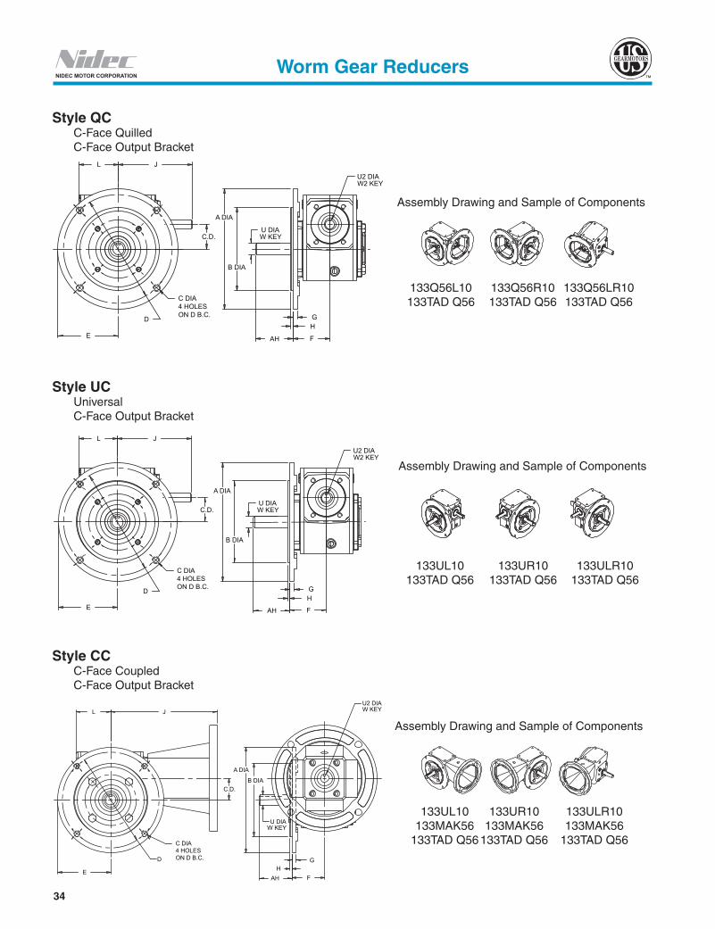
34
NIDEC MOTOR CORPORATION
Style UC Universal C-Face Output Bracket
Style QC C-Face Quilled C-Face Output Bracket
Worm Gear Reducers
Style CC C-Face Coupled C-Face Output Bracket
Assembly Drawing and Sample of Components
133UL10 133UR10 133ULR10 133MAK56 133MAK56 133MAK56 133TAD Q56 133TAD Q56 133TAD Q56
W KEY
G H
F AH
U2 DIA W2 KEY
A DIA
B DIA
U DIA
E
L J
C.D.
C DIA4 HOLESON D B.C.
D
W KEY
G H
F AH
U2 DIA W2 KEY
A DIA
B DIA
U DIA
E
L J
C.D.
C DIA4 HOLESON D B.C.
D
L J
C.D.
D
E AH
G H
F
A DIA
B DIA
U DIAW KEY
U2 DIAW KEY
C DIA4 HOLESON D B.C.
Assembly Drawing and Sample of Components
133Q56L10 133Q56R10 133Q56LR10 133TAD Q56 133TAD Q56 133TAD Q56
Assembly Drawing and Sample of Components
133UL10 133UR10 133ULR10 133TAD Q56 133TAD Q56 133TAD Q56
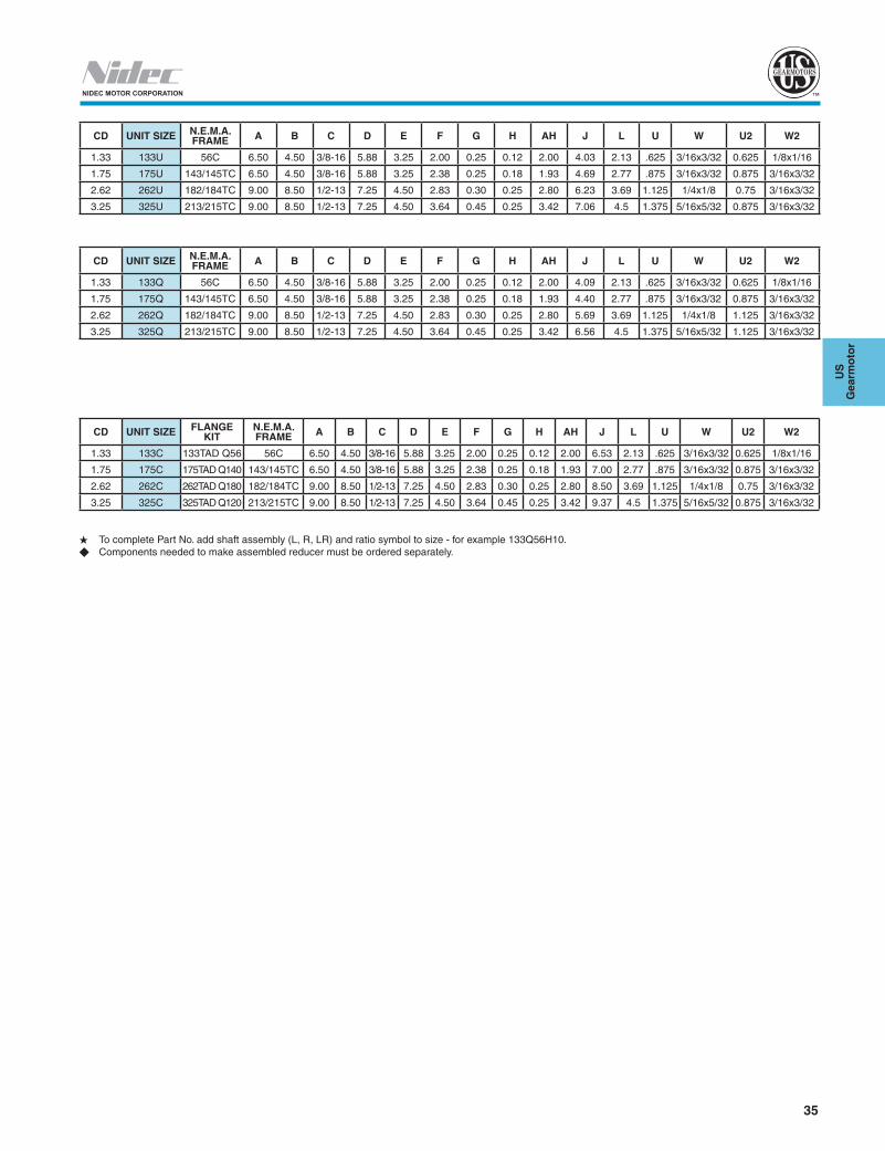
35
US
G
earm
oto
r
NIDEC MOTOR CORPORATION
CD UNIT SIZE N.E.M.A. FRAME A B C D E F G H AH J L U W U2 W2
1.33 133U 56C 6.50 4.50 3/8-16 5.88 3.25 2.00 0.25 0.12 2.00 4.03 2.13 .625 3/16x3/32 0.625 1/8x1/16
1.75 175U 143/145TC 6.50 4.50 3/8-16 5.88 3.25 2.38 0.25 0.18 1.93 4.69 2.77 .875 3/16x3/32 0.875 3/16x3/32
2.62 262U 182/184TC 9.00 8.50 1/2-13 7.25 4.50 2.83 0.30 0.25 2.80 6.23 3.69 1.125 1/4x1/8 0.75 3/16x3/32
3.25 325U 213/215TC 9.00 8.50 1/2-13 7.25 4.50 3.64 0.45 0.25 3.42 7.06 4.5 1.375 5/16x5/32 0.875 3/16x3/32
CD UNIT SIZE N.E.M.A. FRAME A B C D E F G H AH J L U W U2 W2
1.33 133Q 56C 6.50 4.50 3/8-16 5.88 3.25 2.00 0.25 0.12 2.00 4.09 2.13 .625 3/16x3/32 0.625 1/8x1/16
1.75 175Q 143/145TC 6.50 4.50 3/8-16 5.88 3.25 2.38 0.25 0.18 1.93 4.40 2.77 .875 3/16x3/32 0.875 3/16x3/32
2.62 262Q 182/184TC 9.00 8.50 1/2-13 7.25 4.50 2.83 0.30 0.25 2.80 5.69 3.69 1.125 1/4x1/8 1.125 3/16x3/32
3.25 325Q 213/215TC 9.00 8.50 1/2-13 7.25 4.50 3.64 0.45 0.25 3.42 6.56 4.5 1.375 5/16x5/32 1.125 3/16x3/32
H To complete Part No. add shaft assembly (L, R, LR) and ratio symbol to size - for example 133Q56H10.u Components needed to make assembled reducer must be ordered separately.
CD UNIT SIZE FLANGE KIT
N.E.M.A. FRAME A B C D E F G H AH J L U W U2 W2
1.33 133C 133TAD Q56 56C 6.50 4.50 3/8-16 5.88 3.25 2.00 0.25 0.12 2.00 6.53 2.13 .625 3/16x3/32 0.625 1/8x1/16
1.75 175C 175TAD Q140 143/145TC 6.50 4.50 3/8-16 5.88 3.25 2.38 0.25 0.18 1.93 7.00 2.77 .875 3/16x3/32 0.875 3/16x3/32
2.62 262C 262TAD Q180 182/184TC 9.00 8.50 1/2-13 7.25 4.50 2.83 0.30 0.25 2.80 8.50 3.69 1.125 1/4x1/8 0.75 3/16x3/32
3.25 325C 325TAD Q120 213/215TC 9.00 8.50 1/2-13 7.25 4.50 3.64 0.45 0.25 3.42 9.37 4.5 1.375 5/16x5/32 0.875 3/16x3/32
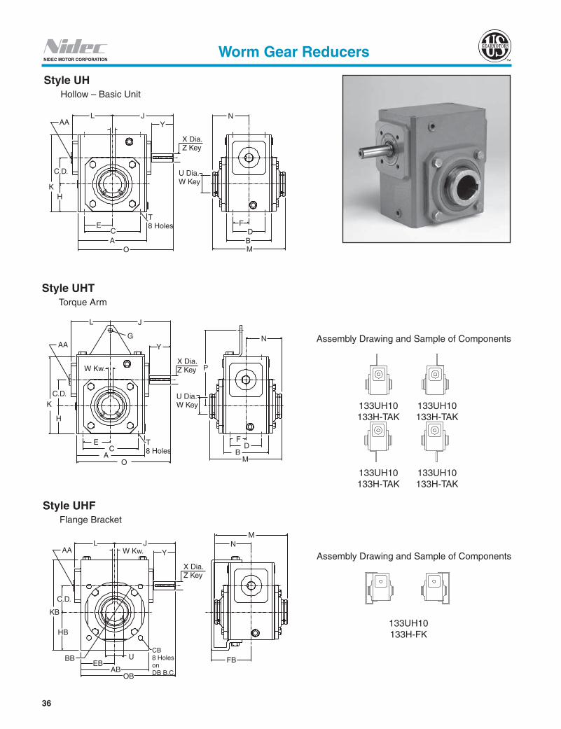
36
NIDEC MOTOR CORPORATION
Style UHT Torque Arm
Style UHF Flange Bracket
Style UH Hollow – Basic Unit
Assembly Drawing and Sample of Components
133UH10 133H-FK
Assembly Drawing and Sample of Components
133UH10 133UH10 133H-TAK 133H-TAK
133UH10 133UH10 133H-TAK 133H-TAK
AAL J
Y
K
C.D.
H
ECA
O
T8 Holes
MBD
F
U Dia.W Key
N
X Dia.Z Key
AA
C.D.
G
W Kw.
K
H
EC
AO
T8 Holes
U Dia.W Key
X Dia.Z Key
Y
P
N
FD
BM
L J
AAL J
W Kw.
C.D.
KB
Y
HB
BBEB
ABOB
CB8 HolesonDB B.C.
FB
X Dia.Z Key
NM
U
Worm Gear Reducers

37
US
G
earm
oto
r
NIDEC MOTOR CORPORATION
Dimensions (Inches) for Style “UH”
Dimensions (Inches) for Style “UHT” - With Torque Arm
Dimensions (Inches) for Style “UHF” - With Flange
H To complete Part No. add ratio symbol to size - for example 133UH10.u Components needed to make assembled reducer must be ordered separately.
Worm Gear Reducers
C.D. Basic Unit H A B C D E F H J K L M N O1.33 133UH 4.00 2.88 3.25 2.00 1.63 1.00 1.72 4.03 4.66 2.12 5.31 2.66 6.031.75 175UH 4.81 3.38 4.19 2.75 2.09 1.38 2.06 4.68 5.75 2.75 5.70 2.85 7.092.06 206UH 5.50 3.75 5.00 2.88 2.50 1.44 2.28 5.06 6.38 3.00 6.44 3.22 7.73
2.62 262UH 7.12 4.44 6.38 3.38 3.19 1.69 2.94 6.23 8.00 3.69 6.88 3.44 9.793.25 325UH 8.50 5.00 7.50 4.00 3.75 2.00 3.50 7.06 9.38 4.50 8.50 4.25 11.31
3.75 375UH 9.50 6.38 8.50 4.75 4.25 2.38 3.88 8.38 10.44 5.74 9.63 4.81 13.134.50 450UH 10.88 7.38 9.56 5.81 4.78 2.91 4.50 9.59 11.94 6.42 11.13 5.56 15.09
C.D.T
OUTPUT BORE INPUT SHAFTStock Ratios marked “x” Wt.
Lbs.U
+.0015 -.0000
W KeywayX
+.000 -.001
YZ Key
Size Deep Sq. Lgth. 5 10 15 20 25 30 40 50 60
1.33 5/16-18 .50 .6250 3/16 x 3/32 .500 1.81 .125 1.38 x x x x x x x x x 14.01.75 5/16-18 .61 1.0000 1/4 x 1/8 .625 1.81 .188 1.50 x x x x x x x x x 23.02.06 3/8-16 .61 1.4375 3/8 x 1/8 .625 1.81 .188 1.50 x x x x x x x x x 28.0
2.62 3/8-16 .58 1.9375 1/2 x 1/8 .750 2.31 .188 1.88 x x x x x x x x x 54.03.25 7/16-14 .80 2.1875 1/2 x 3/16 .875 2.31 .188 1.63 - x x x x x x x x 79.0
3.75 1/2-13 1.00 2.4375 5/8 x 3/16 1.000 2.91 .250 1.75 - x x x x x x x x 109.04.50 5/8-11 1.00 2.9375 3/4 x 1/4 1.125 3.48 .250 2.50 - x x x x x x x x 140.0
Components uG P Wt.
Lbs.Basic Unit H Torque Arm Kit
133UH 133H-TAK .53 4.16 14.6175UH 175H-TAK .53 5.06 23.9206UH 206H-TAK .53 6.07 29.0
262UH 262H-TAK .53 7.44 55.4325UH 325H-TAK .53 9.06 81.0
375UH 375H-TAK .53 9.56 111.6450UH 450H-TAK .81 10.94 143.4
Components u AB BB CB DB EB FB HB J KB L M N OB Wt. Lbs.Basic Unit H Flange Kit
133UH 133H-FK 4.25 3.63 .344 5.000 2.13 3.00 2.44 4.03 5.57 2.12 5.31 2.66 6.16 16.7175UH 175H-FK 4.81 4.06 .344 5.875 2.41 3.50 2.78 4.68 6.66 2.75 5.70 2.85 7.09 26.4206UH 206H-FK 5.75 4.50 .406 6.500 2.88 3.75 3.14 5.06 7.43 3.00 6.44 3.22 7.94 32.6
262UH 262H-FK 7.18 6.00 .406 8.000 3.59 4.06 3.94 6.23 9.25 3.69 6.88 3.44 9.82 62.4325UH 325H-FK 8.50 7.00 .563 10.000 4.25 5.25 4.75 7.06 10.89 4.50 8.50 4.25 11.31 90.9
375UH 375H-FK 9.54 8.00 .563 11.500 4.77 5.46 5.04 8.38 11.85 5.74 9.63 4.81 13.13 122.3450UH 450H-FK 10.88 9.00 .563 11.500 5.44 6.88 5.34 9.59 13.10 6.42 11.13 5.56 15.09 161.8
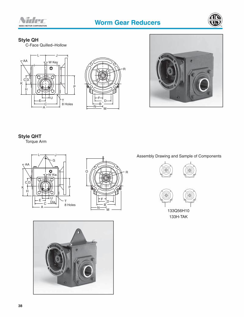
38
NIDEC MOTOR CORPORATION
Style QHT Torque Arm
Style QH C-Face Quilled–Hollow
Assembly Drawing and Sample of Components
133Q56H10
133H-TAK
AA
L J
C.D.K
H
EC
A
T8 Holes
U
P
W Key
R
FD
NM
B
AA
L J
G
K
C.D.
P
T8 Holes
UDia.E
CA
W Kw.
F
NM
R
D
O
B
H
Worm Gear Reducers

39
US
G
earm
oto
r
NIDEC MOTOR CORPORATION
Dimensions (Inches) for Style “QH”
H To complete Part No. add ratio symbol to size - for example 133Q56H10.u Components needed to make assembled reducer must be ordered separately.
Worm Gear Reducers
C.D. Basic Unit H N.E.M.A. Frame A B C D E F H J K L M N P R1.33 133Q56H 56C 4.00 2.88 3.25 2.00 1.63 1.00 1.72 3.94 4.66 2.12 5.31 2.66 3.05 3.251.75 175Q56H 56C 4.81 3.38 4.19 2.75 2.09 1.38 2.06 4.38 5.75 2.75 5.70 2.85 3.81 3.251.75 175Q140H 143/145TC 4.81 3.38 4.19 2.75 2.09 1.38 2.06 4.38 5.75 2.75 5.70 2.85 3.81 3.252.06 206Q56H 56C 5.50 3.75 5.00 2.88 2.50 1.44 2.28 4.75 6.38 3.00 6.44 3.22 4.34 3.252.06 206Q140H 143/145TC 5.50 3.75 5.00 2.88 2.50 1.44 2.28 4.75 6.38 3.00 6.44 3.22 4.34 3.252.62 262Q56H 56C 7.12 4.44 6.38 3.38 3.19 1.69 2.94 5.69 8.00 3.69 6.88 3.44 5.57 3.252.62 262Q140H 143/145TC 7.12 4.44 6.38 3.38 3.19 1.69 2.94 5.69 8.00 3.69 6.88 3.44 5.57 3.252.62 262Q180H 182/184TC 7.12 4.44 6.38 3.38 3.19 1.69 2.94 6.13 8.00 3.69 6.88 3.44 5.57 4.503.25 325Q56H 56C 8.50 5.00 7.50 4.00 3.75 2.00 3.50 6.56 9.38 4.50 8.50 4.25 6.75 3.253.25 325Q140H 143/145TC 8.50 5.00 7.50 4.00 3.75 2.00 3.50 6.56 9.38 4.50 8.50 4.25 6.75 3.253.25 325Q180H 182/184TC 8.50 5.00 7.50 4.00 3.75 2.00 3.50 7.00 9.38 4.50 8.50 4.25 6.75 4.503.75 375Q56H 56C 9.50 6.38 8.50 4.75 4.25 2.38 3.88 6.01 10.44 4.93 9.63 4.81 7.63 3.383.75 375Q140H 143/145TC 9.50 6.38 8.50 4.75 4.25 2.38 3.88 6.01 10.44 4.93 9.63 4.81 7.63 3.383.75 375Q180H 182/184TC 9.50 6.38 8.50 4.75 4.25 2.38 3.88 7.29 10.44 4.93 9.63 4.81 7.63 4.503.75 375Q210H 213/215TC 9.50 6.38 8.50 4.75 4.25 2.38 3.88 7.29 10.44 4.93 9.63 4.81 7.63 4.504.50 450Q140H 143/145TC 10.88 7.38 9.56 5.81 4.78 2.91 4.50 6.69 11.94 6.42 11.13 5.56 9.00 3.384.50 450Q180H 182/184TC 10.88 7.38 9.56 5.81 4.78 2.91 4.50 7.97 11.94 6.42 11.31 5.66 9.00 4.504.50 450Q210H 213/215TC 10.88 7.38 9.56 5.81 4.78 2.91 4.50 7.97 11.94 6.42 11.31 5.66 9.00 4.50
C.D. N.E.M.A. Frame
T InputOUTPUT
Stock Ratios marked "x" Wt. Lbs.U
+.0015 -.0000
W KeywaySize Deep Bore Keyway 5 10 15 20 25 30 40 50 60
1.33 56C 5/16-18 .50 .625 3/16 x 3/32 .6250 3/16 x 3/32 x x x x x x x x x 17.01.75 56C 5/16-18 .61 .625 3/16 x 3/32 1.0000 1/4 x 1/8 x x x x x x x x x 25.01.75 143/145TC 5/16-18 .61 .875 3/16 x 3/32 1.0000 1/4 x 1/8 x x x - - - - - - 25.02.06 56C 3/8-16 .61 .625 3/16 x 3/32 1.4375 3/8 x 1/8 x x x x x x x x x 33.02.06 143/145TC 3/8-16 .61 .875 3/16 x 3/32 1.4375 3/8 x 1/8 x x x x x - - - - 33.02.62 56C 3/8-16 .58 .625 3/16 x 3/32 1.9375 1/2 x 1/8 - x x x x x x x x 57.02.62 143/145TC 3/8-16 .58 .875 3/16 x 3/32 1.9375 1/2 x 1/8 - x x x x x x x x 57.02.62 182/184TC 3/8-16 .58 1.125 1/4 x 1/8 1.9375 1/2 x 1/8 x x - - - - - - - 57.03.25 56C 7/16-14 .80 .625 3/16 x 3/32 2.1875 1/2 x 3/16 - x x x x x x x x 83.03.25 143/145TC 7/16-14 .80 .875 3/16 x 3/32 2.1875 1/2 x 3/16 - x x x x x x x x 83.03.25 182/184TC 7/16-14 .80 1.125 1/4 x 1/8 2.1875 1/2 x 3/16 - x x x x x x x x 83.03.75 56C 1/2-13 1.00 .625 3/16 x 3/32 2.4375 5/8 x 3/16 - - - - - - x x x 116.03.75 143/145TC 1/2-13 1.00 .875 3/16 x 3/32 2.4375 5/8 x 3/16 - x x x x x x x x 116.03.75 182/184TC 1/2-13 1.00 1.125 1/4 x 1/8 2.4375 5/8 x 3/16 - x x x x x x x - 116.03.75 213/215TC 1/2-13 1.00 1.375 3/16 x 3/32 2.4375 5/8 x 3/16 - x x - - - - - - 116.04.50 143/145TC 5/8-11 1.00 .875 3/16 x 3/32 2.9375 3/4 x 1/4 - - - - - - x x x 150.04.50 182/184TC 5/8-11 1.00 1.125 1/4 x 1/8 2.9375 3/4 x 1/4 - - x x x x x x x 150.04.50 213/215TC 5/8-11 1.00 1.375 5/16 x 5/32 2.9375 3/4 x 1/4 - x x x x - - - - 150.0
Dimensions (Inches) for Style “QHT”Components u
G O Wt. Lbs.Ref. No. Torque Arm Kit
133QH 133H-TAK .53 4.16 17.6175QH 175H-TAK .53 5.06 25.9206QH 206H-TAK .53 6.07 34.0262QH 262H-TAK .53 7.44 58.4325QH 325H-TAK .53 9.06 85.0375QH 375H-TAK .53 9.56 118.6450QH 450H-TAK .81 10.94 153.4

40
NIDEC MOTOR CORPORATION
Style UHCF Universal Cast Iron Output Flange Hollow
Style QHCF C-Face Quilled Cast Iron Output Flange Hollow
Worm Gear Reducers
Style CHCF C-Face Coupled Cast Iron Output Flange Hollow
Assembly Drawing and Sample of Components
133UH10 133UH10 133MAK56 133MAK56 133H-SK 133H-SK
C DIA.4 HOLESON D B.C.
K
H
U DIAW KEY
E
A
F
CD
N
G
L J R
C DIA.4 HOLESON D B.C.
A E
U DIA.W KEY
N F
G
K
H
L J
CD
L J
K
H
F
CD
R
N
GC DIA.4 HOLESON D B.C.
C DIAW KEY E
A
Assembly Drawing and Sample of Components
133Q56H10 133Q56H10 133H-SK 133H-SK
Assembly Drawing and Sample of Components
133UH10 133UH10 133H-SK 133H-SK
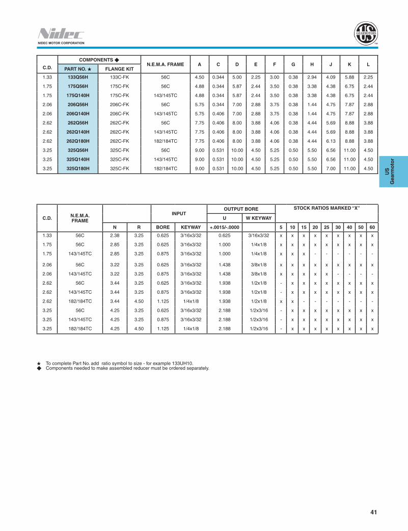
41
US
G
earm
oto
r
NIDEC MOTOR CORPORATION
C.D.
COMPONENTS uN.E.M.A. FRAME A C D E F G H J K L
PART NO. H FLANGE KIT
1.33 133Q56H 133C-FK 56C 4.50 0.344 5.00 2.25 3.00 0.38 2.94 4.09 5.88 2.25
1.75 175Q56H 175C-FK 56C 4.88 0.344 5.87 2.44 3.50 0.38 3.38 4.38 6.75 2.44
1.75 175Q140H 175C-FK 143/145TC 4.88 0.344 5.87 2.44 3.50 0.38 3.38 4.38 6.75 2.44
2.06 206Q56H 206C-FK 56C 5.75 0.344 7.00 2.88 3.75 0.38 1.44 4.75 7.87 2.88
2.06 206Q140H 206C-FK 143/145TC 5.75 0.406 7.00 2.88 3.75 0.38 1.44 4.75 7.87 2.88
2.62 262Q56H 262C-FK 56C 7.75 0.406 8.00 3.88 4.06 0.38 4.44 5.69 8.88 3.88
2.62 262Q140H 262C-FK 143/145TC 7.75 0.406 8.00 3.88 4.06 0.38 4.44 5.69 8.88 3.88
2.62 262Q180H 262C-FK 182/184TC 7.75 0.406 8.00 3.88 4.06 0.38 4.44 6.13 8.88 3.88
3.25 325Q56H 325C-FK 56C 9.00 0.531 10.00 4.50 5.25 0.50 5.50 6.56 11.00 4.50
3.25 325Q140H 325C-FK 143/145TC 9.00 0.531 10.00 4.50 5.25 0.50 5.50 6.56 11.00 4.50
3.25 325Q180H 325C-FK 182/184TC 9.00 0.531 10.00 4.50 5.25 0.50 5.50 7.00 11.00 4.50
C.D. N.E.M.A. FRAME
INPUTOUTPUT BORE STOCK RATIOS MARKED “X”
U W KEYWAY
N R BORE KEYWAY +.0015/-.0000 5 10 15 20 25 30 40 50 60
1.33 56C 2.38 3.25 0.625 3/16x3/32 0.625 3/16x3/32 x x x x x x x x x
1.75 56C 2.85 3.25 0.625 3/16x3/32 1.000 1/4x1/8 x x x x x x x x x
1.75 143/145TC 2.85 3.25 0.875 3/16x3/32 1.000 1/4x1/8 x x x - - - - - -
2.06 56C 3.22 3.25 0.625 3/16x3/32 1.438 3/8x1/8 x x x x x x x x x
2.06 143/145TC 3.22 3.25 0.875 3/16x3/32 1.438 3/8x1/8 x x x x x - - - -
2.62 56C 3.44 3.25 0.625 3/16x3/32 1.938 1/2x1/8 - x x x x x x x x
2.62 143/145TC 3.44 3.25 0.875 3/16x3/32 1.938 1/2x1/8 - x x x x x x x x
2.62 182/184TC 3.44 4.50 1.125 1/4x1/8 1.938 1/2x1/8 x x - - - - - - -
3.25 56C 4.25 3.25 0.625 3/16x3/32 2.188 1/2x3/16 - x x x x x x x x
3.25 143/145TC 4.25 3.25 0.875 3/16x3/32 2.188 1/2x3/16 - x x x x x x x x
3.25 182/184TC 4.25 4.50 1.125 1/4x1/8 2.188 1/2x3/16 - x x x x x x x x
H To complete Part No. add ratio symbol to size - for example 133UH10.u Components needed to make assembled reducer must be ordered separately.
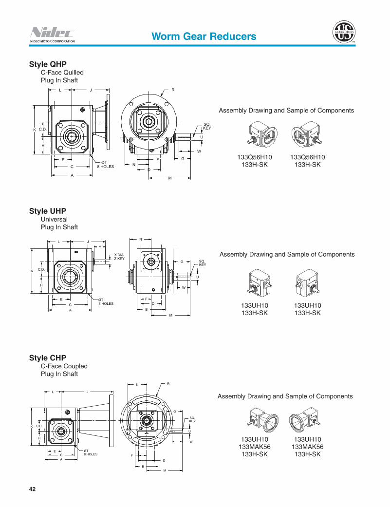
42
NIDEC MOTOR CORPORATION
Style UHP Universal Plug In Shaft
Style QHP C-Face Quilled Plug In Shaft
Worm Gear Reducers
Style CHP C-Face Coupled Plug In Shaft
Assembly Drawing and Sample of Components
L J
K
H
C.D.
E
C
A
ØT8 HOLES N
D
F
M
W
U
G
R
SQ.KEY
X DIA Z KEY
ØT8 HOLES
A C
E
H
C.D. K
L J Y
SQ.KEY
N
F
B D
M
W
U
G
J L
E C A
ØT8 HOLES
K
H
C.D.
F D
B M
W
U
SQ.KEY
G
R N
Assembly Drawing and Sample of Components
Assembly Drawing and Sample of Components
133Q56H10 133Q56H10133H-SK 133H-SK
133UH10 133UH10133H-SK 133H-SK
133UH10 133UH10133MAK56 133MAK56133H-SK 133H-SK

43
US
G
earm
oto
r
NIDEC MOTOR CORPORATION
DIMENSIONS (INCHES) FOR STYLE “UH”C.D. BASIC UNIT A B C D E F G H J K L M N1.33 133UH 4.00 2.88 3.25 2.00 1.63 1.00 2.00 1.72 4.03 4.66 2.12 4.49 2.661.75 175UH 4.81 3.38 4.19 2.75 2.09 1.38 1.91 2.06 4.68 5.75 2.75 4.92 2.852.06 206UH 5.50 3.75 5.00 2.88 2.50 1.44 2.00 2.28 5.06 6.38 3.00 5.43 3.222.62 262UH 7.12 4.44 6.38 3.38 3.19 1.69 2.50 2.94 6.23 8.00 3.69 6.21 3.443.25 325UH 5.00 5.00 7.50 4.00 3.75 2.00 3.25 3.50 7.06 9.38 4.50 7.74 4.29
C.D.T OUTPUT SHAFT INPUT SHAFT STOCK RATIOS MARKED “X”
U W SQ X Y Z KEY WT.LBS.
SIZE DEEP +.0015/.0000 KW LGTH
KEY +.000/-.001 SQ. LGTH. 5 10 15 20 25 30 40 50 60 60
1.33 5/16-18 0.50 0.625 1.313 0.188 0.500 1.81 0.125 1.38 X X X X X X X X X X 14.01.54 5/16-18 0.50 1.000 1.250 0.188 0.625 1.69 0.188 1.25 X X X X X X X X X X 20.01.75 5/16-18 0.61 1.000 1.375 0.188 0.625 1.81 0.188 1.50 X X X X X X X X X X 23.02.06 3/8-16 0.61 1.438 1.750 0.250 0.625 1.81 0.188 1.50 X X X X X X X X X X 28.02.37 3/8-16 0.60 1.438 1.750 0.250 0.750 1.94 0.188 1.31 X X X X X X X X X X 44.02.62 3/8-16 0.58 1.938 2.000 0.250 0.750 2.31 0.188 1.88 X X X X X X X X X X 54.03.00 7/16-14 0.80 2.188 2.250 0.250 0.875 2.26 0.188 1.31 X X X X X X X X X X 76.03.25 7/16-14 0.80 2.188 2.875 0.313 0.875 2.31 0.188 1.63 - X X X X X X X X X 79.0
DIMENSIONS (INCHES) FOR STYLE “QH”
C.D. BASIC UNIT
SHAFT KIT N.E.M.A. FRAME
A B C D E F G H J K L M N R
1.33 133Q56H 133H-SK 56C 4.00 2.88 3.25 2.00 1.63 1.00 2.00 1.72 3.94 4.66 2.12 4.49 2.66 3.251.75 175Q56H 175H-SK 56C 4.81 3.38 4.19 2.75 2.09 1.38 1.91 2.06 4.38 5.75 2.75 4.92 2.85 3.251.75 175Q140H 175H-SK 143/145TC 4.81 3.38 4.19 2.75 2.09 1.38 1.91 2.06 4.38 5.75 2.75 4.92 2.85 3.252.06 206Q56H 206H-SK 56C 5.50 3.75 5.00 2.88 2.50 1.44 2.00 2.28 4.75 6.38 3.00 5.43 3.22 3.252.06 206Q140H 206H-SK 143/145TC 5.50 3.75 5.00 2.88 2.50 1.44 2.00 2.28 4.75 6.38 3.00 5.43 3.22 3.252.62 262Q56H 262H-SK 56C 7.12 4.44 6.38 3.38 3.19 1.69 2.50 2.94 5.69 8.00 3.69 6.21 3.44 3.252.62 262Q140H 262H-SK 143/145TC 7.12 4.44 6.38 3.38 3.19 1.69 2.50 2.94 5.69 8.00 3.69 6.21 3.44 3.252.62 262Q180H 262H-SK 182/184TC 7.12 4.44 6.38 3.38 3.19 1.69 2.50 2.94 6.13 8.00 3.69 6.21 3.44 4.503.00 300Q180H 300H-SK 182/184TC 8.50 5.50 7.00 4.00 3.50 2.00 3.25 3.25 6.45 8.88 4.50 7.74 4.19 4.503.25 325Q56H 325H-SK 56C 8.50 5.00 7.50 4.00 3.75 2.00 3.25 3.50 6.56 9.38 4.50 7.74 4.25 3.253.25 325Q140H 325H-SK 143/145TC 8.50 5.00 7.50 4.00 3.75 2.00 3.25 3.50 6.56 9.38 4.50 7.74 4.25 3.253.25 325Q180H 325H-SK 182/184TC 8.50 5.00 7.50 4.00 3.75 2.00 3.25 3.50 7.00 9.38 4.50 7.74 4.25 4.50
C.D.N.E.M.A.FRAME
TOUTPUT SHAFT
INPUT SHAFTSTOCK RATIOS MARKED “X”
U W SQ WT.SIZE DEEP +.0015/.0000 KW LGTH KEY BORE KEYWAY 5 10 15 20 25 30 40 50 60 LBS.
1.33 56C 5/16-18 0.50 0.625 1.313 0.188 0.625 3/16X3/32 X X X X X X X X X 17.01.75 56C 5/16-18 0.61 1.000 1.375 0.188 0.625 3/16X3/32 X X X X X X X X X 25.01.75 143/145TC 5/16-18 0.61 1.000 1.375 0.188 0.875 3/16X3/32 X X X - - - - - - 25.02.06 56C 3/8-16 0.61 1.438 1.750 0.250 0.625 3/16X3/32 - X X X X X X X X 33.02.06 143/145TC 3/8-16 0.61 1.438 1.750 0.250 0.875 3/16X3/32 X X X X X - - - - 33.02.62 56C 3/8-16 0.58 1.938 2.000 0.250 0.625 3/16X3/32 - X X X X X X X X 57.02.62 143/145TC 3/8-16 0.58 1.938 2.000 0.250 0.875 3/16X3/32 - X X X X X X X X 57.02.62 182/184TC 3/8-16 0.58 1.938 2.000 0.250 1.125 1/4X1/8 X X - - - - - - - 57.03.25 56C 7/16-14 0.80 2.188 2.875 0.313 0.625 3/16X3/32 - X X X X X X X X 53.03.25 143/145TC 7/16-14 0.80 2.188 2.875 0.313 0.875 3/16X3/32 - X X X X X X X X 53.03.25 182/184TC 7/16-14 0.80 2.188 2.875 0.313 1.125 1/4X1/8 - X X X X X X X X 53.0
DIMENSIONS (INCHES) FOR STYLE “CH”
C.D. BASIC UNIT N.E.M.A. FRAME
A B C D E F G H J K L M N R
1.33 133Q56H 56C 4.00 2.88 3.25 2.00 1.63 1.00 2.00 1.72 6.38 4.66 2.12 4.49 2.66 3.251.75 175Q56H 56C 4.81 3.38 4.19 2.75 2.09 1.38 1.91 2.06 7.00 5.75 2.75 4.92 2.85 3.251.75 175Q140H 143/145TC 4.81 3.38 4.19 2.75 2.09 1.38 1.91 2.06 7.00 5.75 2.75 4.92 2.85 3.252.06 206Q56H 56C 5.50 3.75 5.00 2.88 2.50 1.44 2.00 2.28 7.37 6.38 3.00 5.43 3.22 3.252.06 206Q140H 143/145TC 5.50 3.75 5.00 2.88 2.50 1.44 2.00 2.28 7.37 6.38 3.00 5.43 3.22 3.252.62 262Q56H 56C 7.12 4.44 6.38 3.38 3.19 1.69 2.50 2.94 8.50 8.00 3.69 6.21 3.44 3.252.62 262Q140H 143/145TC 7.12 4.44 6.38 3.38 3.19 1.69 2.50 2.94 8.50 8.00 3.69 6.21 3.44 3.252.62 262Q180H 182/184TC 7.12 4.44 6.38 3.38 3.19 1.69 2.50 2.94 9.72 8.00 3.69 6.21 3.44 4.503.25 325Q56H 56C 8.50 5.00 7.50 4.00 3.75 2.00 3.25 3.50 9.37 9.38 4.50 7.74 4.25 3.253.25 325Q140H 143/145TC 8.50 5.00 7.50 4.00 3.75 2.00 3.25 3.50 9.37 9.38 4.50 7.74 4.25 3.253.25 325Q180H 182/184TC 8.50 5.00 7.50 4.00 3.75 2.00 3.25 3.50 10.59 9.38 4.50 7.74 4.25 4.50
C.D.N.E.M.A.FRAME
T OUTPUT SHAFT INPUT SHAFT STOCK RATIOS MARKED “X”U W SQ X Y Z KEY WT.
SIZE DEEP +.0015 /.0000
KW LGTH
KEY +.000/-.001
SQ. LGTH. 5 10 15 20 25 30 40 50 60 LBS.
1.33 56C 5/16-18 0.50 0.625 1.313 0.188 0.500 1.81 0.125 1.38 X X X X X X X X X 17.01.75 56C 5/16-18 0.61 1.000 1.375 0.188 0.625 1.81 0.188 1.50 X X X X X X X X X 25.01.75 143/145TC 5/16-18 0.61 1.000 1.375 0.188 0.625 1.81 0.188 1.50 X X X X X X X X X 25.02.06 56C 3/8-16 0.61 1.438 1.750 0.250 0.625 1.81 0.188 1.50 X X X X X X X X X 33.02.06 143/145TC 3/8-16 0.61 1.438 1.750 0.250 0.625 1.81 0.188 1.50 X X X X X X X X X 33.02.62 56C 3/8-16 0.58 1.938 2.000 0.250 0.750 2.31 0.188 1.88 X X X X X X X X X 57.02.62 143/145TC 3/8-16 0.58 1.938 2.000 0.250 0.750 2.31 0.188 1.88 X X X X X X X X X 57.02.62 182/184TC 3/8-16 0.58 1.938 2.000 0.250 0.750 2.31 0.188 1.88 X X X X X X X X X 57.03.25 56C 7/16-14 0.80 2.188 2.875 0.313 0.875 2.31 0.188 1.63 - X X X X X X X X 53.03.25 143/145TC 7/16-14 0.80 2.188 2.875 0.313 0.875 2.31 0.188 1.63 - X X X X X X X X 53.03.25 182/184TC 7/16-14 0.80 2.188 2.875 0.313 0.875 2.31 0.188 1.63 - X X X X X X X X 53.0
H To complete Part No. add shaft assembly (L, R, LR) and ratio symbol to size - for example 133Q56H10.u Components needed to make assembled reducer must be ordered separately.
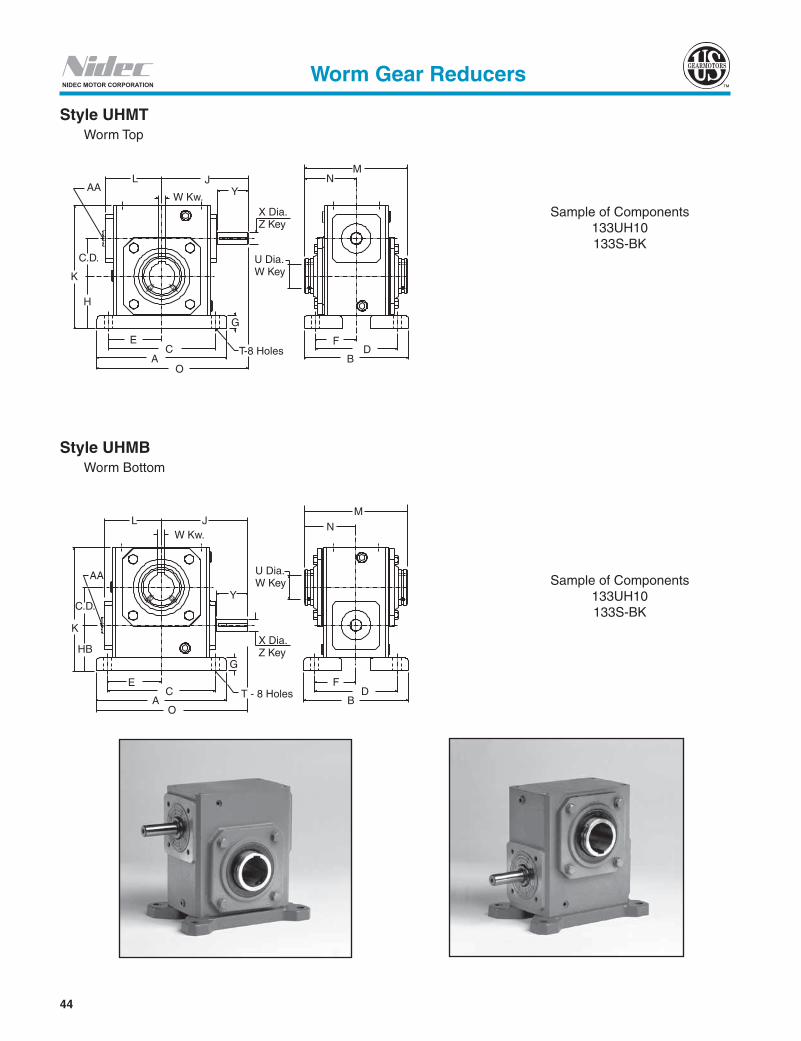
44
NIDEC MOTOR CORPORATION
Style UHMB Worm Bottom
Style UHMT Worm Top
Sample of Components133UH10133S-BK
Sample of Components133UH10133S-BK
AAL J
K
H
W Kw. Y
X Dia.Z Key
U Dia.W Key
C.D.
EC
AO
T-8 Holes
G
FD
B
MN
AA
K
C.D.
L J
HB
W Kw.
Y
X Dia.Z Key
MN
U Dia.W Key
T - 8 Holes
G
EC
AO
FD
B
Worm Gear Reducers

45
US
G
earm
oto
r
NIDEC MOTOR CORPORATION
Dimensions (Inches) for Style “UHMT” - With Base - Worm Top
Dimensions (Inches) forStyle “UHMB”
H To complete Part No. ratio symbol to size - for example 133UH10.u Components needed to make assembled reducer must be ordered separately. If Fan Kit is required, see the table above.s Select either Standard Base Kit (S-BK) are shown on page 59.
Worm Gear Reducers
C.D.
Components u
A B C D E F G H J K L M NBasic Unit H
Base Kits Standard
s
1.33 133UH 133S-BK 5.38 4.19 4.38 3.31 2.19 1.66 .47 2.25 4.03 5.19 2.12 5.31 2.66
1.75 175UH 175S-BK 7.00 5.56 5.75 4.50 2.88 2.25 .69 2.75 4.68 6.44 2.75 5.70 2.85
2.06 206UH 206S-BK 7.69 5.76 6.38 4.69 3.19 2.34 .72 3.00 5.06 7.09 2.75 6.44 3.22
2.62 262UH 262S-BK 9.25 6.50 8.00 5.25 4.00 2.63 .75 3.69 6.23 8.75 3.69 6.88 3.44
3.25 325UH 325S-BK 11.12 7.75 9.50 6.13 4.75 3.06 .88 4.38 7.06 10.25 4.50 8.50 4.25
3.75 375UH 375S-BK 12.00 8.63 10.38 7.00 5.19 3.50 .94 4.81 8.38 11.38 4.93 9.63 4.81
4.50 450UH 450S-BK 13.88 9.33 12.13 7.63 6.06 4.22 1.19 5.69 9.59 13.13 6.42 11.13 5.56
C.D. O T
OUTPUT BORE INPUT SHAFTStock Ratios marked “x” Wt.
Lbs.U
+.0015 -.0000
W KeywayX
+.000 -.001
YZ Key
Sq. Lgth. 5 10 15 20 25 30 40 50 60
1.33 6.72 .344 .6250 3/16 x 3/32 .500 1.81 .125 1.38 x x x x x x x x x 14.51.75 8.18 .406 1.0000 1/4 x 1/8 .625 1.81 .188 1.50 x x x x x x x x x 24.02.06 8.90 .469 1.4375 3/8 x 1/8 .625 1.81 .188 1.50 x x x x x x x x x 29.52.62 10.86 .531 1.9375 1/2 x 1/8 .750 2.31 .188 1.88 x x x x x x x x x 56.03.25 12.63 .531 2.1875 1/2 x 3/16 .875 2.31 .188 1.63 - x x x x x x x x 82.03.75 14.38 .594 2.4375 5/8 x 3/16 1.000 2.91 .250 1.75 - x x x x x x x x 119.04.50 16.53 .656 2.9375 3/4 x 1/4 1.125 3.48 .250 2.50 - x x x x x x x x 157.0
Components u
HBBasic Unit H
Base Kits Standard
s
133UH 133S-BK 2.14
175UH 175S-BK 2.63
206UH 206S-BK 2.75
262UH 262S-BK 3.19
325UH 325S-BK 3.50
375UH 375S-BK 3.75
450UH 450S-BK 4.06

46
NIDEC MOTOR CORPORATION
Style QHMT Worm Top
Style QHMB Worm Bottom
Sample of Components133Q56H10
133S-BK
Note: When mounting Style "QHMB", interference may occur; use a Riser Block or consult Application Engineering (1 800 626 2093).
Sample of Components133Q56H10
133S-BK
AA
L J
W Kw.
C.D.K
H
E U Dia.C
AT - 8 Holes
G
P
FD
NM
B
R
AA
L J
C.D.K
W Kw.
HB
G
U Dia.E
CA
T - 8 Holes
PB
FD
B
R
N
M
Worm Gear Reducers

47
US
G
earm
oto
r
NIDEC MOTOR CORPORATION
Dimensions (Inches) for Style “QHMT” With Base - Worm Top
Dimensions (Inches) for Style “QHMB”
H To complete Part No. add ratio symbol to size - for example 133Q56H10.u Components needed to make assembled reducer must be ordered separately.s Select either Standard Base Kit (S-BK).
Worm Gear Reducers
C.D. Componentsu N.E.M.A Frame
A
B C D E F G H J K L M N Basic UnitH Standard Base Kit s
1.33 133Q56H 133S-BK 56C 5.38 4.19 4.38 3.31 2.19 1.66 .47 2.25 3.94 5.19 2.12 5.31 2.66 1.75 175Q56H 175S-BK 56C 7.00 5.56 5.75 4.50 2.88 2.25 .69 2.75 4.38 6.44 2.75 5.70 2.85 1.75 175Q140H 175S-BK 143/145TC 7.00 5.56 5.75 4.50 2.88 2.25 .69 2.75 4.38 6.44 2.75 5.70 2.85 2.06 206Q56H 206S-BK 56C 7.69 5.76 6.38 4.69 3.19 2.34 .72 3.00 4.75 7.09 3.00 6.44 3.22 2.06 206Q140H 206S-BK 143/145TC 7.69 5.76 6.38 4.69 3.19 2.34 .72 3.00 4.75 7.09 3.00 6.44 3.22 2.62 262Q56H 262S-BK 56C 9.25 6.50 8.00 5.25 4.00 2.63 .75 3.69 5.69 8.75 3.69 6.88 3.44 2.62 262Q140H 262S-BK 143/145TC 9.25 6.50 8.00 5.25 4.00 2.63 .75 3.69 5.69 8.75 3.69 6.88 3.44 2.62 262Q180H 262S-BK 182/184TC 9.25 6.50 8.00 5.25 4.00 2.63 .75 3.69 6.13 8.75 3.69 6.88 3.44 3.25 325Q56H 325S-BK 56C 11.12 7.75 9.50 6.13 4.75 3.06 .88 4.38 6.56 10.25 4.50 8.50 4.25 3.25 325Q140H 325S-BK 143/145TC 11.12 7.75 9.50 6.13 4.75 3.06 .88 4.38 6.56 10.25 4.50 8.50 4.25 3.25 325Q180H 325S-BK 182/184TC 11.12 7.75 9.50 6.13 4.75 3.06 .88 4.38 7.00 10.25 4.50 8.50 4.25 3.75 375Q56H 375S-BK 56C 12.00 8.63 10.38 7.00 5.19 3.50 .94 4.81 6.01 11.38 4.93 9.63 4.81 3.75 375Q140H 375S-BK 143/145TC 12.00 8.63 10.38 7.00 5.19 3.50 .94 4.81 6.01 11.38 4.93 9.63 4.81 3.75 375Q180H 375S-BK 182/184TC 12.00 8.63 10.38 7.00 5.19 3.50 .94 4.81 7.29 11.38 4.93 9.63 4.81 3.75 375Q210H 375S-BK 213/215TC 12.00 8.63 10.38 7.00 5.19 3.50 .94 4.81 7.29 11.38 4.93 9.63 4.81 4.50 450Q140H 450S-BK 143/145TC 13.88 9.33 12.13 7.63 6.06 4.22 1.19 5.69 6.69 13.13 6.42 11.13 5.56 4.50 450Q180H 450S-BK 182/184TC 13.88 9.33 12.13 7.63 6.06 4.22 1.19 5.69 7.97 13.13 6.42 11.13 5.56 4.50 450Q210H 450S-BK 213/215TC 13.88 9.33 12.13 7.63 6.06 4.22 1.19 5.69 7.97 13.13 6.42 11.13 5.56
C.D. N.E.M.A.Frame P R T
INPUT OUTPUT BORE Stock Ratios marked "x"
Wt. Lbs.
U +.0015 -.0000
W KeywayBore Keyway 5 10 15 20 25 30 40 50 60
1.33 56C 3.58 3.25 .344 .625 3/16 x 3/32 .6250 3/16 x 3/32 x x x x x x x x x 17.5 1.75 56C 4.50 3.25 .406 .625 3/16 x 3/32 1.0000 1/4 x 1/8 x x x x x x x x x 26.0 1.75 143/145TC 4.50 3.25 .406 .875 3/16 x 3/32 1.0000 1/4 x 1/8 x x x - - - - - - 26.0 2.06 56C 5.06 3.25 .469 .625 3/16 x 3/32 1.4375 3/8 x 1/8 x x x x x x x x x 34.5 2.06 143/145TC 5.06 3.25 .469 .875 3/16 x 3/32 1.4375 3/8 x 1/8 x x x x x - - - - 34.5 2.62 56C 6.31 3.25 .469 .625 3/16 x 3/32 1.9375 1/2 x 1/8 - x x x x x x x x 59.0 2.62 143/145TC 6.31 3.25 .469 .875 3/16 x 3/32 1.9375 1/2 x 1/8 - x x x x x x x x 59.0 2.62 182/184TC 6.31 4.50 .469 1.125 1/4 x 1/8 1.9375 1/2 x 1/8 x x - - - - - - - 59.0 3.25 56C 7.63 3.25 .469 .625 3/16 x 3/32 2.1875 1/2 x 3/16 - x x x x x x x x 86.0 3.25 143/145TC 7.63 3.25 .469 .875 3/16 x 3/32 2.1875 1/2 x 3/16 - x x x x x x x x 86.0 3.25 182/184TC 7.93 4.50 .469 1.125 1/4 x 1/8 2.1875 1/2 x 3/16 - x x x x x x x x 86.0 3.75 56C 8.56 3.38 .594 .625 3/16 x 3/32 2.4375 5/8 x 3/16 - - - - - - x x x 126.0 3.75 143/145TC 8.56 3.38 .594 .875 3/16 x 3/32 2.4375 5/8 x 3/16 - x x x x x x x x 126.0 3.75 182/184TC 8.56 4.50 .594 1.125 1/4 x 1/8 2.4375 5/8 x 3/16 - x x x x x x x - 126.0 3.75 213/215TC 8.56 4.50 .594 1.375 5/16 x 5/32 2.4375 5/8 x 3/16 - x x - - - - - - 126.0 4.50 143/145TC 10.19 3.38 .656 .875 3/16 x 3/32 2.9375 3/4 x 1/4 - - x x - - x x x 167.0 4.50 182/184TC 10.19 4.50 .656 1.125 1/4 x 1/8 2.9375 3/4 x 1/4 - - x x x x x x x 167.0 4.50 213/215TC 10.19 4.50 .656 1.375 5/16 x 5/32 2.9375 3/4 x 1/4 - x x x x - - - - 167.0
ComponentsuHB PB Ref. No. Base Kits
Standards 133QH 133S-BK 2.14 3.47175QH 175S-BK 2.63 4.38206QH 206S-BK 2.75 4.81262QH 262S-BK 3.19 5.81325QH 325S-BK 3.50 6.25375QH 375S-BK 3.75 7.50450QH 450S-BK 4.06 8.63

48
NIDEC MOTOR CORPORATION
Style CHMT Worm Top
Style CHMB Worm Bottom
Sample of Components133UH10133S-BK
133MAK56
Sample of Components133UH10133S-BK
133MAK56
Note: When mounting Style "CHMB", interference may occur; use a Riser Block or consult Application Engineering (1 800 626 2093).
AA
L J
KC.D.
W Kw.
PH
T - 8 Holes
G
E
AC
U Dia.
MN
BD
F
R
AA
L J
K
C.D.
W Kw.
HB
G
U Dia.E
CA
T - 8 Holes
PB
F
R
DB
MN
Worm Gear Reducers

49
US
G
earm
oto
r
NIDEC MOTOR CORPORATION
H To complete Part No. ratio symbol to size - for example 133UH10.u Components needed to make assembled reducer must be ordered separately.s Select either Standard Base Kit (S-BK).
Worm Gear Reducers
Dimensions (Inches) for Style “CHMT” - With Base - Worm Top
C.D.Components u
A B C D E F G H K L M NBasic UnitH Adapter Base Kit ▲
Standard1.33 133UH
See Adapter Kit Table Below
133S-BK 5.38 4.19 4.38 3.31 2.19 1.66 .47 2.25 5.19 2.12 5.31 2.661.75 175UH 175S-BK 7.00 5.56 5.75 4.50 2.88 2.25 .69 2.75 6.44 2.75 5.70 2.852.06 206UH 206S-BK 7.69 5.76 6.38 4.69 3.19 2.34 .72 3.00 7.09 3.00 6.44 3.222.62 262UH 262S-BK 9.25 6.50 8.00 5.25 4.00 2.63 .75 3.69 8.75 3.69 6.88 3.443.25 325UH 325S-BK 11.12 7.75 9.50 6.13 4.75 3.06 .88 4.38 10.25 4.50 8.50 4.253.75 375UH 375S-BK 12.00 8.63 10.38 7.00 5.19 3.50 .94 4.81 11.38 4.93 9.63 4.814.50 450UH 450S-BK 13.88 9.33 12.13 7.63 6.06 4.22 1.19 5.69 13.13 6.42 11.13 5.56
C.D. P T
OUTPUT BORE Stock Ratios marked “x” Wt.
Lbs.U
+.0015 -.0000
W Keyway5 10 15 20 25 30 40 50 60
1.33 3.58 .344 .6250 3/16 x 3/32 x x x x x x x x x 21.51.75 4.50 .406 1.0000 1/4 x 1/8 x x x x x x x x x 31.02.06 5.06 .469 1.4375 3/8 x 1/8 x x x x x x x x x 36.52.62 6.31 .531 1.9375 1/2 x 1/8 x x x x x x x x x 67.03.25 7.63 .531 2.1875 1/2 x 3/16 - x x x x x x x x 93.03.75 8.56 .594 2.4375 5/8 x 3/16 - x x x x x x x x 131.54.50 10.19 .656 2.9375 3/4 x 1/4 - x x x x x x x x 173.0
Dimensions (Inches) for Style “CHMB”
Components uHB PB
Basic Unit H Adapter Kit Base Kit s Standard
133UH
See Adapter Kit Table Below
133S-BK 2.14 3.47175UH 175S-BK 2.63 4.38206UH 206S-BK 2.75 4.81262UH 262S-BK 3.19 5.81325UH 325S-BK 3.50 6.75375UH 375S-BK 3.75 7.50450UH 450S-BK 4.06 8.63
N.E.M.A. Frame Adapter Kits and Dimensions
C.D.
56C 143/145TC 182/184TC 213/215TCInput: .625
Kw.: 3/16 x 3/32Input: .875
Kw.: 3/16 x 3/32Input: 1.125
KW.: 1/4 x 1/8Input: 1.375
Kw.: 5/16 x 5/32Adapter Kit No. J R Adapter Kit No. J R Adapter Kit No. J R Adapter Kit No. J R
1.33 133MAK56 6.38 3.25 133MAK140 6.38 3.25 - - - - - -1.75 154-206MAK56 7.00 3.25 154-206MAK140 7.00 3.25 - - - - - -2.06 154-206MAK56 7.37 3.25 154-206MAK140 7.37 3.25 - - - - - -2.62 262MAK56 8.50 3.25 262MAK140 8.50 3.25 262MAK180 9.72 4.50 - - -3.25 300-325MAK56 9.37 3.25 300-325MAK140 9.37 3.25 300-325MAK180 10.59 4.50 325MAK210 10.59 4.503.75 375MAK56 11.74 3.38 375MAK140 11.47 3.38 375MAK180 12.92 4.50 375MAK210 12.92 4.504.50 - - - 450MAK140 12.15 3.38 450MAK180 13.60 4.50 450MAK210 13.60 4.50
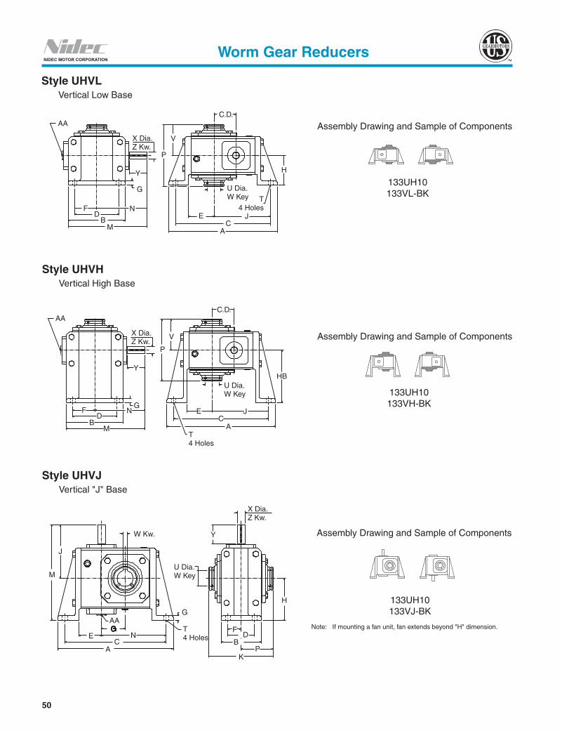
50
NIDEC MOTOR CORPORATION
Style UHVL Vertical Low Base
Style UHVJ Vertical "J" Base
Style UHVH Vertical High Base
Assembly Drawing and Sample of Components
133UH10 133VL-BK
Assembly Drawing and Sample of Components
133UH10 133VH-BK
Assembly Drawing and Sample of Components
133UH10 133VJ-BK
Note: If mounting a fan unit, fan extends beyond "H" dimension.
AA
X Dia.Z Kw.
G
Y
NFD
BM A
CJE
T4 Holes
H
U Dia.W Key
P
V
C.D.
AA
X Dia.Z Kw.
Y
P
V
FD
BM
NG
T4 Holes
EC
A
J
U Dia.W Key
HB
C.D.
G
M
W Kw.
U Dia.W Key
J
T4 Holes
AAG
NC
A
E
KP
FD
B
H
X Dia.Z Kw.
Y
Worm Gear Reducers

51
US
G
earm
oto
r
NIDEC MOTOR CORPORATION
H To complete Part No. ratio symbol to size - for example 133UH10.u Components needed to make assembled reducer must be ordered separately.
Worm Gear Reducers
Dimensions (Inches) for Style “UHVJ” - With Vertical “J” Base
Components uA B C D E F G H J K M N P T Wt.
Lbs.Base Unit H Base Kit133U 133VJ-BK 7.28 2.88 6.42 2.00 1.66 1.00 .53 2.94 4.03 5.31 6.97 3.93 2.66 .344 15.0175U 175VJ-BK 8.63 3.38 7.63 2.50 2.00 1.25 .69 3.50 4.68 5.70 8.18 4.75 2.85 .406 25.0206U 206VJ-BK 9.75 3.75 8.62 2.62 2.09 1.31 .72 3.94 5.06 6.44 9.00 5.46 3.22 .469 31.0262U 262VJ-BK 11.75 4.44 10.38 3.13 2.50 1.56 .75 4.75 6.23 6.88 10.98 6.75 3.44 .531 58.0325U 325VJ-BK 14.00 5.00 12.75 4.00 2.69 2.00 .81 5.69 7.06 8.50 12.75 8.44 4.25 .531 85.0375U 375VJ-BK 15.06 6.25 13.31 4.75 2.94 2.38 .88 6.00 8.38 9.63 14.38 9.06 4.81 .594 117.5450U 450VJ-BK 16.94 7.38 14.94 5.81 3.06 2.91 .88 7.38 9.59 11.13 16.96 10.50 5.56 .688 151.0
Dimensions (Inches) for Style “UHVL” - With Vertical Low Base
C.D.Components u
A B C D E F G H J M N P T VBasic Unit H Base Kit
1.33 133UH 133VL-BK 7.10 4.00 6.16 3.25 1.81 1.63 .53 2.31 3.69 6.03 4.03 5.31 .344 2.661.75 175UH 175VL-BK 8.44 4.81 7.38 4.00 2.12 2.00 .69 3.00 4.50 7.09 4.68 5.70 .406 2.852.06 206UH 206VL-BK 9.50 5.63 8.38 4.88 2.34 2.44 .72 3.13 5.09 7.87 5.06 6.44 .469 3.222.62 262UH 262VL-BK 11.25 7.13 10.13 5.75 3.00 2.88 .75 3.63 6.13 9.79 6.23 6.88 .531 3.443.25 325UH 325VL-BK 13.38 8.50 11.88 6.13 3.56 3.06 .81 4.69 7.13 11.31 7.06 8.50 .531 4.253.75 375UH 375VL-BK 15.69 10.50 13.94 8.00 3.44 4.00 .88 5.25 8.31 13.13 8.38 9.63 .594 4.814.50 450UH 450VL-BK 16.94 10.88 14.94 9.56 4.63 4.78 .88 5.06 8.94 15.09 9.59 11.13 .688 5.56
C.D.
OUTPUT BORE INPUT SHAFTStock Ratios marked “x” Wt.
Lbs.U
+.0015 -.0000
W KeywayX
+ .000 -.001
YZ Ke y
Sq. Lgth. 5 10 15 20 25 30 40 50 601.33 .6250 3/16 x 3/32 .500 1.81 .125 1.38 x x x x x x x x x 16.31.75 1.0000 1/4 x 1/8 .625 1.81 .188 1.50 x x x x x x x x x 27.52.06 1.4375 3/8 x 1/8 .625 1.81 .188 1.50 x x x x x x x x x 35.02.62 1.9375 1/2 x 1/8 .750 2.31 .188 1.88 x x x x x x x x x 63.03.25 2.1875 1/2 x 3/16 .875 2.31 .188 1.63 - x x x x x x x x 95.03.75 2.4375 5/8 x 3/16 1.000 2.91 .250 1.75 - x x x x x x x x 134.04.50 2.9375 3/4 x 1/4 1.125 3.48 .250 2.50 - x x x x x x x x 173.0
Dimensions (Inches) for Style “UHVH”
Components uHB Wt.
Lbs.Basic Unit H Base Kit133UH 133VH-BK 3.56 17.3175UH 175VH-BK 4.38 28.5206UH 206VH-BK 4.38 36.0262UH 262VH-BK 5.60 67.0325UH 325VH-BK 6.25 98.0375UH 375VH-BK 7.00 137.5450UH 450VH-BK 8.56 181.0
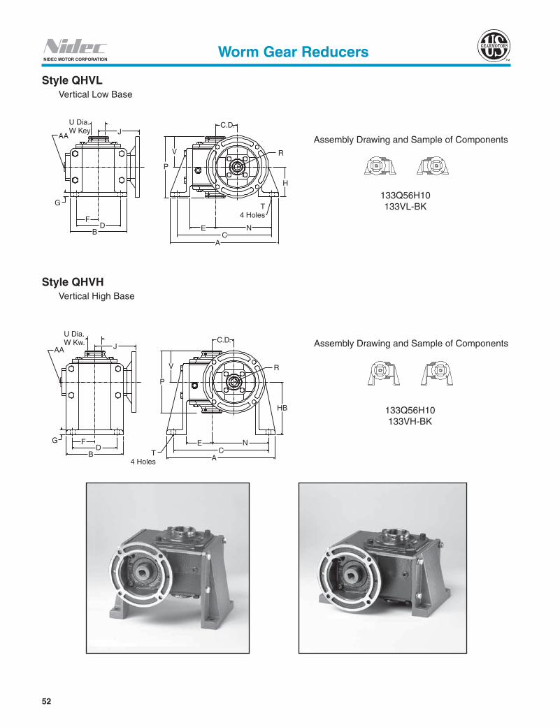
52
NIDEC MOTOR CORPORATION
Style QHVL Vertical Low Base
Assembly Drawing and Sample of Components
133Q56H10 133VL-BK
Style QHVH Vertical High Base
Assembly Drawing and Sample of Components
133Q56H10 133VH-BK
AA
U Dia.W Key J
C.D.
V
P
F
G
DB E N
T4 Holes
CA
R
H
AA
U Dia.W Kw. J
G FD
B T4 Holes
E NC
A
HB
R
C.D.
V
P
Worm Gear Reducers
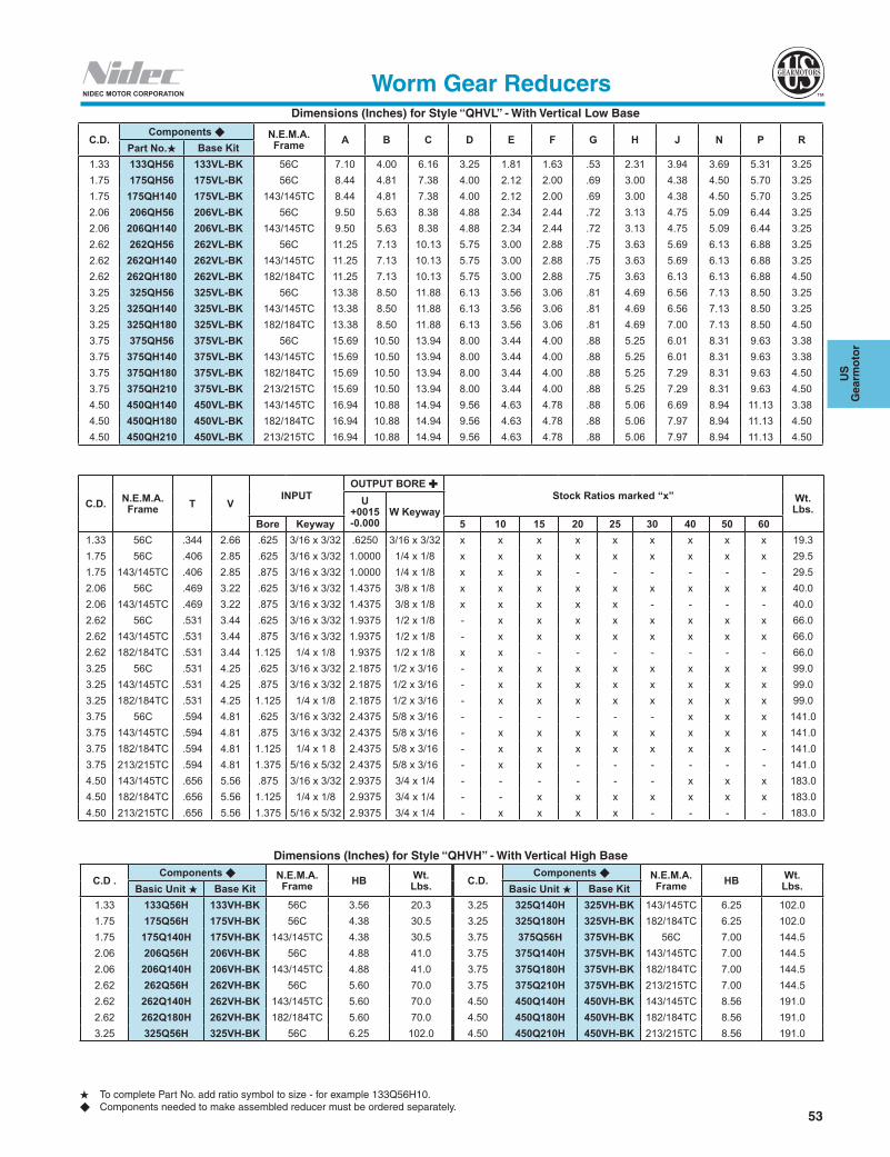
53
US
G
earm
oto
r
NIDEC MOTOR CORPORATION
Dimensions (Inches) for Style “QHVL” - With Vertical Low Base
H To complete Part No. add ratio symbol to size - for example 133Q56H10.u Components needed to make assembled reducer must be ordered separately.
Worm Gear Reducers
C.D.Components u N.E.M.A.
Frame A B C D E F G H J N P RPart No.H Base Kit
1.33 133QH56 133VL-BK 56C 7.10 4.00 6.16 3.25 1.81 1.63 .53 2.31 3.94 3.69 5.31 3.251.75 175QH56 175VL-BK 56C 8.44 4.81 7.38 4.00 2.12 2.00 .69 3.00 4.38 4.50 5.70 3.251.75 175QH140 175VL-BK 143/145TC 8.44 4.81 7.38 4.00 2.12 2.00 .69 3.00 4.38 4.50 5.70 3.252.06 206QH56 206VL-BK 56C 9.50 5.63 8.38 4.88 2.34 2.44 .72 3.13 4.75 5.09 6.44 3.252.06 206QH140 206VL-BK 143/145TC 9.50 5.63 8.38 4.88 2.34 2.44 .72 3.13 4.75 5.09 6.44 3.252.62 262QH56 262VL-BK 56C 11.25 7.13 10.13 5.75 3.00 2.88 .75 3.63 5.69 6.13 6.88 3.252.62 262QH140 262VL-BK 143/145TC 11.25 7.13 10.13 5.75 3.00 2.88 .75 3.63 5.69 6.13 6.88 3.252.62 262QH180 262VL-BK 182/184TC 11.25 7.13 10.13 5.75 3.00 2.88 .75 3.63 6.13 6.13 6.88 4.503.25 325QH56 325VL-BK 56C 13.38 8.50 11.88 6.13 3.56 3.06 .81 4.69 6.56 7.13 8.50 3.253.25 325QH140 325VL-BK 143/145TC 13.38 8.50 11.88 6.13 3.56 3.06 .81 4.69 6.56 7.13 8.50 3.253.25 325QH180 325VL-BK 182/184TC 13.38 8.50 11.88 6.13 3.56 3.06 .81 4.69 7.00 7.13 8.50 4.503.75 375QH56 375VL-BK 56C 15.69 10.50 13.94 8.00 3.44 4.00 .88 5.25 6.01 8.31 9.63 3.383.75 375QH140 375VL-BK 143/145TC 15.69 10.50 13.94 8.00 3.44 4.00 .88 5.25 6.01 8.31 9.63 3.383.75 375QH180 375VL-BK 182/184TC 15.69 10.50 13.94 8.00 3.44 4.00 .88 5.25 7.29 8.31 9.63 4.503.75 375QH210 375VL-BK 213/215TC 15.69 10.50 13.94 8.00 3.44 4.00 .88 5.25 7.29 8.31 9.63 4.504.50 450QH140 450VL-BK 143/145TC 16.94 10.88 14.94 9.56 4.63 4.78 .88 5.06 6.69 8.94 11.13 3.384.50 450QH180 450VL-BK 182/184TC 16.94 10.88 14.94 9.56 4.63 4.78 .88 5.06 7.97 8.94 11.13 4.504.50 450QH210 450VL-BK 213/215TC 16.94 10.88 14.94 9.56 4.63 4.78 .88 5.06 7.97 8.94 11.13 4.50
C.D. N.E.M.A. Frame T V
INPUTOUTPUT BORE
Stock Ratios marked “x” Wt. Lbs.
U +0015 -0.000
W KeywayBore Keyway 5 10 15 20 25 30 40 50 60
1.33 56C .344 2.66 .625 3/16 x 3/32 .6250 3/16 x 3/32 x x x x x x x x x 19.31.75 56C .406 2.85 .625 3/16 x 3/32 1.0000 1/4 x 1/8 x x x x x x x x x 29.51.75 143/145TC .406 2.85 .875 3/16 x 3/32 1.0000 1/4 x 1/8 x x x - - - - - - 29.52.06 56C .469 3.22 .625 3/16 x 3/32 1.4375 3/8 x 1/8 x x x x x x x x x 40.02.06 143/145TC .469 3.22 .875 3/16 x 3/32 1.4375 3/8 x 1/8 x x x x x - - - - 40.02.62 56C .531 3.44 .625 3/16 x 3/32 1.9375 1/2 x 1/8 - x x x x x x x x 66.02.62 143/145TC .531 3.44 .875 3/16 x 3/32 1.9375 1/2 x 1/8 - x x x x x x x x 66.02.62 182/184TC .531 3.44 1.125 1/4 x 1/8 1.9375 1/2 x 1/8 x x - - - - - - - 66.03.25 56C .531 4.25 .625 3/16 x 3/32 2.1875 1/2 x 3/16 - x x x x x x x x 99.03.25 143/145TC .531 4.25 .875 3/16 x 3/32 2.1875 1/2 x 3/16 - x x x x x x x x 99.03.25 182/184TC .531 4.25 1.125 1/4 x 1/8 2.1875 1/2 x 3/16 - x x x x x x x x 99.03.75 56C .594 4.81 .625 3/16 x 3/32 2.4375 5/8 x 3/16 - - - - - - x x x 141.03.75 143/145TC .594 4.81 .875 3/16 x 3/32 2.4375 5/8 x 3/16 - x x x x x x x x 141.03.75 182/184TC .594 4.81 1.125 1/4 x 1 8 2.4375 5/8 x 3/16 - x x x x x x x - 141.03.75 213/215TC .594 4.81 1.375 5/16 x 5/32 2.4375 5/8 x 3/16 - x x - - - - - - 141.04.50 143/145TC .656 5.56 .875 3/16 x 3/32 2.9375 3/4 x 1/4 - - - - - - x x x 183.04.50 182/184TC .656 5.56 1.125 1/4 x 1/8 2.9375 3/4 x 1/4 - - x x x x x x x 183.04.50 213/215TC .656 5.56 1.375 5/16 x 5/32 2.9375 3/4 x 1/4 - x x x x - - - - 183.0
Dimensions (Inches) for Style “QHVH” - With Vertical High Base
C.D .Components u N.E.M.A.
Frame HB Wt. Lbs. C.D.
Components u N.E.M.A. Frame HB Wt.
Lbs.Basic Unit H Base Kit Basic Unit H Base Kit1.33 133Q56H 133VH-BK 56C 3.56 20.3 3.25 325Q140H 325VH-BK 143/145TC 6.25 102.01.75 175Q56H 175VH-BK 56C 4.38 30.5 3.25 325Q180H 325VH-BK 182/184TC 6.25 102.01.75 175Q140H 175VH-BK 143/145TC 4.38 30.5 3.75 375Q56H 375VH-BK 56C 7.00 144.52.06 206Q56H 206VH-BK 56C 4.88 41.0 3.75 375Q140H 375VH-BK 143/145TC 7.00 144.52.06 206Q140H 206VH-BK 143/145TC 4.88 41.0 3.75 375Q180H 375VH-BK 182/184TC 7.00 144.52.62 262Q56H 262VH-BK 56C 5.60 70.0 3.75 375Q210H 375VH-BK 213/215TC 7.00 144.52.62 262Q140H 262VH-BK 143/145TC 5.60 70.0 4.50 450Q140H 450VH-BK 143/145TC 8.56 191.02.62 262Q180H 262VH-BK 182/184TC 5.60 70.0 4.50 450Q180H 450VH-BK 182/184TC 8.56 191.03.25 325Q56H 325VH-BK 56C 6.25 102.0 4.50 450Q210H 450VH-BK 213/215TC 8.56 191.0

54
NIDEC MOTOR CORPORATION
Style QHVJ Vertical "J" Base
Sample of Components
133Q56H10133VJ-BK
Note: If mounting fan unit, fan extends beyond "H" dimension.
R
J
AA
EC.D.
W Kw.
NC
A
T4 Holes
G
FD
BP
K
H
U Dia.W Key
Worm Gear Reducers
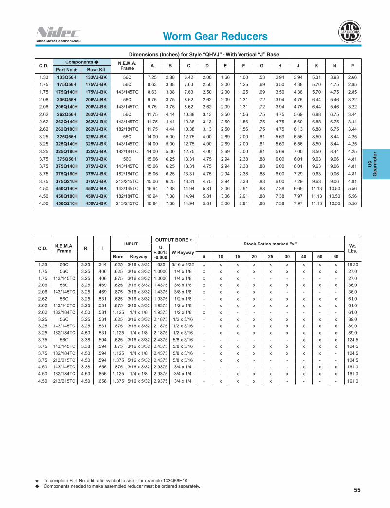
55
US
G
earm
oto
r
NIDEC MOTOR CORPORATION
Dimensions (Inches) for Style “QHVJ” - With Vertical “J” Base
H To complete Part No. add ratio symbol to size - for example 133Q56H10.u Components needed to make assembled reducer must be ordered separately.
Worm Gear Reducers
C.D.Components u N.E.M.A.
Frame A B C D E F G H J K N PPart No.H Base Kit
1.33 133Q56H 133VJ-BK 56C 7.25 2.88 6.42 2.00 1.66 1.00 .53 2.94 3.94 5.31 3.93 2.661.75 175Q56H 175VJ-BK 56C 8.63 3.38 7.63 2.50 2.00 1.25 .69 3.50 4.38 5.70 4.75 2.851.75 175Q140H 175VJ-BK 143/145TC 8.63 3.38 7.63 2.50 2.00 1.25 .69 3.50 4.38 5.70 4.75 2.852.06 206Q56H 206VJ-BK 56C 9.75 3.75 8.62 2.62 2.09 1.31 .72 3.94 4.75 6.44 5.46 3.222.06 206Q140H 206VJ-BK 143/145TC 9.75 3.75 8.62 2.62 2.09 1.31 .72 3.94 4.75 6.44 5.46 3.222.62 262Q56H 262VJ-BK 56C 11.75 4.44 10.38 3.13 2.50 1.56 .75 4.75 5.69 6.88 6.75 3.442.62 262Q140H 262VJ-BK 143/145TC 11.75 4.44 10.38 3.13 2.50 1.56 .75 4.75 5.69 6.88 6.75 3.442.62 262Q180H 262VJ-BK 182/184TC 11.75 4.44 10.38 3.13 2.50 1.56 .75 4.75 6.13 6.88 6.75 3.443.25 325Q56H 325VJ-BK 56C 14.00 5.00 12.75 4.00 2.69 2.00 .81 5.69 6.56 8.50 8.44 4.253.25 325Q140H 325VJ-BK 143/145TC 14.00 5.00 12.75 4.00 2.69 2.00 .81 5.69 6.56 8.50 8.44 4.253.25 325Q180H 325VJ-BK 182/184TC 14.00 5.00 12.75 4.00 2.69 2.00 .81 5.69 7.00 8.50 8.44 4.253.75 375Q56H 375VJ-BK 56C 15.06 6.25 13.31 4.75 2.94 2.38 .88 6.00 6.01 9.63 9.06 4.813.75 375Q140H 375VJ-BK 143/145TC 15.06 6.25 13.31 4.75 2.94 2.38 .88 6.00 6.01 9.63 9.06 4.813.75 375Q180H 375VJ-BK 182/184TC 15.06 6.25 13.31 4.75 2.94 2.38 .88 6.00 7.29 9.63 9.06 4.813.75 375Q210H 375VJ-BK 213/215TC 15.06 6.25 13.31 4.75 2.94 2.38 .88 6.00 7.29 9.63 9.06 4.814.50 450Q140H 450VJ-BK 143/145TC 16.94 7.38 14.94 5.81 3.06 2.91 .88 7.38 6.69 11.13 10.50 5.564.50 450Q180H 450VJ-BK 182/184TC 16.94 7.38 14.94 5.81 3.06 2.91 .88 7.38 7.97 11.13 10.50 5.564.50 450Q210H 450VJ-BK 213/215TC 16.94 7.38 14.94 5.81 3.06 2.91 .88 7.38 7.97 11.13 10.50 5.56
C.D. N.E.M.A. Frame R T
INPUTOUTPUT BORE +
Stock Ratios marked "x" Wt. Lbs.
U +.0015 -0.000
W KeywayBore Keyway 5 10 15 20 25 30 40 50 60
1.33 56C 3.25 .344 .625 3/16 x 3/32 .625 3/16 x 3/32 x x x x x x x x x 18.301.75 56C 3.25 .406 .625 3/16 x 3/32 1.0000 1/4 x 1/8 x x x x x x x x x 27.01.75 143/145TC 3.25 .406 .875 3/16 x 3/32 1.0000 1/4 x 1/8 x x x - - - - - - 27.02.06 56C 3.25 .469 .625 3/16 x 3/32 1.4375 3/8 x 1/8 x x x x x x x x x 36.02.06 143/145TC 3.25 .469 .875 3/16 x 3/32 1.4375 3/8 x 1/8 x x x x x - - - - 36.02.62 56C 3.25 .531 .625 3/16 x 3/32 1.9375 1/2 x 1/8 - x x x x x x x x 61.02.62 143/145TC 3.25 .531 .875 3/16 x 3/32 1.9375 1/2 x 1/8 - x x x x x x x x 61.02.62 182/184TC 4.50 .531 1.125 1/4 x 1/8 1.9375 1/2 x 1/8 x x - - - - - - - 61.03.25 56C 3.25 .531 .625 3/16 x 3/32 2.1875 1/2 x 3/16 - x x x x x x x x 89.03.25 143/145TC 3.25 .531 .875 3/16 x 3/32 2.1875 1/2 x 3/16 - x x x x x x x x 89.03.25 182/184TC 4.50 .531 1.125 1/4 x 1/8 2.1875 1/2 x 3/16 - x x x x x x x x 89.03.75 56C 3.38 .594 .625 3/16 x 3/32 2.4375 5/8 x 3/16 - - - - - - x x x 124.53.75 143/145TC 3.38 .594 .875 3/16 x 3/32 2.4375 5/8 x 3/16 - x x x x x x x x 124.53.75 182/184TC 4.50 .594 1.125 1/4 x 1/8 2.4375 5/8 x 3/16 - x x x x x x x - 124.53.75 213/215TC 4.50 .594 1.375 5/16 x 5/32 2.4375 5/8 x 3/16 - x x - - - - - - 124.54.50 143/145TC 3.38 .656 .875 3/16 x 3/32 2.9375 3/4 x 1/4 - - - - - - x x x 161.04.50 182/184TC 4.50 .656 1.125 1/4 x 1/8 2.9375 3/4 x 1/4 - - x x x x x x x 161.04.50 213/215TC 4.50 .656 1.375 5/16 x 5/32 2.9375 3/4 x 1/4 - x x x x - - - - 161.0

56
NIDEC MOTOR CORPORATION
Style CHVL Vertical Low Base
Style CHVJ Vertical "J" Base
Assembly Drawing and Sample of Components
133UH10 133VH-BK 133MAK56
Assembly Drawing and Sample of Components
133UH10 133VL-BK 133MAK56
Sample of Components
133UH10133VJ-BK133MAK56
Note: If mounting fan unit, fan extends beyond "H" dimension.
Style CHVH Vertical High Base
AA
J
G
P
FD
BE N
CA
H
R
T4 Holes
V
C.D.U Dia.W Kw.
AA
JU Dia.W Kw.
V
P
G FD
BT
4 Holes
E NC
A
HB
R
C.D.
J
R
AA
C.D.E N
CA
W Key T4 Holes
G
FD
BP
K
H
U Dia.W Key
Worm Gear Reducers
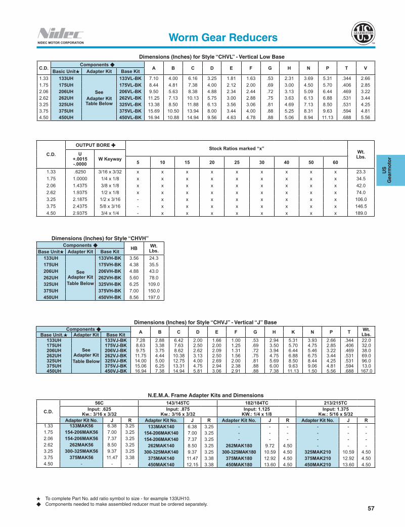
57
US
G
earm
oto
r
NIDEC MOTOR CORPORATION
H To complete Part No. add ratio symbol to size - for example 133UH10.u Components needed to make assembled reducer must be ordered separately.
Worm Gear Reducers
N.E.M.A. Frame Adapter Kits and Dimensions
C.D.
56C 143/145TC 182/184TC 213/215TCInput: .625
Kw.: 3/16 x 3/32Input: .875
Kw.: 3/16 x 3/32Input: 1.125
KW.: 1/4 x 1/8Input: 1.375
Kw.: 5/16 x 5/32Adapter Kit No. J R Adapter Kit No. J R Adapter Kit No. J R Adapter Kit No. J R
1.33 133MAK56 6.38 3.25 133MAK140 6.38 3.25 - - - - - -1.75 154-206MAK56 7.00 3.25 154-206MAK140 7.00 3.25 - - - - - -2.06 154-206MAK56 7.37 3.25 154-206MAK140 7.37 3.25 - - - - - -2.62 262MAK56 8.50 3.25 262MAK140 8.50 3.25 262MAK180 9.72 4.50 - - -3.25 300-325MAK56 9.37 3.25 300-325MAK140 9.37 3.25 300-325MAK180 10.59 4.50 325MAK210 10.59 4.503.75 375MAK56 11.47 3.38 375MAK140 11.47 3.38 375MAK180 12.92 4.50 375MAK210 12.92 4.504.50 - - - 450MAK140 12.15 3.38 450MAK180 13.60 4.50 450MAK210 13.60 4.50
Dimensions (Inches) for Style “CHVL” - Vertical Low Base
C.D.Components u
A B C D E F G H N P T VBasic UnitH Adapter Kit Base Kit
1.33 133UH
SeeAdapter Kit Table Below
133VL-BK 7.10 4.00 6.16 3.25 1.81 1.63 .53 2.31 3.69 5.31 .344 2.661.75 175UH 175VL-BK 8.44 4.81 7.38 4.00 2.12 2.00 .69 3.00 4.50 5.70 .406 2.852.06 206UH 206VL-BK 9.50 5.63 8.38 4.88 2.34 2.44 .72 3.13 5.09 6.44 .469 3.222.62 262UH 262VL-BK 11.25 7.13 10.13 5.75 3.00 2.88 .75 3.63 6.13 6.88 .531 3.443.25 325UH 325VL-BK 13.38 8.50 11.88 6.13 3.56 3.06 .81 4.69 7.13 8.50 .531 4.253.75 375UH 375VL-BK 15.69 10.50 13.94 8.00 3.44 4.00 .88 5.25 8.31 9.63 .594 4.814.50 450UH 450VL-BK 16.94 10.88 14.94 9.56 4.63 4.78 .88 5.06 8.94 11.13 .688 5.56
C.D.
OUTPUT BORE Stock Ratios marked “x”
Wt. Lbs.U
+.0015 -.0000
W Keyway5 10 15 20 25 30 40 50 60
1.33 .6250 3/16 x 3/32 x x x x x x x x x 23.31.75 1.0000 1/4 x 1/8 x x x x x x x x x 34.52.06 1.4375 3/8 x 1/8 x x x x x x x x x 42.02.62 1.9375 1/2 x 1/8 x x x x x x x x x 74.03.25 2.1875 1/2 x 3/16 - x x x x x x x x 106.03.75 2.4375 5/8 x 3/16 - x x x x x x x x 146.54.50 2.9375 3/4 x 1/4 - x x x x x x x x 189.0
Dimensions (Inches) for Style “CHVH”Components u HB Wt.
Lbs.Base UnitH Adapter Kit Base Kit133UH
See Adapter KitTable Below
133VH-BK 3.56 24.3175UH 175VH-BK 4.38 35.5206UH 206VH-BK 4.88 43.0262UH 262VH-BK 5.60 78.0325UH 325VH-BK 6.25 109.0375UH 375VH-BK 7.00 150.0450UH 450VH-BK 8.56 197.0
Dimensions (Inches) for Style “CHVJ” - Vertical “J” BaseComponents u A B C D E F G H K N P T Wt.
Lbs.Base Unit.H Adapter Kit Base Kit133UH
See Adapter KitTable Below
133VJ-BK 7.28 2.88 6.42 2.00 1.66 1.00 .53 2.94 5.31 3.93 2.66 .344 22.0175UH 175VJ-BK 8.63 3.38 7.63 2.50 2.00 1.25 .69 3.50 5.70 4.75 2.85 .406 32.0206UH 206VJ-BK 9.75 3.75 8.62 2.62 2.09 1.31 .72 3.94 6.44 5.46 3.22 .469 38.0262UH 262VJ-BK 11.75 4.44 10.38 3.13 2.50 1.56 .75 4.75 6.88 6.75 3.44 .531 69.0325UH 325VJ-BK 14.00 5.00 12.75 4.00 2.69 2.00 .81 5.69 8.50 8.44 4.25 .531 96.0375UH 375VJ-BK 15.06 6.25 13.31 4.75 2.94 2.38 .88 6.00 9.63 9.06 4.81 .594 13.0450UH 450VJ-BK 16.94 7.38 14.94 5.81 3.06 2.91 .88 7.38 11.13 1.50 5.56 .688 167.0

58
NIDEC MOTOR CORPORATION
N.E.M.A. Frame Adapter Kit
Dimensions (Inches) for Torque Arm Kit
Dimensions (Inches) for Adjustable Torque Arm Kit
Components
BG
C
A
H
F Dia.
S Dia.
F Dia.
E Dia.
BA
D
C
Kit Part No. Frame Size Wt./Lbs.
133MAK56 56C 7.0
154-206MAK56 56C 7.0
154-206MAK140 143/145TC 7.0
262MAK56 56C 8.0
262MAK140 143/145TC 8.0
262MAK180 182/184TC 11.0
300-325MAK56 56C 11.0
300-325MAK140 143/145TC 11.0
300-325MAK180 182/184TC 11.0
325MAK210 213/215TC 11.0
375MAK56 56C 12.5
375MAK140 143/145TC 12.5
375MAK180 182/184TC 12.5
375MAK210 213/215TC 12.5
450MAK140 143/145TC 14.0
450MAK180 182/184TC 16.0
450MAK210 213/215TC 16.0
Part No. A B C D E F Wt./Lbs.133H-TAK 3.25 1.63 .75 1.22 .53 .344 .6175H-TAK 4.19 2.09 .95 1.38 .53 .344 .9206H-TAK 5.00 2.50 1.28 1.97 .53 .406 1.0262H-TAK 6.38 3.19 1.31 2.38 .53 .406 1.4325H-TAK 7.50 3.75 1.35 3.19 .53 .468 2.0375H-TAK 8.50 4.25 1.68 3.00 .53 .531 2.5450H-TAK 9.56 4.78 1.94 3.50 .81 .656 3.4
Part No. B C F G H S Wt./Lbs.133-175ATAK 2.50 .18 .375 3.50 9-15 .53 2.0206-375ATAK 2.50 .18 .375 3.50 24-30 .53 3.8450-600ATAK 3.00 .18 .438 4.25 27-33 .81 6.3

59
US
G
earm
oto
r
NIDEC MOTOR CORPORATIONComponents
Dimensions (Inches) for Horizontal Standard Base Kit
*One-piece Base
G
AB
CB
C
D DB BB
W
K Dia.
Part No. AB BB C CB D DB G K W Wt./Lbs.
133S-BK 5.38 4.19 3.25 4.38 2.00 3.31 0.47 0.344 N/A * 1.3
175S-BK 7.00 5.56 4.19 5.75 2.75 4.50 0.69 0.406 2.18 2.0
206S-BK 7.69 5.76 5.00 6.38 2.88 4.69 0.72 0.469 2.31 2.2
262S-BK 9.25 6.50 6.38 8.00 3.38 5.25 0.75 0.531 2.50 4.6
325S-BK 11.12 7.75 7.50 9.50 4.00 6.13 0.88 0.531 2.81 5.2
375S-BK 12.00 8.63 8.50 10.38 4.75 7.00 0.94 0.594 2.88 10.0
450S-BK 13.88 9.33 9.56 12.12 5.81 7.63 1.12 0.656 2.88 17.0
Dimensions (Inches) for Vertical Low Base Kit
D N Dia.
AB
K
L C OE F M Dia.
H
G
J
Part No. A B C D E F G H J K L M N O Wt./Lbs.
133VL-BK 3.25 1.62 .38 .75 1.31 2.00 3.25 1.62 .38 4.00 1.22 .344 .344 .53 2.3
175VL-BK 4.00 2.00 .41 .81 1.63 2.75 4.19 2.09 .31 4.81 1.34 .344 .406 .69 4.5
206VL-BK 4.88 2.44 .38 1.00 1.69 2.88 5.00 2.50 .31 5.63 1.56 .406 .469 .72 7.0
262VL-BK 5.75 2.88 .69 1.06 1.94 3.38 6.38 3.19 .38 7.12 1.63 .406 .531 .75 9.0
325VL-BK 6.13 3.06 1.19 1.25 2.69 4.00 7.50 3.75 .50 8.50 2.00 .469 .531 .81 16.0
375VL-BK 8.00 4.00 .75 1.75 2.88 4.75 8.50 4.25 .50 9.50 2.63 .531 .594 .88 25.0
450VL-BK 9.56 4.78 .66 1.50 2.16 5.81 9.56 4.78 .66 10.88 2.50 .687 .687 .88 33.0
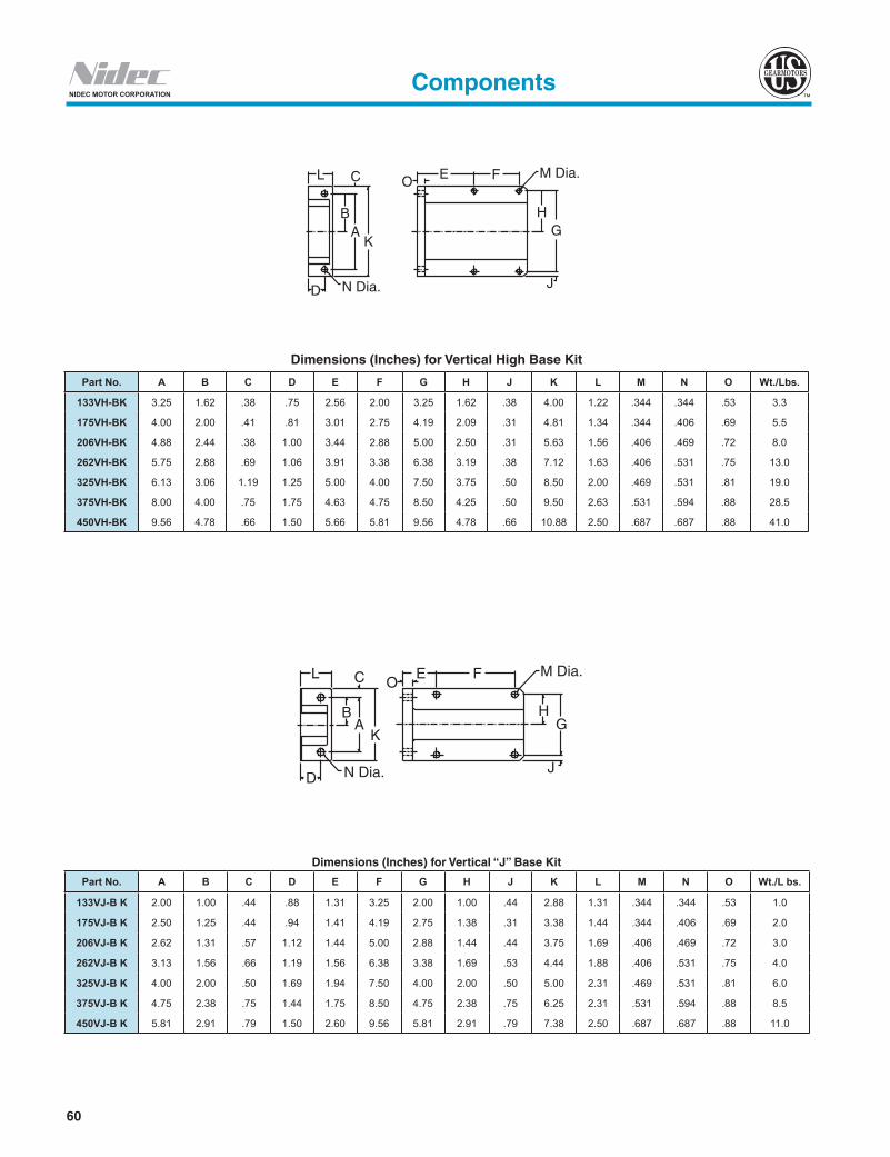
60
NIDEC MOTOR CORPORATION
D N Dia.
BA
K
L C O E F M Dia.
HG
J
D N Dia.
BA
K
L C OE F M Dia.
HG
J
Components
Dimensions (Inches) for Vertical “J” Base Kit
Part No. A B C D E F G H J K L M N O Wt./L bs.
133VJ-B K 2.00 1.00 .44 .88 1.31 3.25 2.00 1.00 .44 2.88 1.31 .344 .344 .53 1.0
175VJ-B K 2.50 1.25 .44 .94 1.41 4.19 2.75 1.38 .31 3.38 1.44 .344 .406 .69 2.0
206VJ-B K 2.62 1.31 .57 1.12 1.44 5.00 2.88 1.44 .44 3.75 1.69 .406 .469 .72 3.0
262VJ-B K 3.13 1.56 .66 1.19 1.56 6.38 3.38 1.69 .53 4.44 1.88 .406 .531 .75 4.0
325VJ-B K 4.00 2.00 .50 1.69 1.94 7.50 4.00 2.00 .50 5.00 2.31 .469 .531 .81 6.0
375VJ-B K 4.75 2.38 .75 1.44 1.75 8.50 4.75 2.38 .75 6.25 2.31 .531 .594 .88 8.5
450VJ-B K 5.81 2.91 .79 1.50 2.60 9.56 5.81 2.91 .79 7.38 2.50 .687 .687 .88 11.0
Dimensions (Inches) for Vertical High Base Kit
Part No. A B C D E F G H J K L M N O Wt./Lbs.
133VH-BK 3.25 1.62 .38 .75 2.56 2.00 3.25 1.62 .38 4.00 1.22 .344 .344 .53 3.3
175VH-BK 4.00 2.00 .41 .81 3.01 2.75 4.19 2.09 .31 4.81 1.34 .344 .406 .69 5.5
206VH-BK 4.88 2.44 .38 1.00 3.44 2.88 5.00 2.50 .31 5.63 1.56 .406 .469 .72 8.0
262VH-BK 5.75 2.88 .69 1.06 3.91 3.38 6.38 3.19 .38 7.12 1.63 .406 .531 .75 13.0
325VH-BK 6.13 3.06 1.19 1.25 5.00 4.00 7.50 3.75 .50 8.50 2.00 .469 .531 .81 19.0
375VH-BK 8.00 4.00 .75 1.75 4.63 4.75 8.50 4.25 .50 9.50 2.63 .531 .594 .88 28.5
450VH-BK 9.56 4.78 .66 1.50 5.66 5.81 9.56 4.78 .66 10.88 2.50 .687 .687 .88 41.0

61
US
G
earm
oto
r
NIDEC MOTOR CORPORATIONComponents
Dimensions (Inches) forOutput Plug-In Shaft Kit
Dimensions (Inches) for Cast Iron Output Flange Kit
Dimensions (Inches) for Base Kit/Riser Kit
CSq. Key
A
W
B
A
CD
FA
DØC
4 Holes
BA
B
R3
AC T
R1
L
H
R2D
CD
N
ØE BoltHole
ØU
K
Part No. A B C W Sq. Key
133H-SK 4.49 0.625 2.00 1.312 0.1875
175H-SK 4.92 0.875 1.91 1.375 0.1875
206H-SK 5.43 1.000 2.00 1.750 0.2500
262H-SK 6.21 1.125 2.50 2.000 0.2500
325H-SK 7.74 1.375 3.25 2.875 0.3125
Part No. CD A B C D E F
133H-CFK 1.33 4.50 2.25 0.344 5.00 5.88 3.00
175H-CFK 1.75 4.88 2.44 0.344 5.87 6.75 3.50
206H-CFK 2.06 5.75 2.88 0.406 7.00 7.87 3.75
262H-CFK 2.62 7.75 3.88 0.406 8.00 8.88 4.06
325H-CFK 3.25 9.00 4.50 0.531 10.00 11.00 5.25
Base Kit Riser Block Kit C.D. C-Face R1 R2 R3 T A B C D E K H L N U
133S-BK 133R-BK 1.33 56/140 1.89 0.24 1.07 0.53 5.38 4.20 4.38 3.31 0.38 6.50 1.72 5.35 4.00 0.62175S-BK 175R-BK 1.75 56/140 1.61 0.30 0.57 0.69 7.00 5.56 5.75 4.50 0.44 6.50 2.06 5.99 4.31 0.88206S-BK 206R-BK 2.06 56/140 1.42 0.20 0.57 0.72 7.70 5.76 6.38 4.69 0.50 6.50 2.28 6.23 4.72 1.00
262S-BK 262R-BK 2.62 56/140 180 2.40 1 59
0.340.59 0.72
0.75 9.26 6.50 8.00 5.25 0.56 6.50 9.00
2.93 8.22 5.63 1.13
325S-BK 325R-BK 3.25 56/140 180 1.87 1.25
00.82 0.65
0.88 11.14 7.76 9.50 6.13 0.56 6.50 9.00
3.50 8.63 7.06 1.38
375S-BK 375R-BK 3.75 56/140 180 1.77 1.2
0.08 0.530.94 12.00 8.63 10.38 7.00 0.59 6.76
9.003.88 9.27 7.75 1.63
450S-BK 450R-BK 4.50 140 180/215 2.27 1.83
0.71 0.281.12 13.88 9.33 12.12 7.63 0.66 6.76
9.004.50 10.83 8.44 1.63
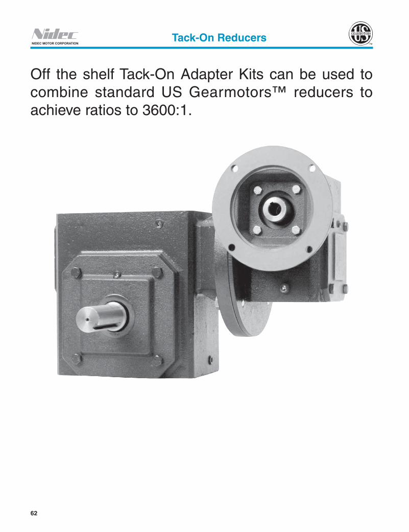
62
NIDEC MOTOR CORPORATIONTack-On Reducers
Off the shelf Tack-On Adapter Kits can be used to combine standard US Gearmotors™ reducers to achieve ratios to 3600:1.
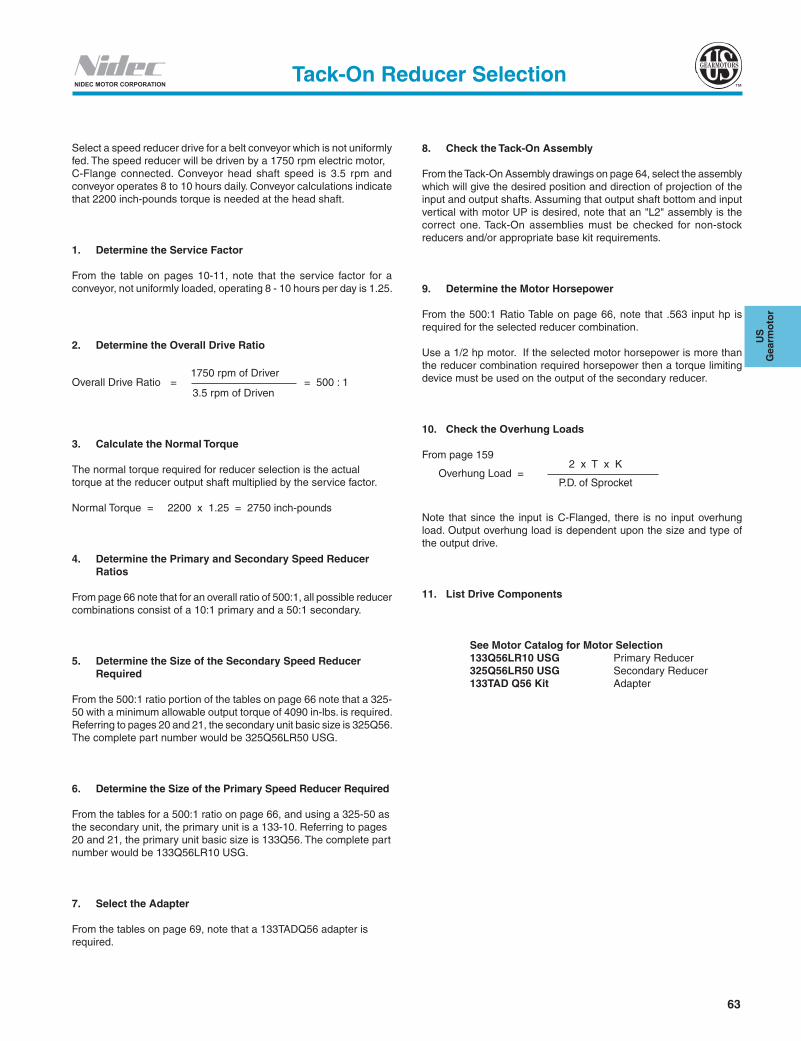
63
US
G
earm
oto
r
NIDEC MOTOR CORPORATIONTack-On Reducer Selection
Select a speed reducer drive for a belt conveyor which is not uniformly fed. The speed reducer will be driven by a 1750 rpm electric motor,C-Flange connected. Conveyor head shaft speed is 3.5 rpm and conveyor operates 8 to 10 hours daily. Conveyor calculations indicate that 2200 inch-pounds torque is needed at the head shaft.
1. Determine the Service Factor
From the table on pages 10-11, note that the service factor for a conveyor, not uniformly loaded, operating 8 - 10 hours per day is 1.25.
2. Determine the Overall Drive Ratio
1750 rpm of DriverOverall Drive Ratio = = 500 : 1 3.5 rpm of Driven
3. Calculate the Normal Torque
The normal torque required for reducer selection is the actual torque at the reducer output shaft multiplied by the service factor.
Normal Torque = 2200 x 1.25 = 2750 inch-pounds
4. Determine the Primary and Secondary Speed Reducer Ratios
From page 66 note that for an overall ratio of 500:1, all possible reducer combinations consist of a 10:1 primary and a 50:1 secondary.
5. Determine the Size of the Secondary Speed Reducer Required
From the 500:1 ratio portion of the tables on page 66 note that a 325-50 with a minimum allowable output torque of 4090 in-lbs. is required. Referring to pages 20 and 21, the secondary unit basic size is 325Q56. The complete part number would be 325Q56LR50 USG.
6. Determine the Size of the Primary Speed Reducer Required
From the tables for a 500:1 ratio on page 66, and using a 325-50 as the secondary unit, the primary unit is a 133-10. Referring to pages 20 and 21, the primary unit basic size is 133Q56. The complete part number would be 133Q56LR10 USG.
7. Select the Adapter
From the tables on page 69, note that a 133TADQ56 adapter is required.
8. Check the Tack-On Assembly
From the Tack-On Assembly drawings on page 64, select the assembly which will give the desired position and direction of projection of the input and output shafts. Assuming that output shaft bottom and input vertical with motor UP is desired, note that an "L2" assembly is the correct one. Tack-On assemblies must be checked for non-stock reducers and/or appropriate base kit requirements.
9. Determine the Motor Horsepower
From the 500:1 Ratio Table on page 66, note that .563 input hp is required for the selected reducer combination.
Use a 1/2 hp motor. If the selected motor horsepower is more than the reducer combination required horsepower then a torque limiting device must be used on the output of the secondary reducer.
10. Check the Overhung Loads
From page 159 2 x T x K Overhung Load = P.D. of Sprocket
Note that since the input is C-Flanged, there is no input overhung load. Output overhung load is dependent upon the size and type of the output drive.
11. List Drive Components
See Motor Catalog for Motor Selection 133Q56LR10 USG Primary Reducer 325Q56LR50 USG Secondary Reducer 133TAD Q56 Kit Adapter
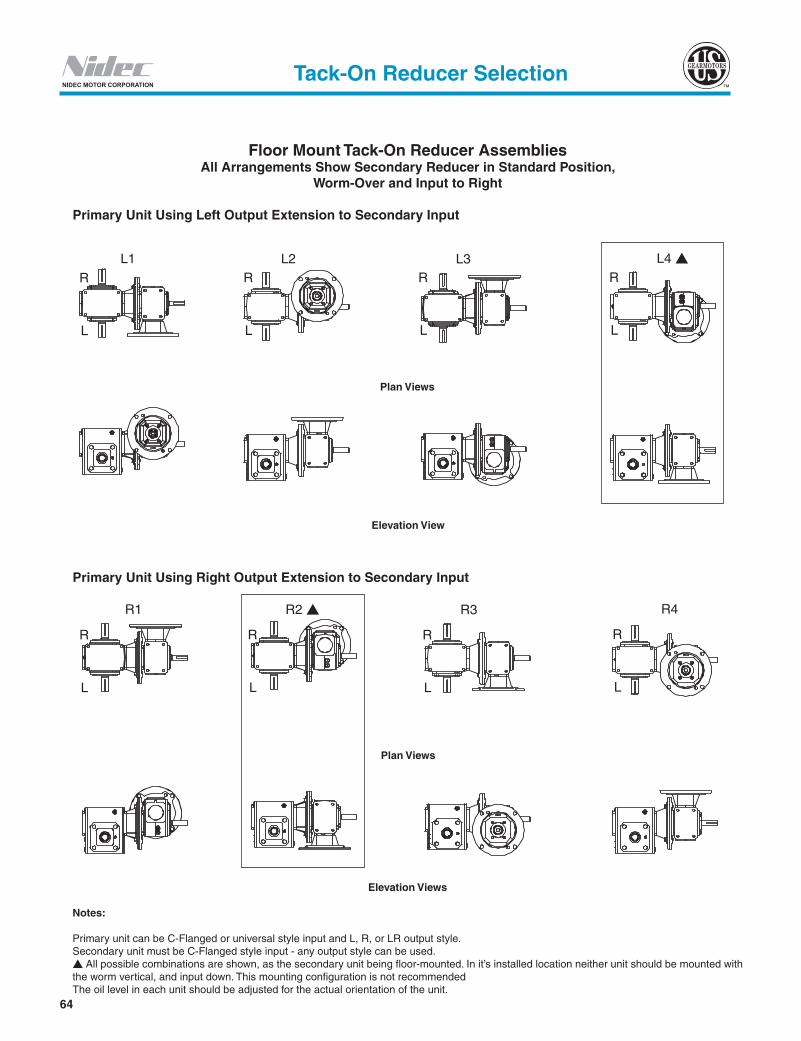
64
NIDEC MOTOR CORPORATION
L1
R1
R
RRRR
R R R
L
LLLL
L L L
L2
R2 �
L3
R3
L4 �
R4
Floor Mount Tack-On Reducer AssembliesAll Arrangements Show Secondary Reducer in Standard Position,
Worm-Over and Input to Right
Primary Unit Using Left Output Extension to Secondary Input
Elevation Views
Notes:
Primary unit can be C-Flanged or universal style input and L, R, or LR output style.Secondary unit must be C-Flanged style input - any output style can be used.s All possible combinations are shown, as the secondary unit being floor-mounted. In it’s installed location neither unit should be mounted with the worm vertical, and input down. This mounting configuration is not recommendedThe oil level in each unit should be adjusted for the actual orientation of the unit.
Tack-On Reducer Selection
Plan Views
Elevation View
Primary Unit Using Right Output Extension to Secondary Input
Plan Views

65
US
G
earm
oto
r
NIDEC MOTOR CORPORATION
Input Horsepower and Output Torque forCoupled US Gearmotors™ Single Reduction Worm Gear Speed Reducers
(1750 rpm Driver – 1.0 Service Factor)
Tack-On Reducer Assemblies
Reducers Primary Secondary
Primary Secondary Input hpOutput Torque
(In.-Lbs)25:1 Ratio - 70 rpm Output
133-5 133-5 0.372 221133-5 175-5 0.773 465
50:1 Ratio - 35 rpm Output133-5 133-10 0.229 263133-5 175-10 0.492 571133-5 206-10 0.813 947175-5 262-10 1.715 2039262-5 375-10 4.589 5636
75:1 Ratio - 23.3 rpm Output133-5 133-15 0.166 270133-5 175-15 0.355 589133-5 206-15 0.591 980133-5 262-15 1.255 2112175-5 262-15 1.243 2112262-5 375-15 3.580 6214325-5 450-15 5.649 9989
100:1 Ratio - 17.5 rpm Output133-5 133-20 0.140 284133-5 175-20 0.298 619133-5 206-20 0.494 1028133-5 262-20 1.042 2212175-5 262-20 1.032 2212175-5 325-20 2.063 4421262-5 375-20 2.756 6138262-5 450-20 4.380 9886133-10 133-10 0.124 269133-10 175-10 0.269 592133-10 206-10 0.449 988175-10 262-10 0.954 2151262-10 375-10 2.583 6059325-10 375-10 2.562 6059325-10 450-10 4.150 9893
150:1 Ratio - 11.67 rpm Output133-5 133-30 0.107 278133-5 175-30 0.211 605133-5 206-30 0.353 1006133-5 262-30 0.743 2167175-5 262-30 0.737 2167175-5 325-30 1.482 4359262-5 375-30 2.143 6386262-5 450-30 3.383 10283133-10 133-15 0.090 277133-10 175-15 0.194 607133-10 206-15 0.326 1018133-10 262-15 0.703 2216175-10 262-15 0.693 2216175-10 325-15 1.408 4514262-10 375-15 2.038 6692262-10 450-15 3.295 10936325-10 450-15 3.268 10936
200:1 Ratio - 8.75 rpm Output133-5 133-40 0.087 282133-5 175-40 0.182 616133-5 206-40 0.302 1022133-5 262-40 0.633 2202133-5 325-40 1.264 4399175-5 262-40 0.627 2202175-5 325-40 1.252 4399
Reducers Primary Secondary
Primary Secondary Input hpOutput Torque
(In.-Lbs)133-30 262-30 0.177 2345
400:1 Ratio - 4.37 rpm Output133-10 325-40 0.743 4697175-10 262-40 0.362 2313175-10 325-40 0.735 4697262-10 375-40 0.958 6535262-10 450-40 1.537 10692133-20 133-20 0.044 295133-20 175-20 0.093 650133-20 206-20 0.157 1089133-20 262-20 0.336 2382175-20 262-20 0.329 2382175-20 325-20 0.673 4872262-20 375-20 0.884 6784262-20 450-20 1.437 11171325-20 450-20 1.418 11171
Reducers Primary Secondary
Primary Secondary Input hpOutput Torque
(In.-Lbs)133-10 133-20 0.077 291133-10 175-20 0.165 640133-10 206-20 0.275 1068133-10 262-20 0.591 2324175-10 262-20 0.583 2324175-10 325-20 1.178 4720262-10 375-20 1.567 6567262-10 450-20 2.529 10732325-10 450-20 2.508 10732
225:1 Ratio - 7.78 rpm Output133-15 133-15 0.064 279133-15 175-15 0.138 614133-15 206-15 0.231 1029133-15 262-15 0.500 2251175-15 262-15 0.493 2251175-15 325-15 1.008 4606262-15 375-15 1.456 6853325-15 450-15 2.335 11249
250:1 Ratio - 7 rpm Output133-5 133-50 0.072 268133-5 175-50 0.149 583133-5 206-50 0.247 968133-5 262-50 0.518 2088133-5 325-50 1.037 4188175-5 262-50 0.512 2088175-5 325-50 1.027 4188262-5 375-50 1.332 5789262-5 450-50 2.096 9333
300:1 Ratio - 5.83 rpm Output133-5 175-60 0.125 546133-5 206-60 0.208 909133-5 262-60 0.434 1960133-5 325-60 0.872 3941175-5 262-60 0.429 1960175-5 325-60 0.863 3941262-5 450-60 1.721 8699
133-10 133-30 0.056 284133-10 175-30 0.119 622133-10 206-30 0.198 1044133-10 262-30 0.425 2273175-10 262-30 0.420 2273175-10 325-30 0.853 4637262-10 375-30 1.246 6866262-10 450-30 2.000 11230133-15 133-20 0.055 293133-15 175-20 0.118 646133-15 206-20 0.197 1082133-15 262-20 0.423 2362175-15 262-20 0.415 2362175-15 325-20 0.850 4821262-15 375-20 1.124 6718262-15 450-20 1.817 11029325-15 450-20 1.799 11029
400:1 Ratio - 4.37 rpm Output133-10 133-40 0.048 290133-10 175-40 0.104 635133-10 206-40 0.172 1062133-10 262-40 0.367 2313133-30 206-30 0.082 1069
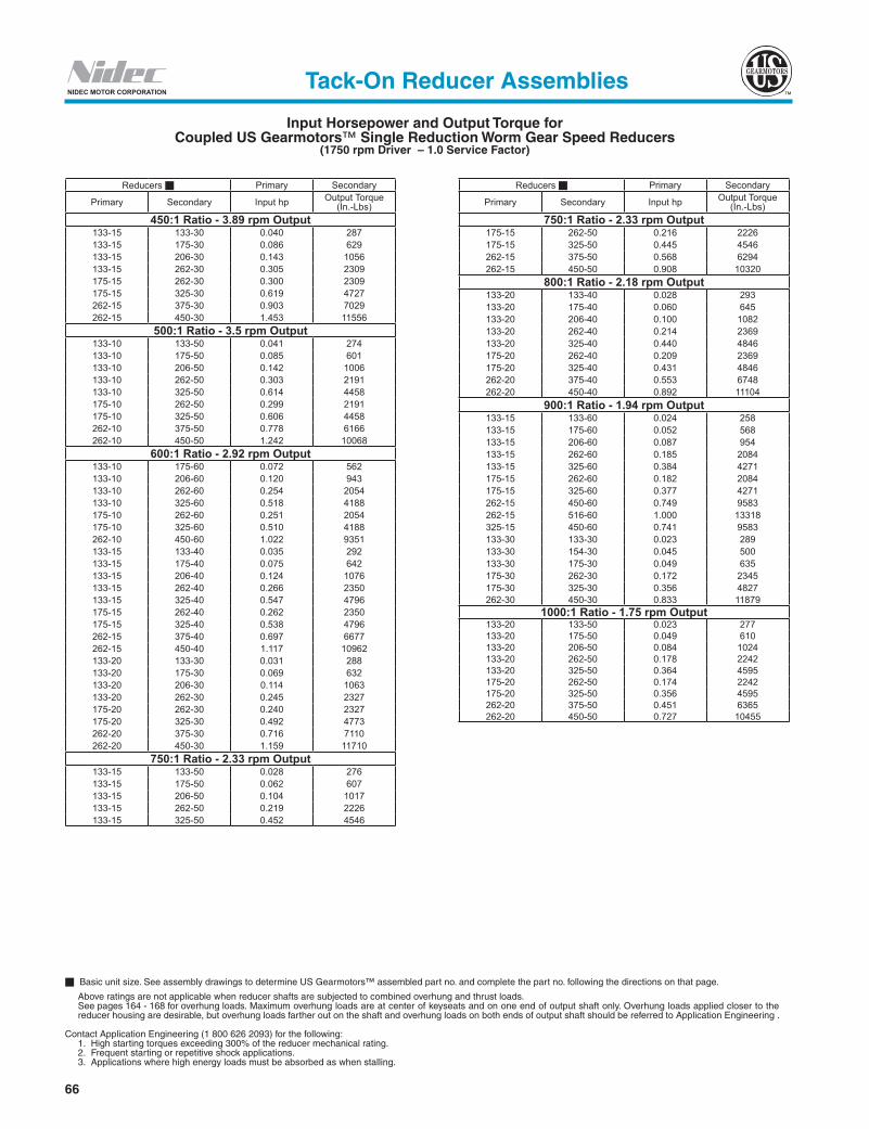
66
NIDEC MOTOR CORPORATION
Input Horsepower and Output Torque forCoupled US Gearmotors™ Single Reduction Worm Gear Speed Reducers
(1750 rpm Driver – 1.0 Service Factor)
Basic unit size. See assembly drawings to determine US Gearmotors™ assembled part no. and complete the part no. following the directions on that page.
Above ratings are not applicable when reducer shafts are subjected to combined overhung and thrust loads. See pages 164 - 168 for overhung loads. Maximum overhung loads are at center of keyseats and on one end of output shaft only. Overhung loads applied closer to the
reducer housing are desirable, but overhung loads farther out on the shaft and overhung loads on both ends of output shaft should be referred to Application Engineering .
Contact Application Engineering (1 800 626 2093) for the following: 1. High starting torques exceeding 300% of the reducer mechanical rating. 2. Frequent starting or repetitive shock applications. 3. Applications where high energy loads must be absorbed as when stalling.
Tack-On Reducer Assemblies
Reducers Primary Secondary
Primary Secondary Input hp Output Torque (In.-Lbs)
450:1 Ratio - 3.89 rpm Output133-15 133-30 0.040 287133-15 175-30 0.086 629133-15 206-30 0.143 1056133-15 262-30 0.305 2309175-15 262-30 0.300 2309175-15 325-30 0.619 4727262-15 375-30 0.903 7029262-15 450-30 1.453 11556
500:1 Ratio - 3.5 rpm Output133-10 133-50 0.041 274133-10 175-50 0.085 601133-10 206-50 0.142 1006133-10 262-50 0.303 2191133-10 325-50 0.614 4458175-10 262-50 0.299 2191175-10 325-50 0.606 4458262-10 375-50 0.778 6166262-10 450-50 1.242 10068
600:1 Ratio - 2.92 rpm Output133-10 175-60 0.072 562133-10 206-60 0.120 943133-10 262-60 0.254 2054133-10 325-60 0.518 4188175-10 262-60 0.251 2054175-10 325-60 0.510 4188262-10 450-60 1.022 9351133-15 133-40 0.035 292133-15 175-40 0.075 642133-15 206-40 0.124 1076133-15 262-40 0.266 2350133-15 325-40 0.547 4796175-15 262-40 0.262 2350175-15 325-40 0.538 4796262-15 375-40 0.697 6677262-15 450-40 1.117 10962133-20 133-30 0.031 288133-20 175-30 0.069 632133-20 206-30 0.114 1063133-20 262-30 0.245 2327175-20 262-30 0.240 2327175-20 325-30 0.492 4773262-20 375-30 0.716 7110262-20 450-30 1.159 11710
750:1 Ratio - 2.33 rpm Output133-15 133-50 0.028 276133-15 175-50 0.062 607133-15 206-50 0.104 1017133-15 262-50 0.219 2226133-15 325-50 0.452 4546
Reducers Primary Secondary
Primary Secondary Input hp Output Torque (In.-Lbs)
750:1 Ratio - 2.33 rpm Output175-15 262-50 0.216 2226175-15 325-50 0.445 4546262-15 375-50 0.568 6294262-15 450-50 0.908 10320
800:1 Ratio - 2.18 rpm Output133-20 133-40 0.028 293133-20 175-40 0.060 645133-20 206-40 0.100 1082133-20 262-40 0.214 2369133-20 325-40 0.440 4846175-20 262-40 0.209 2369175-20 325-40 0.431 4846262-20 375-40 0.553 6748262-20 450-40 0.892 11104
900:1 Ratio - 1.94 rpm Output133-15 133-60 0.024 258133-15 175-60 0.052 568133-15 206-60 0.087 954133-15 262-60 0.185 2084133-15 325-60 0.384 4271175-15 262-60 0.182 2084175-15 325-60 0.377 4271262-15 450-60 0.749 9583262-15 516-60 1.000 13318325-15 450-60 0.741 9583133-30 133-30 0.023 289133-30 154-30 0.045 500133-30 175-30 0.049 635175-30 262-30 0.172 2345175-30 325-30 0.356 4827262-30 450-30 0.833 11879
1000:1 Ratio - 1.75 rpm Output133-20 133-50 0.023 277133-20 175-50 0.049 610133-20 206-50 0.084 1024133-20 262-50 0.178 2242133-20 325-50 0.364 4595175-20 262-50 0.174 2242175-20 325-50 0.356 4595262-20 375-50 0.451 6365262-20 450-50 0.727 10455

67
US
G
earm
oto
r
NIDEC MOTOR CORPORATION
Basic unit size. See assembly drawings to determine US Gearmotors™ assembled part no. and complete the part no. following the directions on that page.
Above ratings are not applicable when reducer shafts are subjected to combined overhung and thrust loads. See pages 164 - 168 for overhung loads. Maximum overhung loads are at center of keyseats and on one end of output shaft only. Overhung loads applied closer to the reducer
housing are desirable, but overhung loads farther out on the shaft and overhung loads on both ends of output shaft should be referred to Application Engineering .
Contact Application Engineering (1 800 626 2093) for the following: 1. High starting torques exceeding 300% of the reducer mechanical rating. 2. Frequent starting or repetitive shock applications. 3. Applications where high energy loads must be absorbed as when stalling.
Input Horsepower and Output Torque forCoupled US Gearmotors™ Single Reduction Worm Gear Speed Reducers
(1750 rpm Driver – 1.0 Service Factor)
Tack-On Reducer Assemblies
Reducers Primary Secondary
Primary Secondary Input hp Output Torque (In.-Lbs)
133-40 175-60 0.024 576133-40 206-60 0.041 967133-40 262-60 0.093 2124133-40 325-60 0.192 4379175-40 262-60 0.089 2124175-40 325-60 0.184 4379262-40 450-60 0.356 9861325-40 450-60 0.348 9861
2500:1 Ratio - .70 rpm Output133-50 133-50 0.011 279133-50 175-50 0.026 615133-50 206-50 0.043 1034133-50 262-50 0.092 2272133-50 325-50 0.192 4682175-50 262-50 0.087 2272175-50 325-50 0.184 4682262-50 375-50 0.226 6482262-50 450-50 0.364 10685
3000:1 Ratio - .58 rpm Output133-50 175-60 0.022 576133-50 206-60 0.037 970133-50 262-50 0.078 2128133-50 325-60 0.165 4393175-50 262-50 0.075 2128175-50 325-60 0.158 4393262-50 450-60 0.302 9892325-50 450-60 0.293 9892
3600:1 Ratio - .49 rpm Output175-60 262-60 0.046 2276175-60 325-60 0.140 4399262-60 450-60 0.264 9922
Reducers Primary Secondary
Primary Secondary Input hp Output Torque (In.-Lbs)
1200:1 Ratio - 1.46 rpm Output133-20 175-60 0.041 571133-20 206-60 0.071 960133-20 262-60 0.150 2102133-20 325-60 0.308 4311175-20 262-60 0.147 2102175-20 325-60 0.302 4311262-20 450-60 0.600 9691325-20 450-60 0.592 9691133-30 133-40 0.020 294133-30 175-40 0.043 649133-30 206-40 0.074 1090133-30 262-40 0.157 2388133-30 325-40 0.323 4897175-30 262-40 0.153 2388175-30 325-40 0.314 4897262-30 375-40 0.399 6823262-30 450-40 0.644 11246
1500:1 Ratio - 1.17 rpm Output133-30 133-50 0.016 245133-30 175-50 0.036 613133-30 206-50 0.061 1030133-30 262-50 0.130 2260133-30 325-50 0.268 4644175-30 262-50 0.125 2260175-30 325-50 0.261 4644262-30 375-50 0.327 6430262-30 450-50 0.525 10582325-30 375-50 0.320 6430325-30 450-50 0.517 10582
1600:1 Ratio -1.09 rpm Output133-40 133-40 0.017 294133-40 175-40 0.037 651133-40 206-40 0.061 1092133-40 262-40 0.131 2399133-40 325-40 0.270 4921175-40 262-40 0.125 2399175-40 325-40 0.261 4921262-40 375-40 0.326 6857262-40 450-40 0.525 11316
1800:1 Ratio - .97 rpm Output133-30 175-60 0.032 573133-30 206-60 0.051 966133-30 262-60 0.111 2118133-30 325-60 0.229 4358175-30 262-60 0.108 2118175-30 325-60 0.222 4358262-30 375-60 0.271 5966262-30 450-60 0.435 9811
2000:1 Ratio - .87 rpm Output133-40 133-50 0.014 279133-40 175-50 0.029 615133-40 206-50 0.050 1032133-40 262-50 0.108 2268133-40 325-50 0.225 4666175-40 262-50 0.104 2268175-40 325-50 0.217 4666262-40 375-50 0.267 6460262-40 450-50 0.429 10645
2400:1 Ratio - .73 rpm Output
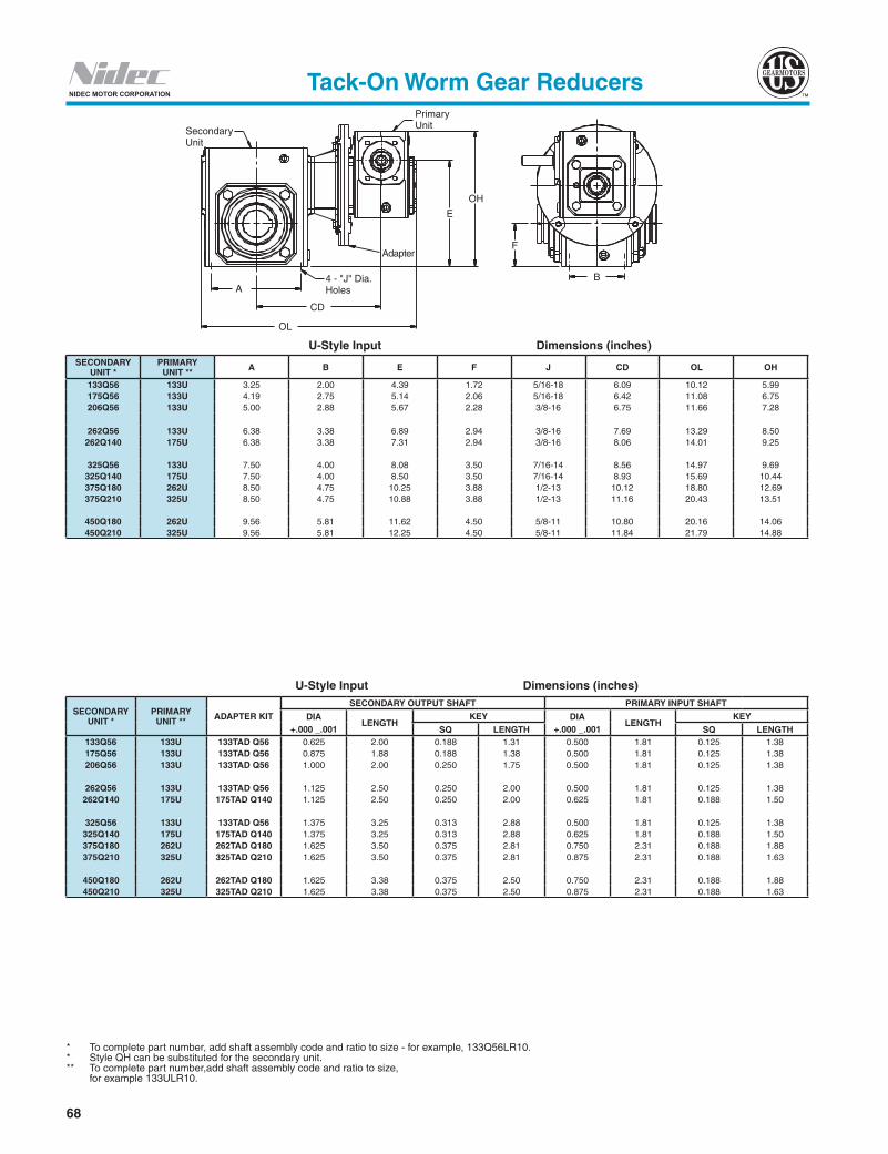
68
NIDEC MOTOR CORPORATION
SecondaryUnit
PrimaryUnit
OH
E
OL
CD
4 - "J" Dia.Holes
Adapter
A
F
B
U-Style Input Dimensions (inches)
U-Style Input Dimensions (inches)
Tack-On Worm Gear Reducers
* To complete part number, add shaft assembly code and ratio to size - for example, 133Q56LR10. * Style QH can be substituted for the secondary unit.** To complete part number,add shaft assembly code and ratio to size, for example 133ULR10.
SECONDARY UNIT *
PRIMARY UNIT ** A B E F J CD OL OH
133Q56 133U 3.25 2.00 4.39 1.72 5/16-18 6.09 10.12 5.99175Q56 133U 4.19 2.75 5.14 2.06 5/16-18 6.42 11.08 6.75206Q56 133U 5.00 2.88 5.67 2.28 3/8-16 6.75 11.66 7.28
262Q56 133U 6.38 3.38 6.89 2.94 3/8-16 7.69 13.29 8.50262Q140 175U 6.38 3.38 7.31 2.94 3/8-16 8.06 14.01 9.25
325Q56 133U 7.50 4.00 8.08 3.50 7/16-14 8.56 14.97 9.69325Q140 175U 7.50 4.00 8.50 3.50 7/16-14 8.93 15.69 10.44375Q180 262U 8.50 4.75 10.25 3.88 1/2-13 10.12 18.80 12.69375Q210 325U 8.50 4.75 10.88 3.88 1/2-13 11.16 20.43 13.51
450Q180 262U 9.56 5.81 11.62 4.50 5/8-11 10.80 20.16 14.06450Q210 325U 9.56 5.81 12.25 4.50 5/8-11 11.84 21.79 14.88
SECONDARY UNIT *
PRIMARY UNIT ** ADAPTER KIT
SECONDARY OUTPUT SHAFT PRIMARY INPUT SHAFT
DIA +.000 _.001
LENGTHKEY DIA
+.000 _.001LENGTH
KEY
SQ LENGTH SQ LENGTH133Q56 133U 133TAD Q56 0.625 2.00 0.188 1.31 0.500 1.81 0.125 1.38175Q56 133U 133TAD Q56 0.875 1.88 0.188 1.38 0.500 1.81 0.125 1.38206Q56 133U 133TAD Q56 1.000 2.00 0.250 1.75 0.500 1.81 0.125 1.38
262Q56 133U 133TAD Q56 1.125 2.50 0.250 2.00 0.500 1.81 0.125 1.38262Q140 175U 175TAD Q140 1.125 2.50 0.250 2.00 0.625 1.81 0.188 1.50
325Q56 133U 133TAD Q56 1.375 3.25 0.313 2.88 0.500 1.81 0.125 1.38325Q140 175U 175TAD Q140 1.375 3.25 0.313 2.88 0.625 1.81 0.188 1.50375Q180 262U 262TAD Q180 1.625 3.50 0.375 2.81 0.750 2.31 0.188 1.88375Q210 325U 325TAD Q210 1.625 3.50 0.375 2.81 0.875 2.31 0.188 1.63
450Q180 262U 262TAD Q180 1.625 3.38 0.375 2.50 0.750 2.31 0.188 1.88450Q210 325U 325TAD Q210 1.625 3.38 0.375 2.50 0.875 2.31 0.188 1.63
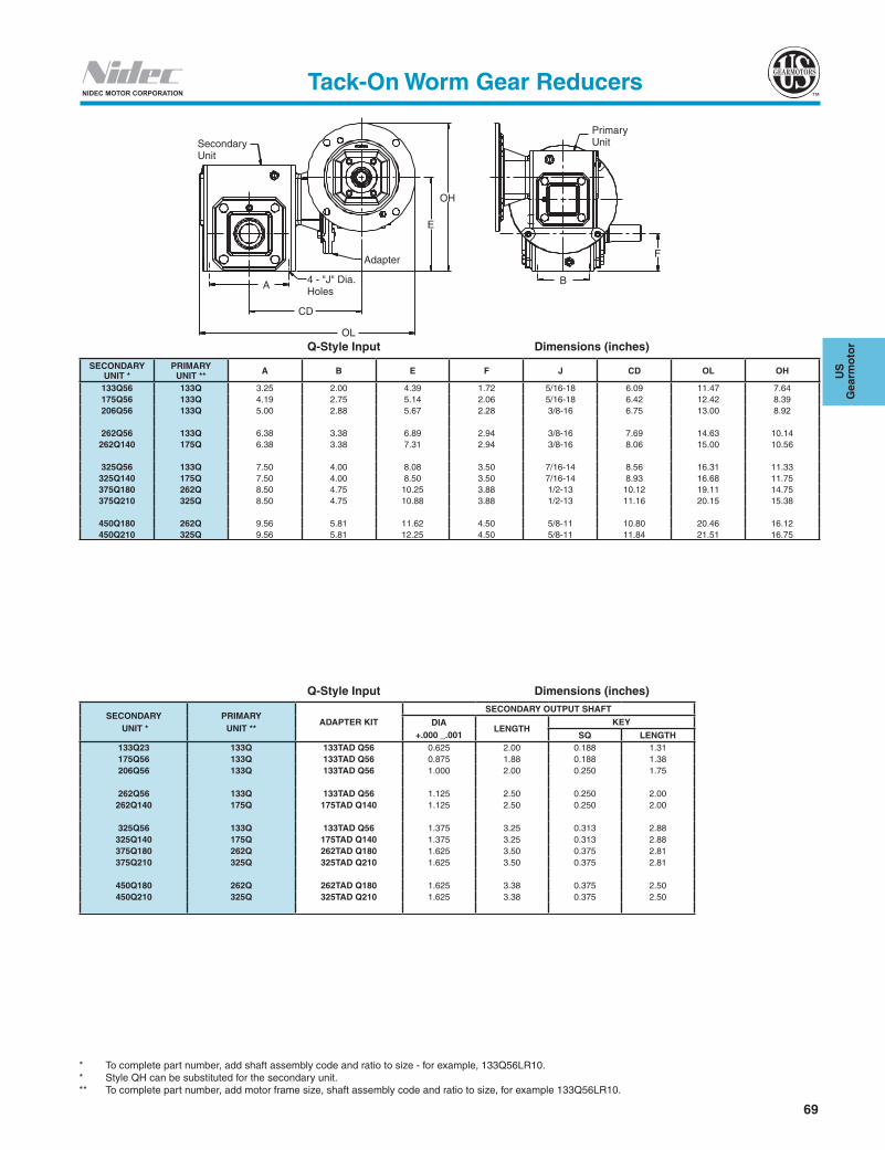
69
US
G
earm
oto
r
NIDEC MOTOR CORPORATION
SecondaryUnit
OL
4 - "J" Dia.Holes
CD
Adapter
B
F
E
OH
A
PrimaryUnit
Tack-On Worm Gear Reducers
Q-Style Input Dimensions (inches)
* To complete part number, add shaft assembly code and ratio to size - for example, 133Q56LR10. * Style QH can be substituted for the secondary unit. ** To complete part number, add motor frame size, shaft assembly code and ratio to size, for example 133Q56LR10.
Q-Style Input Dimensions (inches)
SECONDARY UNIT *
PRIMARY UNIT ** A B E F J CD OL OH
133Q56 133Q 3.25 2.00 4.39 1.72 5/16-18 6.09 11.47 7.64175Q56 133Q 4.19 2.75 5.14 2.06 5/16-18 6.42 12.42 8.39206Q56 133Q 5.00 2.88 5.67 2.28 3/8-16 6.75 13.00 8.92
262Q56 133Q 6.38 3.38 6.89 2.94 3/8-16 7.69 14.63 10.14262Q140 175Q 6.38 3.38 7.31 2.94 3/8-16 8.06 15.00 10.56
325Q56 133Q 7.50 4.00 8.08 3.50 7/16-14 8.56 16.31 11.33325Q140 175Q 7.50 4.00 8.50 3.50 7/16-14 8.93 16.68 11.75375Q180 262Q 8.50 4.75 10.25 3.88 1/2-13 10.12 19.11 14.75375Q210 325Q 8.50 4.75 10.88 3.88 1/2-13 11.16 20.15 15.38
450Q180 262Q 9.56 5.81 11.62 4.50 5/8-11 10.80 20.46 16.12450Q210 325Q 9.56 5.81 12.25 4.50 5/8-11 11.84 21.51 16.75
SECONDARY UNIT *
PRIMARY UNIT **
ADAPTER KIT
SECONDARY OUTPUT SHAFT
DIA +.000 _.001
LENGTHKEY
SQ LENGTH133Q23 133Q 133TAD Q56 0.625 2.00 0.188 1.31175Q56 133Q 133TAD Q56 0.875 1.88 0.188 1.38206Q56 133Q 133TAD Q56 1.000 2.00 0.250 1.75
262Q56 133Q 133TAD Q56 1.125 2.50 0.250 2.00262Q140 175Q 175TAD Q140 1.125 2.50 0.250 2.00
325Q56 133Q 133TAD Q56 1.375 3.25 0.313 2.88325Q140 175Q 175TAD Q140 1.375 3.25 0.313 2.88375Q180 262Q 262TAD Q180 1.625 3.50 0.375 2.81375Q210 325Q 325TAD Q210 1.625 3.50 0.375 2.81
450Q180 262Q 262TAD Q180 1.625 3.38 0.375 2.50450Q210 325Q 325TAD Q210 1.625 3.38 0.375 2.50