u.s. environmental protection agency questionnaire for … · 2015-06-19 · u.s. environmental...
TRANSCRIPT

Attach Address Label
U.S. ENVIRONMENTAL PROTECTION AGENCY
QUESTIONNAIRE FOR THE STEAM ELECTRIC POWER GENERATING EFFLUENT GUIDELINES
Form Approved OMB Control No. 2040-0281 Approval Expires 05/31/2013
The public reporting and recordkeeping burden for this collection of information is estimated to average 168
hours per response. Send comments on the Agency's need for this information, the accuracy of the provided burden estimates, and any suggested methods for minimizing respondent burden, including through the use of automated collection techniques to the Director, Collection Strategies Division, U.S. Environmental Protection Agency (2822T), 1200 Pennsylvania Ave., NW, Washington, D.C. 20460. Include the OMB control number in any correspondence. Do not send the completed survey to this address.

Steam Electric Questionnaire General Instructions
i Approved: May 20, 2010
INTRODUCTION The U.S. Environmental Protection Agency (EPA) is collecting data about steam electric power generating plants as part of its effort to review and revise the Steam Electric Power Generating effluent limitations guidelines and standards (40 CFR Part 423). This questionnaire solicits information from plants that generate steam for the primary purpose of producing electricity. This survey effort is being conducted under the authority of Section 308 of the Clean Water Act (Federal Water Pollution Control Act, 33 U.S.C. Section 1318). All plants that receive this questionnaire must respond within 90 days of receipt. Failure to respond, late filing, or failure to comply with the instructions may result in fines, civil penalties, and other sanctions, as provided by law. BACKGROUND ON EFFLUENT LIMITATIONS GUIDELINES AND STANDARDS (ELGs) The Agency recently completed a multi-year study of the Steam Electric Power Generating industry and, based on the results, has determined that revising the current effluent guidelines is warranted. EPA’s decision to revise the current effluent guidelines is largely driven by the high level of toxic-weighted pollutant discharges from power plants and the expectation that these discharges will increase significantly in the next few years as new air pollution controls are installed. Over the course of the study EPA has identified technologies that are available to significantly reduce these pollutant discharges. Effluent guidelines (i.e., effluent limitations guidelines and standards) are developed pursuant to the Clean Water Act and are restrictions that may be applied to industrial discharges. EPA develops effluent guidelines on an industry-by-industry basis using information collected during the rulemaking process. OVERVIEW OF THE QUESTIONNAIRE The questionnaire is divided into the following parts:
PART A: STEAM ELECTRIC POWER PLANT OPERATIONS; PART B: FLUE GAS DESULFURIZATION (FGD) SYSTEMS; PART C: ASH HANDLING; PART D: POND/IMPOUNDMENT SYSTEMS AND OTHER WASTEWATER TREATMENT
OPERATIONS; PART E: WASTES FROM CLEANING METAL PROCESS EQUIPMENT; PART F: MANAGEMENT PRACTICES FOR PONDS/IMPOUNDMENTS AND LANDFILLS; PART G: LEACHATE SAMPLING DATA FOR PONDS/IMPOUNDMENTS AND LANDFILLS; PART H: NUCLEAR POWER GENERATION; AND PART I: ECONOMIC AND FINANCIAL DATA.
The questionnaire consists of multiple sections which have been tailored to address specific processes, specific data needs, or types of power plants. Part A of the questionnaire collects general plant information and selected technical information about the plant processes and the electric generating units. Additional sections of the questionnaire are designed to collect economic data and to collect technical information on flue gas desulfurization (FGD) wastewater, ash handling, metal cleaning operations, wastewater treatment, surface impoundment and landfill operations, and nuclear operations. One section of the questionnaire requires certain power plants to collect and analyze samples of leachate from surface impoundments and landfills containing coal combustion residues. A detailed table of contents listing the specific topics of information requested is located at the beginning of each part of the questionnaire. Respondents are required to complete and submit an electronic version of the questionnaire. Parts A and I of the questionnaire are provided to all questionnaire recipients; the remaining parts will be sent to discrete subpopulations of questionnaire recipients: coal-fired, petroleum coke-fired, oil-fired, gas-fired, and nuclear plants. Respondents must read the cover letter received with the questionnaire to determine which parts of the questionnaire they have been given to complete. In addition, respondents must read the instructions preceding each part to determine whether that part needs to be completed for their plant.

Steam Electric Questionnaire General Instructions
ii Approved: May 20, 2010
EPA will use the technical data collected in this survey to determine rates and characteristics of wastewater generated by the steam electric industry, to develop treatment technology options, and to evaluate incremental costs and benefits associated with different regulatory options. For more information on this rulemaking, see http://www.epa.gov/guide/steam/. For some questions, EPA requests information for calendar year 2009. However, some questions request information regarding past, present, or future (i.e., “planned”) plant operations. COMPLETION OF THE QUESTIONNAIRE Each part should be completed by personnel knowledgeable about the information requested. All plants must have the corporate official or designee responsible for directing or supervising the response to the questionnaire sign the Certification Statement on page vii to verify and validate the information provided. Different people may complete each part of the questionnaire. See the instructions below for completing the electronic questionnaire. Keep a copy of the completed questionnaire, including attachments. EPA will review the information submitted and may request your cooperation in answering follow-up questions, if necessary, to complete analyses. ELECTRONIC VERSION OF THE QUESTIONNAIRE EPA has distributed the questionnaire in electronic format, and respondents are required to submit the completed questionnaire to EPA in electronic format. The electronic questionnaire is made up of a series of Microsoft Excel workbooks. The electronic questionnaire has been developed to meet the 1998 Government Paperwork Elimination Act (GPEA). EPA designed the questionnaire to include many burden-reducing features. The questionnaire was designed in modular fashion to reduce respondent burden by making it easier for them to separate and distribute questionnaire parts to various plant and corporate staff. The CD that will be distributed to questionnaire recipients includes both the electronic-fillable questionnaire and a pdf-file that can be printed out and used as a working copy. Copies of selected sections can be made when needed and selected sections of the working copy distributed to the appropriate staff. The electronic questionnaire format allows facilities to electronically generate the required number of copies of each section by selecting the copy button located at the beginning of the section that may require multiple copies. Once the questionnaire is complete, save each Part file as a Microsoft Excel workbook to a CD or DVD depending on the size required to hold your completed questionnaire files and any additional supporting documents. EPA prefers that diagrams and reports or documents submitted with the questionnaire also be saved and submitted on the CD/DVD, if possible. Please either save a pdf version of the signed certification statement on page vii to the CD/DVD or return a hardcopy of the signed certification statement. The certification statement, questionnaire response, and supporting documents must be mailed to the second address listed on page v. Do not submit the completed questionnaire and associated documents via e-mail, because the document may contain confidential business information. HOW TO NAVIGATE THE QUESTIONNAIRE EPA formatted the electronic-fillable questionnaire in Microsoft Excel. Each part of the questionnaire is its own Excel workbook file that consists of multiple sections and subsections, which are each represented by separate tabs (or worksheets) in the workbook. Some parts of the questionnaire contain more sections than others. Make sure to read through each section and complete every tab within each part. Also make sure to completely scroll through every section so that every relevant question is answered. An example of the questionnaire format is located below:

Steam Electric Questionnaire General Instructions
iii Approved: May 20, 2010
Opening the Electronic Form 1. Download each file from the provided CD onto your computer's hard drive. 2. Launch Microsoft® Excel, then select Tools > Macro > Security. In the Security Level tab, select
"Medium." (Note: This security level allows you to run essential macros contained in the electronic form.)
3. As you open each part of the questionnaire, a security window should appear regarding macros.
Select "Enable Macros" and then "OK." If the window does not appear, close the file and repeat step 2 above.
Filling out the Electronic Form Within the electronic form, yellow highlights indicate blank fields that you must complete. Use your mouse or tab key to navigate between blanks. Type in your response, then Tab to the next field. Every question is formatted to collect the most consistent answers between each respondent. The format of every question is dictated by the type of information requested, summarized below:
If a question requires a descriptive or variable response, the respondent must provide a written explanation in the highlighted yellow response box located directly below the question.
If a question instructs the respondent to “check all that apply,” the respondent must select all the
square-shaped check boxes that correspond to the applicable response options.

Steam Electric Questionnaire General Instructions
iv Approved: May 20, 2010
If a question instructs the respondent to choose only one answer, the response options are
formatted in one of two ways:
o If a response is formatted as a drop-down-box, click on the arrow and scroll down the list to find and select the most applicable option.
o If a response is formatted as a list of options with corresponding circles, select the circle with the most applicable option.
If any question does not provide an applicable response option, select “other” and provide a
written response in the highlighted yellow response box adjacent to the response options or on the comments page for that Part.
Each plant is assigned a plant ID that is listed on the cover letter you received with your questionnaire CD. You will need to enter the plant name and plant ID in the “Plant Name” and “Plant ID” header fields in the table of contents for each part, after which all header fields throughout the rest of the part will automatically populate. An example of the table of contents is located below:

Steam Electric Questionnaire General Instructions
v Approved: May 20, 2010
QUESTIONNAIRE ASSISTANCE If you have any questions regarding the completion of this questionnaire, you can request assistance using EPA’s e-mail and telephone helplines provided below. WHEN TO RETURN THE QUESTIONNAIRE The response to all portions of the questionnaire except Part G is due 90 days after receipt. Part G is due 120 days after receipt. If you wish to request an extension, you must do so in writing within 21 days of receipt of this questionnaire. Written requests may be e-mailed (preferred) or mailed to:
Jezebele Alicea USEPA Headquarters Ariel Rios Building 1200 Pennsylvania Avenue, NW Mail Code: 4303T Washington, DC 20460 [email protected] 202-566-1755
Extension requests will be evaluated on a case-by-case basis. Submittal of an extension request to EPA does not alter the due date of your questionnaire unless and until EPA agrees to the extension and establishes a new date. WHERE TO RETURN THE QUESTIONNAIRE After completing the questionnaire and certifying the information that it contains, use the enclosed mailing label to mail the completed questionnaire to:
U.S. Environmental Protection Agency Questionnaire for the Steam Electric Power Generating Effluent Guidelines c/o Eastern Research Group, Inc. 14555 Avion Parkway, Suite 200 Chantilly, VA 20151-1102
EPA Steam Electric Questionnaire Help Lines Assistance for the Technical Questionnaire (Parts A through H) Eastern Research Group, Inc. ....................................................Local: 703-633-1696 or Toll-free: 1-877-353-7560 Internet Electronic Mailing Address (E-mail) ............................................................................ [email protected] Assistance for the Economic and Financial Questionnaire (Part I) Abt Associates, Inc. ....................................................................Local: 617-520-2336 or Toll-free: 1-877-344-9540 Internet Electronic Mailing Address (E-mail) ................................................................ [email protected]

Steam Electric Questionnaire General Instructions
vi Approved: May 20, 2010
CONFIDENTIAL BUSINESS INFORMATION If no business confidentiality claim accompanies the information when it is received by EPA, EPA may make the information available to the public without further notice. Regulations governing the confidentiality of business information are contained in the Code of Federal Regulations (CFR) at Title 40 Part 2, Subpart B. You may assert a business confidentiality claim covering part or all of the information you submit, other than effluent data and information or data that is otherwise publicly available, as described in 40 CFR 2.203(b):
“(b) Method and time of asserting business confidentiality claim. A business which is submitting information to EPA may assert a business confidentiality claim covering the information by placing on (or attaching to) the information, at the time it is submitted to EPA, a cover sheet, stamped or typed legend, or other suitable form of notice complying language such as ‘trade secret,’ ‘proprietary,’ or ‘company confidential.’ Allegedly confidential portions of otherwise nonconfidential documents should be clearly identified by the business, and may be submitted separately to facilitate identification and handling by EPA. If the business desires confidential treatment only until a certain date or until the occurrence of a certain event, the notice should so state.”
You may claim as confidential all information included in the response to a question by checking the Confidential Business Information (CBI) box next to the question number. Note that plant effluent data are not eligible for confidential treatment, pursuant to Section 308(b) of the Clean Water Act. In addition, information that is publicly-available should not be claimed confidential. If you claim any questionnaire response or other data as CBI, other than by checking the box, you must specify the portion of the response or document for which you assert a claim of confidentiality by reference to page numbers, paragraphs, and lines, or specify the entire response or document. Additionally, for questions where you checked the box to indicate that the response includes CBI but only intend for a portion of the response to be claimed CBI, please specify what data are CBI. This information must be provided as part of the submission of the completed questionnaire. Note that EPA will review the information submitted and may request your cooperation in providing information to identify and justify the basis of your CBI claim. If you believe that facts and documents necessary to substantiate confidentiality are themselves confidential, please identify them as such so that EPA may maintain their confidentiality pursuant to 40 CFR Part 2, Subpart B. Information covered by a claim of confidentiality will be disclosed by EPA only to the extent of, and by means of, the procedures set forth in 40 CFR Part 2, Subpart B. In general, submitted information protected by a business confidentiality claim may be disclosed to other employees, officers, or authorized representatives of the United States concerned with implementing the Clean Water Act. Information covered by a claim of confidentiality will be made available to EPA contractors to enable the contractors to perform the work required by their contracts with EPA. All EPA contracts provide that contractor employees use the information only for the purpose of performing the work required by their contracts and will not disclose any CBI to anyone other than EPA without prior written approval from each affected business or from EPA's legal office.

Steam Electric Questionnaire General Instructions
vii Approved: May 20, 2010
Plant Name:
Plant ID:
CERTIFICATION STATEMENT The individual responsible for directing or supervising the preparation of the questionnaire must read and sign the Certification Statement listed below. The certifying official must be a responsible corporate official or his/her authorized representative. Certification Statement I certify under penalty of law that the attached questionnaire was prepared under my direction or supervision and that qualified personnel properly gathered and evaluated the information submitted. The information submitted is, to the best of my knowledge and belief, accurate and complete. In those cases where we did not possess the requested information for questions applicable to our company, we provided best estimates. We have to the best of our ability indicated what we believe to be company confidential business information as defined under 40 CFR Part 2, Subpart B. We understand that we may be required at a later time to justify our claim in detail with respect to each item claimed confidential. I am aware that there are significant penalties for submitting false information, including the possibility of fines and imprisonment as explained in Section 308 of the Clean Water Act. Signature of Certifying Official Date ( ) Printed Name of Certifying Official Telephone Number of Certifying Official
Title of Certifying Official Company Name

viii Approved: May 20, 2010
INSTRUCTIONS FOR COMPLETING THE QUESTIONNAIRE Read all question-specific instructions (throughout the questionnaire) and definitions of key terms in the questionnaire glossary file. Throughout the questionnaire, key terms are in italics. Refer to the code tables located at the end of the each part if prompted to enter a code or complete a block diagram. Acronyms and measurement units are defined in the Acronyms list at the end of the general instructions. Enter the Plant ID in every part of the questionnaire. You will find your Plant ID in the cover letter you received with your questionnaire. When completing the electronic form, note the following: When you enter your plant name and plant ID in the “Plant Name” and “Plant ID” header fields in the table of contents for each part, all header fields throughout the rest of the part will automatically populate. Not all questions will be applicable to every company or plant. EPA prepared the questionnaire to be applicable to a variety of plants; therefore, not all of the questions will apply to every company or plant. Complete each relevant item in the questionnaire. Mark responses for each question. Fill in the appropriate response(s) to each question. Answer the questions in sequence unless you are directed to skip. If you are directed to skip to another section, click on the “Skip to Section X” colored hyperlink, which will direct you to the next appropriate section. Do not leave any entry blank. If the answer is zero, enter “0". If a question is not applicable to your company or plant, enter or select “NA.” Best engineering estimates. EPA is not requiring your company or plant to perform non-routine tests or measurements solely for the purpose of responding to this questionnaire, with the exception of companies or plants chosen to complete Part G. In the event that exact data are not available, provide best engineering estimates and note the methods that were used to make the estimates in the Comments page located at the end of each part of the questionnaire. Include any clarifying attachments. If additional pages are required to clarify a response, place the associated question number, as well as your plant name (if applicable) in the top right corner of each attachment page. The following list contains examples of items that may be included as attachments to a response to this questionnaire: – Company brochure, pamphlet, and/or general description; – Process and wastewater treatment flow diagrams; – Electronic analytical data collected from monitoring locations; – Equipment operation and maintenance logs; and – Pollution prevention or best management practices (BMPs) policies or data. You may need to make multiple copies of some tabs throughout the questionnaire. When completing the electronic questionnaire, select the copy button located at the beginning of the section that requires multiple copies. Selecting the copy button will generate new worksheets within the Excel file containing the same tables and questions from the specific section. Refer to the instructions of the specific section on how to copy the section within the part of the electronic questionnaire. If additional worksheets are accidentally generated from selecting the copy button, the unneeded worksheets can simply be deleted. Pay close attention to the measurement units requested (e.g., gpd). Measurement units are defined in the acronyms list at the end of these instructions. Report answers in the units that are specified, unless the question requires you to specify the units. Indicate information that should be treated as confidential. You may claim as confidential all information included in the response to a question by checking the Confidential Business Information (CBI) box next to the question number. Note that EPA will review the information submitted and may request your cooperation in providing information to identify and justify the basis of your CBI claim. See the CONFIDENTIAL BUSINESS INFORMATION section on page vi. Indicate atypical data in the Comments page at the back of the questionnaire. Year-to-year operations are expected to fluctuate, but note in the Comments page if any information is not representative of normal operations and why. Questions? If you have questions regarding the completion of this questionnaire, see the QUESTIONNAIRE ASSISTANCE section on page v.

ix Approved: May 20, 2010
ACRONYMS ug/L Micrograms per liter % Percent BTU British thermal unit BWR Boiler Water Reactor CAS Chemical Abstracts Service CBI Confidential business information CFR Code of Federal Regulations cm/sec Centimeter per second DBA Dibasic acid deg Degree dpy Days per year DUNS Dun & Bradstreet Number FERC Federal Energy Regulatory Commission FGD Flue gas desulfurization ft Feet FTE Full-time equivalent gal Gallon gpd Gallons per day gpm Gallons per minute gpy Gallons per year g/L Grams per liter hpd Hours per day HRSG Heat Recovery Steam Generator Kwh Kilowatt hour lb Pound LOCA Loss of coolant accident mg/L Milligrams per liter MW Megawatt MWh Megawatt hour N/A Not applicable NOx Nitrogen oxides
O&M Operation and maintenance pg/L Picograms per liter PHWR Pressurized heavy water reactor ppb Parts per billion ppd Pounds per day ppm Parts per million ppt Parts per trillion POTW Publicly Owned Treatment Works PURPA Public Utility Regulatory Policies Act PWR Pressurized Water Reactor SCR Selective catalytic reduction SEC U.S. Securities and Exchange Commission SNCR Selective non-catalytic reduction SO2 Sulfur dioxide tpd Ton per day tpy Ton per year TDS Total dissolved solids TSS Total suspended solids WWT Wastewater treatment

x Approved: May 20, 2010
GLOSSARY The terms identified below are identified in the text of this questionnaire in italic font. Aerobic biological reactor – A tank in which material is converted from one form into another form by microorganisms in the presence of free oxygen. Air heater ash – The ash taken from hoppers below the air heater. Air heater cleaning wash water – Any water or liquid cleaning solution used for or generated from cleaning the air heater. Anaerobic biological reactor – A tank in which material is converted from one form into another form by microorganisms not in the presence of free oxygen. Background concentration – The concentration of a substance in an environmental media (air, water, or soil) that is not associated with plant processes or activities. Base load unit – A unit normally operated to produce electricity at an essentially constant rate and which typically runs for extended periods of time. Best Management Practice (BMP) – Pollution prevention practices that help to avoid contact between pollutants and water media that may include good housekeeping measures, good management techniques, product modifications, operational changes, materials substitution, materials and water conservation, and other measures. Boiler blowdown – The minimum amount of liquid removed from the boiler/steam generator for the purpose of preventing buildup of materials that exceed limits established by best engineering practices. Boiler fireside cleaning wash water – Any water or liquid cleaning solution used for or generated from cleaning the boiler fireside. Boiler tube cleaning wash water – Any water or liquid cleaning solution used for or generated from cleaning the interior surface of boiler tubes. Bottom ash – The ash that drops out of the furnace gas stream in the furnace and which settle in the furnace or are dislodged from furnace walls. Includes boiler slag collected in wet-bottom furnaces. Economizer ash is included when it is collected with bottom ash. Bottom ash sluice – Process wastewater generated from a wet bottom ash handling system that is formed by combining bottom ash with the bottom ash transport water. Bottom ash sluice is typically transferred to a pond/impoundment or a dewatering bin. Carbon capture system – An air pollution control system intended to reduce emissions of carbon dioxide. Includes both post-combustion and pre-combustion carbon capture/reduction technologies. Carbon capture wastewater – Any process wastewater generated from the carbon capture system. Chemical precipitation/flocculation – Processes involving the addition of chemicals to alter the physical state of dissolved and suspended solids and facilitate their removal by sedimentation or filtration. Chemical and volume control system (CVCS) purge – Purge from the chemical and volume control system, also known as the makeup and purification system. This system purifies the primary coolant of a PWR nuclear generating unit with demineralizers and filters and controls the concentration of boron. The treated primary coolant is typically recycled back into the process, while the purge also known as letdown is transferred to the radioactive waste system for treatment and/or disposal.

xi Approved: May 20, 2010
Clarification – A sedimentation process to remove solid particles from a liquid stream by gravitational force. Clean Water Act (CWA) – Federal legislation enacted by Congress to “restore and maintain the chemical, physical, and biological integrity of the Nation’s waters” (Federal Water Pollution Control Act of 1972, as amended, 33 U.S.C. 1251 et seq.). Coal pile runoff – The runoff from or through any coal storage pile. Coal washing – Coal washing, also known as coal cleaning, entails separating out foreign material from coal in a liquid medium and may also include processes to remove ash, sulfur and moisture. The liquid medium may be combined with finely ground heavier minerals, such as magnetite, in a dense medium fluid, to achieve better separation of unwanted rock and mineral matter from coal particles. Cogeneration plant – A generating facility, otherwise known as a combined heat and power plant, that produces electricity and another form of useful thermal energy (such as heat or steam), used for industrial, commercial, heating, or cooling purposes. Combustion turbine cleaning wash water – Any water or liquid cleaning solution used for or generated from cleaning a combustion turbine, including the air compressor section of the turbine. Continuous – A discharge which occurs without interruption throughout the operating hours of the facility, except for infrequent shutdowns for maintenance, process changes, or other similar activities. Cost of service – A ratemaking concept used for the design and development of rate schedules to ensure that the filed rate schedules recover only the cost of providing the electric service at issue. This concept attempts to correlate the utility's costs and revenue with the service provided to each of the various customer classes. Cycling unit – A unit for which operation is undulated through a generally routine cycle. For example, a unit may run daily, but reduce capacity or shut off at night. Deep (or shallow) well injection – Disposal of fluids underground through any bored, drilled, or driven shaft or a dug hole, improved sinkhole, or a subsurface fluid distribution system where the depth is greater than the largest surface dimension. Discharge – The conveyance of process wastewater to: (1) surface waters; or (2) a publicly owned, privately owned, federally owned, combined, or other treatment works. Dry bottom ash handling system – A system that does not use water to convey bottom ash away from the boiler. It includes systems that collect and convey the ash without any use of water, as well as systems in which bottom ash is quenched in a water bath and then mechanically or pneumatically conveyed away from the boiler. Dry-bottom boiler – A boiler that contains a dry-bottom furnace, also known as a dry-ash furnace. In a dry-bottom furnace, a hopper bottom and sufficient cooling surface are provided so that the ash collecting on the furnace walls or the hopper bottom is solid. Dry-bottom boilers are primarily used for coal with high ash fusion temperatures. Dry FGD system – Dry FGD system, also referred to as semi-dry FGD system, captures sulfur dioxide from flue gas by a spray dryer absorption process that produces calcium sulfite with low moisture content. Dry fly ash handling system – A system that does not use water to convey fly ash as a dry material away from particulate collection equipment. DUNS Number – Unique nine-digit numeric sequence (“Data Universal Numbering System”) assigned to a corporate entity by Dun and Bradstreet.

xii Approved: May 20, 2010
Economizer ash – The ash taken from hoppers below the economizer. Evaporation – The process by which water or other liquid becomes a gas. FGD scrubber absorber – As depicted in Figure B-1, the FGD scrubber absorber is the module where contact between flue gas and sorbent occurs, which results in the capture of sulfur dioxide from the flue gas. FGD scrubber purge – Process wastewater that exits an FGD scrubber system (typically from a solids separation process) and that is transferred to a wastewater treatment system or discharged. Note: The scrubber purge stream may be the same as the FGD slurry blowdown stream if the plant does not operate a solids separation system prior to wastewater treatment. Also note that the FGD wastewater generated from a single pass FGD scrubber system is referred to as FGD slurry discharge. See Figures B-1 and B-2. FGD scrubber system – As shown in Figure B-1, a system that captures sulfur dioxide from flue gas. An FGD scrubber system may be wet or dry. For wet FGD systems, the solids separation and solids dewatering processes are part of this system. FGD slurry blowdown – Slurry that exits an FGD scrubber absorber to control the solids/chlorides levels in the FGD scrubber absorber. FGD slurry blowdown is typically transferred to a solids separation process. See Figure B-1. FGD reagent preparation water –Water used for the preparation of FGD reagent slurry (e.g., water that is added to ball mills for limestone slurry preparation). FGD reagent slurry – All water that enters into, is used within, or recycles through the FGD scrubber absorber. FGD slurry water is replenished by make-up water and the solids level is controlled by FGD slurry blowdown. FGD solids – Any solid material generated by the FGD scrubber system. This may also be called FGD sludge (e.g., calcium sulfite and calcium sulfate). FGD solids separation – The process that separates FGD slurry blowdown into two separate streams: the solids-rich stream (i.e. underflow) that contains FGD solids and the solids-lean stream (i.e. overflow) that contains water and fines. FGD solids separation recycle – The FGD wastewater that is returned to the FGD scrubber absorber following the FGD solids separation process. FGD System – Please see either dry FGD system or wet FGD system. FGD wastewater – Process wastewater generated specifically from the FGD scrubber system. Filter – An apparatus using woven, granular, or other material to remove solid particles from wastewater or water. Filter backwash – Any water generated from reversing the direction of flow through a filter for the purpose of washing and/or eliminating solids from the filter. Filter press – An apparatus used in solids dewatering that utilizes a filter to separate liquid filtrate from solid filter cake. Floor drain wastewater – Liquid collected in any of the floor drains at the plant.
xiii Approved: May 20, 2010
Flue gas mercury control system – An air pollution control system installed or operated for the purpose of removing mercury from flue gas. In this questionnaire, do not include FGD or SCR/SNCR systems as flue gas mercury control systems. Flue gas mercury control system wastewater – Any process wastewater generated from the flue gas mercury control system. Fly ash – The ash that is carried out of the furnace by the gas stream and collected by mechanical precipitators, electrostatic precipitators, and/or fabric filters. Economizer ash is included when it is collected with fly ash. Fly ash sluice – Process wastewater generated from a wet fly ash handling system that is formed by combining fly ash with the fly ash transport water. The fly ash sluice water is typically transferred to an ash pond/impoundment. Forced generator outage – The removal of a generator from the connection with the transmission grid, either automatically or manually, that has not been scheduled. These outages are usually the result of a mechanical failure of a critical component of the generating system. Form 1 – The comprehensive financial and operating report (“Annual Report For Major Public Utilities & Licensees’) submitted to FERC for Electric Rate regulation and financial audits by major utilities. Gross generation – Amount of power produced by an electric power plant, measured at the terminals of the plant (i.e., prior to the point at which the power leaves the station and is available to the system). This amount includes electric power generated at a power plant that is used to operate equipment at the plant. Gypsum cake wash water – Water used to wash gypsum cake to remove impurities (e.g., chlorides). Gypsum pile – A temporary storage pile on site containing gypsum. Gypsum pile runoff – The runoff from or through any gypsum pile. Gypsum stacking – For plants that sluice gypsum to a pond/impoundment, the process used to dig out the gypsum from the pond/impoundment and stack it along the sides of the pond/impoundment or in separate piles for dewatering. Gypsum wash water – Process wastewater generated during the solids dewatering operation of gypsum or gypsum solids. IGCC generating unit – An integrated gasification combined cycle generating unit. Immediate parent firm – The first entity in the facility’s ownership structure responsible for facility’s expenses associated with steam electric generating units. This is generally the first entity in the plant ownership structure for which standard financial statements are prepared and reported. Note that for the purpose of Part I of the questionnaire, if a plant has multiple owners, detailed financial and economic data are requested, at a minimum, for the immediate parent firm that holds the largest equity share in the plant. Respondents have the option to provide detailed financial and economic data separately for each relevant immediate parent firm, for example in cases where equity shares do not appropriately indicate participation in a plant’s steam generation operations.
Impoundment – See pond/impoundment.
Independent power producer – A corporation, person, agency, authority, or other legal entity or instrumentality that owns or operates facilities for the generation of electricity for use primarily by the public, and that is not a utility.

xiv Approved: May 20, 2010
Intake water – Water from public utilities, streams, rivers, lakes, or underground aquifers that is used to supply or feed process unit operations or treatment processes. Intermediate unit – A unit that is not used in a constant and specific cycle. The unit is instead used more sporadically on an as needed basis when energy requirements are less than peak load but more than base load. Ion exchange – Reversible exchange of ions adsorbed on a mineral or synthetic polymer surface with ions in solution in contact with the surface. Landfill – A disposal facility or part of a facility where solid waste, sludges, or other process residuals are placed in or on any natural or manmade formation in the earth for disposal and which is not a storage pile, a land treatment facility, a surface impoundment, an underground injection well, a salt dome or salt bed formation, an underground mine, a cave, or a corrective action management unit. Leachate - Liquid, including any suspended or dissolved constituents in the liquid that has percolated through or drained from waste or other materials emplaced in a landfill, or that pass through the containment structure (e.g., bottom, dikes, berms) of a surface impoundment. Leachate also includes the terms seepage, leak, and leakage, which are generally used in reference to leachate from an impoundment. Leachate collection system - A system that gathers leachate and conveys it to a collection area for treatment, discharge, or other use. Leak detection system - A system whose primary purpose is to monitor performance of the containment structure of a pond/impoundment or landfill by collecting fluid which flows through the liner. Liner – A continuous layer of natural or man-made materials, beneath or on the sides of a pond/impoundment, landfill, or landfill cell, which restricts the downward or lateral escape of the wastes placed therein or leachate. Major utility – An electric utility (i.e., regulated) that submits a Form 1 comprehensive financial and operating annual report to FERC. Major is defined as having (1) one million megawatt hours or more; (2) 100 megawatt hours of annual sales for resale; (3) 500 megawatt hours of annual power exchange delivered; or (4) 500 megawatt hours of annual wheeling for others (deliveries plus losses). Method Detection Limit (MDL) – The laboratory's MDL developed as specified in Appendix B of 40 CFR Part 136. Labs may develop an MDL for their matrix or in reagent water. Mill reject sluice – Water stream that is generated by combining mill rejects with water to aid in transport and/or disposal. Mill rejects – Material such as stone, slate and iron pyrite that is rejected by coal pulverizers because it could not be ground. Nameplate capacity –The full-load continuous nominal rating of a generator, prime mover, or other electric power production equipment under specific conditions as designated by the manufacturer. Installed generator nameplate rating is usually indicated on a nameplate physically attached to the generator. Natural wetlands – A natural area (not man-made) that is saturated by surface or ground water with vegetation adapted for life under those soil conditions, as swamps, bogs, fens, marshes, and estuaries. Non-contact cooling water – Water used for cooling which does not come into direct contact with any raw material, product, byproduct, or waste.

xv Approved: May 20, 2010
Non-pond wastewater treatment unit – A wastewater treatment unit that is not a pond/impoundment. Non-pond wastewater treatment units include, but are not limited to: chemical precipitation/flocculation, pH adjustment, clarification, anaerobic/aerobic biological reactor, thickeners, and filters. Nonutility – A corporation, person, agency, authority, or other legal entity or instrumentality that owns or operates facilities for electric generation and is not an electric utility. These entities are not owned by a governmental unit or the consumers that the entity serves and do not operate within the traditional cost-of-service price regulation. Nonutility power producers include qualifying cogenerators, qualifying small power producers, and other nonutility generators (including independent power producers). Nonutility power producers are without a designated franchised service area and do not file forms listed in the Code of Federal Regulations, Title 18, Part 141. NOx control system – An air pollution control system that prevents NOx formation during fuel combustion or removes NOx from flue gas. Types of NOx control systems include, but are not limited to, selective catalytic reduction (SCR), selective non-catalytic reduction (SNCR), overfire air, and low NOx burners. NPDES permit – Permits issued under the National Pollutant Discharge Elimination System (NPDES) program authorized by Sections 307, 318, 402, and 405 of the Clean Water Act that applies to plants that discharge wastewater directly to United States surface waters. On site – Property and equipment under the operational control of the plant, including landfills, ponds/impoundments, and outfall structures located on non-contiguous property. Particulate matter control system – An air pollution control system that removes particulates from the flue gas. Particulate matter control systems include, but are not limited to, the following: electrostatic precipitators (ESP), fabric filters/baghouses, mechanical collectors, and venturi scrubbers. Peaking unit – A unit normally used only during peak-load periods of electricity demand or, as an example, to replace the loss of another unit. pH Adjustment – Changing the acidity or alkalinity of a substance by adding alkaline or acidic materials, respectively. Plant – Includes all contiguous and non-adjoining property and equipment that is under operational control of the facility, including non-adjoining landfills, surface impoundments, and outfall structures. Pollutant – Dredged spoil, solid waste, incinerator residue, filter backwash, sewage, garbage, sewage sludge, munitions, chemical wastes, biological materials, radioactive materials (except those regulated under the Atomic Energy Act of 1954, as amended (42 U.S.C. 2011 et seq.)), heat, wrecked or discarded equipment, rock, sand, cellar dirt and industrial, municipal, and agricultural waste discharged into water. (See 40 CFR 122.2) Pollution prevention – The use of materials, processes, or practices that reduce or eliminate the creation of pollutants or wastes. It includes practices that reduce the use of hazardous and nonhazardous materials, energy, water, or other resources, as well as those practices that protect natural resources through conservation or more efficient use. Pollution prevention includes but is not limited to source reduction, in-process recycle/reuse, and water conservation practices. Pond/impoundment – A natural topographic depression, man-made excavation, or diked area formed from earthen materials or man-made materials or a combination of them, which is designed to hold an accumulation of liquid process wastes or process wastes containing free liquids, and which is not an injection well. Examples of ponds/impoundments include holding, storage, settling, and aeration pits, ponds, and lagoons. It does not include building sumps and outdoor collection/transfer concrete basins. Pond/impoundment system – A treatment system consisting of one or more ponds/impoundments. Pond outlet – The point at which the pond/impoundment releases water to another pond/impoundment, surface water, or other process
xvi Approved: May 20, 2010
Power marketers – Business entities engaged in buying and selling electricity. Power marketers do not usually own generating or transmission facilities. Power marketers, as opposed to brokers, take ownership of the electricity and are involved in interstate trade. These entities file with the Federal Energy Regulatory Commission (FERC) for status as a power marketer.
Primary purpose – Provides the predominant source of revenue for the plant. The principal reason for which the plant operates. Priority pollutant – Priority pollutants are a set of 126 chemical pollutants listed at 40 CFR part 423, Appendix A. Privately Owned Treatment Works (PrOTW) – Any device or system which is (a) used to treat wastes from any facility whose operator is not the operator of the treatment works and (b) not a “POTW.” Process operation – One or more pieces of process equipment used to change the physical or chemical characteristics of one or more process streams. Process operations include, but are not limited to, boilers, scrubbers, SCR/SNCR systems, air heaters, EMC systems, and cooling towers. Process wastewater – Any water which comes into direct contact with or results from the storage, production, or use of any raw material, intermediate product, finished product, byproduct, or waste product. Examples of process wastewater include, but are not limited to, wastewater from ash handling, equipment cleaning, air pollution control devices, rinse water, coal pile runoff or other contaminated stormwater, and condenser cooling water (i.e., once through cooling water, cooling tower blowdown). Process wastewater does not include other non-contact cooling for other miscellaneous cooling purposes. Process wastewater can be treated, recycled, discharged, or hauled off site for disposal. Sanitary wastewater, potable water, sewage, fire protection, car washes, and uncontaminated stormwater are not considered process wastewater for the purpose of this information collection request. Publicly Owned Treatment Works (POTW) – In general terms, any device or system owned by a state or municipality that is used to recycle, reclaim, or treat liquid municipal sewage and/or liquid industrial wastes. See 40 CFR part 403.3 for an expanded definition of this term.
Qualifying Cogenerator and Qualifying Small Power Producer (QF) – A cogeneration or small power production facility, respectively, that meets certain ownership, operating, and efficiency criteria established by the Federal Energy Regulatory Commission (FERC) pursuant to the Public Utility Regulatory Policies Act (PURPA).
Raw intake water – Intake water prior to any treatment or use. Recycle/reuse – To return a stream or a portion of a stream to an earlier step in the process/treatment process or to another process at the plant. Reporting Limit (Also known by terms, such as Minimum Level, ML, or Quantitation Limit) – The laboratory reporting limit in the matrix analyzed. Usually this is a multiple of the MDL, e.g. 3.18 times the MDL, if seven replicates are used to develop the MDL. This ML maybe rounded to the nearest integer in this series, 1, 2, 5, or 10. If samples have been diluted the detection and reporting limits should be increased by the dilution factor. Residue – Amount of a pollutant remaining in the environment after a natural or technological process has taken place; e.g., the sludge remaining after initial wastewater treatment, or particulates remaining in air after it passes through a scrubbing or other process. Reverse Osmosis (RO) – A filtration process designed to separate particulate, colloidal, and dissolved matter from a liquid using a semi-permeable membrane, where pressure in excess of the osmotic pressure is applied to the concentrated side of the membrane. RO reject water – Waste water released from the reverse osmosis process.

xvii Approved: May 20, 2010
Rural Electric Cooperatives – For the purpose of this questionnaire, rural electric cooperatives are electric utilities that are legally established to be owned by and operated for the benefit of those using its service. This entity will generate, transmit, and/or distribute supplies of electric energy to a specified area not being serviced by another utility. Such ventures are generally exempt from Federal income tax laws. Most electric cooperatives have been initially financed by the Rural Utilities Service (prior Rural Electrification Administration), U.S. Department of Agriculture. Sanitary wastewater – Wastewater that is generated from restrooms, cafeterias, showers, and domestic (versus industrial) activities. Scheduled generating unit outage – The hours during which the generating unit is offline due to planned, scheduled repairs, maintenance, or upgrades, such as routine repetitive maintenance and repair that have been programmed into the power schedule. Semi-dry FGD systems – Refer to dry FGD system. SCR catalyst regeneration wastewater – Any water generated from the SCR catalyst regeneration process. SCR catalyst washing wastewater – Any water generated from the SCR catalyst washing process. SCR catalyst regeneration – Process by which catalysts used in the SCR system are regenerated after a period of time because the catalysts have become less reactive through use. SCR catalyst washing – Process by which catalysts used in the SCR system are washed to remove fly ash and/or other particulates. Settling pond – A pond used to remove solid particles from a liquid stream by gravitational force (i.e., sedimentation process). Settling tank – A tank that uses a sedimentation process to remove solid particles from a liquid stream by gravitational force. Sludge – Any solid, semi-solid, or liquid waste generated from a municipal, commercial, or industrial wastewater treatment plant, water supply treatment plant, or air pollution control facility exclusive of the treated effluent from a wastewater treatment plant. Slurry Discharge – Process wastewater that exits a single pass FGD scrubber system and that is transferred to a wastewater treatment system or discharged. Solids dewatering – The process that removes water from the solids-rich stream generated in the solids separation process. Typically a vacuum belt filter or a vacuum drum filter is used in this process. FGD solids such as gypsum are produced by this process. Steam turbine cleaning wash water –Any water or liquid cleaning solution used for or generated from cleaning the steam turbine. Stormwater runoff – Runoff generated when precipitation from rain and snowmelt events flows over land or impervious surfaces and does not percolate into the ground. Sulfur dioxide control systems – An air pollution control system that removes sulfur dioxide from flue gas. Sulfur dioxide control systems include, but are not limited to: wet FGD systems, dry FGD systems, and lime/limestone addition to the boiler.

xviii Approved: May 20, 2010
Thickener – A sedimentation process to remove solid particles from a liquid stream by gravitational force. In contrast to clarification, the primary purpose of the thickener is to increase the concentration of suspended solids of the feed stream (i.e., to remove liquids), thereby increasing the concentration of solids in sludge. Note that thickening should not be confused with solids dewatering; the cake formed from solids dewatering is handled as a solid and not a liquid. Treated (water or process wastewater) – Water that has been processed by physical, chemical, biological, or other means to remove specific constituents of the water stream or to alter the physical or chemical state of specific constituents of the water stream. Treated intake water – Water that is acquired from a source and treated prior to use by physical, chemical, biological, or other means to remove specific constituents of the water stream or to alter the physical or chemical state of specific constituents of the water stream. Ultimate parent firm – The highest level domestic business entity in the facility’s ownership structure. A firm that is owned by another U.S. firm is not an ultimate domestic parent firm. In contrast, a U.S. firm that is owned by a foreign firm is an ultimate domestic parent firm. Uncontaminated stormwater – Stormwater runoff that has not come into contact with raw materials, byproducts, or waste products from the electricity generation process. Utility – Any entity that generates, transmits, or distributes electricity and recovers the cost of its generation, transmission or distribution assets and operations, either directly or indirectly, through cost-based rates set by a separate regulatory authority (e.g., State Public Service Commission), or is owned by a governmental unit or the consumers that the entity serves. Examples of these entities include: investor-owned entities, public power districts, public utility districts, municipalities, rural electric cooperatives, and State and Federal agencies. Electric utilities may have Federal Energy Regulatory Commission approval for interconnection agreements and wholesale trade tariffs covering either cost-of-service and/or market-based rates under the authority of the Federal Power Act. Vacuum drum filter – A solids dewatering system that consists of a tank containing a rotating drum covered with a cloth filter. A vacuum is used to pull water through the cloth filter to dewater the solids. Also referred to as a rotary drum filter. Vacuum filter belt – A solids dewatering system that uses a vacuum to remove water from solids by pulling it through a revolving filter belt. Variable O&M costs – Operation and maintenance costs that vary directly in proportion to the amount of electricity generated by a plant. For the purpose of this questionnaire, variable O&M costs include fuel handling (i.e., FERC values 501 and 547), steam expense other than direct labor costs (FERC value 502), and electric expense other than direct labor costs (FERC value 505). All other costs (e.g., 502: maintenance of boiler plant; 512: maintenance of electric plant; 533: maintenance of generating and electric equipment) are to be considered Fixed O&M costs and are to be excluded from Variable O&M costs. Note that fuel expenses are not included as Variable O&M or Fixed O&M costs but are accounted for separately. Wastewater treatment – The processing of wastewater by physical, chemical, biological, or other means to remove specific pollutants from the wastewater stream or to alter the physical or chemical state of specific pollutants in the wastewater stream. Treatment is performed to allow for discharge of wastewater or recycle/reuse of wastewater. Wastewater treatment system – A combination of one or more wastewater treatment units, other than ponds/impoundments, designed to achieve wastewater treatment. Wastewater treatment unit – A unit operation used to remove pollutants from process wastewater. Wastewater treatment units include, but are not limited to: pond/impoundments, chemical precipitation, pH adjustment, clarification, biological reactor, thickeners, filters, and constructed wetlands.

xix Approved: May 20, 2010
Waste coal – Usable material that is a byproduct of previous coal processing operations. Waste coal is usually composed of mixed coal, soil, and rock (mine waste). Most waste coal is burned as-is in unconventional fluidized-bed combustors. For some uses, waste coal may be partially cleaned by removing some extraneous noncombustible constituents. Examples of waste coal include fine coal, coal obtained from a refuse bank or slurry dam, anthracite culm, bituminous gob, and lignite waste. Wet bottom ash handling system – A system in which bottom ash is conveyed away from the boiler using water as the transport medium. Wet bottom ash systems typically send the ash slurry to dewatering bins or a pond/impoundment. Wet-bottom boiler – A boiler that contains a wet-bottom furnace, also known as a slag-tap furnace. In a wet-bottom furnace, sufficient gas temperature is maintained to keep ash in a liquid, molten state in the lower furnace, where is it collected on furnace walls and surfaces. The molten ash is then tapped into water tanks that solidify the ash. Wet-bottom boilers are primarily used for coal with low ash fusion temperatures. Wet FGD system – Wet FGD systems capture sulfur dioxide from the flue gas using a sorbent that has mixed with water to form a wet slurry, and that generates a water stream that exits the FGD scrubber absorber. Wet fly ash handling system – A system that conveys fly ash away from particulate removal equipment using water as the transport medium. Wet fly ash systems typically dispose of the ash slurry in a pond/impoundment.

OMB Control Number: 2040-0281 Plant ID: Insert Plant ID
Approval Expires: 05/31/2013 Plant Name: Insert Plant Name
Section Title Tab Name
Part A Instructions Part A Instructions
Plant Contact Information Part A Section 1.1
General Plant Operating Characteristics Part A Section 1.2
Plant Identification and Information on Permits and Studies Part A Section 2.1
Outfall Information Part A Section 2.2
Ponds/Impoundments Part A Section 3
Landfills Part A Section 4
Plant Property and Water Balance Part A Section 5
Steam Electric Generating Unit Information Part A Section 6
Condenser Cooling Water Systems Part A Section 7
Fuel Usage by Steam Electric Generating Unit Part A Section 8
NOx Control Systems Part A Section 9
Flue Gas Mercury Control Systems Part A Section 10
Carbon Capture Systems Part A Section 11
Wet Electrostatic Precipitator Systems Part A Section 12
Coal Storage and Processing Part A Section 13
Part A Comments Part A Comments
Listing of Fossil-Type Fuels Table A-17
Steam Electric Questionnaire Code Tables Code Tables
PART A - STEAM ELECTRIC POWER PLANT OPERATIONS
Table of Contents
Steam Electric Questionnaire
Approved: May 20, 2010

Steam Electric Questionnaire Part A. Instructions
Plant ID: Insert Plant ID
Plant Name: Insert Plant Name
PART A. STEAM ELECTRIC POWER PLANT OPERATIONS
Use the Comments tab at the end of Part A to do the following: provide additional
information as requested in certain questions within Part A; indicate atypical data (e.g.,
if 2009 information is not representative of normal operations); and note methods used
to make best engineering estimates in the event that exact data are not available.
INSTRUCTIONS
Complete Part A of the questionnaire for your plant. As you are completing the
electronic form, note the following: When you enter your plant name and plant ID on the
Part A Table of Contents tab, all name and ID fields throughout Part A will automatically
populate. Refer to the overall questionnaire instructions, the glossary, and the acronym
list for assistance with completing Part A.
Please provide all free response answers in the highlighted yellow areas. Throughout
Part A, you may need to make copies of certain sections/questions. Instructions are
provided throughout Part A regarding making copies. Note that outfall number or steam
electric generating unit ID must be populated on the copied tab or section, located in
the upper right corner under "Plant ID" and "Plant Name", in order to correlate the
requested information with the correct outfall or steam electric generating unit.
Where the questionnaire indicates to provide an attachment, an electronic format (e.g.,
PDF) is preferred; however, hardcopies are also acceptable.
Approved: May 20, 2010

Steam Electric Questionnaire Part A. Steam Electric Power Plant Operations
Plant ID: Insert Plant ID
Plant Name: Insert Plant Name
Part: A
Section Title: 1.1. Plant Contact Information
Instructions:
CBI? A1-1. Provide the physical plant address in the yellow spaces provided below.
Plant Name:
Street Address:
City:
State: Zip Code:
CBI? A1-2.
Primary Technical Contact Name:
Primary Technical Contact Title:
Email:
Street Address:
City:
State: Zip Code:
Telephone Number:
Fax Number:
Convenient time to call between (Eastern Time):
to
Throughout Section 1.1 (Questions A1-1 to A1-5), provide information requested on plant contacts. Please
provide all free response answers in the highlighted yellow areas.
Provide the name, title, telephone and fax numbers, and e-mail address of the primary contact for technical
information supplied in this questionnaire.
Yes
State
State
am/pm
Yes
am/pm
A-1 Approved: May 20, 2010

Steam Electric Questionnaire Part A. Steam Electric Power Plant Operations
CBI? A1-3.
Secondary Technical Contact Name:
Secondary Technical Contact Title:
Email:
Street Address:
City:
State: Zip Code:
Telephone Number:
Fax Number:
Convenient time to call between (Eastern Time):
to
CBI? A1-4.
Primary Economic/Financial Contact Name:
Primary Economic/Financial Contact Title:
Email:
Street Address:
City:
State: Zip Code:
Telephone Number:
Fax Number:
Convenient time to call between (Eastern Time):
to
Provide the name, title, telephone and fax numbers, and e-mail address of the secondary contact for
technical information supplied in this questionnaire.
Provide the name, title, telephone and fax numbers, and e-mail address of the primary contact for
economic/financial information supplied in this questionnaire.
Yes
Yes
State
am/pm
am/pm
State
am/pm
am/pm
A-2 Approved: May 20, 2010
Steam Electric Questionnaire Part A. Steam Electric Power Plant Operations
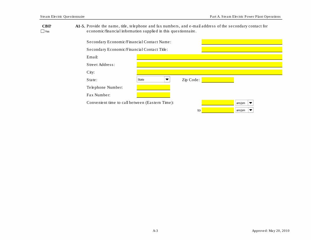
CBI? A1-5.
Secondary Economic/Financial Contact Name:
Secondary Economic/Financial Contact Title:
Email:
Street Address:
City:
State: Zip Code:
Telephone Number:
Fax Number:
Convenient time to call between (Eastern Time):
to
Provide the name, title, telephone and fax numbers, and e-mail address of the secondary contact for
economic/financial information supplied in this questionnaire. Yes
State
am/pm
am/pm
A-3 Approved: May 20, 2010

Steam Electric Questionnaire Part A. Steam Electric Power Plant Operations
Plant ID: Insert Plant ID
Plant Name: Insert Plant Name
Part: A
Section Title: 1.2. General Plant Operating Characteristics
Instructions:
CBI? A1-6.
STOPSTOP! IF YOU ANSWERED YES TO QUESTION A1-6,
DO NOT COMPLETE THE REMAINDER OF THIS QUESTIONNAIRE.
CBI? A1-7.
(Continue)
(Stop)
STOP! IF YOU ANSWERED NO TO QUESTION A1-7,
DO NOT COMPLETE THE REMAINDER OF THIS QUESTIONNAIRE.
Throughout Section 1.2 (Questions A1-6 to A1-14), provide information requested on general plant operating characteristics.
Please provide all free response answers in the highlighted yellow areas.
Does the plant generate or have the potential to generate electricity from a steam electric generating unit (i.e., a generating unit
that utilizes a thermal cycle employing the steam/water system as the thermodynamic medium (steam turbine))? [NOTE:
Combined cycle systems with at least one associated steam turbine are considered steam electric generating units.]
(Stop)
(Continue)
Is the plant permanently retired or will it be permanently retired by December 31, 2011?
Yes
Yes
No, this plant does not generate or have the potential to generate electricity from a steam electric generating unit.
Yes
No
Yes
A-4 Approved: May 20, 2010

Steam Electric Questionnaire Part A. Steam Electric Power Plant Operations
CBI? A1-8.
STOP! IF YOU ANSWERED NONE IN QUESTION A1-8,
DO NOT COMPLETE THE REMAINDER OF THIS QUESTIONNAIRE.
CBI? A1-9.
%
%
%
If “Other” was selected, use the yellow space below to provide a description of electricity end use/handling.
CBI? A1-10.
Primary NAICS:
Secondary NAICS:
Tertiary NAICS:
Indicate all of the fossil or nuclear fuels that the plant used to generate electricity in 2009 (refer to Table A-17 for a further
breakdown of fossil-type fuels in the "Type of Fuel" tab). [NOTE: Do NOT include fuels only used for start up or emergency
generators when answering this question.]
Provide the primary, secondary, and tertiary six-digit North American Industry Classification System (NAICS) codes that best
describe the plant’s activities. Refer to the U.S. Census Bureau’s website to identify appropriate NAICS codes
(http://www.census.gov/eos/www/naics/).
Identify how the plant uses/handles the electricity generated and indicate the percent of electricity by end use/handling. [Check
all boxes that apply.]
Coal
Oil
Gas
Petroleum Coke
Nuclear Fuel
None (the plant did not use fossil or nuclear fuels other than for start up in 2009)
Used on site
Distributed for sale
Other
Yes
Yes
Yes
A-5 Approved: May 20, 2010

Steam Electric Questionnaire Part A. Steam Electric Power Plant Operations
CBI? A1-11.
STOP! IF YOU ANSWERED NO IN QUESTION A1-11,
DO NOT COMPLETE THE REMAINDER OF THIS QUESTIONNAIRE.
CBI? A1-12.
%
%
%
If “Other” was selected, use the space below to provide a description of the use for steam.
CBI? A1-13.
Nameplate capacity MW
Net summer capacity MW
Net winter capacity MW
Is the generation of electricity the primary purpose (i.e., the predominant source of revenue and principal reason for operation)
of the plant?
Provide the total plant nameplate electric generating capacity, as reported in U.S. DOE/EIA Form 860, schedule 3, line 1, and
the total electric net summer and winter capacities.
Identify how the plant uses steam generated at the plant and indicate the percent of steam by use. [Check all boxes that apply.]
Electricity Generation
Heating and/or Cooling
Other
Yes
Yes
Yes
No, specify the primary purpose of the plant to the right:
Yes
A-6 Approved: May 20, 2010

Steam Electric Questionnaire Part A. Steam Electric Power Plant Operations
CBI? A1-14.
Calendar Year
2007 MW-hrs MW-hrs
2008 MW-hrs MW-hrs
2009 MW-hrs MW-hrs
Net Electrical Generation (MW-
hrs)
Gross Electrical
Generation (MW-hrs)
In Table A-1, provide the total net and gross electrical generation for all electric generating units at the plant during calendar
years 2007 through 2009.
Table A-1. Net and Gross Plant Electrical Generation for 2007-2009
Yes
A-7 Approved: May 20, 2010

Steam Electric Questionnaire Part A. Steam Electric Power Plant Operations
Plant ID: Insert Plant ID
Plant Name: Insert Plant Name
Part: A
Section Title: 2.1. Plant Identification and Information on Permits and Studies
Instructions:
CBI? A2-1.
EIA Plant Identification Code:
CBI? A2-2.
RUS Plant Identification Code:
CBI? A2-3.
(Continue)
(Skip to Question A2-4)
If yes, please attach results from the study(ies).
CBI? A2-4. In Table A-2, provide a list of the plant’s most recently approved permits that are associated with industrial activities. If the plant
has more than one ID for a permit type, list all IDs in the space provided. Also indicate if the plant has a new/pending permit under
development.
Provide the identification code of this plant as reported on U.S. DOE/EIA Form-860, "Annual Electric Generator Report," schedule
2, line 1.
Throughout Section 2.1 (Question A2-1 to A2-4), provide information requested on plant identity, permits, and studies. Please
provide all free response answers in the highlighted yellow areas.
Provide the identification code of this plant as used when reporting to the Rural Utilities Service (RUS).
Did the plant conduct any Environmental Assessment (EA) or Environmental Impact Statement (EIS) studies on receiving waters
or pond/impoundments reported in Table A-4?
Note: Do NOT include the following types of permits: permits required for construction of wastewater and/or sanitary sewage
facilities, erosion and sediment control permits associated with construction activities, temporary and general permits for
hydrostatic testing water, water obstruction and encroachment permits, and/or water allocation permits.
Yes
Check here if not applicable
Check here if not applicable
Yes
Yes
Yes
No
I have attached the results from the study(ies)
I did not attach the results from the study(ies). Explain why:
Yes
A-8 Approved: May 20, 2010

Steam Electric Questionnaire Part A. Steam Electric Power Plant Operations
Month Year Month Year
If the plant does not have an individual NPDES permit , skip to Section 3.
Underground Injection Control
(UIC)
Approval Date
Permit Type Permit ID(s)
National Pollutant Discharge
Elimination System (NPDES)
Resource Conservation and
Recovery Act (RCRA)
Stormwater
Air Pollution Operating
Table A-2. Permit Information
Expiration Date
New/Pending
Permit is Under
Development
Month Year Month
Month Year Month
Month Year Month
Month Year Month
Month Year Month
Month Year Month
Month Year Month
Month Year Month
Month Year Month
Month Year Month
Month Year Month
Month Year Month
Month Year Month
Month Year Month
Month Year Month
Year
Year
Year
Year
Year
Year
Year
Year
Year
Year
Year
Year
Year
Year
Year
Yes/No
Yes/No
Yes/No
Yes/No
Yes/No
A-9 Approved: May 20, 2010

Steam Electric Questionnaire Part A. Steam Electric Power Plant Operations
Plant ID: Insert Plant ID
Plant Name: Insert Plant Name
Outfall Number: Insert Outfall Number
Part: A
Section Title: 2.2. Outfall Information
Instructions:
CBI? A2-5.
Outfall Name:
Coordinates Degrees Minutes Seconds
Latitude
Longitude
Discharge Flow: gpy gpd gpm
and and and
dpy OR dpy OR hpd
and
dpy
CBI? A2-6. Identify if the outfall is an internal or final outfall.
(Continue)
Provide the name, latitude/longitude, the typical volume of discharge in 2009 (either gpd and gpy OR gpm and hpd if flow is
intermittent), and the number of days of discharge in 2009 for the outfall.
Throughout Section 2.2 (Questions A2-5 to A2-10), provide information for all internal and final outfalls designated in the plant's
NPDES permit. Note: This section does not require information on stormwater outfalls, other than those storm water outfalls
that may be identified in the NPDES permit itself. Please provide all free response answers in the highlighted yellow areas.
Make copies of Section 2.2 for each outfall designated in the plant's NPDES permit using the "Copy Section 2.2" button below.
Enter the outfall number in the space provided above.
(Skip to Section 3)
Yes
Yes
Internal Outfall
Final Outfall
Copy Section 2.2
A-10 Approved: May 20, 2010

Steam Electric Questionnaire Part A. Steam Electric Power Plant Operations
CBI? A2-7.
CBI? A2-8.
Receiving Surface Water Name:
Type of Surface Water: Other, specify:
CBI? A2-9. Has a mixing zone been applied to the outfall?
CBI? A2-10.
Coal Pile Runoff
Metal Cleaning Waste
Storm Water
100%
Does the outfall release water to a discharge canal prior to discharging to surface water?
Provide the receiving surface water name and type of surface water. If the receiving surface water is unnamed, provide the
name(s) of the next receiving water downstream with a designated name.
If the receiving surface water is unnamed, provide the name(s)
of the next receiving water downstream with a designated
name.
In Table A-3, provide the percent contribution that each wastewater listed has to the total outfall flow.
Table A-3. Wastewaters Discharged Through Outfall
Wastewater
Leachate from Coal Combustion Residue Landfills or Ponds/Impoundments
Percent Contribution of
Outfall Flow
Other
Total
Cooling Water
Bottom Ash Sluice
FGD Scrubber Wastewater (slurry blowdown or scrubber purge)
Fly Ash Sluice
Type of Receiving Water
Yes
Yes
Yes
Yes
Yes
No
Yes
No
Outfall is used for emergency discharges only. (Respondent still required to answer Table A-3.)
A-11 Approved: May 20, 2010
Steam Electric Questionnaire Part A. Steam Electric Power Plant Operations
Plant ID: Insert Plant ID
Plant Name: Insert Plant Name
Part: A
Section Title: 3. Ponds/Impoundments
Instructions:
CBI? A3-1.
(Continue)
(Skip to Section 4)
CBI? A3-2.
Closest Distance
to Nearest Surface
Water
deg min sec (ft)
Lat:
Long:
Lat:
Long:
Lat:
Long:
Lat:
Long:
Lat:
Long:
Lat:
Long:
Lat:
Long:
Table A-4. Identification of Plant Pond/Impoundment Units
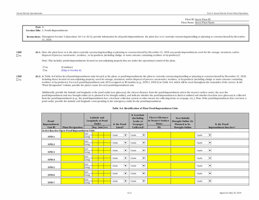
Throughout Section 3 (Questions A3-1 to A3-3), provide information for all ponds/impoundments the plant has or is currently constructing/installing or planning to construct/install by December
31, 2020.
Does the plant have or is the plant currently constructing/installing or planning to construct/install by December 31, 2020 any ponds/impoundments used for the storage, treatment, and/or
disposal of process wastewater , residues , or by-products (including sludge or water streams containing residues or by-products)?
In Table A-4 below list all pond/impoundment units located at the plant, or pond/impoundments the plant is currently constructing/installing or planning to construct/install by December 31, 2020,
including those located on non-adjoining property, used for storage, treatment, and/or disposal of process wastewater, residues, or by-products (including sludge or water streams containing
residues or by-products). For each pond/impoundment unit, EPA assigned an ID number (e.g., SPD-1, SPD-2) in Table A-4, which will be used throughout the remainder of the survey. In the
“Plant Designation” column, provide the plant’s name for each pond/impoundment unit.
Additionally, provide the latitude and longitude at the pond outlet (see glossary), the closest distance from the pond/impoundment unit to the nearest surface water, the year the
pond/impoundment unit was brought online (or is planned to be brought online), and indicate whether the pond/impoundment is lined or unlined and whether leachate (see glossary) is collected
from the pond/impoundment (e.g., the pond/impoundment has a leachate collection system or other means for collecting leaks or seepage, etc.). Note: If the pond/impoundment does not have a
pond outlet, provide the latitude and longitude corresponding to the emergency outlet for the pond/impoundment.
Note: This includes ponds/impoundments located on non-adjoining property that are under the operational control of the plant.
Is the Pond/
Impoundment Inactive?
Latitude and
Longitude at Pond
Outlet
SPD-7
SPD-6
SPD-5
SPD-4
SPD-3
SPD-2
Year Initially
Brought Online Or
Planned to be
Brought Online
Active/Inactive/Open Pond/Impoundment Units
SPD-1
Pond/
Impoundment
Unit ID Plant Designation
Is the Pond
Lined?
Is Leachate
(including
Leaks or
Seepage)
Collected?
Yes/No Yes/No
Yes/No Yes/No
Yes/No Yes/No
Yes/No Yes/No
Yes/No Yes/No
Yes/No Yes/No
Yes/No Yes/No
Yes
No
Yes
Yes
Yes/No
Yes/No
Yes/No
Yes/No
Yes/No
Yes/No
Yes/No
A-12 Approved: May 20, 2010

Steam Electric Questionnaire Part A. Steam Electric Power Plant Operations
Lat:
Long:
Lat:
Long:
Lat:
Long:
Lat:
Long:
Lat:
Long:
Lat:
Long:
Lat:
Long:
Retired/Closed Pond/Impoundment Units
Lat:
Long:
Lat:
Long:
Lat:
Long:
Lat:
Long:
Planned Pond/Impoundment Units
Lat:
Long:
Lat:
Long:
Lat:
Long:
Lat:
Long:
Lat:
Long:
SPD-C
SPD-B
SPD-A
RET-SPD-4
RET-SPD-3
RET-SPD-2
RET-SPD-1
SPD-10
SPD-9
SPD-8
SPD-D
SPD-11
SPD-E
SPD-12
SPD-13
SPD-14
Yes/No Yes/No
Yes/No Yes/No
Yes/No Yes/No
Yes/No Yes/No
Yes/No Yes/No
Yes/No Yes/No
Yes/No Yes/No
Yes/No Yes/No
Yes/No Yes/No
Yes/No Yes/No
Yes/No Yes/No
Yes/No Yes/No
Yes/No
Yes/No
Yes/No
Yes/No Yes/No Yes/No
Yes/No Yes/No Yes/No
Yes/No Yes/No Yes/No
Yes/No Yes/No Yes/No
A-13 Approved: May 20, 2010

Steam Electric Questionnaire Part A. Steam Electric Power Plant Operations
CBI? A3-3.
Pond/
Impoundment
Unit ID
Other, specify: Other, specify:
Other, specify: Other, specify:
Other, specify: Other, specify:
Other, specify: Other, specify:
Other, specify: Other, specify:
Other, specify: Other, specify:
Other, specify: Other, specify:
Other, specify: Other, specify:
Other, specify: Other, specify:
Other, specify: Other, specify:
Other, specify: Other, specify:
Other, specify: Other, specify:
Other, specify: Other, specify:
Other, specify: Other, specify:
Other, specify: Other, specify:
Other, specify: Other, specify:
Table A-5. Wastes Stored or Disposed of in Plant Pond/Impoundment Units
In Table A-5 below, indicate all process wastewater, residues, or by-products (or sludges or water streams containing the wastes, residues or by-products) that are stored, treated, and/ or
disposed of in each pond/impoundment unit identified in Table A-4. [Check all boxes that apply.] For solid waste and process wastewater not listed in the checkboxes or the drop down menu
provide the name and description in the yellow box provided. Do not include treatment chemicals that are added to the pond/impoundment.
Process WastewaterSolid Waste
Pond/Impoundment Unit ID
Pond/Impoundment Unit ID
Pond/Impoundment Unit ID
Pond/Impoundment Unit ID
Yes
Boiler Slag
Bottom Ash
FGD Calcium Sulfate (Gypsum)
Fly Ash
Solids from Dry FGD
FGD Calcium Sulfite – Not Pozzolanic
FGD Pozzolanic Material
Boiler Slag
Bottom Ash
FGD Calcium Sulfate (Gypsum)
Fly Ash
Solids from Dry FGD
FGD Calcium Sulfite – Not Pozzolanic
FGD Pozzolanic Material
Boiler Slag
Bottom Ash
FGD Calcium Sulfate (Gypsum)
Fly Ash
Solids from Dry FGD
FGD Calcium Sulfite – Not Pozzolanic
FGD Pozzolanic Material
Boiler Slag
Bottom Ash
FGD Calcium Sulfate (Gypsum)
Fly Ash
Solids from Dry FGD
FGD Calcium Sulfite – Not Pozzolanic
FGD Pozzolanic Material
Process Wastewaters
Process Wastewaters Process Wastewaters
Process Wastewaters Process Wastewaters
Process Wastewaters
Process Wastewaters
Process Wastewaters Process Wastewaters
Process Wastewaters Process Wastewaters
Process Wastewaters
Process Wastewaters
Process Wastewaters Process Wastewaters
Process Wastewaters Process Wastewaters
Process Wastewaters
Process Wastewaters
Process Wastewaters Process Wastewaters
Process Wastewaters Process Wastewaters
Process Wastewaters
A-14 Approved: May 20, 2010
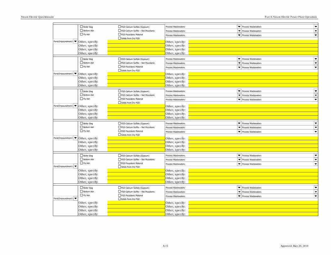
Steam Electric Questionnaire Part A. Steam Electric Power Plant Operations
Other, specify: Other, specify:
Other, specify: Other, specify:
Other, specify: Other, specify:
Other, specify: Other, specify:
Other, specify: Other, specify:
Other, specify: Other, specify:
Other, specify: Other, specify:
Other, specify: Other, specify:
Other, specify: Other, specify:
Other, specify: Other, specify:
Other, specify: Other, specify:
Other, specify: Other, specify:
Other, specify: Other, specify:
Other, specify: Other, specify:
Other, specify: Other, specify:
Other, specify: Other, specify:
Other, specify: Other, specify:
Other, specify: Other, specify:
Other, specify: Other, specify:
Other, specify: Other, specify:
Other, specify: Other, specify:
Other, specify: Other, specify:
Other, specify: Other, specify:
Other, specify: Other, specify:
Pond/Impoundment Unit ID
Pond/Impoundment Unit ID
Pond/Impoundment Unit ID
Pond/Impoundment Unit ID
Pond/Impoundment Unit ID
Pond/Impoundment Unit ID
Boiler Slag
Bottom Ash
FGD Calcium Sulfate (Gypsum)
Fly Ash
Solids from Dry FGD
FGD Calcium Sulfite – Not Pozzolanic
FGD Pozzolanic Material
Boiler Slag
Bottom Ash
FGD Calcium Sulfate (Gypsum)
Fly Ash
Solids from Dry FGD
FGD Calcium Sulfite – Not Pozzolanic
FGD Pozzolanic Material
Boiler Slag
Bottom Ash
FGD Calcium Sulfate (Gypsum)
Fly Ash
Solids from Dry FGD
FGD Calcium Sulfite – Not Pozzolanic
FGD Pozzolanic Material
Boiler Slag
Bottom Ash
FGD Calcium Sulfate (Gypsum)
Fly Ash
Solids from Dry FGD
FGD Calcium Sulfite – Not Pozzolanic
FGD Pozzolanic Material
Boiler Slag
Bottom Ash
FGD Calcium Sulfate (Gypsum)
Fly Ash
Solids from Dry FGD
FGD Calcium Sulfite – Not Pozzolanic
FGD Pozzolanic Material
Boiler Slag
Bottom Ash
FGD Calcium Sulfate (Gypsum)
Fly Ash
Solids from Dry FGD
FGD Calcium Sulfite – Not Pozzolanic
FGD Pozzolanic Material
Process Wastewaters
Process Wastewaters Process Wastewaters
Process Wastewaters Process Wastewaters
Process Wastewaters
Process Wastewaters
Process Wastewaters Process Wastewaters
Process Wastewaters Process Wastewaters
Process Wastewaters
Process Wastewaters
Process Wastewaters Process Wastewaters
Process Wastewaters Process Wastewaters
Process Wastewaters
Process Wastewaters
Process Wastewaters Process Wastewaters
Process Wastewaters Process Wastewaters
Process Wastewaters
Process Wastewaters
Process Wastewaters Process Wastewaters
Process Wastewaters Process Wastewaters
Process Wastewaters
Process Wastewaters
Process Wastewaters Process Wastewaters
Process Wastewaters Process Wastewaters
Process Wastewaters
A-15 Approved: May 20, 2010
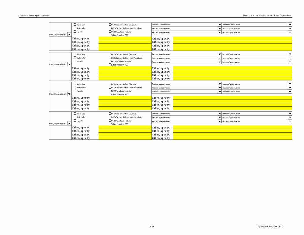
Steam Electric Questionnaire Part A. Steam Electric Power Plant Operations
Other, specify: Other, specify:
Other, specify: Other, specify:
Other, specify: Other, specify:
Other, specify: Other, specify:
Other, specify: Other, specify:
Other, specify: Other, specify:
Other, specify: Other, specify:
Other, specify: Other, specify:
Other, specify: Other, specify:
Other, specify: Other, specify:
Other, specify: Other, specify:
Other, specify: Other, specify:
Other, specify: Other, specify:
Other, specify: Other, specify:
Other, specify: Other, specify:
Other, specify: Other, specify:
Pond/Impoundment Unit ID
Pond/Impoundment Unit ID
Pond/Impoundment Unit ID
Pond/Impoundment Unit ID
Boiler Slag
Bottom Ash
FGD Calcium Sulfate (Gypsum)
Fly Ash
Solids from Dry FGD
FGD Calcium Sulfite – Not Pozzolanic
FGD Pozzolanic Material
Boiler Slag
Bottom Ash
FGD Calcium Sulfate (Gypsum)
Fly Ash
Solids from Dry FGD
FGD Calcium Sulfite – Not Pozzolanic
FGD Pozzolanic Material
Boiler Slag
Bottom Ash
FGD Calcium Sulfate (Gypsum)
Fly Ash
Solids from Dry FGD
FGD Calcium Sulfite – Not Pozzolanic
FGD Pozzolanic Material
Boiler Slag
Bottom Ash
FGD Calcium Sulfate (Gypsum)
Fly Ash
Solids from Dry FGD
FGD Calcium Sulfite – Not Pozzolanic
FGD Pozzolanic Material
Process Wastewaters
Process Wastewaters Process Wastewaters
Process Wastewaters Process Wastewaters
Process Wastewaters
Process Wastewaters
Process Wastewaters Process Wastewaters
Process Wastewaters Process Wastewaters
Process Wastewaters
Process Wastewaters
Process Wastewaters Process Wastewaters
Process Wastewaters Process Wastewaters
Process Wastewaters
Process Wastewaters
Process Wastewaters Process Wastewaters
Process Wastewaters Process Wastewaters
Process Wastewaters
A-16 Approved: May 20, 2010

Steam Electric Questionnaire Part A. Steam Electric Power Plant Operations
Plant ID: Insert Plant ID
Plant Name: Insert Plant Name
Part: A
Section Title: 4. Landfills
Instructions:
CBI? A4-1.
(Continue)
(Skip to Section 5)
CBI? A4-2.
deg min sec
Lat:
Long:
Lat:
Long:
Lat:
Long:
Lat:
Long:
Throughout Section 4 (Questions A4-1 to A4-3), provide information for landfills (see glossary) the plant has or is currently constructing/installing or planning to
construct/install by December 31, 2020.
Note: This includes landfills located on non-adjoining property that are under the operational control of the plant. This also includes landfills, within 20 miles,
owned/operated by the plant's ultimate parent firm, for the purpose of storing/disposing of process wastewaters, residues, or by-products from the plant.
Does the plant have or is the plant currently constructing/installing or planning to construct/install by December 31, 2020 any landfills used for the storage or
disposal of process wastewater , residues , or by-products?
Is the Landfill
Inactive?Landfill ID
Plant
Designation
Latitude and
Longitude at Center of
Landfill Is the Landfill
Lined?
Is Leachate
Collected?
Year Initially
Brought Online Or
Planned to be
Brought Online
Closest Distance to
Nearest Surface
Water (ft)
Active/Inactive/Open Landfills
LANDFILL-1
LANDFILL-3
LANDFILL-2
LANDFILL-4
Table A-6. Identification of Plant Landfills
In Table A-6 below, list all landfills located at the plant, or landfills the plant (or ultimate parent firm) is currently constructing/installing or planning to
construct/install by December 31, 2020, including those located on non-adjoining property, used for storage or disposal of process wastewater, residues, or by-
products from the plant. For each landfill, EPA assigned an ID number (e.g., LANDFILL-1, LANDFILL-2) in Table A-6, which will be used throughout the remainder
of the survey. In the “Plant Designation” column, provide the plant’s name for each landfill. Additionally, provide the latitude and longitude at the center of the
landfill, the closest distance from the landfill to the nearest surface water, the year the landfill was brought online (or is planned to be brought online), and indicate
whether the landfill is lined or unlined and whether leachate is collected from the landfill (i.e., the landfill has a leachate collection system or other collection
system).
Yes/No Yes/No
Yes/No Yes/No
Yes/No Yes/No
Yes/No Yes/No
Yes
Yes
No
Yes
Yes/No
Yes/No
Yes/No
Yes/No
A-17 Approved: May 20, 2010

Steam Electric Questionnaire Part A. Steam Electric Power Plant Operations
Retired/Closed Landfills
Lat:
Long:
Lat:
Long:
Lat:
Long:
Lat:
Long:
Planned Landfills
Lat:
Long:
Lat:
Long:
Lat:
Long:
Lat:
Long:
RET-
LANDFILL-1
RET-
LANDFILL-3
RET-
LANDFILL-2
LANDFILL-A
RET-
LANDFILL-4
LANDFILL-C
LANDFILL-B
LANDFILL-D
Yes/No Yes/No
Yes/No Yes/No
Yes/No Yes/No
Yes/No Yes/No
Yes/No Yes/No
Yes/No Yes/No
Yes/No Yes/No
Yes/No Yes/No
A-18 Approved: May 20, 2010

Steam Electric Questionnaire Part A. Steam Electric Power Plant Operations
CBI? A4-3.
Landfill ID
Other, specify:
Other, specify:
Other, specify:
Other, specify:
Other, specify:
Other, specify:
Other, specify:
Other, specify:
Other, specify:
Other, specify:
Other, specify:
Other, specify:
Other, specify:
Other, specify:
Other, specify:
Other, specify:
In Table A-7 below, indicate all process wastewater , residues or by-products that are stored or disposed of in each landfill identified in Table A-6. [Check all
boxes that apply.] For solid waste not listed in the checkboxes provide the name and description in the yellow box provided.
Waste Stored or Disposed of in Landfill
Table A-7. Wastes Stored or Disposed of in Landfills
Landfill ID
Landfill ID
Landfill ID
Landfill ID
Yes
Boiler Slag
Bottom Ash
FGD Calcium Sulfate (Gypsum)
Fly Ash
Solids from Dry FGD
FGD Calcium Sulfite – Not Pozzolanic
FGD Pozzolanic Material
Boiler Slag
Bottom Ash
FGD Calcium Sulfate (Gypsum)
Fly Ash
Solids from Dry FGD
FGD Calcium Sulfite – Not Pozzolanic
FGD Pozzolanic Material
Boiler Slag
Bottom Ash
FGD Calcium Sulfate (Gypsum)
Fly Ash
Solids from Dry FGD
FGD Calcium Sulfite – Not Pozzolanic
FGD Pozzolanic Material
Boiler Slag
Bottom Ash
FGD Calcium Sulfate (Gypsum)
Fly Ash
Solids from Dry FGD
FGD Calcium Sulfite – Not Pozzolanic
FGD Pozzolanic Material
A-19 Approved: May 20, 2010

Steam Electric Questionnaire Part A. Steam Electric Power Plant Operations
Other, specify:
Other, specify:
Other, specify:
Other, specify:
Other, specify:
Other, specify:
Other, specify:
Other, specify:
Other, specify:
Other, specify:
Other, specify:
Other, specify:
Other, specify:
Other, specify:
Other, specify:
Other, specify:
Landfill ID
Landfill ID
Landfill ID
Landfill ID
Boiler Slag
Bottom Ash
FGD Calcium Sulfate (Gypsum)
Fly Ash
Solids from Dry FGD
FGD Calcium Sulfite – Not Pozzolanic
FGD Pozzolanic Material
Boiler Slag
Bottom Ash
FGD Calcium Sulfate (Gypsum)
Fly Ash
Solids from Dry FGD
FGD Calcium Sulfite – Not Pozzolanic
FGD Pozzolanic Material
Boiler Slag
Bottom Ash
FGD Calcium Sulfate (Gypsum)
Fly Ash
Solids from Dry FGD
FGD Calcium Sulfite – Not Pozzolanic
FGD Pozzolanic Material
Boiler Slag
Bottom Ash
FGD Calcium Sulfate (Gypsum)
Fly Ash
Solids from Dry FGD
FGD Calcium Sulfite – Not Pozzolanic
FGD Pozzolanic Material
A-20 Approved: May 20, 2010

Steam Electric Questionnaire Part A. Steam Electric Power Plant Operations
Other, specify:
Other, specify:
Other, specify:
Other, specify:
Other, specify:
Other, specify:
Other, specify:
Other, specify:
Landfill ID
Landfill ID
Boiler Slag
Bottom Ash
FGD Calcium Sulfate (Gypsum)
Fly Ash
Solids from Dry FGD
FGD Calcium Sulfite – Not Pozzolanic
FGD Pozzolanic Material
Boiler Slag
Bottom Ash
FGD Calcium Sulfate (Gypsum)
Fly Ash
Solids from Dry FGD
FGD Calcium Sulfite – Not Pozzolanic
FGD Pozzolanic Material
A-21 Approved: May 20, 2010
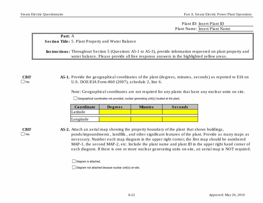
Steam Electric Questionnaire Part A. Steam Electric Power Plant Operations
Plant ID: Insert Plant ID
Plant Name: Insert Plant Name
Part: A
Section Title:
Instructions:
CBI? A5-1.
Degrees Minutes Seconds
CBI? A5-2.
5. Plant Property and Water Balance
Attach an aerial map showing the property boundary of the plant that shows buildings,
ponds/impoundments , landfills , and other significant features of the plant. Provide as many maps as
necessary. Number each map diagram in the upper right corner; the first map should be numbered
MAP-1, the second MAP-2, etc. Include the plant name and plant ID in the upper right hand corner of
each diagram. If there is one or more nuclear generating units on-site, an aerial map is NOT required.
Coordinate
Latitude
Longitude
Provide the geographical coordinates of the plant (degrees, minutes, seconds) as reported to EIA on
U.S. DOE/EIA Form-860 (2007), schedule 2, line 6.
Note: Geographical coordinates are not required for any plants that have any nuclear units on site.
Throughout Section 5 (Questions A5-1 to A5-3), provide information requested on plant property and
water balance. Please provide all free response answers in the highlighted yellow areas.
Yes
Yes
Diagram is attached.
Geographical coordinates not provided, nuclear generating unit(s) located at the plant.
Diagram not attached because nuclear unit(s) on-site.
A-22 Approved: May 20, 2010

Steam Electric Questionnaire Part A. Steam Electric Power Plant Operations
CBI? A5-3.
Block Diagram Checklist
Mark the boxes below to verify that you have completed each checklist item...
Provide as many diagrams as necessary to convey the information requested in the checklist below.
Number each block diagram in the upper right corner; the first block diagram should be numbered
WB-1, the second WB-2, etc. Include the plant name and plant ID in the upper right hand corner of
the diagram.
Include the water balance diagram number, plant name, and plant ID on the diagram.
Show and label all water sources (e.g., lakes and rivers), process wastewater generated by each
steam electric generating unit and process operation, and outfalls. Use the codes provided in the
Codes Tables tab. Effluent streams may include process wastewater and sludges .
Attach a water balance diagram for the plant that shows all sources of water, plant process
operations , process wastewaters generated and how they are handled/treated , flow rates of all water
streams, and all outfalls at the plant. Specific instructions for the diagram are provided in the checklist
below.
NOTE: You may use an existing diagram, such as a water balance diagram included in the
plant’s NPDES Form 2C, and mark the additional required information on the diagram by hand.
You may also use a diagram from previous years as long as the diagram is still representative
of current operations.
Diagram is attached.
Yes
A-23 Approved: May 20, 2010

Steam Electric Questionnaire Part A. Steam Electric Power Plant Operations
Review:
Identify the final destination of the treated wastewater and process wastewater (e.g., treated
wastewater effluent to POTW or surface waters; solid wastes to on- or off-site destinations). Use
codes provided in the Codes Table tab.
Indicate, as appropriate, where treated wastewater is reused or recycled within the plant (e.g.,
reuse of settling pond/impoundment water as fly ash sluice).
Identify all outfall locations. Include NPDES permit outfall numbers, if applicable.
Provide the typical flow rates for all streams on the diagram (in gpm or gpd). If the wastewater
stream is intermittent, provide amount and frequency; for example “100 gal, twice/day, 100 dpy”
or “1000 gpm, 4 hpd, 365 dpy”. For sludges, provide amount in tpd.
Identify all wastewater treatment systems used to treat the process wastewaters generated by
the steam electric generating units. Represent the wastewater treatment systems as a block or
other shape. Use EPA-assigned numbers from other parts of the questionnaire if applicable. If
the wastewater treatment system does not have an EPA-assigned number, use the plant-
designated name for the wastewater treatment system.
If you believe that the diagram should be treated as confidential, stamp it "Confidential" or write
"Confidential" or "CBI" across the top. If any diagram is not marked "Confidential", it will be
considered nonconfidential under 40 CFR Part 2, Subpart B.
If any of the statements above were not checked, revise the block diagram(s) and ensure all
statements have been checked.
A-24 Approved: May 20, 2010

Steam Electric Questionnaire Part A. Steam Electric Power Plant Operations
Figure A-1: Example Water Balance Diagram
A-25 Approved: May 20, 2010
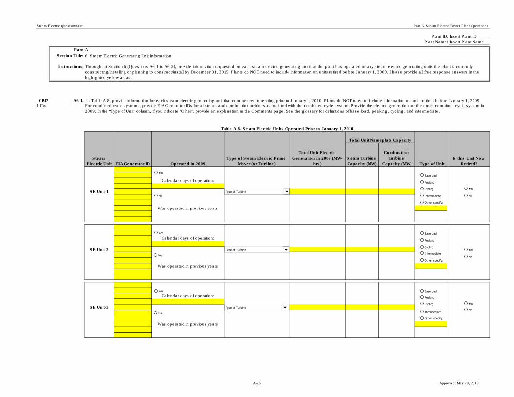
Steam Electric Questionnaire Part A. Steam Electric Power Plant Operations
Plant ID: Insert Plant ID
Plant Name: Insert Plant Name
Part: A
Section Title: 6. Steam Electric Generating Unit Information
Instructions:
CBI? A6-1.
Steam Turbine
Capacity (MW)
Combustion
Turbine
Capacity (MW)
Calendar days of operation:
SE Unit-1
Calendar days of operation:
SE Unit-2
Calendar days of operation:
SE Unit-3
Table A-8. Steam Electric Units Operated Prior to January 1, 2010
Throughout Section 6 (Questions A6-1 to A6-2), provide information requested on each steam electric generating unit that the plant has operated or any steam electric generating units the plant is currently
constructing/installing or planning to construct/install by December 31, 2015. Plants do NOT need to include information on units retired before January 1, 2009. Please provide all free response answers in the
highlighted yellow areas.
In Table A-8, provide information for each steam electric generating unit that commenced operating prior to January 1, 2010. Plants do NOT need to include information on units retired before January 1, 2009.
For combined cycle systems, provide EIA Generator IDs for all steam and combustion turbines associated with the combined cycle system. Provide the electric generation for the entire combined cycle system in
2009. In the “Type of Unit” column, if you indicate “Other”, provide an explanation in the Comments page. See the glossary for definitions of base load, peaking , cycling , and intermediate .
Type of Unit
Is this Unit Now
Retired?
Total Unit Nameplate Capacity
Steam
Electric Unit EIA Generator ID Operated in 2009
Type of Steam Electric Prime
Mover (or Turbine)
Total Unit Electric
Generation in 2009 (MW-
hrs)
Was operated in previous years
Was operated in previous years
Was operated in previous years
Yes
Yes
No
Type of Turbine
Type of Turbine
Type of Turbine
Yes
No
Yes
No
Yes
No
Yes
No
Yes
No
Base load
Peaking
Cycling
Other, specify:
Base load
Peaking
Cycling
Intermediate
Other, specify:
Base load
Peaking
Cycling
Intermediate
Other, specify:
Intermediate
A-26 Approved: May 20, 2010

Steam Electric Questionnaire Part A. Steam Electric Power Plant Operations
Calendar days of operation:
SE Unit-4
Calendar days of operation:
SE Unit-5
Calendar days of operation:
SE Unit-6
Calendar days of operation:
SE Unit-7
Calendar days of operation:
SE Unit-8
Was operated in previous years
Was operated in previous years
Was operated in previous years
Was operated in previous years
Was operated in previous years
Type of Turbine
Type of Turbine
Type of Turbine
Type of Turbine
Type of Turbine
Yes
No
Yes
No
Yes
No
Yes
No
Yes
No
Yes
No
Yes
No
Yes
No
Yes
No
Yes
No
Base load
Peaking
Cycling
Intermediate
Other, specify:
Base load
Peaking
Cycling
Intermediate
Other, specify:
Base load
Peaking
Cycling
Intermediate
Other, specify:
Base load
Peaking
Cycling
Intermediate
Other, specify:
Base load
Peaking
Cycling
Intermediate
Other, specify:
A-27 Approved: May 20, 2010

Steam Electric Questionnaire Part A. Steam Electric Power Plant Operations
Calendar days of operation:
SE Unit-9
Calendar days of operation:
SE Unit-10
Was operated in previous years
Was operated in previous years
Type of Turbine
Type of Turbine
Yes
No
Yes
No
Yes
No
Yes
No
Base load
Peaking
Cycling
Intermediate
Other, specify:
Base load
Peaking
Cycling
Intermediate
Other, specify:
A-28 Approved: May 20, 2010

Steam Electric Questionnaire Part A. Steam Electric Power Plant Operations
CBI? A6-2.
Month Year
Steam Turbine
Capacity (MW)
Combustion
Turbine
Capacity (MW)
SE Unit-A
SE Unit-B
SE Unit-C
SE Unit-D
Steam
Electric Unit
Total Unit Nameplate Capacity
In Table A-9, provide information for each steam electric generating unit that commenced operating after December 31, 2009, or the plant is currently constructing/installing
or planning to construct/install by December 31, 2015. For combined cycle systems, provide EIA Generator IDs for all steam and combustion turbines associated with the
combined cycle system and provide the total capacity for all steam turbines and combustion turbines separately (i.e., sum the respective capacity for all steam turbines and
combustion turbines associated with the combined cycle system). In the "Type of Boiler or Reactor" column, check all that apply. In the “Type of Unit” column, if you indicate
“Other”, provide an explanation in the Comments page. See the glossary for definitions of base load, peaking, cycling, and intermediate.
Initial Date of
Operation or Planned
Date of Operation
Type of Steam
Electric Prime
Mover (or Turbine)
Type of Boiler or Reactor
[check all that apply]
EIA Generator ID
(if applicable) or
Plant
Designation
Table A-9. Steam Electric Generating Units That Commenced Operating After December 31, 2009 or Planned Steam Electric Generating Units
Type of Unit
Yes
Month New Unit Year
Tangential-fired boiler
Wall-fired boiler
Cyclone-fired boiler
Waste heat recovery boiler (HRSG)
Other, specify below:
Type of Turbine
Month New Unit YearType of Turbine
Month New Unit YearType of Turbine
Month New Unit YearType of Turbine
Pressurized water reactor
Boiling water reactor
Pressurized heavy water reactor
Base load
Peaking
Cycling
Intermediate
Other, specify:
Base load
Peaking
Cycling
Intermediate
Other, specify:
Base load
Peaking
Cycling
Intermediate
Other, specify:
Base load
Peaking
Cycling
Intermediate
Other, specify:
Tangential-fired boiler
Wall-fired boiler
Cyclone-fired boiler
Waste heat recovery boiler (HRSG)
Other, specify below:
Pressurized water reactor
Boiling water reactor
Pressurized heavy water reactor
Tangential-fired boiler
Wall-fired boiler
Cyclone-fired boiler
Waste heat recovery boiler (HRSG)
Other, specify below:
Pressurized water reactor
Boiling water reactor
Pressurized heavy water reactor
Tangential-fired boiler
Wall-fired boiler
Cyclone-fired boiler
Waste heat recovery boiler (HRSG)
Other, specify below:
Pressurized water reactor
Boiling water reactor
Pressurized heavy water reactor
A-29 Approved: May 20, 2010

Steam Electric Questionnaire Part A. Steam Electric Power Plant Operations
Plant ID:
Plant Name:
Part: A
Section Title: 7. Condenser Cooling Water Systems
Instructions:
CBI? A7-1.
Trade Name Manufacturer Active Ingredient(s)
hpd
CS-1gpm dpy
Other:
hpd
CS-2gpm dpy
Other:
hpd
CS-3gpm dpy
Other:
Insert Plant ID
Insert Plant Name
Typical Duration AND
Frequency of
Generation/
Blowdown (hpd AND
dpy)
In Table A-10, provide information for all condenser cooling water systems currently operating at the plant and any condenser cooling water systems the plant is currently constructing/installing
or planning to construct/install by December 31, 2015. Indicate the type of condenser cooling system and the specific steam electric generating units that the system cools. [Check all boxes that
apply.] If the plant adds chemicals to the condenser cooling system, provide the chemical trade name, manufacturer, and active ingredient(s). If there is more than one active ingredient in the
chemical additive, include all of them in the yellow box provided. Separate multiple entries with commas. Enter the typical amount of process wastewater generated or blown down from the
cooling water system and the typical duration and frequency of generation or blow down. For planned cooling systems, provide this information to the extent known.
Throughout Section 7 (Questions A7-1 to A7-3), provide information requested for all condenser cooling water systems currently operating at the plant and any condenser cooling water systems
the plant is currently constructing/installing or planning to construct/install by December 31, 2015. Please provide all free response answers in the highlighted yellow areas.
Table A-10. Condenser Cooling Systems for All Steam Electric Generating Units
Cooling
System ID
Typical Amount of
Process
Wastewater
Generated/Blow
Down from Cooling
System (gpm)
Operating Condenser Cooling Water Systems
Chemical Additives Added to the Cooling System and
Make-up Water System
Type of Condenser
Cooling System
Steam Electric Units
that the System Cools
(check all boxes that
apply)
Yes
SE Unit 1
SE Unit 2
SE Unit 3
SE Unit 4
SE Unit 5
SE Unit 6
SE Unit 7
SE Unit 8
SE Unit 10
SE Unit B
SE Unit D
SE Unit 9
SE Unit A
SE Unit C
Type of Cooling System
Type of Cooling System
Type of Cooling System
SE Unit 1
SE Unit 2
SE Unit 3
SE Unit 4
SE Unit 5
SE Unit 6
SE Unit 7
SE Unit 8
SE Unit 10
SE Unit B
SE Unit D
SE Unit 9
SE Unit A
SE Unit C
SE Unit 1
SE Unit 2
SE Unit 3
SE Unit 4
SE Unit 5
SE Unit 6
SE Unit 7
SE Unit 8
SE Unit 10
SE Unit B
SE Unit D
SE Unit 9
SE Unit A
SE Unit C
A-30 Approved: May 20, 2010

Steam Electric Questionnaire Part A. Steam Electric Power Plant Operations
hpd
CS-Agpm dpy
Other:
hpd
CS-Bgpm dpy
Other:
hpd
CS-Cgpm dpy
Other:
CBI? A7-2.
CBI? A7-3. Is POTW effluent used in the cooling water system?
How did the plant demonstrate compliance with limits on priority pollutants for cooling tower blowdown from these cooling systems? [Check all boxes that apply.]
Planned Cooling Water Systems
Type of Cooling System
Type of Cooling System
Type of Cooling System
Waste stream monitoring
Plant does not operate cooling towers
Certification from supplier
Engineering calculations
Other, specify:
Plant does not have priority pollutant limits on cooling tower blowdown
Yes
SE Unit 1
SE Unit 2
SE Unit 3
SE Unit 4
SE Unit 5
SE Unit 6
SE Unit 7
SE Unit 8
SE Unit 10
SE Unit B
SE Unit D
SE Unit 9
SE Unit A
SE Unit C
SE Unit 1
SE Unit 2
SE Unit 3
SE Unit 4
SE Unit 5
SE Unit 6
SE Unit 7
SE Unit 8
SE Unit 10
SE Unit B
SE Unit D
SE Unit 9
SE Unit A
SE Unit C
SE Unit 1
SE Unit 2
SE Unit 3
SE Unit 4
SE Unit 5
SE Unit 6
SE Unit 7
SE Unit 8
SE Unit 10
SE Unit B
SE Unit D
SE Unit 9
SE Unit A
SE Unit C
YesYes
No
A-31 Approved: May 20, 2010
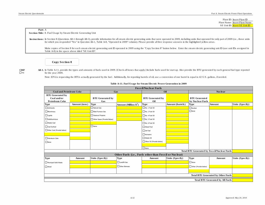
Steam Electric Questionnaire Part A. Steam Electric Power Plant Operations
Plant ID: Insert Plant ID
Plant Name: Insert Plant Name
SE Unit ID: Insert SE Unit ID
Part: A
Section Title:
Instructions:
CBI? A8-1.
Type Amount (tons) Type Amount (Million ft3) Type Amount (barrels) Type Amount Units (Specify)
Type Amount Units (Specify) Type Amount Units (Specify) Type Amount Units (Specify)
Fossil/Nuclear Fuels
Table A-11. Fuel Usage for Steam Electric Power Generation in 2009
In Section 8 (Questions A8-1 through A8-3), provide information for all steam electric generating units that were operated in 2009, including units that operated for only part of 2009 (i.e., those units
for which you responded "Yes" in Question A6-1, Table A-8, "Operated in 2009" column). Please provide all free response answers in the highlighted yellow areas.
8. Fuel Usage by Steam Electric Generating Unit
Make copies of Section 8 for each steam electric generating unit ID operated in 2009 using the "Copy Section 8" button below. Enter the steam electric generating unit ID (use unit IDs assigned in
Table A-8) in the space above titled "SE Unit ID".
In Table A-11, provide the types and amounts of fuels used in 2009. [Check all boxes that apply.] Include fuels used for start up. Also provide the BTU generated by each general fuel type reported
for the year 2009.
Note: EPA is requesting the BTUs actually generated by the fuel. Additionally, for reporting barrels of oil, use a conversion of one barrel is equal to 42 U.S. gallons, if needed.
Coal and Petroleum Coke NuclearOilGas
BTU Generated by
Coal and/or
Petroleum Coke
Total BTU Generated by Fossil/Nuclear Fuels
Other Fuels (i.e., Fuels other than Fossil or Nuclear)
Total BTU Generated by Other Fuels
Total BTU Generated by All Fuels
BTU Generated by
Gas
BTU Generated by
Oil
BTU Generated
by Nuclear Fuels
Yes
Copy Section 8
Bituminous
Subbituminous
Lignite
Other Coal (Provide below)
Petroleum Coke
None
Natural Gas
Blast Furnace Gas
Gaseous Propane
Other Gases (Provide Below)
None
No. 1 Fuel Oil
No. 2 Fuel Oil
No. 4 Fuel Oil
Other Oil (Provide below)
None
No. 5 Fuel Oil
No. 6 Fuel Oil
Nuclear
None
Anthracite
Coal Synfuel
Waste Coal
Kerosene
Jet Fuel
Diesel Fuel
Waste Oil
Municipal Solid Waste
Wood Other Biomass
NoneLandfill Gas
Other (Provide below)
A-32 Approved: May 20, 2010
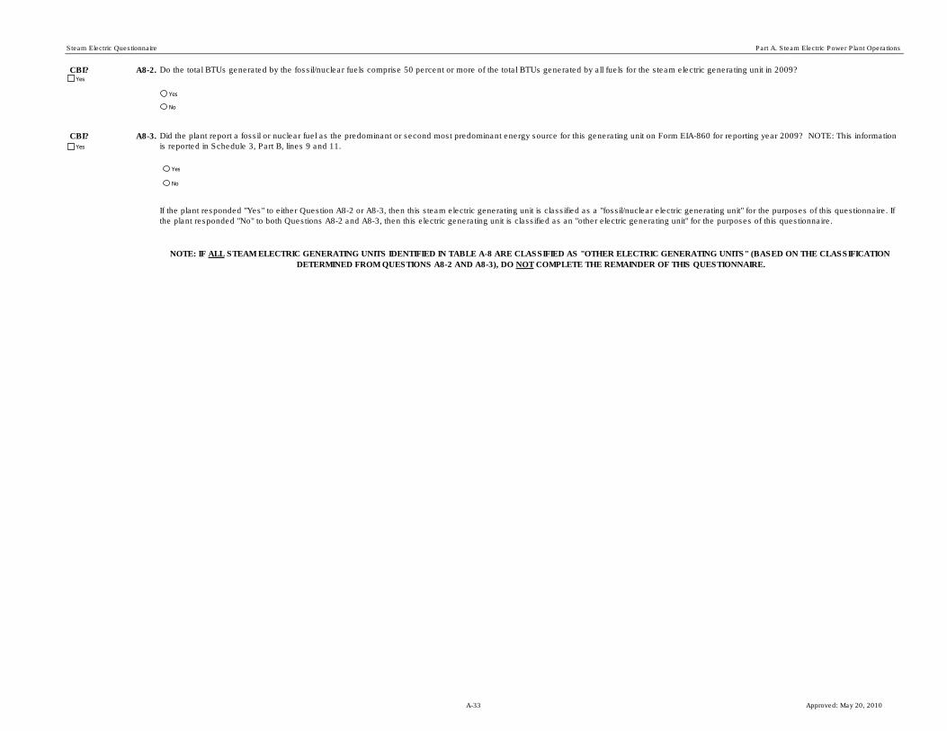
Steam Electric Questionnaire Part A. Steam Electric Power Plant Operations
CBI? A8-2.
CBI? A8-3.
Do the total BTUs generated by the fossil/nuclear fuels comprise 50 percent or more of the total BTUs generated by all fuels for the steam electric generating unit in 2009?
Did the plant report a fossil or nuclear fuel as the predominant or second most predominant energy source for this generating unit on Form EIA-860 for reporting year 2009? NOTE: This information
is reported in Schedule 3, Part B, lines 9 and 11.
NOTE: IF ALL STEAM ELECTRIC GENERATING UNITS IDENTIFIED IN TABLE A-8 ARE CLASSIFIED AS "OTHER ELECTRIC GENERATING UNITS" (BASED ON THE CLASSIFICATION
DETERMINED FROM QUESTIONS A8-2 AND A8-3), DO NOT COMPLETE THE REMAINDER OF THIS QUESTIONNAIRE.
If the plant responded "Yes" to either Question A8-2 or A8-3, then this steam electric generating unit is classified as a "fossil/nuclear electric generating unit" for the purposes of this questionnaire. If
the plant responded "No" to both Questions A8-2 and A8-3, then this electric generating unit is classified as an "other electric generating unit" for the purposes of this questionnaire.
Yes
Yes
No
Yes
No
Yes
A-33 Approved: May 20, 2010

Steam Electric Questionnaire Part A. Steam Electric Power Plant Operations
Plant ID: Insert Plant ID
Plant Name: Insert Plant Name
Part: A
Section Title: 9. NOx Control Systems
Instructions:
CBI? A9-1.
(Complete Table A-12)
Month Year Month Year Month Year
Date of Next
Planned SCR
Catalyst
Replacement or
RegenerationType of NOx Control
System
Did the plant operate any NOx control systems on fossil-fueled electric generating units after January 1, 2009 or is the plant currently constructing/installing or
planning to construct/install any NOx control system on fossil-fueled electric generating units by December 31, 2020? See Part A Section 8 for unit
classifications.
(Skip to Section 10)
Date of Last SCR
Catalyst
Replacement or
Regeneration
Throughout Section 9 (Questions A9-1 to A9-11), provide information for all NOx control systems operated on fossil-fueled electric generating units on or
after January 1, 2009 and all NOx control systems the plant is currently constructing/installing or planning to construct/install on fossil-fueled electric
generating units by December 31, 2020. See Part A Section 8 for unit classifications. You will need to indicate the steam electric generating units that are
serviced by these air pollution control systems. Use codes from Table A-8 or Table A-9 to designate the SE Unit ID.
In Table A-12, provide information for NOx control systems that the plant operated after January 1, 2009, is currently constructing/installing, or planning to
construct/install by December 31, 2020 on each operating or planned fossil-fueled electric generating unit (identified in Table A-8 or Table A-9). Provide the
steam electric generating unit ID (use codes from Table A-8 or Table A-9), the type of NOx control system(s) operating or planned for the steam electric
generating unit, whether the NOx control system(s) are operating or planned, and the date the NOx control was/will be installed. In addition, for the steam
electric generating units serviced by a SCR system, identify the date and location (i.e., on- or off-site) of the last and next SCR catalyst
replacement/regeneration.
SE Unit ID
Status of
NOx
Control
System
Where Last
SCR Catalyst
Regeneration
Occurred
Where Next SCR
Catalyst
Regeneration is
Planned to Occur
Table A-12. NOx Control Systems
For Steam Electric Generating Units Serviced by a SCR System
Date of Installation,
Previous or Planned
Yes
Yes
No
SCR
SNCR
Overfire Air
Low NOx burners
Other:
Operating/Planned
Operating/Planned
Operating/Planned
Operating/Planned
Operating/Planned
Month
Last Month Last Year
Last Replaced/Regenerated
Month
Month
Month
Month
Planned Month
Planned Replaced/Regenerated
Last Onsite/Offsite Planned Onsite/Offsite
SCR
SNCR
Overfire Air
Low NOx burners
Other:
Operating/Planned
Operating/Planned
Operating/Planned
Operating/Planned
Operating/Planned
Month
Last Month
Last Replaced/Regenerated
Month
Month
Month
Month
Planned Month
Planned Replaced/Regenerated
Last Onsite/Offsite Planned Onsite/Offsite
Last Year
Planned Year
Planned Year
SE Unit ID
SE Unit ID
A-34 Approved: May 20, 2010

Steam Electric Questionnaire Part A. Steam Electric Power Plant Operations
CBI? A9-2.
StateCompany Name Telephone NumberCity
Table A-13. Companies that performed the last two SCR catalyst regenerations
If the plant has sent an SCR catalyst off site for regeneration, provide the company name, location, and phone number for the company(ies) that performed
the last two SCR catalyst regenerations .
State
State
Plant did not send SCR catalyst offsite for regeneration.
Yes
SCR
SNCR
Overfire Air
Low NOx burners
Other:
Operating/Planned
Operating/Planned
Operating/Planned
Operating/Planned
Operating/Planned
Month
Last Month
Last Replaced/Regenerated
Month
Month
Month
Month
Planned Month
Planned Replaced/Regenerated
Last Onsite/Offsite Planned Onsite/Offsite
SCR
SNCR
Overfire Air
Low NOx burners
Other:
Operating/Planned
Operating/Planned
Operating/Planned
Operating/Planned
Operating/Planned
Month
Last Month
Last Replaced/Regenerated
Month
Month
Month
Month
Planned Month
Planned Replaced/Regenerated
Last Onsite/Offsite Planned Onsite/Offsite
SCR
SNCR
Overfire Air
Low Nox burners
Other:
Operating/Planned
Operating/Planned
Operating/Planned
Operating/Planned
Operating/Planned
Month
Last Month
Last Replaced/Regenerated
Month
Month
Month
Month
Planned Month
Planned Replaced/Regenerated
Last Onsite/Offsite Planned Onsite/Offsite
SCR
SNCR
Overfire Air
Low NOx burners
Other:
Operating/Planned
Operating/Planned
Operating/Planned
Operating/Planned
Operating/Planned
Month
Last Month
Last Replaced/Regenerated
Month
Month
Month
Month
Planned Month
Planned Replaced/Regenerated
Last Onsite/Offsite Planned Onsite/Offsite
SCR
SNCR
Overfire Air
Low NOx burners
Other:
Operating/Planned
Operating/Planned
Operating/Planned
Operating/Planned
Operating/Planned
Month
Last Month
Last Replaced/Regenerated
Month
Month
Month
Month
Planned Month
Planned Replaced/Regenerated
Last Onsite/Offsite Planned Onsite/Offsite
SCR
SNCR
Overfire Air
Low NOx burners
Other:
Operating/Planned
Operating/Planned
Operating/Planned
Operating/Planned
Operating/Planned
Month
Last Month
Last Replaced/Regenerated
Month
Month
Month
Month
Planned Month
Planned Replaced/Regenerated
Last Onsite/Offsite Planned Onsite/Offsite
Last Year Planned Year
Last Year Planned Year
Last Year Planned Year
Last Year Planned Year
Last Year Planned Year
Last Year Planned Year
SE Unit ID
SE Unit ID
SE Unit ID
SE Unit ID
SE Unit ID
SE Unit ID
A-35 Approved: May 20, 2010

Steam Electric Questionnaire Part A. Steam Electric Power Plant Operations
CBI? A9-3.
(Continue)
CBI? A9-4.
gpy times every year(s)
CBI? A9-5.
CBI? A9-6.
CBI? A9-7.
(Continue)
(Skip to Question A9-7)
(Skip to Question A9-7)
(Skip to Section 10)
Is the SCR catalyst washed on site?
Indicate all intermediate and final destination(s) of the SCR catalyst regeneration wastewater. If the plant recycles the SCR catalyst regeneration wastewater,
indicate the plant process to which this water is recycled. [Check all that apply].
If the SCR catalyst is regenerated on site, indicate whether process wastewater is generated from the regeneration process.
Provide the typical volume of SCR catalyst regeneration wastewater generated (gpy) and the frequency at which the process wastewater is generated.
Is the SCR catalyst regeneration wastewater commingled with other wastewaters? If yes, indicate the wastewaters with which the SCR catalyst regeneration
wastewater is commingled. [Check all boxes that apply.]
Yes
No
NA: SCR catalyst is NOT regenerated on site
Fly ash transport water
Bottom ash transport water
FGD scrubber purge
Cooling tower blowdown
Once-through cooling water
Cleaning wastes from cleaning metal process equipment
Other, specify:
Settling pond
Chemical precipitation
Constructed wetlands
pH adjustment Other, specify:
Yes
Yes
Yes
Immediately recycled back to plant process. Please describe how the process wastewater is reused:
Yes
Yes
No
Yes
Yes
No
Transferred to on-site treatment system. Identify the type of treatment system below. [Check all boxes that apply.]
Discharged to surface water. Provide NPDES permitted outfall number (from Part A Section 2.2):
Indirect discharge to a publicly or privately owned treatment works
Other, explain:
A-36 Approved: May 20, 2010

Steam Electric Questionnaire Part A. Steam Electric Power Plant Operations
CBI? A9-8. Is process wastewater generated from the SCR catalyst washing process?
(Continue)
CBI? A9-9.
gpy times every year(s)
CBI? A9-10.
CBI? A9-11.
(Skip to Section 10)
Is the SCR catalyst washing wastewater commingled with other wastewaters? If yes, indicate the wastewaters with which the SCR catalyst washing
wastewater is commingled. [Check all boxes that apply.]
Provide the typical volume of SCR catalyst washing wastewater generated (gpy) and the frequency at which the process wastewater is
generated.
Indicate all intermediate and final destination(s) of the SCR catalyst washing wastewater. If the plant recycles the SCR catalyst washing wastewater, indicate
the plant process to which this water is recycled. [Check all that apply].
Fly ash transport water
Bottom ash transport water
FGD scrubber purge
Cooling tower blowdown
Once-through cooling water
Cleaning wastes from cleaning metal process equipment
Other, specify:
Yes
Yes
Yes
No
Yes
Yes
Yes
No
Settling pond
Chemical precipitation
Constructed wetlands
pH adjustment Other, specify:
Immediately recycled back to plant process. Please describe how the process wastewater is reused:
Transferred to on-site treatment system. Identify the type of treatment system below. [Check all boxes that apply.]
Discharged to surface water. Provide NPDES permitted outfall number (from Part A Section 2.2):
Indirect discharge to a publicly or privately owned treatment works
Other, explain:
A-37 Approved: May 20, 2010

Steam Electric Questionnaire Part A. Steam Electric Power Plant Operations
Plant ID: Insert Plant ID
Plant Name: Insert Plant Name
Part: A
Section Title: 10. Flue Gas Mercury Control Systems
Instructions:
CBI? A10-1.
(Complete Table A-14)
Month Year
Currently Operating Flue Gas Mercury Control Systems
FGMC-1
Other:
(Skip to Question A10-3)
Date of Installation,
Previous or Planned
Steam Electric Units
that Exhaust to the
System (Check all
boxes that apply)
Are there any flue gas mercury control systems (other than FGD, SCR/SNCR, or particulate matter control systems ) installed on
fossil-fueled electric generating units or is the plant currently constructing/installing or planning to construct/install any flue gas
mercury control systems on fossil-fueled electric generating units by December 31, 2020? See Part A Section 8 for unit
classifications.
Table A-14. Flue Gas Mercury Control Systems
Throughout Section 10 (Questions A10-1 to A10-5), provide information for all flue gas mercury control systems (including those
not currently operating) that are currently installed on fossil-fueled electric generating units and all systems the plant is currently
constructing/installing or planning to construct/install on fossil-fueled electric generating units by December 31, 2020. See Part A
Section 8 for unit classifications. Do NOT include FGD, SCR/SNCR, and particulate matter control systems . You will need to
indicate the steam electric generating units that are serviced by these air pollution control systems. Use codes from Table A-8 or
Table A-9 to designate the SE Unit ID.
In Table A -14 provide information for all flue gas mercury control systems (other than FGD, SCR/SNCR, or particulate matter
control systems) currently installed on fossil-fueled electric generating units (including those not currently operating) and all systems
the plant is currently constructing/installing or planning to construct/install on fossil-fueled electric generating units by December 31,
2020. Provide the type of mercury control system and the generating units that are or will be serviced by the system. [Check all
boxes that apply.] For planned mercury control systems, provide the type of system it will be and all generating units that will be
serviced by the system.
Mercury
Control
Systems
Type of
Mercury
Control
System
Location of
Mercury Control
System in
Relation to Initial
Particulate Matter
Control System
Handling of
Mercury
Control Solid
Waste
Design or
Targeted
Mercury
Removal
Efficiency
(%)
Yes
Yes
No
SE Unit 1 SE Unit 6 Month Upstream/Downstream Wet/Dry
SE Unit 2
SE Unit 3
SE Unit 4
SE Unit 8
SE Unit 9
SE Unit 7
SE Unit 5 SE Unit 10
A-38 Approved: May 20, 2010

Steam Electric Questionnaire Part A. Steam Electric Power Plant Operations
FGMC-2
Other:
FGMC-3
Other:
FGMC-4
Other:
Planned Flue Gas Mercury Control Systems
FGMC-A
Other:
FGMC-B
Other:
FGMC-C
Other:
Month Upstream/Downstream Wet/Dry
Month Upstream/Downstream Wet/Dry
Month Upstream/Downstream Wet/Dry
Month Upstream/Downstream Wet/Dry
Month Upstream/Downstream Wet/Dry
Month Upstream/Downstream Wet/Dry
SE Unit 1
SE Unit 2
SE Unit 3
SE Unit 4
SE Unit 1
SE Unit 2
SE Unit 3
SE Unit 4
SE Unit 1
SE Unit 2
SE Unit 3
SE Unit 4
SE Unit 1
SE Unit 2
SE Unit 3
SE Unit 4
SE Unit 1
SE Unit 2
SE Unit 3
SE Unit 4
SE Unit 1
SE Unit 2
SE Unit 3
SE Unit 4
SE Unit 6
SE Unit 8
SE Unit 9
SE Unit 7
SE Unit 5 SE Unit 10
SE Unit 6
SE Unit 8
SE Unit 9
SE Unit 7
SE Unit 5 SE Unit 10
SE Unit 6
SE Unit 8
SE Unit 9
SE Unit 7
SE Unit 5 SE Unit 10
SE Unit 6
SE Unit 8
SE Unit 9
SE Unit 7
SE Unit 5 SE Unit 10
SE Unit 6
SE Unit 8
SE Unit 9
SE Unit 7
SE Unit 5 SE Unit 10
SE Unit 6
SE Unit 8
SE Unit 9
SE Unit 7
SE Unit 5 SE Unit 10
A-39 Approved: May 20, 2010

Steam Electric Questionnaire Part A. Steam Electric Power Plant Operations
CBI? A10-2.
CBI? A10-3.
(Continue)
Specify the type(s) of technology studied:
CBI? A10-4
(Continue)
CBI? A10-5
Company Name:
Start Date: End Date:
(Skip to Section 11)
(Skip to Section 11)
In the space below, provide a description of all flue gas mercury control system processes, the plant is currently operating, currently
constructing/installing, or planning to construct/install by December 31, 2020. Include the solid wastes and process wastewater
streams generated, the volume and characteristics (i.e., pollutants present) of the process wastewater generated, and any known
or anticipated probable effect on other process wastewater (e.g., fly ash transport water). Additionally, indicate how the solid wastes
and process wastewater from mercury control systems are/will be handled (e.g., are solid wastes combined with fly ash). Provide
the final destination of all mercury control system wastes (e.g., sent to an ash pond or other impoundment, landfilled, or hauled off
site).
Has the plant ever operated or does it plan to operate a pilot-scale flue gas mercury control system for a pilot study evaluation?
Provide the name of the company whose technology was/will be tested, the start and end date of the pilot study, and attach the
final technical evaluation report from the pilot study (if study is complete).
Did the study evaluate process wastewaters generated by the technology or identify that process wastewater will be generated or
affected by the technology?
Yes
Yes
Yes
No
I have attached the final technical evaluation report.
I did not attach the final technical evaluation report. Explain why:
Yes
Yes
No
Yes
A-40 Approved: May 20, 2010

Steam Electric Questionnaire Part A. Steam Electric Power Plant Operations
Plant ID: Insert Plant ID
Plant Name: Insert Plant Name
Part: A
Section Title: 11. Carbon Capture Systems
Instructions:
CBI? A11-1.
(Complete Table A-15)
(Skip to Section 12)
Month Year
Currently Operating Carbon Capture Systems
CCS-1
Other:
CCS-2
Other:
Table A-15. Carbon Capture Systems
Full Scale or
Pilot Scale
Percent of Flue
Gas Treated
Throughout Section 11 (Questions A11-1 to A11-6), provide information for all carbon capture systems operated on fossil-fueled electric generating
units on or after January 1, 2009 and all systems the plant is currently constructing/installing or planning to construct/install on fossil-fueled electric
generating units by December 31, 2020. See Part A Section 8 for unit classifications. Provide this information for both full-scale and pilot-scale
systems. You will need to indicate the steam electric generating units that are serviced by these air pollution control systems. Use codes from Table
A-8 or Table A-9 to designate the SE Unit ID.
Did the plant operate any carbon capture systems on fossil-fueled electric generating units after January 1, 2009 or is the plant currently
constructing/installing or planning to construct/install any carbon capture systems on fossil-fueled electric generating units by December 31, 2020?
See Part A Section 8 for unit classifications.
In Table A-15 provide information for carbon capture systems that the plant operated after January 1, 2009 on fossil-fueled electric generating units
at the plant and systems that the plant is currently constructing/installing or planning to construct/install on fossil-fueled electric generating units by
December 31, 2020. Provide the type of carbon capture system and the steam electric generating units that correspond to the system. [Check all
boxes that apply.] For planned carbon capture systems, provide the type of system it will be and all steam electric generating units that will
correspond to the system.
Date of Installation, Previous
or Planned
CCS Systems
Type of Carbon
Capture System
Steam Electric Units
Corresponding to the
System (Check all boxes
that apply).
Yes
Month
Month
SE Unit 1 SE Unit 6
SE Unit 2
SE Unit 3
SE Unit 4
SE Unit 8
SE Unit 9
SE Unit 7
SE Unit 1 SE Unit 6
SE Unit 2
SE Unit 3
SE Unit 4
SE Unit 8
SE Unit 9
SE Unit 7
Full Scale
Pilot Scale
Full Scale
Pilot Scale
Yes
No
SE Unit 5 SE Unit 10
SE Unit 5 SE Unit 10
A-41 Approved: May 20, 2010

Steam Electric Questionnaire Part A. Steam Electric Power Plant Operations
CCS-3
Other:
CCS-4
Other:
Planned Carbon Capture Systems
CCS-A
Other:
CCS-B
Other:
CCS-C
Other:
CBI? A11-2. In the space below, provide a description of all full-scale and pilot-scale carbon capture system processes, previously tested, previously operated,
currently operating, currently being constructed/installed, and/or planned to constructed/installed by December 31, 2020. Provide a general
description of the system, including the specific list of types of chemicals and equipment used, the types of process wastewater generated, and any
known or anticipated probable effect on other process wastewater streams (e.g., fly ash transport water). Additionally, indicate how the process
wastewater streams from the carbon capture process were/will be managed.
Yes
Month
Month
Month
Month
Month
SE Unit 1 SE Unit 6
SE Unit 2
SE Unit 3
SE Unit 4
SE Unit 8
SE Unit 9
SE Unit 7
SE Unit 1 SE Unit 6
SE Unit 2
SE Unit 3
SE Unit 4
SE Unit 8
SE Unit 9
SE Unit 7
SE Unit 1 SE Unit 6
SE Unit 2
SE Unit 3
SE Unit 4
SE Unit 8
SE Unit 9
SE Unit 7
SE Unit 1 SE Unit 6
SE Unit 2
SE Unit 3
SE Unit 4
SE Unit 8
SE Unit 9
SE Unit 7
SE Unit 1 SE Unit 6
SE Unit 2
SE Unit 3
SE Unit 4
SE Unit 8
SE Unit 9
SE Unit 7
Full Scale
Pilot Scale
Full Scale
Pilot Scale
Full Scale
Pilot Scale
Full Scale
Pilot Scale
Full Scale
Pilot Scale
SE Unit 5 SE Unit 10
SE Unit 5 SE Unit 10
SE Unit 5 SE Unit 10
SE Unit 5 SE Unit 10
SE Unit 5 SE Unit 10
A-42 Approved: May 20, 2010

Steam Electric Questionnaire Part A. Steam Electric Power Plant Operations
CBI? A11-3.
(Continue)
(Skip to Section 12)
CBI? A11-4.
Company Name:
Start Date: End Date:
CBI? A11-5.
gpm hpd dpy
CBI? A11-6.
(Continue)
(Skip to Section 12)
Has the plant operated any full-scale or pilot-scale carbon capture systems for studies in which process wastewaters generated by the technology
were evaluated?
Provide the name of the company whose technology was tested, the start and end date of the study, and attach the final technical evaluation report
from the study (if study is complete).
Were characterization samples of the carbon capture wastewater collected during the study?
Provide the typical volume of process wastewater generated from the carbon capture system (gpm) and the duration (hpd) and frequency (dpy) of
carbon capture wastewater generation.
Provide the analytical results of the carbon capture wastewater characterization (if not already included in the technical report requested in Question
A11-4).
I have attached the final technical evaluation report.
I did not attach the final technical evaluation report. Explain why:
Yes
Yes
No
Yes
Yes
Yes
Yes
No
I have attached the analytical results of the carbon capture wastewater characterization.
I did not attach the analytical results of the carbon capture wastewater characterization. Explain why:
A-43 Approved: May 20, 2010

Steam Electric Questionnaire Part A. Steam Electric Power Plant Operations
Plant ID: Insert Plant ID
Plant Name: Insert Plant Name
Part: A
Section Title: 12. Wet Electrostatic Precipitator Systems
Instructions:
CBI? A12-1.
(Complete Table A-16)
Month Year
Currently Operating Wet ESP Systems
WESP-1
Other:
Table A-16. Wet Electrostatic Precipitator Systems
Wet ESP
System IDs
Steam Electric Units
Corresponding to the
System (Check all boxes
that apply).
Date of Installation,
Previous or Planned
Location of Wet ESP System
Full Scale or
Pilot Scale
Percent of Flue
Gas Treated
Throughout Section 12, provide information for all wet electrostatic precipitator (ESP) systems operated on fossil-fueled electric generating units
on or after January 1, 2009 and all systems the plant is currently constructing/installing or planning to construct/install on fossil-fueled electric
generating units by December 31, 2020. See Part A Section 8 for unit classifications. Provide this information for both full-scale and pilot-scale
systems. You will need to indicate the steam electric generating units that are serviced by these air pollution control systems. Use codes from
Table A-8 or Table A-9 to designate the SE Unit ID.
Did the plant operate any wet ESP systems on fossil-fueled electric generating units after January 1, 2009 or is the plant currently
constructing/installing or planning to construct/install any wet ESP systems on fossil-fueled electric generating units by December 31, 2020?
See Part A Section 8 for unit classifications.
In Table A-16 provide information for wet ESP systems that the plant operated after January 1, 2009 that service fossil-fueled electric generating
units and systems that the plant is currently constructing/installing or planning to construct/install to service fossil-fueled electric generating units
by December 31, 2020. Provide the steam electric generating units that correspond to the system, the date the system was/is planned to be
installed, the location of the system, whether it is a full-scale or pilot-scale system, and if it is a pilot-scale system, the percent of flue gas that is
treated.
(Skip to Section 13)
Yes
Yes
No
SE Unit 1 SE Unit 6
SE Unit 2
SE Unit 3
SE Unit 4
SE Unit 8
SE Unit 9
SE Unit 7Full Scale
Pilot Scale
Yes
Yes
No
Immediately downstream of dry ESP
Immediately downstream of baghouse
Immediately downstream of wet FGD
Other (Explain below):
Month
SE Unit 5 SE Unit 10
A-44 Approved: May 20, 2010

Steam Electric Questionnaire Part A. Steam Electric Power Plant Operations
WESP-2
Other:
WESP-3
Other:
WESP-4
Other:
Planned Wet ESP Systems
WESP-A
Other:
WESP-B
Other:
WESP-C
Other:
CBI? A12-2.
gpm
hpd
dpy
Provide the flow rate, duration, and frequency of the wastewater generated from the wet ESP system for calendar year 2009.
SE Unit 1 SE Unit 6
SE Unit 2
SE Unit 3
SE Unit 4
SE Unit 8
SE Unit 9
SE Unit 7
SE Unit 1 SE Unit 6
SE Unit 2
SE Unit 3
SE Unit 4
SE Unit 8
SE Unit 9
SE Unit 7
SE Unit 1 SE Unit 6
SE Unit 2
SE Unit 3
SE Unit 4
SE Unit 8
SE Unit 9
SE Unit 7
SE Unit 1 SE Unit 6
SE Unit 2
SE Unit 3
SE Unit 4
SE Unit 8
SE Unit 9
SE Unit 7
SE Unit 1 SE Unit 6
SE Unit 2
SE Unit 3
SE Unit 4
SE Unit 8
SE Unit 9
SE Unit 7
SE Unit 1 SE Unit 6
SE Unit 2
SE Unit 3
SE Unit 4
SE Unit 8
SE Unit 9
SE Unit 7
Full Scale
Pilot Scale
Full Scale
Pilot Scale
Full Scale
Pilot Scale
Full Scale
Pilot Scale
Full Scale
Pilot Scale
Full Scale
Pilot Scale
Yes
Immediately downstream of dry ESP
Immediately downstream of baghouse
Immediately downstream of wet FGD
Other (Explain below):
Immediately downstream of dry ESP
Immediately downstream of baghouse
Immediately downstream of wet FGD
Other (Explain below):
Immediately downstream of dry ESP
Immediately downstream of baghouse
Immediately downstream of wet FGD
Other (Explain below):
Immediately downstream of dry ESP
Immediately downstream of baghouse
Immediately downstream of wet FGD
Other (Explain below):
Immediately downstream of dry ESP
Immediately downstream of baghouse
Immediately downstream of wet FGD
Other (Explain below):
Immediately downstream of dry ESP
Immediately downstream of baghouse
Immediately downstream of wet FGD
Other (Explain below):
Month
Month
Month
Month
Month
Month
SE Unit 5 SE Unit 10
SE Unit 5 SE Unit 10
SE Unit 5 SE Unit 10
SE Unit 5 SE Unit 10
SE Unit 5 SE Unit 10
SE Unit 5 SE Unit 10
A-45 Approved: May 20, 2010

Steam Electric Questionnaire Part A. Steam Electric Power Plant Operations
CBI? A12-3.
Other process wastewater, specify:
CBI? A12-4.
ppm
%
CBI? A12-5.
For water sources that may be used in the wet ESP (e.g., fresh intake, recycled process water), indicate the maximum chlorides concentration
and maximum solids percentage that is acceptable for the water to be used for those purposes. Identify any other criteria that the source water
must meet.
Indicate all intermediate and final destination(s) of the wet ESP wastewater. If the plant recycles the wet ESP wastewater, indicate the plant
process to which this water is recycled. [Check all that apply].
Provide the source of the water used in the wet ESP system. [Check all boxes that apply.]
Raw intake water
Intake water that has been treated on site prior to use
Process wastewater, specify
Other, explain:
Yes
Yes
Process Wastewaters
Indirect discharge to a publicly or privately owned treatment works
Immediately recycled back to plant process. Please describe how the wet ESP wastewater is reused:
Discharged to surface water. Provide NPDES permitted outfall number (from Part A Section 2.2):
Deep well injection
Other, explain:
Transferred to treatment system reported in Tables D-1 or D-2. Identify the type of treatment system below. [Check all boxes that apply.]
Settling pond
Biological reactor – aerobic
Mechanical vapor compression (brine concentrator)
Mechanical vapor compression (brine concentrator) with spray dryer
Chemical precipitation
Biological reactor – anoxic/anaerobic
Mechanical vapor compression (brine concentrator) with crystallizer
Other, explain:
Constructed wetlands
Chlorides concentration:
Solids percentage:
Other, explain:
Yes
Transferred to solid separation process. Identify the type of solid separation process below. [Check all boxes that apply.]
Dewatering bin Hydrocyclones
Centrifuges Filters
Other (Explain):
A-46 Approved: May 20, 2010

Steam Electric Questionnaire Part A. Steam Electric Power Plant Operations
CBI? A12-6.
(Continue)
CBI? A12-7.
Company Name:
Start Date: End Date:
CBI? A12-8.
(Continue)
Provide the name of the company whose technology was tested, the start and end date of the study, and attach the final technical evaluation
report from the study (if study is complete).
Were characterization samples of the wet ESP wastewater collected during the study?
Has the plant operated any full-scale or pilot-scale wet ESP systems for studies in which process wastewaters generated by the technology were
evaluated?
Provide the analytical results of the wet ESP wastewater characterization (if not already included in the technical report requested in Question
A12-7).
(Skip to Section 13)
(Skip to Section 13)
I have attached the final technical evaluation report.
I did not attach the final technical evaluation report. Explain why:
Yes
Yes
No
Yes
Yes
Yes
No
I have attached the analytical results of the wet ESP wastewater characterization.
I did not attach the analytical results of the wet ESP wastewater characterization. Explain why:
A-47 Approved: May 20, 2010

Steam Electric Questionnaire Part A. Steam Electric Power Plant Operations
Plant ID: Insert Plant ID
Plant Name: Insert Plant Name
Part: A
Section Title: 13. Coal Storage and Processing
Instructions:
CBI? A13-1.
CBI? A13-2.
gpy number of days of discharge in 2009
Throughout Section 13 (Questions A13-1 to A13-17), provide information regarding the storage, processing,
and use of coal for all steam electric generating units that were operated in 2009. Please provide all free
response answers in the highlighted yellow areas.
(Continue)
(Skip to Question A13-16)
Did the plant store or process any coal on site in 2009? Processing coal includes any methods used to
prepare the coal for use at the plant including but not limited to crushing/pulverizing coal.
Provide the amount (gpy) and number of days of discharge of coal pile runoff in 2009. If there was no coal
pile runoff discharge, enter “0” and provide the reason in the Comments tab. The plant can estimate
discharge of coal pile runoff, but a description of the estimation method must be included in the Comments
tab.
Yes
No
Yes
A-48 Approved: May 20, 2010

Steam Electric Questionnaire Part A. Steam Electric Power Plant Operations
CBI? A13-3.
(Continue)
Minimum: S.U.
Maximum: S.U.
Median: S.U.
CBI? A13-4. Is coal pile runoff transferred to a pond/impoundment?
If yes, provide the pH range for the coal pile runoff generated at the plant (prior to any commingling with
other water streams, including other stormwater).
Was the coal pile runoff monitored for pH?
pH in coal pile runoff:
(Skip to Question A13-4)
Yes
Yes
Yes
No
Segregated - specify pond/impoundment unit ID(s) from Table A-4:
Commingled - specify pond/impoundment unit ID(s) from Table A-4:
Yes, transferred to a pond/impoundment
No
A-49 Approved: May 20, 2010
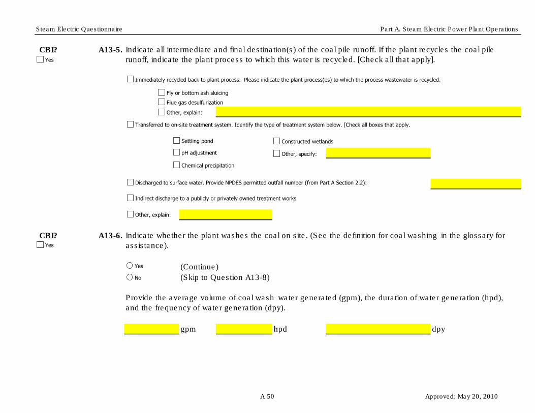
Steam Electric Questionnaire Part A. Steam Electric Power Plant Operations
CBI? A13-5.
CBI? A13-6.
(Continue)
gpm hpd dpy
Indicate all intermediate and final destination(s) of the coal pile runoff. If the plant recycles the coal pile
runoff, indicate the plant process to which this water is recycled. [Check all that apply].
Indicate whether the plant washes the coal on site. (See the definition for coal washing in the glossary for
assistance).
(Skip to Question A13-8)
Provide the average volume of coal wash water generated (gpm), the duration of water generation (hpd),
and the frequency of water generation (dpy).
Fly or bottom ash sluicing
Flue gas desulfurization
Other, explain:
Yes
No
Yes
Yes
Immediately recycled back to plant process. Please indicate the plant process(es) to which the process wastewater is recycled.
Other, explain:
Settling pond
Chemical precipitation
Constructed wetlands
pH adjustment Other, specify:
Transferred to on-site treatment system. Identify the type of treatment system below. [Check all boxes that apply.]
Discharged to surface water. Provide NPDES permitted outfall number (from Part A Section 2.2):
Indirect discharge to a publicly or privately owned treatment works
A-50 Approved: May 20, 2010

Steam Electric Questionnaire Part A. Steam Electric Power Plant Operations
CBI? A13-7. Indicate all intermediate and final destination(s) of the coal wash water. If the plant recycles the coal wash
water, indicate the plant process to which this water is recycled. [Check all that apply].
Fly or bottom ash sluicing
Flue gas desulfurization
Other, explain:
Yes
Immediately recycled back to plant process. Please indicate the plant process(es) to which the wastewater is recycled.
Other, explain:
Settling pond
Chemical precipitation
Constructed wetlands
Biological reactor - aerobic
Other, specify:
Transferred to on-site treatment system. Identify the type of treatment system below. [Check all boxes that apply.]
Discharged to surface water. Provide NPDES permitted outfall number (from Part A Section 2.2):
Indirect discharge to a publicly or privately owned treatment works
Biological reactor - anoxic/anaerobic
Transferred to pond(s)/impoundment(s). Provide the IDs of the pond/impoundment unit(s) previously defined in Table A-4:
A-51 Approved: May 20, 2010
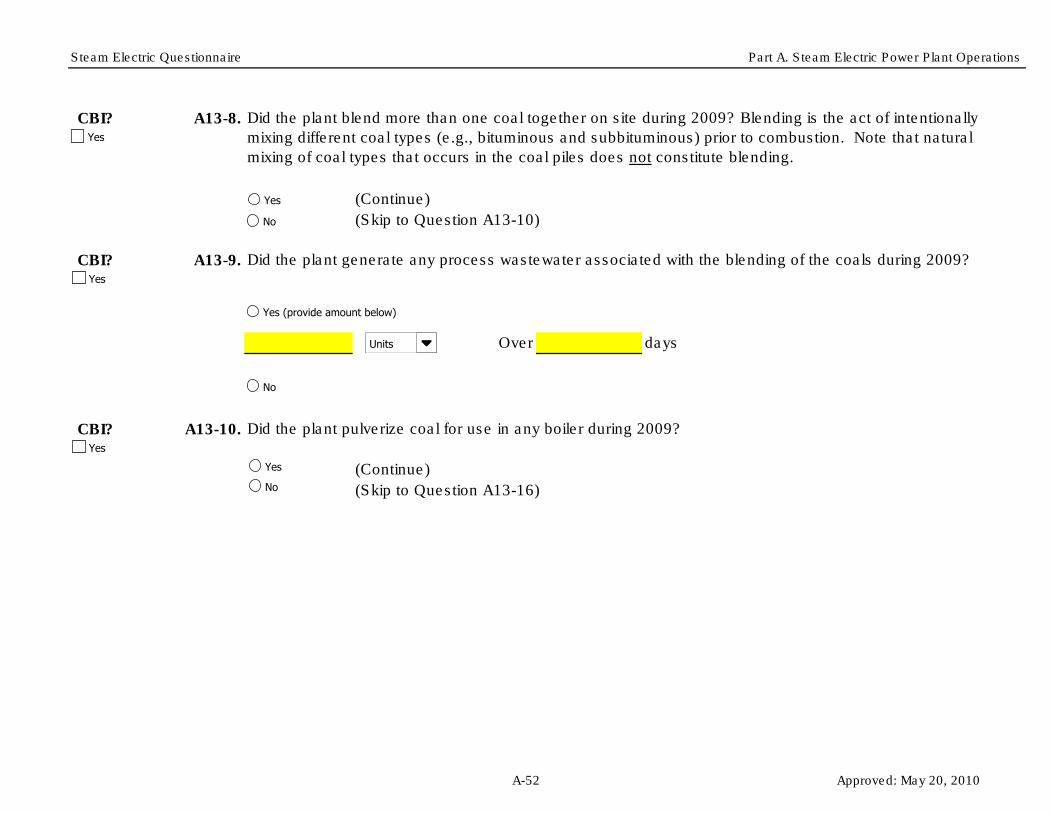
Steam Electric Questionnaire Part A. Steam Electric Power Plant Operations
CBI? A13-8.
(Continue)
CBI? A13-9.
Over days
CBI? A13-10. Did the plant pulverize coal for use in any boiler during 2009?
(Continue)
(Skip to Question A13-16)
(Skip to Question A13-10)
Did the plant blend more than one coal together on site during 2009? Blending is the act of intentionally
mixing different coal types (e.g., bituminous and subbituminous) prior to combustion. Note that natural
mixing of coal types that occurs in the coal piles does not constitute blending.
Did the plant generate any process wastewater associated with the blending of the coals during 2009?
Yes
No
Yes (provide amount below)
No
Units
Yes
Yes
Yes
Yes
No
A-52 Approved: May 20, 2010

Steam Electric Questionnaire Part A. Steam Electric Power Plant Operations
CBI? A13-11.
(Continue)
Over days
CBI? A13-12.
(Continue)
Over days
CBI? A13-13.
(Skip to Question A13-12)
Was any water used in the coal pulverization process, other than that used for sluicing mill rejects?
Were mill rejects sluiced in 2009?
Provide the volume of mill rejects sluice water generated in 2009 (gpd OR gpy) and the frequency of sluice
water generation (days).
Were the mill rejects sluiced separately or were they sluiced with fly and/or bottom ash?
Provide the volume of coal pulverization process wastewater generated in 2009 (gpd OR gpy) and the
frequency of this process wastewater generation (days).
(Skip to Question A13-14)
Units
Sluiced by
Yes
Yes
Yes
No
Yes
Yes
No
Units
A-53 Approved: May 20, 2010

Steam Electric Questionnaire Part A. Steam Electric Power Plant Operations
CBI? A13-14. Are the mill rejects pyritic?
CBI? A13-15.
tpd
tpd
tpd
tpd
CBI? A13-16.
CBI? A13-17. Is the plant currently operating, currently constructing/installing, or planning to construct/install by December
31, 2015 an IGCC generating unit that was not in operation during 2009?
Indicate how mill rejects are disposed of and provide amount(s). If the mill rejects are sent to a
pond/impoundment, indicate whether they are combined with fly and/or bottom ash. [Check all boxes that
apply.]
Did the plant gasify coal, petroleum coke, or oil to operate an IGCC generating unit during 2009?
Stored in/transferred to a pond/impoundment reported in Table A-4
Combined with fly ash in pond/impoundment
Combined with bottom ash in pond/impoundment
Not combined with fly or bottom ash in pond/impoundment
Stored in/transferred to a landfill reported in Table A-6
Hauled off site for disposal
Other, explain:
Yes
Yes
Yes
Yes
Yes
No
Unknown
Yes
No
Yes
No
A-54 Approved: May 20, 2010

Steam Electric Questionnaire Part A. Steam Electric Power Plant Operations
Plant ID: Insert Plant ID
Plant Name: Insert Plant Name
Part: A
Section Title: Part A Comments
Instructions:
Question Number
CBI?
CBI?
CBI?
CBI?
CBI?
CBI?
CBI?
CBI?
CBI?
CBI?
CBI?
Cross reference your comments by question number and indicate the confidential status of your comment by checking the box
next to “Yes” under "CBI?" (Confidential Business Information).
Comment
Yes
Yes
Yes
Yes
Yes
Yes
Yes
Yes
Yes
Yes
Yes
A-55 Approved: May 20, 2010

Steam Electric Questionnaire Part A. Steam Electric Power Plant Operations
CBI?
CBI?
CBI?
CBI?
CBI?
CBI?
CBI?
CBI?
CBI?
CBI?
CBI?
CBI?
CBI?
CBI?
CBI?
Yes
Yes
Yes
Yes
Yes
Yes
Yes
Yes
Yes
Yes
Yes
Yes
Yes
Yes
Yes
A-56 Approved: May 20, 2010

Steam Electric Questionnaire Part A. Steam Electric Power Plant Operations
CBI?
CBI?
CBI?
CBI?
CBI?
CBI?
CBI?
CBI?
Yes
Yes
Yes
Yes
Yes
Yes
Yes
Yes
A-57 Approved: May 20, 2010

Steam Electric Questionnaire Part A. Steam Electric Power Plant Operations
Table A-17. Listing of Fossil-Type Fuels
Type of Fuel
Coal
Anthracite Coal
Bituminous Coal
Lignite Coal
Subbituminous Coal
Waste Coal (including anthracite culm, bituminous gob)
Other Coal
Coal Synfuel
Oil
Distillate Fuel Oil (including Diesel, No. 1, No. 2, and No. 4 fuel oils)
Jet Fuel
Kerosene
Residual Fuel Oil (including No. 5 and No. 6 fuel oil and Bunker C fuel oil)
Other Oil (Crude oil, liquid butane, liquid propane, re-refined motor oil, sludge oil, tar
oil, other petroleum-based liquid wastes)
Waste Oil
Petroleum Coke
Petroleum Coke
Gas
Blast Furnace Gas
Natural Gas
Gaseous Propane
Other Gases (Define on “Comments Page”, NOT including landfill gas or biomass gas)
Approved: May 20, 2010

Steam Electric Questionnaire Part A. Steam Electric Power Plant Operations
Air heater cleaning water AHCW
Ash pile runoff APR Effluent - 1 EFF-1
Boiler blowdown BB Effluent - 2 EFF-2
Boiler fireside cleaning water BFCW Effluent - 3 EFF-3
Boiler tube cleaning water BTCW Effluent - 4 EFF-4
Bottom ash sluice BAS Effluent - 5 EFF-5
Carbon capture wastewater CCAPW Effluent - 6 EFF-6
Coal pile runoff CPR Filter backwash FltBW
Combined ash sluice CAS Sludge SLDG
Combustion turbine cleaning (combustion gas portion of
turbine) water
COMBCW
Combustion turbine cleaning (compressor portion of the
turbine) water
COMPRCW POND-1 Effluent POND-1-EFF
Combustion turbine evaporative coolers blowdown TECB POND-2 Effluent POND-2-EFF
Cooling tower blowdown CTB POND-3 Effluent POND-3-EFF
FGD scrubber purge SCRBP POND-4 Effluent POND-4-EFF
FGD slurry blowdown FGDB POND-5 Effluent POND-5-EFF
Filter Backwash FLTBW POND-6 Effluent POND-6-EFF
Floor drain wastewater FDW POND-7 Effluent POND-7-EFF
Flue gas mercury control system wastewater FGMCW POND-8 Effluent POND-8-EFF
Fly ash sluice FAS POND-9 Effluent POND-9-EFF
General runoff GR POND-10 Effluent POND-10-EFF
Gypsum pile runoff GPR POND-A Effluent POND-A-EFF
Gypsum wash water GYPWW POND-B Effluent POND-B-EFF
Ion exchange wastewater IXW POND-C Effluent POND-C-EFF
Landfill runoff - capped landfill LRC WWT-1 Effluent WWT-1-EFF
Landfill runoff - uncapped landfill LRUC WWT-2 Effluent WWT-2-EFF
Leachate LEACH WWT-3 Effluent WWT-3-EFF
Limestone pile runoff LPR WWT-4 Effluent WWT-4-EFF
Mill reject sluice MRS WWT-5 Effluent WWT-5-EFF
Steam Electric Questionnaire Code Tables
For Use as Effluents from Pond/Impoundment Systems
and/or Wastewater Treatment Systems in Part D, Table D-4.
Process Wastewaters Treated Wastewaters
For Use in Tables and Questions throughout Parts A, B, C, D, and F.
For Use as Influents to Pond/Impoundment Systems and/or
Wastewater Treatment Systems in Part D, Table D-3, AND
Recycled Waters Throughout Questionnaire.
Approved: May 20, 2010

Steam Electric Questionnaire Part A. Steam Electric Power Plant Operations
Steam Electric Questionnaire Code Tables
Once -through cooling water CW WWT-6 Effluent WWT-6-EFF
Reverse osmosis reject water RORW WWT-A Effluent WWT-A-EFF
SCR catalyst regeneration wastewater SCRRW WWT-B Effluent WWT-B-EFF
SCR catalyst washing wastewater SCRWW WWT-C Effluent WWT-C-EFF
Soot blowing wash water SOOTW
Steam turbine cleaning water STCW
Yard drain wastewater YARDW
Process Wastewaters
For Use in Tables and Questions throughout Parts A, B, C, D, and F.
For Use as Influents to Pond/Impoundment Systems and/or
Wastewater Treatment Systems in Part D, Table D-3, AND
Recycled Waters Throughout Questionnaire.
Treated Wastewaters
Approved: May 20, 2010

Steam Electric Questionnaire Part A. Steam Electric Power Plant Operations
Steam Electric Questionnaire Code Tables
Adsorptive media ADSORB Burned on site BURNAerobic Biological Reactor AERBIO Deep-well injection DWELL
Anaerobic Biological Reactor ANBIO Discharge to POTW POTW
Aerobic/Anaerobic Biological Reactor AER/ANBIO Discharge to PrOTW PrOTW
Chemical Precipitation Reaction Tank 1 - 1 CP-1-1 Discharge to surface water SW
Chemical Precipitation Reaction Tank 1 - 2 CP-1-2 Evaporation EVAP
Chemical Precipitation Reaction Tank 2 - 1 CP-2-1 Hauled off site for reuse
(removal fee)
HAULR - RF
Chemical Precipitation Reaction Tank 2 - 2 CP-2-2 Hauled off site for reuse (given
away)
HAULR - GA
Chemical Precipitation Reaction Tank 3 - 1 CP-3-1 Hauled off site for reuse
(marketed and sold)
SOLD
Chemical Precipitation Reaction Tank 3 - 2 CP-3-2 Hauled off site for disposal HAUL
Clarification, Primary - 1 CL-P-1 Mixed with fly ash for disposal MFA
Clarification, Primary - 2 CL-P-2 On-site landfill (as reported in
Table A-6)
LANDF
Clarification, Secondary - 1 CL-S-1 POND-1 POND-1
Clarification, Secondary - 2 CL-S-2 POND-2 POND-2
Clarification, Tertiary - 1 CL-T-1 POND-3 POND-3
Clarification, Tertiary - 2 CL-T-2 POND-4 POND-4
Constructed wetland - Cell 1 CWL -1 POND-5 POND-5
Constructed wetland - Cell 2 CWL -2 POND-6 POND-6
Constructed wetland - Cell 3 CWL -3 POND-7 POND-7
Constructed wetland - Cell 4 CWL -4 POND-8 POND-8
Constructed wetland - Cell 5 CWL -5 POND-9 POND-9
Constructed wetland - Cell 6 CWL -6 POND-10 POND-10
Constructed wetland system CWTS POND-A POND-A
Equalization, Primary EQ-P POND-B POND-B
Equalization, Secondary EQ-S POND-C POND-C
Filter, Microfiltration - 1 FLT-M-1 WWT-1 WWT-1
Filter, Microfiltration - 2 FLT-M-2 WWT-2 WWT-2
Wastewater Treatment Units Destinations
For Use in Tables and Questions Throughout Parts A, C, D,
and F.For Use in Tables and Questions Throughout Parts D and F.
Approved: May 20, 2010

Steam Electric Questionnaire Part A. Steam Electric Power Plant Operations
Steam Electric Questionnaire Code Tables
Filter, Microfiltration - 3 FLT-M-3 WWT-3 WWT-3
Filter, Microfiltration - 4 FLT-M-4 WWT-4 WWT-4
Filter, Sand/Gravity - 1 FLT-S-1 WWT-5 WWT-5
Filter, Sand/Gravity - 2 FLT-S-2 WWT-6 WWT-6
Filter, Sand/Gravity - 3 FLT-S-3 WWT-A WWT-AFilter, Sand/Gravity - 4 FLT-S-4 WWT-B WWT-B
Filter, Ultrafiltration - 1 FLT-U-1 WWT-C WWT-C
Filter, Ultrafiltration - 2 FLT-U-2 Reuse as boiler water RECYC - BW
Filter, Ultrafiltration - 3 FLT-U-3 Reuse as bottom ash sluice RECYC - BAS
Filter, Ultrafiltration - 4 FLT-U-4 Reuse as combined ash sluice RECYC - CAS
Filter press - 1 FP-1 Reuse as FGD slurry
preparation water
RECYC - FGDP
Filter press - 2 FP-2 Reuse as FGD absorber
makeup
RECYC - FGDAB
Holding tank HT Reuse as fly ash sluice RECYC - FAS
Ion exchange IX Reuse as mill reject sluice RECYC - MRS
Natural wetlands NW Reuse in cooling towers RECYC - CW
pH adjustment - 1 PH-1
pH adjustment - 2 PH-2
pH adjustment - 3 PH-3
Reverse osmosis ROS
Pond Unit - 1 SPD-1
Pond Unit - 2 SPD-2
Pond Unit - 3 SPD-3
Pond Unit - 4 SPD-4
Pond Unit - 5 SPD-5
Pond Unit - 6 SPD-6
Pond Unit - 7 SPD-7
Pond Unit - 8 SPD-8
Pond Unit - 9 SPD-9
Wastewater Treatment Units Destinations
For Use in Tables and Questions Throughout Parts D and F.For Use in Tables and Questions Throughout Parts A, C, D,
and F.
Approved: May 20, 2010

Steam Electric Questionnaire Part A. Steam Electric Power Plant Operations
Steam Electric Questionnaire Code Tables
Pond Unit - 10 SPD-10Centrifuge - 1 CENT-1
Pond Unit - 11 SPD-11 Centrifuge - 2 CENT-2Pond Unit - 12 SPD-12 Centrifuge - 3 CENT-3Pond Unit - 13 SPD-13 Centrifuge - 4 CENT-4Pond Unit - 14 SPD-14 Hydrocyclones - 1 HYC-1
Settling tank - 1 ST-1 Hydrocyclones - 2 HYC-2
Settling tank - 2 ST-2 Hydrocyclones - 3 HYC-3
Settling tank - 3 ST-3 Hydrocyclones - 4 HYC-4
Settling tank - 4 ST-4 Filter press - 1 FP-1
Settling tank - 5 ST-5 Filter press - 2 FP-2
Thickener - 1 TH-1 Thickener - 1 TH-1
Thickener - 2 TH-2 Thickener - 2 TH-2
Vacuum drum filter - 1 VF-1 Vacuum drum filter - 1 VF-1
Vacuum drum filter - 2 VF-2 Vacuum drum filter - 2 VF-2
Vacuum filter belt - 1 VFB-1 Vacuum filter belt - 1 VFB-1
Vacuum filter belt - 2 VFB-2 Vacuum filter belt - 2 VFB-2
Solids HandlingWastewater Treatment Units
For Use in Tables and Questions Throughout Parts D and F.For Use as Planned Solids Handling for the FGD Slurry
Blowdown in Part B Table B-2.
Approved: May 20, 2010
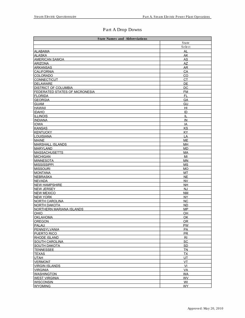
Steam Electric Questionnaire Part A. Steam Electric Power Plant Operations
State
Select
ALAKASAZARCACOCTDEDCFMFLGAGUHIIDILINIAKSKYLAMEMHMDMAMIMNMSMOMTNENVNHNJNMNYNCNDMPOHOKORPWPAPRRISCSDTNTXUTVTVIVAWAWVWIWY
Part A Drop Downs
WEST VIRGINIAWISCONSINWYOMING
State Names and Abbreviations
VERMONTVIRGIN ISLANDSVIRGINIA WASHINGTON
SOUTH DAKOTATENNESSEETEXASUTAH
PENNSYLVANIAPUERTO RICORHODE ISLANDSOUTH CAROLINA
OHIOOKLAHOMAOREGONPALAU
NEW YORKNORTH CAROLINANORTH DAKOTANORTHERN MARIANA ISLANDS
NEVADANEW HAMPSHIRENEW JERSEYNEW MEXICO
MISSISSIPPIMISSOURIMONTANANEBRASKA
MARYLANDMASSACHUSETTSMICHIGANMINNESOTA
KENTUCKYLOUISIANAMAINEMARSHALL ISLANDS
ILLINOISINDIANAIOWAKANSAS
GEORGIAGUAM HAWAIIIDAHO
DELAWAREDISTRICT OF COLUMBIAFEDERATED STATES OF MICRONESIAFLORIDA
ARKANSASCALIFORNIA COLORADO CONNECTICUT
ALABAMAALASKAAMERICAN SAMOAARIZONA
Approved: May 20, 2010

Steam Electric Questionnaire Part A. Steam Electric Power Plant Operations
Units
Units
Select
gpd
gpy
Sluiced by
Sluiced by
Select
Sluiced separately
Sluiced with fly ash
Sluiced with bottom ash
Sluiced with fly ash and bottom ash
Yes/No
Yes/No
Select
Yes
No
am/pm
am/pm
Select
am
pm
Month
Month
Select
January
February
March
April
May
June
July
August
September
October
November
December
Planned Month
Planned Month
Select
January
February
March
April
May
June
July
August
September
October
November
December
Unknown
Approved: May 20, 2010

Steam Electric Questionnaire Part A. Steam Electric Power Plant Operations
Last Month
Last Month
Select
January
February
March
April
May
June
July
August
September
October
November
December
N/A
Year
Year
Select
1980
1981
1982
1983
1984
1985
1986
1987
1988
1989
1990
1991
1992
1993
1994
1995
1996
1997
1998
1999
2000
2001
2002
2003
2004
2005
2006
2007
2008
2009
2010
2011
2012
2013
2014
2015
2016
2017
2018
2019
2020
New Unit Year
New Unit Year
Select
2010
2011
2012
Approved: May 20, 2010

Steam Electric Questionnaire Part A. Steam Electric Power Plant Operations
2013
2014
2015
Planned Year
Planned Year
Select
2010
2011
2012
2013
2014
2015
2016
2017
2018
2019
2020
Unknown
Last Year
Last Year
Select
1980
1981
1982
1983
1984
1985
1986
1987
1988
1989
1990
1991
1992
1993
1994
1995
1996
1997
1998
1999
2000
2001
2002
2003
2004
2005
2006
2007
2008
2009
2010
N/A
Type of Receiving Water
Type of Receiving Water
Select
Estuary
Great Lakes
Lake/Pond
Reservoir
River/Stream
Other
Approved: May 20, 2010

Steam Electric Questionnaire Part A. Steam Electric Power Plant Operations
Process Wastewaters
Process Wastewaters
Select
Air heater cleaning water
Ash pile runoff
Boiler blowdown
Boiler fireside cleaning water
Boiler tube cleaning water
Bottom ash sluice
Carbon capture wastewater
Coal pile runoff
Combined ash sluice
Combustion turbine cleaning (combustion gas portion of
turbine) water
Combustion turbine cleaning (compressor portion of the
turbine) water
Combustion turbine evaporative coolers blowdown
Cooling tower blowdown
FGD scrubber purge
FGD slurry blowdown
Filter Backwash
Floor drain wastewater
Flue gas mercury control system wastewater
Fly ash sluice
General runoff
Gypsum pile runoff
Gypsum wash water
Ion exchange wastewater
Landfill runoff - capped landfill
Landfill runoff - uncapped landfill
Leachate
Limestone pile runoff
Mill reject sluice
Once -through cooling water
Reverse osmosis reject water
SCR catalyst regeneration wastewater
SCR catalyst washing wastewater
Soot blowing wash water
Steam turbine cleaning water
Yard drain wastewater
Other
Pond/Impoundment Unit ID
Pond/Impoundment Unit ID
Select
SPD-1
SPD-2
SPD-3
SPD-4
SPD-5
SPD-6
SPD-7
SPD-8
SPD-9
SPD-10
SPD-11
SPD-12
SPD-13
SPD-14
RET-SPD-1
RET-SPD-2
RET-SPD-3
RET-SPD-4
SPD-A
SPD-B
SPD-C
SPD-D
SPD-E
Approved: May 20, 2010

Steam Electric Questionnaire Part A. Steam Electric Power Plant Operations
Landfill ID
Landfill ID
Select
LANDFILL-1
LANDFILL-2
LANDFILL-3
LANDFILL-4
RET-LANDFILL-1
RET-LANDFILL-2
RET-LANDFILL-3
RET-LANDFILL-4
LANDFILL-A
LANDFILL-B
LANDFILL-C
LANDFILL-D
Type of Turbine
Type of Turbine
Select
Combined Cycle
Stand-Alone Steam Turbine
Type of Cooling System
Type of Cooling System
Select
Dry Cooling
Once-Through
Recirculating
Other, specify below
SCR Catalyst Wastewater Handled
SCR Catalyst Wastewater Handled
Select
Transferred to pond and/or wastewater treatment system
Transferred to pond or holding basin without discharge
Hauled off site
Discharged without treatment
Other (specify below)
Operating/Planned
Operating/Planned
Select
Operating
Planned
Last Replaced/Regenerated
Last Replaced/Regenerated
Select
Replaced
Regenerated
Not replaced/regenerated
Planned Replaced/Regenerated
Planned Replaced/Regenerated
Select
Replaced
Regenerated
Unknown
Approved: May 20, 2010

Steam Electric Questionnaire Part A. Steam Electric Power Plant Operations
Last Onsite/Offsite
Last Onsite/Offsite
Select
Onsite
Offsite
Not regenerated
Planned Onsite/Offsite
Planned Onsite/Offsite
Select
Onsite
Offsite
Unknown
Upstream/Downstream
Upstream/Downstream
Select
Upstream
Downstream
Wet/Dry
Wet/Dry
Select
Wet
Dry
SE Unit ID
SE Unit ID
Select
SE Unit-1
SE Unit-2
SE Unit-3
SE Unit-4
SE Unit-5
SE Unit-6
SE Unit-7
SE Unit-8
SE Unit-9
SE Unit-10
SE Unit-A
SE Unit-B
SE Unit-C
SE Unit-D
Approved: May 20, 2010

OMB Control Number: 2040-0281 Plant ID: Insert Plant IDApproval Expires: 05/31/2013 Plant Name: Insert Plant Name
Section Title Tab Name
Part B Instructions Part B InstructionsGeneral FGD System Information Part B Section 1Planned FGD System Information Part B Section 2FGD Additive Information Part B Section 3Wet FGD System Information Part B Section 4FGD Solids Disposition and Marketing for Wet FGD Systems Part B Section 4 TablesFGD Wastewater Generation Part B Section 5FGD Monitoring Data Instructions Part B Section 6FGD Monitoring Data Part B Section 6 TableFGD Wastewater Treatment Part B Section 7Dry FGD System Information Part B Section 8FGD Solids Disposition and Marketing for Dry FGD Systems Part B Section 8 TablesPart B Comments Part B Comments
Code TablesSteam Electric Questionnaire Code Tables
Steam Electric Questionnaire
PART B - FLUE GAS DESULFURIZATION (FGD) SYSTEMS
Table of Contents
Approved: May 20, 2010

Steam Electric Questionnaire Part B. Instructions
Plant ID: Insert Plant IDPlant Name: Insert Plant Name
PART B. FLUE GAS DESULFURIZATION (FGD) SYSTEMS
Use the Part B Comments tab to do the following: provide additional information as requested in certain questions within Part B; indicate atypical data (e.g., if 2009 information is not representative of normal operations); and note methods used to make best engineering estimates in the event that exact data are not available.
Throughout Part B, information is requested on FGD systems that are under construction/installation or planned to be constructed/installed by December 31, 2020. Provide design information, or best engineering estimates as necessary, for these planned systems.
As you are completing the electronic form, note the following: When you enter your plant name and plant ID on the Part B Table of Contents tab, all name and ID fields throughout Part B will automatically populate. Refer to the overall questionnaire instructions, the glossary, and the acronym list for assistance with completing Part B.
INSTRUCTIONS
Part B requests information about flue gas desulfurization (FGD) systems that are located at the plant or are planned to be located at the plant. Complete Part B if you operate one or more FGD systems, or if you are currently constructing/installing or planning to construct/install one or more FGD systems by December 31, 2020.
Please provide all free response answers in the highlighted yellow areas. Throughout Part B, you may need to make copies of certain sections/questions for multiple FGD systems. Instructions are provided throughout Part B regarding making copies. Note that system ID fields must be populated on the copied tab or section, located in the upper right corner under "Plant ID" and "Plant Name", in order to correlate the requested information with the correct system.
Approved: May 20, 2010

Steam Electric Questionnaire Part B. Flue Gas Desulfurization (FGD) Systems
Plant ID:Plant Name:
Part: BSection Title: 1. General FGD System Information
Instructions:
CBI? B1-1.
(Continue)
(Skip to next Questionnaire Part)
CBI? B1-2.
Part B requests information about flue gas desulfurization (FGD) systems that are located at the plant or are planned to be located at the plant that are used to service fossil-fueled electric generating units. See Part A Section 8 for unit classifications. Complete Part B if you operate one or more FGD systems , or if you are currently constructing/installing or planning to construct/install one or more FGD systems by December 31, 2020, to service fossil-fueled electric generating units.
Figure B-1. Example Recirculation Wet FGD Scrubber System Diagram
Insert Plant IDInsert Plant Name
Does the plant operate one or more flue gas desulfurization (FGD) systems that service fossil-fueled steam electric generating units, or is the plant currently constructing/installing or planning to construct/install one or more FGD systems to service fossil-fueled steam electric generating units by December 31, 2020?
Complete Table B-1 for each FGD system that the plant operates that services fossil-fueled electric generating units, or is currently constructing/installing or planning to construct/install to service fossil-fueled electric generating units by December 31, 2020. Assign an FGD system ID to each FGD system using the drop down menu provided. Assign the FGD systems sequentially using the numbered IDs (e.g., FGD-1, FGD-2) for the systems currently operating. Assign the FGD systems sequentially using the lettered IDs (e.g., FGD-A, FGD-B) for the systems that are planned to operate. Enter the date the system initially began operation or is planned to begin operation. Identify each steam electric unit (currently operating or planned units) that is serviced by each FGD system using the codes EPA assigned to steam electric units in Table A-8 and/or Table A-9. Identify the type of oxidation performed in the FGD system for all wet FGD systems (Note: mark "Not Applicable" for dry FGD systems). Also provide the design or actual sulfur dioxide removal efficiency for each FGD system.
Wet FGD systems capture sulfur dioxide from the flue gas using a wet slurry that generates a process wastewater that exits the scrubber absorber, shown as FGD slurry blowdown in Figure B-1 for recirculation scrubbers, or as FGD slurry discharge in Figure B-2 for single pass scrubbers. Indicate for each FGD system if FGD slurry blowdown (or FGD slurry discharge) is generated.
Use the drop down boxes to identify the type of FGD system and to specify the type(s) of sorbents used in the system. If a sorbent used is not provided in the drop down, identify "other" and provide the type(s) of sorbent in the yellow highlighted box to the right.
Yes
Yes
No
Yes
B-1 Approved: May 20, 2010

Steam Electric Questionnaire Part B. Flue Gas Desulfurization (FGD) Systems
Figure B-2. Example Single Pass Wet FGD Scrubber System Diagram
B-2 Approved: May 20, 2010

Steam Electric Questionnaire Part B. Flue Gas Desulfurization (FGD) Systems
Date System Initially Brought
On Line, or Planned to be
Brought On Line(month/year)
Steam Electric Units from Table A-8 and/or A-9 Serviced by This FGD
System [check all boxes that apply]
Does (or Will) the System Generate a
FGD Slurry Blowdown (or Slurry Discharge) Stream
(i.e., is it a wet system)?
Type of Oxidation (Forced,
Natural, or Inhibited)
Type of FGD System
Sulfur Dioxide Removal
Efficiency(%)
Primary:
01/1995 Secondary: 97.5
Tertiary:
Quaternary:
Primary:
Secondary:
Tertiary:
Quaternary:
Primary:
Secondary:
Tertiary:
Quaternary:
Primary:
Secondary:
Tertiary:
Quaternary:
Primary:
Secondary:
Tertiary:
Quaternary:
Primary:
Secondary:
Tertiary:
Quaternary:
Primary:
Secondary:
Tertiary:
Quaternary:
Primary:
Secondary:
Tertiary:
Quaternary:
Primary:
Secondary:
Tertiary:
Quaternary:
Example:
Table B-1. FGD Systems in Operation or Planning to be Operated by December 31, 2020
Type of SorbentFGD System ID
Spray
Forced
Inhibited
Natural
Not Applicable
Yes
NoFGD-1
SE Unit 1
SE Unit 2
SE Unit 3
SE Unit 4
SE Unit 5
SE Unit 8
SE Unit 9
SE Unit 7
SE Unit 6 SE Unit A
SE Unit B
SE Unit C
SE Unit D
Limestone
Soda Ash
Not Applicable
Not Applicable
Type of FGD System
Forced
Inhibited
Natural
Not Applicable
Yes
NoFGD System ID
Type of Sorbent
Type of Sorbent
Type of Sorbent
Type of Sorbent
Type of FGD System
Forced
Inhibited
Natural
Not Applicable
Yes
NoFGD System ID
Type of Sorbent
Type of Sorbent
Type of Sorbent
Type of Sorbent
Type of FGD System
Forced
Inhibited
Natural
Not Applicable
Yes
NoFGD System ID
Type of Sorbent
Type of Sorbent
Type of Sorbent
Type of Sorbent
Type of FGD System
Forced
Inhibited
Natural
Not Applicable
Yes
NoFGD System ID
Type of Sorbent
Type of Sorbent
Type of Sorbent
Type of Sorbent
Type of FGD System
Forced
Inhibited
Natural
Not Applicable
Yes
NoFGD System ID
Type of Sorbent
Type of Sorbent
Type of Sorbent
Type of Sorbent
Type of FGD System
Forced
Inhibited
Natural
Not Applicable
Yes
NoFGD System ID
Type of Sorbent
Type of Sorbent
Type of Sorbent
Type of Sorbent
Type of FGD System
Forced
Inhibited
Natural
Not Applicable
Yes
NoFGD System ID
Type of Sorbent
Type of Sorbent
Type of Sorbent
Type of Sorbent
Type of FGD System
Forced
Inhibited
Natural
Not Applicable
Yes
NoFGD System ID
Type of Sorbent
Type of Sorbent
Type of Sorbent
Type of Sorbent
SE Unit 10
SE Unit 1
SE Unit 2
SE Unit 3
SE Unit 4
SE Unit 5
SE Unit 8
SE Unit 9
SE Unit 7
SE Unit 6 SE Unit A
SE Unit B
SE Unit C
SE Unit DSE Unit 10
SE Unit 1
SE Unit 2
SE Unit 3
SE Unit 4
SE Unit 5
SE Unit 8
SE Unit 9
SE Unit 7
SE Unit 6 SE Unit A
SE Unit B
SE Unit C
SE Unit DSE Unit 10
SE Unit 1
SE Unit 2
SE Unit 3
SE Unit 4
SE Unit 5
SE Unit 8
SE Unit 9
SE Unit 7
SE Unit 6 SE Unit A
SE Unit B
SE Unit C
SE Unit DSE Unit 10
SE Unit 1
SE Unit 2
SE Unit 3
SE Unit 4
SE Unit 5
SE Unit 8
SE Unit 9
SE Unit 7
SE Unit 6 SE Unit A
SE Unit B
SE Unit C
SE Unit DSE Unit 10
SE Unit 1
SE Unit 2
SE Unit 3
SE Unit 4
SE Unit 5
SE Unit 8
SE Unit 9
SE Unit 7
SE Unit 6 SE Unit A
SE Unit B
SE Unit C
SE Unit DSE Unit 10
SE Unit 1
SE Unit 2
SE Unit 3
SE Unit 4
SE Unit 5
SE Unit 8
SE Unit 9
SE Unit 7
SE Unit 6 SE Unit A
SE Unit B
SE Unit C
SE Unit DSE Unit 10
SE Unit 1
SE Unit 2
SE Unit 3
SE Unit 4
SE Unit 5
SE Unit 8
SE Unit 9
SE Unit 7
SE Unit 6 SE Unit A
SE Unit B
SE Unit C
SE Unit DSE Unit 10
SE Unit 1
SE Unit 2
SE Unit 3
SE Unit 4
SE Unit 5
SE Unit 8
SE Unit 9
SE Unit 7
SE Unit 6 SE Unit A
SE Unit B
SE Unit C
SE Unit DSE Unit 10
B-3 Approved: May 20, 2010

Steam Electric Questionnaire Part B. Flue Gas Desulfurization (FGD) Systems
Plant ID: Insert Plant IDPlant Name: Insert Plant Name
Part: BSection Title:
Instructions:
CBI? B2-1.
Maximum (gpm)
24-Hour Daily
Average (gpm)
Example HYC-1, VFB-1 EQ-P, CP-1-1, CL-P-1, PH-1, FLT-S-1
1,200 1,000 06/2012
a – This question refers to the blowdown solids handling, not the treatment system solids handling.
Complete Table B-2 for each FGD system under construction/installation or planned to be constructed/installed by December 31, 2020 that is reported in Table B-1 and is expected to generate FGD slurry blowdown. Enter the planned method for handling solids generated, whether FGD scrubber purge (or slurry discharge ) will be generated, the type of wastewater treatment system, the design maximum and 24-hour daily average flow rate for the treatment system, and the date the treatment system will be brought on line. Use codes from the Code Tables tab, as appropriate, and separate multiple entries with commas. If you do not know the type of wastewater treatment system that will be installed or the flow rate of the treatment system, enter "Unknown" into the appropriate columns in the table.
Throughout this section, provide information for all FGD systems under construction/installation or planned to be constructed/installed by December 31, 2020 that are reported in Table B-1 and are expected to generate FGD slurry blowdown . Please provide all free response answers in the highlighted yellow areas.
2. Planned FGD System Information
Table B-2. FGD Systems Planned or Under Construction/Installation
Type of Wastewater Treatment System
Planned to Treat FGD Scrubber Purge (or Slurry
Discharge) (See Wastewater Treatment
Units Table in Code Tables Tab)
Design Flow Rate for FGD Treatment System
Estimated Date the New FGD Treatment System
Will be Brought On Line (or Date FGD Scrubber Purge (or Slurry Discharge) Will be Transferred to Existing
System)(month/year)FGD System ID
Planned Solids Handling for the FGD Slurry
Blowdown (See Solids Handling Table in Code
Tables Tab) a
Will System Generate
FGD Scrubber Purge (or
Slurry Discharge)?
Will FGD Scrubber Purge
(or Slurry Discharge) be
Treated by New or Existing Treatment
System
Yes
New
FGD System ID (Planned)
FGD System ID (Planned)
FGD System ID (Planned)
FGD System ID (Planned)
FGD System ID (Planned)
FGD System ID (Planned)
Yes/No
FGD-A
New/Existing
New/Existing
New/Existing
New/Existing
New/Existing
New/Existing
Yes
Yes/No
Yes/No
Yes/No
Yes/No
Yes/No
B-4 Approved: May 20, 2010

Steam Electric Questionnaire Part B. Flue Gas Desulfurization (FGD) Systems
Plant ID: Insert Plant IDPlant Name: Insert Plant Name
Part: BSection Title: 3. FGD Additive Information
Instructions:
CBI? B3-1.
AdditiveFGD System(s) in which Additive is Used or
is Planned to be Used
Sodium thiosulfate
Throughout this section, provide information for all FGD Systems listed in Table B-1. Please provide all free response answers in the highlighted yellow areas.
In Table B-3, indicate the additive(s) used or planned to be used in each FGD system listed in Table B-1, and provide a description of its purpose. [Check all boxes that apply.]
Table B-3. FGD Additive Information
Purpose of Additive
Adipic acid
Elemental sulfur
Dibasic acid (DBA)
Formic acid
Organosulfide
Yes
FGD 1
FGD 2
FGD 3
FGD 4
FGD 5
FGD 6
FGD A
FGD B
FGD C
Increase sulfur dioxide removal Increase mercury removal
Inhibit oxidation of FGD solids Scale inhibitor
Defoaming agent
Other (specify below):
FGD 1
FGD 2
FGD 3
FGD 4
FGD 5
FGD 6
FGD A
FGD B
FGD C
FGD 1
FGD 2
FGD 3
FGD 4
FGD 5
FGD 6
FGD A
FGD B
FGD C
FGD 1
FGD 2
FGD 3
FGD 4
FGD 5
FGD 6
FGD A
FGD B
FGD C
FGD 1
FGD 2
FGD 3
FGD 4
FGD 5
FGD 6
FGD A
FGD B
FGD C
Increase sulfur dioxide removal Increase mercury removal
Inhibit oxidation of FGD solids Scale inhibitor
Defoaming agent
Other (specify below):
Increase sulfur dioxide removal Increase mercury removal
Inhibit oxidation of FGD solids Scale inhibitor
Defoaming agent
Other (specify below):
Increase sulfur dioxide removal Increase mercury removal
Inhibit oxidation of FGD solids Scale inhibitor
Defoaming agent
Other (specify below):
Increase sulfur dioxide removal Increase mercury removal
Inhibit oxidation of FGD solids Scale inhibitor
Defoaming agent
Other (specify below):
FGD 1
FGD 2
FGD 3
FGD 4
FGD 5
FGD 6
FGD A
FGD B
FGD C
Increase sulfur dioxide removal Increase mercury removal
Inhibit oxidation of FGD solids Scale inhibitor
Defoaming agent
Other (specify below):
B-5 Approved: May 20, 2010

Steam Electric Questionnaire Part B. Flue Gas Desulfurization (FGD) Systems
Other (specify below):
Other (specify below):
None
FGD 1
FGD 2
FGD 3
FGD 4
FGD 5
FGD 6
FGD A
FGD B
FGD C
FGD 1
FGD 2
FGD 3
FGD 4
FGD 5
FGD 6
FGD A
FGD B
FGD C
FGD 1
FGD 2
FGD 3
FGD 4
FGD 5
FGD 6
FGD A
FGD B
FGD C
Increase sulfur dioxide removal Increase mercury removal
Inhibit oxidation of FGD solids Scale inhibitor
Defoaming agent
Other (specify below):
Increase sulfur dioxide removal Increase mercury removal
Inhibit oxidation of FGD solids Scale inhibitor
Defoaming agent
Other (specify below):
B-6 Approved: May 20, 2010

Steam Electric Questionnaire Part B. Flue Gas Desulfurization (FGD) Systems
Plant ID: Insert Plant IDPlant Name: Insert Plant Name
FGD System ID: Insert System ID
Part: BSection Title: 4. Wet FGD System Information
Instructions:
CBI? B4-1.
(Continue)
(Skip to Section 8)
CBI? B4-2.
Minimum operating concentration: ppm
Maximum operating concentration: ppm
Throughout this section, you will be required to provide information for each wet FGD system that the plant operates, reported in Table B-1. This section does not need to be completed for planned systems. Please provide all free response answers in the highlighted yellow areas.
Make copies of Section 4 and the Section 4 tables for each wet FGD system previously defined in Table B-1 using the "Copy Section 4 and Section 4 Tables" button below. Please note that you will create two new tabs for these sections. You may delete unneeded tabs, if accidently created. Enter the FGD system ID in the space provided above (use FGD system IDs assigned in Table B-1).
Did you report use of a FGD system that generates FGD slurry blowdown (i.e., wet system) in Table B-1?
Provide the operating concentration range of chlorides within the FGD scrubber absorber .
Copy Section 4 and Section 4 Tables
Yes
Yes
Yes
No
B-7 Approved: May 20, 2010
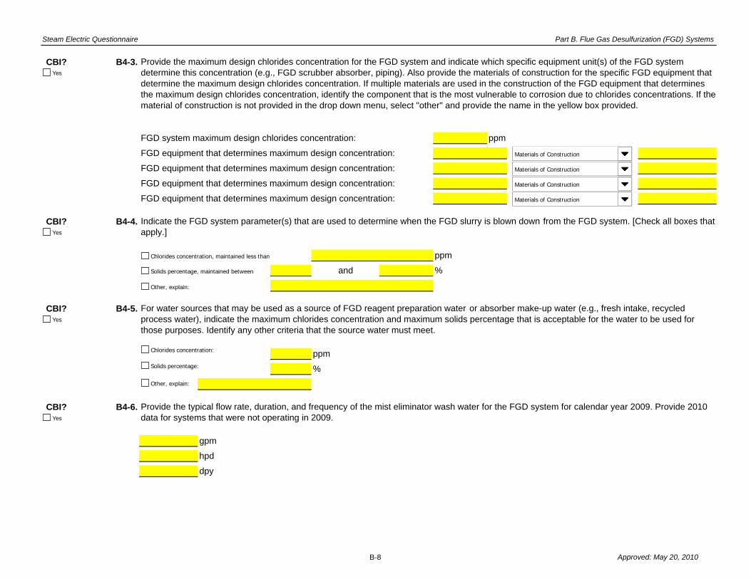
Steam Electric Questionnaire Part B. Flue Gas Desulfurization (FGD) Systems
CBI? B4-3.
FGD system maximum design chlorides concentration: ppm
FGD equipment that determines maximum design concentration:
FGD equipment that determines maximum design concentration:
FGD equipment that determines maximum design concentration:
FGD equipment that determines maximum design concentration:
CBI? B4-4.
ppm
and %
CBI? B4-5.
ppm
%
CBI? B4-6.
gpm
hpd
dpy
Provide the maximum design chlorides concentration for the FGD system and indicate which specific equipment unit(s) of the FGD system determine this concentration (e.g., FGD scrubber absorber, piping). Also provide the materials of construction for the specific FGD equipment that determine the maximum design chlorides concentration. If multiple materials are used in the construction of the FGD equipment that determines the maximum design chlorides concentration, identify the component that is the most vulnerable to corrosion due to chlorides concentrations. If the material of construction is not provided in the drop down menu, select "other" and provide the name in the yellow box provided.
Provide the typical flow rate, duration, and frequency of the mist eliminator wash water for the FGD system for calendar year 2009. Provide 2010 data for systems that were not operating in 2009.
Indicate the FGD system parameter(s) that are used to determine when the FGD slurry is blown down from the FGD system. [Check all boxes that apply.]
For water sources that may be used as a source of FGD reagent preparation water or absorber make-up water (e.g., fresh intake, recycled process water), indicate the maximum chlorides concentration and maximum solids percentage that is acceptable for the water to be used for those purposes. Identify any other criteria that the source water must meet.
Chlorides concentration, maintained less than
Solids percentage, maintained between
Other, explain:
Chlorides concentration:
Solids percentage:
Other, explain:
Yes
Materials of Construction
Yes
Yes
Yes
Materials of Construction
Materials of Construction
Materials of Construction
B-8 Approved: May 20, 2010

Steam Electric Questionnaire Part B. Flue Gas Desulfurization (FGD) Systems
CBI? B4-7.
gpm
hpd
dpy
CBI? B4-8.
gpm
hpd
dpy
CBI? B4-9.
gpm
hpd
dpy
CBI? B4-10. Provide the source of the mist eliminator wash water used. [Check all boxes that apply.] If the source is a process wastewater not provided in the dropdown box, select other and provide in the yellow box the name of the process wastewater and a short description.
Provide the typical flow rate, duration, and frequency of the absorber make-up water for the FGD system for calendar year 2009. Provide 2010 data for systems that were not operating in 2009.
Provide the typical flow rate, duration, and frequency of the FGD reagent preparation water for the FGD system for calendar year 2009. Provide 2010 data for systems that were not operating in 2009.
Provide the typical flow rate, duration, and frequency of the FGD reagent slurry for the FGD system for calendar year 2009. Provide 2010 data for systems that were not operating in 2009.
Raw intake water
Intake water that has been treated on site prior to use
Process wastewater
Other, explain:
Process Wastewater
Yes
Yes
Yes
Yes
B-9 Approved: May 20, 2010

Steam Electric Questionnaire Part B. Flue Gas Desulfurization (FGD) Systems
CBI? B4-11.
CBI? B4-12.
CBI? B4-13.
% FGD solids generated
% FGD solids generated
% FGD solids generated
% FGD solids generated
CBI? B4-14.
(Continue)
(Skip to Question B4-16)
Provide the source of the absorber make-up water used. [Check all boxes that apply.] If the source is a process wastewater not provided in the dropdown box, select other and provide in the yellow box the name of the process wastewater and a short description.
Provide the source of the FGD reagent preparation water used. [Check all boxes that apply.] If the source is a process wastewater not provided in the dropdown box, select other and provide in the yellow box the name of the process wastewater and a short description.
Indicate the type of solids that are generated within the FGD scrubber system. Also provide the approximate percent of the total FGD solids generated within the FGD system for each type (e.g., 85% calcium sulfate, 15% calcium sulfite).
Are the FGD solids combined with fly ash , bottom ash , or other material?
Raw intake water
Intake water that has been treated on site prior to use
Process wastewater
Other, explain:
Calcium sulfate (gypsum)
Calcium sulfite
Other, explain:
Other, explain:
Process Wastewater
Yes
Yes
Yes
Intake water that has been treated on site prior to use
Process wastewater
Other, explain:
Process Wastewater
Yes
Raw intake water
Yes
No
B-10 Approved: May 20, 2010

Steam Electric Questionnaire Part B. Flue Gas Desulfurization (FGD) Systems
CBI? B4-15.
CBI? B4-16.
CBI? B4-17.
CBI? B4-18.
Typical concentration: ppm
Minimum concentration: ppm
Maximum concentration: ppm
Provide the typical, maximum, and minimum chlorides concentration of the FGD solids produced by the FGD system in calendar year 2009. The chlorides concentration should be given on a wet basis (i.e., analysis of the FGD with the moisture content included); however, if the chlorides concentration is not known on a wet basis, provide the dry-basis concentration and note that it is a dry-basis concentration in the comments.
Indicate the method of FGD solids dewatering used by the plant for the FGD solids. [Check all boxes that apply.]
Is a cementitious/pozzolanic material produced with the FGD solids at the plant?
Indicate the methods of FGD solids separation used by the plant for FGD slurry blowdown (or slurry discharge). Refer to Figure B-1 for an example of a FGD solids separation system. Note that FGD solids separation and FGD solids dewatering are separate processes. [Check all boxes that apply.]
Hydrocyclones
Centrifuge
Thickener
Other, explain:
Blowdown sent directly to a pond system reported in Table D-1 (no FGD solids separation process)
Blowdown sent directly to wastewater treatment system reported in Table D-2 (no FGD solids separation process)
Vacuum drum filter
Vacuum belt filter
Gypsum stacking
Other, explain:
Yes
Yes
Yes
Yes
Yes
No
B-11 Approved: May 20, 2010

Steam Electric Questionnaire Part B. Flue Gas Desulfurization (FGD) Systems
CBI? B4-19.
ppm
%
ppm
What parameters affect the ability of the FGD solids to be marketed, sold and/or given away? [Check all boxes that apply.]
Chlorides content:
Moisture content:
Other, specify:
None – Industry(ies) to which the FGD solids are marketed has not specified standards for the solids.
N/A – FGD solids are not marketed, sold, or given away.
Yes
B-12 Approved: May 20, 2010

Steam Electric Questionnaire Part B. Flue Gas Desulfurization (FGD) Systems
Plant ID: Insert Plant IDPlant Name: Insert Plant Name
FGD System ID: Insert System ID
Part: BSection Title: 4. FGD Solids Disposition and Marketing for Wet FGD Systems
Instructions:
CBI? B4-20.
Stored permanently
Stored temporarily (later hauled off-site/marketed)
Stored permanently
Stored temporarily (later hauled off-site/marketed)
Other, explain:
Other, explain:
Throughout this section, you will be required to provide information on FGD solids disposition for each wet FGD system that the plant operates, reported in Table B-1. This section does not need to be completed for planned systems. Please provide all free response answers in the highlighted yellow areas.
Table B-4. FGD Solids Disposition for 2005, 2007, and 2009
In Table B-4, indicate the ultimate destination of FGD solids from the FGD system and provide the tonnage for each type of storage/handling technique for calendar years 2005, 2007, and 2009. If the FGD solids are stored in an on-site landfill or pond/impoundment , including those located on non-adjoining property, provide the amount of FGD solids stored permanently and/or temporarily.
For example, a plant may operate a gypsum stacking operation using a pond/impoundment, and some amount of FGD solids that are transferred to the pond/impoundment are dewatered and sold for use in wallboard manufacturing. In this case, the amount of FGD solids sold for wallboard manufacturing should be identified in BOTH the "Sent to Pond/Impoundment reported in Table A-4: Stored temporarily" category AND the "Marketed and Sold" category. In this same example, all the FGD solids that are transferred to the pond/impoundment and either left settling at the bottom of the pond/impoundment or used in increase the banks of the pond/impoundment should be identified as "Sent to Pond/Impoundment reported in Table A-4: Stored permanently."
Ultimate Destination of FGD Solids Amount Disposed in 2009 (tons)
Amount Disposed in 2005 (tons)
Amount Disposed in 2007 (tons)
Sent to Landfills reported in Table A-6
Marketed and soldGiven away
Sent to Pond/Impoundment reported in Table A-4
Sent to Pond/Impoundment not reported in Table A-4
Sent to Landfills not reported in Table A-6
Yes
B-13 Approved: May 20, 2010
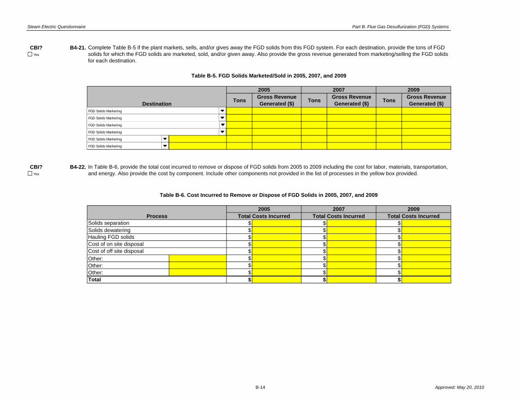
Steam Electric Questionnaire Part B. Flue Gas Desulfurization (FGD) Systems
CBI? B4-21.
TonsGross Revenue Generated ($)
TonsGross Revenue Generated ($)
TonsGross Revenue Generated ($)
CBI? B4-22.
$ $ $Solids dewatering $ $ $
$ $ $$ $ $$ $ $
Other: $ $ $Other: $ $ $Other: $ $ $
$ $ $Total
Cost of off site disposal
Complete Table B-5 if the plant markets, sells, and/or gives away the FGD solids from this FGD system. For each destination, provide the tons of FGD solids for which the FGD solids are marketed, sold, and/or given away. Also provide the gross revenue generated from marketing/selling the FGD solids for each destination.
Table B-5. FGD Solids Marketed/Sold in 2005, 2007, and 2009
Destination
2005 2007
Solids separation
Hauling FGD solidsCost of on site disposal
Process
In Table B-6, provide the total cost incurred to remove or dispose of FGD solids from 2005 to 2009 including the cost for labor, materials, transportation, and energy. Also provide the cost by component. Include other components not provided in the list of processes in the yellow box provided.
Table B-6. Cost Incurred to Remove or Dispose of FGD Solids in 2005, 2007, and 2009
Total Costs Incurred2005 2007 2009
Total Costs Incurred Total Costs Incurred
2009
Yes
Yes
FGD Solids Marketing
FGD Solids Marketing
FGD Solids Marketing
FGD Solids Marketing
FGD Solids Marketing
FGD Solids Marketing
B-14 Approved: May 20, 2010

Steam Electric Questionnaire Part B. Flue Gas Desulfurization (FGD) Systems
Plant ID:Plant Name:
Part: B
Section Title: 5. FGD Wastewater Generation
Instructions:
CBI? B5-1.
Percent80%20%
Other
Other
Other
Other
Other
Other
Other
CTBExample:
FGD Reagent Preparation Water, Absorber Make-Up Water, and Mist Eliminator Wash Water
(Sources, Percent Contribution, and Flow Rate)
Source(s)FGDB
FGD System ID
Insert Plant IDInsert Plant Name
Flow Rate(gpd)
48,00012,000
Table B-7. FGD System Water Sources and Flow Rates
In Table B-7, provide information for each wet FGD system that the plant operates reported in Table B-1. For the source of FGD reagent preparation water, absorber make-up water, and mist eliminator wash water, you may enter more than one source. Select a source from the dropdown menu. For the percent contribution of the flow rates, provide the percentage based on the total flow rate for all these sources entering the FGD system.
Throughout this section, you will be required to provide information for all wet FGD systems that the plant operates, reported in Table B-1. This section does not need to be completed for planned systems. Please provide all free response answers in the highlighted yellow areas.
FGD System Water Source
FGD System Water Source
FGD System Water SourceFGD System ID (no planned)
FGD System ID (no planned
FGD System Water Source
FGD System Water Source
FGD System Water SourceFGD System ID (no planned)
FGD System Water Source
FGD System Water Source
FGD System Water SourceFGD System ID (no planned)
FGD System Water Source
FGD System Water Source
FGD System Water SourceFGD System ID (no planned)
FGD System Water Source
FGD System Water Source
FGD System Water SourceFGD System ID (no planned)
FGD System Water Source
FGD System Water Source
FGD System Water SourceFGD System ID (no planned)
Yes
FGD System Water Source
FGD System Water Source
FGD System Water SourceFGD System ID (no planned)
FGD System Water Source
FGD System Water Source
FGD System Water SourceFGD System ID (no planned)
FGD System Water Source
FGD System Water Source
FGD System Water SourceFGD System ID (no planned)
FGD System Water Source
FGD System Water Source
FGD System Water SourceFGD System ID (no planned)
FGD System Water Source
FGD System Water Source
FGD System Water SourceFGD System ID (no planned)
B-15 Approved: May 20, 2010

Steam Electric Questionnaire Part B. Flue Gas Desulfurization (FGD) Systems
CBI? B5-2.
200 gpm 10 hpd240,000 12 to 16 120,000 gpd 365 dpy
gpm hpd
to gpd dpy
gpm hpd
to gpd dpy
gpm hpd
to gpd dpy
gpm hpd
to gpd dpy
gpm hpd
to gpd dpy
gpm hpd
to gpd dpy
CBI? B5-3.
ppm
ppm
Typical Range of Percent Solids of FGD Slurry Blowdown (or Slurry
Discharge) Exiting the Absorber
(%)
Typical Duration AND Frequency of
FGD Scrubber Purge (or Slurry Discharge)
Generation(hpd AND dpy)
Typical Amount of FGD Scrubber Purge (or
Slurry Discharge) Sent to Wastewater
Treatment or Discharge(gpm AND gpd)
Typical Amount of Solids
Separation Recycle
Returned to Absorber
(gpd)
180,000
Typical FGD Slurry Blowdown (or Slurry
Discharge) Flow Rate Exiting the Absorber
(gpd)FGD System IDExample:
Absorber Type
In Table B-8, provide information for each wet FGD system that the plant operates reported in Table B-1.
Table B-8. Water Generated from Wet FGD Systems
Provide the typical chlorides and solids concentrations of the untreated FGD scrubber purge (or slurry discharge ) transferred to the wastewater treatment system (after the FGD solids separation process, but prior to commingling with other process wastewater).
Yes
FGD-1 Recirculation
FGD System ID (no planned Recirculation/Single Pass
FGD System ID (no planned) Recirculation/Single Pass
FGD System ID (no planned) Recirculation/Single Pass
FGD System ID (no planned Recirculation/Single Pass
FGD System ID (no planned Recirculation/Single Pass
FGD System ID (no planned) Recirculation/Single Pass
Yes
Chlorides content:
Total suspended solids (TSS):
B-16 Approved: May 20, 2010

Steam Electric Questionnaire Part B. Flue Gas Desulfurization (FGD) Systems
Plant ID: Insert Plant IDPlant Name: Insert Plant Name
Part: BSection Title: 6. FGD Monitoring Data Instructions
Instructions:
CBI? B6-1.
(Provide the monitoring data as instructed below)
(Skip to Section 7)
Has your plant collected monitoring data (for any reason) for untreated FGD scrubber purge (or slurry discharge ) in the 12 months prior to receiving the ICR for any of the following analytes:
Note: The untreated FGD scrubber purge (or slurry discharge) stream is the FGD wastewater stream leaving the solids separation process prior to commingling with other water streams (see Figures B-1 and B-2).
Throughout this section, you will be required to provide monitoring data for all wet FGD systems that the plant operates, reported in Table B-1. This section does not need to be completed for planned systems. Please provide all free response answers in the highlighted yellow areas.
Metals (including monitoring data for total recoverable or dissolved metals analyses, or trace metals analyses);
Ammonia;
Nitrate/nitrite;
Total Kjeldahl nitrogen (TKN); and
Total cyanide.
Note: You are not required to perform non-routine tests or measurements solely for the purpose of responding to this question.
Provide the monitoring data in Table B-9 in the tab labeled "Part B Section 6 Table" for each different FGD scrubber purge stream for which the plant collected monitoring data. Report all results. Identify results that are less than the method detection limit (MDL), and results that are between the detection and reporting limits. For example, if the MDL is equal to 5 ng/L, the reporting limit is equal to 15 ng/L, and the value reported by the laboratory is 12 ng/L, report 12 ng/L as the measured value and identify and describe any qualifiers on the data in the corresponding column. Copy Table B-9 as many times as needed using the "Copy Table B-9" button below.
Yes
Yes
No
Copy Table B-9
B-17 Approved: May 20, 2010
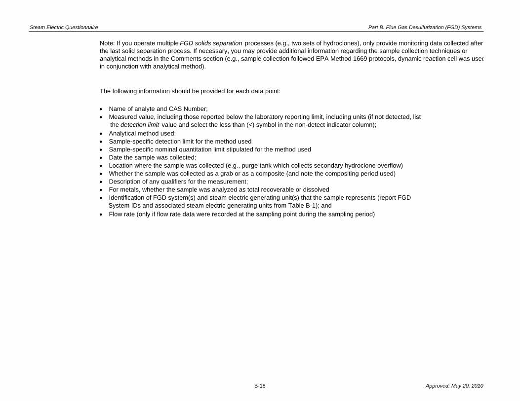
Steam Electric Questionnaire Part B. Flue Gas Desulfurization (FGD) Systems
The following information should be provided for each data point:
Name of analyte and CAS Number;
Analytical method used; Sample-specific detection limit for the method used; Sample-specific nominal quantitation limit stipulated for the method used; Date the sample was collected; Location where the sample was collected (e.g., purge tank which collects secondary hydroclone overflow) Whether the sample was collected as a grab or as a composite (and note the compositing period used) Description of any qualifiers for the measurement; For metals, whether the sample was analyzed as total recoverable or dissolved
Flow rate (only if flow rate data were recorded at the sampling point during the sampling period)
Identification of FGD system(s) and steam electric generating unit(s) that the sample represents (report FGD System IDs and associated steam electric generating units from Table B-1); and
Note: If you operate multiple FGD solids separation processes (e.g., two sets of hydroclones), only provide monitoring data collected after the last solid separation process. If necessary, you may provide additional information regarding the sample collection techniques or analytical methods in the Comments section (e.g., sample collection followed EPA Method 1669 protocols, dynamic reaction cell was usedin conjunction with analytical method).
Measured value, including those reported below the laboratory reporting limit, including units (if not detected, list the detection limit value and select the less than (<) symbol in the non-detect indicator column);
B-18 Approved: May 20, 2010

Steam Electric Questionnaire Part B. Flue Gas Desulfurization (FGD) Systems
Plant ID: Insert Plant IDPlant Name: Insert Plant Name
Part: BSection Title: 6. FGD Monitoring Data
Instructions:
CBI? B6-2.
Non- Detect
Indicator
Value Units Value Units Value Units
Analyzed as Total
Recoverable or Dissolved**
Flow Rate of FGD Scrubber
Purge (or Slurry Discharge) at
Time of Sampling (gpm)
Date Sample
CollectedLocation Collected
Collected as a Grab or
CompositeDescription of Qualifiers
Method Detection Limit Reporting Limit
Analyte
Complete Table B-9 for all monitoring data for untreated FGD scrubber purge (or slurry discharge) collected by the plant (for any reason) in the 12 months prior to receiving the ICR for any of the following analytes: metals (including monitoring data for total recoverable or dissolved metals analyses), ammonia, nitrate/nitrite, total Kjeldahl nitrogen (TKN), and total cyanide. Complete a separate table for each different FGD scrubber purge (or slurry discharge) stream for which the plant is providing monitoring data. Report all results. Identify results that are less than the method detection limit (MDL), and results that are between the detection and reporting limits. For Question B6-2, identify the FGD systems and steam electric generating units associated with the FGD scrubber purge data provided in the table. Refer to the instructions in Part B Section 6 if you need assistance completing Table B-9.
Throughout this section, you will be required to provide information on monitoring data for untreated FGD scrubber purge (or slurry discharge ) for all wet FGD systems that the plant operates, reported in Table B-1. This section does not need to be completed for planned systems. Please provide all free response answers in the highlighted yellow areas.
Table B-9. Monitoring Data for Untreated FGD Scrubber Purge (or Slurry Discharge)
CAS Number
Analytical method
Measured Value Including Units*
Identify the FGD systems and steam electric generating units associated with the FGD scrubber purge (or slurry discharge) monitoring data provided in the table below. Use the FGD system IDs identified in Table B-1 and the SE unit IDs identified in Table A-8. [Check all that apply.]
Yes
UnitsUnitsUnits Grab/Composite Total Recoverable/Dissolv
UnitsUnitsUnits Grab/Composite Total Recoverable/Dissolv
UnitsUnitsUnits Grab/Composite Total Recoverable/Dissolv
UnitsUnitsUnits Grab/Composite Total Recoverable/Dissolv
UnitsUnitsUnits Grab/Composite Total Recoverable/Dissolv
UnitsUnitsUnits Grab/Composite Total Recoverable/Dissolv
UnitsUnitsUnits Grab/Composite Total Recoverable/Dissolv
UnitsUnitsUnits Grab/Composite Total Recoverable/Dissolv
UnitsUnitsUnits Grab/Composite Total Recoverable/Dissolv
UnitsUnitsUnits Grab/Composite Total Recoverable/Dissolv
UnitsUnitsUnits Grab/Composite Total Recoverable/Dissolv
UnitsUnitsUnits Grab/Composite Total Recoverable/Dissolv
UnitsUnitsUnits Grab/Composite Total Recoverable/Dissolv
UnitsUnitsUnits Grab/Composite Total Recoverable/Dissolv
UnitsUnitsUnits Grab/Composite Total Recoverable/Dissolv
UnitsUnitsUnits Grab/Composite Total Recoverable/Dissolv
UnitsUnitsUnits Grab/Composite Total Recoverable/Dissolv
FGD-1
FGD-2
FGD-3
FGD-4
FGD-5
FGD-6
SE Unit-1
SE Unit-2
SE Unit-3
SE Unit-4
SE Unit-5
SE Unit-6
SE Unit-7
SE Unit-8
SE Unit-9
SE Unit-10
Non Detect Indic
Non Detect Indic
Non Detect Indic
Non Detect Indic
Non Detect Indic
Non Detect Indic
Non Detect Indic
Non Detect Indic
Non Detect Indic
Non Detect Indic
Non Detect Indic
Non Detect Indic
Non Detect Indic
Non Detect Indic
Non Detect Indic
Non Detect Indic
Non Detect Indic
B-19 Approved: May 20, 2010

Steam Electric Questionnaire Part B. Flue Gas Desulfurization (FGD) Systems
**Only answer for metals*If not detected, list the detection limit value and select the less than (<) symbol in the non-detect indicator column.
UnitsUnitsUnits Grab/Composite Total Recoverable/Dissolv
UnitsUnitsUnits Grab/Composite Total Recoverable/Dissolv
UnitsUnitsUnits Grab/Composite Total Recoverable/Dissolv
UnitsUnitsUnits Grab/Composite Total Recoverable/Dissolv
UnitsUnitsUnits Grab/Composite Total Recoverable/Dissolv
UnitsUnitsUnits Grab/Composite Total Recoverable/Dissolv
UnitsUnitsUnits Grab/Composite Total Recoverable/Dissolv
UnitsUnitsUnits Grab/Composite Total Recoverable/Dissolv
UnitsUnitsUnits Grab/Composite Total Recoverable/Dissolv
UnitsUnitsUnits Grab/Composite Total Recoverable/Dissolv
UnitsUnitsUnits Grab/Composite Total Recoverable/Dissolv
UnitsUnitsUnits Grab/Composite Total Recoverable/Dissolv
UnitsUnitsUnits Grab/Composite Total Recoverable/Dissolv
UnitsUnitsUnits Grab/Composite Total Recoverable/Dissolv
UnitsUnitsUnits Grab/Composite Total Recoverable/Dissolv
UnitsUnitsUnits Grab/Composite Total Recoverable/Dissolv
UnitsUnitsUnits Grab/Composite Total Recoverable/Dissolv
UnitsUnitsUnits Grab/Composite Total Recoverable/Dissolv
UnitsUnitsUnits Grab/Composite Total Recoverable/Dissolv
UnitsUnitsUnits Grab/Composite Total Recoverable/Dissolv
UnitsUnitsUnits Grab/Composite Total Recoverable/Dissolv
UnitsUnitsUnits Grab/Composite Total Recoverable/Dissolv
UnitsUnitsUnits Grab/Composite Total Recoverable/Dissolv
UnitsUnitsUnits Grab/Composite Total Recoverable/Dissolv
Non Detect Indic
Non Detect Indic
Non Detect Indic
Non Detect Indic
Non Detect Indic
Non Detect Indic
Non Detect Indic
Non Detect Indic
Non Detect Indic
Non Detect Indic
Non Detect Indic
Non Detect Indic
Non Detect Indic
Non Detect Indic
Non Detect Indic
Non Detect Indic
Non Detect Indic
Non Detect Indic
Non Detect Indic
Non Detect Indic
Non Detect Indic
Non Detect Indic
Non Detect Indic
Non Detect Indic
B-20 Approved: May 20, 2010

Steam Electric Questionnaire Part B. Flue Gas Desulfurization (FGD) Systems
Plant ID:Plant Name:
Part: BSection Title: 7. FGD Wastewater Treatment
Instructions:
CBI? B7-1.
(Continue)
(Skip to Question B7-4)
CBI? B7-2.
CBI? B7-3.
Insert Plant IDInsert Plant Name
Does the plant transfer the FGD scrubber purge (or slurry discharge ) to a settling pond ?
Throughout this section, you will be required to provide information for all wet FGD systems that the plant operates, reported in Table B-1. This section does not need to be completed for planned systems. Please provide all free response answers in the highlighted yellow areas.
Indicate which process wastewaters are commingled with the FGD scrubber purge (or slurry discharge) in the settling pond. [Check all boxes that apply.]
If the FGD scrubber purge (or slurry discharge) is commingled with bottom ash or fly ash sluice water in the pond(s), select the option below that best describes the configuration of the pond(s). If neither option applies, provide an explanation in the space provided:
Yes
Yes
No
Fly ash sluice
Metal cleaning waste
Mill reject sluice
None
Bottom ash sluice
Boiler blowdown
Other, explain:
Other, explain:
“True” commingling: FGD scrubber purge (or slurry discharge) and bottom ash and/or fly ash sluice water are combined in one pond dedicated to the treatment of both waters
FGD scrubber purge (or slurry discharge) is treated in a FGD pond and subsequently commingled with ash water in a dedicated ash pond
FGD scrubber purge (or slurry discharge) is not commingled with other wastewaters
Other, explain:
FGD scrubber purge (or slurry discharge) wastewater is treated using a wastewater treatment system other than a settling pond and subsequently commingled with ash water in a dedicated ash pond
Yes
Yes
B-21 Approved: May 20, 2010

Steam Electric Questionnaire Part B. Flue Gas Desulfurization (FGD) Systems
CBI? B7-4.
CBI? B7-5.
CBI? B7-6.
(Continue)
(Skip to Section 8)
gpd dpy
Indicate all intermediate and final destination(s) of the treated FGD scrubber purge (or slurry discharge). If the plant recycles the treated FGD scrubber purge (or slurry discharge), indicate the plant process to which this water is recycled. [Check all that apply].
Plants that produce gypsum from wet FGD systems may generate water from the storage and handling of gypsum. Examples of gypsum-related waters are gypsum wash water and gypsum pile runoff . Are gypsum-related waters generated at the plant? Note: gypsum-related water does not include FGD slurry blowdown or FGD scrubber purge (or slurry discharge).
If yes, provide the typical volume of gypsum-related waters generated per day (gpd) and the frequency of water generation (dpy) for calendar year 2009.
Indicate wastewater treatment technologies used to treat the FGD scrubber purge (or slurry discharge). [Check all boxes that apply.]
Settling pond
Biological reactor – aerobic
Mechanical vapor compression (brine concentrator)
Mechanical vapor compression (brine concentrator) with spray dryer
Chemical precipitation
Biological reactor – anoxic/anaerobic
Mechanical vapor compression (brine concentrator) with crystallizer
Other, explain:
Constructed wetlands
Yes
No
Yes
Yes
Yes
Indirect discharge to a publicly or privately owned treatment works
Other, explain:
Immediately recycled back to plant process. Please describe how the treated FGD scrubber purge (or slurry discharge) is reused:
Discharged to surface water. Provide NPDES permitted outfall number (from Part A Section 2.2):
Deep well injection
B-22 Approved: May 20, 2010

Steam Electric Questionnaire Part B. Flue Gas Desulfurization (FGD) Systems
CBI? B7-7. Indicate how the gypsum-related waters are handled. [Check all boxes that apply.]
Reused in FGD process
Reused in other process operations. Please describe how the gypsum-related waters are reused:
Transferred to treatment system reported in Tables D-1 or D-2. Identify the type of treatment system below. [Check all that apply.]
Discharged to surface water. Provide NPDES permitted outfall number (from Part A Section 2.2):
Indirect discharge to a publicly or privately owned treatment works
Other, explain:
Yes
Settling pond
Biological reactor – aerobic
Mechanical vapor compression (brine concentrator)
Mechanical vapor compression (brine concentrator) with spray dryer
Chemical precipitation
Biological reactor – anoxic/anaerobic
Mechanical vapor compression (brine concentrator) with crystallizer
Other, explain:
Constructed wetlands
B-23 Approved: May 20, 2010

Steam Electric Questionnaire Part B. Flue Gas Desulfurization (FGD) Systems
Plant ID: Insert Plant IDPlant Name: Insert Plant Name
FGD System ID: Insert System ID
Part: BSection Title: 8. Dry FGD System Information
Instructions:
CBI? B8-1.
(Continue)
(Skip to next Questionnaire Part)
CBI? B8-2.
Throughout this section, you will be required to provide information for each dry FGD system that the plant operates, reported in Table B-1. This section does not need to be completed for planned systems. Please provide all free response answers in the highlighted yellow areas.
Make copies of Section 8 and Section 8 tables for each dry FGD system previously defined in Table B-1 using the Copy Section 8 and Section 8 Tables button below. Please note that you will create two new tabs for these sections. You may delete unneeded tabs, if accidently created. Enter the FGD system ID in the space provided above (use FGD system IDs assigned in Table B-1).
Did you report use of a dry FGD system in Table B-1?
Indicate how the FGD solid is removed from the flue gas. Yes
Fabric filter
Other, specify
ESP
Yes
Yes
No
Copy Section 8 and Section 8 Tables
B-24 Approved: May 20, 2010

Steam Electric Questionnaire Part B. Flue Gas Desulfurization (FGD) Systems
CBI? B8-3.
CBI? B8-4.
ppm
%
CBI? B8-5.
gpm
hpd
dpy
CBI? B8-6.
CBI? B8-7.
(Continue)
Provide the flow rate, duration, and frequency of the FGD reagent preparation water for the FGD system for calendar year 2009.
Provide the source of the FGD reagent preparation water used. [Check all boxes that apply.]
Is any FGD wastewater generated from the operation of the dry FGD scrubber?
For water sources that may be used as a source of FGD reagent preparation water (e.g., fresh intake, recycled process water), indicate the maximum chlorides concentration and maximum solids percentage that is acceptable for the water to be used for those purposes. Identify any other criteria that the source water must meet.
Is the FGD system located upstream or downstream of the fly ash collection system?
(Skip to Question B8-9)
Chlorides concentration:
Solids percentage:
Other, explain:
Raw intake water
Intake water that has been treated on site prior to use
Process wastewater, specify
Other, explain:
Yes
No
Upstream of fly ash collection
Downstream of fly ash collection
Yes
Yes
Yes
Yes
Yes
Process Wastewater
B-25 Approved: May 20, 2010

Steam Electric Questionnaire Part B. Flue Gas Desulfurization (FGD) Systems
CBI? B8-8.
CBI? B8-9.
(Continue)
Provide the volume and frequency of wastewater generated from the dry FGD scrubber in 2009.
gpd over days
Indicate all intermediate and final destination(s) of the FGD wastewater. If the plant recycles the FGD wastewater, indicate the plant process to which this water is recycled. [Check all that apply].
(Skip to Question B8-11)
Is any FGD wastewater generated from cleaning the dry FGD scrubber (e.g., power washing during scheduled generating unit outages)?
Yes
No
Yes
Indirect discharge to a publicly or privately owned treatment works
Immediately recycled back to plant process. Please describe how the FGD wastewater is reused:
Discharged to surface water. Provide NPDES permitted outfall number (from Part A Section 2.2):
Deep well injection
Other, explain:
Transferred to treatment system reported in Tables D-1 or D-2. Identify the type of treatment system below. [Check all boxes that apply.]
Settling pond
Biological reactor – aerobic
Mechanical vapor compression (brine concentrator)
Mechanical vapor compression (brine concentrator) with spray dryer
Chemical precipitation
Biological reactor – anoxic/anaerobic
Mechanical vapor compression (brine concentrator) with crystallizer
Other, explain:
Constructed wetlands
Yes
B-26 Approved: May 20, 2010

Steam Electric Questionnaire Part B. Flue Gas Desulfurization (FGD) Systems
CBI? B8-10.
CBI? B8-11.
ppm
ppm
ppm
What parameters affect the ability of the FGD solids to be marketed, sold and/or given away? [Check all boxes that apply.]
Indicate all intermediate and final destination(s) of the FGD wastewater from cleaning. If the plant recycles the FGD wastewater from cleaning, indicate the plant process to which this water is recycled. [Check all that apply].
Yes
Chlorides content:
Moisture content:
Other, specify:
None – Industry(ies) to which the FGD solids are marketed has not specified standards for the solids.
N/A – FGD solids are not marketed, sold, or given away.
Indirect discharge to a publicly or privately owned treatment works
Immediately recycled back to plant process. Please describe how the FGD wastewater is reused:
Discharged to surface water. Provide NPDES permitted outfall number (from Part A Section 2.2):
Deep well injection
Other, explain:
Transferred to treatment system reported in Tables D-1 or D-2. Identify the type of treatment system below. [Check all boxes that apply.]
Settling pond
Biological reactor – aerobic
Mechanical vapor compression (brine concentrator)
Mechanical vapor compression (brine concentrator) with spray dryer
Chemical precipitation
Biological reactor – anoxic/anaerobic
Mechanical vapor compression (brine concentrator) with crystallizer
Other, explain:
Constructed wetlands
Yes
B-27 Approved: May 20, 2010

Steam Electric Questionnaire Part B. Flue Gas Desulfurization (FGD) Systems
Plant ID: Insert Plant IDPlant Name: Insert Plant Name
FGD System ID: Insert System ID
Part: BSection Title: 8. FGD Solids Disposition and Marketing for Dry FGD Systems
Instructions:
CBI? B8-12.
Stored permanently
Stored temporarily (later hauled off-site/marketed)
Stored permanently
Stored temporarily (later hauled off-site/marketed)
Other, explain:
Other, explain:
Ultimate Destination of FGD Solids
Sent to Landfills reported in Table A-6
Amount Disposed in 2009 (tons)
Marketed and sold
Sent to Pond/Impoundment reported in Table A-4
Sent to Pond/Impoundment not reported in Table A-4
Sent to Landfills not reported in Table A-6
Amount Disposed in 2005 (tons)
Amount Disposed in 2007 (tons)
In Table B-10, indicate the ultimate destination of FGD solids from the FGD system and provide the tonnage for each type of storage/handling technique for calendar years 2005, 2007, and 2009. If the FGD solids are stored in a landfill or pond/impoundment , provide the amount of FGD solids stored permanently and/or temporarily.
For example, a plant may operate a gypsum landfill, and some amount of FGD solids that are transferred to the landfill may later be removed from the landfill and sold for use in wallboard manufacturing. In this case, the amount of FGD solids sold for wallboard manufacturing should be identified in BOTH the "Landfills reported in Table A-6: Stored temporarily" category AND the "Marketed and Sold" category. In this same example, all the FGD solids that are transferred to the landfill and left in the landfill should be identified as "Landfills reported in Table A-6: Stored permanently."
Given away
Throughout this section, you will be required to provide information on FGD solids disposition for all dry FGD systems that the plant operates reported in Table B-1. This section does not need to be completed for planned systems. Please provide all free response answers in the highlighted yellow areas.
Table B-10. FGD Solids Disposition for 2005, 2007, and 2009
YesYes
B-28 Approved: May 20, 2010
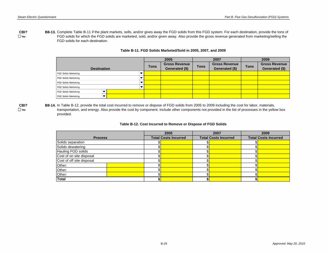
Steam Electric Questionnaire Part B. Flue Gas Desulfurization (FGD) Systems
CBI? B8-13.
TonsGross Revenue Generated ($)
TonsGross Revenue Generated ($)
TonsGross Revenue Generated ($)
CBI? B8-14.
$ $ $Solids dewatering $ $ $
$ $ $$ $ $$ $ $
Other: $ $ $Other: $ $ $Other: $ $ $
$ $ $
Complete Table B-11 if the plant markets, sells, and/or gives away the FGD solids from this FGD system. For each destination, provide the tons of FGD solids for which the FGD solids are marketed, sold, and/or given away. Also provide the gross revenue generated from marketing/selling the FGD solids for each destination.
Table B-11. FGD Solids Marketed/Sold in 2005, 2007, and 2009
Destination
2005 2007 2009
In Table B-12, provide the total cost incurred to remove or dispose of FGD solids from 2005 to 2009 including the cost for labor, materials, transportation, and energy. Also provide the cost by component. Include other components not provided in the list of processes in the yellow box provided.
Table B-12. Cost Incurred to Remove or Dispose of FGD Solids
2007 2009Total Costs Incurred Total Costs Incurred Total Costs Incurred
Total
Solids separation
Hauling FGD solidsCost of on site disposal Cost of off site disposal
Process2005
Yes
Yes
Yes
Yes
FGD Solids Marketing
FGD Solids Marketing
FGD Solids Marketing
FGD Solids Marketing
FGD Solids Marketing
FGD Solids Marketing
B-29 Approved: May 20, 2010

Steam Electric Questionnaire Part B. Flue Gas Desulfurization (FGD) Systems
Plant Name: Insert Plant IDPlant ID: Insert Plant Name
Part: BSection Title: Part B Comments
Instructions:
Question Number
CBI?
CBI?
CBI?
CBI?
CBI?
CBI?
CBI?
CBI?
CBI?
Cross reference your comments by question number and indicate the confidential status of your comment by checking the box next to “Yes” under "CBI?" (Confidential Business Information).
Comment
Yes
Yes
Yes
Yes
Yes
Yes
Yes
Yes
Yes
B-30 Approved: May 20, 2010

Steam Electric Questionnaire Part B. Flue Gas Desulfurization (FGD) Systems
CBI?
CBI?
CBI?
CBI?
CBI?
CBI?
CBI?
CBI?
CBI?
CBI?
CBI?
CBI?
CBI?
CBI?
Yes
Yes
Yes
Yes
Yes
Yes
Yes
Yes
Yes
Yes
Yes
Yes
Yes
Yes
B-31 Approved: May 20, 2010

Steam Electric Questionnaire Part B. Flue Gas Desulfurization (FGD) Systems
Air heater cleaning water AHCWAsh pile runoff APR Effluent - 1 EFF-1Boiler blowdown BB Effluent - 2 EFF-2Boiler fireside cleaning water BFCW Effluent - 3 EFF-3Boiler tube cleaning water BTCW Effluent - 4 EFF-4Bottom ash sluice BAS Effluent - 5 EFF-5Carbon capture wastewater CCAPW Effluent - 6 EFF-6Coal pile runoff CPR Filter backwash FltBWCombined ash sluice CAS Sludge SLDGCombustion turbine cleaning (combustion gas portion of turbine) water
COMBCW
Combustion turbine cleaning (compressor portion of the turbine) water
COMPRCW POND-1 Effluent POND-1-EFF
Combustion turbine evaporative coolers blowdown TECB POND-2 Effluent POND-2-EFFCooling tower blowdown CTB POND-3 Effluent POND-3-EFFFGD scrubber purge SCRBP POND-4 Effluent POND-4-EFFFGD slurry blowdown FGDB POND-5 Effluent POND-5-EFFFilter Backwash FLTBW POND-6 Effluent POND-6-EFFFloor drain wastewater FDW POND-7 Effluent POND-7-EFFFlue gas mercury control system wastewater FGMCW POND-8 Effluent POND-8-EFFFly ash sluice FAS POND-9 Effluent POND-9-EFFGeneral runoff GR POND-10 Effluent POND-10-EFFGypsum pile runoff GPR POND-A Effluent POND-A-EFFGypsum wash water GYPWW POND-B Effluent POND-B-EFFIon exchange wastewater IXW POND-C Effluent POND-C-EFFLandfill runoff - capped landfill LRC WWT-1 Effluent WWT-1-EFFLandfill runoff - uncapped landfill LRUC WWT-2 Effluent WWT-2-EFFLeachate LEACH WWT-3 Effluent WWT-3-EFFLimestone pile runoff LPR WWT-4 Effluent WWT-4-EFFMill reject sluice MRS WWT-5 Effluent WWT-5-EFF
For Use as Influents to Pond/Impoundment Systems and/or Wastewater Treatment Systems in Part D, Table D-3, AND
Recycled Waters Throughout Questionnaire.
Steam Electric Questionnaire Code Tables
For Use as Effluents from Pond/Impoundment Systems and/or Wastewater Treatment Systems in Part D, Table D-4.
Process Wastewaters Treated Wastewaters
For Use in Tables and Questions throughout Parts A, B, C, D, and F.
Approved: May 20, 2010

Steam Electric Questionnaire Part B. Flue Gas Desulfurization (FGD) Systems
Steam Electric Questionnaire Code Tables
Once -through cooling water CW WWT-6 Effluent WWT-6-EFFReverse osmosis reject water RORW WWT-A Effluent WWT-A-EFFSCR catalyst regeneration wastewater SCRRW WWT-B Effluent WWT-B-EFFSCR catalyst washing wastewater SCRWW WWT-C Effluent WWT-C-EFFSoot blowing wash water SOOTWSteam turbine cleaning water STCWYard drain wastewater YARDW
For Use in Tables and Questions throughout Parts A, B, C, D, and F.For Use as Influents to Pond/Impoundment Systems and/or Wastewater Treatment Systems in Part D, Table D-3, AND
Recycled Waters Throughout Questionnaire.
Treated WastewatersProcess Wastewaters
Approved: May 20, 2010

Steam Electric Questionnaire Part B. Flue Gas Desulfurization (FGD) Systems
Steam Electric Questionnaire Code Tables
Adsorptive media ADSORB Burned on site BURNAerobic Biological Reactor AERBIO Deep-well injection DWELL
Anaerobic Biological Reactor ANBIO Discharge to POTW POTWAerobic/Anaerobic Biological Reactor AER/ANBIO Discharge to PrOTW PrOTWChemical Precipitation Reaction Tank 1 - 1 CP-1-1 Discharge to surface water SWChemical Precipitation Reaction Tank 1 - 2 CP-1-2 Evaporation EVAPChemical Precipitation Reaction Tank 2 - 1 CP-2-1 Hauled off site for reuse
(removal fee)HAULR - RF
Chemical Precipitation Reaction Tank 2 - 2 CP-2-2 Hauled off site for reuse (given away)
HAULR - GA
Chemical Precipitation Reaction Tank 3 - 1 CP-3-1 Hauled off site for reuse (marketed and sold)
SOLD
Chemical Precipitation Reaction Tank 3 - 2 CP-3-2 Hauled off site for disposal HAULClarification, Primary - 1 CL-P-1 Mixed with fly ash for disposal MFA
Clarification, Primary - 2 CL-P-2 On-site landfill (as reported in Table A-6)
LANDF
Clarification, Secondary - 1 CL-S-1 POND-1 POND-1Clarification, Secondary - 2 CL-S-2 POND-2 POND-2Clarification, Tertiary - 1 CL-T-1 POND-3 POND-3Clarification, Tertiary - 2 CL-T-2 POND-4 POND-4Constructed wetland - Cell 1 CWL -1 POND-5 POND-5Constructed wetland - Cell 2 CWL -2 POND-6 POND-6Constructed wetland - Cell 3 CWL -3 POND-7 POND-7Constructed wetland - Cell 4 CWL -4 POND-8 POND-8Constructed wetland - Cell 5 CWL -5 POND-9 POND-9Constructed wetland - Cell 6 CWL -6 POND-10 POND-10Constructed wetland system CWTS POND-A POND-AEqualization, Primary EQ-P POND-B POND-BEqualization, Secondary EQ-S POND-C POND-CFilter, Microfiltration - 1 FLT-M-1 WWT-1 WWT-1Filter, Microfiltration - 2 FLT-M-2 WWT-2 WWT-2
For Use in Tables and Questions Throughout Parts D and F.
Wastewater Treatment Units DestinationsFor Use in Tables and Questions Throughout Parts A, C, D,
and F.
Approved: May 20, 2010

Steam Electric Questionnaire Part B. Flue Gas Desulfurization (FGD) Systems
Steam Electric Questionnaire Code Tables
Filter, Microfiltration - 3 FLT-M-3 WWT-3 WWT-3
Filter, Microfiltration - 4 FLT-M-4 WWT-4 WWT-4Filter, Sand/Gravity - 1 FLT-S-1 WWT-5 WWT-5Filter, Sand/Gravity - 2 FLT-S-2 WWT-6 WWT-6Filter, Sand/Gravity - 3 FLT-S-3 WWT-A WWT-AFilter, Sand/Gravity - 4 FLT-S-4 WWT-B WWT-BFilter, Ultrafiltration - 1 FLT-U-1 WWT-C WWT-CFilter, Ultrafiltration - 2 FLT-U-2 Reuse as boiler water RECYC - BWFilter, Ultrafiltration - 3 FLT-U-3 Reuse as bottom ash sluice RECYC - BASFilter, Ultrafiltration - 4 FLT-U-4 Reuse as combined ash sluice RECYC - CAS
Filter press - 1 FP-1 Reuse as FGD slurry preparation water
RECYC - FGDP
Filter press - 2 FP-2 Reuse as FGD absorber makeup
RECYC - FGDAB
Holding tank HT Reuse as fly ash sluice RECYC - FASIon exchange IX Reuse as mill reject sluice RECYC - MRSNatural wetlands NW Reuse in cooling towers RECYC - CWpH adjustment - 1 PH-1pH adjustment - 2 PH-2pH adjustment - 3 PH-3Reverse osmosis ROSPond Unit - 1 SPD-1Pond Unit - 2 SPD-2Pond Unit - 3 SPD-3Pond Unit - 4 SPD-4Pond Unit - 5 SPD-5Pond Unit - 6 SPD-6Pond Unit - 7 SPD-7Pond Unit - 8 SPD-8Pond Unit - 9 SPD-9
For Use in Tables and Questions Throughout Parts D and F.For Use in Tables and Questions Throughout Parts A, C, D,
and F.
DestinationsWastewater Treatment Units
Approved: May 20, 2010

Steam Electric Questionnaire Part B. Flue Gas Desulfurization (FGD) Systems
Steam Electric Questionnaire Code Tables
Pond Unit - 10 SPD-10Centrifuge - 1 CENT-1
Pond Unit - 11 SPD-11 Centrifuge - 2 CENT-2Pond Unit - 12 SPD-12 Centrifuge - 3 CENT-3Pond Unit - 13 SPD-13 Centrifuge - 4 CENT-4Pond Unit - 14 SPD-14 Hydrocyclones - 1 HYC-1Settling tank - 1 ST-1 Hydrocyclones - 2 HYC-2Settling tank - 2 ST-2 Hydrocyclones - 3 HYC-3Settling tank - 3 ST-3 Hydrocyclones - 4 HYC-4Settling tank - 4 ST-4 Filter press - 1 FP-1Settling tank - 5 ST-5 Filter press - 2 FP-2Thickener - 1 TH-1 Thickener - 1 TH-1Thickener - 2 TH-2 Thickener - 2 TH-2Vacuum drum filter - 1 VF-1 Vacuum drum filter - 1 VF-1Vacuum drum filter - 2 VF-2 Vacuum drum filter - 2 VF-2Vacuum filter belt - 1 VFB-1 Vacuum filter belt - 1 VFB-1Vacuum filter belt - 2 VFB-2 Vacuum filter belt - 2 VFB-2
Solids HandlingWastewater Treatment Units
For Use in Tables and Questions Throughout Parts D and F. For Use as Planned Solids Handling for the FGD Slurry Blowdown in Part B Table B-2.
Approved: May 20, 2010

Steam Electric Questionnaire Part B. Flue Gas Desulfurization (FGD) Systems
Yes/No Recirculation/Single Pass FGD System ID FGD System Water Source Process Wastewater FGD Solids Marketing
Select Select Select Select Select Select
No Recirculation FGD-1 Air heater cleaning water Air heater cleaning water Agriculture
Yes Single Pass FGD-2 Ash pile runoff Ash pile runoff Blended cement/raw feed for clinker
FGD-3 Boiler blowdown Boiler blowdown Concrete/concrete products
Steam Electric Generating Units FGD-4 Boiler fireside cleaning water Boiler fireside cleaning water Flowable fill
Materials of Construction Select FGD-5 Boiler tube cleaning water Boiler tube cleaning water Gypsum panel products (not wallboard)
Select SEUnit-1 FGD-6 Bottom ash sluice Bottom ash sluice Mining applications
2205 stainless steel SEUnit-2 FGD-A Carbon capture wastewater Carbon capture wastewater Soil modification/stabilization
255 stainless steel SEUnit-3 FGD-B Coal pile runoff Coal pile runoff Structural fills/embankments
316L stainless steel SEUnit-4 FGD-C Combined ash sluice Combined ash sluice Wallboard manufacturing
317LM stainless steel
SEUnit-5
Combustion turbine cleaning
(combustion gas portion of
turbine) water
Combustion turbine cleaning
(combustion gas portion of
turbine) water Waste stabilization/solidification
317LMN stainless steel
SEUnit-6 FGD System ID (no planned)
Combustion turbine cleaning
(compressor portion of the
turbine) water
Combustion turbine cleaning
(compressor portion of the
turbine) water Other (specify):
625 stainless steel
SEUnit-7 Select
Combustion turbine evaporative
coolers blowdown
Combustion turbine evaporative
coolers blowdown
Carbon Steel SEUnit-8 FGD-1 Cooling tower blowdown Cooling tower blowdown Total Recoverable/Dissolved
Ceramic SEUnit-9 FGD-2
FGD scrubber purge (or slurry
discharge)
FGD scrubber purge (or slurry
discharge) Select
Duplex Stainless Steel SEUnit-10 FGD-3 FGD slurry blowdown FGD slurry blowdown Dissolved
Fiberglass FGD-4 Filter Backwash Filter Backwash Total Recoverable
Masonry Tile Lined Carbon Steel Type of FGD System FGD-5 Floor drain wastewater Floor drain wastewater N/A
Masonry Tile Lined Concrete Select FGD-6
Flue gas mercury control system
wastewater
Flue gas mercury control system
wastewater
Mild Stainless Steel Circulating dry scrubber Fly ash sluice Fly ash sluice Units
Nickel Alloy Steel Jet bubbling reactor General runoff General runoff Select
Nickel Alloy Steel Lined Carbon Steel Mechanically aided Type of Sorbent Gypsum pile runoff Gypsum pile runoff mg/L
Plastic Packed Select Gypsum wash water Gypsum wash water ug/L
Plastic Lined Carbon Steel Spray Lime Ion exchange wastewater Ion exchange wastewater ng/L
Rubber Lined Carbon Steel Spray/Tray Limestone Landfill runoff - capped landfill Landfill runoff - capped landfill
Rubber Lined Concrete Spray Dryer Magnesium Lime
Landfill runoff - uncapped landfill Landfill runoff - uncapped landfill
Super Austenitic Stainless Steel Tray Magnesium Oxide Leachate Leachate Non Detect Indicators
Other (specify to the right) Venturi Soda Ash Limestone pile runoff Limestone pile runoff Select
Other (specify below) Sodium Hydroxide Mill reject sluice Mill reject sluice <
Grab/Composite Other (specify) Once -through cooling water Once -through cooling water
Select New/Existing Not Applicable Raw intake water Reverse osmosis reject water
Composite Select Raw intake water as makeup
SCR catalyst regeneration
wastewater
Grab Existing FGD System ID (Planned)
Reverse osmosis reject water SCR catalyst washing
wastewater
New Select
SCR catalyst regeneration
wastewater
Soot blowing wash water
FGD-A
SCR catalyst washing
wastewater
Steam turbine cleaning water
FGD-B Soot blowing wash water Yard drain wastewater
FGD-C Steam turbine cleaning water Other (specify to the right)
Treated intake water
Treated intake water as makeup
Yard drain wastewater
Approved: May 20, 2010

OMB Control Number: 2040-0281 Plant ID: Insert Plant ID
Approval Expires: 05/31/2013 Plant Name: Insert Plant Name
Section Title Tab Name
Part C Instructions Part C Instructions
Ash Generation Part C Section 1
Fly Ash Handling - Generating Unit Level Information Part C Section 2.1
Fly Ash Handling - Storage and Use Data Part C Section 2.2
Fly Ash Cost Information - Conveyance Part C Section 2.3
Fly Ash Cost Information - Intermediate Storage Part C Section 2.4
Fly Ash Cost Information - Transport/Disposal Part C Section 2.5
Bottom Ash Handling - Generating Unit Level Information Part C Section 3.1
Bottom Ash Handling - Storage and Use Data Part C Section 3.2
Bottom Ash Cost Information - Conveyance Part C Section 3.3
Bottom Ash Cost Information - Intermediate Storage Part C Section 3.4
Bottom Ash Cost Information - Transport/Disposal Part C Section 3.5
Economizer Ash Handling Information Part C Section 4
Air Heater Ash Handling Information Part C Section 5
Part C Comments Part C Comments
Steam Electric Questionnaire Code Tables Code Tables
Steam Electric Questionnaire
PART C - ASH HANDLING
Table of Contents
Approved: May 20, 2010

Steam Electric Questionnaire Part C. Instructions
Plant ID: Insert Plant ID
Plant Name: Insert Plant Name
Refer to the following definitions throughout Part C:
PART C. ASH HANDLING
Use the Part C Comments tab to do the following: provide additional information as
requested in certain questions within Part C; indicate atypical data (e.g., if 2009
information is not representative of normal operations); and note methods used to make
best engineering estimates in the event that exact data are not available.
INSTRUCTIONS
Part C requests information about ash handling operations at your plant. Complete Part
C if ash is generated in any fossil-fueled steam electric generating units at your plant.
See Part A Section 8 for steam electric generating unit fuel classifications.
As you are completing the electronic form, note the following: When you enter your plant
name and plant ID on the Part C TOC tab, all name and ID fields throughout Part C will
automatically populate. Refer to the overall questionnaire instructions, the glossary, and
the acronym list for assistance with completing Part C.
Please provide all free response answers in the highlighted yellow areas. Throughout
Part C, you may need to make copies of certain sections/questions. Instructions are
provided throughout Part C regarding making copies. Note that Steam Electric Unit IDs
or Storage IDs must be populated on the copied tab or section, located in the upper right
corner under "Plant ID" and "Plant Name", in order to correlate the requested
information with the steam electric unit or ash handling system.
Where the questionnaire indicates to provide an attachment, an electronic format (e.g.,
PDF) is preferred; however, hardcopies are also acceptable.
Approved: May 20, 2010

Steam Electric Questionnaire Part C. Instructions
"Fly ash collection" is the separation of fly ash from the flue gas. Examples of fly ash
collection equipment include ESPs and baghouses. Fly ash may also be collected by
wet scrubbers.
"Fly ash conveyance" is the conveyance of fly ash from the fly ash collection
equipment (ESP or baghouse) of one or more generating units to intermediate or final
storage (e.g., storage silos or ponds/impoundments). Common dry fly ash conveyance
components include filter/separators, vacuum/pressure transfer stations, high pressure
blowers, and associated high pressure piping (note that conveyance does NOT include
the storage/loading silos). Wet fly ash conveyance equipment is used to sluice fly ash
and pump it to wet ash storage (e.g., ash ponds/impoundments).
"Bottom ash conveyance" is the conveyance of bottom ash from the boiler(s) of one
or more generating units to the intermediate or final storage of the bottom ash. Dry
bottom ash conveyance does not use water to convey bottom ash to intermediate/final
storage. Dry bottom ash conveyance includes systems that collect and convey the
bottom ash without any use of water, as well as systems in which bottom ash is
conveyed mechanically or pneumatically away from a quench water bath (e.g.,
submerged chain conveyor systems). Wet bottom ash conveyance uses water (i.e., a
sluice) to convey bottom ash away from the boiler to intermediate/final storage (e.g.,
ponds/impoundments). Note that dewatering bins are considered part of bottom ash
conveyance.
"Intermediate storage" refers to a facility or site where collected fly ash or bottom ash
is stored after conveyance and prior to being transported to final disposal. Dry fly ash
intermediate storage typically consists of storage silos. Dry bottom ash intermediate
storage typically consists of stackout piles for the bottom ash collected from mechanical
drag systems. Wet fly ash or bottom ash intermediate storage typically consists of
ponds/impoundments.
"Ash transport/disposal" refers to the transportation of ash from intermediate storage
to final disposal. Examples of ash transport/disposal include transportation used to haul
ash off site (e.g., ash that is marketed and shipped off site to a reuse application). Ash
transport typically consists of roads and vehicles that are used to transport the ash.
Approved: May 20, 2010

Steam Electric Questionnaire Part C. Ash Handling
Plant ID: Insert Plant ID
Plant Name: Insert Plant Name
Part: C
Section Title: 1. Ash Generation
CBI? C1-1.
(Continue)
(Skip to next Questionnaire Part)
CBI? C1-2.
Acreage
Specify type(s):
Other:
Other:
CBI? C1-3.
(Continue)
(Skip to Section 3.1)
Is ash generated in any fossil-fueled steam electric generating units at the plant? See Part A Section 8 for steam electric
generating unit fuel classifications.
Active/Inactive/Open ash ponds
Category
Total Plant Area
Parking lots
Buildings and Other Developed Areas
Is fly ash generated in any fossil-fueled steam electric generating units at the plant? See Part A Section 8 for steam electric
generating unit fuel classifications.
Unusable land (e.g., wetlands, cooling reservoir)
Table C-1. Plant Acreage Breakdown
In Table C-1, indicate the total acreage of the plant for each of the following categories, including all contiguous and non-adjoining
property within 20 miles under the operational control of the plant or operated by the same ultimate parent, and receiving the
plant's waste.
Active/Inactive/Open landfills
Closed ponds/impoundments and landfills
YesYes
YesYes
Yes
No
YesYes
Yes
No
C-1 Approved: May 20, 2010

Steam Electric Questionnaire Part C. Ash Handling
Plant ID:
Plant Name:
SE Unit ID:
Part: C
Section Title: 2.1. Fly Ash Handling - Generating Unit Level Information
Instructions:
CBI? C2-1.
●
●
●
1,500 tpd 1,500 tpd 2,000 tpd 2,000 tpd 165 days 200 days 1 to 2 % 1 to 2 %
165 dpy 200 dpy 365 dpy 365 dpy
tpd tpd tpd tpddays days to % to %
dpy dpy dpy dpy
Insert Plant ID
Insert Plant Name
Throughout Section 2.1 (Questions C2-1 through C2-24), provide ash handling information for each steam electric generating unit operated at any time in 2009, including units that may have been idle for an extended period of time.
Make copies of Section 2.1 for each steam electric generating unit using the "Copy Section 2.1" button below. Enter the steam electric generating Unit ID (use Unit IDs assigned in Table A-8) in the space above titled "SE Unit ID".
Typical Amount of Fly Ash
Produced in 2009
(Dry weight basis)
Dry Conveyed
Provide the wet conveyed "Typical Amount of Fly Ash Produced in 2009 (Dry weight basis)" as tons of ash produced per day prior to sluicing from this steam electric generating unit.
For the "Type of Fly Ash Collection", only mark "Wet scrubber" if it is the ONLY means of collection. Note: For any fly ash handling systems marked as "Wet scrubber", do NOT complete the remainder of Part C,
Section 2 AND proceed to Part C, Section 3.1.
Type of Fly Ash Collection Design Ash Handling Rate
(Dry weight basis)
Wet Conveyed
Loss on Ignition of Fly Ash Produced
(Provide typical range for 2009)
Wet Conveyed
Table C-2. Fly Ash Handling Systems Operated in 2009 by Generating Unit
Insert Unit ID
Dry Conveyed
Number of Days Ash was
Conveyed in 2009
Wet
Conveyed
Dry ConveyedWet
Conveyed
Provide fly ash handling information in Table C-2, for each steam electric generating unit reported in Table A-8, following these instructions:
Provide fly ash handling information at the steam electric generating unit level. For the purpose of this questionnaire, more than one type of fly ash handling (e.g., wet sluicing, mechanical system) may be selected for one
generating unit. Check all types of fly ash handling that apply to this steam electric generating unit.
Dry
Conveyed
Type of Fly Ash Handling
Yes
Copy Section 2.1
Wet sluicing (hydraulic)
Wet vacuum system (pneumatic)
Dry vacuum system
Pressure system
Combined vacuum/pressure system
Mechanical system
Other:
Wet sluicing (hydraulic)
Wet vacuum system (pneumatic)
Dry vacuum system
Pressure system
Combined vacuum/pressure system
Mechanical system
Other:
ESP(s), dry, hot side
ESP(s), dry, cold side
ESP(s), wet
Baghouse(s) (fabric filter)
Wet scrubber(s) (only)
Other:
ESP(s), dry, hot side
ESP(s), dry, cold side
ESP(s), wet
Baghouse(s) (fabric filter)
Wet scrubber(s) (only)
Other:
C-2 Approved: May 20, 2010

Steam Electric Questionnaire Part C. Ash Handling
CBI? C2-2.
(Continue)
(Skip to Question C2-6)
●
●
●
●
●
EXAMPLE:
%
gpd 24 hpd %
365 dpy %
Other: %
%
gpd hpd %
dpy %
Other: %
CBI? C2-3.
Chlorides concentration, less than: ppm
Solids percentage, less than: %
Other: ppm
CBI? C2-4.
(Continue)
(Skip to Question C2-5)
Is any of the wet fly ash sluice water immediately recycled (e.g., without treatment such as a pond) back to the plant process?
Describe how the wet fly ash sluice is reused:
Typical Duration AND
Frequency of Sluicing (hpd
AND dpy)
Average Sluice Water Flow Rate (gpd)
“TR-Makeup” if treated intake water is used only as makeup; and/or
Process wastewater and/or treated wastewater described in the code tables on the "Code Tables" tab provided at the end of this workbook.
An example is provided in Table C-3 for a plant that uses the effluent from its ash pond (WWT-1, as would be defined in Part A) for fly ash sluicing and also makes up for losses with untreated
river water (which is code IN-Makeup as shown above).
Table C-3. Process Wastewater Generated from Wet Fly Ash Handling in 2009
Is wet sluicing a type of fly ash handling for this steam electric generating unit?
Provide information for wet fly ash handling in Table C-3. For the source of sluice water, you may enter more than one source from the following options:
“IN” if raw intake water is used;
“IN-Makeup” if raw intake water is only used as makeup;
“TR” for use of intake water that has been treated on site prior to use;
14,400,000
For water sources that may be used as a source of fly ash sluice water (e.g., fresh intake, recycled process water), indicate the maximum chlorides concentration and the maximum solids
percentage that is acceptable for the water to be used for those purposes. [Check all boxes that apply.]
Source(s) of Sluice Water Percent Contribution
of Source to Sluice
Water Flow
90
10
Yes
WWT-1 Effluent
IN-Makeup
Sluice Water Source
Sluice Water Source
Sluice Water Source
Sluice Water Source
Yes
No
Yes
Yes
No
Yes
C-3 Approved: May 20, 2010

Steam Electric Questionnaire Part C. Ash Handling
CBI? C2-5.
CBI? C2-6.
(Continue)
(Skip to Question C2-9)
CBI? C2-7.
gpy dpy
CBI? C2-8.
CBI? C2-9.
% %
If other, explain:
% %
If other, explain:
% %
If other, explain:
% %
If other, explain:
% %
If other, explain:
100 % %
Is any of the wet fly ash sluice indirectly discharged to a publicly or privately owned treatment works, either with or without pretreatment?
Table C-4. Storage Destinations that Receive Fly Ash
Total Dry
In Table C-4, identify the destination(s) for fly ash from this steam electric generating unit. Provide the distribution of the wet and dry fly ash by destination and whether the storage identified is an intermediate or final destination.
Note: The sum of the percentage of ash distribution should equal 100% for the dry and wet fly ash, separately.
If other, explain:
100Total Wet
Percent of Dry Conveyed Fly
Ash to this Destination
If other, explain:
Storage Destination(s)
Dry Conveyed Fly Ash
Destination Type Percent of Wet
Conveyed Fly Ash to this
Destination
Wet Conveyed Fly Ash
Destination TypeStorage Destination(s)
If other, explain:
If other, explain:
Is a wet vacuum system (pneumatic) a type of fly ash handling for this steam electric generating unit?
Provide the typical volume of the vacuum water of the wet vacuum system generated annually (gpy) and the number of days during which this process wastewater is generated.
What is the destination(s) of the vacuum water for the dry fly ash handling system? If the plant recycles the process wastewater, indicate the plant process to which this process wastewater is
recycled. [Check all boxes that apply.]
If other, explain:
YesYes
Storage Destination Table Storage Destination TableIntermediate
Final
Intermediate
Final
Storage Destination Table Storage Destination TableIntermediate
Final
Intermediate
Final
Storage Destination Table Storage Destination TableIntermediate
Final
Intermediate
Final
Storage Destination Table Storage Destination TableIntermediate
Final
Intermediate
Final
Storage Destination Table Storage Destination TableIntermediate
Final
Intermediate
Final
Yes
No
Yes
Settling pond
Chemical precipitation
Constructed wetlands
pH adjustment Other, specify:
Yes
Immediately recycled back to plant process. Please describe how the process wastewater is reused:
Yes
Transferred to on-site treatment system. Identify the type of treatment system below. [Check all boxes that apply.]
Discharged to surface water. Provide NPDES permitted outfall number (from Part A Section 2.2):
Indirect discharge to a publicly or privately owned treatment works
Other, explain:
Yes
No
Yes
C-4 Approved: May 20, 2010

Steam Electric Questionnaire Part C. Ash Handling
CBI? C2-10.
(Continue)
(Skip to Question C2-13)
CBI? C2-11.
days
days
days
days
days
CBI? C2-12.
CBI? C2-13.
(expected operating days per year for wet system)
(expected end date)
CBI? C2-14.
(Skip to Question C2-17)
(Skip to Question C2-17)
(Continue)
Year Built:
Was the fly ash from this steam electric generating unit conveyed both wet and dry in 2009?
What modifications would be required to handle all the fly ash with the dry fly ash handling system? [Check all boxes that apply.]
If the current fly ash handling operations for the steam electric generating unit are expected to significantly change by December 31, 2020, indicate how (i.e., convert to or add dry handling capability). [Check all boxes that
apply.]
Indicate why fly ash from the steam electric generating unit was conveyed both wet and dry in 2009. [Check all boxes that apply.] For each selection, identify the number of days in 2009 the wet system was operated for this
reason.
Shutdown time (days) required to bring dry fly ash handling system on line:
Was dry fly ash handling installed as a retrofit to the steam electric generating unit?
Was a generating unit outage(s), outside of regularly scheduled outages, required to bring the dry fly ash handling system on line?
Yes
Wet fly ash handling system operated during times in which the dry fly ash was not marketable.
Wet fly ash handling system operated when the dry fly ash collection system was not operational due to maintenance issues.
Wet fly ash handling system operated in order to maintain its function as a backup to the dry system (i.e., wet system operated to ensure that it is still functional.)
Wet fly ash handling system operated because the dry fly ash handling system does not have the capacity to handle all of the fly ash.
Other, explain:
Yes
Increase the capacity of the silo(s).
Modify the loading silos to have the ability to moisture condition the ash.
Increase the capacity of the dry fly ash conveying equipment.
Other, explain:
Increase the number of silos.
Install/increase the capacity of landfills.
Design/develop new infrastructure to dispose of dry ash. Specify new infrastructure needed:
Yes
Yes
No system modifications necessary. Procedural changes would be sufficient.
Yes
Decreased use of wet fly ash handling system.
No change expected in fly ash handling operations.
End use of wet fly ash handling system.
Other, explain:
Expand capacity (handling and/or storage).
Yes
No
NA, this unit does not use dry fly ash handling
No
Yes
Yes
No
C-5 Approved: May 20, 2010

Steam Electric Questionnaire Part C. Ash Handling
CBI? C2-15.
(Skip to Question C2-23)
(Continue)
(Continue)
CBI? C2-16.
Installation of pressure/vacuum system and piping
Expansion of pressure/vacuum system and piping
Installation of storage silos
Modification of the silos to moisture-condition the ash
Modification of the silos for ash transfer to rail cars
Modification of the silos for marketable ash
Construction of haul roads
Construction of rail track
Construction of landfill. Provide the landfill ID(s) from Table A-6:
Increasing landfill capacity. Provide the landfill ID(s) from Table A-6:
Other, explain:
Changes in personnel/training, explain:
Storage of ash in landfills. Provide the landfill ID(s) from Table A-6:
Marketing of ash
Hauling ash to off-site storage
Dust suppression activities
Other, explain:
CBI? C2-17.
(Skip to Question C2-19)
(Continue to Question C2-18)
CBI? C2-18.
(Continue to Question C2-19)
(Skip to Question C2-22)
Is the plant planning to install a dry fly ash handling system by December 31, 2020 to handle some or all of the ash currently handled by the wet fly ash handling system?
Physical changes to facility
Estimated shutdown time (days) required to bring dry fly ash handling system online:
Changes in ash disposal practices
Is the plant in the process of installing a dry fly ash handling system to handle some or all of the ash currently handled by the wet fly ash handling system?
Estimated shutdown time (days) required to bring dry fly ash handling system online:
Changes to air permit
What type of retrofit was the dry fly ash handling system?
Describe the changes that were required to retrofit (for a retrofit to an existing dry system, an installation of a dry system, or a complete conversion from wet to dry). [Check all boxes that apply.]
Yes
Yes
The retrofit was made to an existing dry system.
A dry fly ash handling system was installed (for operation in addition to the wet fly ash handling system).
The retrofit was a complete conversion from a wet to dry fly ash handling system.
Yes
Yes
Yes
No
Yes
No
C-6 Approved: May 20, 2010

Steam Electric Questionnaire Part C. Ash Handling
CBI? C2-19.
CBI? C2-20.
Installation of pressure/vacuum system and piping
Expansion of pressure/vacuum system and piping
Installation of storage silos
Modification of the silos to moisture-condition the ash
Modification of the silos for ash transfer to railcars
Modification of the silos for marketable ash
Construction of haul roads
Construction of rail track
Construction of landfill. Provide the landfill ID(s) from Table A-6:
Increasing landfill capacity. Provide the landfill ID(s) from Table A-6:
Other, explain:
Changes in personnel/training, explain:
Storage of ash in landfills. Provide the landfill ID(s) from Table A-6:
Marketing of ash
Hauling ash to off-site storage
Dust suppression activities
Other, explain:
Changes in ash disposal practices
Physical changes to facility
Changes to air permit
Describe the modifications that will be required to install the dry fly ash handling system. [Check all boxes that apply.]
Note: All bid proposals and/or other documentation/costs originally submitted to the plant as CBI, should be marked CBI for the purpose of this collection request.
If the plant is in the process of installing, or planning to install, a dry fly ash handing system by December 31, 2020, provide the cost estimates that have been developed for such a
conversion/installation.
(Provide documentation/costs, for example, bid proposals or internal plant engineering estimates.)
(Skip to Question C2-22)
Yes
Yes
Yes
No
I have attached documentation/costs.
I did not attach documentation/costs. Below, explain why:
C-7 Approved: May 20, 2010

Steam Electric Questionnaire Part C. Ash Handling
CBI? C2-21.
If other, specify:
If other, specify:
If other, specify:
CBI? C2-22.
CBI? C2-23.
(Continue)
(Skip to Section 2.2)
Indicate the types of destinations expected for the dry fly ash from the planned system and the percentage of the dry fly ash that is expected to go to each destination. [Check all boxes that apply.]
% of the dry fly ash
% of the dry fly ash
% of the dry fly ash
Has the plant encountered any unscheduled outages on this generating unit caused by the fly ash handling system in the last five years?
Stored in landfills reported in Table A-6 % of the dry fly ash
If the plant is not in the process of installing or planning to install a dry fly ash handling system, have cost estimates been obtained/developed since January 1, 1995, for such a
conversion/installation?
Stored in landfills NOT reported in Table A-6 % of the dry fly ash
% of the dry fly ash
Other, specify:
Marketed, sold, and/or given away
(Skip to Question C2-23)
Note: All bid proposals and/or other documentation/costs originally submitted to the plant as CBI, should be marked CBI for the purpose of this collection request.
(Provide documentation/costs, for example, bid proposals or internal plant engineering estimates.)
Yes
Yes
Yes
Market Destinations
Market Destinations
Market Destinations
Yes
No
I have attached documentation/costs.
I did not attach documentation/costs. Below, explain why:
Yes
No
C-8 Approved: May 20, 2010

Steam Electric Questionnaire Part C. Ash Handling
CBI? C2-24.
Method(s) Used to Resolve Outage(s)
In Table C-5, provide information on unscheduled generating unit outages caused by fly ash handling for each of the last five years.
Table C-5. Unscheduled Generating Unit Outages Caused by Fly Ash Handling
2005
Year Ash Handling
Dry
Wet
2006
2007
2008
2009
Dry
Wet
Dry
Wet
Dry
Wet
Dry
Wet
Total Days of Outage Reason(s) for outage(s)
Yes
C-9 Approved: May 20, 2010

Steam Electric Questionnaire Part C. Ash Handling
Plant ID:
Plant Name:
Part: C
Section Title: 2.2. Fly Ash Handling - Storage and Use Data
Instructions:
CBI? C2-25.
miles tons %
Other: If other, explain:
miles tons %
Other: If other, explain:
miles tons %
Other: If other, explain:
miles tons %
Other: If other, explain:
miles tons %
Other: If other, explain:
miles tons %
Other: If other, explain:
miles tons %
Other: If other, explain:
miles tons %
Other: If other, explain:
miles tons %
Other: If other, explain:
Tons of Fly Ash
Transported to
Destination in 2009
(dry weight basis)
Percent Moisture of the Fly Ash
Entering Destination (if
transported dry)
Table C-6. Fly Ash Storage Information
Storage Destination ID Distance from the Generating Unit to
Intermediate Storage or from the
Intermediate Storage to the Final
Disposal/Destination
How is Fly Ash Transported to
Destination?
Insert Plant Name
Insert Plant ID
Complete Section 2.2 (Questions C2-25 through C2-29). Provide information for fly ash handling and fly ash storage at the plant.
For each storage destination reported in Table C-4, provide the distance the fly ash is transported from the generating unit to intermediate storage or from intermediate storage to the final
disposal/destination, the amount of fly ash transported in 2009, and the percent moisture of the fly ash entering storage, if transported dry. Additionally, for each destination indicate how the fly ash is
transported by entering one of the following options: conveyor belt, pipe, truck, barge, rail, or other (provide a description). If the fly ash is sold to more than one destination (e.g., some fly ash is sold for
cement manufacturing and some is sold for structural fill) enter the average percent moisture for all fly ash sold in Table C-6. Tables C-8 and C-9 will request information by market.
Yes
Storage Transport
Storage Transport
Storage Transport
Storage Transport
Storage Transport
Storage Transport
Storage Transport
Storage Transport
Storage Transport
Storage Destination Table
Storage Destination Table
Storage Destination Table
Storage Destination Table
Storage Destination Table
Storage Destination Table
Storage Destination Table
Storage Destination Table
Storage Destination Table
NA, transported wet
NA, transported wet
NA, transported wet
NA, transported wet
NA, transported wet
NA, transported wet
NA, transported wet
NA, transported wet
NA, transported wet
C-10 Approved: May 20, 2010

Steam Electric Questionnaire Part C. Ash Handling
CBI? C2-26.
(Continue)
(Skip to Question C2-28)
For each storage destination reported in Table C-4, provide information on water used to moisten the fly ash.
Other: Other: ppm %
Other:
Other: Other: ppm %
Other:
Other: Other: ppm %
Other:
Other: Other: ppm %
Other:
Is water used to moisten the fly ash?
Table C-7. Water Used to Moisten the Fly Ash
Storage Destination ID Maximum Solids
Percentage of
Water Used to
Moisten the Ash
(%)
Other CriteriaMaximum Chlorides
Concentration of Water Used to
Moisten the Ash (ppm)
Source of the Water Used
Storage Destination Table
Yes
Yes
No
Raw Intake Water
Intake water that has been treated on site prior to use
Process Wastewaters
Process Wastewaters
Storage Destination Table
Raw Intake Water
Intake water that has been treated on site prior to use
Process Wastewaters
Process Wastewaters
Storage Destination Table
Raw Intake Water
Intake water that has been treated on site prior to useStorage Destination Table
Raw Intake Water
Intake water that has been treated on site prior to use
Process Wastewaters
Process Wastewaters
Storage Destination Table
Raw Intake Water
Intake water that has been treated on site prior to useStorage Destination Table
Raw Intake Water
Intake water that has been treated on site prior to use
Process Wastewaters
Process Wastewaters
C-11 Approved: May 20, 2010

Steam Electric Questionnaire Part C. Ash Handling
Other: Other: ppm %
Other:
Other: Other: ppm %
Other:
Other: Other: ppm %
Other:
Other: Other: ppm %
Other:
Other: Other: ppm %
Other:
Storage Destination Table
Raw Intake Water
Intake water that has been treated on site prior to useStorage Destination Table
Raw Intake Water
Intake water that has been treated on site prior to use
Process Wastewaters
Process Wastewaters
Storage Destination Table
Raw Intake Water
Intake water that has been treated on site prior to useStorage Destination Table
Raw Intake Water
Intake water that has been treated on site prior to use
Process Wastewaters
Process Wastewaters
Storage Destination Table
Raw Intake Water
Intake water that has been treated on site prior to useStorage Destination Table
Raw Intake Water
Intake water that has been treated on site prior to use
Process Wastewaters
Process Wastewaters
Storage Destination Table
Raw Intake Water
Intake water that has been treated on site prior to useStorage Destination Table
Raw Intake Water
Intake water that has been treated on site prior to use
Process Wastewaters
Process Wastewaters
Storage Destination Table
Raw Intake Water
Intake water that has been treated on site prior to useStorage Destination Table
Raw Intake Water
Intake water that has been treated on site prior to use
Process Wastewaters
Process Wastewaters
C-12 Approved: May 20, 2010

Steam Electric Questionnaire Part C. Ash Handling
CBI? C2-27.
CBI? C2-28.
(Continue)
(Skip to Question C2-29)
Tons (dry basis)
%
%
%
%
%
%
%
%
%
%
%
%
%
Other: %
Other: %
2005Typical Percent Moisture of
Fly Ash
Table C-8. Fly Ash from the Dry Fly Ash Handling System Marketed/Sold in Calendar Years 2005, 2007, and 2009
Tons (dry
basis)
Destination
Concrete/Concrete Products/Grout
Blended Cement/Raw Feed for Clinker
Flowable Fill
Structural Fills/Embankments
Road Base/Sub-base
Soil Modification/ Stabilization
Mineral Filler in Asphalt
Aggregate
Agriculture
Snow and Ice Control
Blasting Grit/Roofing Granules
Mining Applications
Waste Stabilization/ Solidification
Indicate the criteria that the plant uses to determine if a water source is unacceptable for use (recycle/reuse ) to moisten the ash. If the criteria are dictated by engineering design, provide specific elements of
the design that dictate use.
Complete Table C-8 if the plant markets, sells, and/or gives away fly ash from the dry fly ash handling system. For each destination, provide the tons of fly ash marketed, sold, and/or given away, the gross
revenue generated from marketing/selling the dry fly ash for calendar years 2005, 2007, and 2009. Additionally, provide the typical percent moisture of the fly ash during calendar years 2005, 2007, and
2009. If the typical percent moisture of the fly ash was not constant during calendar years 2005, 2007, and 2009, note this information (include all typical percent moisture values for each year) in the
Comments page.
Does the plant market, sell, and/or give away fly ash from the dry ash handling system?
Tons (dry
basis)
2009
Gross Revenue Generated
$
Gross Revenue
Generated
$
Gross Revenue
Generated
$
2007
Yes
Yes
No
Yes
C-13 Approved: May 20, 2010

Steam Electric Questionnaire Part C. Ash Handling
CBI? C2-29.
(Continue)
(Skip to Section 2.3)
Tons (dry basis)
%
%
%
%
%
%
%
%
%
%
%
%
%
Other: %
Other: %
Table C-9. Fly Ash Transported by Wet Sluicing from the Fly Ash Handling System Marketed/Sold in Calendar Years 2005, 2007, and 2009
Agriculture
Mining Applications
Snow and Ice Control
Mineral Filler in Asphalt
Soil Modification/ Stabilization
Road Base/Sub-base
Typical Percent Moisture of
Fly Ash
2005 2007 2009
Tons (dry
basis)
Gross Revenue Generated
$
Gross Revenue
Generated
$
Gross Revenue
Generated
$
Complete Table C-9 if the plant currently markets, sells, and/or gives away fly ash transported by wet sluicing from the fly ash handling system. For each destination, provide the tons, on a dry basis, of fly
ash transported by wet sluicing that is marketed, sold, and/or given away. Also provide the gross revenue generated from marketing/selling the fly ash transported by wet sluicing for each destination.
Aggregate
Waste Stabilization/ Solidification
Blasting Grit/Roofing Granules
Destination
Tons (dry
basis)
Concrete/Concrete Products/Grout
Blended Cement/Raw Feed for Clinker
Flowable Fill
Structural Fills/Embankments
Does the plant market, sell, and/or give away fly ash from the wet ash handling system?
Yes
No
Yes
C-14 Approved: May 20, 2010

Steam Electric Questionnaire Part C. Ash Handling
Plant ID:
Plant Name:
Unit ID:
Part: C
Section Title: 2.3. Fly Ash Cost Information - Conveyance
Instructions:
CBI? C2-30.
Number of Components in the
System
Other: If other, specify:
Other: If other, specify:
Other: If other, specify:
Other: If other, specify:
Other: If other, specify:
Other: If other, specify:
Other: If other, specify:
Other: If other, specify:
Note: If any components of the conveyance portion of the fly ash handling system are shared with one or more other generating units, only report those components and
corresponding costs once.
The conveyance portion of the fly ash handling system refers to the part of the system that conveys fly ash from the fly ash collection equipment (ESP or baghouse) of the generating unit to
intermediate or final storage (e.g., storage silos or ponds/impoundments). Common dry fly ash conveyance components include filter/separators, vacuum/pressure transfer stations, blowers, and
associated high pressure piping (note that conveyance does NOT include storage or loading silos nor does it include movement between intermediate and final storage). Common wet fly ash
conveyance components include sluicing equipment, associated piping, and pumps (note that conveyance does NOT include ponds/impoundments).
Identify the major components of the conveyance portion of the fly ash handling system, in particular those components that represent a significant portion of the capital or O&M costs for the
system. Provide the type of component and the number of each type of component in the system. Additionally, provide the total system capacity of each type of unit component (i.e., volume of
clarifying tanks). Total system capacity should equal the sum of the capacity of each individual component within that type.
Type of Component
Table C-10. Fly Ash System Components - Conveyance
Total System Capacity of Components
Insert Plant ID
Insert Plant Name
Insert Unit ID
Complete Section 2.3 (Questions C2-30 through C2-36) for the conveyance of fly ash (wet or dry) from each unit identified in Table A-8. Provide these data for each fly ash handling system that
began operating or was converted after January 1, 2000. Enter the Unit ID (use Unit IDs assigned in Table A-8) in the space provided above.
If you indicated in Question C2-17 or C2-18 that the plant is either installing or planning to install dry fly ash handling for this unit, complete Section 2.3, and check the "Planned" checkbox below.
Make copies of Section 2.3 for each wet and dry fly ash handling system conveying ash from this unit that was operated in 2009, that began operating on or after January 1, 2000, is being installed,
or planned to be installed by December 31, 2020 using the "Copy Section 2.3" button below.
Yes
Fly Ash Conveyance Components
Fly Ash Conveyance Components
Fly Ash Conveyance Components
Fly Ash Conveyance Components
Fly Ash Conveyance Components
Fly Ash Conveyance Components
Fly Ash Conveyance Components
Fly Ash Conveyance Components
Copy Section 2.3
Component Units
Component Units
Component Units
Component Units
Component Units
Component Units
Component Units
Component Units
Planned
C-15 Approved: May 20, 2010

Steam Electric Questionnaire Part C. Ash Handling
CBI? C2-31.
CBI? C2-32.
CBI? C2-33. List all of the operation and maintenance activities of this fly ash conveyance system that a contractor(s) oversees (or will oversee, for planned systems) at the contractor's expense (i.e., not at the
plant's expense).
List all of the major components of this fly ash conveyance system that a contractor(s) constructed/installed (or will construct/install, for planned systems) at the contractor's expense (i.e., not at the
plant's expense).
Attach a block diagram that shows the entire fly ash handling system operations for this generating unit. Label the conveyance, intermediate storage (see Part C Section 2.4) and transport/disposal
(see Part C Section 2.5) portions of the system. The diagram should include all major components indicated in Tables C-10 and C-13, if applicable, and identify all intermediate and final ash
storage destinations. Indicate the movement of ash as well as water through the system. If ash from other generating units is combined with ash from this unit, indicate where the ash is combined
and the portions of the ash handling system involved. Provide as many diagrams as necessary to convey this information. Include the plant name, plant ID, and unit ID in the upper right hand
corner of the diagram.
Note: If the respondent indicates that the ash is transported to a pond/impoundment, in Question C2-38, the intermediate storage and disposal information will be provided in Part D. Therefore, the
block diagram should only include the conveyance system(s).
Yes
Contractor installed/will install ALL components identified in Table C-10 at the contractor's expense.
Yes
Contractor oversees/will oversee ALL operation and maintenance activities dealing with the conveyance portion of the fly ash handling system at the contractor's expense .
Yes
Diagram attached.
C-16 Approved: May 20, 2010
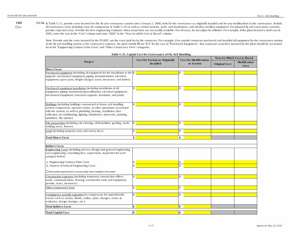
Steam Electric Questionnaire Part C. Ash Handling
CBI? C2-34.
Original CostModification
Cost
$ $
$ $
$ $
$ $
$ $
$ $
$ $
$ $
$ $
$ $
$ $
Total Indirect Costs $ $
Total Capital Cost $ $
Total Direct Costs
In Table C-11, provide costs incurred for this fly ash conveyance system since January 1, 2000, both for the conveyance as originally installed and for any modifications to the conveyance. Include
all conveyance costs including costs for components in Table C-10 as well as control systems, pads, and foundations, and all other ancillary equipment. For planned fly ash conveyance systems,
provide expected costs. Provide the best engineering estimates when actual data are not readily available. For all costs, do not adjust for inflation. For example, if the plant incurred a land cost in
2002, enter the cost in the "Cost" column and enter "2002" in the "Year on which Cost is Based" column.
Note: Provide only the costs incurred by the PLANT, not the costs paid for by the contractor. For example, if an outside contractor purchased and installed all equipment for the conveyance portion
of the fly ash handling system at the contractor's expense, the plant should fill out "$ 0" for the cost of "Purchased Equipment". Any contractor costs/fees incurred by the plant should be accounted
for in the "Engineering Contract Firm Costs" and "Other Contractor's Fees" categories.
Indirect Costs
Table C-11. Capital Cost for Conveyance of Fly Ash Handling
Purchased equipment (including all equipment for the installation or the
upgrade: mechanical equipment; piping; instrumentation; electrical
equipment; spare parts; freight charges; taxes; insurance; and duties)
Purchased equipment installation (including installation of all
equipment; piping; instrumentation/calibration; electrical equipment;
mechanical equipment; structural supports, insulation, and paint)
ProjectCost for System as Originally
Installed
Cost for Modifications
to System
Buildings (including buildings constructed to house ash handling
system components, operator rooms, or other operations associated
with the system; as well as plumbing, heating, ventilation, dust
collection, air conditioning, lighting, telephones, intercoms, painting,
sprinklers, fire alarms)
Direct Costs
Year on Which Cost is Based
Construction expenses (including temporary construction offices,
roads, communications, fencing; construction tools and equipment;
permits, taxes, insurance)
Other Contractor's Fees
Contingency actually expended (to compensate for unpredictable
events such as storms, floods, strikes, price changes, errors in
estimates, design changes, etc.)
Engineering Costs (including process design and general engineering,
cost engineering, consulting fees, supervision, inspection for each
category below)
a. Engineering Contract Firm Costs
b. Owner's Overhead Engineering Costs
Site preparation (including site clearing, all demolition, grading, roads,
walking areas, fences)
Land (including property costs and survey fees)
Yes
Hired outside engineering firm to oversee design and/or installation of the system.
C-17 Approved: May 20, 2010

Steam Electric Questionnaire Part C. Ash Handling
CBI? C2-35.
(Skip to Question C2-36)
(Continue)
CBI? C2-36.
No. of workers
$ $ hpd
dpy
No. of workers
$ $ hpd
dpy
$
$ $ per kWh kWh/hr
Other: $
Other: $
$
Provide annual (2009) O&M costs data in Table C-12 for this fly ash conveyance system, if it began operating or was converted on or after January 1, 2000. Provide best engineering estimates
when actual data are not readily available. If you provide an estimate, note the methods that were used to make the estimates in the Comments page.
Note: Provide only the cost data incurred by the PLANT, not the costs paid for by the contractor. For example, if an outside contractor operates and maintains the intermediate storage portion of
the fly ash handling system at the contractor's expense, the plant should fill out "$ 0" for O&M costs. Any contractor costs/fees incurred by the plant should be accounted for in the Table C-11
"Engineering Contract Firm Costs" and "Other Contractor's Fees" categories.
Table C-12. O&M Cost for Conveyance of Fly Ash Handling for 2009
O&M Cost Category 2009 Annual Cost 2009 Rate
Total O&M Cost (2009)
Maintenance Labor
Per hour (average
rate of labor)
2009 Staffing/Consumption
Maintenance Materials
Energy
Operating Labor
Per hour (average
rate of labor)
Are all major components of the conveyance portion of the fly ash handling system included in the capital costs reported in Table C-11?
Please explain what system components are included in the capital costs listed in Table C-11. Additionally, identify the key components of the conveyance portion of the fly
ash handling system that are not included in the capital costs reported in Table C-11.
Yes
Yes Yes
No
C-18 Approved: May 20, 2010

Steam Electric Questionnaire Part C. Ash Handling
Plant ID: Insert Plant ID
Plant Name: Insert Plant Name
Storage ID Insert Storage ID
Part: C
Section Title:
Instructions:
CBI? C2-37.
Provide unit IDs, as assigned in A-8, contributing bottom ash to this storage component.
CBI? C2-38.
(Skip to Section 2.5)
(Continue)
2.4. Fly Ash Cost Information - Intermediate Storage
Complete Section 2.4 (Questions C2-37 through C2-44) for each intermediate storage destination identified in Table C-6 that began operating or was modified after January 1, 2000. Enter the
storage ID in the space provided above (use the storage IDs assigned in Table C-6).
If you indicated in Question C2-17 or C2-18 that the plant is either installing or planning to install dry fly ash handling for this unit, complete Section 2.4, and check the "Planned" checkbox
below.
Make copies of Section 2.4 for each fly ash handling system operated in 2009, that began operating on or after January 1, 2000, is being installed, or planned to be installed by December 31,
2020 using the "Copy Section 2.4" button below.
Is this storage destination a pond/impoundment ?
Does this storage component store both fly and bottom ash together? For example, if bottom ash and fly ash are conveyed separately but stored in a common silo, the silo is considered a
shared component.
If you are instructed to skip forward to another section while completing this section for one fly ash storage destination, be sure to complete this section for all other fly ash storage destinations
operated in 2009, being installed, or planned to be installed by December 31, 2020.
The intermediate storage portion of the fly ash handling system refers to the facility/site where collected fly ash is stored after conveyance, prior to the ash being transported to final disposal.
Dry fly ash intermediate storage typically consists of storage silos. Wet fly ash intermediate storage typically consists of ponds/impoundments.
Note that intermediate storage includes all equipment and operations associated with loading dry or moisture-conditioned ash into trucks or rail cars for transport (but does not include the
actual transport). Intermediate storage also includes all ash dust suppression activities at the plant, expect those at a pond/impoundment or landfill.
Yes
Copy Section 2.4
Yes
Yes
No
Yes
No
Planned
C-19 Approved: May 20, 2010

Steam Electric Questionnaire Part C. Ash Handling
CBI? C2-39.
Number of Components in the
System
Other: If other, specify:
Other: If other, specify:
Other: If other, specify:
Other: If other, specify:
Other: If other, specify:
Other: If other, specify:
Other: If other, specify:
Other: If other, specify:
CBI? C2-40.
CBI? C2-41.
Table C-13. Fly Ash Handling System Components - Intermediate Storage
Total System Capacity of ComponentsType of Component
Identify the major components of the intermediate storage portion of the fly ash handling system, in particular those components that represent a significant portion of the capital or O&M costs
for the system. Provide the type of component and the number of each type of component in the system. Additionally, provide the total system capacity of each component (i.e., volume of
silos). Total system capacity should equal the sum of the capacity of each individual component within that type.
List all of the major components of this intermediate storage destination that a contractor(s) constructed/installed (or will construct/install, for planned systems) at the contractor's expense (i.e.,
not at the plant's expense).
List all of the operation and maintenance activities associated with this intermediate storage destination that a contractor(s) oversees (or will oversee, for planned systems) at the contractor's
expense (i.e., not at the plant's expense).
Yes
Fly Ash Intermediate Storage Components
Fly Ash Intermediate Storage Components
Fly Ash Intermediate Storage Components
Fly Ash Intermediate Storage Components
Fly Ash Intermediate Storage Components
Fly Ash Intermediate Storage Components
Fly Ash Intermediate Storage Components
Fly Ash Intermediate Storage Components
Yes
Contractor oversees/will oversee ALL operation and maintenance activities dealing with the intermediate storage portion of the fly ash handling system at the contractor's expense .
Yes
Contractor installed/will install ALL components identified in Table C-13 at the contractor's expense.
Component Units
Component Units
Component Units
Component Units
Component Units
Component Units
Component Units
Component Units
C-20 Approved: May 20, 2010

Steam Electric Questionnaire Part C. Ash Handling
CBI? C2-42.
Original Cost Modification
Cost
$ $
$ $
$ $
$ $
$ $
$ $
$ $
$ $
$ $
$ $
$ $
Total Indirect Costs $ $
Total Capital Cost $ $
Total Direct Costs
Project Cost for System as Originally
Installed
Cost for Modifications
to System
Year on Which Cost is Based
Direct Costs
Purchased equipment (including all equipment for the installation or
the upgrade: mechanical equipment; piping; instrumentation;
electrical equipment; spare parts; freight charges; taxes; insurance;
and duties)
Land (includes property costs and survey fees)
Site preparation (includes site clearing, all demolition, grading, roads,
walking areas, fences)
Engineering Costs (including process design and general
engineering, cost engineering, consulting fees, supervision,
inspection for each category below)
a. Engineering Contract Firm Costs
b. Owner's Overhead Engineering Costs
Indirect Costs
Provide cost data in Table C-14 for this intermediate storage destination, both for the storage as originally installed and for any modifications to the storage system, since January 1, 2000.
Include all intermediate storage costs including costs for components in Table C-13 as well as control systems, pads and foundations, and all other ancillary equipment. For planned storage
systems, provide expected costs. Provide the best engineering estimates when actual data are not readily available. For all costs, do not adjust for inflation. For example, if the plant incurred a
land cost in 2002, enter the cost in the "Cost" column and enter "2002" in the "Year on which Cost is Based" column.
Note: Capital costs associated with ponds/impoundments are requested in Part D and capital costs associated with landfills/landfilling are requested in Part F. Do NOT include the costs for
ponds and landfills in Table C-14.
Note: Provide only the cost data incurred by the PLANT, not the costs paid for by the contractor. For example, if an outside contractor purchased all rail cars and/or trucks for the transportation
of the fly ash at the contractor's expense, the plant should fill out "$ 0" for the cost of "Purchased Equipment". Any contractor costs/fees incurred by the plant should
be accounted for in the "Engineering Contract Firm Costs" and "Other Contractor's Fees" categories.
Construction expenses (including temporary construction offices,
roads, communications, fencing; construction tools and equipment;
permits, taxes, insurance)
Other Contractor's Fees
Contingency actually expended (to compensate for unpredictable
events such as storms, floods, strikes, price changes, errors in
estimates, design changes, etc.)
Table C-14. Capital Cost for Intermediate Storage of Fly Ash Handling
Purchased equipment installation (including installation of all
equipment; piping; instrumentation/calibration; electrical equipment;
mechanical equipment; structural supports, insulation, and paint)
Buildings (including buildings constructed to house ash handling
system components, operator rooms, or other operations associated
with the system; as well as plumbing, heating, ventilation, dust
collection, air conditioning, lighting, telephones, intercoms, painting,
sprinklers, fire alarms)
Yes
Hired outside engineering firm to oversee design and/or installation of the system.
C-21 Approved: May 20, 2010

Steam Electric Questionnaire Part C. Ash Handling
CBI? C2-43.
(Skip to Question C2-44)
(Continue)
CBI? C2-44.
No. of workers
$ $ hpd
dpy
No. of workers
$ $ hpd
dpy
No. of workers
$ $ hpd
dpy
$
$ $ per kWh kWh/hr
Other: $
Other: $
$
Provide annual O&M costs data in Table C-15 for this intermediate storage destination, if it began operating or was modified on or after January 1, 2000. Provide best engineering estimates
when actual data are not readily available. If you provide an estimate, note the methods that were used to make the estimates in the Comments page.
Note: O&M costs associated with ponds/impoundments are requested in Part D and O&M costs associated with landfills/landfilling are requested in Part F. Do NOT include the costs for ponds
and landfills costs in Table C-15.
Note: Provide only the cost data incurred by the PLANT, not the costs paid for by the contractor. For example, if an outside contractor operates and maintains the intermediate storage portion
of the fly ash handling system at the contractor's expense, the plant should fill out "$ 0" for O&M costs. Any contractor costs/fees incurred by the plant should be accounted for in the Table C-
14 "Engineering Contract Firm Costs" and "Other Contractor's Fees" categories.
Table C-15. O&M Cost for Intermediate Storage of Fly Ash Handling for 2009
O&M Cost Category 2009 Annual Cost 2009 Rate
Total O&M Cost (2009)
Maintenance Labor
Per hour (average
rate of labor)
Maintenance Materials
Energy
Operating Labor (Water Trucks Only)
Per hour (average
rate of labor)
Operating Labor (All other operating costs)
Per hour (average
rate of labor)
2009 Staffing/Consumption
Are all major components of the intermediate storage destination included in the capital costs reported in Table C-14?
Please explain what system components are included in the capital costs listed in Table C-14. Additionally, identify the key components intermediate storage destination that
are not included in the capital costs reported in Table C-14.
Yes
YesYes
No
C-22 Approved: May 20, 2010

Steam Electric Questionnaire Part C. Ash Handling
Plant ID: Insert Plant ID
Plant Name: Insert Plant Name
Part: C
Section Title:
Instructions:
CBI? C2-45.
Provide unit IDs, as assigned in A-8, and storage IDs, provided in Table C-6, contributing bottom ash to the transport and disposal system.
(Continue)
CBI? C2-46.
(Skip to Section 3.1)
(Continue)
2.5. Fly Ash Cost Information - Transport/Disposal
Complete Section 2.5 (Questions C2-45 through C2-52) for all transport/disposal of fly ash from fly ash handling systems that began operating or was modified after January 1, 2000, and those systems being installed, or planned
to be installed by December 31, 2020.
Is a pond/impoundment unit or pond/impoundment system the final destination of all fly ash collected by the plant?
Does the plant use the same transport and disposal equipment for both fly and bottom ash? For example, if fly ash and bottom ash are transported using the same trucks, the trucks are considered a shared component.
The transport/disposal portion of the fly ash handling system refers to the transportation of fly ash from intermediate storage to final disposal.
An example of ash transport/disposal is transportation used to haul ash off site (e.g., ash that is marketed and shipped off site to a reuse application). Ash transport typically
consists of roads and vehicles that are used to transport the ash. The capital and O&M costs for ash transport/disposal may include the road or rail infrastructure (roads,
tracks, lights), the trucks and rail cars, the operation and maintenance costs associated with the trucks and rail cars, and ash disposal fees.
Note that capital and operation and maintenance costs associated with ponds/impoundments and landfills/landfilling are requested in Parts D and F, respectively, and they should not be provided here in Section 2.5.
Yes
Yes
Yes
No
Yes
No
C-23 Approved: May 20, 2010

Steam Electric Questionnaire Part C. Ash Handling
CBI? C2-47.
How many trucks does the plant use for the transportation and disposal of dry fly ash?
Indicate whether the trucks were bought, leased or contracted out.
How many rail cars does the plant use for the transportation and disposal of dry fly ash?
Indicate whether the rail cars were bought, leased or contracted out.
CBI? C2-48.
CBI? C2-49.
List all of the major components for transport/disposal of fly ash that a contractor(s) constructed/installed (or will construct/install, for planned systems) at the contractor's expense (i.e., not at the plant's expense).
List all of the operation and maintenance activities for transport/disposal of fly ash that a contractor(s) oversees (or will oversee, for planned systems) at the contractor's expense (i.e., not at the plant's expense).
What methods are used to transport the collected fly ash to the final disposal? [Check all boxes that apply.]Yes
Trucks
Rail cars
Other, specify (e.g., barge):
Contractor oversees/will oversee ALL transport/disposal activities at the contractor's expense.
Yes
Yes
Contractor installed/will install ALL ash transport/disposal equipment and/or infrastructure at the contractor's expense.
Leased
Contracted out
Bought
Leased
Contracted out
Bought
C-24 Approved: May 20, 2010

Steam Electric Questionnaire Part C. Ash Handling
CBI? C2-50.
Original CostModification
Cost
$ $
$ $
$ $
$ $
$ $
$ $
$ $
$ $
$ $
$ $
$ $
$ $
Total Capital Cost $ $
Cost for System as Originally Installed
Cost for
Modifications to
System
Year on Which Cost is Based
Provide cost data in Table C-16 for the transport/disposal of the collected fly ash, both for the transport/disposal as originally installed and for any modifications, since January 1, 2000. For planned transport/disposal systems,
provide expected costs. Provide the best engineering estimates when actual data are not readily available. For all costs, do not adjust for inflation. For example, if the plant incurred a land cost in 2002, enter the cost in the "Cost"
column and enter "2002" in the "Year on which Cost is Based" column.
Note: Capital costs associated with ponds/impoundments are requested in Part D and capital costs associated with landfills/landfilling are requested in Part F. Do NOT include the costs for ponds and landfills in Table C-16.
Note: Provide only the cost data incurred by the PLANT, not the costs paid for by the contractor. For example, if an outside contractor purchased all rail cars and/or trucks for the transportation of the fly ash at the contractor's
expense, the plant should fill out "$ 0" for the cost of "Purchased Equipment". Any contractor costs/fees incurred by the plant should be accounted for in the "Engineering Contract Firm Costs" and "Other Contractor's Fees"
categories.
Table C-16. Capital Cost for Transport/Disposal of Collected Fly Ash
Project
Land (includes property costs and survey fees)
Site preparation (including site clearing, all demolition, grading,
roads, walking areas, fences)
Direct Costs
Purchased equipment (including all equipment for the
installation or the upgrade: mechanical equipment; piping;
instrumentation; electrical equipment; spare parts; freight
charges; taxes; insurance; and duties)
Purchased equipment installation (including installation of all
equipment; piping; instrumentation/calibration; electrical
equipment; mechanical equipment; structural supports,
insulation, and paint)
Buildings (including buildings constructed to house ash
handling system components, operator rooms, or other
operations associated with the system; as well as plumbing,
heating, ventilation, dust collection, air conditioning, lighting,
telephones, intercoms, painting, sprinklers, fire alarms)
Construction expenses (includes temporary construction offices,
roads, communications, fencing; construction tools and
equipment; permits, taxes, insurance)
Other Contractor's Fees
Contingency actually expended (to compensate for
unpredictable events such as storms, floods, strikes, price
changes, errors in estimates, design changes, etc.)
Total Indirect Costs
a. Engineering Contract Firm Costs
b. Owner's Overhead Engineering Costs
Total Direct Costs
Indirect Costs
Engineering Costs (including process design and general
engineering, cost engineering, consulting fees, supervision,
inspection for each category below:
Yes
Hired outside engineering firm to oversee design and/or installation of the system.
C-25 Approved: May 20, 2010

Steam Electric Questionnaire Part C. Ash Handling
CBI? C2-51.
(Skip to Question C2-52)
(Continue)
CBI? C2-52.
No. of workers
$ $ hpd Loads per day
dpy dpy
No. of workers
$ $ hpd
dpy
No. of workers
$ $ hpd
dpy
$
$ $ per kWh kWh/hr
$
Other: $
Other: $
$
Provide annual O&M costs data in Table C-17 for the transport/disposal of the collected fly ash from ash handling systems that began operating on or after January 1, 2000. Provide best engineering estimates when actual data are
not readily available. If you provide an estimate, note the methods that were used to make the estimates in the Comments page.
Note: O&M costs associated with ponds/impoundments are requested in Part D and O&M costs associated with landfills/landfilling are requested in Part F. Do NOT include the costs for ponds and landfills in Table C-17.
Note: Provide only the cost data incurred by the PLANT, not the costs paid for by the contractor. For example, if an outside contractor operates the transportation and disposal of the ash at the contractor's expense, the plant should
fill out "$ 0" for the cost of all operating O&M costs. Any contractor costs/fees incurred by the plant should be accounted for in the Table C-16 "Engineering Contract Firm Costs" and "Other Contractor's Fees" categories.
Are all major components of transport/disposal for the fly ash handling system included in the capital costs reported in Table C-16?
Please explain what system components are included in the capital costs listed in Table C-16. Additionally, identify the key components of transport/disposal for the fly ash handling system that are not included in the capital costs
reported in Table C-16.
Operating Labor (All other operating costs) Per hour
(average rate
of labor)
Total O&M Cost (2009)
Maintenance Labor Per hour
(average rate
of labor)
Maintenance Materials
Energy
Ash Removal/Disposal Fees
Operating Labor (Trucks/Rail Cars/Other Transport) Per hour
(average rate
of labor)
Table C-17. O&M Cost for Transport/Disposal of the Fly Ash for 2009
O&M Cost Category 2009 Annual Cost 2009 Rate 2009 Staffing/Consumption Transport Rate
Yes
Yes Yes
No
C-26 Approved: May 20, 2010

Steam Electric Questionnaire Part C. Ash Handling
Plant ID:
Plant Name:
SE Unit ID:
Part: C
Section Title: 3.1. Bottom Ash Handling - Generating Unit Level Information
Instructions:
CBI? C3-1.
(Continue)
CBI? C3-2.
●
● Refer to the glossary and the "Part C Instructions" tab for definitions related to wet and dry bottom ash handling systems.
1,500 tpd 0 tpd 30 % % 5 tpd 0 tpd 365 days 0 days 1 to 2 % to %
365 dpy 0 dpy 5 dpy 0 dpy
Other:
tpd tpd % % tpd tpd days daysto % to %
dpy dpy dpy dpy
Other:
Throughout Section 3.1 (Questions C3-1 through C3-31), provide ash handling information for each steam electric generating unit operated at any time in 2009, including units that may have been idle for an extended period of time. Make
copies of Section 3.1 for each steam electric generating unit using the "Copy Section 3.1" button below. Enter the steam electric generating Unit ID (use Unit IDs assigned in Table A-8) in the space above titled "SE Unit ID".
Typical Amount of Bottom Ash
Produced in 2009
(Dry weight basis)
Wet Conveyed Dry Conveyed
Type of Bottom Ash
Handling System
Insert Unit ID
Dry ConveyedDry
Conveyed
Wet ConveyedWet
Conveyed
Loss on Ignition of Bottom
Ash Produced (Provide typical
range for 2009)
Typical Percent Moisture
of Bottom Ash in 2009
Design Ash Handling Rate
(Dry weight basis)
Wet Conveyed
Number of Days Ash
was Handled by the
Bottom Ash Handling
System in 2009
Wet
Conveyed
Dry
Conveyed
Table C-18. Bottom Ash Handling Systems Operated in 2009 by Generating Unit
Provide bottom ash handling information in Table C-18, for each steam electric generating unit reported in Table A-8, following these instructions:
Provide bottom ash handling information at the steam electric generating unit level. For the purpose of this questionnaire, more than one type of bottom ash handling (e.g., wet sluicing, SCC) may be selected
for one generating unit. Check all types of bottom ash handling that apply to this steam electric generating unit.
Type of Boiler
Insert Plant ID
Insert Plant Name
Dry
Conveyed
Is bottom ash generated in any fossil-fueled steam electric generating units at the plant? See Part A Section 8 for steam electric generating unit fuel classifications.
(Skip to Section 4)
Yes
Wet-bottom
Type of Boiler
Not monitored Not monitored
Not monitored Not monitored
YesYes
Yes
No
Wet sluicing
Mechanical drag system
Dry vacuum
Dry pressure
Other:
Wet sluicing
Mechanical drag system
Dry vacuum
Dry pressure
Other:
NA NA
NA NA
NA NA
NA NA
C-27 Approved: May 20, 2010

Steam Electric Questionnaire Part C. Ash Handling
CBI? C3-3.
(Continue)
(Skip to Question C3-11)
●
●
●
●
●
EXAMPLE:
%
gpd hpd %
dpy %
Other: %
%
gpd hpd %
dpy %
Other: %
CBI? C3-4.
Chlorides concentration, less than: ppm
Solids percentage, less than: %
Other: ppm
CBI? C3-5.
(Continue)
(Skip to Question C3-6)
Percent Contribution
of Source to Sluice
Water Flow
“IN” if raw intake water is used;
“IN-Makeup” if raw intake water is only used as makeup;
“TR” for use of intake water that has been treated on site prior to use;
90
1014,400,000
Table C-19. Process Wastewater Generated from Wet Bottom Ash Handling in 2009
Typical Duration
AND Frequency of
Sluicing (hpd AND
dpy)
24
An example is provided in Table C-19 for a plant that uses the effluent from its ash pond (WWT-1, as would be defined in Part A) for bottom ash sluicing and also makes up for losses with untreated river water (which is
code IN-Makeup as shown above).
For water sources that may be used as a source of bottom ash sluice water (e.g., fresh intake, recycled process water), indicate the maximum chlorides concentration and the maximum solids percentage that is acceptable
for the water to be used for those purposes. [Check all boxes that apply.]
Process wastewater and/or treated wastewater described the code tables on the "Code Tables" tab provided at the end of this workbook.
365
Provide information for the wet bottom ash handling system in Table C-19. For the source of sluice water, you may enter more than one source from the following options:
“TR-Makeup” if treated intake water is used only as makeup; and/or
Is any of the wet bottom ash sluice water immediately recycled (e.g., without treatment such as a pond) back to plant process?
Describe how the wet bottom ash sluice is reused:
Average Sluice Water Flow Rate (gpd) Source(s) of Sluice Water
Is wet sluicing used to collect bottom ash for this steam electric generating unit?
YesYes
No
WWT-1 Effluent
IN-Makeup
Sluice Water Source
Sluice Water Source
Sluice Water Source
Sluice Water Source
Yes
No
Yes
YesYes
No
C-28 Approved: May 20, 2010

Steam Electric Questionnaire Part C. Ash Handling
CBI? C3-6.
CBI? C3-7.
(Continue)
(Skip to Question C3-11)
CBI? C3-8.
tons %
tons %
tons %
tons %
tons %
tons %
CBI? C3-9.
gpd
CBI? C3-10.
Provide the amount of wastewater overflow that is recycled.
gpd
Describe how the wastewater overflow is reused:
Table C-20. Wet Ash Sluice Systems Operated in 2009
Provide the amount of wastewater overflow from solids removal (e.g., dewatering bins) for the wet ash sluice system.
Solids Removal [Check all
boxes that apply]
Amount (tons)
of Solids
Disposed (Dry
weight basis)
Typical
Percent
Moisture of
Bottom Ash
Disposed
Bottom Ash Disposal [Check all boxes that apply]
Does solids removal (other than in pond(s)/impoundment(s)) occur at the plant?
What is the destination(s) of the wastewater overflow from solids removal? If the plant recycles the wastewater, indicate the amount and the plant process to which this waste is recycled. [Check all boxes that apply.]
In Table C-20 provide solids removal information, on a dry ton basis, for the wet ash sluice system. For the purpose of Table C-20, solids removal does NOT include ash ponds.
Is any of the wet bottom ash sluice indirectly discharged to a publicly or privately owned treatment works?
Yes
No
Yes
No
Yes
Yes
No
Yes
Dewatering bin
Hydrocyclones
Centrifuges
Filters
Other:
Sold or given away without further treatment
Sold or given away after further treatment
Other:
Stored in/transferred to a pond/impoundment reported in Table A-4
Stored in landfills reported in Table A-6
Stored in landfills NOT reported in Table A-6
Yes
Yes
Settling pond Constructed wetlands
pH adjustment Other, specify:
Immediately recycled back to plant process.
Transferred to on-site treatment system. Identify the type of treatment system below. [Check all boxes that apply.]
Discharged to surface water. Provide NPDES permitted outfall number (from Part A Section 2.2):
Indirect discharge to a publicly or privately owned treatment works
Other, explain:
Yes
C-29 Approved: May 20, 2010

Steam Electric Questionnaire Part C. Ash Handling
CBI? C3-11.
(Continue)
(Skip to Question C3-15)
CBI? C3-12.
(Continue)
(Skip to Question C3-15)
CBI? C3-13.
gpd
CBI? C3-14.
Provide the amount of wastewater overflow that is recycled.
gpd
Describe how the wastewater overflow is reused:
Does the plant use a mechanical drag system (e.g., submerged chain conveyor (SCC)) to remove bottom ash from this generating unit boiler?
Is any process wastewater generated from overflow, or other means, from the mechanical drag system?
Provide the amount of wastewater overflow from the mechanical drag system.
Name the type and describe the process of removing bottom ash from the generating unit boiler(s).
What is the destination(s) of the wastewater overflow from the mechanical drag system? If the plant recycles the wastewater, indicate the amount and the plant process to which this waste is recycled. [Check all boxes that
apply.]
Yes
Yes
Yes
Yes
Settling pond Constructed wetlands
pH adjustment Other, specify:
Immediately recycled back to plant process.
Transferred to on-site treatment system. Identify the type of treatment system below. [Check all boxes that apply.]
Discharged to surface water. Provide NPDES permitted outfall number (from Part A Section 2.2):
Indirect discharge to a publicly or privately owned treatment works
Other, explain:
Yes
No
Yes
No
C-30 Approved: May 20, 2010

Steam Electric Questionnaire Part C. Ash Handling
CBI? C3-15.
% %
If other, explain:
% %
If other, explain:
% %
If other, explain:
% %
If other, explain:
% %
If other, explain:
% %
CBI? C3-16.
(Continue)
(Skip to Question C3-19)
CBI? C3-17.
days
days
days
days
days
CBI? C3-18.
Percent of Dry
Conveyed Bottom
Ash to this
Destination
If other, explain:
If other, explain:
Storage Destination(s)
What modifications would be required to handle all the bottom ash with a dry bottom ash handling system? [Check all boxes that apply.]
If other, explain:
If other, explain:
Table C-21. Storage Destinations that Receive Bottom Ash
Total Dry 100Total Wet
Destination Type Percent of Wet Conveyed
Bottom Ash to this
Destination
In Table C-21, identify the destination(s) for wet and dry bottom ash transferred from the hopper(s) of this steam electric generating unit. Provide the distribution of the wet and dry ash by destination and whether the storage
indentified is an intermediate or final destination.
Note: The sum of the percentage of ash distribution should equal 100% for the dry and wet bottom ash, separately.
If other, explain:
Storage Destination(s)
Dry Conveyed Bottom Ash Wet Conveyed Bottom Ash
Destination Type
Was the bottom ash from this steam electric generating unit conveyed both wet and dry in 2009?
100
Indicate why bottom ash from the steam electric generating unit was conveyed both wet and dry in 2009. [Check all boxes that apply.] For each selection, identify the number of days in 2009 the wet system was operated
for this reason.
YesYes
Storage Destination Table
Storage Destination Table
Storage Destination Table
Storage Destination Table
Storage Destination Table
Yes
Yes
No
YesYes
Storage Destination Table
Storage Destination Table
Storage Destination Table
Storage Destination Table
Storage Destination Table
Yes
Yes
No
Yes
Wet bottom ash handling system operated during times in which the dry collected bottom ash was not marketable.
Wet bottom ash handling system operated when the dry bottom ash collection system was not operational due to maintenance issues.
Wet bottom ash handling system operated in order to maintain its function as a backup to the dry system (i.e., wet system operated to ensure that it is still functional.)
Wet bottom ash handling system operated because the dry bottom ash handling system does not have the capacity to handle all of the bottom ash.
Other, explain:
Yes
Increase the capacity of the silo(s).
Increase the number of silos.
Other, explain:
Modify the loading silos to have the ability to moisture condition the ash.
Increase the capacity of the dry bottom ash conveying equipment.
Install/increase the capacity of landfills.
Design/develop new infrastructure to dispose of dry ash. Specify the new infrastructure needed:
No system modifications necessary. Procedural changes would be sufficient.
Intermediate
Final
Intermediate
Final
Intermediate
Final
Intermediate
Final
Intermediate
Final
Intermediate
Final
Intermediate
Final
Intermediate
Final
Intermediate
Final
Intermediate
Final
C-31 Approved: May 20, 2010

Steam Electric Questionnaire Part C. Ash Handling
CBI? C3-19.
(expected operating days per year for wet system)
(expected end date)
CBI? C3-20.
(Skip to Question C3-24)
(Skip to Question C3-24)
(Continue)
Year Built:
CBI? C3-21.
(Skip to Question 3-29)
(Continue)
(Continue)
CBI? C3-22.
Installation of pressure/vacuum system and piping
Boiler alteration to accommodate the mechanical drag system
Expansion of pressure/vacuum system and piping
Installation of storage silos
Modification of the silos to moisture-condition the ash
Modification of the silos for ash transfer to rail cars
Modification of the silos for marketable ash
Construction of haul roads
Construction of rail track
Construction of landfill. Provide the landfill ID(s) from Table A-6:
Increasing landfill capacity. Provide the landfill ID(s) from Table A-6:
Changes in personnel/training, explain:
Storage of ash in landfills. Provide the landfill ID(s) from Table A-6:
Marketing of ash
Hauling ash to off-site storage
Dust suppression activities
Other, explain:
Changes in ash disposal practices
What type of retrofit was the dry bottom ash handling system?
Changes to air permit
Other, explain:
If the current bottom ash handling operations for the steam electric generating unit are expected to significantly change by December 31, 2020, indicate how (i.e., convert to or add dry handling capability). [Check all boxes
that apply.]
Physical changes to facility
Shutdown time (days) required to bring dry bottom ash handling system on line:
Was a generating unit outage(s), outside of regularly scheduled outages, required to bring the dry bottom ash handling system on line?
Was the dry bottom ash handling installed as a retrofit to the steam electric generating unit?
Describe the changes that were required to retrofit (for a retrofit to an existing dry system, an installation of a dry system, or a complete conversion from wet to dry). [Check all boxes that apply.]
Yes
Yes
Yes
Yes
Decreased use of wet bottom ash handling system.
No change expected in bottom ash handling operations.
End use of wet bottom ash handling system.
Other, explain:
Expand capacity (handling and/or storage).
NA, this unit does not use dry bottom ash handling
No
Yes
Yes
No
The retrofit was made to an existing dry system.
A dry bottom ash handling system was installed (for operation in addition to the wet fly ash handling system).
The retrofit was a complete conversion from a wet to dry bottom ash handling system.
Yes
Yes
Yes
Yes
C-32 Approved: May 20, 2010

Steam Electric Questionnaire Part C. Ash Handling
CBI? C3-23.
CBI? C3-24.
(Skip to Question C3-26)
(Continue to Question C3-25)
CBI? C3-25.
Estimated shutdown time (days) required to bring dry bottom ash handling system online: (Continue to Question C3-26)
(Skip to Question C3-29)
CBI? C3-26.
CBI? C3-27.
Installation of mechanical drag system
Boiler alteration to accommodate the mechanical drag system
Installation of completely dry bottom ash handling system
Installation of storage silos
Modification of the silos to moisture-condition the ash
Modification of the silos for ash transfer to rail cars
Modification of the silos for marketable ash
Construction of haul roads
Construction of rail track
Construction of landfill. Provide the landfill ID(s) from Table A-6:
Increasing landfill capacity. Provide the landfill ID(s) from Table A-6:
Other, explain:
Changes in personnel/training, explain:
Storage of ash in landfill. Provide the landfill ID(s) from Table A-6:
Marketing of ash
Hauling ash to off-site storage
Dust suppression activities
Other, explain:
Describe the modifications that will be required to install the dry bottom ash handling system. [Check all boxes that apply.]
Physical changes to facility
Attach an engineering process diagram(s) for the dry bottom ash handling system retrofit that depicts (with dimensions) the conveyance portion of the system (e.g., a
diagram(s) that depicts how the dry bottom ash system is configured within the building to convey bottom ash from the boiler(s) to the building exit).
Is the plant planning to install a dry bottom ash handling system to handle some or all of the ash currently handled by the wet bottom ash handling system?
Changes in ash disposal practices
Changes to air permit
Estimated shutdown time (days) required to bring dry bottom ash handling system online:
Is the plant in the process of installing a dry bottom ash handling system to handle some or all of the ash currently handled by the wet bottom ash handling system?
If the plant is in the process of installing, or planning to install, a dry bottom ash handing system by December 31, 2020, provide the cost estimates that have been
developed for such a conversion/installation.
(Provide documentation/costs, for example, bid proposals or internal plant engineering estimates.)
(Skip to Question C3-29)
Note: All bid proposals and/or other documentation/costs originally submitted to the plant as CBI, should be marked CBI for the purpose of this collection
request.
Yes
Diagram attached.
Yes
Yes
Yes
Yes
No
Yes
No
Yes
Yes
No
I have attached documentation/costs.
I did not attach documentation/costs. Below, explain why:
C-33 Approved: May 20, 2010

Steam Electric Questionnaire Part C. Ash Handling
CBI? C3-28.
If other, specify:
If other, specify:
If other, specify:
CBI? C3-29.
CBI? C3-30.
(Continue)
(Skip to Section 3.2)
Stored in landfills reported in Table A-6
Stored in landfills NOT reported in Table A-6
Marketed, sold, and/or given away
Indicate the types of destinations expected for the dry bottom ash from the planned system and the percentage of the dry bottom ash that is expected to go to each destination. [Check all boxes that apply.]
% of the dry bottom ash
% of the dry bottom ash
% of the dry bottom ash
Has the plant encountered any unscheduled outages on this generating unit caused by the bottom ash handling system in the last five years?
% of the dry bottom ash
(Skip to Question C3-30)
Note: All bid proposals and/or other documentation/costs originally submitted to the plant as CBI, should be marked CBI for the purpose of this collection request.
(Provide documentation/costs, for example, bid proposals or internal plant engineering estimates.)
% of the dry bottom ash
If the plant is not in the process of installing or planning to install a dry bottom ash handling system, have cost estimates been obtained/developed since January 1, 1995, for such a conversion/installation?
% of the dry bottom ash
Other, specify:
Yes
Yes
Yes
No
I have attached documentation/costs.
I did not attach documentation/costs. Below, explain why:
Yes
No
Yes
Yes
Yes
No
Yes
Market Destinations
Market Destinations
Market Destinations
C-34 Approved: May 20, 2010

Steam Electric Questionnaire Part C. Ash Handling
CBI? C3-31.
Dry
Wet
Dry
Wet
Dry
Wet
Dry
Wet
2006
2007
2008
2009
2005
Year Ash Handling
Dry
Wet
Method(s) Used to Resolve Outage(s)
In Table C-22, provide information on unscheduled generating unit outages caused by bottom ash handling for each of the last five years.
Total Days of
Outage
Reason(s) for outage(s)
Table C-22. Unscheduled Generating Unit Outages Caused by Bottom Ash Handling
Yes
C-35 Approved: May 20, 2010
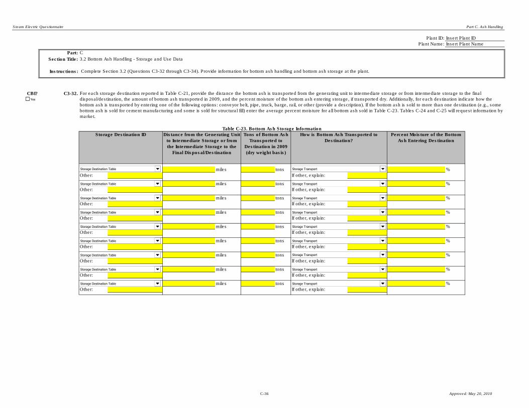
Steam Electric Questionnaire Part C. Ash Handling
Plant ID:
Plant Name:
Part: C
Section Title: 3.2 Bottom Ash Handling - Storage and Use Data
Instructions:
CBI? C3-32.
miles tons %
Other: If other, explain:
miles tons %
Other: If other, explain:
miles tons %
Other: If other, explain:
miles tons %
Other: If other, explain:
miles tons %
Other: If other, explain:
miles tons %
Other: If other, explain:
miles tons %
Other: If other, explain:
miles tons %
Other: If other, explain:
miles tons %
Other: If other, explain:
Insert Plant Name
Insert Plant ID
Table C-23. Bottom Ash Storage Information
Storage Destination ID Distance from the Generating Unit
to Intermediate Storage or from
the Intermediate Storage to the
Final Disposal/Destination
How is Bottom Ash Transported to
Destination?
Complete Section 3.2 (Questions C3-32 through C3-34). Provide information for bottom ash handling and bottom ash storage at the plant.
For each storage destination reported in Table C-21, provide the distance the bottom ash is transported from the generating unit to intermediate storage or from intermediate storage to the final
disposal/destination, the amount of bottom ash transported in 2009, and the percent moisture of the bottom ash entering storage, if transported dry. Additionally, for each destination indicate how the
bottom ash is transported by entering one of the following options: conveyor belt, pipe, truck, barge, rail, or other (provide a description). If the bottom ash is sold to more than one destination (e.g., some
bottom ash is sold for cement manufacturing and some is sold for structural fill) enter the average percent moisture for all bottom ash sold in Table C-23. Tables C-24 and C-25 will request information by
market.
Percent Moisture of the Bottom
Ash Entering Destination
Tons of Bottom Ash
Transported to
Destination in 2009
(dry weight basis)
Yes
Storage Transport
Storage Transport
Storage Transport
Storage Transport
Storage Transport
Storage Transport
Storage Transport
Storage Transport
Storage Transport
Storage Destination Table
Storage Destination Table
Storage Destination Table
Storage Destination Table
Storage Destination Table
Storage Destination Table
Storage Destination Table
Storage Destination Table
Storage Destination Table
C-36 Approved: May 20, 2010

Steam Electric Questionnaire Part C. Ash Handling
CBI? C3-33.
(Continue)
(Skip to Question C3-34)
Tons (dry basis) Tons
(dry
basis)
Tons
(dry
basis)
%
%
%
%
%
%
%
%
%
%
%
%
%
Other: %
Other: %
Table C-24. Dry Bottom Ash from the Bottom Ash Handling System Marketed/Sold in Calendar Years 2005, 2007, and 2009
Destination Typical Percent
Moisture of Bottom
Ash
2005 2007 2009
Gross
Revenue
Generated
$
Gross Revenue
Generated
$
Gross Revenue
Generated
$
Concrete/Concrete Products/Grout
Blended Cement/Raw Feed for Clinker
Flowable Fill
Structural Fills/Embankments
Road Base/Sub-base
Soil Modification/ Stabilization
Mineral Filler in Asphalt
Snow and Ice Control
Blasting Grit/Roofing Granules
Mining Applications
Waste Stabilization/ Solidification
Agriculture
Aggregate
Complete Table C-24 if the plant markets, sells, and/or gives away dry bottom ash from the bottom ash handling system. For each destination, provide the tons of dry bottom ash marketed, sold, and/or
given away, the gross revenue generated from marketing/selling the dry bottom ash for calendar years 2005, 2007, and 2009. Additionally, provide the typical percent moisture of the bottom ash during
calendar years 2005, 2007, and 2009. If the typical percent moisture of the bottom ash was not constant during calendar years 2005, 2007, and 2009, note this information (include all typical percent
moisture values for each year) in the Comments page.
Does the plant market, sell, and/or give away dry bottom ash from the dry ash handling system?
Yes
No
Yes
C-37 Approved: May 20, 2010

Steam Electric Questionnaire Part C. Ash Handling
CBI? C3-34.
(Continue)
(Skip to Section 3.3)
Tons (dry basis) Tons
(dry
basis)
Tons
(dry
basis)
%
%
%
%
%
%
%
%
%
%
%
%
%
Other: %
Other: %
Does the plant market, sell, and/or give away wet bottom ash from the wet ash handling system?
Destination Typical Percent
Moisture of Bottom
Ash
2005 2007 2009
Flowable Fill
Structural Fills/Embankments
Concrete/Concrete Products/Grout
Blended Cement/Raw Feed for Clinker
Gross
Revenue
Generated
$
Table C-25. Bottom Ash Transported by Wet Sluicing from the Bottom Ash Handling System Marketed/Sold in Calendar Years 2005, 2007, and 2009
Snow and Ice Control
Mineral Filler in Asphalt
Road Base/Sub-base
Soil Modification/ Stabilization
Blasting Grit/Roofing Granules
Gross Revenue
Generated
$
Gross Revenue
Generated
$
Waste Stabilization/ Solidification
Agriculture
Aggregate
Complete Table C-25 if the plant currently markets, sells, and/or gives away bottom ash transported by wet sluicing from the bottom ash handling system. For each destination, provide the tons, on a dry
basis, of bottom ash transported by wet sluicing that is marketed, sold, and/or given away. Also provide the gross revenue generated from marketing/selling the bottom ash transported by wet sluicing for
each destination.
Mining Applications
Yes
No
Yes
C-38 Approved: May 20, 2010

Steam Electric Questionnaire Part C. Ash Handling
Plant ID:
Plant Name:
Unit ID:
Part: C
Section Title: 3.3. Bottom Ash Cost Information - Conveyance
Instructions:
CBI? C3-35.
Number of Components in
the System
Other: If other, specify:
Other: If other, specify:
Other: If other, specify:
Other: If other, specify:
Other: If other, specify:
Other: If other, specify:
Other: If other, specify:
Other: If other, specify:
Insert Plant ID
Insert Plant Name
Insert Unit ID
Complete Section 3.3 (Questions C3-35 through C3-41) for the conveyance of bottom ash (wet or dry) from each unit identified in Table A-8. Provide these data for each bottom ash
handling system that began operating or was converted after January 1, 2000. Enter the Unit ID in the space provided above.
If you indicated in Question C3-24 or C3-25 that the plant is either installing or planning to install dry bottom ash handling for this unit, complete Section 3.3, and check the "Planned"
checkbox below.
Make copies of Section 3.3 for each bottom ash handling system operated in 2009, that began operating on or after January 1, 2000, is being installed, or planned to be installed by
December 31, 2020 using the "Copy Section 3.3" button below.
Note: If any components of the conveyance portion of the bottom ash handling system are shared with one or more other generating units, only report those components and
corresponding costs once.
The conveyance portion of the bottom ash handling system refers to the part of the system that conveys bottom ash from the boiler(s) of the unit to the intermediate or final storage of the
bottom ash. Dry bottom ash handling includes systems that collect and convey the bottom ash without any use of water, as well as systems in which bottom ash is conveyed mechanically
or pneumatically away from a quench water bath (e.g., submerged chain conveyor systems). Wet bottom ash conveyance uses water (i.e., a sluice) to convey bottom ash away from the
boiler to intermediate/final storage (e.g., ponds/impoundments). Note that dewatering bins are considered part of bottom ash conveyance.
Note: Bottom ash conveyance includes all capital and O&M costs required to dredge or empty ponds, dewatering bins, and/or surge tanks to intermediate storage.
Table C-26. Bottom Ash Handling System Components - Conveyance
Total System Capacity of Components
Identify the major components of the conveyance portion of the bottom ash handling system, in particular those components that represent a significant portion of the capital or O&M costs
for the system. Provide the type of component and the number of each type of component in the system. Additionally, provide the total system capacity of each type of component (i.e.,
volume of clarifying tanks). Total system capacity should equal the sum of the capacity of each individual component within that type.
Type of Components
Yes
Copy Section 3.3
Bottom Ash Conveyance Components
Bottom Ash Conveyance Components
Bottom Ash Conveyance Components
Bottom Ash Conveyance Components
Bottom Ash Conveyance Components
Bottom Ash Conveyance Components
Bottom Ash Conveyance Components
Bottom Ash Conveyance Components
Component Units
Component Units
Component Units
Component Units
Component Units
Component Units
Component Units
Component Units
Planned
C-39 Approved: May 20, 2010

Steam Electric Questionnaire Part C. Ash Handling
CBI? C3-36.
CBI? C3-37.
CBI? C3-38. List all of the operation and maintenance activities of this bottom ash conveyance system that a contractor(s) oversees (or will oversee, for planned systems) at the contractor's expense
(i.e., not at the plant's expense).
List all of the major components of this bottom ash conveyance system that a contractor(s) constructed/installed (or will construct/install, for planned systems) at the contractor's expense
(i.e., not at the plant's expense).
Attach a block diagram that shows the entire bottom ash handling system operations for this generating unit. Label the conveyance, intermediate storage (see Part C Section 3.4) and
transport/disposal (see Part C Section 3.5) portions of the system. The diagram should include all key components indicated in Tables C-26 and C-29 and identify all intermediate and final
ash storage destinations. Indicate the movement of ash as well as water through the system. If ash from other generating units is combined with ash from this unit, indicate where the ash is
combined and the portions of the ash handling system involved. Provide as many diagrams as necessary to convey this information. Include the plant name, plant ID, and the unit ID in the
upper right hand corner of the diagram.
Note: If the respondent indicates that the ash is transported to a pond/impoundment, in Question C3-43, the intermediate storage and disposal information will be provided in Part D.
Therefore, the block diagram should only include the conveyance system(s).
Yes
Contractor installed/will install ALL components identified in Table C-26 at the contractor's expense.
Yes
Contractor oversees/will oversee ALL operation and maintenance activities dealing with the conveyance portion of the bottom ash handling system at the contractor's expense.
Yes
Diagram attached.
C-40 Approved: May 20, 2010

Steam Electric Questionnaire Part C. Ash Handling
CBI? C3-39.
Original Cost Modification Cost
$ $
$ $
$ $
$ $
$ $
$ $
$ $
$ $
$ $
$ $
$ $
Total Indirect Costs $ $
Total Capital Cost $ $
Other Contractor's Fees
Contingency actually expended (to compensate for unpredictable
events such as storms, floods, strikes, price changes, errors in
estimates, design changes, etc.)
Engineering Costs (includes process design and general
engineering, cost engineering, consulting fees, supervision,
inspection for each category below)
a. Engineering Contract Firm Costs
b. Owner's Overhead Engineering Costs
Construction expenses (includes temporary construction offices,
roads, communications, fencing; construction tools and equipment;
permits, taxes, insurance)
Indirect Costs
Site preparation (includes site clearing, all demolition, grading,
roads, walking areas, fences)
Land (includes property costs and survey fees)
Total Direct Costs
Direct Costs
Purchased equipment (including all equipment for the installation or
the upgrade: mechanical equipment; piping; instrumentation;
electrical equipment; spare parts; freight charges; taxes; insurance;
and duties)
Purchased equipment installation (including installation of all
equipment; piping; instrumentation/calibration; electrical equipment;
mechanical equipment; structural supports, insulation, and paint)
Buildings (including buildings constructed to house ash handling
system components, operator rooms, or other operations
associated with the system; as well as plumbing, heating,
ventilation, dust collection, air conditioning, lighting, telephones,
intercoms, painting, sprinklers, fire alarms)
In Table C-27, provide capital costs incurred since January 1, 2000, for this bottom ash conveyance system, both for the conveyance as originally installed and for any modifications to the
conveyance. Include all conveyance costs including costs for components in Table C-26 as well as control systems, pads and foundations, and all other ancillary equipment. For planned
bottom ash conveyance systems, provide expected costs. Provide the best engineering estimates when actual data are not readily available. For all costs, do not adjust for inflation. For
example, if the plant incurred a land cost in 2002, enter the cost in the "Cost" column and enter "2002" in the "Year on which Cost is Based" column.
Note: Provide only the costs incurred by the PLANT, not the costs paid for by the contractor. For example, if an outside contractor purchased and installed all equipment for the conveyance
portion of the bottom ash handling system at the contractor's expense, the plant should fill out "$ 0" for the cost of "Purchased Equipment". Any contractor costs/fees incurred by the plant
should be accounted for in the "Engineering Contract Firm Costs" and "Other Contractor's Fees" categories.
Table C-27. Capital Cost for Conveyance of Bottom Ash Handling
Project Cost for System as Originally
Installed
Cost for Modifications
to System
Year on Which Cost is Based
Yes
Hired outside engineering firm to oversee design and/or installation of the system.
C-41 Approved: May 20, 2010

Steam Electric Questionnaire Part C. Ash Handling
CBI? C3-40.
(Skip to Question C3-41)
(Continue)
CBI? C3-41.
No. of workers
$ $ hpd
dpy
No. of workers
$ $ hpd
dpy
$
$ $ per kWh kWh/hr
Other: $
Other: $
$
Maintenance Materials
Are all major components of the conveyance portion of the bottom ash handling system included in the capital costs reported in Table C-27?
Please explain what system components are included in the capital costs listed in Table C-27. Additionally, identify the key components of the conveyance portion of the
bottom ash handling system that are not included in the capital costs reported in Table C-27.
Per hour
(average rate of
labor)
Provide annual (2009) O&M costs data in Table C-28 for this bottom ash conveyance system, if it began operating or was converted on or after January 1, 2000. Provide best engineering
estimates when actual data are not readily available. If you provide an estimate, note the methods that were used to make the estimates in the Comments page.
Note: Provide only the cost data incurred by the PLANT, not the costs paid for by the contractor. For example, if an outside contractor operates and maintains the conveyance portion of the
bottom ash handling system at the contractor's expense, the plant should fill out "$ 0" for O&M costs. Any contractor costs/fees incurred by the plant should be accounted for in the Table C-
27 "Engineering Contract Firm Costs" and "Other Contractor's Fees" categories.
Table C-28. O&M Cost for Conveyance of Bottom Ash Handling for 2009
Energy
Total O&M Cost (2009)
Operating Labor
Per hour
(average rate of
labor)
Maintenance Labor
O&M Cost Category 2009 Annual Cost 2009 Rate 2009 Staffing/Consumption
Yes
Yes Yes
No
C-42 Approved: May 20, 2010

Steam Electric Questionnaire Part C. Ash Handling
Plant ID: Insert Plant ID
Plant Name: Insert Plant Name
Storage ID: Insert Storage ID
Part: C
Section Title:
Instructions:
CBI? C3-42.
Provide unit IDs, as assigned in A-8, contributing fly ash to this storage component. (Skip to Section 3.5)
(Continue)
CBI? C3-43.
(Skip to Section 4)
(Continue)
3.4. Bottom Ash Cost Information - Intermediate Storage
Complete Section 3.4 (Questions C3-42 through C3-49) for each intermediate storage destination identified in Table C-23 that began operating or was modified after January 1, 2000. Enter the
storage ID in the space provided above (use the storage IDs assigned in Table C-23).
If you indicated in Question C3-25 or C3-26 that the plant is either installing or planning to install dry bottom ash handling for this unit, complete Section 3.4, and check the "Planned" checkbox
below.
Make copies of Section 3.4 for each bottom ash handling system operated in 2009, that began operating on or after January 1, 2000, is being installed, or planned to be installed by December
31, 2020 using the "Copy Section 3.4" button below.
Is this storage destination a pond/impoundment?
Does this storage component store both fly and bottom ash together? For example, if bottom ash and fly ash are conveyed separately but stored in a common silo, the silo is considered a
shared component.
If you are instructed to skip forward to another section while completing this section for one bottom ash storage destination, be sure to complete this section for all other bottom ash storage
destinations operated in 2009, being installed, or planned to be installed by December 31, 2020.
The intermediate storage of bottom ash handling refers to the facility/site where collected bottom ash is stored after conveyance, prior to the ash being transported to final disposal. Dry bottom
ash intermediate storage typically consists of storage silos. Wet bottom ash intermediate storage typically consists of ponds/impoundments.
Note that intermediate storage includes all equipment and operations associated with loading dry or moisture-conditioned ash into trucks or rail cars for transport.
Intermediate storage also includes all ash dust suppression activities at the plant.
Yes
Yes
Copy Section 3.4
Yes
No
Planned
Yes
No
C-43 Approved: May 20, 2010

Steam Electric Questionnaire Part C. Ash Handling
CBI? C3-44.
Number of Components in
the System
Other: If other, specify:
Other: If other, specify:
Other: If other, specify:
Other: If other, specify:
Other: If other, specify:
Other: If other, specify:
Other: If other, specify:
Other: If other, specify:
CBI? C3-45.
CBI? C3-46.
Total System Capacity of Components
Table C-29. Bottom Ash Handling System Components - Intermediate Storage
Identify the major components of the intermediate storage portion of the bottom ash handling system, in particular those components that represent a significant portion of the capital or O&M
costs for the system. Provide the type of component and the number of each type of component in the system. Additionally, provide the total capacity of each component (i.e., volume of silos).
Total system capacity should equal the sum of the capacity of each individual component within that type.
Individual Components
List all of the major components of this intermediate storage destination that a contractor(s) constructed/installed (or will construct/install, for planned systems) at the contractor's expense (i.e.,
not at the plant's expense).
List all of the operation and maintenance activities of this intermediate storage destination that a contractor(s) oversees (or will oversee, for planned systems) at the contractor's expense (i.e.,
not at the plant's expense).
Yes
Yes
Yes
Contractor oversees/will oversee ALL operation and maintenance activities dealing with the intermediate storage portion of the bottom ash handling system at the contractor's expense.
Contractor installed/will install ALL components identified in Table C-29 at the contractor's expense.
Bottom Ash Intermediate Storage Components
Bottom Ash Intermediate Storage Components
Bottom Ash Intermediate Storage Components
Bottom Ash Intermediate Storage Components
Bottom Ash Intermediate Storage Components
Bottom Ash Intermediate Storage Components
Bottom Ash Intermediate Storage Components
Bottom Ash Intermediate Storage Components
Component Units
Component Units
Component Units
Component Units
Component Units
Component Units
Component Units
Component Units
C-44 Approved: May 20, 2010
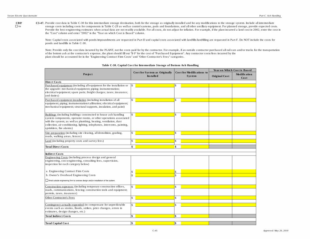
Steam Electric Questionnaire Part C. Ash Handling
CBI? C3-47.
Original CostModification
Cost
$ $
$ $
$ $
$ $
$ $
$ $
$ $
$ $
$ $
$ $
$ $
Total Indirect Costs $ $
Total Capital Cost $ $
Purchased equipment installation (including installation of all
equipment; piping; instrumentation/calibration; electrical equipment;
mechanical equipment; structural supports, insulation, and paint)
Buildings (including buildings constructed to house ash handling
system components, operator rooms, or other operations associated
with the system; as well as plumbing, heating, ventilation, dust
collection, air conditioning, lighting, telephones, intercoms, painting,
sprinklers, fire alarms)
Indirect Costs
Site preparation (including site clearing, all demolition, grading,
roads, walking areas, fences)
Land (including property costs and survey fees)
Total Direct Costs
Direct Costs
Purchased equipment (including all equipment for the installation or
the upgrade: mechanical equipment; piping; instrumentation;
electrical equipment; spare parts; freight charges; taxes; insurance;
and duties)
Construction expenses (including temporary construction offices,
roads, communications, fencing; construction tools and equipment;
permits, taxes, insurance)
Engineering Costs (including process design and general
engineering, cost engineering, consulting fees, supervision,
inspection for each category below)
b. Owner's Overhead Engineering Costs
Other Contractor's Fees
Contingency actually expended (to compensate for unpredictable
events such as storms, floods, strikes, price changes, errors in
estimates, design changes, etc.)
a. Engineering Contract Firm Costs
Cost for Modifications to
System
Year on Which Cost is Based
ProjectCost for System as Originally
Installed
Table C-30. Capital Cost for Intermediate Storage of Bottom Ash Handling
Provide cost data in Table C-30 for this intermediate storage destination, both for the storage as originally installed and for any modifications to the storage system. Include all intermediate
storage costs including costs for components in Table C-29 as well as control systems, pads and foundations, and all other ancillary equipment. For planned storage, provide expected costs.
Provide the best engineering estimates when actual data are not readily available. For all costs, do not adjust for inflation. For example, if the plant incurred a land cost in 2002, enter the cost in
the "Cost" column and enter "2002" in the "Year on which Cost is Based" column.
Note: Capital costs associated with ponds/impoundments are requested in Part D and capital costs associated with landfills/landfilling are requested in Part F. Do NOT include the costs for
ponds and landfills in Table C-30.
Note: Provide only the cost data incurred by the PLANT, not the costs paid for by the contractor. For example, if an outside contractor purchased all rail cars and/or trucks for the transportation
of the bottom ash at the contractor's expense, the plant should fill out "$ 0" for the cost of "Purchased Equipment". Any contractor costs/fees incurred by the
plant should be accounted for in the "Engineering Contract Firm Costs" and "Other Contractor's Fees" categories.
Yes
Hired outside engineering firm to oversee design and/or installation of the system.
C-45 Approved: May 20, 2010

Steam Electric Questionnaire Part C. Ash Handling
CBI? C3-48.
(Skip to Question C3-49)
(Continue)
CBI? C3-49.
No. of workers
$ $ hpd
dpy
No. of workers
$ $ hpd
dpy
No. of workers
$ $ hpd
dpy
$
$ $ per kWh kWh/hr
Other: $
Other: $
$
Maintenance Labor
Per hour
(average rate of
labor)
Operating Labor (Water Trucks Only)
Operating Labor (All other operating costs)
Provide annual O&M costs data in Table C-31 for this intermediate storage destination, if it began operating or was modified on or after January 1, 2000. Provide best engineering estimates
when actual data are not readily available. If you provide an estimate, note the methods that were used to make the estimates in the Comments page.
Note: O&M costs associated with ponds/impoundments are requested in Part D and O&M costs associated with landfills/landfilling are requested in Part F. Do NOT include the costs for ponds
and landfills costs in Table C-31.
Note: Provide only the cost data incurred by the PLANT, not the costs paid for by the contractor. For example, if an outside contractor operates and maintains the intermediate storage portion
of the bottom ash handling system at the contractor's expense, the plant should fill out "$ 0" for O&M costs. Any contractor costs/fees incurred by the plant should be accounted for in the Table
C-30 "Engineering Contract Firm Costs" and "Other Contractor's Fees" categories.
Total O&M Cost (2009)
Energy
Maintenance Materials
Table C-31. O&M Cost for Intermediate Storage of Bottom Ash Handling for 2009
O&M Cost Category 2009 Annual Cost 2009 Rate 2009 Staffing/Consumption
Per hour
(average rate of
labor)
Per hour
(average rate of
labor)
Are all major components of the intermediate storage destination included in the capital costs reported in Table C-30?
Please explain what system components are included in the capital costs listed in Table C-30. Additionally, identify the key components intermediate storage destination
that are not included in the capital costs reported in Table C-30.
Yes
Yes Yes
No
C-46 Approved: May 20, 2010

Steam Electric Questionnaire Part C. Ash Handling
Plant ID: Insert Plant ID
Plant Name: Insert Plant Name
Part: C
Section Title:
Instructions:
CBI? C3-50.
Provide unit IDs, as assigned in A-8, and storage IDs, provided in Table 6, contributing fly ash to the transport and disposal system.
(Skip to Section 4)(Continue)
CBI? C3-51.
(Skip to Section 4)
(Continue)
3.5. Bottom Ash Cost Information - Transport/Disposal
Complete Section 3.5 (Questions C3-50 through C3-57) for all transport and disposal of bottom ash from ash handling systems that began operating or was modified after January 1, 2000, and those systems being installed, or
planned to be installed by December 31, 2020.
The transport/disposal portion of the bottom ash handling system refers to the transportation of bottom ash from intermediate storage to final disposal.
An example of ash transport/disposal is transportation used to haul ash off site (e.g., ash that is marketed and shipped off site to a reuse application). Ash transport typically
consists of roads and vehicles that are used to transport the ash. The capital and O&M costs for ash transport/disposal may include the road or rail infrastructure (roads,
tracks, lights), the trucks and rail cars, the operation and maintenance costs associated with the trucks and rail cars, and ash disposal fees.
Note that capital and operation and maintenance costs associated with ponds/impoundments and landfills/landfilling are requested in Parts D and F, respectively, and they should not be provided here in Section 3.5.
Does the plant use the same transport and disposal methods for both fly and bottom ash? For example, if fly ash and bottom ash are transported using the same trucks, the trucks are considered a shared component.
Is a pond/impoundment unit or pond/impoundment system the final destination of all bottom ash collected by the plant?
Yes
Yes
Yes
No
Yes
No
C-47 Approved: May 20, 2010

Steam Electric Questionnaire Part C. Ash Handling
CBI? C3-52.
How many trucks does the plant use for the transportation and disposal of dry bottom ash?
Indicate whether the trucks were bought, leased or contracted out.
How many rail cars does the plant use for the transportation and disposal of dry bottom ash?
Indicate whether the rail cars were bought, leased or contracted out.
CBI? C3-53.
CBI? C3-54.
List all of the major components for transport/disposal of the bottom ash that a contractor(s) constructed/installed (or will construct/install, for planned systems) at the contractor's expense (i.e., not at the plant's expense).
List all of the operation and maintenance activities for transport/disposal of the bottom ash that a contractor(s) oversees (or will oversee, for planned systems) at the contractor's expense (i.e., not at the plant's expense).
What methods are used to transport the collected bottom ash to the final disposal? [Check all boxes that apply.]Yes
Trucks
Rail cars
Other, specify (e.g., barge):
Contractor oversees/will oversee ALL transport/disposal activities at the contractor's expense.
Yes
Yes
Contractor installed/will install ALL ash transport/disposal equipment and/or infrastructure at the contractor's expense.
Leased
Contracted out
Bought
Leased
Contracted out
Bought
C-48 Approved: May 20, 2010

Steam Electric Questionnaire Part C. Ash Handling
CBI? C3-55.
Original
Cost
Modification
Cost
$ $
$ $
$ $
$ $
$ $
$ $
$ $
$ $
$ $
$ $
$ $
$ $
Total Capital Cost $ $
Land (includes property costs and survey fees)
Provide cost data in Table C-32 for the transport/disposal of the collected bottom ash, both for the transport/disposal as originally installed and for any modifications. For transport/disposal systems, provide expected costs. Provide
the best engineering estimates when actual data are not readily available. For all costs, do not adjust for inflation. For example, if the plant incurred a land cost in 2002, enter the cost in the "Cost" column and enter "2002" in the
"Year on which Cost is Based" column.
Note: Capital costs associated with ponds/impoundments are requested in Part D and capital costs associated with landfills/landfilling are requested in Part F. Do NOT include the costs for ponds and landfills in Table C-32.
Note: Provide only the cost data incurred by the PLANT, not the costs paid for by the contractor. For example, if an outside contractor purchased all rail cars and/or trucks for the transportation of the fly ash at the contractor's
expense, the plant should fill out "$ 0" for the cost of "Purchased Equipment". Any contractor costs/fees incurred by the plant should be accounted for in the "Engineering Contract Firm Costs" and "Other Contractor's Fees"
categories.
Cost for
Modifications
to System
Direct Costs
Year on Which Cost is Based
Site preparation (including site clearing, all demolition,
grading, roads, walking areas, fences)
Cost for System as Originally Installed
Purchased equipment (including all equipment for the
installation or the upgrade: mechanical equipment; piping;
instrumentation; electrical equipment; spare parts; freight
charges; taxes; insurance; and duties)
Purchased equipment installation (including installation of all
equipment; piping; instrumentation/calibration; electrical
equipment; mechanical equipment; structural supports,
insulation, and paint)
Buildings (including buildings constructed to house ash
handling system components, operator rooms, or other
operations associated with the system; as well as plumbing,
heating, ventilation, dust collection, air conditioning, lighting,
telephones, intercoms, painting, sprinklers, fire alarms)
Table C-32. Capital Cost for Transport/Disposal of Collected Bottom Ash
Project
Construction expenses (including temporary construction
offices, roads, communications, fencing; construction tools
and equipment; permits, taxes, insurance)
Other Contractor's Fees
Engineering Costs (including process design and general
engineering, cost engineering, consulting fees, supervision,
inspection for each category below)
b. Owner's Overhead Engineering Costs
Contingency actually expended (to compensate for
unpredictable events such as storms, floods, strikes, price
changes, errors in estimates, design changes, etc.)
Total Indirect Costs
a. Engineering Contract Firm Costs
Total Direct Costs
Indirect Costs
Yes
Hired outside engineering firm to oversee design and/or installation of the system.
C-49 Approved: May 20, 2010

Steam Electric Questionnaire Part C. Ash Handling
CBI? C3-56.
(Skip to Question C3-57)
(Continue)
CBI? C3-57.
No. of workers
$ $ hpd Loads per day
dpy dpy
No. of workers
$ $ hpd
dpy
No. of workers
$ $ hpd
dpy
$
$ $ per kWh kWh/hr
$
Other: $
Other: $
$Total O&M Cost (2009)
Provide annual O&M costs data in Table C-33 for the transport/disposal of the collected bottom ash from ash handling systems that began operating on or after January 1, 2000. Provide best engineering estimates when actual data
are not readily available. If you provide an estimate, note the methods that were used to make the estimates in the Comments page.
Note: O&M costs associated with ponds/impoundments are requested in Part D and O&M costs associated with landfills/landfilling are requested in Part F. Do NOT include the costs for ponds and landfills in Table C-33.
Note: Provide only the cost data incurred by the PLANT, not the costs paid for by the contractor. For example, if an outside contractor operates the transportation and disposal of the ash at the contractor's expense, the plant should
fill out "$ 0" for the cost of all operating O&M costs. Any contractor costs/fees incurred by the plant should be accounted for in the Table C-32 "Engineering Contract Firm Costs" and "Other Contractor's Fees" categories.
Table C-33. O&M Cost for Transport/Disposal of the Bottom Ash for 2009
O&M Cost Category 2009 Annual Cost 2009 Rate 2009 Staffing/Consumption Transport Rate
Maintenance Materials
Operating Labor (Trucks/Rail Cars/Other Transport)
Ash Removal/Disposal Fee
Operating Labor (All other operating costs)
Energy
Maintenance Labor Per hour
(average
rate of
labor)
Per hour
(average
rate of
labor)
Per hour
(average
rate of
labor)
Are all major components of transport/disposal for the bottom ash handling system included in the capital costs reported in Table C-32?
Please explain what system components are included in the capital costs listed in Table C-32. Additionally, identify the key components of transport/disposal for the bottom ash handling system that are not included in the capital
costs reported in Table C-32.
Yes
Yes Yes
No
C-50 Approved: May 20, 2010
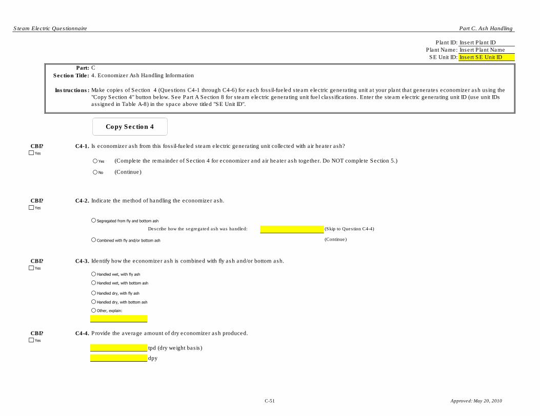
Steam Electric Questionnaire Part C. Ash Handling
Plant ID: Insert Plant ID
Plant Name: Insert Plant Name
SE Unit ID: Insert SE Unit ID
Part: C
Section Title: 4. Economizer Ash Handling Information
Instructions:
CBI? C4-1.
(Complete the remainder of Section 4 for economizer and air heater ash together. Do NOT complete Section 5.)
(Continue)
CBI? C4-2.
Describe how the segregated ash was handled: (Skip to Question C4-4)
(Continue)
CBI? C4-3. Identify how the economizer ash is combined with fly ash and/or bottom ash.
CBI? C4-4.
tpd (dry weight basis)
dpy
Make copies of Section 4 (Questions C4-1 through C4-6) for each fossil-fueled steam electric generating unit at your plant that generates economizer ash using the
"Copy Section 4" button below. See Part A Section 8 for steam electric generating unit fuel classifications. Enter the steam electric generating unit ID (use unit IDs
assigned in Table A-8) in the space above titled "SE Unit ID".
Indicate the method of handling the economizer ash.
Provide the average amount of dry economizer ash produced.
Is economizer ash from this fossil-fueled steam electric generating unit collected with air heater ash?
Yes
Segregated from fly and bottom ash
Combined with fly and/or bottom ash
Handled wet, with fly ash
Handled wet, with bottom ash
Handled dry, with fly ash
Handled dry, with bottom ash
Yes
Yes
Yes
No
Yes
Other, explain:
Copy Section 4
C-51 Approved: May 20, 2010

Steam Electric Questionnaire Part C. Ash Handling
CBI? C4-5.
(Continue)
(Skip to Section 5)
gpd Over days
CBI? C4-6.
% of economizer ash
% of economizer ash
% of economizer ash
% of economizer ash
% of economizer ash
% of economizer ash
What is the final disposition/destination of the collected economizer ash? [Check all boxes that apply.] Indicate the percentage of economizer ash transported to each
destination.
Provide the volume of economizer ash wastewater generated in 2009 (gpd) and the frequency of economizer ash wastewater generation (days).
Provide the destination of the economizer ash wastewater generated:
Is process wastewater generated from the handling of economizer ash?
Yes
Yes
No
Yes
Stored in a landfill reported in Table A-6
Stored in a landfill NOT reported in Table A-6
Stored in a pond/impoundment reported in Table A-4
Other:
Hauled off site (to be given away)
Hauled off site (to be marketed)
Destination Codes Table
C-52 Approved: May 20, 2010

Steam Electric Questionnaire Part C. Ash Handling
Plant ID: Insert Plant ID
Plant Name: Insert Plant Name
SE Unit ID: Insert SE Unit ID
Part: C
Section Title: 5. Air Heater Ash Handling Information
Instructions:
CBI? C5-1.
Describe how the segregated ash was handled: (Skip to Question C5-3)
(Continue)
CBI? C5-2. Identify how the air heater ash is combined with fly ash and/or bottom ash.
CBI? C5-3.
tpd (dry weight basis)
dpy
Make copies of Section 5 (Questions C5-1 through C5-5) for each fossil-fueled steam electric generating unit at your plant that generates air heater ash using the
"Copy Section 5" button below. See Part A Section 8 for steam electric generating unit fuel classifications. Enter the steam electric generating unit ID (use unit IDs
assigned in Table A-8) in the space above titled "SE Unit ID".
Indicate the method of handling the air heater ash.
Provide the average amount of dry air heater ash produced.
Yes
Yes
Handled wet, with fly ash
Handled wet, with bottom ash
Handled dry, with fly ash
Handled dry, with bottom ash
Yes
Other, explain:
Segregated from fly and bottom ash
Combined with fly and/or bottom ash
Copy Section 5
C-53 Approved: May 20, 2010

Steam Electric Questionnaire Part C. Ash Handling
CBI? C5-4.
(Continue)
(Skip to next Questionnaire Part)
gpd Over days
CBI? C5-5.
% of air heater ash
% of air heater ash
% of air heater ash
% of air heater ash
% of air heater ash
% of air heater ash
What is the final disposition/destination of the collected air heater ash? [Check all boxes that apply.] Indicate the percentage of air heater ash transported to each
destination.
Provide the volume of air heater ash wastewater generated in 2009 (gpd) and the frequency of air heater ash wastewater generation (days).
Is process wastewater generated from the handling of air heater ash?
Provide the destination of the air heater ash wastewater generated:
Yes
Yes
No
Yes
Stored in a landfill reported in Table A-6
Stored in a landfill NOT reported in Table A-6
Stored in a pond/impoundment reported in Table A-4
Other:
Hauled off site (to be given away)
Hauled off site (to be marketed)
Destination Codes Table
C-54 Approved: May 20, 2010

Steam Electric Questionnaire Part C. Ash Handling
Plant ID: Insert Plant ID
Plant Name: Insert Plant Name
Part: C
Section Title:
Instructions:
Question
Number
CBI?
CBI?
CBI?
CBI?
CBI?
CBI?
CBI?
CBI?
CBI?
CBI?
Part C Comments
Cross reference your comments by question number and indicate the confidential status of your comment by checking the box
next to “Yes” under "CBI?" (Confidential Business Information).
Comment
Yes
Yes
Yes
Yes
Yes
Yes
Yes
Yes
Yes
Yes
C-55 Approved: May 20, 2010

Steam Electric Questionnaire Part C. Ash Handling
CBI?
CBI?
CBI?
CBI?
CBI?
CBI?
CBI?
CBI?
CBI?
CBI?
CBI?
CBI?
CBI?
CBI?Yes
Yes
Yes
Yes
Yes
Yes
Yes
Yes
Yes
Yes
Yes
Yes
Yes
Yes
C-56 Approved: May 20, 2010

Steam Electric Questionnaire Part C. Ash Handling
Air heater cleaning water AHCW
Ash pile runoff APR Effluent - 1 EFF-1
Boiler blowdown BB Effluent - 2 EFF-2
Boiler fireside cleaning water BFCW Effluent - 3 EFF-3
Boiler tube cleaning water BTCW Effluent - 4 EFF-4
Bottom ash sluice BAS Effluent - 5 EFF-5
Carbon capture wastewater CCAPW Effluent - 6 EFF-6
Coal pile runoff CPR Filter backwash FltBW
Combined ash sluice CAS Sludge SLDG
Combustion turbine cleaning (combustion gas portion of
turbine) water
COMBCW
Combustion turbine cleaning (compressor portion of the
turbine) water
COMPRCW POND-1 Effluent POND-1-EFF
Combustion turbine evaporative coolers blowdown TECB POND-2 Effluent POND-2-EFF
Cooling tower blowdown CTB POND-3 Effluent POND-3-EFF
FGD scrubber purge SCRBP POND-4 Effluent POND-4-EFF
FGD slurry blowdown FGDB POND-5 Effluent POND-5-EFF
Filter Backwash FLTBW POND-6 Effluent POND-6-EFF
Floor drain wastewater FDW POND-7 Effluent POND-7-EFF
Flue gas mercury control system wastewater FGMCW POND-8 Effluent POND-8-EFF
Fly ash sluice FAS POND-9 Effluent POND-9-EFF
General runoff GR POND-10 Effluent POND-10-EFF
Gypsum pile runoff GPR POND-A Effluent POND-A-EFF
Gypsum wash water GYPWW POND-B Effluent POND-B-EFF
Ion exchange wastewater IXW POND-C Effluent POND-C-EFF
Landfill runoff - capped landfill LRC WWT-1 Effluent WWT-1-EFF
Landfill runoff - uncapped landfill LRUC WWT-2 Effluent WWT-2-EFF
Leachate LEACH WWT-3 Effluent WWT-3-EFF
Limestone pile runoff LPR WWT-4 Effluent WWT-4-EFF
Mill reject sluice MRS WWT-5 Effluent WWT-5-EFF
For Use as Influents to Pond/Impoundment Systems and/or
Wastewater Treatment Systems in Part D, Table D-3, AND
Recycled Waters Throughout Questionnaire.
Steam Electric Questionnaire Code Tables
Process Wastewaters Treated Wastewaters
For Use in Tables and Questions throughout Parts A, B, C, D, and F.For Use as Effluents from Pond/Impoundment Systems
and/or Wastewater Treatment Systems in Part D, Table D-4.
Approved: May 20, 2010
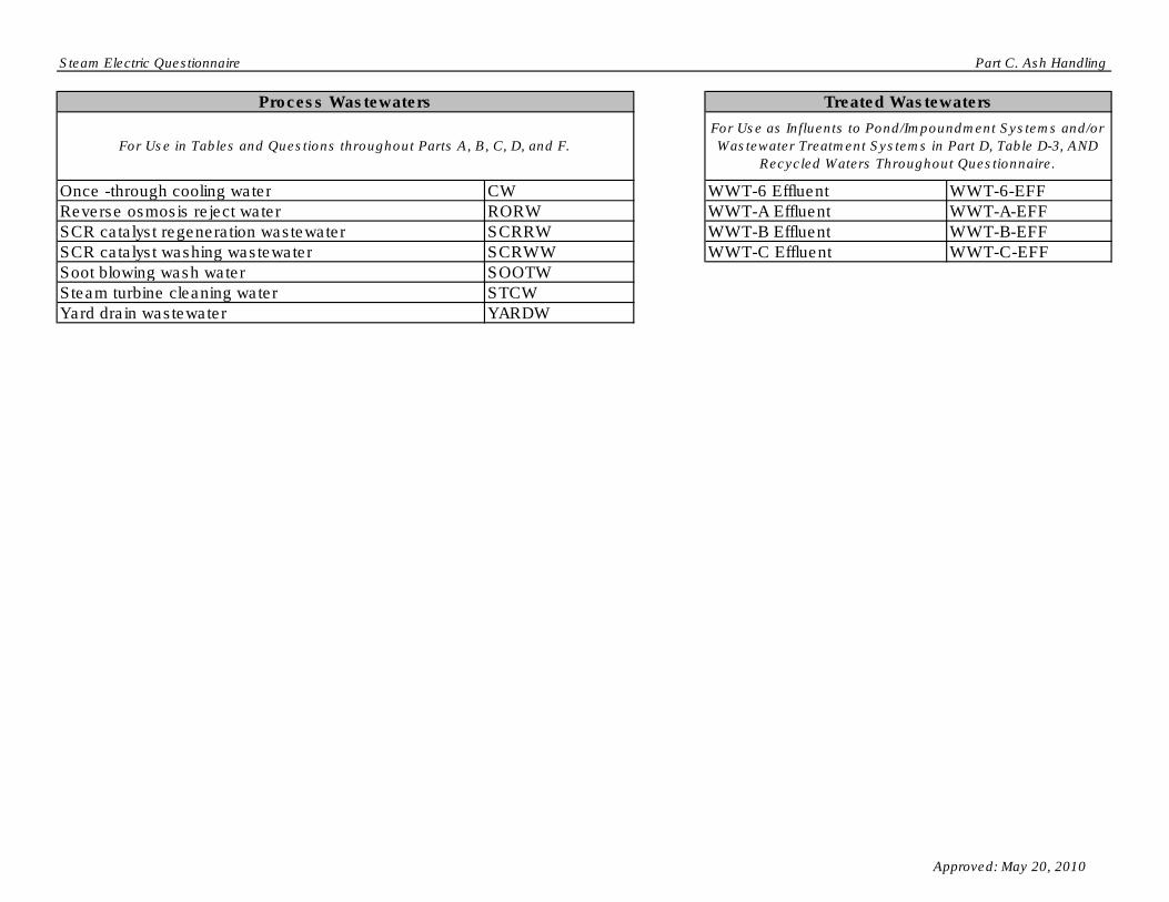
Steam Electric Questionnaire Part C. Ash Handling
Once -through cooling water CW WWT-6 Effluent WWT-6-EFF
Reverse osmosis reject water RORW WWT-A Effluent WWT-A-EFF
SCR catalyst regeneration wastewater SCRRW WWT-B Effluent WWT-B-EFF
SCR catalyst washing wastewater SCRWW WWT-C Effluent WWT-C-EFF
Soot blowing wash water SOOTW
Steam turbine cleaning water STCW
Yard drain wastewater YARDW
For Use in Tables and Questions throughout Parts A, B, C, D, and F.
For Use as Influents to Pond/Impoundment Systems and/or
Wastewater Treatment Systems in Part D, Table D-3, AND
Recycled Waters Throughout Questionnaire.
Process Wastewaters Treated Wastewaters
Approved: May 20, 2010
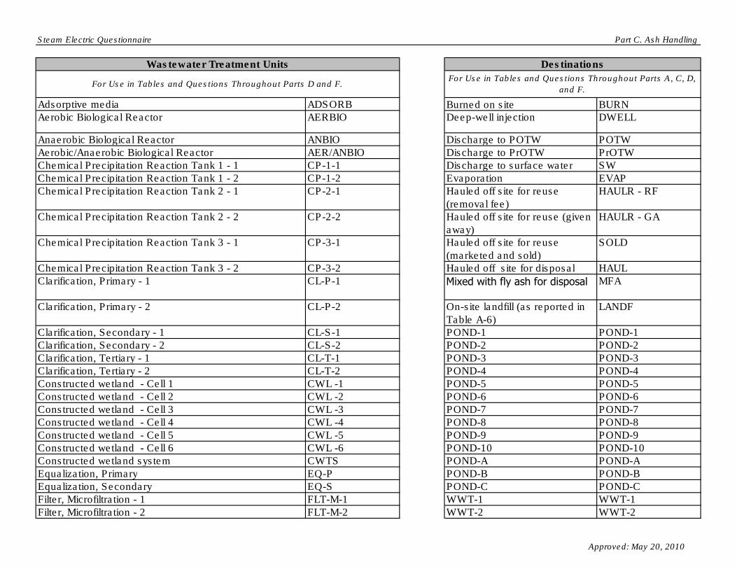
Steam Electric Questionnaire Part C. Ash Handling
Adsorptive media ADSORB Burned on site BURNAerobic Biological Reactor AERBIO Deep-well injection DWELL
Anaerobic Biological Reactor ANBIO Discharge to POTW POTW
Aerobic/Anaerobic Biological Reactor AER/ANBIO Discharge to PrOTW PrOTW
Chemical Precipitation Reaction Tank 1 - 1 CP-1-1 Discharge to surface water SW
Chemical Precipitation Reaction Tank 1 - 2 CP-1-2 Evaporation EVAP
Chemical Precipitation Reaction Tank 2 - 1 CP-2-1 Hauled off site for reuse
(removal fee)
HAULR - RF
Chemical Precipitation Reaction Tank 2 - 2 CP-2-2 Hauled off site for reuse (given
away)
HAULR - GA
Chemical Precipitation Reaction Tank 3 - 1 CP-3-1 Hauled off site for reuse
(marketed and sold)
SOLD
Chemical Precipitation Reaction Tank 3 - 2 CP-3-2 Hauled off site for disposal HAUL
Clarification, Primary - 1 CL-P-1 Mixed with fly ash for disposal MFA
Clarification, Primary - 2 CL-P-2 On-site landfill (as reported in
Table A-6)
LANDF
Clarification, Secondary - 1 CL-S-1 POND-1 POND-1
Clarification, Secondary - 2 CL-S-2 POND-2 POND-2
Clarification, Tertiary - 1 CL-T-1 POND-3 POND-3
Clarification, Tertiary - 2 CL-T-2 POND-4 POND-4
Constructed wetland - Cell 1 CWL -1 POND-5 POND-5
Constructed wetland - Cell 2 CWL -2 POND-6 POND-6
Constructed wetland - Cell 3 CWL -3 POND-7 POND-7
Constructed wetland - Cell 4 CWL -4 POND-8 POND-8
Constructed wetland - Cell 5 CWL -5 POND-9 POND-9
Constructed wetland - Cell 6 CWL -6 POND-10 POND-10
Constructed wetland system CWTS POND-A POND-A
Equalization, Primary EQ-P POND-B POND-B
Equalization, Secondary EQ-S POND-C POND-C
Filter, Microfiltration - 1 FLT-M-1 WWT-1 WWT-1
Filter, Microfiltration - 2 FLT-M-2 WWT-2 WWT-2
For Use in Tables and Questions Throughout Parts D and F.For Use in Tables and Questions Throughout Parts A, C, D,
and F.
Wastewater Treatment Units Destinations
Approved: May 20, 2010

Steam Electric Questionnaire Part C. Ash Handling
Filter, Microfiltration - 3 FLT-M-3 WWT-3 WWT-3
Filter, Microfiltration - 4 FLT-M-4 WWT-4 WWT-4
Filter, Sand/Gravity - 1 FLT-S-1 WWT-5 WWT-5
Filter, Sand/Gravity - 2 FLT-S-2 WWT-6 WWT-6
Filter, Sand/Gravity - 3 FLT-S-3 WWT-A WWT-AFilter, Sand/Gravity - 4 FLT-S-4 WWT-B WWT-B
Filter, Ultrafiltration - 1 FLT-U-1 WWT-C WWT-C
Filter, Ultrafiltration - 2 FLT-U-2 Reuse as boiler water RECYC - BW
Filter, Ultrafiltration - 3 FLT-U-3 Reuse as bottom ash sluice RECYC - BAS
Filter, Ultrafiltration - 4 FLT-U-4 Reuse as combined ash sluice RECYC - CAS
Filter press - 1 FP-1 Reuse as FGD slurry
preparation water
RECYC - FGDP
Filter press - 2 FP-2 Reuse as FGD absorber
makeup
RECYC - FGDAB
Holding tank HT Reuse as fly ash sluice RECYC - FAS
Ion exchange IX Reuse as mill reject sluice RECYC - MRS
Natural wetlands NW Reuse in cooling towers RECYC - CW
pH adjustment - 1 PH-1
pH adjustment - 2 PH-2
pH adjustment - 3 PH-3
Reverse osmosis ROS
Pond Unit - 1 SPD-1
Pond Unit - 2 SPD-2
Pond Unit - 3 SPD-3
Pond Unit - 4 SPD-4
Pond Unit - 5 SPD-5
Pond Unit - 6 SPD-6
Pond Unit - 7 SPD-7
Pond Unit - 8 SPD-8
Pond Unit - 9 SPD-9
Wastewater Treatment Units Destinations
For Use in Tables and Questions Throughout Parts D and F.For Use in Tables and Questions Throughout Parts A, C, D,
and F.
Approved: May 20, 2010

Steam Electric Questionnaire Part C. Ash Handling
Pond Unit - 10 SPD-10Centrifuge - 1 CENT-1
Pond Unit - 11 SPD-11 Centrifuge - 2 CENT-2Pond Unit - 12 SPD-12 Centrifuge - 3 CENT-3Pond Unit - 13 SPD-13 Centrifuge - 4 CENT-4Pond Unit - 14 SPD-14 Hydrocyclones - 1 HYC-1
Settling tank - 1 ST-1 Hydrocyclones - 2 HYC-2
Settling tank - 2 ST-2 Hydrocyclones - 3 HYC-3
Settling tank - 3 ST-3 Hydrocyclones - 4 HYC-4
Settling tank - 4 ST-4 Filter press - 1 FP-1
Settling tank - 5 ST-5 Filter press - 2 FP-2
Thickener - 1 TH-1 Thickener - 1 TH-1
Thickener - 2 TH-2 Thickener - 2 TH-2
Vacuum drum filter - 1 VF-1 Vacuum drum filter - 1 VF-1
Vacuum drum filter - 2 VF-2 Vacuum drum filter - 2 VF-2
Vacuum filter belt - 1 VFB-1 Vacuum filter belt - 1 VFB-1
Vacuum filter belt - 2 VFB-2 Vacuum filter belt - 2 VFB-2
Solids Handling
For Use as Planned Solids Handling for the FGD Slurry
Blowdown in Part B Table B-2.
Wastewater Treatment Units
For Use in Tables and Questions Throughout Parts D and F.
Approved: May 20, 2010
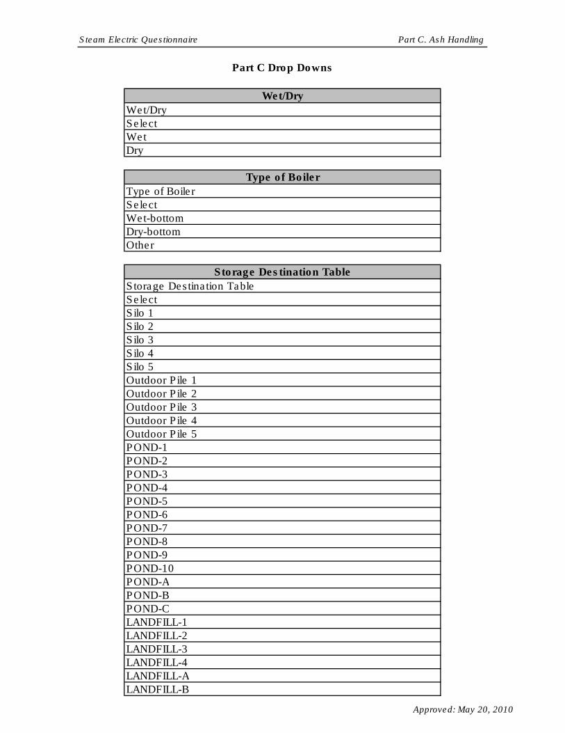
Steam Electric Questionnaire Part C. Ash Handling
Part C Drop Downs
Wet/Dry
Wet/Dry
Select
Wet
Dry
Type of Boiler
Type of Boiler
Select
Wet-bottom
Dry-bottom
Other
Storage Destination Table
Storage Destination Table
Select
Silo 1
Silo 2
Silo 3
Silo 4
Silo 5
Outdoor Pile 1
Outdoor Pile 2
Outdoor Pile 3
Outdoor Pile 4
Outdoor Pile 5
POND-1
POND-2
POND-3
POND-4
POND-5
POND-6
POND-7
POND-8
POND-9
POND-10
POND-A
POND-B
POND-C
LANDFILL-1
LANDFILL-2
LANDFILL-3
LANDFILL-4
LANDFILL-A
LANDFILL-B
Approved: May 20, 2010

Steam Electric Questionnaire Part C. Ash Handling
LANDFILL-C
LANDFILL-D
Marketed, sold or given away
Stored in landfills NOT reported in Table A-6
Other
Destination Codes Table
Destination Codes Table
Select
Burned on site
Deep-well injection
Discharge to POTW
Discharge to PrOTW
Discharge to surface water
Evaporation
Hauled off site for reuse (removal fee)
Hauled off site for reuse (given away)
Hauled off site for reuse (marketed and sold)
Hauled off site for disposal
Mixed with fly ash for disposalOn-site landfill (as reported in Table A-6)
POND-1
POND-2
POND-3
POND-4
POND-5
POND-6
POND-7
POND-8
POND-9
POND-10
POND-A
POND-B
POND-C
WWT-1
WWT-2
WWT-3
WWT-4
WWT-5
WWT-6
WWT-A
WWT-B
WWT-C
Reuse as boiler water
Reuse as bottom ash sluice
Reuse as combined ash sluice
Reuse as FGD slurry preparation water
Approved: May 20, 2010

Steam Electric Questionnaire Part C. Ash Handling
Reuse as FGD absorber makeup
Reuse as fly ash sluice
Reuse as mill reject sluice
Reuse in cooling towers
Sluice Water Source
Sluice Water Source
Select
IN
IN-Makeup
TR
TR-Makeup
Air heater cleaning water
Ash pile runoff
Boiler blowdown
Boiler fireside cleaning water
Boiler tube cleaning water
Bottom ash sluice
Carbon capture wastewater
Coal pile runoff
Combined ash sluice
Combustion turbine cleaning (combustion gas portion of
turbine) waterCombustion turbine cleaning (compressor portion of the
turbine) waterCombustion turbine evaporative coolers blowdown
Cooling tower blowdown
FGD scrubber purge
FGD slurry blowdown
Filter Backwash
Floor drain wastewater
Flue gas mercury control system wastewater
Fly ash sluice
General runoff
Gypsum pile runoff
Gypsum wash water
Ion exchange wastewater
Landfill runoff - capped landfill
Landfill runoff - uncapped landfill
Leachate
Limestone pile runoff
Mill reject sluice
Once -through cooling water
Reverse osmosis reject water
SCR catalyst regeneration wastewater
SCR catalyst washing wastewater
Soot blowing wash water
Approved: May 20, 2010

Steam Electric Questionnaire Part C. Ash Handling
Steam turbine cleaning water
Yard drain wastewater
POND-1 Effluent
POND-2 Effluent
POND-3 Effluent
POND-4 Effluent
POND-5 Effluent
POND-6 Effluent
POND-7 Effluent
POND-8 Effluent
POND-9 Effluent
POND-10 Effluent
POND-A Effluent
POND-B Effluent
POND-C Effluent
WWT-1 Effluent
WWT-2 Effluent
WWT-3 Effluent
WWT-4 Effluent
WWT-5 Effluent
WWT-6 Effluent
WWT-A Effluent
WWT-B Effluent
WWT-C Effluent
Process Wastewaters
Process Wastewaters
Select
Air heater cleaning water
Ash pile runoff
Boiler blowdown
Boiler fireside cleaning water
Boiler tube cleaning water
Bottom ash sluice
Carbon capture wastewater
Coal pile runoff
Combined ash sluice
Combustion turbine cleaning (combustion gas portion of
turbine) waterCombustion turbine cleaning (compressor portion of the
turbine) waterCombustion turbine evaporative coolers blowdown
Cooling tower blowdown
FGD scrubber purge
FGD slurry blowdown
Filter Backwash
Floor drain wastewater
Approved: May 20, 2010

Steam Electric Questionnaire Part C. Ash Handling
Flue gas mercury control system wastewater
Fly ash sluice
General runoff
Gypsum pile runoff
Gypsum wash water
Ion exchange wastewater
Landfill runoff - capped landfill
Landfill runoff - uncapped landfill
Leachate
Limestone pile runoff
Mill reject sluice
Once -through cooling water
Reverse osmosis reject water
SCR catalyst regeneration wastewater
SCR catalyst washing wastewater
Soot blowing wash water
Steam turbine cleaning water
Yard drain wastewater
Other
Fly Ash Conveyance Components
Fly Ash Conveyance Components
Select
Conveyor
Dewatering bin
Pressure blower
Transfer hopper
Wet vacuum equipment (e.g., hydroveyor)
Other
Fly Ash Intermediate Storage Components
Fly Ash Intermediate Storage Components
Select
Conveyor system (e.g., air slide, bucket conveyor)
Loading silo
Pug mill/pin mixer
Storage silo
Other
Bottom Ash Conveyance Components
Bottom Ash Conveyance Components
Select
Clarifying tank
Conveyor
Dewatering bin
Surge tank
Approved: May 20, 2010

Steam Electric Questionnaire Part C. Ash Handling
Wet vacuum equipment (e.g., hydroveyor)
Other
Bottom Ash Intermediate Storage Components
Bottom Ash Intermediate Storage Components
Select
Conveyor system (e.g., air slide, bucket conveyor)
Loading silo
Pug mill/pin mixer
Storage silo
Other
Market Destinations
Market Destinations
Select
Aggregate
Agriculture
Blasting Grit/Roofing Granules
Blended Cement/Raw Feed for Clinker
Concrete/Concrete Products/Grout
Flowable Fill
Mineral Filler in Asphalt
Mining Applications
Road Base/Sub-base
Snow and Ice Control
Soil Modification/Stabilization
Structural Fills/Embankments
Waste Stabilization/Solidification
Other
Units
Units
Select
gpd
gpy
Component Units
Component Units
Select
gal
hp
in
Other
Combined Intermediate Storage Components
Combined Intermediate Storage Components
Approved: May 20, 2010

Steam Electric Questionnaire Part C. Ash Handling
Select
Air slide
Baghouse for silos
Bin vent filter
Bucket conveyor
Conditioned load out spout with dust collection system
Conveyor system
Dust suppression (e.g., water truck)
Dry load out spout
Loading silo
Pug mill/pin mixer
Stackout/holding areas
Storage bin
Storage hopper
Storage silo
Vacuum loading equipment
Other
Approved: May 20, 2010

OMB Control Number: 2040-0281 Plant ID: Insert Plant ID
Approval Expires: 05/31/2013 Plant Name: Insert Plant Name
Section Title Tab Name
Part D Instructions Part D Instructions
Part D Section 1
Part D Section 2
Wastewater Treatment Diagram Part D Section 3.1
Wastewater Treatment Wastewater Flows Part D Section 3.2
Part D Section 4.1
Closed Pond/Impoundment Unit Information Part D Section 4.2
Wastewater Treatment Unit Information - System Level Part D Section 5.1
Wastewater Treatment System Chemical Addition Part D Section 5.2
Part D Section 6.1
Part D Section 6.2
Part D Comments Part D Comments
Steam Electric Questionnaire Code Tables Code Tables
Pond/Impoundment System and Wastewater
Treatment System Equipment
Plant Pond/Impoundment Systems and Wastewater
Treatment Systems
Pond/Impoundment System and Wastewater
Treatment System Identification
Steam Electric Questionnaire
PART D - POND/IMPOUNDMENT SYSTEMS AND OTHER WASTEWATER TREATMENT
OPERATIONS
Table of Contents
Active/Inactive/Open and Planned
Pond/Impoundment Unit Information
Pond/Impoundment System and Wastewater
Treatment System Costs
Approved: May 20, 2010

Steam Electric Questionnaire Part D. Instructions
Plant ID: Insert Plant ID
Plant Name: Insert Plant Name
PART D.
A “wastewater treatment unit ” is defined as a unit operation used to remove pollutants
from process wastewater. Wastewater treatment units include, but are not limited to:
ponds/impoundments, chemical precipitation, pH adjustment, clarification, biological
reactor, thickeners, filters, and constructed wetlands.
NOTE: If a pond/impoundment unit (as defined in Section 4.1) is part of a broader
“wastewater treatment system” containing non-pond units (e.g., a
pond/impoundment unit in a biological wastewater treatment system), it is not
considered part of a pond/impoundment system.
A "pond/impoundment" is defined as a natural topographic depression, man-made
excavation, or diked area formed from earthen materials or man-made materials or a
combination of them, which is designed to hold an accumulation of liquid process
wastes or process wastes containing free liquids, and which is not an injection well.
Examples of ponds/impoundments include holding, storage, settling, and aeration pits,
ponds, and lagoons. It does not include building sumps and outdoor collection/transfer
concrete basins.
A “pond/impoundment system ” is defined as a system consisting of one or more
ponds/impoundments.
A “wastewater treatment system ” is defined as a combination of one or more
“wastewater treatment units”, other than ponds/impoundments, designed to achieve
wastewater treatment.
POND/IMPOUNDMENT SYSTEMS AND OTHER WASTEWATER
TREATMENT OPERATIONS
INSTRUCTIONS
Part D requests information about all ponds/impoundments used (or planned to be used
or under construction/installation by December 31, 2020) for the storage, treatment,
and/or disposal of process wastewater, residues, or by-products (or sludges or water
streams containing the residues or by-products) from the combustion of coal, petroleum
coke, or oil, including but not limited to fly ash, bottom ash, boiler slag, or flue gas
emission control residues. Additionally, Part D requests information about wastewater
treatment systems, other than pond/impoundment systems, for the treatment of
wastewaters from ash handling or FGD operations that are located at the plant or are
planned to be located at the plant. Complete Part D if you operate one or more systems,
or if you are currently constructing/installing, or planning to construct/install one or more
systems by December 31, 2020.
Refer to the following definitions throughout Part D.
Approved: May 20, 2010

Steam Electric Questionnaire Part D. Instructions
Use the Part D Comments tab to do the following: provide additional information as
requested in certain questions within Part D; indicate atypical data (e.g., if 2009
information is not representative of normal operations); and note methods used to make
best engineering estimates in the event that exact data are not available.
Throughout Part D, information is requested for pond/impoundment and wastewater
treatment units and systems that are under construction/installation, or planned to be
under construction/installation by December 31, 2020. Provide design information, or
best engineering estimates as necessary, for these planned systems/units. Additionally,
indicate “NA” if the information requested is not applicable for planned systems/units
(e.g., a question that requests flow rate data for year 2009).
As you are completing the electronic form, note the following: When you enter your plant
name and plant ID on the Part D Table of Contents tab, all name and ID fields
throughout Part D will automatically populate. Refer to the overall questionnaire
instructions, the glossary, and the acronym list for assistance with completing Part D.
Please provide all free response answers in the highlighted yellow areas. Throughout
Part D, you may need to make copies of certain sections/questions. Instructions are
provided throughout Part D regarding making copies. Note that pond/impoundment
system (and unit) and wastewater treatment system ID's must be populated on the
copied tab or section, located in the upper right corner under "Plant ID" and "Plant
Name", in order to correlate the requested information with the pond/impoundment or
wastewater treatment system.
Approved: May 20, 2010

Steam Electric Questionnaire Part D. Pond/Impoundment Systems and Other Wastewater Treatment Operations
Plant ID: Insert Plant ID
Plant Name: Insert Plant Name
Part: D
Section Title:
CBI? D1-1.
CBI? D1-2.
If you answered "No" to both Questions D1-1 and D1-2, do NOT complete the remainder of
Part D. Skip to the next Questionnaire Part. Otherwise, continue to Part D Section 2.
1. Plant Pond/Impoundment Systems and Wastewater Treatment Systems
Do you operate OR plan to operate (or begin construction/installation of) by December 31, 2020 any wastewater treatment systems, other than
pond/impoundment systems, for the treatment of process wastewaters from ash handling or FGD operations?
Have you used, do you use, OR do you plan to use (or begin construction/installation of) by December 31, 2020 any ponds/impoundments for the
storage, treatment, and/or disposal of process wastewater , residues , or by-products (or sludges or water streams containing the residues or by-
products) from the combustion of coal, petroleum coke, or oil, including but not limited to fly ash , bottom ash , boiler slag, or flue gas emission control
residues?
Note: This includes systems located on non-adjoining property that are under the operational control of the plant.
Note: This includes ponds/impoundments located on non-adjoining property that are under the operational control of the plant.
Yes
Yes
No
Yes
Yes
No
D-1 Approved: May 20, 2010

Steam Electric Questionnaire Part D. Pond/Impoundment Systems and Other Wastewater Treatment Operations
Plant ID: Insert Plant ID
Plant Name: Insert Plant Name
Part: D
Section Title:
Instructions:
CBI? D2-1.
(Continue)
CBI? D2-2.
CBI? D2-3.
(Provide a copy of the summary/report)
(Continue)
Provide a description of the pilot- or full-scale study. Note the types of treatment technologies studied and the analytes measured in influent to and/or effluents from the
wastewater treatment system.
(Skip to Question D2-4)
2. Pond/Impoundment System and Wastewater Treatment System Identification
Complete Section 2 (Questions D2-1 through D2-7) for pond/impoundment systems and/or wastewater treatment systems that the plant operates and/or plans to operate
(or begin construction/installation of) by December 31, 2020, including those located on non-adjoining property, for the treatment of process wastewaters from ash
handling or FGD operations. Please provide all free response answers in the highlighted yellow areas.
Has the plant been involved with any ash or FGD wastewater treatment studies (pilot- or full-scale), including studies on pond/impoundment systems, since 2000?
Are any of these studies ongoing?
Was a summary and/or report describing/documenting the pilot- or full-scale study prepared (including internal and published reports)?
Yes
Yes
Yes
Yes
Yes
No
Yes
No
No
D-2 Approved: May 20, 2010

Steam Electric Questionnaire Part D. Pond/Impoundment Systems and Other Wastewater Treatment Operations
CBI? D2-4.
CBI? D2-5.
(Continue)
CBI? D2-6.
(Continue)
NOTE: Do NOT include a pond/impoundment unit in Table D-1 if the pond/impoundment unit is or is planned to be part of a broader wastewater treatment
system containing non-pond wastewater treatment units (e.g., pond/impoundment unit in a biological wastewater treatment system).
(Skip to Section 4.1)
List any ash or FGD wastewater treatment technologies that have been studied by the plant that are not covered by Questions D2-1 through D2-3 (e.g., those that have
been studied in bench-scale studies).
List these pond/impoundment systems in Table D-1. For each pond/impoundment system, EPA assigned a number (e.g., POND-1, POND-2) in Table D-1, which will be
used throughout the remainder of the survey. In the "Plant Designation" column, provide the plant's name for each pond/impoundment system. In the "Individual
Ponds/Impoundments Included in the Pond System" column, identify all pond/impoundment units from Table A-4 that are included in the pond system.
Do you operate OR plan to operate (or begin construction/installation of) by December 31, 2020 any pond/impoundment systems, including those located on non-
adjoining property, for the treatment of process wastewaters from ash handling or FGD operations?
Do you operate OR plan to operate (or begin construction/installation of) by December 31, 2020 any systems, including those located on non-adjoining property, for the
treatment of process wastewaters from ash handling or FGD operations?
(Skip to Question D2-7)
Yes
Yes
No
Yes
Yes
No
Yes
Yes
D-3 Approved: May 20, 2010

Steam Electric Questionnaire Part D. Pond/Impoundment Systems and Other Wastewater Treatment Operations
Pond/ Impoundment
System ID
Year Initially Brought
Online Plant Designation
POND-1
POND-2
POND-3
POND-4
POND-5
POND-6
POND-7
POND-8
POND-9
POND-10
Table D-1. Plant Pond/Impoundment Systems
Active/Inactive/Open Pond/Impoundment Systems
Individual Pond/Impoundments (Identified in Table A-4) Included in the
Pond/Impoundment System
SPD - 1 SPD - 3 SPD - 5
SPD - 6
SPD - 7
SPD - 8
SPD - 9
SPD - 2 SPD - 4 SPD - 10
SPD - 11
SPD - 12
SPD - 13
SPD - 14
SPD - 1 SPD - 3 SPD - 5
SPD - 6
SPD - 7
SPD - 8
SPD - 9
SPD - 2 SPD - 4 SPD - 10
SPD - 11
SPD - 12
SPD - 13
SPD - 14
SPD - 1 SPD - 3 SPD - 5
SPD - 6
SPD - 7
SPD - 8
SPD - 9
SPD - 2 SPD - 4 SPD - 10
SPD - 11
SPD - 12
SPD - 13
SPD - 14
SPD - 1 SPD - 3 SPD - 5
SPD - 6
SPD - 7
SPD - 8
SPD - 9
SPD - 2 SPD - 4 SPD - 10
SPD - 11
SPD - 12
SPD - 13
SPD - 14
SPD - 1 SPD - 3 SPD - 5
SPD - 6
SPD - 7
SPD - 8
SPD - 9
SPD - 2 SPD - 4 SPD - 10
SPD - 11
SPD - 12
SPD - 13
SPD - 14
SPD - 1 SPD - 3 SPD - 5
SPD - 6
SPD - 7
SPD - 8
SPD - 9
SPD - 2 SPD - 4 SPD - 10
SPD - 11
SPD - 12
SPD - 13
SPD - 14
SPD - 1 SPD - 3 SPD - 5
SPD - 6
SPD - 7
SPD - 8
SPD - 9
SPD - 2 SPD - 4 SPD - 10
SPD - 11
SPD - 12
SPD - 13
SPD - 14
SPD - 1 SPD - 3 SPD - 5
SPD - 6
SPD - 7
SPD - 8
SPD - 9
SPD - 2 SPD - 4 SPD - 10
SPD - 11
SPD - 12
SPD - 13
SPD - 14
SPD - 1 SPD - 3 SPD - 5
SPD - 6
SPD - 7
SPD - 8
SPD - 9
SPD - 2 SPD - 4 SPD - 10
SPD - 11
SPD - 12
SPD - 13
SPD - 14
SPD - 1 SPD - 3 SPD - 5
SPD - 6
SPD - 7
SPD - 8
SPD - 9
SPD - 2 SPD - 4 SPD - 10
SPD - 11
SPD - 12
SPD - 13
SPD - 14
D-4 Approved: May 20, 2010

Steam Electric Questionnaire Part D. Pond/Impoundment Systems and Other Wastewater Treatment Operations
RET-POND-1
RET-POND-2
RET-POND-3
RET-POND-4
RET-POND-5
POND-A
POND-B
POND-C
CBI? D2-7.
(Continue)
Do you operate OR plan to operate (or begin construction/installation of) by December 31, 2020 any wastewater treatment systems, including those located on non-
adjoining property, other than pond/impoundment systems for the treatment of process wastewaters from ash handling or FGD operations?
List these wastewater treatment systems in Table D-2. For each wastewater treatment system, EPA assigned a number (e.g., WWT-1, WWT-2) in Table D-2, which will
be used throughout the remainder of the survey. In the “Plant Designation” column, provide the plant’s name for each wastewater treatment system. As an example, if a
plant operates a chemical precipitation FGD wastewater treatment system that discharges to an ash pond/impoundment system (as shown in EPA example diagrams
EPA_D-1 and EPA_D-2 located at the bottom of Part D Section 3.1) the FGD wastewater treatment system should be identified in Table D-2 (e.g., as WWT-1) and the
ash pond/impoundment system should have been previously identified in Table D-1 (e.g., as POND-1).
(Skip to Section 3.1)
Retired/Closed Pond/Impoundment Systems
Note that "Approximate Length of Piping from FGD Scrubber System" refers to the length of piping from the FGD solids separation overflow storage tank (or FGD
scrubber absorber if no FGD solids separation) to the beginning of the FGD wastewater treatment system. "Approximate Length of Piping to Subsequent Treatment or
Discharge" refers to the length of piping from the end of the FGD wastewater treatment system to either the beginning of the subsequent treatment system or the
wastewater discharge point,
as appropriate.
Planned Pond/Impoundment Systems
Yes
Yes
No
RET SPD - 1 RET SPD - 3
RET SPD - 2 RET SPD - 4
RET SPD - 1 RET SPD - 3
RET SPD - 2 RET SPD - 4
RET SPD - 1 RET SPD - 3
RET SPD - 2 RET SPD - 4
RET SPD - 1 RET SPD - 3
RET SPD - 2 RET SPD - 4
RET SPD - 1 RET SPD - 3
RET SPD - 2 RET SPD - 4
SPD - A SPD - C SPD - E
SPD - B SPD - D
SPD - A SPD - C SPD - E
SPD - B SPD - D
SPD - A SPD - C SPD - E
SPD - B SPD - D
D-5 Approved: May 20, 2010

Steam Electric Questionnaire Part D. Pond/Impoundment Systems and Other Wastewater Treatment Operations
Approximate
Length of Piping
from FGD
Scrubber System
(ft)
Approximate
Length of Piping
to Subsequent
Treatment or
Discharge (ft)
WWT-1
WWT-2
WWT-3
WWT-4
WWT-5
WWT-6
WWT-A
WWT-B
WWT-C
Operating Wastewater Treatment Systems
Planned Wastewater Treatment Systems
Table D-2. Plant Wastewater Treatment Systems
Treatment System Footprint
(ft2)Plant Designation
FGD Wastewater Treatment
Year Initially Brought On
Line
Wastewater
Treatment System ID
D-6 Approved: May 20, 2010

Steam Electric Questionnaire Part D. Pond/Impoundment Systems and Other Wastewater Treatment Operations
Plant ID: Insert Plant ID
Plant Name: Insert Plant Name
Pond/Impoundment System ID or Wastewater Treatment System ID: Insert System ID
Part: D
Section Title: 3.1. Wastewater Treatment Diagram
Instructions:
CBI? D3-1.
Complete Section 3.1 (Question D3-1) for each pond/impoundment system or wastewater treatment system identified in Table D-1
and Table D-2, including planned systems, systems under construction/installation, or planned to be under construction/installation by
December 31, 2020. Enter the pond/impoundment system ID or wastewater treatment system ID in the yellow highlighted space
provided above (use the pond/impoundment system ID or wastewater treatment system ID assigned in Table D-1 and Table D-2).
Make a copy of Section 3.1 for each pond/impoundment system or wastewater treatment system identified in Table D-1 and Table D-2
using the "Copy Section 3.1" button below.
Attach a block diagram that shows the pond/impoundment system or wastewater treatment system operations, the process
wastewaters that currently enter or are planned to enter the pond/impoundment system or wastewater treatment system, and the
ultimate destinations of the pond/impoundment system or wastewater treatment system effluent(s). Specific instructions for the
diagram are provided in the checklist below. The diagram should have a similar level of detail as EPA’s example diagrams, EPA_D-1
and EPA_D-2.
NOTE: You may use an existing diagram, such as a water balance diagram included in the plant’s NPDES Form 2C, and mark
the additional required information on the diagram by hand.
Provide as many diagrams as necessary to convey the information requested in the checklist below. Number each block diagram in
the upper right corner; the first block diagram should be numbered D-1, the second D-2, etc. Include the plant name, plant ID, and
pond/impoundment system ID or wastewater treatment system ID in the upper right hand corner of the diagram.
Diagram attached.
Copy Section 3.1
Yes
D-7 Approved: May 20, 2010
Steam Electric Questionnaire Part D. Pond/Impoundment Systems and Other Wastewater Treatment Operations
Mark the boxes below to verify that you have completed each checklist item…
Identify the final, general destination of the treated process wastewater and waste streams (e.g., treated process wastewater
effluent to POTW or surface waters; solid wastes to on- or off-site destinations). Use codes from code tables on the "Code
Tables" tab provided at the end of this workbook, when applicable.
Indicate, as appropriate, where treated process wastewater is reused or recycled within the plant (e.g., reuse of settling
pond/impoundment water as fly ash sluice).
Include the average annual (2009) flow rates for influent and effluent streams from the wastewater treatment system on the
diagram (in gpm or gpd). For planned pond/impoundment systems and wastewater treatment systems, provide the design flow
rates for the system. Note that these should be the same flow rates that are entered into Tables D-3 and D-4 in Questions D3-2
and D3-3. If the actual number of days of operation for 2009 is not known, the total annual flow may be divided by 365 days and
a comment added to the Comments page. If the process wastewater stream is intermittent, provide amount and frequency; for
example “100 gal, twice/day, 100 dpy” or “1000 gpm, 4 hpd, 365 dpy”. For sludges, provide amount in tpd.
Include NPDES permit outfall numbers, if applicable.
Indicate where chemical addition occurs (i.e., into or between which wastewater treatment units). For pond/impoundment
wastewater treatment units, indicate and note on the diagram where within or near the pond/impoundment the chemical is
added (e.g., within the pond/impoundment near the process wastewater influent point, within the pond/impoundment near the
effluent, in the effluent/discharge canal). The chemicals indicated should correspond to the chemicals listed in Table D-7 and
Table D-13.
Block Diagram Checklist
Include the block diagram number, plant name, plant ID, and pond/impoundment system ID or wastewater treatment system ID
on the diagram.
Include each pond/impoundment or wastewater treatment unit operation. Show all influent and effluent streams from the units
and label all influent and effluent streams from the pond/impoundment system or wastewater treatment system using the code
tables on the "Code Tables" tab provided at the end of this workbook. Note that the "Code Tables" tab provides codes for
wastewater treatment units that are operated in series and/or in parallel (e.g., in EPA_D-1, Chemical Precipitation Reaction
Tank 1-1 and Chemical Precipitation Reaction Tank 2-1 are in series). Effluent streams may include process wastewater and
sludges .
If applicable, use EPA-assigned numbers from Part A or B (e.g., FGD-1) to label process operations . If a process operation
does not have an EPA-assigned number (e.g., boiler, air preheater), use the plant-designated name for the process operation.
When sources or destinations are not shown on the diagram (i.e., the stream is entering from a location not shown on the
diagram), describe the source or destination and add the block diagram number, when appropriate, where the stream's previous
location can be seen. Use codes from the code tables on the "Code Tables" tab provided at the end of this workbook.
D-8 Approved: May 20, 2010

Steam Electric Questionnaire Part D. Pond/Impoundment Systems and Other Wastewater Treatment Operations
Example EPA_D-1. Block Diagram for FGD Wastewater Treatment System
If you believe that the diagram should be treated as confidential, stamp it "Confidential" or write "Confidential" or "CBI" across the top. If
any diagram is not marked "Confidential", it will be considered nonconfidential under 40 CFR Part 2, Subpart B.
If any of the statements above were not checked, revise the block diagram(s) and ensure all statements have been checked.
Review:
D-9 Approved: May 20, 2010

Steam Electric Questionnaire Part D. Pond/Impoundment Systems and Other Wastewater Treatment Operations
NOTE: The codes used in these diagrams correspond the code tables on the "Code Tables" tab provided at the end of this
workbook.
Example EPA_D-2. Block Diagram for Ash Pond System
D-10 Approved: May 20, 2010

Steam Electric Questionnaire Part D. Pond/Impoundment Systems and Other Wastewater Treatment Operations
Plant ID: Insert Plant ID
Plant Name: Insert Plant Name
Pond/Impoundment System ID or Wastewater Treatment System ID: Insert System ID
Part: D
Section Title: 3.2. Wastewater Treatment Wastewater Flows
Instructions:
CBI? D3-2.
200 gpm 10 hpd 365 dpy
Other: OR gpd dpy Other:
175 gpm 24 hpd 365 dpy
Other: OR gpd dpy Other:
gpm hpd dpy
Other: OR gpd dpy Other:
gpm hpd dpyOther: OR gpd dpy Other:
gpm hpd dpyOther: OR gpd dpy Other:
gpm hpd dpyOther: OR gpd dpy Other:
gpm hpd dpyOther: OR gpd dpy Other:
gpm hpd dpyOther: OR gpd dpy Other:
gpm hpd dpyOther: OR gpd dpy Other:
gpm hpd dpyOther: OR gpd dpy Other:
Wastewater Treatment Unit ID
Complete Section 3.2 (Question D3-2 and D3-3) for each pond/impoundment system or wastewater treatment system identified in Table D-1 and Table D-2, including planned systems, systems under construction/installation,
or planned to be under construction/installation by December 31, 2020. Enter the pond/impoundment system ID or wastewater treatment system ID in the yellow highlighted space provided above (use the pond/impoundment
system ID or wastewater treatment system ID assigned in Table D-1 and Table D-2).
Make a copy of Section 3.2 for each pond/impoundment system or wastewater treatment system identified in Table D-1 and Table D-2 using the "Copy Section 3.2" button below.
Complete a row in Table D-3 for each process wastewater stream or treated wastewater stream that enters this pond/impoundment system or wastewater treatment system. For planned pond/impoundment systems and
wastewater treatment systems, provide the design flow rates for the system. Use the process and treated wastewater terms provided in the drop down menus. Note that these terms originated from code tables on the "Code
Tables" tab provided at the end of this workbook.
Note: The examples in Tables D-3 and D-4 are derived from the EPA examples diagrams, EPA_D-1 and EPA_D-2, provided at the bottom of Part D Section 3.1.
Table D-3. Pond/Impoundment System or Wastewater Treatment System Influent Flows in 2009
Average Annual (2009) Wastewater Flow RateProcess or Treated Wastewater
Example (from EPA_D-1):
Example (from EPA_D-2):
Yes
FGD scrubber purge
WWT-1 Effluent
Copy Section 3.2
Equalization, Primary
Pond Unit - 1
Wastewater Treatment Units
Process or Treated Wastewater (Influent Table D-3)
Process or Treated Wastewater (Influent Table D-3)
Process or Treated Wastewater (Influent Table D-3)
Process or Treated Wastewater (Influent Table D-3)
Process or Treated Wastewater (Influent Table D-3)
Process or Treated Wastewater (Influent Table D-3)
Process or Treated Wastewater (Influent Table D-3)
Process or Treated Wastewater (Influent Table D-3)
Wastewater Treatment Units
Wastewater Treatment Units
Wastewater Treatment Units
Wastewater Treatment Units
Wastewater Treatment Units
Wastewater Treatment Units
Wastewater Treatment Units
D-11 Approved: May 20, 2010

Steam Electric Questionnaire Part D. Pond/Impoundment Systems and Other Wastewater Treatment Operations
gpm hpd dpyOther: OR gpd dpy Other:
gpm hpd dpyOther: OR gpd dpy Other:
gpm hpd dpyOther: OR gpd dpy Other:
gpm hpd dpyOther: OR gpd dpy Other:
gpm hpd dpyOther: OR gpd dpy Other:
gpm hpd dpyOther: OR gpd dpy Other:
gpm hpd dpyOther: OR gpd dpy Other:
gpm hpd dpyOther: OR gpd dpy Other:
gpm hpd dpyOther: OR gpd dpy Other:
gpm hpd dpyOther: OR gpd dpy Other:
gpm hpd dpyOther: OR gpd dpy Other:
gpm hpd dpyOther: OR gpd dpy Other:
gpm hpd dpyOther: OR gpd dpy Other:
gpm hpd dpyOther: OR gpd dpy Other:
gpm hpd dpyOther: OR gpd dpy Other:
gpm hpd dpyOther: OR gpd dpy Other:
gpm hpd dpyOther: OR gpd dpy Other:
gpm hpd dpyOther: OR gpd dpy Other:
gpm hpd dpyOther: OR gpd dpy Other:
gpm hpd dpyOther: OR gpd dpy Other:
gpm hpd dpyOther: OR gpd dpy Other:
gpm hpd dpyOther: OR gpd dpy Other:
Process or Treated Wastewater (Influent Table D-3)
Process or Treated Wastewater (Influent Table D-3)
Process or Treated Wastewater (Influent Table D-3)
Process or Treated Wastewater (Influent Table D-3)
Process or Treated Wastewater (Influent Table D-3)
Process or Treated Wastewater (Influent Table D-3)
Process or Treated Wastewater (Influent Table D-3)
Process or Treated Wastewater (Influent Table D-3)
Process or Treated Wastewater (Influent Table D-3)
Process or Treated Wastewater (Influent Table D-3)
Process or Treated Wastewater (Influent Table D-3)
Process or Treated Wastewater (Influent Table D-3)
Process or Treated Wastewater (Influent Table D-3)
Process or Treated Wastewater (Influent Table D-3)
Process or Treated Wastewater (Influent Table D-3)
Process or Treated Wastewater (Influent Table D-3)
Process or Treated Wastewater (Influent Table D-3)
Process or Treated Wastewater (Influent Table D-3)
Process or Treated Wastewater (Influent Table D-3)
Process or Treated Wastewater (Influent Table D-3)
Process or Treated Wastewater (Influent Table D-3)
Process or Treated Wastewater (Influent Table D-3)
Wastewater Treatment Units
Wastewater Treatment Units
Wastewater Treatment Units
Wastewater Treatment Units
Wastewater Treatment Units
Wastewater Treatment Units
Wastewater Treatment Units
Wastewater Treatment Units
Wastewater Treatment Units
Wastewater Treatment Units
Wastewater Treatment Units
Wastewater Treatment Units
Wastewater Treatment Units
Wastewater Treatment Units
Wastewater Treatment Units
Wastewater Treatment Units
Wastewater Treatment Units
Wastewater Treatment Units
Wastewater Treatment Units
Wastewater Treatment Units
Wastewater Treatment Units
Wastewater Treatment Units
D-12 Approved: May 20, 2010

Steam Electric Questionnaire Part D. Pond/Impoundment Systems and Other Wastewater Treatment Operations
CBI? D3-3.
*Provide the NPDES permit outfall number of the effluent in the last column of the table, if applicable.
% Moisture
NPDES Permit
Outfall Number*
Example (from EPA_D-1):
175 gpm 24 hpd 365 dpy NA NA NA
Other: OR NA gpd NA dpy Other: Other:
Example (from EPA_D-1):
NA gpm NA hpd NA dpy NA NA NA
Other: OR 10,000 gpd 365 dpy Other: Other:
Example (from EPA_D-2):
NA gpm NA hpd NA dpy 500 30 NA
Other: OR NA gpd NA dpy Other: Other:
Example (from EPA_D-2):
5,000 gpm 24 hpd 365 dpy NA NA NA
Other: OR NA gpd NA dpy Other: Other:
Example (from EPA_D-2):
1,175 gpm 24 hpd 365 dpy NA NA 001
Other: OR gpd dpy Other: Other:
gpm hpd dpyOther: OR gpd dpy Other: Other:
gpm hpd dpyOther: OR gpd dpy Other: Other:
gpm hpd dpyOther: OR gpd dpy Other: Other:
gpm hpd dpyOther: OR gpd dpy Other: Other:
gpm hpd dpyOther: OR gpd dpy Other: Other:
gpm hpd dpyOther: OR gpd dpy Other: Other:
gpm hpd dpyOther: OR gpd dpy Other: Other:
gpm hpd dpyOther: OR gpd dpy Other: Other:
gpm hpd dpyOther: OR gpd dpy Other: Other:
Treated Wastewater Average Annual (2009) Wastewater Flow Rate
Solids and Sludge
Amount (tpd or gpm) Destination
Table D-4. Pond/Impoundment System or Wastewater Treatment System Effluent Flows in 2009
Complete a row in Table D-4 for each treated wastewater stream or sludge stream that exits this pond/impoundment system or wastewater treatment system (i.e., streams that are discharged , recycled , or disposed). For
planned pond/impoundment systems and wastewater treatment systems, provide the design flow rates for the system. Use the treated wastewater, wastewater treatment unit, and destination terms provided in the drop down
menus. Note that these terms originated from code tables on the "Code Tables" tab provided at the end of this workbook.
Final Destination
Wastewater Treatment Unit ID
Effluent - 1
Filter backwash
Sludge
Effluent - 2
Effluent - 3
Treated Wastewater (Effluents Table D-4)
Treated Wastewater (Effluents Table D-4)
Treated Wastewater (Effluents Table D-4)
Treated Wastewater (Effluents Table D-4)
Treated Wastewater (Effluents Table D-4)
Treated Wastewater (Effluents Table D-4)
Treated Wastewater (Effluents Table D-4)
Treated Wastewater (Effluents Table D-4)
Treated Wastewater (Effluents Table D-4)
tpd
gpm
tpd
gpm
gpm
tpd
tpd
gpm
tpd
gpm
tpd
gpm
tpd
gpm
tpd
gpm
tpd
gpm
tpd
gpm
tpd
gpm
tpd
gpm
tpd
gpm
NA
Equalization, Secondary
NA
NA
NA
Wastewater Treatment Units
POND-1
NA
Hauled off site for reuse (removal fee)
Reuse as fly ash sluice
Discharge to surface water
Destinations
Yes
Wastewater Treatment Units
Wastewater Treatment Units
Wastewater Treatment Units
Wastewater Treatment Units
Wastewater Treatment Units
Wastewater Treatment Units
Wastewater Treatment Units
Wastewater Treatment Units
Destinations
Destinations
Destinations
Destinations
Destinations
Destinations
Destinations
Destinations
tpd
gpm
D-13 Approved: May 20, 2010

Steam Electric Questionnaire Part D. Pond/Impoundment Systems and Other Wastewater Treatment Operations
gpm hpd dpyOther: OR gpd dpy Other: Other:
gpm hpd dpyOther: OR gpd dpy Other: Other:
gpm hpd dpyOther: OR gpd dpy Other: Other:
gpm hpd dpyOther: OR gpd dpy Other: Other:
gpm hpd dpyOther: OR gpd dpy Other: Other:
gpm hpd dpyOther: OR gpd dpy Other: Other:
gpm hpd dpyOther: OR gpd dpy Other: Other:
gpm hpd dpyOther: OR gpd dpy Other: Other:
gpm hpd dpyOther: OR gpd dpy Other: Other:
gpm hpd dpyOther: OR gpd dpy Other: Other:
gpm hpd dpyOther: OR gpd dpy Other: Other:
gpm hpd dpyOther: OR gpd dpy Other: Other:
gpm hpd dpyOther: OR gpd dpy Other: Other:
gpm hpd dpyOther: OR gpd dpy Other: Other:
gpm hpd dpyOther: OR gpd dpy Other: Other:
gpm hpd dpyOther: OR gpd dpy Other: Other:
gpm hpd dpyOther: OR gpd dpy Other: Other:
gpm hpd dpyOther: OR gpd dpy Other: Other:
Treated Wastewater (Effluents Table D-4)
Treated Wastewater (Effluents Table D-4)
Treated Wastewater (Effluents Table D-4)
Treated Wastewater (Effluents Table D-4)
Treated Wastewater (Effluents Table D-4)
Treated Wastewater (Effluents Table D-4)
Treated Wastewater (Effluents Table D-4)
Treated Wastewater (Effluents Table D-4)
Treated Wastewater (Effluents Table D-4)
Treated Wastewater (Effluents Table D-4)
Treated Wastewater (Effluents Table D-4)
Treated Wastewater (Effluents Table D-4)
Treated Wastewater (Effluents Table D-4)
Treated Wastewater (Effluents Table D-4)
Treated Wastewater (Effluents Table D-4)
Treated Wastewater (Effluents Table D-4)
Treated Wastewater (Effluents Table D-4)
Treated Wastewater (Effluents Table D-4)
tpd
gpm
tpd
gpm
tpd
gpm
tpd
gpm
tpd
gpm
tpd
gpm
tpd
gpm
tpd
gpm
tpd
gpm
tpd
gpm
tpd
gpm
tpd
gpm
tpd
gpm
tpd
gpm
tpd
gpm
tpd
gpm
tpd
gpm
tpd
gpm
Wastewater Treatment Units
Wastewater Treatment Units
Wastewater Treatment Units
Wastewater Treatment Units
Wastewater Treatment Units
Wastewater Treatment Units
Wastewater Treatment Units
Wastewater Treatment Units
Wastewater Treatment Units
Wastewater Treatment Units
Wastewater Treatment Units
Wastewater Treatment Units
Wastewater Treatment Units
Wastewater Treatment Units
Wastewater Treatment Units
Wastewater Treatment Units
Wastewater Treatment Units
Wastewater Treatment Units
Destinations
Destinations
Destinations
Destinations
Destinations
Destinations
Destinations
Destinations
Destinations
Destinations
Destinations
Destinations
Destinations
Destinations
Destinations
Destinations
Destinations
Destinations
D-14 Approved: May 20, 2010

Steam Electric Questionnaire Part D. Pond/Impoundment Systems and Other Wastewater Treatment Operations
Plant ID: Insert Plant ID
Plant Name: Insert Plant Name
Pond/Impoundment Unit ID: Insert Unit ID
Part: D
Section Title:
Instructions:
CBI? D4-1.
(Continue)
CBI? D4-2.
Residence time, hours (as currently operated)
Life of pond/impoundment unit, years (based on current estimation)
Number of cells in pond/impoundment unit
CBI? D4-3. Complete Table D-5. Provide the pond/impoundment unit's volume, surface area, bottom and top elevation, freeboard height, maximum height of berms and dams above the surrounding grade, and the total quantity of solids
placed in the pond/impoundment when it was originally built or planned/designed, at its current status, and at its expected end of life. Additionally, provide the expected year of closure/retirement in the "Expected End of Life"
column. Volume should reflect the free water volume, including the stored solids. For planned pond/impoundment units, enter "NA" in all fields in the "Current" column. Figure D-1 presents an illustration of pond/impoundment
dimensions.
Note: Respondents are not required to take new measurements to provide this data; however, best available information should be used to complete Table D-5.
4.1. Active/Inactive/Open and Planned Pond/Impoundment Unit Information
Complete Section 4.1 (Questions D4-1 through D4-12) for each active/inactive/open pond/impoundment unit used OR planned to be used (or constructed/installed), including those located on non-adjoining property, by
December 31, 2020 for the storage, treatment, and/or disposal of process wastewater, residues , or by-products (or sludges or water streams containing the residues or by-products) from the combustion of coal, petroleum
coke, or oil, including but not limited to fly ash, bottom ash, boiler slag, or flue gas emission control residues. Use the pond/impoundment unit IDs assigned in Table A-4.
Make a copy of Section 4.1 for each active/inactive/open and planned pond/impoundment units used (or planned to be used) for the storage, treatment, and/or disposal of process wastewater, residues, or by-products (or
sludges or water streams containing the residues or by-products) from the combustion of coal, petroleum coke, or oil, including but not limited to fly ash, bottom ash, boiler slag, or flue gas emission control residues using the
"Copy Section 4.1" button below.
Provide the residence time of the process wastewater in the pond/impoundment unit, the life of the pond/impoundment unit (based on the current estimation), and the number of cells in the pond/impoundment unit.
Do you use OR plan to use (or begin construction/installation of) by December 31, 2020, any active/inactive/open ponds/impoundments, including those located on non-adjoining property, for the storage, treatment, and/or
disposal of process wastewater, residues, or by-products (or sludges or water streams containing the residues or by-products) from the combustion of coal, petroleum coke, or oil, including but not limited to fly ash, bottom
ash, boiler slag, or flue gas emission control residues?
(Skip to Section 4.2)
NOTE: If a pond/impoundment unit is part of a broader wastewater treatment system containing non-pond wastewater treatment units (e.g., a pond/impoundment unit in a biological wastewater
treatment system), complete questions in this section for the pond/impoundment unit.
Yes
Copy Section 4.1
Yes
Yes
No
Yes
D-15 Approved: May 20, 2010
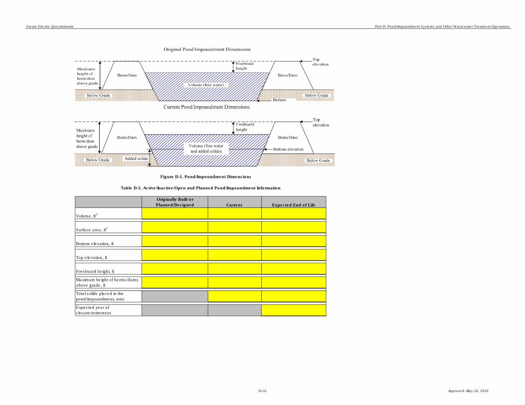
Steam Electric Questionnaire Part D. Pond/Impoundment Systems and Other Wastewater Treatment Operations
Originally Built or
Planned/Designed Current Expected End of Life
Volume, ft3
Surface area, ft2
Bottom elevation, ft
Top elevation, ft
Freeboard height, ft
Maximum height of berms/dams
above grade, ft
Total solids placed in the
pond/impoundment, tons
Expected year of
closure/retirement
Table D-5. Active/Inactive/Open and Planned Pond/Impoundment Information
Figure D-1. Pond/Impoundment Dimensions
D-16 Approved: May 20, 2010

Steam Electric Questionnaire Part D. Pond/Impoundment Systems and Other Wastewater Treatment Operations
CBI? D4-4.
(Complete Table D-6)
Liner Layer Number (number
from inner to outer layer) Type of Liner
Thickness of Liner Layer
(cm)
Permeability of Liner Layer
(cm/sec)
CBI? D4-5.
Year of last dredging
Frequency of dredging that year, dpy
Amount of material removed that year, tons
Number of times dredged in the last five years
Number of days dredged in the last five years
Amount of material removed in the last five years, tons
(Skip to Question D4-7)
(Pond/Impoundment is planned to be constructed. Skip to Question D4-10)
Table D-6. Pond/Impoundment Unit Liner
Does the pond/impoundment unit have a liner ?
(Pond/Impoundment is planned to be constructed. Information is currently unavailable. Skip to Question D4-10).
(Skip to Question D4-5)
Has the pond/impoundment unit ever been dredged?
Yes (Provide following information)
No
NA
Yes
Yes
No
NA
Compacted clay
Geosynthetic clay
High density polyethylene (HDPE)
Other (provide below:)
Yes
Compacted clay
Geosynthetic clay
High density polyethylene (HDPE)
Other (provide below:)
Compacted clay
Geosynthetic clay
High density polyethylene (HDPE)
Other (provide below:)
Compacted clay
Geosynthetic clay
High density polyethylene (HDPE)
Other (provide below:)
D-17 Approved: May 20, 2010

Steam Electric Questionnaire Part D. Pond/Impoundment Systems and Other Wastewater Treatment Operations
CBI? D4-6.
CBI? D4-7.
(Continue)
CBI? D4-8.
CBI? D4-9.
$
CBI? D4-10.
(Skip to Question D4-12)
Provide the total cost associated with the expansion(s). Total costs should include labor, materials, energy, hazardous and nonhazardous waste disposal, purchased equipment, installation, buildings, site preparation, land,
engineering costs, construction expenses, and any other costs available.
Total cost of expansion
Indicate where the dredged solids are transferred or are planned to be transferred.
Has the pond/impoundment unit been expanded since the date it was built?
Describe any expansion(s), since January 1, 2000, to the pond/impoundment unit, including the starting and ending dimensions.
Identify the type of expansion.
Indicate the pollutants targeted for removal by this pond/impoundment unit using techniques other than solely settling (e.g., adding chemicals to remove certain metals). [Check all boxes that apply.]
(Skip to Question D4-10)
(Pond/Impoundment is planned to be constructed. Skip to Question D4-10)
Dredged solids used in embankment construction.
Dredged solids transferred to landfill.
Dredged solids marketed/sold for reuse.
Other (Explain):
Yes
Yes
No
NA
Yes
Yes
Metals (specify):
TSS
Nitrogen compounds (ammonia, nitrate, nitrite)
Organic Acids
Chlorine or other oxidizing agents
Oil and grease
Other:
NA
Yes
Lateral expansion
Vertical expansion
Both lateral and vertical expansion
Yes
D-18 Approved: May 20, 2010

Steam Electric Questionnaire Part D. Pond/Impoundment Systems and Other Wastewater Treatment Operations
CBI? D4-11.
Pollutant:
Limitation:
Pollutant:
Limitation:
Pollutant:
Limitation:
CBI? D4-12.
(Complete Table D-7)
Chemical Type Trade Name Manufacturer Purpose
Location of
Chemical
Addition
Average Dose
Concentration
(g/L)
Frequency of
Addition (dpy)
Average Addition Rate (gpd or
lb/day)
Table D-7. Chemicals Used in Pond/Impoundment Unit Operations
(Pond/impoundment is planned to be constructed. Provide information in Table D-7 to the extent possible based on plans.)
Did the plant add chemicals to this pond/impoundment unit in 2009?
Note that "Chemical Type" refers to the generic name of the chemical added to the pond/impoundment (e.g., lime, sodium hydroxide, alum, polymer ). “Average Dose Concentration” refers to the average
concentration of the chemical within the pond/impoundment unit just after it is added to the unit. In the “Location of Chemical Addition” column, indicate where within or near the pond/impoundment the
chemical is added (e.g., within the pond/impoundment near the process wastewater influent point, within the pond/impoundment near the effluent, in the effluent/discharge canal). If chemical addition is known
only on a yearly basis, divide the yearly value by the approximate number of days the plant added chemicals (which should be the same estimate for the "Frequency of Addition" column).
Of the pollutants listed in D4-10, which effluent limitation(s) drives/will drive the operation of this pond/impoundment unit? Provide the pollutant and the limitation (mg/L or ug/L).
(Skip to Section 4.2)
Yes
Yes
No
NA
gpd
lb/day
Solid
Liquid
lb/day
gpd
gpd
lb/day
gpd
lb/day
gpd
lb/day
Solid
Liquid
Solid
Liquid
Solid
Liquid
Solid
Liquid
Yes
Units
Units
Units
D-19 Approved: May 20, 2010

Steam Electric Questionnaire Part D. Pond/Impoundment Systems and Other Wastewater Treatment Operations
Plant ID: Insert Plant ID
Plant Name: Insert Plant Name
Pond/Impoundment Unit ID: Insert Unit ID
Part: D
Section Title: 4.2. Closed Pond/Impoundment Unit Information
Instructions:
CBI? D4-13.
(Continue)
Are there any ponds/impoundments closed on or after January 1, 2000, including those located on non-adjoining property, that
were used for the storage, treatment, and/or disposal of residues or by-products (or sludges or water streams containing the
residues or by-products) from the combustion of coal, petroleum coke, or oil, including but not limited to fly ash, bottom ash, boiler
slag, or flue gas emission control residues?
Complete Section 4.2 (Questions D4-13 through D4-24) for all pond/impoundment units closed on or after January 1, 2000,
including those located on non-adjoining property, that were used for the storage, treatment, and/or disposal of process
wastewater , residues , or by-products (or sludges or water streams containing the residues or by-products) from the combustion of
coal, petroleum coke, or oil, including but not limited to fly ash, bottom ash, boiler slag, or flue gas emission control residues (use
pond/impoundment unit IDs assigned in Table A-4).
Make a copy of Section 4.2 for each closed pond/impoundment unit, including those located on non-adjoining property, that was
used for the storage, treatment, and/or disposal of process wastewater, residues, or by-products (or sludges or water streams
containing the residues or by-products) from the combustion of coal, petroleum coke, or oil, including but not limited to fly ash ,
bottom ash , boiler slag, or flue gas emission control residues using the "Copy Section 4.2" button below.
NOTE: If a pond/impoundment was part of a broader wastewater treatment system containing non-pond wastewater
treatment units (e.g., a pond/impoundment unit in a biological wastewater treatment system), complete questions in this
section for the pond/impoundment unit.
(Skip to Section 5.1)
Copy Section 4.2
Yes
Yes
No
D-20 Approved: May 20, 2010

Steam Electric Questionnaire Part D. Pond/Impoundment Systems and Other Wastewater Treatment Operations
CBI? D4-14.
Date Closed (month/day/year)
Life of pond/impoundment unit (years, actual)
Number of cells in pond/impoundment unit
CBI? D4-15.
Originally Built End of Life
Volume, ft3
Surface area, ft2
Bottom elevation, ft
Top elevation, ft
Freeboard height, ft
Maximum height of
berms/dams above grade, ft
Total solids placed in the
pond/impoundment, tons
Table D-8. Closed Pond/Impoundment Information
Provide the date the pond/impoundment unit was closed, the actual life of the pond/impoundment unit, and the number of cells in
the pond/impoundment unit.
Complete Table D-8. Provide the pond/impoundment unit's volume, surface area, bottom and top elevation, freeboard height,
maximum height of berms and dams above the surrounding grade, and the total quantity of solids placed in the pond/impoundment
when it was originally built and at its end of life, prior to any solids removal/cleaning. Volume should reflect original and final
(accounting for any expansions) free water volume, including the stored solids. Please refer back to Figure D-1 for an illustration of
pond/impoundment dimensions.
Yes
Yes
D-21 Approved: May 20, 2010

Steam Electric Questionnaire Part D. Pond/Impoundment Systems and Other Wastewater Treatment Operations
CBI? D4-16.
(Complete Table D-9)
Liner Layer Number
(number from inner to
outer layer) Type of Liner
Thickness of Liner
Layer (cm)
Permeability of Liner Layer
(cm/sec)
(Skip to Question D4-17)
Table D-9. Pond/Impoundment Unit Liner
Does the pond/impoundment unit have a liner ?Yes
Compacted clay
Geosynthetic clay
High density polyethylene (HDPE)
Other (provide below:)
Compacted clay
Geosynthetic clay
High density polyethylene (HDPE)
Other (provide below:)
Compacted clay
Geosynthetic clay
High density polyethylene (HDPE)
Other (provide below:)
Compacted clay
Geosynthetic clay
High density polyethylene (HDPE)
Other (provide below:)
Compacted clay
Geosynthetic clay
High density polyethylene (HDPE)
Other (provide below:)
Yes
No
D-22 Approved: May 20, 2010

Steam Electric Questionnaire Part D. Pond/Impoundment Systems and Other Wastewater Treatment Operations
CBI? D4-17.
(Complete Table D-10)
Cap/Cover Layer Number
(number from inner to
outer layer) Type of Cap/Cover Layer
Thickness of
Cap/Cover Layer (cm)
Permeability of Cap/Cover
Layer (cm/sec)
(Skip to Question D4-18)
Table D-10. Pond/Impoundment Unit Cap/Cover
Does the pond/impoundment unit have a cap/cover?
Yes
No
Yes
Compacted clay
Geosynthetic clay
Vegetative cover
High density polyethylene (HDPE)
Other (provide below:)
Compacted clay
Geosynthetic clay
Vegetative cover
High density polyethylene (HDPE)
Other (provide below:)
Compacted clay
Geosynthetic clay
Vegetative cover
High density polyethylene (HDPE)
Other (provide below:)
D-23 Approved: May 20, 2010

Steam Electric Questionnaire Part D. Pond/Impoundment Systems and Other Wastewater Treatment Operations
Compacted clay
Geosynthetic clay
Vegetative cover
High density polyethylene (HDPE)
Other (provide below:)
Compacted clay
Geosynthetic clay
Vegetative cover
High density polyethylene (HDPE)
Other (provide below:)
Compacted clay
Geosynthetic clay
Vegetative cover
High density polyethylene (HDPE)
Other (provide below:)
D-24 Approved: May 20, 2010

Steam Electric Questionnaire Part D. Pond/Impoundment Systems and Other Wastewater Treatment Operations
CBI? D4-18.
(Continue)
CBI? D4-19.
CBI? D4-20.
$
CBI? D4-21.
(Provide a copy of the closure plan)
(Continue)
(Skip to Question 4-21)
Was the pond/impoundment unit expanded during its life?
Identify the type of expansion.
Describe any expansion(s), since January 1, 2000, to the pond/impoundment unit, including the starting and ending dimensions.
Did the plant have a closure plan for this pond/impoundment unit?
Provide the total cost associated with the expansion(s). Total costs should include labor, materials, energy, hazardous and
nonhazardous waste disposal, purchased equipment, installation, buildings, site preparation, land, engineering costs, construction
expenses, and any other costs available.
Total cost of expansion
Yes
No
Lateral expansion
Vertical expansion
Both lateral and vertical expansions
Yes
No
Yes
Yes
Yes
Yes
D-25 Approved: May 20, 2010

Steam Electric Questionnaire Part D. Pond/Impoundment Systems and Other Wastewater Treatment Operations
CBI? D4-22.
CBI? D4-23. Has the plant built any structures on top of the closed pond/impoundment?
(Continue)
CBI? D4-24. Is the plant performing or does it intend to perform long-term groundwater, soil, or overflow monitoring of this closed
pond/impoundment unit?
Provide a description of the structure(s) and any challenges that the plant faced building on top of the pond/impoundment.
(Skip to Question D4-24)
Describe the closure process, the required steps, and the costs associated with the closure.
Note: Total costs should include labor, materials, energy, hazardous and nonhazardous waste disposal, purchased
equipment, installation, buildings, site preparation, land, engineering costs, construction expenses, and any other costs
available.
Note: If you attached a closure plan for the previous question that includes information on the required steps and
associated costs of the closure, do not answer this question and indicate that the information is provided in the attached
closure plan.
Information provided in attached closure plan.
Yes
Yes
Yes
Yes
No
Yes
Yes. Describe the monitoring plan:
No
D-26 Approved: May 20, 2010
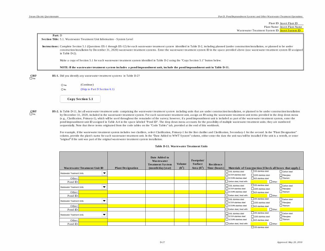
Steam Electric Questionnaire Part D. Pond/Impoundment Systems and Other Wastewater Treatment Operations
Plant ID: Insert Plant ID
Plant Name: Insert Plant Name
Wastewater Treatment System ID: Insert System ID
Part: D
Section Title:
Instructions:
CBI? D5-1.
(Continue)
CBI? D5-2.
Plant Designation
Date Added to
Wastewater
Treatment System
(month/day/year)
Volume
(ft3)
Footprint/
Surface
Area (ft2)
Residence
Time (hours)
Other:
Pond ID:
Other:
Pond ID:
Other:
Pond ID:
Other:
Pond ID:
(Skip to Part D Section 6.1)
5.1. Wastewater Treatment Unit Information - System Level
Did you identify any wastewater treatment systems in Table D-2?
Wastewater Treatment Unit ID
Table D-11. Wastewater Treatment Units
Complete Section 5.1 (Questions D5-1 through D5-12) for each wastewater treatment system identified in Table D-2, including planned (under construction/installation, or planned to be under
construction/installation by December 31, 2020) wastewater treatment systems. Enter the wastewater treatment system ID in the space provided above (use wastewater treatment system ID assigned
in Table D-2).
Make a copy of Section 5.1 for each wastewater treatment system identified in Table D-2 using the "Copy Section 5.1" button below.
NOTE: If the wastewater treatment system includes a pond/impoundment unit, include the pond/impoundment unit in Table D-11.
Materials of Construction [Check all boxes that apply.]
In Table D-11, list all wastewater treatment units comprising the wastewater treatment system including units that are under construction/installation, or planned to be under construction/installation
by December 31, 2020, included in the wastewater treatment system. For each wastewater treatment unit, assign an ID using the wastewater treatment unit terms provided in the drop down menu
(e.g., Clarification, Primary-1), which will be used throughout the remainder of the survey; however, if a pond/impoundment unit is included as part of the wastewater treatment system, enter the
pond/impoundment unit ID assigned in Table A-4 in the space labeled "Pond ID". The drop down menu accounts for the possibility of multiple wastewater treatment units; they are numbered
sequentially. Note that these terms originated from the code tables on the "Code Tables" tab, provided at the end of this workbook.
For example, if the wastewater treatment system includes two clarifiers, select Clarification, Primary-1 for the first clarifier and Clarification, Secondary-1 for the second. In the “Plant Designation”
column, provide the plant’s name for each wastewater treatment unit. In the “Date Added to WWT System” column, either enter the date the unit was/will be installed if the unit is a retrofit, or enter
“original” if the unit was part of the original wastewater treatment system installation.
Yes
Wastewater Treatment Units
Wastewater Treatment Units
Wastewater Treatment Units
Wastewater Treatment Units
Copy Section 5.1
Yes
Yes
No
316L stainless steel
317LM stainless steel
317LMN stainless steel
2205 stainless steel
255 stainless steel
625 stainless steel
Carbon steel
Carbon steel, lined with: Other:
Titanium
Fiberglass
316L stainless steel
317LM stainless steel
317LMN stainless steel
2205 stainless steel
255 stainless steel
625 stainless steel
Carbon steel
Carbon steel, lined with: Other:
Titanium
Fiberglass
316L stainless steel
317LM stainless steel
317LMN stainless steel
2205 stainless steel
255 stainless steel
625 stainless steel
Carbon steel
Carbon steel, lined with: Other:
Titanium
Fiberglass
316L stainless steel
317LM stainless steel
317LMN stainless steel
2205 stainless steel
255 stainless steel
625 stainless steel
Carbon steel
Carbon steel, lined with: Other:
Titanium
Fiberglass
255 stainless steel
D-27 Approved: May 20, 2010

Steam Electric Questionnaire Part D. Pond/Impoundment Systems and Other Wastewater Treatment Operations
Other:
Pond ID:
Other:
Pond ID:
Other:
Pond ID:
Other:
Pond ID:
Other:
Pond ID:
Other:
Pond ID:
Other:
Pond ID:
Other:
Pond ID:
Other:
Pond ID:
Other:
Pond ID:
Other:
Pond ID:
Other:
Pond ID:
Other:
Pond ID:
Other:
Pond ID:
Other:
Pond ID:
Wastewater Treatment Units
Wastewater Treatment Units
Wastewater Treatment Units
Wastewater Treatment Units
Wastewater Treatment Units
Wastewater Treatment Units
Wastewater Treatment Units
Wastewater Treatment Units
Wastewater Treatment Units
Wastewater Treatment Units
Wastewater Treatment Units
Wastewater Treatment Units
Wastewater Treatment Units
Wastewater Treatment Units
Wastewater Treatment Units
316L stainless steel
317LM stainless steel
317LMN stainless steel
2205 stainless steel
255 stainless steel
625 stainless steel
Carbon steel
Carbon steel, lined with: Other:
Titanium
Fiberglass
316L stainless steel
317LM stainless steel
317LMN stainless steel
2205 stainless steel
255 stainless steel
625 stainless steel
Carbon steel
Carbon steel, lined with: Other:
Titanium
Fiberglass
316L stainless steel
317LM stainless steel
317LMN stainless steel
2205 stainless steel
255 stainless steel
625 stainless steel
Carbon steel
Carbon steel, lined with: Other:
Titanium
Fiberglass
316L stainless steel
317LM stainless steel
317LMN stainless steel
2205 stainless steel
255 stainless steel
625 stainless steel
Carbon steel
Carbon steel, lined with: Other:
Titanium
Fiberglass
316L stainless steel
317LM stainless steel
317LMN stainless steel
2205 stainless steel
255 stainless steel
625 stainless steel
Carbon steel
Carbon steel, lined with: Other:
Titanium
Fiberglass
316L stainless steel
317LM stainless steel
317LMN stainless steel
2205 stainless steel
255 stainless steel
625 stainless steel
Carbon steel
Carbon steel, lined with: Other:
Titanium
Fiberglass
316L stainless steel
317LM stainless steel
317LMN stainless steel
2205 stainless steel
255 stainless steel
625 stainless steel
Carbon steel
Carbon steel, lined with: Other:
Titanium
Fiberglass
316L stainless steel
317LM stainless steel
317LMN stainless steel
2205 stainless steel
255 stainless steel
625 stainless steel
Carbon steel
Carbon steel, lined with: Other:
Titanium
Fiberglass
316L stainless steel
317LM stainless steel
317LMN stainless steel
2205 stainless steel
255 stainless steel
625 stainless steel
Carbon steel
Carbon steel, lined with: Other:
Titanium
Fiberglass
316L stainless steel
317LM stainless steel
317LMN stainless steel
2205 stainless steel
255 stainless steel
625 stainless steel
Carbon steel
Carbon steel, lined with: Other:
Titanium
Fiberglass
316L stainless steel
317LM stainless steel
317LMN stainless steel
2205 stainless steel
255 stainless steel
625 stainless steel
Carbon steel
Carbon steel, lined with: Other:
Titanium
Fiberglass
316L stainless steel
317LM stainless steel
317LMN stainless steel
2205 stainless steel
255 stainless steel
625 stainless steel
Carbon steel
Carbon steel, lined with: Other:
Titanium
Fiberglass
316L stainless steel
317LM stainless steel
317LMN stainless steel
2205 stainless steel
255 stainless steel
625 stainless steel
Carbon steel
Carbon steel, lined with: Other:
Titanium
Fiberglass
316L stainless steel
317LM stainless steel
317LMN stainless steel
2205 stainless steel
255 stainless steel
625 stainless steel
Carbon steel
Carbon steel, lined with: Other:
Titanium
Fiberglass
316L stainless steel
317LM stainless steel
317LMN stainless steel
2205 stainless steel
255 stainless steel
625 stainless steel
Carbon steel
Carbon steel, lined with: Other:
Titanium
Fiberglass
255 stainless steel
D-28 Approved: May 20, 2010

Steam Electric Questionnaire Part D. Pond/Impoundment Systems and Other Wastewater Treatment Operations
Other:
Pond ID:
Other:
Pond ID:
Other:
Pond ID:
Other:
Pond ID:
CBI? D5-3.
Average design flow rate, gpm
Maximum design flow rate, gpm
Typical flow rate in 2009, gpm
Maximum daily flow rate in 2009, gpm
Maximum daily flow rate in 2009, gpd
Duration of effluent transfers from treatment system in 2009, hpd
Frequency of effluent transfers from treatment system in 2009, dpy
CBI? D5-4.
(Skip to Question D5-6)
Provide the design flow rate for the wastewater treatment system, as well as both the average and maximum flow rates for 2009. In addition, provide the duration and frequency of the effluent
transfers from the wastewater treatment system in 2009. If the wastewater treatment system is planned, only provide the design flow rate and enter "NA" in all other fields.
Indicate the pollutants targeted for removal by this wastewater treatment system using techniques other than solely settling (e.g., adding chemicals to remove certain metals).
[Check all boxes that apply.]
Yes
Wastewater Treatment Units
Wastewater Treatment Units
Wastewater Treatment Units
Wastewater Treatment Units
316L stainless steel
317LM stainless steel
317LMN stainless steel
2205 stainless steel
255 stainless steel
625 stainless steel
Carbon steel
Carbon steel, lined with: Other:
Titanium
Fiberglass
316L stainless steel
317LM stainless steel
317LMN stainless steel
2205 stainless steel
255 stainless steel
625 stainless steel
Carbon steel
Carbon steel, lined with: Other:
Titanium
Fiberglass
316L stainless steel
317LM stainless steel
317LMN stainless steel
2205 stainless steel
255 stainless steel
625 stainless steel
Carbon steel
Carbon steel, lined with: Other:
Titanium
Fiberglass
316L stainless steel
317LM stainless steel
317LMN stainless steel
2205 stainless steel
255 stainless steel
625 stainless steel
Carbon steel
Carbon steel, lined with: Other:
Titanium
Fiberglass
Metals (specify):
TSS
Nitrogen compounds (ammonia, nitrate, nitrite)
Organic Acids
Chlorine or other oxidizing agents
Oil and grease
Other:
NA
Yes
D-29 Approved: May 20, 2010

Steam Electric Questionnaire Part D. Pond/Impoundment Systems and Other Wastewater Treatment Operations
CBI? D5-5.
Pollutant:
Limitation:
Pollutant:
Limitation:
Pollutant:
Limitation:
CBI? D5-6.
(Continue)
(Skip to Question D5-8)
CBI? D5-7. Is the plant currently performing sulfide addition?
CBI? D5-8.
CBI? D5-9.
CBI? D5-10.
Provide information on any impacts that climate had, or will have, on the installation of the wastewater treatment system (e.g., equipment had to be housed inside due to cold winters, extra insulation
was necessary to protect equipment in winter, warm climate allowed all wastewater treatment to be located outdoors).
Provide any bid proposals and/or engineering reports that were prepared since January 1, 1995 for the wastewater treatment system.
Note: All bid proposals and/or engineering reports originally submitted to the plant as CBI, should be marked CBI for the purpose of this collection request.
Of the pollutants listed in D5-4, which effluent limitation(s) drives/will drive the operation of this wastewater treatment system? Provide the pollutant and the limitation (mg/L or
ug/L).
Is this wastewater treatment system capable of performing sulfide addition?
Provide information on any impacts that space availability had, or will have, on the design and/or cost of the wastewater treatment system (e.g., cost increases due to fitting the wastewater treatment
system units into tight spaces and/or moving other equipment to accommodate the treatment system units).
I have attached the bid proposals/engineering reports.
I did not attach the bid proposals/engineering reports. Below, explain why:
Yes
Yes
Yes
Yes
Units
Units
Units
Yes
Yes
No
Yes
Yes
No
D-30 Approved: May 20, 2010

Steam Electric Questionnaire Part D. Pond/Impoundment Systems and Other Wastewater Treatment Operations
CBI? D5-11.
Description of Improvement
Expected Date of
Improvement
(month/day/year)
Total
Capital
Cost ($)
Other:
Pond ID:
Other:
Pond ID:
Other:
Pond ID:
Other:
Pond ID:
Other:
Pond ID:
CBI? D5-12.
(Continue)
(Skip to Section 5.2)
Table D-12. Planned Improvements to the Wastewater Treatment System
In Table D-12, list all planned improvements (including those currently under construction/installation or those planned to be under construction/installation by December 31, 2020) to the wastewater
treatment system. For each planned improvement to the wastewater treatment system, provide the WWT Unit ID the improvement pertains to (if applicable), using the terms in the drop down menu;
however, if the improvement relates directly to a pond/impoundment, use the pond/impoundment ID assigned in Table A-4. Provide a description of the improvement, the expected date of the
improvement, and the total capital cost related to the improvement.
Note: Total capital costs should include purchased equipment, installation, buildings, site preparation, land, engineering costs, construction expenses, and any other costs available.
Please identify which pollutants and/or limits, in particular, the improvements or system will target.
Wastewater Treatment Unit ID
Were any of the above planned improvements to the wastewater treatment system, or the planned wastewater treatment system, planned in preparation for potential limit changes in the future?
Yes
Wastewater Treatment Units
Wastewater Treatment Units
Wastewater Treatment Units
Wastewater Treatment Units
Wastewater Treatment Units
Yes
Yes
No
D-31 Approved: May 20, 2010
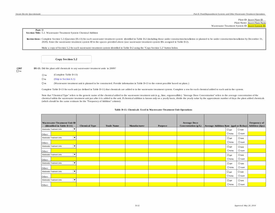
Steam Electric Questionnaire Part D. Pond/Impoundment Systems and Other Wastewater Treatment Operations
Plant ID: Insert Plant ID
Plant Name: Insert Plant Name
Wastewater Treatment System ID: Insert System ID
Part: DSection Title:
Instructions:
CBI? D5-13.
(Complete Table D-13)
(Skip to Section 6.1)
Chemical Type Trade Name Manufacturer Purpose
Average Dose
Concentration (g/L)
Frequency of
Addition (dpy)
Other:
Other:
Other:
Other:
Other:
Other:
Other:
Wastewater Treatment Unit ID
(Identified in Table D-11)
5.2. Wastewater Treatment System Chemical Addition
Average Addition Rate (gpd or lb/day)
Complete Section 5.2 (Question D5-13) for each wastewater treatment system identified in Table D-2 (including those under construction/installation or planned to be under construction/installation by December 31,
2020). Enter the wastewater treatment system ID in the spaces provided above (use wastewater treatment system IDs assigned in Table D-2).
Make a copy of Section 5.2 for each wastewater treatment system identified in Table D-2 using the "Copy Section 5.2" button below.
Table D-13. Chemicals Used in Wastewater Treatment Unit Operations
Complete Table D-13 for each unit (as defined in Table D-11) that chemicals are added to in the wastewater treatment system. Complete a row for each chemical added to each unit in the system.
Note that "Chemical Type" refers to the generic name of the chemical added to the wastewater treatment unit (e.g., lime, organosulfide). "Average Dose Concentration" refers to the average concentration of the
chemical within the wastewater treatment unit just after it is added to the unit. If chemical addition is known only on a yearly basis, divide the yearly value by the approximate number of days the plant added chemicals
(which should be the same estimate for the "Frequency of Addition" column).
Did the plant add chemicals to any wastewater treatment units in 2009?
(Wastewater treatment unit is planned to be constructed. Provide information in Table D-13 to the extent possible based on plans.)
Yes
No
NA
gpd
lb/day
gpd
lb/day
gpd
lb/day
gpd
lb/day
gpd
lb/day
Solid
Liquid
Solid
Liquid
Solid
Liquid
Solid
Liquid
Solid
Liquid
Copy Section 5.2
gpd
lb/day
gpd
lb/day
Solid
Liquid
Solid
Liquid
Wastewater Treatment Units
Wastewater Treatment Units
Wastewater Treatment Units
Wastewater Treatment Units
Wastewater Treatment Units
Wastewater Treatment Units
Wastewater Treatment Units
Yes
D-32 Approved: May 20, 2010

Steam Electric Questionnaire Part D. Pond/Impoundment Systems and Other Wastewater Treatment Operations
Other:
Other:
Other:
Other:
Other:
Other:
Other:
Other:
Other:
Other:
Other:
Other:
Other:
Other:
Other:
Other:
Other:
Other:
Other:
Other:
gpd
lb/day
gpd
lb/day
gpd
lb/day
Solid
Liquid
Solid
Liquid
Solid
Liquid
gpd
lb/day
gpd
lb/day
gpd
lb/day
gpd
lb/day
gpd
lb/day
Solid
Liquid
Solid
Liquid
Solid
Liquid
Solid
Liquid
Solid
Liquid
gpd
lb/day
gpd
lb/day
gpd
lb/day
gpd
lb/day
gpd
lb/day
Solid
Liquid
Solid
Liquid
Solid
Liquid
Solid
Liquid
Solid
Liquid
gpd
lb/day
gpd
lb/day
gpd
lb/day
gpd
lb/day
gpd
lb/day
Solid
Liquid
Solid
Liquid
Solid
Liquid
Solid
Liquid
Solid
Liquid
gpd
lb/day
gpd
lb/day
Solid
Liquid
Solid
Liquid
gpd
lb/day
gpd
lb/day
Solid
Liquid
Solid
Liquid
Wastewater Treatment Units
Wastewater Treatment Units
Wastewater Treatment Units
Wastewater Treatment Units
Wastewater Treatment Units
Wastewater Treatment Units
Wastewater Treatment Units
Wastewater Treatment Units
Wastewater Treatment Units
Wastewater Treatment Units
Wastewater Treatment Units
Wastewater Treatment Units
Wastewater Treatment Units
Wastewater Treatment Units
Wastewater Treatment Units
Wastewater Treatment Units
Wastewater Treatment Units
Wastewater Treatment Units
Wastewater Treatment Units
Wastewater Treatment Units
D-33 Approved: May 20, 2010

Steam Electric Questionnaire Part D. Pond/Impoundment Systems and Other Wastewater Treatment Operations
Other:
Other:
gpd
lb/day
gpd
lb/day
gpd
lb/day
Solid
Liquid
Solid
Liquid
Solid
Liquid
gpd
lb/day
gpd
lb/day
gpd
lb/day
Solid
Liquid
Solid
Liquid
Solid
Liquid
Wastewater Treatment Units
Wastewater Treatment Units
Wastewater Treatment Units
D-34 Approved: May 20, 2010

Steam Electric Questionnaire Part D. Pond/Impoundment Systems and Other Wastewater Treatment Operations
Plant ID: Insert Plant ID
Plant Name: Insert Plant Name
Pond/Impoundment System ID or Wastewater Treatment System ID: Insert System ID
Part: D
Section Title:
Instructions:
CBI? D6-1.
(Continue)
(Skip to next Questionnaire Part)
CBI? D6-2.
O&M Cost Category
No. of workers
Operating labor $ $ hpd
dpy
No. of workers
Maintenance labor $ $ hpd
dpy
Maintenance materials $
Chemicals $
6.1. Pond/Impoundment System and Wastewater Treatment System Costs
Provide annual O&M cost data in Table D-14 for each pond/impoundment system identified in Table D-1, that includes at least one pond/impoundment that began operating at the plant on or
after January 1, 2000, and/or wastewater treatment system, identified in Table D-2, that began operating at the plant on or after January 1, 2000, that was operated in 2009. Provide best
engineering estimates when actual data are not readily available. If you provide an estimate, note the methods that were used to make the estimates in the Comments page.
2009 Annual Cost 2009 Rate 2009 Staffing/ Consumption
Complete Sections 6.1 and 6.2 (Questions D6-1 through D6-6) for each pond/impoundment system identified in Table D-1, that includes at least one pond/impoundment that began operating
at the plant on or after January 1, 2000. For example if a pond/impoundment system began operating in 1996, but a new pond/impoundment was added in 2002, information regarding the
pond/impoundment system must be provided for this section. Also complete Sections 6.1 and 6.2 (Questions D6-1 through D6-6) for each wastewater treatment system identified in Table D-2
that began operating at the plant on or after January 1, 2000. These pond/impoundment systems and wastewater treatment systems also include those under construction/installation or
planned to be under construction/installation by December 31, 2020. Enter the pond/impoundment system ID or wastewater treatment system ID in the space provided above (use
pond/impoundment system IDs and wastewater treatment system IDs assigned in Table D-1 and Table D-2).
Make a copy of Sections 6.1 and 6.2 for each pond/impoundment system and/or wastewater treatment system identified in Table D-1 and Table D-2 using the "Copy Section 6.1 and 6.2"
button below. Just pressing this button once will generate copies of both tabs.
Table D-14. O&M Cost for the Pond/Impoundment System or Wastewater Treatment System for 2009
Note: Do NOT include corrective actions in the O&M costs for the ponds/impoundments in the system.
Did any ponds/impoundments , including those that are part of a pond/impoundment system identified in Table D-1, and/or wastewater treatment systems, identified in Table D-2, begin
operating (or plan to begin operating) after January 1, 2000?
per hour (average
rate of labor)
per hour (average
rate of labor)
Yes
Copy Section 6.1 and 6.2
Yes
Yes
No
D-35 Approved: May 20, 2010

Steam Electric Questionnaire Part D. Pond/Impoundment Systems and Other Wastewater Treatment Operations
Energy - Power for pumping $ $ per kWh kWh/hr
Energy - Power for operations other than pumping $ $ per kWh kWh/hr
Steam $ $ per pound pounds/hr
Hazardous Sludge Disposal - Dredging $ $ per
Hazardous Sludge Disposal - Landfilling $ $ per
Nonhazardous Sludge Disposal - Dredging $ $ per
Nonhazardous Sludge Disposal - Landfilling $ $ per
Other:
$
Other:
$
Total O&M Cost (2009) $
CBI? D6-3. Provide cost data in Table D-15 only for those ponds/impoundments, within the pond/impoundment system identified in Table D-1, that began operating on or after January 1, 2000, and/or
wastewater treatment systems, identified in Table D-2, that began operating at the plant on or after January 1, 2000. These ponds/impoundments and wastewater treatment systems include
retired/closed ponds/impoundments, planned ponds/impoundments, and planned wastewater treatment systems (including those under construction/installation or planned to be under
construction/installation by December 31, 2020). Additionally, include any costs incurred by the pond/impoundment system since January 1, 2000. For example, if a pond/impoundment system
was installed in 1996, and one new pond was added in 2002, report the capital costs for the new pond only, and any capital costs (i.e., piping, pumps) incurred for the entire pond/impoundment
system since 2000.
Provide best engineering estimates when actual data are not readily available. For all costs, do not adjust for inflation. For example, if the plant incurred a land cost in 2002, enter the cost in the
“Cost” column and enter “2002” in the “Year on which Cost is Based” column.
NOTE: If no records are available on this wastewater treatment system, provide an explanation in the Comments page.
Gallon
Ton
Gallon
Ton
Gallon
Ton
Gallon
Ton
Yes
D-36 Approved: May 20, 2010

Steam Electric Questionnaire Part D. Pond/Impoundment Systems and Other Wastewater Treatment Operations
Project
$
$
$
$
$
Total Direct Costs $
Engineering Costs (includes process design and general engineering,
cost engineering, consulting fees, supervision, inspection for each
category below:
a. Engineering Contract Firm Costs $
b. Owner's Overhead Engineering Costs $
$
$
$
Total Indirect Costs $
Total Capital Cost $
Site preparation (includes site clearing, all demolition, grading, roads,
walking areas, fences)
Cost
Table D-15. Capital Cost for the Pond/Impoundment System or Wastewater Treatment System
Year on which Cost is
Based
Purchased equipment installation (includes installation of all
equipment; piping; instrumentation/calibration; electrical equipment;
mechanical equipment; structural supports, insulation, and paint)
Construction expenses (includes temporary construction offices,
roads, communications, fencing; construction tools and equipment;
permits, taxes, insurance)
Other Contractor's Fees
Contingency actually expended (to compensate for unpredictable
events such as storms, floods, strikes, price changes, errors in
estimates, design changes, etc.)
Indirect Costs
Direct Costs
Purchased equipment (includes all equipment for the installation or
the upgrade: mechanical equipment; piping; instrumentation;
electrical equipment; spare parts; freight charges; taxes; insurance;
and duties)
Land (includes property costs and survey fees)
Buildings (buildings constructed to house pond/impoundment system
and/or wastewater treatment system components, operator rooms, or
other operations associated with the system; also includes plumbing,
heating, ventilation, dust collection, air conditioning, lighting,
telephones, intercoms, painting, sprinklers, fire alarms)
Hired outside engineering firm to oversee design and/or installation of the treatment system.
D-37 Approved: May 20, 2010

Steam Electric Questionnaire Part D. Pond/Impoundment Systems and Other Wastewater Treatment Operations
CBI? D6-4.
(Skip to Question D6-5)
(Continue)
CBI? D6-5.
CBI? D6-6. If applicable, indicate whether the FGD wastewater treatment system, for which the plant provide capital cost data in Table D-15, was purchased as part of the FGD scrubber package.
Are all components of the pond/impoundment system and/or wastewater treatment system included in the capital costs reported in Table D-15?
Please explain what system components are included in the capital costs listed in Table D-15. Additionally, identify the key components of the pond/impoundment system and/or wastewater
treatment system that are not included in the capital costs reported in Table D-15.
If applicable, indicate whether the FGD wastewater treatment system, for which the plant provided capital cost data in Table D-15, was a retrofit or was installed when the FGD scrubber
system was installed.
FGD wastewater treatment system was a retrofit
FGD wastewater treatment system was installed when the FGD scrubber system was installed
NA
Yes
Yes
FGD wastewater treatment system was purchased as part of the FGD scrubber package
FGD wastewater treatment system was not purchased as part of the FGD scrubber package
NA
Yes Yes
No
D-38 Approved: May 20, 2010

Steam Electric Questionnaire Part D. Pond/Impoundment Systems and Other Wastewater Treatment Operations
Plant ID: Insert Plant ID
Plant Name: Insert Plant Name
Pond/Impoundment System ID or Wastewater Treatment System ID: Insert System ID
Part: D
Section Title:
Instructions:
CBI? D6-7.
Examples of ancillary equipment:
Aerator
Agitator
Chemical feed system (specify chemicals)
Pump, sludge (specify purpose/location)
Pump, wastewater (specify purpose/location)
6.2. Pond/Impoundment System and Wastewater Treatment System Equipment
Complete Section 6.2 (Question D6-7) for all ancillary pieces of equipment included in the
pond/impoundment or wastewater treatment system that contribute to the capital costs provided in Table
D-15.
Note: This tab will copy with every copy made for the previous tab (Part D Section 6.1) as the
information is directly related.
In Table D-16, list any ancillary pieces of equipment (i.e., equipment such as pumps and agitators)
included in the pond/impoundment system or wastewater treatment system that contribute significantly to
the capital costs provided in Table D-16 and provide the total number of pieces of that equipment included
in the system. Refer to the examples of ancillary equipment shown below.
Yes
D-39 Approved: May 20, 2010

Steam Electric Questionnaire Part D. Pond/Impoundment Systems and Other Wastewater Treatment Operations
Ancillary Equipment (if applicable)
Number of Ancillary
Equipment Pieces in the
System
Pump, sludge (serving underflow
from clarifiers)2
Table D-16. Ancillary Equipment of the Pond/Impoundment
System or Wastewater Treatment System
D-40 Approved: May 20, 2010

Steam Electric Questionnaire Part D. Pond/Impoundment Systems and Other Wastewater Treatment Operations
D-41 Approved: May 20, 2010

Steam Electric Questionnaire Part D. Pond/Impoundment Systems and Other Wastewater Treatment Operations
Plant ID: Insert Plant ID
Plant Name: Insert Plant Name
Part: D
Section Title:
Instructions:
Question
Number
CBI?
CBI?
CBI?
CBI?
CBI?
CBI?
CBI?
CBI?
CBI?
CBI?
CBI?
CBI?
Comments
Cross reference your comments by question number and indicate the confidential status of your comment by checking the box next to “Yes” under "CBI?"
(Confidential Business Information).
Part D Comments
Yes
Yes
Yes
Yes
Yes
Yes
Yes
Yes
Yes
Yes
Yes
Yes
D-42 Approved: May 20, 2010

Steam Electric Questionnaire Part D. Pond/Impoundment Systems and Other Wastewater Treatment Operations
CBI?
CBI?
CBI?
CBI?
CBI?
CBI?
CBI?
CBI?
CBI?
CBI?
CBI?
CBI?Yes
Yes
Yes
Yes
Yes
Yes
Yes
Yes
Yes
Yes
Yes
Yes
D-43 Approved: May 20, 2010

Steam Electric Questionnaire Part D. Pond/Impoundment Systems and Other Wastewater Treatment Operations
Air heater cleaning water AHCW
Ash pile runoff APR Effluent - 1 EFF-1
Boiler blowdown BB Effluent - 2 EFF-2
Boiler fireside cleaning water BFCW Effluent - 3 EFF-3
Boiler tube cleaning water BTCW Effluent - 4 EFF-4
Bottom ash sluice BAS Effluent - 5 EFF-5
Carbon capture wastewater CCAPW Effluent - 6 EFF-6
Coal pile runoff CPR Filter backwash FltBW
Combined ash sluice CAS Sludge SLDG
Combustion turbine cleaning (combustion gas portion of
turbine) water
COMBCW
Combustion turbine cleaning (compressor portion of the
turbine) water
COMPRCW POND-1 Effluent POND-1-EFF
Combustion turbine evaporative coolers blowdown TECB POND-2 Effluent POND-2-EFF
Cooling tower blowdown CTB POND-3 Effluent POND-3-EFF
FGD scrubber purge SCRBP POND-4 Effluent POND-4-EFF
FGD slurry blowdown FGDB POND-5 Effluent POND-5-EFF
Filter Backwash FLTBW POND-6 Effluent POND-6-EFF
Floor drain wastewater FDW POND-7 Effluent POND-7-EFF
Flue gas mercury control system wastewater FGMCW POND-8 Effluent POND-8-EFF
Fly ash sluice FAS POND-9 Effluent POND-9-EFF
General runoff GR POND-10 Effluent POND-10-EFF
Gypsum pile runoff GPR POND-A Effluent POND-A-EFF
Gypsum wash water GYPWW POND-B Effluent POND-B-EFF
Ion exchange wastewater IXW POND-C Effluent POND-C-EFF
Landfill runoff - capped landfill LRC WWT-1 Effluent WWT-1-EFF
Landfill runoff - uncapped landfill LRUC WWT-2 Effluent WWT-2-EFF
Leachate LEACH WWT-3 Effluent WWT-3-EFF
Limestone pile runoff LPR WWT-4 Effluent WWT-4-EFF
Mill reject sluice MRS WWT-5 Effluent WWT-5-EFF
Steam Electric Questionnaire Code Tables
For Use as Effluents from Pond/Impoundment Systems
and/or Wastewater Treatment Systems in Part D, Table D-4.
Process Wastewaters
For Use in Tables and Questions throughout Parts A, B, C, D, and F.
For Use as Influents to Pond/Impoundment Systems and/or
Wastewater Treatment Systems in Part D, Table D-3, AND
Recycled Waters Throughout Questionnaire.
Treated Wastewaters
Approved: May 20, 2010
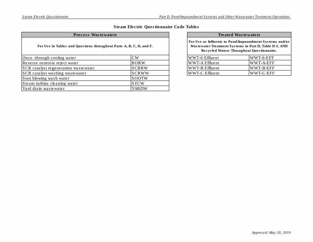
Steam Electric Questionnaire Part D. Pond/Impoundment Systems and Other Wastewater Treatment Operations
Steam Electric Questionnaire Code Tables
Once -through cooling water CW WWT-6 Effluent WWT-6-EFF
Reverse osmosis reject water RORW WWT-A Effluent WWT-A-EFF
SCR catalyst regeneration wastewater SCRRW WWT-B Effluent WWT-B-EFF
SCR catalyst washing wastewater SCRWW WWT-C Effluent WWT-C-EFF
Soot blowing wash water SOOTW
Steam turbine cleaning water STCW
Yard drain wastewater YARDW
For Use in Tables and Questions throughout Parts A, B, C, D, and F.
For Use as Influents to Pond/Impoundment Systems and/or
Wastewater Treatment Systems in Part D, Table D-3, AND
Recycled Waters Throughout Questionnaire.
Process Wastewaters Treated Wastewaters
Approved: May 20, 2010

Steam Electric Questionnaire Part D. Pond/Impoundment Systems and Other Wastewater Treatment Operations
Steam Electric Questionnaire Code Tables
Adsorptive media ADSORB Burned on site BURNAerobic Biological Reactor AERBIO Deep-well injection DWELL
Anaerobic Biological Reactor ANBIO Discharge to POTW POTW
Aerobic/Anaerobic Biological Reactor AER/ANBIO Discharge to PrOTW PrOTW
Chemical Precipitation Reaction Tank 1 - 1 CP-1-1 Discharge to surface water SW
Chemical Precipitation Reaction Tank 1 - 2 CP-1-2 Evaporation EVAP
Chemical Precipitation Reaction Tank 2 - 1 CP-2-1 Hauled off site for reuse
(removal fee)
HAULR - RF
Chemical Precipitation Reaction Tank 2 - 2 CP-2-2 Hauled off site for reuse (given
away)
HAULR - GA
Chemical Precipitation Reaction Tank 3 - 1 CP-3-1 Hauled off site for reuse
(marketed and sold)
SOLD
Chemical Precipitation Reaction Tank 3 - 2 CP-3-2 Hauled off site for disposal HAUL
Clarification, Primary - 1 CL-P-1 Mixed with fly ash for disposal MFA
Clarification, Primary - 2 CL-P-2 On-site landfill (as reported in
Table A-6)
LANDF
Clarification, Secondary - 1 CL-S-1 POND-1 POND-1
Clarification, Secondary - 2 CL-S-2 POND-2 POND-2
Clarification, Tertiary - 1 CL-T-1 POND-3 POND-3
Clarification, Tertiary - 2 CL-T-2 POND-4 POND-4
Constructed wetland - Cell 1 CWL -1 POND-5 POND-5
Constructed wetland - Cell 2 CWL -2 POND-6 POND-6
Constructed wetland - Cell 3 CWL -3 POND-7 POND-7
Constructed wetland - Cell 4 CWL -4 POND-8 POND-8
Constructed wetland - Cell 5 CWL -5 POND-9 POND-9
Constructed wetland - Cell 6 CWL -6 POND-10 POND-10
Constructed wetland system CWTS POND-A POND-A
Equalization, Primary EQ-P POND-B POND-B
Equalization, Secondary EQ-S POND-C POND-C
Filter, Microfiltration - 1 FLT-M-1 WWT-1 WWT-1
Filter, Microfiltration - 2 FLT-M-2 WWT-2 WWT-2
For Use in Tables and Questions Throughout Parts A, C, D,
and F.
Wastewater Treatment Units Destinations
For Use in Tables and Questions Throughout Parts D and F.
Approved: May 20, 2010

Steam Electric Questionnaire Part D. Pond/Impoundment Systems and Other Wastewater Treatment Operations
Steam Electric Questionnaire Code Tables
Filter, Microfiltration - 3 FLT-M-3 WWT-3 WWT-3
Filter, Microfiltration - 4 FLT-M-4 WWT-4 WWT-4
Filter, Sand/Gravity - 1 FLT-S-1 WWT-5 WWT-5
Filter, Sand/Gravity - 2 FLT-S-2 WWT-6 WWT-6
Filter, Sand/Gravity - 3 FLT-S-3 WWT-A WWT-AFilter, Sand/Gravity - 4 FLT-S-4 WWT-B WWT-B
Filter, Ultrafiltration - 1 FLT-U-1 WWT-C WWT-C
Filter, Ultrafiltration - 2 FLT-U-2 Reuse as boiler water RECYC - BW
Filter, Ultrafiltration - 3 FLT-U-3 Reuse as bottom ash sluice RECYC - BAS
Filter, Ultrafiltration - 4 FLT-U-4 Reuse as combined ash sluice RECYC - CAS
Filter press - 1 FP-1 Reuse as FGD slurry
preparation water
RECYC - FGDP
Filter press - 2 FP-2 Reuse as FGD absorber
makeup
RECYC - FGDAB
Holding tank HT Reuse as fly ash sluice RECYC - FAS
Ion exchange IX Reuse as mill reject sluice RECYC - MRS
Natural wetlands NW Reuse in cooling towers RECYC - CW
pH adjustment - 1 PH-1
pH adjustment - 2 PH-2
pH adjustment - 3 PH-3
Reverse osmosis ROS
Pond Unit - 1 SPD-1
Pond Unit - 2 SPD-2
Pond Unit - 3 SPD-3
Pond Unit - 4 SPD-4
Pond Unit - 5 SPD-5
Pond Unit - 6 SPD-6
Pond Unit - 7 SPD-7
Pond Unit - 8 SPD-8
Pond Unit - 9 SPD-9
For Use in Tables and Questions Throughout Parts D and F.For Use in Tables and Questions Throughout Parts A, C, D,
and F.
Wastewater Treatment Units Destinations
Approved: May 20, 2010

Steam Electric Questionnaire Part D. Pond/Impoundment Systems and Other Wastewater Treatment Operations
Steam Electric Questionnaire Code Tables
Pond Unit - 10 SPD-10 Centrifuge - 1 CENT-1Pond Unit - 11 SPD-11 Centrifuge - 2 CENT-2Pond Unit - 12 SPD-12 Centrifuge - 3 CENT-3Pond Unit - 13 SPD-13 Centrifuge - 4 CENT-4Pond Unit - 14 SPD-14 Hydrocyclones - 1 HYC-1
Settling tank - 1 ST-1 Hydrocyclones - 2 HYC-2
Settling tank - 2 ST-2 Hydrocyclones - 3 HYC-3
Settling tank - 3 ST-3 Hydrocyclones - 4 HYC-4
Settling tank - 4 ST-4 Filter press - 1 FP-1
Settling tank - 5 ST-5 Filter press - 2 FP-2
Thickener - 1 TH-1 Thickener - 1 TH-1
Thickener - 2 TH-2 Thickener - 2 TH-2
Vacuum drum filter - 1 VF-1 Vacuum drum filter - 1 VF-1
Vacuum drum filter - 2 VF-2 Vacuum drum filter - 2 VF-2
Vacuum filter belt - 1 VFB-1 Vacuum filter belt - 1 VFB-1
Vacuum filter belt - 2 VFB-2 Vacuum filter belt - 2 VFB-2
For Use in Tables and Questions Throughout Parts D and F. For Use as Planned Solids Handling for the FGD Slurry
Blowdown in Part B Table B-2.
Wastewater Treatment Units Solids Handling
Approved: May 20, 2010

Steam Electric Questionnaire Part D. Pond/Impoundment Systems and Other Wastewater Treatment Operations
Part D Drop DownsProcess Wastewaters
Process Wastewaters
Select
Air heater cleaning water
Ash pile runoff
Boiler blowdown
Boiler fireside cleaning water
Boiler tube cleaning water
Bottom ash sluice
Carbon capture wastewater
Coal pile runoff
Combined ash sluice
Combustion turbine cleaning (combustion gas portion of turbine) water
Combustion turbine cleaning (compressor portion of the turbine) water
Combustion turbine evaporative coolers blowdown
Cooling tower blowdown
FGD scrubber purge
FGD slurry blowdown
Filter Backwash
Floor drain wastewater
Flue gas mercury control system wastewater
Fly ash sluice
General runoff
Gypsum pile runoff
Gypsum wash water
Ion exchange wastewater
Landfill runoff - capped landfill
Landfill runoff - uncapped landfill
Leachate
Limestone pile runoff
Mill reject sluice
Once -through cooling water
Reverse osmosis reject water
SCR catalyst regeneration wastewater
SCR catalyst washing wastewater
Soot blowing wash water
Steam turbine cleaning water
Yard drain wastewater
Other
Treated Wastewaters
Treated Wastewaters
Select
Effluent - 1
Effluent - 2
Effluent - 3
Effluent - 4
Effluent - 5
Effluent - 6
Filter backwash
POND-1 Effluent
POND-2 Effluent
POND-3 Effluent
POND-4 Effluent
POND-5 Effluent
POND-6 Effluent
POND-7 Effluent
Approved: May 20, 2010

Steam Electric Questionnaire Part D. Pond/Impoundment Systems and Other Wastewater Treatment Operations
POND-8 Effluent
POND-9 Effluent
POND-10 Effluent
POND-A Effluent
POND-B Effluent
POND-C Effluent
Sludge
WWT-1 Effluent
WWT-2 Effluent
WWT-3 Effluent
WWT-4 Effluent
WWT-5 Effluent
WWT-6 Effluent
WWT-A Effluent
WWT-B Effluent
WWT-C Effluent
Other
Process or Treated Wastewater (Influent Table D-3)
Process or Treated Wastewater (Influent Table D-3)
Select
Air heater cleaning water
Ash pile runoff
Boiler blowdown
Boiler fireside cleaning water
Boiler tube cleaning water
Bottom ash sluice
Carbon capture wastewater
Coal pile runoff
Combined ash sluice
Combustion turbine cleaning (combustion gas portion of turbine) water
Combustion turbine cleaning (compressor portion of the turbine) water
Combustion turbine evaporative coolers blowdown
Cooling tower blowdown
FGD scrubber purge
FGD slurry blowdown
Filter Backwash
Floor drain wastewater
Flue gas mercury control system wastewater
Fly ash sluice
General runoff
Gypsum pile runoff
Gypsum wash water
Ion exchange wastewater
Landfill runoff - capped landfill
Landfill runoff - uncapped landfill
Leachate
Limestone pile runoff
Mill reject sluice
Once -through cooling water
Reverse osmosis reject water
SCR catalyst regeneration wastewater
SCR catalyst washing wastewater
Sludge
Soot blowing wash water
Steam turbine cleaning water
Yard drain wastewater
POND-1 Effluent
Approved: May 20, 2010

Steam Electric Questionnaire Part D. Pond/Impoundment Systems and Other Wastewater Treatment Operations
POND-2 Effluent
POND-3 Effluent
POND-4 Effluent
POND-5 Effluent
POND-6 Effluent
POND-7 Effluent
POND-8 Effluent
POND-9 Effluent
POND-10 Effluent
POND-A Effluent
POND-B Effluent
POND-C Effluent
WWT-1 Effluent
WWT-2 Effluent
WWT-3 Effluent
WWT-4 Effluent
WWT-5 Effluent
WWT-6 Effluent
WWT-A Effluent
WWT-B Effluent
WWT-C Effluent
Other
Treated Wastewater (Effluents Table D-4)
Treated Wastewater (Effluents Table D-4)
Select
Effluent - 1
Effluent - 2
Effluent - 3
Effluent - 4
Effluent - 5
Effluent - 6
Filter backwash
Sludge
Other
Wastewater Treatment Units
Wastewater Treatment Units
Select
Adsorptive media
Aerobic Biological Reactor
Aerobic/Anaerobic Biological Reactor
Anaerobic Biological Reactor
Brine concentrator
Chemical Precipitation Reaction Tank 1 - 1
Chemical Precipitation Reaction Tank 1 - 2
Chemical Precipitation Reaction Tank 2 - 1
Chemical Precipitation Reaction Tank 2 - 2
Chemical Precipitation Reaction Tank 3 - 1
Chemical Precipitation Reaction Tank 3 - 2
Clarification, Primary - 1
Clarification, Primary - 2
Clarification, Secondary - 1
Clarification, Secondary - 2
Clarification, Tertiary - 1
Clarification, Tertiary - 2
Dryer
Constructed wetlands
Approved: May 20, 2010

Steam Electric Questionnaire Part D. Pond/Impoundment Systems and Other Wastewater Treatment Operations
Equalization, Primary
Equalization, Secondary
Evaporator
Filter press - 1
Filter press - 2
Filter, Microfiltration - 1
Filter, Microfiltration - 2
Filter, Microfiltration - 3
Filter, Microfiltration - 4
Filter, Sand/Gravity - 1
Filter, Sand/Gravity - 2
Filter, Sand/Gravity - 3
Filter, Sand/Gravity - 4
Filter, Ultrafiltration - 1
Filter, Ultrafiltration - 2
Filter, Ultrafiltration - 3
Filter, Ultrafiltration - 4
Holding tank
Ion exchange
Natural wetlands
pH adjustment - 1
pH adjustment - 2
pH adjustment - 3
Pond Unit - 1
Pond Unit - 2
Pond Unit - 3
Pond Unit - 4
Pond Unit - 5
Pond Unit - 6
Pond Unit - 7
Pond Unit - 8
Pond Unit - 9
Pond Unit - 10
Pond Unit - 11
Pond Unit - 12
Pond Unit - 13
Pond Unit - 14
Reverse osmosis
Settling tank - 1
Settling tank - 2
Settling tank - 3
Settling tank - 4
Settling tank - 5
Thickener - 1
Thickener - 2
Vacuum drum filter - 1
Vacuum drum filter - 2
Vacuum filter belt - 1
Vacuum filter belt - 2
NA
Other
Destinations
Destinations
Select
Burned on site
Deep-well injection
Discharge to POTW
Approved: May 20, 2010

Steam Electric Questionnaire Part D. Pond/Impoundment Systems and Other Wastewater Treatment Operations
Discharge to PrOTW
Discharge to surface water
Evaporation
Hauled off site for reuse (given away)
Hauled off site for reuse (marketed and sold)
Hauled off site for reuse (removal fee)
Hauled off site for disposal
Mixed with fly ash for disposalOn-site company owned landfill
POND-1
POND-2
POND-3
POND-4
POND-5
POND-6
POND-7
POND-8
POND-9
POND-10
POND-A
POND-B
POND-C
Reuse as boiler water
Reuse as bottom ash sluice
Reuse as combined ash sluice
Reuse as FGD absorber makeup
Reuse as FGD slurry preparation water
Reuse as fly ash sluice
Reuse as mill reject sluice
Reuse in cooling towers
WWT-1
WWT-2
WWT-3
WWT-4
WWT-5
WWT-6
WWT-A
WWT-B
WWT-C
NA
Other
Units
Units
Select
µg/L
mg/L
Approved: May 20, 2010

OMB Control Number: 2040-0281 Plant ID: Insert Plant ID
Approval Expires: 05/31/2013 Plant Name: Insert Plant Name
Section Title Tab Name
Part E Instructions
Part E Section 1
Generating Unit Cleaning Data Part E Section 2
Cleaning Operation Data Part E Section 3
Part E Comments Part E Comments
Metal Cleaning Operations
Steam Electric Questionnaire
PART E - WASTES FROM CLEANING METAL PROCESS EQUIPMENT
Table of Contents
Part E Instructions
Approved: May 20, 2010

Steam Electric Questionnaire Part E. Instructions
Plant ID: Insert Plant ID
Plant Name: Insert Plant Name
PART E. WASTES FROM CLEANING METAL PROCESS EQUIPMENT
Use the Comments page at the end of Part E to do the following: provide additional
information as requested in certain questions within Part E; indicate atypical data (e.g., if
2009 information is not representative of normal operations); and note methods used to
make best engineering estimates in the event that exact data are not available.
INSTRUCTIONS
Complete Part E of the questionnaire for your plant. As you are completing the
electronic form, note the following: When you enter your plant name and plant ID on the
Part E TOC tab, all name and ID fields throughout Part E will automatically populate.
Refer to the overall questionnaire instructions, the glossary, and the acronym list for
assistance with completing Part E.
Please provide all free response answers in the highlighted yellow areas. Throughout
Part E, you may need to make copies of certain sections/questions. Instructions are
provided throughout Part E regarding making copies. Note that steam electric
generating unit or metal cleaning operation names must be populated on the copied tab
or section, located in the upper right corner under "Plant ID" and "Plant Name", in order
to correlate the requested information with the steam electric generating unit or metal
cleaning operation.
Approved: May 20, 2010
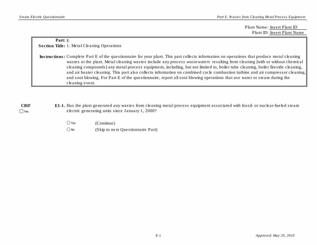
Steam Electric Questionnaire Part E. Wastes from Cleaning Metal Process Equipment
Plant Name: Insert Plant ID
Plant ID: Insert Plant Name
Part: E
Section Title:
Instructions:
CBI? E1-1.
(Continue)
(Skip to next Questionnaire Part)
1. Metal Cleaning Operations
Complete Part E of the questionnaire for your plant. This part collects information on operations that produce metal cleaning
wastes at the plant. Metal cleaning wastes include any process wastewaters resulting from cleaning [with or without chemical
cleaning compounds] any metal process equipment, including, but not limited to, boiler tube cleaning, boiler fireside cleaning,
and air heater cleaning. This part also collects information on combined cycle combustion turbine and air compressor cleaning,
and soot blowing. For Part E of the questionnaire, report all soot blowing operations that use water or steam during the
cleaning event.
Has the plant generated any wastes from cleaning metal process equipment associated with fossil- or nuclear-fueled steam
electric generating units since January 1, 2000?Yes
Yes
No
E-1 Approved: May 20, 2010

Steam Electric Questionnaire Part E. Wastes from Cleaning Metal Process Equipment
Plant Name:
Plant ID:
SE Unit ID:
Part: E
Section Title:
Instructions:
CBI? E2-1.
Does Type of
Cleaning Occur
at the Plant?
Typical Dose
Concentration
for Each
Chemical
(Grams per
Liter)
Other (specify):
Other (specify):
Other (specify):
Other (specify):
Other (specify):
Other (specify):
Other (specify):
Other (specify):
Other (specify):
Other (specify):
Other (specify):
Other (specify):
Insert Plant ID
Insert Plant Name
Insert Unit ID
2. Generating Unit Cleaning Data
Typical Frequency of
Cleaning Events (e.g., 1
time every 3 years)
Table E-1. Metal Process Equipment Cleaning Operations Using Chemicals Performed on Steam Electric Generating Units
In Table E-1, provide information about a typical cleaning event for each type of cleaning operation that uses chemical compounds on metal process equipment associated with fossil- or nuclear-fueled steam electric
generating units. In addition, please note whether or not each type of cleaning operation occurs at the plant.
NOTE: “Typical Dose Concentration” refers to the average concentration of the chemical within the cleaning water and "cleaning event" refers to one instance in which the plant performs a cleaning operation
on metal process equipment.
Complete Section 2 (Questions E2-1 and E2-2) for each fossil- or nuclear-fueled steam electric generating unit for which the plant has performed at least one cleaning operation on metal process equipment since January 1,
2000. See Part A Section 8 for unit classifications. Enter the steam electric generating unit ID under the section heading above (use steam electric generating unit IDs assigned in Table A-8). Make a copy of Section 2 for
each steam electric generating unit identified in Table A-8 using the "Copy Section 2" button below. Please provide all free response answers in the highlighted yellow areas.
NOTE: Combined cycle systems are considered steam electric generating units and, therefore, any cleaning operations performed on ANY portion of a combined cycle system, including cleaning operations
associated with the combustion turbine portion of the system should be reported in this part. When responding to these questions, provide answers that describe the typical cleaning operation for the steam
electric generating unit.
Type of Metal Cleaning
OperationOperation ID
Typical
Amount
Added for
Each
Chemical per
Cleaning
Event
(Gallons)
Type of Water Used in Cleaning
Operation
Typical Volume
of Metal
Cleaning Waste
Generated per
Cleaning Event
(Gallons)
Chemical Addition
Type of Chemical Used in
Operation
Other (specify):
Other (specify):
Other (specify):
yrs
yrs
Boiler tube cleaningTUBE_CHEM
time(s)
every
time(s)
every
Other (specify):
FIRE_CHEM Boiler fireside cleaning
Other (specify):
Other (specify):
Type of Water
Copy Section 2
Type of Water
Type of Water
Process Equipment Cleaning Chemical
Process Equipment Cleaning Chemical
Process Equipment Cleaning Chemical
Yes
Process Equipment Cleaning Chemical
Process Equipment Cleaning Chemical
Process Equipment Cleaning Chemical
Type of Water
Type of Water
Type of Water
Process Equipment Cleaning Chemical
Process Equipment Cleaning Chemical
Process Equipment Cleaning Chemical
Process Equipment Cleaning Chemical
Process Equipment Cleaning Chemical
Process Equipment Cleaning Chemical
Yes
No
Yes
No
E-2 Approved: May 20, 2010

Steam Electric Questionnaire Part E. Wastes from Cleaning Metal Process Equipment
Other (specify):
Other (specify):
Other (specify):
Other (specify):
Other (specify):
Other (specify):
Other (specify):
Other (specify):
Other (specify):
Other (specify):
Other (specify):
Other (specify):
Other (specify):
Other (specify):
Other (specify):
Other (specify):
Other (specify):
Other (specify):
yrs
yrs
yrs
SOOT_CHEM Soot blowing
AIR_CHEM Air heater cleaning
time(s)
every
time(s)
every
time(s)
every
Other (specify):
Other (specify):
Other (specify):
Other (specify):
Other (specify):
Other (specify):
Other (specify):
Other (specify):
Other (specify):
ST-TURB_CHEM Steam turbine cleaning
Type of Water
Type of Water
Type of Water
Process Equipment Cleaning Chemical
Process Equipment Cleaning Chemical
Process Equipment Cleaning Chemical
Process Equipment Cleaning Chemical
Process Equipment Cleaning Chemical
Process Equipment Cleaning Chemical
Type of Water
Type of Water
Type of Water
Process Equipment Cleaning Chemical
Process Equipment Cleaning Chemical
Process Equipment Cleaning Chemical
Process Equipment Cleaning Chemical
Process Equipment Cleaning Chemical
Process Equipment Cleaning Chemical
Type of Water
Type of Water
Type of Water
Process Equipment Cleaning Chemical
Process Equipment Cleaning Chemical
Process Equipment Cleaning Chemical
Process Equipment Cleaning Chemical
Process Equipment Cleaning Chemical
Process Equipment Cleaning Chemical
Yes
No
Yes
No
Yes
No
E-3 Approved: May 20, 2010

Steam Electric Questionnaire Part E. Wastes from Cleaning Metal Process Equipment
Other (specify):
Other (specify):
Other (specify):
Other (specify):
Other (specify):
Other (specify):
Other (specify):
Other (specify):
Other (specify):
Other (specify):
Other (specify):
Other (specify):
Other (specify):
Other (specify):
Other (specify):
Other (specify):
Other (specify):
Other (specify):
Other (specify):
Other (specify):
Other (specify):
Other (specify):
Other (specify):
Other (specify):
yrsOther (specify):
yrs
yrs
time(s)
every
time(s)
every
time(s)
every
time(s)
every
yrs
Other (specify):
Other (specify):
Other (specify):
Other (specify):
Other (specify):
Other (specify):
Other (specify):
Other (specify):
Other (specify):
Other (specify):
Other (specify):
CT-COMPR_CHEM Combustion turbine
cleaning (compressor
portion of combustion
turbine)
CT-COMB_CHEM Combustion turbine
cleaning (combustion
portion of turbine)
Other Other:
Other Other:
Type of Water
Type of Water
Type of Water
Process Equipment Cleaning Chemical
Process Equipment Cleaning Chemical
Process Equipment Cleaning Chemical
Process Equipment Cleaning Chemical
Process Equipment Cleaning Chemical
Process Equipment Cleaning Chemical
Type of Water
Type of Water
Type of Water
Process Equipment Cleaning Chemical
Process Equipment Cleaning Chemical
Process Equipment Cleaning Chemical
Process Equipment Cleaning Chemical
Process Equipment Cleaning Chemical
Process Equipment Cleaning Chemical
Type of Water
Type of Water
Type of Water
Process Equipment Cleaning Chemical
Process Equipment Cleaning Chemical
Process Equipment Cleaning Chemical
Process Equipment Cleaning Chemical
Process Equipment Cleaning Chemical
Process Equipment Cleaning Chemical
Type of Water
Type of Water
Type of Water
Process Equipment Cleaning Chemical
Process Equipment Cleaning Chemical
Process Equipment Cleaning Chemical
Process Equipment Cleaning Chemical
Process Equipment Cleaning Chemical
Process Equipment Cleaning Chemical
Yes
No
Yes
No
Yes
No
Yes
No
E-4 Approved: May 20, 2010

Steam Electric Questionnaire Part E. Wastes from Cleaning Metal Process Equipment
CBI? E2-2.
Other (specify):
yrs
Other (specify):
Other (specify):
Other (specify):
yrs
Other (specify):
Other (specify):
Other (specify):
yrs
Other (specify):
Other (specify):
Table E-2. Metal Process Equipment Cleaning Operations Without Chemicals
Performed on Steam Electric Generating Units
Operation ID
Type of Metal Cleaning
Operation
Type of Water Used in Cleaning
Operation
TUBE_NO_CHEM Boiler tube cleaning
FIRE_NO_CHEM Boiler fireside cleaning
AIR_NO_CHEM Air heater cleaning
In Table E-2, provide information about a typical cleaning event for each type of cleaning operation that does not use chemical compounds on metal process equipment associated with fossil- or nuclear- fueled steam electric
generating units. In addition, please note whether or not each type of cleaning operation occurs at the plant.
NOTE: “Typical Dose Concentration” refers to the average concentration of the chemical within the cleaning water and "cleaning event" refers to one instance in which the plant performs a cleaning operation
on metal process equipment.
Typical Frequency of Cleaning
Events (e.g., 1 time every 3
years)
time(s)
every
time(s)
every
time(s)
every
Typical Volume
of Metal
Cleaning Waste
Generated per
Cleaning Event
(Gallons)
Does Type of
Cleaning Occur
at the Plant?
Type of Water
Type of Water
Type of Water
Type of Water
Type of Water
Type of Water
Type of Water
Type of Water
Type of Water
Yes
Yes
No
Yes
No
Yes
No
Type of Water
Type of Water
Type of Water
Type of Water
Type of Water
Type of Water
E-5 Approved: May 20, 2010

Steam Electric Questionnaire Part E. Wastes from Cleaning Metal Process Equipment
Other (specify):
yrs
Other (specify):
Other (specify):
Other (specify):
yrs
Other (specify):
Other (specify):
Other (specify):
yrs
Other (specify):
Other (specify):
Other (specify):
yrs
Other (specify):
Other (specify):
Other (specify):
yrs
Other (specify):
Other (specify):
Other (specify):
yrs
Other (specify):
Other (specify):
SOOT_NO_CHEM Soot blowing
Other Other:
ST-TURB_NO_CHEM Steam turbine cleaning
CT-COMB_NO_CHEM Combustion turbine
cleaning (combustion
portion of turbine)
CT-
COMPR_NO_CHEM
Combustion turbine
cleaning (compressor
portion of combustion
turbine)
Other Other:
time(s)
every
time(s)
every
time(s)
every
time(s)
every
time(s)
every
time(s)
every
Type of Water
Type of Water
Type of Water
Type of Water
Type of Water
Type of Water
Type of Water
Type of Water
Type of Water
Type of Water
Type of Water
Type of Water
Type of Water
Type of Water
Type of Water
Type of Water
Type of Water
Type of Water
Yes
No
Yes
No
Yes
No
Yes
No
Yes
No
Yes
No Type of Water
Type of Water
Type of Water
Type of Water
Type of Water
Type of Water
Type of Water
Type of Water
Type of Water
Type of Water
Type of Water
Type of Water
E-6 Approved: May 20, 2010

Steam Electric Questionnaire Part E. Wastes from Cleaning Metal Process Equipment
Plant Name: Insert Plant ID
Plant ID: Insert Plant Name
SE Unit ID: Insert Unit ID
Insert Operation ID
Part: E
Section Title:
Instructions:
CBI? E3-1.
Example: The plant uses citric acid to remove copper deposits and iron oxides from the steel tube surfaces of the boiler. The citric acid
is diluted to a pH of 3.5 and then used for cleaning in a two-stage process. In the first stage, the citric acid dissolves iron oxides. In the
second stage anhydrous ammonia is added to raise the pH of the cleaning solution between 9 and 10 and air is bubbled through the
solution to dissolve copper deposits.
Metal Cleaning Operation ID:
Complete Section 3 (Questions E3-1 through E3-8) for each type of metal cleaning operation performed on the steam electric
generating unit, which is identified in Tables E-1 and E-2 of Section 2. Make a copy of Section 3 using the "Copy Section 3" button
below. Enter the steam electric generating unit ID under the section heading above (use steam electric generating unit IDs assigned in
Table A-8). In addition, enter the metal cleaning operation ID performed on the steam electric generating unit (use the IDs from Tables
E-1 and E-2). Please provide all free response answers in the highlighted yellow areas.
In the space below, provide a description of the process equipment cleaning operation. Include the type of equipment and metal
cleaned, any chemical preparation steps (e.g., diluting the chemical prior to use), and a short description of the cleaning operation. An
example is provided below.
3. Cleaning Operation Data
Yes
Copy Section 3
E-7 Approved: May 20, 2010

Steam Electric Questionnaire Part E. Wastes from Cleaning Metal Process Equipment
CBI? E3-2.
CBI? E3-3.
CBI? E3-4.
(Continue)
Are residues or other solid by-products generated from the cleaning operation?
(Skip to next Questionnaire Part)
Is the cleaning waste commingled with other process wastewaters ? If yes, indicate the process wastewaters with which the metal
cleaning waste is commingled. [Check all boxes that apply.]
What is the destination(s) of the cleaning waste? If the plant recycles the waste, indicate the plant process to which this waste is
recycled. [Check all boxes that apply.]
Yes
Yes
Yes
Fly ash transport water
Bottom ash transport water
FGD scrubber purge
Cooling tower blowdown
Once through cooling water
Other:
Chemical precipitation
Constructed wetlands
pH adjustment Other, specify:
Immediately recycled back to plant process. Please describe how the cleaning waste is reused:
Transferred to on-site treatment system. Identify the type of treatment system below. [Check all boxes that apply.]
Discharged to surface water. Provide NPDES permitted outfall number (from Part A Section 2.2):
Indirect discharge to a publicly or privately owned treatment works
Other, explain:
Yes
No
Evaporated during a cleaning operation
Yes
No
Settling Pond
E-8 Approved: May 20, 2010

Steam Electric Questionnaire Part E. Wastes from Cleaning Metal Process Equipment
CBI? E3-5.
CBI? E3-6. Indicate what characteristic(s) make the waste hazardous.
CBI? E3-7.
tons per cleaning event
If residues are generated, indicate if they are considered always hazardous, sometimes hazardous, or non-hazardous waste.
tons per cleaning event
tons per cleaning event
tons per cleaning event
Indicate how the plant handles the residue or other solid by-products and provide the tons per cleaning event for each type of storage
handling technique. If the solid by-products are stored in a landfill or pond/impoundment , indicate whether the solid by-products are
stored permanently or temporarily. [Check all boxes that apply.]
(Skip to Question E3-7)
tons per cleaning event
tons per cleaning event
(Continue)
(Continue)
(Skip to Question E3-7)
Yes
Yes
Yes
Landfilled
Stored permanently
Stored temporarily (later hauled off-site)
Sent to a pond/impoundment
Stored permanently
Stored temporarily (later hauled off-site)
Hauled off-site for disposal
Other (specify):
Always hazardous
Unknown
Always non-hazardous
Sometimes hazardous
E-9 Approved: May 20, 2010

Steam Electric Questionnaire Part E. Wastes from Cleaning Metal Process Equipment
CBI? E3-8. If the plant stores the residues or other solid by-products from cleaning operations in a landfill or pond/impoundment, are they combined
with other solid by-products generated at the plant? If yes, indicate which. [Check all boxes that apply.]
Fly ash
Bottom ash
FGD solids
Mill rejects
Other:
Yes
Yes
No (residues/solid by-products transferred to landfill but not combined with other wastes)
NA (residues/solid by-products not transferred to landfill or pond/impoundment)
E-10 Approved: May 20, 2010

Steam Electric Questionnaire Part E. Wastes from Cleaning Metal Process Equipment
Plant ID: Insert Plant IDPlant Name: Insert Plant Name
Part: ESection Title: Part E Comments
Instructions:
Question
Number
CBI?
CBI?
CBI?
CBI?
CBI?
CBI?
CBI?
CBI?
CBI?
CBI?
CBI?
Cross reference your comments by question number and indicate the confidential status of your comment by checking the box
next to “Yes” under "CBI?" (Confidential Business Information).
Comment
Yes
Yes
Yes
Yes
Yes
Yes
Yes
Yes
Yes
Yes
Yes
E-11 Approved: May 20, 2010

Steam Electric Questionnaire Part E. Wastes from Cleaning Metal Process Equipment
CBI?
CBI?
CBI?
CBI?
CBI?
CBI?
CBI?
CBI?
CBI?
CBI?
CBI?
CBI?
CBI?
CBI?
CBI?
Yes
Yes
Yes
Yes
Yes
Yes
Yes
Yes
Yes
Yes
Yes
Yes
Yes
Yes
Yes
E-12 Approved: May 20, 2010
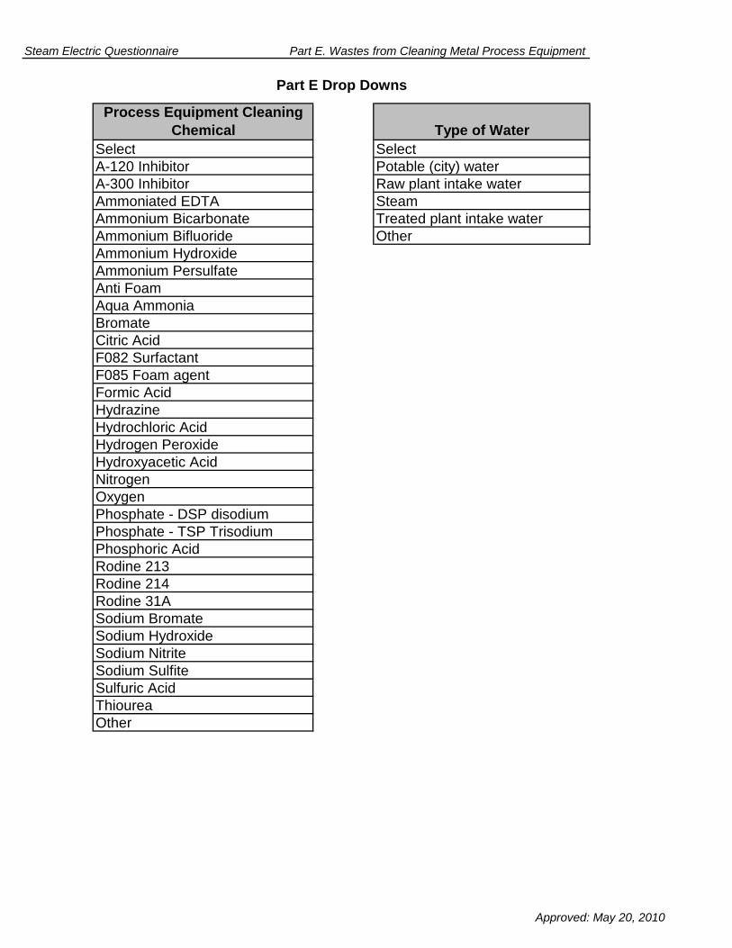
Steam Electric Questionnaire Part E. Wastes from Cleaning Metal Process Equipment
Process Equipment Cleaning
Chemical Type of Water
Select Select
A-120 Inhibitor Potable (city) water
A-300 Inhibitor Raw plant intake water
Ammoniated EDTA Steam
Ammonium Bicarbonate Treated plant intake water
Ammonium Bifluoride Other
Ammonium Hydroxide
Ammonium Persulfate
Anti Foam
Aqua Ammonia
Bromate
Citric Acid
F082 Surfactant
F085 Foam agent
Formic Acid
Hydrazine
Hydrochloric Acid
Hydrogen Peroxide
Hydroxyacetic Acid
Nitrogen
Oxygen
Phosphate - DSP disodium
Phosphate - TSP Trisodium
Phosphoric Acid
Rodine 213
Rodine 214
Rodine 31A
Sodium Bromate
Sodium Hydroxide
Sodium Nitrite
Sodium Sulfite
Sulfuric Acid
Thiourea
Other
Part E Drop Downs
Approved: May 20, 2010

OMB Control Number: 2040-0281 Plant ID: Insert Plant ID
Approval Expires: 05/31/2013 Plant Name: Insert Plant Name
Tab Name
Part F Instructions Part F Instructions
Part F Section 1
Part F Section 2
Part F Section 3.1
Part F Section 3.2
Part F Section 4.1
Part F Section 4.2
Part F Section 4.3
Part F Section 4.4
Part F Section 4.5
Part F Section 4.6
Part F Section 5
Part F Comments
Code TablesSteam Electric Questionnaire Code Tables
Pond/Impoundment and Landfill Use
Groundwater Monitoring Practices
Leachate Treatment System Units
Leachate Treatment Unit Information
Pond/Impoundment Management Practices
Part F Comments
Landfill Management Practices
Leachate Treatment System Design
Leachate Treatment System Flows
Leachate Treatment System Costs
Leachate Treatment System Equipment
Landfill Costs
Steam Electric Questionnaire
PART F - MANAGEMENT PRACTICES FOR PONDS/IMPOUNDMENTS AND LANDFILLS
Table of Contents
Section Title
Approved: May 20, 2010

Steam Electric Questionnaire Part F. Instructions
Plant ID: Insert Plant ID
Plant Name: Insert Plant Name
PART F. MANAGEMENT PRACTICES FOR PONDS/IMPOUNDMENTS AND
LANDFILLS
Throughout Part F Section 4, information is requested on leachate treatment units and
systems that are planned, under construction/installation, or planned to begin
construction/installation by December 31, 2020. Provide design information, or best
engineering estimates as necessary, for these planned systems/units. Additionally, enter
“NA” in the field or checkbox if the information requested is not applicable for planned
systems/units (e.g., a question that requests flow rate data for year 2009).
Use the Part F Comments tab to do the following: provide additional information as
requested in certain questions within Part F; indicate atypical data (e.g., if 2009
information is not representative of normal operations); and note methods used to make
best engineering estimates in the event that exact data are not available.
INSTRUCTIONS
Complete Part F of the questionnaire for your plant. As you are completing the electronic
form, note the following: When you enter your plant name and plant ID on the Part F
TOC tab, all name and ID fields throughout Part F will automatically populate. Refer to
the overall questionnaire instructions, the glossary, and the acronym list for assistance
with completing Part F.
Please provide all free response answers in the highlighted yellow areas. Throughout
Part F, you may need to make copies of certain sections/questions. Instructions are
provided throughout Part F regarding making copies. Note that pond/impoundment unit,
landfill, leachate treatment system, and leachate treatment unit names or IDs must be
populated on the copied tab or section, located in the upper right corner under "Plant ID"
and "Plant Name", in order to correlate the requested information.
Approved: May 20, 2010

Steam Electric Questionnaire Part F. Management Practices for Ponds/Impoundments and Landfills
Insert Plant ID
Insert Plant Name
Part:
Section Title:
Instructions:
CBI? F1-1.
Part F requests information for all active/inactive/open and retired/closed pond/impoundment units and landfills ,
including those located on non-adjoining property, used for the storage, treatment, and/or disposal of process
wastewater , residues , or by-products (or sludges or water streams containing the residues or by-products) from the
combustion of coal or petroleum coke, including, but not limited to, fly ash , bottom ash , boiler slag, or flue gas emission
control residues. This includes liquid-borne material and solid material.
Does the plant have one or more active/inactive/open or retired/closed pond/impoundment units or landfills , including
those located on non-adjoining property, used for the storage, treatment, and/or disposal of process wastewater,
residues, or by-products (or sludges or water streams containing the residues or by-products) from the combustion of
coal or petroleum coke, including, but not limited to, fly ash, bottom ash, boiler slag, or flue gas emission control residues
(this includes liquid-borne material and solid material)? [Check the box below.]
Note: Answer "yes" to this question even if all the pond/impoundments and landfills are closed.
(Continue)
(Skip to the next Questionnaire Part)
Plant ID:
Plant Name:
F
1. Pond/Impoundment and Landfill Use
Yes
No
Yes
F-1 Approved: May 20, 2010

Steam Electric Questionnaire Part F. Management Practices for Ponds/Impoundments and Landfills
Plant ID: Insert Plant ID
Plant Name: Insert Plant Name
Pond/Impoundment Unit ID: Insert Pond ID
Part:
Section Title:
Instructions:
CBI? F2-1.
2. Pond/Impoundment Management Practices
F
If known, indicate the hydrologic design criteria of the pond/impoundment unit.
Pond/Impoundment Unit Design
Complete Section 2 for each active/inactive/open and retired/closed pond/impoundment unit, including those
located on non-adjoining property, used for the storage, treatment, and/or disposal of process wastewater ,
residues , or by-products (or sludges or water streams containing the residues or by-products) from the
combustion of coal or petroleum coke, including, but not limited to, fly ash , bottom ash , boiler slag, or flue gas
emission control residues. This includes liquid-borne material and solid material. Enter the pond/impoundment
unit ID in the space provided above (use pond/impoundment unit IDs assigned in Table A-4). Please provide all
free response answers in the highlighted yellow areas.
Make a copy of Section 2 for each active/inactive/open and retired/closed pond/impoundment unit, including
those located on non-adjoining property, using the "Copy Section 2" button below.
Copy Section 2
Yes
None
Other (specify):
½ Probable maximum flood
100-year, 24-hour storm event
F-2 Approved: May 20, 2010

Steam Electric Questionnaire Part F. Management Practices for Ponds/Impoundments and Landfills
CBI? F2-2.
CBI? F2-3.
CBI? F2-4.
(Skip to Question F2-4)
Leachate Collection and Leak Detection Systems
Has the pond/impoundment unit ever experienced an overflow or other type of release, excluding routine
permitted discharges , since January 1,1995?
State when the overflow occurred and describe the reason for the
overflow (e.g., experienced two 100-year, 24-hour storm events within
one month):
Has a non-permitted pond/impoundment overflow or other type of release been discharged to a receiving water,
since January 1, 1995? If so, identify the name of the receiving water.
Does the pond/impoundment unit have a system to collect leachate (including leaks, seepage, toe drains, or
similar releases)?
(Skip to Question F2-9)
No
Yes
No
Yes
Yes
Yes
Yes
Yes (specify name of receiving water):
No
Leachate collection system
Leak detection system
Other collection system (specify):
F-3 Approved: May 20, 2010

Steam Electric Questionnaire Part F. Management Practices for Ponds/Impoundments and Landfills
CBI? F2-5.
gpdANDgpy Over
CBI? F2-6.
gpy
gpy
gpy
If other, explain:
Does the plant collect stormwater, rainfall, or process wastewaters in the collection system for this
pond/impoundment unit? If yes, identify the stormwater, rainfall, or process wastewaters and their flow rates. If the
process wastewater is not one of the response options provided, select "Other" in the drop-down box and specify
the type of process wastewater in the yellow highlighted space below.
days
Provide the volume of leachate (including leaks, seepage, toe drains, or similar releases) collected in 2009 (gpd
AND gpy) and the frequency of process wastewater generation (days). Also provide a description of the
estimation method below.
Description of estimation method:
Yes
Yes
Yes
No
Uncontaminated stormwater
Rainfall
Process Wastewaters 2
F-4 Approved: May 20, 2010

Steam Electric Questionnaire Part F. Management Practices for Ponds/Impoundments and Landfills
CBI? F2-7.
CBI? F2-8. If the leachate is sent to a pond or storage tank, are chemicals used to treat the leachate (e.g., lime for pH
control)? If yes, indicate which chemicals are used. [Check all boxes that apply].
Indicate all intermediate and final destination(s) of the leachate. If the plant recycles the leachate, indicate the
plant process to which this waste is recycled. [Check all boxes that apply.]
Is this wastewater treatment system previously defined in Table D-2?
Transferred back into pond/impoundment unit
Combined with pond/impoundment unit effluent
Transferred to other pond/impoundment units. Provide ID of the pond/impoundment unit previously defined in Table A-4:
Transferred to on-site treatment system, including those located on non-adjoining property.
Transferred back to storage tank
Discharged to surface water. Provide NPDES permitted outfall number (from Part A Section 2.2):
Other, explain:
Lime
Sodium Hydroxide
Sulfuric Acid
Other (specify):
Yes
Yes
Yes (specify the wastewater treatment system ID from Table D-2):
No (section 4 of Part F must be filled out for this treatment system)
Immediately recycled back to plant process. Please describe how the leachate is reused:
Indirect discharge to a publicly or privately owned treatment works
Yes
No
NA
F-5 Approved: May 20, 2010

Steam Electric Questionnaire Part F. Management Practices for Ponds/Impoundments and Landfills
CBI? F2-9.
(Continue)
CBI? F2-10.
Inspections/year hrs/year
Inspections/year hrs/year
Inspections/year hrs/year
Inspections/year hrs/year
Inspections/year hrs/year
Inspections/year hrs/year
Inspections/year hrs/year
Inspections/year hrs/year
Indicate which of the following monitoring measures or inspections are performed on the pond/impoundment unit
by the plant and/or its engineering contractors, the frequency of monitoring, and the average number of hours
spent each year performing monitoring activities:
(Skip to Section 3)
Monitoring and Inspections
Does the plant and/or its engineering contractors regularly monitor/inspect the structural integrity of the
pond/impoundment unit?
Yes
No
Yes
Yes
Seepage
Piezometric levels
Pool levels (indication of rapid drawdown)
Spillway/weir/outflow structural integrity
Other (specify):
Deformation/movement of dike/embankment
Compaction testing
Other (specify):
F-6 Approved: May 20, 2010
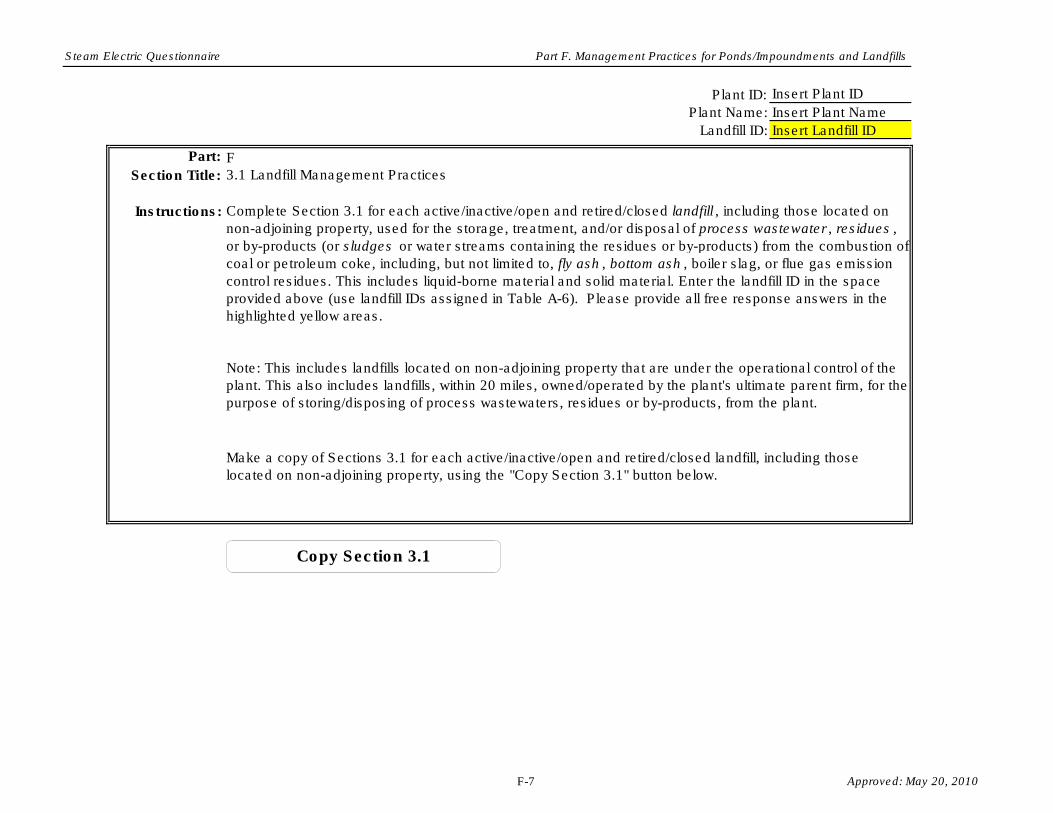
Steam Electric Questionnaire Part F. Management Practices for Ponds/Impoundments and Landfills
Plant ID:
Part: F
Section Title:
Instructions: Complete Section 3.1 for each active/inactive/open and retired/closed landfill , including those located on
non-adjoining property, used for the storage, treatment, and/or disposal of process wastewater , residues ,
or by-products (or sludges or water streams containing the residues or by-products) from the combustion of
coal or petroleum coke, including, but not limited to, fly ash , bottom ash , boiler slag, or flue gas emission
control residues. This includes liquid-borne material and solid material. Enter the landfill ID in the space
provided above (use landfill IDs assigned in Table A-6). Please provide all free response answers in the
highlighted yellow areas.
Make a copy of Sections 3.1 for each active/inactive/open and retired/closed landfill, including those
located on non-adjoining property, using the "Copy Section 3.1" button below.
Note: This includes landfills located on non-adjoining property that are under the operational control of the
plant. This also includes landfills, within 20 miles, owned/operated by the plant's ultimate parent firm, for the
purpose of storing/disposing of process wastewaters, residues or by-products, from the plant.
Insert Plant ID
Insert Plant Name
Insert Landfill ID
Plant Name:
Landfill ID:
3.1 Landfill Management Practices
Copy Section 3.1
F-7 Approved: May 20, 2010

Steam Electric Questionnaire Part F. Management Practices for Ponds/Impoundments and Landfills
CBI? F3-1.
Date built
Surface area, acres
Volume capacity, cubic feet
Approved/licensed height, feet
CBI? F3-2.
Height above original elevation, feet
CBI? F3-3.
Height above original elevation, feet
Surface area, acres
Volume of stored materials, cubic feet
List the date the landfill was built, and the landfill’s surface area and approved/licensed volume capacity
and height when it was originally built.
Is the landfill closed? If yes, provide the date it was closed. If not, list the year of the landfill’s expected end
of life (i.e., closure), and the expected surface area, and volume and height of stored materials at its
expected end of life.
Surface area, acres
List the landfill’s current surface area, and volume, and height above the original elevation of the stored
materials.
Volume of stored materials, cubic feet
Yes. Date closed:
No. Year of expected end of life (closure):
Yes
Yes
Yes
F-8 Approved: May 20, 2010
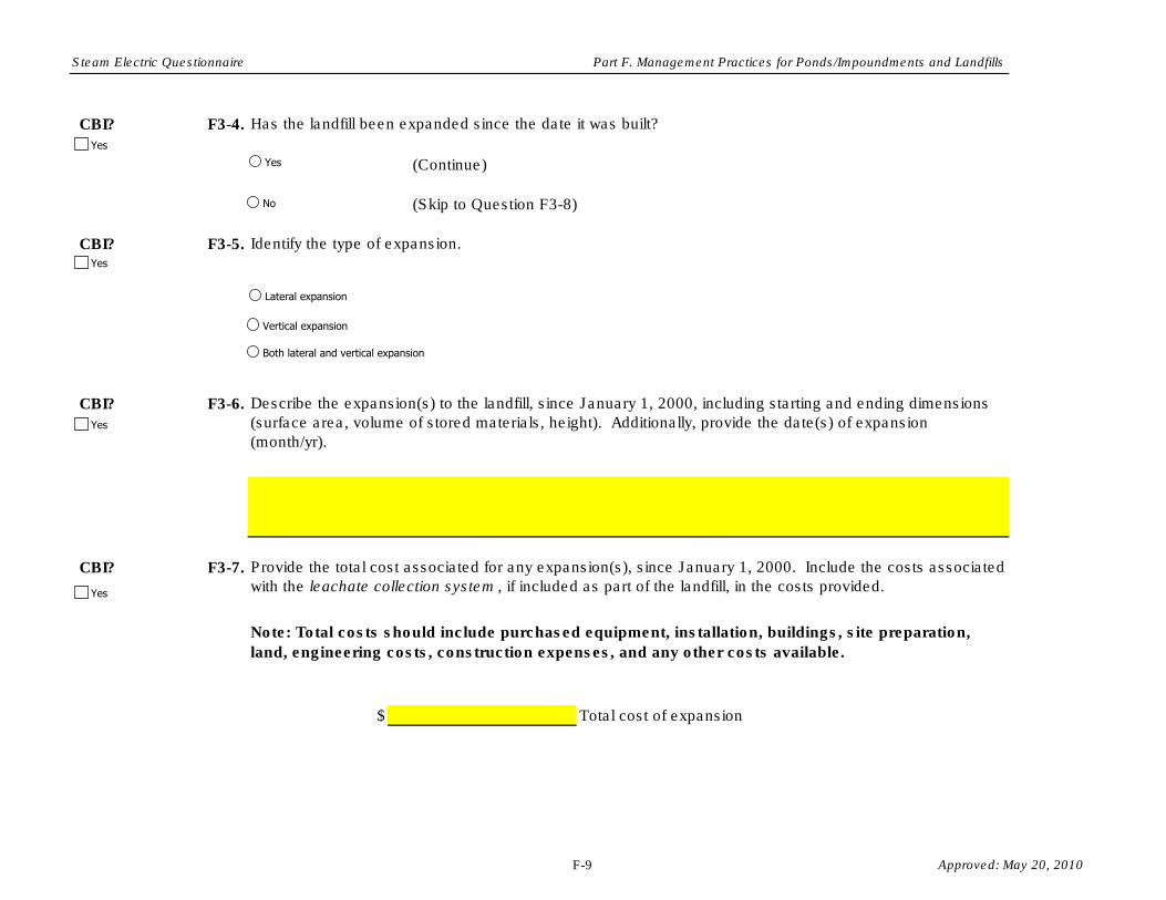
Steam Electric Questionnaire Part F. Management Practices for Ponds/Impoundments and Landfills
CBI? F3-4.
(Continue)
CBI? F3-5.
CBI? F3-6.
CBI? F3-7.
$
(Skip to Question F3-8)
Total cost of expansion
Has the landfill been expanded since the date it was built?
Identify the type of expansion.
Describe the expansion(s) to the landfill, since January 1, 2000, including starting and ending dimensions
(surface area, volume of stored materials, height). Additionally, provide the date(s) of expansion
(month/yr).
Note: Total costs should include purchased equipment, installation, buildings, site preparation,
land, engineering costs, construction expenses, and any other costs available.
Provide the total cost associated for any expansion(s), since January 1, 2000. Include the costs associated
with the leachate collection system , if included as part of the landfill, in the costs provided.
Yes
No
Lateral expansion
Vertical expansion
Both lateral and vertical expansion
Yes
Yes
Yes
Yes
F-9 Approved: May 20, 2010

Steam Electric Questionnaire Part F. Management Practices for Ponds/Impoundments and Landfills
CBI? F3-8.
Liner Layer
Number
(number from
inner to outer
layer)
Permeability of
Liner Layer
(cm/sec)
Table F-1. Landfill Liner
Type of Liner (Mark all that apply)
Thickness of Liner
Layer (cm)
(Complete Table F-1)
(Skip to Question F3-9)
Does the landfill have a liner ?
Compacted clay
Geosynthetic clay
High density polyethylene (HDPE)
Other (specify)
Other (specify)
Other (specify)
Yes
Yes
No
F-10 Approved: May 20, 2010

Steam Electric Questionnaire Part F. Management Practices for Ponds/Impoundments and Landfills
CBI? F3-9.
Cap/Cover
Layer Number
(number from
inner to outer
layer)
CBI? F3-10. Has the plant built any structures on top of the closed landfill?
Provide a description of the structure(s) and any challenges that the plant faced building on top of the
landfill.
(Skip to Question F3-11)
(Skip to Question F3-11)
(Skip to Question F2-10)
Type of Cap/Cover (Mark all that apply)
Thickness of
Cap/Cover Layer
(cm)
Permeability of
Cap/Cover Layer
(cm/sec)
Does the landfill have a cap/cover?
Table F-2. Landfill Cap/Cover
(Complete Table F-2)
(Continue)
Yes
Compacted clay
Geosynthetic clay
High density polyethylene (HDPE)
Vegetative cover
Other (specify)
Other (specify)
Other (specify)
Yes
Yes
No
NA. The landfill is not closed.
Yes
No
F-11 Approved: May 20, 2010

Steam Electric Questionnaire Part F. Management Practices for Ponds/Impoundments and Landfills
Leachate Collection System
CBI? F3-11.
CBI? F3-12.
gpdANDgpy Over days
CBI? F3-13.
gpd
gpd
gpd
If other, explain:
(Skip to Question F3-16)
Does the plant collect stormwater, rainfall, or process wastewaters in the collection system for this landfill?
If yes, identify the stormwater, rainfall, or process wastewaters and their flow rates. If the process
wastewater is not one of the response options provided, select "Other" in the drop-down box and specify
the type of process wastewater in the yellow highlighted space below.
Provide the volume of leachate collected in 2009 (gpd AND gpy) and the frequency of process wastewater
generation (days). Also provide a description of the estimation method below.
Does the landfill have a system to collect leachate (including leaks, seepage, toe drains, or similar
releases)?
Description of estimation method:
Yes
Yes
Leachate collection system
Leak detection system
Other collection system (specify):
Yes
Yes
No
Uncontaminated stormwater
Rainfall
Process Wastewaters 2
Yes
No
F-12 Approved: May 20, 2010
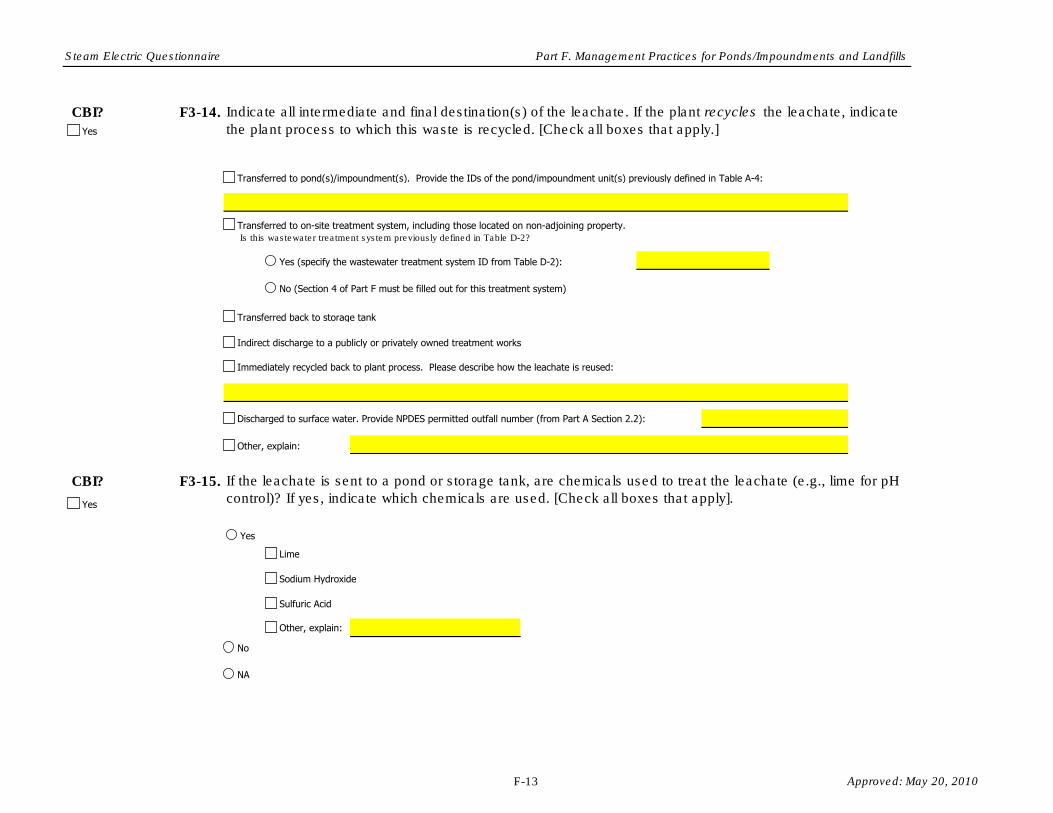
Steam Electric Questionnaire Part F. Management Practices for Ponds/Impoundments and Landfills
CBI? F3-14.
CBI? F3-15. If the leachate is sent to a pond or storage tank, are chemicals used to treat the leachate (e.g., lime for pH
control)? If yes, indicate which chemicals are used. [Check all boxes that apply].
Indicate all intermediate and final destination(s) of the leachate. If the plant recycles the leachate, indicate
the plant process to which this waste is recycled. [Check all boxes that apply.]
Is this wastewater treatment system previously defined in Table D-2?
Yes
Transferred to pond(s)/impoundment(s). Provide the IDs of the pond/impoundment unit(s) previously defined in Table A-4:
Transferred to on-site treatment system, including those located on non-adjoining property.
Transferred back to storage tank
Discharged to surface water. Provide NPDES permitted outfall number (from Part A Section 2.2):
Other, explain:
Yes
No
Lime
Sulfuric Acid
Sodium Hydroxide
Other, explain:
Yes (specify the wastewater treatment system ID from Table D-2):
No (Section 4 of Part F must be filled out for this treatment system)
Indirect discharge to a publicly or privately owned treatment works
Immediately recycled back to plant process. Please describe how the leachate is reused:
Yes
NA
F-13 Approved: May 20, 2010

Steam Electric Questionnaire Part F. Management Practices for Ponds/Impoundments and Landfills
CBI? F3-16.
CBI? F3-17.
Does the plant combine the conveyed stormwater runoff that has contacted the uncapped portion of the
landfill with leachate?
Indicate the type of treatment system below. Provide the ID of the wastewater treatment system previously defined in Table D-2, otherwise enter
NA:
Indicate all intermediate and final destination(s) of the conveyed stormwater runoff that has contacted the
uncapped portion of the landfill. If the plant recycles the stormwater runoff, indicate the plant process to
which this waste is recycled. [Check all boxes that apply.]
Stormwater Runoff
Yes
No
Transferred to pond/impoundment unit(s). Provide the ID(s) of the pond/impoundment unit(s) previously defined in Table A-4:
Transferred to on-site treatment system, including those located on non-adjoining property.
Transferred to storage tank
Discharged to surface water. Provide NPDES permitted outfall number (from Part A Section 2.2):
Other, explain:
Chemical precipitation
Biological reactor - aerobic
Biological reactor - anoxic\anaerobic
Constructed wetlands
Other (specify):
Indirect discharge to a publicly or privately owned treatment works
Immediately recycled back to plant process. Please describe how the leachate is reused:
Yes
Yes
F-14 Approved: May 20, 2010

Steam Electric Questionnaire Part F. Management Practices for Ponds/Impoundments and Landfills
CBI? F3-18.
CBI? F3-19.
Indicate the type of treatment system below. Provide the ID of the wastewater treatment system previously defined in Table D-2, otherwise enter
NA:
Indicate all intermediate and final destination(s) of the conveyed stormwater runoff that has contacted the
capped portion of the landfill. If the plant recycles the stormwater runoff, indicate the plant process to which
this waste is recycled. [Check all boxes that apply.]
Does the plant combine the conveyed stormwater runoff that has contacted the capped portion of the
landfill with leachate?
Yes
No
Transferred to on-site treatment system, including those located on non-adjoining property.
Transferred to storage tank
Discharged to surface water. Provide NPDES permitted outfall number (from Part A Section 2.2):
Other, explain:
Chemical precipitation
Biological reactor - aerobic
Biological reactor - anoxic\anaerobic
Constructed wetlands
Other (specify):
Indirect discharge to a publicly or privately owned treatment works
Immediately recycled back to plant process. Please describe how the leachate is reused:
Transferred to pond/impoundment unit(s). Provide the ID(s) of the pond/impoundment unit(s) previously defined in Table A-4:
Yes
Yes
F-15 Approved: May 20, 2010

Steam Electric Questionnaire Part F. Management Practices for Ponds/Impoundments and Landfills
Plant ID: Insert Plant ID
Plant Name: Insert Plant Name
Landfill ID: Insert System ID
Part: F
Section Title:
CBI? F3-20.
O&M Cost Category
No. of workers
Operating labor $ $ hpd
dpy
No. of workers
Maintenance labor $ $ hpd
dpy
Maintenance materials $
Chemicals $
Plants/organic matter $
Energy - Power for pumping $ $ per kWh kWh/hr
Energy - Power for operations other than pumping $ $ per kWh kWh/hr
3.2. Landfill Costs
Note: This includes landfills located on non-adjoining property that are under the operational control of the plant. This also includes landfills, within 20 miles, owned/operated by the plant's
ultimate parent firm, for the purpose of storing/disposing of process wastewaters, residues or by-products, from the plant.
Make a copy of Sections 3.2 for each active/inactive/open and retired/closed landfill, including those located on non-adjoining property, using the "Copy Section 3.2" button below.
Provide annual O&M cost data in Table F-3 for each landfill identified in Table A-6 that was operated in 2009. Provide best engineering estimates when actual data are not readily
available. If you provide an estimate, note the methods that were used to make the estimates in the Comments page.
Table F-3. O&M Cost for Landfills for 2009
Note: Do NOT include O&M costs for leachate treatment systems, as the information will be collected in Section 4.5.
2009 Annual Cost Rate Staffing/ Consumption
per hour (average
rate of labor)
per hour (average
rate of labor)
Instructions: Complete Section 3.2 for each active/inactive/open and retired/closed landfills that began operating at the plant on or after January 1, 2000. This includes landfills located on non-adjoining
property, used for the storage, treatment, and/or disposal of process wastewater, residues, or by-products (or sludges or water streams containing the residues or by-products) from the
combustion of coal or petroleum coke, including, but not limited to, fly ash, bottom ash, boiler slag, or flue gas emission control residues. This includes liquid-borne material and solid
material. Enter the landfill ID in the space provided above (use landfill IDs assigned in Table A-6). Please provide all free response answers in the highlighted yellow areas.
Yes
F-16 Approved: May 20, 2010

Steam Electric Questionnaire Part F. Management Practices for Ponds/Impoundments and Landfills
Steam $ $ per pound pounds/hr
Hazardous Sludge Disposal - Dredging $ $ per
Hazardous Sludge Disposal - Landfilling $ $ per
Nonhazardous Sludge Disposal - Dredging $ $ per
Nonhazardous Sludge Disposal - Landfilling $ $ per
Other:
$
Other:
$
Total O&M Cost (2009) $
CBI? F3-21. Provide capital cost data in Table F-4 for all landfills identified in Table A-6, including planned leachate treatment systems. Provide best engineering estimates when actual data are not
readily available. For all costs, do not adjust for inflation. For example, if the plant incurred a land cost in 2002, enter the cost in the “Cost” column and enter “2002” in the “Year on which
Cost is Based” column.
Note: If no records are available on this leachate treatment system, provide an explanation in the Comments page.
Note: Do NOT include capital costs for leachate treatment systems, as the information will be collected in Section 4.5.
Gal
Ton
Gal
Ton
Gal
Ton
Gal
Ton
Yes
F-17 Approved: May 20, 2010

Steam Electric Questionnaire Part F. Management Practices for Ponds/Impoundments and Landfills
Project
$
$
$
$
$
Total Direct Costs $
a. Engineering Contract Firm Costs $
b. Owner's Overhead Engineering Costs $
$
$
$
Total Indirect Costs $
Total Capital Cost $
Table F-4. Capital Cost for Landfills
Cost Year on which Cost is
Based
Direct Costs
Purchased equipment (includes all equipment for the installation or
the upgrade: mechanical equipment; piping; instrumentation;
electrical equipment; plants/organic matter for constructed
wetland(s); spare parts; freight charges; taxes; insurance; and
duties)
Purchased equipment installation (includes installation of all
equipment; piping; instrumentation/calibration; electrical equipment;
mechanical equipment; structural supports, insulation, and paint)
Buildings (buildings constructed to house operator rooms, or other
operations associated with the system; also includes plumbing,
heating, ventilation, dust collection, air conditioning, lighting,
telephones, intercoms, painting, sprinklers, fire alarms)
Site preparation (includes site clearing, all demolition, grading, roads,
walking areas, fences)
Land (includes property costs and survey fees)
Indirect Costs
Engineering Costs (includes process design and general
engineering, cost engineering, consulting fees, supervision,
inspection for each category below:
Construction expenses (includes temporary construction offices,
roads, communications, fencing; construction tools and equipment;
permits, taxes, insurance)
Other Contractor's Fees
Contingency actually expended (to compensate for unpredictable
events such as storms, floods, strikes, price changes, errors in
estimates, design changes, etc.)
Hired outside engineering firm to oversee design and/or installation of the treatment system.
F-18 Approved: May 20, 2010

Steam Electric Questionnaire Part F. Management Practices for Ponds/Impoundments and Landfills
Plant ID:
Plant Name:
Part: F
Section Title:
Instructions:
CBI? F4-1.
LTS
System
ID
Plant DesignationTreatment System
Footprint (ft2)
Year Initially
Brought On
Line
Number of Leachate
Collection Systems
Contributing to the
System
Distance from
Leachate Collection
System* (ft)
LTS-1 Outfall number:
Outfall number:
Outfall number:
Outfall number:
Outfall number:
Outfall number:
Outfall number:
Outfall number:
Outfall number:
* If there are multiple leachate collection systems transferring leachate to the treatment system, provide the average distance for all leachate collection systems.
LTS-A
4.1. Leachate Treatment System Design
Operating Leachate Treatment Systems
Complete Section 4.1 (Question F4-1and F4-2) for all leachate treatment systems (as specified in Question F2-7 and F3-14) which the plant operates or plans to operate or construct/install by December
31, 2020. Note that wastewater treatment systems previously defined in Table D-2 that receive pond/impoundment or landfill leachate should NOT be included in this table and you do not need to
provide information for those systems in this section. Refer to your responses to Questions F2-7 and F3-14 to identify the systems that need to be included in this table. Please provide all free response
answers in the highlighted yellow areas.
Approximate Distance
to Final Outfall (ft)
In Table F-5, list all leachate treatment systems (as specified in Question F2-7 and F3-14), not including wastewater treatment systems previously defined in Table D-2, which the plant operates or plans
to operate. For each leachate treatment system, EPA assigned a number (e.g., LTS-1, LTS-2) in Table F-5, which will be used throughout the remainder of the survey. In the “Plant Designation” column,
provide the plant’s name for each leachate treatment system. As an example, if a plant operates a chemical precipitation leachate treatment system that discharges to an ash pond/impoundment system,
the leachate treatment system should be identified in Table F-5 as LTS-1 and the ash pond/impoundment system should have been previously identified in Table D-1. For each planned leachate treatment
system, provide an estimate of the expected average annual flow rate of the effluent from the treatment system.
Table F-5. Plant Leachate Treatment Systems
LTS-2
LTS-3
LTS-4
LTS-5
LTS-6
Insert Plant ID
Insert Plant Name
LTS-B
Planned Leachate Treatment Systems
LTS-C
Yes
F-19 Approved: May 20, 2010
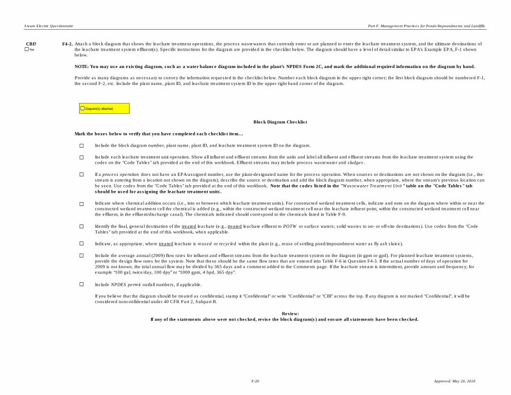
Steam Electric Questionnaire Part F. Management Practices for Ponds/Impoundments and Landfills
CBI? F4-2.
Include NPDES permit outfall numbers, if applicable.
If you believe that the diagram should be treated as confidential, stamp it "Confidential" or write "Confidential" or "CBI" across the top. If any diagram is not marked "Confidential", it will be
considered nonconfidential under 40 CFR Part 2, Subpart B.
Review:
If any of the statements above were not checked, revise the block diagram(s) and ensure all statements have been checked.
Block Diagram Checklist
Mark the boxes below to verify that you have completed each checklist item…
Include the block diagram number, plant name, plant ID, and leachate treatment system ID on the diagram.
Include each leachate treatment unit operation. Show all influent and effluent streams from the units and label all influent and effluent streams from the leachate treatment system using the
codes on the "Code Tables" tab provided at the end of this workbook. Effluent streams may include process wastewater and sludges .
If a process operation does not have an EPA-assigned number, use the plant-designated name for the process operation. When sources or destinations are not shown on the diagram (i.e., the
stream is entering from a location not shown on the diagram), describe the source or destination and add the block diagram number, when appropriate, where the stream's previous location can
be seen. Use codes from the "Code Tables" tab provided at the end of this workbook. Note that the codes listed in the "Wastewater Treatment Unit " table on the "Code Tables" tab
should be used for assigning the leachate treatment units.
Indicate where chemical addition occurs (i.e., into or between which leachate treatment units). For constructed wetland treatment cells, indicate and note on the diagram where within or near the
constructed wetland treatment cell the chemical is added (e.g., within the constructed wetland treatment cell near the leachate influent point, within the constructed wetland treatment cell near
the effluent, in the effluent/discharge canal). The chemicals indicated should correspond to the chemicals listed in Table F-9.
Indicate, as appropriate, where treated leachate is reused or recycled within the plant (e.g., reuse of settling pond/impoundment water as fly ash sluice).
Include the average annual (2009) flow rates for influent and effluent streams from the leachate treatment system on the diagram (in gpm or gpd). For planned leachate treatment systems,
provide the design flow rates for the system. Note that these should be the same flow rates that are entered into Table F-6 in Question F4-3. If the actual number of days of operation for
2009 is not known, the total annual flow may be divided by 365 days and a comment added to the Comments page. If the leachate stream is intermittent, provide amount and frequency; for
example “100 gal, twice/day, 100 dpy” or “1000 gpm, 4 hpd, 365 dpy”.
Attach a block diagram that shows the leachate treatment operations, the process wastewaters that currently enter or are planned to enter the leachate treatment system, and the ultimate destinations of
the leachate treatment system effluent(s). Specific instructions for the diagram are provided in the checklist below. The diagram should have a level of detail similar to EPA’s Example EPA_F-1 shown
below.
NOTE: You may use an existing diagram, such as a water balance diagram included in the plant’s NPDES Form 2C, and mark the additional required information on the diagram by hand.
Provide as many diagrams as necessary to convey the information requested in the checklist below. Number each block diagram in the upper right corner; the first block diagram should be numbered F-1,
the second F-2, etc. Include the plant name, plant ID, and leachate treatment system ID in the upper right hand corner of the diagram.
Identify the final, general destination of the treated leachate (e.g., treated leachate effluent to POTW or surface waters; solid wastes to on- or off-site destinations). Use codes from the "Code
Tables" tab provided at the end of this workbook, when applicable.
Diagram(s) attached.
Yes
F-20 Approved: May 20, 2010

Steam Electric Questionnaire Part F. Management Practices for Ponds/Impoundments and Landfills
Example EPA_F-1. Block Diagram for Leachate Treatment System
F-21 Approved: May 20, 2010

Steam Electric Questionnaire Part F. Management Practices for Ponds/Impoundments and Landfills
Plant ID:
Plant Name:
Leachate Treatment System ID:
Part: F
Section Title:
Instructions:
CBI? F4-3.
Insert Plant ID
Insert Plant Name
Insert System ID
Complete Section 4.2 (Question F4-3) for each leachate treatment system identified in Table F-5, including
planned systems, systems under construction/installation, or planned to be constructed/installed by December
31, 2020. Enter the leachate treatment system ID in the yellow highlighted space provided above (use the
leachate treatment system ID assigned in Table F-5).
Make a copy of Section 4.2 for each leachate treatment system identified in Table F-5 using the "Copy Section
4.2" button below.
4.2. Leachate Treatment System Flows
Complete Table F-6 for each leachate treatment system identified in Table F-5. Identify the process wastewaters
generated from pond/impoundment(s) and/or landfill(s), previously defined in Table A-4 and Table A-6, that are
treated by the leachate treatment system. Please provide the flow rates of the process wastewater into the
leachate treatment system. For planned leachate treatment systems, provide the design flow rates for the
system.
Yes
Copy Section 4.2
F-22 Approved: May 20, 2010
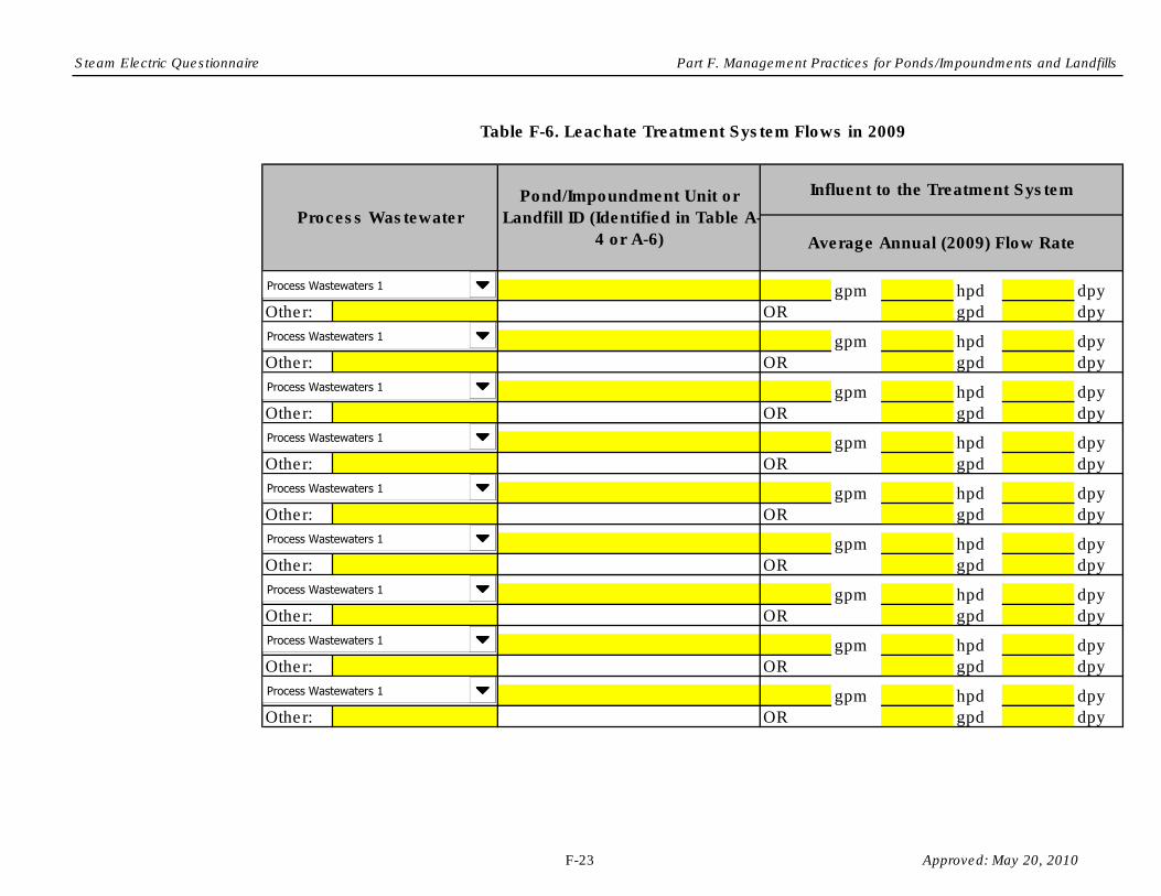
Steam Electric Questionnaire Part F. Management Practices for Ponds/Impoundments and Landfills
gpm hpd dpy
Other: OR gpd dpy
gpm hpd dpy
Other: OR gpd dpy
gpm hpd dpy
Other: OR gpd dpy
gpm hpd dpy
Other: OR gpd dpy
gpm hpd dpy
Other: OR gpd dpy
gpm hpd dpy
Other: OR gpd dpy
gpm hpd dpy
Other: OR gpd dpy
gpm hpd dpy
Other: OR gpd dpy
gpm hpd dpy
Other: OR gpd dpy
Pond/Impoundment Unit or
Landfill ID (Identified in Table A-
4 or A-6) Average Annual (2009) Flow Rate
Influent to the Treatment System
Process Wastewater
Table F-6. Leachate Treatment System Flows in 2009
Process Wastewaters 1
Process Wastewaters 1
Process Wastewaters 1
Process Wastewaters 1
Process Wastewaters 1
Process Wastewaters 1
Process Wastewaters 1
Process Wastewaters 1
Process Wastewaters 1
F-23 Approved: May 20, 2010

Steam Electric Questionnaire Part F. Management Practices for Ponds/Impoundments and Landfills
Plant ID: Insert Plant ID
Plant Name: Insert Plant Name
Leachate Treatment System ID: Insert System ID
Part: F
Section Title:
Instructions:
CBI? F4-4.
4.3. Leachate Treatment System Units
In Table F-7, list all leachate treatment units comprising the leachate treatment system including units that are operating, under
construction/installation, or planned to be constructed/installed by December 31, 2020. For each leachate treatment unit, assign an ID using the
leachate treatment unit ID options presented in the drop-down box; however, if a pond/impoundment unit is included as part of the leachate
treatment system, enter the pond/impoundment unit ID assigned in Table A-4 in the space labeled "Pond ID". The drop-down menu accounts for the
possibility of multiple leachate treatment system units; they are numbered sequentially. Note that these terms originated from the code tables on the
"Code Tables" tab, provided at the end of this workbook. For example, if the leachate treatment system includes two clarifiers, select Clarification,
Primary-1 for the first clarifier and Clarification, Secondary-1 for the second. In the “Plant Designation” column, provide the plant’s name for each
leachate treatment unit. In the “Date Added to WWT System” column, either enter the date the unit was/will be installed if the unit is a retrofit, or
enter “original” if the unit was part of the original wastewater treatment system installation.
Note: A constructed wetland cell is considered one leachate treatment unit.
Complete Section 4.3 (Questions F4-4 through F4-7) for each leachate treatment system identified in Table F-5, including systems that are planned,
under construction/installation, or planned to be constructed/installed by December 31, 2020. Enter the leachate treatment system ID in the yellow
highlighted space provided above (use leachate treatment system ID assigned in Table F-5).
Make a copy of Section 4.3 for each leachate treatment system identified in Table F-5 using the "Copy Section 4.3" button below.
NOTE: If the leachate treatment system includes a pond/impoundment unit, include the pond/impoundment unit in Table F-7.
Yes
F-24 Approved: May 20, 2010

Steam Electric Questionnaire Part F. Management Practices for Ponds/Impoundments and Landfills
Plant Designation
Other:
Pond ID:
Other:
Pond ID:
Other:
Pond ID:
Other:
Pond ID:
Other:
Pond ID:
Other:
Pond ID:
Other:
Pond ID:
Other:
Pond ID:
Other:
Pond ID:
Other:
Pond ID:
Other:
Pond ID:
Other:
Pond ID:
Leachate Treatment Unit ID
Table F-7. Leachate Treatment Units
Leachate Treatment Units
Leachate Treatment Units
Leachate Treatment Units
Leachate Treatment Units
Leachate Treatment Units
Leachate Treatment Units
Leachate Treatment Units
Leachate Treatment Units
Leachate Treatment Units
Leachate Treatment Units
Leachate Treatment Units
Leachate Treatment Units
F-25 Approved: May 20, 2010

Steam Electric Questionnaire Part F. Management Practices for Ponds/Impoundments and Landfills
CBI? F4-5.
Description of ImprovementExpected Date of Improvement
(mm/dd/yyyy)
Other: $
Pond ID:
Other: $
Pond ID:
Other: $
Pond ID:
Other: $
Pond ID:
Other: $
Pond ID:
Leachate Treatment Unit ID Total Capital Cost
In Table F-8, list all improvements to the leachate treatment system planned up to December 31, 2020. For each planned improvement to the
leachate treatment system, provide the appropriate Leachate Treatment Unit ID (if applicable), using the Code Tables. However, if the
improvement relates directly to a pond/impoundment, use the pond/impoundment ID assigned in Table A-4. Provide a description of the
improvement, the expected date of the improvement, and the total capital cost related to the improvement.
Note: Total capital costs should include purchased equipment, installation, buildings, site preparation, land, engineering costs,
construction expenses, and any other costs available.
Table F-8. Planned Improvements to the Leachate Treatment System
Yes
Leachate Treatment Units
Leachate Treatment Units
Leachate Treatment Units
Leachate Treatment Units
Leachate Treatment Units
F-26 Approved: May 20, 2010

Steam Electric Questionnaire Part F. Management Practices for Ponds/Impoundments and Landfills
CBI? F4-6.
(Provide further information)
(Skip to Question F4-7)
CBI? F4-7.
Typical flow rate in 2009, gpm
Maximum daily flow rate in 2009, gpd
Average annual flow rate in 2009, gpy
Duration of effluent transfers from treatment system in 2009, hpd
Frequency of effluent transfers from treatment system in 2009, dpy
Provide the typical flow rate for the leachate treatment system, the maximum flow rate for 2009, and the annual average flow rate for 2009. In
addition, provide the duration and frequency of the effluent transfers from the leachate treatment system in 2009. If the leachate treatment system is
planned, only provide the design flow rate and enter "N/A" in all other fields.
Were any of the above planned improvements to the leachate treatment system, or the planned leachate treatment system, planned in preparation
for potential limit changes in the future?
Please identify which pollutants and/or limits, in particular, the improvement or system will target.
Yes
Yes
Yes
No
F-27 Approved: May 20, 2010
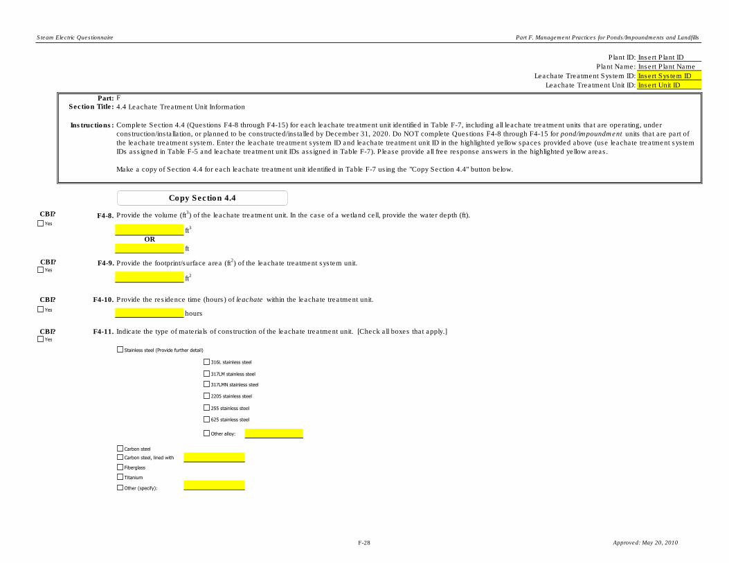
Steam Electric Questionnaire Part F. Management Practices for Ponds/Impoundments and Landfills
Plant ID: Insert Plant ID
Plant Name: Insert Plant Name
Leachate Treatment System ID: Insert System ID
Leachate Treatment Unit ID: Insert Unit ID
Part: F
Section Title:
Instructions:
CBI? F4-8.
ft3
OR
ft
CBI? F4-9.
ft2
CBI? F4-10.
hours
CBI? F4-11.
4.4 Leachate Treatment Unit Information
Provide the volume (ft3) of the leachate treatment unit. In the case of a wetland cell, provide the water depth (ft).
Complete Section 4.4 (Questions F4-8 through F4-15) for each leachate treatment unit identified in Table F-7, including all leachate treatment units that are operating, under
construction/installation, or planned to be constructed/installed by December 31, 2020. Do NOT complete Questions F4-8 through F4-15 for pond/impoundment units that are part of
the leachate treatment system. Enter the leachate treatment system ID and leachate treatment unit ID in the highlighted yellow spaces provided above (use leachate treatment system
IDs assigned in Table F-5 and leachate treatment unit IDs assigned in Table F-7). Please provide all free response answers in the highlighted yellow areas.
Make a copy of Section 4.4 for each leachate treatment unit identified in Table F-7 using the "Copy Section 4.4" button below.
Provide the footprint/surface area (ft2) of the leachate treatment system unit.
Indicate the type of materials of construction of the leachate treatment unit. [Check all boxes that apply.]
Provide the residence time (hours) of leachate within the leachate treatment unit.
Yes
Yes
Yes
Yes
Copy Section 4.4
Stainless steel (Provide further detail)
Carbon steel
Carbon steel, lined with
Fiberglass
Titanium
Other (specify):
316L stainless steel
317LM stainless steel
317LMN stainless steel
2205 stainless steel
255 stainless steel
625 stainless steel
Other alloy:
F-28 Approved: May 20, 2010

Steam Electric Questionnaire Part F. Management Practices for Ponds/Impoundments and Landfills
CBI? F4-12.
CBI? F4-13.
Pollutant:
Limitation:
Pollutant:
Limitation:
Pollutant:
Limitation:
Indicate the pollutants targeted for removal by this leachate treatment unit using techniques other than settling (e.g., adding chemicals to remove certain metals). [Check all boxes that
apply.]
Of the pollutants listed in Question F4-12, which effluent limitation(s) drives/will drive the operation of this leachate treatment unit? Provide the pollutant(s) and the limitation(s) (µg/L or
mg/L).
Metals (specify):
Mercury
Chlorides
Sulfates
TDS
TSS
Other:
Yes
Yes
Units
Units
Units
F-29 Approved: May 20, 2010

Steam Electric Questionnaire Part F. Management Practices for Ponds/Impoundments and Landfills
CBI? F4-14.
(Complete Table F-9)
Chemical Type Trade Name Manufacturer PurposeLocation of Chemical
Addition
Average Dose
Concentration
(g/L)
Frequency of
Addition (dpy)
CBI? F4-15.
(Complete Table F-10)
Plant Species Plant Name
Average Addition Rate (gpd
or lb/day)
Note that "Average Dose Concentration" refers to the average concentration of the chemical within the wastewater treatment unit just after it is added to the unit.
(Leachate treatment unit is planned to be constructed. Provide information in Table F-8 to the extent possible based on plans.)
Did the plant add chemicals to this leachate treatment unit in 2009?
(Skip to Section 4.5)
(Skip to Question F4-15)
Table F-10. Plant Species Used in Leachate Treatment Unit Operations
Does the leachate treatment unit contain any plant species? [Check the box below.]
Table F-9. Chemicals Used in Leachate Treatment Unit Operations
(Leachate treatment unit is planned to be constructed. Provide information in Table F-8 to the extent possible based on plans.)
Purpose
Yes
gpd
lb/day
gpd
lb/day
gpd
lb/day
gpd
lb/day
gpd
lb/day
Solid
Liquid
Solid
Liquid
Solid
Liquid
Solid
Liquid
Solid
Liquid
Yes
Yes
No
NA
Yes
No
NA
F-30 Approved: May 20, 2010

Steam Electric Questionnaire Part F. Management Practices for Ponds/Impoundments and Landfills
Plant ID: Insert Plant ID
Plant Name: Insert Plant Name
Leachate Treatment System ID: Insert System ID
Part: F
Section Title:
Instructions:
CBI? F4-16.
O&M Cost Category
No. of workers
Operating labor $ $ hpd
dpy
No. of workers
Maintenance labor $ $ hpd
dpy
Maintenance materials $
Chemicals $
Plants/organic matter $
Energy - Power for pumping $ $ per kWh kWh/hr
Energy - Power for operations other than pumping $ $ per kWh kWh/hr
Steam $ $ per pound pounds/hr
4.5. Leachate Treatment System Costs
Provide annual O&M cost data in Table F-11 for each leachate treatment system identified in Table F-5 that was operated in 2009. Provide best engineering estimates when actual data
are not readily available. If you provide an estimate, note the methods that were used to make the estimates in the Comments page.
2009 Annual Cost Rate Staffing/ Consumption
Complete Sections 4.5 and 4.6 (Question F4-16 and F4-18) for each leachate treatment system identified in Table F-5 that began operating at the plant on or after January 1, 2000. Enter
the leachate treatment system ID in the highlighted yellow space provided above (use leachate treatment system IDs assigned in Table F-5).
Make a copy of Sections 4.5 and 4.6 for each leachate treatment system identified in Table F-5 using the "Copy Section 4.5 and 4.6" button below. Please note that you will create two
new tabs for this section. You may delete unneeded tabs, if accidently created.
Table F-11. O&M Cost for the Leachate Treatment System for 2009
per hour (average
rate of labor)
per hour (average
rate of labor)
Yes
Copy Section 4.5 and 4.6
F-31 Approved: May 20, 2010

Steam Electric Questionnaire Part F. Management Practices for Ponds/Impoundments and Landfills
Hazardous Sludge Disposal - Dredging $ $ per
Hazardous Sludge Disposal - Landfilling $ $ per
Nonhazardous Sludge Disposal - Dredging $ $ per
Nonhazardous Sludge Disposal - Landfilling $ $ per
Other:
$
Other:
$
Total O&M Cost (2009) $
CBI? F4-17. Provide capital cost data in Table F-12 for all leachate treatment systems identified in Table F-5, including planned leachate treatment systems. Provide best engineering estimates when
actual data are not readily available. For all costs, do not adjust for inflation. For example, if the plant incurred a land cost in 2002, enter the cost in the “Cost” column and enter “2002” in
the “Year on which Cost is Based” column.
NOTE: If no records are available on this leachate treatment system, provide an explanation in the Comments page.
Gal
Ton
Gal
Ton
Gal
Ton
Gal
Ton
Yes
F-32 Approved: May 20, 2010

Steam Electric Questionnaire Part F. Management Practices for Ponds/Impoundments and Landfills
Project
$
$
$
$
$
Total Direct Costs $
a. Engineering Contract Firm Costs $
$
$
$
$
Total Indirect Costs $
Total Capital Cost $
Indirect Costs
Direct Costs
Purchased equipment (includes all equipment for the installation or
the upgrade: mechanical equipment; piping; instrumentation;
electrical equipment; plants/organic matter for constructed
wetland(s); spare parts; freight charges; taxes; insurance; and
duties)
Purchased equipment installation (includes installation of all
equipment; piping; instrumentation/calibration; electrical equipment;
mechanical equipment; structural supports, insulation, and paint)
Buildings (buildings constructed to house operator rooms, or other
operations associated with the system; also includes plumbing,
heating, ventilation, dust collection, air conditioning, lighting,
telephones, intercoms, painting, sprinklers, fire alarms)
Site preparation (includes site clearing, all demolition, grading,
roads, walking areas, fences)
Land (includes property costs and survey fees)
Cost Year on which Cost is
Based
Table F-12. Capital Cost for the Leachate Treatment System
Engineering Costs (includes process design and general
engineering, cost engineering, consulting fees, supervision,
inspection for each category below:
Construction expenses (includes temporary construction offices,
roads, communications, fencing; construction tools and equipment;
permits, taxes, insurance)
b. Owner's Overhead Engineering Costs
Contingency actually expended (to compensate for unpredictable
events such as storms, floods, strikes, price changes, errors in
estimates, design changes, etc.)
Other Contractor's Fees
Hired outside engineering firm to oversee design and/or installation of the treatment system.
F-33 Approved: May 20, 2010

Steam Electric Questionnaire Part F. Management Practices for Ponds/Impoundments and Landfills
Plant ID: Insert Plant ID
Plant Name: Insert Plant Name
Leachate Treatment System ID: Insert System ID
Part: F
Section Title:
Instructions:
CBI? F4-18.
Examples of ancillary equipment: Aerator
Agitator
Chemical feed system (specify chemicals)
Pump, sludge (specify purpose/location)
Pump, process wastewater (specify purpose/location)
Ancillary Equipment (if applicable)Number of Ancillary Equipment
Pieces in the System
Pump, sludge (serving underflow from clarifiers) 2
Table F-13. Ancillary Equipment of the Leachate Treatment System
4.6. Leachate Treatment System Equipment
Complete Section 4.6 (Question F4-18) for all ancillary pieces of equipment included in the leachate treatment system that contribute significantly to the
capital costs provided in Table F-12.
Note: This tab will copy with every copy made for the previous tab (Part F Section 4.5) as the information is directly related.
In Table F-13, list the ancillary pieces of equipment included in the leachate treatment system that contribute significantly to the capital costs provided in
Table F-12. Enter the description of the equipment and the total number of pieces of that equipment included in the system. Refer to the example shown
below.
Yes
F-34 Approved: May 20, 2010

Steam Electric Questionnaire Part F. Management Practices for Ponds/Impoundments and Landfills
F-35 Approved: May 20, 2010

Steam Electric Questionnaire Part F. Management Practices for Ponds/Impoundments and Landfills
Plant Name:
Plant ID:
Pond/Impoundment ID or Landfill ID:
Part: F
Section Title:
Instructions:
CBI? F5-1.
Average frequency of monitoring, dpy
Number of times monitored in the last five years
Insert ID
(Continue)
5. Groundwater Monitoring Practices
Year of last monitoring event
Insert Plant ID
Insert Plant Name
Make copies of Section 5 for each active/inactive/open and retired/closed pond/impoundment and
landfill , including those located on non-adjoining property, used for the storage, treatment, and/or
disposal of residues or by-products (or sludges or water streams containing the residues or by-
products) from the combustion of coal or petroleum coke, including, but not limited to, fly ash , bottom
ash , boiler slag, or flue gas emission control residues. This includes liquid-borne material and solid
material. Enter the pond/impoundment or landfill ID in the space provided above (use
pond/impoundment and landfill IDs assigned in Table A-4 and Table A-6). Please provide all free
response answers in the highlighted yellow areas.
Make a copy of Section 5 for each active/inactive/open and retired/closed pond/impoundment and
landfill, including those located on non-adjoining property, using the "Copy Section 5" button below.
(Skip to next Questionnaire Part)
Does the plant perform groundwater monitoring of the pond/impoundment or landfill?
Copy Section 5
No
Yes
Yes
F-36 Approved: May 20, 2010
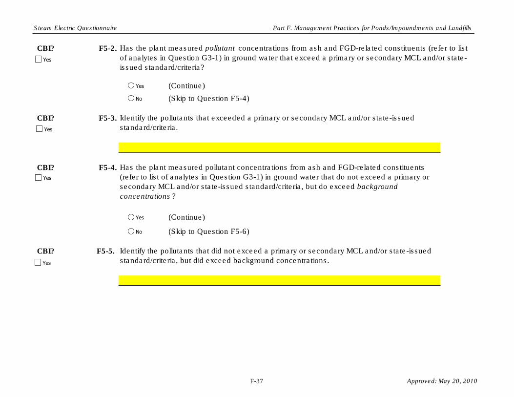
Steam Electric Questionnaire Part F. Management Practices for Ponds/Impoundments and Landfills
CBI? F5-2.
CBI? F5-3.
CBI? F5-4.
CBI? F5-5.
Identify the pollutants that exceeded a primary or secondary MCL and/or state-issued
standard/criteria.
(Continue)
(Skip to Question F5-6)
Has the plant measured pollutant concentrations from ash and FGD-related constituents
(refer to list of analytes in Question G3-1) in ground water that do not exceed a primary or
secondary MCL and/or state-issued standard/criteria, but do exceed background
concentrations ?
Identify the pollutants that did not exceed a primary or secondary MCL and/or state-issued
standard/criteria, but did exceed background concentrations.
Has the plant measured pollutant concentrations from ash and FGD-related constituents (refer to list
of analytes in Question G3-1) in ground water that exceed a primary or secondary MCL and/or state-
issued standard/criteria?
(Continue)
(Skip to Question F5-4)
Yes
No
Yes
No
Yes
Yes
Yes
Yes
F-37 Approved: May 20, 2010

Steam Electric Questionnaire Part F. Management Practices for Ponds/Impoundments and Landfills
CBI? F5-6.
Example: Well-1
Provide an overhead diagram of the pond/impoundment or landfill. Identify the location of the
monitoring wells of the pond/impoundment or landfill and assign each well a number. In Table F-14,
provide the average water table depth, averaged over the last year, at each monitoring well location
and the distance to the nearest surface water.
0.25 miles
Average Water Table Depth at
Well (ft)
Distance to Nearest Surface
Water (miles)
Table F-14. Monitoring Well Information
Monitoring Well ID
Number
26 feet
Yes
Diagram attached.
F-38 Approved: May 20, 2010

Steam Electric Questionnaire Part F. Management Practices for Ponds/Impoundments and Landfills
F-39 Approved: May 20, 2010

Steam Electric Questionnaire Part F. Management Practices for Ponds/Impoundments and Landfills
F-40 Approved: May 20, 2010

Steam Electric Questionnaire Part F. Management Practices for Ponds/Impoundments and Landfills
Plant Name: Insert Plant ID
Plant ID: Insert Plant Name
Part: F
Section Title: Part F Comments
Instructions:
Question Number
CBI?
CBI?
CBI?
CBI?
CBI?
CBI?
CBI?
CBI?
CBI?
CBI?
Cross reference your comments by question number and indicate the confidential status of your comment by checking the box
next to “Yes” under "CBI?" (Confidential Business Information).
Comment
Yes
Yes
Yes
Yes
Yes
Yes
Yes
Yes
Yes
Yes
F-41 Approved: May 20, 2010

Steam Electric Questionnaire Part F. Management Practices for Ponds/Impoundments and Landfills
CBI?
CBI?
CBI?
CBI?
CBI?
CBI?
CBI?
CBI?
Yes
Yes
Yes
Yes
Yes
Yes
Yes
Yes
F-42 Approved: May 20, 2010

Steam Electric Questionnaire Part F. Management Practices for Ponds/Impoundments and Landfills
Air heater cleaning water AHCWAsh pile runoff APR Effluent - 1 EFF-1Boiler blowdown BB Effluent - 2 EFF-2Boiler fireside cleaning water BFCW Effluent - 3 EFF-3Boiler tube cleaning water BTCW Effluent - 4 EFF-4Bottom ash sluice BAS Effluent - 5 EFF-5Carbon capture wastewater CCAPW Effluent - 6 EFF-6Coal pile runoff CPR Filter backwash FltBWCombined ash sluice CAS Sludge SLDGCombustion turbine cleaning (combustion gas portion of
turbine) water
COMBCW
Combustion turbine cleaning (compressor portion of the
turbine) water
COMPRCW POND-1 Effluent POND-1-EFF
Combustion turbine evaporative coolers blowdown TECB POND-2 Effluent POND-2-EFFCooling tower blowdown CTB POND-3 Effluent POND-3-EFFFGD scrubber purge SCRBP POND-4 Effluent POND-4-EFFFGD slurry blowdown FGDB POND-5 Effluent POND-5-EFFFilter Backwash FLTBW POND-6 Effluent POND-6-EFFFloor drain wastewater FDW POND-7 Effluent POND-7-EFFFlue gas mercury control system wastewater FGMCW POND-8 Effluent POND-8-EFFFly ash sluice FAS POND-9 Effluent POND-9-EFFGeneral runoff GR POND-10 Effluent POND-10-EFFGypsum pile runoff GPR POND-A Effluent POND-A-EFFGypsum wash water GYPWW POND-B Effluent POND-B-EFFIon exchange wastewater IXW POND-C Effluent POND-C-EFFLandfill runoff - capped landfill LRC WWT-1 Effluent WWT-1-EFFLandfill runoff - uncapped landfill LRUC WWT-2 Effluent WWT-2-EFFLeachate LEACH WWT-3 Effluent WWT-3-EFFLimestone pile runoff LPR WWT-4 Effluent WWT-4-EFFMill reject sluice MRS WWT-5 Effluent WWT-5-EFF
Steam Electric Questionnaire Code Tables
For Use as Effluents from Pond/Impoundment Systems
and/or Wastewater Treatment Systems in Part D, Table D-4.
Process Wastewaters Treated Wastewaters
For Use in Tables and Questions throughout Parts A, B, C, D, and F.
For Use as Influents to Pond/Impoundment Systems and/or
Wastewater Treatment Systems in Part D, Table D-3, AND
Recycled Waters Throughout Questionnaire.
Approved: May 20, 2010

Steam Electric Questionnaire Part F. Management Practices for Ponds/Impoundments and Landfills
Steam Electric Questionnaire Code Tables
Once -through cooling water CW WWT-6 Effluent WWT-6-EFFReverse osmosis reject water RORW WWT-A Effluent WWT-A-EFFSCR catalyst regeneration wastewater SCRRW WWT-B Effluent WWT-B-EFFSCR catalyst washing wastewater SCRWW WWT-C Effluent WWT-C-EFFSoot blowing wash water SOOTWSteam turbine cleaning water STCWYard drain wastewater YARDW
Process Wastewaters
For Use in Tables and Questions throughout Parts A, B, C, D, and F.
For Use as Influents to Pond/Impoundment Systems and/or
Wastewater Treatment Systems in Part D, Table D-3, AND
Recycled Waters Throughout Questionnaire.
Treated Wastewaters
Approved: May 20, 2010

Steam Electric Questionnaire Part F. Management Practices for Ponds/Impoundments and Landfills
Steam Electric Questionnaire Code Tables
Adsorptive media ADSORB Burned on site BURNAerobic Biological Reactor AERBIO Deep-well injection DWELL
Anaerobic Biological Reactor ANBIO Discharge to POTW POTWAerobic/Anaerobic Biological Reactor AER/ANBIO Discharge to PrOTW PrOTWChemical Precipitation Reaction Tank 1 - 1 CP-1-1 Discharge to surface water SWChemical Precipitation Reaction Tank 1 - 2 CP-1-2 Evaporation EVAPChemical Precipitation Reaction Tank 2 - 1 CP-2-1 Hauled off site for reuse
(removal fee)
HAULR - RF
Chemical Precipitation Reaction Tank 2 - 2 CP-2-2 Hauled off site for reuse (given
away)
HAULR - GA
Chemical Precipitation Reaction Tank 3 - 1 CP-3-1 Hauled off site for reuse
(marketed and sold)
SOLD
Chemical Precipitation Reaction Tank 3 - 2 CP-3-2 Hauled off site for disposal HAULClarification, Primary - 1 CL-P-1 Mixed with fly ash for disposal MFA
Clarification, Primary - 2 CL-P-2 On-site landfill (as reported in
Table A-6)
LANDF
Clarification, Secondary - 1 CL-S-1 POND-1 POND-1Clarification, Secondary - 2 CL-S-2 POND-2 POND-2Clarification, Tertiary - 1 CL-T-1 POND-3 POND-3Clarification, Tertiary - 2 CL-T-2 POND-4 POND-4Constructed wetland - Cell 1 CWL -1 POND-5 POND-5Constructed wetland - Cell 2 CWL -2 POND-6 POND-6Constructed wetland - Cell 3 CWL -3 POND-7 POND-7Constructed wetland - Cell 4 CWL -4 POND-8 POND-8Constructed wetland - Cell 5 CWL -5 POND-9 POND-9Constructed wetland - Cell 6 CWL -6 POND-10 POND-10Constructed wetland system CWTS POND-A POND-AEqualization, Primary EQ-P POND-B POND-BEqualization, Secondary EQ-S POND-C POND-CFilter, Microfiltration - 1 FLT-M-1 WWT-1 WWT-1Filter, Microfiltration - 2 FLT-M-2 WWT-2 WWT-2
Wastewater Treatment Units Destinations
For Use in Tables and Questions Throughout Parts A, C, D,
and F.For Use in Tables and Questions Throughout Parts D and F.
Approved: May 20, 2010

Steam Electric Questionnaire Part F. Management Practices for Ponds/Impoundments and Landfills
Steam Electric Questionnaire Code Tables
Filter, Microfiltration - 3 FLT-M-3 WWT-3 WWT-3
Filter, Microfiltration - 4 FLT-M-4 WWT-4 WWT-4Filter, Sand/Gravity - 1 FLT-S-1 WWT-5 WWT-5Filter, Sand/Gravity - 2 FLT-S-2 WWT-6 WWT-6Filter, Sand/Gravity - 3 FLT-S-3 WWT-A WWT-AFilter, Sand/Gravity - 4 FLT-S-4 WWT-B WWT-BFilter, Ultrafiltration - 1 FLT-U-1 WWT-C WWT-CFilter, Ultrafiltration - 2 FLT-U-2 Reuse as boiler water RECYC - BWFilter, Ultrafiltration - 3 FLT-U-3 Reuse as bottom ash sluice RECYC - BASFilter, Ultrafiltration - 4 FLT-U-4 Reuse as combined ash sluice RECYC - CAS
Filter press - 1 FP-1 Reuse as FGD slurry
preparation water
RECYC - FGDP
Filter press - 2 FP-2 Reuse as FGD absorber
makeup
RECYC - FGDAB
Holding tank HT Reuse as fly ash sluice RECYC - FASIon exchange IX Reuse as mill reject sluice RECYC - MRSNatural wetlands NW Reuse in cooling towers RECYC - CWpH adjustment - 1 PH-1pH adjustment - 2 PH-2pH adjustment - 3 PH-3Reverse osmosis ROSPond Unit - 1 SPD-1Pond Unit - 2 SPD-2Pond Unit - 3 SPD-3Pond Unit - 4 SPD-4Pond Unit - 5 SPD-5Pond Unit - 6 SPD-6Pond Unit - 7 SPD-7Pond Unit - 8 SPD-8Pond Unit - 9 SPD-9
Wastewater Treatment Units Destinations
For Use in Tables and Questions Throughout Parts D and F.For Use in Tables and Questions Throughout Parts A, C, D,
and F.
Approved: May 20, 2010

Steam Electric Questionnaire Part F. Management Practices for Ponds/Impoundments and Landfills
Steam Electric Questionnaire Code Tables
Pond Unit - 10 SPD-10Centrifuge - 1 CENT-1
Pond Unit - 11 SPD-11 Centrifuge - 2 CENT-2Pond Unit - 12 SPD-12 Centrifuge - 3 CENT-3Pond Unit - 13 SPD-13 Centrifuge - 4 CENT-4Pond Unit - 14 SPD-14 Hydrocyclones - 1 HYC-1Settling tank - 1 ST-1 Hydrocyclones - 2 HYC-2Settling tank - 2 ST-2 Hydrocyclones - 3 HYC-3Settling tank - 3 ST-3 Hydrocyclones - 4 HYC-4Settling tank - 4 ST-4 Filter press - 1 FP-1Settling tank - 5 ST-5 Filter press - 2 FP-2Thickener - 1 TH-1 Thickener - 1 TH-1Thickener - 2 TH-2 Thickener - 2 TH-2Vacuum drum filter - 1 VF-1 Vacuum drum filter - 1 VF-1Vacuum drum filter - 2 VF-2 Vacuum drum filter - 2 VF-2Vacuum filter belt - 1 VFB-1 Vacuum filter belt - 1 VFB-1Vacuum filter belt - 2 VFB-2 Vacuum filter belt - 2 VFB-2
Solids HandlingWastewater Treatment Units
For Use in Tables and Questions Throughout Parts D and F.For Use as Planned Solids Handling for the FGD Slurry
Blowdown in Part B Table B-2.
Approved: May 20, 2010

Steam Electric Questionnaire Part F. Management Practices for Ponds/Impoundments and Landfills
Part F Drop Downs
Process Wastewaters 1
Process Wastewaters 1
Select
Leachate
Stormwater
Other
Units
Units
Select
µg/L
mg/L
Process Wastewaters 2
Process Wastewaters 2
Select
Air heater cleaning water
Ash pile runoff
Boiler blowdown
Boiler fireside cleaning water
Boiler tube cleaning water
Bottom ash sluice
Carbon capture wastewater
Coal pile runoff
Combined ash sluice
Combustion turbine cleaning (combustion gas portion of turbine)
water
Combustion turbine cleaning (compressor portion of the turbine)
water
Combustion turbine evaporative coolers blowdown
Contaminated stormwater
Cooling tower blowdown
FGD scrubber purge
FGD slurry blowdown
Filter Backwash
Floor drain wastewater
Flue gas mercury control system wastewater
Fly ash sluice
General runoff
Gypsum pile runoff
Gypsum wash water
Ion exchange wastewater
Landfill runoff - capped landfill
Landfill runoff - uncapped landfill
Leachate
Limestone pile runoff
Mill reject sluice
Once -through cooling water
Reverse osmosis reject water
SCR catalyst regeneration wastewater
SCR catalyst washing wastewater
Soot blowing wash water
Steam turbine cleaning water
Yard drain wastewater
Other
Treated Wastewaters
Treated Wastewaters
Select
Effluent - 1
Effluent - 2
Effluent - 3
Effluent - 4
Effluent - 5
Effluent - 6
Filter backwash
Sludge
POND-1 Effluent
POND-2 Effluent
POND-3 Effluent
POND-4 Effluent
POND-5 Effluent
POND-6 Effluent
POND-7 Effluent
POND-8 Effluent
POND-9 Effluent
POND-10 Effluent
POND-A Effluent
POND-B Effluent
Approved: May 20, 2010

Steam Electric Questionnaire Part F. Management Practices for Ponds/Impoundments and Landfills
POND-C Effluent
WWT-1 Effluent
WWT-2 Effluent
WWT-3 Effluent
WWT-4 Effluent
WWT-5 Effluent
WWT-6 Effluent
WWT-A Effluent
WWT-B Effluent
WWT-C Effluent
Other
Leachate Treatment Units
Leachate Treatment Units
Select
Adsorptive media
Aerobic Biological Reactor
Anaerobic Biological Reactor
Aerobic/Anaerobic Biological Reactor
Chemical Precipitation Reaction Tank 1 - 1
Chemical Precipitation Reaction Tank 1 - 2
Chemical Precipitation Reaction Tank 2 - 1
Chemical Precipitation Reaction Tank 2 - 2
Chemical Precipitation Reaction Tank 3 - 1
Chemical Precipitation Reaction Tank 3 - 2
Clarification, Primary - 1
Clarification, Primary - 2
Clarification, Secondary - 1
Clarification, Secondary - 2
Clarification, Tertiary - 1
Clarification, Tertiary - 2
Constructed wetland - Cell 1
Constructed wetland - Cell 2
Constructed wetland - Cell 3
Constructed wetland - Cell 4
Constructed wetland - Cell 5
Constructed wetland - Cell 6
Constructed wetland system
Equalization, Primary
Equalization, Secondary
Filter, Microfiltration - 1
Filter, Microfiltration - 2
Filter, Microfiltration - 3
Filter, Microfiltration - 4
Filter, Sand/Gravity - 1
Filter, Sand/Gravity - 2
Filter, Sand/Gravity - 3
Filter, Sand/Gravity - 4
Filter, Ultrafiltration - 1
Filter, Ultrafiltration - 2
Filter, Ultrafiltration - 3
Filter, Ultrafiltration - 4
Filter press - 1
Filter press - 2
Holding tank
Ion exchange
Natural wetlands
pH adjustment - 1
pH adjustment - 2
pH adjustment - 3
Reverse osmosis
Pond Unit - 1
Pond Unit - 2
Pond Unit - 3
Pond Unit - 4
Pond Unit - 5
Pond Unit - 6
Pond Unit - 7
Pond Unit - 8
Pond Unit - 9
Pond Unit - 10
Pond Unit - 11
Pond Unit - 12
Pond Unit - 13
Pond Unit - 14
Settling tank - 1
Settling tank - 2
Settling tank - 3
Settling tank - 4
Settling tank - 5
Thickener - 1
Thickener - 2
Approved: May 20, 2010

OMB Control Number: 2040-0281 Plant ID: Insert Plant ID
Approval Expires: 05/31/2013 Plant Name: Insert Plant Name
Section Title Tab Name
Part G Instructions
Part G Section 1
Part G Section 2
Part G Section 3
Part G Section 4
Part G Section 5
Part G Sampling Results
Part G Comments
Landfills
Table of Contents
Leachate Collection
Part G Comments
Leachate Sample Collection Instructions
Sample Collection Information
Laboratory Analytical Data Form
Waste Information
Steam Electric Questionnaire
PART G - LEACHATE SAMPLING DATA FOR PONDS/IMPOUNDMENTS AND LANDFILLS
Part G Instructions
Leachate Generated from Ponds/Impoundments and
Approved: May 20, 2010

Steam Electric Questionnaire Part G. Instructions
Plant ID: Insert Plant ID
Plant Name: Insert Plant Name
PART G. LEACHATE SAMPLING DATA FOR PONDS/IMPOUNDMENTS AND
LANDFILLS
Use the Part G Comments tab to do the following: provide additional information as
requested in certain questions within Part G; indicate atypical data (e.g., if the analytical
data provided from the sample collection is not representative of normal operations);
and note methods used to make best engineering estimates in the event that exact data
are not available.
INSTRUCTIONS
Complete Part G of the questionnaire for your plant. As you are completing the
electronic form, note the following: When you enter your plant name and plant ID on the
Part G TOC tab, all name and ID fields throughout Part G will automatically populate.
Refer to the overall questionnaire instructions, the glossary, and the acronym list for
assistance with completing Part G.
Please provide all free response answers in the highlighted yellow areas. Throughout
Part G, you may need to make copies of certain sections/questions. Instructions are
provided throughout Part G regarding making copies. Note that pond/impoundment unit
and landfill names must be populated on the copied tab or section, located in the upper
right corner under "Plant ID" and "Plant Name", in order to correlate the requested
information with the pond/impoundment or landfill.
Sampling data and the completed Part G of the questionnaire shall be submitted
to EPA no later than 120 calendar days after receiving the questionnaire.
A company or plant may be exempt from the leachate sample collection (Question G3-
1). Please refer to Question G1-1 and the "Applicability" section located in the "Part G
Section 3" tab to determine if you are exempt and how to submit a written explanation.
Approved: May 20, 2010

Steam Electric Questionnaire Part G. Leachate Sampling Data for Ponds/Impoundments and Landfills
Part: G
Section Title:
Instructions:
CBI? G1-1.
(Skip to next Questionnaire Part)
1. Leachate Collection
Part G requests leachate sampling data for pond/impoundment units and landfills used for the storage, treatment, and/or
disposal of residues or by-products (or sludges or water streams containing the residues or by-products) from the
combustion of coal or petroleum coke, including, but not limited to, fly ash , bottom ash , boiler slag, or flue gas
desulfurization (FGD) system residues. This includes liquid-borne material and solid material.
Insert Plant ID
Insert Plant Name
Plant ID:
Plant Name:
(Skip to Section 2)
Note: This includes landfills located on non-adjoining property that are under the operational control of the plant. This also
includes landfills, within 20 miles, owned/operated by the plant's ultimate parent firm, for the purpose of storing/disposing of
process wastewaters, residues or by-products, from the plant.
Is leachate currently collected from any pond/impoundment and/or landfill , including those located on non-adjoining
property, that contains residues or by-products from the combustion of coal or petroleum coke? Please see the glossary for a
complete definition of leachate , which includes the terms seepage, leak, and leakage.
Yes
No
Yes
G-1 Approved: May 20, 2010

Steam Electric Questionnaire Part G. Leachate Sampling Data for Ponds/Impoundments and Landfills
Part: G
Section Title:
Instructions:
CBI? G2-1.
CBI? G2-2.
Insert Plant ID
Insert Plant Name
Insert ID
Plant ID:
Plant Name:
Pond/Impoundment Unit or Landfill ID:
2. Leachate Generated from Ponds/Impoundments and Landfills
(Continue)
Is all collected leachate transported off site for treatment and/or disposal?
Make copies of Section 2 (Questions G2-1 through G2-4) for each pond/impoundment unit and landfill , including those located on non-adjoining
property, used for the storage, treatment, and/or disposal of residues or by-products (or sludges or water streams containing the residues or by-
products) from the combustion of coal or petroleum coke, including, but not limited to, fly ash , bottom ash , boiler slag, or flue gas desulfurization
(FGD) system residues. This includes liquid-borne material and solid material. Enter the pond/impoundment unit or landfill ID in the space provided
above (use pond/impoundment unit and landfill IDs assigned in Table A-4 and Table A-6). Please provide all free response answers in the
highlighted yellow areas.
Note: This includes landfills located on non-adjoining property that are under the operational control of the plant. This also includes landfills, within
20 miles, owned/operated by the plant's ultimate parent firm, for the purpose of storing/disposing of process wastewaters, residues or by-products,
from the plant.
(Continue)
(Skip to Section 3. Provide ONLY untreated monitoring data as described in Question G3-1.)
(Skip to Section 5)
Is leachate currently collected from this pond/impoundment unit or landfill (excluding leachate returned to the pond/impoundment from which it
originated)?
Note: "Treatment" refers to the removal of specific pollutants or process wastewater constituents other than suspended solids. Refer to Figure G-1
below to help determine the leachate sample collection requirements for this pond/impoundment or landfill.
Make a copy of Section 2 for each pond/impoundment unit and landfill, including those located on non-adjoining property, using the "Copy Section 2"
button below.
Yes
No
Yes
No
Yes
Yes
Copy Section 2
G-2 Approved: May 20, 2010

Steam Electric Questionnaire Part G. Leachate Sampling Data for Ponds/Impoundments and Landfills
CBI? G2-3.
CBI? G2-4.
(Provide ONLY untreated monitoring data as described in Question G3-1)
(Continue)
(Skip to Section 3. Provide ONLY untreated monitoring data as described in Question G3-1.)
Is the leachate combined with other waste streams prior to treatment?
(Provide treated and untreated monitoring data as described in Question G3-1)
(Provide treated and untreated monitoring data as described in Question G3-1)
Is the collected leachate from this pond/impoundment unit or landfill that is not transferred off site currently treated?
Yes
Yes
No
Yes
Yes, combined with ONLY runoff or other stormwater
Yes, combined with process wastewater other than runoff/stormwater
No
G-3 Approved: May 20, 2010

Steam Electric Questionnaire Part G. Leachate Sampling Data for Ponds/Impoundments and Landfills
Figure G-1. Leachate Collection Decision Tree
G-4 Approved: May 20, 2010

Steam Electric Questionnaire Part G. Leachate Sampling Data for Ponds/Impoundments and Landfills
Part: G
Section Title:
G3-1.
Plant ID:
Plant Name:
Insert Plant ID
Insert Plant Name
3. Leachate Sample Collection Instructions
OVERVIEW OF THE SAMPLE COLLECTION
The samples should be collected as detailed in these instructions. In general, samples should be collected as grab samples (i.e.,
composite samples are not required). The plant should collect samples from each leachate collection point for each pond/impoundment
and landfill. If the plant determines that a sample from one or more collection points are representative of an individual
pond/impoundment or landfill, then the plant may simply collect the representative sample(s). The plant should collect samples from
each sampling location once per week for four consecutive weeks, or as soon thereafter as sufficient leachate is available for collection.
Sampling data and the completed Part G of the questionnaire shall be submitted to EPA no later than 120 calendar days after
receiving the questionnaire.
Collect process wastewater samples of untreated and/or treated leachate streams generated from pond(s)/impoundment(s) and
landfill(s) used for the storage, treatment, or disposal of residues or by-products (or sludges or water streams containing the residues
or by-products) from the combustion of coal or petroleum coke, including, but not limited to, fly ash , bottom ash , boiler slag, or flue gas
desulfurization (FGD) system residues (this includes liquid-borne material and solid material).
G-5 Approved: May 20, 2010

Steam Electric Questionnaire Part G. Leachate Sampling Data for Ponds/Impoundments and Landfills
• Metals (total recoverable; antimony,
arsenic, beryllium, cadmium,
chromium, cobalt, copper, lead,
manganese, molybdenum, nickel,
selenium, silver, thallium, vanadium,
and zinc)
EPA Method 200.8
• Metals (total recoverable: aluminum,
barium, boron, calcium, iron,
magnesium, sodium, tin, and titanium)
EPA Method 200.7 or 200.8
• Mercury EPA Method 1631E
• Chlorides 40 CFR Part 136-approved
• Sulfates 40 CFR Part 136-approved
• Total dissolved solids (TDS) 40 CFR Part 136-approved
• Total suspended solids (TSS) 40 CFR Part 136-approved
• pH 40 CFR Part 136-approved
• Must have data from leachate generated from each pond/impoundment and landfill where leachate is collected;
• Must have at least four samples of untreated and/or treated leachate, where each sample is collected at least five
days apart; and
• Must have tested for every analyte listed above using the specified analytical methods.
The following analytes and analytical methods must be used for the sample analysis:
2. The plant personnel are unable to collect the samples safely.
Each company or plant is responsible for identifying and contracting an analytical laboratory to perform the analyses.
A plant may be exempt from the leachate sample collection (and skip to Question G3-2) if one of these two circumstances is true:
1. The plant can provide previously collected leachate characterization data if it fulfills the following data requirements:
APPLICABILITY
G-6 Approved: May 20, 2010

Steam Electric Questionnaire Part G. Leachate Sampling Data for Ponds/Impoundments and Landfills
Jezebele Alicea
US EPA
Engineering and Analysis Division
Mail Code: 4303T
1200 Pennsylvania Avenue, N.W.
Washington, DC 20460
SAMPLE LOCATION
Collect untreated and/or treated leachate samples from each pond/impoundment unit and landfill for which you responded "yes" in
Question G2-1.
If the pond/impoundment unit and/or landfill has multiple collection points, the untreated sample may be collected from a common
header area, if applicable. If there is not a common header area for the pond/impoundment or landfill, the plant may select one of the
collection points that is "representative" of the pond/impoundment or landfill from which to collect the sample. If warranted due to the
characteristics of the pond/impoundment or landfill, the plant may need to collect samples from more than one collection point to obtain
representative samples. If the plant collects the samples from one ”representative” collection point, describe how the company or plant
determined the collection point is “representative” of all of the collection points in the “Part G Comments” tab located at the end of Part
G.
If you believe you are exempt, you must submit a written explanation justifying one or both of these two circumstances within
two weeks after receiving the questionnaire by e-mail (preferred) or mailed to:
EPA will then determine if the plant is exempt from the leachate sample collection requirement. If the plant can provide previously
collected leachate characterization data, then the plant should complete Section 4 (Questions G4-1 and G4-2) and continue to Section
5 (Question G5-1). Also, the plant must provide the leachate sampling data in Table G-4 found in the "Part G Sampling Results" tab. If
the plant cannot collect the samples safely, then the plant should skip Section 4 and continue to Section 5 (Question G5-1).
The untreated leachate samples must be collected directly from the leachate collection system or holding tank prior to any form of
treatment. The treated leachate samples must be collected from the effluent from a leachate treatment system that is designed for the
purpose of removing pollutants or process wastewater constituents, other than suspended solids, prior to discharge or commingling
with other process wastewaters.
G-7 Approved: May 20, 2010

Steam Electric Questionnaire Part G. Leachate Sampling Data for Ponds/Impoundments and Landfills
CBI? G3-2.
CBI? G3-3.
SAMPLE FREQUENCY
Collect one sample of untreated leachate (and one sample of treated leachate if appropriately identified by responses in Question G2-
4) once per week for four weeks, or as soon thereafter as sufficient leachate is available for collection, from each pond/impoundment
unit and landfill. Please note that the samples must be collected at least five days after the previous sample was collected. If the
pond/impoundment or landfill does not generate leachate weekly, please collect the samples as soon as the leachate is generated, but
allow at least five days between samples.
Please attach an aerial photograph or drawing showing the entire waste management unit (i.e., pond/impoundment unit or landfill) that
shows the boundaries and identifies all leachate collection points and the active and inactive areas of the pond/impoundment or landfill.
Also, indicate the leachate sample location(s) used for this sample collection in the aerial photograph or drawing of the
pond/impoundment unit or landfill.
Please identify the leachate sample locations used for this sample collection in the block diagram previously requested in Question F4-
2.
QUALITY ASSURANCE/QUALITY CONTROL
Example 2: If a plant collects both untreated and treated leachate from both a pond/impoundment unit and a landfill, and each
separately has a single leachate collection point and they have separate treatment systems, the plant is required to collect a
total of sixteen samples.
Follow the method-specified quality assurance/quality control analyses and attach a data review summary once the analyses are
complete.
SAMPLE ANALYSES
After receiving the analytical results from the laboratory, enter the analytical data into the “Part G Sampling Results” tab. Report all
results, including those below the reporting limit. Identify results that are less than the method detection limit (MDL), and results that
are between the detection and reporting limits . For example, if the MDL is equal to 5 ng/L, the reporting limit is equal to 15 ng/L, and
the value reported by the laboratory is 12 ng/L, report 12 ng/L as the measured value and identify and describe any qualifiers on the
data in the corresponding column. If the measured value is not detected, list the detection limit value and select the less than (<) symbol
in the non-detect indicator column.
Example1: If a plant collects only untreated leachate from a pond/impoundment unit, and the samples are obtained from a
single leachate collection point, the plant is required to collect a total of four samples.
Yes
Yes
I have attached the aerial photograph
I did not attach the aerial photograph. Explain why:
Leachate sampling collection locations identified on the block diagram requested in Part F, Question F4-2.
G-8 Approved: May 20, 2010

Steam Electric Questionnaire Part G. Leachate Sampling Data for Ponds/Impoundments and Landfills
Plant ID: Insert Plant ID
Plant Name: Insert Plant Name
Part: G
Section Title:
Instructions:
G4-1.
Pond/Impoundment
Unit or Landfill ID
(Use IDs from Tables
A-4 and A-6)
Sample Collection
Location Description
Date of Sample
Collection
(mm/dd/yyyy)
Leachate Treatment System ID:
CBI? Leachate Treatment System ID:
CBI? Leachate Treatment System ID:
CBI? Leachate Treatment System ID:
CBI? Leachate Treatment System ID:
Common header area
Table G-1. Sample Collection Information
In Table G-1, provide a description of the sample collection location, the date the sample was collected, the flow rate of the leachate
stream from the collection point (select the units of the flow rate), and identify if the leachate stream is treated or untreated. If the
leachate sample is treated, provide the leachate treatment system ID previously identified in Table F-5.
Sample Collection Location
01/25/10Example
Complete Table G-1 for each pond/impoundment unit and landfill that requires leachate sampling and is used for the storage, treatment,
and/or disposal of residues or by-products (or sludges or water streams containing the residues or by-products) from the combustion of
coal or petroleum coke, including, but not limited to, fly ash , bottom ash , boiler slag, or flue gas desulfurization (FGD) system residues.
This includes liquid-borne material and solid material. Enter the pond/impoundment unit or landfill ID in the first column of Table G-1
(use pond/impoundment unit and landfill IDs assigned in Table A-4 and Table A-6). Please provide all free response answers in the
highlighted yellow areas.
Collect daily rainfall data starting two weeks prior to collection of the first sample through the day of the last sample collected and enter
the date and inches of rainfall in Table G-2.
4. Sample Collection Information
Yes
Yes
Yes
Yes
Untreated pond/impoundment
Sample Collection Location
Sample Collection Location
Sample Collection Location
Sample Collection Location
G-9 Approved: May 20, 2010

Steam Electric Questionnaire Part G. Leachate Sampling Data for Ponds/Impoundments and Landfills
CBI? G4-2.
Date
(mm/dd/yyyy) Inches of Rainfall
Date
(mm/dd/yyyy) Inches of Rainfall
Table G-2. Rainfall Data
In Table G-2, provide the inches of rainfall accumulated at the plant on a daily basis starting two weeks prior to the collection of the first
leachate sample through the last day of sample collection.Yes
G-10 Approved: May 20, 2010

Steam Electric Questionnaire Part G. Leachate Sampling Data for Ponds/Impoundments and Landfills
Plant ID:
Plant Name:
Part: G
Section Title:
Instructions:
G5-1.
Pond/Impoundment
Unit or Landfill ID
(Use IDs from Tables
A-4 and A-6)
CBI? tons tons tons
tons tons tons
tons tons tons
CBI? tons tons tons
tons tons tons
tons tons tons
CBI? tons tons tons
tons tons tons
tons tons tons
CBI? tons tons tons
tons tons tons
tons tons tons
CBI? tons tons tons
tons tons tons
tons tons tons
Insert Plant ID
Insert Plant Name
5. Waste Information
Complete Table G-3 for each pond/impoundment unit and landfill , including those located on non-adjoining property, that is used for the storage, treatment, and/or disposal of residues
or by-products (or sludges or water streams containing the residues or by-products) from the combustion of coal or petroleum coke, including, but not limited to, fly ash , bottom ash ,
boiler slag, or flue gas desulfurization (FGD) system residues. This includes liquid-borne material and solid material. Enter the pond/impoundment unit or landfill ID in the first column of
Table G-3 (use pond/impoundment unit and landfill IDs assigned in Table A-4 and Table A-6). Please provide all free response answers in the highlighted yellow areas.
Make a copy of Section 5 to complete as many tables as needed to provide information for all pond/impoundment units and landfills, including those located on non-adjoining property,
using the "Copy Section 5" button below.
In Table G-3, indicate all process wastes, residues or by-products that are stored, treated, and/or disposed of in each pond/impoundment unit and/or landfill [Check all that apply].
Please provide any additional wastes not listed by selecting “Other” and specifying the process waste, residue, or by-product in the highlighted yellow space provided. Complete as
many rows of the table as needed to represent all pond/impoundment units and landfills at the plant. If more rows are needed, make additional copies of Table G-3 and complete as
many tables as needed to provide information for all pond/impoundment units and landfills identified in Table A-4 and A-6.
Type and Amount of Waste
Table G-3. Waste Information
Fly ash
Bottom ash
Boiler slag
FGD Calcium Sulfate (Gypsum)
FGD Calcium Sulfate - Not Pozzolanic
FGD Pozzolanic Material
Other:
Other:
Other:
FGD Calcium Sulfate (Gypsum)
FGD Calcium Sulfate - Not Pozzolanic
FGD Pozzolanic Material
FGD Calcium Sulfate (Gypsum)
FGD Calcium Sulfate - Not Pozzolanic
FGD Pozzolanic Material
FGD Calcium Sulfate (Gypsum)
FGD Calcium Sulfate - Not Pozzolanic
FGD Pozzolanic Material
FGD Calcium Sulfate (Gypsum)
FGD Calcium Sulfate - Not Pozzolanic
FGD Pozzolanic Material
Other:
Other:
Other:
Other:
Other:
Other:
Other:
Other:
Other:
Other:
Other:
Other:
Fly ash
Bottom ash
Boiler slag
Fly ash
Bottom ash
Boiler slag
Fly ash
Bottom ash
Boiler slag
Fly ash
Bottom ash
Boiler slag
Yes
Yes
Yes
Yes
Yes
Copy Section 5
G-11 Approved: May 20, 2010

Steam Electric Questionnaire Part G. Leachate Sampling Data for Ponds/Impoundments and Landfills
Plant ID: Insert Plant ID
Plant Name: Insert Plant Name
Pond/Impoundment Unit or Landfill ID: Insert ID
Sample Collection Location:
Part: G
Section Title:
Instructions:
CBI?
CBI?
CBI?
Name of Analyte CAS Number
Non-
Detect
Indicator
Concentration*
(µg/L)
Method
Detection Limit
(MDL) (µg/L)
Reporting Limit
(µg/L) Qualifiers for the Measurement
Other:
Other:
Other:
Other:
Other:
Other:
Other:
Other:
7440-42-8Boron
7440-43-9Cadmium
Beryllium 7440-41-7
Analytical Method Used
7440-36-0
Arsenic
Barium 7440-39-3
Laboratory Analytical Data Form
Aluminum 7429-90-5
Example - Arsenic 7440-38-2 350 2
Complete Table G-4 for each untreated and treated sample collection locations. Enter the pond/impoundment unit or landfill ID (use pond/impoundment unit and landfill IDs assigned in Table
A-4 and Table A-6) and the sample collection location (identified previously in Table G-1) in the spaces provided above. Also, identify the name of the analytical laboratory that conducted the
analyses and provide the sample collection location description previously identified in Table G-1. Report all results, including those below the reporting limit. Identify results that are less than
the method detection limit (MDL), and results that are between the detection and reporting limits. For example, if the MDL is equal to 5 ng/L, the reporting limit is equal to 15 ng/L, and the
value reported by the laboratory is 12 ng/L, report 12 ng/L as the measured value and identify and describe any qualifiers on the data in the corresponding column. If the measured value is not
detected, list the detection limit value and select the less than (<) symbol in the non-detect indicator column. Please provide all free response answers in the highlighted yellow areas.
Make a copy of Sampling Results Table for the each pond/impoundment unit and landfill chosen for the leachate sample collection using the "Copy Sampling Results Table" button below.
7440-38-2
Table G-4. Leachate Sampling Analytical Data Form
Name of analytical laboratory:
Sample collection location description:
Antimony
10
Detected in laboratory blank at less
than 5 times the sample result
Yes
Copy Sampling Results Table
Data review summary attached.
Sample Collection Location
EPA Method 200.7
Analytical Method
Analytical Method
Analytical Method
Analytical Method
Analytical Method
Analytical Method
Analytical Method
Non-Detect Drop Down
Non-Detect Drop Down
Non-Detect Drop Down
Non-Detect Drop Down
Non-Detect Drop Down
Non-Detect Drop Down
Non-Detect Drop Down
Non-Detect Drop Down
Yes
Yes
G-12 Approved: May 20, 2010

Steam Electric Questionnaire Part G. Leachate Sampling Data for Ponds/Impoundments and Landfills
Other:
Other:
Other:
Other:
Other:
Other:
Other:
Other:
Other:
Other:
Other:
Other:
Other:
Other:
Other:
Other:
Other:
Other:
Other:
Other:
Other:
Other:
Other:
Other:
7439-97-6
No CAS
7440-31-5
7440-32-6
7440-62-2
7440-66-6
7440-22-4
7440-23-5
No CAS
7440-28-0
7439-95-4
7439-98-7
7440-02-0
7782-49-2
No CAS
No CAS
No CAS
7440-70-2
7440-47-3
7440-48-4
7440-50-8
7439-89-6
7439-92-1
7439-95-4
Chlorides
Total dissolved solids (TDS)
Total suspended solids (TSS)
pH
Titanium
Vanadium
Zinc
Mercury
Sodium
Sulfate
Thallium
Tin
Molybdenum
Nickel
Selenium
Silver
Iron
Lead
Magnesium
Manganese
Calcium
Chromium
Cobalt
Copper
*If not detected, list the detection limit value and select the less than (<) symbol in the non-detect indicator column.
Analytical Method
Analytical Method
Analytical Method
Analytical Method
Analytical Method
Analytical Method
Analytical Method
Analytical Method
Analytical Method
Analytical Method
Analytical Method
Analytical Method
Analytical Method
Analytical Method
Analytical Method
Analytical Method
Analytical Method
Analytical Method
Analytical Method
Analytical Method
Analytical Method
Analytical Method
Analytical Method
Analytical Method
Non-Detect Drop Down
Non-Detect Drop Down
Non-Detect Drop Down
Non-Detect Drop Down
Non-Detect Drop Down
Non-Detect Drop Down
Non-Detect Drop Down
Non-Detect Drop Down
Non-Detect Drop Down
Non-Detect Drop Down
Non-Detect Drop Down
Non-Detect Drop Down
Non-Detect Drop Down
Non-Detect Drop Down
Non-Detect Drop Down
Non-Detect Drop Down
Non-Detect Drop Down
Non-Detect Drop Down
Non-Detect Drop Down
Non-Detect Drop Down
Non-Detect Drop Down
Non-Detect Drop Down
Non-Detect Drop Down
Non-Detect Drop Down
G-13 Approved: May 20, 2010
Steam Electric Questionnaire Part G. Leachate Sampling Data for Ponds/Impoundments and Landfills
Plant Name: Insert Plant ID
Plant ID: Insert Plant Name
Part: G
Section Title: Part G Comments
Instructions:
Question Number
CBI?
CBI?
CBI?
CBI?
CBI?
CBI?
CBI?
CBI?
CBI?
CBI?
CBI?
CBI?
CBI?
Cross reference your comments by question number and indicate the confidential status of your comment by checking the box next to "Yes" under
"CBI?" (Confidential Business Information).
Comment
Yes
Yes
Yes
Yes
Yes
Yes
Yes
Yes
Yes
Yes
Yes
Yes
Yes
G-14 Approved: May 20, 2010

Steam Electric Questionnaire Part G. Leachate Sampling Data for Ponds/Impoundments and Landfills
CBI?
CBI?
CBI?
CBI?
CBI?
CBI?
CBI?
CBI?
CBI?
CBI?
CBI?
CBI?
Yes
Yes
Yes
Yes
Yes
Yes
Yes
Yes
Yes
Yes
Yes
Yes
G-15 Approved: May 20, 2010

Steam Electric Questionnaire Part G. Leachate Sampling Data for Ponds/Impoundments and Landfills
Analytical Method Sample Collection Location
Analytical Method Sample Collection Location
40 CRF Part 136-approved Treated pond/impoundment
EPA Method 200.7 Untreated pond/impoundment
EPA Method 200.8 Treated Landfill
EPA Method 1631E Untreated Landfill
Other
Non-Detect Drop Down
Non-Detect Drop Down
<
Part G Drop Downs
Approved: May 20, 2010

OMB Control Number: 2040-0281 Plant ID: Insert Plant ID
Approval Expires: 05/31/2013 Plant Name: Insert Plant Name
Section Title Tab Name
Part H Instructions Part H Instructions
Nuclear Generating Unit Data Part H Section 1
Process Wastewater Generation Part H Section 2
Wastewater Treatment Systems Part H Section 3
Part H Comments Part H Comments
PART H - NUCLEAR POWER GENERATION
Steam Electric Questionnaire
Table of Contents
Approved: May 20, 2010

Steam Electric Questionnaire Part H. Instructions
Plant ID: Insert Plant ID
Plant Name: Insert Plant Name
PART H.
Note: The following acronyms are used throughout Part H:
PWR - Pressurized water reactor
BWR - Boiling water reactor
Use the Part H Comments tab to do the following: provide additional information as
requested in certain questions within Part H; indicate atypical data (e.g., if 2009
information is not representative of normal operations); and note methods used to make
best engineering estimates in the event that exact data are not available.
NUCLEAR POWER GENERATION
INSTRUCTIONS
Complete Part H of the questionnaire for your plant. As you are completing the
electronic form, note the following: When you enter your plant name and plant ID on the
Part H TOC tab, all name and ID fields throughout Part H will automatically populate.
Refer to the overall questionnaire instructions, the glossary, and the acronym list for
assistance with completing Part H.
Please provide all free response answers in the highlighted yellow areas. Throughout
Part H, you may need to make copies of certain sections/questions. Instructions are
provided throughout Part H regarding making copies. Note that process wastewater
codes or wastewater treatment system names must be populated on the copied tab or
section, located in the upper right corner under "Plant ID" and "Plant Name", in order to
correlate the requested information with the process wastewater or wastewater
treatment system.
Approved: May 20, 2010

Steam Electric Questionnaire Part H. Nuclear Power Generation
Plant ID: Insert Plant ID
Plant Name: Insert Plant Name
Part: H
Section Title: 1. Nuclear Generating Unit Data
Instructions:
CBI? H1-1.
CBI? H1-2.
CBI? H1-3.
(Skip to next Questionnaire Part)
(Skip to next Questionnaire Part)
Complete Section 1 (Questions H1-1 through H1-3) for each nuclear electric generating unit that the plant operated during 2009. Provide all
free response answers in the highlighted yellow areas.
Did the plant generate any process wastewater (with the exception of wastewater from service water treatment systems) during 2009 that is
associated with the production of electricity from nuclear generating units? Examples include, but are not limited to, containment sump
water and water generated from cooling system leaks or loss of coolant accidents (LOCA).
In Table H-1, provide information for all process wastewater associated with the production of electricity from the nuclear electric generating
units that the plant operated during 2009. Indicate the nuclear generating unit(s) that are associated with each process wastewater. [Check
all boxes that apply.] If the process wastewater is associated with the entire plant, all nuclear units should be checked. If the plant generated
a process wastewater that is not in the drop down menu, include the name and description of the process wastewater in the space provided
and indicate the nuclear generating unit(s) that are associated with the process wastewater.
Did the plant operate one or more units using nuclear energy as the fuel source to generate electricity in 2009?
(Continue)
(Continue)
Yes
Yes
No
Yes
No
Yes
Yes
H-1 Approved: May 20, 2010

Steam Electric Questionnaire Part H. Nuclear Power Generation
Process Wastewater
Code
Other, specify:
Other, specify:
Other, specify:
Other, specify:
Other, specify:
Other, specify:
Other, specify:
NUC-1
Table H-1. Process Wastewater Associated with Nuclear Electric Generating Units
Process Wastewater
Nuclear Unit(s) Associated with
Process Wastewater
NUC-2
NUC-3
NUC-4
NUC-5
NUC-6
NUC-7
SE Unit 1
SE Unit 2
SE Unit 3
SE Unit 4
SE Unit 5
SE Unit 6
SE Unit 7
SE Unit 8
SE Unit 9
Other, specify:
Process Wastewater Nonradioactive/Radioactive
Process Wastewater Nonradioactive/Radioactive
Process Wastewater Nonradioactive/Radioactive
Process Wastewater Nonradioactive/Radioactive
Process Wastewater Nonradioactive/Radioactive
Process Wastewater Nonradioactive/Radioactive
Process Wastewater Nonradioactive/Radioactive
SE Unit 1
SE Unit 2
SE Unit 3
SE Unit 4
SE Unit 5
SE Unit 6
SE Unit 7
SE Unit 8
SE Unit 9
Other, specify:
SE Unit 1
SE Unit 2
SE Unit 3
SE Unit 4
SE Unit 5
SE Unit 6
SE Unit 7
SE Unit 8
SE Unit 9
Other, specify:
SE Unit 1
SE Unit 2
SE Unit 3
SE Unit 4
SE Unit 5
SE Unit 6
SE Unit 7
SE Unit 8
SE Unit 9
Other, specify:
SE Unit 1
SE Unit 2
SE Unit 3
SE Unit 4
SE Unit 5
SE Unit 6
SE Unit 7
SE Unit 8
SE Unit 9
Other, specify:
SE Unit 1
SE Unit 2
SE Unit 3
SE Unit 4
SE Unit 5
SE Unit 6
SE Unit 7
SE Unit 8
SE Unit 9
Other, specify:
SE Unit 1
SE Unit 2
SE Unit 3
SE Unit 4
SE Unit 5
SE Unit 6
SE Unit 7
SE Unit 8
SE Unit 9
Other, specify:
H-2 Approved: May 20, 2010

Steam Electric Questionnaire Part H. Nuclear Power Generation
Other, specify:
Other, specify:
Other, specify:
Other, specify:
Other, specify:
Other, specify:
Other, specify:
Other, specify:
Other, specify:
NUC-8
NUC-9
NUC-10
NUC-11
NUC-12
NUC-13
NUC-14
NUC-15
NUC-16
Process Wastewater Nonradioactive/Radioactive
Process Wastewater Nonradioactive/Radioactive
Process Wastewater Nonradioactive/Radioactive
Process Wastewater Nonradioactive/Radioactive
Process Wastewater Nonradioactive/Radioactive
Process Wastewater Nonradioactive/Radioactive
Process Wastewater Nonradioactive/Radioactive
Process Wastewater Nonradioactive/Radioactive
Process Wastewater Nonradioactive/Radioactive
SE Unit 1
SE Unit 2
SE Unit 3
SE Unit 4
SE Unit 5
SE Unit 6
SE Unit 7
SE Unit 8
SE Unit 9
Other, specify:
SE Unit 1
SE Unit 2
SE Unit 3
SE Unit 4
SE Unit 5
SE Unit 6
SE Unit 7
SE Unit 8
SE Unit 9
Other, specify:
SE Unit 1
SE Unit 2
SE Unit 3
SE Unit 4
SE Unit 5
SE Unit 6
SE Unit 7
SE Unit 8
SE Unit 9
Other, specify:
SE Unit 1
SE Unit 2
SE Unit 3
SE Unit 4
SE Unit 5
SE Unit 6
SE Unit 7
SE Unit 8
SE Unit 9
Other, specify:
SE Unit 1
SE Unit 2
SE Unit 3
SE Unit 4
SE Unit 5
SE Unit 6
SE Unit 7
SE Unit 8
SE Unit 9
Other, specify:
SE Unit 1
SE Unit 2
SE Unit 3
SE Unit 4
SE Unit 5
SE Unit 6
SE Unit 7
SE Unit 8
SE Unit 9
Other, specify:
SE Unit 1
SE Unit 2
SE Unit 3
SE Unit 4
SE Unit 5
SE Unit 6
SE Unit 7
SE Unit 8
SE Unit 9
Other, specify:
SE Unit 1
SE Unit 2
SE Unit 3
SE Unit 4
SE Unit 5
SE Unit 6
SE Unit 7
SE Unit 8
SE Unit 9
Other, specify:
SE Unit 1
SE Unit 2
SE Unit 3
SE Unit 4
SE Unit 5
SE Unit 6
SE Unit 7
SE Unit 8
SE Unit 9
Other, specify:
H-3 Approved: May 20, 2010

Steam Electric Questionnaire Part H. Nuclear Power Generation
Other, specify:
Other, specify:
Other, specify:
Other, specify:
Other, specify:
Other, specify:
Other, specify:
Other, specify:
Other, specify:
NUC-18
NUC-19
NUC-20
NUC-17
NUC-21
NUC-22
NUC-23
NUC-24
NUC-25
Process Wastewater Nonradioactive/Radioactive
Process Wastewater Nonradioactive/Radioactive
Process Wastewater Nonradioactive/Radioactive
Process Wastewater Nonradioactive/Radioactive
Process Wastewater Nonradioactive/Radioactive
Process Wastewater Nonradioactive/Radioactive
Process Wastewater Nonradioactive/Radioactive
Process Wastewater Nonradioactive/Radioactive
Process Wastewater Nonradioactive/Radioactive
SE Unit 1
SE Unit 2
SE Unit 3
SE Unit 4
SE Unit 5
SE Unit 6
SE Unit 7
SE Unit 8
SE Unit 9
Other, specify:
SE Unit 1
SE Unit 2
SE Unit 3
SE Unit 4
SE Unit 5
SE Unit 6
SE Unit 7
SE Unit 8
SE Unit 9
Other, specify:
SE Unit 1
SE Unit 2
SE Unit 3
SE Unit 4
SE Unit 5
SE Unit 6
SE Unit 7
SE Unit 8
SE Unit 9
Other, specify:
SE Unit 1
SE Unit 2
SE Unit 3
SE Unit 4
SE Unit 5
SE Unit 6
SE Unit 7
SE Unit 8
SE Unit 9
Other, specify:
SE Unit 1
SE Unit 2
SE Unit 3
SE Unit 4
SE Unit 5
SE Unit 6
SE Unit 7
SE Unit 8
SE Unit 9
Other, specify:
SE Unit 1
SE Unit 2
SE Unit 3
SE Unit 4
SE Unit 5
SE Unit 6
SE Unit 7
SE Unit 8
SE Unit 9
Other, specify:
SE Unit 1
SE Unit 2
SE Unit 3
SE Unit 4
SE Unit 5
SE Unit 6
SE Unit 7
SE Unit 8
SE Unit 9
Other, specify:
SE Unit 1
SE Unit 2
SE Unit 3
SE Unit 4
SE Unit 5
SE Unit 6
SE Unit 7
SE Unit 8
SE Unit 9
Other, specify:
SE Unit 1
SE Unit 2
SE Unit 3
SE Unit 4
SE Unit 5
SE Unit 6
SE Unit 7
SE Unit 8
SE Unit 9
Other, specify:
H-4 Approved: May 20, 2010

Steam Electric Questionnaire Part H. Nuclear Power Generation
Other, specify:
Other, specify:
Other, specify:
Other, specify:
Other, specify:
Other, specify:
Other, specify:
Other, specify:
Other, specify:
NUC-26
NUC-27
NUC-28
NUC-29
NUC-30
NUC-31
NUC-32
NUC-33
NUC-34
Process Wastewater Nonradioactive/Radioactive
Process Wastewater Nonradioactive/Radioactive
Process Wastewater Nonradioactive/Radioactive
Process Wastewater Nonradioactive/Radioactive
Process Wastewater Nonradioactive/Radioactive
Process Wastewater Nonradioactive/Radioactive
Process Wastewater Nonradioactive/Radioactive
Process Wastewater Nonradioactive/Radioactive
Process Wastewater Nonradioactive/Radioactive
SE Unit 1
SE Unit 2
SE Unit 3
SE Unit 4
SE Unit 5
SE Unit 6
SE Unit 7
SE Unit 8
SE Unit 9
Other, specify:
SE Unit 1
SE Unit 2
SE Unit 3
SE Unit 4
SE Unit 5
SE Unit 6
SE Unit 7
SE Unit 8
SE Unit 9
Other, specify:
SE Unit 1
SE Unit 2
SE Unit 3
SE Unit 4
SE Unit 5
SE Unit 6
SE Unit 7
SE Unit 8
SE Unit 9
Other, specify:
SE Unit 1
SE Unit 2
SE Unit 3
SE Unit 4
SE Unit 5
SE Unit 6
SE Unit 7
SE Unit 8
SE Unit 9
Other, specify:
SE Unit 1
SE Unit 2
SE Unit 3
SE Unit 4
SE Unit 5
SE Unit 6
SE Unit 7
SE Unit 8
SE Unit 9
Other, specify:
SE Unit 1
SE Unit 2
SE Unit 3
SE Unit 4
SE Unit 5
SE Unit 6
SE Unit 7
SE Unit 8
SE Unit 9
Other, specify:
SE Unit 1
SE Unit 2
SE Unit 3
SE Unit 4
SE Unit 5
SE Unit 6
SE Unit 7
SE Unit 8
SE Unit 9
Other, specify:
SE Unit 1
SE Unit 2
SE Unit 3
SE Unit 4
SE Unit 5
SE Unit 6
SE Unit 7
SE Unit 8
SE Unit 9
Other, specify:
SE Unit 1
SE Unit 2
SE Unit 3
SE Unit 4
SE Unit 5
SE Unit 6
SE Unit 7
SE Unit 8
SE Unit 9
Other, specify:
H-5 Approved: May 20, 2010
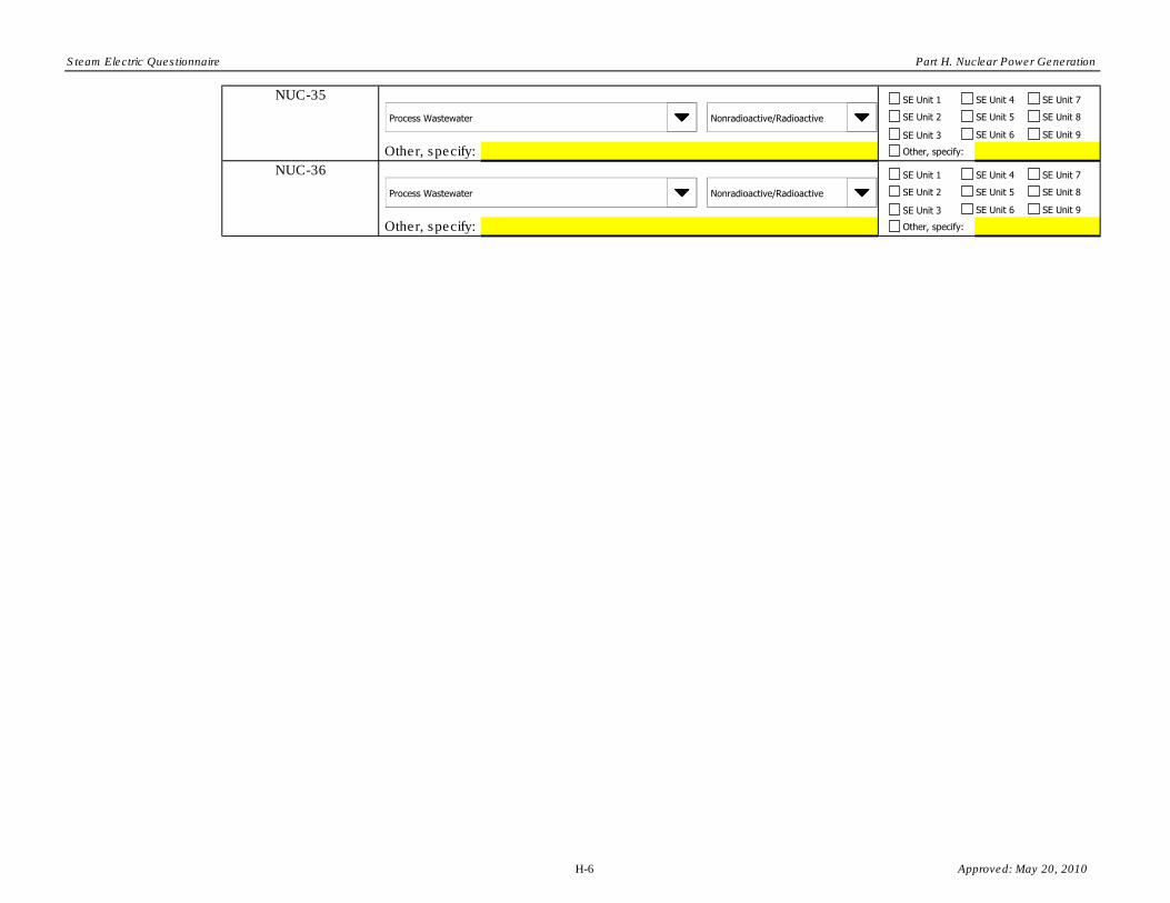
Steam Electric Questionnaire Part H. Nuclear Power Generation
Other, specify:
Other, specify:
NUC-36
NUC-35
Process Wastewater Nonradioactive/Radioactive
Process Wastewater Nonradioactive/Radioactive
SE Unit 1
SE Unit 2
SE Unit 3
SE Unit 4
SE Unit 5
SE Unit 6
SE Unit 7
SE Unit 8
SE Unit 9
Other, specify:
SE Unit 1
SE Unit 2
SE Unit 3
SE Unit 4
SE Unit 5
SE Unit 6
SE Unit 7
SE Unit 8
SE Unit 9
Other, specify:
H-6 Approved: May 20, 2010

Steam Electric Questionnaire Part H. Nuclear Power Generation
Plant ID:
Plant Name:
Process wastewater code:
Part: H
Section Title: 2. Process Wastewater Generation
Instructions:
CBI? H2-1.
Process Wastewater
Flow
hpd dpy
hpd dpy time(s) every year(s)
Indicate in Table H-2 if the process wastewater flow is continuous or not continuous. For process wastewater with
a continuous flow, indicate the flow rate, typical volume generated annually, and duration for the process
wastewater that was generated in 2009. For process wastewater without a continuous flow, indicate the typical flow
rate, typical volume generated annually in gallons, duration, and frequency with which the process wastewater is
generated.
Table H-2. Process Wastewater Flows
Flow Rate
(gpm)
Typical Volume
Generated
Annually
(gallons) Typical Duration
Typical Frequency
(e.g., 1 time every 3 years)
Insert Plant ID
Insert Plant Name
Complete Section 2 (Questions H2-1 and H2-2) for each process wastewater generated on site during 2009 that is
associated with the operation of the nuclear generating units. Please provide all free response answers in the
highlighted yellow areas.
Make a copy of Section 2 for each type of process wastewater generated in 2009 and previously identified in Table
H-1 using the "Copy Section 2" button below. Enter the process wastewater code from Table H-1 in the space
provided above.
Yes
Process Wastewater Code
Continuous
Not Continuous
H-7 Approved: May 20, 2010

Steam Electric Questionnaire Part H. Nuclear Power Generation
CBI? H2-2. Indicate how the untreated process wastewater is handled. If recycled, indicate to which process the process
wastewater is recycled. [Check all boxes that apply.]Yes
In cooling towers
As reactor coolant (BWR)
As primary coolant (PWR)
As secondary coolant (PWR)
Other specify:
Immediately recycled back to a plant process. Please describe how the process wastewater is reused
Discharged to surface water following on-site treatment, including those located on non-adjoining property.
Discharged to surface water untreated. Please provide NPDES permitted outfall number (from Part A Section 2.2)
Transferred to publicly or privately owned treatment works
Transported to an offsite vendor waste processor
Transported to approved licensed burial ground
Other, explain:
Please provide the NPDES permitted outfall number (from Part A Section 2.2)Please provide the NPDES permitted outfall number (from Part A Section 2.2)
H-8 Approved: May 20, 2010

Steam Electric Questionnaire Part H. Nuclear Power Generation
Plant ID:
Plant Name:
Wastewater Treatment System Name:
Part: H
Section Title: 3. Wastewater Treatment Systems
Instructions:
CBI? H3-1.
CBI? H3-2.
CBI? H3-3.
Typical flow rate in 2009, gpm
Maximum flow rate in 2009, gpm
Duration of effluent transfers from treatment system in 2009, hpd
Frequency of effluent transfers from treatment system in 2009, dpy
Make copies of Section 3 for each wastewater treatment system that the plant operated in 2009 using the "Copy Section 3"
button below. Enter the wastewater treatment system name in the space provided above.
Provide the typical and maximum flow rate for the wastewater treatment system for 2009. In addition, provide the duration
and frequency of the discharges, and other dispositions off site, from the wastewater treatment system in 2009. If the flow
rate in 2009 is not typical of previous years, please note this in the "Part H Comments" tab at the end of part.
Insert Treatment System Name
Indicate all process wastewater that is treated with this wastewater treatment system using the codes provided in Table H-1.
[Check all boxes that apply.]
Does this wastewater treatment system treat radioactive waste?
Insert Plant Name
Insert Plant ID
Complete Section 3 (Questions H3-1 through H3-7) for each wastewater treatment system that the plant operated in 2009 to
treat any process wastewater associated with nuclear generating units and reported in Table H-1. Please provide all free
response answers in the highlighted yellow areas.
Yes
NUC-1
NUC-2
NUC-3
NUC-4
Yes
Yes
NUC-5
NUC-6
NUC-7
NUC-8
NUC-9
NUC-10
NUC-11
NUC-12
NUC-13
NUC-14
NUC-15
NUC-16
NUC-17
NUC-18
NUC-19
NUC-20
NUC-21
NUC-22
NUC-23
NUC-24
NUC-25
NUC-26
NUC-27
NUC-28
NUC-29
NUC-30
NUC-31
NUC-32
NUC-33
NUC-34
NUC-35
NUC-36
Yes
No
Copy Section 3
H-9 Approved: May 20, 2010
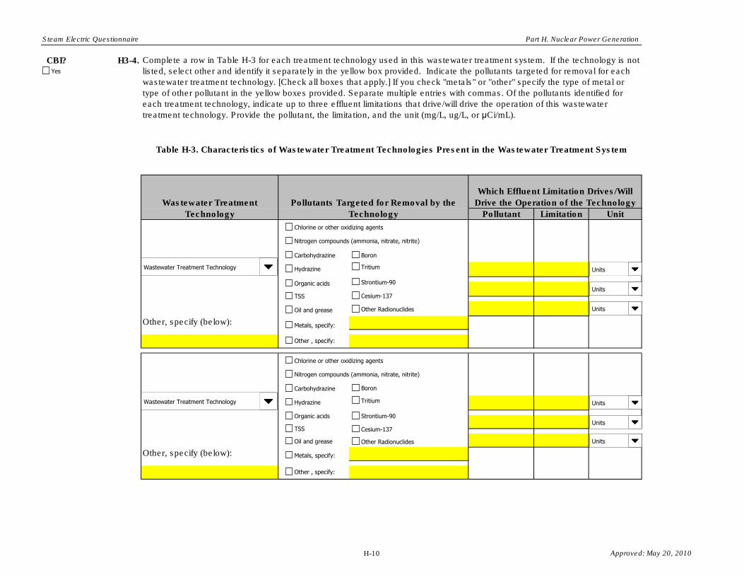
Steam Electric Questionnaire Part H. Nuclear Power Generation
CBI? H3-4.
Pollutant Limitation Unit
Complete a row in Table H-3 for each treatment technology used in this wastewater treatment system. If the technology is not
listed, select other and identify it separately in the yellow box provided. Indicate the pollutants targeted for removal for each
wastewater treatment technology. [Check all boxes that apply.] If you check "metals" or "other" specify the type of metal or
type of other pollutant in the yellow boxes provided. Separate multiple entries with commas. Of the pollutants identified for
each treatment technology, indicate up to three effluent limitations that drive/will drive the operation of this wastewater
treatment technology. Provide the pollutant, the limitation, and the unit (mg/L, ug/L, or µCi/mL).
Table H-3. Characteristics of Wastewater Treatment Technologies Present in the Wastewater Treatment System
Wastewater Treatment
Technology
Pollutants Targeted for Removal by the
Technology
Which Effluent Limitation Drives/Will
Drive the Operation of the Technology
Other, specify (below):
Other, specify (below):
Wastewater Treatment Technology Units
Yes
TSS
Organic acids
Nitrogen compounds (ammonia, nitrate, nitrite)
Chlorine or other oxidizing agents
Hydrazine
Carbohydrazine
Metals, specify:
Cesium-137
Strontium-90
Boron
Tritium
Other , specify:
Oil and grease Other Radionuclides
Units
Units
Wastewater Treatment Technology Units
TSS
Organic acids
Nitrogen compounds (ammonia, nitrate, nitrite)
Chlorine or other oxidizing agents
Hydrazine
Carbohydrazine
Metals, specify:
Cesium-137
Strontium-90
Boron
Tritium
Other , specify:
Oil and grease Other Radionuclides
Units
Units
H-10 Approved: May 20, 2010

Steam Electric Questionnaire Part H. Nuclear Power Generation
Other, specify (below):
Other, specify (below):
Other, specify (below):
Wastewater Treatment Technology Units
TSS
Organic acids
Nitrogen compounds (ammonia, nitrate, nitrite)
Chlorine or other oxidizing agents
Hydrazine
Carbohydrazine
Metals, specify:
Cesium-137
Strontium-90
Boron
Tritium
Other , specify:
Oil and grease Other Radionuclides
Units
Units
Wastewater Treatment Technology Units
TSS
Organic acids
Nitrogen compounds (ammonia, nitrate, nitrite)
Chlorine or other oxidizing agents
Hydrazine
Carbohydrazine
Metals, specify:
Cesium-137
Strontium-90
Boron
Tritium
Other , specify:
Oil and grease Other Radionuclides
Units
Units
Wastewater Treatment Technology Units
TSS
Organic acids
Nitrogen compounds (ammonia, nitrate, nitrite)
Chlorine or other oxidizing agents
Hydrazine
Carbohydrazine
Metals, specify:
Cesium-137
Strontium-90
Boron
Tritium
Other , specify:
Oil and grease Other Radionuclides
Units
Units
H-11 Approved: May 20, 2010

Steam Electric Questionnaire Part H. Nuclear Power Generation
Other, specify (below):
Other, specify (below):
Other, specify (below):
Wastewater Treatment Technology Units
TSS
Organic acids
Nitrogen compounds (ammonia, nitrate, nitrite)
Chlorine or other oxidizing agents
Hydrazine
Carbohydrazine
Metals, specify:
Cesium-137
Strontium-90
Boron
Tritium
Other , specify:
Oil and grease Other Radionuclides
Units
Units
Wastewater Treatment Technology Units
TSS
Organic acids
Nitrogen compounds (ammonia, nitrate, nitrite)
Chlorine or other oxidizing agents
Hydrazine
Carbohydrazine
Metals, specify:
Cesium-137
Strontium-90
Boron
Tritium
Other , specify:
Oil and grease Other Radionuclides
Units
Units
Wastewater Treatment Technology Units
TSS
Organic acids
Nitrogen compounds (ammonia, nitrate, nitrite)
Chlorine or other oxidizing agents
Hydrazine
Carbohydrazine
Metals, specify:
Cesium-137
Strontium-90
Boron
Tritium
Other , specify:
Oil and grease Other Radionuclides
Units
Units
H-12 Approved: May 20, 2010

Steam Electric Questionnaire Part H. Nuclear Power Generation
CBI? H3-5. Is the plant currently constructing/installing or planning to begin constructing/installing by December 31, 2020 any additional
treatment technologies not mentioned in question H3-4 to the wastewater treatment system? If so, indicate in Table H-4 below
the type of technology and the pollutants the technology will target. [Check all boxes that apply.] If you check "metals" or
"other" specify the type of metal or type of other pollutant in the yellow boxes provided. Separate multiple entries with
commas.
Table H-4. Characteristics of Planned Wastewater Treatment Technologies
in the Wastewater Treatment System
Wastewater Treatment
Technology
Pollutants Targeted for Removal by the
Technology
Other, specify (below):
Other, specify (below):
Wastewater Treatment Technology
Metals, specify:
Other , specify:
Yes
TSS
Organic acids
Nitrogen compounds (ammonia, nitrate, nitrite)
Chlorine or other oxidizing agents
Hydrazine
Carbohydrazine
Cesium-137
Strontium-90
Boron
Tritium
Oil and grease Other Radionuclides
Wastewater Treatment Technology
Metals, specify:
Other , specify:
TSS
Organic acids
Nitrogen compounds (ammonia, nitrate, nitrite)
Chlorine or other oxidizing agents
Hydrazine
Carbohydrazine
Cesium-137
Strontium-90
Boron
Tritium
Oil and grease Other Radionuclides
H-13 Approved: May 20, 2010

Steam Electric Questionnaire Part H. Nuclear Power Generation
Other, specify (below):
Other, specify (below):
Wastewater Treatment Technology
Metals, specify:
Other , specify:
TSS
Organic acids
Nitrogen compounds (ammonia, nitrate, nitrite)
Chlorine or other oxidizing agents
Hydrazine
Carbohydrazine
Cesium-137
Strontium-90
Boron
Tritium
Oil and grease Other Radionuclides
Wastewater Treatment Technology
Metals, specify:
Other , specify:
TSS
Organic acids
Nitrogen compounds (ammonia, nitrate, nitrite)
Chlorine or other oxidizing agents
Hydrazine
Carbohydrazine
Cesium-137
Strontium-90
Boron
Tritium
Oil and grease Other Radionuclides
H-14 Approved: May 20, 2010

Steam Electric Questionnaire Part H. Nuclear Power Generation
CBI? H3-6.
CBI? H3-7.
Typical flow rate in 2009, gpm
Maximum flow rate in 2009, gpm
Duration of effluent transfers from treatment system in 2009, hpd
Frequency of effluent transfers from treatment system in 2009, dpy
If you indicated in question H3-6 that the ultimate destination of the treated process wastewater was to recycle part of it back
to the plant, but not all of it, indicate the typical and maximum flow rates during 2009 for the recycled part of the treated
process wastewater. In addition, provide the duration and frequency of the effluent transfers from the wastewater treatment
system in 2009 for the recycled portion of the treated process wastewater. If the flow rate in 2009 is not typical of previous
years, please note this in the "Part H Comments" tab at the end of part.
What is the ultimate destination of the treated process wastewater from this wastewater treatment system? If recycled,
indicate how the treated process wastewater is recycled. [Check all boxes that apply].
In cooling towers
As reactor coolant (BWR)
As primary coolant (PWR)
As secondary coolant (PWR)
Other specify:
Yes
Yes
Recycled back to a plant process. Please describe how the treated process wastewater is reused
Discharged to surface water following on-site treatment, including those located on non-adjoining property.
Transferred to publicly or privately owned treatment works
Transported to an offsite vendor waste processor
Transported to approved licensed burial ground
Other, explain:
Please provide the NPDES permitted outfall number (from Part A Section 2.2)
H-15 Approved: May 20, 2010

Steam Electric Questionnaire Part H. Nuclear Power Generation
Plant ID: Insert Plant ID
Plant Name: Insert Plant Name
Part: H
Section Title:
Instructions:
Question
Number
CBI?
CBI?
CBI?
CBI?
CBI?
CBI?
CBI?
CBI?
CBI?
CBI?
Cross reference your comments by question number and indicate the confidential status of your comment by checking the box
next to “Yes” under "CBI?" (Confidential Business Information).
Part H Comments
Comment
Yes
Yes
Yes
Yes
Yes
Yes
Yes
Yes
Yes
Yes
H-16 Approved: May 20, 2010

Steam Electric Questionnaire Part H. Nuclear Power Generation
CBI?
CBI?
CBI?
CBI?
CBI?
CBI?
CBI?
CBI?
CBI?
CBI?
CBI?
CBI?
CBI?
CBI?Yes
Yes
Yes
Yes
Yes
Yes
Yes
Yes
Yes
Yes
Yes
Yes
Yes
Yes
H-17 Approved: May 20, 2010

Steam Electric Questionnaire Part H. Nuclear Power Generation
Part H Drop Downs
Process Wastewater
Select
Auxiliary building sump/drain wastewater
Boiler blowdown
Boiler metal cleaning waste
Chemical and volume control system (CVCS) purge (PWR)
Condensate clean-up system purge (PWR)
Containment/drywell building sump/drain wastewater
Contaminated stormwater
Filter backwash
Ion exchange wastewater
Laboratory drain wastewater
Laundry wastewater
Leachate
Leaks from primary coolant system (PWR)
Leaks from radiological waste treatment system(s)
Leaks from reactor coolant system (BWR)
Loss of coolant accidents
Personnel and equipment decontamination wastewater
Primary coolant purge (PWR)
Reactor coolant purge (BWR)
Reactor water clean-up system purge (BWR)
Reverse osmosis reject water
Sample station drain wastewater
Secondary coolant purge (PWR)
Solidification process wastewater
Steam turbine cleaning washwater
Turbine building floor drain wastewater
Yard drain wastewater
Other (specify name and description)
Approved: May 20, 2010

Steam Electric Questionnaire Part H. Nuclear Power Generation
Process Wastewater Code
Select
NUC-1
NUC-2
NUC-3
NUC-4
NUC-5
NUC-6
NUC-7
NUC-8
NUC-9
NUC-10
NUC-11
NUC-12
NUC-13
NUC-14
NUC-15
NUC-16
NUC-17
NUC-18
NUC-19
NUC-20
NUC-21
NUC-22
NUC-23
NUC-24
NUC-25
NUC-26
NUC-27
NUC-28
NUC-29
NUC-30
NUC-31
NUC-32
NUC-33
NUC-34
NUC-35
NUC-36
Nonradioactive/Radioactive
Select
Nonradioactive
Radioactive
Approved: May 20, 2010

Steam Electric Questionnaire Part H. Nuclear Power Generation
Type of Process Wastewater
Select
Both radioactive and nonradioactive wastewater
Nonradioactive wastewater only
Radioactive wastewater only
Units
Select
mg/L
ug/L
µCi/mL
Wastewater Treatment Technology
Select
Aerobic biological reactor
Anaerobic biological reactor
Centrifugation
Chemical precipitation/flocculation
Constructed wetlands
Cross flow filtration
Degasification
Dechlorination
Evaporation
Hollow fiber filtration
Ion exchange
Ion exchange membrane
Ion-specific filtration
Neutralization
Oil/water separator
Oil skimming
Reverse osmosis
Settling pond
Settling tank
Slow sand filter
Specially-prepared activated carbon
Super absorbent polymers
Temporary storage for radionuclide decay
Ultrafiltration
Wet oxidation
Other specify
Approved: May 20, 2010

OMB Control Number: 2040-0281 Approval Expires: 05/31/2013
Plant ID: Insert Plant ID Plant Name: Insert Plant Name
• ~ s
Steam Electric Questionnaire
PART 1- ECONOMIC AND FINANCIAL DATA
Table of Contents
Section Title
Part I Instructions Immediate Parent Economic and Financial
Information Primary Immediate Parent Firm Economic and
Financial Information Ultimate Parent Economic and Financial Information Basic Plant Economic and Financial Information Detailed Plant Financial Information Basic Steam Electric Generating Unit Economic and
Financial Information Steam Electric Generating Unit Operating Information Planned and Forced Outages and Annual Operating Cost Part I Comments
Tab Name
Part I Instructions Part I Section 1
Part I Section 2
Part I Section 3 Part I Section 4.1 Part I Section 4.2 Part I Section 5.1
Part I Section 5.2 Part I Section 5.3 Part I Comments
Approved: May 20, 2010

Steam Electric Questionnaire Part I. Instructions
Plant ID: Insert Plant ID Plant Name: Insert Plant Name
PART I. ECONOMIC AND FINANCIAL DATA
INSTRUCTIONS
Complete Part I of the questionnaire for your plant. As you are completing the electronic form, note the following: When you enter your plant name and plant ID on the Part I TOC tab, all name and ID fields throughout Part I will automatically populate. Refer to the overall questionnaire instructions and the list of abbreviations for additional assistance with completing Part I. Refer to the glossary for definitions of selected economic and financial terms used in this Part.
You may wish to assemble the following documents in order to efficiently fill out this part of the questionnaire:
(1) For the entity/entities that own your plant: income statements, balance sheet statements, and cash flow statements for the last three fiscal years.
(2) For your plant: data on electricity generated, operating expenses, income statement, balance sheet, and other operational statements for the last three fiscal years of operation.
Please provide all free response answers in the highlighted yellow areas.
Use the Part I Comments tab to do the following: provide additional information as requested in certain questions within Part I; indicate atypical data (e.g., if the analytical data provided from the sample collection is not representative of normal operations); and note methods used to make estimates based on professional judgment in the event that exact data are not available.
In cases where a plant has multiple immediate parent firms and where it is not possible to identify a primary parent firm based on equity share, you may make copies of Section 2 of this questionnaire and provide the requested information for each immediate parent listed in Section 1.
Approved: May 20, 2010

Steam Electric Questionnaire Part I. Economic and Financial Data
CBI? DYes
Part: I Section Title: 1. Immediate Parent Economic and Financial Information
Plant ID: Insert Plant ID Plant Name· Insert Plant Name
Instructions: Throughout Section 1, provide financial information for the immediate parent firm or, in case where multiple entities have financial participation or interest in the plant , for every entity with an equity stake (or any other form of financial participation or interest) in this plant. For the purpose of this questionnaire, the immediate parent is the first entity in the plant's ownership structure. A plant may have more than one immediate parent if more than one firm owns or has another form of financial participation or interest in the generating units located at the plant. Please provide all free response answers in the highlighted yellow areas.
11-1 . In Table 1-1 , provide the following information for the immediate parent firm or, in case where multiple entities have financial participation or interest in the plant, for every entity with an equity stake (or any other form of financial participation or interest) in this plant. If the financial participation shares vary by generating units at the plant, please estimate the plant-level share based on the relative electricity generation capacity (nameplate capacity) of all units at this plant.
Table 1-1. Immediate Parent Firm Financial Information
Fiscal Year %
Ownership Revenue or Financial from
Name of Interest in Total Electricity Immediate Mailing Plant in DUNS Revenue Generation Total Employment Total Electricity
Number Parent Address 2009 NAICS Number Start(mm) End (mm) Year ('000$) ('000$) (FTE) Sales (MWh)
2007 1200000 800000 11,000-1,249 ... 15 400 400 123A
11,000·1,249 Street, 2008 1 560 000 851000 ...
15 851 700 City, State,
I• I• 11,250·1,499 Example ABCLLC ZIP 34.50% 2211 123456789 January December 2009 1 720 000 867000 ... 15 110 890
12500, 2007 552,000 502800 1250·499 ... 6,570000 Some 2008 550,000 513,100 1250·499 ... 6,858000
Blvd., City, 1 ... 1 Example EFGinc. State, ZIP 45% 2211 587426985 January I• December I• 2009 487000 479200 250·499 6 253000
789Z 2007 126 000 20000 250-499 250 1 ... 1 235 200 Street, 2008 120 000 10000 250-499 265 1 ... 1 259100
City, State, l ... J Example XYZCorp. ZIP 20.50% 2211 925486982 April l · March l · 2009 89000 11,500 100·249 207 231.985
2007 Select 1 ... 1
2008 Select 1 ... 1
1 Select I• Select I• 2009 Select 1 ... 1
2007 Select 1 ... 1
2008 Select l ... J 2 Select I• Select I• 2009 Select
1 ... 1
2007 I Select ~ 2008 I Select ~
3 Select I· Select I· 2009 I Select 1 ... 1
1-1 Approved: May 20, 2010

Steam Electric Questionnaire Part I. Economic and Financial Data
Plant ID: Insert Plant ID Plant Name: Insert Plant Name
Part: I Section Title : 2. Primary Immediate Parent Firm Economic and Financial Information
Instructions: Throughout Section 2, EPA is interested in obtaining financial and economic data regarding the plant owner to support a detailed evaluation of the economic impacts of the regulations on firms that own steam electric power generation assets. When answering questions in Section 2, please provide data for the immediate parent firm and not only for the steam electric plant covered in this questionnaire.
If the plant has multiple owners (immediate parent firms identified in Question 11-1 ), please report detailed information in Questions 12-1 through 12-13 only for the entity that has the largest equity stake (or the largest share of financial participation or interest) in the steam electric portion of the plant. This immediate parent firm is referred to as the "primary immediate parent" firm in the remainder of this section.
For example, a hypothetical steam electric plant has three generation units, two of which are steam. Table 1-2 below provides the distribution of plant capacity and ownership shares for this plant. Since ABC LLC has the largest ownership share in the steam electric capacity at this hypothetical plant, the detailed information requested in the remainder of this section would be provided for ABC LLC.
Table 1-2. Distribution of Plant Capacity and Ownership Shares for Example Plant
Plant Unit 1 (non-steam) Unit 2 (steam) Unit 3 (steam) % of Plant Total
Capacity 45% 35% 20% Ownership Share of Immediate Ownership Share Plant Steam Electric parent firm Capacity(1)
EFG Inc. 100% 0% ABCLLC. 70% 50% 63% XYZ Corp. 30% 50% 37% ('l details of ownership share calculations:
EFG Inc. share: 0% since only has shares in non-steam generation capacity.
ABC LLC share: 0. 70 x 0.35 I (0.35+0.20) + 0.50 x 0.20 I (0.35+0.20) = 0.63
XYZ Corp. share: 0.30 x 0.35 I (0.35+0.20) + 0.50 x 0.20 I (0.35+0.20) = 0.37
In cases where a plant has multiple immediate parent firms and where it is not possible to identify a primary parent firm based on equity shares, you may make copies of Section 2 of this questionnaire, using the "Copy Section 2" button below, and provide the requested information for each immediate parent listed in Section 1. In the example above, you have the option of providing information for both ABC LLC and XYZ Corp.
1-2 Approved: May 20, 2010

Steam Electric Questionnaire Part I. Economic and Financial Data
CBI?
DYes
12-1. Please select the primary immediate parent firm for which you are providing detailed information in this section. (Lists immediate parent firm(s) provided in Question 11-1)
I Select
1-3 Approved: May 20, 2010

Steam Electric Questionnaire Part I. Economic and Financial Data
CBI?
DYes
CBI?
DYes
CBI?
DYes
CBI?
DYes
12-2. Please indicate the type of ownership for the primary immediate parent firm.
• Other, specify:
12-3. Please indicate the state in which the primary immediate parent firm is organized as a legal entity.
12-4. Please indicate the legal structure of the plant's ownership.
• 12-5. Has the primary immediate parent firm engaged in revenue generating activities other than electricity generation during the period of FY 2007 through
FY 2009?
NOTE: Economic activities other than generation of electricity may include, but are not limited to, production activities or the leasing of land. Please include only those economic activities that are carried out by the plant's owner; do not include activities carried out on the plant's property by third parties for which the plant's owner does not incur cost or receive revenue.
0Yes
0No
(Continue to Question 12-5) (Skip to Question 12-6)
1-4 Approved: May 20, 2010

Steam Electric Questionnaire Part I. Economic and Financial Data
CBI?
DYes
CBI?
DYes
12-6. Please provide a description of each of the entity's revenue generating activities other than generation of electricity and the revenue and costs associated with this(ese) activity(ies).
Table 1-3. Description of Each Entity's Other Revenue Generating Activities
FY Description of Economic Activity Revenue ('000$) Costs ('000$) Economic activities not associated with electricity generation (e.g. , manufacturing production , leasing of land)
2007 2008 2009
12-7. Has the immediate parent firm submitted data to FERC in Form 1 for the period of FY 2007 through FY 2009? FERC Form No. 1 (FERC Form 1) is an annual regulatory requirement for Major electric utilities, licensees and others (18 C.F.R. § 141.1) and is designed to collect financial and operational information from electric utilities, licensees and others subject to the jurisdiction of the Federal Energy Regulatory Commission. If you answer YES, please attach a copy of your FERC Form 1 report for 2009 in pdf format to your submittal to ensure that EPA has the most recent data for your firm. EPA will also be using the data you already reported on your FERC Form 1 filing for 2007 and 2008 to support its economic impact and other analyses.
0 Yes, attach FERC Form 1. (Skip to Question 12-12)
D FERC Form 1 is NOT attached. Explain why:
0No (Continue to Question 12-7)
1-5 Approved: May 20, 2010

Steam Electric Questionnaire Part I. Economic and Financial Data
CBI?
Dves
CBI?
DYes
12-8. In Table 1-4, please provide the income statement information for the immediate parent firm. This information may be available from SEC filings, depending on how the firm presents its statement, if your immediate parent firm is a publicly traded company.
Table 1-4. Income Statement Information
FY 2007 FY 2008 FY 2009 Total revenue ('000$)
Revenue from electric power generation and sales Revenue from sources indirectly related to the generation of electricity (e.g. , sale of steam or ash, waste combustion)
Other revenue (i.e., total revenue from activities described in Question 12-5)
Total expenses ('000$) Operation expenses Maintenance expenses Depreciation, depletion, and amortization expense Interest expense (Total. Firms with debt should have interest expenses)
Income taxes (Total federal , state, and local income taxes)
All other expenses (i.e. including total cost of activities described in Question 12-5)
After-tax income (Subtract Total operating expenses from Total revenue)
12-9. In Table 1-5, please provide the following balance sheet information for the immediate parent firm. This information may be available from SEC filings, depending on how the firm presents its statement, if your immediate parent firm is a publicly traded company.
Table 1-5. Balance Sheet Information
FY 2007 FY 2008 FY 2009 Assets ('000$) Inventories (Raw materials, supplies, fuels, etc.) Other current assets (Prepared expenses, cash , accounts receivable, etc.
Non-current assets (land, buildings, equipment, machinery, other physical capital and intangibles, capital stocks and bonds, etc. , including expansions and renovations and net of depreciation and amortization)
Liability/Equity ('000$) Current liabilities (Liabilities due for payment within the reporting year)
Non-current liabilities (Including long-term debt, such as bonds, debentures, and bank debt)
Owner equity (Total assets minus total (current and non-current) liabilities)
1-6 Approved: May 20, 2010
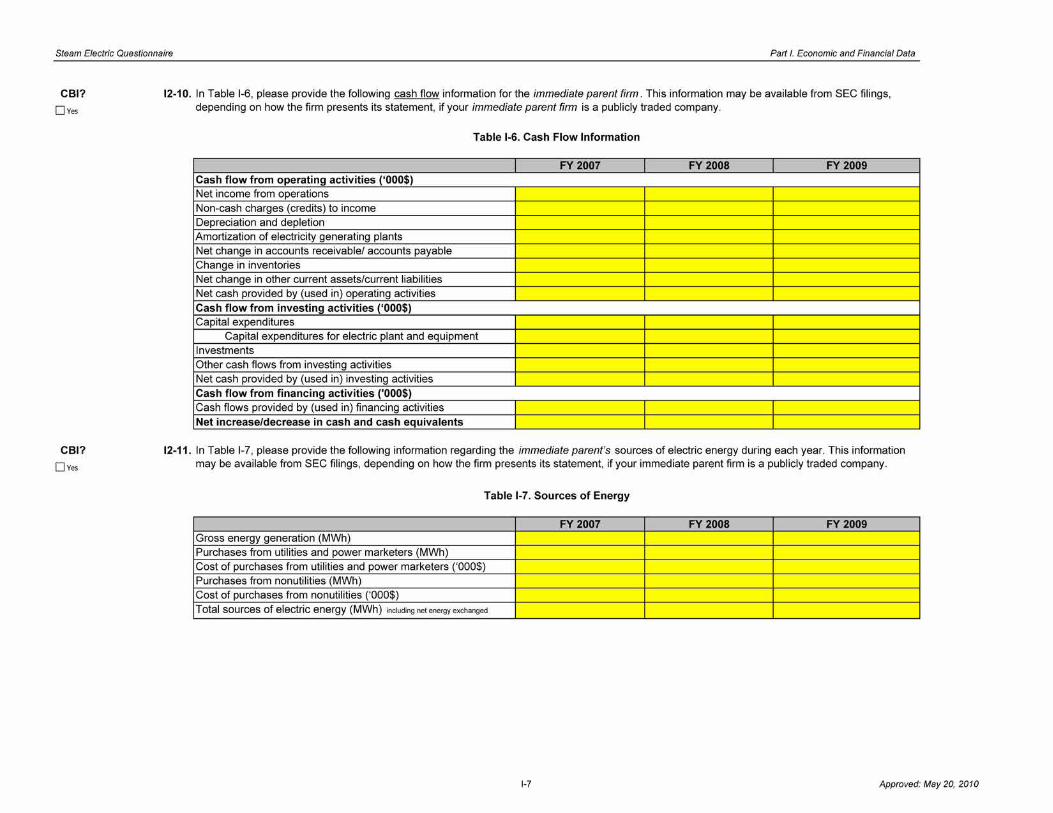
Steam Electric Questionnaire Part I. Economic and Financial Data
CBI?
DYes
CBI?
Dves
12-10. In Table 1-6, please provide the following cash flow information for the immediate parent firm. This information may be available from SEC filings, depending on how the firm presents its statement, if your immediate parent firm is a publicly traded company.
Table 1-6. Cash Flow Information
FY 2007 FY 2008 FY 2009 Cash flow from operating activities ('000$) Net income from operations Non-cash charges (credits) to income Depreciation and depletion Amortization of electricity generating plants Net change in accounts receivable/ accounts payable Change in inventories Net change in other current assets/current liabilities Net cash provided by (used in) operating activities Cash flow from investing activities ('000$) Capital expenditures
Capital expenditures for electric plant and equipment Investments Other cash flows from investing activities Net cash provided by (used in) investing activities Cash flow from financing activities ('000$) Cash flows provided by (used in) financing activities Net increase/decrease in cash and cash equivalents
12-11. In Table 1-7, please provide the following information regarding the immediate parent's sources of electric energy during each year. This information may be available from SEC filings, depending on how the firm presents its statement, if your immediate parent firm is a publicly traded company.
Table 1-7. Sources of Energy
FY 2007 FY 2008 FY 2009 Gross energy generation (MWh) Purchases from utilities and power marketers (MWh) Cost of purchases from utilities and power marketers ('000$) Purchases from nonutilities (MWh) Cost of purchases from nonutilities ('000$) Total sources of electric energy (MWh) including net energy exchanged
1-7 Approved: May 20, 2010

Steam Electric Questionnaire Part I. Economic and Financial Data
CBI?
DYes
CBI?
DYes
CBI?
DYes
12-12. In Table 1-8, please provide the following information regarding the immediate parent's disposition of electric energy generated, purchased, exchanged, and wheeled during each year. This information may be available from SEC filings, depending on how the firm presents its statement, if your immediate parent firm is a publicly traded company.
Table 1-8. Disposition of Electricity
FY 2007 FY 2008 FY 2009 Sales for resale (MWh) Revenue from sales for resale ('000$) Sales to end users (MWh) Revenue from sales to end users ('000$) Electric energy furnished without charge (MWh) Electric energy used by the parent (MWh) Total uses of electric energy (MWh) including energy losses
12-13. In Table 1-9, please provide the following information regarding the fraction of the immediate parent's electricity sales (on a MWh basis) subject to different pricing terms.
NOTE: EPA is looking for information regarding the approximate share of electricity that is sold under various terms and conditions to help in conducting economic impact and other types of analyses. You may provide approximate shares based on information readily available from immediate parent's filings and statements.
Table 1-9. Electricity Sales
Example FY 2007 FY 2008 FY 2009 % sales subject to cost-of-service based regulated pricing 60% % % % % contracted sales 30% % % % % sales subject to short-term auction pricing 10% % % % TOTAL 100% 0% 0% 0%
12-14. If the share of contracted sales indicated in Question 12-12 is greater than 0% in FY2009, please indicate in Table 1-10 the approximate shares of the immediate parent firm 's contracted electricity sales (on a MWh basis) that are of different durations and terms.
Table 1-10. Approximate shares of the Immediate Parent's Contracted Electricity Sales
Example FY 2009 % contracted sales in FY 2009 subject to contract pricing under contracts of one year or less duration. 80% % % sales in FY 2009 subject to contract pricing under contracts more than one year in duration 20% %
Contracted sales under contracts more than one year in [!]None DNone
duration that include clauses permitting price adjustments D AII DAII
based on changes in environmental regulatory D Other, specify: % D Other, specify: I %
1-8 Approved: May 20, 2010

Steam Electric Questionnaire Pari /. Economic and Financial Data
CBI?
D ves
CBI?
D ves
Part: I Section Title: 3. Ultimate Parent Economic and Financial Information
Plant ID: Insert Plant ID Plant Name· Insert Plant Name
Instructions: Throughout Section 3, please provide information for the ultimate parent firm of each immediate parent firm identified in Question 11-1 or, in case of joint ownership or partnership in the immediate parent firm , for the entity having the largest equity stake in the immediate parent firm. Please provide all free response answers in the highlighted yellow areas.
For the purpose of this questionnaire, the ultimate parent firm is the highest level domestic business entity in a plant's ownership structure. A firm that is owned by another U.S. firm is not an ultimate domestic parent firm. In contrast, a U.S. firm that is owned by a foreign firm is an ultimate domestic parent firm.
NOTE: EPA is interested in financial information about ultimate parent firm of entity(ies) that own or have financial participation or interest in your plant to conduct regulatory and economic impact analyses and to identify the relevant firm size category for corporate entities potentially affected by the regulations.
13-1 . Is (are) the ultimate parent firm(s) the same as the immediate parent(s) identified in Question 11-1?
0 Yes
0No
(Skip to Section 4.1)
(Continue to Question 13-2)
13-2. In Table 1-11 , please provide the following information for the ultimate parent firm of each immediate parent firm identified in Question 11-1 or, in case of joint ownership or partnership in the immediate parent firm , for the entity having the largest equity stake in the immediate parent firm . If the ultimate parent firm is the same as the immediate parent firm , you may indicate so in column 2 and do not need to provide the information requested in columns 3 through 10 of the table. This information may be available from SEC filings, if your ultimate parent firm is a publicly traded company.
Table 1-11 . Ultimate Parent Firm Financial Information
%Financial Immediate Interest in Fiscal Year Total
Parent (from Name of Ultimate Mailing Immediate Total Revenue Employment Total Electricity Question 1-1) Parent Address Parent in 2009 NAICS DUNS Number Start(mm) End(mm) Year ('000$) (FTE) Sales (MWh)
EFG/nc. 2007
0 Same as Immediate Parent 2008 Select l· Select l· 2009
ABC LLC. U.S. DIAMOND CORP 2255 5'h 2007 52,358,000 25,875 45,400,400
0 Same as Immediate Parent Avenue, City,
2008 55,582,000 25,786 45 851 700 State, ZIP
I• I• 85% 5239 885785963 Octo bee September 2009 56,889,200 26,850 55,110,890
XVZCorp. 2007
0 Same as Immediate Parent 2008
Select l· Select l· 2009
Select I• 2007
D Same as Immediate Parent 2008
Select I• Select I• 2009
Select I· 2007
D Same as Immediate Parent 2008
Select I• Select I• 2009
Select I• 2007
D Same as Immediate Parent 2008
Select I• Select I• 2009
1-8 Approved: May 20, 2010

Steam Electric Questionnaire Patti. Economic and Financial Data
CBI?
DYes
CBI?
DYes
CBI?
DYes
Part: I Section Title: 4.1 Basic Plant Economic and Financial Information
Plant ID: Insert Plant ID Plant Name: Insert Plant Name
Instructions: Throughout Section 4.1, please provide the requested economic and financial information for the plant . Please provide all free response answers in the highlighted yellow areas.
NOTE: For Section 4.1, EPA is interested in obtaining financial and economic data regarding the specific plant covered by this questionnaire.
14-1. What is the Fiscal Year period covered by plant-level financial and operational information provided in this section?
Start (dd/mm)
End (dd/mm)
14-2. In Table 1-12, please indicate the number of months in each fiscal year for which you have financial and operational information for your plant . In some cases, such as new plants, records may cover only part of a year.
Table 1-12. Number of Months in Each Fiscal Year
I Number of Months IFY 2007 FY 2008 FY 2009
14-3. At any time during the three reporting years, did the plant engage in revenue generating activities other than generation of electricity?
NOTE: Economic activities other than generation of electricity may include, but are not limited to, production activities or the leasing of land. Please include only those economic activities that are carried out by the plant's owner; do not include activities carried out on the plant's property by third parties for which the plant's owner does not incur cost or receive revenue. If such third party activities are significant, you may note them in the comments section at the end of Part I.
0Yes
0No
(Continue to Question 14-4)
(Skip to Question 14-7)
1-9 Approved: May 20, 2010
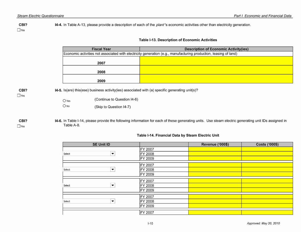
Steam Electric Questionnaire Patti. Economic and Financial Data
CBI? DYes
CBI? DYes
CBI?
DYes
14-4. In Table A-13, please provide a description of each of the plant's economic activities other than electricity generation.
Table 1-13. Description of Economic Activities
Fiscal Year Description of Economic Activity(ies) Economic activities not associated with electricity generation (e.g., manufacturing production , leasing of land)
2007
2008
2009
14-5. ls(are) this(ese) business activity(ies) associated with (a) specific generating unit(s)?
0Yes
0No
(Continue to Question 14-6)
(Skip to Question 14-7)
14-6. In Table 1-14, please provide the following information for each of these generating units. Use steam electric generating unit IDs assigned in Table A-8.
Table 1-14. Financial Data by Steam Electric Unit
SE Unit ID Revenue ('000$) Costs ('000$) FY 2007
Select 1 .... 1 FY 2008 FY 2009
FY 2007 Select 1 .... 1 FY 2008
FY 2009
FY 2007 Select R FY 2008
FY 2009
FY 2007 Select 1 .... 1 FY 2008
FY 2009
FY 2007
1-10 Approved: May 20, 2010

Steam Electric Questionnaire Patti. Economic and Financial Data
CBI?
D Yes
CBI? D Yes
CBI?
DYes
Select l ... J FY 2008 FY 2009
FY 2007 Select 1 ... 1 FY 2008
FY 2009
14-7. In Table 1-15, please provide information on total plant employment in terms of full-time equivalent employees (FTE).
Table 1-15. Plant Employment Information
FY 2007 FY 2008 FY 2009 Total Employment (FTE)
14-8. In Table 1-16, please provide gross and net electricity generated by the plant on a fiscal year basis.
NOTE: If your fiscal year coincides with the calendar year, please indicate so below and skip this question. The requested information is already provided in Question A1-14 of questionnaire on a calendar year basis.
D This plant's fiscal year coincides with calendar years (i.e., fiscal year period is January 1 -December 31 ). Refer to answer to Question A 1-14 for the requested data.
Table 1-16. Gross and Net Electricity Generated by Plant
FY 2007 FY 2008
Gross Electricity Generated (MWh)
Net Electricity Generated (MWh)
14-9. In Table 1-17, please provide information regarding capital outlays for plant and equipment for the plant .
Table 1-17. Capital Outlays for Plant
FY 2007 FY 2008 Capital outlays for plant and equipment ('000$)
FY 2009
FY 2009
1-11 Approved: May 20, 2010

Steam Electric Questionnaire Part I. Economic and Financial Data
CBI?
D ves
Part: I Section Title: 4.2 Detailed Plant Financial Information
Plant ID: Insert Plant ID Plant Name: Insert Plant Name
Instructions: In Section 4.2, please provide financial information for the plant . Your parent firm may not customarily compile financial reports at the level of the plant. In that case, you may estimate plant-level information from data reported at the level of reporting closest to your plant This may be a division, the immediate parent firm, or some other business unit. You should report information about your plant either from existing reports or by estimating plant-level data. If you have to estimate plant-level data, you may use any method and information that, in your judgment, will yield the best estimate of plant-level data and describe the method in Question 14-12. If no such method or information is available, you may follow the default methodology outlined below.
Default Methodology: Please estimate plant-level data by using aggregate data from the financial reports for the business unit that is closest to your plant in terms of business activity performed. Please estimate plant data by multiplying that business unit's numbers corresponding to electricity generation activities by the ratio of your plant's net generation to the business unit's net generation. For example, if you have aggregate data for a business unit consisting of three plants, each with 100 MWh in net generation, the plant-level data are estimated based on 1/3 of the aggregate data.
14-10. In Table 1-18, please provide the following balance sheet information for the plant. As needed, you may estimate plant-level data based on balance sheet information for the relevant business unit or immediate parent.
D Plant-level balance sheet data have been estimated for the purpose of answering this questionnaire. Provide details in Question 14-12.
Table 1-18. Balance Sheet Information for Plant
FY 2007 FY 2008 FY 2009 Assets ('000$) Inventories (Raw materials, supplies, fuels , etc.) Other current assets (Prepared expenses, cash , accounts receivable, etc. Land and buildings (Original land cost and cost of buildings, including expansions and renovations, net of depreciation)
1-13 Approved: May 20, 2010

Steam Electric Questionnaire Part I. Economic and Financial Data
CBI?
DYes
Other non-current assets (Equipment, machinery, other physical capital and intangibles, capital stocks and bonds, etc., net of depreciation and amortization)
Liability/Equity ('000$) Current liabilities (Liabilities due for payment within the reporting year)
Non-current liabilities (Including long-term debt, such as bonds, debentures, and bank debt) Owner equity (Total assets minus total (current and non-current) liabilities
14-11. In Table 1-19, please provide the following income statement information for the plant . As needed, you may estimate plant-level data based on income statement information for the relevant division, business unit or immediate parent.
D Plant-level income statement data have been estimated for the purpose of answering this questionnaire. Provide details in Question 14-12.
Table 1-19. Income Statement for Plant
FY 2007 FY 2008 FY 2009 Total revenue ('000$)
Revenue from electric power generation and sales
Revenue from sources indirectly related to the generation of electricity (e.g ., sale of steam or ash, waste combustion)
Other revenue (i.e., total revenue from the economic activities described in Question 14-4) (describe below)
Total expenses ('000$) Fuel expenses Other operating expenses Total maintenance expenses Total sales and customer accounts, service, and informational expenses Cost of contract work Interest expense Taxes
1-14 Approved: May 20, 2010
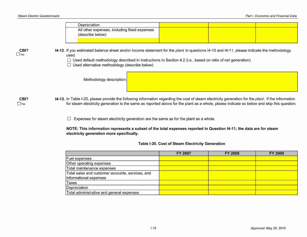
Steam Electric Questionnaire Part I. Economic and Financial Data
CBI? DYes
CBI? DYes
Depreciation All other expenses, including fixed expenses (describe below)
14-12. If you estimated balance sheet and/or income statement for the plant in questions 14-10 and 14-11, please indicate the methodology used. D Used default methodology described in Instructions to Section 4.2 (i.e., based on ratio of net generation) D Used alternative methodology (describe below)
Methodology description:
14-13. In Table 1-20, please provide the following information regarding the cost of steam electricity generation for the plant . If the information for steam electricity generation is the same as reported above for the plant as a whole, please indicate so below and skip this question.
D Expenses for steam electricity generation are the same as for the plant as a whole.
NOTE: This information represents a subset of the total expenses reported in Question 14-11; the data are for steam electricity generation more specifically.
Table 1-20. Cost of Steam Electricity Generation
FY 2007 FY 2008 FY 2009 Fuel expenses Other operating expenses Total maintenance expenses Total sales and customer accounts, services, and informational expenses Taxes Depreciation Total administrative and general expenses
1-15 Approved: May 20, 2010

Steam Electric Questionnaire Part I. Economic and Financial Data
CBI?
DYes
Part: I Section Title : 5.1 Basic Steam Electric Generating Unit Economic and Financial Information
Plant ID: Insert Plant ID Plant Name· Insert Plant Name
Instructions: Please provide the economic and financial information requested for each steam electric generating unit at your plant . Use steam electric generating unit IDs assigned in Table A-8. Please provide all free response answers in the highlighted yellow areas.
15-1 . In Table 1-21 , please provide information for each non-retired (as of January 1, 2007) steam electric generating unit of your plant. Use steam electric generating unit IDs assigned in Table A-8.
NOTE: If a generating unit is owned by more than one entity, please provide the name(s) of the immediate parent firm(s) and their respective equity shares (or financial participation or interest) in this generating unit.
Table 1-21 . Basic Financial Steam Electric Generating Information
Immediate parent SE Unit ID Remaining undepreciated value ('000$) firm(s) in 2009 Nonutility status of each steam electric generating unit
D Cogenerator
D FERC qualifying cogenerator
FY2007 250,000 ABC LLC. (70%)
D FERC qualifying small power producer
Example D FERC exempt wholesale generator
FY2008 225,000 XYZ Corp. (30%)
D Cogenerator not qualified under PURPA
D Other (specify):
FY2009 200,000 0 Check here if not applicable
D Cogenerator
D FERC qualifying cogenerator
FY 2007 D FERC qualifying small power producer
Select I"" D FERC exempt wholesale generator
FY 2008 D Cogenerator not qualified under PURPA
D Other (specify):
FY 2009 D Check here if not applicable
D Cogenerator
D FERC qualifying cogenerator
FY 2007 D FERC qualifying small power producer
Select l"" D FERC exempt wholesale generator
FY 2008 D Cogenerator not qualified under PURPA
D Other (specify):
FY 2009 D Check here if not applicable
D Cogenerator
D FERC qualifying cogenerator
FY 2007 D FERC qualifying small power producer
Select I"" D FERC exempt wholesale generator
FY 2008 D Cogenerator not qualir under PURPA
D Other (specify):
FY 2009 D Check here if not applicable
D Cogenerator
D FERC qualifying cogenerator
FY 2007 D FERC qualifying small power producer -. I _ ~
1-16 Approved: May 20, 2010

Steam Electric Questionnaire Part I. Economic and Financial Data
Select I"" D FERC exempt wholesale generator
FY 2008 D Cogenerator not qualified under PURPA
D ather (specify): r FY 2009 D Check here if not applicable
D Cogenerator
D FERC qualifying cogenerator
FY 2007 D FERC qualifying small power producer
Select 1 ....
D FERC exempt wholesale generator
FY 2008 D Cogenerator not qualir under PURPA
D Other (specify):
FY 2009 D Check here if not applicable
D Cogenerator
D FERC qualifying cogenerator
FY 2007 D FERC qualifying small power producer
Select I .... D FERC exempt wholesale generator
FY 2008 D Cogenerator not qualified under PURPA
D Other (specify):
FY 2009 D Check here if not applicable
D Cogenerator
D FERC qualifying cogenerator
FY 2007 D FERC qualifying small power producer
Select 1 ....
D FERC exempt wholesale generator
FY 2008 D Cogenerator not qualir under PURPA
D Other (specify):
FY 2009 D Check here if not applicable
D Cogenerator
D FERC qualifying cogenerator
FY 2007 D FERC qualifying small power producer
Select l""' D FERC exempt wholesale generator
FY 2008 D Cogenerator not qualified under PURPA
D ather <specify): r FY 2009 D Check here if not applicable
D Cogenerator
D FERC qualifying cogenerator
I Select 1 .... 1
FY 2007 D FERC qualifying small power producer
D FERC exempt wholesale generator
FY 2008 D Cogenerator not qualified under PURPA
D Other (specify):
FY 2009 D Check here if not applicable
D Cogenerator
D FERC qualifying cogenerator
FY 2007 D FERC qualifying small power producer
Select l .... D FERC exempt wholesale generator
FY 2008 D Cogenerator not qualified under PURPA
D Other (specify):
FY 2009 D Check here if not applicable
1-17 Approved: May 20, 2010
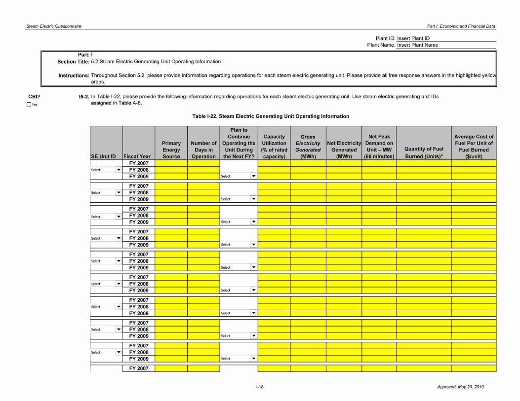
Steam Electric Questionnaire Part I. Economic and Financial Data
CBI?
Dves
Part: I Section Title : 5.2 Steam Electric Generating Unit Operating Information
Plant ID: Insert Plant ID Plant Name· Insert Plant Name
Instructions: Throughout Section 5.2, please provide information regarding operations for each steam electric generating unit. Please provide all free response answers in the highlighted yello'A areas.
15-2. In Table 1-22, please provide the following information regarding operations for each steam electric generating unit. Use steam electric generating unit IDs assigned in Table A-8.
Table 1-22. Steam Electric Generating Unit Operating Information
Plan to Continue Capacity Gross Net Peak
Primary Number of Operating the Utilization Electricity Net Electricity Demand on Energy Days in Unit During (%of rated Generated Generated Unit-MW Quantity of Fuel
SE Unit ID Fiscal Year Source Operation the Next FY? capacity) (MWh) (MWh) (60 minutes) Burned (Units)" FY 2007
Select l ... FY 2008 FY 2009 Select l ... FY 2007
Select 1 ... FY 2008 FY 2009 Select 1 ...
FY 2007
Select 1 ... FY 2008 FY 2009 Select 1 ...
FY 2007 Select 1 ... FY 2008
FY 2009 Select 1 ...
FY 2007 Select 1 ... FY 2008
FY 2009 Select l ... FY 2007
Select l ... FY 2008 FY 2009 Select l ... FY 2007
Select 1 ... FY 2008 FY 2009 Select 1 ...
FY 2007 Select 1 ... FY 2008
FY 2009 Select 1 ...
FY 2007 Select 1 ... FY 2008
FY 2009 Select l ... FY 2007
Average Cost of Fuel Per Unit of
Fuel Burned ($/unit)
1-18 Approved: May 20, 2010

Steam Electric Questionnaire Part I. Economic and Financial Data
I Select I "' 11 FY 2008 I I FY 2009 Select I "' ]
a- (coal in tons of 2,000 lbs; oil in barrels of 42 gals; gas in mcf; nuclear or other- indicate)
1-19 Approved: May 20, 2010

Steam Electric Questionnaire Parll. Economic and Financial Data
CBI? DYes
Part: I Section Title: 5.3 Planned and Forced Outages and Annual Operating Cost
Plant ID: Insert Plant ID Plant Name: Insert Plant Name
Instructions: In Section 5.3, please provide information on the duration of planned and forced outages and annual operating cost for each steam electric generating unit. Please provide all free response answers in the highlighted yellow areas.
15-3. In Table 1- 23, please provide information on the duration of planned and forced outages for each steam electric generating unit. Use steam electric generating unit IDs assigned in Table A-8.
Table 1-23. Planned and Forced Outages
Total Duration of
Total Duration of Outages Planned/ Duration of Planned/Scheduled Scheduled to Address Forced/Unscheduled
Routine Maintenance Major Upgrades a Outages for this Unit SE Unit ID Fiscal Year Outages (hours/year) (hours/year) (hours/year)
FY 2007 Select 1 ...
FY 2008 FY 2009
FY 2007 Select 1 ... FY 2008
FY 2009
FY 2007 Select 1 ... FY 2008
FY 2009
FY 2007 Select 1 ... FY 2008
FY 2009
FY 2007 Select 1 ... FY 2008
FY 2009
1-19 Approved: May 20, 2010

Steam Electric Questionnaire Parll. Economic and Financial Data
FY 2007 Select 1 ...
FY 2008 FY 2009
FY 2007 Select 1 ... FY 2008
FY 2009
FY 2007 Select 1 ...
FY 2008 FY 2009
FY 2007 FY 2008 FY 2009
FY 2007 FY 2008 FY 2009
a- Such as repowering, FGD/SCR installation, etc.
1-20 Approved: May 20, 2010

Steam Electric Questionnaire Parll. Economic and Financial Data
CBI? Dves
15-4. In Table 1-24, please provide the following annual operating cost information for each generating unit (refers to steam electric generating unit IDs assigned in Table A-8, as entered in Question 15-3).
Table 1-24. Annual Operating Cost
SE Unit ID Fiscal Year Total Costs ($)a Fuel Costs ($) Variable O&M Costs ($) b
Select FY 2007 FY 2008 FY 2009
Select FY 2007 FY 2008 FY 2009
Select FY 2007 FY 2008 FY 2009
Select FY 2007 FY 2008 FY 2009
Select FY 2007 FY 2008 FY 2009
Select FY 2007 FY 2008 FY 2009
Select FY 2007 FY 2008 FY 2009
1-21 Approved: May 20, 2010

Steam Electric Questionnaire Parll. Economic and Financial Data
Select FY 2007 FY 2008 FY 2009
Select FY 2007 FY 2008 FY 2009
Select FY 2007 FY 2008 FY 2009
a- Total costs may include other operating costs (other than fuel costs or variable O&M) such as the scheduled maintenance of boiler and electric plant and the scheduled maintenance of generating and electric equipment, which are considered fixed O&M for the purpose of this questionnaire.
b- Refer to the glossary for a list of costs to be considered as variable O&M costs (e.g ., fuel handling and steam expense and electric expense (other than other direct costs).
1-22 Approved: May 20, 2010
Steam Electric Questionnaire Part I. Economic and Financial Data
CBI? DYes
CBI? DYes
CBI? DYes
CBI? DYes
CBI? DYes
CBI?
DYes
CBI? DYes
CBI? DYes
CBI? DYes
CBI? DYes
CBI? DYes
Part: I Section Title: Part I Comments
Plant ID: Insert Plant ID Plant Name: Insert Plant Name
Instructions: Cross reference your comments by question number and indicate the confidential status of your comment by checking the box next to "Yes" under "CBI?" (Confidential Business Information).
Question Number
Comment
1-23 Approved: May 20, 2010

Steam Electric Questionnaire Part I. Economic and Financial Data
CBI?
DYes
CBI? DYes
CBI? DYes
CBI? DYes
CBI? DYes
CBI? DYes
CBI?
DYes
CBI?
DYes
CBI?
DYes
CBI? DYes
CBI? DYes
CBI? DYes
CBI? DYes
CBI? DYes
1-24 Approved: May 20, 2010