u.s. environmental protection agency chicago, illinois · 10040/23548 soil, ground water, surface...
TRANSCRIPT
• • • , . - i
' ' ' ' ' ''"' ' ' ' ' ' ' '
. j^H?!?"^^
' <*•.;• r i*_. - i * . . > • , • • ' • , • ' - i ' - •' ^ - '• -l " •" •• ' • " • " - " ' • • .1
^^i^ir^:^^^c ajp». r« i i - » « • » . , , -^j -*---;.:. •.-*-. 'I---. i^^-.^. .-.,••.'' ••;. .'jjAii-'LUi.-^t.i'-- i>M.utJiti-lr.^.»^l,'lL3.5ilty-_jii-JiJ'ia'J
^ .
- ' , : • ' _ • •
i^l^J^^P^^^i^^
tf^V'''^^^ /.-. ,:.•
U.S. Environmental Protection AgencyChicago, Illinois
Submitted By:
Solutia Inc.St. Louis, Missouri
EE/CA and RI/FS Support Sampling Plan
Sauget Area 1t • , .
Sauget and Cahokia, Illinois
Volume 2 - Appendix A
Soil, Groundwater, Surface Water,•' ' !• >--•• f . I," V "*"W V\*^*TtV,l'J«"^'-, '
Sediment and Air FSP, QAPP and HASP
June 25,1999
Submitted To:
U.S. Environmental Protection AgencyChicago, Illinois
Submitted By:
Solutia Inc.St. Louis, Missouri
10040/23548
Soil, Ground Water, Surface Water, Sediment, and Air SamplingFIELD SAMPLING PLAN
Sauget Area 1 Support Sampling PlanSauget and Cahokia, Illinois
Volume 2A
Remediation Technology GroupSolutia Inc.
St. Louis, Missouri
Dean L. Palmer, PEVice President
June 1999
I CTBniEN E GEREENGINEERS, INC.
5000 Cedar Plaza ParkwaySuite 211
St. Louis, Missouri 63128
Contents
1. Project background . . . . . . . . . . . . . . . . . . . . . . . . . . . . . . . . . . . . . . . 11.1. Site history, summary of existing site data, and
problem definition . . . . . . . . . . . . . . . . . . . . . . . . . . . . . . . . . . . . 21.1.1. Site background . . . . . . . . . . . . . . . . . . . . . . . . . . . . . . . . . . . 21.1.2. Land use . . . . . . . . . . . . . . . . . . . . . . . . . . . . . . . . . . . . . . . . . 21.1.3. C l i m a t e . . . . . . . . . . . . . . . . . . . . . . . . . . . . . . . . . . . . . . . . . . 31.1.4. Hydrology . . . . . . . . . . . . . . . . . . . . . . . . . . . . . . . . . . . . . . . 31.1.5. Geology . . . . . . . . . . . . . . . . . . . . . . . . . . . . . . . . . . . . . . . . . 51.1.6. Water resources . . . . . . . . . . . . . . . . . . . . . . . . . . . . . . . . . . . 51.1.7. Existing fill area information . . . . . . . . . . . . . . . . . . . . . . . . 71.1.8. Existing Dead Creek information . . . . . . . . . . . . . . . . . . . . 121.1.9. Existing data . . . . . . . . . . . . . . . . . . . . . . . . . . . . . . . . . . . . 161.1.10. Existing risk assessments . . . . . . . . . . . . . . . . . . . . . . . . . 20
2. Project organization and responsibilities . . . . . . . . . . . . . . . . . . . . 232.1. Project organization . . . . . . . . . . . . . . . . . . . . . . . . . . . . . . . . . . . 232.2. Management responsibilities . . . . . . . . . . . . . . . . . . . . . . . . . . . . 23
2.2.1. USEPA Region V remedial project manager . . . . . . . . . . . 232.2.2. Illinois Environmental Protection Agency (IEPA)
remedial project manager . . . . . . . . . . . . . . . . . . . . . . . . 232.2.3. Solutia Inc. remedial project manager . . . . . . . . . . . . . . . . 2 42.2.4. O'Brien & Gere project officer . . . . . . . . . . . . . . . . . . . . . 242.2.5. O'Brien & Gere project manager . . . . . . . . . . . . . . . . . . . . 24
2.3. Quality assurance (QA) responsibilities . . . . . . . . . . . . . . . . . . . 252.3.1. Environmental Standards data validator . . . . . . . . . . . . . . . 252.3.2. O'Brien & Gere QA officer . . . . . . . . . . . . . . . . . . . . . . . . . 252.3.3. USEPA Region V quality assurance reviewer . . . . . . . . 25
2.4. Field responsibilities . . . . . . . . . . . . . . . . . . . . . . . . . . . . . . . . . 262.4.1. O'Brien & Gere field leader . . . . . . . . . . . . . . . . . 262.4.2. O'Brien & Gere field team . . . . . . . . . . . . . . . . . . . . . . . . 26
3. Project scope and objectives . . . . . . . . . . . . . . . . . . . . . . . . . . . . . . . 273.1. Site characterization . . . . . . . . . . . . . . . . . . . . . . . . . . . . . . . . 2 7
3.1.1. Waste characterization . . . . . . . . . . . . . . . . . . . . . . . . . . . . 2 83.1.2. Hydrogeology . . . . . . . . . . . . . . . . . . . . . . . . . . . . . . . . . . . 28
Final June 22, 1999 i O'Bnen & Gere Engineers, Inc.i:\stlouis\projects\10040\23548V5_rpts\fsprpt.wpd
Field Sampling PlanSauget Area 1 Support Sampling PlanSauget and Cahokia, IllinoisVolume 2A
3.3.3.3.3.3.
.3. Soil . . . . . . . . . . . . . . . . . . . . . . . . . . . . . . . . . . . . . . . . . . . . 29
.4. Sediment . . . . . . . . . . . . . . . . . . . . . . . . . . . . . . . . . . . . . . . 30
.5. Surface water . . . . . . . . . . . . . . . . . . . . . . . . . . . . . . . . . . . . 30
.6. Air . . . . . . . . . . . . . . . . . . . . . . . . . . . . . . . . . . . . . . . . . . . . 30
.7. Ecological assessment . . . . . . . . . . . . . . . . . . . . . . . . . . . . . 31
.8. Pilot treatability tests . . . . . . . . . . . . . . . . . . . . . . . . . . . . . . 313.2. Project schedule . . . . . . . . . . . . . . . . . . . . . . . . . . . . . . . . . . . . . . 32
4. Non-measurement data acquisition . . . . . . . . . . . . . . . . . . . . . . . . . 334.1. Topographic map and sample location surveying . . . . . . . . . . . . 33
4.1.1. Topographic map . . . . . . . . . . . . . . . . . . . . . . . . . . . . . . . . . 334.1.2. Location and elevation surveying . . . . . . . . . . . . . . . . . . . . 33
4.2. Aerial photograph acquisition and analysis . . . . . . . . . . . . . . . . . 34
5. Field activities by area of concern . . . . . . . . . . . . . . . . . . . . . . . . . . 355.1. Source area boundaries delineation - test trenches . . . . . . . . . . . 35
5.1.1. Rationale/design . . . . . . . . . . . . . . . . . . . . . . . . . . . . . . 355.1.2. Waste volumes . . . . . . . . . . . . . . . . . . . . . . . . . . . . . . . . . . . 365.1.3. Field procedures . . . . . . . . . . . . . . . . . . . . . . . . . . . . . . . . . . 365.1.4. Documentation . . . . . . . . . . . . . . . . . . . . . . . . . . . . . . . . . . . 37
5.2. Soil gas survey . . . . . . . . . . . . . . . . . . . . . . . . . . . . . . . . . . . . . . . 385.2.1. Rationale/design . . . . . . . . . . . . . . . . . . . . . . . . . . . . . . . . . 385.2.2. QA/QC samples . . . . . . . . . . . . . . . . . . . . . . . . . . . . . . . . . 395.2.3. Field procedures . . . . . . . . . . . . . . . . . . . . . . . . . . . . . . . . . . 395.2.4. D o c u m e n t a t i o n . . . . . . . . . . . . . . . . . . . . . . . . . . . . . . . . . . . 40
5.3. Waste sampling . . . . . . . . . . . . . . . . . . . . . . . . . . . . . . . . . . . . . . 405.3.1. Rationale/design . . . . . . . . . . . . . . . . . . . . . . . . . . . . . . . . . 405.3.2. QA/QC samples . . . . . . . . . . . . . . . . . . . . . . . . . . . . . . . . . 425.3.3. Field procedures . . . . . . . . . . . . . . . . . . . . . . . . . . . . . . . . . . 425.3.4. Documentation . . . . . . . . . . . . . . . . . . . . . . . . . . . . . . . . . . . 52
5.4. Magnetometer survey . . . . . . . . . . . . . . . . . . . . . . . . . . . . . . . . . . 525.4.1. Rationale/design . . . . . . . . . . . . . . . . . . . . . . . . . . . . . . . . . 525.4.2. Field procedures . . . . . . . . . . . . . . . . . . . . . . . . . . . . . . . . . 55
5.5. Buried drum and tank identification - test trenches . . . . . . . . . . . 575.5.1. Rationale/design . . . . . . . . . . . . . . . . . . . . . . . . . . . . . . . . 575.5.2. Field procedures . . . . . . . . . . . . . . . . . . . . . . . . . . . . . . . . . . 595.5.3. D o c u m e n t a t i o n . . . . . . . . . . . . . . . . . . . . . . . . . . . . . . . . . . . 60
5.6. Ground water sampling . . . . . . . . . . . . . . . . . . . . . . . . . . . . . . . . 605.6.1 Degree of hazard and mobility of COCs . . . . . . . . . . . . . . . 615.6.2. Recharge and discharge areas . . . . . . . . . . . . . . . . . . . . . . . 61
OBnen & Gere Engineers, Inc ii Final June 22, 1999i:\stlouis\projects\10040\23548\5_rpts\fsprpt.wpd
Contents
5.6.3. Regional and local flow direction and quality . . . . . . . . . . . 615.6.4. Local uses of ground water . . . . . . . . . . . . . . . . . . . . . . . . . 625.6.5. Horizontal and vertical distribution of COCs . . . . . . . . . . . 63
5.7. Fill areas ground water sampling . . . . . . . . . . . . . . . . . . . . . . . . . 635.7.1. Rationale/design . . . . . . . . . . . . . . . . . . . . . . . . . . . . . . . . . 635.7.2. QA/QC samples . . . . . . . . . . . . . . . . . . . . . . . . . . . . . . . . . 655.7.3. Field procedures . . . . . . . . . . . . . . . . . . . . . . . . . . . . . . . . . 66
5.8. Alluvial aquifer ground water sampling . . . . . . . . . . . . . . . . . . . 745.8.1. Rationale/design . . . . . . . . . . . . . . . . . . . . . . . . . . . . . . . . . 745.8.2. QA/QC samples . . . . . . . . . . . . . . . . . . . . . . . . . . . . . . . . . 755.8.3. Field procedures . . . . . . . . . . . . . . . . . . . . . . . . . . . . . . . . . . 76
5.9. Downgradient alluvial aquifer sampling . . . . . . . . . . . . . . . . . . . 765.9.1. Rationale/design . . . . . . . . . . . . . . . . . . . . . . . . . . . . . . . . . 765.9.2. QA/QC samples . . . . . . . . . . . . . . . . . . . . . . . . . . . . . . . 795.9.3. Field procedures . . . . . . . . . . . . . . . . . . . . . . . . . . . . . . . . . . 795.9.4. Documentation . . . . . . . . . . . . . . . . . . . . . . . . . . . . . . . . . . 81
5.10. Bedrock ground water sampling . . . . . . . . . . . . . . . . . . . . . . . . 815.10.1. Rationale/design . . . . . . . . . . . . . . . . . . . . . . . . . . . . . . . . 815.10.2. QA/QC samples . . . . . . . . . . . . . . . . . . . . . . . . . . . . . . . . 825.10.3. Field procedures . . . . . . . . . . . . . . . . . . . . . . . . . . . . . . . . 835.10.4. Documentation . . . . . . . . . . . . . . . . . . . . . . . . . . . . . . . . . . 95
5.11. Shallow residential area ground water sampling . . . . . . . . . . . . 965.11.1. Rationale/design . . . . . . . . . . . . . . . . . . . . . . . . . . . . . . . . 965.11.2. QA/QC samples . . . . . . . . . . . . . . . . . . . . . . . . . . . . . . . . 975.11.3. Field procedure . . . . . . . . . . . . . . . . . . . . . . . . . . . . . . . . . 975.11.4. Documentation . . . . . . . . . . . . . . . . . . . . . . . . . . . . . . . . . . 98
5.12. Time-series sampling . . . . . . . . . . . . . . . . . . . . . . . . . . . . . . . . . 995.12.1. Rationale/design . . . . . . . . . . . . . . . . . . . . . . . . . . . . . . . . 995.12.2. QA/QC samples . . . . . . . . . . . . . . . . . . . . . . . . . . . . . . . . 995.12.3. Field procedures . . . . . . . . . . . . . . . . . . . . . . . . . . . . . . . 1005.12.4. D o c u m e n t a t i o n . . . . . . . . . . . . . . . . . . . . . . . . . . . . . . . . . 100
5.13 Domestic well sampling . . . . . . . . . . . . . . . . . . . . . . . . . . . . . . 101• 5.13.1. Rationale/design . . . . . . . . . . . . . . . . . . . . . . . . . . . . . . . 101
5.13.2. QA/QC samples . . . . . . . . . . . . . . . . . . . . . . . . . . . . . . . 1015.13.3. Field procedures . . . . . . . . . . . . . . . . . . . . . . . . . . . 1 0 25.13.4 Documentation . . . . . . . . . . . . . . . . . . . . . . . . . . . . . . . . . 1 0 2
5.14. Slug tests . . . . . . . . . . . . . . . . . . . . . . . . . . . . . . . . . . . . . . . . . 1035.14.1. Rationale/design . . . . . . . . . . . . . . . . . . . . . . . . . . . . . . . 1 0 35.14.2. QA/QC procedures . . . . . . . . . . . . . . . . . . . . . . . . . . . . 1035.14.3 Field procedures . . . . . . . . . . . . . . . . . . . . . . . . . 1 0 45.14.4. Documentation . . . . . . . . . . . . . . . . . . . . . . . . . . . . . . . . . 1 0 6
5.15. Grain size analysis . . . . . . . . . . . . . . . . . . . . . . . . . . . . . . . . . . 1075.15.1. Rationale/design . . . . . . . . . . . . . . . . . . . . . . . . . . . . . . . 1 0 7
Final July 29, 1999 iii O'Bnen & Gere Engineers, Inci :\stlouis\prqjects\ 10040V23 548\5_rpts\fsprpt. wpd
Field Sampling PlanSauget Area 1 Support Sampling PlanSauget and Cahokia, IllinoisVolume 2A
5.15.2. QA/QC samples . . . . . . . . . . . . . . . . . . . . . . . . . . . . . . . . 1075.15.3. Field procedure . . . . . . . . . . . . . . . . . . . . . . . . . . . . . . . 1075.15.4. D o c u m e n t a t i o n . . . . . . . . . . . . . . . . . . . . . . . . . . . . . . . . . 108
5.16. Upgradient ground water sampling . . . . . . . . . . . . . . . . . . . . . 1085.16.1. Rationale/design . . . . . . . . . . . . . . . . . . . . . . . . . . . . . . . 1085.16.2. QA/QC samples . . . . . . . . . . . . . . . . . . . . . . . . . . . . . . 1095.16.3. Field procedures . . . . . . . . . . . . . . . . . . . . . . . . . . . . . . 1095.16.4. Documentation . . . . . . . . . . . . . . . . . . . . . . . . . . . . . . . . . 110
5.17. Soil sampling . . . . . . . . . . . . . . . . . . . . . . . . . . . . . . . . . . . . . . 1105.17.1. Undeveloped area surface soil sampling . . . . . . . . . . . . . Ill5.17.2. Undeveloped area subsurface soil sampling . . . . . . . . . . 1125.17.3. Undeveloped area soil dioxin sampling . . . . . . . . . . 1125.17.4. QA/QC samples . . . . . . . . . . . . . . . . . . . . . . . . . . . . . . . 1135.17.5. Field procedures . . . . . . . . . . . . . . . . . . . . . . . . . . . . . . . 1135.17.6. Documentation . . . . . . . . . . . . . . . . . . . . . . . . . . . . . . . . . 115
5.18555
Soil sampling, developed areas 11618.1. Developed area surface soil sampling . . . . . . . . . . . . . . . 11618.2. Developed area subsurface soil sampling . . . . . . . . . . . . 11618.3. Developed area soil dioxin sampling . . . . . . . . . . . . . . . 117
5.18.4. QA/QC samples . . . . . . . . . . . . . . . . . . . . . . . . . . . . . . . 1175.18.5. Field procedures . . . . . . . . . . . . . . . . . . . . . . . . . . . . . . 1185.18.6. Documentation . . . . . . . . . . . . . . . . . . . . . . . . . . . . . . . . . 118
5.19. Background soil samples . . . . . . . . . . . . . . . . . . . . . . . . . . . . . 1185.19.1. Rationale/design . . . . . . . . . . . . . . . . . . . . . . . . . . . . . . 1 1 85.19.2. QA/QC samples 1195.19.3. Field procedures . . . . . . . . . . . . . . . . . . . . . . . . . . . . . . . 1205.19.4. Documentation . . . . . . . . . . . . . . . . . . . . . . . . . . . . . . . . 120
5.20. Sediment sampling . . . . . . . . . . . . . . . . . . . . . . . . . . . . . . . . . . 1205.20.1. Undeveloped area sediment sampling . . . . . . . . . . . . . . 1 2 15.20.2. Developed area sediment sampling . . . . . . . . . . . . . . . . . 1235.20.3. Borrow pit lake sediment sampling . . . . . . . . . . . . . . . . . 1255.20.4. Dead Creek sediment sampling . . . . . . . . . . . . . . . . . . . . 1275.20.5. Ecological sediment sampling . . . . . . . . . . . . . . . . . . . . . 129
5.21. Surface water sampling . 1335.21.1. Rationale/design . . . . . . . . . . . . . . . . . . . . . . . . . . . . . . . 1 3 35.21.2. QA/QC samples . . . . . . . . . . . . . . . . . . . . . . . . . . . . 1345.21.3. Field procedures . . . . . . . . . . . . . . . . . . . . . . . . . . . . . . 1345.21.4. Documentation . . . . . . . . . . . . . . . . . . . . . . . . . . . . . . . . 1 3 6
5.22. Ai r sampling . . . . . . . . . . . . . . . . . . . . . . . . . . . . . . . . . . . . . . . 1375.22.1. Rationale/design . . . . . . . . . . . . . . . . . . . . . . . . . . . . . . . 137
OBnen & Gere Engineers, Inc. iv Final July 29, 1999i:\stlouis\projects\10040\23548\5_rpts\fsprpt.wpd
Contents
5.22.2. QA/QC samples . . . . . . . . . . . . . . . . . . . . . . . . . . . . . . . 1395.22.3. Field procedures . . . . . . . . . . . . . . . . . . . . . . . . . . . . . . . 1395.22.4. D o c u m e n t a t i o n . . . . . . . . . . . . . . . . . . . . . . . . . . . . . . . . . 140
5.23. Pilot test sampling . . . . . . . . . . . . . . . . . . . . . . . . . . . . . . . . . . 1405.23.1. Rationale/design . . . . . . . . . . . . . . . . . . . . . . . . . . . . . . . 1405.23.2. Field procedures . . . . . . . . . . . . . . . . . . . . . . . . . . . . . . . 1425.23.4. D o c u m e n t a t i o n . . . . . . . . . . . . . . . . . . . . . . . . . . . . . . . . . 143
6. Field operations documentation . . . . . . . . . . . . . . . . . . . . . . . . . 1456.1. Sample documentation . . . . . . . . . . . . . . . . . . . . . . . . . . . . . . . . 146
6.1.1. Sample identification system . . . . . . . . . . . . . . . . . . . . . . . 1466.1.2. Sample labels . . . . . . . . . . . . . . . . . . . . . . . . . . . . . . . . . . . 1496.1.3. Chain-of-custody records . . . . . . . . . . . . . . . . . . . . . . . . . 149
6.2. Field analytical records . . . . . . . . . . . . . . . . . . . . . . . . . . . . . . . 1506.3. Data management and retention . . . . . . . . . . . . . . . . . . . . . . . . . 151
7. Personal protective equipment . . . . . . . . . . . . . . . . . . . . . . . . . . . . 1537.1. Protective equipment selection . . . . . . . . . . . . . . . . . . . . . . . . . 153
8 . Sample packaging a n d shipping . . . . . . . . . . . . . 1 5 5
9. Investigation-derived wastes . . . . . . . . . . . . . . . . . . . . . . . . . . . . . . 157
10. Field assessment/inspection . . . . . . . . . . . . . . . . . . . . . . . . . . . . . . 15910.1. Field performance and system audits . . . . . . . . . . . . . . . . . . . . 159
10.1.1. Internal field audits . . . . . . . . . . . . . . . . . . . . . . . . . . . . . 15910.1.2. External field audits . . . . . . . . . . . . . . . . . . . . . . . . . . . . 160
11. Corrective action . . . . . . . . . . . . . . . . . . . . . . . . . . . . . 16111.1. Field corrective action . . . . . . . . . . . . . . . . . . . . . . . 161
References . . . . . . . . . . . . . . . . . . . . . . . . . . . . . . . . . . . . . . . . . . . . . . . . 1 6 5
Final July 29, 1999 v O'Bnen & Gerc Engineers, Inc.i:\stlouis\projects\10040\23548\5_rpts\fsprptwpd
Field Sampling PlanSauget Area 1 Support Sampling PlanSaugct and Cahokia, IllinoisVolume 2A
List of Figures
Located at the end of the report1. Fill area and creek sector location map2. Preliminary boundary confirmation trench and waste characterization
boring locations at sites G, H, I, and L3. Preliminary boundary confirmation trench and waste characterization
boring locations at Site N4. Preliminary waste characterization location at Site M5. Soil gas survey sampling grid at sites G, H, I, and L6. Soil gas survey sampling grid at Site N7. Ground water sampling locations8. Soil sampling locations9. Surface water and sediment sampling locations, industry-specific
constituent migration10. Surface water and sediment sampling locations, site-specific constituent
migration11. Ecological sampling locations
(JBnen & Gere Engineers, Inc vi Final June 22, 1999i: \stlouis\projects\ 10040V23 54 8\5_rpts\fsprpt. wpd
Contents
List of Tables
Located at the end of the report1. Fill area soil gas survey - sample and analysis summary2. Fill area waste sampling - sample and analysis summary3. Fill area waste sampling, surface soils - sample and analysis summary4. Fill area ground water sampling - sample and analysis summary5. Fill area alluvial aquifer ground water sampling - sample and analysis
summary6. Downgradient alluvial aquifer sampling - sample and analysis summary7. Bedrock ground water sampling - sample and analysis summary8. Shallow residential area ground water sampling - sample and analysis
summary9. Time series ground water sampling - sample and analysis summary10. Domestic well sampling - sample and analysis summary11. Grain size analysis - sample and analysis summary12. Upgradient ground water sampling - sample and analysis summary13. Undeveloped area surface soil sampling - sample and analysis summary14. Undeveloped area subsurface soil sampling - sample and analysis
summary15. Developed area surface soil sampling - sample and analysis summary16. Developed area subsurface soil sampling - sample and analysis
summary17. Background soil samples - sample and analysis summary18. Undeveloped area sediment sampling - sample and analysis summary19. Developed area sediment sampling - sample and analysis summary20. Borrow Pit Lake sediment sampling - sample and analysis summary21. Dead Creek sediment sampling - sample and analysis summary22. Dead Creek ecological sediment sampling - sample and analysis
summary23 Surface water sampling - sample and analysis summary24. Air sampling - sample and analysis summary
Final June 22, 1999 vii CCBnen & Gere Engineers, Inci:\stlouis\projects\10040\23548\5_rpts\fsprpt.wpd
Field Sampling PlanSauget Area 1 Support Sampling PlanSauget and Caholda, IllinoisVolume 2A
List of Appendices
A. Static headspace gas chromatography standard operating procedures(SOP)
B. Sample chain-of-custody formC. Test boring logD. Typical well construction diagramsE. Ground water sampling logF. Slug test field logG. Air sampling methods
OBrien & Gere Engineers, Inc. viii Final June 22, 1999i :\stlouis\projects\ 10040V23 548\5_rpts\fsprpt. wpd
1. Project background
This Field Sampling Plan (FSP) has been prepared by O'Brien & GcreEngineers, Inc. (O'Brien & Gere) on behalf of Solutia Inc. (Solutia) as part ofthe Support Sampling Plan at the Sauget Area 1 Site (the site) located alongDead Creek in the villages of Sauget and Cahokia, Illinois. This FSP detailsthe activities to implement the Support Sampling Plan for field sampling,sample handling and storage, chain of custody, and field analysis effortsassociated with sampling of environmental media at the Sauget Area 1 Siteand is one component of the Engineering Evaluation/Cost Assessment(EE/CA) and Remedial Investigation/Feasibility Study (RI/FS) SupportSampling Plan (SSP).
The purpose of this SSP is to gather sufficient information from the SaugetArea 1 Site to identify the nature of waste materials in Sites G, H, I, L, M, andN and to assess the extent of constituent migration in soil, ground water,surface water, sediments, and air at the site. Figure 1 is a plan of the site.
The site description is presented in Section III of the Administrative Order byConsent (AOC) (USEPA, 1999) and in the Ecology and Environment, Inc.data report (Ecology and Environment Data Report) (Ecology andEnvironment, Inc., 1998). The source areas are designated as Sites G, H, I, L,M, and N, and Dead Creek Segments (CS) CS-A, CS-B, CS-C, CS-D, CS-E,and CS-F in the AOC and Data Report.
The activities described in this FSP will be performed in accordance withO'Brien & Gere's Health & Safety Plan (HASP) dated April 1999 andO'Brien & Gere's Quality Assurance Project Plan (QAPP) dated April 1999
Final June 22, 1999 1 O'Bnen & Gere Engineers, Inci:\stlouis\prpjects\10040\23548\5_rpts\fsprpt.wpd
Field Sampling PlanSauget Area 1 Support Sampling PlanSauget and Cafaokia, UlinobVolume 2A
1.1. Site history, summary of existing site data, and problem definition
1.1.1. Site backgroundSauget Area 1 is located in the villages of Sauget and Cahokia, St. ClairCounty, Illinois. The study area is centered on Dead Creek, an intermittentstream that is approximately 17,000 feet long, and its floodplain. The stud}area includes three closed municipal/industrial landfills (Sites G, H, and I), onebackfilled wastewater impoundment (Site L), one flooded borrow pit (Site M),and one backfilled borrow pit (Site N). The study area also includes six creeksegments:
Creek Segment A Alton & Southern Railroad to Queeny AvenueCreek Segment B Queeny Avenue to Judith LaneCreek Segment C Judith Lane to Cahokia StreetCreek Segment D Cahokia Street to Jerome LaneCreek Segment E Jerome Lane to Route 157Creek Segment F Route 157 to Old Prairie du Pont Creek
These sites and creek segments are shown on Figure 1.
1.1.2. Land useDuring recent years, land use has been consisent in the area surrounding DeadCreek. In a 1988 report prepared for the Illinois Environmental ProtectionAgency (IEPA) (Expanded Site Investigation, Dead Creek Project Sites atCahokia/Sauget, Illinois), Ecology and Environment indicated that "A widevariety of land utilization is present [in the study area]. The primary land usein the town [village] of Sauget is industrial, with over 50% of the land used forthis purpose. Small residential, commercial, and agricultural properties arealso interspersed throughout the town [village] Significant land use features,in relation to individual project sites will be discussed below.
Land surrounding the Area 1 project sites is used for several purposes. Asmall residential area is located immediately east of Sites H and I, acrossFalling Springs Road The nearest residence is approximately 200 feet fromthese sites The Sauget Village Hall is also located on top of, or adjacent to,
OBnen & Gere Engineers, Inc. 2 Final June 22, 1999i:\stlouis\prqjects\10040\23548\5_rpts\fsprpt.wpd
1. Project background
Site I.... South of Sites G and L are two small cultivated fields which are usedfor soybean production These fields separate the sites from a residential areain the northern portion of Cahokia. Several small commercial properties arealso found in the immediate vicinity of the Area 1 sites." These land usepatterns arc typical of Dead Creek east of its intersection with Route 3(Mississippi Avenue). Immediately south of Route 3 there is a residentialarea. After this developed area, Dead Creek runs through undeveloped areauntil it reaches the lift station at Old Prairie du Pont Creek.
1.1J. ClimateGeraghty and Miller, in a report prepared for Monsanto (Site Investigation forDead Creek Segment B and Sites L and M, Sauget-Cahokia, Illinois, 1992),indicates that "The climate of the site(s) is continental with hot, humidsummers and mild winters. Periods of extreme cold are short. The averageannual rainfall in the area for the period from 1903 to 1983 was 35.4 inches;however, precipitation increased to 39.5 inches per year during the periodbetween 1963 and 1988. The average annual temperature is 56°F; the highestaverage monthly temperature (79 °F) occurs in July and the lowest averagemonthly temperature (32 °F) occurs in January."
1.1.4. HydrologyAccording to Ecology and Environment (1988), "the project area lies in thefloodplain, or valley bottom, of the Mississippi River in an area known as theAmerican Bottoms. For the most part, the topography consists of nearly flatbottom land, although many irregularities exist locally across the site areas....Generally, the land surface in undisturbed areas slopes from north to south,and from the east toward the river. This trend is not followed in theimmediately vicinity of [Sauget Area 1]. Elevations of Area 1 sites range from410 to 400 ft above mean sea level (MSL) ... Little topographic relief isexhibited across individual sites, with the exception of Site G ...
Surface drainage in the project area is typically toward ... Dead Creek.However, significant site-specific drainage patterns are present A briefdescription of surface drainage for individual sites is given below.
Site G - Drainage at Site G is generally east toward CS-B. A large depressionexists in the south-central portion of the site Surface runoff flows toward thedepression [Note: As a result of an emergency response action by USEPA
Final June 22, 1999 3 O'Bnen & Gere Engineers, Inci:\stlouis\prpjects\10040\23548\5_rpts\fsprpt. wpd
Field Sampling PlanSauget Area 1 Support Sampling PlanSauget and Cahokia, IllinoisVolume 2A
Region V in 1995, Site G is capped and surface water flow is directed radiallyaway from the site].
Site H - Drainage at Site H is typically to the west toward CS-B. Severalsmall depressions capable of retaining rainwater, are scattered across the site.Precipitation is these areas infiltrates the ground surface rather than drainingfrom the site.
Site I - Drainage is generally to the west toward the two holding ponds whichmake up CS-A. [Note: Creek Segment A was closed under an IBPA-approvedplan in 1990/91. Impacted sediments were removed and transported off-sitefor disposal, a high-density polyethylene (HOPE) membrane vapor barrier wasinstalled, a storm water retention basin was constructed, and the site wasbackfilled to create a controlled-access truck parking lot. Water that used tobe impounded in CS-A is now drained to the new storm water retention basin.]CS-A also receives surface and roof drainage from the entire Cerro plant arealocated west of CS-A. This drainage flows through a series of storm sewersand effluent pipes. A large depression exists in the northern portion of Site I[Note: This depression no longer exists]. Precipitation in this area flowstoward the depression.
Site L - Site L is a former subsurface impoundment which has subsequentlybeen covered with highly permeable material (cinders). Runoff from thesurface, although inhibited by the permeable nature of the cinders, flowstoward CS-B.
Site M - Site M receives surface runoff from a small residential area locatedeast and south of the site. Water in Site M eventually drains into CS-Bthrough a cut-through located in the southwest corner of the site.
Site N - Because the excavation which constitutes Site N [is] only partiallyfilled, it receives runoff from the surrounding area. The creek bank in this area(CS-B) [CS-C] is approximately ten feet higher that the lowest point in theexcavation.
Dead Creek - Dead Creek serves as a surface water conduit for much of theSauget and Cahokia area. The creek runs south and southwest through thesetowns [villages] to an outlet point in the [O]ld Prairie Du Pont [sic] Creekfloodway, located south of Cahokia. The floodway in turn discharges to theCahokia Chute of the Mississippi River. . . Creek Segment A is isolated from
OBrien & Gere Engineers, Inc. Final June 22, 1999i:\stlouis\projects\10040\23548\5_rpts\fsprpt.wpd
1. Project background
the remainder of Dead Creek because the culvert under Queeny Avenue hasbeen blocked with concrete. CS-A drains to an interceptor at the north end ofthe Ccrro property. Water from this interceptor is carried to the Sauget WasteWater Treatment Plant. The culvert is partially blocked a the south end ofCS-B, and flow from this Segment to the remainder of the creek is restricted.Although the degree of this restriction has not been evaluated, it is known thatwater does not usually flow through this culvert."
1.1.5. GeologyGeraghty and Miller (1992) described site geology as follows: "The site(s) issituated on the floodplain of the Mississippi River. The floodplain is locallynamed the American Bottoms and contains unconsolidated valley fill depositscomposed of recent alluvium (Cahokia Alluvium), which overlies glacialmaterial (Henry Formation). Published information indicates that theseunconsolidated deposits are underlain by bedrock of Pennsylvaruan andMississippian age consisting of limestone and dolomite with lesser amountsof sandstone and shale.
The Cahokia Alluvium (recent deposits) consists of unconsolidated, poorlysorted, fine-grained materials with some local sand and clay lenses. Theserecent alluvium deposits unconformably overlie the Henry Formation whichis Wisconsinian glacial outwash in the form of valley train deposits. TheHenry Formation is about 100 feet thick. These valley-train materials aregenerally medium to course sand and gravel and increase in grain size withdepth."
1.1.6. Water resourcesDomestic water supply. Ecology and Environment (1988) conducted anevaluation of ground water and surface water resources and the results of thisevaluation are summarized below.
"The primary source of drinking water for area residents is an intake in theMississippi River. This intake is located at river mile 181, approximately 3miles north of the DCP [Dead Creek Project] study area. The drinking waterintake is owned and operated by the Illinois American Water Company(IAWC) of East St. Louis, and it serves the majority of residences in the DCParea. IAWC supplies water to ... Sauget... The Commonfields of CahokiaPublic Water District purchases water from IAWC and distributes it toportions of Cahokia and Centerville Township. The Cahokia Water
Final June 22, 1999 5 O'Brien & Gere Engineers, Inci:\stlouis\projccts\10040\23548\5_rpts\fsprpt.wpd
Field Sampling PlanSauget Area 1 Support Sampling PlanSauf et and Cahokia, IlUnoiiVolume 2A
Department also purchases water from IAWC and distributes it to smallresidential areas in the west and southwest portions of Cahokia.
A review of IDPH and ISGS files indicated that at least 50 area residences[within a 3 mile radius of the site] have wells which are used for drinkingwater or irrigation purposes. These wells are located in Cahokia (23)... .Thenearest private wells to any of the DCP sites are located on Judith Lane,immediately south of the Area 1 sites. Based on interviews with these wellowners, only one of the five wells located in this area is used occasionally asa source of drinking water and the other four are never used for this purpose.
In summary, although the majority of residences in the general project area areserviced by public water supply systems, well over 50 homes [within a 3 mileradius of the site] utilize private well supplies for drinking water or irrigationpurposes."
Industrial water supply. Ecology and Environment (1988) also describedindustrial water usage. "Industrial groundwater usage has been very extensivein the past Peak use occurred in 1962 when groundwater pumpage exceeded35 million gallons per day (mgd). Relatively few industries utilize well-supplied groundwater for process or cooling water. Total groundwaterpumpage from industrial sources in the project area [3 mile radius] isestimated to be less than 0.5 mgd." [Note: Ground water usage is probablyeven lower today given the decline in the regions industrial base.]
Downstream surface water intakes. Ecology and Environment (1988)indicated that "the nearest downstream surface [water] intake on the Illinoisside of the Mississippi River is located at river mile 110, approximately 64miles south of the project area. This intake supplies drinking water toresidents in the Town of Chester and surrounding areas in Randolf County,Illinois. The nearest potentially impacted public water supply on the Missouriside of the river is located at river mile 149, approximately 28 miles south ofthe DCP area. The Village of Crystal City, Missouri (pop 4,000) located 28miles south of the DCP area, utilizes a Ranney well adjacent to the MississippiRiver as a source for drinking water. Although this is not actually a surfacewater intake, it is assumed that the well draws water from the river due to itsconstruction and location adjacent to the river."
Agricultural water supply. Ecology and Environment (1988) reported that"Although agricultural land is found throughout the immediate project area,
OBnen & Gere Engineers, Inc. Final June 22, 1999i: \stlouis\prqjects\ 10040V23 548\5_rpts\fsprpt. wpd
1. Project background
this land is apparently not irrigated. The nearest irrigated land, other thanresidential lawns and gardens, is located in the Schmids Lake-East Carondeletarea [south of Old Prairie du Pont Creek which is the end of Sauget Area 1 ]."
1.1.7. Existing fill area informationUSEPA Region V, IEPA, Monsanto/Solutia and Cerro Copper have collecteda considerable amount of information on soil, ground water, surface water, andsediment in Sauget Area 1. Information included in the January 19, 1999AOC is given verbatim below. The location of Sites G, H, I, L, M, and N andCreek Segments B, C, D, E, and F are shown on Figure 1.
Site G. "Located south of Queeny Avenue, east of (and possibly under) theWiese Engineering facility, and north of a cultivated field in the Village ofSauget CS-B of Dead Creek is located along the eastern boundary of the Site.This site is approximately 5 acres in size and it was operated and served as adisposal area from approximately 1952 to the late 1980's. The Site wasfenced in 1988 pursuant to a U.S. EPA removal action under CERCLA whichwas funded by potentially responsible parties, including Monsanto. Oninformation and belief, wastes located on the surface and/or in the subsurfaceof Site G have spontaneously combusted and/or burned for long periods oftime on several occasions. U.S. EPA conducted a second CERCLA removalaction at Site G in 1995. This removal action involved the excavation of PCB,organics, metals, and dioxin contaminated soils on and surrounding Site G,solidification of open oil pits on the Site, and covering part of the Site(including the excavated contaminated soils) with a clean soil capapproximately 18 to 24 inches thick. Site G is enclosed by a fence and is notcurrently being used. The property is vegetated.
Site G operated as a landfill from approximately 1952 to 1966. The site wassubject to intermittent dumping thereafter until 1988, when the Site wasfenced. There is an estimated 60,000 cubic yards of wastes within Site G,including oil pits, drums containing wastes, paper wastes, documents and labequipment. Soil samples collected from Site G revealed elevated levels ofVOCs such as chloroform (11,628 ppb), benzene (45,349 ppb),tetrachloroethene (58,571 ppb), chlorobenzene (538,462 ppb), and totalxylenes (41,538 ppb). Soil samples also revealed elevated levels of semi-volatile organic compounds (SVOCs) such as phenol (177,800 ppb),naphthalene (5,428,571 ppb), 2,4,6-trichlorophenol (49,530 ppb), andpentachlorophenol (4,769,231 ppb) Elevated levels of the pesticide 4,4-DDEwere detected up to 135,385 ppb. Elevated levels of PCBs were detected atlevels as high as 174,419 ppb (Aroclor 1248) and 5,300,000 ppb (Aroclor
Final June 22, 1999 7 O'Bnen & Gere Engineers, Inc.i:\stlouis\projects\ 1004CA23 548\5_rpts\fsprpt. wpd
Field Sampling PlanSauget Area 1 Support Sampling PlanSauget and Cahokia, IllinoisVolume 2A _________
1260). Dioxin levels in soils at Site G were detected at levels as high as44,974 ppb. Metals were detected at elevated concentrations such as arsenic(123 ppm), barium (45,949 ppm), copper (2,215 ppm), lead (3,123 ppm),mercury (34.3 ppm), nickel (399 ppm), and zinc (4,257 ppm). Samplescollected from wastes which appeared to be a pure solid product material onSite G revealed PCB levels as high as 3,000,000 ppb and dioxin levels inexcess of 50,661 ppb.
Groundwater samples collected from beneath Site G revealed elevated levelsof VOCs such as trans-l^-dichloroethene (200 ppb), 1,2-dichloroethane (480ppb), trichloroetnene (800 ppb), benzene (4,100 ppb), tetrachloroethene -L420ppb), toluene (7,300 ppb), and ethyl benzene (840 ppb). Elevated levels ofSVOCs were detected such as 1,2,4-trichlorobenzene (1,900 ppb),naphthalene (21,000 ppb), 4-chloroaniline (15,000 ppb), and2,4,6-trichlorophenol (350 ppb). An elevated concentration of PCBs wasdetected at 890 ppb (Aroclor 1260). Elevated metals in groundwater beneathSite G included arsenic (179 ppb), mercury (2.1 ppb), nickel (349 ppb), zinc(1,910 ppb) and cyanide (350 ppb)."
Site H. "Located south of Queeny Avenue, west of Falling Springs Road andwest of the Metro Construction Company property in the Village of Sauget,it occupies approximately 5 to 7 acres of land. The southern boundary of SiteH is not known with certainty but it is estimated that the fill area extendsapproximately 1,250 feet south of Queeny Avenue. Site H is connected to SiteI under Queeny Avenue and together they were known to be part of the Sauget-Monsanto Landfill [Note: Sauget used to be known as Monsanto until thename of the village was changed] which operated from approximately 1931 to1957. Site H is not currently being used and the property is graded andgrass-covered with some areas of exposed slag.
Due to the physical connection to Site I, waste disposal at Site H was similarto that at Site I. Chemical wastes were disposed of here from approximately1931 to 1957. Wastes included drums of solvents, other organics andinorganics, including PCBs, para-nitro-aniline, chlorine, phosphorouspentasulfide, and hydrofluosilic acid. Municipal wastes were also reportedlydisposed of at Site H. The estimated volume of wastes in Site H is 110,000cubic yards. There is no containment beneath Site H. Soil samples collectedat Site H revealed elevated levels of VOCs such as benzene (61,290 ppb),tetrachloroethene (5,645 ppb), toluene (76,450 ppb), chlorobenzene (451,613ppb), ethyl benzene (12,788 ppb), and total xylenes (23,630 ppb). Elevated
O'Brien & Gere Engineers, Inc. Final June 22, 1999i :\stlouis\projects\ 10040V2 3 548\5_rpts\fsprpt. wpd
1. Project background
levels of SVOCs were also found in soil samples such as 1,4-dichlorobenzene(30,645,161 ppb), 1,2 dichlorobenzene (19,354,839 ppb),1,2,4-trichlorobenzene (7,580,645 ppb), 4-nitroaniline (1,834,000 ppb),phenanthrene (2,114,000 ppb), and fluoranthene (1,330,000 ppb). Soilsamples also revealed elevated levels of PCBs such as Aroclor 1260(18,000,000 ppb), and pesticides 4,4-DDE (780 ppb), 4,4-DDD (431 ppb),and 4,4-DDT (923 ppb). Elevated levels of metals were found such as arsenic(388 ppm), cadmium (294 ppm), copper (2,444 ppm), lead (4,500 ppm),manganese (36,543 ppm), mercury (3.9 ppm), nickel (15,097 ppm), silver (44ppm), and zinc (39,516 ppm).
Groundwater samples collected from beneath Site H revealed elevated levelsof VOCs such as chloroform (3,000 ppb), benzene (4,300 ppb), and toluene(7,300 ppb). Elevated levels of SVOCs were detected in groundwater such asphenol (950 ppb) and pentachlorophenol (650 ppb). An elevated level ofPCBs (Aroclor 1260 at 52 ppb) was also detected in groundwater at Site H.Elevated levels of metals were also detected in groundwater such as arsenic(8,490 ppb), copper (2,410 ppb), nickel (17,200 ppb) and cyanide (480 ppb)."
Site I. "Located north of Queeny Avenue, west of Falling Springs Road andsouth of the Alton & Southern Railroad in the Village of Sauget it occupiesapproximately 19 acres of land. Segment CS-A of Dead Creek borders SiteI on the Site's western side. The site is currently graded and covered withcrushed stone and used for equipment and truck parking. Site I was originallyused as a sand and gravel pit which received industrial and municipal wastes.Site I is connected to Site H (see below) under Queeny Avenue and togetherthey were known to be part of the "Sauget-Monsanto Landfill." The landfilloperated from approximately 1931 to 1957. On information and belief,wastes from Site I leached and/or were released into CS-A and availabledownstream creek segments until CS-A was remediated in 1990. [Note: Theculvert between Creek Segment A and Creek Segment B was blocked in the1970s.] On information and belief, Site I served as a disposal area forcontaminated sediments from historic dredgings of Dead Creek Segment A.
On information and belief, this site accepted chemical wastes fromapproximately 1931 to the late 1950's. Municipal \\astes were also disposedof in Site I Site I contains approximately 250,000 cubic yards ofcontaminated wastes and fill material. No subsurface containment is in placebeneath Site I Soil samples collected from Site I have revealed elevated levelsof volatile organic compounds (VOCs) such as 1,1,1-trichloroethane (1,692ppb), trichloroethene (3,810 ppb), benzene (24,130 ppb), tctrachloroethene(5,265 ppb), toluene (77,910 ppb), chlorobenzene (126,900 ppb), ethylbenzene (15,070 ppb), and total xylenes (19,180 ppb). Soil samples also
Final June 22, 1999 9 O'Bnen & Gere Engineers, Inc.i:\stlouis\projects\10040\23548\5_rpts\fsprpt.wpd
Field Sampling PlanSauget Area 1 Support Sampling PlanSauget and Cahokia, IllinoisVolume 2A
revealed elevated levels of SVOCs such as 1,3-dichlorobenzene (70,140 ppb),1,4 dichlorobenzene (1,837,000 ppb), 1,2-dichlorobenzene (324,000 ppb),naphthalene (514,500 ppb), and hexachlorobenzene (1,270,000 ppb). Soilsamples also revealed elevated levels of polychlonnated biphenyls (PCBs),such as Aroclor 1260 (342,900 ppb), and the pesticides 4,4-DDD (29,694ppb), 4,4-DDT (4,305 ppb) and toxaphene (492,800 ppb). Elevated levels ofmetals were also found in soils, such as beryllium (1,530 ppm), copper (630ppm), lead (23,333 ppm), zinc (6,329 ppm) and cyanide (3,183 ppm).
Groundwater samples collected from beneath Site I have revealed elevatedlevels of VOCs such as vinyl chloride (790 ppb), trichloroethene (279 ppb),benzene (1,400 ppb), tetrachloroethene (470 ppb), toluene (740 ppb), andchlorobenzene (3,100 ppb). Elevated levels of SVOCs were also detected ingroundwater, such as phenol (1,800 ppb), bis-(2-chloroethoxy)methane (2,900ppb), 1,2,4-trichlorobenzene (2,700 ppb), 4-chloroaniline (9,600 ppb), andpentachlorophenol (2,400 ppb)."
Site L. "Located immediately east of Dead Creek CS-B and south of theMetro Construction Company property in the Village of Sauget. Site L is theformer location of two surface impoundments used from approximately 1971to 1981 for the disposal of wash water from truck cleaning operations. Thissite is now covered by black cinders and is used for equipment storage. Oninformation and belief, Site L wastes have migrated into Site M (see below).
This site was originally used as a disposal impoundment from approximately1971 to 1981. The volume of contaminated fill material in Site L is notknown, however, the area of the impoundment is estimated to be 7,600 squarefeet. There is no known containment of wastes beneath Site L. Soil samplescollected at Site L revealed elevated levels of VOCs such as chloroform(20,253 ppb), benzene (4,177 ppb), and toluene (26,582 ppb). Elevated levelsof SVOCs were also detected such as 2-chlorophenol (2,152 ppb),pentachlorophenol (58,228 ppb), and di-n-butyl ph thai ate (2,784 ppb). TotalPCBs were found at a level of 500 ppm in soils Elevated levels of metalswere detected such as antimony (32 ppm), arsenic (172 ppm), and nickel(2,392 ppm).
Groundwater samples collected from beneath Site L revealed elevated levelsof VOCs such as chloroform (730 ppb) and benzene (150 ppb) SVOCs werealso detected in groundwater such as phenol (150 ppb), 2-chlorophenol (130ppb)., 4-methyl phenol (75 ppb), 2-nitrophenol (41 ppb), and 4-chloroaniline
OTJnen & Gere Engineers, Inc. 10 Final June 22, 1999i :\stlouis\projects\ 10040\23 548\5_rpts\fsprpt. wpd
1. Project background
(60 ppb). Elevated levels of metals in groundwater included arsenic (14,000ppb), cadmium (32 ppb) and zinc (2,210 ppb)."
Site M. "Located along the eastern side of Dead Creek CS-B (south of SiteL) at the western end of Walnut Street in the Village of Cahokia. Site M wasoriginally used as a sand borrow pit (dimensions = 220 feet by 320 feet) in themid to late 1940's. The pit is hydrologically connected to Dead Creek throughan eight-foot opening at the southwest portion of the pit. On information andbelief, wastes from CS-B have in the past and potentially continue to migrateinto Site M via this connection. The site is currently fenced.
Site M was originally constructed as a sand borrow pit in the mid to late1940's. This pit is approximately 59,200 square feet in size and previousinvestigations indicate that approximately 3,600 cubic yards of contaminatedsediments are contained within the pit. It is estimated that the pit isapproximately 14 feet deep and it is probable that there is a hydraulicconnection between this pit water and the underlying groundwater. Surfacewater samples collected from Site M revealed elevated levels of VOCs suchas chloroform (27 ppb), toluene (19 ppb) and chlorobenzene (33 ppb).SVOCs detected in surface water included phenol (28 ppb), 2-chlorophenol(14 ppb), 2,4-dimethyl phenol (13 ppb), 2,4-dichlorophenol (150 ppb), andpentachlorophenol (120 ppb). Pesticides detected in surface water includedieldrin (0.18 ppb), endosulfan II (.06 ppb), 4,4-DDT (0.24 ppb), 2,4-D (47ppb) and 2,4,5-TP (Silvex) (3.4 ppb). PCBs were also detected in surfacewater at a maximum level of 0.0044 ppb
Sediment samples collected from Site M revealed elevated levels of VOCssuch as 2-butanone (14,000 ppb), chlorobenzene (10 ppb) and ethyl benzene(0.82 ppb). SVOCs detected in sediments included 1,4-dichlorobenzene (40ppm), 1,2-dichlorobenzene (26 ppm), 1,2,4-trichlorobenzene (14 ppm), pyrene(27 ppm), fluoranthene (21 ppm), chrysene (12 ppm), andbcnzo(b)fluoranthcne (15 ppm). Total PCB levels were detected as high as1,100 ppm Elevated levels of metals were also detected in sediments at SiteM, including antimony (41.2 ppm), barium (9,060 ppm), cadmium (47.2ppm), copper (21,000 ppm), nickel (2,490 ppm), silver (26 ppm), zinc(31,600 ppm), lead (1,910 ppm), arsenic (94 ppm) and cyanide (1.3 ppm)."
Site N. "Located along the eastern side of Dead Creek CS-C, south of JudithLane and north of Cahokia Street in the Village of Cahokia. This Siteencompasses approximately 4 to 5 acres of previously excavated land used todispose of concrete rubble and demolition debris The excavation began in the1940's and the site is currently inactive and fenced
Final June 22, 1999 11 O'Bnen & Gere Engineers, Inci:\stlouis\projects\10040\23548\5_rpts\fsprpt.wpd
Field Sampling PlanSauget Area 1 Support Sampling PlanSauget and Cahokia, IllinoisVolume 2A
Initially developed as a borrow pit in the 1940's, this Site has been filled withconcrete rubble, scrap wood and other demolition debris. The depth of the fillmay be as much as 30 feet and it occupies approximately 4 to 5 acres of land.Soil samples collected from Site N revealed the presence of SVOCs such asphenanthrene (434 ppb), fluoranthene (684 ppb), and pyrene (553 ppb). Anelevated level of mercury (9 ppm) was also detected in soil at Site N."
1.1.8. Existing Dead Creek information"Dead Creek stretches from the Alton & Southern Railroad at its northern endand flows south through Sauget and Cahokia for approximately 3.5 milesbefore emptying into the Old Prairie du Pont Creek, which flowsapproximately 2,000 feet west into a branch of the Mississippi River knownas the Cahokia Chute. For many years, Dead Creek has been a repository forlocal area wastes. On December 21, 1928, an easement agreement betweenlocal property owners and representatives of local business, municipal andproperty interests was executed to "improve the drainage in that District (DeadCreek) by improving Dead Creek so as to make it suitable for the disposal ofwastewater, industrial waste, seepage and storm water." Thereafter, DeadCreek systematically received direct and indirect discharges from localbusinesses and from the Village for many years to come.
Creek Segment CS-A is the northernmost segment of the creek. It isapproximately 1800 feet long and 100 feet wide, running from the Alton &Sou them Railroad to Queeny Avenue. This segment of the creek originallyconsisted of two holding ponds which were periodically dredged. For severalyears, CS-A and available downstream segments (e.g., ones that were notblocked off) received direct wastewater discharges from industrial sources andserved as a surcharge basin for the Village of Sauget (formerly the Village ofMonsanto) municipal sewer collection system. When the system becamebacked up or overflowed, untreated wastes from industrial users of the sewersystem were discharged directly into CS-A. On several occaisions, CS-A wasdredged and contaminated sediments were disposed of onto adjacent Site I. In1968, the Queeny Avenue culvert, which allowed creek water to pass from CS-A to CS-B, was permanently blocked by the Village of Sauget.
Remediation work was conducted by Cerro Copper in CS-A in 1990.Approximately 27,500 tons of contaminated sediments were removed to
OBrien & Gere Engineers, Inc 12 Final June 22, 1999i:\stlouis\projects\10040\23548\5_rpts\fsprpt.wpd
1. Project background
RCRA and TSCA permitted facilities. CS-A is now filled and covered withcrushed gravel. Land use surrounding CS-A is industrial.
Creek Segment CS-B extends for approximately 1800 feet from QueenyAvenue to Judith Lane. Sites G, L, and M border this creek segment. Landuse surrounding CS-B is primarily commercial with a small residential areanear the southern end of this segment. Agricultural land lies to the west of thecreek and south of Site G. In 1965, the Judith Lane culvert, which allowedcreek water to pass from CS-B to CS-C, was blocked. CS-B is hydrologicallyconnected to Site M by a man-made ditch (see above).
Creek Segment CS-C extends for approximately 1300 feet from Judith Lanesouth to Cahokia Street. Site N borders this creek segment. Land use isprimarily residential along both sides of CS-C.
Creek Segment CS-D extends for approximately 1100 feet from CahokiaStreet to Jerome Lane. Land use is primarily residential along both sides ofCS-D.
Creek Segment CS-E extends approximately 4300 feet from Jerome Lane tothe intersection of Illinois Route 3 and Route 157. Land use surrounding CS-E is predominantly commercial with some mixed residential use. Dead Creektemporarily passes through corrugated pipe at the southern end of CS-E.
Creek Segment CS-F is approximately 6500 ft long and extends from Route157 to the Old Prairie du Pont Creek. CS-F is the widest segment of DeadCreek, and a large wetland area extends several hundred feet out from bothsides of the creek.
Information on the types of wastes disposed of and the types and levels ofcontamination found at the Sauget Area 1 Site have been provided to USEPARegion V from various sources, including, but not exclusively from: 1)CERCLA 103(c) Submittals; 2) CERCLA 104(e) Responses; 3) ExpandedSite Investigation Dead Creek Project Sites (Ecology and Environment, 1988);4) Removal Action Plan for Dead Creek Sites (Weston-SPER, 1987); 5)Description of Current Situation at the Dead Creek Project Sites (Ecology andEnvironment, 1986); 6) Site Investigations for Dead Creek Segment B andSites L and M (Geraghty & Miller, Inc. 1992); 7) Site Investigation/FeasibilityStudy for Creek Segment A (Advent Group, 1990); 8) Preliminary EcologicalRisk Assessment for Sauget Area 1, Creek Segment F (Ecology andEnvironment, 1997); 9) EPA Removal Action Report for Site G (Ecology andEnvironment 1994); 10) Area One Screening Site Inspection Report; and 11)
Final June 22, 1999 13 O'Bnen & Gere Engineers, Incr.\stlouis\projects\10040\23548\5_rpU\fsprpt.wpd
Field Sampling PlanSauget Area 1 Support Sampling PlanSauget and Cahokia, IllinoisVolume 2A
Site Investigation Feasibility Study for Creek Segment A (Advent Group1990)."
Creek Segment A. "Approximately 20,000 cubic yards of contaminatedmaterial were removed from this segment of Dead Creek in 1990, and the areawas then backfilled with clean material. The assumption that only low-levelsof residual contamination may currently exist within CS-A is yet to beconfirmed Prior to remediation activities, soil and sediment samples collectedfrom CS-A revealed elevated levels of VOCs such as 1,2-dichloroethene(15,000 ppb), trichloroethene (100,000 ppb), tetrachloroethene (11,000 ppb),chlorobenzene (31,000 ppb), ethyl benzene (80,000 ppb), and xylene (500,000ppb). Elevated levels of SVOCs detected in soils and sediments included 1,3--dichlorobenzene, 4-chloroaniline (17,000 ppb), acetophenone (24,000 ppb),1,2,4,5-tetrachlorobenzene (28,000 ppb), pentachlorobenzene (37,000 ppb),phenathrene (14,000 ppb), and pyrene (10,000 ppb). Elevated levels of PCBs(total) were also detected at a maximum concentration of 3,145,000 ppb.Elevated levels of metals were also detected in soils and sediments in CS-Aincluding silver (348 ppm), arsenic (194 ppm), cadmium (532 ppm), copper(91,800 ppm), mercury (124 ppm), nickel (6,940 ppm), lead (32,400 ppm),antimony (356 ppm), selenium (41.6 ppm), and zinc (26,800 ppm)."
Creek Segment B. "Elevated levels of VOCs and SVOCs were detected insediment samples collected from CS-B such as benzene (87 ppb), toluene (810ppb), chlorobenzene-(5,200 ppb), ethyl benzene (3,600 ppb), trichlorobenzene(3,700 ppm), dichlorobenzene (12,000 ppm), chloronitrobenzene (240 ppm),xylenes (540 ppm), 1,4-dichlorobenzene (220,000 ppb), 1,2-dichlorobenzene(17,000 ppb), phenanthrene (15,000 ppb), fluoranthene (11,000 ppb), pyrene(13,000 ppb). Elevated levels of PCBs exist within CS-B at levels as high as10,000 ppm. Elevated levels of metals were also detected in sediments inCS-B including arsenic (6,000 ppm), cadmium (400 ppm), copper (44,800ppm), lead (24,000 ppm), mercury (30 ppm), nickel (3,500 ppm), silver (100ppm), and zinc (71,000 ppm).
Surface water samples collected from CS-B revealed elevated concentrationsof VOCs such as chloroform (27 ppb), 1,1-dichJorocthene (3 ppb), toluene (20ppb), and chlorobenzene (33 ppb). SVOCs detected in surface water includedphenol (28 ppb), 2-chlorophenol (14 ppb), 1,4-dichlorobenzene, 2-methylphenol (4 ppb), 4-methyl phenol (35 ppb), 2.4-dichlorophenol (150 ppb),naphthalene (8 ppb), 3-nitroaniline (9 ppb), and pentachlorophenol (120 ppb).Pesticides were also detected in surface water samples including dieldrin (0.18
O"Brien & Gere Engineers, Inc. 14 Final June 22, 1999i:\stlouis\projects\10040\23548V5_rpts\fsprpt.wpd
1. Project background
ppb), 4,4-DDT (0.24 ppb), 2,4-D (47 ppb) and Silvex (3.4 ppb). An elevatedlevel of PCBs (Aroclor 1260) was also detected in the surface water of CS-Bat a level of 44 ppb. Elevated levels of metals were detected in surface watersuch as aluminum (9,080 ppb), barium (7,130 ppb), arsenic (31 ppb),cadmium (25 ppb), chromium (99 ppb), copper (17,900 ppb), lead (1,300ppb), mercury (8.6 ppb), nickel (1,500 ppb), and zinc (10,300 ppb)."
Creek Segment C. "Elevated levels of VOCs and SVOCs were detected insediments in this segment of Dead Creek including fluoranthene (4,600 ppb),pyrene (4,500 ppb), benzo(a)anthracene (3,300 ppb), chrysene (4,400 ppb),benzo(b)fluoranthene (7,500 ppb), benzo(a)pyrene (4,500 ppb),indeno(l,2,3-cd)pyrene (4,300 ppb), benzo(g, h, 1) perylene (1,500 ppb),dibcnzo(a, h)anthracene (4,000 ppb), and 4-methyl-2-pentanone (1,200 ppb).PCBs (total) were also detected in sediments from CS-C at a maximumconcentration of 27,500 ppb. Sediment samples also revealed elevated levelsof metals such as copper (17,200 ppm), lead (1,300 ppm), nickel (2,300 ppm),zinc (21,000 ppm) and mercury (2.81 ppm).
Surface water samples collected from creek segment CS-C revealed elevatedlevels of metals such as lead (710 ppb), mercury (1.9 ppb), and nickel (83ppb)."
Creek Segment D. "Elevated concentrations of VOCs and SVOCs weredetected in sediment samples collected from CS-D including4-methyl-2-pentanone (1,200 ppb), benzo(b)fluoranthene (500 ppb), indeno(l,2, 3-cd)pyrene (310 ppb), and dibenzo(a, h)anthracene (360 ppb). PCBs(total) were detected in sediments at a maximum concentration of 12,000 ppb.Elevated concentrations of metals were also detected such as cadmium (42ppm), copper (1,630 ppm), lead (480 ppm), mercury (1 ppm), and zinc (6,590ppm).
Surface water samples collected from CS-D revealed elevated concentrationsof metals such as cadmium (8.1 ppb), lead (89 ppb), and nickel (189 ppb)."
Creek Segment E. "Elevated concentrations of VOCs and SVOCs weredetected in sediment samples collected from CS-E including chlorobenzene(120 ppb), pyrene (5,300 ppb), benzo(b)fluoranthene (2,400 ppb), andchrysene (2,800 ppb). Elevated levels of PCBs (total) were also detected ata maximum concentration of 59,926 ppb. Elevated levels of metals were alsodetected in the sediments of CS-E including cadmium (23.1 ppm), copper(8,540 ppm), lead (1,270 ppm), mercury (1.53 ppm), nickel (2,130 ppm), andzinc (9,970 ppm)"
Final June 22, 1999 15 O'Bnen & Gere Engineers, Inc.i:\stlouis\projects\10040\23548\5_rpts\fsprpt.wpd
Field Sampling PlanSauget Area 1 Support Sampling PlanSauget and Caholda, IllinoisVolume 2A
Creek Segment F. "Elevated concentrations of VOCs and SVOCs weredetected in the sediments of CS-F such as toluene (29 ppb), 4-methyl phenol(1,100 ppb), fluoranthcne (310 ppb), and pyrene (340 ppb). Pesticides werealso detected in the sediments such as 4,4-DDE (97 ppb), endrin (66 ppb),endosulfan 11 (203 ppb), and methoxychlor (8 ppb). PCBs (total) were alsodetected in sediments at a maximum concentration of 5,348 ppb. Elevatedlevels of metals were also detected in the sediments such as arsenic (276 ppm),lead (199 ppm), mercury (0.55 ppm), cadmium (23.5 ppm), copper (520ppm), nickel (772 ppm) and zinc (4,520 ppm). Elevated concentrations ofdioxins were also detected in sediments in CS-F at a maximum concentrationof 211 picograms per gram."
1.1.9. Existing dataIn 1998, Ecology and Environment prepared a report (Sauget Area 1 DataTables/Maps) for USEPA Region V that "summarized existing technical andpotentially responsible party (PRP) data for each subunit of the sites alongwith other information compiled during Ecology and Environment's filesearches of various agencies and organizations." This report contains thefollowing information obtained from work done by Illinois EPA (IEPA),Ecology and Environment (E&E), Weston, Geraghty & Miller (G&M) andThe Advent Group.
Volume 1 - Sauget Area 1
IntroductionReport OrganizationSiteG
Site NarrativeAnalytical Data Summaries
Sediment Samples - Organics and Metals (IEPA, 1984)Surface Soil Samples - VOCs, BNAs, Pesticides/PCBs. Metals (E&E,1986)Subsurface Soil Samples - VOCs, BNAs, Pesticides/PCBs, Metals(E&E, 1987)Soil Samples - PCB and PCP (Weston, 1987)Waste/Soil Samples • Metals and Organics (IEPA, 1984)Soil Samples - VOCs (G&M, 1991)Soil Samples - BNAs, Metals, Pesticides/PCBs (E&E, 1986)
OBnen & Gere Engineers, Inc. 16 Final June 22, 1999i:\stlouis\projects\10040V23548V5_rpts\fsprpt.wpd
7. Project background
Soil Samples - VOCs, BNAs, Pesticides/PCBs (IEPA, 1994)SiteH
Site NarrativeAnalytical Data Summaries
Subsurface Soil Samples - VOCs, BNAs, Pesticides/PCBs, Metals(E&E, 1987)
SiteLSite NarrativeAnalytical Data Summaries
Subsurface Soil Samples - VOCs, BNAs, Pesticides/PCBs, Metals(E&E, 1987)Soil Samples - PCBs (IEPA, 1981)Sediment Samples - VOCs, BNAs, PCBs, Metals (G&M, 1991)Subsurface Soil Samples - TCLP Metals, VOCs, BNAs,Pesticides/PCBs (G&M, 1991)
Site ISite NarrativeAnalytical Data Summaries
Subsurface Soil Samples - VOCs, BNAs, Pesticides/PCBs, Metals(E&E, 1987)
Creek Segment ASite NarrativeAnalytical Data Summaries
Subsurface Soil Samples - VOCs, BNAs, Pesticides/PCBs, Metals(E&E, 1987)Sediment Samples - VOCs, BNAs, Metals, Pesticides/PCBs (E&E,1986)Surface Water Samples - VOCs, BNAs, Pesticides/PCBs, Metals(E&E, 1986)Soil Samples - PCBs, Metals (IEPA, 1981)Sediment Samples - Metals and Organics (IEPA, 1981)Surface Water Samples - Metals and Organics (IEPA, 1981)Soil/Sediment Samples - VOCs, BNAs, PCBs, PCB Precursors, Metals(Advent Group, 1990)
SiteMSite NarrativeAnalytical Data Summaries
Surface Water Samples - VOCs, BNAs, Metals, Pesticides/PCBs(E&E, 1986)Sediment Samples - VOCs, BNAs, Pesticides/PCBs, Metals (E&E,1986)Sediment/Surface Water Samples - VOCs, BNAs, Metals, PCBs,RCRA Hazardous Characteristic Parameters (G&M, 1992)
Final June 22,1999 17 O'Bnen & Gere Engineers, Inci:\stlouis\projects\10040\23548\5_rpts\fsprpt.wpd
Field Sampling PlanSauget Area 1 Support Sampling PlanSauget and Cahokia, IllinoisVolume 2A
Water/Sediment Samples - Metals and Organics (IEPA, 1980)Surface Water Samples - VOCs, BNAs, Pesticides/PCBs, Metals,Herbicides (IEPA, 1994)Soil/Sediment Samples - Metals (IEPA, 1980)
Creek Segment BSite NarrativeAnalytical Data Summaries
Sediment Soil Samples - VOCs, BNAs, Metals, Pesticides/PCBs(E&E, 1986)Surface Water Samples - VOCs, BNAs, Metals, Pesticides/PCBs(E&E, 1986)Sediment Samples - BNAs, VOCs, Metals (G&M, 1991)Soil/Sediment Samples - Metals, Pesticides/PCBs, VOCs, BNAs(G&M, 1991)Sediment Samples - RCRA Hazardous Characteristic Parameters(G&M, 1991)Soil Sediment Samples - Organics, Phosphorus, Metals(lEPA/Monsanto, 1980)Surface Water Sample - Metals (Eastep, 1975)Surface Water Samples - VOCs, BNAs, Metals, Pesticides/PCBs(IEPA, 1993/94)Soil/Sediment Samples - Metals, Organics (IEPA, Sept. 1980)Soil/Sediment Samples - Metals, Organics (IEPA, Oct. 1980)
SiteNSite NarrativeAnalytical Data Summaries
Subsurface Soil Samples - VOCs, BNAs, Pesticides/PCBs. Metals(E&E, 1986)
Creek Segment CSite NarrativeAnalytical Data Summaries
Sediment Samples - VOCs, BNAs, Metals, Pesticides/PCBs (E&E,1986)Surface Water Samples - VOCs, BNAs, Pesticides/PCBs, Metals,(E&E, 1986)Sediment/Soil Samples - Metals and Organics (IEPA, 1980)Water Samples - Metals and Organics (IEPA, 1980)Soil Samples - Metals and Organics (IEPA. 1991)Sediment Samples - Metals (IEPA, 1980)
OBnen & Gere Engineers, Inc. 18 Final June 22, 1999i:\stlouis\prqjects\10040\23548\5_rpts\fsprpt.wpd
1. Project background
Surface Water Samples - VOCs, BNAs, Metals, Pesticides/PCBs(IEPA, 1993)Water Samples - Metals (IEPA, 1980)
Creek Segment DSite NarrativeAnalytical Data Summaries
Sediment Samples - VOCs, BNAs, Metals, Pesticides/PCBs (E&E,1986)Surface Water Samples - VOCs, BNAs, Pesticides/PCBs, Metals,(E&E, 1986)Sediment Samples - VOCs, SVOCS, Pesticides/PCBs, Inorganics,Metals (IEPA, 1991)
Creek Segment ESite NarrativeAnalytical Data Summaries
Sediment Samples - VOCs, SVOCS, Pesticides/PCBs, Inorganics,Metals (IEPA, 1991)Sediment Samples - Metals and Organics (IEPA, 1980)Water Samples - Metals and Organics (IEPA, 1980)Sediment Samples - Metals (IEPA, 1980)Water Samples - Metals (IEPA, 1980)
Creek Segment FSite NarrativeAnalytical Data Summaries
Sediment Samples - Metals, PCBs (E&E, 1997)Soil/Sediment Samples - VOCs, SVOCs, Pesticides/PCBs (IEPA,1991)Sediment Samples - VOCs, SVOCs, Pesticides/PCBs, Inorganics,Metals (IEPA, 1991)Soil/Sediment Samples - Metals and Organics (IEPA, 1990)
Area 1 GroundwaterSite NarrativeCreek Segment B - Metals/Indicators (IEPA, 1980)Site G - VOCs, BNAs, Metals (E&E, 1987)Site H - VOCs, BNAs, Pesticides/PCBs, Metals (E&E, 1987)Site I - VOCs, BNAs, Metals, Pesticides/PCBs (E&E, 1987)Site L - VOCs, BNAs, Metals, Pesticides/PCBs (E&E, 1987)Private Wells - VOCs, BNAs, Pesticide/PCBs. Metals (E&E, 1987)Groundwater Monitoring Survey1 - Organics and Metals (IEPA, 1982)Monitoring Well Samples - Metals, Pesticides/PCBs (IEPA, 1980 and1983)Groundwater Samples - VOCs, SVOCs, Pesticides/PCBs, Inorganics(IEPA, 1991)
Final June 22, 1999 19 O'Bnen & Gere Engineers, Inci.\sUouis\projects\10040\23548\5_rpts\fsprpt.wpd
Field Sampling PlanSauget Area 1 Support Sampling PlanSauget and Cahokia, IllinoisVolume 2A
Water Samples - PCBs (IEPA and Monsanto, 1980)Groundwater Samples - Metals and Organics (IEPA, 1981)Groundwater Samples - Metals and Organics (IEPA, 1981)Groundwater Samples - VOCs, SVOCs, Pesticides/PCBs, Metals (IEPA,1991)
The 1998 Ecology and Environment Sauget Area 1 Data Tables/Maps Reportis not included in the SSP at the request of the Agency. A summary of thisinformation will be included in the Support Sampling Plan Data Report.
1.1.10. Existing risk assessmentsIn 1997 Ecology and Environment prepared the report "Preliminary EcologicalRisk Assessment for Sauget Area 1, Creek Segment F, Sauget, St. ClairCounty, Illinois". Ecology and Environment "was tasked by the United StatesEnvironmental Protection Agency (U.S. EPA) to prepare a screening-levelecological risk assessment for the Sauget Area 1, Creek Segment F site ... Theobjective of this report is to determine whether the site poses no immediate orlong-term ecological risk, or if a potential ecological risk exists and furtherevaluation is necessary."
Conclusions and recommendations of the report are given below:
"Based on this investigation, site contamination does not appear to threatenhuman health. Sediment contamination levels <^t below risk-based values andfew people enter the site boundaries.
Elevated levels of metals and PCBs may be highly detrimental to the ecologyof this site [Creek Segment F]. The presence of arsenic, cadmium, and dioxingreater than SEL guidelines may decrease the species richness of the area.Sensitive species, including the endangered Black-Crowned Night Heron,inhabit the site and therefore, are subject to effects such as acute toxicity,reduced growth, inhibited reproduction, and other adverse effects. Finally,species that feed on contaminated organisms may bioaccumulate thecontaminants and become adversely affected.
The contamination on the site [Creek Segment F] warrants furtherinvestigation and possible remediation, especially because it provides highquality wetland habitat."
OTSrien &. Gere Engineers, Inc. 20 Final June 22, 1999i : \stlouis\projects\ 10040\23 548\5_rpts\fsprpt. wpd
1. Project background
This report is included in the SSP as Appendix A.
Final June 22, 1999 21 O'Bnen & Gere Engineers, Inc.i:\stlouis\projects\10040\23548\5_rpts\fsprpt.wpd

Field Sampling PlanSauget Area 1 Support Sampling PlanSauget and Cahokia, IllinoisVolume 2A ____
OBnen & Gere Engineers, Inc. 22 Final June 22, 1999i :\stlouis\prqjects\ 10040\23 548\5_rpts\fsprpt. wpd
2. Project organization and responsibilities
O'Brien & Gere will perform the field activities, prepare the report, andprovide project management Analytical services for this SSP will be providedby Savannah Labs & Environmental Services, Inc. (Savannah Labs) inSavannah, Georgia. Analytical services for dioxin and dibenzofuran for thisSupport Sampling Project will be provided by Triangle Laboratories, Inc.(Triangle Labs) in Durham, North Carolina. The responsibilities of keyproject personnel are described below. The responsibilities of key laboratorypersonnel are described in section 2.5 of the QAPP.
2.1. Project organization
Sections 2.2 through 2.4 of this FSP present the responsibilities of the keyproject personnel and the lines of authority for the project personnel aredescribed in each section.
2.2. Management responsibilities
2.2.1. USEPA Region V remedial project managerMichael McAteer will serve as the USEPA Region V Remedial ProjectManager (USEPA RPM). As such, he will have overall responsibility for allphases of the Support Sampling Project.
222. Illinois Environmental Protection Agency (IEPA) remedial projectmanagerCandy Morin will serve as IEPA Remedial Project Manager.
Final June 22, 1999 23 O'Bnen & Gere Engineers, Inci:\stlouis\prqjects\10040\23548\5_rpts\fsprpt.wpd
Field Sampling PlanSauget Area 1 Support Sampling PlanSauget and Caholda, IllinoisVolume 2A
2.23. Solutia Inc. remedial project managerBruce S. Yare, of Solutia will serve as the Solutia RPM. As such, he will havethe overall responsibility for all phases of the Support Sampling Project. Hewill be responsible for implementing the project, and will have the authorityto commit the resources necessary to meet project objectives and requirements.The Solutia RPM's primary function is to verify that technical, financial, andscheduling objectives are achieved successfully. The Solutia RPM will reportdirectly to USEPA Region V and will provide the major point of contact andcontrol for matters concerning the project. The Solutia RPM will:
• Define project objectives and develop a work plan schedule• Establish project policy and procedures to address the specific needs of the
project as a whole, as well as the objectives of each task• Acquire and apply technical and corporate resources as needed to verify
performance within budget and schedule constraints• Monitor and direct the field leaders• Develop and meet ongoing project staffing requirements• Review the work performed on each task to verify its quality,
responsiveness, and timeliness• Review and analyze overall task performance with respect to planned
requirements and authorizations• Approve all reports before their submission to USEPA Region V• Ultimately be responsible for the preparation and quality of reports• Represent the project team at meetings.
2.2.4. O'Brien & Cere project officerDean L. Palmer, PE, will serve as the O'Brien & Gere Project Officer. Assuch, he is responsible for the overall administration and technical executionof the project. He will report directly to the Solutia RPM.
2.2.5. O'Brien & Gere project managerAlan J Cork, PE, will serve as the O'Brien & Gere Project Manager (PM).As such, he will have overall responsibility for verifying the project meetsUSEPA Region V's objectives and O'Brien & Gere's quality standards. Hewill provide assistance to the Solutia RPM in terms of writing and distributingthe QAPP to those parties connected with the project (including the
OT3nen & Gere Engineers, Inc 24 Final June 22, 1999i:\stlouis\projects\10040\23548\5_rpts\fsprpt.wpd
2. Project organization and responsibilities
laboratory). He will report directly to the O'Brien & Gere Project Officer andis responsible for technical quality control and project oversight.
2.3. Quality assurance (QA) responsibilities
2J.I. Environmental Standards data validatorKathy Blaine of Environmental Standards in Belleville, Illinois will serve asthe third-party data validator. As such, she will remain independent of directjob involvement and day-to-day operations, and have direct access to corporateexecutive staff, as necessary, to resolve QA dispute. The data validator willbe responsible for auditing the implementation of the QA program inconformance with the demands of specific investigations, O'Bnen & Cere'spolicies, andUSEPA Region V requirements. The specific functions include:
• Providing QA audits on various phases of the field operations• Reviewing and approving the QA plans and procedures• Reporting on the adequacy, status, and effectiveness of the Q A program on
a regular basis to the Solutia RPM• Data validation of all sample results from the analytical laboratory.
2.3.2. O'Brien & Gere QA officerKaren Stome will serve as the O'Brien & Gere QA Officer (QAO). As such,she will report directly to the O'Brien & Gere PM and will be responsible forverifying that O'Brien & Gere QA procedures for this project are beingfollowed. In addition, she will be responsible for internal laboratory audits.The O'Brien & Gere PM is responsible for field quality assurance activities.
2.3.3. USEPA Region V quality assurance reviewerMichael McAteer, the USEPA Region V RPM, or a designee, will serve as theUSEPA Region V Quality Assurance Reviewer. As such, he will have theresponsibility to review and approve the QAPP. In addition, he will beresponsible for conducting external performance and system audits of thelaboratory and field activities, and review and evaluate analytical laboratoryand field procedures.
Final June 22, 1999 25 O'Bnen & Gere Engineers, Inc.i:\stlouis\projects\10040\23548\5_rpts\fsprpt.wpd
Field Sampling PlanSauget Area 1 Support Sampling PlanSauget and Caholda, IllinouVolume 2A
2.4. Field responsibilities
2.4.1. O'Brien & Gere field leaderDavid E. Haverdink, or a designee, will serve as the O'Brien & Gere FieldLeader. He will be responsible for leading, coordinating, and supervising theday-to-day field activities. His responsibilities include:
• Provision of day-to-day coordination with the O'Brien & Gere PM ontechnical issues
• Develop and implement field related work plans and schedule• Coordinate and manage field staff• Supervise or act as the field sample custodian• Implement the QC for technical data, including field measurements• Adhere to work schedules• Authorize and approve text and graphics required for field team efforts• Coordinate and oversee technical efforts of subcontractors assisting the
field team• Identify problems at the field team level, resolve difficulties in consultation
with the O'Brien & Gere PM, implement and document corrective actionprocedures, and provide communication between team and uppermanagement
• Prepare the final report.
2.4.2. O'Brien & Gere field teamThe technical staff (William E. Wright and Joseph W. Perry) will be drawnfrom O'Brien & Gere's pool of corporate resources. The technical staff willbe utilized to gather and analyze data, and to prepare various task reports andsupport materials The technical staff are experienced professionals whopossess the degree of specialization and technical competence required toeffectively and efficiently perform the required work.
O'Brien & Gere Engineers, Inc. 26 Final June 22, 1999i:\stlouis\projects\10040\23548\5_rpts\fsprpt.wpd
3. Project scope and objectives
3.1. Site characterization
The purpose of the SSP is to gather sufficient information from the SaugetArea 1 Site to identify the nature of waste materials in Sites G, H, I, L, M, andN and to assess the extent of constituent migration in soil, ground water,surface water, sediments, and air at the site.
Collected data will be used by others to prepare a Human Health RiskAssessment (HHRA), an Ecological Risk Assessment (ERA), an EE/CA forsoil, surface water, sediments, and air, and an RI/FS for ground water. TheEE/CA and RI/FS SSP (Solutia Inc. 1999) and this FSP include a descriptionof the sample media, sample locations, number of samples, and analyticalmethods.
The main components of the SSP addressed in this FSP include:
• Source area sampling (soil gas sampling, waste sampling, buried drum andtank identification)
• Ground water sampling (upgradient, fill areas, down gradient alluvialaquifer, bedrock, domestic wells, slug tests, and grain size analysis)
• Soil sampling (undeveloped areas, developed areas, and background)• Sediment sampling (undeveloped areas, developed areas, Borrow Pit Lake,
and Dead Creek)• Surface water sampling• Air sampling• Pilot test sampling.
Site plans showing sampling locations are located on Figures 1-11 of this FSP.
The January 21,1999 Administrative Order on Consent Scope of Workidentified the site characterization information needed to define the extent ofcontamination at Sauget Area 1 for purposes of implementing a removal actionon the source areas and Dead Creek and for implementing a remedial action
Final June 22, 1999 27 O'Brien & Gere Engineers, Inc.i:\sUouis\projects\10040\23548\5_rpts\fsprpt.wpd
Field Sampling PlanSauget Area 1 Support Sampling PlanSauget and Cabokia, IllinoisVolume 2A
for ground water. In addition, an analysis of currently available data was doneto determine the areas of the Site that required characterization data in orderto define the extent of contamination for purposes of implementing a removalaction on the source areas and Dead Creek and for implementing a remedialaction for ground water.
Sections 5 to 12 of the SSP and section 5 of this FSP address activitiesdesigned to provide site characterization data. These chapters describe thenumber, types, and locations of additional samples that will be collected aspart of the SSP.
3.1.1. Waste characterizationThe AOC SOW requires inclusion of a program in the SSP for characterizingthe waste materials at the Site including an analysis of currentinformation/data on past disposal practices, test pits/trenches, and deep soilborings to determine waste depths and volume and extent of cover over fillareas, soil gas surveys on and around fill areas, and geophysical delineation ofpotential "hot spot" drum removal areas. Based on the AOC SOWrequirements, meetings and telephone conversations with USEPA, USACE,Weston, and IEPA and a review of the 1998 Ecology and Environment report,the identified waste characterization data include:
• Past disposal practices• Waste depths and volumes• Extent of cover over fill areas• Soil gas survey on and around fill areas• Buried drum and tank identification.
Section 5.0 of the SSP, Waste Characterization Sampling Plan, describes thework that will be performed to obtain waste characterization data. Thiscorresponds to sections 5.1 to 5.5 of the FSP
3.1.2. HydrogeologyThe AOC SOW requires inclusion of a program in the SSP for performing ahydrogeologic investigation at the Site including assessment of the degree ofhazard, regional and local flow direction and quality, and local uses of ground
O*Brien & Gere Engineers, Inc. 28 Final June 22, 1999i :\stlouis\projects\ 10040\23 548\5_rpts\fsprpt. wpd
3. Project scope and objectives
water. In addition, the SSP was required to develop a strategy for determininghorizontal and vertical distribution of contaminants and to include slug tests,grain size analyses and up gradient samples. Based on the AOC SOWrequirements, meetings, and telephone conversations with USEPA, USAGE,Weston, and IEPA and a review of the 1998 Ecology and Environment report,the identified ground water characterization data include:
• Degree of hazard and mobility of constituents• Discharge and recharge areas• Regional and local flow direction and quality• Local uses of groundwater• Horizontal and vertical distribution of constituents• Slug tests• Grain size analyses• Upgradient samples.
Section 6.0 of the SSP, Ground Water Sampling Plan, describes the work thatwill be performed to obtain ground water characterization data. Thiscorresponds to sections 5.6 to 5.16 of the FSP.
3.1 J. SoilThe AOC SOW requires inclusion of a program in the SSP for performing asoil investigation at the Site to determine the extent of contamination ofsurface and subsurface soils. Sampling of leachate from the fill areas,andsampling of soil in commercial/open areas adjacent to Dead Creek were alsorequired. The AOC SOW indicated that residential soil sampling may also berequired depending on the results from the commercial/open area sampling.Based on the AOC SOW requirements, meetings, and telephone conversationswith USEPA, USAGE, Weston, and IEPA and a review of the 1998 Ecologyand Environment report, soil characterization data include:
• Extent of contamination of surface and subsurface soils• Leachate samples from fill areas• Soil sampling of residential/commercial areas adjacent to Dead Creek
Section 7.0 of the SSP, Soil Sampling Plan, dcscnbes the work thai will beperformed to obtain soil characterization data. This corresponds to sections5.17 to 5.19 of the FSP.
Final June 22, 1999 29 O'Bnen & Gere Engineers, Inc.i:\stlouis\projects\10040\23548\5_rpts\fsprpt.wpd
Field Sampling PlanSauget Area 1 Support Sampling PlanSauget and Cahokia, IllinoisVolume 2A
3.1.4. SedimentThe AOC SOW requires inclusion of a program in the SSP for performing asediment investigation at the Site to determine the extent and depth ofcontaminated sediments in all segments of Dead Creek and its tributanes andsurrounding wetland areas. Based on the AOC SOW requirements, meetings,and telephone conversations with USEPA, USAGE, Weston, and IEPA and areview of the 1998 Ecology and Environment report, sediment characterizationdata include:
• Extent and depth of contamination in sediments
Section 8.0 of the SSP, Sediment Sampling Plan, describes the work that willbe performed to obtain soil characterization data. This corresponds to section5.20 of the FSP.
3.1.5. Surface waterThe AOC SOW requires inclusion of a program in the SSP to determine theareas of surface water contamination in Dead Creek and its tributaries andsurrounding wetland areas. Based on the AOC SOW requirements, meetings,and telephone conversations with USEPA, USAGE, Weston, and IEPA and areview of the 1998 Ecology and Environment report, surface watercharacterization data include:
• Areas of surface water contamination in Dead Creek and its tributanes andsurrounding wetland areas.
Section 9.0 of the SSP, Surface Water Sampling Plan, describes the work thatwill be performed to obtain surface water characterization data. Thiscorresponds to section 5.21 of the FSP.
3.1.6. AirThe AOC SOW requires inclusion of a program in the SSP to determine theextent of atmospheric contamination from the various source areas at the Siteand to address the tendency of substances identified through wastecharacterization to enter the atmosphere, local wind patterns, and their degreeof hazard. Based on the AOC SOW requirements, meetings, and telephone
OBnen & Gere Engineers, Inc. 30 Final June 22, 1999i :\stlouis\prqjects\ 10040\23 548\5_rpis\fsprpl. wpd
3. Project scope and objectives
conversations with USEPA, USAGE, Weston, and IEPA and a review of the1998 Ecology and Environment report, air characterization data include:
• Tendency of constituents to enter the atmosphere• Tendency of constituents to enter local wind patterns• Degree of hazard.
Section 10.0 of the SSP, Air Sampling Plan, describes the work that will beperformed to obtain air characterization data. This corresonds to section 5.22oftheFSP.
3.1.7. Ecological assessmentThe AOC SOW requires inclusion of a program in the SSP to collect data forthe purpose of assessing the impact, if any, to aquatic and terrestrialecosystems within and adjacent to Sauget Area 1 resulting from the disposal,release, and migration of contaminants. This program must include adescription of ecosystems affected, an evaluation of toxicity, an assessment ofendpoint organisms, and exposure pathways. It also must include adescription of toxicity testing or trapping to be done as part of the assessment.Based on the AOG SOW requirements, meetings, and telephone conversationswith USEPA, USAGE, Weston and IEPA and a review of the 1998 Ecologyand Environment report, ecological assessment includes:
Affected ecosystem descriptionEvaluation of toxicityAssessment of endpoint organismsExposure pathwaysToxicity testing or trapping.
Section 11.0 of the SSP, Ecological Assessment Sampling Plan, describes thework that will be performed to obtain data for the ecological assessment.
3.1.8. Pilot treatability testsThe AOC SOW requires inclusion of a program in the SSP for any pilot testsnecessary to determine the implementability and effectiveness of technologieswhere sufficient information is not otherwise available. Based on the AOCSOW requirements, meetings, and telephone conversations with USEPA,USAGE, Weston, and IEPA and a review of the 1998 Ecology andEnvironment report, pilot treatability tests include:
Final June 22, 1999 31 OBnen & Gere Engineers, Inc.i :\stlouis\prpjects\ 10040V23 548\5_rpts\fsprpt. wpd
Field Sampling PlanSauget Area 1 Support Sampling PlanSauget and Cahokia, IllinoisVolume 2A
• Waste Incineration• Waste Thermal Desorption• Sediment Thermal Desorption• Sediment Stabilization• Leachate Treatment.
Section 12.0 of the SSP, Pilot Treatability Test Sampling Plan, describes thework that will be performed to perform these pilot trealability tests. Thiscorresponds to section 5.23 of the FSP.
3.2. Project schedule
The estimated project schedule is presented in Volume 1 A, section 16.0 of theSSP.
O'Bnen & Gere Engineers, Inc. 32 Final June 22, 1999i:\stlouis\projects\10040\23548\5_rpts\fsprpt.wpd
4. Non-measurement data acquisition
4.1. Topographic map and sample location surveying
4.1.1. Topographic mapSurdex, an aerial photography and mapping subcontractor, flew the study areain late March to obtain current aerial photographs of the study area prior to thespring emergence of vegetation. These photographs, combined with groundcontrol surveying, will be used to prepare a topographic map of the study areawith a 1 inch - 50 foot scale and a topographic contour interval of 1 ft. Thismap will consist of seventeen 30-inch by 40-inch sheets, and it will meetNational Map Standards with a horizontal accuracy of +/- 1.25 ft and avertical accuracy for contour lines of +/- 0.5 ft.
4.1.2. Location and elevation surveyingInformation submitted to USEPA Region V and IEPA describing samplinglocations will be identified in the field using a global positioning satellite(GPS) system capable of producing decimal latitude and longitude readingshaving a horizontal accuracy of one meter or less. Well elevations will besurveyed to an accuracy of ±0.01 ft. Information submitted to USEPA RegionV and IEPA must be in a Microsoft Excel®-compatible electronic spreadsheetand must include columns on:
• Latitude (decimal degrees)• Longitude (decimal degrees)• Sample identification• Sample description (e.g., soil, ground water)• Locational method• Sample depth• Time and date of sample collection• Time and date of sample analysis
Final June 22, 1999 33 OBnen & Gere Engineers, Inci:\stlouis\projects\10040\23548\5_rpts\fsprpt.wpd
Field Sampling PlanSauget Area 1 Support Sampling PlanSauget and Cahokia, DlinoiiVolume 2A
Chemical parameterChemical resultAnalysis methodDetection limitChemical units (ppm, ppb, mg/kg, etc.)Result qualifier (non-detect, etc.).
4.2. Aerial photograph acquisition and analysis
Available historical air photographs not included in the 1988 Ecology andEnvironment report will be obtained for Sites G, H, I, L, and N. Thesephotographs, and the results of the E&E evaluation, will be used to define thearea! extent of each site. Boundaries of the waste disposal areas will bedefined using historical aerial photographs to establish the areal extent ofexcavation and fill areas over time. For each photo, the boundaries of Sites G,H, I, L, and N will be traced and input into an AutoCAD file. To define theextent of fill, the AutoCAD files will be overlain for each site and a line willbe drawn around the outside boundary of the composite fill areas. Ifstereoscopic evaluation of historical aerial photographs allows identificationof the deepest portion of the fill area, one of the four waste characterizationborings will be conducted at that location.
Results of the analysis of historical aerial photographs will be used to preparea map for each site showing fill area boundaries and the final selectedlocations of the boundary confirmation trenches and the waste characterizationborings. When the map for each fill area is completed, it will be submitted toUSEPA Region V for acceptance prior to performance of the boundaryconfirmation trenching or collection of the waste characterization samples.
Boundary confirmation trenches and waste characterization borings will belocated in the field by measuring from known points, such as buildings, roads,or other cultural features or by using GPS.
OBnen & Gere Engineers, Inc. 34 Final June 22, 1999i:\stlouis\projects\10040\23548V5_rpts\fsprpt.wpd
5. Field activities by area of concern
5.1. Source area boundaries delineation - test trenches
5.1.1. Rationale/designPreliminary boundary confirmation trench and waste characterization boringlocations are shown on Figures 2 and 3. Test trenches will be used to confirmthe boundaries of the fill areas identified through aerial photograph analysis.One trench will be installed on each side of a fill area, a total of four trenchesper site. The four trenches will be located at the midpoint of the four longestsites of the defined boundary. A GPS system will be used to document thelocations on aerial site maps. Test trenches will start outside the definedboundary of the fill area and move toward the defined boundary. When fillmaterials are encountered, the fill area boundary will be considered confirmedand trenching at that location will be terminated. Excavated soil and fillmaterial will be returned to the test trench, with the exception of any intactdrums, which will be removed provided confined space entry is not needed toretrieve a drum. Trenches will not be entered to recover drums because of thedanger inherent in such activities. Test trench locations will be determinedusing GPS and recorded for future reference in the event drum removal isappropriate. Drums recovered during trenching activities will be handled bythe drum removal contractor in accordance with the requirements of 29 CFR1910.120 (j). Recovered drums will be overpacked and stored pendingdisposal. Free product and contaminated soil resulting from rupture of drumsduring removal will be cleaned up by absorbing any liquid materials andplacing the absorbent, solid waste, and contaminated soil in bulk containers ata controlled-access, fenced, investigation-derived waste storage area to beconstructed north of Judith Lane adjacent to Dead Creek. Overpacked drumswill be also be stored at this facility. Recovered drums will be stored until thecapacity of the storage pad is exceeded or the investigation is completed,whichever comes first. Drum and waste storage may be indefinite if they1
contain materials that can not be accepted by off-site disposal facilities (e.g.,
Final June 22, 1999 35 O'Bnen & Gere Engineers, Inc.i:\stlouis\prqjects\10040\23548\5_rpts\fsprpt.wpd
Field Sampling PlanSauget Area 1 Support Sampling PlanSauget and Caholda, IllinoisVolume 2A
dioxin). Any waste excavated that identifies the source of material present inthe fill area will be noted in the field log and photographed.
• Number of test trenches..........20
Sampling locations will be selected in the field with the concurrence ofUSEPA Region V, or its designee. Trenching equipment will be hired on aper-day basis. If all or part of the planned twenty boundary trenches arefinished before the end of a day, additional trenches will be installed atlocations directed by USEPA Region V for the remainder of the day, providedthese areas are covered by access agreements.
5.1.2. Waste volumesWaste volume will be established using the areal extent information obtainedfrom historical aerial photo analysis and boundary confirmation trenching andthe depth of fill information obtained from the waste characterization boringsat each site.
5.1.3. Field proceduresTest trench locations will be selected in the field with the concurrence ofUSEPA Region V or its designee and noted in the field notebook. A"competent" person," as defined in 29 CFR 1976.650, will observe thetrenching activities and will have authorization to take corrective measures torespond to unsanitary, hazardous, or dangerous conditions to workers. Tocomplete the test trenches, a track-mounted hoe with an extended arm will beused to provide the capability to excavate to a maximum depth of 40 ft belowgrade. All trenching activities will be conducted in a manner to protectexisting utilities, structures, surface features, monitoring wells, and the generalsite environment. Additionally, trenching activities will follow OccupationalSafety and Health Administration (OSHA) rules for excavations. Aphotoionization detector (PID), an explosimetcr. and a real time aerosolmonitor (RAM) will be used on a continuous basis to monitor the test trenchesfor hazardous conditions. The hoe operator will have a separate supplied-airsvstem
OBrien & Gere Engineers, Inc. 36 Final June 22, 1999i:\stlouis\projccts\10040\23548\5_rpts\fsprpt.wpd
5. Field activities by area of concern
Test trenches will be advanced to a maximum depth of 40 ft, where possible.Should ground water infiltration and/or poor soil stability result in the inabilityto complete a test trench to 40 ft, the trenching will be terminated at thatlocation. No accommodations will be made to dewater test trenches or manageground water during excavation activities in order to minimize the generationof investigation-derived wastes.
Additionally, should waste materials be encountered during trenching at aboundary, the trenching activities will proceed out and away from theboundary until native soils are encountered. Where native soils areencountered, the excavation will proceed to greater depth up to a maximum of40 ft below grade, where possible. Should waste materials be encounteredagain within the test trench, this procedure will be repeated until no wastematerials are encountered within the test trench. The location where noadditional waste materials are encountered within the test trench will bedesignated as the extent of the site boundary for that location. As thetrenching proceeds, spoils from the test trenches will be placed onpolyethylene plastic having a minimum thickness of 6 mil. Provisions will bemade to allow free liquids in the spoils to drain back to the trench. Spoilsfrom each test trench will be segregated and returned to the excavation inreverse order of removal. Prior to handling the cover material, the excavatorbucket will be grossly decontaminated using a shovel and/or a potable watersource. Decontamination debris will be placed into the excavation trench priorto placement of cover material. Backfilling will be conducted in a manner tominimize ponding of water over the trench. A silt fence will be installedaround the perimeter of the trench to minimize runoff of surface soils duringrain events. A test trench at one location will be backfilled prior to theinitiation of a test trench at another location. After completion of siteinvestigation activities, the sites will be revegetated with grass. The silt fencewill be maintained until revegetation is completed. Handling of investigation-derived wastes from these activities is discussed in Chapter 9.
5.1.4. DocumentationDuring trenching activities, a representative of O'Bncn & Gcrc will completea descriptive log for each test trench completed. At a minimum the followinginformation will be included in the log:
• The date, time, weather conditions, equipment, and personnel on-site• The total depth, length, and width of the test trench• The depth and total thickness of distinct soil or lithologic units encountered
Final June 22, 1999 37 O'Bnen & Gere Engineers, Inci:\stlouis\projects\10040\23548\5_rpts\fsprpt.wpd
Field Sampling PlanSauget Area 1 Support Sampling PlanSauget and Cahokia, IllinoisVolume 2A
• A description of any waste excavated, as well as the identification of thesource of the material, where possible
• PID, explosimeter, and RAM readings.
Additionally, the location of the test trenches will be laid out on a plan of thesite. Digital photographs will be taken of the test trenches, the test trenchwalls, and any waste materials excavated. The number and location of eachphotograph will be identified on the field log for each test trench.
5.2. Soil gas survey
5.2.1. Rationale/designA soil gas survey will be conducted at Sites G, H, I, L, and N using a shallow-soil probe (5 ft) and on-site analysis of collected vapors for VOCs. Soil gassamples will be collected at a frequency of one sample per acre. Each samplewill be collected at the center point of each grid cell using the following gridspacings (Figures 5 and 6):
Site Grid Size Grid Spacing
GHILN
400' x 600'400' x 800'400' x 1,200'200' x 200'300' x 300'
200' x 200'200' x 200'200' x 200'200' x 200'200' x 200'
Number ofSamples
68121
Total number of samples 29
If detectable concentrations of VOCs are found in the fill area soil gassamples, the survey will be extended beyond the boundary of the fill area. Atotal of twelve additional soil gas samples will be collected at each fill area.Soil gas samples will be collected at 100-ft intervals (0, 100, and 200 ft fromthe edge of the fill area) along four 200-ft long transects (three samples per
O"Brien & Gere Engineers, Inc. 38 Final June 22, 1999i :\stlouis\projects\ 10040V23 548\5_rpts\fsprpt. wpd
5. Field activities by area of concern
transect); erne transect perpendicular to each side of the fill area. If VOCs aredetected in soil gas at each of the five fill areas, a total of sixty additional soilgas samples will be collected:
Number of Number ofSite Transects Samples
G 4 12H 4 12I 4 12L 4 12N 4 12
Total number ofsamples 60
If twelve additional soil gas samples are not adequate to define the extent ofVOC-containing soils associated with each fill area, additional soil gassamples will be collected at 100-ft intervals along the four sampling transectsat each fill area until the limits of the impacted fill are found. If soil gassurveys need to extend into areas for which there are no property accessagreements, soil gas sampling will be suspended until access is obtained.
Sampling locations will be selected in the field with the concurrence ofUSEPA Region V or its designec.
Table 1 is a sample and analysis summary for this activity.
5.2.2. QA/QC samplesAs this work is to field-screen soil vapors for total VOCs, QA/QC samplessuch as duplicates will not be collected. The field GC will be calibrated twicedaily using the equipment manufacturer's standard operation procedures(SOPs).
5.2.3. Field proceduresA direct push technology will be used to advance a membrane interface probe(MIP) to 5 ft below existing grade. The MIP is a 3-ft long steel tool equippedwith a point capable of penetrating relatively soft subsurface materials.Limiting constraints are free water and hard subsurface materials. Enclosedwithin the steel tubing is a polymer membrane, earner gas tubes, and electrical
Final June 22, 1999 39 O'Bnen & Gere Engineers, Inc.i:\stlouis\projects\10040\23548\5_rpts\fsprpt.wpd
Field Sampling PlanSauget Area 1 Support Sampling PlanSauget and Cahokia, UlinobVolume 2A
wiring cables. The membrane is heated to 120 degrees Centigrade, allowingthe migration of soil gases across the membrane and into the carrier gaschamber. The carrier gas captures the soil gases and feeds the sample directlyto the GC. The GC then analyses the sample and provides a report of totalVOC concentrations. The estimated detection limit of the field GC for totalVOCs is 1 ̂ g/kg. Soil gas probing holes will be sealed with grout (hydratedgranular bentonite) following completion of sampling and analysis. An SOPfor the field GC is contained in Appendix A.
5.2.4. DocumentationA field notebook will be kept for the soil gas survey. At a minimum, the fieldnotebook will include project name and number, sample locations, dates andtimes, weather conditions, sampler's name, subcontractor personnel on-site,USEPA Region V personnel on-site, and other personnel on-site, limiting fieldconditions, and problems encountered. USEPA Region V acceptance ofsampling locations will be noted in the field notebook. A report of analysis fortotal VOCs will be generated on a daily basis.
5.3. Waste sampling
5J.I. Rationale/designFour soil borings will be installed at Sites G, H, I, L, and N, and continuoussoil samples will be collected from grade to 2 ft below the bottom of the fillmaterial which is assumed to be 40 ft below grade (Figures 2 and 3). Adiscrete surface soil sample, from 0 to 0.5 ft, will also be collected at thelocation of the four soil borings at Sites G, H, I, L, and N. The surface soilsamples analyzed will be used in the Human Health Risk Assessment (VolumeIB). Color digital photographs of each soil sample will be taken against ascale to provide a record of materials present in each fill area (Sites G, H, I, L,andN).
OBnen & Gere Engineers, Inc. 40 Final June 22, 1999i:\stlouis\projects\10040\23548\5_rpts\fsprpt.wpd
5. Field activities by area of concent
One composite waste sample will be collected at each boring location andanalyzed for the waste disposal characteristics listed below. One discretesurface soil sample will be collected at each boring location and analyzed aslisted below. Visual observation (discoloration) and PID readings will be usedto identify whether waste is present in a continuous boring sample. If wasteis present, it will be removed, segregated, temporarily stored, and used at thecompletion of the soil boring to prepare a composite waste sample. SinceVOC samples can not be composited without losing volatiles, the wastesample with the highest PID readings will be used for VOC analysis. VOCsamples will be collected using EnCore® samplers per USEPA Method 5035.
Experience at Sauget Area 2 Site R indicates that fill depth is unlikely to begreater than 40 ft. If wastes are encountered at depths greater than 40 ft belowground surface, borings will continue until the bottom of the fill isencountered.
Site M will be characterized by collecting four sediment samples at thepreliminary locations shown on Figure 4.
Existing information (e.g., the 1988 Ecology and Environment report and theresults of the aerial photograph analysis, soil gas surveys, and magnetometersurveys conducted as part of the SSP) will be used to select boring locations.
Number of Waste Samples (composite boring sample): 24Analyses: Ignitability USEPA Method 1010/1020A
Corrosivity USEPA Method 1110Reactivity' USEPA Method 9014TCLP USEPA Method 1311VOCs USEPA Method 5 03 5/8 260BSVOCs USEPA Method 8270CMetals USEPA Method 601 OBMercury USEPA Method 7471ACyanide USEPA Method 901 OBPCBs USEPA Method 680Pesticides USEPA Method 8081AHerbicides USEPA Method 8151ADioxins USEPA Method 8280A
Number of Waste Samples (discrete surface sample): 20Analyses: VOCs USEPA Method 5035/8260B
SVOCs USEPA Method 8270CMetals USEPA Method 601 OBMercurv USEPA Method 7471A
Final June 23, 1999 41 O'Bncn & Gcre Engineers, Inc.i:\stlouis\projects\10040\23548\5_rpts\fsprpt.wpd
Field Sampling PlanSauget Area 1 Support Sampling PlanSauget and Cahokia, IllinoisVolume 2A
Cyanide USEPA Method 901 OBPCBs USEPA Method 680Pesticides USEPA Method 80S 1AHerbicides USEPA Method 8151ADioxins USEPA Method 8280A
A 2-inch diameter well, screened at the bottom of the fill material, will beinstalled in the one waste characterization boring completed at Site G and onewaste characterization boring completed at Site I to provide samples forleachate treatability testing.
Additional waste characterization borings may be required by USEPA RegionV as a result of variability in waste characteristics observed during the wastecharacterization boring program.
Tables 2 and 3 are sample and analysis summaries for these activities.
5.3.2. QA/QC samplesQA/QC samples will consist of one duplicate per ten, or fraction of ten,environmental samples collected and one MSD/MSD or spike duplicate pertwenty, or fraction of twenty, environmental samples collected. Duplicate,MS/MSD, and spike duplicate samples will be submitted for analysis.Duplicate samples are collected to measure consistency of field samplingtechnique. MS/MSD and spike duplicate samples are collected to measurelaboratory quality control procedures. A field blank (or equipment blank)must be submitted to the laboratory' with the investigative samples andanalyzed for the same parameters as the investigative samples. The minimumrequired is one per ten, or fraction of ten, environmental samples collected,unless dedicated or disposable sampling equipment is used to collect samples.A trip blank for VOC analysis will be included with each sample coolercontaining environmental samples for VOC analysis that is shipped.
5.3.3. Field proceduresBorings will be advanced using conventional hollow stem auger drillingmethods using 4.25-inch inside diameter (ID) augers Continuous 1 5-inchoutside diameter (OD), 2-ft long split spoon samples will be collected from the
OlBnen & Gere Engineers, Inc. 42 Final June 22, 1999i:\stlouis\projects\10040\23548\5_rpts\fsprpt.wpd
5. Field activities bv area of concern
surface to the bottom of waste material. A discrete surface soil sample will becollected at each boring location prior to the completion of the boringactivities. At each 10-ft interval of waste, a 3-inch OD split spoon samplerwill be used to collect waste samples for laboratory analysis. Waste sampleswill be collected as presented below. Descriptive logs of each bonng will beprepared as described below. A 2-inch OD stainless steel well will be installedin the borings of Sites G and I. The stainless steel wells will be installedfollowing the procedures described below. Borings not used for theinstallation of sampling wells will be grouted to the surface to seal the borings.Boring equipment will be decontaminated as described below. Investigationderived waste will be disposed of as described below. A PID, explosimeter,and RAM will be used on a continuous basis to monitor the activitiesassociated with waste sampling and well installation.
Waste sample collection. Waste samples will be collected using a 3-inch ODsplit spoon sampler. The split spoon sample will be obtained in accordancewith ASTM Method 1586, with the exception of using a 3-inch OD splitspoon. The following method will be used to collect waste samples.
1. Remove appropriate sample containers from the transport container, andprepare the sample containers for receiving samples. Sample containerswill have a Teflon® septa.
2. Fill out a self-adhesive label with the appropriate information and affix itto the appropriate sample container. Place clear polyethylene tape over thecompleted label to protect it from dirt and water. Sample labels can beprepared prior to sample collection except for time and date. Labels canbe filled in on the date of sample collection and just prior to collecting thesample. Sample containers will be kept cool with their caps on until theyare ready to receive samples.
3. Place labeled sample containers near the sampling location.
4 Place clean plastic sheeting on the ground surface at the split spoondescriptive logging/sampling area
5 Put on a pair of mtrile gloves
6. To collect a discrete waste sample for VOC analysis, a 5-gram EnCore®sampler will be used. After pressing the sampler into the soil at the desiredlocation within the split spoon, cap the coring body while it is still in theEnCore® sampler T-handle. The remainder of the split spoon sample willbe placed into a stainless steel bowl and homogenized. The remaining
Final July 29, 1999 43 O'Bnen & Gere Engineers, Inc.i :\stlouis\projects\10040\23 548\5_rpts\fsprpt. wpd
Field Sampling PlanSauget Area 1 Support Sampling PlanSauget and Caholda, IllinoisVolume 2A
sample containers will be filled from the steel bowl. For the discretesurface samples to be collected, the EnCore® sampler will be directlypushed into surface soils and handled as above.
7. Place the sample containers on ice in a cooler.
8. Begin chain-of-custody procedures. A sample chain-of-custody form isincluded as Appendix B.
9. Decontaminate the spoon/spatula and the steel bowl.
Logging unconsolidated samples. The geologist who logs samples isresponsible to interpret the samples following standard and acceptablemethods. The geologist who implements this work plan will have training andexperience logging boring samples. Soil will be logged according toapplicable ASTM standards. As appropriate, ASTM standards will be usedto log waste matenals.
At the outset of sample logging, the on-site geologist will record field noteswith waterproof ink in a bound field notebook. At a minimum, the daily fieldnotes will include:
• Project name and number• Date and time• Weather conditions• Sampler's name• Project objective(s).
Throughout the sampling round, the following items will be recorded asappropriate:
• Sample location(s)• Sample identifications• Well designations• Limiting field conditions• Problems encountered
A copy of the test boring log to be used is included as Appendix C
OBnen & Gere Engineers, Inc. 44 Final July 29, 1999i:\stlouis\projects\10040\23548\5_rpts\fsprpt.wpd
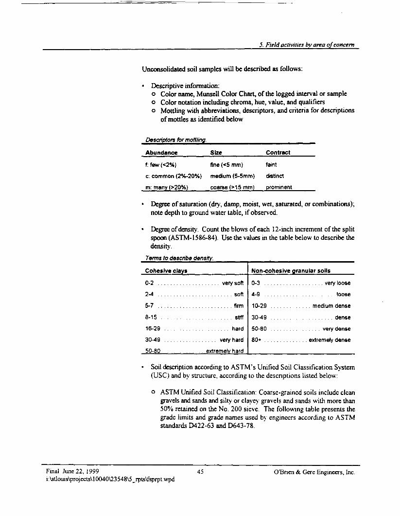
5. Field activities by area of concern
Unconsolidatcd soil samples will be described as follows:
• Descriptive information:o Color name, Munsell Color Chart, of the logged interval or sampleo Color notation including chroma, hue, value, and qualifierso Mottling with abbreviations, descriptors, and criteria for descriptions
of mottles as identified below
Descriptors for mottling.
Abundance
f: few (<2%)
c: common (2%-20%)
m: many (>20%)
Size
fine (<5 mm)
medium (5-5mm)
coarse (>1 5 mm)
Contract
faint
distinct
prominent
Degree of saturation (dry, damp, moist, wet, saturated, or combinations);note depth to ground water table, if observed.
Degree of density. Count the blows of each 12-inch increment of the splitspoon (ASTM-1586-84). Use the values in the table below to describe thedensity.
Terms to describe density._____
Cohesive clays
0-2 . . . . . . . . . . . . . . . . . . . . very soft
2 - 4 . . . . . . . . . . . . . . . . . . . . . . . soft5-7 . . . . . . . . . . . . . . . . . . . . . . . . firm
8-15 . . . . . . . . . . . . . . . . . . . . . . . stiff
16-29 . . . . . . . . . . . . . . . . . . . . . hard
30-49 . . . . . . . . . . . . . . . . . very hard
50-80 . . . . . . . . extremely hard
Non-cohesive granular soils
0-3 . . . . . . . . . . . . . . . . . . . very loose
4 -9 . . . . . . . . . . . . . . . . . . . . . . loose
10-29 . . . . . . . . . . . . . medium dense
30-49 . . . . . . . . . . . . . . . . . . . . dense
50-80 . . . . . . . . . . . . . . . . very dense
80+ . . . . . . . . . . . . . . extremely dense
Soil description according to ASTM's Unified Soil Classification System(USC) and by structure, according to the descriptions listed below:
o ASTM Unified Soil Classification: Coarse-grained soils include cleangravels and sands and silty or clayey gravels and sands with more than50% retained on the No. 200 sieve. The following table presents thegrade limits and grade names used by engineers according to ASTMstandards D422-63 and D643-78.
Final June 22, 1999i:\stlouis\projects\10040\23548V5_rpts\fsprpt.wpd
45 CCBnen & Gere Engineers, Inc.
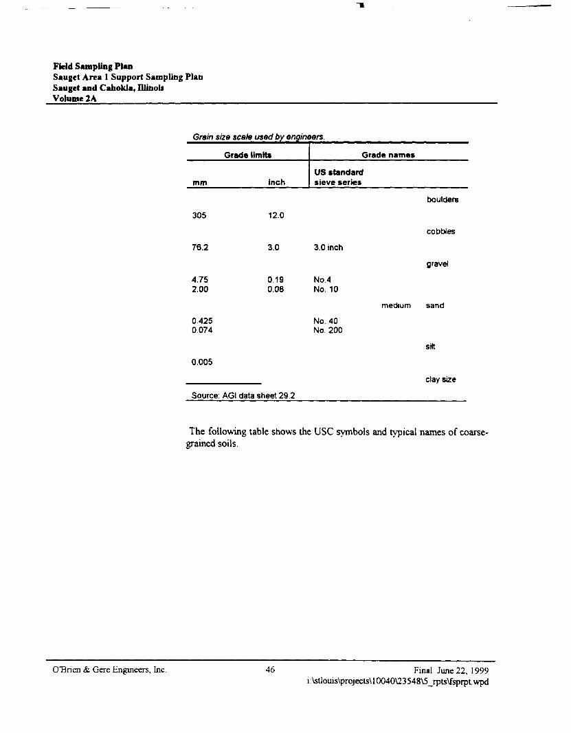
Field Sampling PlanSauget Area 1 Support Sampling PlanSauget and Cahokia, DlinouVolume 2A
Grain size scale used by engineers.
Grade limits
mm inch
Grade name*
US standardsieve series
305
76.2
12.0
3.0 3.0 inch
boulders
cobbles
gravel
4.75 0.192.00 0.06
0.4250.074
0.005
Source: AGI data sheet 29.2
No.4No. 10
No. 40No. 200
medium sand
silt
clay size
The following table shows the USC symbols and typical names of coarse-grained soils.
OBnen & Gere Engineers, Inc. 46 Final June 22, 1999i:\stlouis\projects\10040\23548\5_rpts\fsprpt.wpd
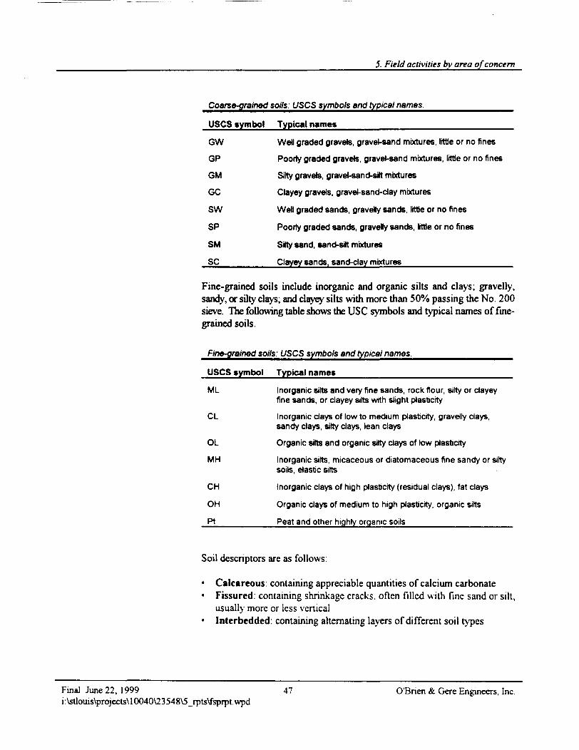
5. Field activities by area of concern
Coarse-grained soils: USCS symbols and typical names.
USCS symbol Typical names_______________________
GW Well graded gravels, gravel-sand mixtures, little or no fines
GP Poorly graded gravels, gravel-sand mixtures, little or no fines
GM Silty gravels, gravel-sand-silt mixtures
GC Clayey gravels, gravel-sand-day mixtures
SW Well graded sands, gravelly sands, little or no fines
SP Poorly graded sands, gravelly sands, little or no fines
SM Silty sand, sand-silt mixtures
SC________Clayey sands, sand-clay mixtures_______________
Fine-grained soils include inorganic and organic silts and clays; gravelly,sandy, or silty clays; and clayey silts with more than 50% passing the No. 200sieve. The following table shows the USC symbols and typical names of fine-grained soils.
Fine-grained soils: USCS symbols and typical names.
USCS symbol Typical names_________________________
ML Inorganic silts and very fine sands, rock flour, silty or clayeyfine sands, or clayey silts with slight plasticity
CL Inorganic days of low to medium plasticity, gravelly clays,sandy days, silty clays, lean clays
OL Organic silts and organic silty days of low plasticity
MH Inorganic silts, micaceous or diatomaceous fine sandy or siltysoils, elastic silts
CH Inorganic clays of high plasticity (residual clays), fat clays
OH Organic clays of medium to high plasticity, organic silts
Pt_________Peat and other highly organic soils_______________
Soil descriptors are as follows:
• Calcareous: containing appreciable quantities of calcium carbonate• Fissured, containing shrinkage cracks, often filled with fine sand or silt,
usually more or less vertical• Interbedded: containing alternating layers of different soil types
Final June 22, 1999 47 O'Bnen & Gere Engineers, Inci:\stlouis\projects\10040\23548\5_rpts\fsprpt.wpd
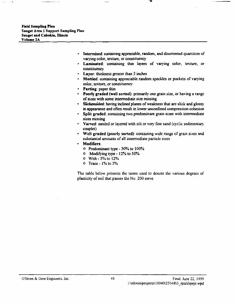
Field Sampling PlanSauget Area 1 Support Sampling PlanSauget and Cabokia, IllinoisVolume 2A
• Intermixed: containing appreciable, random, and disoriented quantities ofvarying color, texture, or constituency
• Laminated: containing thin layers of varying color, texture, orconstituency
• Layer: thickness greater than 3 inches• Mottled: containing appreciable random speckles or pockets of varying
color, texture, or constituency• Parting: paper thin• Poorly graded (well sorted): primarily one grain size, or having a range
of sizes with some intermediate size missing• Slickensided: having inclined planes of weakness that are slick and glossy
in appearance and often result in lower unconfined compression cohesion• Split graded: containing two predominant grain sizes with intermediate
sizes missing• Varved: sanded or layered with silt or very fine sand (cyclic sedimentary
couplet)• Well graded (poorly sorted): containing wide range of grain sizes and
substantial amounts of all intermediate particle sizes• Modifiers:
o Predominant type - 50% to 100%o Modifying type - 12% to 50%o With-5% to 12%o Trace - 1% to 5%
The table below presents the terms used to denote the various degrees ofplasticity of soil that passes the No. 200 sieve.
OBnen & Gere Engineers, Inc. 48 Final June 22, 1999i:\stlouis\projects\10040\23548\5_rpts\fsprpt.wpd
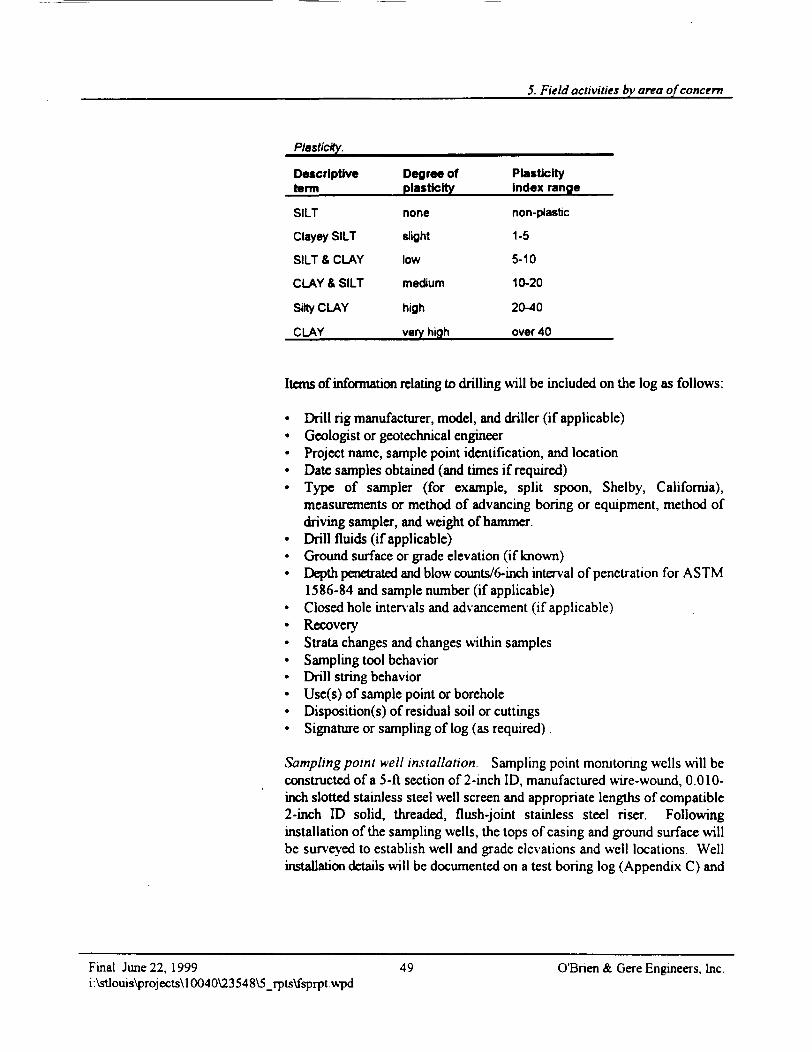
5. Field activities by area of concern
Plasticity.
Descriptiveterm
SILT
Clayey SILT
SILT & CLAY
CLAY & SILT
Silty CLAY
CLAY
Degree ofplasticity
none
slight
low
medium
high
very high
Plasticityindex range
non-plastic
1-5
5-10
10-20
20-40
over 40
Items of information relating to drilling will be included on the log as follows:
• Drill rig manufacturer, model, and driller (if applicable)• Geologist or geotechnical engineer• Project name, sample point identification, and location• Date samples obtained (and times if required)• Type of sampler (for example, split spoon, Shelby, California),
measurements or method of advancing boring or equipment, method ofdriving sampler, and weight of hammer.
• Drill fluids (if applicable)• Ground surface or grade elevation (if known)• Depth penetrated and blow counts/6-inch interval of penetration for ASTM
1586-84 and sample number (if applicable)• Closed hole intervals and advancement (if applicable)• Recovery• Strata changes and changes within samples• Sampling tool behavior• Drill string behavior• Use(s) of sample point or borehole• Disposition(s) of residual soil or cuttings• Signature or sampling of log (as required).
Sampling point well installation. Sampling point monitoring wells will beconstructed of a 5-ft section of 2-inch ID, manufactured wire-wound, 0.010-inch slotted stainless steel well screen and appropriate lengths of compatible2-inch ID solid, threaded, flush-joint stainless steel riser. Followinginstallation of the sampling wells, the tops of casing and ground surface willbe surveyed to establish well and grade elevations and well locations. Wellinstallation details will be documented on a test boring log (Appendix C) and
Final June 22, 1999 49 O'Bnen & Gere Engineers, Inc.i:\stlouis\projects\10040\23548\5_rpts\fsprpt.wpd
Fkld Sampling PlanSauget Area 1 Support Sampling PlanSauget and Cahokia, IllinoisVolume 2A
in the field notebook. The sampling point wells will generally be installedaccording to the typical well construction diagrams in Appendix D and asfollows:
• Well materials will be inspected for proper specifications and integrity.
• The well screen, bottom cap, plug, and riser will be certified clean from themanufacturer. If they are not, they will be cleaned with a high-pressuresteam cleaner.
• The total depth of the borehole will be measured referenced to existinggrade and recorded. The quantities and lengths of all materials placed inthe borehole will be measured and recorded. These materials include, butare not limited to: screen interval, blank casing or riser length, filter pack,bentonite seal, grout, and protective casing.
• The screen (with bottom cap) and riser assembly will be installed such thatits midpoint approximately intersects the ground water table in the shallowground water monitoring wells. The entire thickness of the intermediateaquifer will be screened. The well must be straight and vertical.Centralizers will be used as necessary to keep the monitoring well centeredin the borehole.
• The filter pack will consist of an appropriately graded, washed silica sand,the thirtieth percentile grain size value of which must be four to ten timesthe equivalent thirtieth percentile grain size value of the stratum beingmonitored. The filter pack material will have a uniformity coefficient lessthan or equal to 2.5. The volume of filter pack necessary to fill the annularspace will be computed and used to monitor the progress of installing thefilter pack. The filter pack will be emplaced in increments to preventbridging. If bridging occurs, the bridge will be broken before proceeding.The depth of the filter pack will be continuously checked with a weightedtape The filter pack will extend a minimum of 2 ft above the top of thewell screen.
• The augers or temporary casing will be withdrawn in no more than 5-ftincrements to limit borehole collapse during emplacement of the filterpack. The lowest point of the casing or auger will not be more than 2 fthigher than the top of the filter material
OBnen & Gere Engineers, Inc. 50 Final June 22, 1999i:\stlouis\projects\10040\23548\5_rpts\fsprpt.wpd
5. Field activities by area of concern
• A bentonite slurry seal will be tremied in place above the filter pack. Thebentonite slurry seal will extend a minimum of 2 ft and not more than 3 ftabove the top of the filter pack.
• A cement and bentonite grout mixture consisting of 5% bentonite byweight and Portland Type I cement will be tremied in place above the topof the bentonite slurry seal to 3 ft below existing grade. The grout mixturewill be installed from the top of the bentonite seal upward to reduce theopportunity for the development of void spaces in the emplaced grout. Thegrout mixture must be pH neutral so as not to modify the pH of the groundwater.
• A protective casing will be installed which extends from below the frostline to slightly above the top of the well casing. A weep hole will be drilledinto the protective casing so accumulated water can drain.
• The concrete to be used to complete surface installation will be acommercially available, premixed cement, sand, and gravel mixture (e.g.,Quickrete).
Equipment decontamination. Decontamination of drilling and soil samplecollection equipment will be performed prior to initiating drilling procedures,between boring locations, and at the completion of the drilling program priorto removal of equipment from the site. Drilling equipment and associatedtools, including augers, drill rods, wrenches, auger shoes, split spoon samplers,and other equipment, that comes into contact with generated soils will bedecontaminated by spray- washing with a high-pressure steam-cleaner. Priorto decontaminating the augers, as much soil as is practical will be removed andplaced into the drum(s) associated with that particular boring location. Adecontamination station will be set up by the drilling contractor such thatdecontamination fluids can be contained in drums. Decontamination solidswill be placed with drummed soil cuttings. The split spoon sampler will bedecontaminated with an Alconox soap wash, followed by a potable water rinsebetween sample collection at a particular location. The split spoon samplerwill be decontaminated utilizing the high pressure steam cleaner betweenboring locations.
Disposal of investigation-derived wastes. During the subsurfaceinvestigation, subsurface soils, ground water, decontamination water, andgeneral waste (plastic, paper, etc.) will be generated. Subsurface soils, groundwater (development and purge water), and equipment decontamination waterwill be temporarily contained in drums and transferred to waste containers.General waste will be contained in plastic bags and disposed in a general
Final June 22, 1999 51 O'Bnen & Gere Engineers, Inc.i:\stlouis\projects\10040\23548\5_rpts\fsprpt.wpd
Field Sampling PlanSauget Area 1 Support Sampling PlanSauget and Cahokia, IllinoisVolume 2A
refuse container. If appropriate, a portion of the waste cuttings may be usedfor treatability test samples.
5.3.4. DocumentationA field notebook will be kept for the soil boring installation. At a minimum,the field notebook will include project name and number, date and time,weather conditions, sampler's name, sample location, limiting field conditions,problems encountered, subcontractor personnel on-site, USEPA Region Vpersonnel on-site, and other project personnel on-site. Notation of USEPARegion V acceptance of boring locations will be included in the field notebook.
5.4. Magnetometer survey
5.4.1. Rationale/designMagnetometer surveys will be conducted at Sites G, H, I, L, and N to identifyanomalies indicative of drum disposal or buried tanks. To evaluate whetherthe anomalies are associated with buried drums or tanks, test trenches will bedug at anomalies that coincide with ground water isoconcentrations greaterthan 10,000 ppb as identified by the 1998 Ecology and Environment DataReport, soil vapor extraction (SVE)anomalies detected during the soil gassurvey, magnetic anomalies identified by the 1988 Ecology and Environmentgeophysical surveys, and areas of drum or tank disposal identified duringhistorical aerial photo analysis of fill area boundaries. Magnetometermeasurements will be made at locations determined by superimposing a 50 ftby 50 ft grid on the fill areas. Magnetometer measurement points will belocated in the field by using known points such as buildings, roads, or othercultural features or by using GPS.
OTBnen & Gere Engineers, Inc. 52 Final June 22, 1999i:\stlouis\projects\10040\23548\5_rpts\fsprpt.wpd
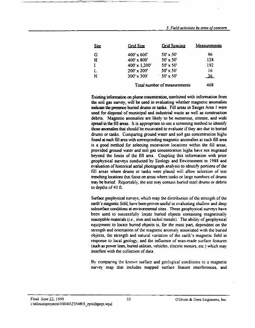
5. Field activities by area of concern
Site Grid Size Grid Spacing Measurements
G 400'x 600' 50'x50' 96H 400'x 800' 50'xSO1 128I 400'x 1,200' 50'x50' 192L 200'x 200' 50'x50' 16N 300'x 300' SO'xSO1 36
Total number of measurements 468
Existing information on plume concentration, combined with information fromthe soil gas survey, will be used in evaluating whether magnetic anomaliesindicate the presence buried drums or tanks. Fill areas in Sauget Area 1 wereused for disposal of municipal and industrial waste as well as constructiondebris. Magnetic anomalies are likely to be numerous, intense, and widespread in the fill areas. It is appropriate to use a screening method to identifythose anomalies that should be excavated to evaluate if they are due to burieddrums or tanks. Comparing ground water and soil gas concentration highsfound at each fill area with corresponding magnetic anomalies at each fill areais a good method for selecting excavation locations within the fill areas,provided ground water and soil gas concentration highs have not migratedbeyond the limits of the fill area. Coupling this information with priorgeophysical surveys conducted by Ecology and Environment in 1988 andevaluation of historical aerial photograph analysis to identify portions of thefill areas where drums or tanks were placed will allow selection of testtrenching locations that focus on areas where tanks or large numbers of drumsmay be buried. Reportably, the site may contain buried steel drums or debristo depths of 40 ft.
Surface geophysical surveys, which map the distribution of the strength of theearth's magnetic field, have been proven useful in evaluating shallow and deepsubsurface conditions at environmental sites. These geophysical surveys havebeen used to successfully locate buried objects containing magneticallysusceptible materials (i.e., iron and nickel metals). The ability of geophysicalequipment to locate buried objects is, for the most pan, dependent on thestrength and orientation of the magnetic anomaly associated with the buriedobjects, the strength and natural variation of the earth's magnetic field inresponse to local geology, and the influence of man-made surface features(such as power lines, buried utilities, vehicles, electric motors, etc.) which mayinterfere with the collection of data.
By comparing the known surface and geological conditions to a magneticsurvey map that includes mapped surface feature interferences, and
Final June 22, 1999 53 O'Bnen & Gere Engineers. Inc.i:\stlouis\projects\10040\23548\5_rpts\fsprpt.wpd
Field Sampling PlanSauget Area 1 Support Sampling PlanSauf et and Cahokia, IllinoisVolume 2A
understanding possible geologic background effects, it is possible to identifythe location of suspicious subsurface features which may represent buriedtanks or drum disposal areas.
Method. A geophysical survey of the site's magnetic field will be completedutilizing a total field magnetometer. The total field magnetometer measuresthe total strength of the site's magnetic field regardless of the orientation of themagnetic lines of force. The proposed field method involves the collection ofmagnetic data along pre-established profile lines. During the performance ofthe geophysical survey, data for the preparation of a field map will becollected. These data will include the total magnetic field strength at each datastation, the location of physical site conditions (i.e., streams, ditches, lowareas, etc.), and the location of potential surface interferences (i.e., vehicles,overhead power lines, etc.).
A correction for diurnal and micopulsation time variations is not necessarybecause the site and anticipated anomalies are relatively small in area (lessthan 1 sq mi), and subsurface anomalies from buried objects of interest shouldbe relatively large (greater than 100 gammas).
A map showing the distribution of magnetic field strength over the five siteswill be compiled and compared with the observed field conditions (includingthe location of known interfering objects such as vehicles, overhead powerlines, and surface debris). By comparison, those magnetic anomalies whichcannot be explained by observed site conditions will be presumed to be a resultof buried subsurface material (i.e., drums, tanks, metal uebris, etc.). The depthof detection for suspect objects (such as steel drums) may vary according toorientation, method of manufacture and condition, and numbers present. Steeldrums, such as those suspected to be present at this site, may be detected todepths of 40 ft.
Study area definition and measurement spacing. The area of the propertiesto be surveyed will be evaluated in the field. However, a general area for eachsurvey area has been delineated and provided on a site plan (Figure 1). Thestudy area consists of five site areas described above
Overall site dimensions for the area will be adjusted based upon the findingsof the source area boundary delineation activities discussed in section 5.1.
CCBnen & Gere Engineers, Inc 54 Final June 22, 1999i:\stlouis\projects\10040\23548\5_rpts\fsprpt. wpd
5. Field activities by area of concern
5.4.2. Field proceduresThe following field equipment and procedures will be employed during thisgeophysical investigation.
Equipment. A Geometries 858 Cesium or a Geometries 856AX Total FieldMagnetometer will be used to collect the field data. Field procedures andoperation of the instruments will be in accordance with the recommendedmanufacturer's field procedure and application manual.
Calibrated field survey equipment consisting of marked survey line, taperulers, highway danger cones, and marked wooden stakes will be utilized toestablish measurement locations.
Preliminary testing and early termination procedures. The magnetometerhas an internal startup test and check program which performs a diagnosticcheck of the battery and electronic circuitry. The unit will issue a warningstatement if all components do not perform within the designed specifications.The magnetometer will not operate if the internal system check is out ofcompliance.
Instrument calibration and quality control procedures. The magnetometerwill be calibrated to provide approximate value based on the establishedmagnetic intensity for the region. The assumed magnetic field intensity for thesite area is 51,000 gammas (based on the 1973 US Navy Map in: ApplicationsManual for Portable Magnetometers, Breiner, 1973). The calibrationprocedure is explained in the appropriate owner's operation manual and willvary between instrument models. The precise value for the intensity of theearth's magnetitic field at the site is not necessary to identify the location ofburied drums.
Following the calibration of the instrument, a field check of the magnetometerreadings will be conducted. Here, the instrument is held motionless and tenreadings are recorded. Variations in the recorded value of + or - 1 gamma isacceptable. Adjustment in the height of the magnetometer sensor may benecessary to reduce the interference from surface debris; however, for thepurpose of this investigation, a standard sensor height of 2 m will be assumed
A continuous quality control program will be maintained by visuallyinspecting the data as they are acquired. The data are displayed in a digitalformat and an electronic beep is used to signal if data collection problems haveresulted during the measurement. If a problem is detected, the measurementpoint will be recollected The survey will not be continued until the dataintegrity has been assured.
Final June 22, 1999 55 O'Bnen & Gere Engineers, Inc.i:\stlouis\projects\10040\23548\5_rpts\fsprpt.wpd
Field Sampling PlanSauget Area 1 Support Sampling PlanSauget and Cahokia, IllinoisVolume 2A
Field progress/interpretation reporting. Progression of the geophysicalsurvey will be documented in a field notebook. The beginning and ending timeof each profile will be noted, and a field map of each completed profile will bemaintained to field verify the progress of the survey.
Following the completion of the survey at each site, the magnetometer datawill be downloaded twice to a laptop computer. Later, the two databases willbe graphically compared to verify that the data download was complete andthat the fidelity of the data transferred was protected.
Measurement point/grid surveying. The established survey lines will bemarked in the field using a premarked survey line to maintain straight andprecise station locations. Profiles will be completed along a straight line withan unobstructed line of sight. The comers of each of the grided areas will bemarked with temporary corner stakes to permit the relocation of themeasurement points within each site.
Data processing. Following completion of the field phase of investigationand verification that magnetometer data have been successfully transferred tothe computer, the following data processing will be performed:
• A graphical review of data will be performed to compare the duplicatedatabases for completeness and fidelity.
• Cartesian coordinates corresponding to the map location of eachmeasurement point will be assigned to the appropriate magnetometerreading.
• A map display of these data will be produced showing the location of themeasurement points and the corresponding magnetometer reading. Thismap will be produced using AutoCAD Revision 14.
O"Bnen & Gere Engineers, Inc. 56 Final June 22, 1999i:\stlouis\projects\10040\23548\5_rpts\fsprpt.wpd
5. Field activities by area of concern
5.5. Buried drum and tank identification - test trenches
5.5.1. Rationale/designIf no excavation location criteria other than the presence of a magneticanomaly is used to evaluate whether an excavation is appropriate, disturbanceof a significant portion of each fill area is likely to result. Excessive trenchingcould result in unacceptable risks to the community, on-sitc workers, and theenvironment at sites that currently appear to be stable.
Test trenches to confirm the presence of buried drums or tanks will beconducted at Sites G, H, 1, L, and N. Site G is a fill area stabilized by USEPARegion V in an emergency response that solidified organic wastes, placed atemporary soil cover the site, and controlled site access by installation of afence. Recent inspection indicates the site is still stable. Site H is a grass fieldat the intersection of two major roads, Queeny Avenue and Falling SpringsRoad. It is across the street from the Cahokia Village Hall. Recent inspectionindicates the site is stable with a vegetative cover and no wastes exposed at thesurface. Commercial buildings and a self-storage facility are located on thesite. Site L is located in a vegetated field and appears stable. Site N is locatedat the rear of a former construction company site that is now occupied by whatappears to be a sign company, based on the large amount of sign installationand maintenance equipment parked in the parking along Falling Springs Road.The stability of Site N could not be assessed because it was not visible frompublicly accessible areas. Evidence of site clearing across the entire parcelwas readily discernible from Falling Springs Road.
Test trench locations will be identified using a combination of magneticanomalies, aerial photograph analysis, and soil gas and ground water data.Test trenches will be conducted to evaluate the presence of buried drums ortanks at the sites. One test trench will be conducted at the largest magneticanomaly found at each site that coincides with drum/tank disposal locationsidentified by historical aerial photograph analysis, an area of high VOCconcentration in soil gas, an area of high ground water concentration identifiedin the 1998 Ecology and Environment Sauget Area 1 Data Report, or majormagnetic anomalies report in the 1988 Ecology and Environment Report"Expanded Site Investigation, Dead Creek Project Sites at Cahokia/Sauget,Illinois". Care will be taken not to place major emphasis on the comparisonof historical ground water concentrations and magnetic anomalies due to theextent of historical industrial ground water pumping in the area Excavatedsoil and fill material will be returned to the test trench, with the exception ofany intact drums, which will be removed provided confined space entry is not
Final June 22, 1999 57 O'Bnen & Gere Engineers, Inc.i :\stlouis\prpjects\ 10040\23 548\5_rpts\fsprpt wpd
Field Sampling PlanSauget Area 1 Support Sampling PlanSauget and Caholda, DlinoiiVolume 2A
needed to retrieve a drum. Trenches will not be entered to recover drumsbecause of the danger inherent in such activities. Test trench locations will bedetermined using GPS and recorded for future reference in the event drumremoval is appropriate. Recovered drums will be overpacked and storedpending disposal.
Free product and contaminated soil resulting from rupture of drums duringremoval will be cleaned up by absorbing any liquid materials and placing theabsorbent, solid waste and contaminated soil in bulk containers at a controlled-access, fenced, investigation derived waste storage area to be constructed northof Judith Lane adjacent to Dead Creek. Overpacked drums will also bestored at this facility. Drum and waste storage may be indefinite if they containmaterials that can not be accepted by off-site disposal facilities, e.g. dioxin.Any waste excavated that identifies the source of material present in the fillarea will be noted in the field log and photographed.
Trenching to remove buried drums or tanks is an activity that should be done,if necessary, as part of a carefully planned removal action or when a remedyis implemented. Solutia is very concerned about the safety of workers, thecommunity, and the environment during test trenching and drum removalactivities. One release to the atmosphere, which sent five workers to thehospital, occurred during an investigation conducted in Creek Segment A.During World War II, the US government built and operated the ChemicalWarfare Plant on 15 acres located in Monsanto's W.G. Krummrich plant.Solutia does not know what chemicals were produced by this facility. It isquite likely that raw materials, waste materials, and finished product from theUS government's Chemical Warfare Service plant could be present in the fillareas located in Sauget Area 1. For this reason, Solutia believes intrusiveactivities at Sites G, H, and I to identify buried drums and tanks should be keptto an absolute minimum, if they are conducted at all. With the inherent dangerto workers, the public, and the environment associated with drum removalactivities, limited ground water downgradient migration of constituents at SitesG, H, and I and no downgradient ground water users, drum and tank removalduring site investigation does not seem appropriate. If large numbers of intactdrums are encountered and significant downgradient migration of constituentscould occur if they were left in place until a remedy could be implemented, acarefully planned and executed removal action to stabilize the situation couldbe appropriate.
O'Bnen & Gere Engineers, Inc. 58 Final June 22, 1999i:\stlouis\projects\10040\23548\5_rpts\fsprpt.wpd
5. Field activities by area of concern
5.5.2. Field proceduresAnomaly test trench locations will be selected in the field based upon theparameters outlined in section 5.5.1 above, and with the concurrence of theUSEPA Region V or its designee. To complete the anomaly test trenches, atrack-mounted or wheel-mounted hoe will be utilized. As the depth to the topof buried anomalies is not anticipated to be up to 40 ft below grade, a smallerpiece of equipment may be utilized for these anomaly test trenches comparedto the trenches completed under section 5.1 to delineate the fill area boundariesfor the sites. Trenching activities will be conducted in a manner to protectexisting utilities, structures, surface features, monitoring wells, and the generalsite environment. Additionally, trenching activities will follow OSHA rulesfor excavations. A PID, an explosimeter, and a RAM will be used on acontinuous basis to monitor the anomaly test trenches for hazardousconditions. The hoe operator will have a separate supplied-air system.Anomaly test trenches will be advanced until evidence as to the source of theanomaly is found or to a maximum depth of 40 ft, where possible. Shouldground water infiltration and/or poor soil stability result in the inability tocomplete a test trench to 40 ft, the trenching will be terminated at that location.No accommodations will be made to dewater test trenches or manage groundwater during excavation activities due to the need to minimize the generationof investigation-derived wastes. —-
— —
As the trenching proceeds, spoils from the test trenches will be placed onpolyethylene plastic having a minimum thickness of 6 mil. Provisions will bemade to allow free liquids in the spoils to drain back to the trench. Spoilsfrom each test trench will be segregated and returned to the excavation inreverse order of removal. Backfilling will be conducted in a manner tominimize ponding of water over the trench A silt fence will be installedaround the perimeter of the trench to minimize runoff of surface soils duringrain events. If intact drums are found during anomaly test trench completion,they will be removed, over-packed, and stored in an area to be designated inaccordance with the requirements of 29 CFR 1910.120(j) For planningpurposes, it is anticipated that up to ten over-packs will be necessary per siteand that one day of anomaly test trenching will occur at each of the five sites.A test trench at one location will be backfilled prior to the initiation of a testtrench at another location. After completion of site investigation activities, thesites will be revegetated with grass. The silt fence will be maintained untilrevegetation is completed. Handling of investigation-derived wastes fromthese activities is discussed in Chapter 9.
Final June 22, 1999i:\sUouis\projects\10040\23548\5_rpts\fsprpt.wpd
59 O'Bnen & Gere Engineers, Inc.
Field Sampling PlanSauget Area 1 Support Sampling PlanSauget and Cahokia, DlinouVolume 2A
5.5.3. DocumentationDuring anomaly trenching activities, a representative of O'Brien & Cere willcomplete a descriptive log for each anomaly test trench completed. At aminimum the following information will be included in the log:
• The date, time, weather conditions, equipment, and personnel on-site• The total depth, length, and width of the anomaly test trench• The depth and total thickness of distinct soil or lithologic units encountered• A description of any waste excavated, as well as the identification of the
source of the material, where possible• PID, explosimeter, and RAM readings.
Additionally, the location of the anomaly test trenches will be laid out on aplan of the site. Digital photographs will be taken of the anomaly testtrenches, the anomaly test trench walls, and any waste materials or drumsexcavated The number and location of each photograph will be identified onthe field log for each anomaly test trench.
5.6. Ground water sampling
Ground water samples will be collected in the alluvial aquifer and bedrock atthe fill areas, in the alluvial aquifer downgradient of the fill areas, and inshallow ground water and domestic wells adjacent to Dead Creek. Thepurpose of this sampling is to define current ground water quality conditionsat the source areas, to define the extent of migration away from the sourceareas, and to provide information for the human health risk assessment(construction/utility worker exposure, vapor intrusion into buildings, andresidential use of ground water from shallow wells for lawn and gardenwatering). The Human Health Risk Assessment Work Plan is in Volume IB
OBnen & Gere Engineers, Inc. 60 Final June 22, 1999i:\stlouis\projects\10040\23548\5_rpts\fsprpt.wpd
5. Field activities by area of concern
5.6.1. Degree of hazard and mobility of COCsSample number, sample coordinates, and organic and inorganic constituentsdetected in ground water during past investigations of Sauget Area 1 will becompiled into a GIS-compatible data base, along with data from the EE/CAand RI/FS SSP. Frequency of detection, and average, maximum, minimum,and 95% confidence interval concentrations will be compiled for each detectedconstituent. Constituent mobility and hazard will be assessed during thehuman health risk assessment (Volume IB Human Health Risk Assessmentof the SSP).
5.6.2. Recharge and discharge areasGround water conditions in the American Bottoms have been studiedextensively by the Illinois State Water Survey, Illinois State GeologicalSurvey, and the U.S. Geological Survey. Information from these studies willbe used to define recharge and discharge areas.
Experience at Site R and information from published reports on the AmericanBottoms aquifer indicate that ground water flow patterns in the study area areprimarily controlled by the Mississippi River and, to a lesser degree, by DeadCreek. Both drainages run north/south, and ground water will flow towardthem in an east/west direction. For ground water to flow from Sites G, H, I,and N to residences located south of these sites, a strong, local perturbation ofthe flow system would be needed, for example a high capacity pumping well.Plumes associated with Sites G, H, I, and L, as mapped by Ecology andEnvironment in 1998 (Appendix A of the SSP), do not indicate distortion ofthe plumes toward the residences on Walnut Street and Judith Lane.Intermittent pumping of domestic wells for gardening or lawn watering isunlikely to stress the aquifer enough to cause COCs to migrate 500 ft crossgradient. Evaluation of historical data, as described in section 5.6.3, willdetermine if high capacity industrial pumping occurred southwest of Site H.
To address USEPA Region V concern of a southwesterly flow direction fromthe source areas to the residential areas south of Judith Lane and west of DeadCreek, ground water samples will be collected at three locations on a transectrunning from Site G to Judith Lane
5.63. Regional and local flow direction and qualityGround water conditions in the American Bottoms have been studiedextensively by the Illinois State Water Survey, Illinois State Geological Survey
Final June 22, 1999 61 O'Bnen & Cere Engineers, Inc.i:\sUoms\projects\l(mO\23548\5_iT3ts\fsprpt.wpd
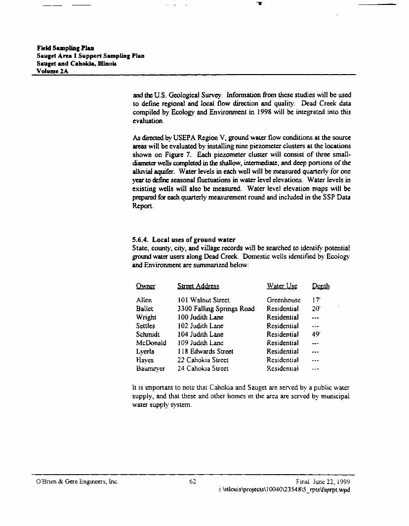
Field Sampling PlanSauget Area 1 Support Sampling PlanSauget and Cahokia, Dlinoi*Volume 2A
and the U.S. Geological Survey. Information from these studies will be usedto define regional and local flow direction and quality. Dead Creek datacompiled by Ecology and Environment in 1998 will be integrated into thisevaluation.
As directed by USEPA Region V, ground water flow conditions at the sourceareas will be evaluated by installing nine piezometer clusters at the locationsshown on Figure 7. Each piezometer cluster will consist of three small-diameter wells completed in the shallow, intermediate, and deep portions of thealluvial aquifer. Water levels in each well will be measured quarterly for oneyear to define seasonal fluctuations in water level elevations. Water levels inexisting wells will also be measured. Water level elevation maps will beprepared for each quarterly measurement round and included in the SSP DataReport.
5.6.4. Local uses of ground waterState, county, city, and village records will be searched to identify potentialground water users along Dead Creek. Domestic wells identified by Ecologyand Environment are summarized below:
Owner Street Address
Alien 101 Walnut StreetBallet 3300 Falling Springs RoadWright 100 Judith LaneSettles 102 Judith LaneSchmidt 104 Judith LaneMcDonald 109 Judith LaneLyerla 118 Edwards StreetHaves 22 Cahokia StreetBaumever 24 Cahokia Street
Water Use Depth
GreenhouseResidentialResidentialResidentialResidentialResidentialResidentialResidentialResidential
17'20'
49'
It is important to note that Cahokia and Sauget are served by a public watersupply, and that these and other homes in the area are served by municipalwater supply system.
O'Bnen & Gere Engineers, Inc. 62 Final June 22, 1999i:\stlouis\projects\10040\23548\5_rpts\fsprpt.wpd
5. Field activities by area of concern
5.63. Horizontal and vertical distribution of COCsEcology and Environment (1998) defined the areal extent of VOCs andSVOCs in shallow ground water at Sites G, H, I, and L. These plumes havemigrated several hundred feet downgradient from disposal sites that were usedfrom the 1930s to the 1970s. Plume shape indicates VOC and SVOCmigration toward the Mississippi River, which is the discharge point for theAmerican Bottoms aquifer. Ecology and Environment did not collectinformation on COC distribution in the intermediate and deep portions of theaquifer.
Aquifer saturated thickness in the study area is on the order of 80 to 100 ft,perhaps more. A vertical ground water sampling interval of 20 ft would resultin four to five ground water samples per sampling station. A vertical samplinginterval of 5 ft would result in sixteen to twenty samples per sampling station.Since the fill areas are 30 to more than 50 years old, the aquifer is thick, highlypermeable, and homogeneous, and experience with similar hydrogeologicconditions indicates that leachate migration from these areas should produceplumes with a vertical dimension of more than 5 ft. Under these conditions,plumes are likely to have a vertical dimension of at least 20 ft thick, if notmore. For this reason, a vertical sampling interval of 20 ft is consideredappropriate. However, in order to address USEPA Region V concerns aboutadequate characterization of the plumes, vertical ground water samples will becollected every 10 ft.
5.7. Fill areas ground water sampling
5.7.1. Rationale/designAs directed by USEPA Region V in its March 19,1999 comments on the SSP,ground water concentrations at the source areas will be evaluated by samplingexisting Ecology and Environment wells (Appendix B of the SSP) EE-01, EE-02, EE-03, EE-04, EE-05, EE-12, EE-13, EE-14, EE-15, EE-20, EEG-101,EEG-102, EEG-103, EEG-104, EEG-105, EEG-106, EEG-107, EEG-108,EEG-109, EEG-110, EEG-111, and EEG-112. Each well will be located,checked for integrity of surface seals, checked for non-aqueous-phase liquid(NAPL), plumbed for depth and matched against construction records,redeveloped to remove accumulated fine-grained materials and promoteground water entry into the well and sampled to provide data on currentground water conditions at the source areas. If some or all of these wells no
Final June 22, 1999 63 O'Bnen & Gere Engineers, Inci:\stlouis\projects\10040\23548\5_rp ts\fsprpt.wpd
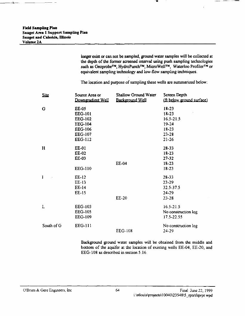
Field Sampling PlanSauget Area 1 Support Sampling PlanSauget and Cahokia, fflinouVolume 2A
longer exist or can not be sampled, ground water samples will be collected atthe depth of the former screened interval using push sampling technologiessuch as Geoprobe™, HydroPunch™, MicroWell™, Waterloo Profiler™ orequivalent sampling technology and low-flow sampling techniques.
The location and purpose of sampling these wells are summarized below:
Site
G
H
South of G
Source Area orDowngradient Well
EE-05EEG-101EEG-102EEG-104EEG-106EEG-107EEG-112
EE-01EE-02EE-03
EEG-110
EE-12EE-13EE-14EE-15
EEC-103EEG-105EEG-109
EEG-111
Shallow Ground WaterBackground Well
EE-04
EE-20
EEG-108
Screen Depth(ft below ground surface)
18-2318-2316.5-21.519-2418-2323-2821-26
28-3318-2327-3218-2318-23
28-3323-2932.5-37.524-2923-28
16.5-21.5No construction log17.5-22.55
No construction log24-29
Background ground water samples will be obtained from the middle andbottom of the aquifer at the location of existing wells EE-04, EE-20, andEEG-108 as described in section 5.16.
OTBnen & Gere Engineers, Inc. 64 Final June 22, 1999i:\stlouis\projects\10040\23548\5_rpts\fsprpt.wpd
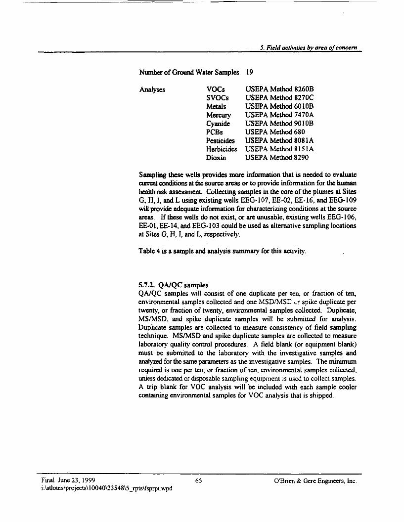
5. Field activities by area of concern
Number of Ground Water Samples 19
Analyses VOCs USEPA Method 8260BSVOCs USEPA Method 8270CMetals USEPA Method 6010BMercury USEPA Method 7470ACyanide USEPA Method 901 OBPCBs USEPA Method 680Pesticides USEPA Method 8081AHerbicides USEPA Method 8151ADioxin USEPA Method 8290
Sampling these wells provides more information that is needed to evaluatecurrent conditions at the source areas or to provide information for the humanhealth risk assessment Collecting samples in the core of the plumes at SitesG, H, I, and L using existing wells EEG-107, EE-02, EE-16, and EEG-109will provide adequate information for characterizing conditions at the sourceareas. If these wells do not exist, or are unusable, existing wells EEG-106,EE-01, EE-14, and EEG-103 could be used as alternative sampling locationsat Sites G, H, I, and L, respectively.
Table 4 is a sample and analysis summary for this activity.
5.7.2. QA/QC samplesQA/QC samples will consist of one duplicate per ten, or fraction of ten,environmental samples collected and one MSD/MSC cr spike duplicate pertwenty, or fraction of twenty, environmental samples collected. Duplicate,MS/MSD, and spike duplicate samples will be submitted for analysis.Duplicate samples are collected to measure consistency of field samplingtechnique. MS/MSD and spike duplicate samples are collected to measurelaboratory quality control procedures. A field blank (or equipment blank)must be submitted to the laboratory with the investigative samples andanalyzed for the same parameters as the investigative samples. The minimumrequired is one per ten, or fraction of ten, environmental samples collected,unless dedicated or disposable sampling equipment is used to collect samples.A trip blank for VOC analysis will be included with each sample coolercontaining environmental samples for VOC analysis that is shipped.
Final June 23, 1999 65 O'Bnen & Gere Engineers, Inc.i:\stlouis\projects\10040\23548\5_rpts\fsprpt.wpd
Field Sampling PlanSauget Area 1 Support Sampling PlanSauget and Cahokia, IllinoisVolume 2A
5.7.3. Field proceduresGround water monitoring well redevelopment (if required). The objectiveof ground water monitoring well redevelopment is to clear the well ofaccumulated sediments, when 10% or more of the well screen has beenoccluded by sediment, so that representative ground water samples may becollected. The accumulated sediments need to be re-suspended in the watercolumn in order to be removed. A variety of techniques can be used to re-suspend the sediments. Some of the common methods that can be used to re-suspend sediments include using a surge block, injection of air into the watercolumn of the well, or using a bailer. Once the sediment is re-suspended, thewater and sediment can then be removed from the well using a submersiblepump, an air bladder pump, or a bailer. Redevelopment will be considered tobe complete when the fine-grained materials have been removed.
For the existing ground water monitoring wells to be sampled for this project,the preferred method for redevelopment will be to use a surge block to re-suspend the sediments, and a submersible pump to remove the water andsuspended sediments. However, if this method is ineffective, a combinationof one or more of the methods indicated above will be used. The followingprocedures will be used when redeveloping an existing well.
• Place a clean, plastic drop cloth on the ground around the well to beredeveloped.
• Unlock the protective well cover and remove the well cap
• Check the well for NAPL using an interface probe, as outlined in the waterlevel measurement section below.
• Measure the depth to ground water and/or NAPL to the nearest hundredthof afoot.
• Measure the total depth of the well to the nearest hundredth of a foot. Notewhether the bottom of the well feels hard or soft.
• Compare the total measured depth of the well to the record installed depthof the well, if available.
O'Bncn &. Gere Engineers, Inc. 66 l-'mal July 29, 1999i \stlouis\projecls\ 10040\23548\5_rpts\fsprpt.wpd
5. Field activities by area of concern
• If the comparison shows greater than 10% occlusion of the well screen,proceed with redevelopment. For wells that have no recorded installeddepth and have a soft bottom, assume redevelopment will be required.
• Attach the decontaminated surge block to the appropriate lengths of polesection and push the surge block to the bottom of the well.
• Pull and push the surge block up and down to agitate the water andsuspend the sediments in the well.
• Once sufficient re-suspension has occurred, pull the surge block out of thewell.
• Attach an appropriate length of polyethylene tubing to a submersiblepump, and lower the pump to near the bottom of the well, out of sedimentthat may be remaining in the bottom of the well.
• Place the discharge end of the tubing such that purged water will becollected in a 5 5-gal drum.
• Turn on the pump and adjust the flow rate to pump at a sufficiently highrate to allow the sediments to be removed without causing the pump toclog.
• Continue pumping until relatively sediment-free water is obtained.
• Remove the pump and allow the well to recover for half an hour Re-measure the total well depth. If the measured depth indicates 10% or moreocclusion, repeat steps 8 through 14. If the measured depth indicates lessthan 10% well screen occlusion, disconnect the tubing from the pump andplace into the appropriate waste container. Dismantle the surge block andpole connectors for decontamination. Close and lock the protective casing.And, pick up and appropriately dispose of plastic sheeting and otherdisposables into the appropriate waste container. Close and properly labelthe 55-gal drum(s).
• Decontaminate the pump, wiring, and surge block system using the steamcleaner.
• Note in the field log book the approximate number of gallons of waterremoved during redevelopment of each well
Final July 29, 1999 67 O'Bnen & Gere Engineers, Inc.i:\stlouis\projects\10040\23548\5_rpts\fsprpt.wpd
Field Sampling PlanSauget Area 1 Support Sampling PlanSauget and Caholda, DlioouVolume 2A
Pre-sampling procedures. As part of a sampling event, the following stepswill initially be taken by personnel responsible for sampling:
• Obtain appropriate containers for sample collection. Containers will beprovided by the laboratory performing the analyses.
• Examine sampler, containers, and preservatives; contact laboratoryimmediately if problems are found.
• Confirm sample delivery time and method of sample shipment with thelaboratory.
• Assemble and inspect field equipment to be used for sample collection;verify that equipment is clean and in proper working order.
• Calibrate field instruments and/or meters to manufacturers' specifications.Conductivity, pH, and turbidity meters will be calibrated to knowncalibration standard solutions. Re-check calibration prior to the start ofeach day and after four hours of use. Calibration activities will be recordedon the ground water sampling log (Appendix E) and in the field notebook.
• Perform NAPL interface probe function test in accordance with section6.1.11 of the Project QAPP.
• Establish well location and well identification.
• Obtain necessary keys for wells or gates.
• As feasible, begin sampling procedures at monitoring wells that are leastimpacted and proceed to those that historically have been impacted. Areview of previous analytical data will be required prior to sampling.
• Examine each well for damage, tampenng, erosion around the well casing,etc., and note on respective field log sheet
• Place clean plastic sheeting around well to provide a barrier between thesurrounding ground surface and sampling equipment used.
• Put on a new pair of disposable gloves.
O'Bnen & Gere Engineers, Inc. 68 Final Ju ly 29, 1999i:\sllouis\projects\10040\23548\5_rpts\fsprpl.wpd
5. Field activities by area of concern
• Open well cap and make a visual check down the casing and note thecondition of the well casing and whether a permanent ground water levelreference point has been established on the casing. Note on respective fieldlog sheet.
• Perform ambient air monitoring for hazardous conditions on a continuousbasis following opening of the well using a PID and an explosimeter.Record readings in the field notebook.
Water level measurements. Prior to initiating ground water sampling, waterelevations will be measured in each of the wells on-site. Ground water levelmeasurements will be collected as follows:
• A pre-cleaned, electric water level or NAPL interface probe will be used tomeasure the depth to water from the top-of-casing reference point and/orto check for NAPLs in the water column, where applicable. Record thedepth of water and/or NAPLs, as applicable. This procedure will also beused to measure the depth of the well. Measurements will be made to thenearest 0.01 ft.
• After obtaining the water level, the volume of water within the well will becalculated.
• Decontaminate the water level and NAPL interface probe used in the wellby thoroughly scrubbing with an Alconox® and potable water wash. Rinsewith potable water, and then rinse twice with distilled water
Record keeping. Pnor to initiating the well purging process, the followinginformation will be recorded in a field notebook and on the ground watersampling logs (Appendix E):
• Well number• Day, date, and time• Weather conditions• Condition of the well and the surrounding area• Sampling team members• Instrument calibration information (before and after)• Water level prior to purging• Depth to the bottom of the well• Volume of water to be purged• Physical properties of evacuated water: color, odor, turbidity, presence of
non-aqueous phase liquids
Final July 29, 1999 69 O'Bnen & Gere Engineers, Inci:\stlouis\projects\10040\23548\5_rpts\fsprpt.wpd
Field Sampling PlanSauget Area 1 Support Sampling PlanSauget and Cahokia, IllinoisVolume 2A
• Deviations from planned sampling methodology• Ambient air monitoring readings.
Well purging. Prior to sampling, the wells will be purged to remove thestanding water column from the well casing. A well volume of water iscalculated using the following formula: V = 71^(7.48) where
V = Standing water volume in gallons to be purged
r2 = inside radius of well in feet, squared
h = Linear feet of standing water in the casing.
One well volume will be calculated so field personnel know when to performfield measurements. Such measurements are performed after the removal ofeach well volume.
In ground water systems, naturally occurring metals tend to adsorb to thesurfaces of solids. The level of adsorbance depends on the pH of the soil andwater. The concentration of metals in dissolved form, therefore, is limited bythis adsorption and by the metals' low solubility. Sediment in water is likelyto have metal ions adsorbed to its particles, which analytical methods may notbe able to differentiate from metal ions dissolved in the water. Ground watersamples that contain sediment, therefore, may yield analytical results that donot represent the concentration of metals in the ground water itself.
Moreover, the transport of sediment is generally not due to the natural flow ofground water, but is induced by the sampling. Samples that are collected tobe analyzed for metals should exhibit low turbidity, and they are generallyfiltered, therefore, to remove sediment/When possible, low turbidity samplesshould be obtained without filtering. Therefore, a low-flow peristaltic pumpwill be used at an appropriate flow rate of 100 ml/min for purging and tocollect ground water samples. Should ground water depths exceed the suctionhead limitations of a peristaltic pump, a micro-bailer will be utilized forsample collection. A turbidity meter will-be used to monitor turbidity duringsampling. Following the extraction of each well volume, turbidity will bemonitored in the field. Additionally, pH, conductivity, and temperature willbe measured and recorded after each well volume removed. Samples will becollected when turbidity levels are below 5 nephelomctnc turbidity units
OT3nen & Gere Engineers, Inc. -70 Final July 29, 1999i:\stlouis\projects\l 0040\23548\5_rpts\fsprpt.wpd
5. Field activities by area of concern
(NTU). Should a turbidity level of 5 NTU be unachievable after 2 hours ofpurging, the samples will be collected and the turbidity recorded.
The procedures for well purging are described as follows:
• Prepare the pump for operation. Follow the manufacturer's directions.
• Lower the pump to the screened zone of the well.
• Pump the ground water into a graduated pail. Continue pumping until theturbidity reading is at or below 5 NTU or the well is pumped dry. Lowerthe pump's intake as necessary.
• If the well is pumped dry, allow sufficient time for the well to recoverbefore proceeding. Record this information on the ground water samplinglog.
• In addition to the turbidity readings, in wells which exhibit sufficientrecharge, also collect pH, conductivity, and temperature measurements.Three consecutive measurements should be within the following criteria:
o ±0.25 units for pHo ±10% for specific conductivityo ±1 C° for temperature.
Record this information on the ground water sampling log.
• Discharge the water removed during purging or possible decontaminationprocedures into 55-gal drums for disposal.
Sampling procedure. Each well will be sampled according to the followingprocedures:
• Remove the sample containers from their transport containers, and preparethe bottles for receiving samples. Inspect labels for proper sampleidentification. Sample containers will be kept cool with their caps on untilthey are ready to receive samples.
• The pump will be situated within the screened interval of the well so as totake into account past sampling activities and the fact that domestic wellscreens have been reported from 15 to 25 ft below ground surface Shouldthe water level in the well drop dunng pumping, the pump intake will beadjusted to maintain flow
Final July 29, 1999 71 O'Bnen & Gere Engineers, Inci:\stlouis\projects\10040\23548\5_rpts\fsprpt.wpd
Fkld Sampling PlanSauget Area 1 Support Sampling PlanSauget and Cahokia, IllinoisVolume 2A
• Fill sample containers for VOC samples prior to filling other samplecontainers.
• Fill remaining sample containers.
• If the sample containers cannot be filled quickly, keep sample containerscool with the cap on until filled. Sample containers will be preserved asdescribed in the QAPP.
• Return each sample container to its proper transport container. Preservesamples by reducing the temperature within the containers toapproximately 4° Celsius using ice. Samples must not be allowed tofreeze.
• Begin the chain-of-custody record.
• Record the physical appearance of the ground water observed duringsampling on the ground water sampling log or in the field notebook.
• Replace the well cap and lock the well protection assembly before leavingthe well location.
Sampling equipment decontamination.• Brush-wash reusable sampling equipment in a bucket or tub using a
trisodium phosphate (TSP), or other commercial detergent, solution (2 Ibof TSP per 10 gal of clean water). Completely brush the entire exteriorsurface of the article undergoing decontamination. Wash interior wettedsurfaces as required. Rinse the item with copious quantities of potablewater, followed by a distilled water nnse.
• Rinse reusable sampling equipment used to collect environmental mediafor metals analysis in a dilute nitnc acid solution, followed by a distilledwater rinse.
• Air-dry sampling equipment on a clean, non-plastic surface in a wellventilated, uncontammated environment If the sampling device is not tobe used immediately, wrap it in aluminum foil and place it in a plastic bagor storage container.
O'Bnen & Gere Engineers, Inc. Final July 29, 1999i:\stlouis\projects\10040\23548V5_rpts\fsprpt.wpd
5. Field activities by area of concern
• Contain rinse waters in a plastic tub with a lid. Empty the contents of thistub daily into a 55-gal drum located at the investigation-derived wastestorage area.
• Sample tubing will be disposed after each use, and new tubing will be usedfor each location.
Sample control and chain-of-custody.• For proper identification in the field and proper tracking in the laboratory,
samples will be labeled in a clear and consistent fashion, as outlined insection 6.1.2.
• Sample labels will be waterproof or sample containers will be sealed inplastic bags.
• Field personnel will maintain a sampling log sheet.
• The sampling log sheets will contain sufficient information to allowreconstruction of the sample collection and handling procedures at a latertime.
• Each ground water monitoring well will have a corresponding sample logsheet which includes:
o Sample identification numbero Well location and numbero Date and timeo Sampler's nameo Sample type (composite or grab)o Analysis for which sample was collectedo Field parameters, including pH, temperature, and conductivityo Method of preservationo Additional comments as necessary.
• Each sample will have a corresponding entry on a chain-of-custody record.The record will include the items listed in section 6.1.3.
Following completion of the chain-of-custody record, the samples will bepackaged for transport to the laboratory. A completed chain-of-custodydocument will be provided for each shipping container. The field sampler willmake a copy of the chain-of-custody document to keep with the field notebook,and include the original chain-of-custody document in an air-tight plastic bag
Final July 29, 1999 73 O'Bnen & Gere Engineers, Inc.i:\stlouis\projects\10040\23548\5_rpts\fsprptvvpd
Field Sampling PlanSaugct Area 1 Support Sampling PlanSauget and Cahokia, DlinoisVolume 2A
in the sample cooler with the associated samples. Sample packaging andshipping procedures are described in Chapter 8.
Purge water. Purge water generated from ground water sampling activitieswill be contained in 55-gal drums and transported to the liquid waste disposalcontainer.
Disposal of investigation-derived wastes. During the subsurfaceinvestigation, subsurface soils, ground water, decontamination water, andgeneral waste (plastic, paper, etc.) will be generated. Subsurface soils, groundwater (development and purge water), and equipment decontamination waterwill be temporarily contained in drums and transferred to waste containers.General waste will be contained in plastic bags and disposed in a generalrefuse container.
5.8. Alluvial aquifer ground water sampling
5.8.1. Rationale/designAs directed by USEPA Region V. one alluvial aquifer saturated-thicknesssampling station will be located at the ground water concentration high at SiteH and, one alluvial aquifer saturated-thickness sampling station will be locatedat the ground water concentration high at Site I (Figure 7). If available recordsor aenal photographs indicate the location of dredge spoil from Creek SegmentA, the Site I alluvial aquifer saturated thickness sampling station will beplaced at the location of this spoil instead of at the ground water concentrationhigh, as directed by the USAGE. Ground water samples will be collected atthese locations in order to evaluate the vertical extent of organic and inorganicconstituents migrating away from Sites H and I
Telescoping surface casing will be installed to depths of 5 ft and 20 ft belowthe fill material in order to minimize carry-down of site-related constituentsduring ground water sample collection. This casing will be grouted from thebottom up after completion of sampling.
O'Bnen & Gcre Engineers, Inc. 74 Final July 29, 1999i:\stlouis\projecLs\10040\23548\5_rpts\fsprpt.wpd
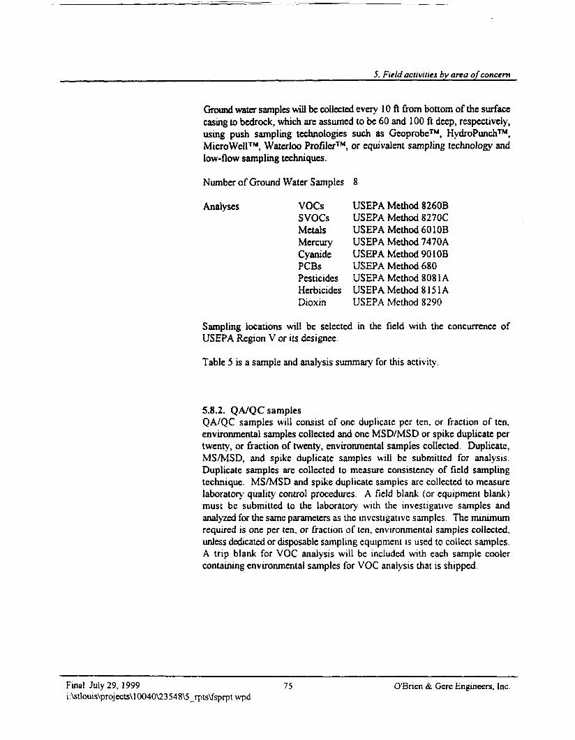
5. Field activities by area of concern
Ground water samples will be collected every 10 ft from bottom of the surfacecasing to bedrock, which are assumed to be 60 and 100 ft deep, respectively,using push sampling technologies such as Geoprobe™, HydroPunch™,MicroWell™, Waterloo Profiler™, or equivalent sampling technology andlow-flow sampling techniques.
Number of Ground Water Samples 8
Analyses VOCs USEPA Method 8260BSVOCs USEPA Method 8270CMetals USEPA Method 601 OBMercury USEPA Method 7470ACyanide USEPA Method 901 OBPCBs USEPA Method 680Pesticides USEPA Method 8081AHerbicides USEPA Method 8151ADioxin USEPA Method 8290
Sampling locations will be selected in the field with the concurrence ofUSEPA Region V or its designee.
Table 5 is a sample and analysis summary for this activity.
5.8.2. QA/QC samplesQA/QC samples will consist of one duplicate per ten, or fraction of ten,environmental samples collected and one MSD/MSD or spike duplicate pertwenty, or fraction of twenty, environmental samples collected. Duplicate,MS/MSD, and spike duplicate samples will be submitted for analysis.Duplicate samples are collected to measure consistency of field samplingtechnique. MS/MSD and spike duplicate samples arc collected to measurelaboratory quality control procedures. A field blank (or equipment blank)must be submitted to the laboratory with the investigative samples andanalyzed for the same parameters as the investigative samples. The minimumrequired is one per ten, or fraction of ten, environmental samples collected,unless dedicated or disposable sampling equipment is used to collect samples.A trip blank for VOC analysis will be included with each sample coolercontaining environmental samples for VOC analysis that is shipped.
Final July 29, 1999 75 O'Brien & Gere Engineers, Inc.i:\stlouis\projects\10040\23548\5_rpts\fsprpt\vpd
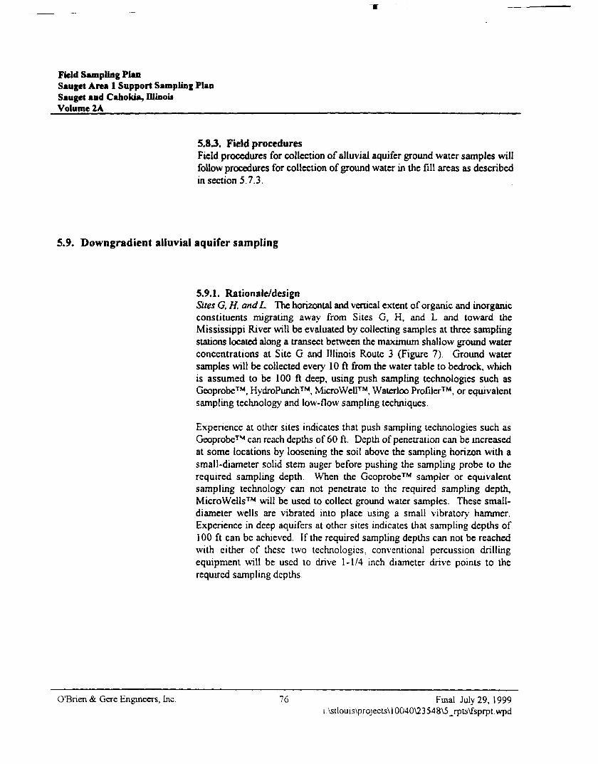
Field Sampling PlanSauget Area 1 Support Sampling PlanSauget and Cahokia, DlinoisVolume 2A
5.8 J. Field proceduresField procedures for collection of alluvial aquifer ground water samples willfollow procedures for collection of ground water in the fill areas as describedin section 5.7.3.
5.9. Downgradient alluvial aquifer sampling
5.9.1. Rationale/designSites G, H, andL The horizontal and vertical extent of organic and inorganicconstituents migrating away from Sites G, H, and L and toward theMississippi River will be evaluated by collecting samples at three samplingstations located along a transect between the maximum shallow ground waterconcentrations at Site G and Illinois Route 3 (Figure 7). Ground watersamples will be collected every 10 ft from the water table to bedrock, whichis assumed to be 100 ft deep, using push sampling technologies such asGeoprobe™, HydroPunch™, MicroWell™, Waterloo Profiler™, or equivalentsampling technology and low-flow sampling techniques.
Experience at other sites indicates that push sampling technologies such asGeoprobe™ can reach depths of 60 ft. Depth of penetration can be increasedat some locations by loosening the soil above the sampling horizon with asmall-diameter solid stem auger before pushing the sampling probe to therequired sampling depth. When the Geoprobe™ sampler or equivalentsampling technology can not penetrate to the required sampling depth,MicroWells™ will be used to collect ground water samples. These small-diameter wells are vibrated into place using a small vibratory hammer.Experience in deep aquifers at other sites indicates that sampling depths of100 ft can be achieved. If the required sampling depths can not be reachedwith cither of these two technologies, conventional percussion drillingequipment will be used to drive 1-1/4 inch diameter drive points to therequired sampling depths
O'Bnen & Gere Engineers, Inc. 76 Final July 29, 1999i:\stlouts\projectsU0040\23548V5_rpts\fsprpt.wpd
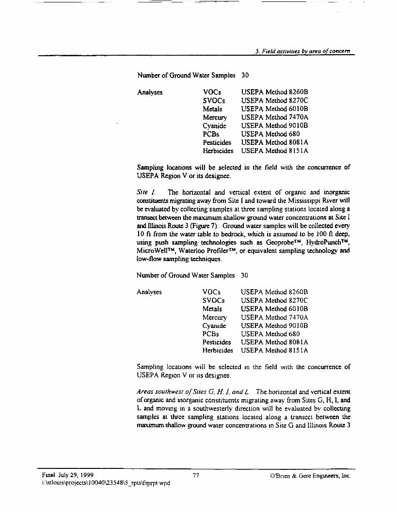
5. Field activities by area of concern
Number of Ground Water Samples 3 0
Analyses VOCs USEPA Method 8260BSVOCs USEPA Method 8270CMetals USEPA Method 6010BMercury USEPA Method 7470ACyanide USEPA Method 901 OBPCBs USEPA Method 680Pesticides USEPA Method 8081AHerbicides USEPA Method 8151A
Sampling locations will be selected in the field with the concurrence ofUSEPA Region V or its designee.
Site I. The horizontal and vertical extent of organic and inorganicconstituents migrating away from Site I and toward the Mississippi River willbe evaluated by collecting samples at three sampling stations located along atransect between the maximum shallow ground water concentrations at Site Iand Illinois Route 3 (Figure 7). Ground water samples will be collected every10 ft from the water table to bedrock, which is assumed to be 100 ft deep,using push sampling technologies such as Geoprobe™, HydroPunch™,MicroWell™, Waterloo Profiler™, or equivalent sampling technology andlow-flow sampling techniques.
Number of Ground Water Samples 30
Analyses VOCs USEPA Method 8260BSVOCs USEPA Method 8270CMetals USEPA Method 601 OBMercury USEPA Method 7470ACyanide USEPA Method 901 OBPCBs USEPA Method 680Pesticides USEPA Method 8081AHerbicides USEPA Method 8151A
Sampling locations will be selected in the field with the concurrence ofUSEPA Region V or its designee.
Areas southwest of Sites G, H, 1, and L The horizontal and vertical extentof organic and inorganic constituents migrating away from Sites G, H, I, andL and moving in a southwesterly direction will be evaluated by collectingsamples at three sampling stations located along a transect between themaximum shallow ground water concentrations in Site G and Illinois Route 3
Final July 29, 1999i:\stlouis\projects\10040\23548\5_rpts\fsprpt.wpd
77 O'Bnen & Gerc Engineers, Inc.
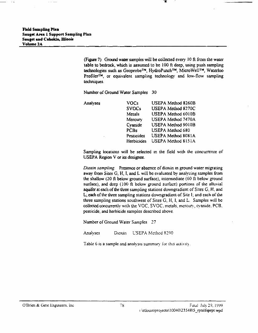
Field Sampling PlanSauget Area 1 Support Sampling PlanSauget and Cabokia, niinouVolume 2A
(Figure 7). Ground water samples will be collected every 10 ft from the watertable to bedrock, which is assumed to be 100 ft deep, using push samplingtechnologies such as Geoprobe™, HydroPunch™, MicroWell™, WaterlooProfiler™, or equivalent sampling technology and low-flow samplingtechniques.
Number of Ground Water S amples 3 0
Analyses VOCs USEPA Method 8260BSVOCs USEPA Method 8270CMetals USEPA Method 601 OBMercury USEPA Method 7470ACyanide USEPA Method 901 OBPCBs USEPA Method 680Pesticides USEPA Method 8081AHerbicides USEPA Method 8151A
Sampling locations will be selected in the field with the concurrence ofUSEPA Region V or its designee.
Dioxin sampling. Presence or absence of dioxin in ground water migratingaway from Sites G, H, I, and L will be evaluated by analyzing samples fromthe shallow (20 ft below ground surface), intermediate (60 ft below groundsurface), and deep (100 ft below ground surface) portions of the alluvialaquifer at each of the three sampling stations downgradient of Sites G, H, andL; each of the three sampling stations downgradient of Site I; and each of thethree sampling stations southwest of Sites G, H, I, and L. Samples will becollected concurrently with the VOC, SVOC. metals, mercury, cyanide, PCB,pesticide, and herbicide samples descnbcd above.
Number of Ground Water S amp les 27
Analyses Dioxm USEPA Method 8290
Table 6 is a sample and analysis summary lor this activity
O'Bnen & Gere Engineers, Inc Final July 29, 1999i:\stlouis\projects\10040\23548V5_rpts\fsprpt.wpd
5. Field activities by area of concern
5.9.2. QA/QC samplesQA/QC samples will consist of one duplicate per ten, or fraction of ten,environmental samples collected and one MSD/MSD or spike duplicate pertwenty, or fraction of twenty, environmental samples collected. Duplicate,MS/MSD, and spike duplicate samples will be submitted for analysis.Duplicate samples are collected to measure consistency of field samplingtechnique. MS/MSD and spike duplicate samples are collected to measurelaboratory quality control procedures. A field blank (or equipment blank)must be submitted to the laboratory with the investigative samples andanalyzed for the same parameters as the investigative samples. The minimumrequired is one per ten, or fraction of ten, environmental samples collected,unless dedicated or disposable sampling equipment is used to collect samples.A trip blank for VOC analysis will be included with each sample coolercontaining environmental samples for VOC analysis that is shipped.
5.9.3. Field proceduresPush point. Using the hydraulic push system of a Geoprobe™, or similarunit, a mill-slotted or stainless steel screen point will be pushed to the watertable. A high-density polyethylene (HDPE) (or Teflon<D-lined or Teflon®)tube will be inserted into the center annular space to approximately one to oneand one-half feet above the bottom of the screen. An appropriate lengthsection of flexible fluoropolymer tubing will be attached to the HDPE tubingusing a barbed connector. The flexible tubing will be connected through thehead of the peristaltic pump. The open end of the flexible tubing will belocated so it can discharge into a purge water container (5-gal bucket) Theperistaltic pump will be turned on at an approximate flowrate of 100 ml/min.The purging will continue for 60 minutes. As the 5-gal discharge bucket fills,it will be replaced with an empty bucket, and the full bucket will be emptiedinto a 5 5-gal drum. At the end of 60 minutes, the pH, conductivity,temperature, and turbidity will be measured and recorded in the field samplingnotebook. If the turbidity is greater than 5 NTU, purging will continue. Oncethe turbidity is at or below 5 NTU or 2 hours have elapsed, ground watersamples will be collected into labeled, pre-preserved (where necessary),laboratory-provided containers. Sample containers for VOC analysis will befilled first. Collected samples will be placed on ice in a cooler, and chain-of-custody procedures will be initiated. The fluoropolymer tubing will bedisconnected from the peristaltic pump. The HDPE tubing will be pulled fromthe center annular space. The flexible tubing and HDPE tubing will then bediscarded into plastic trash bags. Clean sections of push rods will beconnected, the sampling point will be advanced 10 ft, and the samplecollection method will be repeated.
Final July 29, 1999 79 O'Bnen & Gcre Engineers, Inc.i \stlouis\projects\10040\23548\5_rpts\fsprpt wpd
Field Sampling PlanSauget Area 1 Support Sampling PlanSauget and Cahokia, IllinoisVolume 2A
MicroWeH™. It is anticipated the above sampling method will be used asfeasible. However, based on the location of the site within the MississippiRiver flood plain, large gravel or cobbles may be encountered which will stopthe Geoprobe™. Should this occur, Micro Wells™ would be installed to useas the sample collection point. The MicroWells™ will be hydraulicallypushed to the appropriate depth, and the sampling procedure described above,beginning with inserting the tubing through the annular space, will befollowed. Once the sample is collected, the MicroWell™ will be pulled, thescreen point decontaminated according to the method described below, and anew well will be advanced 10 ft further in the same hole. This procedure willbe repeated until reaching bedrock.
Should MicroWell™ installation prove impractical, boreholes will beadvanced using conventional hollow stem auger drilling methods. In thisinstance, the lead auger will have a screened section through which groundwater will flow. A submersible Grundfos Rediflow™ pump will be placedthrough the center of the augers to approximately two feet from the bottom.The pump will have the appropriate length of HOPE tubing attached. Thetubing will discharge to the 5-gal bucket at before. The sample will becollected from the tubing, filling the VOC containers first. Once all thesamples are collected, the augers will be advanced 10 ft; a new, clean sectionof tubing will be attached to the pump; and additional samples will becollected. This procedure will be repeated to bedrock. All Geoprobe™,MicroWell™, or Waterloo Profiler™ holes or casings will be sealed withgrout from the bottom up after completion of sampling at each location. APID, an explosimeter, and a RAM will be used on a continuous basis tomonitor these activities.
Sampling equipment decontamination.• Brush-wash reusable sampling equipment in a bucket or tub using a
tnsodium phosphate (TSP), or other commercial detergent, solution (2 Ibof TSP per 10 gal of clean water). Completely brush the entire exteriorsurface of the article undergoing decontamination Wash interior wettedsurfaces as required. Rinse the item with copious quantities of potablewater, followed by a distilled water nnse.
• Rinse reusable sampling equipment used to collect environmental mediafor metals analysis in a dilute nitnc acid solution, followed by a distilledwater nnse.
O'Bnen •& Gcre Engineers, Inc. 80 Final July 29, 1999i:\stlouis\projects\10040\23548\5_rpls\fsprpt.wpd
5. Field activities by area of concern
Air-dry sampling equipment on a clean, non-plastic surface in a wellventilated, uncontaminated environment. If the sampling device is not tobe used immediately, wrap it in aluminum foil and place it in a plastic bagor storage container.
Contain rinse waters in a plastic tub with a lid. Empty the contents of thistub daily into a 55-gal drum located at the investigation-derived wastestorage area.
5.9.4. DocumentationA field notebook will be kept for the alluvial aquifer sampling. At a minimum,the notebook will include project name and number; date and time; weatherconditions; sampler's name; sample location, pH, conductivity, temperature,PID, explosimeter, RAM, and turbidity measurements; changes in samplingtechnique; depths of sample collection; limiting field conditions; problemsencountered; subcontractor personnel on-site; USEPA Region V personnelon-site; and other personnel on-site. Notation of USEPA Region V acceptanceof sampling locations will also be included in the field notebook.
5.10. Bedrock ground water sampling
5.10.1. Rationale/designAs directed by USEPA Region V, three bedrock wells will be installed in themiddle of Sites G, H, and I in order to evaluate the vertical extent of organicand inorganic constituents migrating away from these sites Telescopingsurface casing will be installed to depths of 5 ft and 20 ft below the fillmaterial and 5 ft into bedrock in order to minimize carry-down of site-relatedconstituents during ground water sample collection and vertical migration ofsite-related constituents after completion of sampling
Bedrock will be cored to a depth of 20 ft below the telescoping casing. Coreswill be digitally photographed in color against a scale and evaluated forporosity by examination and pctrographic thin sections A ground watersample will be collected from each core hole
Final July 29, 1999 81 O'Bnen & Gere Engineers, Inc.i:\stlouis\projects\10040\23548\5_rpu\fspiptwpd
Fkld Sampling PlanSauget Area 1 Support Sampling PlanSauget and Cahokia, IllinoisVolume 2A _______
Sampling locations will be based on the fill area shallow ground watersampling results (section 5.7.1).
Number of Ground Water Samples 3
Analyses VOCs USEPA Method 8260BSVOCs USEPA Method 8270CMetals USEPA Method 601 OBMercury USEPA Method 7470ACyanide USEPA Method 901 OBPCBs USEPA Method 680Pesticides USEPA Method 8081AHerbicides USEPA Method 8151ADioxin USEPA Method 8290
Sampling locations will be selected in the field with the concurrence ofUSEPA Region V or its designee.
Table 7 is a sample and analysis summary of this activity.
5.10.2. QA/QC samplesQA/QC samples will consist of one duplicate per ten, or fraction of ten,environmental samples collected and one MSD/MSD or spike duplicate pertwenty, or fraction of twenty, environmental samples collected. Duplicate,MS/MSD, and spike duplicate samples will be submitted for analysis.Duplicate samples are collected to measure consistency of field samplingtechnique. MS/MSD and spike duplicate samples are collected to measurelaboratory quality control procedures. A field blank (or equipment blank)must be submitted to the laboratory with the investigative samples andanalyzed for the same parameters as the investigative samples. The minimumrequired is one per ten, or fraction of ten, environmental samples collected,unless dedicated or disposable sampling equipment is used to collect samples.A trip blank for VOC analysis will be included with each sample coolercontaining environmental samples for VOC analysis that is shipped.
O'Bnen & Gere Engineers, Inc 82 Final July 29, 1999i:\stlouis\projects\10040V23548\5_rpts\fsprpt.wpd
5. Field activities by area of concern
5.10.3. Field proceduresMud rotary drilling methods will be used to drill the boreholes to set thetelescoping casing and to drill 5 ft into the top of bedrock. Coring will then beaccomplished using wireline coring barrels to generate a 2-inch minimum core.Coring will continue for 20 ft into the bedrock. Core samples will bephotographed and described on test boring logs. Descriptions will follow theprocedures outlined below. After coring is completed, a ground water samplewill be collected from the bedrock core hole. Sampling will be accomplishedusing a Grundfos Rediflow™ pump, control box, and electrical generator.Sampling will be accomplished following applicable procedures outlined i•:.section 5.7.3. A PID, an explosimeter, and a RAM will be used on acontinuous basis to monitor these activities.
Once sample collection is completed, the pump and tubing will be pulled. Thetubing will be placed into a plastic trash bag and disposed of in the generalwaste dumpster. The bore hole will be abandoned by filling the annular spacewith a cement and bentonite grout from bottom to top. The surface top 2 ftwill be restored with soil and seeded. The drill ng will be moved to thedecontamination station and steam cleaned. Solids will be placed into acontainer for transport to the soils disposal collection container.
Sampling equipment decontamination.• Brush-wash reusable sampling equipment in a bucket or tub using a
tnsodium phosphate (TSP), or other commercial detergent, solution (2 Ibof TSP per 10 gal of clean water). Completely brush the entire exteriorsurface of the article undergoing decontamination. Wash interior wettedsurfaces as required. Rinse the item with copious quantities of potablewater, followed by a distilled water nnse.
• Rinse reusable sampling equipment used to collect environmental mediafor metals analysis in a dilute nitric acid solution, followed by a distilledwater nnse.
• Air-dry sampling equipment on a clean, non-plastic surface in a wellventilated, uncontammated environment. If the sampling device is not tobe used immediately, wrap it in aluminum foil and place it in a plastic bagor storage container.
• Contain rinse waters in a plastic tub with a lid. Empty the contents of thistub daily into a 55-gal drum located at the investigation-denved wastestorage area.
Final July 29, 1999 83 O'Bnen & Gere Engineers, Inci:\stlouis\projects\10040\23548\5_rpts\fsprptwpd
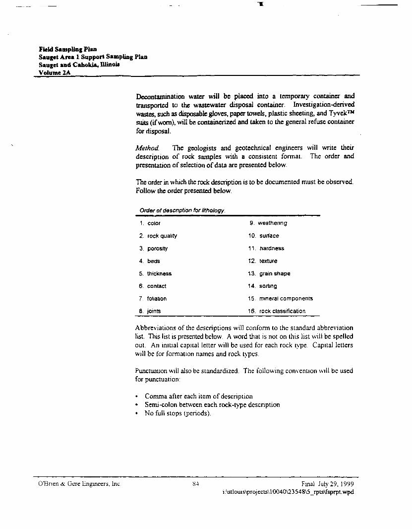
Field Sampling PlanSauget Area 1 Support Sampling PlanSauget and Cabokia, IllinoisVolume 2A _____
Decontamination water will be placed into a temporary container andtransported to the wastewater disposal container. Investigation-derivedwastes, such as disposable gloves, paper towels, plastic sheeting, and Tyvek™suits (if worn), will be containerized and taken to the general refuse containerfor disposal.
Method. The geologists and geotechnical engineers will write theirdescription of rock samples with a consistent format. The order andpresentation of selection of data are presented below.
The order in which the rock description is to be documented must be observed.Follow the order presented below.
Order of description for litholagy.
1. color
2. rock quality
3. porosity
4. beds
5. thickness
6 contact
7. foliation
8. joints
9. weathering
10. surface
11. hardness
12. texture
13. grain shape
14. sorting
15. mineral components
16. rock classification
Abbreviations of the descriptions will conform to the standard abbreviationlist. This list is presented below A word that is not on this list will be spelledout. An initial capital letter will be used for each rock type Capital letterswill be for formation names and rock types.
Punctuation will also be standardized. The following convention will be usedfor punctuation:
• Comma after each item of description• Semi-colon between each rock-type description• No full stops (periods).
OTSnen &. Gcre Engineers, Inc 84 Final July 29, 1999i:\stlouis\projects\10040\23548\5_rpts\fsprpt.wpd
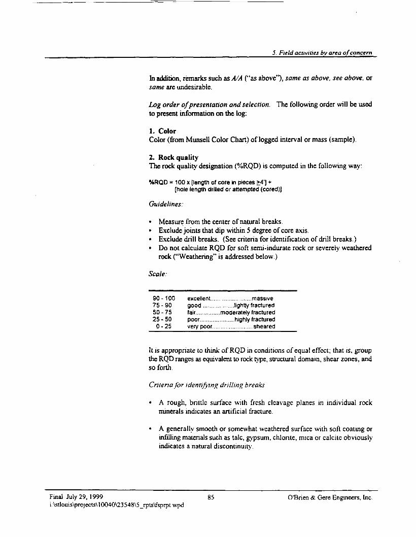
5. Field activities bv area of concern
In addition, remarks such as A/A ("as above"), same as above, see above, orsame arc undesirable.
Log order of presentation and selection. The following order will be usedto present information on the log:
1. ColorColor (from Munsell Color Chart) of logged interval or mass (sample).
2. Rock qualityThe rock quality designation (%RQD) is computed in the following way:
%RQD = 100 x (length of core in pieces >4'] +[hole length drilled or attempted (cored)]
Guidelines:
• Measure from the center of natural breaks.• Exclude joints that dip within 5 degree of core axis.• Exclude drill breaks. (See criteria for identification of drill breaks.)• Do not calculate RQD for soft semi-indurate rock or severely weathered
rock ("Weathering" is addressed below.)
Scale:
90 -100 excellent.........................massive75 - 90 good....................lightly fractured50 - 75 fair...............moderately fractured25 - 50 poor.....................highly fractured
0 -25 very poor.........................sheared
It is appropriate to think of RQD in conditions of equal effect; that is, groupthe RQD ranges as equivalent to rock type, structural domain, shear zones, andso forth.
Criteria for identifying drilling breaks
• A rough, brittle surface with fresh cleavage planes in individual rockminerals indicates an artificial fracture.
• A generally smooth or somewhat weathered surface with soft coating orinfilling materials such as talc, gypsum, chlonte, mica or calcitc obviouslyindicates a natural discontinuity
Final July 29, 1999 85 O'Bnen & Gere Engineers, Inci:\stlouis\prpjects\10040\23548\5_rpts\fsprpt.wpd
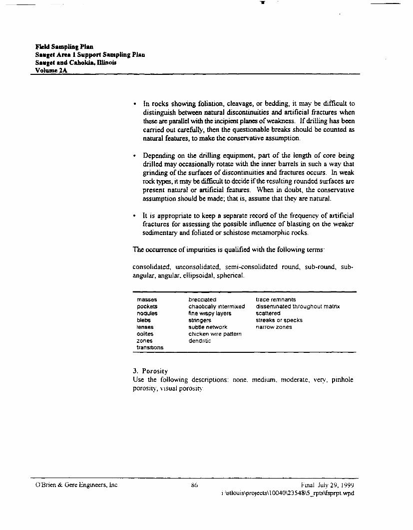
Field Sampling PlanSauget Area 1 Support Sampling PlanSauget and Cahokia, DUnouVolume 2A
• In rocks showing foliation, cleavage, or bedding, it may be difficult todistinguish between natural discontinuities and artificial fractures whenthese are parallel with the incipient planes of weakness. If drilling has beencarried out carefully, then the questionable breaks should be counted asnatural features, to make the conservative assumption.
• Depending on the drilling equipment, part of the length of core beingdrilled may occasionally rotate with the inner barrels in such a way thatgrinding of the surfaces of discontinuities and fractures occurs. In weakrock types, it may be difficult to decide if the resulting rounded surfaces arepresent natural or artificial features. When in doubt, the conservativeassumption should be made; that is, assume that they are natural.
• It is appropriate to keep a separate record of the frequency of artificialfractures for assessing the possible influence of blasting on the weakersedimentary and foliated or schistose metamorphic rocks.
The occurrence of impurities is qualified with the following terms:
consolidated, unconsolidated, semi-consolidated round, sub-round, sub-angular, angular, ellipsoidal, spherical
massespocketsnodulesblebslensesooliteszonestransitions
brecciatedchaotically intermixedfine wispy layersstringerssubtie networkchicken wire patterndendritic
trace remnantsdisseminated throughout matnxscatteredstreaks or specksnarrow zones
3. PorosityUse the following descriptions: none, medium, moderate, very, pinholeporosity, visual porosity.
O'Bnen &. Gere Engineers, Inc 86 Final July 29, 1999i:\stlouis\projects\10040\23548\5_rpts\fsprpt.wpd
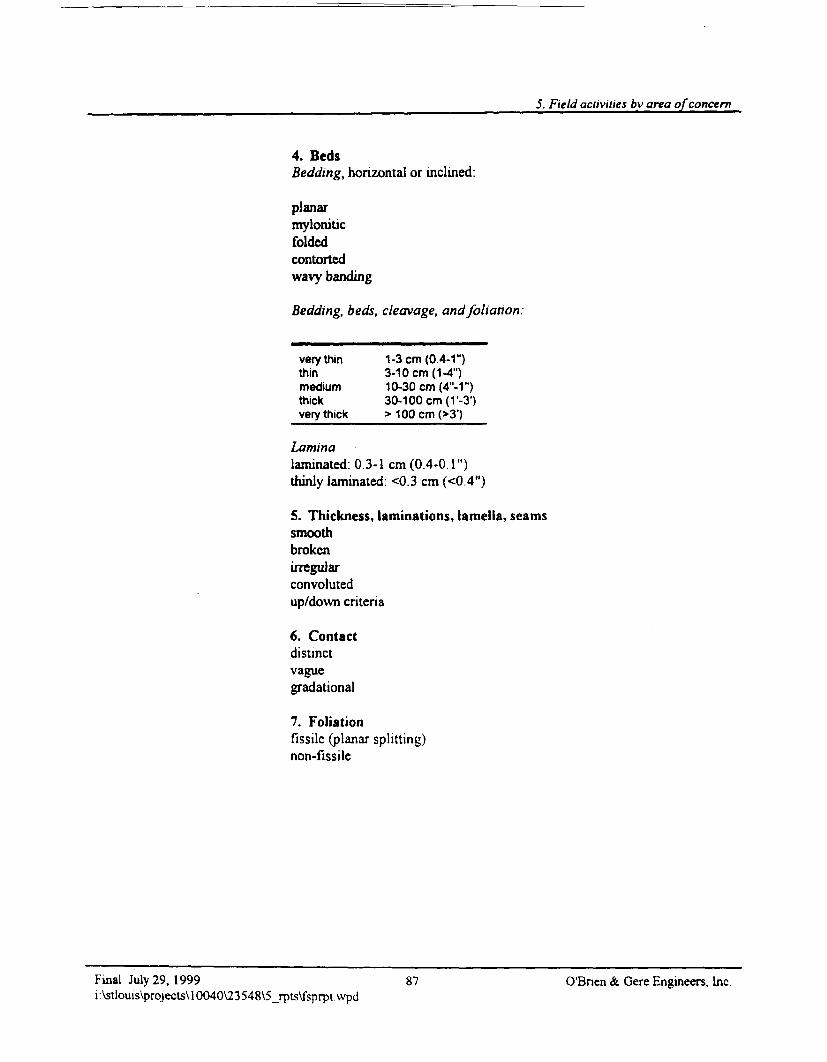
5. Field activities by area of concern
4. BedsBedding, hohzontal or inclined:
planarmyloniticfoldedcontortedwavy banding
Bedding, beds, cleavage, and foliation:
very thin 1 -3 cm (0.4-1")thin 3-1 Ocm (1-4")medium 10-30 cm (4"-1M)thick 30-100 cm (V-31)very thick___> 100 cm (>3')
Laminalaminated: 0.3-1 cm (0.4-0.1")thinly laminated. <0.3 cm (<0.4")
5. Thickness, laminations, lamella, seamssmoothbrokenirregularconvolutedup/down criteria
6. Contactdistinctvaguegradational
7. Foliationfissile (planar splitting)non-fissile
Final July 29, 1999 87 O'Bnen & Gere Engineers, Inc.i:\stlouis\projects\10040\23548\5_rpts\fsprptvvpd
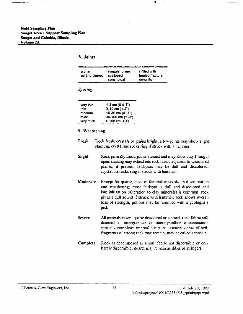
Field Sampling PlanSauget Area 1 Support Sampling PlanSauget and Cahokia, IllinoisVolume 2A
8. Joints
planarparting planes
irregular breakscallopedconchoidal
infilled withhealed fracturemylonitic
Spacing
very thinthinmediumthickvery thick
1-3 cm (0.4-1")3-10 cm (1-4")10-30 cm (4"-1")30-100 cm (1'-3')> 100cm(>3')
9. Weathering
Fresh Rock fresh; crystals or grains bright; a few joints may show slightstaining; crystalline rocks ring if struck with a hammer.
Slight Rock generally fresh; joints stained and may show clay filling ifopen; staining may extend into rock fabric adjacent to weatheredplanes; if present, feldspars may be dull and discolored;crystalline rocks ring if struck with hammer.
Moderate Except for quartz, most of the rock mass sh.--».-s discolorationand weathering; most feldspar is dull and discolored andkaolinitization (alteration to clay minerals) is common; rockgives a dull sound if struck with hammer; rock shows overallloss of strength, potions may be removed with a geologist'spick.
Severe All minerals except quartz discolored or stained; rock fabric stilldiscernible; intergranular or imercrystallme disassociationvirtually complete; internal structure essentially that of soil;fragments of strong rock may remain; may be called saprolite.
Complete Rock is decomposed to a soil; fabric not discernible or onlybarely discernible; quartz may remain as dikes or stringers.
O'Brien & Gere Engineers, Inc. 88 Final July 29, 1999i:\stlouis\projects\l0040\23548\5_rpts\fsprpt.wpd
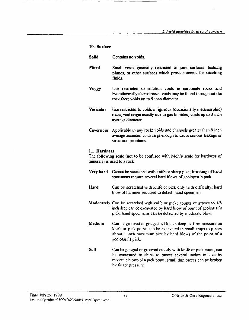
5. Field activities by area of concern
10. Surface
Solid Contains no voids.
Pitted Small voids generally restricted to joint surfaces, beddingplanes, or other surfaces which provide access for attackingfluids.
Vuggy Use restricted to solution voids in carbonate rocks andhydrolhermaUy altered rocks; voids may be found throughout therock face; voids up to 9 inch diameter.
Vesicular Use restricted to voids in igneous (occasionally metamorphic)rocks, void origin usually due to gas bubbles; voids up to 3 inchaverage diameter.
Cavernous Applicable in any rock; voids and channels greater than 9 inchaverage diameter; voids large enough to cause serious leakage orstructural problems.
11. HardnessThe following scale (not to be confused with Moh's scale for hardness ofminerals) is used to a rock:
Very hard Cannot be scratched with knife or sharp pick; breaking of handspecimens require several hard blows of geologist's pick.
Hard Can be scratched with knife or pick only with difficulty; hardblow of hammer required to detach hand specimen.
Moderately Can be scratched with knife or pick; gouges or groves to 1/8inch deep can be excavated by hard blow of point of geologist'spick; hand specimens can be detached by moderate blow.
Medium Can be grooved or gouged 1/16 inch deep by firm pressure onknife or pick point: can be excavated in small chips to piecesabout 1 inch maximum size by hard blows of the point of ageologist's pick.
Soft Can be gouged or grooved readily with knife or pick point; canbe excavated in chips to pieces several inches in size bymoderate blows of a pick point, small thin pieces can be brokenby finger pressure.
Final July 29, 1999 89 O'Bnen & Gere Engineers, Inc.i:\stlouis\projccts\10040\23548\5_rpts\fsprptwpd
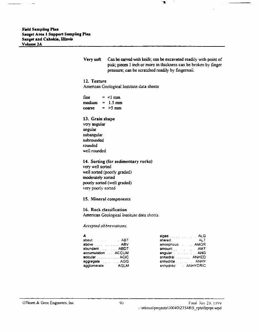
Field Sampling PlanSaugct Area 1 Support Sampling PlanSauget and Cahoida, Ulinoi*Volume 2A
Very soft Can be carved with knife; can be excavated readily with point ofpick; pieces 1 inch or more in thickness can be broken by fingerpressure; can be scratched readily by fingernail.
12. TextureAmerican Geological Institute data sheets
fine = <1 mmmedium = 1.5 mmcoarse = >5 mm
13. Grain shapevery angularangularsubangularsubroundedroundedwell rounded
14. Sorting (for sedimentary rocks)very well sortedwell sorted (poorly graded)moderately sortedpoorly sorted (well graded)very poorly sorted
15. Mineral components
16. Rock classificationAmerican Geological Institute data sheets.
Accepted abbreviations.
Aaboutaboveabundant .accumulationacicular . . . . .aggregateagglomerate
. . ABT. . ABV. . ABDTACCUM. . ACIC
. AGGAGLM
algae . . . .altered .amorphousamountangular .anhedral . .anhydrite . .anhydritic
ALGALT
AMORAMT
. . .. . ANGANHED
ANHYANHYDRIC
O'Bnen & Gere Engineers, Inc. 90 Final Jui> 29, 1 999i \stlouis\projects\ 10040\23548V5_rpts\fsprpt.wpd
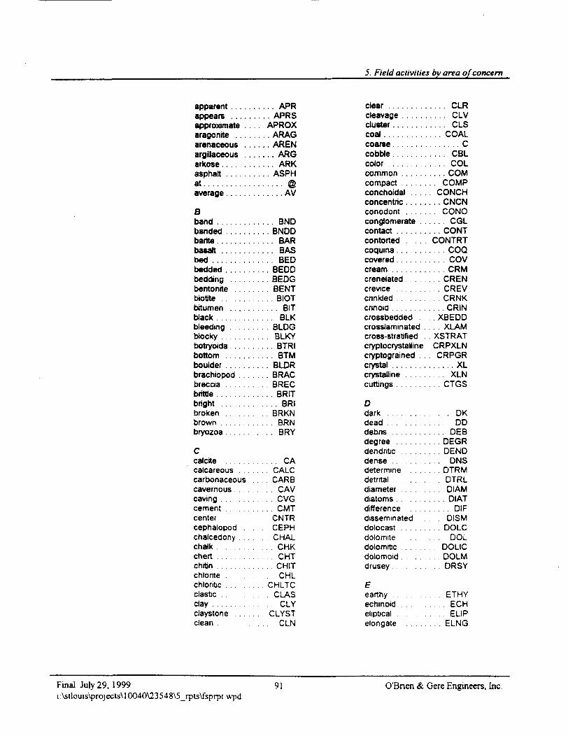
5. Field activities by area of concern
apparent . . . . . .appears . . . . . .approximatearagonitearenaceous . . .argillaceousarkose . . . . . . .asphaltat . . . . . . . . . . . .average
Bband . . . . . . . . .bandedbarite . . . . . . . . .basaltbed . . . . . . . . . .bedded . . . . . . .bedding . . .bentonrtebiotte . . . . . . . .bitumen . . . . . .black . . . . . . . . .bleeding . . . . .blocky . . . . . . . .botryoida . . . . . .bottom . . . . . . .boulder . . . . .brachiopod ...breccia . . . . .brittle . . . . . . . . .bright ...broken . . . . . . .brown . . . . . . . .bryozoa
Ccalcitecalcareouscarbonaceouscavernouscaving . . . . . . . .cementcenter .cephalopodchalcedonychalk . . . . . . . . .chert . . . . . . . . .chrtin . . . .chlonte . . . . . . .chloritic . . .clastic .clay . . . . . . . . . .claystone . . . .clean . . . . .
APR
. . . APRS
. APROX
. . . ARAG
. . . AREN
.... ARG
.. . . ARK
. . . ASPH
. . . . . . AV
. . . . BND
. . . BNDD
. . . . BARBAS
. . . . BED
. . . BEDD
. . . BEDG. . BENT
. . . . BIOT
. . . . . BIT
. . . . BLK
. . . BLDG
. . . BLKY
. . . . BTRI
. . . . BTM
. . . BLDR. . BRAC
. . . BREC
. . . . BRIT. . . BRI. . BRKN
. . BRN. . . . BRY
. . . . . CA
. . CALC
. . CARB. . . C A V
. . CVG.. . CMT
. CNTRCEPH
. CHAL
... CHK
. . CHT. . . . CHIT
. CHL. CHLTC
CLAS. . . . CLY
CLYST. . . . CLN
clear . . . . . . . . .cleavage . . . . . .clustercoal . . . . . . . . . .coarse . . . . . . . .cobble . . . . . . . .color . . . . . . . . .common . . . . . .compact . . . . . .conchoidal . . . .concentric . . . . .conodontconglomerate . .contact . . . . . . .contorted . . . . .coquina . . . . . . .covered . . . . . .cream . . . . . . . .crenelated . . . .crevice . . . . . . .cnnkled . . . . . . .cnnoid . . . . . . . .crossbeddedcrosslaminated .cross-stratified .cryptocrystallinecryptogramed . .crystal . . . . . . . .crystalline . . .cuttings . . . . . . .
Ddark . . . . . . . . .dead . . .debnsdegree . . . . . . .dendritic . . . . . .dense . . . . . . . .determine . . .detrital . . . . . .diameter . . . . . .diatoms . . . . . .difference . . . . .disseminateddolocast . . . . . .dolomite . . . .dolomrtc . . . . .dolomoid . . . .drusey . . .
Eearthy . . . . . .echinoid . . . . . .eliptical . . .elongate . . .
. . . . CLR
. . . . CLV
.... CLS
. . . COAL
. . . . . . . C
. . . . CBL
. . . . COL
. . . . COM
. . COMP
. CONCH
. . . CNCN
. . CONO
. . . . CGL
. . . CONTCONTRT
. . COO... COV
. . CRM. . . CREN
. CREVCRNK
. . . . CRIN
. . XBEDDXLAM
XSTRATCRPXLN
. CRPGR
. . . . . . XL
. XLN
. . CTGS
. . . . . DKDD
. . . . DEB
. . . DEGR
. . . DEND
. . . DNS
. DTRM. . DTRL
. . . DIAM. DIAT
. . DIF. DISM
. . . DOLC
. . . DOL. DOLIC
. . . DOLMDRSY
. ETHY. . . ECH. . . ELIP. ELNG
Final July 29, 1999i:\stlouis\projects\10040\23548\5_rpts\fsprptwpd
91 O'Bncn & Gere Engineers, Inc.
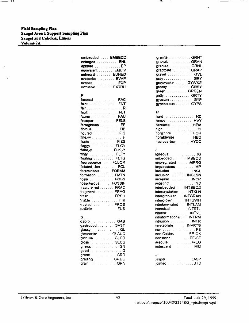
Field Sampling PlanSauget Area 1 Support Sampling PlanSauget and Caholtia, IllinoisVolume 2A ____
embedded . . . . EMBEDDenlarged . . . . . . . . . . ENLepidote . . . . . . . . . . . . . EPequivalent . . . . . . . EQUIVeuhedral . . . . . . . EUHEDevaporitic . . . . . . . . EVAPexpose . . . . . . . . . . . EXPextrusive . . . . . . . . EXTRU
Ffaceted . . .f a i n t . . . . . . .f a i r . . . . . . . .fau l t . . . . . . .fauna . . . .feldspar....ferruginous .fibrous....figured . . . .fine,-ly . . . . .fissile . . .flaggyflake,-yflinty . . . . . .floating . . .fluorescencefoliated, -ionforaminiferaformation . .fossil . . .fossiliferousfracture,-edfragmentfreshfriablefrostedfusilinid .
Ggabrogastropodglassyglauconrteglobularglossgnetss . . . .goodgradegradinggrain . . .
. .. FAC
... FNT
. . . . . . R
. . . . FLT
... FAU
. . FELS
. ... . FE
.. .. FIB
. . . . FIG
. . . . . . F. . FISS. FLGY
. FLK.-Y
. . . FLTY
.. FLTG
. FLUOR
. . . FOLFORAM
. . FMTN
. . FOSSFOSSIF
. . FRAC
. FRAGFRSH
. FRIFROS
FUS
. . GABCAST
. . . . GLGLAUC
GLOBGLOS
. . GN
. . . . . GGRD
GRDGCRN
granite . . . . . . . . . GRNTgranular . . . . . . . . . GRANgranule . . . . . . . . . . GRNLgraptolite......... GRAPgravel . . . . . . . . . . . . GVLg r a y . . . . . . . . . . . . . . GRYgraywacke . . . GYWKEgreasy . . . . . . . . . . . GRSYgreen . . . . . . . . . GREENgntty . . . . . . . . . . . . GRTYgypsum . . . . . . . . . . . GYPgypsiferous . . . . . . . GYPS
Hhard . . . . . .heavy ...hematite . .high . . . . . . .horizontalhornblendehydrocarbon
.. HD
. HVY
. HEM
... HIHORHBDHYDC
igneousimbeddedimpregnated .impressionsincluded . . . . . .inclusion . . . . . .increase . . . . . .indistJnct . . .interbedded .intercrystallmeintergranularintergrown . . . .interlammatedinterstitialinterval . . . . . . .informational .intrusion . . . . . .invetebrateiron . . . . . . . . . .iron Oxidesironstoneirregulariridescent
Jjasperjointed . . . . . . .
. . . . . . . IG. IMBEDD
. IMPRGIMP
INCL. INCLSN... INCR
. . . . I N DINTBEDD. INTXLNINTGRANINTGWNINTLAMINTSTL
. . . INTVL
. . INTRM
. . . . INTRINVRTB
. . . . . . F EFE-OXFE-ST
.. . IREGIRID
JASP. . . . . . J T D
O'Bnen & Gere Engineers, Inc. 92 Final July 29, 1999i:\stlouis\projects\10040\23548\5_rpts\fsprpt.wpd
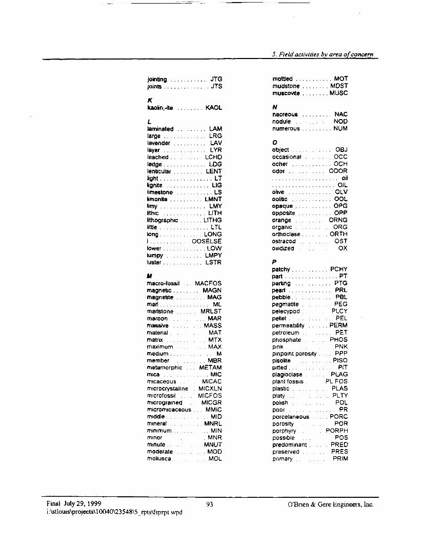
5. Field activities by area of concern
jointing . . . . . .joints . . . . . . . .
Kkaolin,-ite . . . . .
Llaminated . . . . .large . . . . . . . . .lavender . . . . . .layer . . . . . . . . .leached . . . . . .ledge .........lenticular . . . . . .light . . . . . . . . . .lignite . . . . . . . .limestone . . . . .limonlte .......limy . . . . . . . . . .lithic . . . . . . . . .lithographic . . .little . . . . . . . . . .long . . . . . . . . . .1 . . . . . . . . . . . .lower . . . . . . . . .lumpy . . . . . . . .luster . . . . . . . . .
Mmacro-fossil . .magnetc . . . .magnetite .marl . . . . . . . . . .martstonemaroon . . . . . . .massive . . . . . .matenalmatrix . . . . . . . .maximummedium . . . . . . .member . . . . . .metamorphicmica . . . . . . . . .micaceousmicrocrystalhnemicrofossil .micrograinedmicromicaceousmiddle . . . . . . . .mineral . . . . . . .minimum . . . . . .minorminute . . . . . . . .moderatemollusca
. . . . JTG
. . . . . JTS
... KAOL
. . . . LAM. . LRG
. . . . LAV1 VP
. . . LCHD
. . . . LOG
. . . LENT
. . . . . . LT
. . . . . LIGI ̂
. . . LMNT
. . . . LMY
. . . . LITH
. . . LITHG
. . . . . LTL
. . LONGOOSELSE. . . . LOW. . . LMPY
. . LSTR
MACFOS. . MAGN
MAGML
MRLST. . MAR
MASSMAT
. . . M T X
. . . . MAX
. . . . . . M
. . . . M B RMETAM
.MICMICAC
MICXLNMICROSMICGR
MMIC. . . . . M I D
. . MNRL. . . . . M I N
MNRMNUT
MODMOL
mottled ........mudstone . . . . . .muscovite . . . . . .
Nnacreous . . . . . .nodule . . . . . . .numerous . . . . . .
Oobject . . . . . . . . .occasional . . . .ocher . . . . . . . . .odor . . . . . . . . . .
olive . . . . . . . . . .ooliticopaque . . . . .opposite . . . . . .orange . . . . . . . .organic . . . . . . . .orthoclaseostracodoxidized . . . . . . .
Ppatchy . . . . . . . . .part . . . . . . . . . . .parting . . . . . .peartpebble . . . . . . . . .pegmatite . . . . . .pelecypod .pellet . . . . . . . . . .permeabilitypetroleumphosphatepink . . . .pinpoint porositypisolite . . .pitted . . . . . . .plagioclaseplant fossilsplasticplatypolish . . . . . . . . .poor .porcelaneousporosity . . . . . . . .porphyrypossiblepredominantpreserved . . . . . .primary . . . . .
. . . MOTMOST
. . MUSC
. . . NACNOD
. . . NUM
... OBJ
. . . occ
. . . OCHODOR
. . . . . oil
. . . . OIL
. . . OLV
. . . OOL
. . OPG. OPPORNG
ORGORTH
OSTOX
. . PCHY
. . . . . PTPTG
. . . PRL. PBL
PEG. PLCY. P E L
. . PERM. PET
. . PHOSPNK
. . PPP
. . . PISO
. . . P I T
. PLAGPLFOS
PLASPLTYPOL
.. . PR. PORC
PORPORPH
POS. PRED
. PRESPRIM
Final July 29, 1999i:\stlouis\projects\10040\23548\5_rpis\fsprpt\vpd
93 O'Bnen & Gere Engineers, Inc.
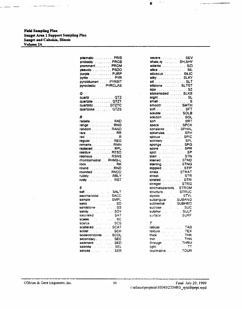
Field Sampling PlanSauget Area 1 Support Sampling PlanSauget and Cahokia, DlinoisVolume 2A
prismatic . . . . .probablyprominent . . . .pseudo . . . . . .purple . . . . . . .pyrite . . . . . . . .pyrobitumen . .pyroclastic
0quartz . . . . . . .quartzite . . . . .quartz/tic . . . .quartzose . . . .
Rradiaterange . . . . . . .random ...rare . . . . . . . . .r e d . . . . . . . . .regular . . . .remains . . . . .replaced . . . .residue . . . . . .resinous .rhombohedral .rock . . . . . . . .round . . . . . . .roundedrubWy . . . . . . .rusty . . . . . . . .
Ssalt . . . . . . . . .saccharoidal . .samplesandsandstonesandysaturatedscalesscarcescatteredschist . . . . . . .scolecondontssecondary .sedimentselenrtesenate
. . . . . PRIS
.... PROB
... PROM
. . . . PSDO
. . . . PURP
. . . . . PYR
. . PYRBITPYRCLAS
. . . . . QTZ
. . . . QTZT
. . . QTZTC
. . . . QTZS
. . . . . RAD
. . . . . RNG
. . . RAND
. . . . . . RR
. . . . . . . . R. . . R E G
. . . . . RMN
. . . . . RPL
. . . . RESD... RSNS
. . RHMB-L
. . . . . . RK
. . . . . RND
... RNDD
. . . . RBLY
. . . . . RST
. . . . SALT. SACC
. . . . SMPL
. . . . . . S D. . . . . s s
. . . S D YSAT
. . . . SCSCS
SCAT. . . S C H
. . . SCOL
. . . . . SEC. . . . SED
. . . . SEL. SER
severe . . . . . . . .shale,-ty . . . . . .siderrtesilica . . . . . . . . .siliceous . . . . . .silky . . . . . . . . . .slit . . . . . . . . . . .siltstone . . . .size . . . . . . . . . .slickensided . . .slight . . . . . . . . .small . . . . . . . . .smooth . . . . . . .soft . . . . . . . . . .soluble . . . . . . .solution . . . . . . .sort . . . . . . . . . .speck . . . . . . . .sphaleritespherulesspiculesplinterysponge . . . .sporespot . . . . . . . . . .stain . . . . . .stained . . . . . . .staining . . . . .stippled . . .strata .streakstriated . . . . . .stringer . . . . . . .stromatoparoidsstructure . . . . . .styolite .subangularsubhedralsucrose .sulphur . . .surface
rtabulartexture . . .thick . . . . . . . . .thin . . . . . . . . . .throughtighttourmaline . . . . .
... SEV. SH.SHY. . . . . SID. . . . SIL. . . SILIC. . . SLKY. . . . . SLT. . SLTST. . . . . . SZ. . . SLKS. . . . . . SL. . . . . . . S. . SMTH. . . . SFT... SOLB. . . . SOL. . . . SRT. SPCK. . SPHAL. . . . SPH... SPIC
SPL. . . . SPG. . SPR
. . . . . . SP
. . . S T N. . STND
. . . STNG. STIP
. STRAT. . . S T R. . . . STRI
. . STRGSTROM
. STRUCSTYL
SUBANGSUBHED
. . . . sueSULFSURF
. . . . TAB
. . . T E X. THK
.. . THN. THRU
TTTOUR
OBnen & Gere Engineers, Inc. 94 Final July 29, 1999i:\stlouis\prqjects\l0040\23548\5_rpts\fsprpt.wpd
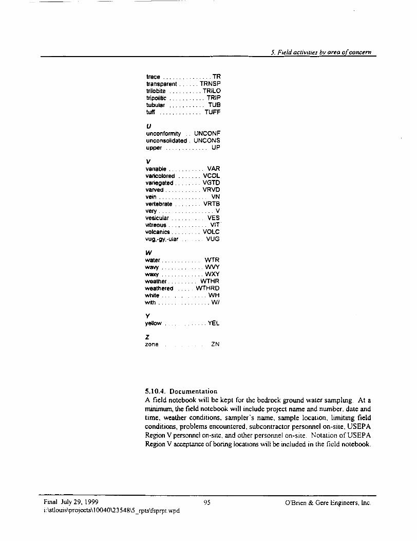
5. Field activities bvareg of concern
trace . . . . . . . . . . . . . . . TRtransparent . . . . . . TRNSPtrilobite . . . . . . . . . . TRILOtripoirtic . . . . . . . . . . . TRIPtubular . . . . . . . . . . . TUBtuff . . . . . . . . . . . . . TUFF
Uunconformity . . UNCONFunconsolidated . UNCONSupper . . . . . . . . . . . . . UP
Vvanabte . . . . . . . . . . . VARvaricolored . . . . . . . VCOLvariegated . . . . . . . . VGTDvarved . . . . . . . . . . . VRVDvein . . . . . . . . . . . . . . . VNvertebrate . . . . . . . VRTBvery . . . . . . . . . . . . . . . . . Vvesicular . . . . . . . . . . VESvitreous . . . . . . . . . . . . VITvolcanics. . . . . . . . . VOLCvug,-gy,-ular . . . . . . . VUG
Ww a t e r . . . . . . . . . . . . . WTRwavy . . . . . . . . . . . . . WVYwaxy . . . . . . . . . . . . . WXYweather . . . . . . . . . WTHRweathered . . . . . WTHRDwhite . . . . . . . . . . . . . . WHwith . . . . . . . . . . . . . . . . W/
Yyellow . . . . . . . . . . . . . YEL
Zzone ZN
5.10.4. DocumentationA field notebook will be kept for the bedrock ground water sampling. At aminimum, the field notebook will include project name and number, date andtime, weather conditions, sampler's name, sample location, limiting fieldconditions, problems encountered, subcontractor personnel on-site, USEPARegion V personnel on-site, and other personnel on-site Notation of USEPARegion V acceptance of bonng locations will be included in the field notebook.
Final July 29, 1999 95 O'Bnen & Gere Engineers, Inc.i:\stiouis\projects\10040\23548\5_rpts\fsprptwpd
Field Sampling PlanSauget Area 1 Support Sampling PlanSauget and Cahokia, IllinoisVolume 2A
Test boring logs will be completed for the core description. Ground watersampling logs will be completed for the ground water sample. The fieldnotebook will also note the sections of core sent for petrographic analysis.Chain-of-custody procedures will be followed for both the ground watersamples and the core sections.
5.11. Shallow residential area ground water sampling
5.11.1. Rationale/designEcology and Environment (1998) identified several homes on Walnut Streetand Judith Lane with private water wells. Shallow ground water samples willbe collected at two sampling stations to evaluate if site-related constituents aremigrating from Dead Creek toward these domestic wells (Figure 7). Onesampling station will be located at the end of Walnut Street, and the othersampling station will be located on the east bank of Dead Creek at JudithLane. Ground water samples at each of the two locations will be collected atthe water table and at depths of 20 and 40 ft below ground surface whichbracket the typical completion depth of domestic wells in southern Illinois.Push sampling technologies such as Geoprobe™, HydroPunch™,MicroWcll™, Waterloo Profiler™, or equivalent sampling technology andlow-flow sampling techniques will be used to collect six ground watersamples.
O'Bnen & Gere Engineers, Inc. 96 Final July 29, 1999i:\stlouis\projects\10040\23548\5_rpts\fsprpt.wpd
5. Field activities by area of concern
Number of Ground Water S amples 6
Analyses VOCs USEPA Method 8260BSVOCs USEPA Method 8270CMetals USEPA Method 601 OBMercury USEPA Method 7470ACyanide USEPA Method 901 OBPCBs USEPA Method 680Pesticides USEPA Method 8081AHerbicides USEPA Method 8151ADioxin USEPA Method 8290
Sampling locations will be selected in the field with the concurrence ofUSEPA Region V or its designee.
Table 8 is a sample and analysis summary of this activity.
5.11.2. QA/QC samplesQA/QC samples will consist of one duplicate per ten, or fraction of ten,environmental samples collected and one MSD/MSD or spike duplicate pertwenty, or fraction of twenty, environmental samples collected. Duplicate,MS/MSD, and spike duplicate samples will be submitted for analysis.Duplicate samples are collected to measure consistency of field samplingtechnique. MS/MSD and spike duplicate samples are collected to measurelaboratory quality control procedures. A field blank (or equipment blank)must be submitted to the laboratory with the investigative samples andanalyzed for the same parameters as the investigative samples. The minimumrequired is one per ten, or fraction of ten, environmental samples collected,unless dedicated or disposable sampling equipment is used to collect samples.A trip blank for VOC analysis will be included with each sample coolercontaining environmental samples for VOC analysis that is shipped
5.11.3. Field procedureUsing direct push, a MicroWell™ will be installed at the water table at 20 ftbelow existing grade and 40 ft below existing grade. The MicroWell™ willbe installed by driving a steel casing to the desired depth. A 2-inch, slotted,schedule 80 polyvinyl chloride (PVC) screen with a protective cotton sleeveand riser assembly will be threaded to an expendable point inside the steelcasing. The steel casing will be removed, leaving the PVC screen and riser in
Final July 29, 1999 97 O'Bnen & Gere Engineers, Inc.i:\stlouis\projects\10040\23548\5_rpts\fsprpt.wpd
Field Sampling PUnSauget Area 1 Support Sampling PlanSaugct and Cabokia, HIinouVolume 2A
place. The formation material will be allowed to collapse, and the surface willbe sealed with bentonite. A PID, an explosimeter, and a RAM will be used ona continuous basis to monitor these activities.
Polyethylene tubing will be placed down the center of the MicroWell™ toapproximately two to three feet above bottom. A section of flexible tubingwill be attached to the tubing and connected to a peristaltic pump. The freeend of the flexible tubing will be positioned to discharge to a 5-gal bucket.The peristaltic pump will be turned on at an approximate flowrate of 100ml/min, and purging will begin. Purging will continue for 60 minutes. Shouldthe 5-gal bucket become nearly full, it will be replaced, and the full bucket willbe emptied into a 55-gal drum. While the well is purging, sample bottle labelswill be completed, and sample containers labeled. Turbidity, pH, andconductivity will be calibrated in accordance with the QAPP at the samplinglocations and the data will be recorded in the field notebook and the groundwater sampling log After 60 minutes, pH, conductivity, temperature, andturbidity will be measured and recorded in the field notebook and on groundwater sampling logs. If the turbidity is greater than 5 NTU, purging willcontinue. Once the turbidity is at or below 5 NTU, samples will be collected.Should a turbidity level of 5 NTU be unachievable after 2 hours of purging,samples will be collected and the turbidity noted. The VOC samplingcontainer will be filled first, followed by the remaining containers. After thesample containers are filled, they will be placed on ice in a cooler, and chain-of-custody procedures will be initiated. After sample collection, theMicroWells™ will be pulled, and the holes filled with bentonite.
5.11.4. DocumentationA field notebook will be kept for the MicroWell™ installation. At aminimum, the field notebook will include project name and number; date andtime; weather conditions; sampler's name; sample location; limiting fieldconditions, problems encountered; subcontractor personnel on-site; USEPARegion V personnel on-site; other personnel on-site; and pH, conductivity,temperature, PID, explosimeter, RAM, and turbidity measurements. Groundwater sampling logs with calibration values will also be completed. Notationof USEPA Region V acceptance of bonng locations will be included in thefield notebook
O'Bnen & Gere Engineers, Inc. 98 Final July 29, 1999i:\stlouis\projects\l0040\23548\5_rpts\fsprpt.wpd
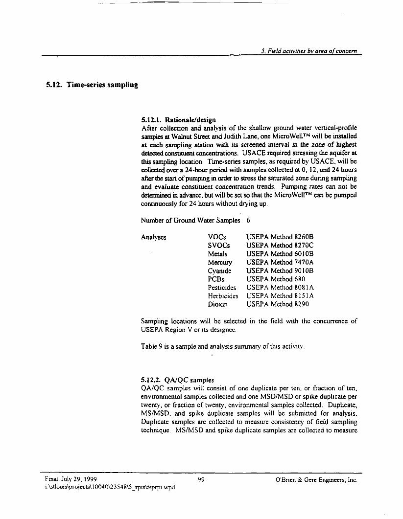
5. Field activities by area of concern
5.12. Time-series sampling
5.12.1. Rationale/designAfter collection and analysis of the shallow ground water vertical-profilesamples at Walnut Street and Judith Lane, one Micro Well™ will be installedat each sampling station with its screened interval in the zone of highestdetected constituent concentrations. US ACE required stressing the aquifer atthis sampling location. Time-series samples, as required by USAGE, will becollected over a 24-hour period with samples collected at 0, 12, and 24 hoursafter the start of pumping in order to stress the saturated zone during samplingand evaluate constituent concentration trends. Pumping rates can not bedetermined in advance, but will be set so that the Micro Well™ can be pumpedcontinuously for 24 hours without drying up.
Number of Ground Water Samples 6
Analyses VOCs USEPA Method 8260BSVOCs USEPA Method 8270CMetals USEPA Method 601 OBMercury USEPA Method 7470ACyanide USEPA Method 901 OBPCBs USEPA Method 680Pesticides USEPA Method 8081AHerbicides USEPA Method 8151ADioxm USEPA Method 8290
Sampling locations will be selected in the field with the concurrence ofUSEPA Region V or its designcc.
Table 9 is a sample and analysis summary of this activity.
5.12.2. QA/QC samplesQA/QC samples will consist of one duplicate per ten, or fraction of ten,environmental samples collected and one MSD/MSD or spike duplicate pertwenty, or fraction of twenty, environmental samples collected. Duplicate,MS/MSD, and spike duplicate samples will be submitted for analysis.Duplicate samples are collected to measure consistency of field samplingtechnique. MS/MSD and spike duplicate samples are collected to measure
Final July 29. 1999 99 O'Bnen & Cere Engineers, Inc.i:\stlouis\projects\10040\23548\5_rpts\fsprptvvpd
Field Sampling PlanSauget Area 1 Support Sampling PlanSauget and Canolda, IllinoisVolume 2A
laboratory quality control procedures. A field blank (or equipment blank)must be submitted to the laboratory with the investigative samples andanalyzed for the same parameters as the investigative samples. The minimumrequired is one per ten, or fraction of ten, environmental samples collected,unless dedicated or disposable sampling equipment is used to collect samples.A trip blank for VOC analysis will be included with each sample coolercontaining environmental samples for VOC analysis that is shipped.
5.12.3. Field proceduresMicroWells™ will be installed as described in section 5.9.3. Ground watersamples will be collected using polyethylene tubing, flexible tubing, and aperistaltic pump, as described in section 5.9.3. The samples will be collectedat the highest flow rate possible (approximately 3400 ml/min) with theperistaltic pump. Ground water samples will be collected when the pump isturned on (0 hr), 12 hours and 24 hours after initializing pumping.Conductivity, temperature, pH, and turbidity will be measured and recordedon the ground water sampling logs and in the field notebook. VOC containerswill be filled first, then the remaining containers. Collected samples will beplaced on ice in coolers, and chain-of-custody procedure will be initiated.After the 24-hr sample is collected, the MicroWell™ will be pulled, and thehole filled with bentonite.
5.12.4. DocumentationA field notebook will be kept for the MicroWell™ installation. At aminimum, the field notebook will include project name and number; date andtime; weather conditions; sampler's name; sample location; limiting fieldconditions; problems encountered; subcontractor personnel on-site; USEPARegion V personnel on-site; other personnel on-sile, and pH, conductivity,temperature, PID. explosimetcr, RAM. and turbidity measurements. Groundwater sampling logs with calibration values will also be completed. Notationof USEPA Region V acceptance or boring locations will be included in thefield notebook.
OBnen & Gere Engineers, Inc. 100 Final July 29, 1999i:\stlouis\projccts\10040\23548\5_rpts\fsprpt.wpd
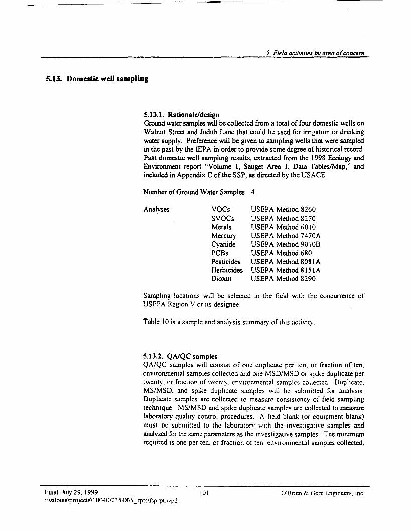
5. Field activities by area of concern
5.13. Domestic well sampling
5.13.1. Rationale/designGround water samples wilJ be collected from a total of four domestic wells onWalnut Street and Judith Lane that could be used for irrigation or drinkingwater supply. Preference will be given to sampling wells that were sampledin the past by the IEPA in order to provide some degree of historical record.Past domestic well sampling results, extracted from the 1998 Ecology andEnvironment report "Volume 1, Sauget Area 1, Data Tables/Map," andincluded in Appendix C of the SSP, as directed by the USAGE.
Number of Ground Water Samples 4
Analyses VOCs USEPA Method 8260SVOCs USEPA Method 8270Metals USEPA Method 6010Mercury USEPA Method 7470ACyanide USEPA Method 9010BPCBs USEPA Method 680Pesticides USEPA Method 8081AHerbicides USEPA Method 8151ADioxin USEPA Method 8290
Sampling locations will be selected in the field with the concurrence ofUSEPA Region V or its designee.
Table 10 is a sample and analysis summary of this activity
5.13.2. QA/QC samplesQA/QC samples will consist of one duplicate per ten, or fraction of ten,environmental samples collected and one MSD/MSD or spike duplicate pertwenty, or fraction of twenty, environmental samples collected. Duplicate,MS/MSD, and spike duplicate samples will be submitted for analysis.Duplicate samples are collected to measure consistency of field samplingtechnique MS/MSD and spike duplicate samples are collected to measurelaboratory quality control procedures A field blank (or equipment blank)must be submitted to the laboratory with the investigative samples andanalyzed for the same parameters as the investigative samples. The minimumrequired is one per ten, or fraction often, environmental samples collected.
Final July 29, 1999 101 O'Bnen &. Gere Engineers. Inci:\stlouis\projects\10040\23548\5_rpts\fsprpt\vpd
Field Sampling PlanSauget Area 1 Support Sampling PlanSauget and Cahokia, HJinobVolume 2A ______
unless dedicated or disposable sampling equipment is used to collect samples.A trip blank for VOC analysis will be included with each sample coolercontaining environmental samples for VOC analysis that is shipped.
5.13.3. Field proceduresAfter the well owners have been contacted and permission obtained in writingto collect well water samples, the well owners will be contacted by O'Brien &Gere to set a time for well sampling. The domestic well samples will becollected from a tap as close as possible to the well head. Availableinformation on well construction and pumps will be reviewed to evaluate thetime the water should be allowed to run prior to sample collection for systempurging. While the lines are purging, sample container labels can becompleted and affixed to the sample containers. After 10 minutes, pH,conductivity, temperature, and turbidity measurements will be obtained. Thenthe VOC container will be filled, followed by the remaining containers. Thesample containers will be placed on ice in a cooler, and cham-of-custodyprocedures initiated.
5.13.4. DocumentationA field notebook will be kept for the domestic well sampling. At a minimum,the field notebook will include project name and number, date and time,weather conditions, sampler's name, residence address, limiting fieldconditions, problems encountered, subcontractor personnel on-site, USEPARegion V personnel on-site, and other personnel on-site. Conductivity, pH,temperature, and turbidity measurements will also be recorded in the fieldnotebook. Notation of USEPA Region V acceptance of sampling locationswill be included in the field notebook.
OT3nen & Gere Engineers, inc. 102 Final July 29, 1999i:\stlouis\projecis\l0040\23548\5_rpis\fsprpt.wpd
5. Field activities by area of concern
5.14. Slug tests
5.14.1. Rationale/designA considerable amount of information on the hydraulic characteristics of theAmerican Bottoms aquifer is available from the Illinois Water Survey, IllinoisGeological Survey and US Geological Survey. Public information, augmentedby site-specific slug tests, may be all that is needed to design a pump and treatsystem should such a remedial measure be selected for a site. Performance ofa pumping test on a high yield aquifer creates practical problems such asstorage, treatment, and disposal of large volumes of pumped water. When itis necessary to design a pump and treat system, it may be simpler to use thebest available information to design the recovery and treatment system andthen add more recovery wells and treatment capacity if the system does notperform as expected. For these reasons, slug testing was selected as thepreferred method for evaluating site-specific aquifer hydraulic characteristics.
To conduct the slug tests, three 2-inch diameter, stainless steel piezometerswill be installed at each fill area (Sites G, H, I, L, and N) using the installationmethods described in section 5.3.3. The slug tests at each fill area will be usedto evaluate aquifer hydraulic conductivity. Slug tests will be conducted in theupper fine-grained zone, the middle fine sand zone, and the lower coarse sandzone typical of the American Bottoms aquifer in this area. These depths areestimated to be at 20,40, and 60 ft, respectively, below ground surface Thesedepths will be confirmed in the field from the waste characterization boringactivities.
Number of Slug Tests 15
5.14.2. QA/QC proceduresQA/QC procedures will consist of equipment test checks at each fill area andtwo repeat tests.
Final July 29, 1999 103 O'Bnen & Gcre Engineers, Inc.i:\stlouis\projects\10040\23548\5_rpts\fsprpt.wpd
Field Sampling PlanSauget Area 1 Support Sampling PlanSauget and Caholda, IllinoisVolume 2A
5.14.3. Field proceduresThis section presents the field protocols for the completion of in situ hydraulicconductivity tests.
Equipment requirements.• A pressure transducer connected to a data logger system• An inert solid slug of sufficient diameter and length to artificially raise or
lower the water level 1 ft or more in the well (commonly either a PVC orTeflon® slug)
• A timing device.
Test design.A. Identify the test objectives and document them.
B. Identify potential limitations of test and interpretation methods as theyrelate to the project and site.
C. Identify the available database for correlation purposes (other hydraulicconductivity test data, maps, or logs of subsurface soils).
D. Evaluate access to wells and obstructions or siltation in wells.
E. Review boring and well completion logs for wells to be tested for lithology,natural discontinuities, possible well yield, screen length, location ofground water table with respect to the screen interval, and type ofsand/gravel pack.
F. Identify the type of in situ hydraulic conductivity test to be used.
1. Only use a rising head test if the screened interval of the well straddlesthe water table. The introduction of water into the unsaturated portionof the formation during a falling head test will result in an inaccurateestimation of hydraulic conductivity.
2. If the screened interval of the well is fully submerged below the water,use both the rising or falling head test and average the results
G. Evaluate the amount of head change to be induced in the well
O'Bnen & Gere Engineers, Inc. 104 Final July 29, 1999i:\stlouis\projects\10040\23548\5_rpts\fsprpt.wpd
5. Field activities by area of concern
H. Evaluate the water level measurement frequency needed.
1. During the early portions of the test, measure water levels at closelyspaced intervals. The frequency of measurements will be governed bythe rate of recovery of the water level in the well. The faster therecovery, the more frequently the measurements need to be taken.Measurement frequency can decline logarithmically during the test (thelength of time between measurements increasing during the test).Water levels should be recorded until the water level has recovered to95% of static pre-test conditions.
I. Identify the type of slug and water level recording device to be used.
1. Choose the manual or electronic method based upon previouslycalculated hydraulic conductivity (K) values or expected K based upongrain size encountered within the well:
a. If K > 10'3 cm/sec, use pressure transducerb. If K < 10"3 cm/sec, use pressure transducer or manual method.
Field protocols.A. Record the following information in the project notebook and the slug test
field log in Appendix F:NameDateProject name and descriptionProject numberWeather conditionsWell number and well location in sufficient detail to relocate.
B. Measure and document static head If a pressure transducer is to be used,lower transducer into well, and secure the pressure transducer cable to thewell to prevent movement. Connect the pressure transducer to theelectronic data logger. Measure the static head with both the transducerand manually, then start the automatic recording by the data logger.
C. Insert the slug into or withdraw the slug from the ground water in the well.
1. Given the variability of test conditions, there is no absolute requirementfor the magnitude of the change in water level It is suggested that aminimum of 1 ft instantaneous hydraulic head change be created toallow for effective measurement of aquifer response About 75% of the
Final July 29, 1999 105 O'Bnen & Gcre Engineers, Inc.i :\stloui s\projects\ 10040X2 3 548\5_rpts\fsprpt wpd
Field Sampling PlanSauget Area 1 Support Sampling PlanSauget and Cahokia, DlinoiiVolume 2A
estimated displacement by the slug should be documented in the waterlevel recordings.
D. Measure the recovery of the water level in the well until 95% recovery tostatic conditions has been achieved.
1. For manual measurements, record the time (real or elapse time) and thedepth to ground water in the well in the project field book. Allmeasurements should be from the same point on the well casing usingthe same well probe.
2. For the pressure transducer, the time and water level will beautomatically recorded.
E. Data Review1. Make sure the necessary information is documented for each test within
the field notebook and on a slug test field log
2. Make a preliminary analysis of data before leaving the field to evaluateif test was successful:
a. Did the slug create an instantaneous head change in the well ofsufficient magnitude to observe a meaningful water level response?
b Did you collect a sufficient number of data points to define thewater level recovery for the test?
c. Is the test data generally consistent with your pre-tcst expectations'7
d. If the test was not successful, reevaluate the test design andcomplete a new test.
3 For electronic tests, copy the data file onto a disk and label the diskwith the project number, date, test well, and file name.
5.14.4. DocumentationA field notebook will be kept for the slug test evaluation At a minimum, thefield notebook will include project name and number, date and time, weather
O'Bnen & Gcre Engineers, Inc. 106 Final July 29, 1999i:\stlouis\projects\l0040\23548\5_rpts\fsprpt.wpd
5. Field activities by area of concern
conditions, tester's name, slug test location, limiting field conditions, problemsencountered, subcontractor personnel on-site, USEPA Region V personnel on-site, and other personnel on-site. Notation of USEPA Region V acceptance ofboring locations will be included in the field notebook. Slug test data will bedownloaded from the data logger each day. The data will be reviewed forerrors. If necessary, a slug test will be re-conducted.
5.15. Grain size analysis
5.15.1. Rationale/designOne soil boring will be completed adjacent to each fill area (Sites G, H, I, L,and N) to identify grain size of aquifer materials. Soil samples will becollected from the upper, middle, and lower aquifer zones (total of fifteensamples) using a Geoprobe™ or other suitable push technology. Samplelocations will be selected in the field with the concurrence of the USEPARegion V or its designee. Each soil sample will be analyzed for grain size.
Number of Grain Size Analyses 15
Table 11 is a sample and analysis summary of this activity.
5.15.2. QA7QC samplesAs this is a physical test, no QA/QC samples will be submitted.
5.15.3. Field procedureA large bore (MacroCorc®) soil sampler, using clear acetate liners, will behydraulically pushed to collect a soil sample at specified depths The collectedsample will be placed into labeled plastic, wide-mouth containers and scaled.The MacroCore® sampler will collect approximately 1300 mL of material,which is sufficient for grain size analysis. Should larger (large gravel tocobble) size materials be encountered, additional core samples will be obtainedand placed into additional containers Collected samples will be placed intoplastic coolers or corrugated boxes for shipment. Cham-of-custodyprocedures will be followed in order to track samples. The samples will be
Final July 29, 1999 107 O'Bnen & Gere Engineers, Inci:\stlouis\projects\10040\23548\5_rpts\fsprptwpd
Field Sampling PlanSauget Area 1 Support Sampling FlanSauget and Cahokia, niinoi*Volume 2A
submitted for grain size analysis using a sieve and hydrometer testing.Geoprobe™ holes will be filled with bentorute.
5.15.4. DocumentationA field notebook will be kept for the soil probing installation. At a minimum,the field notebook will include project name and number, date and time,weather conditions, sampler's name, sample location, limiting field conditions,problems encountered, subcontractor personnel on-site, USEPA Region Vpersonnel on-site, and other personnel on-site. Notation of USEPA Region Vacceptance of boring locations will be included in the field notebook.
5.16. Upgradient ground water sampling
5.16.1. Rationale/designExisting wells EE-20, EE-04, and EEC-108 will be used as background(upgradient) ground water sampling locations. These wells, which arescreened at depths of 23-28, 18-23, and 24-29 ft below ground surface,respectively, will be redeveloped as described in section 5.7. If these wellscannot be used, Geoprobe™, HydroPunch™, MicroWell™, WaterlooProfiler™, or equivalent sampling technology will be used to collect samplesfrom the center of the former screened intervals at each of these locationsusing low-flow sampling techniques. In addition, ground water samples willbe collected at depths of 60 and 100 ft below grade surface at each of theselocations using push sampling technologies such as Geoprobe™,HydroPunch™, MicroWell™, Waterloo Profiler™, or equivalent samplingtechnology and low-flow sampling techniques. A sampling depth of 60 ft isapproximately the midway between the screened interval of the existingshallow wells and the bottom of the aquifer, which is anticipated to beapproximately 100 ft deep.
Number of Ground Water Samples 9
CCBnen & Gere Engineers, Inc 108 Final July 29, 1999i:\stlouis\projects\10040\23548\5_rpts\fsprpt.wpd
5. Field activities by area of concern
Analyses VOCsSVOCsMetalsMercuryCyanidePCBsPesticidesHerbicidesDioxin
USEPA Method 8260USEPA Method 8270USEPA Method 60 10USEPA Method 7470AUSEPA Method 90 10BUSEPA Method 680USEPA Method 8 081 AUSEPA Method 8 151 AUSEPA Method 8290
Sampling locations will be selected in the field with the concurrence ofUSEPA Region V or its designee.
Table 12 is a sample and analysis summary of this activity
5.16.2. QA/QC samplesQA/QC samples will consist of one duplicate per ten, or fraction of ten,environmental samples collected and one MSD/MSD or spike duplicate pertwenty, or fraction of twenty, environmental samples collected. Duplicate,MS/MSD, and spike duplicate samples will be submitted for analysis.Duplicate samples are collected to measure consistency of field samplingtechnique. MS/MSD and spike duplicate samples are collected to measurelaboratory quality control procedures. A field blank (or equipment blank)must be submitted to the laboratory with the investigative samples andanalyzed for the same parameters as the investigative samples. The minimumrequired is one per ten, or fraction of ten, environmental samples collected,unless dedicated or disposable sampling equipment is used to collect samples.A trip blank for VOC analysis will be included with each sample coolercontaining environmental samples for VOC analysis that is shipped.
5.16.3. Field proceduresField procedures for collection of upgradient ground water samples will followthe procedures for well redevelopment and collection of ground water in thefills areas, described in section 5.7.3
Final July 29, 1999i:\stlouis\projects\10040\23548\5_rpts\fsprpt.wpd
109 O'Bnen & Gere Engineers, Inc.
Field Sampling PlanSauget Area 1 Support Sampling PlanSauget and Ganoid*, OlinoiiVolume 2A
5.16.4. DocumentationA field notebook will be kept for the upgradient ground water sampling. Ata minimum, the field notebook will include project name and number, date andtime, weather conditions, sampler's name, residence address, limiting fieldconditions, problems encountered, subcontractor personnel on-site, USEPARegion V personnel on-site, and other personnel on-site. Conductivity, pH,temperature, and turbidity measurements will also be recorded in the fieldnotebook. Notation of USEPA Region V acceptance of sampling locationswill be included in the field notebook.
5.17. Soil sampling
Soil samples will be collected in both undeveloped and developed areas thatare susceptible to flooding and deposition of wind-blown dust. Specifically,floodplain soil sampling will be conducted in an area bounded by QueenyRoad on the north, Falling Springs Road on the east, Illinois Route 157 on thesouth, and Illinois Route 3 (Mississippi Avenue) on the west. This is the areawhere water backs up at road crossings during heavy rains and where PCBsare known to occur in creek sediments. This area also includes most of theresidential development in Sauget Area 1.
Information from the soil sampling program \\ill be used to evaluate the extentof migration due to overbank flooding and wind-blown dust deposition. Inaddition, surficial and subsurface soil information will be used in the humanhealth risk assessment (construction/utility worker and residential exposurescenarios) The Human Health Risk Assessment Work Plan is in Volume IBof the SSP.
Floodplain soil samples will be collected every 200 ft on seven transects inundeveloped areas, a total of forty-five sampling stations. Based on thesesampling results, twenty soil sampling stations will be located in developedareas. Three samples will be collected in developed areas adjacent toTransects 1, 2, 3, 4, 5, and 6, and two samples will be collected in developedareas adjacent to Transect 7, which is the transect at the downgradient limit ofthe residential area. Twenty developed area samples are considered anappropriate number for identification in the SSP until undeveloped area soil
OBrien & Cere Engineers, Inc. 110 Final July 29, 1999i:\stlouis\projecls\10040V23548V5_rpts\fsprpt.wpd
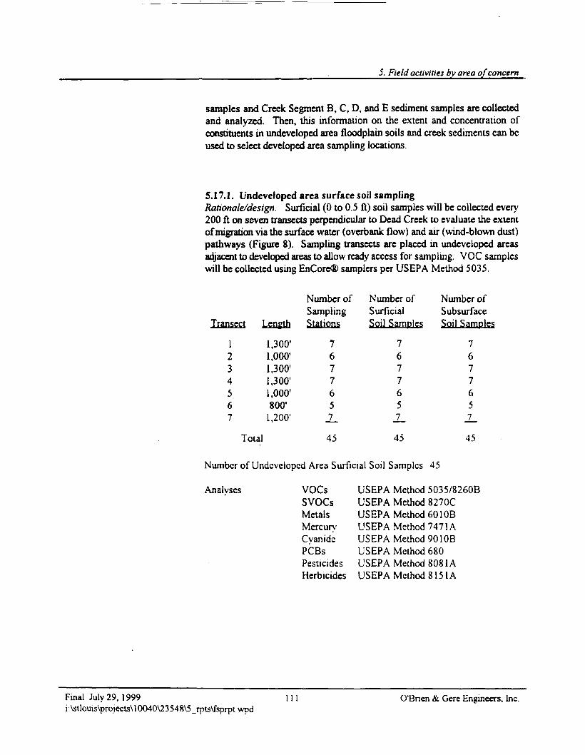
5. Field activities by area of concern
samples and Creek Segment B, C, D, and E sediment samples are collectedand analyzed. Then, this information on the extent and concentration ofconstituents in undeveloped area floodplain soils and creek sediments can beused to select developed area sampling locations.
5.17.1. Undeveloped area surface soil samplingRationale/design. Surficial (0 to 0.5 ft) soil samples will be collected every200 ft on seven transects perpendicular to Dead Creek to evaluate the extentof migration via the surface water (overbank flow) and air (wind-blown dust)pathways (Figure 8). Sampling transects are placed in undeveloped areasadjacent to developed areas to allow ready access for sampling. VOC sampleswill be collected using EnCore® samplers per USEPA Method 5035.
Transect
1234567
Length
1,300'1,000'1,300'1,300'1,000'800'1,200'
Number ofSamplingStations
7677651_
Number ofSurficialSoil Samples
7677651_
Number ofSubsurfaceSoil Samples
7677657
Total 45 45 45
Number of Undeveloped Area Surficial Soil Samples 45
Analyses VOCs USEPA Method 5035/8260BSVOCs USEPA Method 8270CMetals USEPA Method 601 OBMercury USEPA Method 7471ACyanide USEPA Method 901 OBPCBs USEPA Method 680Pesticides USEPA Method 8081AHerbicides USEPA Method 8151A
Final July 29. 1999i:\stlouis\projects\10040\23548\5_rpts\fsprpt\vpd
11 O'Bnen & Gerc Engineers, Inc.
Field Sampling PlanSauget Area 1 Support Sampling PlanSauget and Cahokia, DUnouVolume 2A
Sampling locations will be selected in the field with the concurrence ofUSEPA Region V or its designee.
Table 13 is a sample and analysis summary of this activity.
5.17.2. Undeveloped area subsurface soil samplingRationale/design. Subsurface (0.5 to 6 ft) soil samples will be collectedevery 200 ft on seven transects perpendicular to Dead Creek to evaluate theextent of migration via the surface water (ovcrbank flow) and air (wind-blowndust) pathways (Figure 8). Subsurface soil samples will be collected from 0.5ft to 6 ft below ground surface. Visual observation (discoloration) and fieldPID readings will be used to identify the most impacted portion of the sample.This section will be selected for chemical analysis. Surface and subsurfacesoil sampling stations will be co-located. VOC samples will be collected usingEnCorc® samplers per USEPA Method 5035
Number of Undeveloped Area Subsurface Soil Samples 45
Analyses VOCs USEPA Method 5035/8260BMethod 8270CMethod 601 OBMethod 7471AMethod 901 OBMethod 680Method 8081AMethod 8151A
Sampling locations will be selected in the field with the concurrence ofUSEPA Region V or its designee.
Table 14 is a sample and analysis summary of this activity
VOCsSVOCsMetalsMercuryCvanidePCBsPesticidesHerbicides
USEPAUSEPAUSEPAUSEPAUSEPAUSEPAUSEPAUSEPA
5.17.3. Undeveloped area soil dioxin samplingRationale/design. As directed by USAGE, 20% of the surface soil sampleswill be analy/cd for dioxin To provide information for the human health nskassessment (construcuon/utility worker exposure;, USEPA Region V directed
O'Bnen & Gere Engineers, Inc. 112 Final July 29, 1999i:\stlouis\projects\10040\23548\5_rpts\fsprpt.wpd
5. Field activities by area of concent
that 20% of the subsurface soil samples will be analyzed for dioxin. Visualobservation (discoloration) and field PID readings will be used to identify themost impacted portion of the sample. This section will be selected forchemical analysis.
Number of Undeveloped Area Surface Soil Dixoin Samples 9Number of Undeveloped Area Subsurface Soil Dioxin Samples 9
Analyses Dioxin USEPA Method 8280
Sampling locations will be selected in the field with the concurrence ofUSEPA Region V or its designee.
Tables 13 and 14 are sample and analysis summaries of this activity.
5.17.4. QA/QC samplesQA/QC samples will consist of one duplicate per ten. or fraction of ten,environmental samples collected and one MSD/MSD or spike duplicate pertwenty, or fraction of twenty, environmental samples collected. Duplicate,MS/MSD, and spike duplicate samples will be submitted for analysis.Duplicate samples are collected to measure consistency of field samplingtechnique. MS/MSD and spike duplicate samples are collected to measurelaboratory quality control procedures. A field blank (or equipment blank)must be submitted to the laboratory with the investigative samples andanalyzed for the same parameters as the investigative samples The minimumrequired is one per ten, or fraction of ten, environmental samples collected,unless dedicated or disposable sampling equipment is used to collect samples.A trip blank for VOC analysis will be included with each sample coolercontaining environmental samples for VOC analysis that is shipped.
5.17.5. Field proceduresSurficial sampling At the outset of surface soil sampling, follow theseinstructions. Surface soil samples will be discrete:
Discrete sample represents a single location in the soil column This type ofsample is also used for discrete analysis of surface soil conditions.Discrete soil samples are collected from near surface soils at locationsidentified in a work plan. Hand augers, disposable scoops, hand trowels,or shovels arc used to collect these samples
Final July 29, 1999 113 O'Bnen & Gerc Engineers, Inc.i:\stlouis\projects\10040\23548\5_rpts\fsprpt.wpd
Field Sampling PlanSauget Area 1 Support Sampling PlanSauget and Cabokia, IllinoisVolume 2A
Use the following procedure to collect a sample:
1. If necessary, penetrate the soil to the appropriate sampling depth.
2. Using a clean tool, remove and discard a thin layer of soil from the area.Record the characteristics of the soils including grain size, content,staining, and color.
3. To collect a discrete soil sample for VOC analysis, a 5-gram EnCore®sampler will be used. After pressing the sampler into the soil at thesampling location, cap the coring body while it is still in the EnCore®sampler T-handle. To collect a discrete soil sample for other parameters,use a stainless steel laboratory spoon or equivalent. Homogenize the non-VOC samples as necessary.
4. Place the homogenized sample into appropriate sample containers. Inaddition to analytical samples, a reference sample consideredrepresentative of the soil may also be collected in a wide mouth jar andstored for possible future physical analyses such as grain size analysis.
5. Check that the cap of each sample container has a Teflon® liner, ifrequired for the analytical method. Secure the cap tightly.
6. Label the sample container with the appropriate sample tag. The tagscould be permanent labels or clean tape Label the tag carefully and clearlyusing indelible ink. Complete appropriate sampling forms and record inthe field notebook. Pre-labeled containers are handy, particularly if you arewearing gloves or if the weather is inclement.
7. Initiate the chain-of-custody form.
8. Place the capped EnCore® sampler core bodies and other samplecontainers on ice in a cooler to maintain the samples at approximately 4°C.Ship the cooler to the laboratory for analysis within 48 hr of samplecollection
9 Decontaminate equipment between sample locations and after use asdescribed in section 573
OBnen & Gere Engineers, Inc. 14 Final July 29, 1999i:\stlouis\projectsU0040\23548\5_rpts\fsprpt.wpd
5. Field activities by area of concern
Subsurface sampling. A steel hand auger will be used to collect soil samplesat a depth of 0.5 to 6 ft below existing grade. Soil samples will be collectedby placing a 4 ft by 4 ft piece of plastic sheeting on the ground over thelocation where the surface soil sample was collected. A hole will be cut in theplastic sheeting for insertion of the hand auger. The hand auger will then beused to make a borehole in the soil. Soil between the surface and 3 ft belowexisting grade will be placed on the plastic sheeting. Upon reaching a depthof 3 ft below existing grade, collected soil samples will be placed into labeled,laboratory-supplied, clean sample containers. A 5-gram EnCore® samplerwill be used to collect VOC samples from the subsurface. After collection ofsoil in the hand auger and before homogenization, the EnCore® sampler willbe used to collect a VOC sample from the hand auger. Filled, labeled andcapped EnCore® sampler core bodies and sample containers will be placed onice in a cooler. Chain-of-custody procedures will be followed. The boreholewill be filled with bentonite. The surface (top 2 ft) will be restored with soiland seeded. Boring-generated soils will be contained and transported to thecentrally located solid waste disposal container. General waste will becontained in plastic bags and disposed of in a general refuse container.
Should hand augenng prove impractical, a direct push technology will be usedto collect the soil sample. The soil sample will be collected using theMacroCore® sampler. The MacroCore® sampler will have a clear acetateliner. The push sample will be collected from 3 to 6 ft below grade. A VOCsample will be collected from the top portion of the sample using a 5-gramEnCore® sampler. The remaining portion will be homogenized in a stainlesssteel bowl and used to fill the remaining sample containers The collectedsamples will be placed on ice in a cooler, and chain-of-custody procedures willbe followed. The boreholes will be filled with bentonite A PID, anexplosimeter, and a RAM will be used on a continuous basis to monitor theseactivities.
5.17.6. DocumentationA field notebook will be kept for the soil bonng installation At a minimum,the field notebook will include the project name and number; date and time;weather conditions; sampler's name, sample location; depth of bonng, PID,explosimeter, and RAM readings; limiting field conditions; problemsencountered; subcontractor personnel on-site; USEPA Region V personnel on-site; and other personnel on-site. Notation of USEPA Region V acceptanceof bonng locations will be included in the field notebook.
Final July 29, 1999 115 O'Bnen & Gere Engineers, Inc.i:\stlouis\projects\10040\23548\5_rpts\fsprptvvpd
Field Sampling PlanSauget Area 1 Support Sampling PlanSauget and Cabolda, OlinouVolume 2A
5.18. Soil sampling, developed areas
5.18.1. Developed area surface soil samplingRationale/design. Surficial soil samples (0 to 0.5 ft below ground surface)will be collected in at least twenty locations in developed areas. Soil sampleswill be collected at three residences adjacent to Transects 1 to 6 and at tworesidences adjacent to Transect 7.
Number of Developed Area Surface Soil Samples 20
Analyses VOCs USEPA Method 5035/8260BSVOCs USEPA Method 8270CMetals USEPA Method 601 OBMercury USEPA Method 7471ACyanide USEPA Method 901 OBPCBs USEPA Method 680Pesticides USEPA Method 8081AHerbicides USEPA Method 8151A
Sampling locations will be selected in the field with the concurrence ofUSEPA Region V or its designee.
Table 15 is a sample and analysis summary of this activity.
5.18.2. Developed area subsurface soil samplingRationale/design. Subsurface soil samples (0.5 to 6 ft below ground surface)will be collected in at least twenty locations in developed areas. Soil sampleswill be collected at three residences adjacent to Transects 1 to 6 and at tworesidences adjacent to Transect 7 Visual observation (discoloration) and fieldPID readings will be used to identify the most impacted portion of the sample.This section will be selected for chemical analysis. VOC samples will becollected using EnCore® samplers per USEPA Method 5035
Number of Developed Area Subsurface Soil Samples 20
O'Bnen & Gere Engineers, Inc. 116 Final July 29, 1999i:\stlouis\projecis\l0040\23548\5_rpts\fsprpt.wpd
5. Field activities by area of concern
Analyses VOCs USEPA Method 5035/8260BSVOCs USEPA Method 8270CMetals USEPA Method 601 OBMercury USEPA Method 7471ACyanide USEPA Method 901 OBPCBs USEPA Method 680Pesticides USEPA Method 8081AHerbicides USEPA Method 8151A
Sampling locations will be selected in the field with the concurrence ofUSEPA Region V or its designee.
Table 16 is a sample and analysis summary of this activity.
5.18J. Developed area soil dioxin samplingRationale/design. Ad directed by USAGE, 20% of the surface soil sampleswill be analyzed for dioxin. To provide information for the human health riskassessment (construction/utility worker exposure), USEPA Region V directedthat 20% of the subsurface soil samples will be analyzed for dioxin. Visualobservation (discoloration) and field PID readings will be used to identity themost impacted portion of the sample. This section will be selected forchemical analysis.
Number of Developed Area Surface Soil Dixoin Samples 4Number of Developed Area Subsurface Soil Dioxin Samples 4
Analyses Dioxin USEPA Method 8280
Sampling locations will be selected in the field with the concurrence ofUSEPA Region V or its designee
Tables 15 and 16 are sample and analysis summaries of this activity.
5.18.4. QA/QC samplesQA/QC samples will consist of one duplicate per ten, or fraction of ten,environmental samples collected and one MSD/MSD or spike duplicate pertwenty, or fraction of twenty, environmental samples collected Duplicate,MS/MSD, and spike duplicate samples will be submitted for analysis.Duplicate samples arc collected to measure consistency of field sampling
Final July 29, 1999 117 O'Bnen & Gere Engineers, Inc.i :\stlouis\projects\ 10040X23 548\5_rpts\fsprpt. wpd
Field Sampling PlanSauget Area 1 Support Sampling PlanSauget and Cahokia, niinoUVolume 2A
technique. MS/MSD and spike duplicate samples are collected to measurelaboratory quality control procedures. A field blank (or equipment blank)must be submitted to the laboratory with the investigative samples andanalyzed for the same parameters as the investigative samples. The minimumrequired is one per ten, or fraction of ten, environmental samples collected,unless dedicated or disposable sampling equipment is used to collect samples.A trip blank for VOC analysis will be included with each sample coolercontaining environmental samples for VOC analysis that is shipped.
5.18.5. Field proceduresField procedures for collection of surface and subsurface soil samples indeveloped areas will follow the procedures for collection of surface andsubsurface soil samples in undeveloped areas as described in section 5.17.5.
5.18.6. DocumentationA field notebook will be kept for surface and subsurface soil sampling. At aminimum, the field notebook will include the project name and number; dateand time; weather conditions; sampler's name; sample location; depth ofboring; PID, explosimeter, and RAM readings; limiting field conditions;problems encountered; subcontractor personnel on-site; USEPA Region Vpersonnel on-site; and other personnel on-site. Notation of USEPA Region Vacceptance of surface and subsurface soil sampling locations will be includedin the field notebook.
5.19. Background soil samples
5.19.1. Rationale/designBackground soil samples will be collected at the locations of the backgroundground water wells, specifically existing wells EE-20, EE-04 and EEG-108which are east of Sites I, H, and L, respectively Samples will be collected
OBnen & Gere Engineers, Inc. 118 Final July 29, 1999i : \stlouis\projccts\ 10040V23 548V5_rpts\fsprpt. wpd
5. Field activities by area of concern
from depths of 0 to 0.5 ft and 0.5 to 6 ft below ground surface. Visualobservation (discoloration) and PID readings will be used to identify the mostimpacted portion of the sample for analysis. VOC samples will be collectedusing EnCore® samplers per USEPA Method 5035.
Number of Background Soil Samples 6
Analyses VOCs USEPA Method 5035/8260BSVOCs USEPA Method 8270CMetals USEPA Method 601 OBMercury USEPA Method 7471ACyanide USEPA Method 901 OBPCBs USEPA Method 680Pesticides USEPA Method 8081AHerbicides USEPA Method 8151ADioxin USEPA Method 8280
Sampling locations will be selected in the field with the concurrence ofUSEPA Region V or its designee.
Table 17 is a sample and analysis summary of this activity
5.19.2. QA/QC samplesQA/QC samples will consist of one duplicate per ten, or fraction of ten,environmental samples collected and one MSD/MSD or spike duplicate pertwenty, or fraction of twenty, environmental samples collected. Duplicate,MS/MSD, and spike duplicate samples will be submitted for analysis.Duplicate samples are collected to measure consistency of field samplingtechnique. MS/MSD and spike duplicate samples arc collected to measurelaboratory quality control procedures. A field blank (or equipment blank)must be submitted to the laboratory with the investigative samples andanalyzed for the same parameters as the investigative samples. The minimumrequired is one per ten, or fraction often, environmental samples collected,unless dedicated or disposable sampling equipment is used lo collect samples.A trip blank for VOC analysis will be included with each sample coolercontaining environmental samples for VOC analysis that is shipped.
Final July 29, 1999 119 O'Bnen & Cere Engineers, Inc.i:\stlouis\projects\10040\23548\5_rpts\fsprptwpd
Field Sampling PlanSauget Area 1 Support Sampling PlanSauget and Cahoida, DlinobVolume 2A
5.193. Field proceduresField procedures for collection of background soil samples will follow theprocedures for collection of soil samples in the undeveloped areas, describedin section 5.17.5.
5.19.4. DocumentationA field notebook will be kept for background soil sampling. At a minimum,the field notebook will include the project name and number; date and time;weather conditions; sampler's name; sample location; depth of boring; PID,explosimeter, and RAM readings; limiting field conditions; problemsencountered; subcontractor personnel on-site; USEPA Region V personnel on-site; and other personnel on-site. Notation of USEPA Region V acceptanceof background soil sampling locations will be included in the field notebook.
5.20. Sediment sampling
Vertically integrated sediment samples will be collected in Dead Creek toevaluate the extent of downstream migration of site-related constituents andto provide information for use in the human health nsk assessment(recreational teenage and recreational fishing scenarios) and the ecological riskassessment (endpoint organism exposure to sediments). The Human HealthRisk Assessment Work Plan is in Volume IB of the SSP, and the EcologicalRisk Assessment Work Plan is in Volume 1C. It should be noted thatsediment samples will be collected beginning at the most downgradientlocation and after collection of surface water samples. Given the 17,000-ftlength of Dead Creek, sediment sampling at 400-ft intervals will providesufficient information to evaluate the extent of downstream migration ofindustry-specific constituents. As directed by USEPA Region V, sedimentsamples will be collected at 200-ft intervals in the undeveloped portions ofDead Creek (i.e., Creek Segments B and F) and at 150-ft intervals in thedeveloped portions of Dead Creek, specifically Creek Segments C, D, and E,to evaluate the extent of migration of industry-specific constituents. A 150-ftsediment sampling interval was used in the 1991 Geraghty & Millerinvestigation of Creek Segment B; therefore, repeating sample collection at a
OTBrien & Gere Engineers, Inc. 120 Final July 29, 1999i:\stlouis\projects\ 10040Y23 548\5_rpts\fsprpt.wpd
5. Field activities by area of concern
150-ft interval is not considered appropriate in this creek segment even thoughits southern end passes through a developed area. For this reason, sedimentsamples will be collected at 200-ft intervals in Creek Segment B. Sedimentsamples will be collected every 1000 ft in Dead Creek to evaluate the extentof migration of site-related constituents.
As directed by USACE, sediment sampling locations in Creek Segments B, C,D, E, and the portion of Creek Segment F upstream of Borrow Pit Lake willbe adjusted in the field so that samples are obtained at the upstream anddownstream ends of each road culvert at a specified radial distance from theculvert. Samples will be collected within a radial distance of 10 ft from theupstream and downstream end of each road culvert.
The extent of migration information collected as part of this task, coupled withsediment thickness measurements and channel cross-sectional area, willprovide enough information to evaluate the volume of impacted sediments.
Sediment samples will not be collected in Creek Segment A. This creeksegment was used as a storm water detention basin which was dredged anumber of times to remove accumulated sediment. Dredge spoil was placedon the creek banks and Site I. Cerro Copper performed an lEPA-approvedremedial action for Creek Segment A in 1990 and 1991. Approximately20,000 yd3 of impacted sediments were excavated from depths of 10 to 15 ftbelow grade and transported off site for disposal at the Waste Managementlandfill in Emelle, Alabama. After excavation, an HOPE vapor barrier wasinstalled, and Creek Segment A was backfilled. The site is now fenced andused as a controllcd-access truck parking lot Since Creek Segment A wasremediated under an agreement with IEPA, no further characterization isconsidered necessary.
5.20.1. Undeveloped area sediment samplingRationale/design. Vertically integrated sediment core samples will becollected at 200-ft intervals in Creek Segment B and Creek Segment F toevaluate the extent of downstream migration of constituents related to specificindustrial sources located at the upstream end of Dead Creek (Figure 9). Thecombined length of these creek segments is approximately 10,000 ft.Industry-specific constituents include PCBs (discontinued chemicalmanufacturing operation), total petroleum hydrocarbons (TPH) (closed oilrefinery), copper (active metal refining), and zinc (active metal refining) Thisinformation will also be used in the human health risk assessment.
Final July 29, 1999 121 O'Bnen & Gere Engineers, Inc.i:\stlouis\projects\10040\23548\5_rpts\fsprptwpd
Field Sampling PlanSauget Ana 1 Support Sampling PlanSauget and Cahokia, DlinoitVolume 2A
Samples will be collected in depositional areas at the thickest sediment profile.Channel cross-section will be surveyed at each sampling station, and sedimentdepth will be measured at three locations perpendicular to the channel (channelcenter, halfway between channel center and right channel edge, and halfwaybetween channel center and left channel edge).
Number of Sediment Samples
Analyses PCBsTPHCopperZincTOCGrain SizeSolids Content
50
USEPA Method 680USEPA Method 8015BUSEPA Method 7211USEPA Method 7951USEPA Method 9060Physical MethodUSEPA Method SM2540G
Savannah Laboratories, which will perform the sediment analyses, does nothave a procedure in their QAPP for analyzing zinc by AA. SavannahLaboratories has all the necessary equipment to conduct this analysis, but doesnot have the necessary lamp. This lamp will be purchased prior to the start ofsample collection.
Sampling locations will be selected in the field with the concurrence ofUSEPA Region V or its designee.
Table 18 is a sample and analysis summary of this activity.
QA/QC samples. QA/QC samples will consist of one duplicate per ten, orfraction often, environmental samples collected and one MS/MSD or spikeduplicate per twenty, or fraction of twenty, environmental samples collected.Duplicate, MS/MSD, and spike duplicate samples will be submitted foranalysis. Duplicate samples are collected to measure consistency of fieldsampling technique. MS/MSD and spike duplicate samples are collected tomeasure laboratory quality control procedures. A field blank (or equipmentblank) must be submitted to the laboratory with the investigative samples andanalyzed for the same parameters as the investigative samples The minimum
OBrien & Gere Engineers, Inc. 122 Final July 29, 1999i : \stlouis\projects\ 10040\23548\5_rpts\fsprpt.wpd
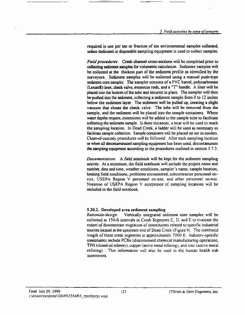
5. Field activities by area of concern
required is one per ten or fraction of ten environmental samples collected,unless dedicated or disposable sampling equipment is used to collect samples.
Field procedures. Creek channel cross-sections will be completed prior tocollecting sediment samples for volumetric calculation. Sediment samples willbe collected at the thickest part of the sediment profile as identified by thesurveyors. Sediment samples will be collected using a manual push-typesediment core sampler. The sampler consists of a P VC barrel, polycarbonate(Lexan®) liner, check valve, extension rods, and a "T" handle. A liner will beplaced into the bottom of the tube and secured in place. The sampler will thenbe pushed into the sediment, collecting a sediment sample from 0 to 12 inchesbelow the sediment layer. The sediment will be pulled up, creating a slightvacuum that closes the check valve. The tube will be removed from thesample, and the sediment will be placed into the sample containers. Wherewater depths require, extensions will be added to the sample tube to facilitatecollecting the sediment sample. In these instances, a boat will be used to reachthe sampling location. In Dead Creek, a ladder will be used as necessary tofacilitate sample collection. Sample containers will be placed on ice in coolers.Chain-of-custody procedures will be followed. After each sampling locationor when all decontaminated sampling equipment has been used, decontaminatethe sampling equipment according to the procedures outlined in section 5.7.3.
Documentation. A field notebook will be kept for the sediment samplingactivity. At a minimum, the field notebook will include the project name andnumber, date and time, weather conditions, sampler's name, sample location,limiting field conditions, problems encountered, subcontractor personnel on-site, USEPA Region V personnel on-sitc. and other personnel on-site.Notation of USEPA Region V acceptance of sampling locations will beincluded in the field notebook.
5.20.2. Developed area sediment samplingRationale/design. Vertically integrated sediment core samples will becollected at 150-ft intervals in Creek Segments C, D, and E to evaluate theextent of downstream migration of constituents related to specific industrialsources located at the upstream end of Dead Creek (Figure 9) The combinedlength of these creek segments is approximately 7000 ft Industry-specificconstituents include PCBs (discontinued chemical manufacturing operation),TPH (closed oil refinery), copper (active metal refining), and zinc (active metalrefining). This information will also be used in the human health nskassessment
Final July 29, 1999 123 O'Bnen & Gcre Engineers, Inc.i:\stlouis\projects\10040\23548\5_rpls\fsprpt\vpd
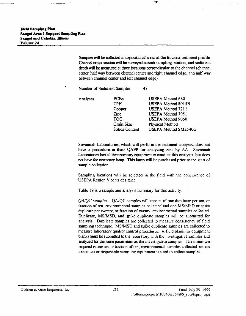
Field Sampling PlanSauget Area 1 Support Sampling PlanSauget and Cahokia, DlinoiiVolume 2A
Samples wilJ be collected in depositional areas at the thickest sediment profile.Channel cross-section will be surveyed at each sampling station, and sedimentdepth will be measured at three locations perpendicular to the channel (channelcenter, halfway between channel center and right channel edge, and half waybetween channel center and left channel edge).
Number of Sediment Samples 47
Analyses PCBsTPHCopperZincTOCGrain Size
USEPA Method 680USEPA Method 8015BUSEPA Method 7211USEPA Method 7951USEPA Method 9060Physical Method
Solids Content USEPA Method SM2540G
Savannah Laboratones, which will perform the sediment analyses, does nothave a procedure in their QAPP for analyzing zinc by AA. SavannahLaboratories has all the necessary equipment to conduct this analysis, but doesnot have the necessary lamp. This lamp will be purchased prior to the start ofsample collection.
Sampling locations will be selected in the field with the concurrence ofUSEPA Region V or its designec
Table 19 is a sample and analysis summary for this activity
QA/QC samples. QA/QC samples will consist of one duplicate per ten, orfraction of ten, environmental samples collected and one MS/MSD or spikeduplicate per twenty, or fraction of twenty, environmental samples collected.Duplicate, MS/MSD, and spike duplicate samples will be submitted foranalysis. Duplicate samples are collected to measure consistency of fieldsampling technique. MS/MSD and spike duplicate samples are collected tomeasure laboratory quality control procedures. A field blank (or equipmentblank) must be submitted to the laboratory with the investigative samples andanalyzed for the same parameters as the investigative samples. The minimumrequired is one ten. or fraction often, environmental samples collected, unlessdedicated or disposable sampling equipment is used to collect samples.
O'Bnen & Gere Engineers, Inc 124 Final July 29, 1999i:\stlouis\projects\l0040\23548\5_rpts\fsprpt.wpd
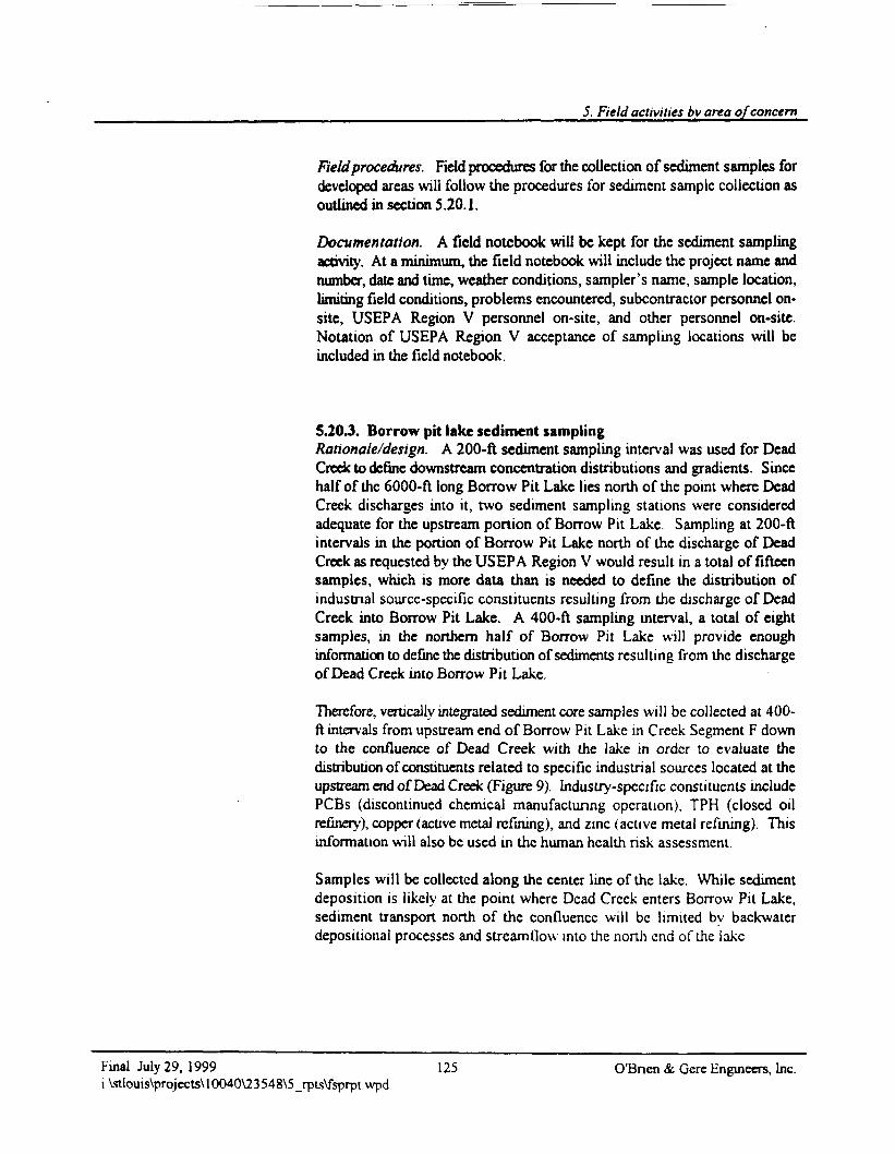
5. Field activities by area of concern
Field procedures. Field procedures for the collection of sediment samples fordeveloped areas will follow the procedures for sediment sample collection asoutlined in section 5.20.1.
Documentation. A field notebook will be kept for the sediment samplingactivity. At a minimum, the field notebook will include the project name andnumber, date and time, weather conditions, sampler's name, sample location,limiting field conditions, problems encountered, subcontractor personnel on-site, USEPA Region V personnel on-site, and other personnel on-site.Notation of USEPA Region V acceptance of sampling locations will beincluded in the field notebook.
5.20 J. Borrow pit lake sediment samplingRationale/design. A 200-ft sediment sampling interval was used for DeadCreek to define downstream concentration distributions and gradients. Sincehalf of the 6000-ft long Borrow Pit Lake lies north of the point where DeadCreek discharges into it, two sediment sampling stations were consideredadequate for the upstream portion of Borrow Pit Lake. Sampling at 200-ftintervals in the portion of Borrow Pit Lake north of the discharge of DeadCreek as requested by the USEPA Region V would result in a total of fifteensamples, which is more data than is needed to define the distribution ofindustrial source-specific constituents resulting from the discharge of DeadCreek into Borrow Pit Lake. A 400-ft sampling interval, a total of eightsamples, in the northern half of Borrow Pit Lake will provide enoughinformation to define the distribution of sediments resulting from the dischargeof Dead Creek into Borrow Pit Lake.
Therefore, vertically integrated sediment core samples will be collected at 400-ft intervals from upstream end of Borrow Pit Lake in Creek Segment F downto the confluence of Dead Creek with the lake in order to evaluate thedistribution of constituents related to specific industrial sources located at theupstream end of Dead Creek (Figure 9). Industry-specific constituents includePCBs (discontinued chemical manufacturing operation), TPH (closed oilrefinery), copper (active metal refining), and zinc (active metal refining). Thisinformation will also be used in the human health risk assessment.
Samples will be collected along the center line of the lake. While sedimentdeposition is likely at the point where Dead Creek enters Borrow Pit Lake,sediment transport north of the confluence will be limited by backwaterdepositional processes and streamflow into the north end of the lake
Final July 29, 1999 125 O'Bnen & Gere Engineers, Inc.i:\stlouis\projects\10040\23548\5_rpts\fsprptwpd
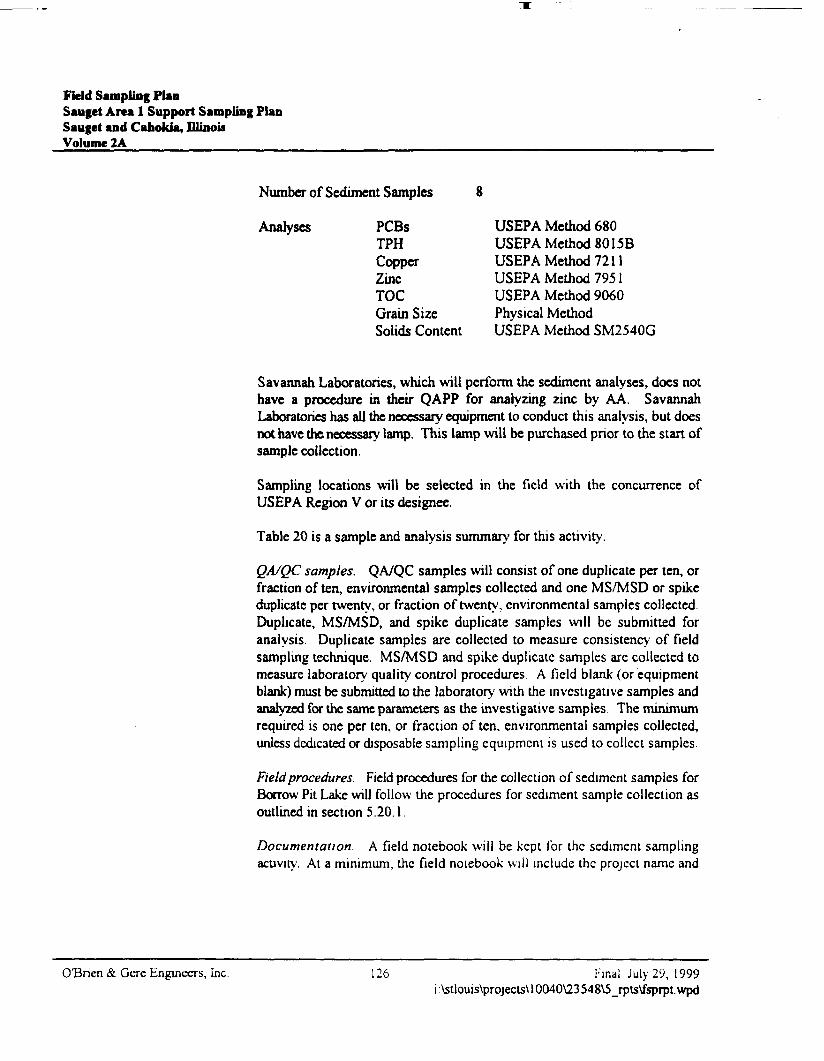
Field Sampling PlanSauget Area 1 Support Sampling PlanSauget and Cahokia, IllinoisVolume 2A
Number of Sediment Samples
Analyses PCBsTPHCopperZincTOCGrain Size
USEPA Method 680USEPA Method 8015BUSEPA Method 7211USEPA Method 7951USEPA Method 9060Physical Method
Solids Content USEPA Method SM2540G
Savannah Laboratories, which will perform the sediment analyses, does nothave a procedure in their QAPP for analyzing zinc by AA. SavannahLaboratories has all the necessary equipment to conduct this analysis, but doesnot have the necessary lamp. This lamp will be purchased prior to the stan ofsample collection.
Sampling locations will be selected in the field with the concurrence ofUSEPA Region V or its designee.
Table 20 is a sample and analysis summary for this activity.
QA/QC samples. QA/QC samples will consist of one duplicate per ten, orfraction often, environmental samples collected and one MS/MSD or spikeduplicate per twenty, or fraction of twenty, environmental samples collectedDuplicate, MS/MSD, and spike duplicate samples will be submitted foranalysis. Duplicate samples are collected to measure consistency of fieldsampling technique. MS/MSD and spike duplicate samples are collected tomeasure laboratory quality control procedures A field blank (or equipmentblank) must be submitted to the laboratory with the investigative samples andanalyzed for the same parameters as the investigative samples The minimumrequired is one per ten, or fraction of ten, environmental samples collected,unless dedicated or disposable sampling equipment is used to collect samples.
Field procedures. Field procedures for the collection of sediment samples forBorrow Pit Lake will follow the procedures for sediment sample collection asoutlined in section 5.20.1
Documentation. A field notebook will be kept for the sediment samplingacuvity. At a minimum, the field notebook will include the project name and
0"Bnen & Gere Engineers, Inc. 126 Final July 29, 1999i:\stlouis\projects\ 10040\23548\5_rpts\fsprpt.wpd
5. Field activities by area of concern
number, date and time, weather conditions, sampler's name, sample location,limiting field conditions, problems encountered, subcontractor personnel on-site, USEPA Region V personnel on-site, and other personnel on-site.Notation of USEPA Region V acceptance of sampling locations will beincluded in the field notebook.
5.20.4. Dead Creek sediment samplingRationale/design. Vertically integrated sediment core samples will becollected every 1000 ft in Dead Creek, from the upstream end of CreekSegment B to the downstream end of Creek Segment F at the Old Praihe duPont Creek lift station, to evaluate the extent of downstream migration oftarget compound list/target analyte list (TCL/TAL) constituents (Figure 10).These broad-scan analyses are also intended to provide information for thehuman health risk assessment.
Two sediment core samples will be collected in Borrow Pit Lake in CreekSegment F upstream of the discharge of Dead Creek to assess the effect ofbackwater conditions and/or the contributions of other sources. One samplewill be collected upstream, and one sample will be collected downstream of theconfluence of Dead Creek and Old Praihe du Pont Creek to evaluate theimpact of the Dead Creek discharge on sediment quality in Old Praihe du PontCreek.
The location of the upstream sample in Old Prainc du Pont Creek will becollected at an appropriate distance from the confluence with Dead Creek sothat possible previous effects of flooding and flow reversals will not affect thecollection of the background sample. As reported in the 1996 HRS packageprepared by PRC Environmental Management, Inc. for USEPA Region V, abackground sampling station was located 200 ft north of the confluence ofDead Creek and Old Praihe du Pont Creek. The sediment background samplewill be collected at this location.
Samples will be collected in depositionaJ areas at the thickest sediment profileChannel cross-section will be surveyed at each sampling station and sedimentdepth will be measured at three locations perpendicular to the channel (channelcenter, halfway between channel center and nght channel edge, and halfwaybetween channel center and left channel edge).
Final July 29. 1999 127 O'Bnen & Gere Engineers, Inci:\stlouis\projects\10040\23548\5_rptsVfsprptwpd
Field Sampling PlanSauget Area 1 Support Sampling PlanSauget and Cahokia, IllinoisVolume 2A
Number of Sediment Samples
Analyses
20
VOCsSVOCsMetalsMercuryCyanidePCBsPesticidesHerbicidesDioxinTOCGrain SizeSolids Content
USEPA Method 5035/8260BUSEPA Method 8270CUSEPA Method 601 OBUSEPA Method 7471 AUSEPA Method 901 OBUSEPA Method 680USEPA Method 8081 AUSEPA Method 8 151 AUSEPA Method 8290USEPA Method 9060Physical MethodUSEPA Method SM2540G
Sampling locations will be selected in the field with the concurrence ofUSEPA Region V or its designce.
Table 21 is a sample and analysis summary for this activity.
QA/QC samples. QA/QC samples will consist of one duplicate per ten, orfraction often, environmental samples collected and one MS/MSD or spikeduplicate per twenty, or fraction of twenty, environmental samples collected.Duplicate, MS/MSD, and spike duplicate samples will be submitted foranalysis. Duplicate samples are collected to measure consistency of fieldsampling technique. MS/MSD and spike duplicate samples arc collected tomeasure laboratory quality control procedures. A field blank (or equipmentblank) must be submitted to the laboratory with the investigative samples andanalyzed for the same parameters as the investigative samples The minimumrequired is one per ten, or fraction of ten, environmental samples collected,unless dedicated or disposable sampling equipment is used to collect samples.A trip blank for VOC analysis will be included with each sample coolercontaining environmental samples for VOC analysis that is shipped.
Field procedures. Dead Creek sediment samples will be collected using thesame equipment and methods as described in section 5.20.1. However, VOCsamples will be collected using EnCore® samplers per USEPA Method 5035.
Documentation A field notebook will be kept for the sediment samplingacdvity. At a minimum, the field notebook will include the project name and
OBrien & Gere Engineers, Inc. 128 Final July 29, 1999i :\stlouis\projects\ 10040V23 548\5_rpls\fsprpt. wpd
5. Field activities by area of concern
number, date and time, weather conditions, sampler's name, sample location,limiting field conditions, problems encountered, subcontractor personnel on-site, USEPA Region V personnel on-site, and other personnel on-site.Notation of USEPA Region V acceptance of sampling locations will beincluded in the field notebook.
5.20.5. Ecological sediment samplingRationale/design. In support of the Ecological Assessment Sampling Plan,sediment samples will be collected at the number of sampling stationsindicated at each of the following locations:
• Creek Segment B - 3 sampling stations• Creek Segment C - 3 sampling stations• Creek Segment D - 3 sampling stations• Creek Segment E - 3 sampling stations• Creek Segment F, between Route 157 and Borrow Pit Lake - 3 sampling
stations• Creek Segment F, in Borrow Pit Lake - 3 sampling stations• Reference Area 1-2 sampling stations• Reference Area 2 - 2 sampling stations• Site M - 1 sampling station.
Each sediment sampling station will coincide with the location where Menzie-Cura will be collecting ecologiciaJ samples for evaluation and will be collectedduring the ecological sample collection activities. The three sampling stationswithin Creek Segment B, C, D, E, F, and Borrow Pit Lake will be selected sothat they approximately coincide with the maximum, average, and minimumconcentrations of site-related constituents detected in each creek segmentsduring the sediment sampling and analysis program designed to delineate theextent of migration of the industry-specific constituents, as discussed insections 5.20.1, 5.20.2, and 5.20.3. The two sampling stations in eachReference Area 1 and Reference Area 2 will be either in the Dead Creekwatershed or in a watershed that includes industrial, commercial, residential,and farming land uses. The areas will be comparable to those found in theDead Creek watershed in order to provide a basis for comparison with DeadCreek. The exact locations will be determined after the EcologicialAssessment Site Reconnaissance Survey is performed. Additionally, onesampling station will be selected at Site M.
The sediment samples collected for the Ecological Assessment will assist inthe evaluation of the extent of downstream migration of target compound
Final July 29, 1999 129 O'Bnen & Gere Engineers, Inc.i:\stlouis\projects\10040\23548\5_rpts\fsprptvvpd
Field Sampling PlanSaufet Area 1 Support Sampling PlanSauget and Cahokia, UlinouVolume 2A
list/target analyte list (TCL/TAL) constituents (Figure 11). These broad-scananalyses are also intended to provide information for the ecological riskassessments.
Samples will be collected from the biological active zone of the sediment.This zone is approximately within the top six inches of the sediment. VOCsamples will be collected using a 5-gram EnCore® sampler per USEPAMethod 5035.
Number of Ecologicial Sediment Samples 23
Analyses VOCs USEPA Method 5035/8260BSVOCs USEPA Method 8270CMetals USEPA Method 601 OBMercury USEPA Method 7471ACyanide USEPA Method 901 OBPCBs USEPA Method 680Pesticides US EPA Method 8081AHerbicides USEPA Method 8151ADioxin USEPA Method 8290
Sampling locations will be selected in the field with the concurrence ofUSEPA Region V or its designee.
Table 22 is a sample and analysis summary for this activity
QA/QC samples. QA/QC samples will consist of one duplicate per ten, orfraction often, environmental samples collected and one MS/MSD or spikeduplicate per twenty, or fraction of twenty, environmental samples collected.Duplicate, MS/MSD, and spike duplicate samples will be submitted foranalysis. Duplicate samples are collected to measure consistency of fieldsampling technique. MS/MSD and spike duplicate samples are collected tomeasure laboratory quality control procedures. A field blank (or equipmentblank) must be submitted to the laboratory with the investigative samples andanalyzed for the same parameters as the investigative samples. The minimumrequired is one per ten, or fraction of ten, environmcntal'samples collected,unless dedicated or disposable sampling equipment is used to collect samples.A trip blank for VOC analysis will be included with each sample coolercontaining environmental samples for VOC analysis that is shipped.
OBnen &. Gere Engineers, Inc. 130 Final July 29, 1999i:\stlouis\projects\ 10040\23548\5_rpts\fsprpt.wpd
5. Field activities by area of concern
Field procedures. Sediment samples for the ecological assessment will becollected using a tall Ekman grab sampler. The Petite Ponar grab samplerwith sliding screens will be used as a back-up sampling devise. The Ekmangrab sampler will either be deployed over the side of a boat or by wadingdepending upon the depth of the surface water body. Sampling will begin atthe furthest downstream sediment sampling station and proceed upstream. Itis the intent of the ecological sediment sampling to collect sediment samplesfrom 0 to 6 inches below the sediment layer. Due to the volume of sedimentrequired to perform the chemical analysis and the toxicity testing for theecological assessment, it has been estimated that six to eight grab samples willneed to be collected at each sampling location. The following procedures willbe followed for the collection of the ecological sediment samples:
• Identify the sampling location and document it in the field logbook.
• Position the boat stem at the sampling point and drop anchor from thebow. Should wading be employed for sample collection, sampler shouldbe positioned upstream of the sample point.
• Pre-label sample containers.
• Don protective clothing.
• Deploy grab sampler with open jaws slowly, hand over hand, over the sideof the boat.
• When sampler feels the grab sampler has penetrated the bottom sediment,send the messenger down the grab sampler line to activate the closuremechanism of the jaw or trigger with a pole in shallow waters.
• Slowly retrieve the grab sampler by slowly pulling to the surface
• When the grab sampler is visible and along side of the boat, a fieldassistant will be ready with a bin to place the grab sampler in.
• Carefully decant excess water from the grab sampler and remove the meshscreen for access to the sediments.
• Measure the depth of the sediments in the grab sampler using adecontaminated ruler. There should be at least 6 inches (15 centimeters)of sediments in the grab sampler for collection of samples for evaluation
Final July 29, 1999 131 O'Bnen & Cere Engineers, inc.i:\stlouis\projects\10040\23548\5_rpts\fsprpt\vpd
Field Sampling PlanSauget Area 1 Support Sampling PlanSaugct and Cahokia, fflinoi*Volume 2A
• If enough sediment depth was obtained, first collect a sediment sample forVOC analysis from the grab sampler using an EnCore® sampler. Followthe general EnCore® sample collection procedures as discussed in section5.17.5.
• The remaining samples for chemical analysis and toxicity testing will beobtained from subsequent homogenized grab samples collected at the samesampling point. Decontaminated stainless steel spoons and bowls will beused for homogenization. As stated previously, it is anticipated that six toeight grab samples will be necessary at each location to obtain thenecessary amount of sediment sample volume.
• Place the homogenized samples into appropriate containers and completethe sample labels.
• Place the samples in a cooler on ice.
• Initiate cham-of-custody procedures for samples collected.
• After each sampling location or when all decontaminated samplingequipment has been used, decontaminate the sampling equipmentaccording to the procedures outlined in section 5 7.3
Documentation. A field notebook will be kept for the sediment samplingactivity. At a minimum, the field notebook will include the project name andnumber, date and time, weather conditions, sampler's name, sample location,limiting field conditions, problems encountered, subcontractor personnel on-site, USEPA Region V personnel on-site, and other personnel on-site.Notation of USEPA Region V acceptance of sampling locations will beincluded in the field notebook.
O'Bnen & Gere Engineers, Inc. 13: Final July 29, 1999i \stlouis\projects\ 10040\23548\5_rpts\fsprpt.wpd
5. Field activities by area of concern
5.21. Surface water sampling
5.21.1. Rationale/designSurface water samples will be collected to evaluate the extent of downstreammigration of site-related constituents and to provide information for use in thehuman health risk assessment (trespasser and recreational fishing scenarios)and the ecological risk assessment (endpoint organism exposure to surfacewater). The Human Health Risk Assessment Work Plan is in Volume IB ofthe SSP and the Ecological Risk Assessment Work Plan is in Volume IB.
Surface water samples will be collected every 1000 ft in Dead Creek, from theupstream end of Segment B to the downstream end of Segment F at the OldPrairie du Pont Creek lift station, to evaluate the extent of downstreammigration of site-related constituents (Figure 10).
Two surface water samples will be collected in Borrow Pit Lake in CreekSegment F upstream of the discharge of Dead Creek to assess the effect ofbackwater conditions and/or the contributions of other sources. One samplewill be collected upstream and one sample will be collected downstream of theconfluence of Dead Creek and Old Prairie du Pont Creek to evaluate theimpact of the Dead Creek discharge on surface water quality in Old Prairie duPont Creek.
The location of the upstream sample in Old Prairie du Pont Creek will becollected at an appropriate distance from the confluence with Dead Creek sothat possible previous effects of flooding and flow reversals will not affect thecollection of the background sample. As reported in the 1996 HRS packageprepared by PRC Environmental Management, Inc. for USEPA Region V, abackground sampling station was located 200 ft north of the confluence ofDead Creek and Old Prairie du Pont Creek. The surface water backgroundsample will be collected at this location.
Samples will be collected at a depth of 06 ft of the creek water column(measured from the top of the water column)
Number of Surface Water Samples
Analvses VOCsSVOCsMetalsMercury
20
USEPA Method 8260BUSEPA Method 8270CUSEPA Method 6010AUSEPA Method 7470A
Final July 29, 1999i :Vstiouis\projects\l 0040\23 548\5_rpts\fsprpt vvpd
133 O'Bnen & Gere Engineers, Inc.
Field Sampling PlanSauget Area 1 Support Sampling PlanSaugct and Cahokia, OlinoiiVolume 2A
CyanideFluorideTotal PhosphorusOrtho-phosphatePCBsPesticidesHerbicidesDioxinTSSIDSHardnesspH
USEPA Method 901 OBUSEPA Method 300.0USEPA Method 365.4USEPA Method 300.0USEPA Method 680USEPA Method 8081AUSEPA Method 8151AUSEPA Method 8290USEPA Method 160.2USEPA Method 160.1
USEPA Method 130.1/130.2USEPA Method 150.1/150.2
Sampling locations will be selected in the field with the concurrence ofUSEPA Region V or its designee.
Table 23 is a sample and analysis summary of this activity.
5.21.2. QA/QC samplesQA/QC samples will consist of one duplicate per ten, or fraction of ten,environmental samples collected and one MSD/MSD or spike duplicate pertwenty, or fraction of twenty, environmental samples collected. Duplicate,MS/MSD, and spike duplicate samples will be submitted for analysisDuplicate samples are collected to measure consistency of field samplingtechnique. MS/MSD and spike duplicate samples are collected to measurelaboratory quality control procedures. A field blank (or equipment blank)must be submitted to the laboratory with the investigative samples andanalyzed for the same parameters as the investigative samples. The minimumrequired is one per ten, or fraction of ten, environmental samples collected,unless dedicated or disposable sampling equipment is used to collect samples.A trip blank for VOC analysis will be included with each sample coolercontaining environmental samples for VOC analysis that is shipped.
5.21.3. Field proceduresSampling procedures for collecting surface water samples were developedusing sample collection techniques, equipment, and matenals described in the
OBnen & Gere Engineers, Inc. 134 Final July 29, 1999i:\stlouis\projects\10040\23548\5_rpts\fsprpt.wpd
5, Field activities by area of concern
USEPA Region V document, Method 1669: Sampling Ambient Water forTrace Metals at EPA Water Quality Criteria Levels (USEPA 1996) asguidance. The degree of protection from sample contamination duringcollection, transport, and analysis provided in Method 1669 was developedassuming laboratory analytical method detection limits as low as tenths of apan per trillion. At the part per trillion method detection limit, outsidecontaminants must be eliminated. To this end, stringent and certifiablecleaning of all sampling equipment and materials, non-metallic samplecollection materials and containers, and four sample collection techniques areincluded in the Method 1669.
Analytical methodologies and method detection limits have been developed tomeet the objectives of this project and are described and listed in the QAPP.The project method detection limits for metals analyses are 1 to 3 orders ofmagnitude higher than those in Method 1669. For this reason, many of therequirements of Method 1669 are not applicable to this project. The types ofprotective gloves, tubing materials, container materials, sampling teammembers and their responsibilities, and specific sample collection techniquesand equipment have been adopted from Method 1669. For this samplingactivity, Teflon® tubing, Teflon® barbed hose connectors,styrene/ethylene/butylene/silicone (SEBS) flexible tubing, and laboratory-preserved sample containers will be used.
Samples will be collected using a flat-bottom boat. Sampling equipment willbe placed into the boat. Personal flotation devices will be worn by thesampling team. A third team member will remain on shore with the throwableflotation device. Sampling will be performed from downstream to upstream.The boat will be paddled to the first sampling location and anchored in placewith the bow facing upwind or upstream as appropriate. Once at the samplinglocation, clean, non-talc gloves will be put on by both team members. Anappropriate length of SEBS tubing will be removed from the roll of tubing andcut. One team member will affix the Teflon® weight to the inlet end of thetubing, and attach the tubing to the 3-ft PVC extension. Enough extra tubingwill be used so the inlet can be placed at approximately 0.6x (ft of creek watercolumn, where "x" is the total depth of the water column) measured from thetop of the water column Water depth will be measured and sampling depthestablished prior to sampling. The PVC extension will be firmly fixed into itsholder The flexible tubing will then be connected to the peristaltic pumphead. Sufficient flexible tubing will then be pulled from the roll so thedischarge end extends 6 to 12 inches off the stem of the boat The flexiblehose will be fixed to the bottom of the boat with duct tape to minimize trippinghazards. The peristaltic pump will be turned on and operated at anapproximate flow rate of 100 ml/min and allowed to pump for 5 minutes to
Final July 29, 1999 135 O'Bncn & Gerc Engineers, Inci:\stlouis\projects\ 10040\23 548\5_rpts\fsprpt wpd
Field Sampling PlanSauget Ana 1 Support Sampling PlanSauget and Cahokia, niinouVolume 2A
purge the collection tubing. While purging in continuing, sample labels canbe completed and affixed to the sample containers. A new pair of non-talcgloves will be put on by both team members and samples will be collected,filling the VOC sample containers first. Metals samples will be collected last.
As a sample container is filled and securely capped, it will be placed on ice ina cooler. Once the sample containers have been filled and placed in the cooler,the chain-of-custody form will be completed. As the chain-of-custody formis being completed, the second team member will disconnect the flexibletubing from the peristaltic pump and extension and place it into a plastic trashbag for disposal. The anchor will then be pulled, the boat will be positionedto collect the next sample, and the sampling procedure will be repeated.Sampling equipment decontamination will follow the procedure described insection 5.7.3.
If, during surface water collection in Dead Creek, it is found that using theboat is not feasible, the samples will be collected from the bank by fixing theinlet end to an extendable, non-metallic rod and holding the inlet in the creek.The discharge end of the tubing will be held in a position to discharge over thecreek bank downstream of the inlet.
5.21.4. DocumentationA field notebook will be kept for the surface water sampling At a minimum,the field notebook will include the project name and number, date and time,weather conditions, sampler's name, sample location, sample collection times,limiting field conditions, problems encountered, subcontractor personnel on-site, USEPA Region V personnel on-site, and other personnel on-site.Notation of USEPA Region V acceptance of sampling locations will beincluded in the field notebook.
O'Bnen &. Gere Engineers, Inc. 136 Final July 29, 1999i:\stlouis\projects\l 0040\23548V>_rpts\fsprpt.wpd
5. Field activities by area of concern
5.22. Air sampling
5.22.1. Rationale/designAmbient air sampling will be conducted to determine the tendency of siteconstituents to enter the atmosphere and local wind patterns. Air samplingdata will be used in the human health risk assessment (construction/utilityworker and residential exposure scenarios). The Human Health RiskAssessment Work Plan is in Volume IB of the SSP.
Volatile organics. Twenty-four-hour cumulative duration sorbent tubesamples will be collected over a 1-day period using TO-1 (attached asAppendix G) sampling protocols in order to evaluate the tendency of siteconstituents to enter the atmosphere and local wind patterns. Two upwind andtwo downwind sorbent tube samplers will be installed around Site G, and threeupwind and six downwind sorbent tube samplers will be installed at Sites H,I, and L. Sampling locations will be selected in the field with the concurrenceof USEPA Region V or its designee.
Number of Volatile Organic Air Samples 13
Analyses VOCs USEPA Method TO-1
Semivolatile organics, PCBs, and dioxins. Twenty-four-hour cumulativeduration polyurethane foam (PUF) samples will be collected over a 1-dayperiod using TO-13, TO-4, and TO-9 (attached as Appendix G) samplingprotocols in order to evaluate the tendency of site constituents to enter theatmosphere and local wind patterns. Two upwind and two downwind PUFsamplers will be installed around Site G, and three upwind and six downwindPUF samplers will be installed at Sites H, 1, and L. Sampling locations willbe selected in the field with the concurrence of USEPA Region V or itsdesignee
Number of Semivolatile Organic Air Samples 13
Analyses SVOCs USEPA Method TO-13PCBs USEPA Method TO-4Dioxm USEPA Method TO-9
Final July 29, 1999 137 O'Bnen & Gere Engineers, Inc.i:\stlouis\projects\10040\23548\5_rpts\fsprptwpd
Field Sampling PlanSaufct Area 1 Support Sampling PlanSauget and Cahokia, DlinoiiVolume 2A
Metals. Twenty-four-hour cumulative duration PM 2.5 samples will becollected over a 1-day period in order to evaluate the tendency of siteconstituents to enter the atmosphere and local wind patterns. Two upwind andtwo downwind PM 2.5 samplers will be installed around Site G, and threeupwind and six downwind PM 2.5 samplers will be installed at Sites H, I, andL. Sampling locations will be selected in the field with the concurrence ofUSEPA Region V or its designee.
Number of Metals Air S amples 13
Analyses Metals USEPA Method 601 OB
Degree of hazard. Organic and inorganic constituents detected will becompiled into a data base. Frequency of detection, average, maximum,minimum and 95% confidence interval concentrations will be compiled foreach detected constituent along with information on degree of hazard. Thisinformation will be used in the human health risk assessment. The HumanHealth Risk Assessment Work Plan is in Volume IB of the SSP
Ambient air sample collection is required to measure airborne levels of VOCs,SVOCs, PCBs, dioxin, and metals that may be evolving from the site. An airsample collection and analytical test method is required to measure airborneconstituent levels over a 24-hour time period. A 24-hour sample duration isrequired to average the air emission differences that may occur from the daytime to night time cycle from on-site and off-site conditions and activities.Also, air sample collection locations need to be positioned on the site to collectup wind and down wind samples for differentiation of constituents originatingfrom the surrounding area and those originating from the site. The sampleprotocol will collect site samples over a 1-day time period on a very warm, dryday.
The level of detection for SVOCs required by USEPA Region V needs toconsider sensitivity and selectivity to analyze complex samples. Based on thisneed, the analytical method of choice is gas chromatography coupled withmass spectrometry (GC/MS) for detection. Based on the GC/MS analyticalmethod and its sensitivity level, the air sample volume needs to exceed 325standard cubic feet (scf) to collect a quantity of SVOCs that meet the level ofdetection required by USEPA Region V
OBncn &. Gere Engineers, Inc. 138 Final July 29, 1999i \stlouis\projects\ 10040\23548\5_rpts\fsprpt.wpd
5. Field activates by area of concern
The sample collection method to meet the above requirements for SVOCsmeasurement is USEPA Method TO-13 as identified in Compendium ofMethods for the Determination of Toxic Organic Compounds in Ambient Air(June 1988). This method will use a Graseby/General Metal Works, Inc. highvolume air sampling unit for sample collection. Sample collection will consistof drawing an ambient air sample at a high volume flow rate through a PUFcollection media over a 24-hour time period. The samples will be submittedfor analysis of the TO-13 list of SVOCs.
The sample collection method for VOC measurement is USEPA Method TO-1. The sampling method for PCB measurement is USEPA Method TO-4. Thesampling method for dioxin measurement is USEPA Method TO-9. Thesampling method for metals measurement is PM 2.5.
Table 24 is a sample and analysis summary of this activity.
5.22.2. QA/QC samplesQA/QC samples will consist of one duplicate per ten, or fraction of ten,environmental samples collected and one MSD/MSD or spike duplicate pertwenty, or fraction of twenty, environmental samples collected. Duplicate,MS/MSD, and spike duplicate samples will be submitted for analysis.Duplicate samples are collected to measure consistency of field samplingtechnique. MS/MSD and spike duplicate samples are collected to measurelaboratory quality control procedures. A field blank (or equipment blank)must be submitted to the laboratory with the investigative samples andanalyzed for the same parameters as the investigative samples. The minimumrequired is one per ten, or fraction of ten, environmental samples collected,unless dedicated or disposable sampling equipment is used to collect samples.A trip blank for VOC analysis will be included with each sample coolershipped.
5.22.3. Field proceduresSample collection will consist of placing sorbent tube samplers, PUFsamplers, and PM 2.5 samplers at upwind and downwind locations for SitesG, H, 1, and L. Sample positioning will be located in an unobstructed area, atleast two meters from any obstacle to air flow. Sample locations will beselected in the field with the concurrence of the USEPA Region V, or itsdcsignee. Since no local power supply is readily available at the sites,gasoline- or dicscl-powered generators to supply electricity for the samplers
Final July 29, 1999 139 O'Bnen & Gere Engineers, Inc.i:\stlouis\projects\10040\23548\5_rpts\fsprptwpd
Field Sampling PlanSauget Area 1 Support Sampling PlanSauget and Cahokia, fflinoi*Volume 2A
will be positioned at downwind locations from the sample collection positions.Wind direction and velocity readings will be obtained and recorded.
Sample collection protocols will follow instruction identified in methods TO-1, TO-4, TO-9, and TO-13 for sample preparation, calibration, collection,laboratory preparation and shipment, and calculations. Sample forms will bethose provided in the above-stated methods.
5.22.4. DocumentationA field notebook will be kept for the air sampling. Documentation will consistof filling out the forms identified in Methods TO-1, TO-4, TO-9, and TO-13.At a minimum, the field notebook will include the project name and number,date and time, weather conditions, sampler's name, sample location, samplecollection times, limiting field conditions, problems encountered,subcontractor personnel on-site, USEPA Region V personnel on-site, andother personnel on-site. Notation of USEPA Region V acceptance of samplinglocations will be included in the field notebook.
5.23. Pilot test sampling
5.23.1. Rationale/designTreatability pilot tests will be conducted on wastes and sediments in order toidentify any characteristics of these materials that would prevent theirtreatment using off-site incineration or on-site thermal desorption.
Stabilization treat ability pilot tests will be conducted to evaluate the efficacyof stabilization technologies to reduce metals and/or organics leaching.
Leachale treatability pilot testing will be conducted to evaluate the appropriatecombination of physical/chemical and/or biological treatment processes thatare needed to achieve pretreatment requirements for discharge to the American
O'Bnen & Gere Engineers, Inc. 140 Final July 29, 1999i \stlouis\projects\l0040\23548\5_rpts\fsprpt.wpd
5. Field activities by area of concern
Bottoms publicly owned treatment works (POTW). Leachate from Sites Gand I is considered representative of leachate found in the fill areas.
Off-site waste incineration. One composite organic waste sample will bemade from the waste samples collected from the waste characterizationborings installed at each fill area (Sites G, H, 1, L, and N). Individual aliquotsof this sample will be sent to four RCRA/TSCA-permitted, fixed-facilityincinerators for waste profiling, material handling characterization, andevaluation of the feasibility of disposing of the waste material by off-siteincineration. Current plans call for sending two aliquots to the SafetyKleenfacilities at Deer Park, Texas and Coffeyville, Kansas or to a testing locationdesignated by SafetyKleen. SafetyKleen in Coffeyville, Kansas is the onlyincineration facility permitted to accept dioxin-containing materials fromRCRA-listed processes. Two aliquots will be sent to the Waste Managementincinerators at Sauget, Illinois and Port Arthur, Texas or to a testing facilitydesignated by Waste Management. These four facilities are the fixed-facilityhazardous waste incinerators closest to Sauget Area 1.
On-site waste thermal desorption. One composite organic waste sample willbe made from the waste samples collected from the waste characterizationborings installed at each fill area (Sites G, H, I, L, and N). Aliquots of thissample will be sent to three RCRA/TSCA-permitted thermal desorptioncontractors for waste profiling, material handling characterization, andevaluation of the feasibility of treating the waste material by thermaldesorption. Consolidations and bankruptcies in the environmental servicesmarket make it unclear who has mobile thermal desorption equipmentpermitted to handle PCBs and dioxin. In the past, Canonic, McLaren/Hart,SRS and Weston had thermal desorbers designed to operate in a low-oxygenor oxygen-free mode. Research will be conducted to evaluate who is still inthe pyrolilic thermal desorption business and who has a nation-wide permit tohandle PCB and dioxin-containing materials. Contractors will be identified toUSEPA Region V 30 days before the pilot test samples are shipped.
On-site sediment thermal desorption. Sediment samples will be collectedevery 200 ft in Creek Segment B and at ten locauons in Site M to create onecomposite sediment sample to be used in the sediment on-site thermaldesorption pilot treaiability testing Aliquots of this sample will be sent tothree RCRA/TSCA-permitted thermal desorption contractors for wasteprofiling, material handling characterization, and evaluation of the feasibilityof treating the waste material by thermal desorption. Consolidations andbankruptcies in the environmental services market make it unclear who hasmobile thermal desorption equipment permuted to handle PCBs and dioxin.In the past, Canonic. McLaren/Hart. SRS and Weston had thermal desorbers
Final July 29, 1999 141 O'Bnen & Gcre Engineers, Inc.i:\stlouis\projects\10040\23548\5_rpts\fsprpt.wpd
Field Sampling PlanSauget Area 1 Support Sampling PlanSauget and Caholda, ElinoitVolume 2A
designed to operate in a low-oxygen or oxygen-fire mode. Research will beconducted to evaluate who is still in the pyrolitic thermal desorption businessand who has a nation-wide permit to handle PCB and dioxin-containingmaterials. Contractors will be identified to USEPA 30 days before the pilottest samples are shipped.
Sediment stabilization. One sediment sample will be collected at thesampling station with the highest detected organic concentration, and onesediment sample will be collected the sampling station with the highestdetected metal concentration. Stabilization mix testing treatability pilot testswill be conducted on the two samples to evaluate stabilant mixes that will: 1)solidify sediments to pass the paint filter test, 2) solidify sediments to abearing capacity of 2000 pounds per square fool, and/or 3) reduce metals ororganics leaching. Stabilization mix testing will be done by KiberEnvironmental Services, Atlanta, Georgia.
Leachate treatment. Leachate treatability pilot tests will be conducted onsamples collected from Sites G and I to evaluate if pretreatment limits can beachieved prior to discharge to the American Bottoms POTW. One leachatesample will be collected from Site I, and one leachate sample will be collectedfrom Site G using the 2-inch diameter well installed at each of these fill areasas part of the Waste Characterization Sampling Plan. As directed by USACE,these wells will be stressed so that a representative leachate sample can becollected. Pumping will be limited by constraints imposed by leachate storageand disposal requirements. Pilot treatability testing will be conducted by theADVENT Group, Brentwood, Tennessee.
5.23.2. Field proceduresFill area. The borings will be advanced using conventional hollow stemauger drilling methods. Samples will be collected using a 5-ft continuoussampler. The 5-ft samples will be split and placed into scalable 5-gal bucketsfor shipment to treatment facilities. This procedure will be repeated for thedepth of the boring (approximately forty feet).
Sediment thermal desorption. Creek sediment samples will be collectedfollowing procedures outlined in section 5.20.1 Samples will be compositedinto a scalable 5-gal bucket
O'Bnen &. Gere Engineers, Inc 142 FinaJ July 29, 1999i :\stlouis\projecls\ 10040V23 548\5_rpts\fsprpt. wpd
5. Field activities by area of concern
Sediment stabilization. Sediment samples will be collected following theprocedures outlined in section 5.20.1. Kiber Environmental Services will becontacted to establish sample quantity requirements.
Leachate sample. Leachate samples will be collected generally followingprocedures outlined in section 5.7.3. Wells will be pumped at a rate thatallows continuous discharge without drying up the well, and sufficient volumewill be pumped to enable water from at least 1 ft away from the filter pack tobe drawn into the well before a sample is collected. For an 8-inch diameterborehole, a 2-ft long screen, and a porosity of 0.3, this volume isapproximately 25 gal of leachate. The ADVENT Group will be contacted toestablish sample quantity and container requirements.
5.23.4. DocumentationA field notebook will be kept for the pilot test sampling activity. At aminimum, the field notebook will include the project name and number, dateand time, weather conditions, sampler's name, sample location, limiting fieldconditions, problems encountered, subcontractor personnel on-site, USEPARegion V personnel on-site, and other personnel on-site.
Final July 29, 1999 143 O'Bnen & Cere Engineers, Inc.i:\stlouis\projectsM0040\23548\5_rpts\fsprptwpd
Field Sampling PlanSauget Area 1 Support Sampling PlanSauget and Caholda, fllinouVolume 2A
OBnen & Gere Engineers, Inc. 144 Final July 29, 1999i \stlouis\projecis\ 10040V23548\5_rpis\fsprpt.wpd
6. Field operations documentation
The field sampling team will maintain a set of field notebooks. Forms thatwill be used include: chain-of-custody, test boring log, and ground watersampling log. The appendices contain copies of these forms.
The field notebooks will contain tabulated results of field measurements anddocumentation of field instrument calibration activities. The field notebookswill also record the following:
• Personnel conducting the site activities, their arrival and departure times,and their destination at the site
• Incidents and unusual activities that occur on the site such as, but notlimited to, accidents, breaches of security, injuries, equipment failures, andweather related problems
• Changes to the FSP and the HASP• Daily information such as:
o Work accomplished and the current site statuso Equipment calibrations, repairs and results.o Site work zones.
In the field sampler's individual bound field notebook, samplers will note, withpermanent ink, meteorological data, equipment employed for samplecollection, calculations, information regarding collection of QA7QC samples,and any observations. All entries will be signed and dated, and any entrywhich is to be deleted will have a single cross out which is signed and dated.The following sampling-related information will be recorded in the fieldnotebook by the field sampling team:
• Project name and number• Sample number• Sampling location• Required analysis• Date and time of sample collection• Type and matrix of sample• Sampling technique• Preservative used, if applicable
Final July 29, 1999 145 O'Bnen & Gcrc Engineers, Inc.i:\sUouis\projects\10040\23548\5_rpts\fsprpt.wpd
Field Sampling PlanSauget Ana 1 Support Sampling PlanSauget and Cahokia, fflinoiaVolume 2A
• Sampling conditions• Observations• Initials of the sampler.
Field data documentation procedures will be minimal in scope. Only directreading instrumentation will be employed in the field. The use of pH,conductivity, and turbidity meters; a photoionization detector (PID); a realtime aerosol monitor (RAM); and thermometers will generate somemeasurements directly read from the meters following calibration by therespective manufacturer's recommendations. Such data will be written intofield notebooks immediately after measurements are taken. If errors are made,results will be legibly crossed out, initialed, and dated by the field member,and corrected in a space adjacent to the original entry. Later, when the resultsforms are filled out, the O'Brien & Gere Field Leader will proof the forms toassess whether transcription errors have been made.
Photographic records will be developed through the use of digital photographsshowing pre-sampling and post-sampling conditions at each site and of the testtrenches.
6.1. Sample documentation
6.1.1. Sample identification systemThe sample identification system will involve the following:
• Soil gas survey data will be labeled SG-G-1 where "SG" denotes soil gassurvey, "G" is the site designation, and "1" denotes a sequential samplenumber.
• Waste samples will be labeled WASTE-G-__FT where "WASTE"denotes a waste sample, "G" is the site designation, and "__FT" indicatessample depth, which is filled in by the sampler.
OBnen & Gere Engineers, Inc. 146 Final July 29, 1999i:\stlouis\projecls\10040\23548\5_rpls\fsprpt.wpd
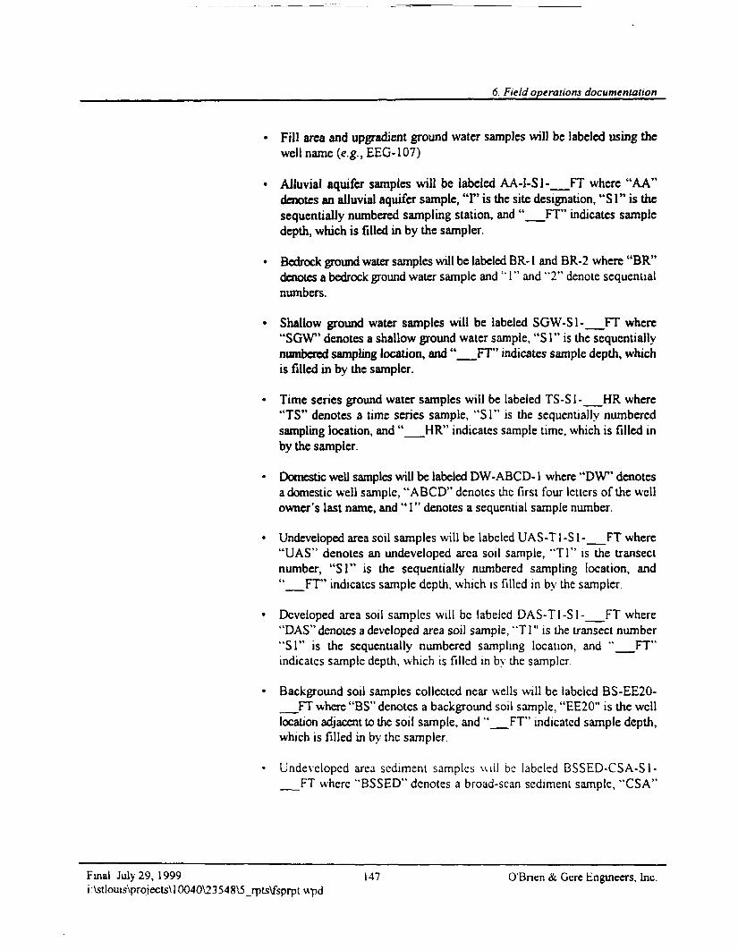
6. Field operations documentation
Fill area and upgradient ground water samples will be labeled using thewell name (e.g., EEC-107)
Alluvial aquifer samples will be labeled AA-I-S1-_FT where "AA"denotes an alluvial aquifer sample, T' is the site designation, "SI" is thesequentially numbered sampling station, and " FT' indicates sampledepth, which is filled in by the sampler.
Bedrock ground water samples will be labeled BR-1 and BR-2 where "BR"denotes a bedrock ground water sample and "1" and "2" denote sequentialnumbers.
Shallow ground water samples will be labeled SGW-S1- FT where"SOW" denotes a shallow ground water sample, "S1" is the sequentiallynumbered sampling location, and " FT' indicates sample depth, whichis filled in by the sampler.
Time series ground water samples will be labeled TS-S1-__HR where"TS" denotes a time series sample, "SI" is the sequentially numberedsampling location, and "__HR" indicates sample time, which is filled inby the sampler.
Domestic well samples will be labeled DW-ABCD-1 where "DW" denotesa domestic well sample, "ABCD" denotes the first four letters of the wellowner's last name, and "1" denotes a sequential sample number.
Undeveloped area soil samples will be labeled UAS-T1 -S 1 -__FT where"UAS" denotes an undeveloped area soil sample, "Tl" is the transectnumber, "SI" is the sequentially numbered sampling location, and"__FT' indicates sample depth, which is filled in by the sampler.
Developed area soil samples will be labeled DAS-T1-S1-__FT where"DAS" denotes a developed area soil sample, "Tl" is the transect number"SI" is the sequentially numbered sampling location, and "__FT"indicates sample depth, which is filled in by the sampler.
Background soil samples collected near wells will be labeled BS-EE20-__FT where "BS" denotes a background soil sample, "EE20" is the welllocation adjacent to the soil sample, and "__FT" indicated sample depth,which is filled in by the sampler
Undeveloped area sediment samples u i i l be labeled BSSED-CSA-S1-__FT where "BSSED" denotes a broad-scan sediment sample, "CSA"
Final July 29, 1999 147 O'Bnen & Gere Engineers, Inc.i : \stlouts\projects\ 10040\2 3 548\5_rpts\fspnpt wpd
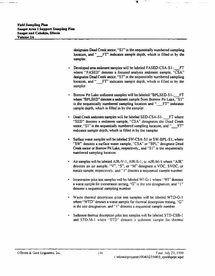
Field Sampling PlanSauget Area 1 Support Sampling PlanSauget and Cahokia, DlinouVolume 2A
designates Dead Creek sector, "SI" is the sequentially numbered samplinglocation, and "__FT" indicates sample depth, which is filled in by thesampler.
• Developed area sediment samples will be labeled FASED-CSA-S1 -__FTwhere "FASED" denotes a focused analysis sediment sample, "CSA"designates Dead Creek sector, "S1" is the sequentially numbered samplinglocation, and "__FT" indicates sample depth, which is filled in by thesampler.
• Borrow Pit Lake sediment samples will be labeled "BPLSED-S1 -__FTwhere "BPLSED" denotes a sediment sample from Borrow Pit Lake, "SI"is the sequentially numbered sampling location and "__FT" indicatessample depth, which is filled in by the sampler.
• Dead Creek sediment samples will be labeled SED-CSA-S1 -_FT where"SED" denotes a sediment sample, "CSA" designates the Dead Creeksector, "SI" is the sequentially numbered sampling location, and "__FT"indicates sample depth, which is filled in by the sampler.
• Surface water samples will be labeled SW-CSA-S1 or SW-BPL-S1, where"SW" denotes a surface water sample, "CSA" or "BPL" designate DeadCreek sector or Borrow Pit Lake, respectively,, and "S 1" is the sequentiallynumbered sampling location.
• Air samples will be labeled AIR-V-1, AIR-S-1, o; AlR-M-1 where "AIR"denotes an air sample, "V", "S", or "M" designate a VOC, SVOC, ormetals sample, respectively, and " 1" denotes a sequential sample number.
• Incineration pilot test samples will be labeled WI-G-1 where "WI" denotesa waste sample for incineration testing, "G" is the site designation, and "1"denotes a sequential sampling number
• Waste thermal desorption pilot test samples will be labeled WTD-G-1where "WTD" denotes a waste sample for thermal desorption testing, "G"is the site designation, and " 1" denotes a sequential sample number.
• Sediment thermal desorption pilot test samples will be labeled STD-CSB-1and STD-M-1 where "STD" denotes a sediment sample for thermal
OBnen &. Gere Engineers, Inc. 148 Final July 29, 1999i :\stlouis\projecls\ 10040V23 548\5_rp(s\fsprpt. wpd
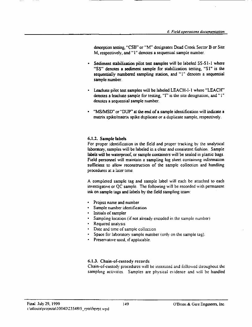
6. Field operations documentation
desorption testing, "CSB" or "M" designates Dead Creek Sector B or SiteM, respectively, and "1" denotes a sequential sample number.
Sediment stabilization pilot test samples will be labeled SS-S1-1 where"SS" denotes a sediment sample for stabilization testing, "SI" is thesequentially numbered sampling station, and "1" denotes a sequentialsample number.
Leachatc pilot test samples will be labeled LEACH-I-1 where "LEACH"denotes a leachate sample for testing, "I" is the site designation, and "1"denotes a sequential sample number.
"MS/MSD" or "DUP" at the end of a sample identification will indicate amatrix spike/matrix spike duplicate or a duplicate sample, respectively.
6.1.2. Sample labelsFor proper identification in the field and proper tracking by the analyticallaboratory, samples will be labeled in a clear and consistent fashion. Samplelabels will be waterproof, or sample containers will be sealed in plastic bags.Field personnel will maintain a sampling log sheet containing informationsufficient to allow reconstruction of the sample collection and handlingprocedures at a later time.
A completed sample tag and sample label will each be attached to eachinvestigative or QC sample. The following will be recorded with permanentink on sample tags and labels by the field sampling team:
• Project name and number• Sample number identification• Initials of sampler• Sampling location (if not already encoded in the sample number)• Required analysis• Date and time of sample collection• Space for laboratory sample number (only on the sample tag).• Preservative used, if applicable.
6.1.3. Chain-of-custody recordsChain-of-custody procedures will be instituted and followed throughout thesampling activities. Samples are physical evidence and will be handled
Final July 29, 1999 149 O'Bncn & Gere Engineers, Inc.i:\stlouis\projects\10040\23548\S_rpts\fsprpt.wpd
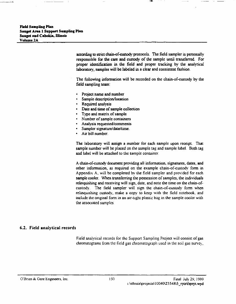
Field Sampling PlanSauget Area I Support Sampling PlanSauget and Cahokia, IllinoisVolume 2A
according to strict chain-of-custody protocols. The field sampler is personallyresponsible for the care and custody of the sample until transferred. Forproper identification in the field and proper tracking by the analyticallaboratory, samples will be labeled in a clear and consistent fashion.
The following information will be recorded on the chain-of-custody by thefield sampling team:
• Project name and number• Sample description/location• Required analysis• Date and time of sample collection• Type and matrix of sample• Number of sample containers• Analysis requested/comments• Sampler signature/date/time.• Air bill number.
The laboratory will assign a number for each sample upon receipt. Thatsample number will be placed on the sample tag and sample label. Both tagand label will be attached to the sample container.
A chain-of-custody document providing all information, signatures, dates, andother information, as required on the example chain-of-custody form inAppendix A, will be completed by the field sampler and provided for eachsample cooler. When transferring the possession of samples, the individualsrelinquishing and receiving will sign, date, and note the time on the chain-of-custody. The field sampler will sign the chain-of-custody form whenrelinquishing custody, make a copy to keep with the field notebook, andinclude the original form in an air-tight plastic bag in the sample cooler withthe associated samples
6.2. Field analytical records
Field analytical records for the Support Sampling Project will consist of gaschromatograms from the field gas chromatograph used in the soil gas survey,
O'Bnen & Gere Engineers, Inc. 150 Final July 29, 1999i :\stlouis\projects\ 10040V23 548\5_rpts\fsprpt.wpd
6. Field operations documentation
and field notebook entries for field instruments. Chromatograms will be tapedinto an analytical notebook. In addition to information printed on thechramatograms, field notes will be added as appropriate. Information detailedon each chromatogram will include:
• Sample number identification• Initials of sampler• Sampling location (if not already encoded in the sample number)
• Required analysis• Date and time of sample collection• Date and time of analysis• Instrument name• Column and detector type• Carrier gas and flowrate• Backflush time• Injection volume• Gain setting.
Only direct reading instrumentation will be employed in the field. The use ofpH, conductivity, and turbidity meters, a photoionization detector (PID), a realtime aerosol monitor (RAM), and thermometers will generate somemeasurements directly read from the meters following calibration by therespective manufacturer's recommendations. Such data will be written intofield notebooks immediately after measurements are taken. Calibrationrecords will also be recorded in the notebooks.
6.3. Data management and retention
The field data and documentation as descnbed in this section will become apart of the final evidence file. The final evidence file will be the centralrepository for all documents which constitute evidence relevant to samplingand analysis activities as described in this FSP and the QAPP. O'Brien &Gere is the custodian of the evidence file and maintains the contents ofevidence files for the site, including all relevant records, reported, logs, fieldnotebooks, pictures, subcontractor reports, data reviews, and the databasemanagement system.
Upon completion of the analyses, the project O'Bnen & Gere QAO will beginassimilating the field and laboratory notes In this way, the file for the samples
Final July 29, 1999 151 O'Bnen & Gere Engineers, Inc.i:\stlouis\projects\10040\23548\5_rpts\fsprpt\vpd
Field Sampling PlanSauget Area 1 Support Sampling PlanSauget and Caholda, DlinouVolume 2A
will be generated. The final file for the sample will be stored at O'Bnen &Gere and will consist of the following:
• Laboratory data packages, including summary and raw data from theanalysis of environmental and QC samples, chromatograms, mass spectra,calibration data, work sheets, and sample preparation notebooks
• Chain-of-custody records• Data validation reports.
The following documentation will supplement the cham-of-custody records:
• Field notebooks and data• Field collection report• Photographs and drawings• Progress and QA reports• Contractor and subcontractor reports• Correspondence.
The evidence file must be maintained in a secured, limited access area until allsubmittals for the project have been reviewed and approved, and for aminimum of six years past the submittal date of the final report
O'Bnen & Gere Engineers, Inc. 152 Final July 29, 1999i:\stlouis\projects\10040\23548\5_rpts\fsprpt.wpd
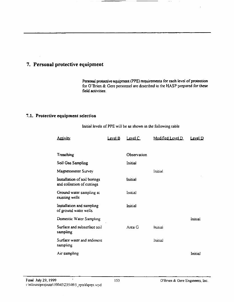
7. Personal protective equipment
Personal protective equipment (PPE) requirements for each level of protectionfor O'Brien & Gere personnel are described in the HASP prepared for thesefield activities.
7.1. Protective equipment selection
Initial levels of PPE will be as shown in the following table
Activity Level B Level C Modified Level D Level D
Trenching
Soil Gas Sampling
Magnetometer Survey
Installation of soil boringsand collection of cuttings
Ground water sampling atexisting wells
Installation and samplingof ground water wells
Domestic Water Sampling
Surface and subsurface soilsampling
Surface water and sedimentsampling
Air sampling
Observation
Initial
Initial
Initial
Initial
Area G
Initial
Initial
Initial
Initial
Initial
Final July 29, 1999i:\stlouis\projccts\10040\23548\5_rpts\fsprprupd
153 O'Bnen & Gere Engineers, Inc.

Field Sampling PlanSauget Area 1 Support Sampling PlanSaugct and Cahokia, DlinoisVolume 2A
O'Bnen & Gere Engineers, Inc. 154 Final July 29, 1999i:\stlouis\projecls\10040\23548\5_rpls\fsprpt.wpd
8. Sample packaging and shipping
A completed sample tag and sample label will each be attached to eachinvestigative or QC sample and the sample placed in a shipping container.Information to be recorded on sample tags and labels is described in section6.1.2. Information to be recorded on chain-of-custody forms is described insection 6.1.3. The sample identification system used in the field is describedin section 6.1.1.
Sampling containers will be packed in styrofoam sheets and put in plastic bagsto help prevent breakage and cross-contamination. Samples will be shippedin coolers, each containing a chain-of-custody form and ice and ice packs tomaintain inside temperature at approximately 4 °C. Sample coolers will thenbe sealed between the lid and sides of the cooler with a custody seal prior toshipment. The custody seal will be an adhesive-backed tape that easily rips ifit is disturbed. Samples will be shipped to the laboratory by commonovernight carrier or will delivered by O'Brien & Gere. The field samplingteam will send sample coolers to Savannah Labs. For samples collected fordioxm and dibenzofuran analysis, samples will be sent to Triangle Labs.Samples will not be sent to another laboratory without the permission ofUSEPA Region V. Sample transportation will comply with U.S. Departmentof Transportation and ICAO/1ATA (1999) regulations. Special samplingpacking provisions will be made for samples requiring additional protection.
Samples will remain in the custody of the sampler until transfer of custody iscompleted. Transfer consists of:
• Delivery of samples to the laboratory sample custodian• Signature of the laboratory sample custodian on the chain-of-custody
document as receiving the samples and signature of sampler asrelinquishing the samples
If a carrier is used to take samples between the sampler and the laboratory, acopy of the air bill must be attached to the chain-of-custody to maintain proofof custodv.
Final My 29, 1999 155 O'Bncn & Gere Engineers, Inc.i:\stlouis\projects\10040\23548\5_rpts\fsprpt.\vpd

Field Sampling PlanSauget Area 1 Support Sampling PlanSauget and Caholda, IllinoisVolume 2A
OBrien & Gere Engineers, Inc. 156 Final July 29, 1999i: Vstlouis\projects\ 10040\23 548\5_rpts\fsprpt.wpd
9. Investigation-derived wastes
Sampling activities will occur in widely-separated locations. Therefore,personnel and equipment decontamination will be accomplished at eachsampling area using temporary facilities. Chapter 8 of the HASP describespersonnel and monitoring equipment decontamination procedures andsupplies. PPE, disposable sampling equipment, cuttings, purge waters, andfield decontamination wastes will be collected at the point of generation andstored in temporary containers. PPE, solids, and liquids will be consolidatedin separate bulk containers at a central area. The sampling procedures havebeen developed to minimize the quantity of waste generated Additionalactivity-specific information on disposal of investigation-derived wastes iscontained in Chapter 5 of this FSP
Final July 29, 1999 157 O'Bnen & Gere Engineers, Inci:\stlouis\projects\10040\23548\5_rpts\fsprptvvpd

Field Sampling PlanSauget Area 1 Support Sampling PlanSauget and CahoUa, DlinouVolume 2A
O'Bnen &. Gere Engineers, inc. 158 Final July 29, 1999i \stlouis\projects\10040\23548\5_rpls\fsprpt.wpd
10. Field assessment/inspection
The performance audit is an independent check to evaluate the quality of databeing generated. The system audit is an on-site review and evaluation of thequality control practices, sampling procedures, and documentation procedures.
At the discretion of the O'Brien & Gerc PM, performance and system auditsof field activities will be conducted to verify that sampling and analyses areperformed in accordance with the procedures established in this FSP and theQAPP. The audits of field activities include two independent parts: internaland external audits.
The internal audits will be performed by the O'Bnen &. Gere QAO Theexternal audits will be performed by USEPA Region V
10.1. Field performance and system audits
10.1.1. Internal field auditsInfernal field audit responsibilities. Internal audits of field activitiesincluding sampling and field measurements will be conducted by the O'Brien& Gere QAO
Internal field audit frequency. These audits will verify that all establishedprocedures are being followed. Internal field audits will be conducted at leastonce at the beginning of the site sample collection activities and annuallythereafter.
Internal field audit procedures. The audits will include examination of fieldsampling records, field instrumentation operating records, sample collection,handling and packaging in compliance with the established procedures,maintenance of QA procedures, cham-of-custody. and other elements of thefield program. Follow up audits will be conducted to correct deficiencies andto verify that QA procedures are maintained throughout the project. The
Final July 29, 1999 159 O'Bnen & Gere Engineers, Inc.i:\stlouis\projects\lCXD40\23548\5_rpt5\fsprptwpd
Field Sampling PlanSauget Area 1 Support Sampling PlanSauget and Cahokia, DlinobVolume 2A
audits will involve review of field measurement records, instrumentationcalibration records, and sample documentadoa The areas of concern in a fieldaudit include:
• Sampling procedures• Decontamination of sampling equipment, if applicable• Chain-of-custody procedures• Standard operating procedures• Proper documentation in field notebooks.• Subcontractor procedures.
10.1.2. External field auditsExternal field audit responsibilities. External field audits may be conductedby USEPA Region V.
External field audit frequency. External field audits may be conducted at anytime during the field operations. These audits may or may not be announcedand are at the discretion of USEPA Region V
Overview of the external field audit process. External field audits will beconducted according to the field activity information presented in this FSP andthe QAPP.
OTBnen & Gere Engineers, Inc. 160 Final July 29, 1999i:\stlouis\projects\l0040\23548\5_rpts\fsprpt.wpd
11. Corrective action
Corrective action is the process of identifying, recommending, approving, andimplementing measures to counter unacceptable procedures or out-of-controlperformance which can affect data quality. Corrective action can occur duringfield activities, laboratory analyses, data validation, and data assessment.Corrective action proposed and implemented will be documented in the regularquality assurance reports to management. Corrective action should only beimplemented after approval by the O'Brien & Cere PM or the O'Brien & CereField Leader. If immediate corrective action is required, approvals secured bytelephone from the Project Manager should be documented in an additionalmemorandum.
For noncompliance problems, a formal corrective action program will bedeveloped and implemented at the time the problem is identified. The personwho identifies the problem will be responsible for notifying the O'Brien &Gere PM, who in turn will notify USEPA Region V Implementation ofcorrective action will be confirmed in writing through the same channels.Nonconformance with the established quality control procedures in the QAPPor FSP will be identified and corrected in accordance with the QAPP. USEPARegion V will issue a nonconformance report for each nonconformancecondition.
11.1. Field corrective action
Corrective action in the field can be needed when the sample network ischanged (i.e., more or less samples, sampling location changes, and relatedmodifications) or sampling procedures and/or field analytical proceduresrequire modification due to unexpected conditions. Technical staff and projectpersonnel will be responsible for reporting all suspected technical or QAnonconformances or suspected deficiencies of any activity or issued documentby reporting the situation to the O'Brien & Gere Field Leader The O'Brien& Gere Field Leader will be responsible for assessing the suspected problemsin consultation with the O'Brien & Gere PM on making a decision based onthe potential for the situation to impact the quality of the data. If it is decided
Final July 29. 1999 161 O'Brien & Gere Engineers, Inc.i:\stlouis\projects\10040\23548\5_rpts\fsprptwpd
Field Sampling PlanSauget Area 1 Support Sampling PlanSauget and Cahokia, DlinoiiVolume 2A
the situation requires a reportable nonconformance requiring corrective action,a nonconformance report will be initiated by the O'Brien & Gere PM.
The O'Brien & Gere PM will be responsible for verifying corrective actionsfor nonconformance are initiated by:
• Evaluating reported nonconformances• Controlling additional work on nonconforming items• Identifying disposition or action to be taken• Maintaining a log of nonconformances• Reviewing nonconformance reports and corrective actions taken• Verifying nonconformance reports are included in the final site
documentation in project files
If appropriate, the O'Brien & Gere Field Leader will verify no additional workdependent on the nonconforming activity is performed until the correctiveactions are completed. Corrective action for field measurements may include:
• Repeat the measurement to check the error• Check for proper adjustments for ambient conditions such as temperature• Check the batteries• Re-calibration• Check the calibration• Replace the instrument or measurement devices• Stop work (if necessary).
The O'Brien & Gere Field Leader is responsible for site activities. In this role,the O'Brien & Gere Field Leader at times is required to adjust the siteprograms to accommodate site-specific needs. When it becomes necessary tomodify a program, the responsible person notifies the O'Bnen & Gere FieldLeader of the anticipated change and implements the necessary changes afterobtaining the approval of the O'Brien & Gere Field Leader. The change in theprogram will be documented on the field change request (FCR) that will besigned by the initiators and the O'Brien & Gere Field Leader. The FCR foreach document will be numbered serially as required. The FCR will beattached to the file copy of the affected document. The O'Brien & Gere FieldLeader must approve the change in writing or verbally prior to fieldimplementation, if feasible If unacceptable, the action taken during the periodof deviation will be evaluated in order to evaluate the significance of anydeparture from established program practices and action taken.
O'Bnen & Gere Engineers, Inc. 162 Final July 29, 1999i \stlouis\projects\ 10040V23548\5_rpts\fsprpt.wpd
//. Corrective action
The O'Bnen & Gere Field Leader is responsible for controlling, tracking, andimplementing identified changes. Reports on changes will be distributed toafTected parties, which includes USEPA Region V.
Corrective action resulting from internal field audits will be implementedimmediately if data may be adversely affected due to unapproved or improperuse of approved methods. The O'Brien & Gere QAO will identify deficienciesand recommend corrective action to the O'Brien & Gere PM. Implementationof corrective actions will be performed by the O'Brien & Gere Field Leaderand the field team. Corrective action will be documented in the qualityassurance report to the project management.
Corrective actions will be implemented and documented in the field notebook.No staff member will initiate corrective action without prior communicationof findings through the proper channels. If corrective actions are insufficient,work may be stopped by USEPA Region V
The O'Brien & Gere QAO and Laboratory QAO may identify the need forcorrective action during either the data validation or data assessment.Potential types of corrective action may include resampling by the field teamor reinjection or reanalysis of samples by the laboratory.
These actions are dependent upon the ability to mobilize the field team orwhether the data to be collected is necessary to meet the required qualityassurance objectives. When the O'Brien & Gere QAO or Laboratory QAOidentifies a corrective action situation, it is the O'Bnen & Gere PM who willbe responsible for approving the implementation of corrective action,including resampling, during data assessment. Corrective actions of this typewill be documented by the O'Brien & Gere QAO and the Laboratory QAO.
Final July 29, 1999 163 O'Bnen & Gere Engineers, Inci:\stlouis\projects\10040\23548\5_rpts\fsprpt.wpd

Field Sampling PlanSauget Area 1 Support Sampling PlanSauget and Cahokia, DlinouVolume 2A
OBnen £. Gere Engineers, Inc. 164 Final July 29, 1999i:\stlouis\projects\10040\23548\5_rpts\fsprpt.wpd
References
Ecology and Environment, Inc. 1988. Expanded Site Investigation, DeadCreek Project Sites at Cahokia/Sauget, Illinois.
Ecology and Environment, Inc. 1997. Preliminary Ecological RiskAssessment for Sauget Area 1, Creek Segment F, Sauget, St. ClairCounty, Illinois.
Ecology and Environment, Inc. 1998. Sauget Area 1 Data Tables/Maps.USEPA Alternative Remedial Contracting Strategy (ARCS) Contract No.68-W8-0086. Work Assignment No. 47-5N60.
Geraghty and Miller. 1992. Site Investigation for Dead Creek Segment Band Sites L andM, Sauget-Cahokia, Illinois.
O'Brien & Gere Engineers, Inc. 1999. Health and Safety Plan, Sauget AreaI Support Sampling Project. Sauget and Cahokia. Illinois. Volume 2.
O'Brien & Gere Engineers, Inc. 1999. Quality Assurance Project Plan,Sauget Area 1 Support Sampling Project. Sauget and Cahokia. Illinois.Volume 2.
Solutia Inc. 1999. EE/CA and RI/FS Support Sampling Plan
U.S. Environmental Protection Agency (USEPA). 1988. Compendium ofMethods for the Determination of Toxic Organic Compounds in AmbientAir, EPAy600/4-89/017, June 1988, Research Triangle Park, NC
U.S. Environmental Protection Agency (USEPA) 1996 Method 1669:Sampling Ambient Water for Trace Metals at EPA Water QualityCriteria Levels. Draft EPA-821 -R-96-011
U.S. Environmental Protection Agency (USEPA) 1999 Final AdministrativeOrder by Consent. Sauget Area 1 Site. Sauget and Cahokia. Illinois.
Final July 29, 1999 165 O'Bnen & Gere Engineers, Inc.i:\stlouis\projects\10040\23548\5_rpts\fsprpt.wpd
Field Sampling PlanSauget Area 1 Support Sampling PlanSauget and Cabolda, DlinouVolume 2A ______
OBnen & Gere Engineers, Inc. 166 Final July 29, 1999i:\stlouis\projects\10040\23548V5_rpts\fsprpt.wpd

TABLES
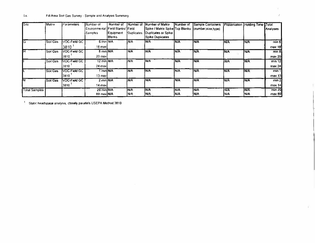
Ta Fill Area Soil Gas Survey - Sample and Analysis Summary
Site
G
H
1
L
N
Total Samples
Matrix
Soil Gas
Soil Gas
Soil Gas
Soil Gas
Soil Gas
Parameters
VOC-Field GC
3810 1
VOC-Field GC3810 1
VOC-Field GC3810 1
VOC-Field GC3810 1
VOC-Field GC3810 1
Number ofEnvironmentalSamples
6 min18 max
8 min20 max12 min
24 max1 min
13 max2 min
14 max29 min
89 max
Number ofField Blanks/EquipmentBlanksN/A
N/A
N/A
N/A
N/A
N/AN/A
Number ofFieldDuplicates
N/A
N/A
N/A
N/A
N/A
N/AN/A
Number of MatrixSpike / Matrix SpikeDuplicates or SpikeSpike DuplicatesN/A
N/A
N/A
N/A
N/A
N/AN/A
Number ofTrip Blanks
N/A
N/A
N/A
N/A
N/A
N/AN/A
Sample Containers(number, size. type)
N/A
N/A
N/A
N/A
N/A
N/AN/A
Preservation
N/A
N/A
N/A
N/A
N/A
N/AN/A
Holding Time
N/A
N/A
N/A
N/A
N/A
N/AN/A
TotalAnalyses
min 6max 18
min 8max 20min 12max 24
min 1max 13
min 2max 14min 29max 89
1 Static headspace analysis, closely parallels USEPA Method 3810
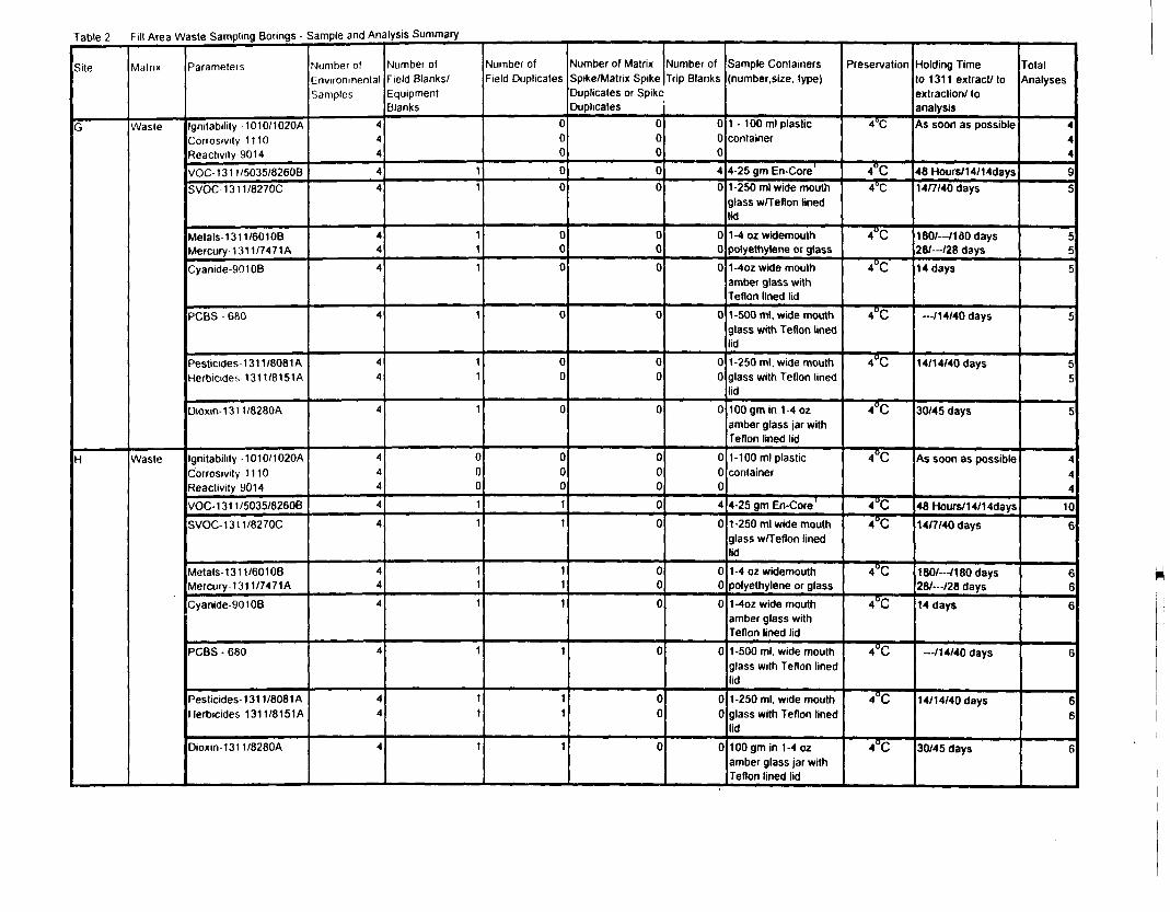
Table 2 Fill Area Waste Sampling Borings - Sample and Analysis Summary
Site
G
H
Matrix
Waste
Waste
Parameters
Ignitabilily 1010/1020ACorrosivity 1110Reactivity 9014VOC-1311/5035/8260BSVOC 1311/8270C
Metals- 1 3 11/601 OBMercury-1 31 1/7471ACyanide-90106
PCBS - 680
Pesticides 131 1/8081 AHerbicides 1311/8151A
Dioxin-1311/8280A
Ignitabilily 1010/1020ACorrosivity 1110Reactivity 9014VOC-1311/5035/8260B
SVOC-1311/8270C
Metals-1 3 11/601 OBMercury-131 1/7471A
Cyanide-90108
PCBS - 680
Pesticides 131 1/8081AHerbicides 131 1/81 51 A
Dioxin-1311/8280A
Number ofEnvironmentalSamples
444
44
44
4
4
44
4
444
4
4
44
4
4
44
4
Number ofField Blanks/EquipmentBlanks
11
111
1
11
1
000
11
111
1
11
1
Number ofField Duplicates
0000
000
0
00
0
00011
111
1
11
1
Mumber of MatrixSpike/Matrix SpikeDuplicates or SpikeDuplicates
0000
000
0
00
0
00000
000
0
00
0
Number ofTrip Blanks
0040
000
0
00
0
0004
0
000
0
00
0
Sample Containersnumber,size. type)
container
4-25 gm En-Core '1-250 ml wide mouthglass w/Teflon linedlid1 -4 oz widemouthpolyethylene or glass1 -4oz wide mouthamber glass withTeflon lined lid1-500 ml, widemouthglass with Teflon linedlid1-250 ml, wide mouthglass with Teflon linedlidtOOgmin 1-4 ozamber glass jar withTeflon lined lid1-1 00 ml plasticcontainer
4-25 gm En-Core'1-250 ml wide mouthglass w/Teflon linedlid1-4 oz widemouthpolyethylene or glass1 ~4oz wide mouthamber glass withTeflon lined lid1-500 ml, wide mouthglass with Teflon linedlid1-250 ml, widemouthglass with Teflon linedlid100gmin 1-4 ozamber glass jar withTeflon lined lid
Preservation
4°C
4°C4°C
4°C
4°C
4°C
4°C
4°C
4°C
4°C
4°C
4°C
4°C
4°C
4°C
4°C
Holding Timeto 1311 extract/ toextraction/ toanalysisAs soon as possible
48 Hours/14/14days14/7/40 days
180/— /1 30 days261— 128 days14 days
— /14/40 days
14/14/40 days
30/45 days
As soon as possible
48 Hours/14/14days14/7/40 days
180/--/180days287— /28 days14 days
—/1 4/40 days
14/14/40 days
30/45 days
TotalAnalyses
444
95
55
5
5
55
5
444
10
6
666
6
66
6
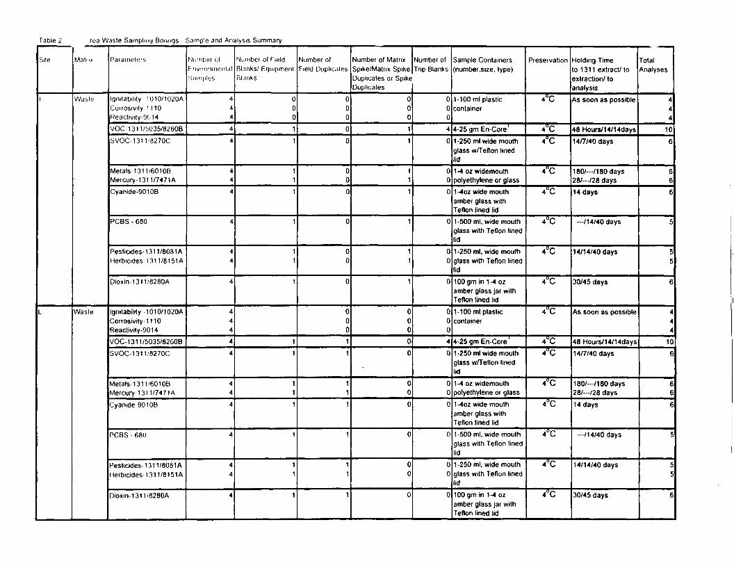
Table 2 rea Waste Sampling Borings - Sample and Analysis Summary
Site
1
L
Main*
Waste
Waste
Parameters
Igmtability 1010/1020ACorrosivity 1 1 10Reactivity-9014VOC-1311/^U35/8260B
SVOC-1311/8270C
Metals-131 1/6010BMercury-1311/7471ACyanide-90108
PCBS - 680
Pesticides-1 31 1/8081AHerbicides 131 1/81 51 A
Dioxin-1311/8280A
Igmtability 1010/1020ACorrosivity 1110Reactivity-9014VOC-1311/5035/82GOB
SVOC-1311/8270C
Metals-1 31 1/601 OBMercury-1 31 1/7471 ACyanide 901 OB
PCBS - 680
Pesticides- 131 1/8081 AHerbicides 131 1/81 51 A
Dioxin-1311/8280A
Number olhnvironmeiilalSamples
444
4
4
44
4
4
44
4
444
4
4
44
4
4
44
4
Number of fieldBlanks/ EquipmentRl.mks
000
11
111
1
11
1
11
111
1
11
1
Number ofField Duplicates
000
0
0
00
0
0
00
0
0001
1
11
1
1
11
1
Number of MatrixSpike/Matrix SpikeDuplicates or SpikeDuplicates
00011
111
1
11
1
00000
00
0
0
00
0
Number ofTrip Blanks
000
4
0
00
0
0
00
0
0004
0
000
0
00
0
Sample Containers(number.size, type)
1-100 ml plasticcontainer
4-25 gm En-Core'1-250 ml wide mouthglass w/Teflon linedlid1 -4 oz widemouthpolyethylene or glass1 -4oz wide mouthamber glass withTeflon lined lid1 -500 ml, wide mouthglass with Teflon linedlid1-250 ml. widemouthglass with Teflon linedlid100gm in 1-4 ozamber glass jar withTeflon lined lid1-100 ml plasticcontainer
4-25 gm En-Core '1-250 ml wide mouthglass w/Teflon linedlid1-4 oz widemouthpolyethylene or glass1 -4oz wide mouthamber glass withTeflon lined lid1-500 ml, wide mouthglass with Teflon linedlid1-250 ml, wide mouthglass with Teflon linedlid100 gm in 1-4 ozamber glass jar withTeflon lined lid
Preservation
4°C
4"C
4°C
4°C
4°C
4°C
4°C
4°C
4°C
4"C
4"C
4°C
4°C
4°C
4°C
4°C
Holding Timeto 1311 extract/ toextraction/ toanalysisAs soon as possible
48 Hours/14/14days14/7/40 days
180/-/180days261— 126 days14 days
— /14/40 days
14/1 4/40 days
30/45 days
As soon as possible
48 Hours/1 4/1 4days14/7/40 days
180/— /1 80 days28/— /28 days14 days
— /1 4/40 days
14/1 4/40 days
30/45 days
TotalAnalyses
444
106
666
5
t.c
6
444
10
6
66
6
i
ii
6
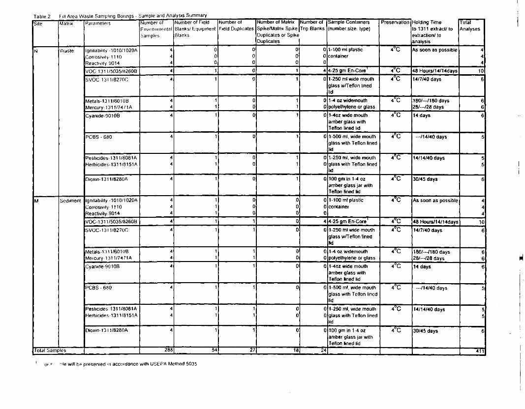
Table 2 Fill Area Waste Sampling Borings - Sample and Analysis SummarySite
N
M
Matrix
Waste
Sediment
Total Samples
Parameters
Ignitability 1010/1020AConosivity 11 10Reactivity 9014
VOC 131 I/5035/8260B
SVOC 1311/8270C
Metals- 1 3 11/601 OBMercury- 1311/7471 A
Cyamde-90tOB
RGBS - 680
Pesticides 131 1/8081 AHerbicides 131 1/8151A
Dioxm-1311/8280A
Ignitability -1010/1020ACorrosivily-1110Reactivity 9014VOC-1311/5035/8260BSVOC-1311/8270C
Metais-i:ni/60iuBMercury 131 1/74 71 A
Cyanide-9010B
PCBS - 680
Pesticides 131 1/8081AHerbicides 131 1/8151A
Dioxin-13l1/8280A
Number ofFnvironmentalSamples
444
4
4
44
4
4
44
4
444
4
4
44
4
4
44
4
288
Number of FieldBlanks/ EquipmentBlanks
0001
1
11
1
1
11
1
111
1
1
11
1
1
11
1
54
Number ofField Duplicates
000
00
000
0
00
0
00011
111
1
11
1
27
Spike/Matrix SpikeDuplicates or SpikeDuplicates
00011
111
1
11
1
00000
00
0
0
00
0
18
Trip Blanks
000
4
0
00
0
0
00
0
000
4
0
000
0
00
0
24
number.size type)
1-1 00 ml plasticcontainer
4-25 gm En-Core '1-250 ml wide mouthglass w/Teflon linedlid1-4 oz wktemouthpolyethylene or glass1-4oz wide mouthamber glass withTeflon lined lid1-500 ml, wide mouthglass with Teflon linedlid1 -250 ml, wide mouthglass with Teflon linedlid100gmin 1-4 ozamber glass jar withTeflon lined lid1-1 00 ml plasticcontainer
4-25 gm En-Core '1-250 ml wide mouthglass w/Teflon linedlid1-4 oz widemouthpolyethylene or glass1-4oz wide mouthamber glass withTeflon lined lid1-500 ml, wide mouthglass with Teflon linedlid1-250 ml, wide mouthglass with Teflon linedlidlOOgmin 1-4 ozamber glass jar withTeflon lined lid
Preservation
4UC
4°C
4°C
4°C
4°C
4°C
4°C
4°C
4°C
4"C
4°C
4°C
4°C
4°C
4°C
4°C
Holding Timeo 1311 extract/ toextraction/ toanalysisAs soon as possible
48 Hours/1 4/1 4days14/7/40 days
180/— /1 80 days261—128 days14 days
~/1 4/40 days
14/14/40 days
30/45 days
As soon as possible
48 Hours/1 4/1 4days14/7/40 days
180/— /180 days28A--/28 days14 days
— /14/40 days
14/1 4/40 days
30/45 days
TotalAnalyses
444
10
6
66
6
c
c
c
6
444
10
6
666
t
t
t
6
411
-IB will be preserved in accoidance with USEPA Method 5035
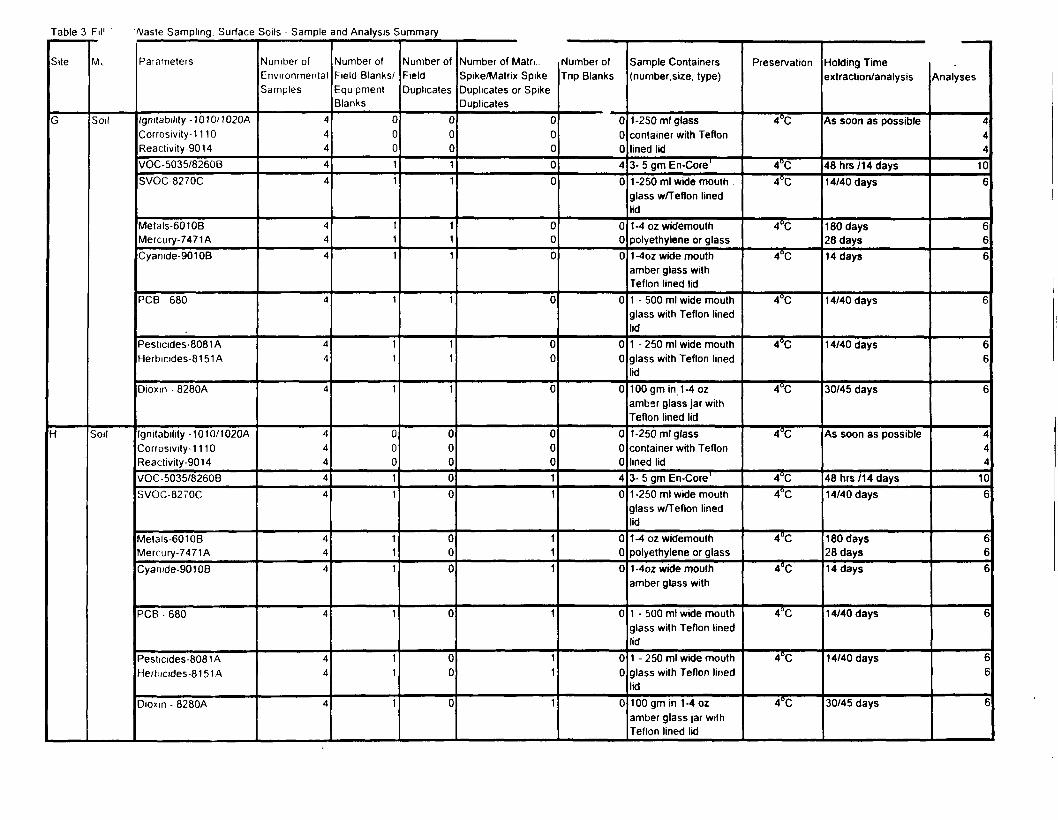
Table 3 Fil1 " /Vaste Sampling. Surface Soils - Sample and Analysis Summary
Site
G
H
M.
Soil
Soil
Parameters
lgmtability-1010/1020ACorrosivity-1 1 10Reactivity-9014VOC-5035/8260BSVOC-8270C
Metals-60106Mercury-7471ACyanide-90108
PCB - 680
Pesticides-8081 AHerbicides-8151 A
Dioxin - 8280A
lgnilability-1010/1020ACorrosivity-1110Reactivity-9014VOC -5035/82608SVOC-8270C
Metals-6010BMercury-7471ACyanide-90108
PCB - 680
Pesticides-8081AHertiicides-8151A
Dioxm - 8280A
Number ofEnvironmentalSamples
44444
44
4
4
44
4
444
4
4
44
4
4
44
4
Number ofField Blanks/EquipmentBlanks
00011
111
1
11
1
00011
111
1
11
1
Number ofFieldDuplicates
00011
111
1
11
1
00000
000
0
00
0
Number of Matn..Spike/Matrix SpikeDuplicates or SpikeDuplicates
00000
000
0
00
0
00011
111
1
11
1
Number ofTrip Blanks
00040
000
0
00
0
00040
000
0
00
0
Sample Containers(number.size, type)
1-250 ml glasscontainer with Teflonlined lid3- 5 gm En-Core'1-250 ml wide mouth .glass w/Teflon linedlid1-4 oz widemouthpolyethylene or glass1 -4oz wide mouthamber glass withTeflon lined lid1 - 500 ml wide mouthglass with Teflon linedlid1 - 250 ml wide mouthglass with Teflon linedlid100 gm in 1-4 ozamber glass jar withTeflon lined lid1-250 ml glasscontainer with Teflonlined lid3- 5 gm En-Core1
1-250 ml wide mouthglass w/Teflon linedlid1-4 oz widemouthpolyethylene or glass1-4oz wide mouthamber glass with
1 - 500 ml wide mouthglass with Teflon linedlid1 - 250 ml wide mouthglass with Teflon linedlid100 gm in 1-4 ozamber glass jar withTeflon lined lid
Preservation
4°C
4°C4°C
4°C
4°C
4°C
4°C
4°C
4°C
4°C4°C
4°C
4°C
4°C
4°C
4°C
Holding Timeextraction/analysis
As soon as possible
48hrs/14days14/40 days
180 days28 days14 days
14/40 days
14/40 days
30/45 days
As soon as possible
48hrs/14days14/40 days
180 days28 days14 days
14/40 days
14/40 days
30/45 days
Analyses
444
106
666
6
66
6
444
106
666
6
66
6
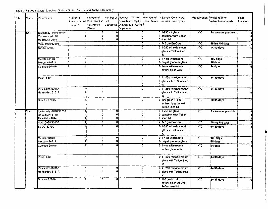
Table 3 Fill Aiea Waste Sampling, Surface Soils - Sample and Analysis Summary
Site
1
L
Matrix
Soil
Soil
Parameters
Ignitability -1010/1020ACorrosivity-1 1 10Reactivity-9014VOC-5035/8260BSVOC-8270C
Metals-601 OBMercury-7471ACyanide-90108
PCB - 680
Pesticides-8081 AHerbicides-81 51A
Dioxin - 8280A
lgrutability-1010/1020ACorrosivity-1 1 10Reactivity-9014VOC-5035/8260BSVOC-8270C
Metals-601 OBMercury-7471ACyanide-90108
PCB -680
Pesticides-8081 AHerbicides-8151A
Dioxin - 8280A
Number ofEnvironmentalSttrnples
44444
444
4
44
4
444
4
4
444
4
44
4
Number ofField Blanks/EquipmentBlanks
00011
111
1
11
1
00011
111
1
11
1
Number ofFieldDuplicates
00011
111
1111
1
00000
000
0
00
0
Number of MatrixSpike/Matrix SpikeDuplicates or SpikeDuplicates
00000
000
0000
0
00000
000
0
00
0
Number ofTrip Blanks
00040
000
0000
0
00040
000
0
00
0
Sample Containers(number.size, type)
1-250 ml glasscontainer with Teflonlined lid3- 5 gm En-Core1
1-250 ml wide mouthglass w/Teflon linedlid1 -4 oz widemouthpolyethylene or glass1 -4oz wide mouthamber glass with
1 - 500 ml wide mouthglass with Teflon linedlid1 - 250 ml wide mouthglass with Teflon linedlid100 gm in 1-4 ozamber glass jar withTeflon lined lid1-250 ml glasscontainer with Teflonlined lid3- 5 gm En-Core1
1-250 ml wide mouthglass w/Teflon linedlid1 -4 oz widemouthpolyethylene or glass1-4oz wide mouthamber glass with
1 - 500 ml wide mouthglass with Teflon linedlid1 - 250 ml wide mouthglass with Teflon linedlid100 gm in 1-4 ozamber glass jar withTeflon lined lid
Preservation
4°C
4°C4°C
4°C
4°C
4°C
4°C
4°C
4°C
4°C4°C
4°C
4°C
4°C
4°C
4°C
Holding Timeextraction/analysis
As soon as possible
48 hrs /14 days14/40 days
180 days28 days14 days
14/40 days
14/40 days
30/45 days
As soon as possible
48 hrs /14 days14/40 days
180 days28 days14 days
14/40 days
14/40 days
30/45 days
TotalAnalyses
444
106
666
6
66
6
44495
555
5
55
5
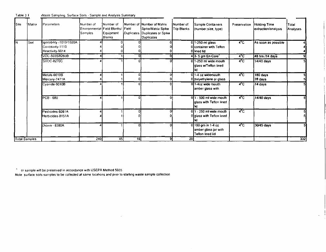
Table 3 F \A/aste Sampling. Surface Soils - Sample and Analysis Summary
Site
N
Matrix
Soil
Total Samples
Parameters
Ignitabihty -1010/1020ACorrosivity-11 10Reactivity-9014VOC-5035/8260BSVOC-8270C
Metals-60108Mercury-7471 ACyamde-9010B
PCB-680
Pesticides-8081 AHerbicides-8151A
Dioxm - 8280A
Number ofEnvironmentalSamples
44444
444
4
44
4
240
Number ofField Blanks/EquipmentBlanks
00011
111
1
11
1
45
Number ofFieldDuplicates
00000
000
0
00
0
18
Number of MatrixSpike/Matrix SpikeDuplicates or SpikeDuplicates
00000
000
0
00
0
9
Number ofTrip Blanks
00040
000
0
00
0
20
Sample Containers(number, size, type)
1-250 ml glasscontainer with Teflonlined lid3- 5 gm En-Core'1 -250 ml wide mouthglass w/Teflon linedlid1 -4 oz wklemouthpolyethylene or glass1 -4oz wide mouthamber glass with
1 - 500 ml wide mouthglass with Teflon linedlid1 - 250 ml wide mouthglass with Teflon linedlid100 gm in 1-4 ozamber glass jar withTeflon lined lid
Preservation
4°C
4°C4°C
4°C
4°C
4°C
4°C
4°C
Holding Timeextraction/analysis
As soon as possible
48hrs/14days14/40 days
180 days28 days14 days
14/40 days
30/45 days
TotalAnalyses
44495
555
5
55
C
332
1 or sample will be preserved in accordance with USEPA Method 5035Note surface soils samples to be collected at same locations and prior to starting waste sample collection
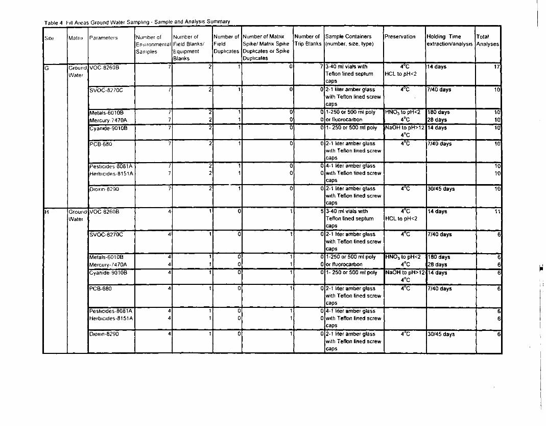
Table 4 Fill Areas Ground Water Sampling - Sample and Analysis Summary
Site
G
H
Matrix
GroundWater
GroundWater
Parameters
VOC-8260B
SVOC-8270C
Metals-60108Mercury-7470ACyanide 901 OB
PCB-680
Pesticides-8081AHerbicides-8151A
Dioxm-8290
VOC8260B
SVOC-8270C
Metals-601 OBMercury-7470ACyanide-90108
PCB-680
Pesticides-8081AHerbicides-8151A
Dioxm-8290
Number ofEnvironmentalSamples
7
7
777
7
77
7
4
4
444
4
44
4
Number ofField Blanks/EquipmentBlanks
2
2
222
2
22
2
1
1
111
1
11
1
Number ofFieldDuplicates
1
1
111
1
11
1
0
0
000
0
00
0
Number of MatrixSpike/ Matrix SpikeDuplicates or SpikeDuplicates
0
0
000
0
00
0
1
1
111
1
11
1
Number ofTrip Blanks
7
0
000
0
00
0
5
0
000
0
00
0
Sample Containersinumber, size, type)
3-40 ml vials withTeflon lined septumcaps2-1 liter amber glasswith Teflon lined screwcaps1-250 or 500 ml polyor fluorocarbon1-250 or 500 ml poly
2-1 liter amber glasswith Teflon lined screwcaps4-1 liter amber glasswith Teflon lined screwcaps2-1 liter amber glasswith Teflon lined screwcaps3-40 ml vials withTeflon lined septumcaps2-1 liter amber glasswith Teflon lined screwcaps1-250 or 500 ml polyor fluorocarbon1- 250 or 500 ml poly
2-1 liter amber glasswith Teflon lined screwcaps4-1 liter amber glasswith Teflon lined screwcaps2-1 liter amber glasswith Teflon lined screwcaps
Reservation
4°CHCL to pH<2
4°C
HNO3 to pH<24°C
NaOHtopH>124°C4°C
4°C
4°CHCL to pH<2
4°C
HNC-3 to pH<24°C
NaOH to pH>124°C4°C
4°C
Holding Timeextraction/analysis
14 days
7/40 days
180 days28 days14 days
7/40 days
30/45 days
14 days
7/40 days
180 days28 days14 days
7/40 days
30/45 days
TotalAnalyses
17
10
101010
10
1010
10
11
6
666
6
66
6
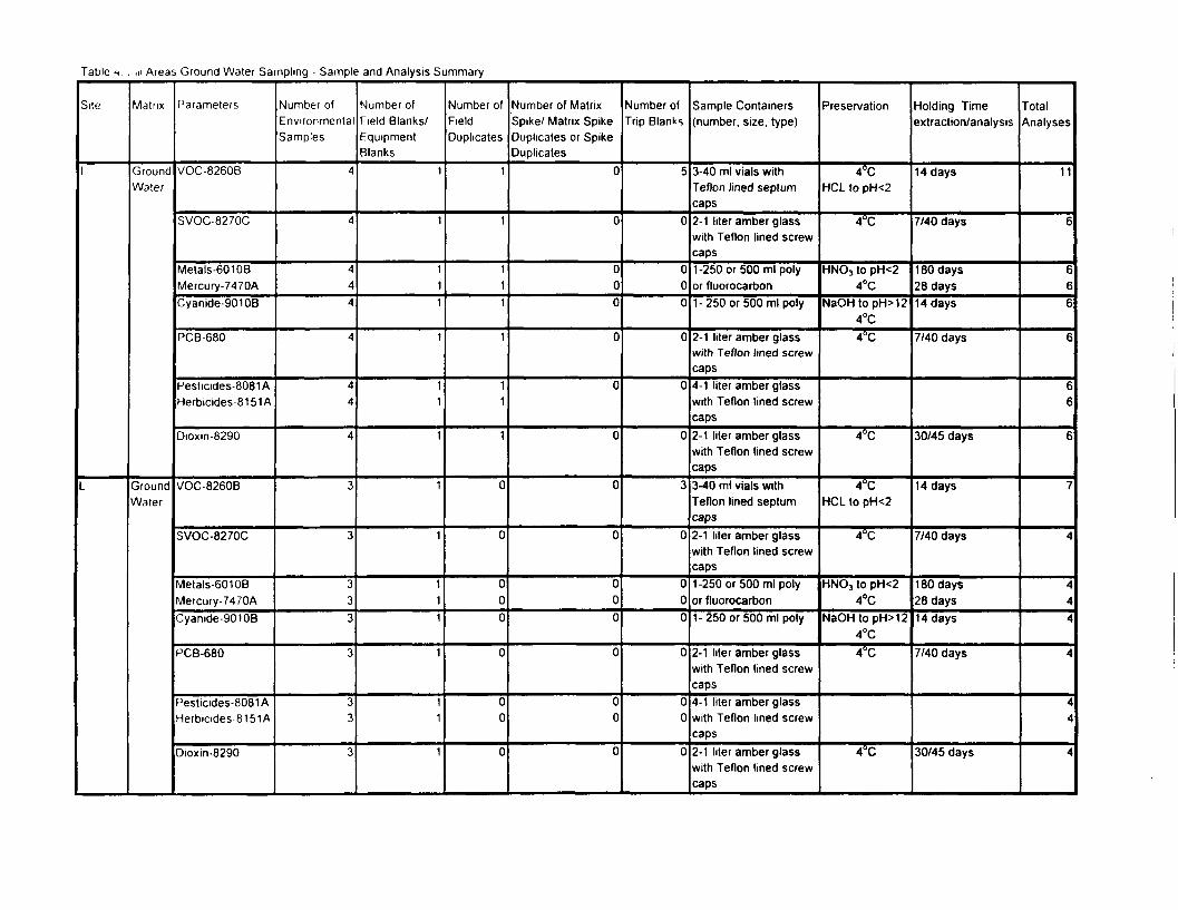
Table t . HI Areas Ground Water Sampling - Sample and Analysis Summary
Site
1
Matrix
GroundWater
GroundWater
Parameters
VOC-8260B
SVOC-8270C
Metals-60108Mercury-7470ACyanide-90108
PCB-680
Pesticides-8081 AHerbicides-8151A
Dioxin-8290
VOC-8260B
SVOC-8270C
Metals-60108Mercury-74 70ACyanide-90108
PCB-680
Pesticides-8081AHerbicides-8151A
Dioxin-8290
Number ofEnvironmentalSamples
4
4
444
4
44
4
3
3
333
3
33
3
Number ofField Blanks/EquipmentBlanks
1
1
111
1
11
1
1
1
111
1
11
1
Number ofFieldDuplicates
1
1
111
1
11
1
0
0
000
0
00
0
Number of MatrixSpike/ Matrix SpikeDuplicates or SpikeDuplicates
0
0
000
0
0
0
0
0
000
0
00
0
Number ofTrip Blanks
5
0
000
0
0
0
3
0
000
0
00
0
Sample Containers(number, size, type)
3-40 ml vials withTeflon lined septumcaps2-1 liter amber glasswith Teflon lined screwcaps1-250 or 500 ml polyor fluorocarbon1-250 or 500 ml poly
2-1 liter amber glasswith Teflon lined screwcaps4-1 liter amber glasswith Teflon lined screwcaps2-1 liter amber glasswith Teflon lined screwcaps3-40 ml vials withTeflon lined septumcaps2-1 liter amber glasswith Teflon lined screwcaps1-250 or 500 ml polyor fluorocarbon1-250 or 500 ml poly
2-1 liter amber glasswith Teflon lined screwcaps4-1 liter amber glasswith Teflon lined screwcaps2-1 liter amber glasswith Teflon lined screwcaps
Preservation
4°CHCL to pH<2
4°C
HNOj to pH<24°C
NaOHtopH>124°C4°C
4°C
4°CHCL to pH<2
4°C
HNO3 to pH<24°C
NaOHtopH>124°C4°C
4°C
Holding Timeextraction/analysis
14 days
7/40 days
1 80 days28 days14 days
7/40 days
30/45 days
14 days
7/40 days
180 days28 days14 days
7/40 days
30/45 days
TotalAnalyses
11
6
666
6
66
6
7
4
444
4
44
4
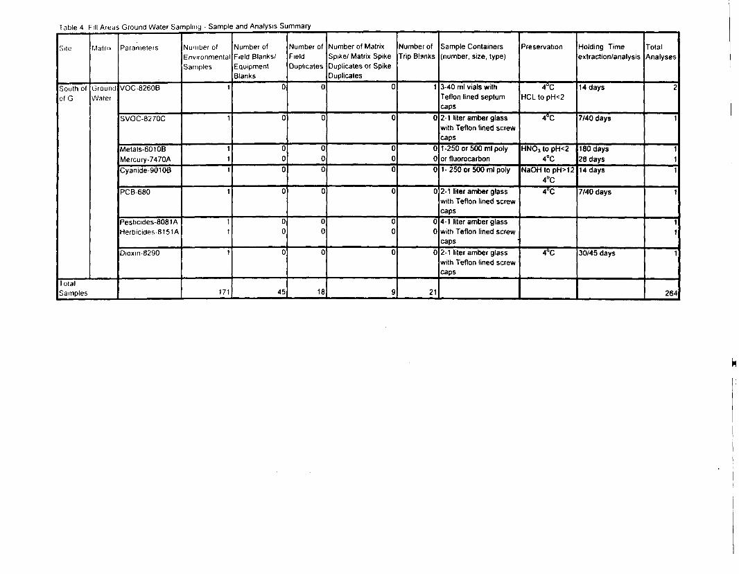
Table 4 Fill Areas Ground Water Sampling - Sample and Analysis Summary
Site
South ofof G
Matrix
GroundWater
TotalSamples
Parameters
VOC-8260B
SVOC-8270C
Metals-601 OBMercury-7470ACyanide-90108
PCB-680
Pesticides-8081 AHerbicides-8151A
Dioxm-8290
Number ofEnvironmentalSamples
1
1
111
1
11
1
171
Number ofField Blanks/EquipmentBlanks
0
0
000
0
00
0
45
Number ofFieldDuplicates
0
0
000
0
00
0
18
Number of MatrixSpike/ Matrix SpikeDuplicates or SpikeDuplicates
0
0
000
0
00
0
9
Number ofTrip Blanks
1
0
000
0
00
0
21
Sample Containers(number, size, type)
3-40 ml vials withTeflon lined septumcaps2-1 liter amber glasswith Teflon lined screwcaps1-250 or 500 ml polyor fluorocarbon1-250 or 500 ml poly
2-1 liter amber glasswith Teflon lined screwcaps4-1 liter amber glasswith Teflon lined screwcaps2-1 liter amber glasswith Teflon lined screwcaps
Preservation
4°CHCL to pH<2
4°C
HNO3 to pH<24°C
NaOHtopH>124°C4°C
4°C
Holding Timeextraction/analysis
14 days
7/40 days
180 days28 days14 days
7/40 days
30/45 days
TotalAnalyses
2
1
111
1
11
1
264
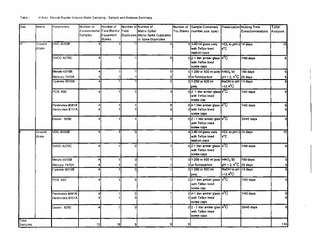
Table . ill Area Alluvial Aquifer Ground Water Sampling - Sample and Analysis Summary
Site
H
Matrix
GroundWater
GroundWater
TotalSamples
Parameters
VOC-8260B
SVOC-8270C
Metals-601 OBMercury-7470ACyanide-90108
PCB- 680
Pesticides-8081AHerbicides-8151 A
Dioxin - 8290
VOC-8260B
SVOC-8270C
Metals-601 OBMercury 7470ACyanide-90106
PCB- 680
Pesticides-8081AHerbicides-81 51 A
Dioxin - 8290
Number ofEnvironmentalSamples
4
4
4
44
4
44
4
4
4
4
44
4
44
4
72
Number ofField Blanks/EquipmentBlanks
1
1
111
1
11
1
1
1
111
1
11
1
18
Number ofFieldDuplicates
1
1
111
1
11
1
0
0
0
00
0
00
0
9
Number ofMatrix Spike/Matrix Spike Duplicatesor Spike Duplicates
0
0
000
0
00
0
1
1
1
11
1
11
1
9
Number ofTrip Blanks
4
0
000
0
00
0
4
0
000
0
00
0
8
Sample Containers(number.size, type)
3-40 ml glass vialswith Teflon linedseptum caps2-1 liter amber glasswith Teflon linedscrew caps1-250 or 500 ml polyor fluorocarbon1-250 or 500 mlpoly2 -1 liter amber glasswith Teflon linedscrew cap4-1 liter amber glasswith Teflon linedscrew caps2 - 1 liter amber glaswith Teflon linedscrew caps3-40 ml glass vialswith Teflon linedseptum caps2-1 liter amber glasswith Teflon linedscrew caps1-250 or 500 ml polyor fluorocarbon1-250 or 500 mlpoly2-1 liter amber glasswith Teflon linedscrew cap4-1 liter amber glasswith Teflon linedscrew caps2 - 1 liter amber glaswith Teflon linedscrew caps
Preservation
HCL to pH<24°C
4°C
HNO3 tO
pH < 2, 4°CNaOH to pH>12,4°C
4°C
4°C
4°C
HCL to pH<24°C
4°C
HNO3 tO
pH < 2, 4°CNaOH to pH>12,4°C
4°C
4°C
4°C
Holding TimeExtraction/analysis
14 days
7/40 days
180 days28 days14 days
7/40 days
7/40 days
30/45 days
14 days
7/40 days
180 days28 days14 days
7/40 days
7/40 days
30/45 days
TotalAnalyses
10
6
666
6
66
6
10
6
666
6
66
6
116
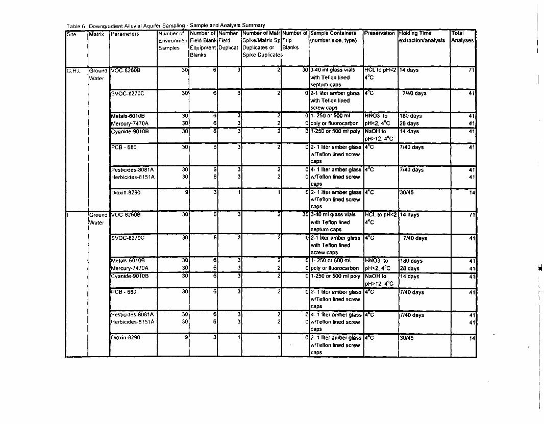
Table 6 Downgradient Alluvial Aquifer Sampling - Sample and Analysis SummarySite
G.H.L
1
Matrix
GroundWater
GroundWater
Parameters
VOC-8260B
SVOC-8270C
Metals-6010BMercury-7470ACyanide-90108
PCB - 680
Pesticides-8081 AHerbicides-81 51 A
Dioxin-8290
VOC-8260B
SVOC-8270C
Metals-601 OBMercury-7470ACyanide-9010B
PCB - 680
Pesticides-8081AHerbicides-81 51 A
Dioxin-8290
Number ofEnvironmenSamples
30
30
303030
30
3030
9
30
30
303030
30
3030
9
Number ofField BlankEquipmentBlanks
6
6
666
6
66
3
6
6
666
6
66
3
NumberFieldDuplicat
3
3
333
3
33
1
3
3
333
3
33
1
Number of MatrSpike/Matrix SpDuplicates orSpike Duplicate!
2
2
222
2
22
1
2
2
222
2
22
1
Number ofTripBlanks
>
30
0
000
0
00
0
30
0
000
0
00
0
Sample Containers(number, size, type)
3-40 ml glass vialswith Teflon linedseptum caps2-1 liter amber glasswith Teflon linedscrew caps1-250 or 500 mlpoly or fluorocarbon1-250 or 500 ml poly
2- 1 liter amber glassw/Teflon lined screwcaps4- 1 liter amber glassw/Teflon lined screwcaps2- 1 liter amber glassw/Teflon lined screwcaps3-40 ml glass vialswith Teflon linedseptum caps2-1 liter amber glasswith Teflon linedscrew caps1-250 or 500 mlpoly or fluorocarbon1-250 or 500 ml poly
2- 1 liter amber glassw/Teflon lined screwcaps4- 1 liter amber glassw/Teflon lined screwcaps2- 1 liter amber glassw/Teflon lined screwcaps
Preservation
HCL to pH<24°C
4°C
HNO3 topH<2, 4°CNaOH topH>12. 4°C4°C
4°C
4°C
HCL to pH<24°C
4°C
HNO3 topH<2, 4°CNaOH topH>12, 4°C4°C
4°C
4°C
Holding Timeextraction/analysis
14 days
7/40 days
180 days28 days14 days
7/40 days
7/40 days
30/45
14 days
7/40 days
180 days28 days14 days
7/40 days
7/40 days
30/45
TotalAnalyses
71
41
414141
41
4141
14
71
41
414141
41
4141
14
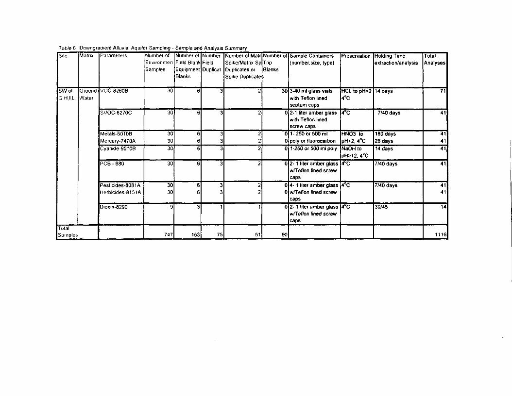
Table 6 Downgradient Alluvial Aquifer Sampling - Sample and Analysis SummarySite
SWofG H,I,L
Matrix
GroundWater
TotalSamples
Parameters
VOC-8260B
SVOC-8270C
Metals-601 OBMercury-7470ACyanide-90106
PCB - 680
Pesticides-8081 AHerbicides-81 51 A
Dioxm-8290
Number ofEnvironmenSamples
30
30
303030
30
3030
9
747
Number ofField BlankEquipmentBlanks
6
6
666
6
66
3
153
NumberFieldDuplicat
3
3
333
3
33
1
75
Number of MatrSpike/Matrix SpDuplicates orSpike Duplicate
2
2
222
2
22
1
51
Number ofTripBlanksi
30
0
000
0
00
0
90
Sample Containers(number, size, type)
3-40 ml glass vialswith Teflon linedseptum caps2-1 liter amber glasswith Teflon linedscrew caps1-250 or 500 mlpoly or fluorocarbon1-250 or 500 ml poly
2- 1 liter amber glassw/Teflon lined screwcaps4- 1 liter amber glassw/Teflon lined screwcaps2- 1 liter amber glassw/Teflon lined screwcaps
Preservation
HCL to pH<24°C
4°C
HNO3 topH<2, 4°CNaOH topH>12. 4°C4°C
4°C
4*C
Holding Timeextraction/analysis
14 days
7/40 days
180 days28 days14 days
7/40 days
7/40 days
30/45
TotalAnalyses
71
41
414141
41
4141
14
1116
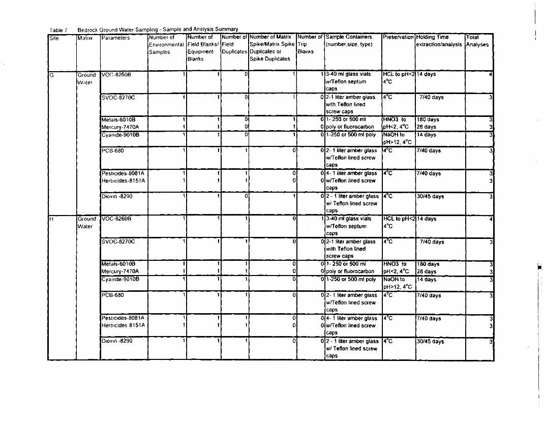
Table 7 Bedrock Ground Water Sampling - Sample and Analysis SummarySite
G
H
Matrix
GroundWater
GroundWater
Parameters
VOC-8260B
SVOC-8270C
Metals-60108Mercury-7470ACyanide-9010B
PCB-680
Pesticides-8081AHerbicides-8151A
Dioxm -8290
VOC-8260B
SVOC-8270C
Metals-60106Mercury-7470ACyanide-90108
PCB-680
Pesticides-8081AHerbicides-8151A
Dioxm -8290
Number ofEnvironmentalSamples
1
1
111
1
11
1
1
1
111
1
11
1
Number ofField Blanks/EquipmentBlanks
1
1
111
1
11
1
1
1
111
1
11
1
Number ofFieldDuplicates
0
0
000
1
11
0
1
1
111
1
11
1
Number of MatrixSpike/Matrix SpikeDuplicates orSpike Duplicates
1
1
111
0
00
1
0
0
000
0
00
0
Number ofTripBlaims
1
0
000
0
00
0
1
0
000
0
00
0
Sample Containers(number.size, type)
3-40 ml glass vialsw/Teflon septumcaps2-1 liter amber glasswith Teflon linedscrew caps1-250 or 500 mlpoly or fluorocarfaon1-250 or 500 ml poly
2- 1 liter amber glassw/Teflon lined screwcaps4- 1 liter amber glassw/Teflon lined screwcaps2 - 1 liter amber glassw/ Teflon lined screwcaps3-40 ml glass vialsw/Teflon septumcaps2-1 liter amber glasswith Teflon linedscrew caps1-250 or 500 mlpoly or fluorocarbon1 -250 or 500 ml poly
2- 1 liter amber glassw/Teflon lined screwcaps4- 1 liter amber glassw/Teflon lined screwcaps2 - 1 liter amber glassw/ Teflon lined screwcaps
Preservation
HCL to pH<24°C
4°C
HNO3 topH<2, 4°CNaOH topH>12, 4°C4^
4°C
4°C
HCL to pH<24°C
4°C
HNO3 topH<2, 4°CNaOH topH>12, 4°C4°C
4°C
4°C
Holding Timeextraction/analysis
14 days
7/40 days
180 days28 days14 days
7/40 days
7/40 days
30/45 days
14 days
7/40 days
180 days28 days14 days
7/40 days
7/40 days
30/45 days
TotalAnalyses
4
3
333
3
33
3
4
3
33
3
3
33
3
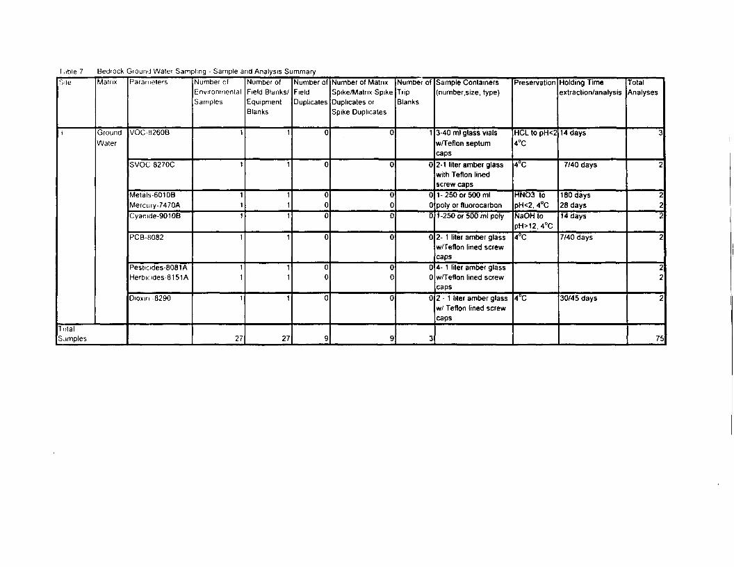
I ,ible 7 Bedrock Ground Water Sampling - Sample and Analysis SummarySite
1
Matrix
GroundWater
TotalSamples
Parameters
VOC-8260B
SVOC 8270C
Metals 601 OBMercury-7470ACyanide-90106
PCB8082
Pestiades-8081AHerbicides-8151A
DIOXIII -8290
Number ofEnvironmentalSamples
1
1
111
1
11
1
27
Number ofField Blanks/EquipmentBlanks
1
1
111
1
11
1
27
Number ofFieldDuplicates
0
0
000
0
00
0
9
Number of MatrixSpike/Matrix SpikeDuplicates orSpike Duplicates
0
0
000
0
00
0
9
Number ofTripBlanks
1
0
000
0
00
0
3
Sample Containers(number, size, type)
3-40 ml glass vialsw/Teflon septumcaps2-1 liter amber glasswith Teflon linedscrew caps1-250 or 500 mlpoly or fluorocarbon1-250 or 500 ml poly
2- 1 liter amber glassw/Teflon lined screwcaps4- 1 liter amber glassw/Teflon lined screwcaps2 - 1 liter amber glassw/ Teflon lined screwcaps
Preservation
HCL to pH<24°C
4°C
HNO3 topH<2, 4°CNaOH topH>12, 4°C4°C
4°C
Holding Timeextraction/analysis
14 days
7/40 days
180 days28 days14 days
7/40 days
30/45 days
TotalAnalyses
3
2
222
2
22
2
75
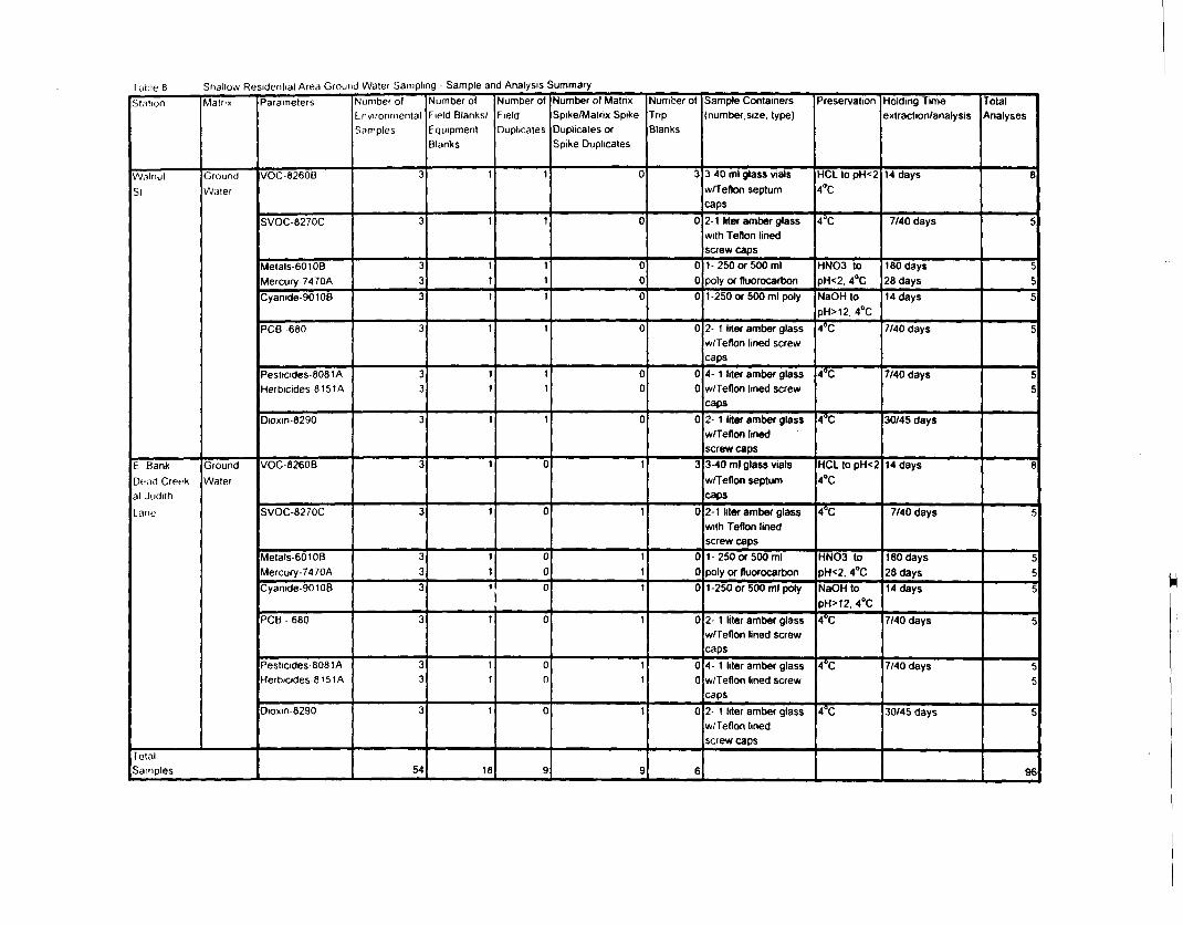
Table 8 Shallow Residential Area Ground Water Sampling Sample and Analysis SummarySt.ition
WalnutSi
E BankDund Creekat JudithLane
Matrix
GroundWater
GroundWater
TotalSamples
Parameters
VOC-8260B
SVOC-8270C
Metals-601 OBMercury-7470ACyanide-901 OB
PCB -680
Pesliades-8081AHerbicides 8151A
Dioxm-8290
VOC-8260B
SVOC-8270C
Metals-601 OBMercury-7470ACyanide-90106
PCB - 680
Pesticides-8081AHerbicides 8 151 A
Dioxm-8290
Number ofLrwiromnentalSamples
3
3
333
3
33
3
3
3
33
3
3
33
3
54
Number ofField Blanks/EquipmentBlanks
1
1
111
1
11
1
1
1
111
1
11
1
18
Number ofFieldDuplicates
1
1
111
1
11
1
0
0
000
0
00
0
9
Number of MatrixSpike/Matrix SpikeDuplicates orSpike Duplicates
0
0
000
0
00
0
1
1
111
1
11
1
9
Number ofTripBlanks
3
0
000
0
00
0
3
0
000
0
00
0
6
Sample Containers'number. size, type)
3-40 ml glass vialsw/Teflon septumcaps2-1 liter amber glasswith Teflon linedscrew caps1- 250 or 500 mlpoly or fluorocarbon1-250 or 500 ml poly
2- 1 liter amber glassw/Teflon lined screwcaps4- 1 liter amber glassw/Teflon lined screwcaps2- 1 liter amber glassw/Teflon linedscrew caps3-40 ml glass vialsw/Teflon septumcaps2-1 liter amber glasswith Teflon linedscrew caps1-250 or 500 mlpoly or fluorocarbon1-250 or 500 ml poly
2- 1 liter amber glassw/Teflon lined screwcaps4- 1 liter amber glassw/Teflon lined screwcaps2- 1 liter amber glassw/Teflon linedscrew caps
Preservation
HCL to pH<24"C
4^
HNO3 topH<2, 4°CNaOH topH>12. 4°C4°C
4°C
4°C
HCL to pH<24°C
4°C
HNO3 topH<2. 4°CNaOH topH>12. 4°C4°C
4°C
4°C
Holding Timeextraction/analysis
14 days
7/40 days
180 days28 days14 days
7/40 days
7/40 days
30/45 days
14 days
7/40 days
180 days28 days14 days
7/40 days
7/40 days
30/45 days
TotalAnalyses
8
5
555
5
55
8
C
c.
5
c
£
55
5
96
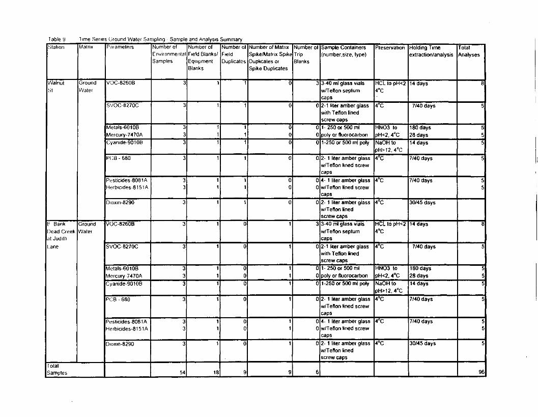
Table 9 Time Series Ground Water Sampling Sample and Analysis SummaryStation
Walnutst
E BankDead Creekat JudithI ane
Matrix
GroundWater
GroundWater
TotalSamples
Parameters
VOC-8260B
SVOC-8270C
Metals-60106Mercury-7470ACyanide-9010B
PCB - 680
Pesticides-8081 AHerbicides-8151 A
Dioxm-8290
VOC-8260B
SVOC-8270C
Metals-60108Mercury 7470ACyanide-90108
PCB - 680
Pesticides-8081 AHerbicides-81 51 A
Dioxm-8290
Number ofEnvironmentalSamples
3
3
333
3
33
3
3
3
333
3
33
3
54
Number ofField Blanks/EquipmentBlanks
1
1
111
1
11
1
1
1
111
1
11
1
18
Number ofFieldDuplicates
1
1
111
1
11
1
0
0
000
0
00
0
9
Number of MatrixSpike/Matrix SpikeDuplicates orSpike Duplicates
0
0
000
0
00
0
1
1
111
1
11
1
9
Number ofTripBlanks
3
0
000
0
00
0
3
0
000
0
00
0
6
Sample Containers(number.size, type)
3-40 ml glass vialsw/Teflon septumcaps2-1 liter amber glasswith Teflon linedscrew caps1-250 or 500 mlpoly or fluorocarbon1-250 or 500 ml poly
2- 1 liter amber glassw/Teflon lined screwcaps4- 1 liter amber glassw/Teflon lined screwcaps2- 1 liter amber glassw/Teflon linedscrew caps3-40 ml glass vialsw/Teflon septumcaps2-1 liter amber glasswith Teflon linedscrew caps1-250 or 500 mlpoly or fluorocarbon1-250 or 500 ml poly
2- 1 liter amber glassw/Teflon lined screwcaps4- 1 liter amber glassw/Teflon lined screwcaps2- 1 liter amber glassw/Teflon linedscrew caps
Preservation
HCL to pH<24°C
4°C
HNO3 topH<2. 4°CNaOH topH>12, 4°C4°C
4"C
4°C
HCL to pH<24°C
4°C
HNO3 topH<2, 4°CNaOH topH>12,4°C4°C
4°C
4°C
Holding Timeextraction/analysis
14 days
7/40 days
180 days28 days14 days
7/40 days
7/40 days
30/45 days
14 days
7/40 days
180 days28 days14 days
7/40 days
7/40 days
30/45 days
TotalAnalyses
8
5
555
5
55
8
5
555
5
5c
5
96
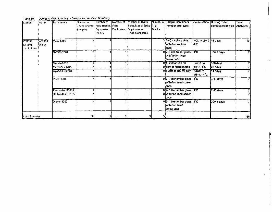
Table 10 Domestic Well Sampling - Sample and Analysis SummaryStation
WalnutSI andJudith Lane
Matrix
GroundWater
Total Samples
Parameters
VOC-8260
SVOC-8270
Metals-6010Mercury-7470ACyanide-9010B
PCB - 680
Pesticides-8081AHerbicides-8151 A
Dioxm-8290
Number ofEnvironmentalSamples
4
4
444
4
44
4
36
Number ofField Blanks/EquipmentBlanks
1
1
11
. 1
1
11
1
9
Number ofFieldDuplicates
1
1
111
1
11
1
9
Number of MatrixSpike/Matrix SpikeDuplicates orSpike Duplicates
1
1
111
1
11
1
9
Number ofTiipBlanks
3
0
000
0
00
0
3
Sample Containers(number, size, type)
3-40 ml glass vialsw/Teflon septumcaps2-1 liter amber glasswith Teflon linedscrew caps1-250 or 500 mlpoly or fluorocarbon1-250 or 500 ml poly
2- 1 liter amber glassw/Teflon lined screwcaps4- 1 liter amber glassw/Teflon lined screwcaps2- 1 liter amber glassw/Teflon linedscrew caps
Preservation
HCL to pH<24°C
4°C
HNO3 topH<2, 4°CNaOH topH>12, 4°C4°C
4°C
4°C
Holding Timeextraction/analysis
14 days
7/40 days
180 days28 days14 days
7/40 days
7/40 days
30/45 days
TotalAnalyses
10
7
777
7
77
7
66
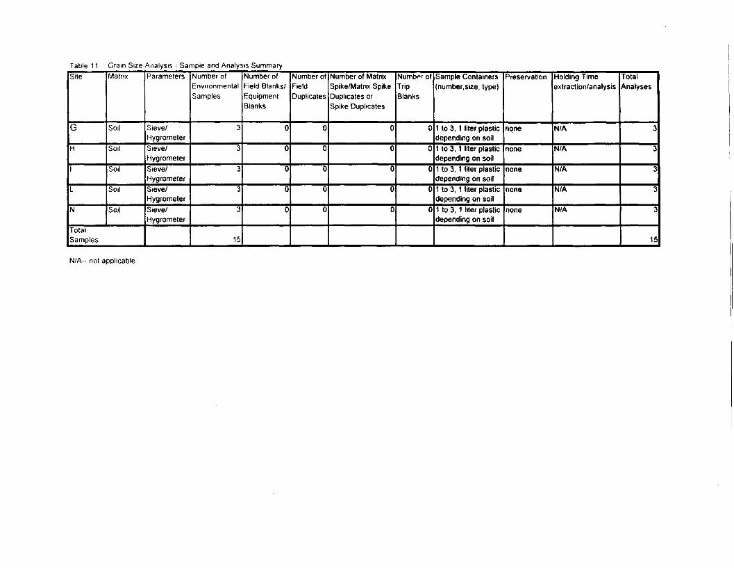
Table 11 Gram Size Analysis - Sample and Analysis SummarySite
G
H
I
L
N
Matrix
Soil
Soil
Soil
Soil
Soil
TotalSamples
Parameters
Sieve/HygrometerSieve/HygrometerSieve/HygrometerSieve/HygrometerSieve/Hygrometer
Number ofEnvironmentalSamples
3
3
3
3
3
15
Number ofField Blanks/EquipmentBlanks
0
0
0
0
0
Number ofFieldDuplicates
0
0
0
0
0
Number of MatrixSpike/Matrix SpikeDuplicates orSpike Duplicates
0
0
0
0
0
Number ofTripBlanks
0
0
0
0
0
Sample Containers(number. size, type)
1 to 3, 1 liter plasticdepending on soil1 to 3, 1 liter plasticdepending on soil1 to 3, 1 liter plasticdepending on soil1 to 3, 1 liter plasticdepending on soil1 to 3, 1 liter plasticdepending on soil
Preservation
none
none
none
none
none
Holding Timeextraction/analysis
N/A
N/A
N/A
N/A
N/A
TotalAnalyses
3
3
3
3
T
15
N/A—not applicable
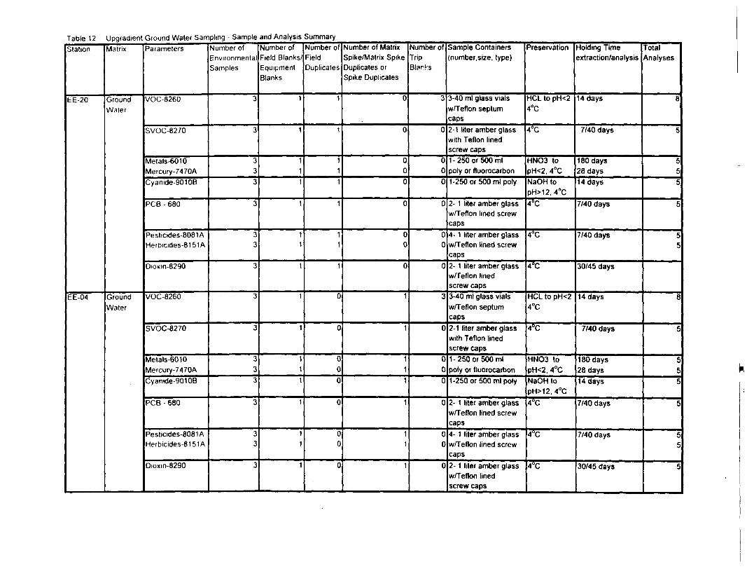
Table 12 Upgradient Ground Water Sampling - Sample and Analysis SummaryStation
EE-20
EE-04
Matrix
GroundWater
GroundWater
Parameters
VOC-8260
SVOC-8270
Metals-6010Mercury-7470ACyanide-90108
PCB - 680
Pesticides-8081 AHerbicides-8151 A
Dioxm-8290
VOC-8260
SVOC-8270
Metals-6010Mercury-7470ACyanide-90108
PCB - 680
Pesticides-8081 AHerbicides-81 51 A
Dioxm-8290
Number ofEnvironmentalSamples
3
3
333
3
33
3
3
3
333
3
33
3
Number ofField Blanks/EquipmentBlanks
1
1
111
1
11
1
1
1
111
1
11
1
Number ofFieldDuplicates
1
1
111
1
11
1
0
0
000
0
00
0
Number of MatrixSpike/Matrix SpikeDuplicates orSpike Duplicates
0
0
000
0
00
0
1
1
111
1
11
1
Number ofTripBlares
3
0
000
0
00
0
3
0
000
0
00
0
Sample Containers(number.size, type)
3-40 ml glass vialsw/Teflon septumcaps2-1 liter amber glasswith Teflon linedscrew caps1-250 or 500 mlpoly or fluorocarbon1-250 or 500 ml poly
2- 1 liter amber glassw/Teflon lined screwcaps4- 1 liter amber glassw/Teflon lined screwcaps2- 1 liter amber glassw/Teflon linedscrew caps3-40 ml glass vialsw/Teflon septumcaps2-1 liter amber glasswith Teflon linedscrew caps1-250 or 500 mlpoly or fluorocarbon1-250 or 500 ml poly
2- 1 liter amber glassw/Teflon lined screwcaps4- 1 liter amber glassw/Teflon lined screwcaps2- 1 liter amber glassw/Teflon linedscrew caps
Preservation
HCL to pH<24°C
4°C
HNO3 topH<2, 4°CNaOH topH>12. 4°C4°C
4°C
4°C
HCL to pH<24°C
4°C
HNO3 topH<2, 4°CNaOH topH>12. 4°C4°C
4°C
4°C
Holding Timeextraction/analysis
14 days
7/40 days
180 days28 days14 days
7/40 days
7/40 days
30/45 days
14 days
7/40 days
180 days28 days14 days
7/40 days
7/40 days
30/45 days
TotalAnalyses
8
5
555
5
f
c
8
f
e<j55
c•J
c
5
c
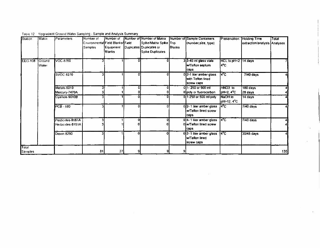
Table 12 Upgradient Ground Water Sampling • Sample and Analysis SummaryStation
EEG-108
Matrix
GroundWater
TotalSamples
Parameters
VOC-8260
SVOC8270
Metals-6010Mercury-7470ACyanide-90106
PCB - 680
Pesticides-8081AHerbicides-8151A
Dioxin 8290
Number ofEnvironmentalSamples
3
3
333
3
33
3
81
Number ofField Blanks/EquipmentBlanks
1
1
111
1
11
1
27
Number ofFieldDuplicates
0
0
000
0
00
0
9
Number of MatrixSpike/Matrix SpikeDuplicates orSpike Duplicates
0
0
000
0
00
0
9
Number ofTripBlanks
3
0
000
0
00
0
9
Sample Containers(number, size, type)
3-40 ml glass vialsw/Teflon septumcaps2-1 liter amber glasswith Teflon linedscrew caps1-250 or 500 mlpoly or fluorocarbon1-250 or 500 ml poly
2- 1 liter amber glassw/Teflon lined screwcaps4- 1 liter amber glassw/Teflon lined screwcaps2- 1 liter amber glassw/Teflon linedscrew caps
Preservation
HCL to pH<24°C
4°C
HNO3 topH<2, 4°CNaOH topH>12. 4°C4°C
4°C
4°C
Holding Timeextraction/analysis
14 days
7/40 days
180 days28 days14 days
7/40 days
7/40 days
30/45 days
TotalAnalyses
7
4
444
4
44
4
135
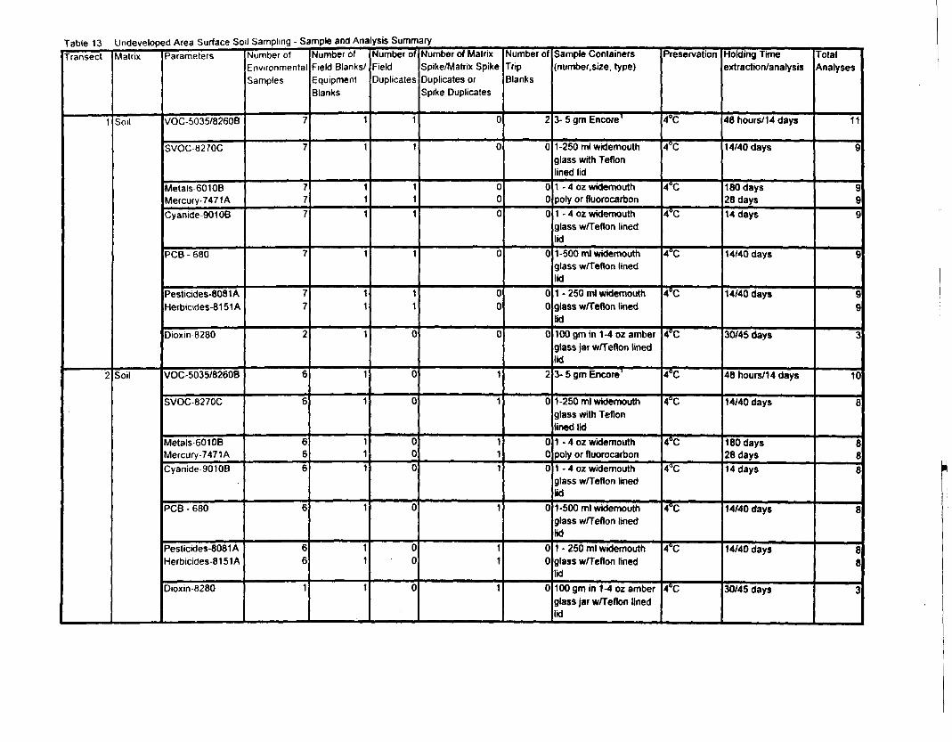
Table 13 Undeveloped Area Surface Soil Sampling - Sample and Analysis SummaryTransect
1
2
Matrix
Soil
Soil
Parameters
VOC-5035/8260B
SVOC-8270C
Metals-601 OBMercury-7471ACyanide-90106
PCB - 680
Pesticides-8081 AHerbicides-81 51 A
Dioxin 8280
VOC-5035/8260B
SVOC-8270C
Metals-60106Mercury-7471ACyanide 9010B
PCB - 680
Pesticides-8081 AHerbicides-81 51 A
Dioxin-8280
Number ofEnvironmentalSamples
7
7
777
7
77
2
6
6
666
6
66
1
Number ofField Blanks/EquipmentBlanks
1
1
111
1
11
1
1
1
111
1
11
1
Number ofFieldDuplicates
1
1
111
1
11
0
0
0
000
0
00
0
Number of MatrixSpike/Matrix SpikeDuplicates orSpike Duplicates
0
0
000
0
00
0
1
1
111
1
11
1
Number ofTripBlanks
2
0
000
0
00
0
2
0
000
0
00
0
Sample Containers(number.size, type)
3- 5 gm Encore1
1-250 ml widemouthglass with Teflonlined lid1 - 4 oz widemouthpoly or fluorocarbon1 - 4 02 widemouthglass w/Teflon linedlid1-500 ml widemouthglass w/Teflon linedlid1 - 250 ml widemouthglass w/Teflon linedlidlOOgmin 1-4 oz amberglass jar w/Teflon linedlid3- 5 gm Encore1
1-250 ml widemouthglass with Teflonlined lid1 - 4 oz widemouthpoly or fluorocarbon1 - 4 oz widemouthglass w/Teflon linedlid1-500 ml widemouthglass w/Teflon linedlid1 - 250 ml widemouthglass w/Teflon linedlid100 gm in 1-4 oz amberglass jar w/Teflon linedlid
Preservation
4°C
4°C
4°C
4°C
4^
4°C
4CC
4°C
4°C
4°C
4°C
4°C
4°C
4°C
Holding Timeextraction/analysis
48 hours/14 days
14/40 days
180 days28 days14 days
14/40 days
14/40 days
30/45 days
48 hours/14 days
14/40 days
180 days28 days14 days
14/40 days
14/40 days
30/45 days
TotalAnalyses
11
9
999
9
99
3
10
8
888
8
88
3
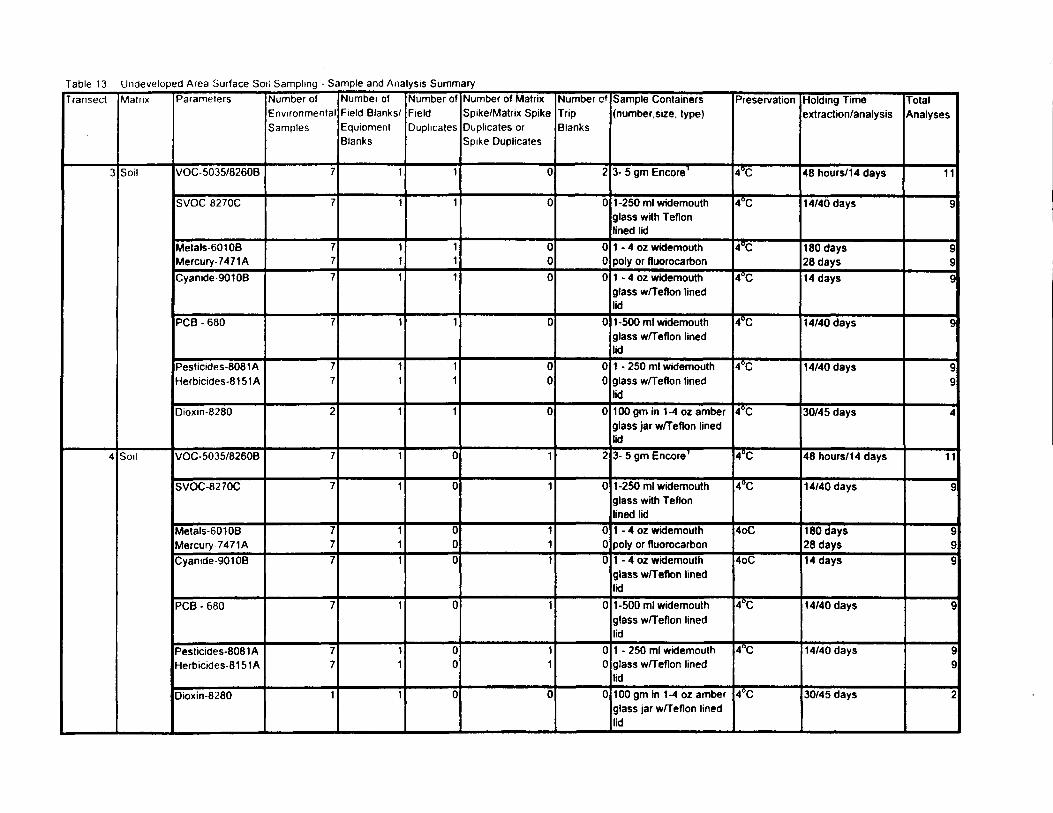
Table 13 Undeveloped Area Surface Soil Sampling - Sample and Analysis SummaryTransect
3
4
Matrix
Soil
Soil
Parameters
VOC-5035/8260B
SVOC-8270C
Metals 601 OBMercury-7471ACyanide 9010B
PCB - 680
Pesticides-8081AHerbicides-81 51 A
Dioxin-8280
VOC-5035/8260B
SVOC-8270C
Metals-60108Mercury 7471ACyanide 9010B
PCB - 680
Pesticides-8081 AHerbicides-81 51 A
Dioxin-8280
Number ofEnvironmentalSamples
7
7
777
7
77
2
7
7
777
7
77
1
Number ofField Blanks/EquipmentBlanks
1
1
111
1
11
1
1
1
111
1
11
1
Number ofFieldDuplicates
1
1
111
1
11
1
0
0
000
0
00
0
Number of MatrixSpike/Matrix SpikeDuplicates orSpike Duplicates
0
0
000
0
00
0
1
1
111
1
11
0
Number ofTripBlanks
2
0
000
0
00
0
2
0
000
0
00
0
Sample Containers(number.size. type)
3- 5 gm Encore1
1-250 ml widemouthglass with Teflonlined lid1 - 4 oz widemouthpoly or fluorocarbon1 - 4 oz widemouthglass w/Teflon linedlid1-500 ml widemouthglass w/Teflon linedlid1 - 250 ml widemouthglass w/Teflon linedlid100 gm in 1-4 oz amberglass jar w/Teflon linedlid3- 5 gm Encore1
1-250 ml widemouthglass with Teflonlined lid1 - 4 oz widemouthpoly or fluorocarbon1 - 4 oz widemouthglass w/Teflon linedlid1-500 ml widemouthglass w/Teflon linedlid1 - 250 ml widemouthglass w/Teflon linedlid100 gm in 1-4 oz amberglass jar w/Teflon linedlid
Preservation
4°C
4°C
4°C
4°C
4°C
4°C
4°C
4°C
4°C
4oC
4oC
4°C
4°C
4°C
Holding Timeextraction/analysis
48 hours/1 4 days
14/40 days
180 days28 days14 days
14/40 days
14/40 days
30/45 days
48 hours/14 days
14/40 days
180 days28 days14 days
14/40 days
14/40 days
30/45 days
TotalAnalyses
11
9
999
9
99
4
11
9
999
g
99
2
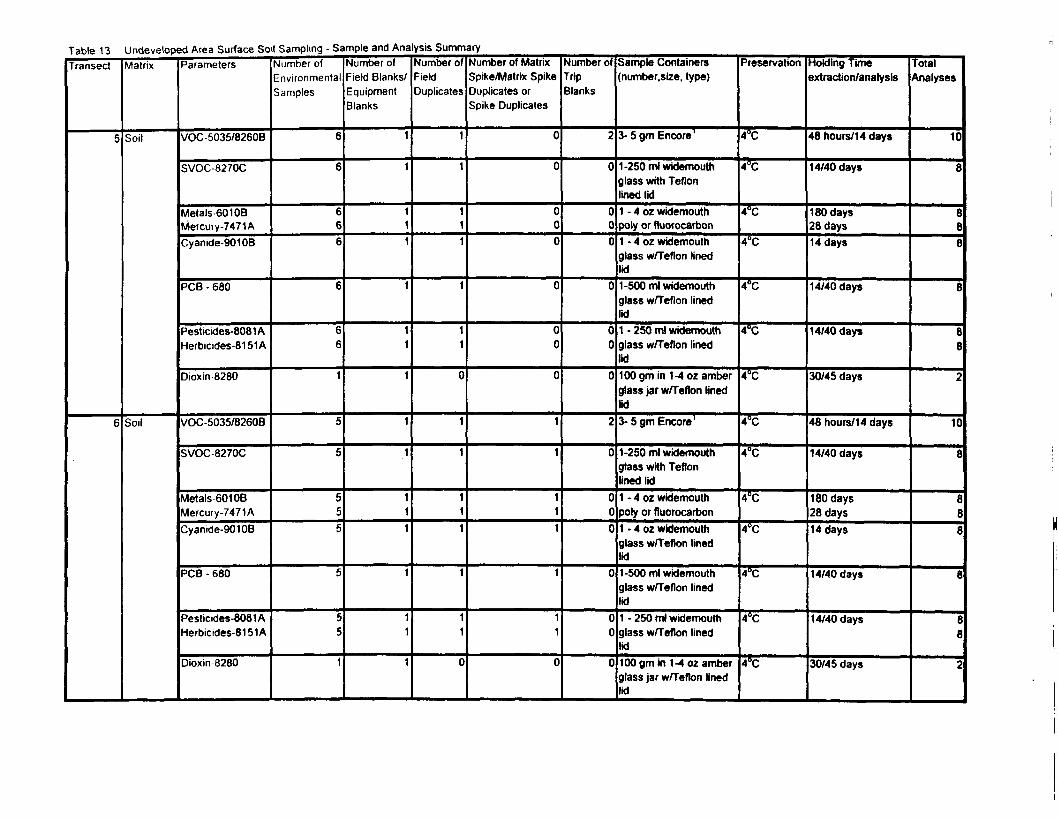
Table 13 Undeveloped Area Surface Soil Sampling - Sample and Analysis SummaryTransect
5
6
Matrix
Soil
Soil
Parameters
VOC-5035/8260B
SVOC-8270C
Metals-60108Mercury-7471 ACyanide-90106
PCB - 680
Pesticides-8081 AHerbicides-81 51 A
Dioxin 8280
VOC-5035/8260B
SVOC-8270C
Metals 6010BMercury-7471ACyanide-90108
PCB - 680
Pesticides-8081 AHerbicides-81 51 A
Dioxin 8280
Number ofEnvironmentalSamples
6
6
666
6
66
1
5
5
555
5
55
1
Number ofField Blanks/EquipmentBlanks
1
1
111
1
11
1
1
1
111
1
11
1
Number ofFieldDuplicates
1
1
111
1
11
0
1
1
111
1
11
0
Number of MatrixSpike/Matrix SpikeDuplicates orSpike Duplicates
0
0
000
0
00
0
1
1
111
1
11
0
Number ofTripBlanks
2
0
000
0
00
0
2
0
000
0
00
0
Sample Containers(number.size, type)
3- 5 gm Encore1
1-250 ml widemouthglass with Teflonlined lid1 - 4 oz widemouthpoly or fluorocarbon1 - 4 oz widemouthglass w/Teflon linedlid1 -500 ml widemouthglass w/Teflon linedlid1 - 250 ml widemouthglass w/Teflon linedlid100 gm in 1-4 oz amberglass jar w/Teflon linedlid3- 5 gm Encore1
1-250 ml widemouthglass with TeflonHnedlid1 • 4 oz widemouthpoly or fluorocarbon1 - 4 oz widemouthglass w/Teflon linedlid1-500 ml widemouthglass w/Teflon linedlid1 - 250 ml widemouthglass w/Teflon linedlid100 gm in 1-4 oz amberglass jar w/Teflon linedlid
Preservation
4°C
4°C
4°C
4°C
4°C
4°C
4°C
4°C
4°C
4°C
4°C
4°C
4°C
4°C
extraction/analysis
48 hours/14 days
14/40 days
180 days28 days14 days
14/40 days
14/40 days
30/45 days
48 hours/14 days
14/40 days
180 days28 days14 days
14/40 days
14/40 days
30/45 days
TotalAnalyses
10
8
888
8
88
2
10
8
888
8
88
2
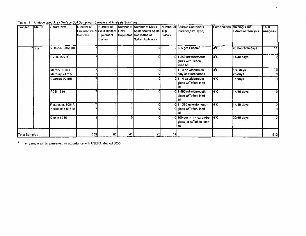
Table 13 Undeveloped Area Surface Soil Sampling - Sample and Analysis SummaryTransect
7
Matrix
Soil
Total Samples
Parameters
VOC-5035/8260B
SVOC-8270C
Metals-601 OBMercury-7471 ACyanide-90108
PCB - 680
Pesticides-8081 AHerbicides-81 51 A
Dioxm-8280
Number ofEnvironmentalSamples
7
7
777
7
77
1
369
Number ofField Blanks/EquipmentBlanks
1
1
111
1
11
1
63
Number ofFieldDuplicates
1
1
111
1
11
0
41
Number of MatrixSpike/Matrix SpikeDuplicates orSpike Duplicates
0
0
000
0
00
0
25
Number ofTripBlanks
2
0
000
0
00
0
14
Sample Containers(number.size, type)
3- 5 gm Encore1
1-250 ml wkJemouthglass with Teflonlined lid1 - A oz widemouthpoly or fluorocarbon1 - 4 oz widemouthglass w/Teflon linedlid1-500 ml widemouthglass w/Teflon linedlid1 - 250 ml widemouthglass w/Teflon linedlid100 gm in 1-4 oz amberglass jar w/Teflon linedlid
Preservation
4°C
4°C
4°C
4°C
4°C
4°C
4°C
Holding Timeextraction/analysis
48 hours/14 days
14/40 days
180 days28 days14 days
14/40 days
14/40 days
30/45 days
TotalAnalyses
11
9
999
9
99
2
512
or sample will be preserved in accordance with USEPA Method 5035
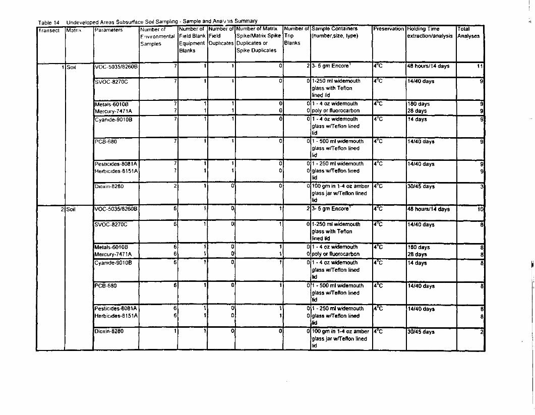
Table 14 Undeveloped Areas Subsurface Soil SamplingTransect
1
2
Matrix
Soil
Soil
Parameters
VOC-5035/8260B
SVOC 8270C
Metals-60108Mercury-7471 ACyanide-90108
PCB-680
Pesticides-8081 AHerbicides-8151 A
Dioxin-8280
VOC-5035/8260B
SVOC-8270C
Metals-60108Mercury-7471 ACyanide-90108
PCB-680
Pesticides-8081AHerbicides-81 51 A
Dioxin-8280
Number ofEnvironmentalSamples
7
7
777
7
77
2
6
6
666
6
66
1
- Sample and Anav >is Summary
Field BlankEquipmentBlanks
1
1
111
1
11
1
1
1
111
1
11
1
Number ofFieldDuplicates
1
1
111
1
11
0
0
0
000
0
00
0
Number of MatrixSpike/Matrix SpikeDuplicates orSpike Duplicates
0
000
0
00
0
1
1
111
1
11
0
Number ofTripBlanks
0
000
0
00
0
2
0
000
0
00
0
Sample Containers(number, size, type)
3- 5 gm Encore1
1-250 ml widemouthglass with Teflonlined lid1 - 4 oz widemouthpoly or fluorocarfaon1 - 4 oz widemouthglass w/Teflon linedlid1 - 500 ml widemouthglass w/Teflon linedlid1 - 250 ml widemouthglass w/Teflon linedlid100 gm in 1-4 oz amberglass jar w/Teflon linedlid3- 5 gm Encore1
1-250 ml widemouthglass with Teflonlined lid1 - 4 oz widemouthpoly or fluorocarbon1 - 4 oz widemouthglass w/Teflon linedlid1 - 500 ml widemouthglass w/Teflon linedlid1 - 250 ml widemouthglass w/Teflon linedlid100 gm in 1-4 oz amberglass jar w/Teflon linedlid
Preservation
4°C
4°C
4°C
4°C
4°C
4*C
4°C
4°C
4°C
4°C
4°C
4°C
4°C
4°C
Holding Timeextraction/analysis
48 hours/14 days
14/40 days
180 days28 days14 days
14/40 days
14/40 days
30/45 days
48 hours/14 days
14/40 days
180 days28 days14 days
14/40 days
14/40 days
30/45 days
Analyses
11
9
999
9
99
3
10
8
888
8
88
2
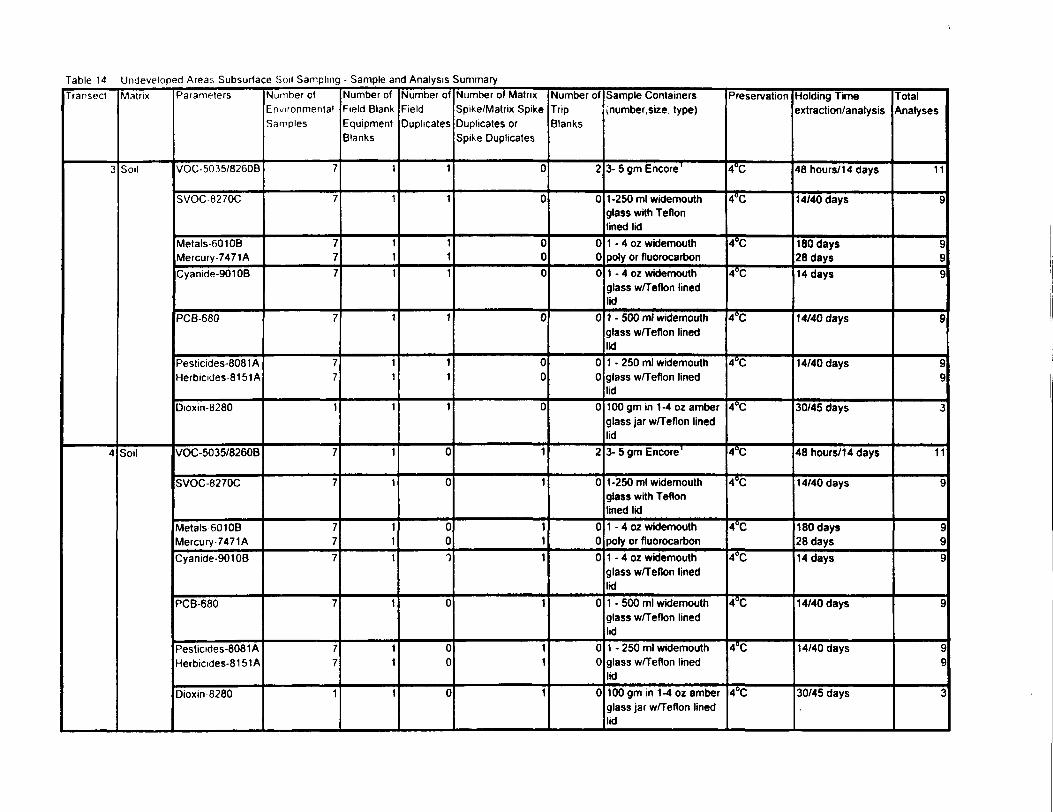
Table 14 Undeveloped Areas Subsurface Soil Sampling - Sample and Analysis SummaryTransect
3
4
Matrix
Soil
Soil
Parameters
VOC-5035/8260B
SVOC-8270C
Metals-601 OBMercury-7471ACyanide-90108
PCB-680
Pesticides-8081AHerbicides-8151A
Dioxin-8280
VOC-5035/8260B
SVOC-8270C
Metals 6010BMercury 7471ACyanide-90108
PCB-680
Pesticides-8081 AHerbicides-81 51 A
Dioxin 8280
Number ofEnvironmentalSamples
7
7
777
7
77
1
7
7
777
7
77
1
Number ofField BlankEquipmentBlanks
1
1
111
1
11
1
1
1
111
1
11
1
Number ofFieldDuplicates
1
1
111
1
11
1
0
0
001
0
00
0
Number of MatrixSpike/Matrix SpikeDuplicates orSpike Duplicates
0
0
000
0
00
0
1
1
111
1
11
1
Number ofTripBlanks
2
0
000
0
00
0
2
0
000
0
00
0
Sample Containersjnumber.size, type)
3- 5 gm Encore1
1-250 ml widemouthglass with Teflonlined lid1 - 4 oz widemouthpoly or fluorocarbon1 - 4 oz widemouthglass w/Teflon linedlid1 - 500 ml widemouthglass w/Teflon linedlid1 - 250 ml widemouthglass w/Teflon linedlid100 gm in 1-4 oz amberglass jar w/Teflon linedlid3- 5 gm Encore1
1-250 ml widemouthglass with Teflonlined lid1 - 4 oz widemouthpoly or fluorocarbon1 - 4 oz widemouthglass w/Teflon linedlid1 - 500 ml widemouthglass w/Teflon linedlid1 - 250 ml widemouthglass w/Teflon linedlid100 gm in 1-4 oz amberglass jar w/Teflon linedlid
Preservation
4°C
4°C
4°C
4°C
4^
4°C
4°C
4°C
4^
4°C
4°C
4°C
4°C
4°C
Holding Timeextraction/analysis
48 hours/14 days
14/40 days
180 days28 days14 days
14/40 days
14/40 days
30/45 days
48 hours/1 4 days
14/40 days
180 days28 days14 days
14/40 days
14/40 days
30/45 days
TotalAnalyses
11
9
999
9
99
3
11
9
999
9
99
i
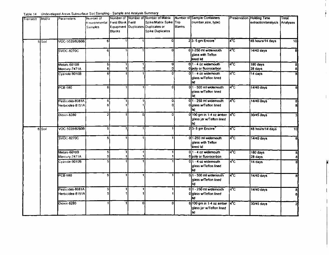
Table 14 Undeveloped Areas Subsurface Soil Sampling - Sample and Analysis SummaryTransect Matrix Parameters Number nf Number nf Nnmhor nf Mnmhar nf Main- M..mh~,~«o —— .- /•<--•-. —— ~
5
6
Matrix
Soil
Soil
Parameters
VOC-5035/8260B
SVOC-8270C
Metals-60108Mercury-7471ACyanide-90108
PCB 680
Pesticides-8081AHerbicides-8151A
Dioxm-8280
VOC 5035/82608
SVOC-8270C
Metals-601 OBMercury-7471ACyanide-90108
PCB-680
Pesticides-8081 AHerbicides-81 51A
Dioxm-8280
Number ofEnvironmentalSamples
6
6
666
6
66
2
5
5
555
5
55
1
Number ofField BlankEquipmentBlanks
1
1
111
1
11
1
1
1
111
1
11
1
Number ofFieldDuplicates
1
1
111
1
11
0
1
1
111
1
11
0
Number of MatrixSpike/Matrix SpikeDuplicates orSpike Duplicates
0
0
000
0
00
0
1
1
111
1
11
0
Number ofTripBlanks
2
0
000
0
00
0
2
0
000
0
00
0
Sample Containers(number, size, type)
3- 5 gm Encore1
1-250 ml widemouthglass with Teflonlined lid1 - 4 oz widemouthpoly or fluorocarbon1 - 4 oz widemouthglass w/Teflon linedlid1 - 500 ml widemouthglass w/Teflon linedlid1 - 250 ml widemouthglass w/Teflon linedlid100 gm in 1-4 oz amberglass jar w/Teflon linedlid3- 5 gm Encore'
1-250 ml widemouthglass with Teflonlined lid1 - 4 oz widemouthpoly or fluorocarbon1 - 4 oz widemouthglass w/Teflon linedlid1 - 500 ml widemouthglass w/Teflon linedlid1 - 250 ml widemouthglass w/Teflon linedlid100 gm in 1-4 oz amberglass jar w/Teflon linedlid
Preservation
4°C
4°C
4°C
4°C
4°C
4°C
4°C
4°C
4CC
4°C
4°C
4°C
4°C
4°C
Holding Timeextraction/analysis
48 hours/14 days
14/40 days
180 days28 days14 days
14/40 days
14/40 days
30/45 days
48 hours/14 days
14/40 days
180 days28 days14 days
14/40 days
14/40 days
30/45 days
TotalAnalyses
10
8
888
8
88
2
10
8
888
8
88
2
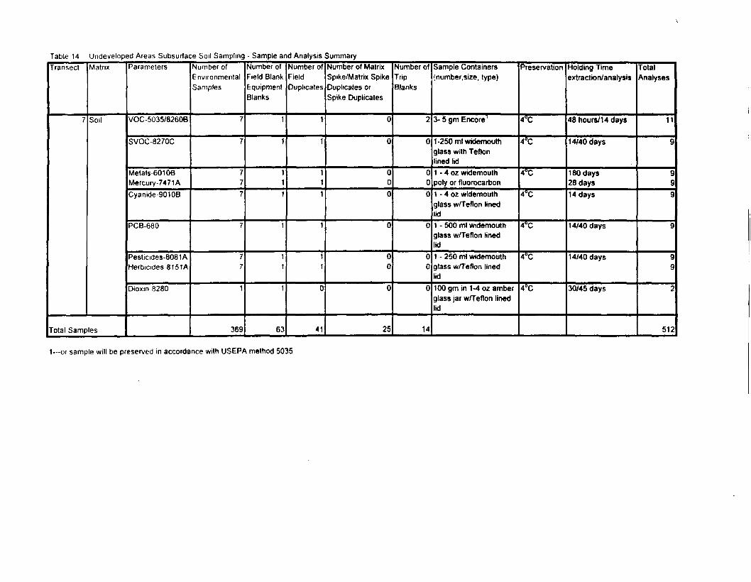
Table 14 Undeveloped Areas Subsurface Soil Sampling - Sample and Analysis SummaryTransect
7
Matrix
Soil
Total Samples
Parameters
VOC-5035/8260B
SVOC8270C
Metals 601 OBMercury-7471 ACyanide-90108
PCB-680
Pesticides-8081AHerbicides-81 51 A
Dioxin 8280
Number ofEnvironmentalSamples
7
7
777
7
77
1
369
Number ofField BlankEquipmentBlanks
1
1
111
1
11
1
63
Number ofFieldDuplicates
1
1
111
1
11
0
41
Number of MatrixSpike/Matrix SpikeDuplicates orSpike Duplicates
0
0
000
0
00
0
25
Number ofTripBlanks
2
0
000
0
00
0
14
Sample Containers(number, size, type)
3- 5 gm Encore1
1-250 ml widemouthglass with Teflonlined lid1 - 4 oz widemouthpoly or fluorocarfaon1 - 4 oz widemouthglass w/Teflon linedlid1 - 500 ml widemouthglass w/Teflon linedlid1 - 250 ml widemouthglass w/Teflon linedlid100 gm in 1-4 oz amberglass jar wfTeflon linedlid
Preservation
4°C
4°C
4°C
4°C
4°C
4°C
4°C
Holding Timeextraction/analysis
48 hours/14 days
14/40 days
180 days28 days14 days
14/40 days
14/40 days
30/45 days
TotalAnalyses
11
9
999
9
99
2
512
1—ot sample will be preserved in accordance with USEPA method 5035
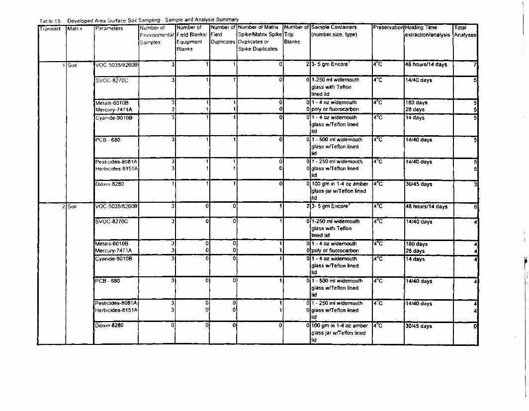
Table 15 Developed Area Surface Soil Sampling - Sample and Analysis SummaryTransect
1
2
Matrix
Soil
Soil
Parameters
VOC 5035/8260B
SVOC-8270C
Metals-60108Mercury-7471ACyanide-90108
PCB 680
Pesticides-8081 AHerbicides-8151A
Dioxin-8280
VOC-5035/8260B
SVOC-8270C
Metals-60106Mercury-7471ACyanide-90108
PCB - 680
Pesticides-8081 AHerbicides-8151A
Dioxin-8280
Number ofEnvironmentalSamples
3
3
333
3
33
1
3
3
333
3
33
0
Number ofField Blanks/EquipmentBlanks
1
1
111
1
11
1
0
0
000
0
00
0
Number ofFieldDuplicates
1
1
111
1
11
1
0
0
000
0
00
0
Number of MatrixSpike/Matrix SpikeDuplicates orSpike Duplicates
0
0
000
0
00
0
1
1
111
1
11
0
Number ofTripBlanks
2
0
000
0
00
0
2
0
000
0
00
0
Sample Containers(number.size, type)
3- 5 gm Encore1
1-250 ml widemouthglass with Teflonlined lid1 - 4 oz widemouthpoly or fluorocarbon1 - 4 oz widemouthglass w/Teflon linedlid1 - 500 ml widemouthglass w/Teflon linedlid1 - 250 ml widemouthglass w/Teflon linedlid100gm in 1-4 oz amberglass jar w/Teflon linedlid3- 5 gm Encore1
1-250 ml widemouthglass with Teflonlined lid1 - 4 oz widemouthpoly or fluorocarbon1 - 4 oz widemouthglass w/Teflon linedlid1 - 500 ml widemouthglass w/Teflon linedlid1 - 250 ml widemouthglass w/Teflon linedlid100 gm in 1-4 oz amberglass jar w/Teflon linedlid
Preservation
4"C —————
4°C
4°C
4°C
4°C
4°C
4°C
4°C
4°C
4°C
4°C
4°C
4°C
4°C
Holding Timeextraction/analysis
48 hours/14 days
14/40 days
180 days28 days14 days
14/40 days
14/40 days
30/45 days
48 hours/14 days
14/40 days
180 days28 days14 days
14/40 days
14/40 days
30/45 days
TotalAnalyses
7
5
555
5
55
3
6
4
444
4
44
0
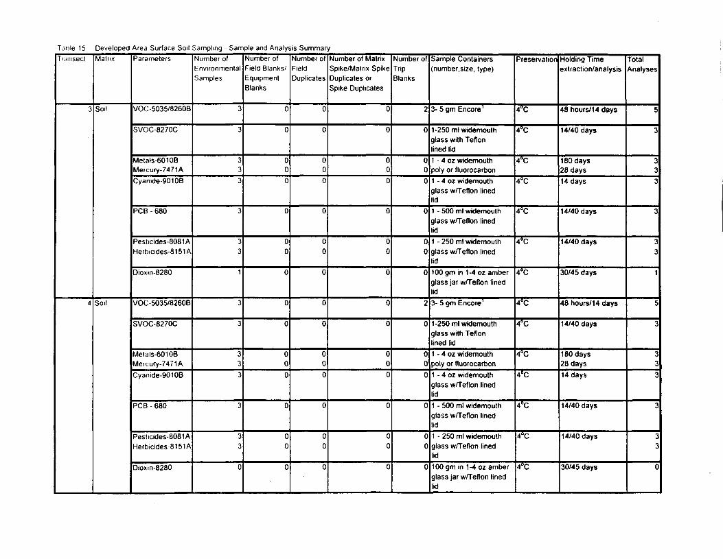
Taole 15 Developed Area Surface Soil Sampling - Sample and Analysis SummaryTransect
3
4
Matrix
Soil
Soil
Parameters
VOC-5035/8260B
SVOC-8270C
Metals-601 OBMercury-7471 ACyamde-9010B
PCB - 680
Pesticides-8081AHerbicides-8151A
Dioxm-8280
VOC-5035/8260B
SVOC-8270C
Metals-60106Mercury-7471ACyanide-9010B
PCB - 680
Pesticides-8081AHerbicides-81 51 A
Dioxm-8280
Number ofEnvironmentalSamples
3
3
333
3
33
1
3
3
333
3
33
0
Number ofField Blanks/EquipmentBlanks
0
0
000
0
00
0
0
0
000
0
00
0
Number ofFieldDuplicates
0
0
000
0
00
0
0
0
000
0
00
0
Number of MatrixSpike/Matrix SpikeDuplicates orSpike Duplicates
0
0
000
0
00
0
0
0
000
0
00
0
Number ofTripBlanks
2
0
000
0
00
0
2
0
000
0
00
0
Sample Containers(number, size, type)
3- 5 gm Encore1
1-250 ml widemouthglass with Teflonlined lid1 - 4 oz widemouthpoly or fluorocarbon1 - 4 oz widemouthglass w/Teflon linedlid1 - 500 ml widemouthglass w/Teflon linedlid1 - 250 ml widemouthglass w/Teflon linedlid100 gm in 1-4 oz amberglass jar w/Teflon linedlid3- 5 gm Encore1
1-250 ml widemouthglass with Teflonlined lid1 - 4 oz widemouthpoly or fluorocarbon1 - 4 oz widemouthglass w/Teflon linedlid1 - 500 ml widemouthglass w/Teflon linedlid1 - 250 ml widemouthglass w/Teflon linedlid100 gm in 1-4 oz amberglass jar w/Teflon linedlid
Preservation
4°C
4°C
4°C
4°C
4°C
4°C
4°C
4°C
4°C
4°C
4°C
4°C
4°C
4°C
Holding Timeextraction/analysis
48 hours/14 days
14/40 days
180 days28 days14 days
14/40 days
14/40 days
30/45 days
48 hours/1 4 days
14/40 days
180 days28 days14 days
14/40 days
14/40 days
30/45 days
TotalAnalyses
5
3
333
3
33
1
5
3
333
3
22
0
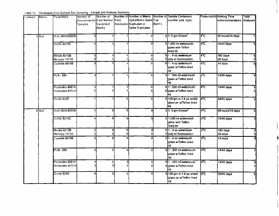
I able 15 Developed Area Surface Soil Sampling - Sample and Analysis SummaryIransect
5
6
Matrix
Soil
Soil
Parameters
VOC-5035/8260B
SVOC-8270C
Metals-601 OBMercury-7471 ACyanide-90108
PCB - 680
Pesticides-8081 AHerbicides-81 51 A
Dioxm-8280
VOC-5035/8260B
SVOC-8270C
Metals-60108Mercury-7471ACyanide-90108
PCB - 680
Pesticides-8081AHerbicides-81 51 A
Dioxm-8280
Number ofEnvironmentalSamples
3
3
333
3
33
1
3
3
333
3
33
0
Number ofField Blanks/EquipmentBlanks
1
1
111
1
11
1
0
0
000
0
00
0
Number ofFieldDuplicates
1
1
111
1
11
0
0
0
000
0
00
0
Number of MatrixSpike/Matrix SpikeDuplicates orSpike Duplicates
0
0
000
0
00
0
0
0
000
0
00
0
Number ofTripBlanks
2
0
000
0
00
0
2
0
000
0
00
0
Sample Containersinumber.size, type)
3- 5 gm Encore1
1-250 ml widemouthglass with Teflonlined lid1 - 4 oz widemouthpoly or fluorocarbon1 - 4 oz widemouthglass w/Teflon linedlid1 - 500 ml widemouthglass w/Teflon linedlid1 - 250 ml widemouthglass w/Teflon linedlid100 gm in 1-4 oz amberglass jar w/Teflon linedlid3- 5 gm Encore1
1-250 ml widemouthglass with Teflonlined lid1 - 4 oz widemouthpoly or fluorocarbon1 - 4 oz widemouthglass w/Teflon linedlid1 - 500 ml widemouthglass w/Teflon linedlid1 - 250 ml widemouthglass w/Teflon linedlid100 gm in 1-4 oz amberglass jar w/Teflon linedlid
Preservation
4°C
4°C
4°C
4°C
4°C
4°C
4°C
4°C
4°C
4°C
4°C
4°C
4°C
4°C
Holding Timeextraction/analysis
48 hours/14 days
14/40 days
180 days28 days14 days
14/40 days
14/40 days
30/45 days
48 hours/14 days
14/40 days
180 days28 days14 days
14/40 days
14/40 days
30/45 days
TotalAnalyses
7
5
555
5
55
2
5
•:
i•3
T
*
0
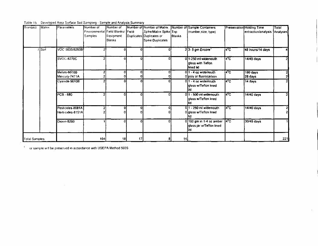
Table 15 Developed Area Surface Soil Sampling - Sample and Analysis SummaryTransect
7
Matrix
Soil
Total Samples
Parameters
VOC 5035/8260B
SVOC-8270C
Metals-60106Mercury-7471 ACyanide-901 OB
PCB - 680
Pesticides-8081AHerbicides-8151 A
Dioxm-8280
Number ofEnvironmentalSamples
2
2
222
2
22
1
164
Number ofField Blanks/EquipmentBlanks
0
0
000
0
00
0
18
Number ofFieldDuplicates
0
0
000
0
00
0
17
Number of MatrixSpike/Matrix SpikeDuplicates orSpike Duplicates
0
0
000
0
00
0
8
Number ofTripBlanks
2
0
000
0
00
0
14
Sample Containers(number.size, type)
3- 5 gm Encore1
1-250 ml widemouthglass with Teflonlined lid1 - 4 oz widemouthpoly or fluorocarbon1 - 4 oz widemouthglass w/Teflon linedlid1 - 500 ml widemouthglass w/Teflon linedlid1 - 250 ml widemouthglass w/Teflon linedlid100 gm in 1-4 oz amberglass jar w/Teflon linedlid
Preservation
4°C
4°C
4°C
4°C
4°C
4°C
4°C
Holding Timeextraction/analysis
48 hours/14 days
14/40 days
180 days28 days14 days
14/40 days
14/40 days
30/45 days
TotalAnalyses
4
2
222
2
22
1
221
or sample will be preserved in accordance with USEPA Method 5035
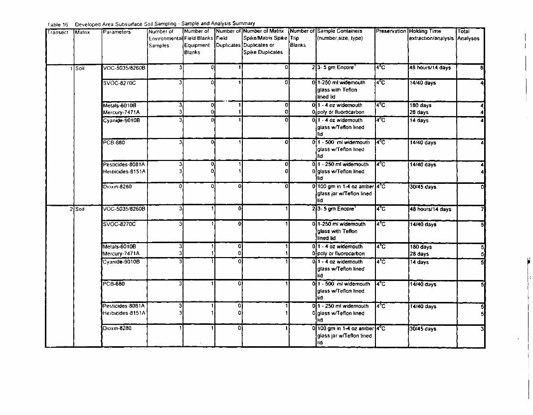
Table 16 Developed Area Subsurface Soil Sampling - Sample and Analysis SummaryTransect
1
2
Matrix
Soil
Soil
Parameters
VOC-5035/8260B
SVOC-8270C
Metals-601 OBMercury-7471ACyanide-9010B
PCB-680
Pesticides-8081AHerbicides-81 51 A
Dioxin-8280
VOC-5035/8260B
SVOC-8270C
Metals-601 OBMercury-7471ACyanide-90106
PCB-680
Pesticides-8081 AHeibicides-8151A
Dioxin-8280
Number ofEnvironmentalSamples
3
3
333
3
33
0
3
3
333
3
33
1
Number ofField BlanksEquipmentBlanks
0
0
000
0
00
0
1
1
111
1
11
1
Number ofFieldDuplicates
1
1
111
1
11
0
0
0
000
0
00
0
Number of MatrixSpike/Matrix SpikeDuplicates orSpike Duplicates
0
0
000
0
00
0
1
1
111
1
11
1
Number ofTripBlanks
2
0
000
0
00
0
2
0
000
0
00
0
Sample Containers(number.size, type)
3- 5 gm Encore1
1-250 ml widemouthglass with Teflonlined lid1 - 4 oz widemouthpoly or fluorocarbon1 - 4 oz widemouthglass w/Teflon linedlid1 - 500 ml widemouthglass w/Teflon linedlid1 - 250 ml widemouthglass w/Teflon linedlid100 gm in 1-4 oz amberglass jar w/Teflon linedlid3- 5 gm Encore1
1-250 ml widemouthglass with Teflonlined lid1 - 4 oz widemouthpoly or fluorocarbon1 - 4 oz widemouthglass w/Teflon linedlid1 - 500 ml widemouthglass w/Teflon linedlid1 - 250 ml widemouthglass w/Teflon linedlid100 gm in 1-4 oz amberglass jar w/Teflon linedlid
Preservation
4°C
4°C
4°C
4°C
4°C
4°C
4°C
4°C
4°C
4°C
4°C
4°C
4°C
4°C
Holding Timeextraction/analysis
48 hours/1 4 days
14/40 days
180 days28 days14 days
14/40 days
14/40 days
30/45 days
48 hours/1 4 days
14/40 days
180 days28 days14 days
14/40 days
14/40 days
30/45 days
TotalAnalyses
6
4
444
4
44
0
7
5
cK
5
5
55
3
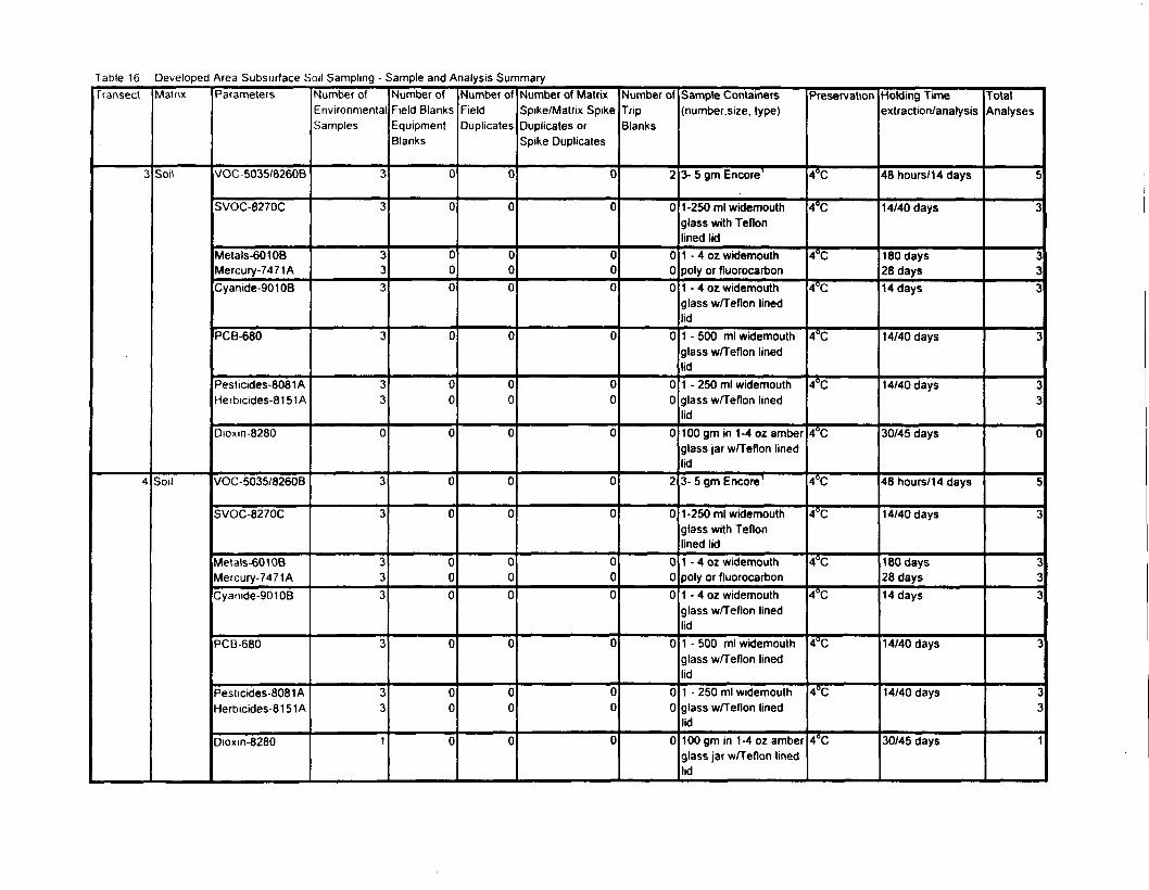
Table 16 Developed Area Subsurface Soil Sampling - Sample and Analysis SummaryTransect
3
4
Matrix
Soil
Soil
Parameters
VOC-5035/8260B
SVOC-8270C
Metals-60108Mercury-7471 ACyanide-90106
PCB-680
Pesticides-8081 AHerbicides-81 51 A
Dioxm-8280
VOC-5035/8260B
SVOC-8270C
Metals-601 OBMercury-7471ACyanide-90108
PCB-680
Pesticides-8081AHerbicides-8151A
Dioxm-8280
Number ofEnvironmentalSamples
3
3
333
3
33
0
3
3
333
3
33
1
Number ofField BlanksEquipmentBlanks
0
0
000
0
00
0
0
0
000
0
00
0
Number ofFieldDuplicates
0
0
000
0
00
0
0
0
000
0
00
0
Number of MatrixSpike/Matrix SpikeDuplicates orSpike Duplicates
0
0
000
0
00
0
0
0
000
0
00
0
Number ofTripBlanks
2
0
000
0
00
0
2
0
000
0
00
0
Sample Containers(number.size, type)
3- 5 gm Encore1
1-250 ml widemouthglass with Teflonlined lid1 - 4 oz widemouthpoly or fluorocarbon1 - 4 oz widemouthglass w/Teflon linedlid1 - 500 ml widemouthglass w/Teflon linedlid1 - 250 ml widemouthglass w/Teflon linedlid1 00 gm in 1-4 oz amberglass jar w/Teflon linedlid3- 5 gm Encore1
1-250 ml widemouthglass with Teflonlined lid1 - 4 oz widemouthpoly or fluorocarbon1 - 4 oz widemouthglass w/Teflon linedlid1 - 500 ml widemouthglass w/Teflon linedlid1 - 250 ml widemouthglass w/Teflon linedlid100 gm in 1-4 oz amberglass jar w/Teflon linedlid
Preservation
4°C
4°C
4°C
4°C
4°C
4"C
4°C
4°C
4°C
4°C
4°C
4°C
4°C
4°C
Holding Timeextraction/analysis
48 hours/14 days
14/40 days
180 days28 days14 days
14/40 days
14/40 days
30/45 days
48 hours/14 days
14/40 days
180 days28 days14 days
14/40 days
14/40 days
30/45 days
TotalAnalyses
5
3
333
3
33
0
5
3
333
3
23
1

7 able 16 Developed Area Subsurface Soil Sampling - Sample and Analysis SummaryTransect
5
6
Matrix
Soil
Soil
Parameters
VOC-5035/8260B
SVOC-8270C
Metals-601 OBMercury-7471ACyanide-90106
PCB-680
Pesticides-8081 AHerbicides-8151A
Dioxin-8280
VOC-5035/8260B
SVOC-8270C
Metals-601 OBMercury-7471ACyanide-90108
PCB-680
Pesticides-8081 AHerbicides-8151A
Dioxin-8280
Number ofEnvironmentalSamples
3
3
333
3
33
0
3
3
333
3
33
1
Number ofField BlanksEquipmentBlanks
1
1
111
1
11
0
0
0
000
0
00
0
Number ofFieldDuplicates
1
1
111
1
11
0
0
0
000
0
00
0
Number of MatrixSpike/Matrix SpikeDuplicates orSpike Duplicates
0
0
000
0
00
0
0
0
000
0
00
0
Number ofTripBlanK
2
0
000
0
00
0
2
0
000
0
00
0
Sample Containers[number, size, type)
3- 5 gm Encore1
1-250 ml widemouthglass with Teflonlined lid1 - 4 oz widemouthpoly or fluorocarbon1 - 4 oz widemouthglass w/Teflon linedlid1 - 500 ml widemouthglass w/Teflon linedlid1 - 250 ml widemouthglass w/Teflon linedlid100gm in 1-4ozamberglass jar w/Teflon linedlid3- 5 gm Encore1
1-250 ml widemouthglass with Teflonlined lid1 - 4 oz widemouthpoly or fluorocarbon1 - 4 oz widemouthglass w/Teflon linedlid1 - 500 ml widemouthglass w/Teflon linedlid1 - 250 ml widemouthglass w/Teflon linedlid100 gm in 1-4 oz amberglass jar w/Teflon linedlid
Preservation
4°C
4°C
4°C
4°C
4°C
4°C
4°C
4°C
4°C
4°C
4°C
4°C
4°C
4°C
Holding Timeextraction/analysis
48 hours/14 days
14/40 days
1 80 days28 days14 days
14/40 days
14/40 days
30/45 days
48 hours/1 4 days
14/40 days
180 days28 days14 days
14/40 days
14/40 days
30/45 days
TotalAnalyses
7
5
555
5
55
0
c
3
2T
2
2
•*w
1
1
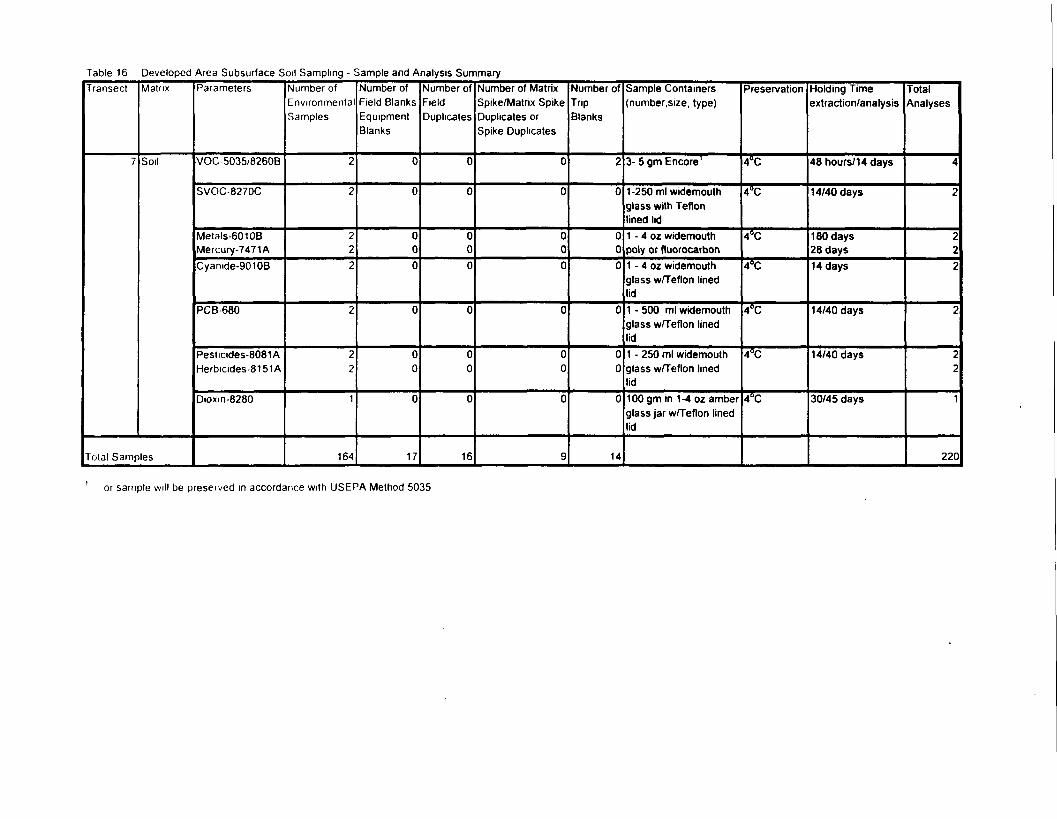
Table 16 Developed Area Subsurface Soil Sampling - Sample and Analysis SummaryTransect
7
Matrix
Soil
Total Samples
Parameters
VOC-5035/8260B
SVOC-8270C
Metals-60106Mercury-7471ACyamde-9010B
PCB680
Pesticides-8081AHerbicides-8151 A
Dioxm-8280
Number ofEnvironmentalSamples
2
2
222
2
22
1
164
Number ofField BlanksEquipmentBlanks
0
0
000
0
00
0
17
Number ofFieldDuplicates
0
0
000
0
00
0
16
Number of MatrixSpike/Matrix SpikeDuplicates orSpike Duplicates
0
0
000
0
00
0
9
Number ofTripBlanks
2
0
000
0
00
0
14
Sample Containers(number.size, type)
3- 5 gm Encore1
1-250 ml widemouthglass with Teflonlined lid1 - 4 oz widemouthpoly or fluorocarbon1 - 4 oz widemouthglass w/Teflon linedlid1 - 500 ml widemouthglass w/Teflon linedlid1 - 250 ml widemouthglass w/Teflon linedlid1 00 gm in 1-4 oz amberglass jar w/Teflon linedlid
Preservation
4°C
4°C
4°C
4°C
4°C
4°C
4°C
Holding Timeextraction/analysis
48 hours/14 days
14/40 days
1 80 days28 days14 days
14/40 days
14/40 days
30/45 days
TotalAnalyses
4
2
222
2
22
1
220
1 or sample will be preserved in accordance with USEPA Method 5035
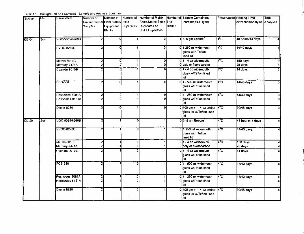
Table 17 Background Soil Samples - Sample and Analysis SummaryStation
EE-04
EE-20
Matrix
Soil
Soil
Parameters
VOC-5035/8260B
SVOC-8270C
Metals-60108Mercury-7471ACyanide-90106
PCB-680
Pesticides-8081AHerbicides-8151A
Dioxm-8280
VOC-5035/8260B
SVOC-8270C
Metals-601 OBMercury-7471ACyanide-901 OB
PCB-680
Pesticides-8081AHerbicides-8151A
Dioxin-8280
Number ofEnvironmentalSamples
2
2
222
2
22
2
2
2
222
2
22
2
Number ofField BlanksEquipmentBlanks
0
0
000
0
00
0
1
1
111
1
11
1
Number ofFieldDuplicates
1
1
111
1
11
1
0
0
000
0
00
0
Number of MatrixSpike/Matrix SpikeDuplicates orSpike Duplicates
0
0
000
0
00
0
1
1
111
1
11
1
Number ofTripBlank-.
1
0
000
0
00
0
0
0
000
0
00
0
Sample Containers(number.size, type)
3- 5 gm Encore1
1 -250 ml widemouthglass with Teflonlined lid1 - 4 oz widemouthpoly or fluorocarbon1 - 4 02 widemouthglass w/Teflon linedlid1 - 500 ml widemouthglass w/Teflon linedlid1 - 250 ml widemouthglass w/Teflon linedlid100 gm in 1-4 oz amberglass jar wfTeflon linedlid3- 5 gm Encore1
1 -250 ml widemouthglass with Teflonlined lid1 - 4 oz widemouthpoly or fluorocarbon1 - 4 oz widemouthglass w/Teflon linedlid1 - 500 ml widemouthglass w/Teflon linedlid1 - 250 ml widemouthglass w/Teflon linedlid100 gm in 1-4 oz amberglass jar w/Teflon linedlid
Preservation
4°C
4°C
4°C
4°C
4°C
4°C
4°C
4°C
4°C
4°C
4°C
4°C
4°C
4°C
Holding Timeextraction/analysis
48 hours/1 4 days
14/40 days
180 days28 days14 days
14/40 days
14/40 days
30/45 days
48 hours/14 days
14/40 days
180 days28 days14 days
14/40 days
14/40 days
30/45 days
TotalAnalyses
4
3
333
3
33
3
4
4
444
4
44
4
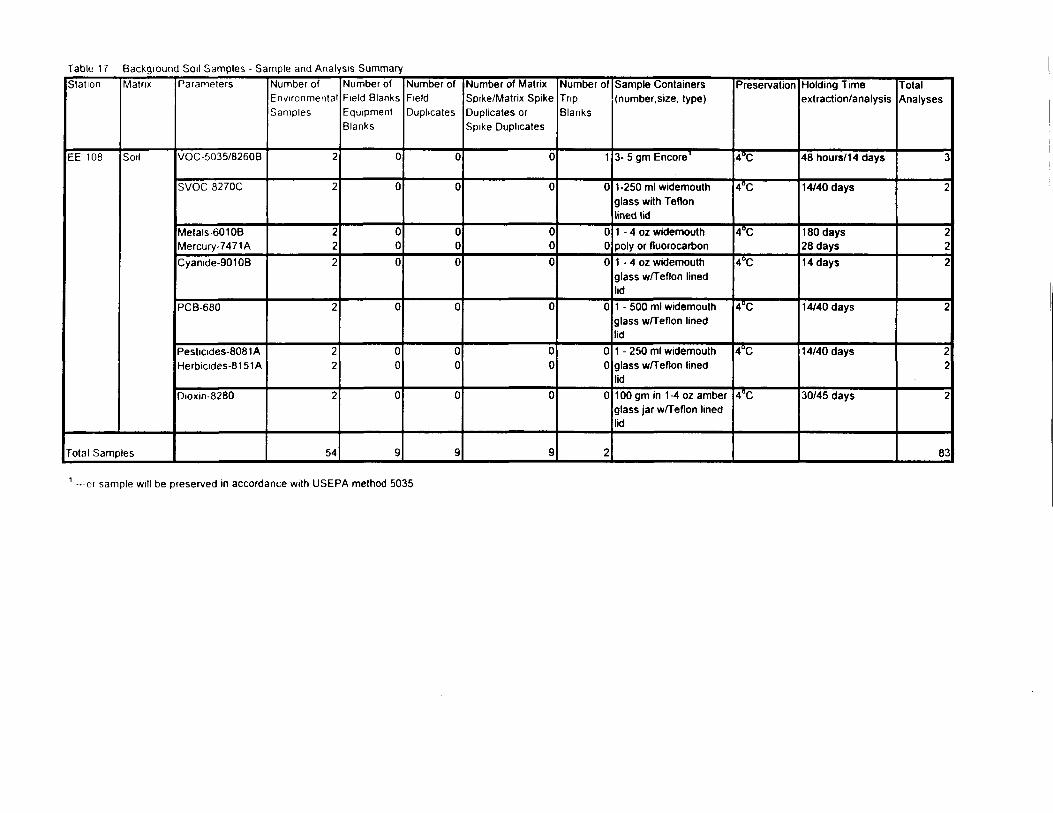
Table 17 Background Soil Samples - Sample and Analysis SummaryStation
EE-108
Matrix
Soil
Total Samples
Parameters
VOC-5035/8260B
SVOC 8270C
Metals 601 OBMercury-7471 ACyanide-90108
PCB-680
Pesticides-8081 AHerbicides-81 51 A
Dioxin-8280
Number ofEnvironmentalSamples
2
2
222
2
22
2
54
Number ofField BlanksEquipmentBlanks
0
0
000
0
00
0
g
Number ofFieldDuplicates
0
0
000
0
00
0
9
Number of MatrixSpike/Matrix SpikeDuplicates orSpike Duplicates
0
0
000
0
00
0
9
Number ofTripBlanks
1
0
000
0
00
0
2
Sample Containers(number.size, type)
3- 5 gm Encore1
1-250 ml widemouthglass with Teflonlined lid1 - 4 oz widemouthpoly or fluorocarbon1 - 4 oz widemouthglass w/Teflon linedlid1 - 500 ml widemouthglass w/Teflon linedlid1 - 250 ml widemouthglass w/Teflon linedlid1 00 gm in 1 -4 oz amberglass jar w/Teflon linedlid
Preservation
4°C
4°C
4°C
4°C
4°C
4°C
4°C
Holding Timeextraction/analysis
48 hours/14 days
14/40 days
180 days28 days1 4 days
14/40 days
14/40 days
30/45 days
TotalAnalyses
3
2
222
2
22
2
83
1 —or sample will be preserved in accordance with USEPA method 5035
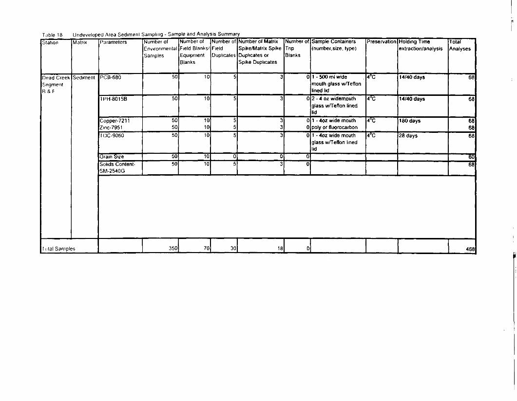
Table 18 Undeveloped Area Sediment Sampling - Sample and Analysis SummaryStation
Dead CreekSegmentB & F
Matrix
Sediment
Total Samples
Parameters
PCB-680
TPH-8015B
Copper-7211Zinc-7951TOC-9060
Grain SizeSolids Content-SM-2540G
Number ofEnvironmentalSamples
50
50
505050
5050
Number ofField Blanks/EquipmentBlanks
10
10
101010
1010
Number ofFieldDuplicates
5
5
555
05
Number of MatrixSpike/Matrix SpikeDuplicates orSpike Duplicates
3
3
333
03
Number ofTripBlanks
0
0
000
00
Sample Containers(number.size, type)
1 - 500 ml widemouth glass wfTeflonlined lid2 - 4 oz widemouthglass w/Teflon linedlid1 - 4oz wide mouthpoly or fluorocarbon1 - 4oz wide mouthglass w/Teflon linedlid
Preservation
4°C
4°C
4°C
4°C
Holding Timeextraction/analysis
14/40 days
14/40 days
180 days
28 days
TotalAnalyses
68
68
686868
6068
350 70 30 18 0 468
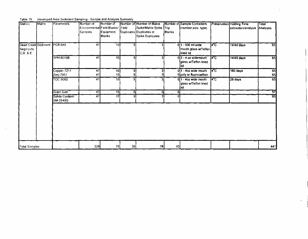
Table 19 Developed Area Sediment Sampling - Sample and Analysis SummaryStation
Dead CreekSegmentsC,D. & E
Matrix
Sediment
Total Samples
Parameters
PCB-680
TPH-8015B
Copper-7211Zinc-7951TOC-9060
Grain SizeSolids Content-SM-2540G
Number ofEnvironmentalSamples
47
47
474747
4747
Number ofField Blanks/EquipmentBlanks
10
10
101010
1010
Number ofFieldDuplicates
5
5
555
05
Number of MatrixSpike/Matrix SpikeDuplicates orSpike Duplicates
3
3
333
03
Number ofTripBlanks
0
0
000
00
Sample Containers(number.size, type)
1 - 500 ml widemouth glass w/Teflonlined lid2 - 4 oz widemouthglass w/Teflon linedlid1 - 4oz wide mouthpoly or fluorocarbon1 - 4oz wide mouthglass w/Teflon linedlid
Preservation
4°C
4°C
4°C
4°C
Holding Timeextraction/analysis
14/40 days
14/40 days
180 days
28 days
TotalAnalyses
65
65
656565
5765
329 70 30 18 10 447
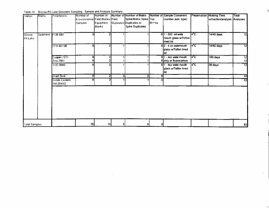
Table 20 Borrow Pit Lake Sediment Sampling - Sample and Analysis SummaryStation
BorrowPit Lake
Matrix
Sediment
Total Samples
Parameters
PCB-680
IPH-8015B
Copper-7211Zinc-7951TOC-9060
Grain SizeSolids Conlent-SM-2540G
Number ofEnvironmentalSamples
8
8
888
88
Number ofField Blanks/EquipmentBlanks
2
2
222
22
Number ofFieldDuplicates
1
1
111
01
Number of MatrixSpike/Matrix SpikeDuplicates orSpike Duplicates
1
1
111
01
Number ofTripBlr^ks
0
0
000
00
Sample Containers(number, size, type)
1 - 500 ml widemouth glass w/Teflonlined lid2 - 4 oz widemouthglass w/Teflon linedlid1 - 4oz wide mouthpoly or fluorocarbon1 - 4oz wide mouthglass w/Teflon linedlid
Preservation
4°C
4°C
4°C
4°C
Holding Timeextraction/analysis
14/40 days
14/40 days
180 days
28 days
TotalAnalyses
12
12
121212
1012
56 14 6 6 0 82
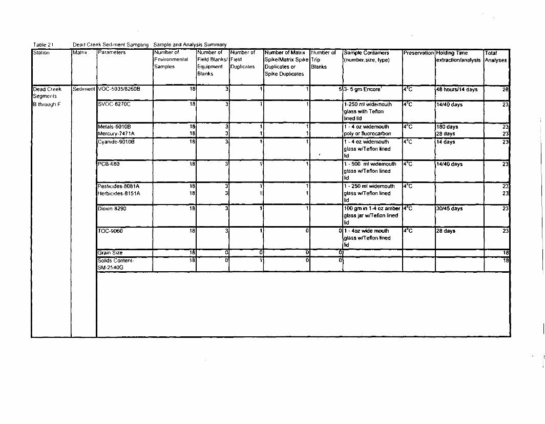
Table 21 Dead Creek Sediment Sampling - Sample and Analysis SummaryStation
Dead CreekSegmentsB through F
Matrix
Sediment
Parameters
VOC 5035/8260B
SVOC 8270C
Metals-6010BMercury- 7471 ACyanide-90108
PCB-680
Pesticides-8081AHerbicides-8151A
Dioxin 8290
TOC-9060
Grain SizeSolids Contenl-SM-2MOG
Number ofEnvironmentalSamples
18
18
181818
18
1818
18
18
1818
Number ofField Blanks/EquipmentBlanks
3
3
333
3
33
3
3
00
Number ofFieldDuplicates
1
1
111
1
11
1
1
01
Number of MatrixSpike/Matrix SpikeDuplicates orSpike Duplicates
1
1
111
1
11
1
0
00
Number ofTripBlanks
5
1
0
00
Sample Containers(number.size, type)
3- 5 gm Encore1
1-250 ml widemouthglass with Teflonlined lid1 - 4 oz widemouthpoly or fluorocarbon1 - 4 oz widemouthglass w/Teflon linedlid1 - 500 ml widemouthglass w/Teflon linedlid1 - 250 ml widemouthglass w/Teflon linedlid100 gm in 1-4 oz amberglass jar w/Teflon linedlid1 - 4oz wide mouthglass w/Teflon linedlid
Preservation
4°C
4°C
4°C
4°C
4°C
4°C
4°C
4°C
Holding Timeextraction/analysis
48 hours/14 days
14/40 days
180 days28 days14 days
14/40 days
30/45 days
28 days
TotalAnalyses
28
23
232323
23
2323
23
23
1818
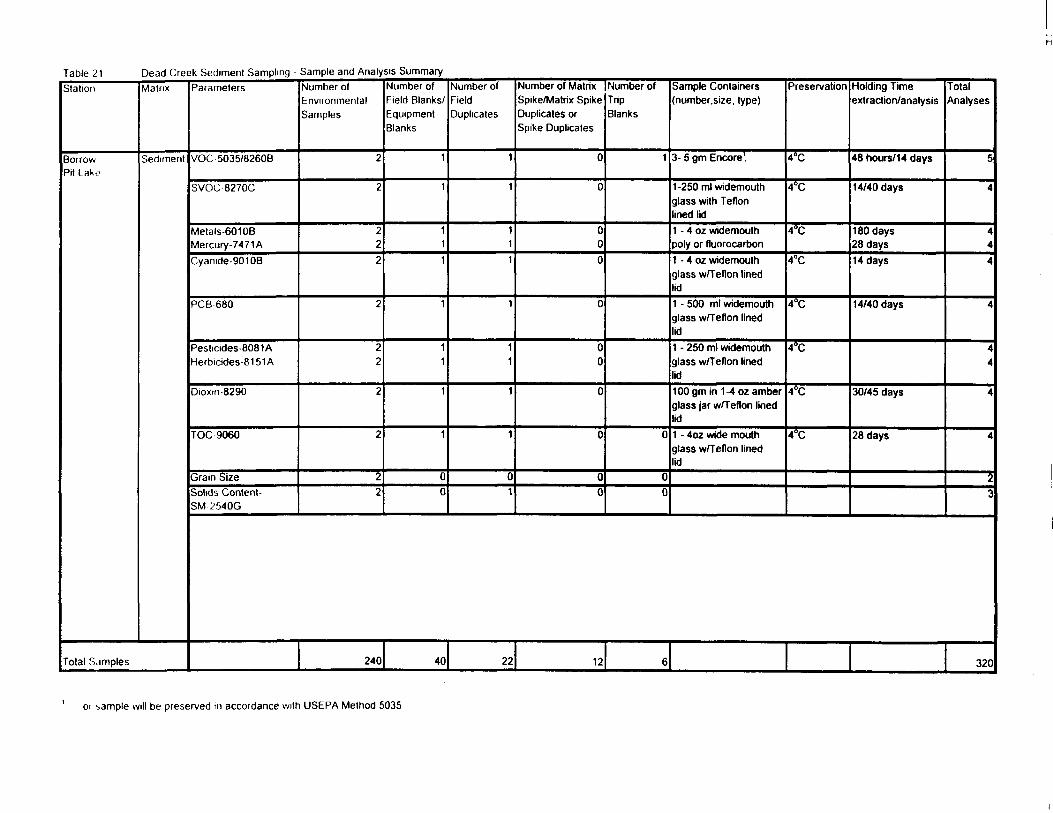
Table 21 Dead Creek Sediment Sampling - Sample and Analysis SummaryStation
BorrowPit Lake
Matrix
Sediment
Total Samples
Parameters
VOC 5035/8260B
SVOC8270C
Metals-60108Mercury-74 71 ACyanide-90108
PCB 680
Pesticides-8081 AHerbicides-81 51 A
Dioxm 8290
TOC9060
Grain SizeSolids Content-SM 2540G
Number ofEnvironmentalSamples
2
2
222
2
22
2
2
22
Number ofField Blanks/EquipmentBlanks
1
1
111
1
11
1
1
00
Number ofFieldDuplicates
1
1
111
1
11
1
1
01
Number of MatrixSpike/Matrix SpikeDuplicates orSpike Duplicates
0
0
000
0
00
0
0
00
Number ofTripBlanks
1
0
00
Sample Containers(number.size, type)
3- 5 gm Encore!
1-250 ml widemouthglass with Teflonlined lid1 - 4 oz widemouthpoly or fluorocarbon1 - 4 oz widemouthglass w/Teflon linedlid1 - 500 ml widemouthglass w/Teflon linedlid1 - 250 ml widemouthglass w/Teflon linedlid100 gm in 1-4 oz amberglass jar w/Teflon linedlid1 - 4oz wide mouthglass w/Teflon linedlid
Preservation
4°C
4°C
4°C
4°C
4°C
4°C
4°C
4°C
240 40 22 12 6
Holding Timeextraction/analysis
48 hours/14 days
14/40 days
180 days28 days14 days
14/40 days
30/45 days
28 days
TotalAnalyses
5
4
444
4
44
4
4
23
320
01 bample will be preserved in accordance with USEPA Method 5035
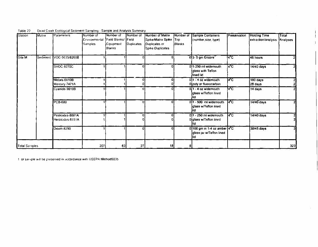
Table 22 Dead Creek Ecological Sediment Sampling - Sample and Analysis SummaryStation
SiteM
Matrix
Sediment
Total Samples
Parameters
VOC-5035/8260B
SVOC-8270C
Metals-60108Mercury-7471ACyanide-90108
PCB-680
Pesticides-8081AHerbicides-81 51A
Dioxin-8290
Number ofEnvironmentalSamples
1
1
111
1
11
1
207
Number ofField Blanks/EquipmentBlanks
1
1
111
1
11
1
63
Number ofFieldDuplicates
0
0
000
0
00
0
27
Number of MatrixSpike/Matrix SpikeDuplicates orSpike Duplicates
0
0
000
0
00
0
18
Number ofTripBlanks
0
0
000
0
00
0
8
Sample Containers(number, size, type)
3- 5 gm Encore1
1-250 ml widemouthglass with Teflonlined lid1 - 4 oz widemouthpoly or fluorocarbon1 - 4 oz widemouthglass w/Teflon linedlid1 - 500 ml widemouthglass w/Teflon linedlid1 - 250 ml widemouthglass w/Teflon linedlid100 gm in 1-4 oz amberglass jar w/Teflon linedlid
Preservation
4°C
4°C
4°C
4°C
4°C
4°C
4°C
Holding Timeextraction/analysis
48 hours
14/40 days
180 days28 days14 days
14/40 days
14/40 days
30/45 days
TotalAnalyses
2
2
222
2
22
2
323
1 or sample will be preserved in accordance with USEPA Method5035
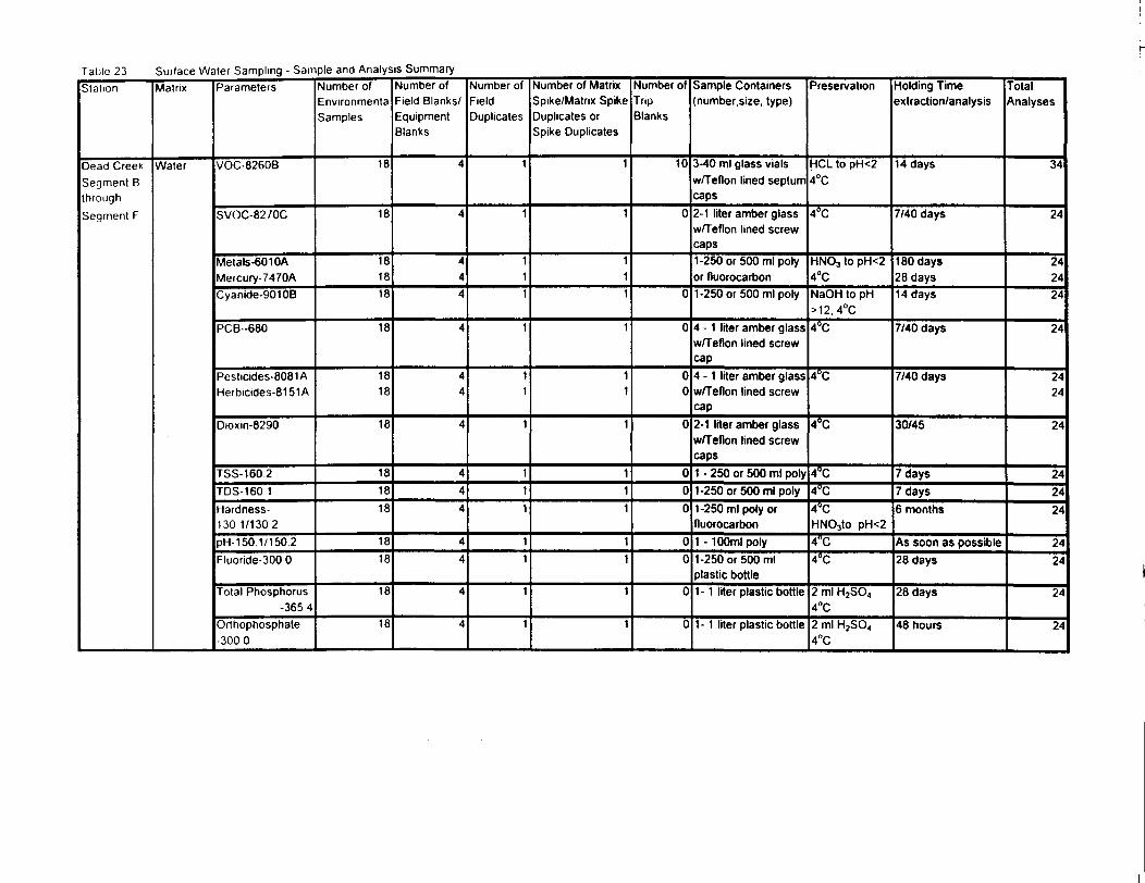
Table 23 Surface Watei Sampling - Sample and Analysis SummaryStation
Dead CreekSegment BthroughSegment F
Matrix
Water
Parameters
VOC-8260B
SVOC-8270C
Metals-60 10AMercury-7470ACyanide-90108
PCB--680
Pesticides-8081 AHerbicides-81 51 A
Dioxin-8290
TSS-1602TDS-160 1Hardness-130 1/1302pH 150.1/1502Fluoride-300 0
Total Phosphorus-3654
Orthophosphate-3000
Number ofEnvironmentSamples
18
18
181818
18
1818
18
181818
1818
18
18
Number ofField Blanks/EquipmentBlanks
4
4
444
4
44
4
444
44
4
4
Number ofFieldDuplicates
1
1
111
1
11
1
111
11
1
1
Number of MatrixSpike/Matrix SpikeDuplicates orSpike Duplicates
1
111
1
11
1
111
11
1
1
Number ofTripBlanks
10
0
0
0
00
0
000
00
0
0
Sample Containers(number, size, type)
3-40 ml glass vialsw/Teflon lined septumcaps2-1 liter amber glassw/Teflon lined screwcaps1-250 or 500 ml polyor fluorocarbon1-250 or 500 ml poly
4 - 1 liter amber glassw/Teflon lined screwcap4-1 liter amber glassw/Teflon lined screwcap2-1 liter amber glassw/Teflon lined screwcaps1 - 250 or 500 ml poly1-250 or 500 ml poly1-250 ml poly orfluorocarbon1 - 100ml poly1-250 or 500 mlplastic bottle1- 1 liter plastic bottle
1- 1 liter plastic bottle
Preservation
HCL to pH<24°C
4°C
HNO3 to pH<24°CNaOH to pH>12, 4°C4°C
4°C
4°C
4°C4°C4°CHNO3to pH<24°C4°C
2 ml H2SO4
4°C2 ml H2SO«4°C
Holding Timeextraction/analysis
14 days
7/40 days
180 days28 days14 days
7/40 days
7/40 days
30/45
7 days7 days6 months
As soon as possible28 days
28 days
48 hours
TotalAnalyses
34
24
242424
24
2424
24
242424
2424
24
24
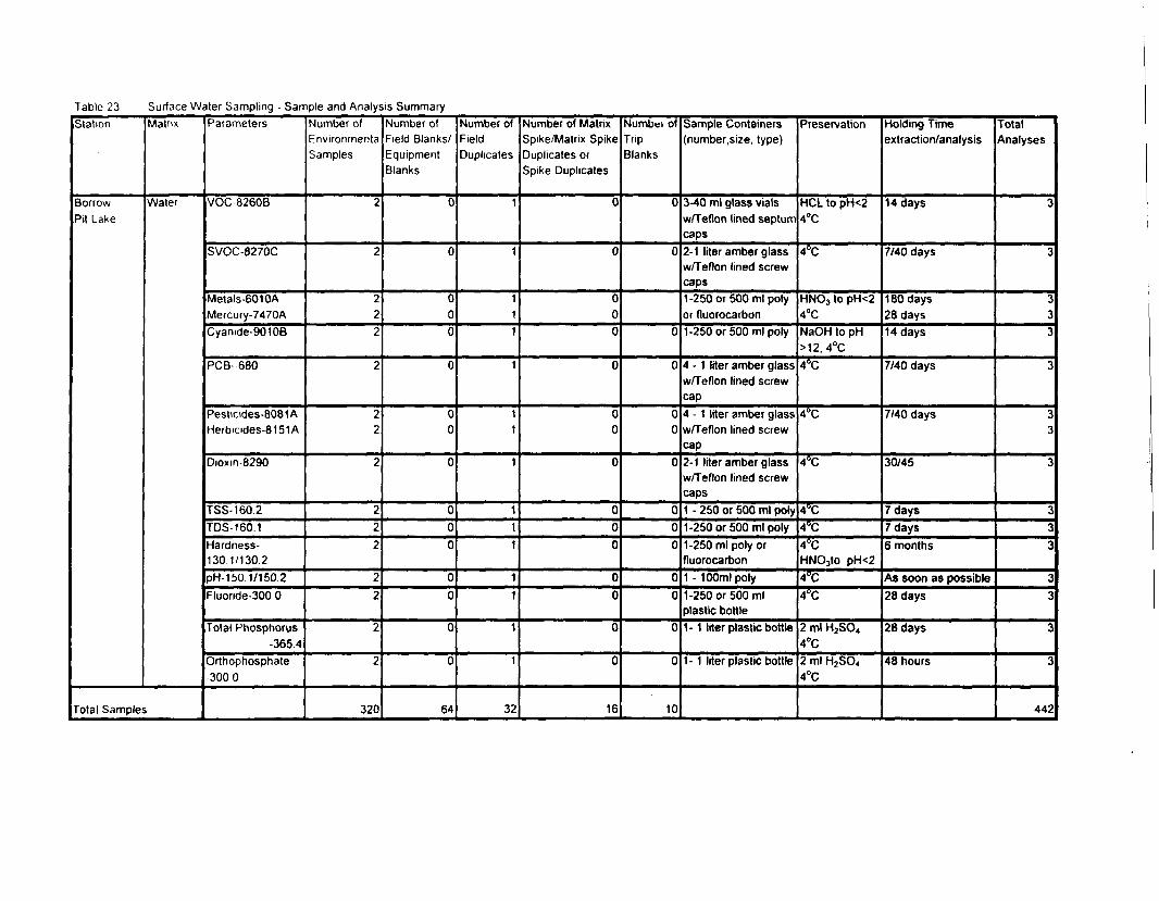
Table 23 Surface Water Sampling - Sample and Analysis SummaryStation
BorrowPit Lake
Matrix
Water
Total Samples
Parameters
VOC 8260B
SVOC-8270C
Metals-6010AMercury-7470ACyanide-90108
PCB-680
Pesticides-8081AHerbicides-8151A
Dioxm-8290
TSS-160.2TDS-1601Hardness-130 1/130.2pH-150.1/1502Fluonde-300 0
Total Phosphorus-365.4
Orthophosphate-3000
Number ofEnvironmentaSamples
2
2
222
2
22
2
222
22
2
2
320
Number ofField Blanks/EquipmentBlanks
0
0
000
0
00
0
000
00
0
0
64
Number ofFieldDuplicates
1
1
111
1
11
1
111
11
1
1
32
Number of MatrixSpike/Matrix SpikeDuplicates orSpike Duplicates
0
0
000
0
00
0
000
00
0
0
16
Numbei ofTripBlanks
0
0
0
0
00
0
000
00
0
0
10
Sample Containers(number.size, type)
3-40 ml glass vialsw/Teflon lined septumcaps2-1 liter amber glassw/Teflon lined screwcaps1-250 or 500 ml polyor fluorocarbon1-250 or 500 ml poly
4 - 1 liter amber glassw/Teflon lined screwcap4 - 1 liter amber glassw/Teflon lined screwcap2-1 liter amber glassw/Teflon lined screwcaps1 - 250 or 500 ml poly1-250 or 500 ml poly1-250 ml poly orfluorocarbon1- 100ml poly1-250 or 500 mlplastic bottle1- 1 liter plastic bottle
1- 1 liter plastic bottle
Preservation
HCL to pH<24°C
4°C
HNO3 to pH<24°CNaOH to pH>12, 4°C4°C
4°C
4°C
4°C4°C4°CHNOjto pH<24°C4°C
2 ml H2SO4
4°C2 ml H2SO«4°C
Holding Timeextraction/analysis
14 days
7/40 days
180 days28 days14 days
7/40 days
7/40 days
30/45
7 days7 days6 months
As soon as possible28 days
28 days
48 hours
TotalAnalyses
3
3
333
3
33
3
333
33
3
3
442
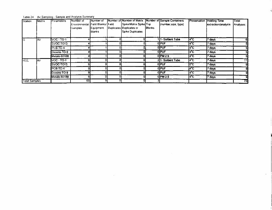
Table 24 Air Sampling - Sample and Analysis SummaryStation
G
H,I,L
Matrix
Air
Air
Total Samples
Parameters
VOC - TO-1SVOC-TO13PCB-TO-4Dioxins-TO-9Metals-60108VOC - TO-1SVOC-T013PCB-TO-4Dioxins-TO-9Metals-60108
Number ofEnvironmentalSamples
4444499999
65
Number ofField Blanks/EquipmentBlanks
11111000005
Number ofFieldDuplicates
00000000000
Number of MatrixSpike/Matrix SpikeDuplicates orSpike Duplicates
00000000000
Number ofTripBlanks
10000200003
Sample Containers(number, size, type)
1-SorbentTubePUFPUFPUFPM2.51- Sorbent TubePUFPUFPUFPM2.5
Preservation
4°C4°C4°C4°C4°C4°C0°C4°C4°C4°C
Holding Timeextraction/analysis
7 days7 days7 days7 days7 days7 days7 days7 days7 days7 days
TotalAnalyses
65555
119999
73

FKitlRES
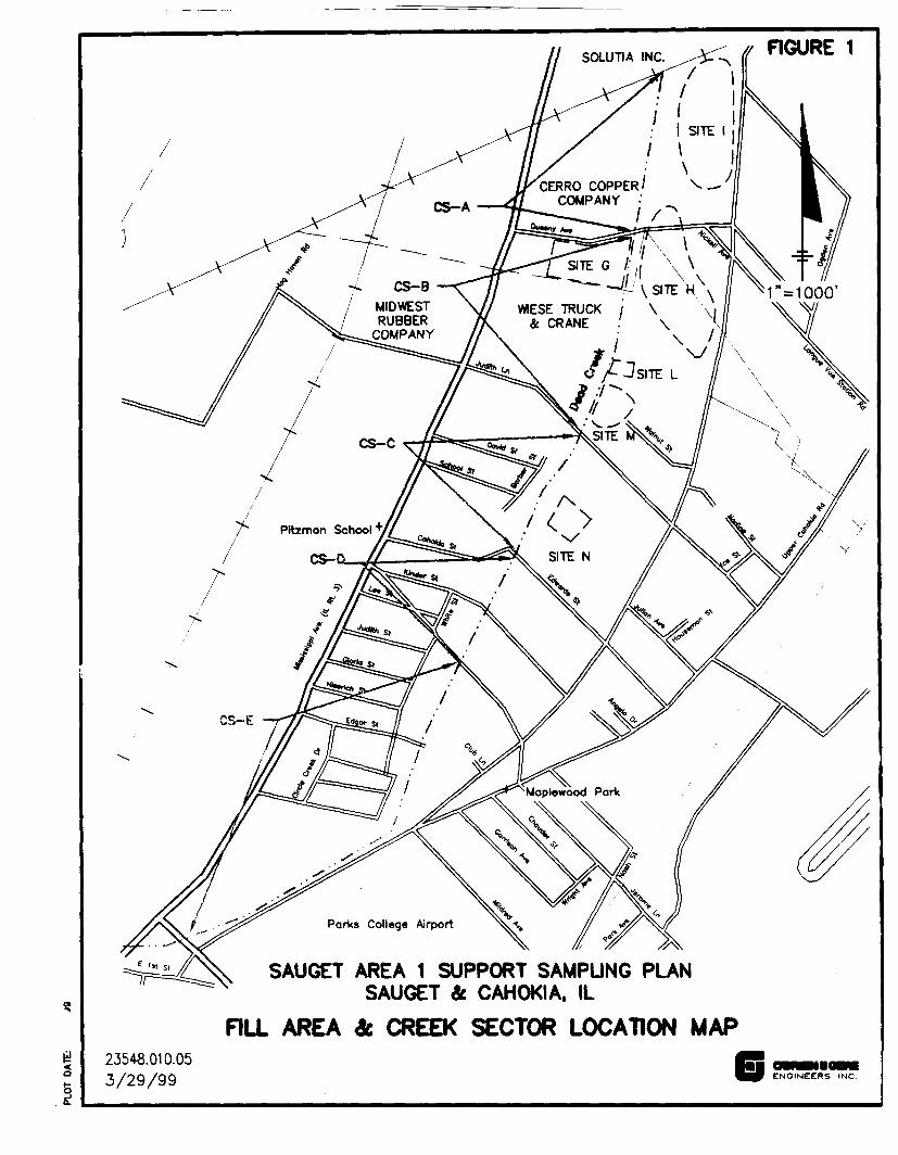
FIGURE 1
MIDWESTRUBBER
COMPANY
WIESE TRUCK / \ \,' CRANE . \ '
SAUGET AREA 1 SUPPORT SAMPUNG PLANSAUGET & CAHOKIA, IL
RLL AREA SECTOR LOCATION MAP23548.010.053/29/99 |̂p ENGINEERS INC.
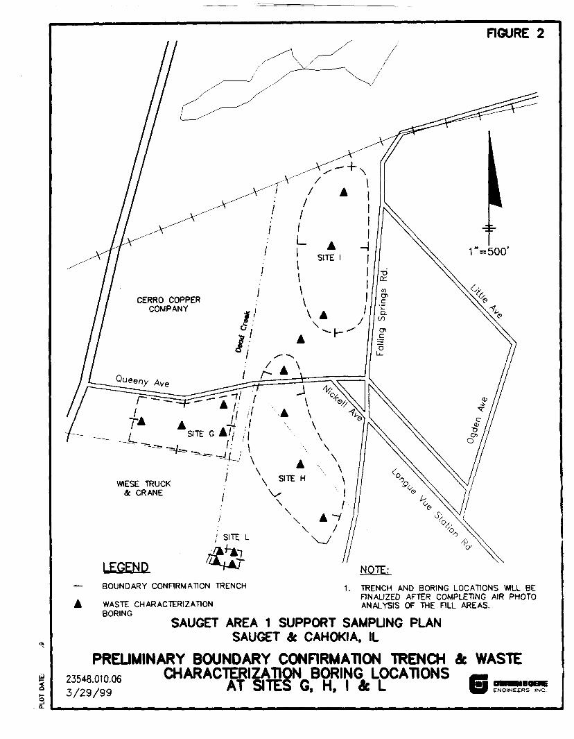
FIGURE 2
CERRO COPPERCOMPANY
VSITE G A? ''
WIESE TRUCK& CRANE
LEGENDBOUNDARY CONFIRMATION TRENCH
NOTE:
1. TRENCH AND BORING LOCATIONS WILL BEFINALIZED AFTER COMPLETING AIR PHOTOANALYSIS OF THE FILL AREAS.A WASTE CHARACTERIZATION
BORINGSAUGET AREA 1 SUPPORT SAMPUNG PLAN
SAUGET & CAHOKIA, IL
PREUMINARY BOUNDARY CONFIRMATION TRENCH & WASTE2354801006 CHARACTERIZATION. BORING LOCATIONS3/29/99 *' SIAT SITES G, H, I & L ENGINEERS INC.
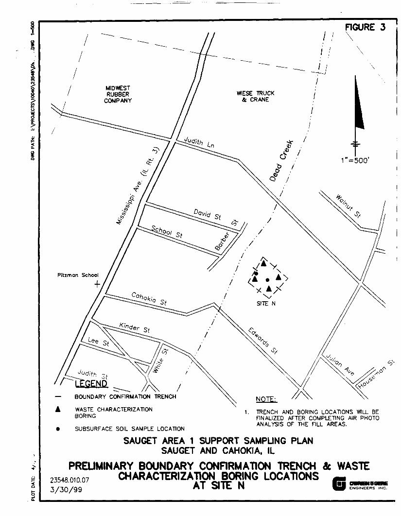
FIGURE 3
1
I
<a
3a.
MIDWESTRUBBER
COMPANYWIESE TRUCK
& CRANE
Pitzman School
WASTE CHARACTERIZATIONBORING
1. TRENCH AND BORING LOCATIONS WILL BEFINALIZED AFTER COMPLETING AIR PHOTOANALYSIS OF THE FILL AREAS.
• SUBSURFACE SOIL SAMPLE LOCATION
SAUGET AREA 1 SUPPORT SAMPLING PLANSAUGET AND CAHOKIA, IL
PREUMINARY BOUNDARY CONRRMATION TRENCH it WASTE2354301007 CHARACTERIZATION BORING LOCATIONS3/30/99 AT SITE N G ENGINEERS INC.
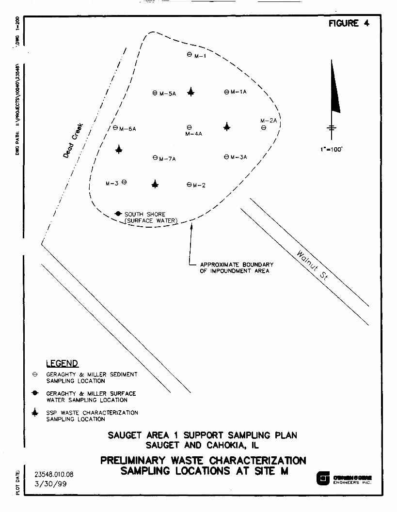
FIGURE 4
M-1
XX\
8M-5A 9M-1A \\\
i /eM-6A eM-4A
0M-7A
M-3 ©
M-2A± e
0M-3A //
//
\
&M-2
\>- SOUTH SHORE^(SURFACE WATER).
<— APPROXIMATE BOUNDARYOF IMPOUNDMENT AREA
GERAGHTY & MILLER SEDIMENTSAMPLING LOCATION
GERAGHTY tc. MILLER SURFACEWATER SAMPLING LOCATION
SSP WASTE CHARACTERIZATIONSAMPLING LOCATION
r=ioo'
23548.010.083/30/99
SAUGET AREA 1 SUPPORT SAMPUNG PLANSAUGET AND CAHOKIA, IL
PREUMINARY WASTE CHARACTERIZATIONSAMPUNG LOCATIONS AT SITE M
ENGINEERS INC.
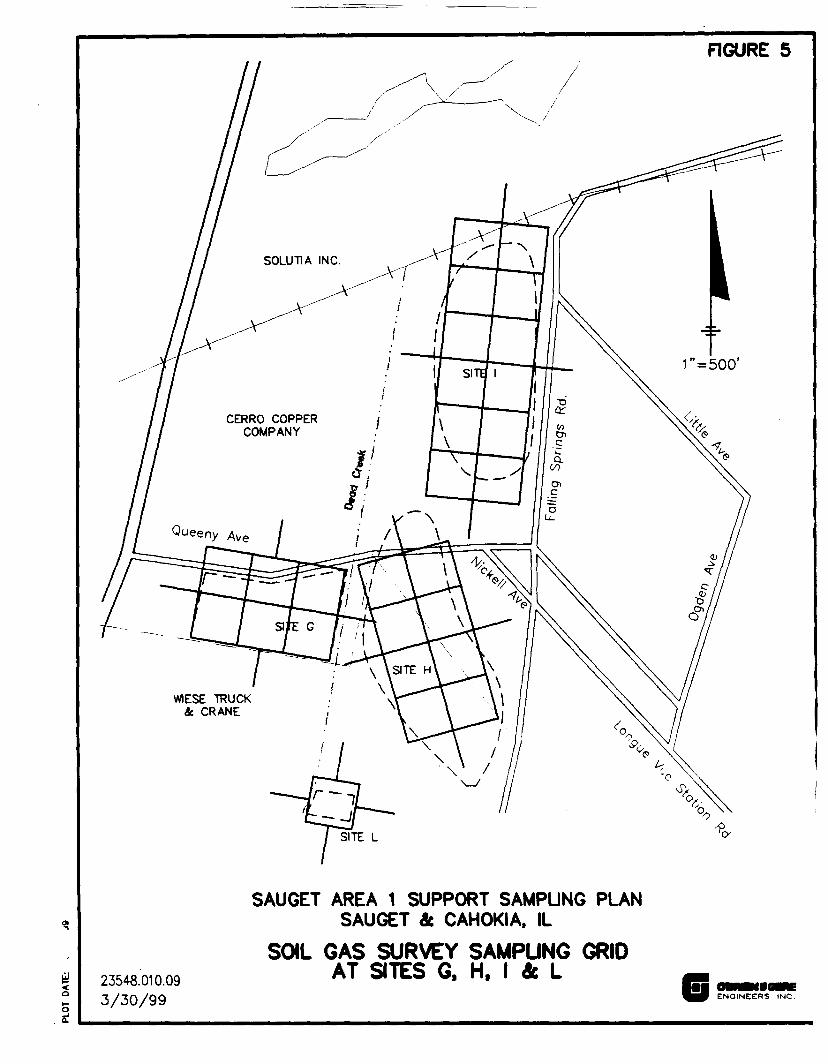
FIGURE 5
CERRO COPPERCOMPANY
£aI
23548.010.093/30/99
SAUGET AREA 1 SUPPORT SAMPUNG PLANSAUGET & CAHOKIA, IL
SOIL GAS SURVEY SAMPUNG GRIDAT SITES G, H, I & L
ENGINEERS INC.
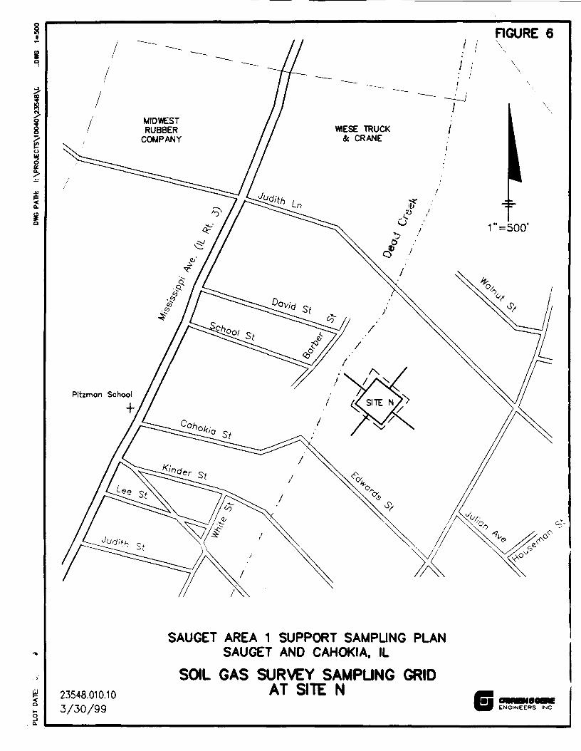
RGURE 6
MIDWESTRUBBER
COMPANYWIESE TRUCK
it CRANE
23548.010.103/30/99
SAUGET AREA 1 SUPPORT SAMPUNG PLANSAUGET AND CAM OK I A, IL
SOIL GAS SURVEY SAMPUNG GRIDAT SITE N
ENGINEERS INC
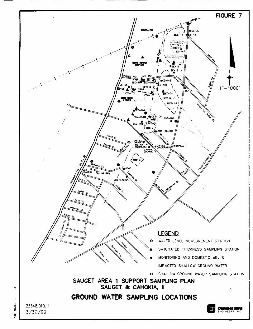
FIGURE 7
WATER LEVEL MEASUREMENT STATION
SATURATED THICKNESS SAMPLING STATION
MONITORING AND DOMESTIC WELLS
IMPACTED SHALLOW GROUND WATER
O SHALLOW GROUND WATER SAMPLING STATION
SAUGET AREA 1 SUPPORT SAMPUNG PLANSAUGET & CAHOKIA. IL
GROUND WATER SAMPUNG LOCATIONS2354S.010.113/30/99
_ ^^ENGINEERS INC.
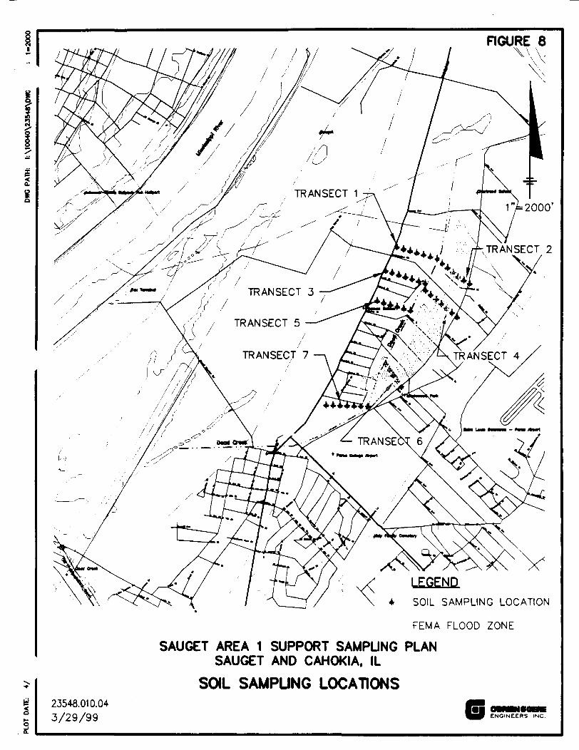
FIGURE 8V\\-
2000'
TRANSECT 5
TRANSECT
LEGEND.SOIL SAMPLING LOCATION
FEMA FLOOD ZONE
SAUGET AREA 1 SUPPORT SAMPUNG PLANSAUGET AND CAHOKIA, IL
SOIL SAMPUNG LOCATIONS23548.010.043/29/99 G ENGINEERS INC.
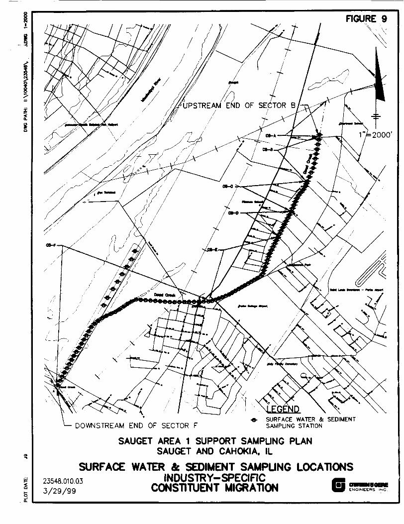
FIGURE 9V, \,
2000'
UPSTREAM END OF SECTOR B
DOWNSTREAM END OF SECTOR FSURFACE WATER & SEDIMENTSAMPUNG STATION
SAUGET AREA 1 SUPPORT SAMPUNG PLANSAUGET AND CAHOKIA, IL
SURFACE WATER & SEDIMENT SAMPUNG LOCATIONS2354801003 INDUSTRY-SPECIFIC3/29/99 CONSTITUENT MIGRATION ENGINEERS INC.
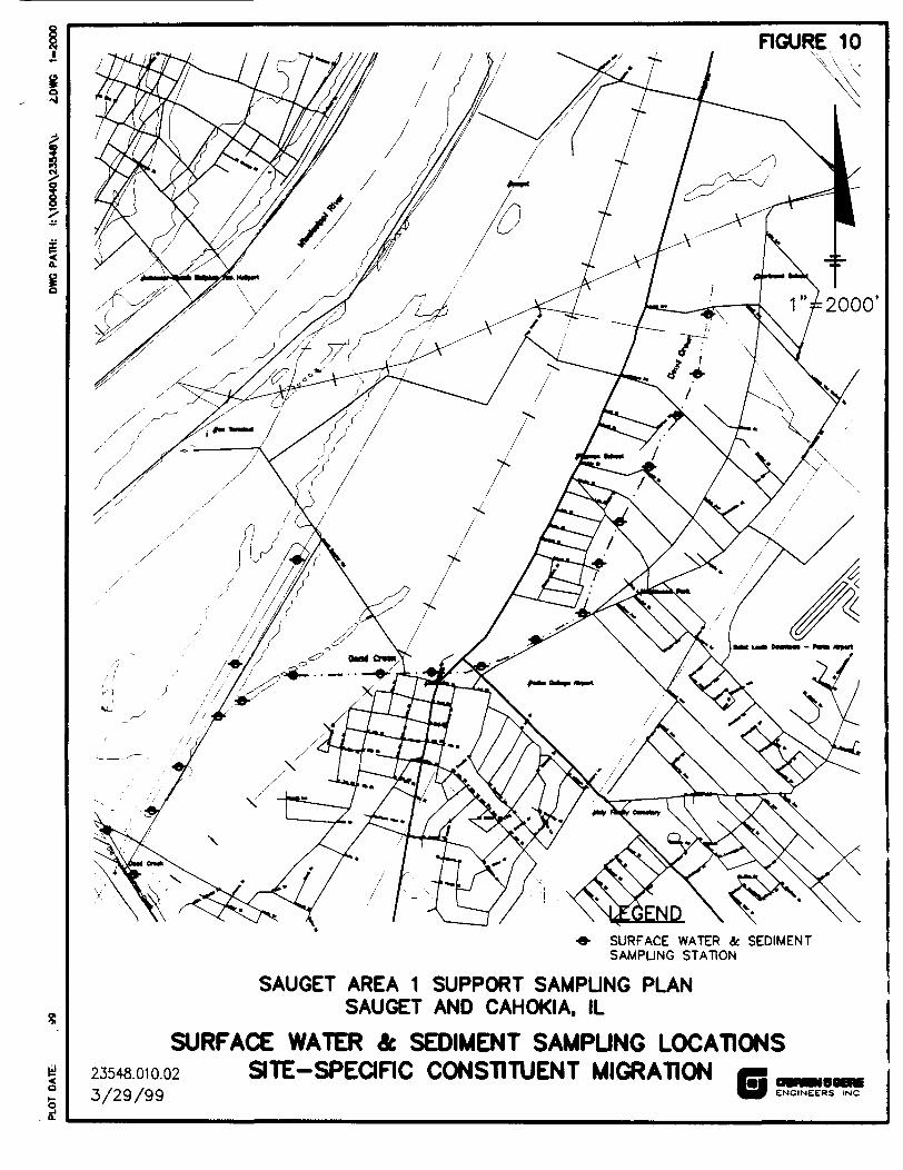
FIGURE 10
2000'
•e- SURFACE WATER ic SEDIMENTSAMPUNG STATION
SAUGET AREA 1 SUPPORT SAMPUNG PLANSAUGET AND CAHOKIA, IL
SURFACE WATER & SEDIMENT SAMPUNG LOCATIONS2354801002 SITE-SPECIFIC CONSTITUENT MIGRATION3/29/99 ENGINEERS INC.
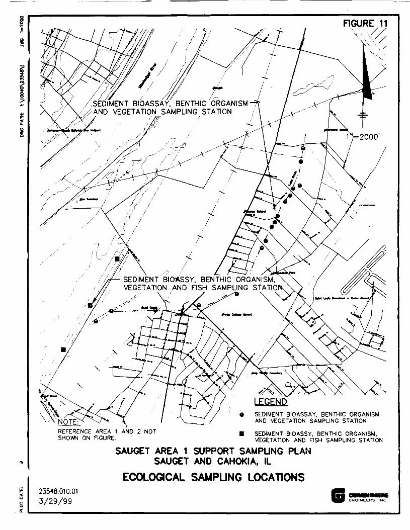
FIGURE 11
SEDIMENT BIOASSAY. BENTHIC ORGANISMVEGETATION SAMPLING STATION /
SEDIMENT BIO*SSY, BENTHIC ORGANISM,VEGETATION AND FISH SAMPLING STATIC
REFERENCE AREA 1 AND 2 NOTSHOWN ON FIGURE.
SEDIMENT BIOASSAY, BENTHIC ORGANISMAND VEGETATION SAMPLING STATION
SEDIMENT BIOASSY, BENTHIC ORGANISM.VEGETATION AND FISH SAMPLING STATION
SAUGET AREA 1 SUPPORT SAMPUNG PLANSAUGET AND CAHOKIA, II
ECOLOGICAL SAMPUNG LOCATIONS23548.010.013/29/99 ENGINEERS INC.