u.s. department of the interior u.s. geological - usgs
TRANSCRIPT

U.S. DEPARTMENT OF THE INTERIOR U.S. GEOLOGICAL SURVEY
DESCRIPTION OF A HYDRAULIC SEDIMENT SQUEEZER
by
Frank T. Manheim, Eric G. Brooks, and William J. Winters
Open-File Report 94-584
This report is preliminary and has not been reviewed for conformity with U. S. Geological Survey editorial standards and stratigraphic nomenclature. Any use of trade names or suppliers company names is for descriptive purposes only and does not imply endorsement by the USGS.
Woods Hole, Massachusetts 02543
September 1994

TABLE OF CONTENTS
Abstract 1
Introduction 1
Description of The Hydraulic Squeezer 3
Assembly & Operating Procedures 5
Limitations & Safety Concerns 11
Alternate Devices For Extracting Pore Fluid From Sediment 12
Acknowledgments 13
References 14
Appendix A: Field Sampling Concerns 31
Appendix B: Interstitial Water Study 34
Appendix C: Determining Initial Water Content FromSqueezed Sediment Specimens 39

ABSTRACT
A hydraulic sediment squeezer has been constructed and has successfully been used to extract pore water from sediments of variable consolidation. This report will provide the following information related to the apparatus: (1) description of the mechanical components, (2) operational procedures, (3) safety concerns, and (4) discussion of proper field methods and equipment to insure accurate measurement of the sampled fluid's constituents. A case study is presented in an appendix.
INTRODUCTION
A major breakthrough in extraction of interstitial fluids was achieved in the post-World War II period by the late Russian geochemist, P. A. Kriukov (Kriukov, 1947). Using a self-sealing, free rubber gasket principle with steel squeezers and hydraulic presses, Kriukov was able to extract fluids from even the most consolidated sedimentary rocks such as drill cores at pressures up to 980 MN/m^. For a detailed historical review of methodologies for interstitial water extraction see Kriukov and Manheim (1982).
Modified squeezers based on the free gasket were developed for the U. S. National Science Foundation's Joint Oceanographic Institutions Deep Earth Sampling Project

(JOIDES) and Deep Sea Drilling Projects (DSDP) in the 1960's by F. T. Manheim (Manheim and Gieskes, 1984), and continued to be utilized routinely in successor programs, the International Program for Ocean Drilling (IPOD), and Ocean Drilling Program (ODP). Kohout and others (1977) also elegantly demonstrated that saline waters analyzed after core squeezing closely modeled electrical conductivity in a borehole on Nantucket Island (Fig. 1). The squeezing technique was used in continental shelf drilling by the U. S. Geological Survey on the Atlantic Margin (Hathaway and others, 1979; Kohout and others, 1988). The technique is increasingly being used to extract fluid for analysis of ground water problems (e.g., Pucci and others, 1992). Lower-pressure, simple modifications of these squeezers are discussed later.
The purpose of this paper is to review the construction and operation of the hydraulic sediment squeezer, provide descriptive construction details not given in previous documentation, and give an example of experimental use for unconsolidated sediments in a coastal environment. This kind of deployment is believed to have potential applications to geotechnical studies.

DESCRIPTION OF THE HYDRAULIC SQUEEZER
The squeezer system consists of three major components: (1) a hydraulic press, (2) a capsule that transmits pressure from the press to the sediment, and (3) a syringe for collecting the resultant pore fluid. The sediment capsules were constructed from revised design plans of a prototype (Manheim, 1966). To achieve maximum efficiency, corrosion resistance and maintain optimum structural rigidity (under pressure) all capsule parts are commonly made of 316 stainless steel giving the squeezer a mass of approximately 71 kg. However, harden stainless steel can also be used.
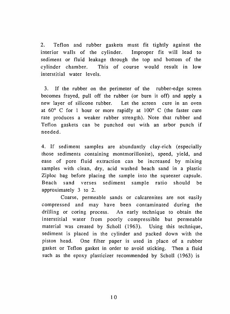
The hydraulic apparatus consists of a hydraulic bottle jack, a mechanical pumping handle with two ranges of mechanical motion (full and half increments), a pressure gauge, a pressure release valve, and three (triangularly configured) vertical screw columns, which are all set in a steel base pedestal (Figs. 2-5). The squeezer press utilizes a hydraulic piston to provide the necessary pressure to initiate pore water discharge. A thick steel base plate is attached to the hydraulic piston. Positioned above the base plate is another plate of similar thickness. This top plate is attached to a chain drive, which in turn is attached to a crank system (which raises and lowers the top plate). Both the top plate and the lower plate are guided up and down along the three screw columns.
A total of 4 different size squeezer capsules were made. The largest squeezer capsule can hold about 50 cc of sample sediment, while the smallest squeezer capsule can hold approximately 15 - 20 cc of sediment.

The largest two squeezer capsules use a 9 cm diameter filter paper circle, and can yield a few milliliters to more than 15 milliliters of fluid, depending on initial sediment water content and permeability. Because it imparts a lower compressional stress to the sediment, the largest squeezer is typically used on soft fine-grained sediment with high water content. The small squeezer capsules are used on stiff fine-grained or coarse grained sediment with low water content. The two smaller squeezer capsules use 4.25 cm diameter filter circles and can yield from 1 to 5 ml of fluid. Figures 6-8 show representative views of a disassembled and assembled capsule and dimensions for the smallest capsule. Table 1 lists and describes the various capsule components and accessories needed to use the squeezer.
Use of the squeezer requires that a capsule (which contains the sediment sample) be placed between the base and top hydraulic press plates (Figs 9 and 10). When hydraulic pressure is increased, it causes self-sealing rubber gaskets to expand against the walls of the stainless steel cylinder. As the sediment is compressed pore fluid is forced through filter paper disks into a conduit tube which leads to a disposable syringe (inserted into the base unit of the squeezer capsule). The conduit tube at the base of the steel capsule is reamed out to permit easy fitting of the standard "Luer" taper of a syringe nose. Interstitial fluid can be further filtered by a "Swinney" filter attached to the syringe (Lockey, 1962). Total time from set up to clean up should take approximately 15-30 minutes for a single sample.

ASSEMBLY AND OPERATING PROCEDURES
A. Hydraulic Press
A-l. Check fluid level in press and add fluid if required.
A-2. By turning the crank, position the top plate at approximately the correct height for the squeezer being used.
B. Squeezer Capsule Assembly
The squeezer capsules consist of four basic stainless steel parts. A base (which contains a conduit tube for pore water flow into a syringe), a base plug, a cylinder chamber, and a piston head (See Fig. 8).
B-l. Procedural steps B-l to B-3 should be completed while the sediment is still in its storage container to minimize sample evaporation. Assemble base (containing syringe hole), rubber- doughnut ring, and stainless steel base plug to form base unit.
B-2. Attach base unit to cylinder unit. Pay close attention to the correct orientation of the cylinder unit. The cylinder unit is marked on the top and bottom. Improper orientation of the cylinder unit could cause scoring, jamming of the piston head, and possible leakage during an experiment.
B-3. Once the base unit and the cylinder unit are combined, insert the rubber-edged screen and 2-3 filter papers

(See Table 1). Note: If a rubber-edged screen must be constructed, cut a stainless steel mesh screen to fit within the cylinder. Then place a thin layer of silicon rubber on both sides of the screen or use thin (1.6-mm) rubber gaskets, one on each side of the screen.
B-4. Working quickly, trim off any external layers from the core section (to avoid contamination), and place 10-15 cc of sediment for the small squeezer and 20-50 cc of sediment for the large squeezer inside the cylinder. For precise measurement of the sediment volume during sampling, we recommend using a 50 cc syringe with the nose cut off. This allows for quick and easy recovery of the sediment sample with a minimal degree of hand contact. Make sure the sample is perfectly centered within the cylinder to avoid uneven squeezing of the sediment which would lead to an irregularly shaped pellet.
B-5. Immediately insert two pieces of filter paper, a Teflon gasket, followed by a rubber gasket and the piston head. Press the piston head down by hand and place the entire capsule along with a steel spacer block (to accommodate the syringe) in the center of the hydraulic press. Use only aluminum or steel spacer blocks (wooden spacer blocks tend to splinter under experimental pressure loads). Lower the upper steel press plate of the apparatus until marginal contact with the piston head is made. Then, using the full range of mechanical motion with one or two pumps from the hydraulic handle, lock the squeezer capsule in place, and insert a syringe into the base pedestal (with plunger fully depressed) (See Figs. 9 and 10).

C. Squeezer Operation
Plastic gloves should be worn through the entire procedure to avoid contamination of pore water. Note: The plunger on the disposable syringe may be pushed outward by gases expelled from the squeezer. When applying pressure for the first time remove the syringe, depress the syringe-plunger, and re-insert the syringe even if a few drops of liquid have been collected already.
C-l. Apply pressure gently at first to avoid formation of a impermeable sediment layer (at the juncture between the filter paper and the sediment). Gradually increase pressure as required to collect fluid in the syringe. The full range of motion of the mechanical handle (handle fully inserted) should be used only to bring the press plates into contact with the squeezer capsule. Once this is achieved, pressure can then be gently raised by pulling the handle half way out (which cuts the range of motion in half). Sandy materials can be squeezed rapidly, whereas clays need to be squeezed more slowly.
C-2. When the syringe is full or has as much pore fluid as is needed, withdraw the plunger on the syringe to a create a vacuum which will extract the remaining fluid from the base pedestal.
C-3. Reduce overall pressure by turning the pressure release valve counterclockwise. This valve is located on the front of the hydraulic press. Do not attempt to remove the syringe until all the pressure has been reduced. The pressure gauge on the front of the machine will indicate pressure loss.
7

C-4. Remove the syringe.
D. Pore Fluid Handling
D-l. Immediately filter pore fluid through a Swinney syringe- filter adapter into plastic tubes. Note: Seal the tube by heating large forceps or flat-jawed, needle-nose pliers with the flame from a propane torch and clamping the ends of the plastic with the now hot metal. Depending on the experimental goals, save a few drops for salinity determination. Note: Make sure the Swinney has a filter paper in place before transferring pore fluid.
E. Squeezer Dismantling
E-l. Release hydraulic pressure and remove the squeezer capsule from the press. Remove the base pedestal from the squeezer capsule. Place the capsule on a half-round (or whole round) and place them into the press to eject the gaskets and sample pellet (Figs. 11-13). Because little force is needed to displace the head great care must be exercised to avoid damaging the cylinder walls and the piston head. Sample pellets may be dried to determine total water content of the original sample provided that the initial weight is known and minimal sediment loss occurred during the squeezing process. Because removal of the piston head from the cylinder unit may be difficult, we recommend using a thick wooden dowel to push the piston head (in the reverse direction) out of the cylinder chamber after they are removed from the press.

F. Clean up:
F-l. After pore fluid extraction is completed rinse all parts of the squeezer capsule with distilled water and (except for rubber gaskets) with acetone. Acetone helps dry the unit quickly in preparation for the next sample. Note, acetone can be absorbed into the blood stream through skin contact. Therefore, we recommend that a double layer of plastic gloves be worn before beginning the cleanup procedure. If acetone is not available, methanol is a reasonable substitute; however follow all safety instructions and warnings listed in the methanol material safety data sheet. Make sure that the conduit tubes in the stainless steel base receives a thorough flushing with acetone to prevent pore water contamination of future samples. Typically, pore fluid extraction takes 10 minutes for squeezing and 5 minutes for clean up.
Maintenance of the hydraulic squeezer is quick and easy. Make sure all moveable parts (screw columns, drive chain, and crank handle) are sufficiently lubricated with standard machine oil. Also, to insure piston pressure, check & fill hydraulic piston by unscrewing pressure valve completely. To avoid leakage, the hydraulic squeezer must be placed on its back or tilted at an angle, when checking or filling the machine.
Additional Procedure Comments
1. Do not force any parts in or out of the cylinder. This will cause scoring of cylinder walls.
2. Teflon and rubber gaskets must fit tightly against the interior walls of the cylinder. Improper fit will lead to sediment or fluid leakage through the top and bottom of the cylinder chamber. This of course would result in low interstitial water levels.
3. If the rubber on the perimeter of the rubber-edge screen becomes frayed, pull off the rubber (or burn it off) and apply a new layer of silicone rubber. Let the screen cure in an oven at 60° C for 1 hour or more rapidly at 100° C (the faster cure rate produces a weaker rubber strength). Note that rubber and Teflon gaskets can be punched out with an arbor punch if needed.
4. If sediment samples are abundantly clay-rich (especially those sediments containing montmorillonite), speed, yield, and ease of pore fluid extraction can be increased by mixing samples with clean, dry, acid washed beach sand in a plastic Ziploc bag before placing the sample into the squeezer capsule. Beach sand verses sediment sample ratio should be approximately 3 to 2.
Coarse, permeable sands or calcarenites are not easily compressed and may have been contaminated during the drilling or coring process. An early technique to obtain the interstitial water from poorly compressible but permeable material was created by Scholl (1963). Using this technique, sediment is placed in the cylinder and packed down with the piston head. One filter paper is used in place of a rubber gasket or Teflon gasket in order to avoid sticking. Then a fluid such as the epoxy plasticizer recommended by Scholl (1963) is
10

poured in. Rubber and Teflon gaskets, and the piston head are re-inserted, and the pore water is squeezed out in a normal manner. Squeezing is stopped when or before the immiscible liquid begins to emerge through the base pedestal conduit tube. However, this technique is messy and more cumbersome than using a hydraulic pressure unit
5. If while assembling the capsule unit binding occurs between the squeezer-capsule cylinder wall and the piston head, round or smooth the cylinder wall and/or piston head with fine emery cloth to remove any burrs that may be present.
LIMITATIONS AND SAFETY CONCERNS
Procedural methods stated in this report are incompatible with crystalline rocks or sediments that are too dense to be formed into a flat cylindrical disk under adequate pressure loads. In order to avoid squeezing out electrolyte-poor absorbed water from sediments, "safe" squeezing pressure limits should be determined experimentally. For most sediment samples, 34-69 MPa (5,000-10,000 psi) is all that is needed to obtain pore fluid. Maximum safety pressure should not exceed 138 MPa (20,000 psi) for the squeezer model A shown in Fig. 6. However, squeezer model B shown in Fig. 6 was specially designed to withstand pressures up to but not exceeding 414 MPa (60,000 psi).
1 1

ALTERNATE DEVICES FOR EXTRACTING PORE FLUIDFROM SEDIMENT
A simple, fairly inexpensive and portable device exists that can be used to obtain quick and easy interstitial fluid samples from sediment. The technique involves the use of a 50 cc disposable plastic syringe with a wire mesh screen and filter paper inserts (Manheim, 1972). This device can produce a small amount of fluid typically from loose, coarser-grained sediment. For increased pressure levels, a standard trigger- operated caulking gun can be used. Using this method one can expect to extract small amounts of fluid (about 1 ml - 5 ml). Used in conjunction with a hand held refractometer, this method can produce enough pore fluid for quick field salinity determinations.
12

ACKNOWLEDGMENTS
The authors wish to thank the following people for their helpful advice and assistance during the course of this report. Robert Oldale furnished geologic information on suitable coring sites for the interstitial water study. Judy Commeau provided valuable information on different sterilization techniques. Dann Blackwood and Jeff Zwinakis provided photographs and technical drawings used in this report. Ray Davis, Joseph Newell, and Bob Barton designed and assembled the sediment coring equipment. Dave Mason and Chris Green provided laboratory and field assistance. The Woods Hole Oceanographic Institute machine shop made all the original sediment squeezers and performed all subsequent modifications, except for model B shown in Fig. 6, which was constructed by Oceanic Industries Inc. The authors appreciate the helpful reviews of this report provided by Judy Commeau and Robert Oldale.
13

REFERENCES
ASTM, 1992, D3213-91 Standard practices for handling, sorting, and preparing soft undisturbed marine soil: in 1992 Annual Book of ASTM Standards, v. 0.4-0.8 Soil and rock: Philadelphia, ASTM, p. 440-444.
Emery, K. O., 1969, A Coastal Pond: Studied by Oceanographic Methods: New York, Elsevier Publishing Company, Inc., 80 P-
Hathaway, J. C, Poag, C.W., Valentine, P.C., Miller, R.E., Schultz, D.M., Manheim, F.T., Bothner, M.H., and Sangrey, D.A., 1979, U.S. Geological Survey core drilling on the Atlantic shelf: Science, v. 206, p. 515-527.
Kohout, F. A., Meisler, H., Meyer, F. W., Johnston, R. H., Leve, G. W, and Wait, R. L., 1988, Hydrogeology of the Atlantic continental margin: in Sheridan, R. E., and Grow, J. A., eds. : The Geology of North America, Ch. 23, v. 1-2, Geological Society of America, p. 463-480.
Kohout, F. A., Hathaway, J. C., Folger, D. W., Bothner, M. H., Walker, E. H., Delaney, D. F., Frimpter, M. H., Weed, E. G. A., and Rhodehamel, E. C., 1977, Freshwater store in aquifers under the continental shelf: implications from a deep test, Nantucket Island, Massachusetts: American Water Resources Bulletin, v. 13:2, p. 373-386.
14

Kriukov, P.A., and Manheim, F. T., 1982, Extraction and investigative techniques for study of interstitial waters of unconsolidated sediments: a review: in Fanning, K. A. and Manheim, eds., The Dynamic Environment of the Ocean Floor: Lexington, MA, Lexingtion Books - D. C. Heath and Co., p. 3-26.
Kriukov, P. A., 1947, Method Rydeleniya Pochvennykh Rastvorov [Methods of extracting soil solutions]: in Sovremenny Methods Fizikokhimicheskogo Issledovaniya Pochu [Modern Methods for Physicochemical Studies of Soils], v. 2, Moscow, p. 3 - 15, (Cited in Manheim, 1966).
Lockey, S. D., 1962, Preparation of sterile, small volume aqueous extracts by cold filtration: Ann. Allergy, v. 20, p. 189-192. (Cited in Kriukov and Manheim, 1982).
Manheim, F. T., and Gieskes, J. M, 1984, Interstitial water methods: in Heath, G.R., ed., Part III, Sedimentology, Physical Properties, and Geochemistry in the Initial Reports of the Deep Sea Drilling Project, v. 1-44: An Overview; Ch. 10, Publ. By National Geophysical Data Center, National Oceanic and Atmospheric Administration, Boulder, CO, p. 163-176.
Manheim, F. T., and Sayles, F. L, 1974, Composition and origin of interstitial water of marine sediments, based on deep sea drilling cores: in Goldberg, E. D., ed., The Sea, v. 5, New York, Wiley-Inter Science, p. 527-527.
15

Manheim, F. T., 1972, Disposable syringe techniques for obtaining small quantities of pore water from unconsolidated sediments: Journal of Sedimentary Petrology, v. 938, p. 666 - 668.
Manheim, F. T., 1966, A hydraulic squeezer for obtaining interstitial water from consolidated and unconsolidated sediment: U. S. Geological Survey Prof. Paper 550-C, p. C256-C261.
Pucci, A. A., Ehlke, T. A., and Owens, J. P., 1992, Confining unit effects on water quality in the New Jersey coastal plain: Ground Water, v. 30, p. 415-427.
Sayles, F. L., 1980, The solubility of CaCO3 in seawater at 2°C based on insitu sampled pore water composition: Marine Chemistry, v. 9, p. 223-235.
Scholl, D. W., 1963, Techniques for removing interstitial water from coarse-grained sediments for chemical analysis: Sedimentology, v. 2, p. 156-163. (Cited in Manheim, 1966).
Stannett, V., 1962, Permeability of plastic films and coated paper to gases and vapor: Tappi Monograph Series 23, Technical Assoc. Pulp Paper Industry, New York, (Cited in Manheim, 1966).
16

TABLE 1.
A. Stainless Steel Squeezer Capsule Components (See Fig. 8)
1. Steel base:2. Steel disc plug:3. Cylinder chamber:4. Piston head:
B. Squeezer Accessory Lists
1. Rubber-edge screen:
2. Rubber doughnut ring (for base pedestal):
3. Rubber gasket:
4. Teflon gasket:5. Filter paper:
6. Syringes:7. "Swinney" micropore filter attachment (syringe-filter adapter):8. Spatula:9. Water bottle:
10. Plastic (low density polyethylene translucent)tubes :11. Propane torch + needle-nosed pliers:12. Spacer block(s):
supports capsule components.supports screen and sediment specimen.contains all capsule components and provides lateral support.transmits hydraulic force into pressure on the sediment specimen.
acts as a filter to stop sediment grains and interstitial particles. (Mesh opening: 0.71 mm, stainless steel)compresses and seals off the bottom half of the pressure chamber from leakage. Note that all rubber parts should be made out of butyl rubber to avoid zinc and other contaminants used in the curing of natural rubber.compresses and seals off the top of the pressure chamber from leakage.wipes sediment from the inside of cylinder barrel.filters sediment grains and interstitial particles from pore fluid.
small squeezer- 4.25 cm diameter/Whatman # 1 or 2large squeezer- 9.0 cm diameter/Whatman #1 or 2
collects pore water (sizes 1.0 cc - 10.0 cc).filters fine particles when transferring fluid from syringe to plastic tubing.
for handling sediment sample.filled with acetone or methanol for quick and easy drying of squeezer parts.for storage of pore water (which is transferred from syringe through a "Swinney" miropore filter).for sealing plastic tubes.
placed under sediment capsule for use with squeezer press.
1 7

0
, 200Is5§ 400 «0
1^ 600vj
^Ci^ 800 <£
K^ kJ 1000
§J 1200
11400
1600
(
Mt0
-
i! *5^ 3 °§ 14J§ ^-JQ> ^4J<0 ^
HOS/M SALINITY (PPT) API UNITS 1.0 0 5 10 15 20 25 30 35 0 200
' (*
i
p>
%i
J)
}
p=
i i i i i i i
i
}
, casing - bottom
-^_^___^^
l*-^
^_;>i-». -*
^* «^«-»*...
^_1
i -/ ,^. __________ ________
/?0 Arffff water
L....
\
\fj£-'-"
^::V^
H.-J
f- i
t_::
----
_. _. _._..
LITHOLOGY
'o°:-e .-'
|£
^ : _./ . > » : -.'
WrW
S$! fcf
an _ _ (HHgflfl
sis_£_ffiw_ _ .
sj-w^^L
5*s58S#;&i_Ll_ii
~ >;J
SAPROLITE & BEDROCK
PLEISTOCENE
UPPER CRETACEOUS
TRIASSIC!
0« * CM W OO O O Q 9o o o o o
DEPTH IN METERS BELOW LAND SURFACE
Fig. 1. Comparison of interstitial salinity by core extraction with electrical conductivity in the Nantucket Island Test Well (Kohout and others, 1977).
18

Fig. 2. Front view of hydraulic press used to compress sediment capsule.
19


*- Crank System
Upper Steel Press Plate
Vertical Screw Column
Lower Steel Press Plate
Mechanical Handle
Hydraulic Piston
Mechanical Pump
Pressure Gauge in 1,000 Ibs.
Pressure Release Valve
Steel Plate
Note: Not to Scale
Fig. 3. Components of the Hydraulic Press.
20

Fig. 4. Overhead oblique view of top squeezer plate, chain drive, and crank svstem.drive, and crank system
21

12.9cm I-
35.3c«n
3.6cm
O O
34.0cm
Dimension of Steel Bose and Steel Pressure Plates
I 2.9cm I- I 2.9cm I
-7.4cm
5.9cm
I
2.1 cm
!3.4cmH
J53§
-13.4cm
33.7cm
58.2cm
h*8.4cm
>L25.4cm
t 4.2cm
35.3cm
Note: Not to ScaleApproximate Measurements
Fig. 5. Hydraulic Press
103.5cm
108.6cm
22
Fig. 6. Stainless steel squeezer capsules used to extract pore fluid from sediments. Left, model A (smallest capsule) used on stiff fine-grained or coarse-grained sediments. Right, model B (second largest capsule) used on softer finer-grained sediments.
23


Fig. 7. Squeezer capsule components and accessory parts, from top left to bottom right: piston head, cylinder chamber, steel base, steel disc plug (with rubber doughnut gasket), filter paper, rubber gasket, Teflon gasket, rubber-edge screen, and disposable syringe.
24


10.83 mn
1
76.94mm
(TOP)
i
10. 32mm
5.59mmT
6.74 mmj
l« 42.75mm -4
/////////////////A^ 42.75mm ~4
-I^BSttSSKili^^fc
- S.S. Piston Head
S.S. Cylinder Chamber
- Teflon Gasket
*- Filter Paper
5.59mm
5.59mm~C
9.63mm««-4K !! J
6.34mm V ////// Y // /V //// y/}
I 9.63 mm^^
42.79mm
32.72mml
4 ' 'I0.9lmm| | i
T!u
-63.46mm'
(BASE)
Note: Not to ScaleS.S. = Stainless Steel
2-3 Filter Papers
Rubber-Edge Screen
S.S. Base Plug
Rubber Doughnut Ring
S.S. Base Pedestal
Taper Hole for Syringe Tip
Fig. 8. Components of the smallest squeezer capsule.
25

Fig. 9. Hydraulic squeezer set up for operation. Note: squeezercapsule, disposable syringe, and spacer block are positioned in-h<af\x/<a<an nr<aociirf» nlafpcbetween pressure plates
26


Fig. 10. Close-up view, showing correct orientation and positioning of squeezer capsule, disposable syringe, and spacer block.
27


Fig. 11. Half-round holder used to support the cylinder chamber while the sediment plug, filter paper, Teflon gasket and rubber gasket are extruded out of the cylinder chamber after pore fluid extraction is complete.
28


- Hydraulic Pressure Plate
SAMPLE
Piston Head
Cylinder Chamber Containing;-Rubber Disk-Teflon Disk-Filter Paper-Sample-2-3 Filters- Rubber-Edge Screen-S.S. Disk Plug
Half Round
Note: Not to Scale
Fig. 12. Sediment plug extraction orientation.
J-* Hydraulic Pressure Plate
29
Fig. 13. Squeezer capsule components and accessory parts, accompanied by three compressed sediment discs (of differing volume located at the bottom of the photograph).
30


APPENDIX A: FIELD SAMPLING AND LABORATORY HANDLING CONCERNS
Proper sample selection and correct handling aboard ship, in the field and in the laboratory is critical to insure that measured pore water constituents accurately reflect in-situ values. Close attention to details is necessary to avoid possible contamination during sediment retrieval and sample analysis. By far the greatest potential for error in interstitial water studies comes from contamination occurring during the sampling process. The highest quality sediment samples can be obtained for pore water analysis by avoiding deformed core materials and by excluding externally contaminated zones (Manheim and Gieskes, 1984). Coarser-grained sediment from which it is more difficult to extract pore fluid is more easily contaminated relative to finer-grained samples (Manheim and Gieskes, 1984).
After retrieval, the core tube should be capped, sealed with tape, and stored in a refrigerator to prevent moisture loss. Once in the laboratory, additional trimming with a spatula or knife should be performed prior to selecting a specimen for "squeezer" extraction. Note, speed is critical in this process to avoid evaporation of fluids or oxidation of cores. For long term storage, samples should be placed in an air-tight impervious- to-moisture-migration container. American Society for Testing and Materials (ASTM) Standard Practice D3213 presents a number of procedures that may be used for general core storage even though it was primarily written for use with samples slated for geotechnical testing.
31

Choice of proper storage containers is vital to maintain true moisture content. Polystyrene plastic permits evaporation, whereas polyethylene, linear polyethylene, and polypropylene are increasingly impervious to water vapor but still permit significant gaseous diffusion (Stannett, 1962). Therefore, although most plastics are non-contaminating (if properly precleaned), their gaseous permeability renders them unsuitable for isotopic sampling. Fused glass ampules are an effective barrier to gaseous permeation (except helium) but tend to react with solutions, liberating silica and cations thereby increasing total alkalinity. In addition, rubber stoppers are often highly contaminated with elements like calcium and zinc (Kriukov and Manheim, 1982). Thus, storage container selection is directly dependent on the set of interstitial water tests being performed. We recommend filling the storage containers with as much sediment as possible to avoid moisture loss (due in part to excess air voids within the container). Also, good results have been obtained when moistened laboratory tissue was wrapped in polyvinyl chloride film (kitchen-type plastic wrap) and placed above the sediment in a glass sampling container with a conical, plastic screw top. The film helps take up condensation space in the sample container, and the moist tissue hinders evaporation from the sediment. When kept refrigerated (never frozen) such a sample can be kept several months without appreciable evaporation. The required degree of sediment preservation should be determined on a case by case basis and on the end results needed from the interstitial water analyses.
When conducting interstitial water experiments, cleaning and type of sample containers will depend on constituents to be measured. With glass or plastic sediment sample containers the following cleaning procedures are recommended: (1) a plain soapy water wash, (2) a tap water rinse, (3) a 10% nitric acid bath, and (4) a distilled water rinse.
32

Trace metal or labile and redox-sensitive constituent studies require special sampling and analytical safeguards that are beyond the scope of this paper (Sayles, 1980). For example, in- situ samples and extensive post-sampling precautions may be needed to avoid contamination or artifacts.
33

APPENDIX B: INTERSTITIAL WATER STUDY
Scope:To examine the possible presence of freshwater submarine
discharge under a brackish coastal pond.
Location:Oyster pond was chosen as the site for coring operations,
because of its appropriate sediment make up. Most of the pond's sediment consists of gray organic silt, black organic silt, sand and gravel (Emery, 1969: See Fig. Bib).
Field Sampling Methods:Actual coring took place along the southern basin within the
near shore zone, four meters offshore and in one meter of water (Fig. Bib). A core was obtained by driving a six foot, reinforced fiberglass tube into the substrate with a sledge hammer. Once the necessary depth was achieved, a rubber stopper was placed within the top opening of the tube to create a vacuum seal, before extraction. The core was then incrementally jacked from the pond floor by use of a "bumper jack". The core was taken back to the laboratory for analysis.
Laboratory Procedure:A total of 72 cm of sediment was retrieved from Oyster
Pond. To avoid contamination of core samples, 10 cm sections from both ends of the core were removed and discarded. The core tube was then cut longitudinally and the sediment was visually inspected. Before sampling and subsequent "squeezing" occurred, additional trimming with a spatula or knife was necessary. Samples were taken at 3 cm intervals for the entire length of the core. All samples were placed in individual, air tight glass bottles until subsequent "squeezing" could take place.
34

Immediately following extraction, the pore fluid was placed in individual test tubes for temporary storage. All pore fluid was then analyzed for salinity content using a hand held refractometer to determine the extent of freshwater discharge influencing the subsurface regime.
Apparatus:-Hydraulic Sediment Squeezer-Salinity Refractometer
Data: (See Table Bl and Fig. B2)
Results :From Fig. B2, subbottom Depth vs. Salinity, a noticeable
decrease in salinity of 1.5 ppt is evident at a depth of about 13 cm. At this juncture (13-16 cm), the salinity rating is approximately 8.5 ppt. However, at a depth of 43 cm there is once again a noticeable increase in salinity of approximately 1.5 ppt, which in turn decreases by .5 ppt to a final salinity rating of 9.5 ppt (below 43 cm). However, although great care was taken to avoid contamination of the lower section of the core, it seems that contamination of the deepest sediment samples may have occurred during the process of removing the core tube from the pond substrate. This fact, may offer some explanation for the peculiar salinity changes between 37 cm and 43 cm. Furthermore, comparisons can be made between the salinity of pond water and the salinity of the core samples (pore water). The salinity of water samples taken near the pond surface was estimated to be at or between 8 - 9 ppt. The close salinity proximity, derived from a comparison of core samples and surface water samples may be caused by the lack of significant core penetration into the pond substrate.
35

Table B1
Sample #
Op 1
Op 2
Op 3
Op 4
Op 5
Op 6
Op 7
Op 8
Op 9
Op 10
Op 11
Op 12
Op 13
Op 14
Op 15
Op 16
Op 17
Depth
1 - 4 cm
4 - 7 cm
7 - 10 cm
10 -13 cm
13 - 16 cm
16 - 19 cm
19 - 22 cm
22 - 25 cm
25 - 28 cm
28 - 31 cm
31 - 34 cm
34 - 37 cm
37 - 40 cm
40 - 43 cm
43 - 46 cm
46 - 49 cm
49 - 52 cm
Wet Weight
45.26 g
49.04 g
48.45 g
44.54 g
41.66 g
42.30 g
36.42 g
34.80 g
41.18 g
37.19 g
30.42 g
27.84 g
37.95 g
43.66 g
31.71 g
37.82 g
32.61 g
Dry Weight
34.20 g
38.96 g
41.02 g
36.49 g
31.35 g
32.52 g
29. 86 g
29.80 g
33.22 g
28.46 g
23.54 g
20.44 g
29.27 g
37.20 g
23.59 g
29.66 g
24.67 g
Salinity (ppt)[using refractometer)
10
10
10
10
8.5
8.5
8.5
8.5
8.5
8.5
8.5
8.5
8.5
10
9.5
9.5
9.5
% Water Content(salinity correction)
24.7
20.7
15.5
18.2
24.9
23.3
18.1
14.4
19.4
23.6
22.8
26.8
23
14.9
25.9
21.7
24.5
Table. B1. Results of field study.
36

Fig. Bla. Cape Cod index map (Emery 1969).
General Type of Sediment
Fig. Bib. Oyster Pond sediment composition with station location indicated(Emery 1969).
37

Dep
th (
cm)
oo
1 en
p b O-no
cp*
oa rv)
CD i Q)
_"§
O <D
TJ
cor+
a>
=*"
5'
<*
-*tn
*<
-*
^
°rf
. T
3 (/
>
T3
QJ
r*sr:
' '
13 ?
en
""
rsJ
.
1 1
1 1
-^
cj
ro
'
o
0
P
P
°
o
b
b
b
b
o
o
o
o
o
o iiiiii
. .
O
o> a r+ rrje
e e e e e e e QL
o
©
Q
_
^/^
^\
IS er
^8
e e o
wX
-»
V*
V-»
>
->
, (^ SL 5" rT *<
O

APPENDIX C: DETERMINING INITIAL WATER CONTENT FROM SQUEEZED SEDIMENT SPECIMENS
Porosity/water content determination:It is often desirable to determine the total water content of
a sample from which interstitial water is extracted. The residue left in the cylinder after squeezing is in the form of a compact, hard disk. Sediment loss due to smearing on cylinder walls and other surfaces is minimal (less than 1.0 percent).
Measurement Procedure:1) Weigh sample before emplacement; 2) if desired
determine the total amount of extracted interstitial water by weighing or volumetrically with an accurately calibrated syringe; 3) total original water content is obtained by taking the weight difference between the mass of the sediment before squeezing and the mass of the compressed disk, plus any scrapings, after oven drying at 110° C. To minimize the exposure of sediments to evaporation, the first mass determination should be done with the sample container closed.
Fluid Aliquot Measurements:Weighing of fluid extracts has the following advantages over
volumetric measurements: (1) temperature corrections for volumetric apparatus are eliminated, (2) the mass precision for small amounts of fluid is better than can be achieved by volumetric methods, and (3) the proper unit for weight to weight (grams of chloride per kilograms of sea water) determination are obtained without the necessity for specific gravity measurements. Experience has shown that evaporation losses, constitute the largest potential error in this procedure. However, it can be minimized by consistent, rapid operation of the hydraulic squeezer.
39