u.s. department of health and human services u.s. …...vessel sanitation program 2018 construction...
TRANSCRIPT
Vessel Sanitation Program 2018 Construction Guidelines U.S. Department of Health and Human Services
U.S. Public Health Service Centers for Disease Control and Prevention/ National Center for Environmental Health

VSP 2018 Construction Guidelines
2
Vessel Sanitation Program Centers for Disease Control and Prevention
4770 Buford Highway, NE/MS F-59 Atlanta, GA 30341-3717
Phone: 770-488-7070 Fax: 770-488-4127
Email: [email protected]
Vessel Sanitation Program Centers for Disease Control and Prevention
1800 Eller Drive, Suite 222 Fort Lauderdale, FL 33316-4209
Phone: 800-323-2132 or 954-356-6650 Fax: 954-356-6671
Email: [email protected]
The VSP 2018 Construction Guidelines and updates are available at www.cdc.gov/nceh/vsp.
Use of trade names is for identification only and does not imply endorsement by the Centers for Disease Control and Prevention, the Public Health Service, or the U.S. Department of Health and Human Services.
This version annotates information that has changed from the 2011 version of the VSP Construction Guidelines using a yellow highlight and a vertical rule.

VSP 2018 Construction Guidelines
3
Acknowledgments VSP would like to acknowledge the following organizations and companies for their cooperative efforts in the revisions of the VSP 2018 Construction Guidelines.
Cruise Lines • Carnival Maritime (AIDA Cruises and
Costa Cruises)• Carnival Corporation & PLC• Carnival Cruise Line• Carnival UK (P&O Cruises and
Cunard)• Disney Cruise Line• Holland America Group (Holland
America Line and Princess Cruises)
• MSC Cruises• Royal Caribbean Cruises Ltd.
(Royal Caribbean International,Celebrity Cruises, and AzamaraCruises)
• Silversea Cruises• Star Cruises/Crystal Cruises• Virgin Cruises
• Brodosplit Shipyard – Croatia, Split• Fincantieri Cantieri Navali Italiani
SpA
Shipyards • Meyer Werft GmbH• Meyer Turku• STX France T. Mariotti SpA
Other Organizations • ALMACO Group, SAS• Anchor Hygiene Services• ANVISA• The Apollo Group• aquagroup AG• Bill Aleman, Inc.• BC Cagle Consulting• Color Line AS• Connie Centrella Consulting• CPI International• Culligan Italiana S.p.A.• Cruise Lines International Association
(CLIA)• D2 Marine Solutions, Inc.• DL Forney Consulting• DL SERVICES• EU SHIPSAN• Georg Fischer, LLC• Halton Marine Oy• Helga B. Jungwirth• HOBART Global Marine• Howell Laboratories
• IDEXX• JP Schnoor Consulting• MEIKO Maschinenbau GmbH &
CO KG• MEIKO USA• Menker - Laundry Management
Consultants• MKN Gmbh & Co.• O.T. S.r.l• Oxin• Owings Public Health• Pall Life Sciences• Precetti SpA• Prescott Consulting• Prisma S.p.A.• ProMinent Fluid Controls, Inc.• Public Health Agency of Canada• SeaKing Ltd.• TGMG, Inc.• Walt Disney Imagineering• World Health Organization
Cover art design: J.D. Freeland.
VSP 2018 Construction Guidelines
iv
Contents—2018 VSP Construction Guidelines 1.0 Background and Purpose .................................................................................................... 1
2.0 Revisions and Changes ....................................................................................................... 2
3.0 Procedures for Requesting Plan Reviews, Consultations, and Construction-Related Inspections .......................................................................................................................... 3
3.1 Plan Reviews and Consultations ................................................................................. 4 3.2 Onsite Construction Inspections ................................................................................. 5 3.3 Final Construction Inspections ................................................................................... 5
3.3.1 Purpose and Scheduling .......................................................................................... 5 3.3.2 Unannounced Operational Inspection ..................................................................... 6
4.0 Equipment Standards, Testing, and Certification .............................................................. 6
5.0 General Definitions and Acronyms .................................................................................... 7 5.1 Scope ........................................................................................................................... 7 5.2 Definitions .................................................................................................................. 7 5.3 Acronyms .................................................................................................................. 18
6.0 General Facilities Requirements ....................................................................................... 19 6.1 Size and Flow ............................................................................................................ 19
6.1.1 Food Flow .............................................................................................................. 19 6.2 Equipment Requirements .......................................................................................... 20
6.2.1 Galleys ................................................................................................................... 20 6.2.2 Warewashing Sinks ............................................................................................... 21 6.2.3 Warewashing Access ............................................................................................. 22 6.2.4 Drip Trays or Drains, Beverages ........................................................................... 22 6.2.5 Drip Trays, Condiments ........................................................................................ 22 6.2.6 Equipment Storage Areas ...................................................................................... 22 6.2.7 Deck Drainage ....................................................................................................... 22 6.2.8 Utility Sink ............................................................................................................ 22 6.2.9 Dipper Wells .......................................................................................................... 22 6.2.10 Doors or Closures .................................................................................................. 22 6.2.11 Countertop Openings and Rims ............................................................................. 22 6.2.12 Insect-Control Devices .......................................................................................... 23
6.3 Equipment Surfaces .................................................................................................. 23 6.3.1 Materials ................................................................................................................ 23 6.3.2 Approved Materials ............................................................................................... 23 6.3.3 Nonfood-Contact Surfaces .................................................................................... 23
6.4 Bulkheads, Deckheads, and Decks ........................................................................... 24 6.4.1 Exposed Fasteners ................................................................................................. 24 6.4.2 Seams and Penetrations ......................................................................................... 24 6.4.3 Bulkheads .............................................................................................................. 24 6.4.4 Penetrations ........................................................................................................... 24 6.4.5 Deck Coving .......................................................................................................... 25 6.4.6 Deck Material ........................................................................................................ 25

VSP 2018 Construction Guidelines
v
6.4.7 Compatible Metals ................................................................................................ 25 6.5 Deck Drains, Deck Sinks, and Scuppers................................................................... 26
6.5.1 Material ................................................................................................................. 26 6.5.3 Cover Grates .......................................................................................................... 26 6.5.3 Location ................................................................................................................. 26 6.5.4 Sizing ..................................................................................................................... 26 6.5.5 Deck Drainage ....................................................................................................... 26 6.5.6 Cross-Drain Connections ....................................................................................... 26 6.5.7 Coaming ................................................................................................................ 26
6.6 Ramps ....................................................................................................................... 27 6.6.1 Installation ............................................................................................................. 27
6.7 Gray and Black Water Drain Lines ........................................................................... 27 6.7.1 Installation ............................................................................................................. 27
7.0 General Hygiene Facilities Requirements for Food Areas .............................................. 27 7.1 Handwashing Stations .............................................................................................. 27
7.1.1 Potable Water ........................................................................................................ 27 7.1.2 Construction .......................................................................................................... 27 7.1.3 Supplies ................................................................................................................. 28 7.1.4 Dispenser Locations .............................................................................................. 28 7.1.5 Dispenser Installation ............................................................................................ 28 7.1.6 Installation Specifications ..................................................................................... 28 7.1.7 Locations ............................................................................................................... 28 7.1.8 Faucet Handles ...................................................................................................... 29 7.1.9 Signs ...................................................................................................................... 29
7.2 Bucket-Filling Station ............................................................................................... 29 7.2.1 Location ................................................................................................................. 29 7.2.2 Mixing Valve ......................................................................................................... 30 7.2.3 Deck Drainage ....................................................................................................... 30
7.3 Crew Public Toilet Rooms for Food Service Employees ......................................... 30 7.3.1 Location and Number ............................................................................................ 30 7.3.2 Ventilation and Handwashing ............................................................................... 30 7.3.3 Hands-Free Exit ..................................................................................................... 31 7.3.4 Doors ..................................................................................................................... 31 7.3.5 Decks ..................................................................................................................... 31 7.3.6 Deckheads and Bulkheads ..................................................................................... 31
8.0 Equipment Placement and Mounting ................................................................................ 31 8.1 Seal ........................................................................................................................... 31
8.1.1 Cleaning Distance Less Than 600 Millimeters (24 Inches) ................................... 31 8.1.2 Cleaning Distance Between 600 Millimeters (24 Inches) and 1,200 Millimeters
(48 Inches) ............................................................................................................. 31 8.1.3 Cleaning Distance Between 1,200 Millimeters (48 Inches) and 1,800 Millimeters
(72 Inches) ............................................................................................................. 31 8.1.4 Cleaning Distance Greater Than 1,800 Millimeters (72 Inches) ........................... 32 8.1.5 Cleaning Distance .................................................................................................. 33
8.2 Seal or Elevate .......................................................................................................... 34

VSP 2018 Construction Guidelines
vi
8.2.1 Deck Mounting ...................................................................................................... 34 8.2.2 Adhesives .............................................................................................................. 34
8.3 Deckhead Clearance ................................................................................................. 34 8.4 Foundation or Coaming ............................................................................................ 34 8.5 Counter-Mounted Equipment ................................................................................... 35
8.5.1 Leg Length ............................................................................................................ 35
9.0 Fasteners and Requirements for Securing and Sealing Equipment ................................... 35 9.1 Food-Contact Surfaces .............................................................................................. 35
9.1.1 Attach .................................................................................................................... 35 9.1.2 Fasteners ................................................................................................................ 36
9.2 Nonfood-Contact Surfaces ........................................................................................ 36 9.2.1 Seal ........................................................................................................................ 36 9.2.2 Fasteners ................................................................................................................ 36
9.3 Use of Sealants ......................................................................................................... 36 9.3.1 Approved ............................................................................................................... 36
10.0 Latches, Hinges, and Handles ........................................................................................... 36 10.1 Durable, Noncorroding, and Easily Cleanable ......................................................... 36
11.0 Gaskets ............................................................................................................................. 37 11.1 Materials ................................................................................................................... 37 11.2 Exposed Surfaces ...................................................................................................... 37 11.3 Removable ................................................................................................................ 37 11.4 Fasteners ................................................................................................................... 37
12.0 Equipment Drain Lines ..................................................................................................... 37 12.1 Connections .............................................................................................................. 37 12.2 Construction Materials .............................................................................................. 37 12.3 Size ........................................................................................................................... 37 12.4 Walk-In Refrigerators and Freezers .......................................................................... 37
12.4.1 Evaporator Drain Lines ......................................................................................... 37 12.5 Deck Drains and Scuppers ........................................................................................ 38 12.6 Horizontal Distance .................................................................................................. 38 12.7 Vertical Distance ...................................................................................................... 38 12.8 Food Equipment Drain Lines .................................................................................... 38
12.8.1 Length .................................................................................................................... 38 12.8.2 Cleaning ................................................................................................................. 38 12.8.3 Extend Vertically ................................................................................................... 38 12.8.4 Air-Break ............................................................................................................... 38
13.0 Electrical Connections, Pipelines, Service Lines, and Attached Equipment .................... 38 13.1 Encase ....................................................................................................................... 38 13.2 Install or Fasten ......................................................................................................... 39 13.3 Mounted Equipment ................................................................................................. 39 13.4 Seal Penetrations ....................................................................................................... 39 13.5 Enclose Pipelines ...................................................................................................... 39
14.0 Hood Systems ................................................................................................................... 39
VSP 2018 Construction Guidelines
vii
14.1 Warewashing ............................................................................................................ 39 14.1.1 Direct Duct Exhaust ............................................................................................... 39 14.1.2 Overhang ............................................................................................................... 39 14.1.3 Cleanout Ports ....................................................................................................... 40 14.1.4 Drip Trays .............................................................................................................. 40
14.2 Cooking and Hot-Holding Equipment ...................................................................... 40 14.2.1 Cooking Equipment ............................................................................................... 40 14.2.2 Hot-Holding Equipment ........................................................................................ 41 14.2.3 Countertop and Portable Equipment ..................................................................... 41
14.3 Size ........................................................................................................................... 41 14.3.1 Position and Balance ............................................................................................. 41 14.3.2 Prevent Condensate ............................................................................................... 41
14.4 Filters ........................................................................................................................ 41 14.5 Access ....................................................................................................................... 41 14.6 Hood Cleaning Cabinets ........................................................................................... 41 14.7 Construction .............................................................................................................. 41
14.7.1 Continuous Welds ................................................................................................. 41 14.7.2 Drainage System .................................................................................................... 42
14.8 Manufacturer’s Recommendations ........................................................................... 42 14.8.1 Test System ........................................................................................................... 42
15.0 Provision Rooms, Walk-In Refrigerators and Freezers, and Food Transportation Corridors .......................................................................................................................................... 42
15.1 Bulkheads and Deckheads ........................................................................................ 42 15.1.1 Refrigerators and Freezers ..................................................................................... 42 15.1.2 Food Transportation Corridors .............................................................................. 42 15.1.3 Difficult-to-Clean Equipment ................................................................................ 42 15.1.4 Dry Storage ............................................................................................................ 42 15.1.5 Protection ............................................................................................................... 42
15.2 Decks ........................................................................................................................ 43 15.2.1 Materials ................................................................................................................ 43 15.2.2 Steel Decking ........................................................................................................ 43
15.3 Cold Room Evaporators, Drip Pan, and Drain Lines ............................................... 43 15.3.1 Enclose Components ............................................................................................. 43 15.3.2 Fasteners ................................................................................................................ 43 15.3.3 Drip Pans ............................................................................................................... 43 15.3.4 Thermometer Probes ............................................................................................. 44
16.0 Galleys, Food Preparation Rooms, and Pantries .............................................................. 44 16.1 Bulkheads and Deckheads ........................................................................................ 44
16.1.1 Construction .......................................................................................................... 44 16.1.2 Sufficient Thickness .............................................................................................. 44 16.1.3 Utility Lines ........................................................................................................... 44 16.1.4 Backsplashes ......................................................................................................... 44 16.1.5 Penetrations ........................................................................................................... 44
16.2 Decks ........................................................................................................................ 45 16.2.1 Construction .......................................................................................................... 45
VSP 2018 Construction Guidelines
viii
16.2.2 Seal Tiling ............................................................................................................. 45 16.2.3 Technical Compartments ....................................................................................... 45 16.2.4 Penetrations ........................................................................................................... 45
17.0 Buffet Lines, Waiter Stations, Bars, and Other Similar Food Service Areas ................... 45 17.1 Bulkheads and Deckheads ........................................................................................ 45
17.1.1 Construction .......................................................................................................... 45 17.1.2 Ventilation Slots .................................................................................................... 45 17.1.3 Perforated Ceilings ................................................................................................ 45 17.1.4 Preparation Areas in View of Consumers ............................................................. 46
17.2 Decks ........................................................................................................................ 46 17.2.1 Buffet Lines ........................................................................................................... 46 17.2.2 Waiter Stations ...................................................................................................... 46 17.2.3 Technical Spaces ................................................................................................... 46 17.2.4 Worker Side of Buffets and Bars........................................................................... 47 17.2.5 Consumer Side of Buffets and Waiter Stations ..................................................... 47 17.2.6 Areas for Buffet Service and Food Preparation ..................................................... 48
17.3 Food Display Protection ........................................................................................... 48 17.3.1 Effective Means ..................................................................................................... 48 17.3.2 Sneeze Guard Criteria ........................................................................................... 49 17.3.3 Tray Rail Surfaces ................................................................................................. 54 17.3.4 Food Pan Length ................................................................................................... 54 17.3.5 Soup Wells ............................................................................................................ 54
17.4 Beverage Delivery System........................................................................................ 54 17.4.1 Backflow Prevention Device ................................................................................. 54 17.4.2 Encase Supply Lines.............................................................................................. 55 17.4.3 Clean-in-Place System ........................................................................................... 55
17.5 Passenger Self-Service Buffet Handwashing Stations ............................................. 55 17.5.1 Number .................................................................................................................. 55 17.5.2 Passenger Entries ................................................................................................... 55 17.5.3 Self-Service Stations Outside the Main Buffet ...................................................... 55 17.5.4 Equipment and Supplies ........................................................................................ 55 17.5.5 Automatic Handwashing System .......................................................................... 55 17.5.6 Sign ........................................................................................................................ 55 17.5.7 Location ................................................................................................................. 56 17.5.8 Lighting ................................................................................................................. 56
17.6 Bar Counter Tops ...................................................................................................... 56 17.6.1 Access .................................................................................................................... 56
17.7 Cabinet Interiors ....................................................................................................... 56 17.7.1 Materials ................................................................................................................ 56
18.0 Warewashing .................................................................................................................... 57 18.1 Prewash Hoses .......................................................................................................... 57
18.1.1 Splash Panel .......................................................................................................... 57 18.2 Food Waste Disposal ................................................................................................ 57 18.3 Trough ....................................................................................................................... 57 18.4 Seal ........................................................................................................................... 57

VSP 2018 Construction Guidelines
ix
18.5 Design ....................................................................................................................... 58 18.6 Drain and Slope ........................................................................................................ 58 18.7 Space for Cleaning .................................................................................................... 58 18.8 Enclose Wiring ......................................................................................................... 58 18.9 Splash Panels ............................................................................................................ 58 18.10 Materials ................................................................................................................... 58 18.11 Size ........................................................................................................................... 58 18.12 Alarm ........................................................................................................................ 58 18.13 Data Plate .................................................................................................................. 58
18.13.1 Water Temperatures .............................................................................................. 58 18.13.2 Water Pressure ....................................................................................................... 59 18.13.3 Conveyer Speed or Cycle Time ............................................................................. 59 18.13.4 Chemical Concentration ........................................................................................ 59
18.14 Manuals and Schematics ........................................................................................... 59 18.15 Pot and Utensil Washing........................................................................................... 59 18.16 Three-Compartment Sinks ........................................................................................ 59
18.16.1 Prevent Excessive Contamination ......................................................................... 59 18.16.2 Hot Water Sanitizing Sinks ................................................................................... 59
18.17 Shelving .................................................................................................................... 60 18.18 Ventilation ................................................................................................................ 60
19.0 Lighting ............................................................................................................................ 60 19.1 Work Surface ............................................................................................................ 60
19.1.1 Behind and Around Equipment ............................................................................. 60 19.1.2 Countertops ........................................................................................................... 60
19.2 Deckhead-Mounted Fixtures .................................................................................... 60 19.3 Installation ................................................................................................................ 60 19.4 Light Shields ............................................................................................................. 60 19.5 Provision Rooms ....................................................................................................... 61 19.6 Bars and Waiter Stations........................................................................................... 61 19.7 Light Bulbs ............................................................................................................... 61 19.8 Heat Lamps ............................................................................................................... 61 19.9 Track or Recessed Lights .......................................................................................... 61
20.0 Cleaning Materials, Filters, and Drinking Fountains ........................................................ 61 20.1 Facilities and Lockers for Cleaning Materials .......................................................... 61
20.1.1 Racks ..................................................................................................................... 61 20.1.2 Stainless Steel ........................................................................................................ 61 20.1.3 Size and Location .................................................................................................. 62 20.1.4 Mop Cleaning ........................................................................................................ 62 20.1.5 Labeling ................................................................................................................. 62
20.2 Filters ........................................................................................................................ 62 20.2.1 Potable Water Filters ............................................................................................. 62
20.3 Drinking Fountains ................................................................................................... 62 20.3.1 Outlets Protected ................................................................................................... 62 20.3.2 Food Preparation Areas ......................................................................................... 62 20.3.3 Control ................................................................................................................... 62

VSP 2018 Construction Guidelines
x
20.3.4 Accessible .............................................................................................................. 62
21.0 Waste Management .......................................................................................................... 63 21.1 Food and Garbage Lifts ............................................................................................ 63
21.1.1 Interiors ................................................................................................................. 63 21.1.2 Decks ..................................................................................................................... 63 21.1.3 Air Vents ............................................................................................................... 63 21.1.4 Drain ...................................................................................................................... 63 21.1.5 Dumbwaiter Interiors ............................................................................................ 63 21.1.6 Lighting ................................................................................................................. 63 21.1.7 Garbage Chutes ..................................................................................................... 63
21.2 Trolley, Waste Container, and Cleaning Equipment Wash Rooms .......................... 63 21.2.1 Construction .......................................................................................................... 63 21.2.2 Pressure-Washing System ..................................................................................... 63 21.2.3 Handwashing Station ............................................................................................. 63 21.2.4 Ventilation ............................................................................................................. 64
21.3 Garbage Holding Facilities ....................................................................................... 64 21.3.1 Size and Location .................................................................................................. 64 21.3.2 Ventilation ............................................................................................................. 64 21.3.3 Refrigerated Storage .............................................................................................. 64 21.3.4 Handwashing Station ............................................................................................. 64 21.3.5 Drainage ................................................................................................................ 64 21.3.6 Durable and Easily Cleanable ............................................................................... 64
21.4 Garbage Processing Areas ........................................................................................ 64 21.4.1 Size ........................................................................................................................ 64 21.4.2 Sorting Tables ........................................................................................................ 64 21.4.3 Handwashing Station ............................................................................................. 64 21.4.4 Cleaning Locker .................................................................................................... 65 21.4.5 Bulkheads and Decks............................................................................................. 65 21.4.6 Lighting ................................................................................................................. 65 21.4.7 Washing Containers .............................................................................................. 65
21.5 Black and Gray Water Systems ................................................................................ 65 21.5.1 Drain Lines ............................................................................................................ 65 21.5.2 Drainage Systems .................................................................................................. 65 21.5.3 Venting .................................................................................................................. 65 21.5.4 Independent ........................................................................................................... 66 21.5.5 Reuse of Treated Black and Gray Water ............................................................... 66
21.6 General Hygiene ....................................................................................................... 66 21.6.1 Wastewater Areas .................................................................................................. 66 21.6.2 Laundry Areas ....................................................................................................... 66 21.6.3 Housekeeping Areas .............................................................................................. 66
22.0 Potable Water System ....................................................................................................... 66 22.1 Striping ..................................................................................................................... 66
22.1.1 Potable Water Lines .............................................................................................. 66 22.1.2 Distillate and Permeate Water Lines ..................................................................... 66 22.1.3 Other Piping .......................................................................................................... 66

VSP 2018 Construction Guidelines
xi
22.1.4 Intervals ................................................................................................................. 67 22.1.5 Downstream of an RP Assembly ........................................................................... 67 22.1.6 Refrigerant Brine Lines and Chilled Water Lines ................................................. 67
22.2 Bunker Stations ......................................................................................................... 67 22.2.1 Position Connections ............................................................................................. 67 22.2.2 Connection Caps .................................................................................................... 67 22.2.3 Unique Connections .............................................................................................. 67 22.2.4 Labeling ................................................................................................................. 67 22.2.5 Filter Location ....................................................................................................... 67
22.3 Filling Hoses ............................................................................................................. 67 22.3.1 Approved ............................................................................................................... 67 22.3.2 At Least Two Hoses .............................................................................................. 68 22.3.3 Label Hoses ........................................................................................................... 68
22.4 Potable Water Hose Storage ..................................................................................... 68 22.4.1 Construction .......................................................................................................... 68 22.4.2 Mounting ............................................................................................................... 68 22.4.3 Self-Draining ......................................................................................................... 68 22.4.4 Label Lockers ........................................................................................................ 68 22.4.5 Size ........................................................................................................................ 68
22.5 International Fire Shore Connections and Fire Sprinkler Shore Connections ......... 68 22.5.1 RP Assembly ......................................................................................................... 68
22.6 Storage and Production Capacity for Potable Water ................................................ 68 22.6.1 Minimum Storage Capacity................................................................................... 68 22.6.2 Production Capacity .............................................................................................. 69
22.7 Potable Water Storage Tanks .................................................................................... 69 22.7.1 General Requirements ........................................................................................... 69 22.7.2 Storage Tank Access Hatch ................................................................................... 71 22.7.3 Storage Tank Water Level ..................................................................................... 71 22.7.4 Storage Tank Vents ............................................................................................... 71 22.7.5 Storage Tank Drains .............................................................................................. 71
22.8 Suction Lines ............................................................................................................ 72 22.9 Potable Water Distribution System .......................................................................... 72
22.9.1 Location ................................................................................................................. 72 22.9.2 Pipe Materials ........................................................................................................ 73 22.9.3 Fixtures That Require Potable Water .................................................................... 73 22.9.4 Paint or Stripe ........................................................................................................ 73 22.9.5 Steam Generation for Food Areas ......................................................................... 73
22.10 Disinfection of the Potable Water System ................................................................ 73 22.10.1 Before Placed in Service ....................................................................................... 73 22.10.2 Free Chlorine Solution .......................................................................................... 74 22.10.3 Documentation ...................................................................................................... 74
22.11 Potable Water Pressure Tanks .................................................................................. 74 22.11.1 No Connection to Nonpotable Water Tanks .......................................................... 74 22.11.2 Filtered Air Supply ................................................................................................ 74
22.12 Potable Water Pumps ................................................................................................ 74 22.12.1 Sizing ..................................................................................................................... 74
VSP 2018 Construction Guidelines
xii
22.12.2 Priming .................................................................................................................. 74 22.12.3 Pressure ................................................................................................................. 74
22.13 Evaporators and Reverse Osmosis Plants ................................................................. 74 22.13.1 Location of Seawater Inlets ................................................................................... 74 22.13.2 Direct Connections ................................................................................................ 75 22.13.3 Potable and Nonpotable Water Systems ................................................................ 75 22.13.4 Instructions ............................................................................................................ 75 22.13.5 Discharge to Waste ................................................................................................ 75 22.13.6 Indicator and Alarm ............................................................................................... 76 22.13.7 High-Saline Discharge .......................................................................................... 76
22.14 Halogenation ............................................................................................................. 76 22.14.1 Bunkering and Production ..................................................................................... 76 22.14.2 Distribution ............................................................................................................ 76
23.0 Cross-Connection Control ................................................................................................ 78 23.1 Backflow Prevention ................................................................................................ 78 23.2 Air Gaps .................................................................................................................... 78 23.3 Atmospheric Vent ..................................................................................................... 78 23.4 Protect Against Health Hazards ................................................................................ 78 23.5 Test Kit ..................................................................................................................... 79 23.6 Atmospheric Vacuum Breaker ................................................................................. 79 23.7 Atmospheric or Hose Bib Vacuum Breaker ............................................................. 79 23.8 Connections Between Potable and Black Water Systems ........................................ 79 23.9 Protection Against Backflow .................................................................................... 79 23.10 Seawater Lines and Potable Water ........................................................................... 80 23.11 Seawater Lines and Recreational Water Facilities ................................................... 80 23.12 Distillate and Permeate Water Lines ........................................................................ 80 23.13 Sanitary Seawater Lines ............................................................................................ 80 23.14 List of Connections to Potable Water System .......................................................... 80
24.0 Heat Exchangers Used for Cooling or Heating Sanitary Seawater and Potable Water .... 81 24.1 Fabrication ................................................................................................................ 81 24.2 Design ....................................................................................................................... 81
24.2.1 Double-Wall Construction ..................................................................................... 81 24.2.2 Single-Wall Construction ...................................................................................... 81
25.0 Recreational Water Facilities Water Source .................................................................... 82 25.1 Filling System ........................................................................................................... 82 25.2 Compensation or Make-Up Tank ............................................................................. 82 25.3 Combining Recreational Water Facilities ................................................................. 82 25.4 Independent Manual Testing .................................................................................... 82 25.5 Independent Slide Recreational Water Facility and Adult Swimming Pool............. 82
26.0 Recreational Water Facility Showers and Toilet Facilities .............................................. 83 26.1 Shower Temperature ................................................................................................. 83 26.2 Shower Location ....................................................................................................... 83 26.3 Showers for Children ................................................................................................ 83 26.4 Showers Drainage ..................................................................................................... 83
VSP 2018 Construction Guidelines
xiii
26.5 Toilet Facilities ......................................................................................................... 83 26.6 Waterslide Toilets and Showers ............................................................................... 83 26.7 Diaper-Changing Facilities ....................................................................................... 84
27.0 Recreational Water Facility Drainage .............................................................................. 84 27.1 Independent System .................................................................................................. 84 27.2 Slope ......................................................................................................................... 84 27.3 Seating Drains ........................................................................................................... 84 27.4 Drain Completely ...................................................................................................... 84
28.0 Recreational Water Facility Safety .................................................................................. 84 28.1 Antientrapment Drain Covers and Suction Fittings .................................................. 84
28.1.1 Installation ............................................................................................................. 85 28.1.2 ASME A112.19.8M-2007 ..................................................................................... 85 28.1.3 Stamped and Certified ........................................................................................... 85 28.1.4 Design of Field Fabricated Covers and Fittings .................................................... 85 28.1.5 Alternate to Marking Field Fabricated Fittings ..................................................... 86 28.1.6 Accompanying Letter ............................................................................................ 86 28.1.7 Antientrapment/Antientanglement Requirements ................................................. 86
28.2 Depth Markers .......................................................................................................... 87 28.2.1 Installation ............................................................................................................. 87
28.3 Safety Signs .............................................................................................................. 87 28.3.1 Installation ............................................................................................................. 87
28.4 Life-Saving Equipment ............................................................................................. 88 28.4.1 Location ................................................................................................................. 88
29.0 Recirculation and Filtration Systems ............................................................................... 88 29.1 Skim Gutters ............................................................................................................. 88 29.2 Overflows ................................................................................................................. 88 29.3 Return Water ............................................................................................................. 89 29.4 Compensation or Make-Up Tanks ............................................................................ 89 29.5 Approved .................................................................................................................. 89 29.6 Centrifugal Pumps .................................................................................................... 89 29.7 Skimmers or Gutters ................................................................................................. 89 29.8 Hair and Lint Strainer ............................................................................................... 89 29.1 Filters ........................................................................................................................ 89
29.1.1 Particle Size ........................................................................................................... 89 29.1.2 Cartridge or Media Type ....................................................................................... 89 29.9.3 Backwash ............................................................................................................... 90 29.9.4 Accessories ............................................................................................................ 90 29.9.5 Access .................................................................................................................... 90 29.9.6 Manufacturer’s Information .................................................................................. 90
29.10 Turnover Rates .......................................................................................................... 90 29.11 Primary Disinfection and pH Control ....................................................................... 91
29.11.1 Installation ............................................................................................................. 91 29.11.2 Monitoring and Recording .................................................................................... 91 29.11.3 Analyzer Probes .................................................................................................... 92 29.11.4 Alarm ..................................................................................................................... 92

VSP 2018 Construction Guidelines
xiv
29.11.5 Water Feature Design ............................................................................................ 92 29.11.6 Water Supply ......................................................................................................... 92
29.12 Secondary Disinfection ............................................................................................. 92 29.12.1 Installation ............................................................................................................. 92
29.13 Recreational Water Facility Mechanical Room (Pump Room) ................................ 92 29.13.1 Accessible .............................................................................................................. 92 29.13.2 Design .................................................................................................................... 92 29.13.3 Clearance ............................................................................................................... 93 29.13.4 Mark Piping ........................................................................................................... 93 29.13.5 Chemical Storage and Refill .................................................................................. 93 29.13.6 Deck Drains ........................................................................................................... 93
29.14 Recreational Water Facility System Drainage .......................................................... 93 29.14.1 Installation ............................................................................................................. 93 29.14.2 Compensation Tank Drain ..................................................................................... 93 29.14.3 Utility Sink ............................................................................................................ 93
30.0 Additional Requirements for Children’s Pools ................................................................. 93 30.1 Prevent Access .......................................................................................................... 93 30.2 Design ....................................................................................................................... 93 30.3 Secondary Disinfection System ................................................................................ 94
30.3.1 Secondary UV Disinfection ................................................................................... 94 30.3.2 Sized ...................................................................................................................... 94 30.3.3 Low- and Medium-Pressure UV Systems ............................................................. 94 30.3.4 Cleaning ................................................................................................................. 94 30.3.5 Spare Lamp ............................................................................................................ 94
31.0 Additional Requirements for Baby-Only Water Facility .................................................. 94 31.1 Water Source............................................................................................................. 94
31.1.1 Compensation or Makeup Tank ............................................................................ 94 31.2 Baby-Only Water Facility ......................................................................................... 95
31.2.1 Deck Material ........................................................................................................ 95 31.2.2 Limit Access .......................................................................................................... 95 31.2.3 Deck Surface ......................................................................................................... 95 31.2.4 Gravity Drains ....................................................................................................... 95 31.2.5 Filtration and Disinfection ..................................................................................... 95 31.2.6 Divert Water to Waste ........................................................................................... 95 31.2.7 Prevent Water Runoff ............................................................................................ 95
31.3 Safety Sign ................................................................................................................ 95 31.3.1 Content .................................................................................................................. 95
31.4 Recirculation and Filtration System ......................................................................... 96 31.4.1 Compensation or Makeup Tank ............................................................................ 96 31.4.2 Accessible Drain .................................................................................................... 96 31.4.3 Secondary Disinfection and pH Systems ............................................................... 96
31.5 Disinfection and pH Control ..................................................................................... 96 31.5.1 Independent Automatic Analyzer .......................................................................... 96 31.5.2 Automatic Monitoring and Recording................................................................... 97 31.5.3 Secondary Disinfection System ............................................................................. 97

VSP 2018 Construction Guidelines
xv
31.6 Automatic Shut-Off .................................................................................................. 97 31.6.1 Installation ............................................................................................................. 97
31.7 Baby-Only Water Facility Pump Room .................................................................... 98 31.7.1 Discharge ............................................................................................................... 98 31.7.2 Flow Meter ............................................................................................................ 98
32.0 Additional Requirements for Whirlpool Spas and Spa Pools ........................................... 98 32.1 Overflow System ...................................................................................................... 98 32.2 Temperature Control ................................................................................................. 98 32.3 Safety Sign ................................................................................................................ 98 32.4 Drainage System ....................................................................................................... 98
33.0 Ventilation Systems .......................................................................................................... 99 33.1 Air Supply Systems................................................................................................... 99
33.1.1 Accessible .............................................................................................................. 99 33.1.2 Drain Completely .................................................................................................. 99 33.1.3 Air Intakes ............................................................................................................. 99 33.1.4 Makeup Air Supply ............................................................................................... 99 33.1.5 Air Vent Diffusers ................................................................................................. 99 33.1.6 Condensate Collection Pans .................................................................................. 99 33.1.7 Engine Room and Mechanical Spaces .................................................................. 99
33.2 Air Exhaust Systems ................................................................................................. 99 33.2.1 Independent Systems ............................................................................................. 99 33.2.2 Negative Air Pressure .......................................................................................... 100 33.2.3 Sufficient Exhaust ............................................................................................... 100 33.2.4 Access Panels ...................................................................................................... 100 33.2.5 Written Balancing Report .................................................................................... 100
34.0 Child Activity Center...................................................................................................... 100 34.1 Facilities .................................................................................................................. 100
34.1.1 Handwashing ....................................................................................................... 100 34.1.2 Toilet Rooms ....................................................................................................... 101
34.2 Diaper-Changing Station ........................................................................................ 102 34.2.1 Supplies ............................................................................................................... 102
34.3 Child-Care Providers .............................................................................................. 102 34.4 Furnishings ............................................................................................................. 102
35.0 Housekeeping ................................................................................................................. 102 35.1 Handwashing Stations ............................................................................................ 102
35.1.1 Location ............................................................................................................... 102 35.1.2 Ice/Deck Pantries ................................................................................................. 102 35.1.3 Supplies ............................................................................................................... 103
36.0 Passenger and Crew Public Toilet Rooms ...................................................................... 103 36.1 Handwashing Facilities ........................................................................................... 103 36.2 No-Touch Exits ....................................................................................................... 103
36.2.1 Hands-Free Exit ................................................................................................... 103 36.2.2 Paper Towel Dispensers and Waste Receptacle .................................................. 103

VSP 2018 Construction Guidelines
xvi
36.2.3 Signs .................................................................................................................... 103 36.3 Self-Closing Doors ................................................................................................. 103
37.0 Decorative Fountains and Misting Systems .................................................................... 103 37.1 Potable Water .......................................................................................................... 103 37.2 Design ..................................................................................................................... 104 37.3 Automated Treatment ............................................................................................. 104 37.4 Manual Disinfection ............................................................................................... 104 37.5 Water Temperature ................................................................................................. 104 37.6 Removable Nozzles ................................................................................................ 104 37.7 Schematics .............................................................................................................. 104
38.0 Acknowledgments .......................................................................................................... 104 38.1 Individuals .............................................................................................................. 104 38.2 Standards, Codes, and Other References Reviewed for Guidance ......................... 104
38.2.1 Definitions and Acronyms (for section 5.0) ........................................................ 104 38.2.2 Food-Related Areas (for sections 6.0–21.0) ........................................................ 105 38.2.3 Potable Water (for sections 22.0–24.0) ............................................................... 107 38.2.4 Recreational Water Facilities (for sections 25.0–32.0) ....................................... 109 38.2.5 Ventilation Systems (for section 33.0) ................................................................ 111 38.2.6 Child Activity Centers (for section 34.0) ............................................................ 111 38.2.7 Housekeeping and Hygiene (for sections 35.0–36.0) .......................................... 112 38.2.8 Decorative Fountains and Misting Systems (for section 37.0) ........................... 112
39.0 Appendices ..................................................................................................................... 112 39.1 Sample Letter of Request for Construction Inspection ........................................... 112 39.2 VSP Contact Information ....................................................................................... 113
39.2.1 Atlanta Office ...................................................................................................... 113 39.2.2 Fort Lauderdale Office ........................................................................................ 113 39.2.3 VSP Website ........................................................................................................ 113
39.3 VSP Construction Checklists .................................................................................. 113 39.3.1 Available ............................................................................................................. 113
40.0 Vessel Profile Worksheet ............................................................................................... 113

VSP 2018 Construction Guidelines
1
1.0 Background and Purpose The Centers for Disease Control and Prevention (CDC) established the Vessel Sanitation Program (VSP) in 1975 as a cooperative endeavor with the cruise vessel industry. VSP’s goal is to help the industry develop and implement comprehensive sanitation programs to protect the health of passengers and crew aboard cruise vessels.
Every cruise vessel that has a foreign itinerary, carries 13 or more passengers, and calls on a U.S. port is subject to biannual unannounced operational inspections and, when necessary, reinspection by VSP. The vessel owner pays a fee, based on gross registered tonnage (GRT) of the vessel, for all operational inspections. The Vessel Sanitation Program 2018 Operations Manual, which is available on the VSP website (www.cdc.gov/nceh/vsp), covers details of these inspections.
Additionally, cruise vessel owners or shipyards that build or renovate cruise vessels may voluntarily request plan reviews, onsite shipyard construction inspections, and/or final construction inspections of new or renovated vessels before their first or next operational inspection. The vessel owner or shipyard pays a fee, based on GRT of the vessel, for onsite and final construction inspections. VSP does not charge a fee for plan reviews or consultations.
Section 3.0 covers details pertaining to plan reviews, consultations, or construction inspections.
When a plan review or construction inspection is requested, VSP reviews current construction billing invoices of the shipyard or owner requesting the inspection. If this review identifies construction invoices unpaid for more than 90 days, no inspection will be scheduled. An inspection can be scheduled after the outstanding invoices are paid in full.
These guidelines were published in 1997 and 2001 as the Recommended Shipbuilding Construction Guidelines for Cruise Vessels Destined to Call on U.S. Ports. In 2005, the guidelines were renamed as the Vessel Sanitation Program 2005 Construction Guidelines. The guidelines were revised and published again as the Vessel Sanitation Program 2011 Construction Guidelines.
The VSP 2018 Construction Guidelines provide a framework of consistent construction and design guidelines that protect passenger and crew health. CDC is committed to promoting high construction standards to protect the public’s health. Compliance with these guidelines will help to ensure a healthy environment on cruise vessels.
CDC reviewed references from many sources to develop these guidelines. These references are indicated in section 38.2.
The VSP 2018 Construction Guidelines cover components of the vessel’s facilities related to public health, including FOOD STORAGE, PREPARATION, and SERVICE,
VSP 2018 Construction Guidelines
2
and water bunkering, storage, DISINFECTION, and distribution. Vessel owners and operators may select the design and equipment that best meets their needs. However, the design and equipment must also meet the sanitary design criteria of the American National Standards Institute (ANSI) or equivalent organization as well as VSP’s routine operational inspection requirements.
These guidelines are not meant to limit the introduction of new designs, materials, or technology for shipbuilding. A shipbuilder, owner, manufacturer, or other interested party may ask VSP to periodically review or revise these guidelines in relation to new information or technology. VSP reviews such requests in accordance with the criteria described in section 2.0.
New cruise vessels must comply with all international code requirements (e.g., International Maritime Organization Conventions). Those include requirements of the following:
• Safety of Life-at-Sea Convention.• International Convention for the Prevention of Pollution from Ships.• Tonnage and Load Line Convention.• International Electrical Code.• International Plumbing Code.• International Standards Organization.
This document does not cross-reference related and sometimes overlapping standards that new cruise vessels must meet.
The VSP 2018 Construction Guidelines went into effect on June 1, 2018. • They apply to vessels that LAY KEEL or perform any major renovation or
equipment replacement (e.g., any changes to the structural elements of the vesselcovered by these guidelines) after this date.
• They apply to all areas of the vessel affected by a renovation.• They do not apply to minor renovations such as the installation or removal of
single pieces of equipment (refrigerator units, warewash machines, bain-marieunits, etc.) or single pipe runs.
VSP will inspect the entire vessel in accordance with the VSP 2018 Operations Manual during routine vessel sanitation inspections and reinspections.
2.0 Revisions and Changes VSP periodically reviews and revises these recommendations in coordination with industry representatives and other interested parties to stay abreast with industry innovations. A shipbuilder, owner, manufacturer, or other interested party may ask VSP to review a construction guideline on the basics of new technologies, concepts, or methods.
Recommendations for changes or additions to these guidelines must be submitted in writing to the VSP Chief (see section 39.2.1 for contact information). The
VSP 2018 Construction Guidelines
3
recommendation should • •
Identify the section to be revised. Describe the proposed change or addition.
• State the reason for recommending the change or addition. • Include research or test results and any other pertinent information that support
the change or addition. VSP will coordinate a professional evaluation and consult with industry to determine whether to include the recommendation in the next revision. VSP gives special consideration to shipyards and owners of vessels that have had plan reviews conducted before an effective date of a revision of these guidelines. This helps limit any burden placed on the shipyards and owners to make excessive changes to previously agreed-upon plans. VSP asks industry representatives and other knowledgeable parties to meet with VSP representatives periodically to review the guidelines and determine whether changes are necessary to keep up with the innovations in the industry. VSP will circulate proposed clarifications to the construction guidelines along with supporting information on their public health significance in advance of the annual meeting. These clarifications will be considered during the meeting. Proposed clarifications VSP considers time critical can be circulated to the industry and others for review and coordination through other collaborative means (e.g., email, web-based forum, etc.) for more timely dissemination and further review, as needed, during the annual meeting.
3.0 Procedures for Requesting Plan Reviews, Consultations, and Construction-Related Inspections
To coordinate or schedule a plan review or construction-related inspection, submit an official written request to the VSP Chief as early as possible in the planning, construction, or renovation process (see section 39.2.1 for contact information). Requests that require foreign travel must be received in writing at least 45 days before the intended visit. The request will be honored depending on VSP staff availability. After the initial contact, VSP assigns primary and secondary officers to coordinate with the vessel owner and shipyard. Normally two officers will be assigned. These officers are the points of contact for the vessel from the time the plan review and subsequent consultations take place through the final construction inspection. Vessel representatives should provide points of contact to represent the owners, shipyard, and key subcontractors. All parties will use these points of contact during consultations between any of the parties and VSP to ensure awareness of all consultative activities after the plan review is conducted.

VSP 2018 Construction Guidelines
4
3.1 Plan Reviews and Consultations VSP normally conducts plan reviews for new construction a minimum of 18 months before the vessel is scheduled for delivery. The time required for major renovations varies. To allow time for any necessary changes, VSP coordinates plan reviews for such projects well before the work begins. Plan reviews normally take 2 working days. They are conducted in Atlanta, Georgia; Fort Lauderdale, Florida; or other agreed-upon sites. Normally, two VSP officers will be assigned to the project. Representatives from the shipyard, vessel owner, and subcontractor(s) who will be doing most of the work should attend the review. They should bring all pertinent materials for areas covered in these guidelines, including (but not limited to) the following:
• Complete plans or drawings (this includes new vessels from a class built under a previous version of the VSP Construction Guidelines).
• Any available menus. • Equipment specifications. • General arrangement plans. • Decorative materials for FOOD AREAS and bars. • All FOOD-related STORAGE, PREPARATION, and SERVICE AREA plans. • Level and type of FOOD SERVICE (e.g., concept menus, staffing plans, etc.). • POTABLE and nonpotable water system plans with details on water inlets,
(e.g., sea chests, overboard discharge points, and BACKFLOW PREVENTION DEVICES).
• Ventilation system plans. • Plans for all RECREATIONAL WATER FACILITIES. • Size profiles for operational areas. • Owner-supplied and PORTABLE equipment specifications, including
cleaning procedures. • Cabin attendant work zones. • Operational schematics for misting systems and decorative fountains.
VSP will prepare a plan review report summarizing recommendations made during the plan review and will submit the report to the shipyard and owner representatives. Following the plan review, the shipyard will provide the following:
• Any redrawn plans. • Copies of any major change orders made after the plan review in areas
covered by these guidelines. While the vessel is being built, shipyard representatives, the ship owner, or other vessel representatives may direct questions or requests for consultative services to the VSP project officers. Direct these questions or requests in writing to the officer(s) assigned to the project. Include fax number(s) and an email address(es) for

VSP 2018 Construction Guidelines
5
appropriate contacts. The VSP officer(s) will coordinate the request with the owner and shipyard points of contact designated during the plan review.
3.2 Onsite Construction Inspections VSP conducts most onsite or shipyard construction inspections in shipyards outside the United States. A formal written request must be submitted to the VSP Chief at least 45 days before the inspection date so that VSP can process the required foreign travel orders for VSP officers (see section 3.0). Section 39.1 shows a sample request. A completed vessel profile sheet must also be submitted with the request for the onsite inspection (see section 40.0). VSP encourages shipyards to contact the VSP Chief and coordinate onsite construction inspections well before the 45-day minimum to better plan the actual inspection dates. If a shipyard requests an onsite construction inspection, VSP will advise the vessel owner of the inspection dates so that the owner’s representatives are present. An onsite construction inspection normally requires the expertise of one to three officers, depending on the size of the vessel and whether it is the first of a hull design class or a subsequent hull in a series of the same class of vessels. The inspection, including travel, generally takes 5 working days. The onsite inspection should be conducted approximately 4 to 5 weeks before delivery of the vessel when 90% of the areas of the vessel to be inspected are completed. VSP will provide a written report to the party that requested the inspection. After the inspection and before the ship’s arrival in the United States, the shipyard will submit to VSP a statement of corrective action outlining how it will address and correct each item identified in the inspection report.
3.3 Final Construction Inspections
3.3.1 Purpose and Scheduling At the request of a vessel owner or shipyard, VSP may conduct a final construction inspection. Final construction inspections are conducted only after construction is 100% complete and the ship is fully operational. These inspections are conducted to evaluate the findings of the previous yard inspection, assess all areas that were incomplete in the previous yard inspection, and evaluate performance tests on systems that could not be tested in the previous yard inspection. Such systems include the following:
• Ventilation for cooking, holding, and warewashing areas. • Warewash machines. • Artificial light levels. • Temperatures in cold- or hot-holding equipment. • HALOGEN and other chemistry measures for POTABLE WATER or • RECREATIONAL WATER systems.
To schedule the inspection, the vessel owner or shipyard submits a formal

VSP 2018 Construction Guidelines
6
written request to the VSP Chief as soon as possible after the vessel is completed, or a minimum of 10 days before its arrival in the United States. At the request of a vessel owner or shipyard and provided the vessel is not entering the U.S. market immediately, VSP may conduct final construction inspections outside the United States (see section 3.2 for foreign inspection procedures).
As soon as possible after the final construction inspection, the vessel owner or shipyard will submit a statement of corrective action to VSP. The statement outlines how the shipyard will address each item cited in the inspection report and includes the projected date of completion.
3.3.2 Unannounced Operational Inspection VSP generally schedules vessels that undergo final construction inspection in the United States for an unannounced operational inspection within 4 weeks of the vessel’s final construction inspection. VSP conducts operational inspections in accordance with the VSP 2018 Operations Manual.
If a final construction inspection is not requested, VSP generally will conduct an unannounced operational inspection within 4 weeks after the vessel’s arrival in the United States. VSP conducts operational inspections in accordance with the VSP 2018 Operations Manual.
4.0 Equipment Standards, Testing, and Certification Although these guidelines establish certain standards for equipment and materials installed on cruise vessels, VSP does not test, certify, or otherwise endorse or approve any equipment or materials used by the cruise industry. Instead, VSP recognizes certification from independent testing laboratories such as NSF International, Underwriter’s Laboratories (UL), the American National Standards Institute (ANSI), and other recognized independent international testing institutions.
In most cases, independent testing laboratories test equipment and materials to certain minimum standards that generally meet the recommended standards established by these guidelines.
Equipment built to questionable standards will be reviewed by a committee from VSP, cruise ship industry, and independent testing organizations. The committee will determine whether the equipment meets the recommended standards established in these guidelines. Copies of test or certification standards are available from the independent testing laboratories.
Equipment manufacturers and suppliers should not contact the VSP to request approval of their products.

VSP 2018 Construction Guidelines
7
5.0 General Definitions and Acronyms
5.1 Scope These VSP 2018 Construction Guidelines provide definitions to clarify commonly used terminology in this manual. The definition section is organized alphabetically. Terms defined in section 5.2 are identified in the text of these guidelines by CAPITAL LETTERS. For example: section 6.2.5 states “Provide READILY REMOVABLE DRIP TRAYS for condiment-dispensing equipment.” READILY REMOVABLE and DRIP TRAYS are in CAPITAL LETTERS and are defined in section 5.2.
5.2 Definitions Accessible: Exposed for cleaning and inspection with the use of simple tools including a screwdriver, pliers, or wrench. This definition applies to use in FOOD AREAS of the vessel only. Activity pools: An indoor or outdoor RECREATIONAL WATER FACILITY that provides flowing water without any additional features. This includes wave pools, catch pools, open water slides, lazy rivers, action rivers, vortex pools, continuous surface pools, etc. Adequate: Sufficient in number, features, or capacity to accomplish the purpose for which something is intended and to such a degree that there is no unreasonable risk to health or safety. Air-break: A piping arrangement in which a drain from a fixture, appliance, or device discharges indirectly into another fixture, receptacle, or interceptor at a point below the flood-level rim (Figure 1).
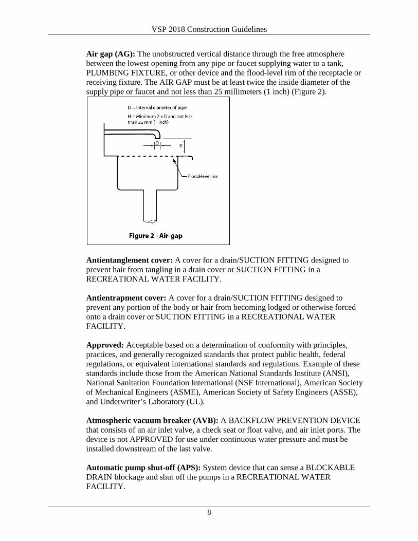
VSP 2018 Construction Guidelines
8
Air gap (AG): The unobstructed vertical distance through the free atmosphere between the lowest opening from any pipe or faucet supplying water to a tank, PLUMBING FIXTURE, or other device and the flood-level rim of the receptacle or receiving fixture. The AIR GAP must be at least twice the inside diameter of the supply pipe or faucet and not less than 25 millimeters (1 inch) (Figure 2).
Antientanglement cover: A cover for a drain/SUCTION FITTING designed to prevent hair from tangling in a drain cover or SUCTION FITTING in a RECREATIONAL WATER FACILITY. Antientrapment cover: A cover for a drain/SUCTION FITTING designed to prevent any portion of the body or hair from becoming lodged or otherwise forced onto a drain cover or SUCTION FITTING in a RECREATIONAL WATER FACILITY. Approved: Acceptable based on a determination of conformity with principles, practices, and generally recognized standards that protect public health, federal regulations, or equivalent international standards and regulations. Example of these standards include those from the American National Standards Institute (ANSI), National Sanitation Foundation International (NSF International), American Society of Mechanical Engineers (ASME), American Society of Safety Engineers (ASSE), and Underwriter’s Laboratory (UL). Atmospheric vacuum breaker (AVB): A BACKFLOW PREVENTION DEVICE that consists of an air inlet valve, a check seat or float valve, and air inlet ports. The device is not APPROVED for use under continuous water pressure and must be installed downstream of the last valve. Automatic pump shut-off (APS): System device that can sense a BLOCKABLE DRAIN blockage and shut off the pumps in a RECREATIONAL WATER FACILITY.
VSP 2018 Construction Guidelines
9
Baby-only water facility: RECREATIONAL WATER FACILITY designed for use by children in diapers or who are not completely toilet trained. This facility must have zero water depth. Control measures for this facility would be detailed in a VARIANCE. Backflow: The reversal of flow of water or other liquids, mixtures, or substances into the distribution pipes of a potable supply of water from any source or sources other than the source of POTABLE WATER supply. BACKSIPHONAGE and BACKPRESSURE are forms of backflow. Backflow prevention device: An APPROVED backflow prevention plumbing device that must be used on POTABLE WATER distribution lines where there is a direct connection or a potential CROSS-CONNECTION between the POTABLE WATER distribution system and other liquids, mixtures, or substances from any source other than the POTABLE WATER supply. Some devices are designed for use under continuous water pressure, whereas others are noncontinuous pressure types. (See also:
• ATMOSPHERIC VACUUM BREAKER [AVB]. • CONTINUOUS PRESSURE BACKFLOW PREVENTION DEVICE. • DUAL CHECK VALVE with intermediate atmospheric vent. • HOSE BIB CONNECTION VACUUM BREAKER. • PRESSURE VACUUM BREAKER ASSEMBLY. • REDUCED PRESSURE PRINCIPLE BACKFLOW PREVENTION
ASSEMBLY.) Backpressure: An elevation of pressure in the downstream piping system (by pump, elevation of piping, or steam and/or air pressure) above the supply pressure at the point of consideration that would cause a reversal of normal direction of flow. Backsiphonage: The reversal or flowing back of used, contaminated, or polluted water from a PLUMBING FIXTURE or vessel or other source into a water supply pipe as a result of negative pressure in the pipe. Black water: Wastewater from toilets, urinals, medical sinks, and other similar facilities. Blast chiller: A unit specifically designed for rapid intermediate cooling of FOOD products from 57°C (135°F) to 21°C (70°F) within 2 hours and 21°C (70°F) to 5°C (41°F) within an additional 4 hours. Blind line: Pipes closed at one end so no water passes through. Blockable drain/suction fitting: A drain or suction fitting in a RECREATIONAL WATER FACILITY that that can be completely covered or blocked by a 457

VSP 2018 Construction Guidelines
10
millimeter x 584 millimeter (18 inch x 23 inch) body-blocking element as set forth in ASME A112.19.8M. Bulkhead: A dividing wall covering an area constructed from several panels, also known as the visible part of the lining. Certified data security features: Features that ensure the values recorded by the data logger cannot be manipulated by the user. Child activity center: A facility for child-related activities where children under the age of 6 are placed to be cared for by vessel staff. Children’s pool: A pool that has a depth of 1 meter (3 feet) or less and is intended for use by children who are toilet trained. Child-size toilet: Toilets whose toilet seat height is no more than 280 millimeters (11 inches) and the toilet seat opening is no greater than 203 millimeters (8 inches). Cleaning locker: A room or cabinet specifically designed or modified for storage of cleaning EQUIPMENT such as mops, brooms, floor-scrubbing machines, and cleaning chemicals. Continuous pressure (CP) backflow prevention device: A device generally consisting of two check valves and an intermediate atmospheric vent that has been specifically designed to be used under conditions of continuous pressure (greater than 12 hours out of a 24-hour period). Coved (also coving): A concave surface, molding, or other design that eliminates the usual angles of 90° or less at deck junctures (Figures 3, 4, and 5).

VSP 2018 Construction Guidelines
11
Cross-connection: An actual or potential connection or structural arrangement between a POTABLE WATER system and any other source or system through which it is possible to introduce into any part of the POTABLE WATER system any used water, industrial fluid, gas, or substance other than the intended POTABLE WATER with which the system is supplied. Deck drain: The physical connection between decks, SCUPPERS, or DECK SINKS and the GRAY WATER or BLACK WATER systems. Deckhead: The deck overhead covering the ceiling area constructed from several panels, also known as the visible part of the ceiling. Deck sink: A sink recessed into the deck and sized to contain waste liquids from tilting kettles and pans. Disinfection: A process (physical or chemical) that destroys many or all pathogenic microorganisms, except bacterial and mycotic spores, on inanimate objects. Distillate water lines: Pipes carrying water condensed from the evaporators and that may be directed to the POTABLE WATER system. This is the VSP definition for pipe striping purposes. Double check (DC) valve assembly: A BACKFLOW PREVENTION ASSEMBLY consisting of two internally loaded, independently operating check valves located between two resilient-seated shutoff valves. These assemblies include four resilient-seated test cocks. These devices do not have an intermediate vent to the atmosphere and are not APPROVED for use on CROSS-CONNECTIONS to the POTABLE WATER system of cruise vessels. VSP accepts only vented BACKFLOW PREVENTION DEVICES.
VSP 2018 Construction Guidelines
12
Dual check valve with an intermediate atmospheric vent (DCIV): A BACKFLOW PREVENTION DEVICE with dual check valves and an intermediate atmospheric vent located between the two check valves. Drip tray: READILY REMOVABLE tray to collect dripping fluids or FOOD from FOOD dispensing EQUIPMENT. Dry storage area: A room or area designated for the storage of PACKAGED or containerized bulk FOOD that is not potentially hazardous and dry goods such as SINGLE-SERVICE ITEMS. Dual swing check valve: A nonreturn device installed on RECREATIONAL WATER FACILITY drain pipes when connected to another drainage system. This device is not APPROVED for use on the POTABLE WATER system. Easily cleanable: A characteristic of a surface that
• Allows effective removal of soil by normal cleaning methods; • Is dependent on the material, design, construction, and installation of the
surface; and • Varies with the likelihood of the surface’s role in introducing pathogenic
or toxigenic agents or other contaminants into FOOD based on the surface’s APPROVED placement, purpose, and use.
Easily movable: EQUIPMENT that
• Is PORTABLE or mounted on casters, gliders, or rollers or has a mechanical means to safely tilt it for cleaning; and
• Has no utility connection, a utility connection that disconnects quickly, or a flexible utility connection line of sufficient length that allows it to be moved for cleaning of the EQUIPMENT and adjacent area.
Food: Raw, cooked, or processed edible substance; ice; BEVERAGE; or ingredient used or intended for use or for sale in whole or in part for human consumption. Chewing gum is classified as FOOD. Food area: Includes food and BEVERAGE display, handling, preparation, service, and storage areas; warewash areas; clean EQUIPMENT storage areas; and LINEN storage and handling areas. Food-contact surface: Surfaces (food zone, splash zone) of EQUIPMENT and UTENSILS with which food normally comes in contact and surfaces from which food may drain, drip, or splash back into a food or surfaces normally in contact with food (Figures 6a and 6b).

VSP 2018 Construction Guidelines
13
Food display areas: Any area where food is displayed for consumption by passengers and/or crew. Applies to displays served by vessel staff or self-service. Food-handling areas: Any area where food is stored, processed, prepared, or served. Food preparation areas: Any area where food is processed, cooked, or prepared for service. Food service areas: Any area where food is presented to passengers or crew members (excluding individual cabin service). Food storage areas: Any area where food or food products are stored. Food transportation corridors: Areas primarily intended to move FOOD during FOOD PREPARATION, STORAGE, and SERVICE operations (e.g., service lift [elevator] vestibules to FOOD PREPARATION SERVICE and STORAGE AREAS, provision corridors, and corridors connecting preparation areas and service areas). Corridors primarily intended to move only closed beverages and packaged foods (e.g., bottled/canned beverages, crackers, chips, etc.) are not considered food transportation corridors, but the deck/BULKHEAD juncture must be coved. Excluded:
• Passenger and crew corridors, public areas, individual cabin service, and dining rooms connected to galleys.
• Food loading areas used solely for delivery of food to the vessel. Food waste system: A system used to collect, transport, and process food waste from FOOD AREAS to a waste disposal system (e.g., pulper, vacuum system). Gap: An open juncture of more than 3 millimeters (1/8 inch).

VSP 2018 Construction Guidelines
14
Gravity drain: A drain fitting used to drain the body of water in a RECREATIONAL WATER FACILITY by gravity and with no pump downstream of the fitting. Gravity drainage system: A water collection system whereby a collection tank is located between the RECREATIONAL WATER FACILITY and the suction pumps. Gray water: Wastewater from galley EQUIPMENT and DECK DRAINS, dishwashers, showers and baths, laundries, washbasins, DECK DRAINS, and recirculated RECREATIONAL WATER FACILITIES. Gray water does not include BLACK WATER or bilge water from the machinery spaces. Gutterway: See SCUPPER. Halogen: The group of elements including chlorine, bromine, and iodine used for DISINFECTION of water. Health hazard: An impairment that creates an actual hazard to the public health through poisoning or through the spread of disease. For example, water quality that creates an actual hazard to the public health through the spread of disease by SEWAGE, industrial fluids, waste, etc. (e.g., sluice machine connection). Hose bib connection vacuum breaker (HVB): A BACKFLOW PREVENTION DEVICE that attaches directly to a hose bib by way of a threaded head. This device uses a single check valve and vacuum breaker vent. It is a form of an AVB specifically designed for a hose connection. A hose bib connection vacuum breaker is not APPROVED for use under CONTINUOUS PRESSURE (e.g., when a shut-off valve is located downstream from the device). Interactive recreational water facility: An indoor or outdoor recreational water facility that includes misting, jetting, waterfalls, or sprinkling features that involve water recirculation systems that come into contact with bathers. Additional features or facilities, such as decorations or fountains, will designate the facility as an interactive RWF if there is any piping connected through the recirculation system. These facilities may be zero depth. Fully or partially enclosed water slides are considered interactive recreational water facilities. Keel laying: The date at which construction identifiable with a specific ship begins and when assembly of that ship comprises at least 50 tons or 1% of the estimated mass of all structural material, whichever is less. mg/L: Milligrams per liter, the metric equivalent of parts per million (ppm). Noncorroding: Material that maintains its original surface characteristics through prolonged influence by the use environment, FOOD contact, and normal use of cleaning compounds and sanitizing solutions.

VSP 2018 Construction Guidelines
15
Nonfood-contact surfaces (nonfood zone): All exposed surfaces, other than FOOD-CONTACT SURFACES, of EQUIPMENT located in FOOD AREAS (Figures 6a and 6b). Permeate water lines: Pipes carrying PERMEATE WATER from the reverse osmosis nit that may be directed to the POTABLE WATER SYSTEM. This is the VSP definition for pipe striping purposes. pH (potens hydrogen): The symbol for the negative logarithm of the hydrogen ion concentration, which is a measure of the degree of acidity or alkalinity of a solution. Values between 0 and 7 indicate acidity and values between 7 and 14 indicate alkalinity. The value for pure distilled water is 7, which is neutral. Plumbing fixture: A receptacle or device that
• Is permanently or temporarily connected to the water-distribution system of the vessel and demands a supply of water from the system; or
• Discharges used water, waste materials, or SEWAGE directly or indirectly to the drainage system of the vessel.
Portable: A description of EQUIPMENT that is READILY REMOVABLE or mounted on casters, gliders, or rollers; provided with a mechanical means so that it can be tilted safely for cleaning; or readily movable by one person. Potable water: Water that is halogenated and pH controlled and is intended for
• Drinking, washing, bathing, or showering; • Using in fresh water SWIMMING POOLS and WHIRLPOOL SPAS; • Using in the vessel’s hospital; • Handling, preparing, or cooking FOOD; and • Cleaning FOOD STORAGE and FOOD PREPARATION areas,
UTENSILS, and EQUIPMENT. Potable water is free from impurities in amounts sufficient to cause disease or harmful physiological effects. The water quality must conform to requirements of the World Health Organization DRINKING WATER standards. Potable water tanks: All tanks in which POTABLE WATER is stored. Pressure vacuum breaker assembly (PVB): A device consisting of an independently loaded internal check valve and a spring-loaded air inlet valve. This device is also equipped with two resilient seated gate valves and test cocks. Readily accessible: Exposed or capable of being exposed for cleaning or inspection without the use of tools. Readily removable: Capable of being detached from the main unit without the use of tools.

VSP 2018 Construction Guidelines
16
Recreational seawater: Seawater taken onboard while MAKING WAY at a position at least 12 miles at sea and routed directly to the RWFs for either sea-to-sea exchange or recirculation. Recreational water facility (RWF): A water facility that has been modified, improved, constructed, or installed for the purpose of public swimming or recreational bathing. RWFs include, but are not limited to,
• ACTIVITY POOLS. • BABY-ONLY WATER FACILITIES. • CHILDREN’S POOLS. • Diving pools. • Hot tubs. • Hydrotherapy pools. • INTERACTIVE RECREATIONAL WATER FACILITIES. • Slides. • SPA POOLS. • SWIMMING POOLS. • Therapeutic pools. • WADING POOLS. • WHIRLPOOLS.
Reduced pressure principle backflow prevention assembly (RP assembly): An assembly containing two independently acting internally loaded check valves together with a hydraulically operating, mechanically independent pressure differential relief valve located between the check valves and at the same time below the first check valve. The unit must include properly located resilient seated test cocks and tightly closing resilient seated shutoff valves at each end of the assembly. Removable: Capable of being detached from the main unit with the use of simple tools such as a screwdriver, pliers, or an open-end wrench. Safety vacuum release system (SVRS): A system capable of releasing a vacuum at a suction outlet caused by a high vacuum due to a blockage in the outlet flow. These systems shall be designed and certified in accordance with ASTM F2387-04 or ANSI/ASME A 112.19.17-2002. Sanitary seawater lines: Water lines with seawater intended for use in the POTABLE WATER production systems or in RECREATIONAL WATER FACILITIES. Scupper: A conduit or collection basin that channels liquid runoff to a DECK DRAIN. Sealant: Material used to fill SEAMS.
VSP 2018 Construction Guidelines
17
Seam: An open juncture greater than 0.8 millimeters (1/32 inch) but less than 3 millimeters (1/8 inch). Smooth:
• A FOOD-CONTACT SURFACE having a surface free of pits and inclusions with a cleanability equal to or exceeding that of (100-grit) number 3 stainless steel.
• A NONFOOD-CONTACT SURFACE of EQUIPMENT having a surface equal to that of commercial grade hot-rolled steel free of visible scale.
• Deck, BULKHEAD, or DECKHEAD that has an even or level surface with no roughness or projections to make it difficult to clean.
Spa pool: A POTABLE WATER or saltwater-supplied pool with temperatures and turbulence comparable to a WHIRLPOOL SPA.
• Depth of more than 1 meter (3 feet) and • Tub volume of more than 6 tons of water.
Spill-resistant vacuum breaker (SVB): A specific modification to a PRESSURE VACUUM BREAKER ASSEMBLY to minimize water spillage. Spray pad: Play and water contact area designed to have no standing water. Suction fitting: A fitting in a RECREATIONAL WATER FACILITY under direct suction through which water is drawn by a pump. Swimming pool: A RECREATIONAL WATER FACILITY greater than 1 meter in depth. This does not include SPA POOLS that meet this depth. Technical water: Water that has not been chlorinated or pH controlled on board the vessel and that originates from a bunkering or condensate collection process, or seawater processed through the evaporators or reverse osmosis plant and is intended for storage and use in the technical water system. Temperature-measuring device (TMD): A thermometer, thermocouple, thermistor, or other device that indicates the temperature of FOOD, air, or water and is numerically scaled in Celsius and/or Fahrenheit. Turnover: The circulation, through the recirculation system, of a quantity of water equal to the pool volume. Unblockable drain/suction fitting: A drain or SUCTION FITTING in a RECREATIONAL WATER FACILITY that cannot be completely covered or blocked by a 457 millimeters x 584 millimeters (18 inches x 23 inches) body-blocking element and that is rated by the test procedures or by the appropriate calculation in accordance with ASME A112.19.8M.

VSP 2018 Construction Guidelines
18
Utility sink: Any sink located in FOOD SERVICE AREAS not intended for handwashing and/or WAREWASHING. Wading pool: RECREATIONAL WATER FACILITY with a maximum depth of less than 1 meter. Whirlpool spa: A freshwater or seawater pool equipped with either water or air jets and designed to operate at a minimum temperature of 32°C (90°F) and a maximum temperature of 40°C (104°F).
5.3 Acronyms AG AIR GAP ANSI American National Standards Institute ASHRAE American Society of Heating, Refrigeration and Air-Conditioning
Engineers ASME American Society of Mechanical Engineers ASSE American Society of Safety Engineers ASTM American Society for Testing and Materials AVB ATMOSPHERIC VACUUM BREAKER C Celsius CDC Centers for Disease Control and Prevention CP continuous pressure F Fahrenheit FDA U.S. Food and Drug Administration GRT gross registered tonnage HVB HOSE-BIB CONNECTED VACUUM BREAKER IEC International Electrical Code IMO International Maritime Organization IPC International Plumbing Code ISO International Standards Organization MARPOL International Convention for the Prevention of Pollution from Ships MG/L MILLIGRAMS PER LITER NCEH National Center for Environmental Health NSF International National Sanitation Foundation International ORP oxidation reduction potential pH POTENS HYDROGEN PHS U.S. Public Health Service (also USPHS) ppm parts per million RP ASSEMBLY REDUCED PRESSURE PRINCIPLE BACKFLOW
PREVENTION ASSEMBLY RWF RECREATIONAL WATER FACILITY SOLAS safety of life-at-sea UL Underwriter’s Laboratories UV ultraviolet light VSP Vessel Sanitation Program WHO World Health Organization

VSP 2018 Construction Guidelines
19
6.0 General Facilities Requirements
6.1 Size and Flow Many factors determine and influence the size of rooms and work areas and the flow of FOOD through a vessel. Those factors can include the vessel size, number of passengers and crew, types of FOODS and menus, number of meals and mealtimes, service or presentation of meals, itinerary, and vessel owner’s experience. In general, FOOD STORAGE, PREPARATION, SERVICE and TRANSPORTATION areas; warewashing areas; and waste management areas must be sized to accommodate the vessel’s full capacity of passengers and crew. Bulk FOOD STORAGE AREAS or provision rooms (e.g., frozen stores, refrigerated stores, and DRY STORAGE AREAS) must be sized to prevent the storage of bulk FOODS in provisions passageways unless the passageways are specifically designed to meet provision room standards (section 15.0). Refrigeration and hot-FOOD holding facilities, including temporary storage facilities, must be available for all FOOD PREPARATION and SERVICE areas and for FOODS being transported to remote areas.
6.1.1 Food Flow Arrange the flow of FOOD through a vessel in a logical sequence that eliminates or minimizes cross-traffic or backtracking. Provide a clear separation of clean and soiled operations. When a common corridor is used for movement of both clean and soiled operations, the minimum distance from BULKHEAD to BULKHEAD must be considered. Within a galley, the standard separation between clean and soiled operations must be a minimum of 2 meters (6½ feet). For smaller galleys (e.g., specialty, bell box) the minimum distance will be assessed during the plan review. Additionally, common corridors for size and flow of galley operations will be reviewed during the plan review. Provide an orderly flow of FOOD from the suppliers at dockside through the FOOD STORAGE, PREPARATION, and finishing areas to the SERVICE areas and, finally, to the waste management area. The goals are to reduce the risk for cross-contamination, prepare and serve FOOD rapidly in accordance with strict time and temperature-control requirements, and minimize handling. Provide a size profile for each FOOD AREA, including provisions, preparation rooms, galleys, pantries, warewash, garbage processing area, and storage. The size profile shows the square meters of space designated for that area. Where possible, VSP will visit the profile vessel(s) to verify the capacity during operational inspections. The size profile must be an established standard for each cruise line based on the line’s review of the area size for the same FOOD AREA in its existing vessels. As the ship size and passenger and crew totals change, there must be a proportional change in each FOOD AREA size based

VSP 2018 Construction Guidelines
20
on the profile to ensure the service needs are met for each area. Size evaluations of FOOD AREAS will incorporate seating capacity and staffing, service, and equipment needs. During the plan review process VSP evaluates the size of a particular room or area and the flow of FOOD through the vessel to those rooms or areas. VSP will also use the results of operational inspections to review the size profiles submitted by individual cruise lines.
6.2 Equipment Requirements
6.2.1 Galleys The equipment in sections 6.2.1.1 through 6.2.1.12 is required in galleys depending on the level and type of service. This equipment may be recommended for other areas.
6.2.1.1 Blast Chillers Incorporate BLAST CHILLERS into the design of passenger and crew galleys. More than one unit may be necessary depending on the size of the vessel and the distances between the BLAST CHILLERS and the storage and service areas.
6.2.1.1.1 Size and Type The size and type of BLAST CHILLERS installed for each FOOD PREPARATION AREA are based on the concept/menu, operational requirements to satisfy that menu, and volume of FOOD requiring cooling.
6.2.1.2 Utility Sinks Include food preparation UTILITY SINKS in all meat, fish, and vegetable preparation rooms; in cold pantries or garde mangers; and in any other areas where personnel wash or soak FOOD.
6.2.1.2.1 Vegetable Washing An automatic vegetable washing machine may be used in addition to FOOD PREPARATION UTILITY SINKS in vegetable preparation rooms.
6.2.1.3 Food Storage Include storage cabinets, shelves, or racks for FOOD products and equipment in FOOD STORAGE, PREPARATION, and SERVICE AREAS, including bars and pantries.
6.2.1.4 Tables, Carts, or Pallets Locate fixed or PORTABLE tables, carts, or pallets in areas where FOOD or ice is dispensed from cooking equipment, such as from soup kettles, steamers, braising pans, tilting pans, or ice storage bins.

VSP 2018 Construction Guidelines
21
6.2.1.5 Storage for Large Utensils Include a storage cabinet or rack for large utensils such as ladles, paddles, whisks, and spatulas and provide for vertical storage of cutting boards.
6.2.1.6 Knife Storage Include knife lockers or other designated knife storage facilities (e.g., drawers) that are EASILY CLEANABLE and meet FOOD-CONTACT standards.
6.2.1.7 Waiter Trays Include storage areas, cabinets, or shelves for waiter trays.
6.2.1.8 Dish Storage Include dishware lowerators or similar dish storage and dispensing cabinets.
6.2.1.9 Glass Rack Include glass rack storage shelving.
6.2.1.10 Preparation Counters Include work counters or food preparation counters that provide sufficient work space.
6.2.1.11 Drinking Fountains Include drinking fountains that allow for hands-free operation and without a filling spout in FOOD AREAS.
6.2.1.12 Cleaning Lockers Include CLEANING LOCKERS (see section 20.1 for specific CLEANING LOCKER construction requirements).
6.2.2 Warewashing Sinks Equip the main galley, crew galley, and lido service area/galley pot washing areas with a three-compartment sink and prewash station or a four-compartment sink with an insert pan and an overhead spray. Install sinks with compartments large enough to accommodate the largest piece of equipment (pots, tableware, etc.) used in their designated serving areas. An automatic warewash machine may be added but cannot be substituted for a three- or four-compartment sink. Provide additional three-compartment sinks with prewash stations or four-compartment sinks with insert pans and overhead spray in heavy-use areas. Heavy-use areas may include pastry/bakery, butcher shop, buffet pantry, and other preparation areas where the size of the facility or the location makes the

VSP 2018 Construction Guidelines
22
use of a central pot washing area impractical. Refer to section 18.0 for additional warewashing requirements.
6.2.3 Warewashing Access Equip all FOOD PREPARATION AREAS with easy access to a three-compartment sink or a warewashing machine with an adjacent dump sink and prewash hose. Refer to section 18.0 for additional warewashing requirements.
6.2.4 Drip Trays or Drains, Beverages Furnish beverage dispensing equipment with READILY REMOVABLE DRIP TRAYS or built-in drains in the tabletop. Furnish bulk milk dispensers with READILY REMOVABLE DRIP TRAYS.
6.2.5 Drip Trays, Condiments Provide READILY REMOVABLE DRIP TRAYS for condiment-dispensing equipment.
6.2.6 Equipment Storage Areas Design storage areas to accommodate all equipment and utensils used in FOOD PREPARATION AREAS (for example, ladles and cutting blades).
6.2.7 Deck Drainage Ensure that the design of installed equipment directs FOOD and wash water drainage into a DECK DRAIN, SCUPPER, or DECK SINK, and not onto a deck.
6.2.8 Utility Sink Provide a UTILITY SINK in areas such as beverage stations and bars where it is necessary to refill serving pitchers or discard beverages.
6.2.9 Dipper Wells For hand-scooped ice cream, sherbet, or similar products, provide dipper wells with running water and proper drainage.
6.2.10 Doors or Closures Provide tight-fitting doors or other protective closures for ice bins, FOOD DISPLAY cases, and other FOOD and ice holding units to prevent contamination of stored products.
6.2.11 Countertop Openings and Rims Protect countertop openings and rims of FOOD cold tops, bains-marie, ice wells, and other drop-in type FOOD and ice holding units with a raised integral edge (marine edge) or rim of at least 5 millimeters (3/16 inch) above the counter

VSP 2018 Construction Guidelines
23
level around the opening.
6.2.12 Insect-Control Devices Insect-control devices that electrocute or stun flying insects are not permitted in FOOD AREAS. Do not install insect control devices such as insect light traps over FOOD STORAGE, FOOD PREPARATION AREAS, FOOD SERVICE stations, or clean EQUIPMENT.
6.3 Equipment Surfaces
6.3.1 Materials Ensure material used for FOOD-CONTACT SURFACES and exposed NONFOOD-CONTACT SURFACES is SMOOTH, durable, and NONCORRODING. These surfaces must be EASILY CLEANABLE and designed without unnecessary edges, projections, or crevices.
6.3.2 Approved Materials Use only materials APPROVED for contact with FOOD on FOOD-CONTACT SURFACES.
6.3.2.1 Surfaces Make all FOOD-CONTACT SURFACES SMOOTH (with no sharp edges), durable, NONCORRODING, EASILY CLEANABLE, READILY ACCESSIBLE, and maintainable.
6.3.2.2 Corners Provide COVED and seamless corners. Form external corners and angles with a sufficient radius to permit proper drainage and without sharp edges.
6.3.2.3 Sealants Use only SEALANTS APPROVED for FOOD-CONTACT SURFACES (certified to ANSI/NSF Standard 51, or equivalent criteria) on FOOD-CONTACT SURFACES and FOOD splash zone surfaces. Avoid excessive use of SEALANT.
6.3.3 Nonfood-Contact Surfaces Use durable and NONCORRODING material for NONFOOD-CONTACT SURFACES.
6.3.3.1 Easily Cleanable Design NONFOOD-CONTACT SURFACES so that they are SMOOTH and EASILY CLEANABLE. Ensure that NONFOOD-CONTACT SURFACES are ACCESSIBLE for cleaning and maintenance.

VSP 2018 Construction Guidelines
24
6.3.3.2 No Sharp Corners Ensure that NONFOOD-CONTACT SURFACES subject to FOOD or beverage spills have no sharp internal corners and angles. Examples of these areas are waiter station work surfaces, beverage stations, technical compartments with drain lines, mess room soiled drop-off stations, and bus stations.
6.3.3.3 Compatible Metals Use compatible metals to minimize corrosion due to galvanic action or to provide effective insulation between dissimilar metals to protect them from corrosion.
6.4 Bulkheads, Deckheads, and Decks
6.4.1 Exposed Fasteners Do not use exposed fasteners in BULKHEAD and DECKHEAD construction.
6.4.2 Seams and Penetrations Seal all SEAMS between adjoining BULKHEAD panels and adjoining DECKHEAD panels and between BULKHEAD and DECKHEAD panels.
6.4.2.1 Seal Seams Seal SEAMS greater than 0.8 millimeters (1/32 inch), but less than 3 millimeters (1/8 inch), with an appropriate SEALANT or appropriate profile strips.
6.4.2.2 Cover Gaps Cover all GAPS greater than 3 millimeters (1/8 inch) with appropriate profile strips.
6.4.2.3 Seal Penetrations Seal all BULKHEAD, DECKHEAD, and deck penetrations through which pipes or other conduits pass, including those inside technical compartments. Use durable and NONCORRODING collars where GAPS are greater than 3 millimeters (1/8 inch).
6.4.3 Bulkheads Reinforce all BULKHEADS sufficiently to prevent buckling or to prevent the BULKHEAD from becoming detached under normal operating conditions.
6.4.4 Penetrations Weld door penetrations penetrations around fire doors, in thresholds, and in BULKHEAD openings so there are no exposed voids. Ensure locking/latch pins insert into closed locking pin recesses. See Figure 7.

VSP 2018 Construction Guidelines
25
6.4.5 Deck Coving Install COVING as an integral part of the deck and BULKHEAD interface and at the juncture between decks and equipment foundations.
6.4.5.1 Radius Ensure COVING has at least a 9.5-millimeter (3/8-inch) radius or open design (>90°). Additionally, a single bent piece of stainless steel can be used as COVING. See COVING definition (Figures 3 and 4).
6.4.5.2 Materials Provide COVING that is hard, durable, EASILY CLEANABLE, and of sufficient thickness to withstand normal wear.
6.4.5.3 Fasten Securely fasten COVING.
6.4.6 Deck Material Use deck material that is hard, durable, EASILY CLEANABLE, nonskid, and nonabsorbent. Vinyl or linoleum deck coverings are not acceptable in FOOD AREAS. However, vinyl or linoleum deck coverings may be used in areas where only table linens are stored.
6.4.7 Compatible Metals Use compatible metals to minimize corrosion due to galvanic action or to provide effective insulation between dissimilar metals to protect them from corrosion.
VSP 2018 Construction Guidelines
26
6.5 Deck Drains, Deck Sinks, and Scuppers
6.5.1 Material Construct DECK DRAINS, SCUPPERS, and DECK SINKS from stainless steel.
6.5.1.1 Other Requirements Ensure DECK DRAINS, SCUPPERS, and DECK SINKS have SMOOTH finished surfaces, are ACCESSIBLE for cleaning, and are designed to drain completely.
6.5.3 Cover Grates Construct SCUPPER and DECK SINK cover grates from stainless steel or other materials that
• Meet the requirements for a SMOOTH, EASILY CLEANABLE surface, • Are strong enough to maintain the original shape, and • Have no sharp edges.
6.5.2.1 Other Requirements Provide SCUPPER and DECK SINK cover grates that are tight-fitting, READILY REMOVABLE for cleaning, and uniform in length where practical (e.g., 1 meter or 40 inches) so that they are interchangeable.
6.5.3 Location Place DECK DRAINS and DECK SINKS in low-traffic areas such as in front of soup kettles, boilers, tilting pans, or braising pans.
6.5.4 Sizing Size DECK DRAINS, SCUPPERS, and sinks to eliminate spillage and overflow to adjacent deck surfaces.
6.5.5 Deck Drainage Provide sufficient deck drainage and design deck and SCUPPER drain lines in all FOOD SERVICE and warewash areas to prevent liquids from pooling on the decks. Do not use DECK SINKS as substitutes for DECK DRAINS.
6.5.6 Cross-Drain Connections Provide cross-drain connections to prevent pooling and spillage from the SCUPPER when the vessel is listing.
6.5.7 Coaming If a nonremovable coaming is provided around a DECK DRAINS, ensure the juncture with the deck is COVED. Integral COVING is not required.

VSP 2018 Construction Guidelines
27
6.6 Ramps
6.6.1 Installation Install ramps over thresholds and ensure they are easily REMOVABLE or sealed in place. Slope ramps for easy trolley roll-in and roll-out. Ensure ramps are strong enough to maintain their shape. If ramps over SCUPPER covers are built as an integral part of the SCUPPER system, construct them of SMOOTH, durable, and EASILY CLEANABLE materials.
6.7 Gray and Black Water Drain Lines
6.7.1 Installation Limit the installation of drain lines that carry BLACK WATER or other liquid wastes directly overhead or horizontally through spaces used for FOOD PREPARATION or STORAGE. This limitation includes areas for washing or storing utensils and equipment (e.g., in bars, in deck pantries, and over buffet counters). If installation of waste lines is unavoidable in these areas,
• Sleeve weld or butt weld steel piping. • Heat fuse or chemically weld plastic piping.
For SCUPPER lines, factory assembled transition fittings for steel to plastic pipes are allowed when manufactured per ASTM F1973 or equivalent standard. Do not use push-fit or press-fit piping over these areas.
7.0 General Hygiene Facilities Requirements for Food Areas
7.1 Handwashing Stations This section applies to self-service and served candy shops where employees serve candy, refill self-service containers, etc.
7.1.1 Potable Water Provide hot and cold POTABLE WATER to all handwashing sinks. Equip handwashing sinks to provide water at a temperature between 38°C (100°F) and 49°C (120°F) through a mixing valve or combination faucet.
7.1.2 Construction Construct handwashing sinks of stainless steel in FOOD AREAS. Handwashing sinks in FOOD SERVICE AREAS and bars may be constructed of a similar, SMOOTH, durable material.

VSP 2018 Construction Guidelines
28
7.1.3 Supplies Provide handwashing stations that include a soap dispenser, paper towel dispenser, corrosion-resistant waste receptacle, and, where necessary, splash panels to protect the following:
• Adjoining equipment. • Clean utensils. • FOOD STORAGE. • FOOD PREPARATION surfaces.
If attached to the BULKHEAD, permanently seal soap dispensers, paper towel dispensers, and waste towel receptacles or make them REMOVABLE for cleaning. Air hand dryers are not permitted.
7.1.4 Dispenser Locations Install soap dispensers and paper towel dispensers so that they are not over adjoining equipment, clean utensil storage, FOOD STORAGE, FOOD PREPARATION surfaces, bar counters, or water fountains. For a multiple-station sink, ensure that there is a soap dispenser within 380 millimeters (15 inches) of each faucet and a paper towel dispenser within 760 millimeters (30 inches) of each faucet.
7.1.5 Dispenser Installation Install paper towel dispensers a minimum of 450 millimeters (18 inches) above the deck (as measured from the lower edge of the dispenser).
7.1.6 Installation Specifications Install handwash sinks a minimum of 750 millimeters (30 inches) above the deck, as measured at the top edge of the basin, so employees do not have to reach excessively to wash their hands. Install counter-mounted handwash sinks a minimum of 600 millimeters (24 inches) above the deck, as measured at the counter level. The minimum size of the handwash sink basin must be 300 millimeters (12 inches) in length and 300 millimeters (12 inches) in width. The diameter of round basins must be at least 300 millimeters (12 inches). Additionally, the minimum distance from the bottom of the water tap to the bottom of the basin must be 200 millimeters (8 inches).
7.1.7 Locations Locate handwashing stations throughout FOOD-HANDLING, PREPARATION, and warewash areas so that no employee must walk more than 8 meters (26 feet) to reach a station or pass through a normally closed door that requires touching a handle to open.
VSP 2018 Construction Guidelines
29
7.1.7.1 Food-Dispensing Waiter Stations Provide a handwashing station at food-dispensing waiter stations (e.g., soups, ice, etc.) where the staff do not routinely return to an area with a handwashing station.
7.1.7.2 Food-Handling Areas Provide a handwashing station in provision areas where bulk raw FOODS are handled by provisioning staff.
7.1.7.3 Crew Buffets Provide at least one handwashing station for every 100 seats (e.g., 1–100 seats = one handwashing station, 101–200 seats = two handwashing stations, etc.). Locate stations near the entrance of all officer/staff/crew mess areas where FOOD SERVICE lines are “self-service.”
7.1.7.4 Soiled Dish Drop-Off Install handwashing stations at the soiled dish drop-off area(s) in the main galley, specialty galleys, and pantries for employees bringing soiled dishware from the dining rooms or other FOOD SERVICE AREAS to prevent long waiting lines at handwashing stations. Provide one sink or one faucet on a multiple-station sink for every 10 wait staff who handle clean items and are assigned to a FOOD SERVICE AREA during maximum capacity. During the plan review, VSP will evaluate work assignments for wait staff to determine the appropriate number of handwashing stations.
7.1.8 Faucet Handles Install easy-to-operate sanitary faucet handles (e.g., large elephant-ear handles, foot pedals, knee pedals, or electronic sensors) on handwashing sinks in FOOD AREAS. If a faucet is self-closing, slow-closing, or metering, provide a water flow of at least 15 seconds without the need to reactivate the faucet.
7.1.9 Signs Install permanent signs in English and other appropriate languages stating “wash hands often,” “wash hands frequently,” or similar wording.
7.2 Bucket-Filling Station
7.2.1 Location Provide at least one bucket-filling station in each area of the galleys (e.g., cold galley, hot galley, bakery, etc.) and in FOOD STORAGE and FOOD PREPARATION AREAS.

VSP 2018 Construction Guidelines
30
7.2.2 Mixing Valve Supply hot and cold POTABLE WATER through a mixing valve to a faucet with the appropriate BACKFLOW protection at each bucket-filling station.
7.2.3 Deck Drainage Provide appropriate deck drainage (e.g., SCUPPER or sloping deck to DECK DRAIN) under all bucket-filling stations to eliminate any pooling of water on the decks below the bucket-filling station.
7.3 Crew Public Toilet Rooms for Food Service Employees
7.3.1 Location and Number Install at least one employee toilet room in close proximity to the work area of all FOOD PREPARATION AREAS. [Beverage-only service bars are excluded.] Provide one toilet per 25 employees and provide separate facilities for males and females if more than 25 employees are assigned to a FOOD PREPARATION AREA (excluding wait staff). This refers to the shift with the maximum number of FOOD employees excluding wait staff. Urinals may be installed but do not count toward the toilet/employee ratio.
7.3.1.1 Main Galleys and Crew Galleys For main galleys and crew galleys, locate toilet rooms inside the FOOD PREPARATION AREA or in a passageway immediately outside the area. If a main galley has multiple levels and there is stairwell access between the galleys, toilet rooms may be located near the stairwell within one deck above or below.
7.3.1.2 Other Food Service Outlets For other FOOD SERVICE outlets (lido galley, specialty galley, etc.), do not locate toilet rooms more than two decks above or below and within the distance of a fire zone. Do not locate toilet rooms more than one fire zone away if on the same deck (they should be within the same fire zone or an adjacent fire zone). If more than one FOOD SERVICE outlet is located on the same deck, the toilet room may be located on the same deck between the outlets and within two fire zones of each outlet.
7.3.1.3 Provision Areas For preparation rooms in provision areas, use the distance requirement described in 7.3.1.2 to locate toilet rooms.
7.3.2 Ventilation and Handwashing Install exhaust ventilation and handwashing facilities in each toilet room. Air hand dryers are not permitted in these toilet rooms. Install a permanent sign in English, and other languages where appropriate, stating the exact wording:

VSP 2018 Construction Guidelines
31
“WASH HANDS AFTER USING THE TOILET.” Locate this sign on the BULKHEAD adjacent to the main toilet room door or on the main door inside the toilet room.
7.3.3 Hands-Free Exit Ensure hands-free exit for toilet rooms, as described in section 36.2. Ensure handwashing facilities have sanitary faucet handles as in section 7.1.8.
7.3.4 Doors Install tight-fitting, self-closing doors.
7.3.5 Decks Construct decks of hard, durable materials and provide COVING at the BULKHEAD-deck juncture.
7.3.6 Deckheads and Bulkheads Install EASILY CLEANABLE DECKHEADS and BULKHEADS.
8.0 Equipment Placement and Mounting
8.1 Seal Seal counter-mounted equipment that is not PORTABLE to the BULKHEAD, tabletop, countertop, or adjacent equipment. If the equipment is not sealed, provide sufficient, unobstructed space for cleaning around, behind, and between fixed equipment. The space provided is dependent on the distance from either a position directly in front or from either side of the equipment to the farthest point requiring cleaning as described in sections 8.1.1 through 8.1.4. These requirements do not apply to open racks, other equipment of open design, or PORTABLE equipment. See also Figures 8a through 8d.
8.1.1 Cleaning Distance Less Than 600 Millimeters (24 Inches) A cleaning distance of less than 600 millimeters (24 inches) requires an unobstructed space of 150 millimeters (6 inches).
8.1.2 Cleaning Distance Between 600 Millimeters (24 Inches) and 1,200 Millimeters (48 Inches)
A cleaning distance between 600 millimeters (24 inches) and 1,200 millimeters (48 inches) requires an unobstructed space of 200 millimeters (8 inches).
8.1.3 Cleaning Distance Between 1,200 Millimeters (48 Inches) and 1,800 Millimeters (72 Inches)
A cleaning distance between 1,200 millimeters (48 inches) and 1,800 millimeters (72 inches) requires an unobstructed space of 300 millimeters (12 inches).

VSP 2018 Construction Guidelines
32
8.1.4 Cleaning Distance Greater Than 1,800 Millimeters (72 Inches) A cleaning distance greater than 1,800 millimeters (72 inches) requires an unobstructed space of 460 millimeters (18 inches).

VSP 2018 Construction Guidelines
33
Distance To Be Cleaned Unobstructed Space Less than 600 millimeters (24 inches) 150 millimeters (6 inches) Between 600 millimeters (24 inches) and 1,200 millimeters (48 inches)
200 millimeters (8 inches)
Between 1,200 millimeters (48 inches) and 1,800 millimeters (72 inches)
300 millimeters (12 inches)
More than 1,800 millimeters (72 inches) 460 millimeters (18 inches)
8.1.5 Cleaning Distance If the unobstructed cleaning space includes a corner, the cleaning distance must be treated separately in two sections. Treat the farther space behind the equipment separately according to sections 8.1.1 through 8.1.4. The closer space

VSP 2018 Construction Guidelines
34
has to be minimum of 300 millimeters (12 inches). For cleaning distance greater than 1,800 millimeters (72 inches), the closer space has to be treated according to section 8.1.4. See Figure 8d.
8.2 Seal or Elevate Seal equipment that is not PORTABLE to the deck or elevate it on legs that provide at least a 150-millimeter (6-inch) clearance between the deck and the equipment. If no part of the equipment is more than 150 millimeters (6 inches) from the point of cleaning access, the clearance space may be only 100 millimeters (4 inches). This includes vending and dispensing machines in FOOD AREAS, including mess rooms. Exceptions to the equipment requirements may be granted if there are no barriers to cleaning (e.g., equipment such as waste handling systems and warewashing machines with pipelines, motors, and cables) and a 150-millimeter (6-inch) clearance from the deck may not be practical.
8.2.1 Deck Mounting Continuous weld all equipment that is not PORTABLE to stainless steel pads or plates on the deck. Ensure the welds have SMOOTH edges, rounded corners, and no GAPS.
8.2.2 Adhesives Attach deck-mounted equipment as an integral part of the deck surface with glue, epoxy, or other durable, APPROVED adhesive product. Ensure that the attached surfaces are SMOOTH and EASILY CLEANABLE.
8.3 Deckhead Clearance Provide a minimum of at least 150 millimeters (6 inches) between equipment and DECKHEADS. If this clearance cannot be achieved, extend the equipment to the DECKHEAD panels and seal appropriately.
8.4 Foundation or Coaming Provide a sealed-type foundation or coaming for equipment not mounted on legs. Do not allow equipment to overhang the foundation or coaming by more than 100 millimeters (4 inches). Completely seal any overhanging equipment along the bottom (Figure 9). Mount equipment on a foundation or coaming at least 100 millimeters (4 inches) above the finished deck. Use cement, hard SEALANT, or continuous weld to seal equipment to the foundation or coaming.

VSP 2018 Construction Guidelines
35
8.5 Counter-Mounted Equipment Seal counter-mounted equipment, unless PORTABLE, to the countertop or mount it on legs.
8.5.1 Leg Length Leg length depends on the horizontal distance of the table top under the equipment from either end to the farthest point requiring cleaning (see table below). Horizontal Distance (Depth) Equipment Leg Length More than 750 millimeters (30 inches)
At least 150 millimeters (6 inches)
500 to 750 millimeters (20 to 30 inches)
At least 100 millimeters (4 inches)
75 to 500 millimeters (3 to 20 inches)
At least 75 millimeters (3 inches)
Less than 75 millimeters (3 inches)
50 millimeters (2 inches)
9.0 Fasteners and Requirements for Securing and Sealing Equipment
9.1 Food-Contact Surfaces
9.1.1 Attach Attach all FOOD-CONTACT SURFACES or connections from FOOD-CONTACT SURFACES to adjacent splash zones to ensure a seamless COVED corner.

VSP 2018 Construction Guidelines
36
Reinforce all BULKHEADs, DECKHEADS, or decks receiving such attachments.
9.1.2 Fasteners Use low profile, nonslotted, NONCORRODING, and easy-to-clean fasteners on FOOD-CONTACT SURFACES and in splash zones. The use of exposed slotted screws, Phillips head screws, or pop rivets in these areas is prohibited.
9.2 Nonfood-Contact Surfaces
9.2.1 Seal Seal equipment SEAMS with an appropriate SEALANT (see SEAM definition). Avoid excessive use of SEALANT. Use stainless steel profile strips on surfaces exposed to extreme temperatures (e.g., freezers, cook tops, grills, and fryers) or for GAPS greater than 3 millimeters (1/8 inch). Do not use SEALANTS to close GAPS.
9.2.2 Fasteners Construct slotted or Phillips head screws, pop rivets, and other fasteners used in NONFOOD-CONTACT AREAS of NONCORRODING materials.
9.3 Use of Sealants
9.3.1 Approved Use APPROVED (certified to ANSI/NSF Standard 51 or equivalent criteria) FOOD grade SEALANTS on FOOD-CONTACT SURFACES. Avoid excessive use of SEALANT. Once cured, SEALANTS must be SMOOTH, semihard or hard, durable, and easy to clean. [Soft SEALANTS can be used in ice machines.] Provide product manufacturers’ literature and certification listing for SEALANTS used.
10.0 Latches, Hinges, and Handles
10.1 Durable, Noncorroding, and Easily Cleanable Use durable, NONCORRODING, and EASILY CLEANABLE built-in equipment latches, hinges, and handles. Do not use piano hinges in FOOD-CONTACT SURFACES.
VSP 2018 Construction Guidelines
37
11.0 Gaskets
11.1 Materials Use SMOOTH, nonabsorbent, nonporous materials for equipment gaskets in reach-in refrigerators, steamers, ice bins, ice cream freezers, and similar equipment.
11.2 Exposed Surfaces Close and seal exposed surfaces of gaskets at their ends and corners.
11.3 Removable Use REMOVABLE door gaskets in refrigerators, freezers, BLAST CHILLERS, and similar equipment.
11.4 Fasteners Follow the requirements in section 9.0 when using fasteners to install gaskets.
12.0 Equipment Drain Lines
12.1 Connections Connect drain lines to the appropriate waste system by means of an AIR GAP or AIR-BREAK from all fixtures, sinks, appliances, compartments, refrigeration units, or other equipment used, designed for, or intended to be used in the preparation, processing, storage, or handling of FOOD, ice, or drinks. Ensure the AIR GAP or AIR-BREAK is easily ACCESSIBLE for inspection and cleaning.
12.2 Construction Materials Use stainless steel or other durable, NONCORRODING, and EASILY CLEANABLE rigid or flexible material in the construction of drain lines. Do not use ribbed, braided, or woven materials in areas subject to splash or soiling unless coated with a SMOOTH, durable, and EASILY CLEANABLE material.
12.3 Size Size drain lines appropriately, with a minimum interior diameter of 25 millimeters (1 inch) for custom-built equipment.
12.4 Walk-In Refrigerators and Freezers Slope walk-in refrigerator and freezer evaporator drain lines and extend them through the BULKHEAD or deck.
12.4.1 Evaporator Drain Lines Direct walk-in refrigerator and freezer evaporator drain lines through an ACCESSIBLE AIR-BREAK to a deck SCUPPER or drain below the deck level or to a SCUPPER outside the unit.
VSP 2018 Construction Guidelines
38
12.5 Deck Drains and Scuppers Direct drain lines from DECK DRAINS and SCUPPERS through an indirect connection to the wastewater system for any room constructed to store FOOD, clean equipment, single-use and single-service articles, and clean FOOD service linen.
12.6 Horizontal Distance Install drain lines to minimize the horizontal distance from the source of the drainage to the discharge.
12.7 Vertical Distance Install horizontal drain lines at least 100 millimeters (4 inches) above the deck and slope them to drain.
12.8 Food Equipment Drain Lines All drain lines (except condensate drain lines) from hood washing systems, cold-top tables, bains-marie, dipper wells, UTILITY SINKS, and warewashing sinks or machines must meet the criteria in sections 12.8.1 through 12.8.4:
12.8.1 Length Lines must be less than 1,000 millimeters (40 inches) in length and free of sharp angles or corners if designed to be cleaned in place by a brush.
12.8.2 Cleaning Lines must be READILY REMOVABLE for cleaning if they are longer than 1,000 millimeters (40 inches).
12.8.3 Extend Vertically Extend fixed equipment drain lines vertically to a SCUPPER or DECK DRAIN when possible. If not possible, keep the horizontal distance of the line to a minimum.
12.8.4 Air-Break Handwashing sinks, mop sinks, and drinking fountains are not required to drain through an AIR-BREAK.
13.0 Electrical Connections, Pipelines, Service Lines, and Attached Equipment
13.1 Encase Encase electrical wiring from permanently installed equipment in durable and EASILY CLEANABLE material. Do not use ribbed or woven stainless steel electrical conduit where it is subject to splash or soiling unless it is encased in EASILY CLEANABLE plastic or similar EASILY CLEANABLE material. Do not use ribbed, braided, or woven conduit.
VSP 2018 Construction Guidelines
39
13.2 Install or Fasten For equipment that is not permanently mounted, install or fasten service lines in a manner that prevents the lines from contacting decks or countertops.
13.3 Mounted Equipment Tightly seal BULKHEAD or DECKHEAD-mounted equipment (phones, speakers, electrical control panels, outlet boxes, etc.) with the BULKHEAD or DECKHEAD panels. Do not locate such equipment in areas exposed to FOOD splash.
13.4 Seal Penetrations Tightly seal any areas where electrical lines, steam or water pipelines, etc., penetrate the panels or tiles of the deck, BULKHEAD, or DECKHEAD, including inside technical spaces located above or below equipment or work surfaces. Seal any openings or voids around the electrical lines or the steam or water pipelines and the surrounding conduit or pipelines.
13.5 Enclose Pipelines Enclose steam and water pipelines to kettles and boilers in stainless steel cabinets or position the pipelines behind BULKHEAD panels. Minimize the number of exposed pipelines. Cover any exposed insulated pipelines with stainless steel or other durable, EASILY CLEANABLE material.
14.0 Hood Systems
14.1 Warewashing Install canopy exhaust hood or direct duct exhaust systems over warewashing equipment (except undercounter warewashing machines) and over three-compartment sinks in pot wash areas where hot water is used for sanitizing.
14.1.1 Direct Duct Exhaust Directly connect warewashing machines that have a direct duct exhaust to the hood exhaust trunk.
14.1.2 Overhang Provide canopy exhaust hoods over warewashing equipment or three-compartment sinks to have a minimum 150-millimeter (6-inch) overhang from the steam outlet to capture excess steam and heat and prevent condensate from collecting on surfaces (Figure 10).
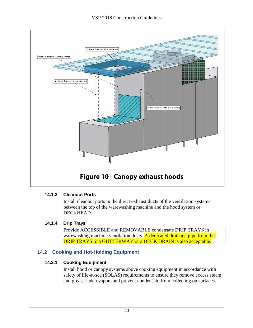
VSP 2018 Construction Guidelines
40
14.1.3 Cleanout Ports Install cleanout ports in the direct exhaust ducts of the ventilation systems between the top of the warewashing machine and the hood system or DECKHEAD.
14.1.4 Drip Trays Provide ACCESSIBLE and REMOVABLE condensate DRIP TRAYS in warewashing machine ventilation ducts. A dedicated drainage pipe from the DRIP TRAYS to a GUTTERWAY or a DECK DRAIN is also acceptable.
14.2 Cooking and Hot-Holding Equipment
14.2.1 Cooking Equipment Install hood or canopy systems above cooking equipment in accordance with safety of life-at-sea (SOLAS) requirements to ensure they remove excess steam and grease-laden vapors and prevent condensate from collecting on surfaces.

VSP 2018 Construction Guidelines
41
14.2.2 Hot-Holding Equipment Install a hood or canopy system or dedicated local exhaust ventilation directly above bains marie, steam tables, or other open hot-holding equipment to control excess heat and steam and prevent condensate from collecting on surfaces.
14.2.3 Countertop and Portable Equipment Install a hood or canopy system or dedicated local extraction when SOLAS requirements do not specify an exhaust system for countertop cooking appliances or where PORTABLE appliances are used. The exhaust system must remove excess steam and grease-laden vapors and prevent collection of the cooking byproducts or condensate on surfaces.
14.3 Size Properly size all exhaust and supply vents.
14.3.1 Position and Balance Position and balance all exhaust and supply vents to ensure proper air conditioning and capture/exhaust of heat and steam.
14.3.2 Prevent Condensate Limit condensate formation on either the exhaust canopy hood or air supply vents by either
• Locating or directing conditioned air away from exhaust hoods and heat-generating equipment OR
• Installing a shield to block air from the hood supply vents.
14.4 Filters Where used, provide READILY REMOVABLE and cleanable filters.
14.5 Access Provide access for cleaning vents and ductwork. Automatic clean-in-place systems are recommended for removal of grease generated from cooking equipment.
14.6 Hood Cleaning Cabinets Locate automatic clean-in-place hood wash control panels that have a chemical reservoir so they are not over FOOD PREPARATION equipment or counters, FOOD PREPARATION or warewashing sinks, or FOOD and clean equipment storage.
14.7 Construction Construct hood systems of stainless steel with COVED corners with a radius of at least 9.5 millimeters (3/8 inch).
14.7.1 Continuous Welds Use continuous welds or profile strips on adjoining pieces of stainless steel.
VSP 2018 Construction Guidelines
42
14.7.2 Drainage System Install a drainage system for automatic clean-in-place hood-washing systems. A drainage system is not required for normal grease and condensate hoods or for locations where cleaning solutions are applied manually to hood assemblies.
14.8 Manufacturer’s Recommendations Install all ventilation systems in accordance with the manufacturer’s recommendations.
14.8.1 Test System Test each system using a method that determines if the system is properly balanced for normal operating conditions. Provide written documentation of the test results.
15.0 Provision Rooms, Walk-In Refrigerators and Freezers, and Food Transportation Corridors
15.1 Bulkheads and Deckheads
15.1.1 Refrigerators and Freezers Provide tight-fitting stainless steel BULKHEADS in walk-in refrigerators and freezers. Line doors with stainless steel.
15.1.2 Food Transportation Corridors Light-colored painted steel is acceptable for provision passageways and FOOD TRANSPORTATION CORRIDORS. However, FOOD TRANSPORTATION CORRIDORS inside galleys must be built to galley standards (see section 16.0).
15.1.3 Difficult-to-Clean Equipment • Close DECKHEAD-mounted cable trays, piping, or other difficult-to-
clean DECKHEAD-mounted equipment OR • Close the DECKHEAD to prevent food contamination from dust and
debris falling from DECKHEADS and DECKHEAD-mounted equipment and utilities.
Painted sheet metal ceilings are acceptable in these areas.
15.1.4 Dry Storage Stainless steel panels are preferable but not required in DRY STORAGE AREAS.
15.1.5 Protection Provide protection to prevent damage to BULKHEADS from pallet handling equipment (e.g., forklifts, pallet jacks, etc.) in areas through which FOOD is stored or transferred.

VSP 2018 Construction Guidelines
43
15.2 Decks
15.2.1 Materials Use hard, durable, nonabsorbent decking (e.g., tiles or diamond-plate corrugated stainless steel deck panels) in refrigerated provision rooms. Install durable COVING as an integral part of the deck and BULKHEAD interface and at the juncture between decks and equipment foundations. Sufficiently reinforce stainless steel decking to prevent buckling if pallet handling equipment will be used in these areas.
15.2.2 Steel Decking Steel decking is acceptable in provision passageways, FOOD TRANSPORTATION CORRIDORS, and DRY STORAGE AREAS. However, FOOD TRANSPORTATION CORRIDORS inside galleys must be built to galley standards (see section 16.0).
15.3 Cold Room Evaporators, Drip Pan, and Drain Lines
15.3.1 Enclose Components Enclose piping, wiring, coils, and other difficult-to-clean components of evaporators in walk-in refrigerators, freezers, and DRY STORAGE AREAS with stainless steel panels.
15.3.2 Fasteners Follow all fastener guidelines in section 9.0.
15.3.3 Drip Pans
15.3.3.1 Materials Use stainless steel evaporator drip pans that have COVED corners, are sloped to drain, are strong enough to maintain slope, and are ACCESSIBLE for cleaning.
15.3.3.2 Spacers Place NONCORRODING spacers between the drip pan brackets and the interior edges of the pans.
15.3.3.3 Heater Coil Provide a heater coil for freezer drip pans. Attach the coil to a stainless steel insert panel or to the underside of the drip pan. Use easily REMOVABLE coils so that the drip pan can be cleaned. Make sure heating coils provided for drain lines are installed inside of the lines.
15.3.3.4 Position and Size Position and size the evaporator drip pan to collect all condensate dripping from the evaporator unit.

VSP 2018 Construction Guidelines
44
15.3.4 Thermometer Probes Encase thermometer probes in a stainless steel conduit. Position probes in the warmest part of the room where FOOD is normally stored. These probes are for monitoring internal air temperature only.
16.0 Galleys, Food Preparation Rooms, and Pantries
16.1 Bulkheads and Deckheads
16.1.1 Construction Construct BULKHEADs and DECKHEADS (including doors, door frames, and columns) with a high-quality corrosion-resistant stainless steel. Use a gauge thick enough so the panels do not warp, flex, or separate under normal conditions. Use an appropriate SEALANT for SEAMS. Use stainless steel or other NONCORRODING but equally durable materials for profile strips on BULKHEAD and DECKHEAD GAPS.
16.1.1.1 Gaps Minimize GAPS around fire shutters, sliding doors, and pass-through windows.
16.1.1.2 Access Panels Provide sufficiently sized access panels to void spaces around sliding doors and sliding pass-through windows to allow for cleaning.
16.1.2 Sufficient Thickness Construct BULKHEADs of sufficient thickness or reinforce areas where equipment is installed to allow the use of fasteners or welding without compromising panel quality and construction.
16.1.3 Utility Lines Install utility line connections through a stainless steel or other EASILY CLEANABLE conduit mounted away from BULKHEADS and DECKHEADS.
16.1.4 Backsplashes Attach backsplashes to the BULKHEAD with low profile nonslotted fasteners or with continuous welds and tack welds polished SMOOTH. Use an appropriate SEALANT to make the backsplash attachment watertight.
16.1.5 Penetrations Close all openings where piping and other items penetrate the BULKHEADS and DECKHEADS, including inside technical compartments.

VSP 2018 Construction Guidelines
45
16.2 Decks
16.2.1 Construction Construct decks from hard, durable, nonabsorbent, nonskid material. Install durable COVING
• As an integral part of the deck and BULKHEAD interface, • At the juncture between decks and equipment foundations, and • Between the deck and equipment.
16.2.2 Seal Tiling Seal all deck tiling with a durable watertight grouting material. Seal stainless steel deck plate panels with a continuous NONCORRODING weld.
16.2.3 Technical Compartments Use durable, nonabsorbent, EASILY CLEANABLE surfaces such as tile or stainless steel in technical spaces below undercounter cabinets, counters, or refrigerators. Do not use painted steel and concrete decking.
16.2.4 Penetrations Seal all openings where piping and other items penetrate through the deck.
17.0 Buffet Lines, Waiter Stations, Bars, and Other Similar Food Service Areas
Follow construction guidelines referenced in sections 6.0 through 16.2.4 for all pantries. This section applies to candy shops where consumers serve themselves from candy displays or dispensers and/or crew members serve candy to consumers and refill self-service containers.
17.1 Bulkheads and Deckheads
17.1.1 Construction Construct BULKHEADS and DECKHEADS of hard, durable, NONCORRODING, nonabsorbent and EASILY CLEANABLE materials. DECKHEADS must be provided above all buffet lines, waiter stations, bars, and other similar FOOD SERVICE AREAS.
17.1.2 Ventilation Slots Slots for ventilation plenum spaces are not allowed directly over FOOD PREPARATION, FOOD STORAGE, or clean equipment storage.
17.1.3 Perforated Ceilings Perforated ceilings are not allowed directly over FOOD PREPARATION, FOOD STORAGE, or clean EQUIPMENT storage.
VSP 2018 Construction Guidelines
46
17.1.4 Preparation Areas in View of Consumers Follow galley standards for service areas where FOOD PREPARATION occurs, including BULKHEADS and DECKHEADS (see section 16.0). VSP will evaluate proposed decorative stainless steel materials during plan review. FOOD PREPARATION AREAS include areas where utensils are used to mix and prepare FOODS (e.g., salad, sandwich, sushi, pizza, meat carving) and the FOOD is prepared and cooked (e.g., grills, ovens, fryers, griddles, skillets, waffle makers). VSP will evaluate such facilities installed along a buffet counter. For example,
• A station specific for salads, sushi, deli, or a pizzeria is a preparation area.
• Locations where FOODS are prepared completely (e.g., waffle batter poured into griddle, cooked, plated, and served) is a preparation area.
• A one-person carving station is not a preparation area. • An omelet station would be evaluated to determine whether it is a
preparation area.
17.2 Decks
17.2.1 Buffet Lines Install hard, durable, nonabsorbent, nonskid decks for
• All buffet lines at least 1,000 millimeters (40 inches) in width measured from the edge of the service counter or, if present, from the outside edge of the tray rail.
• Areas for vending packaged food and beverage items of at least 600 millimeters (24 inches) in width measured from the edge of the vending equipment or display.
• Areas for food dispensing (e.g., ice cream) of at least 1,000 millimeters (40 inches) in width measured from the edge of the dispensing equipment or counter.
Carpet, vinyl, and linoleum deck materials are not acceptable.
17.2.2 Waiter Stations Install hard, durable, nonabsorbent decks (e.g., tile, sealed granite, or marble) that extend at least 600 millimeters (24 inches) from the edge of the working side(s) of the waiter stations. The sides of stations that have a splash shield of 150 millimeters (6 inches) or higher are not considered working sides. Carpet, vinyl, and linoleum deck materials are not acceptable.
17.2.3 Technical Spaces Construct decks in technical spaces of hard, durable, nonabsorbent materials (e.g., tiles, epoxy resin, or stainless steel) and provide COVING. Do not use painted steel or concrete decking.

VSP 2018 Construction Guidelines
47
17.2.4 Worker Side of Buffets and Bars Install durable COVING as an integral part of the deck/BULKHEAD and deck/cabinet foundation juncture on the worker-only side of the deck/buffet and deck/bar.
17.2.5 Consumer Side of Buffets and Waiter Stations Install durable COVING at the consumer side of buffet service counters, counters shared with worker activities (islands), and waiter stations. Install durable COVING at deck/BULKHEAD junctures located within one meter of the waiter stations. Consumer sides of bars are excluded. See Figures 11a and 11b.

VSP 2018 Construction Guidelines
48
17.2.6 Areas for Buffet Service and Food Preparation Follow galley standards for construction (see section 16.0) for buffet service areas where FOOD PREPARATION occurs.
17.3 Food Display Protection
17.3.1 Effective Means Provide effective means to protect FOOD (e.g., sneeze guards, display cases, raised shield) in all areas where FOOD is on display,
• including locations where FOOD is being displayed during preparation (e.g., carving stations, induction cooking stations, sushi, deli) and
• excluding teppanyaki-style cooking.
17.3.1.1 Solid Vertical Shield Without Tray Rail For a solid vertical shield without a tray rail, the minimum height from the deck to the top edge of the shield must be 140 centimeters (55-1/8 inches).
17.3.1.2 Solid Vertical Shield With Tray Rail For a solid vertical shield with a tray rail, the height of the shield may be lowered by 1 centimeter (0.39 inches) for every 3 centimeters

VSP 2018 Construction Guidelines
49
(1.18 inches) that the tray rail extends from the buffet, but the minimum height from the deck to the top edge of the shield must be 120 centimeters (47-1/4 inches).
17.3.1.3 Consumer Seating at Counter For designs where consumers are seated at the counter and workers are preparing FOOD on the other side of the sneeze guard, consideration must be given to the height of the preparation counter, consumer counter, and consumer seat. VSP will evaluate these designs and establish the shield height during the plan review.
17.3.2 Sneeze Guard Criteria
17.3.2.1 Portable or Built-In Sneeze guards may be temporary (PORTABLE) or built-in and integral parts of display tables, bains marie, or cold-top tables.
17.3.2.2 Panel Material Sneeze guard panels must be durable plastic or glass that is SMOOTH and EASILY CLEANABLE. Design panels to be cleaned in place or, if REMOVABLE for cleaning, use sections that are manageable in weight and length. Sneeze guard panels must be transparent and designed to minimize obstruction of the customer’s view of the FOOD. To protect against chipping, provide edge guards for glass panels. Sneeze guards for preparation-only protection do not need to be transparent.
17.3.2.3 Spaces or Openings If there are spaces or openings greater than 25 millimeters (1 inch) along the length of the sneeze guard (such as between two pieces of the sneeze guard), ensure that there are no FOOD wells, bains marie, etc., under the spaces or openings.
17.3.2.4 Position Position sneeze guards so that the panels intercept a line between the average consumer’s mouth and the displayed FOODS. Take into account factors such as the height of the FOOD DISPLAY counter, the presence or absence of a tray rail, and the distance between the edge of the display counter and the actual placement of the FOOD (Figure 12).

VSP 2018 Construction Guidelines
50
17.3.2.5 Sneeze Guard Design If the buffet is built to the calculations in Figure 12:
• The maximum vertical distance between a counter top and the bottom leading edge of a sneeze guard must be 356 millimeters (14 inches).
• The bottom leading edge of the sneeze guard must extend a minimum horizontal distance of 178 millimeters (7 inches) beyond the front inside edge of a FOOD well.
• The sum of a sneeze guard’s protected horizontal plane (X) and its protected vertical plane (Y) must equal a minimum of 457 millimeters (18 inches) (Figure 12). Either X or Y may equal 0.
Install side protection for sneeze guards if the distance between exposed FOOD and where people are expected to stand is less than 1 meter (40 inches). See Figures 13-16 for additional examples of sneeze guards.

VSP 2018 Construction Guidelines
51

VSP 2018 Construction Guidelines
52

VSP 2018 Construction Guidelines
53

VSP 2018 Construction Guidelines
54
17.3.3 Tray Rail Surfaces Use tray rail surfaces that are sealed, COVED, or have an open design. These surfaces must also be EASILY CLEANABLE in accordance with guidelines for FOOD splash zones.
17.3.4 Food Pan Length Consideration should be given to the length of the FOOD pans in relation to the distance a consumer must reach to obtain FOOD.
17.3.5 Soup Wells If soups, oatmeal, and similar FOODS will be self-served, equipment must be able to be placed under a sneeze guard.
17.4 Beverage Delivery System
17.4.1 Backflow Prevention Device Install a BACKFLOW PREVENTION DEVICE that is APPROVED for use on carbonation systems (e.g., multiflow beverage dispensing systems). Install the device before the carbonator and downstream of brass or copper fittings in the
VSP 2018 Construction Guidelines
55
POTABLE WATER supply line. A second device may be required if noncarbonated water is supplied to a multiflow hose dispensing gun.
17.4.2 Encase Supply Lines Encase supply lines to the dispensing guns in a single tube. If the tube penetrates through any BULKHEAD or countertop, seal the penetration with a grommet.
17.4.3 Clean-in-Place System For bulk beverage delivery systems, incorporate fittings and connections for a clean-in-place system that can flush and sanitize the entire interior of the dispensing lines in accordance with the manufacturers’ instructions.
17.5 Passenger Self-Service Buffet Handwashing Stations
17.5.1 Number Provide one obvious handwashing station per 100-passenger seating or fraction thereof. Stations should be equally distributed between the major passenger entry points to the buffet area and must be separate from a toilet room.
17.5.2 Passenger Entries Provide handwashing stations at each minor passenger entry to the main buffet areas proportional to the passenger flow, with at least one per entry. These handwash stations can be counted towards the requirement of one per 100 passengers.
17.5.3 Self-Service Stations Outside the Main Buffet Provide at least one handwashing station at the passenger entrance of each self-service station outside of the main buffet. Beverage stations are excluded.
17.5.4 Equipment and Supplies The handwashing station must include a handwash sink with hot and cold water, soap dispenser, and single-use paper towel dispenser. Electric hand dryers can be installed in addition to paper towel dispensers. Waste receptacles must be provided in close proximity to the handwash sink and sized to accommodate the quantity of paper towel waste generated. The handwashing station may be decorative but must be nonabsorbent, durable, and EASILY CLEANABLE.
17.5.5 Automatic Handwashing System An automatic handwashing system in lieu of a handwash sink is acceptable.
17.5.6 Sign Each handwashing station must have a sign advising passengers to wash hands before eating. A pictogram can be used in lieu of words on the sign.

VSP 2018 Construction Guidelines
56
17.5.7 Location Stations can be installed just outside of the entry. Position the handwashing stations along the passenger flow to the buffets.
17.5.8 Lighting Provide a minimum of 110 lux lighting at the handwash stations.
17.6 Bar Counter Tops
17.6.1 Access Bar counter tops are to be constructed to provide access for workers and to prevent workers from stooping or crawling to access the bar area from pantries or service areas.
17.7 Cabinet Interiors
17.7.1 Materials Install COVED stainless steel inserts or seamless stainless steel cabinet interiors where items such as, but not limited to, soiled FOOD equipment, dry or wet garbage, or unpackaged FOOD items are stored (Figure 17). Laminated materials may be used to construct cabinet interiors where items such as, but not limited to, dry packaged FOODS, clean equipment, clean linens, and single-use items are stored (Figure 17). VSP will evaluate cabinet interior materials during the plan review process.
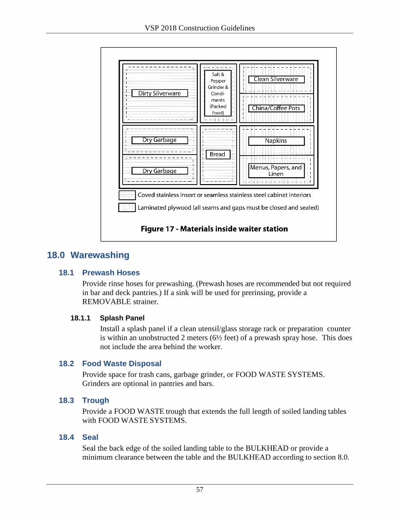
VSP 2018 Construction Guidelines
57
18.0 Warewashing
18.1 Prewash Hoses Provide rinse hoses for prewashing. (Prewash hoses are recommended but not required in bar and deck pantries.) If a sink will be used for prerinsing, provide a REMOVABLE strainer.
18.1.1 Splash Panel Install a splash panel if a clean utensil/glass storage rack or preparation counter is within an unobstructed 2 meters (6½ feet) of a prewash spray hose. This does not include the area behind the worker.
18.2 Food Waste Disposal Provide space for trash cans, garbage grinder, or FOOD WASTE SYSTEMS. Grinders are optional in pantries and bars.
18.3 Trough Provide a FOOD WASTE trough that extends the full length of soiled landing tables with FOOD WASTE SYSTEMS.
18.4 Seal Seal the back edge of the soiled landing table to the BULKHEAD or provide a minimum clearance between the table and the BULKHEAD according to section 8.0.

VSP 2018 Construction Guidelines
58
18.5 Design Design soiled landing tables to drain waste liquids and prevent contamination of adjacent clean surfaces.
18.6 Drain and Slope Provide across-the-counter gutters with drains and slope the clean landing tables to the gutters at the exit from the warewashing machines. If the first gutter does not effectively remove pooled water, install additional gutter(s) and drain line(s). Minimize the length of drain lines and, when possible, direct them in a straight line to the deck SCUPPER.
18.7 Space for Cleaning Provide sufficient space for cleaning around and behind equipment (e.g., FOOD WASTE SYSTEMS and warewashing machines). Refer to section 8.0 for spacing requirements.
18.8 Enclose Wiring Enclose FOOD WASTE SYSTEM wiring in a durable and easy to clean stainless steel or nonmetallic watertight conduit. Install all warewashing machine components at least 150 millimeters (6 inches) above the deck, except as noted in section 8.4.
18.9 Splash Panels Construct REMOVABLE splash panels of stainless steel to protect the FOOD WASTE SYSTEM and technical areas.
18.10 Materials Construct grinder cones, FOOD WASTE SYSTEM tables, and dish-landing tables from stainless steel with continuous welding. Construct platforms for supporting warewashing equipment from stainless steel.
18.11 Size Size warewashing machines for their intended use and install them according to the manufacturer’s recommendations.
18.12 Alarm Equip warewashing machines with an audible or visual alarm that indicates if the sanitizing temperature or chemical sanitizer drop below the levels stated on the machine data plate.
18.13 Data Plate Affix data plate so that the information is easy to read by the operator. The data plate must include the information in sections 18.13.1 through 18.13.4 as provided by the manufacturer of the warewash machine.
18.13.1 Water Temperatures Temperatures required for washing, rinsing (if applicable), and sanitizing.

VSP 2018 Construction Guidelines
59
18.13.2 Water Pressure Pressure required for the fresh water sanitizing rinse unless the machine is designed to use only a pumped sanitizing rinse.
18.13.3 Conveyer Speed or Cycle Time Conveyor speed in meters or feet per minute or minimum transit time for belt conveyor machines; minimum transit time for rack conveyor machines; or cycle time for stationary rack machines.
18.13.4 Chemical Concentration Chemical concentration (if chemical sanitizers are used).
18.14 Manuals and Schematics Provide warewash machine operating manuals and schematics of the internal BACKFLOW PREVENTION DEVICES.
18.15 Pot and Utensil Washing Provide pot and utensil washing facilities as listed in section 6.2.2.
18.16 Three-Compartment Sinks Correctly size three-compartment warewashing and potwashing sinks for their intended use. Use sinks that are large enough to submerge the largest piece of equipment used in the area that is served. Use sinks that have COVED, continuously welded, integral internal corners.
18.16.1 Prevent Excessive Contamination Install one of the following to prevent excessive contamination of rinse water with wash water splash:
• Gutter and drain: An across-the-counter gutter with a drain that divides the compartments. The gutter should extend the entire distance from the front edge of the counter to the backsplash.
• Splash shield: A splash shield at least 25 millimeters (1 inch) above the flood level rim of the sink between the compartments. The splash shield should extend the entire distance from the front edge of the counter to the backsplash;
• Overflow drain: An overflow drain in the wash compartment 100 millimeters (4 inches) below the flood level.
18.16.2 Hot Water Sanitizing Sinks Equip hot water sanitizing sinks with an easy-to-read TEMPERATURE- MEASURING DEVICE, a utensil/equipment retrieval system (e.g., long-handled stainless steel hook or other retrieval system), and a jacketed or coiled steam supply with a temperature control valve or electric heating system.

VSP 2018 Construction Guidelines
60
18.17 Shelving Provide sufficient shelving for storage of soiled and clean ware. Use open round tubular shelving or racks. Design overhead shelves to drain away from clean surfaces. Sufficient space must be determined by the initial sizing of the warewash area, as based on the profile or reference size from an existing vessel of the same cruise line per section 6.1.
18.18 Ventilation For ventilation requirements, see section 14.0.
19.0 Lighting This section applies to candy shops where consumers serve themselves from candy displays or dispensers and/or crew members serve candy to consumers and refill self-service containers.
19.1 Work Surface Provide a minimum of 220 lux (20 foot-candles) of light at the work surface level in all FOOD PREPARATION, FOOD SERVICE, and warewashing areas when all equipment is installed. Provide 220 lux (20 foot-candles) of lighting for equipment storage, garbage and FOOD lifts, garbage rooms, and toilet rooms, measured at 760 millimeters (30 inches) above the deck.
19.1.1 Behind and Around Equipment Provide a minimum light level of 110 lux (10 foot-candles) behind and around equipment as measured at the counter surface or at a distance of 760 millimeters (30 inches) above the deck (e.g., ice machines, combination ovens, beverage dispensers, etc.).
19.1.2 Countertops Provide a minimum light level of 220 lux (20 foot-candles) at countertops (e.g., beverage lines, etc.).
19.2 Deckhead-Mounted Fixtures For effective illumination, place the DECKHEAD-mounted light fixtures above the work surfaces and position them in an “L” pattern rather than a straight line pattern.
19.3 Installation Install light fixtures tightly against the BULKHEAD and DECKHEAD panels. Completely seal electrical penetrations to permit easy cleaning around the fixtures.
19.4 Light Shields Use shatter-resistant and REMOVABLE light shields for light fixtures. Completely enclose the entire light bulb or fluorescent light tube(s).
VSP 2018 Construction Guidelines
61
19.5 Provision Rooms Provide lighting levels of at least 220 lux (20 foot-candles) in provision rooms as measured at 760 millimeters (30 inches) above the deck while the rooms are empty. During normal operations when FOODS are stored in the rooms, provide lighting levels of at least 110 lux (10 foot-candles), measured at a distance of 760 millimeters (30 inches) above the deck.
19.6 Bars and Waiter Stations In bars and over dining room waiters’ stations designed for lowered lighting during normal operations, provide lighting that can be raised to 220 lux (20 foot-candles) during cleaning operations (as measured at 760 millimeters [30 inches] above the deck). Provide a minimum light level of 110 lux (10 foot-candles) at handwash stations at a bar, and ensure this level can be maintained at all times.
19.7 Light Bulbs Use shielded, coated, or otherwise shatter-resistant light bulbs in areas with exposed FOOD; clean equipment, utensils, and linens; or unwrapped single-service and single-use articles. This includes lights above waiter stations.
19.8 Heat Lamps Use shields that surround and extend beyond bulbs on infrared or other heat lamps to protect against breakage. Allow only the face of the bulb to be exposed.
19.9 Track or Recessed Lights Decorative track or recessed DECKHEAD-mounted lights above bar countertops, buffets, and other similar areas may be mounted on or recessed within the DECKHEAD panels without being shielded. But these fixtures must use specially coated, shatter-resistant bulbs.
20.0 Cleaning Materials, Filters, and Drinking Fountains
20.1 Facilities and Lockers for Cleaning Materials
20.1.1 Racks Provide BULKHEAD-mounted racks for brooms and mops or provide sufficient space and hanging brackets within CLEANING LOCKERS. Locate BULKHEAD-mounted racks outside of FOOD STORAGE, PREPARATION, or SERVICE areas. These racks may be located on the soiled side of warewash areas.
20.1.2 Stainless Steel Provide stainless steel vented lockers with COVED junctures for storing buckets, detergents, sanitizers, cloths, and other wet items.

VSP 2018 Construction Guidelines
62
20.1.3 Size and Location Size and locate cleaning lockers according to the needs of the vessel and make access convenient.
20.1.3.1 Multiple-Level Galleys If CLEANING LOCKERS are not provided in each of the preparation areas, provide a single CLEANING ROOM for each deck of multiple level galleys. Construct rooms used for cleaning materials in accordance with section 16.0.
20.1.4 Mop Cleaning Provide facilities equipped with a mop sink and ADEQUATE DECK DRAIN or a pressure washing system for cleaning mops and buckets and separate from FOOD facilities. The mop sink may be located on the soiled side of warewash areas.
20.1.5 Labeling Label all CLEANING LOCKERS and cleaning rooms with the exact wording “CLEANING MATERIALS ONLY.”
20.2 Filters
20.2.1 Potable Water Filters If used, install only point-of-use POTABLE WATER filters on ice machines, combination ovens, beverage machine, etc. Ensure filters are ACCESSIBLE for changing.
20.3 Drinking Fountains
20.3.1 Outlets Protected Ensure the water outlets from drinking fountains are slanted and protected by a sanitary guard.
20.3.2 Food Preparation Areas Provide drinking fountains with stainless steel cabinets and without filling spouts in FOOD PREPARATION AREAS.
20.3.3 Control Provide drinking fountains that allow control of the water stream.
20.3.4 Accessible Install drinking fountains that are ACCESSIBLE to galley personnel.

VSP 2018 Construction Guidelines
63
21.0 Waste Management
21.1 Food and Garbage Lifts
21.1.1 Interiors Provide FOOD and garbage lifts with interiors constructed of stainless steel that meet the same standards as section 16.0.
21.1.2 Decks Construct decks of a durable, nonabsorbent, NONCORRODING material with integral COVING.
21.1.3 Air Vents Position air vents in the upper portion of the BULKHEAD panels or in the DECKHEAD.
21.1.4 Drain Install a drain at the bottom of all lift shafts, including provision platform lifts and dumbwaiters. Install the drain flush with the floor of the shaft.
21.1.5 Dumbwaiter Interiors Construct the interiors of dumbwaiters of stainless steel with COVED junctures that meet the standards of section 16.0.
21.1.6 Lighting Provide light fixtures that are recessed or fitted with stainless steel guards.
21.1.7 Garbage Chutes If installed, construct garbage chutes of stainless steel and with COVED junctures. Install an automatic washing system for the garbage chute. Ensure the garbage chute meets all SOLAS and classification society requirements.
21.2 Trolley, Waste Container, and Cleaning Equipment Wash Rooms
21.2.1 Construction Construct BULKHEADS, DECKHEADS, and decks to the same standards as section 16.0.
21.2.2 Pressure-Washing System Provide a BULKHEAD-mounted pressure-washing system with a DECK SINK and drain. An enclosed automatic equipment washing machine or room may be used in place of the pressure washing system and DECK SINK.
21.2.3 Handwashing Station Provide an easily ACCESSIBLE handwashing station that meets the requirements of section 7.1.

VSP 2018 Construction Guidelines
64
21.2.4 Ventilation Provide ADEQUATE ventilation for the extraction of steam and heat.
21.3 Garbage Holding Facilities
21.3.1 Size and Location Construct the garbage and refuse storage or holding rooms of sufficient size to hold unprocessed waste for the longest expected time period between off loadings. Separate the refuse-storage room from all FOOD PREPARATION and storage areas.
21.3.2 Ventilation Provide ADEQUATE supply and exhaust ventilation to control odors, temperature, and humidity. Refer to section 33.0 for other requirements related to ventilation.
21.3.3 Refrigerated Storage Provide a sealed, refrigerated storage space for wet garbage that meets the requirements of section 15.0.
21.3.4 Handwashing Station Provide an easily ACCESSIBLE handwashing station that meets the requirements of section 7.1.
21.3.5 Drainage Provide ADEQUATE deck drainage to prevent pooling of any liquids.
21.3.6 Durable and Easily Cleanable Ensure all BULKHEADS and decks are durable and EASILY CLEANABLE.
21.4 Garbage Processing Areas
21.4.1 Size Appropriately size the garbage processing area for the operation and supply a sufficient number of sorting tables.
21.4.2 Sorting Tables Provide stainless steel sorting tables with COVED corners. Provide a table drain and direct it to a strainer-protected DECK DRAIN. If deck coaming is provided, ensure it is at least 80 millimeters (3 inches) in height and COVED on the inside and outside at the deck juncture.
21.4.3 Handwashing Station Provide a handwashing station that meets the requirements of section 7.1 and is ACCESSIBLE to both crew members working in the garbage room and to crew members dropping off garbage.

VSP 2018 Construction Guidelines
65
21.4.4 Cleaning Locker Provide a storage locker for cleaning materials that meets the requirements of section 20.1.
21.4.5 Bulkheads and Decks Ensure BULKHEADS and decks are durable, NONCORRODING, and EASILY CLEANABLE.
21.4.5.1 Deck Drains Provide DECK DRAINS to prevent liquids from pooling on the decks. Provide berm/coaming around all waste-processing equipment and ensure there is ADEQUATE deck drainage inside the berms.
21.4.6 Lighting Provide light levels of at least 220 lux (20 foot-candles) at the work surface levels and at the handwashing station.
21.4.7 Washing Containers Equip a sink with a pressure washer or an automatic washing machine for washing garbage/refuse handing equipment, garbage/refuse storage containers, and garbage barrels.
21.5 Black and Gray Water Systems
21.5.1 Drain Lines Limit installation of drain lines that carry BLACK WATER or other liquid waste directly overhead or horizontally through spaces used for FOOD AREAS. This includes areas for washing or storage of utensils and equipment, such as in bars and deck pantries and over buffet counters. Sleeve-weld or butt-weld steel pipe and heat fuse or chemically weld plastic pipe.
21.5.1.1 Piping Do not use push-fit or press-fit piping over these areas. For SCUPPER lines, factory assembled transition fittings for steel to plastic pipes are allowed when manufactured per ASTM F1973 or equivalent standard.
21.5.2 Drainage Systems Ensure BLACK and GRAY WATER drainage systems from cabins, FOOD AREAS, and public spaces are designed and installed to prevent waste back up and odor or gas emission into these areas.
21.5.3 Venting Vent BLACK WATER holding tanks to the outside of the vessel and ensure vented gases do not enter the vessel through any air intakes.

VSP 2018 Construction Guidelines
66
21.5.4 Independent Construct BLACK WATER holding tank vents so they are independent of all other tanks. Construct wastewater holding tank vents so they are independent of all sanitary water tanks. Wastewater tank vents can be combined with each other.
21.5.5 Reuse of Treated Black and Gray Water VSP will assess water reuse systems during plan reviews.
21.6 General Hygiene Construct handwashing stations in the following areas according to section 7.1.
21.6.1 Wastewater Areas Install at least one handwashing station in each main wastewater treatment, processing, and storage area.
21.6.2 Laundry Areas Install at least one handwashing station in soiled linen handling areas and at the main exits of the main laundry. Vessel owners will provide locations during the plan review.
21.6.3 Housekeeping Areas Install handwashing stations in housekeeping areas as described in section 35.1. Provide each handwashing station with a soap dispenser, paper towel dispenser, waste receptacle, and sign that states “wash hands often,” “wash hands frequently,” or similar wording in English and in other languages, where appropriate.
22.0 Potable Water System
22.1 Striping
22.1.1 Potable Water Lines Stripe or paint POTABLE WATER lines either in accordance with ISO 14726 (blue/green/blue) or in blue only.
22.1.2 Distillate and Permeate Water Lines Stripe or paint DISTILLATE and PERMEATE WATER LINES directed to the POTABLE WATER system in accordance with ISO 14726 (blue/gray/blue).
22.1.3 Other Piping No other lines should have the color designations listed in 22.1.1 or 22.1.2.
VSP 2018 Construction Guidelines
67
22.1.4 Intervals Paint or stripe these lines at 5-meter (15-foot) intervals and on each side of partitions, decks, and BULKHEADS except where decor would be marred by such markings. This includes POTABLE WATER supply lines in technical lockers.
22.1.5 Downstream of an RP Assembly Lines downstream of an RP ASSEMBLY must not be striped as POTABLE WATER.
22.1.6 Refrigerant Brine Lines and Chilled Water Lines Identify refrigerant brine lines and chilled water lines in all FOOD AREAS with either ISO 14726 (blue/white/blue) or by another uniquely identifiable method to prevent CROSS-CONNECTIONS.
22.2 Bunker Stations
22.2.1 Position Connections Position the filling line hose connections at least 450 millimeters (18 inches) above the deck; paint or stripe the filling lines either in blue only or in accordance with ISO 14726.
22.2.2 Connection Caps Equip filling line hose connections with tight-fitting caps fastened by a NONCORRODING chain so the cap does not touch the deck when hanging.
22.2.3 Unique Connections Use unique connections that only fit POTABLE WATER hoses.
22.2.4 Labeling Label the filling lines with the exact wording “POTABLE WATER FILLING” with lettering at least 13 millimeters (1/2 inch) high and stamped, stenciled, or painted on the filling lines or on the BULKHEAD at the filling line.
22.2.5 Filter Location If any filters are used in the bunkering process, locate them ahead of the HALOGENATION injection point. Ensure any filters used in the bunkering process are easily ACCESSIBLE and can be removed for inspection and cleaning.
22.3 Filling Hoses
22.3.1 Approved Provide hoses APPROVED for POTABLE WATER. Hoses must be SMOOTH and durable and have an impervious lining, caps on each end, and fittings unique to the POTABLE WATER connections.

VSP 2018 Construction Guidelines
68
22.3.2 At Least Two Hoses Provide at least two 15-meter (50-foot) hoses per bunker station.
22.3.3 Label Hoses Label POTABLE WATER hoses with the exact wording “POTABLE WATER ONLY” with lettering at least 13 millimeters (1/2 inch) high and stamped, stenciled, or painted at each connection end.
22.4 Potable Water Hose Storage
22.4.1 Construction Construct POTABLE WATER hose lockers from SMOOTH, nontoxic, NONCORRODING, and EASILY CLEANABLE materials.
22.4.2 Mounting Mount POTABLE WATER hose lockers at least 450 millimeters (18 inches) above the deck.
22.4.3 Self-Draining Design POTABLE WATER hose lockers to be self-draining.
22.4.4 Label Lockers Label POTABLE WATER hose lockers with the exact wording “POTABLE WATER HOSE AND FITTING STORAGE” in letters at least 13 millimeters (1/2 inch) high.
22.4.5 Size Provide storage space for at least four 15-meter (50-foot) POTABLE WATER bunker hoses per bunker station.
22.5 International Fire Shore Connections and Fire Sprinkler Shore Connections
22.5.1 RP Assembly Install an RP ASSEMBLY at all connections where hoses from shore-side POTABLE WATER supplies will be connected to nonpotable systems onboard the vessel.
22.6 Storage and Production Capacity for Potable Water
22.6.1 Minimum Storage Capacity Provide a minimum of 2 days storage capacity that assumes 120 liters (30 gallons) of water per day per person for the maximum capacity of crew and passengers on the vessel.

VSP 2018 Construction Guidelines
69
22.6.2 Production Capacity Provide POTABLE WATER production capacity of 120 liters (30 gallons) per day per person for the maximum capacity of crew and passengers on the vessel.
22.7 Potable Water Storage Tanks
22.7.1 General Requirements
22.7.1.1 Independent of Vessel Shell Ensure POTABLE WATER storage tanks are independent of the shell of the vessel.
22.7.1.2 No Common Wall Ensure POTABLE WATER storage tanks do not share a common wall with other tanks containing nonpotable water or other liquids.
22.7.1.3 Cofferdam Provide a 450-millimeter (18-inch) cofferdam above and between POTABLE WATER TANKS and tanks that are not for storage of POTABLE WATER and between POTABLE WATER TANKS and the shell. Skin or double-bottom tanks are not allowed for POTABLE WATER storage.
22.7.1.4 Deck Top If the deck is the top of POTABLE WATER TANKS, these tanks must be identified during the plan review. The shipyard will provide to owners a written declaration of the tanks involved and drawings of the areas that include these tanks.
22.7.1.5 Tanks with Nonpotable Liquid Do not install tanks containing nonpotable liquid directly over POTABLE WATER TANKS.
22.7.1.6 Coatings Use APPROVED POTABLE WATER TANK coatings. Follow all of the manufacturer’s recommendations for applying, drying, and curing tank coatings. Provide the following for tank coatings:
• Written documentation of approval from the certification organization (independent of the coating manufacturer).
• Manufacturer’s recommendations for applying, drying, and curing.

VSP 2018 Construction Guidelines
70
• Written documentation that the manufacturer’s recommendations have been followed for applying, drying, and curing.
22.7.1.7 Items That Penetrate Tank Coat all items that penetrate the tank (e.g., bolts, pipes, pipe flanges) with the same product used for the tank’s interior.
22.7.1.8 Superchlorination Design tanks to be superchlorinated one tank at a time.
22.7.1.9 Lines for Nonpotable Liquids Ensure that lines for nonpotable liquids do not pass through POTABLE WATER TANKS.
22.7.1.10 Nonpotable Lines Above Potable Water Tanks Minimize the use of nonpotable lines above POTABLE WATER TANKS. If nonpotable water lines are installed, do not use mechanical couplings or push-fit or press-fit piping on lines above tanks. For SCUPPER lines, factory assembled transition fittings for steel to plastic pipes are allowed when manufactured per ASTM F1973 or equivalent standard.
22.7.1.11 Coaming If coaming is present along the edges or top of the tank, provide slots along the coaming to allow leaking liquids to run off and be detected.
22.7.1.12 Welded Pipes Treat welded pipes over POTABLE WATER storage tanks to make them corrosion resistant.
22.7.1.13 Lines Inside Potable Water Tanks Treat all POTABLE WATER lines inside POTABLE WATER TANKS to make them jointless and NONCORRODING.
22.7.1.14 Label Tanks Label each POTABLE WATER TANK on its side and where clearly visible with a number and the exact wording “POTABLE WATER” in letters a minimum of 13 millimeters (1/2 inch) high.
22.7.1.15 Sample Cock Install at least one sample cock at least 450 millimeters (18 inches) above the deck plating on each tank. The sample cock must be easily ACCESSIBLE.

VSP 2018 Construction Guidelines
71
Point sample cocks down and identify them with the appropriate tank number.
22.7.2 Storage Tank Access Hatch
22.7.2.1 Installation Install an access hatch for entry on the sides of POTABLE WATER TANKS.
22.7.3 Storage Tank Water Level
22.7.3.1 Automatic Provide an automatic method for determining the water level of POTABLE WATER TANKS. Visual sight glasses are acceptable.
22.7.4 Storage Tank Vents
22.7.4.1 Location Ensure that air-relief vents end at least 1,000 millimeters (40 inches) above the maximum load level of the vessel. Make the cross-sectional area of vents equal to or greater than that of the tank filling line. Position the end of the vents so openings face down or are otherwise protected, and install a 16-mesh corrosion-resistant screen.
22.7.4.2 Single Pipe A single pipe may be used as a combination vent and overflow.
22.7.4.3 Vent Connections Do not connect the vent of a POTABLE WATER TANK to the vent of a tank that is not a POTABLE WATER TANK.
22.7.5 Storage Tank Drains
22.7.5.1 Design Design tanks to drain completely.
22.7.5.2 Drain Opening Provide a drain opening at least 100 millimeters (4 inches) in diameter that preferably matches the diameter of the inlet pipe.
22.7.5.3 Suction Pump If drained by a suction pump, provide a sump and install the pump suction port in the bottom of the sump.

VSP 2018 Construction Guidelines
72
Install separate pumps and piping not connected to the POTABLE WATER distribution system for draining tanks (Figure 18).
22.8 Suction Lines Place suction lines at least 150 millimeters (6 inches) from the tank bottom or sump bottom.
22.9 Potable Water Distribution System
22.9.1 Location Locate DISTILLATE, PERMEATE, and distribution lines at least 450 millimeters (18 inches) above the deck plating or the normal bilge water level. Avoid BLIND LINES in the POTABLE WATER distribution system.

VSP 2018 Construction Guidelines
73
22.9.2 Pipe Materials Do not use lead, cadmium, or other hazardous materials for pipes, fittings, or solder.
22.9.3 Fixtures That Require Potable Water Supply only POTABLE WATER to the following areas and plumbing connections, regardless of the locations of these fixtures on the vessel:
• All showers and sinks (not just in cabins). • Chemical feed tanks for the POTABLE WATER system or
RECREATIONAL WATER systems. • Drinking fountains. • Emergency showers. • Eye wash stations. • FOOD AREAS. • Handwash sinks. • HVAC fan rooms. • Medical facilities. • Deck and window cleaning facilities.
UTILITY SINKS for engine/mechanical spaces are excluded.
22.9.4 Paint or Stripe Paint or stripe POTABLE WATER piping and fittings either in blue only or in accordance with ISO 14726 at 5-meter (15-foot) intervals and on each side of partitions, decks, and BULKHEADS except where the decor would be marred by such markings. This includes POTABLE WATER supply lines in technical lockers.
22.9.5 Steam Generation for Food Areas Use POTABLE WATER to generate steam applied directly to FOOD and FOOD-CONTACT SURFACES. Generate the steam locally from FOOD SERVICE equipment designed for this purpose (e.g., vegetable steamers, combination ovens, etc.).
22.9.5.1 Nonpotable Water Steam generated by nonpotable water may be applied indirectly to FOOD or FOOD equipment if routed through coils, tubes, or separate chambers.
22.10 Disinfection of the Potable Water System
22.10.1 Before Placed in Service Clean, disinfect, and flush POTABLE WATER TANKS and all parts of the POTABLE WATER system before the system is placed in service.
VSP 2018 Construction Guidelines
74
22.10.2 Free Chlorine Solution Ensure DISINFECTION is accomplished using a 50-MG/L (50-ppm) free chlorine solution for a minimum of 4 hours. Use only POTABLE WATER for these procedures. Prior VSP agreement is required for use of alternative APPROVED DISINFECTION practices.
22.10.3 Documentation Provide written documentation showing that representative sampling was conducted at PLUMBING FIXTURES on each deck throughout the vessel (forward, aft, port, and starboard) to ensure the 50-MG/L (ppm) free chlorine residual circulated throughout the distribution system including distant sampling point(s).
22.11 Potable Water Pressure Tanks
22.11.1 No Connection to Nonpotable Water Tanks Do not connect POTABLE WATER hydrophore tanks to nonpotable water tanks through the main air compressor.
22.11.2 Filtered Air Supply Provide a filtered air supply from a dedicated compressor or through a nonpermanent quick disconnect for a PORTABLE compressor. The compressor must not emit oil into the final air product.
22.12 Potable Water Pumps
22.12.1 Sizing Size POTABLE WATER pumps to meet the vessel’s maximum capacity service demands. Do not use POTABLE WATER pumps for any other purpose.
22.12.2 Priming Use nonpriming POTABLE WATER pumps or POTABLE WATER pumps that prime automatically. Use a direct connection when supplying priming water to a POTABLE WATER pump.
22.12.3 Pressure Properly size POTABLE WATER pumps and distribution lines so pressure is maintained at all times and at levels to properly operate all equipment.
22.13 Evaporators and Reverse Osmosis Plants
22.13.1 Location of Seawater Inlets Locate SANITARY SEAWATER intakes (sea chests) forward of all overboard waste discharge outlets such as emergency and routine discharge lines from waste water treatment facilities, the bilge, RECREATIONAL WATER FACILITIES, and ballast tanks.

VSP 2018 Construction Guidelines
75
This does not include the following: • Discharges from DECK DRAINS on open decks. • Cooling lines with no chemical treatment. • Alarmed vent/overflow pipes for GRAY WATER, treated GRAY or
BLACK WATER, and ballast tank with an automatic shutoff system for SANITARY SEAWATER intake. These alarms must be visual and audible and must sound in a space that is continuously occupied.
• Alarmed emergency bilge discharge lines with an automatic shutoff system for SANITARY SEAWATER intake. These alarms must be visual and audible and must sound in a space that is continuously occupied. GRAY and BLACK WATER cannot be able to be transferred to the bilge with this type of design.
• Alarmed emergency ballast discharge line with an automatic shutoff system for SANITARY SEAWATER intake. These alarms must be visual and audible and must sound in a space that is continuously occupied.
• Discharges from the anchor chain locker are allowed forward of the sea chest if the chain is rinsed/cleaned only with sea water.
• Alarmed vent/overflow pipes for heeling tanks and laundry water storage tanks with an automatic shutoff system for SANITARY SEAWATER intake are allowed. These alarms must be visual and audible and must sound in a space that is continuously occupied.
22.13.2 Direct Connections Use only direct connections from the evaporators and reverse osmosis plants to the POTABLE WATER system.
22.13.3 Potable and Nonpotable Water Systems If an evaporator or reverse osmosis plant makes water for both the POTABLE WATER system and a nonpotable water system, install an AIR GAP or RP ASSEMBLY on the line supplying the nonpotable water system. Onboard water sources such as TECHNICAL WATER, air conditioning condensate, or wastewater of any kind (treated or untreated) are not allowed for POTABLE WATER production.
22.13.4 Instructions Post narrative, step-by-step operating instructions for manually operated evaporators and for any reverse osmosis plants near the units.
22.13.5 Discharge to Waste Ensure water production units connected to the POTABLE WATER system have the ability to discharge to waste if the distillate is not fit for use.

VSP 2018 Construction Guidelines
76
22.13.6 Indicator and Alarm Install a low-range salinity indicator, operating temperature indicator, automatic discharge to waste system, and alarm with trip setting on water production equipment.
22.13.7 High-Saline Discharge If routed for discharge, direct high-saline discharge from evaporators to the bilge or overboard through an AIR GAP or RP ASSEMBLY.
22.14 Halogenation Locate storage areas of salt used to generate chlorine for potable water close to the chlorine production plant. Construct storage areas to dry food storage standards.
22.14.1 Bunkering and Production
22.14.1.1 Backflow Prevention Provide POTABLE WATER taps with appropriate BACKFLOW prevention at the HALOGEN supply tanks.
22.14.1.2 Halogen Injection Control HALOGEN injection by a flow meter or an analyzer with a sample point located at least 3 meters (10 feet) downstream of the HALOGEN injection point. Installed analyzers must have a sample point to calibrate the analyzer. A static mixer may be used to reduce the distance between the HALOGEN injection point and the sample cock or HALOGEN analyzer sample point. Ensure that the mixer is installed per the manufacturer’s recommendation. Provide all manufacturers’ literature for installation, operation, and maintenance.
22.14.1.3 pH Adjustment Provide automatic PH adjustment equipment for water bunkering and production. Install analyzer, controller, and dosing pumps that are designed to accommodate changes in flow rates.
22.14.2 Distribution
22.14.2.1 Sample Point Provide an analyzer controlled, automatic HALOGENATION system. Install the analyzer probe sample point at least 3 meters (10 feet) downstream of the HALOGEN injection point. The analyzer must have a sample point for calibration. A static mixer may be used to reduce the distance between the HALOGEN injection point and the HALOGEN analyzer sample point. Ensure the static mixer is installed per the manufacturer’s
VSP 2018 Construction Guidelines
77
recommendation. Provide all manufacturers’ literature for installation, operation, and maintenance.
22.14.2.2 Free Halogen Probes Use probes to measure free HALOGEN and link them to the analyzer/controller and chemical dosing pumps.
22.14.2.3 Backup Halogenation Pump Provide a back-up HALOGENATION pump with an automatic switchover that begins pumping HALOGEN when the primary (in-use) pump fails or cannot meet the HALOGENATION demand.
22.14.2.4 Chemical Injection Dosing Point A check valve or nonreturn valve must be installed between the distribution halogen and pH pumps and the injection points. In addition,
• The potable water distribution halogenation and pH chemical injection dosing points must be located on the delivery line downstream of the potable water pumps, OR
• If the injection dosing point is before the potable water pumps, it must be located above the chemical dosing tanks.
22.14.2.5 Probe/Sample Location Locate the HALOGEN analyzer probe at a distant point in each distribution system loop where significant water flow exists.
22.14.2.6 Alarm Provide an audible alarm in a continually occupied watch station (e.g., the engine control room or bridge) to indicate low or high free HALOGEN readings at each distant point analyzer.
22.14.2.7 Backflow Prevention Provide POTABLE WATER taps with appropriate BACKFLOW prevention at HALOGEN supply tanks.
22.14.2.8 Free Halogen Analyzer-Chart Recorder Provide continuous recording free HALOGEN analyzer-chart recorder(s) that have ranges of 0.0 to 5.0 MG/L (ppm) and indicate the level of free HALOGEN for 24-hour time periods (e.g., circular 24-hour charts). Electronic data loggers with CERTIFIED DATA SECURITY FEATURES may be installed in lieu of chart recorders. Acceptable data loggers produce records that conform to the principles of operation and data display required of the analog charts, including printing the records. Use electronic data loggers that log times in increments of

VSP 2018 Construction Guidelines
78
<15 minutes. Written documentation from the data logger manufacturer, such as a letter or instruction manual, must be provided to verify that the features are secure.
22.14.2.9 Multiple Distribution Loops When supplying POTABLE WATER throughout the distribution network with more than one ring or loop (lower to upper decks or forward to aft), there must be
• Pipe connections that link those loops and a single distant point monitoring analyzer or
•
Individual analyzers on each ring or loop.
A single return line that connects to only one ring or loop of a multiple loop system is not acceptable. One chart recorder may be used to record multiple loop readings. POTABLE WATER distribution loops/rings supplied by separate HALOGEN dosing equipment must include an analyzer chart recorder at a distant point for each loop/ring.
23.0 Cross-Connection Control
23.1 Backflow Prevention Use appropriate BACKFLOW prevention at all CROSS-CONNECTIONS. This may include nonmechanical protection such as an AIR GAP or a mechanical BACKFLOW PREVENTION DEVICE. Install BACKFLOW PREVENTION DEVICES and AIR GAPS to be ACCESSIBLE for inspection, testing, service and maintenance. If access panels are required, provide panels large enough for testing, service and maintenance.
23.2 Air Gaps AIR GAPS should be used where feasible and when water under pressure is not required.
23.3 Atmospheric Vent A mechanical BACKFLOW PREVENTION DEVICE must have an atmospheric vent. Provide an AIR GAP for the atmospheric vent.
23.4 Protect Against Health Hazards Ensure that connections where there is a potential of a HEALTH HAZARD are protected by AIR GAPS or BACKFLOW PREVENTION DEVICES designed to protect against HEALTH HAZARDS.

VSP 2018 Construction Guidelines
79
23.5 Test Kit Provide an appropriate test kit for all testable devices. Test all testable devices after installation and provide pressure differential test results for each device.
23.6 Atmospheric Vacuum Breaker When used, install an ATMOSPHERIC VACUUM BREAKER (AVB) 150 millimeters (6 inches) above the fixture flood level rim with no valves downstream of the device.
23.7 Atmospheric or Hose Bib Vacuum Breaker Ensure an AVB or HOSE-BIB CONNECTED VACUUM BREAKER (HVB) is not installed at a connection where it can be subjected to CONTINUOUS PRESSURE for more than 12 continuous hours.
23.8 Connections Between Potable and Black Water Systems Ensure any connection between the POTABLE WATER system and the BLACK WATER system is through an AIR GAP. Where feasible, water required for the BLACK WATER system should not be from the POTABLE WATER system.
23.9 Protection Against Backflow Protect the following connections to the POTABLE WATER system against BACKFLOW (BACKSIPHONAGE or BACKPRESSURE) with AIR GAPS or mechanical BACKFLOW PREVENTION DEVICES:
• Air conditioning expansion tanks. • Automatic galley hood washing systems. • Beauty and barber shop spray-rinse hoses. • BLACK WATER or combined GRAY WATER/BLACK WATER systems.
An AIR GAP is the only allowable protection for these connections. • Boiler feed water tanks. • Cabin shower hoses, toilets, WHIRLPOOL SPA tubs, and similar facilities. • Chemical tanks. • Decorative water features and fountains. • Detergent and chemical dispensers. • Fire system. • FOOD SERVICE equipment such as coffee machines, ice machines, juice
dispensers, combination ovens, and similar equipment. • Freshwater or saltwater ballast systems. • Garbage grinders and FOOD WASTE SYSTEMS. • High saline discharge line from evaporators. An AIR GAP or an RP
ASSEMBLY is the only allowable protection for these lines. • Hose-bib connections. • Hospital and laundry equipment.

VSP 2018 Construction Guidelines
80
• International fire and fire sprinkler water connections. An RP ASSEMBLY is the only allowable device for this connection.
• Mechanical warewashing machines. • Photographic laboratory developing machines and UTILITY SINKS. • POTABLE WATER, bilge, and sanitary pumps that require priming. • POTABLE WATER supply to automatic window washing systems that can be
used with chemicals or chemical mix tanks. • RECREATIONAL WATER FACILITIES. • Spa steam generators where essential oils can be added. • Toilets, urinals, and shower hoses. • Water softener and mineralizer drain lines including backwash drain lines. An
AG or RP are the only allowable protections for these lines. • Water softeners for nonpotable fresh water. • Any other connection between the POTABLE WATER system and a
nonpotable water system such as the GRAY WATER, laundry, or TECHNICAL WATER system. An AIR GAP or an RP ASSEMBLY is the only allowable protection for these connections.
• Hi-Fog or similar suppression systems connected to POTABLE WATER TANKS
• Any other connection to the POTABLE WATER system where contamination or BACKFLOW can occur.
23.10 Seawater Lines and Potable Water Do not make any connections to the SANITARY SEAWATER LINES between the POTABLE WATER production plant supply pump and the POTABLE WATER production plant.
23.11 Seawater Lines and Recreational Water Facilities Do not make any connections to the SANITARY SEAWATER LINES between the RECREATIONAL WATER FACILITY supply pump and the RECREATIONAL WATER FACILITIES.
23.12 Distillate and Permeate Water Lines Provide an AIR GAP or BACKFLOW PREVENTION DEVICE at connections to the DISTILLATE and PERMEATE WATER LINES intended for the POTABLE WATER system.
23.13 Sanitary Seawater Lines Provide an AIR GAP or BACKFLOW PREVENTION DEVICE for connections to the SANITARY SEAWATER LINES.
23.14 List of Connections to Potable Water System Develop and provide a list of all connections to the POTABLE WATER system where there is a potential for contamination with a pollutant or contaminant. At a minimum, this list must include the following:
VSP 2018 Construction Guidelines
81
• Exact location of the connection. • PLUMBING FIXTURE (plumbing part [pipe, valve, etc.]) or component
connected (what the fixture is connected to [sprinkler, shower, tank, etc.]). • Form of protection used:
o AIR GAPS or o Manufacturer name and device number (if a device is used).
• A testing record for each device with test cocks. Repeat connections such as toilets and showers can be grouped together under a single entry, as appropriate, with the total number of connections listed.
24.0 Heat Exchangers Used for Cooling or Heating Sanitary Seawater and Potable Water
24.1 Fabrication Fabricate heat exchangers that use, cool, or heat SANITARY SEAWATER or POTABLE WATER so a single failure of any barrier will not cause a CROSS-CONNECTION or permit BACKSIPHONAGE of contaminants into the POTABLE WATER system.
24.2 Design Where both SANITARY SEAWATER or POTABLE WATER and any nonpotable liquid are used, design heat exchangers to protect the SANITARY SEAWATER or POTABLE WATER from contamination by one of the designs in sections 24.2.1 or 24.2.2.
24.2.1 Double-Wall Construction Double-wall construction between the SANITARY SEAWATER or POTABLE and nonpotable liquids with both of the following safety features:
• A void space to allow any leaking liquid to drain away. • An alarm system to indicate a leak in the double wall.
24.2.2 Single-Wall Construction Single-wall construction with all of the safety features in sections 24.2.2.1 through 24.2.2.3.
24.2.2.1 Higher Pressure Higher pressure of at least 1 bar on the SANITARY SEAWATER or POTABLE WATER side of the heat exchanger.
24.2.2.2 Automatic Valve An automatic valve arrangement that closes SANITARY SEAWATER or POTABLE WATER circulation in the heat exchanger when the pressure difference is less than 1 bar.

VSP 2018 Construction Guidelines
82
24.2.2.3 Alarm An alarm system that sounds when the diverter valve directs SANITARY SEAWATER or POTABLE WATER from the heat exchanger.
25.0 Recreational Water Facilities Water Source
25.1 Filling System Provide a filling system that allows for the filling of each RECREATIONAL WATER FACILITY with SANITARY SEAWATER or POTABLE WATER. For a compensation or make-up tank supplied with POTABLE water, an overflow line located below the fill line and at least twice the diameter of the fill line is an acceptable method of BACKFLOW protection as long as the overflow line discharges to the wastewater system through an indirect connection. If make-up water is introduced into the RECREATIONAL WATER FACILITY directly, the water should be at the same level of HALOGENATION and PH as the RWF before entering the RECREATIONAL WATER FACILITY. Avoid BLIND LINES in the water systems of recreational water facilities.
25.2 Compensation or Make-Up Tank Where make-up water is required to replace water loss due to splashing, carry out, and other volume loss, install an appropriately designed compensation or make-up tank to ensure that ADEQUATE chemical balance can be maintained.
25.3 Combining Recreational Water Facilities No more than two similar RECREATIONAL WATER FACILITIES may be combined. CHILDREN’S POOLS and BABY-ONLY WATER FACILITIES must not be combined with any other type of RWFs.
25.4 Independent Manual Testing When combining RECREATIONAL WATER FACILITIES, provisions must be made for independent manual water testing within the mechanical room for each RECREATIONAL WATER FACILITY.
25.5 Independent Slide Recreational Water Facility and Adult Swimming Pool An independent slide RECREATIONAL WATER FACILITY and an adult SWIMMING POOL may be combined provided that the water volume added to the slide and the slide pump capacity are sufficient to maintain the TURNOVER rate as shown in section 29.10. Any other combinations of RECREATIONAL WATER FACILITIES will be decided on a case-by-case basis during the plan review.

VSP 2018 Construction Guidelines
83
26.0 Recreational Water Facility Showers and Toilet Facilities
26.1 Shower Temperature Equip showers to provide POTABLE WATER at a temperature not to exceed 43°C (110°F) during normal operations.
26.2 Shower Location Install showers within 10 meters (33 feet) of every entry point to each RECREATIONAL WATER FACILITY. For beach entry RECREATIONAL WATER FACILITIES, install a minimum of one showerhead per 10 meters (33 feet) of perimeter within 10 meters (33 feet) of the beach perimeter. Install a minimum of one shower at each waterslide staircase entrance. The location and number of showers for facilities with multiple entrances will be determined during the plan review.
26.3 Showers for Children RECREATIONAL WATER FACILITIES designed for use by children under 6 years of age must have appropriately sized shower facilities. Standard height is acceptable, but the mechanism to operate the flow of water must not be more than 1 meter (3 feet) above the deck.
26.4 Showers Drainage Shower floors must be sloped to drain. Shower water must discharge to waste, and not into the RECREATIONAL WATER FACILITY.
26.5 Toilet Facilities Locate toilet facilities within one fire zone (approximately 48 meters [157 feet]) of each RECREATIONAL WATER FACILITY and on the same deck or adjacent decks if there is no obstruction between the RECREATIONAL WATER FACILITY area and entrances to the toilets. If toilets are not located on the same deck as the RECREATIONAL WATER FACILITY, they should be easily visible and ACCESSIBLE from the RECREATIONAL WATER FACILITY area. Install a minimum of two separate toilet rooms (either two unisex or one male and one female). Each toilet facility must include a toilet and a handwashing facility. The total number of toilets and toilet facilities required will be assessed during the plan review. Urinals may be installed in addition to the required toilet, but may not replace the toilet.
26.6 Waterslide Toilets and Showers Toilet facilities for a waterslide may be located on the same deck within one fire zone (approximately 48 meters [157 feet]) as the staircase entrance as long as this is the only access to the waterslide.

VSP 2018 Construction Guidelines
84
Showers for a waterslide may be located within 10 meters (33 feet) of the staircase entrance as long as this is the only access to the waterslide.
26.7 Diaper-Changing Facilities Provide diaper-changing facilities within one fire zone (approximately 48 meters [157 feet]) and on the same deck of any BABY-ONLY WATER FACILITY. If these facilities are placed within toilet rooms, there must be one facility located within each toilet room (men’s, women’s, and unisex). Diaper-changing facilities must be equipped in accordance with section 34.2.1.
27.0 Recreational Water Facility Drainage
27.1 Independent System Provide an independent drainage system for RECREATIONAL WATER FACILITIES from other drainage systems. If RECREATIONAL WATER FACILITY drains are connected to another drainage system, provide an AIR GAP or a DUAL SWING CHECK VALVE between the two. This includes the drainage for compensation or make-up tanks.
27.2 Slope Slope the bottom of the RECREATIONAL WATER FACILITY toward the drains to achieve complete drainage.
27.3 Seating Drains If seating is provided inside a RECREATIONAL WATER FACILITY, ensure drains are installed to allow for complete draining of the seating area (including seats inside WHIRLPOOL SPAS and SPA POOLS).
27.4 Drain Completely Decorative and working features of a RECREATIONAL WATER FACILITY must be designed to drain completely and must be constructed of nonporous EASILY CLEANABLE materials. These features must be designed to be shock HALOGENATED.
28.0 Recreational Water Facility Safety
28.1 Antientrapment Drain Covers and Suction Fittings Where referenced within these guidelines, drain covers must comply with the requirements in ASME A112.19.8-2007, including addenda. See table below for primary and secondary ANTIENTRAPMENT requirements. VSP is aware that the requirements shown in Table 28.1.7 may not fully meet the letter of the Virginia Graeme Baker Act, but we also recognize the life-safety concerns for rapid dumping of RECREATIONAL WATER FACILITIES in conditions of instability at sea. Therefore, it is the owner’s decision to meet or exceed VSP requirements.

VSP 2018 Construction Guidelines
85
28.1.1 Installation Install dual drains at least 1 meter (3 feet) apart and at the lowest point in the RECREATIONAL WATER FACILITY. Ensure that there are no intermediate drain isolation valves on the lines between the drains (Figure 19a). In a channel system (an UNBLOCKABLE DRAIN), a grate-type cover would be attached to the channel (Figure 19b).
28.1.2 ASME A112.19.8M-2007 When fully assembled and installed, SUCTION FITTINGS must prevent the potential for body, digit, or limb entrapment in accordance with ASME A112.19.8M-2007.
28.1.3 Stamped and Certified Manufactured drain covers and SUCTION FITTINGS must be stamped and certified in accordance with the standards set forth in ASME A112.19.8-2007.
28.1.4 Design of Field Fabricated Covers and Fittings The design of custom/shipyard constructed (field fabricated) drain covers and SUCTION FITTINGS must be fully specified by a registered design professional in accordance with ASME A112.19.8-2007. The specifications must fully address cover/grate loadings; durability; hair, finger, and limb

VSP 2018 Construction Guidelines
86
entrapment issues; cover/grate secondary layer of protection; related sump design; and features specific to the RECREATIONAL WATER FACILITY.
28.1.5 Alternate to Marking Field Fabricated Fittings As an alternate to marking custom/shipyard constructed (field fabricated) drain cover fittings, the owner of the facility where these fittings will be installed must be advised in writing by the registered design professional of the information set forth in section 7.1.1 of ASME A112.19.8-2007.
28.1.6 Accompanying Letter A letter from the shipyard must accompany each custom/shipyard constructed (field fabricated) drain cover fitting. At a minimum, the letter must specify the shipyard, name of the vessel, specifications and dimensions of the drain cover, as noted above, and the exact location of the RECREATIONAL WATER FACILITY for which it was designed. The registered design professional’s name, contact information, and signature must be on the letter.
28.1.7 Antientrapment/Antientanglement Requirements See Table 28.1.7 for ANTIENTRAPMENT and ANTIENTANGLEMENT requirements for drains and SUCTION FITTINGS in RECREATIONAL WATER FACILITIES.
Table 28.1.7 ANTIENTRAPMENT Requirements for RECREATIONAL WATER FACILITIES (Does not include facilities designed with zero depth and drains not under direct suction)
Option* Type Drainage/Recirculation System Cover Design
Secondary ANTI-ENTRAPMENT
1 GRAVITY only
Multiple drains (2 or more drains greater than 1 meter [3 feet] apart)
Standard design compliant with A112.19.8)
(not ASME
Alarm
2 GRAVITY only
Multiple drains (2 or more drains greater than 1 meter [3 feet] apart)
ASME A112.19.8 compliant cover
None
3 GRAVITY only
Single UNBLOCKABLE DRAIN (per ASME A112.19.8)
Standard design compliant with
(not ASME
Alarm
4 GRAVITY only
Single UNBLOCKABLE DRAIN (per ASME A112.19.8)
ASME A112.19.8 compliant cover
None
5 GRAVITY only
Single BLOCKABLE DRAIN or multiple drains (less than 1 meter [3 feet] apart)
ASME A112.19.8 compliant cover
GDS
6 SUCTION FITTING
Multiple drains (2 or more drains per pump with drains greater than 1 meter [3 feet] apart)
ASME A112.19.8 compliant cover
None
7 SUCTION FITTING
Single UNBLOCKABLE DRAIN (per ASME A112.19.8-2007)
ASME A112.19.8 compliant cover
SVRS or APS
VSP 2018 Construction Guidelines
87
Option* Type Drainage/Recirculation System Cover Design
Secondary ANTI-ENTRAPMENT
8 SUCTION FITTING
Single BLOCKABLE DRAIN or multiple drains (less than 1 meter [3 feet] apart)
ASME A112.19.8 compliant cover
SVRS or APS
*Options 1 through 5 are for fittings not under direct suction. These include both fittings to drain the RECREATIONAL WATER FACILITY and fittings used to recirculate the water. Options 6 through 8 are for fittings under direct suction. These include fittings to drain the RECREATIONAL WATER FACILITY and fittings to recirculate the water. **Definitions:
• Alarm = the audible alarm must sound in a continuously manned space AND at the RECREATIONAL WATER FACILITY. This alarm is for all draining: accidental, routine, and emergency.
• GDS (GRAVITY DRAINAGE SYSTEM) = a drainage system that uses a collector tank from which the pump draws water. Water moves from the RECREATIONAL WATER FACILITY to the collector tank due to atmospheric pressure, gravity, and the displacement of water by bathers. There is no direct suction at the RECREATIONAL WATER FACILITY.
• SVRS (SAFETY VACUUM RELEASE SYSTEM) = a system that stops pump operation, reverses circulation flow, or otherwise provides a vacuum release at a suction outlet when a blockage is detected. The system must be tested by an independent third party and conform with ASME/ANSI A112.19.17 or ASTM standard F2387.
• APS (AUTOMATIC PUMP SHUT-OFF system) = a device that detects a blockage and shuts off the pump system. A manual shut-off near the RECREATIONAL WATER FACILITY does not qualify as an APS.
28.2 Depth Markers
28.2.1 Installation Install depth markers for each RECREATIONAL WATER FACILITY where the maximum water depth is 1 meter (3 feet) or greater. Install depth markers so they can be seen from the deck and inside the RECREATIONAL WATER FACILITY tub. Ensure the markers are in both meters and feet. Additionally, depth markers must be installed for every 1-meter (3-foot) change in depth.
28.3 Safety Signs
28.3.1 Installation Install safety signs at each RECREATIONAL WATER FACILITY except for BABY-ONLY WATER FACILITIES. At a minimum the signs must include the following words:
• Do not use these facilities if you are experiencing diarrhea, vomiting, or fever.
• No children in diapers or who are not toilet trained. • Shower before entering the facility. • Bather load number. (The maximum bather load must be based on the

VSP 2018 Construction Guidelines
88
following factor: One person per 19 liters [5 gallons] per minute of recirculation flow.)
Pictograms may replace words, as appropriate or available. It is advisable to post additional cautions and concerns on signs. See section 31.3 for safety signs specific to BABY-ONLY WATER FACILITIES and section 32.1.3 for safety signs specific to WHIRLPOOL SPAS and SPA POOLS.
28.3.1.1 Children’s Recreational Water Facility For signs in children’s RECREATIONAL WATER FACILITIES, include the exact wording “TAKE CHILDREN ON FREQUENT BATHROOM BREAKS” or “TAKE CHILDREN ON FREQUENT TOILET BREAKS.” This is in addition to the basic RECREATIONAL WATER FACILITY safety sign.
28.4 Life-Saving Equipment
28.4.1 Location A rescue or shepherd’s hook and an APPROVED floatation device must be provided at a prominent location (visible from the full perimeter of the pool) at each RECREATIONAL WATER FACILITY that has a depth of 1 meter (3 feet) or greater. These devices must be mounted in a manner that allows for easy access during an emergency.
• The pole of the shepherd’s hook must be long enough to reach the center of the deepest portion of the pool from the side plus 0.6 meters (2 feet). It must be light, strong, and nontelescoping with rounded nonsharp ends.
• The flotation device must have an attached rope that is at least two-thirds of the maximum pool width.
29.0 Recirculation and Filtration Systems
29.1 Skim Gutters Where skim gutters are installed, ensure that the maximum fill level of the RECREATIONAL WATER FACILITY is to the skim gutter level.
29.2 Overflows Ensure that overflows are directed by gravity to the compensation or make-up tank for filtration and DISINFECTION. Alternatively, overflows may be directed to the RECREATIONAL WATER FACILITY drainage system. If the overflow is connected to another drainage system, provide an AIR GAP or a DUAL SWING CHECK VALVE between the two.

VSP 2018 Construction Guidelines
89
29.3 Return Water All water returning from a RECREATIONAL WATER FACILITY must be directed to the compensation or make-up tank or the filtration and DISINFECTION system.
29.4 Compensation or Make-Up Tanks Ensure that 100% of the water in the compensation or make-up tanks passes through the filtration and DISINFECTION systems before returning to the RECREATIONAL WATER FACILITY. This includes any water directed to water features in RECREATIONAL WATER FACILITIES.
29.5 Approved Install recirculation, filtration, and DISINFECTION equipment that has been APPROVED for use in RECREATIONAL WATER FACILITIES based on NSF International or an equivalent standard.
29.6 Centrifugal Pumps Ensure that pumps used to recirculate RECREATIONAL WATER FACILITY water are centrifugal pumps that they are self-priming or prime automatically. Flooded end suction pumps are permitted if suitable for the application.
29.7 Skimmers or Gutters Install surface skimmers or gutters capable of handling 100% of the filter flow of the recirculation system. If skimmers are used instead of gutters, install at least one skimmer for every 37 square meters (400 square feet) of pool surface area.
29.8 Hair and Lint Strainer Provide a hair and lint strainer between the RECREATIONAL WATER FACILITY outlet and the suction side of the pumps to remove foreign debris such as hair, lint, hair pins, bandages, etc. Ensure the REMOVABLE portion of the hair and lint strainer is corrosion resistant and has holes no greater than 6 millimeters (1/4 inch) in diameter.
29.1 Filters
29.1.1 Particle Size Use filters designed to remove all particles greater than 20 microns from the entire volume of the RECREATIONAL WATER FACILITY within the specified TURNOVER rate.
29.1.2 Cartridge or Media Type Use cartridge or media-type filters (e.g., rapid-pressure sand filters, high rate sand filters, diatomaceous earth filters, gravity sand filters). Make filter sizing consistent with American National Standards Institute (ANSI) standards for

VSP 2018 Construction Guidelines
90
public RECREATIONAL WATER FACILITIES. Ensure commercial filtration rates for calculations are used for cartridge filters if multiple rates are provided by the manufacturer.
29.9.3 Backwash Ensure media-type filters are capable of being backwashed. Provide a clear sight glass on the backwash side of all media filters.
29.9.4 Accessories Install filter accessories, such as pressure gauges, air-relief valves, and flow meters. Install safety features on delivery lines to control chemical dosing unless the design of the system prevents water flow to analyzers if circulation fails.
29.9.5 Access Design and install filters and filter housings in a manner that allows access for inspection, cleaning, and maintenance.
29.9.6 Manufacturer’s Information Provide manufacturer’s specifications and recommendations for filtration systems.
29.10 Turnover Rates Install recirculation pumps, filtration, and DISINFECTION equipment that have the capacity to turn over water in the RECREATIONAL WATER FACILITY at the appropriate rates as set forth in table the below. Ensure that TURNOVER rates may be increased based on bather load. (The maximum bather load must be based on the following factor: One person per 19 liters [5 gallons] per minute of recirculation flow.) RECREATIONAL WATER FACILITY TURNOVER Rate SWIMMING POOL 4 hours CHILDREN’S POOL 0.5 hours WADING POOL 1 hour WHIRLPOOL SPA 0.5 hours SPA POOL 2 hours INTERACTIVE RECREATIONAL WATER FACILITY or ACTIVITY POOL (< 610 millimeters [24 inches] deep)
1 hour
INTERACTIVE RECREATIONAL WATER FACILITY or ACTIVITY POOL (> 610 millimeters [24 inches] deep)
2 hours
BABY-ONLY WATER FACILITY 0.5 hours Custom installations (where the above is not applicable)
To be determined by design engineer with VSP review

VSP 2018 Construction Guidelines
91
For a RECREATIONAL WATER FACILITY in sea-to-sea mode, ensure a TURNOVER rate of once per hour. For facilities that meet the definition of more than one type of RECREATIONAL WATER FACILITY, the more protective turnover rate applies. For example, if a CHILDREN’S POOL also has features of an INTERACTIVE RECREATIONAL WATER FACILITY or ACTIVITY POOL, the TURNOVER rate must be 0.5 hours.
29.11 Primary Disinfection and pH Control
29.11.1 Installation Install independent automatic analyzer-controlled HALOGEN-based DISINFECTION and PH dosing systems for each RECREATIONAL WATER FACILITY or combined RECREATIONAL WATER FACILITIES as allowed in sections 25.3 and 25.6. The analyzer must be capable of measuring HALOGEN levels in MG/L (ppm) and PH levels. Analyzers must have digital readouts that indicate measurements from the installed analyzer probes.
29.11.2 Monitoring and Recording Provide an automatic monitoring and recording system for the free HALOGEN residuals in MG/L (ppm) and PH levels. The recording system must be capable of recording these levels 24 hours/day. Install chart recorders or electronic data loggers with CERTIFIED DATA SECURITY FEATURES that record PH and HALOGEN measurements. If POTABLE WATER is introduced into RECREATIONAL WATER FACILITIES with recirculated water after filtration and chemistry control and the POTABLE WATER combines with the RECREATIONAL WATER FACILITY recirculation system, the POTABLE WATER must be HALOGENATED and PH controlled to the level required for the RECREATIONAL WATER FACILITY. The resulting mixture would negatively impact the monitoring analyzer for the RECREATIONAL WATER FACILITY. Electronic data loggers must be capable of recording in increments of ≤15 minutes. Written documentation from the data logger manufacturer, such as a letter or instruction manual, must be provided to verify that the features are secure. The probe for the automated analyzer recorder must be installed before the compensation or make-up tank or from a line taken directly from the RECREATIONAL WATER FACILITY. Install appropriate sample taps for analyzer calibration.

VSP 2018 Construction Guidelines
92
29.11.3 Analyzer Probes For WHIRLPOOL SPAS and SPA POOLS, analyzer probes for the dosing and recording system must be capable of measuring and recording levels up to 10 MG/L (10 ppm).
29.11.4 Alarm Provide an audible alarm in a continuously occupied watch station (e.g., the engine control room) to indicate low and high free HALOGEN and PH readings in each RECREATIONAL WATER FACILITY.
29.11.5 Water Feature Design Design water features such that the water cannot be taken directly from the compensation or make-up tank but must be first routed through filtration and DISINFECTION systems.
29.11.6 Water Supply Water may be taken directly from the RECREATIONAL WATER FACILITY to supply other features within the same RECREATIONAL WATER FACILITY. If taken from the RECREATIONAL WATER FACILITY, consider taking the water from the lower part of the RECREATIONAL WATER FACILITY. This does not apply to a BABY-ONLY WATER FACILITY.
29.12 Secondary Disinfection
29.12.1 Installation Install a secondary DISINFECTION system for each CHILDREN’S POOL, INTERACTIVE RECREATIONAL WATER FACILITIES, and BABY-ONLY WATER FACILITY. Refer to section 30.3 for proper equipment and installation. If an ACTIVITY POOL has INTERACTIVE RWF features, such as flowing, misting, sprinkling, jetting, and waterfalls, a secondary DISINFECTION system must be installed.
29.13 Recreational Water Facility Mechanical Room (Pump Room)
29.13.1 Accessible Make RECREATIONAL WATER FACILITY mechanical rooms ACCESSIBLE and well-ventilated.
29.13.2 Design Design pump rooms so operators are not required to stoop, bend, or crawl and so they can easily access and perform routine maintenance and duties.

VSP 2018 Construction Guidelines
93
29.13.3 Clearance Provide sufficient clearance between the top of components such as compensation or make-up tanks and filter housings and the DECKHEAD for inspection, maintenance, and cleaning. This could be accomplished by providing a hatch in the DECKHEAD above.
29.13.4 Mark Piping Mark all piping with directional-flow arrows and provide a flow diagram and operational instructions for each RECREATIONAL WATER FACILITY in a readily available location.
29.13.5 Chemical Storage and Refill Design the RECREATIONAL WATER FACILITY mechanical room for safe chemical storage and refilling of chemical feed tanks.
29.13.6 Deck Drains Install DECK DRAINS in each RECREATIONAL WATER FACILITY mechanical room that allow for draining of the entire pump, filter system, compensation or make-up tank, and associated piping. Provide sufficient drainage to prevent pooling on the deck.
29.14 Recreational Water Facility System Drainage
29.14.1 Installation Install drains in the RECREATIONAL WATER FACILITY system to allow for complete drainage of the entire volume of water from the pump, filter system, compensation or make-up tank, and all associated piping.
29.14.2 Compensation Tank Drain Provide a drain at the bottom of each compensation or make-up tank to allow for complete draining of the tank. Install an access port for cleaning the tank and for the addition of batch HALOGENATION and PH control chemicals.
29.14.3 Utility Sink Install a UTILITY SINK and a hose-bib tap supplied with POTABLE WATER in each RECREATIONAL WATER FACILITY pump room. A threaded hose attachment at the UTILITY SINK is acceptable for the tap.
30.0 Additional Requirements for Children’s Pools
30.1 Prevent Access Provide a method to prevent access to pools located in remote areas of the vessel.
30.2 Design Design the pool such that the maximum water level cannot exceed 1 meter (3 feet).
VSP 2018 Construction Guidelines
94
30.3 Secondary Disinfection System
30.3.1 Secondary UV Disinfection In addition to the HALOGEN DISINFECTION system, provide a secondary UV DISINFECTION system capable of inactivating Cryptosporidium. Ensure these systems are installed in accordance with the manufacturer’s specifications. Secondary UV DISINFECTION systems must be designed to operate in accordance with the parameters set forth in NSF International or equivalent standard. The lamp must be ACCESSIBLE without having to disassemble the entire unit. For example, it is acceptable if the lamp is accessed for cleaning by removing fasteners and/or a cover.
30.3.2 Sized Secondary DISINFECTION systems must be appropriately sized to disinfect 100% of the water at the appropriate TURNOVER rate. Secondary DISINFECTION systems are to be installed after filtration but before HALOGEN-based DISINFECTION. Unless otherwise accepted by VSP, secondary DISINFECTION must be accomplished by a UV DISINFECTION system.
30.3.3 Low- and Medium-Pressure UV Systems Low- and medium-pressure UV systems can be used and must be designed to treat 100% of the flow through the feature line(s). Multiple units are acceptable. UV systems must be designed to provide 40 mJ/cm2 at the end of lamp life. UV systems must be rated at a minimum of 254 nm.
30.3.4 Cleaning Install UV systems that allow for cleaning of the lamp jacket without dissembling the unit.
30.3.5 Spare Lamp A spare ultraviolet lamp and any accessories required by the manufacturer to change the lamp must be provided. Additionally, operational instructions for the UV DISINFECTION system must be provided.
31.0 Additional Requirements for Baby-Only Water Facility The operational requirements for this RECREATIONAL WATER FACILITY will be through a variance only.
31.1 Water Source
31.1.1 Compensation or Makeup Tank Fill water must be provided only to the compensation or make-up tank and not directly to the SPRAY PAD.

VSP 2018 Construction Guidelines
95
31.2 Baby-Only Water Facility
31.2.1 Deck Material Ensure that the decking material inside the facility is durable, nonabsorbent, slip-resistant, nontoxic, and free of crevices and sharp surfaces. All deck edges, including small changes in vertical elevation, must be beveled or rounded to eliminate sharp edges. Joints between deck materials and components and any other GAPS or crevices must have fillers (caulk, SEALANT, or other nontoxic material) to provide a smooth and EASILY CLEANABLE surface. Fasteners and other attachments or surfaces must not have sharp edges. If climbing features are installed, provide impact attenuation surfaces in accordance with ASTM F1292-04.
31.2.2 Limit Access If located near other RECREATIONAL WATER FACILITIES, design the facility to limit access to and from surrounding RECREATIONAL WATER FACILITIES.
31.2.3 Deck Surface Design and slope the deck surface of the BABY-ONLY WATER FACILITY to ensure complete drainage and prevent pooling/ponding of water (zero depth).
31.2.4 Gravity Drains Provide ADEQUATE GRAVITY DRAINS throughout the SPRAY PAD to allow for complete drainage of SPRAY PAD. Suction drains are not permitted.
31.2.5 Filtration and Disinfection Ensure that 100% of the GRAVITY DRAINS are directed to the BABY-ONLY WATER FACILITY compensation or make-up tank for filtration and DISINFECTION before return to the SPRAY PAD.
31.2.6 Divert Water to Waste Provide a means to divert water from the SPRAY PAD to waste. If the water from the pad is directed to the wastewater system, ensure there is an indirect connection such as an AIR GAP or AIR-BREAK.
31.2.7 Prevent Water Runoff Any spray features must be designed and constructed to prevent water run-off from the surrounding deck from entering the BABY-ONLY WATER FACILITY.
31.3 Safety Sign
31.3.1 Content Install an easy-to-read permanent sign, with letters on the sign heading at least 25 millimeters (1 inch) high, at each entrance to the BABY-ONLY WATER FACILITY feature. All other lettering must be at least 13 millimeters (1/2 inch)

VSP 2018 Construction Guidelines
96
high. At a minimum, the sign should state the following: • This facility is only for use by children in diapers or children who are
not completely toilet trained. • Children who have a medical condition that may put them at increased
risk for illness should not use these facilities. • Children who are experiencing symptoms such as vomiting, fever, or
diarrhea are prohibited from using these facilities. • Children must be accompanied by an adult at all times. • Children must wear a clean swim diaper before using these facilities.
Frequent swim diaper changes are recommended. • Do not change diapers in the area of the BABY-ONLY WATER
FACILITY. A diaper changing station has been provided (give exact location) for your convenience.
Pictograms may replace words as appropriate or available. This information may be included on multiple signs, as long as they are posted at the entrances to the facility.
31.4 Recirculation and Filtration System
31.4.1 Compensation or Makeup Tank Install a compensation or make-up tank with an automatic level control system capable of holding an amount of water sufficient to ensure continuous operation of the filtration and DISINFECTION systems. This capacity must be equal to at least 3 times the total operating volume of the system.
31.4.2 Accessible Drain Install an ACCESSIBLE drain at the bottom of the tank to allow for complete draining of the tank. Install an access port for cleaning the tank and for the addition of batch HALOGENATION and PH control chemicals.
31.4.3 Secondary Disinfection and pH Systems Design the system so 100% of the water for the BABY-ONLY WATER FACILITY feature passes through filtration, HALOGENATION, secondary DISINFECTION, and PH systems before returning to the BABY-ONLY WATER FACILITY.
31.5 Disinfection and pH Control
31.5.1 Independent Automatic Analyzer Install independent automatic analyzer-controlled HALOGEN-based DISINFECTION and PH dosing systems. The analyzer must be capable of measuring HALOGEN levels in MG/L (ppm) and PH levels. Analyzers must have digital readouts that indicate measurements from the installed analyzer probes.
VSP 2018 Construction Guidelines
97
31.5.2 Automatic Monitoring and Recording Provide an automatic monitoring and recording system for the free HALOGEN residuals in MG/L (ppm) and PH levels. The recording system must be capable of recording these levels 24 hours/day.
31.5.3 Secondary Disinfection System
31.5.3.1 Cryptosporidium Provide a secondary UV DISINFECTION system capable of inactivating Cryptosporidium. Ensure these systems are installed in accordance with the manufacturer’s specifications. Secondary UV DISINFECTION systems must be designed to operate in accordance with the parameters set forth in NSF International for use in BABY-ONLY WATER FACILITIES.
31.5.3.2 Size Secondary DISINFECTION systems must be appropriately sized to disinfect 100% of the water at the appropriate TURNOVER rate. Secondary DISINFECTION systems are to be installed after filtration but before HALOGEN-based DISINFECTION. Unless otherwise APPROVED by VSP, secondary DISINFECTION must be accomplished by a UV DISINFECTION system.
31.5.3.3 Low- and Medium-Pressure UV Systems Low- and medium-pressure UV systems can be used and must be designed to treat 100% of the flow through the feature line(s). Multiple units are acceptable. UV systems must be rated at a minimum of 254 nm. UV systems must be designed to provide 40 mJ/cm2 at the end of lamp life.
31.5.3.4 Cleaning Install UV systems that allow for cleaning of the lamp jacket without dissembling the unit.
31.5.3.5 Spare Lamp A spare ultraviolet lamp and any accessories required by the manufacturer to change the lamp must be provided. In addition, operational instructions for the UV DISINFECTION system must be provided.
31.6 Automatic Shut-Off
31.6.1 Installation Install an automatic control that shuts off the water supply to the BABY-ONLY WATER FACILITY if the free HALOGEN residual or PH range have not been met per the requirements set forth in the current VSP 2018 Operations Manual.
VSP 2018 Construction Guidelines
98
The shut-off control must operate similarly when the UV DISINFECTION system is not operating within acceptable parameters.
31.7 Baby-Only Water Facility Pump Room
31.7.1 Discharge All recirculated water discharged to waste must be through a visible indirect connection in the pump room.
31.7.2 Flow Meter A flow meter must be installed in the return line before HALOGEN injection. The flow meter must be accurate to within 10% of actual flow.
32.0 Additional Requirements for Whirlpool Spas and Spa Pools WHIRLPOOL SPAS that are similar in design and construction to public WHIRLPOOL SPAS but located for the sole use of an individual cabin or groups of cabins must comply with the public WHIRLPOOL SPA requirements if the WHIRLPOOL SPA has either of the following features:
• Tub capacity of more than four individuals. • Location outside of cabin or cabin balcony.
32.1 Overflow System Design the overflow system for WHIRLPOOL SPAS so the water level is maintained.
32.2 Temperature Control Provide a temperature control mechanism to prevent the temperature from exceeding 40ºC (104ºF).
32.3 Safety Sign In addition to the RWF safety sign in section 28.3, install a sign at each WHIRLPOOL SPA and SPA POOL entrance listing precautions and risks associated with the use of these facilities. At a minimum, include cautions against use by the following:
• Individuals who are immunocompromised. • Individuals on medication or who have underlying medical conditions, such as
cardiovascular disease, diabetes, or high or low blood pressure. • Children, pregnant women, and elderly persons.
Additionally, include caution against exceeding 15 minutes of use.
32.4 Drainage System For WHIRLPOOL SPAS, provide a line in the drainage system to allow these facilities to be drained to the GRAY WATER, TECHNICAL WATER, or other wastewater holding system through an indirect connection or a DUAL SWING CHECK VALVE. This does not include the BLACK WATER system.

VSP 2018 Construction Guidelines
99
33.0 Ventilation Systems
33.1 Air Supply Systems
33.1.1 Accessible Design and install air handling units to be ACCESSIBLE for periodic inspections and air intake filter changing.
33.1.2 Drain Completely Install air condition condensate collection pans that drain completely. Connect condensate collection pans to drain piping to prevent condensate from pooling on the decks.
33.1.3 Air Intakes Locate air intakes for fan rooms so that any ventilation or processed exhaust air is not drawn back into the vessel.
33.1.4 Makeup Air Supply Provide a sufficient make-up air supply in all FOOD PREPARATION, warewashing, CLEANING, and toilet rooms.
33.1.5 Air Vent Diffusers Design all cabin air vent diffusers to be REMOVABLE.
33.1.6 Condensate Collection Pans Make air handling unit condensate collection pans READILY ACCESSIBLE for inspection, cleaning, and maintenance. Provide access panels to all major air supply trunks to allow periodic inspection and cleaning.
33.1.7 Engine Room and Mechanical Spaces Provide a separate independent air supply system for the engine room and other mechanical spaces (e.g., fuel separation, purifying, and BLACK WATER treatment rooms).
33.2 Air Exhaust Systems
33.2.1 Independent Systems Air handling units in the areas noted in sections 33.2.1.1 through 33.2.1.6 must exhaust air through independent systems that are completely separated from systems using recirculated air.
33.2.1.1 Engine Rooms and Mechanical Spaces Engine rooms and other mechanical spaces;

VSP 2018 Construction Guidelines
100
33.2.1.2 Medical or Isolation Spaces Hospitals, infirmaries, and any rooms designed for patient care or isolation.
33.2.1.3 RWFs Indoor RECREATIONAL WATER FACILITIES, dome-type RECREATIONAL WATER FACILITIES when closed, and supporting mechanical rooms.
33.2.1.4 Galleys Galleys and other FOOD PREPARATION AREAS.
33.2.1.5 Toilet Cabin and public toilet rooms.
33.2.1.6 Waste Processing Areas Waste processing areas.
33.2.2 Negative Air Pressure Maintain negative air pressure, in relation to the surrounding areas, in the areas listed in sections 33.2.1.1 through 33.2.1.6.
33.2.3 Sufficient Exhaust Provide a sufficient exhaust system in all FOOD PREPARATION, warewashing, CLEANING, and toilet rooms to keep them free of excessive heat, humidity, steam, condensation, vapors, obnoxious odors, and smoke.
33.2.4 Access Panels Provide access panels to all major air exhaust trunks to allow periodic inspection and cleaning.
33.2.5 Written Balancing Report Provide a written ventilation system balancing report for areas listed in sections 33.2.1.1 through 33.2.1.6 that demonstrate negative air pressure.
34.0 Child Activity Center
34.1 Facilities Include items in sections 34.1 through 34.4 in CHILD ACTIVITY CENTERS unless the areas are only for children 6 years of age and older.
34.1.1 Handwashing Handwashing facilities must be provided in each CHILD ACTIVITY CENTER. They must be ACCESSIBLE to each CHILD ACTIVITY CENTER without barriers such as doors. Locate the handwashing facility outside of the toilet room and install handwashing sinks with a maximum height of 560 millimeters
VSP 2018 Construction Guidelines
101
(22 inches) above the deck. • Provide hot and cold POTABLE WATER to all handwashing sinks. • Equip handwashing sinks to provide water at a temperature not to
exceed 43°C (110°F) during use. • Provide handwashing facilities that include a soap dispenser, paper
towel dispenser or air dryer, and a waste receptacle. Install soap and paper towel dispensers close to the sink and near to the height of the sink.
34.1.2 Toilet Rooms Toilet rooms must be provided in CHILD ACTIVITY CENTERS. Provide one toilet for every 25 children or fraction thereof, based on the maximum capacity of the center. The toilet rooms must include items noted in sections 34.1.2.1 through 34.1.2.6.
34.1.2.1 Child-Sized Toilets CHILD-SIZED TOILETS with a maximum height of 280 millimeters (11 inches) (including the toilet seat) and toilet seat opening no greater than 203 millimeters (8 inches).
34.1.2.2 Handwashing Facilities Provide hot and cold POTABLE WATER to all handwashing sinks. Equip handwashing sinks to provide water at a temperature not to exceed 43°C (110°F) during use. Install handwashing sinks with a maximum height of 560 millimeters (22 inches) above the deck. Provide handwashing facilities that include a soap dispenser and paper towel dispenser or air dryer, and a waste receptacle.
34.1.2.3 Storage Provide storage for gloves and wipes.
34.1.2.4 Waste Receptacle Provide an airtight, washable, waste receptacle.
34.1.2.5 Self-Closing Doors Provide self-closing toilet room exit doors.
34.1.2.6 Sign Provide a sign with the exact wording “WASH YOUR HANDS AND ASSIST THE CHILDREN WITH HANDWASHING AFTER HELPING THEM USE THE TOILET.” The sign should be in English and can also be in other languages.

VSP 2018 Construction Guidelines
102
34.2 Diaper-Changing Station Provide a diaper-changing station in CHILD ACTIVITY CENTERS where children in diapers or children who are not toilet trained will be accepted.
34.2.1 Supplies Include the following in each diaper changing station:
• A diaper-changing table that is impervious, nonabsorbent, nontoxic, SMOOTH, durable, and cleanable, and designed for diaper changing.
• An airtight, soiled-diaper receptacle. • An adjacent handwashing station equipped in accordance with section
34.1.2.2. • A storage area for diapers, gloves, wipes, and disinfectant. • A sign stating with the exact wording “WASH YOUR HANDS AFTER
EACH DIAPER CHANGE.” The sign should be in English and can also be in other languages.
34.3 Child-Care Providers Provide separate toilet and handwashing facilities for child care providers from the children’s toilet rooms. A public toilet outside the center is acceptable.
34.4 Furnishings Surfaces of tables, chairs, and other furnishings must be constructed of an EASILY CLEANABLE, nonabsorbent material.
35.0 Housekeeping
35.1 Handwashing Stations Provide handwashing stations for housekeeping staff. The farthest distance for handwashing stations is 65 meters (213 feet) forward or aft from the center of the work zone (based on 18-20 cabins/work zone). Values will be adjusted by the ship and work zone size. VSP will evaluate the number and location for these handwashing stations during the plan review process.
35.1.1 Location Ensure at least one handwashing station is available for each cabin attendant work zone and on the same deck as the work zone. One handwashing station may be located between two cabin attendant work zones, and travel across crew passageways is permitted.
35.1.2 Ice/Deck Pantries Handwashing stations for housekeeping staff include those in ice/deck pantries but do not include those located in bars, room service pantries, bell boxes, or other FOOD AREAS.

VSP 2018 Construction Guidelines
103
35.1.3 Supplies Handwashing stations not located in ice/deck pantries must have a paper towel dispenser, soap dispenser, and a waste receptacle. These stations must provide water at a temperature between 38°C (100°F) and 49°C (120°F) through a mixing valve and be installed to allow for easy access by cabin attendants. Handwash stations inside of ice/deck pantries must be installed in accordance with section 7.1.
36.0 Passenger and Crew Public Toilet Rooms
36.1 Handwashing Facilities Passenger and crew public toilets (not including FOOD-area toilets) must be provided with a handwashing station that includes the following:
• Hot and cold running water. • Soap dispenser. • A method to dry hands (e.g., sanitary hand-drying device, paper towel
dispenser). • A sign advising users to wash hands (pictograms are acceptable).
36.2 No-Touch Exits Provide either of the following (sections 36.2.1 or 36.2.2) in the public toilet rooms.
36.2.1 Hands-Free Exit Hands-free exits from toilet rooms (such as doorless entry, automatic door openers, latchless doors that open out) or
36.2.2 Paper Towel Dispensers and Waste Receptacle Paper towel dispensers at or after handwashing stations and a waste receptacle near the last exit door(s) to allow for towel disposal.
36.2.3 Signs Unless the exit is hands-free, a sign or pictogram must be posted advising users of toilet facilities to use a hand towel, paper towel, or tissue to open the door.
36.3 Self-Closing Doors All public toilet room exit doors must be self-closing.
37.0 Decorative Fountains and Misting Systems
37.1 Potable Water Provide POTABLE WATER to all decorative fountains, misting systems, and similarfacilities.

VSP 2018 Construction Guidelines
104
37.2 Design Design and install decorative fountains, misting systems and similar facilities to be maintained free of Mycobacterium, Legionella, algae, and mold growth.
37.3 Automated Treatment Install an automated treatment system (HALOGENATION, UV, or other effective disinfectant) to prevent the growth of Mycobacterium and Legionella in any recirculated decorative fountain, misting system, or similar facility. Ensure these systems can also be manually disinfected.
37.4 Manual Disinfection Provide a plumbing connection for manual DISINFECTION for all nonrecirculated decorative fountains, misting systems, or similar facilities.
37.5 Water Temperature If heat is used as a disinfectant, ensure the water temperature can be maintained at 65°C (149°F) at the misting nozzle for a minimum of 10 minutes.
37.6 Removable Nozzles Ensure misting nozzles are REMOVABLE for cleaning and DISINFECTION.
37.7 Schematics Provide operational schematics for misting systems.
38.0 Acknowledgments
38.1 Individuals This document is a result of the cooperative effort of many individuals from the government, private industry, and the public. VSP thanks all of those who submitted comments and participated throughout this lengthy process.
38.2 Standards, Codes, and Other References Reviewed for Guidance Centers for Disease Control and Prevention. 2000, 2005, 2011. Vessel Sanitation Program Operations Manual. Atlanta: U.S. Department of Health and Human Services. Available from URL: www.cdc.gov/nceh/vsp/pub/pub.htm. World Health Organization. 2011. Guide to ship sanitation. 3rd edition. Geneva: World Health Organization. Available from URL: http://apps.who.int/bookorders/anglais/detart1.jsp?sesslan=1&codlan=1&codcol=15&codcch=3055.
38.2.1 Definitions and Acronyms (for section 5.0) Food and Drug Administration. 2017. Food code: Recommendations of the United States Public Health Service. Rockville, MD: U.S. Department of Health and Human Services.
VSP 2018 Construction Guidelines
105
Centers for Disease Control and Prevention. 2016. Model Aquatic Health Code (MAHC): A national model swimming pool and spa code. 2nd edition. Atlanta: U.S. Department of Health and Human Services.
38.2.2 Food-Related Areas (for sections 6.0–21.0) Food and Drug Administration. 1997, 1999, 2001, 2005, 2009, 2013. Food code. Rockville, MD: U.S. Department of Health and Human Services. Available from URL: www.fda.gov/Food/FoodSafety/RetailFoodProtection/FoodCode/default.htm.
Food and Drug Administration. 2000. Food establishment plan review guide. Rockville, MD: U.S. Department of Health and Human Services. Available from URL: www.fda.gov/Food/FoodSafety/RetailFoodProtection/ComplianceEnforcement/ucm101639.htm.
International Code Council. 2003. International electric code. Washington, DC: International Code Council. Available from URL: www.iccsafe.org.
International Maritime Organization. 2009. International Convention for the Safety of Life at Sea (SOLAS), 1974, as amended; consolidated edition. London, UK: International Maritime Organization.
NSF International. 2017. Certification policies for food equipment and ANSI/NSF International Standards 2–59 for food equipment, through 2017. Ann Arbor, MI: NSF International. Available from URL: www.nsf.org/Certified/Food/.
NSF International. 1983. NSF C2-1983, Special equipment and/or devices (food service equipment). Ann Arbor, MI: NSF International.
NSF International. 2015. ANSI/NSF 2-2015, Food equipment. Ann Arbor, MI: NSF International.
NSF International. 2017. ANSI/NSF 3-2017, Commercial spray-type dishwashing and glasswashing machines. Ann Arbor, MI: NSF International.
NSF International.2016. ANSI/NSF 4-2016, Commercial cooking, rethermalization, and powered hot food holding and transport equipment. Ann Arbor, MI: NSF International.
NSF International. 2016. NSF 5-2016, Water heaters, hot water supply boilers, and heat recovery equipment. Ann Arbor, MI: NSF International.

VSP 2018 Construction Guidelines
106
NSF International. 2016. ANSI/NSF 6-2016, Dispensing freezers (for dairy dessert-type products). Ann Arbor, MI: NSF International. NSF International. 2016. ANSI/NSF 7-2016, Commercial refrigerators and storage freezers. Ann Arbor, MI: NSF International. NSF International. 2017. ANSI/NSF 8-2017, Commercial powered food preparation equipment. Ann Arbor, MI: NSF International. NSF International. 2017. ANSI/NSF 12-2017, Automatic ice making equipment. Ann Arbor, MI: NSF International. NSF International. 2017. ANSI/NSF 13-2017, Refuse compactors and compactor systems. Ann Arbor, MI: NSF International.. NSF International. 2016. ANSI/NSF 18-2016, Manual food and BEVERAGE dispensing equipment. Ann Arbor, MI: NSF International. NSF International. 2016. ANSI/NSF 20-2016, Commercial bulk milk dispensing equipment. Ann Arbor, MI: NSF International. NSF International. 2015. ANSI/NSF 21-2015, Thermoplastic refuse containers. Ann Arbor, MI: NSF International. NSF International. 2012. ANSI/NSF 25-2012, Vending machines for food and beverages. Ann Arbor, MI: NSF International. NSF International. 1980. NSF 26-1980, Pot, pan, and utensil commercial spray-type washing machines. Ann Arbor, MI: NSF International. NSF International. 2017. ANSI/NSF 29-2017, Detergent and chemical feeders for commercial spray-type dishwashing machines. Ann Arbor, MI: NSF International. NSF International. 2012. ANSI/NSF 35-2012, Laminated plastics for surfacing food service equipment. Ann Arbor, MI: NSF International. NSF International. 2012. ANSI/NSF 36-2012, Dinnerware. Ann Arbor, MI: NSF International. NSF International. 2017. ANSI/NSF 37-2017, Air curtains for entranceways in food and food service establishments. Ann Arbor, MI: NSF International. NSF International. 2014. ANSI/NSF 51-2014, Food equipment materials. Ann Arbor, MI: NSF International.

VSP 2018 Construction Guidelines
107
NSF International. 2017. ANSI/NSF 52-2017, Supplemental flooring. Ann Arbor, MI: NSF International. NSF International. 2012. ANSI/NSF 59-2012, Mobile food carts. Ann Arbor, MI: NSF International. American Society for Testing and Materials. Standard specification for factory assembled anodeless risers and transition fittings in polyethylene (PE) fuel gas distribution systems, ASTM Designation: F 1973-99. West Conshohocken, PA: American Society for Testing and Materials.
38.2.3 Potable Water (for sections 22.0–24.0) American Public Health Association. 2017. Standard methods for the examination of water and wastewater. 23rd ed. Washington, DC: American Public Health Association. American Society of Sanitary Engineering. 2004. ASSE #1032—2004, Dual check valve type backflow preventers. Westlake, OH: American Society of Sanitary Engineering. American Society of Sanitary Engineering. 2017. ANSI/ASSE #1001 - 2017, Atmospheric type vacuum breakers. Westlake, OH: American Society of Sanitary Engineering. American Society of Sanitary Engineering. 2011. ASSE #1013—2011, Reduced pressure principle backflow preventers. Westlake, OH: American Society of Sanitary Engineering. American Society of Sanitary Engineering. 2011. ASSE #1015—2011, Double check backflow prevention assembly. Westlake, OH: American Society of Sanitary Engineering. American Society of Sanitary Engineering. 2016. ANSI/ASSE #1052—2016, Hose connection backflow preventers. Westlake, OH: American Society of Sanitary Engineering. American Society of Sanitary Engineering. 2013. ANSI/ASSE #1056—2013, Performance requirements for spill resistant vacuum breaker assemblies. Westlake, OH: American Society of Sanitary Engineering. American Water Works Association. 2015. Recommended practice for backflow prevention and cross-connection control, 4th edition. Denver, CO: American Water Works Association.

VSP 2018 Construction Guidelines
108
American Water Works Association. 2011. ANSI/AWWA C652-11: Disinfection of water-storage facilities. Denver, CO: American Water Works Association. American Water Works Association. 2001. Emergency planning for water utility management, 4th edition. Denver, CO: American Water Works Association. American Water Works Association. 1995. Electrodialysis and electrodialysis reversal. Denver, CO: American Water Works Association. American Water Works Association. 1997. ANSI/AWWA C653-97: Disinfection of water treatment plants. Denver, CO: American Water Works Association. American Water Works Association. 2016. Simplified procedures for water examination, 6th edition. Denver, CO: American Water Works Association. American Water Works Association. 2007. Reverse osmosis and nanofiltration, 2nd edition. Denver, CO: American Water Works Association. American Water Works Association. 2013. Water distribution operator training handbook, 4th edition. Denver, CO: American Water Works Association. American National Standards Institute/American Society of Safety Engineers. 2008. #1012—2008, Backflow preventers with intermediate atmospheric vent. Westlake, OH: American National Standards Institute/American Society of Safety Engineers. American National Standards Institute/American Society of Safety Engineers. 2017. #1022—2017, Backflow preventer for carbonated beverage machines. Westlake, OH: American National Standards Institute/American Society of Safety Engineers. Clesceri LS, Greenberg AE, Eaton AD, eds. 2012. Standard methods for the examination of water and wastewater. 22nd edition. American Public Health Association, American Water Works Association and Water Environment Federation, Washington, DC. Code of Federal Regulations, Title 40 Section 141: National Primary Drinking Water Regulations. Foundation for Cross-Connection Control and Hydraulic Research. Manual of cross-connection control, 10th edition. Los Angeles, CA: University of Southern California.

VSP 2018 Construction Guidelines
109
International Association of Plumbing and Mechanical Officials. 2015. Uniform plumbing code. Uniform Plumbing Code-IAPMO/ANSI UPC 1-2015. Ontario, CA: International Association of Plumbing and Mechanical Officials. Available from URL: http://iapmostore.org. International Code Council. 2003. International electric code. Washington, DC: International Code Council. Available from URL: www.iccsafe.org. International Maritime Organization. 2009. International Convention for the Safety of Life at Sea (SOLAS), 1974, as amended; consolidated edition. London, UK: International Maritime Organization. International Organization for Standardization. 2008. Ships and marine technology – identification colours for the content of piping systems, ISO 14726:2008. Geneva: International Organization for Standardization. Available from URL: www.iso.org/iso/catalogue_detail.htm?csnumber=28353. NSF International. 2013. ANSI/NSF Standard 61-2013 drinking water system components—health effects. Ann Arbor, MI: NSF International. Plumbing-Heating-Cooling Contractors Association. 2015. National Standard Plumbing Code with illustrations. Falls Church, VA: Plumbing-Heating-Cooling Contractors Association. Available from URL: www.phccweb.org. U.S. Environmental Protection Agency. 1989. Cross-connection control manual. Washington, DC: U.S. Environmental Protection Agency.
38.2.4 Recreational Water Facilities (for sections 25.0–32.0) American National Standards Institute/National Spa & Pool Institute. 2016. NSF/ANSI 50-2016. Standard for public swimming pools and standard for public spas, standard 50: circulation system components and related materials for swimming pools, spas/hot tubs. Ann Arbor, MI: NSF International. Available from URL: www.nsf.org. American National Standards Institute/Association of Pool & Spa Professionals. 2006. ANSI/APSP-7 2006. American National Standard for suction entrapment avoidance in swimming pools, wading pools, spas, hot tubs, and catch basins. Alexandria, VA: The Association of Pool & Spa Professionals. Available from URL: www.apsp.org. California Code of Regulations, Title 22 Chapter 20. Centers for Disease Control and Prevention. 2016. Model Aquatic Health Code (MAHC): A national model swimming pool and spa code. 2nd edition. Atlanta: U.S. Department of Health and Human Services.

VSP 2018 Construction Guidelines
110
Centers for Disease Control and Prevention. 1997. Final recommendations to minimize transmission of Legionnaires’ disease from whirlpool spas on cruise ships. Atlanta: U.S. Department of Health and Human Services.
Code of Federal Regulations, Title 16, Part 1450. Virginia Graeme Baker Pool and Spa Safety Act.
Environmental Protection Agency. 2003. Ultraviolet disinfection manual. EPA-D-03-007. Washington, DC: U.S. Environmental Protection Agency.
Environmental Protection Agency. 1986. Disinfection with ultra violet light—design, construct and operate for success. Cincinnati, OH: U.S. Environmental Protection Agency.
Florida Administrative Code. Chapter 64E-9. Public swimming pools and bathing places.
National Swimming Pool Foundation. 2017. Certified pool-spa operator handbook, 2017 edition. Colorado Springs, CO: National Swimming Pool Foundation, www.nspf.org.
New York Codes, Rules and Regulations, Title 10, Chapter 1, Part 6. Swimming pools, bathing beaches and recreational aquatic spray grounds.
NSF International. 2016. ANSI/NSF Standard 50-2016. Equipment for swimming pools, spas, hot tubs and other recreational water facilities. Ann Arbor, MI: NSF International.
NSF International. 2016. ANSI/NSF Standard 14-2016. Plastics piping system components and related materials. Ann Arbor, MI: NSF International.
Rennell DS, ed. 1992. Basic pool and spa technology, 2nd edition. Alexandria, VA: National Spa & Pool Institute.
Rowley W. Entrapment and evisceration study. Merrick, NY: National Swimming Pool Foundation.
Underwriters Laboratories. For information on UL standards, visit www.ul.com/global/eng/pages/offerings/services/productsafety/.
U.S. Consumer Product Safety Commission. 2010. Pool and spa safety. Bethesda, MD: U.S. Consumer Product Safety Commission. Available from URL: www.poolsafely.gov/pool-spa-safety/.
Wisconsin Administrative Code, Chapter ATCP 76. Safety, maintenance, and operation of public pools and water attractions.

VSP 2018 Construction Guidelines
111
World Health Organization. 2011. Guidelines for drinking water quality. 4th edition. Geneva: World Health Organization. Available from URL: www.who.int/water_sanitation_health/dwq/guidelines/en/.
38.2.5 Ventilation Systems (for section 33.0) American Society of Heating, Refrigerating and Air-Conditioning Engineers. Guideline 12-2000, Minimizing the risk of Legionellosis associated with building water systems. Atlanta: American Society of Heating, Refrigerating and Air-Conditioning Engineers. American Society of Heating, Refrigerating and Air-Conditioning Engineers. Guideline 180-2012, Standard practice for inspection and maintenance of commercial building HVAC systems. Atlanta: American Society of Heating, Refrigerating and Air-Conditioning Engineers. American Society of Heating, Refrigerating and Air-Conditioning Engineers. Guidelines 188-2015, Legionellosis: Risk management for building water systems. Atlanta: American Society of Heating, Refrigerating and Air-Conditioning Engineers. Bollin GE, Plouffe JF, Para MF, Hackman B. 1985. Aerosols containing “Legionella pneumophila” generated by shower heads and hot-water faucets. Appl Environ Microbiol. 50(5):1128–31. Breiman R, Fields B, Volmer L, et al. 1989. Definitive association of shower use with Legionnaires’ disease: possible role of amoebae (Abstract). In: Program and abstracts of the 89th Annual Meeting of the American Society for Microbiology. American Society for Microbiology, Washington, DC; 126. Freije MR. 1998. Minimizing the risk of Legionella in cooling towers and other HVAC equipment. Indianapolis, IN: HC Information Resources.
38.2.6 Child Activity Centers (for section 34.0) American Academy of Pediatrics, American Public Health Association, and National Resource Center for Health and Safety in Child Care and Early Education. 2015. Caring for our children: national health and safety performance standards; guidelines for out-of-home child care programs, 3rd edition. Elk Grove Village, IL: American Academy of Pediatrics and Washington, DC: American Public Health Association; 238. Available from URL: http://nrckids.org/CFOC. National Resource Center for Health and Safety in Child Care and Early Education, http://nrckids.org.

VSP 2018 Construction Guidelines
112
38.2.7 Housekeeping and Hygiene (for sections 35.0–36.0) Centers for Disease Control and Prevention. 2011. Guideline for the Prevention and Control of Norovirus Gastroenteritis Outbreaks in Healthcare Settings. Available from URL: www.cdc.gov/infectioncontrol/guidelines/norovirus/index.html.
38.2.8 Decorative Fountains and Misting Systems (for section 37.0) ASHRAE. Guideline 12-2000, Minimizing the risk of Legionellosis associated with building water systems. Atlanta: American Society of Heating, Refrigerating and Air-Conditioning Engineers. ASHRAE. Guidelines 188-2015, Legionellosis: Risk management for building water systems. Atlanta: American Society of Heating, Refrigerating and Air-Conditioning Engineers.
39.0 Appendices
39.1 Sample Letter of Request for Construction Inspection (Company or Organization Letterhead) Chief, Vessel Sanitation Program National Center for Environmental Health Centers for Disease Control and Prevention (CDC) 4770 Buford Highway, NE, MS F-59 Atlanta, GA 30341-3717 Fax: 770-488-4127 We request the presence of USPHS representatives to conduct a construction inspection on the cruise vessel (NAME). We tentatively expect to deliver the vessel on (DATE). We would like to schedule the inspection for (DATE) in (CITY, COUNTRY). We expect the inspection to take approximately (NUMBER OF DAYS). We will pay CDC in accordance with the inspection fees published in the Federal Register. For inspections occurring outside of the United States, we will make all necessary arrangements for lodging and transportation of the Vessel Sanitation Program staff conducting this inspection, which includes airfare and ground transportation in (CITY, COUNTRY). We will provide in-kind lodging, airfare, and local transportation expenses from (U.S. DEPARTURE DATE) to (U.S. RETURN DATE). No cash or honorarium will be given. No U.S. federal funds will be used. Send invoice to: Company (note: if a U.S. company, provide your federal tax identification number) Attention: Street Address City, State, Country

VSP 2018 Construction Guidelines
113
Zip Code Office Telephone Number Office Fax Number If you have any questions concerning this request, please contact: (Signed) Name and Title Note: this letter must be signed and on company/organization letterhead.
39.2 VSP Contact Information
39.2.1 Atlanta Office CDC/NCEH/Vessel Sanitation Program 4770 Buford Highway, NE/MS F-59 Atlanta, GA 30341-3724 Phone: 770-488-7070 Fax: 770-488-4127 Email: [email protected]
39.2.2 Fort Lauderdale Office CDC/NCEH/Vessel Sanitation Program 1850 Eller Drive, Suite 101 Ft Lauderdale, FL 33316-4201 Phone: 1-800-323-2132 or 954-356-6650 Fax: 954-356-6671
39.2.3 VSP Website For updates to these guidelines and information about the Vessel Sanitation Program, visit www.cdc.gov/nceh/vsp.
39.3 VSP Construction Checklists
39.3.1 Available VSP developed checklists from these guidelines that may be helpful to shipyard and cruise industry personnel in achieving compliance with these guidelines. Contact VSP for a copy of these checklists.
40.0 Vessel Profile Worksheet The vessel profile worksheet is on the next two pages.
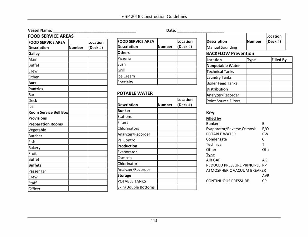
VSP 2018 Construction Guidelines
114
Vessel Name: _______________________________________ Date: ______________________ FOOD SERVICE AREAS FOOD SERVICE AREA Description Number
Location (Deck #)
Galley Main Buffet Crew Other Bars Pantries Bar Deck Ice Room Service Bell Box Provisions Preparation Rooms Vegetable Butcher Fish Bakery Fruit Buffet Buffets Passenger Crew Staff Officer
FOOD SERVICE AREA Location Description Number (Deck #) Others Pizzeria Sushi Grill Ice Cream Specialty
POTABLE WATER Location
Description Number (Deck #) Bunker Stations Filters Chlorinators Analyzer/Recorder PH Control Production Evaporator Osmosis Chlorinator Analyzer/Recorder Storage POTABLE TANKS Skin/Double Bottoms
Location Description Number (Deck #) Manual Sounding BACKFLOW Prevention Location Type Filled By Nonpotable Water Technical Tanks Laundry Tanks Boiler Feed Tanks Distribution Analyzer/Recorder Point Source Filters
Key Filled by Bunker B Evaporator/Reverse Osmosis E/O POTABLE WATER PW Condensate C Technical T Other Oth Type AIR GAP AG REDUCED PRESSURE PRINCIPLE RP ATMOSPHERIC VACUUM BREAKER
AVB CONTINUOUS PRESSURE CP

VSP 2018 Construction Guidelines
115
Vessel Name: _______________________________________ Date: ______________________ BACKFLOW PREVENTION
System Type Location (Deck #)
A/C Expansion Tank Beauty Salon Deckwashing Taps Fuel Oil Separator Lube Oil Separator Hood Cleaning Hospital Hydrophore Tank International Shore Con. Laundry (Main) Launderettes Photo Lab Toilets Multiflow Pulper System Showers Steam Generators (Spas) WHIRLPOOL SPAS SWIMMING POOLS Sprinkler System High Saline Discharge (Evap) Mineralizer Garbage Room Others
Key Type of BACKFLOW Preventer AIR GAP AG REDUCED PRESSURE PRINCIPLE RP ATMOSPHERIC VACUUM BREAKER AVB CONTINUOUS PRESSURE Type CP Noncontinuous Pressure Type NCP None Required NR
Recreational Waters SWIMMING POOLS Description No. Location
(Deck #) Fresh Water Pools HALOGENATION Y/N Chlorine Bromine Recorder
Seawater Pools
Description No. Location (Deck #)
Flow Through Recirculation HALOGENATION Y/N Chlorine Bromine Recorder
Fresh/Seawater Pools
Description No. Location (Deck #)
Flow Through Recirculation HALOGENATION Y/N Chlorine Bromine Recorder
WHIRLPOOL SPAS
HALOGENATION No. Location (Deck #)
Chlorine Bromine Recorder
SPA/POOL
HALOGENATION No. Location (Deck #)
Chlorine Bromine Recorder
Gross Registered Tonnage:
Max Passengers:
Max Crew:

VSP 2018 Construction Guidelines
116
Vessel Name: _______________________________________ Date: ______________________
Miscellaneous
Description No. Location (Deck #)
Children’s Areas Activity Center Care Center Decorative Fountains Housekeeping Handwash Stations Ventilation Units Y/N ACCESSIBLE