u.s. army armament research, development · pdf fileslop from elevating or traversing. ......
TRANSCRIPT
Act like someone’s life depends on what we do.
UNPARALLELED
COMMITMENT & SOLUTIONS
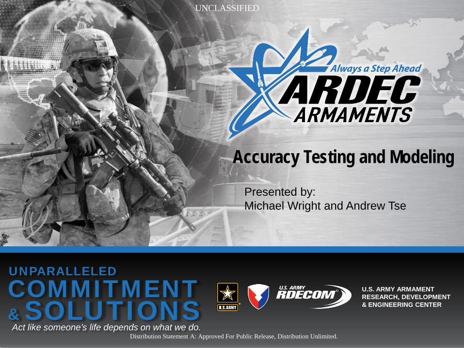
U.S. ARMY ARMAMENT RESEARCH, DEVELOPMENT & ENGINEERING CENTER
Presented by: Michael Wright and Andrew Tse
Accuracy Testing and Modeling
Distribution Statement A: Approved For Public Release, Distribution Unlimited.
UNCLASSIFIED

2
ACCURACY MODELS
Understanding Accuracy & Developing an Accuracy Model
Distribution Statement A: Approved For Public Release, Distribution Unlimited. UNCLASSIFIED
UNCLASSIFIED
3
THE QUANDARY AT HAND
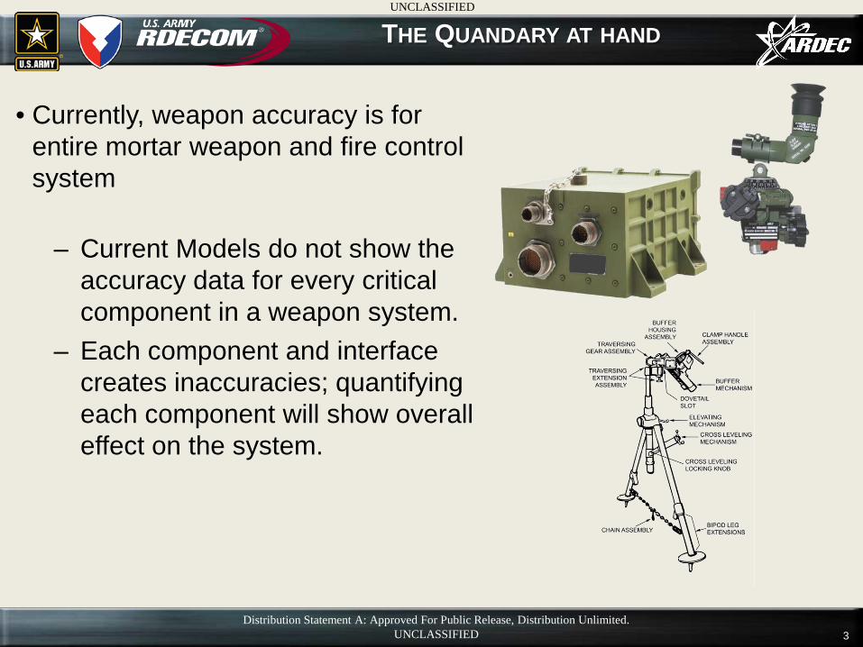
• Currently, weapon accuracy is for entire mortar weapon and fire control system
– Current Models do not show the accuracy data for every critical component in a weapon system.
– Each component and interface creates inaccuracies; quantifying each component will show overall effect on the system.
UNCLASSIFIED
Distribution Statement A: Approved For Public Release, Distribution Unlimited. UNCLASSIFIED
4
WEAPON CHARACTERISTICS ON ACCURACY
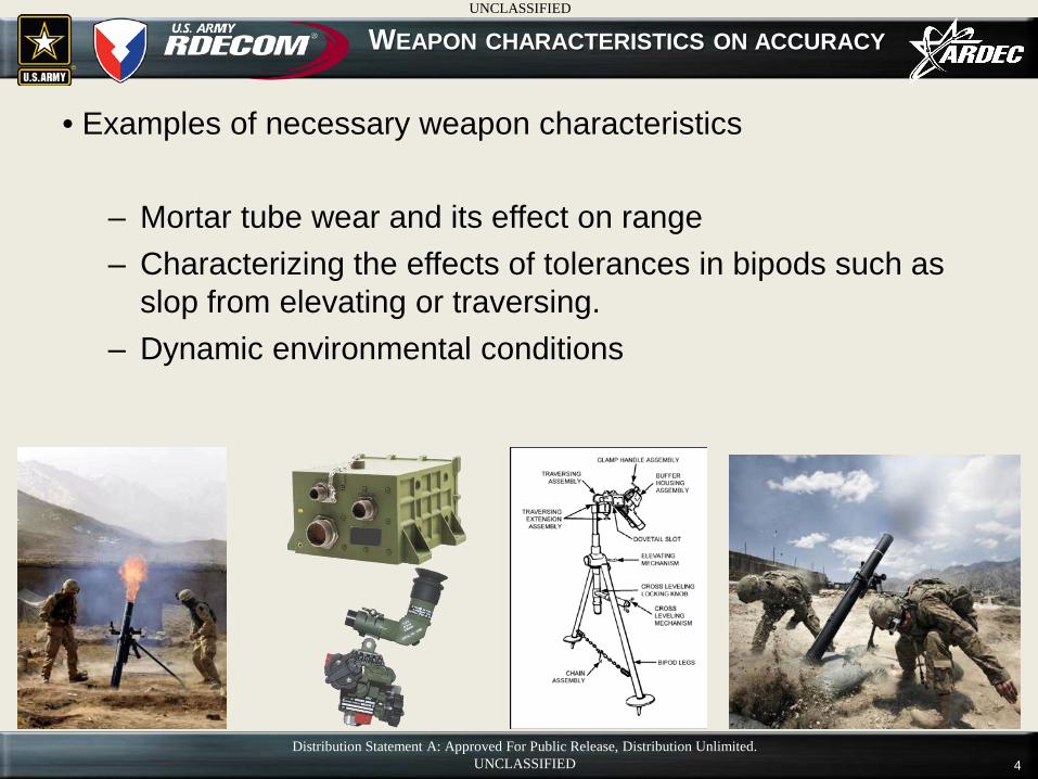
• Examples of necessary weapon characteristics
– Mortar tube wear and its effect on range – Characterizing the effects of tolerances in bipods such as
slop from elevating or traversing. – Dynamic environmental conditions
UNCLASSIFIED
Distribution Statement A: Approved For Public Release, Distribution Unlimited. UNCLASSIFIED
5
ACCURACY MODEL
• Greater understanding of accuracy constraints and aiming tolerances
– Better improvement planning, i.e. “greatest accuracy increase per dollar”
– Allows for precision effects without precision rounds Weapon modeling & simulation can assist in generating a ballistic kernel (BK) for accurate ballistic projection.
– Allows for greater accuracy for ballistic “dumb” rounds in dynamic environment
Increased accuracy is a necessity for increased range in order to maintain CEP
UNCLASSIFIED
Distribution Statement A: Approved For Public Release, Distribution Unlimited. UNCLASSIFIED

6
UNCERTAINTY QUANTIFICATION
Uncertainty Quantification (UQ)
Distribution Statement A: Approved For Public Release, Distribution Unlimited. UNCLASSIFIED
UNCLASSIFIED
7
UNCERTAINTY QUANTIFICATION
• The science of quantitative characterization and reduction of uncertainties.
– Attempts to determine a complete probability distribution of outcomes of a system.
– Utilizing simulations and experiments, UQ techniques determine likelihood of outcomes even though certain aspects of the system are unknown.
• e.g. When shooting mortars with the same direction, mortar
shell, and exit velocity, UQ determines the area of scatter for the shot due to unaccounted characteristics.
Distribution Statement A: Approved For Public Release, Distribution Unlimited. UNCLASSIFIED
UNCLASSIFIED

8
NEED FOR ORIENTATION MEASUREMENT SYSTEMS
• Accurate weapon laying during test events and data collection needs to be performed
– Minor errors during setup, bore sight, and control have a huge impact on accuracy.
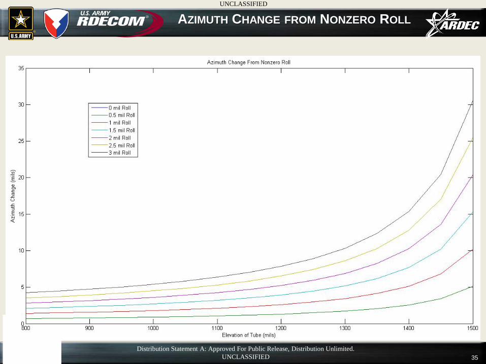
• 1 mil in roll error in the sight unit can translate to a 10 fold error in azimuth (AZ) error at highest elevation (EL)
– Utilize integrated sensors on the weapon system to give real time fidelity to digital fire control systems
• Sensors are now cheap & abundant and most are hardened to survive extreme conditions.
Distribution Statement A: Approved For Public Release, Distribution Unlimited. UNCLASSIFIED
UNCLASSIFIED
9
ACCURACY STUDY ON DISMOUNTED 120 MM MORTAR
• Currently tasked to conduct an accuracy study for the 120mm - Dismounted Mortar system
– Determine the effect of individual component error on the overall accuracy of the system.
– Conduct a repeatability study on multiple bipods on multiple cannons
– Conduct accuracy study on boresighting procedures – Tolerance stack up on interfaces and units of the optical
fire control and mortar systems – Utilize Uncertainty Quantification to combine data and
reduce uncertainty in variables and develop a model for mortar system performance
Distribution Statement A: Approved For Public Release, Distribution Unlimited. UNCLASSIFIED
UNCLASSIFIED

10
Current Orientation Measurement Systems
for Testing
Distribution Statement A: Approved For Public Release, Distribution Unlimited. UNCLASSIFIED
UNCLASSIFIED
11
CURRENT ORIENTATION MEASUREMENT SYSTEM
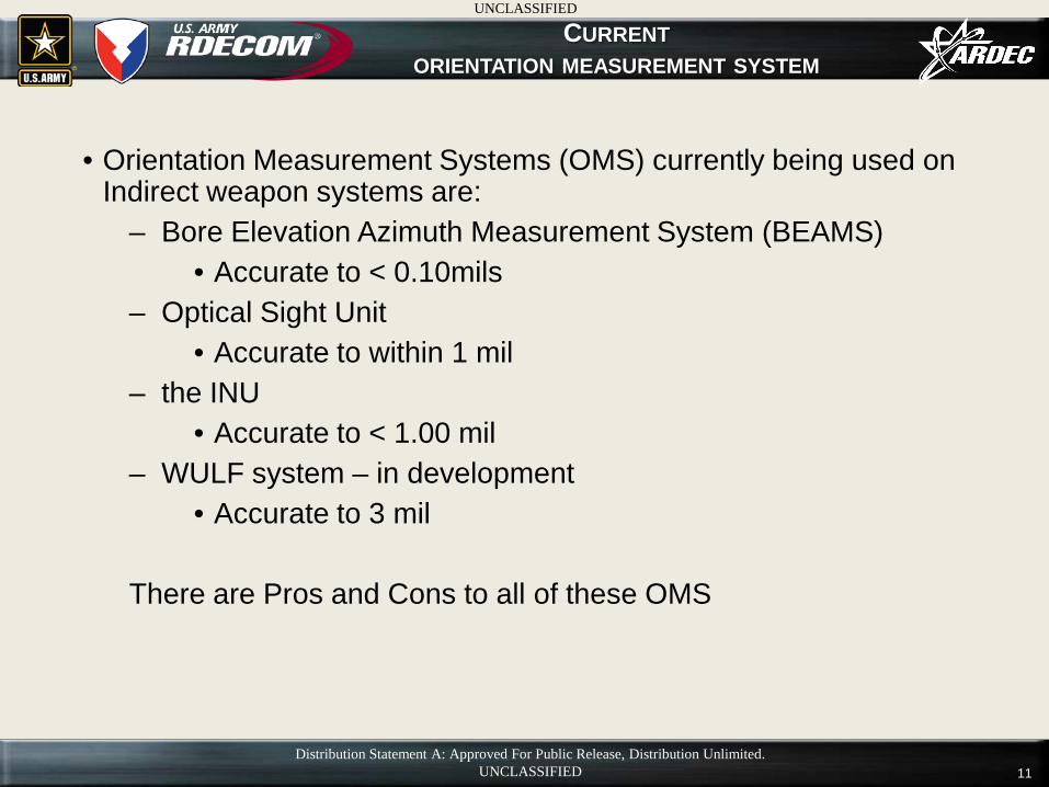
• Orientation Measurement Systems (OMS) currently being used on Indirect weapon systems are:
– Bore Elevation Azimuth Measurement System (BEAMS) • Accurate to < 0.10mils
– Optical Sight Unit • Accurate to within 1 mil
– the INU • Accurate to < 1.00 mil
– WULF system – in development • Accurate to 3 mil
There are Pros and Cons to all of these OMS
Distribution Statement A: Approved For Public Release, Distribution Unlimited. UNCLASSIFIED
UNCLASSIFIED
12
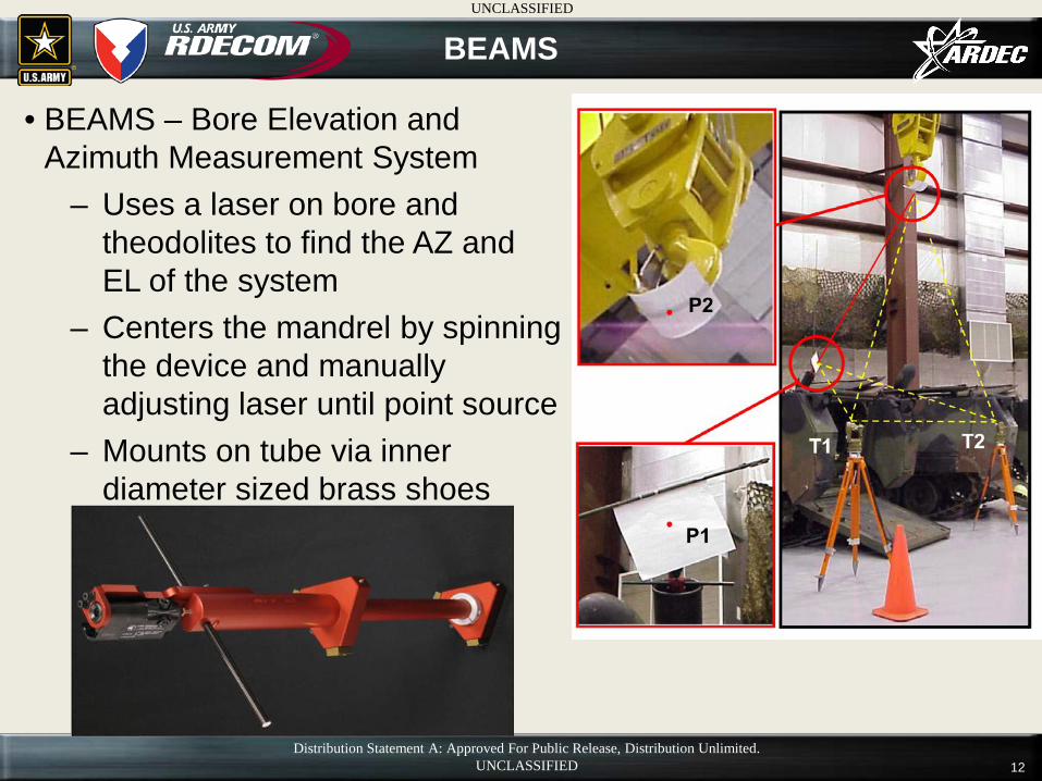
• BEAMS – Bore Elevation and Azimuth Measurement System
– Uses a laser on bore and theodolites to find the AZ and EL of the system
– Centers the mandrel by spinning the device and manually adjusting laser until point source
– Mounts on tube via inner diameter sized brass shoes
BEAMS
Distribution Statement A: Approved For Public Release, Distribution Unlimited. UNCLASSIFIED
UNCLASSIFIED
13
• BEAMS – Bore Elevation and Azimuth Measurement System Pros – First accurate system determining deflection and elevation to achieve
< 0.10 mils accuracy – Centers rod directly on bore axis – Theodolites can be placed arbitrarily, obtains Azimuth and Elevation
simultaneously
Cons – Long set up time – Springs in plungers may not be strong enough to maintain center of
bore. – Requires an optical target imaging screen or a varying elevated
platform to hold the second target sheet.
BEAMS
Distribution Statement A: Approved For Public Release, Distribution Unlimited. UNCLASSIFIED
UNCLASSIFIED
14
M67 OPTICAL SIGHT UNIT
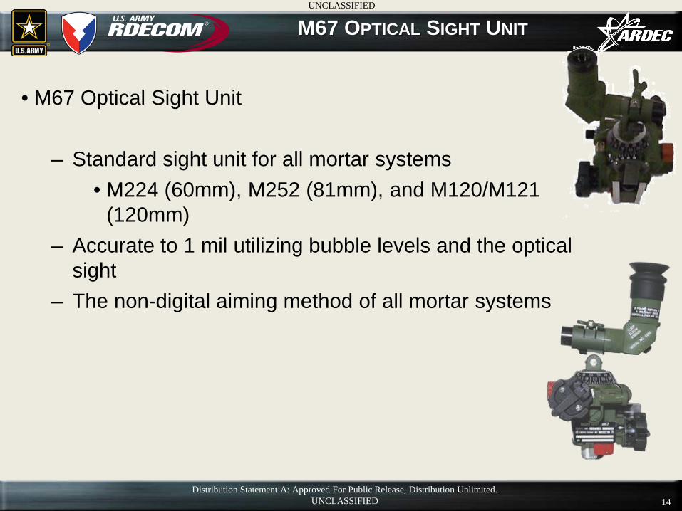
• M67 Optical Sight Unit
– Standard sight unit for all mortar systems • M224 (60mm), M252 (81mm), and M120/M121
(120mm) – Accurate to 1 mil utilizing bubble levels and the optical
sight – The non-digital aiming method of all mortar systems
Distribution Statement A: Approved For Public Release, Distribution Unlimited. UNCLASSIFIED
UNCLASSIFIED
15
M67 OPTICAL SIGHT UNIT
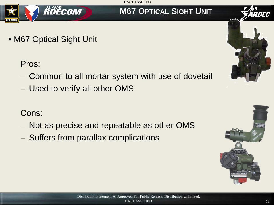
• M67 Optical Sight Unit Pros: – Common to all mortar system with use of dovetail – Used to verify all other OMS
Cons: – Not as precise and repeatable as other OMS – Suffers from parallax complications
Distribution Statement A: Approved For Public Release, Distribution Unlimited. UNCLASSIFIED
UNCLASSIFIED
16
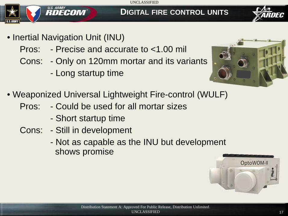
DIGITAL FIRE CONTROL UNITS
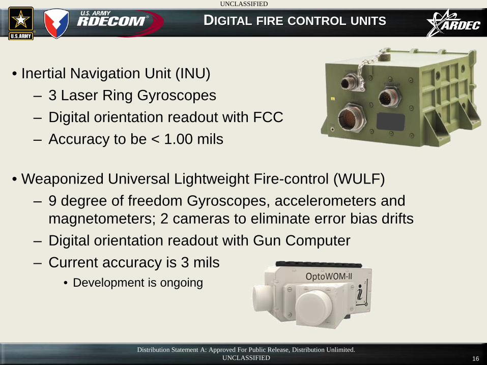
• Inertial Navigation Unit (INU) – 3 Laser Ring Gyroscopes – Digital orientation readout with FCC – Accuracy to be < 1.00 mils
• Weaponized Universal Lightweight Fire-control (WULF)
– 9 degree of freedom Gyroscopes, accelerometers and magnetometers; 2 cameras to eliminate error bias drifts
– Digital orientation readout with Gun Computer – Current accuracy is 3 mils
• Development is ongoing
Distribution Statement A: Approved For Public Release, Distribution Unlimited. UNCLASSIFIED
UNCLASSIFIED
17
DIGITAL FIRE CONTROL UNITS
• Inertial Navigation Unit (INU) Pros: - Precise and accurate to <1.00 mil Cons: - Only on 120mm mortar and its variants - Long startup time
• Weaponized Universal Lightweight Fire-control (WULF)
Pros: - Could be used for all mortar sizes - Short startup time Cons: - Still in development - Not as capable as the INU but development
shows promise
Distribution Statement A: Approved For Public Release, Distribution Unlimited. UNCLASSIFIED
UNCLASSIFIED
18
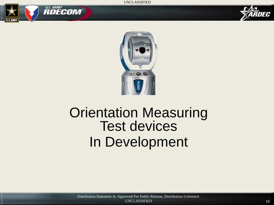
Orientation Measuring Test devices
In Development
Distribution Statement A: Approved For Public Release, Distribution Unlimited. UNCLASSIFIED
UNCLASSIFIED
19
ORIENTATION MEASUREMENT SYSTEM IN DEVELOPMENT
• Orientation Measurement Systems
– FARO Vantage Laser Tracker with self-centering mandrel • Absolute accuracy to be ~0.1 mils depending on the
tolerances of the mandrel. • Relative accuracy is < 0.1 mils
– Theodolite Mortar Laying System
• Accurate to within 0.10 mils depending on the accuracy of the roll vial on the tube fixture.
Distribution Statement A: Approved For Public Release, Distribution Unlimited. UNCLASSIFIED
UNCLASSIFIED
20
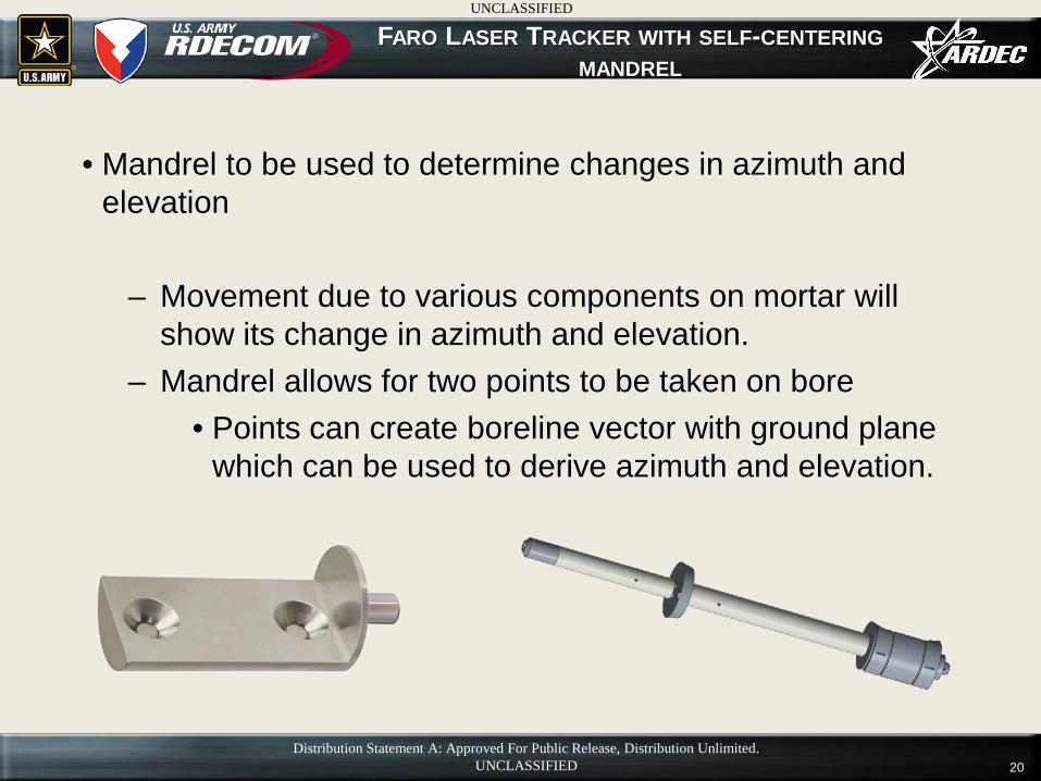
FARO LASER TRACKER WITH SELF-CENTERING MANDREL
• Mandrel to be used to determine changes in azimuth and elevation
– Movement due to various components on mortar will show its change in azimuth and elevation.
– Mandrel allows for two points to be taken on bore • Points can create boreline vector with ground plane
which can be used to derive azimuth and elevation.
Distribution Statement A: Approved For Public Release, Distribution Unlimited. UNCLASSIFIED
UNCLASSIFIED
21
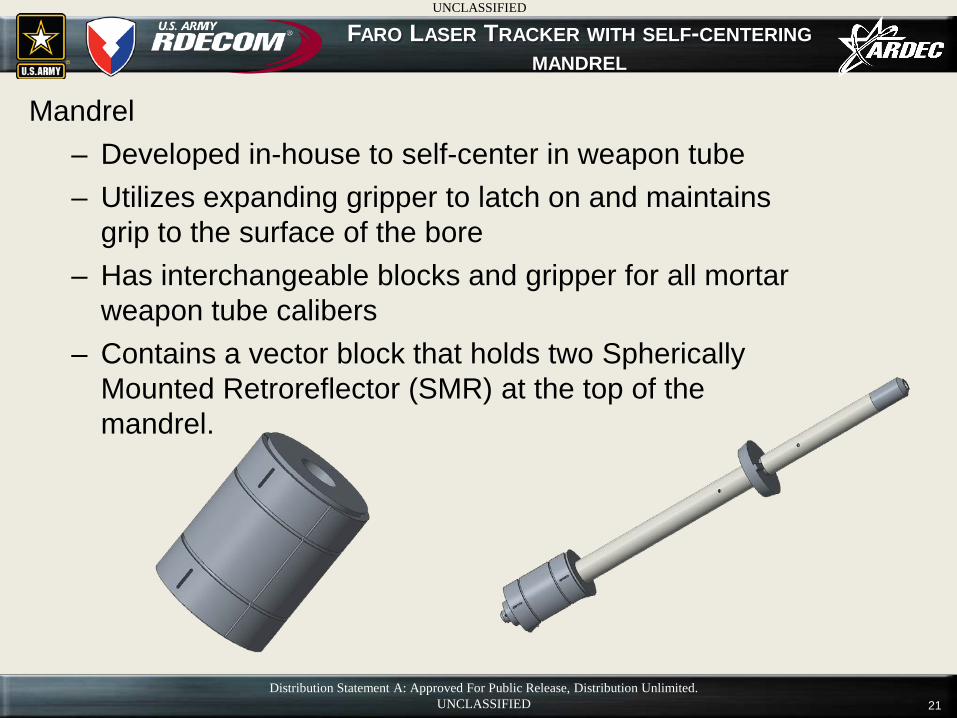
Mandrel – Developed in-house to self-center in weapon tube – Utilizes expanding gripper to latch on and maintains
grip to the surface of the bore – Has interchangeable blocks and gripper for all mortar
weapon tube calibers – Contains a vector block that holds two Spherically
Mounted Retroreflector (SMR) at the top of the mandrel.
FARO LASER TRACKER WITH SELF-CENTERING MANDREL
Distribution Statement A: Approved For Public Release, Distribution Unlimited. UNCLASSIFIED
UNCLASSIFIED
22
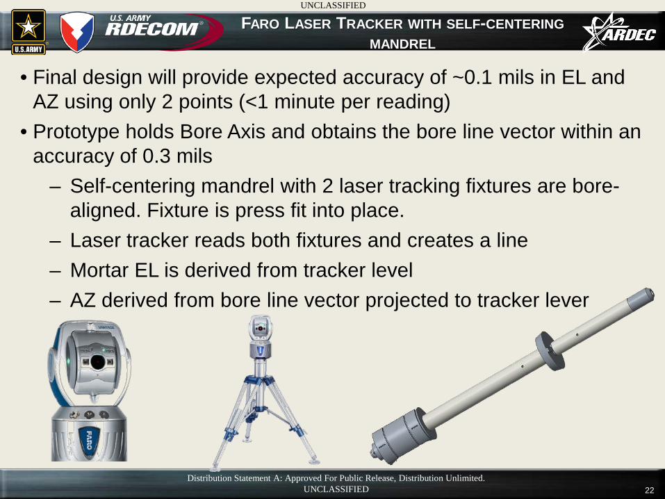
• Final design will provide expected accuracy of ~0.1 mils in EL and AZ using only 2 points (<1 minute per reading)
• Prototype holds Bore Axis and obtains the bore line vector within an accuracy of 0.3 mils
– Self-centering mandrel with 2 laser tracking fixtures are bore-aligned. Fixture is press fit into place.
– Laser tracker reads both fixtures and creates a line – Mortar EL is derived from tracker level – AZ derived from bore line vector projected to tracker lever
FARO LASER TRACKER WITH SELF-CENTERING MANDREL
Distribution Statement A: Approved For Public Release, Distribution Unlimited. UNCLASSIFIED
UNCLASSIFIED
23
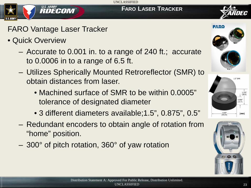
FARO Vantage Laser Tracker • Quick Overview
– Accurate to 0.001 in. to a range of 240 ft.; accurate to 0.0006 in to a range of 6.5 ft.
– Utilizes Spherically Mounted Retroreflector (SMR) to obtain distances from laser.
• Machined surface of SMR to be within 0.0005” tolerance of designated diameter
• 3 different diameters available;1.5”, 0.875”, 0.5” – Redundant encoders to obtain angle of rotation from
“home” position. – 300° of pitch rotation, 360° of yaw rotation
FARO LASER TRACKER
Distribution Statement A: Approved For Public Release, Distribution Unlimited. UNCLASSIFIED
UNCLASSIFIED
24
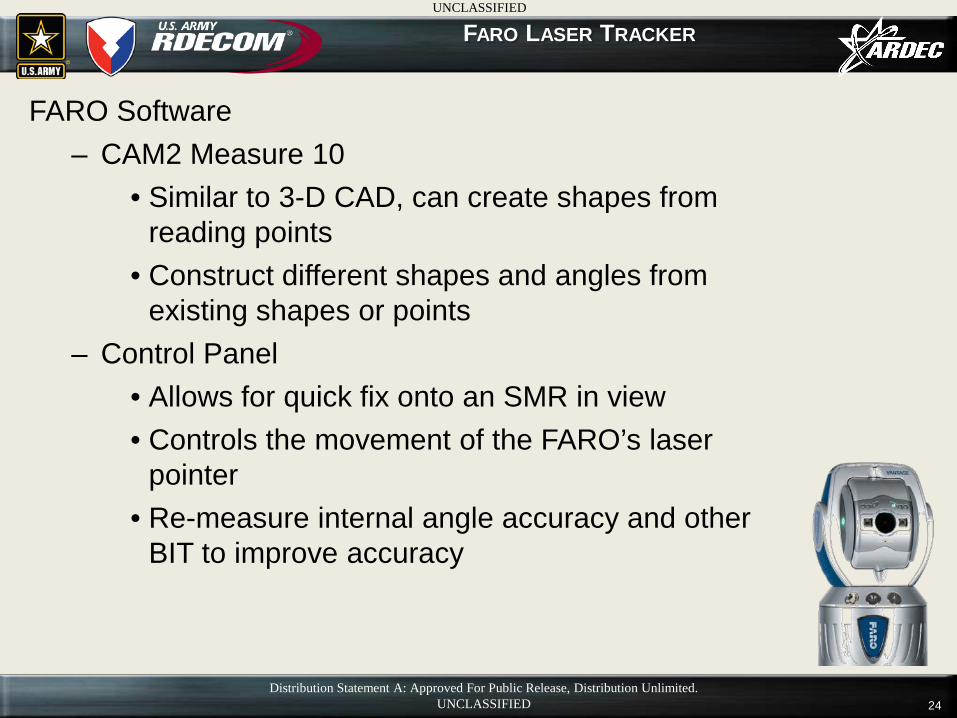
FARO Software – CAM2 Measure 10
• Similar to 3-D CAD, can create shapes from reading points
• Construct different shapes and angles from existing shapes or points
– Control Panel • Allows for quick fix onto an SMR in view • Controls the movement of the FARO’s laser
pointer • Re-measure internal angle accuracy and other
BIT to improve accuracy
FARO LASER TRACKER
Distribution Statement A: Approved For Public Release, Distribution Unlimited. UNCLASSIFIED
UNCLASSIFIED
25
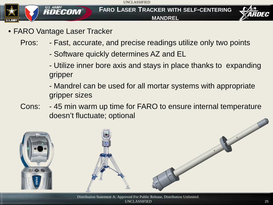
• FARO Vantage Laser Tracker Pros: - Fast, accurate, and precise readings utilize only two points - Software quickly determines AZ and EL - Utilize inner bore axis and stays in place thanks to expanding
gripper - Mandrel can be used for all mortar systems with appropriate
gripper sizes Cons: - 45 min warm up time for FARO to ensure internal temperature
doesn’t fluctuate; optional
FARO LASER TRACKER WITH SELF-CENTERING MANDREL
Distribution Statement A: Approved For Public Release, Distribution Unlimited. UNCLASSIFIED
UNCLASSIFIED
26
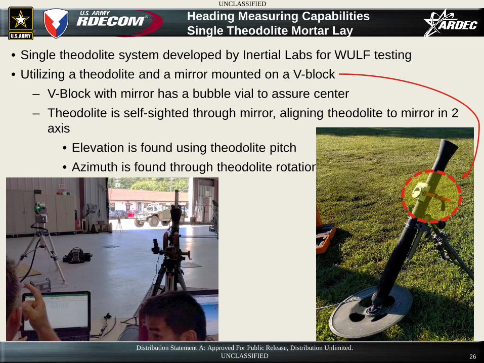
• Single theodolite system developed by Inertial Labs for WULF testing • Utilizing a theodolite and a mirror mounted on a V-block
– V-Block with mirror has a bubble vial to assure center – Theodolite is self-sighted through mirror, aligning theodolite to mirror in 2
axis • Elevation is found using theodolite pitch • Azimuth is found through theodolite rotation
Heading Measuring Capabilities Single Theodolite Mortar Lay
Distribution Statement A: Approved For Public Release, Distribution Unlimited. UNCLASSIFIED
UNCLASSIFIED
27
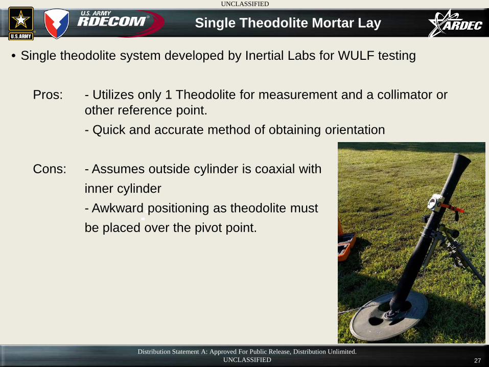
• Single theodolite system developed by Inertial Labs for WULF testing
Pros: - Utilizes only 1 Theodolite for measurement and a collimator or other reference point.
- Quick and accurate method of obtaining orientation Cons: - Assumes outside cylinder is coaxial with inner cylinder - Awkward positioning as theodolite must be placed over the pivot point.
Single Theodolite Mortar Lay
Distribution Statement A: Approved For Public Release, Distribution Unlimited. UNCLASSIFIED
UNCLASSIFIED
28
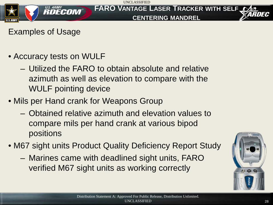
FARO VANTAGE LASER TRACKER WITH SELF CENTERING MANDREL
Examples of Usage • Accuracy tests on WULF
– Utilized the FARO to obtain absolute and relative azimuth as well as elevation to compare with the WULF pointing device
• Mils per Hand crank for Weapons Group – Obtained relative azimuth and elevation values to
compare mils per hand crank at various bipod positions
• M67 sight units Product Quality Deficiency Report Study – Marines came with deadlined sight units, FARO
verified M67 sight units as working correctly
Distribution Statement A: Approved For Public Release, Distribution Unlimited. UNCLASSIFIED
UNCLASSIFIED
29
FARO VANTAGE LASER TRACKER
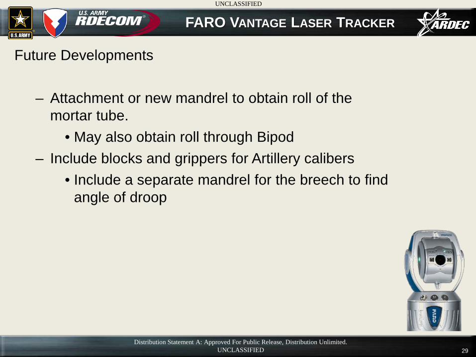
Future Developments
– Attachment or new mandrel to obtain roll of the mortar tube.
• May also obtain roll through Bipod – Include blocks and grippers for Artillery calibers
• Include a separate mandrel for the breech to find angle of droop
Distribution Statement A: Approved For Public Release, Distribution Unlimited. UNCLASSIFIED
UNCLASSIFIED
30
ACCURACY TESTING AND MODELING
Questions?
UNCLASSIFIED
Distribution Statement A: Approved For Public Release, Distribution Unlimited. UNCLASSIFIED
31
• Backup slides
UNCLASSIFIED
Distribution Statement A: Approved For Public Release, Distribution Unlimited. UNCLASSIFIED
32
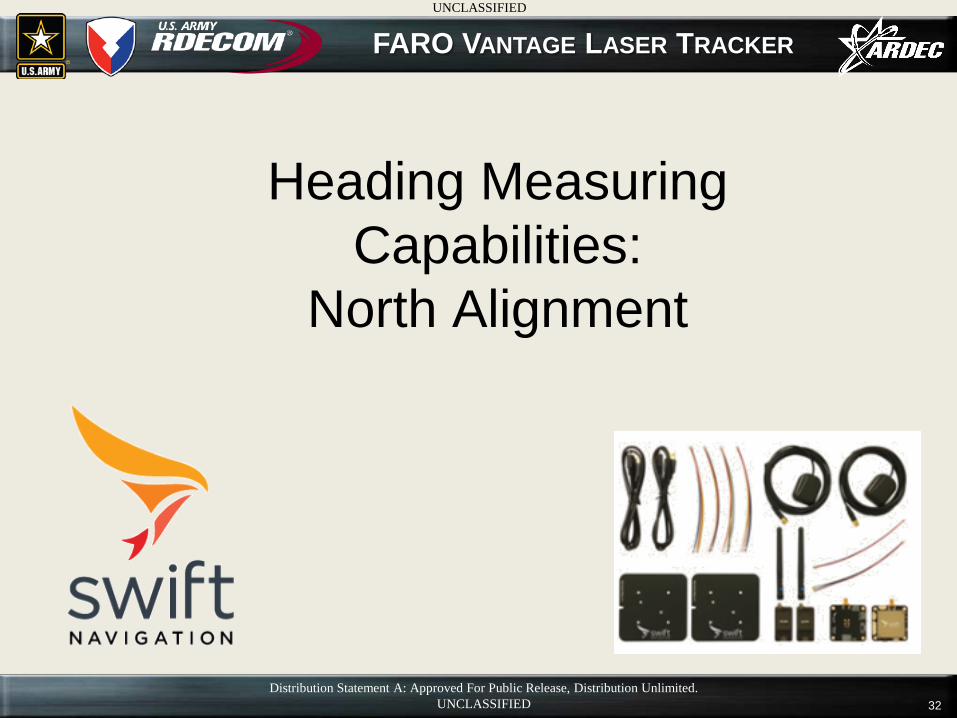
FARO VANTAGE LASER TRACKER
Heading Measuring Capabilities:
North Alignment
Distribution Statement A: Approved For Public Release, Distribution Unlimited. UNCLASSIFIED
UNCLASSIFIED

33
• Base line north vector found using 2 RTK GPS systems mounted onto theodolites, <1 mil @ 2 meters to true north
– Theodolites aligned to each other defining north vector – Base theodolite then swung to point at a measurement system – Azimuth line from measurement system to theodolite is then
defined – Can be used with any surveying equipment I.E. FARO,
Theodolite
Heading Measuring Capabilities North Alignment
UNCLASSIFIED
Distribution Statement A: Approved For Public Release, Distribution Unlimited. UNCLASSIFIED
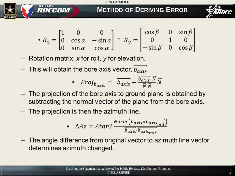
34
METHOD OF DERIVING ERROR
Distribution Statement A: Approved For Public Release, Distribution Unlimited. UNCLASSIFIED
UNCLASSIFIED
35
AZIMUTH CHANGE FROM NONZERO ROLL
Distribution Statement A: Approved For Public Release, Distribution Unlimited. UNCLASSIFIED
UNCLASSIFIED