us 5147007
DESCRIPTION
jTRANSCRIPT

United States Patent [191 Kahrs et al.
lllllllllllllllllllllllllllllllllllllllllllllllllllllllllllllllllllllllllll US005147007A
[11] Patent Number:
[45] Date of Patent: 5,147,007
Sep. 15, 1992
[54] HYDRAULICALLY ASSISTED STEERING SYSTEM FOR AUTOMOTIVE VEHICLES
[75] Inventors: Manfred Kahrs, Wiesbaden; Lothar Kunze, Hofheim-Langehain; Joachim Baier, Hanau; Gerhard Kunz, Linden; Bernhard Moeller, Frankfurt am Main; Wilhelm Beer, Ruesselsheim; Hans-G. Krines, Usingen; Gerhardt Schudt, Hanau, all of Fed. Rep. of Germany
[73] Assignee: Alfred Teves GmbH, Frankfurt Am Main, Fed. Rep. of Germany
499,383
Sep. 14, 1989
[21] Appl. No‘:
[22] PCT Filed:
[86] PCT No.: PCT/EP89/01069
§ 371 Date: Jun. 1, 1990
§ 102(e) Date: Jun. 1, 1990
[87] PCT Pub. No.: WO90/03908
PCT Pub. Date: Apr. 19, 1990
[30] Foreign Application Priority Data Oct. 4, 1988 [DE] Fed. Rep. of Germany ..... .. 3833637
Dec. 24, 1988 [DE] Fed. Rep. of Germany ..... .. 3843893 Aug. 28, 1989 [DE] Fed. Rep. of Germany ..... .. 3928376
[51] Int. Cl.5 ............................................. .. B62D 5/06
[52] us. c1. .................................. .. 180/132; 180/148; 280/91
[58] Field of Search .............. .. 180/148, 132; 280/661, _ 280/91
[56] References Cited U.S. PATENT DOCUMENTS
4,634,135 1/1987 Nakata et a1. ..................... .. 180/148
4,646,868 3/1987 Rosell ....... .. .. 180/148
4,694,925 9/1987 Roberts ........ ..
4,823,898 4/1989 Ogura et a1. 4,856,608 8/1989 Adams ..... ..
4,981,189 1/1991 Wilder ............................... .. 180/148
Primary Examiner—Mitchell J. Hill Attorney, Agent, or Firm-Robert P. Seitter; J. Gordon Lewis
[57] ABSTRACT A hydraulic power steering system for automotive ve hicles wherein the hydraulic power assistance takes place only above a predetermined steering power. A power cylinder (6) is coupled to a mechanical steering assembly, a pump (19, 36), and a control valve (12)‘ In order to achieve safety in operation and a simple ar rangement of the power steering system, a slide of a component (2) of the mechanical steering assembly is slidable with respect to the vehicle body. The slide is effected by the steering power overcoming a prestress ing power, serves for the mechanical actuation of the control valve (12).
28 Claims, 14 Drawing Sheets

US. Patent Sep.15,1992 Sheet 1 of 14 5,147,007
Z5 HYDRAULIC BRAKE SYSTEM SUPPLY
1jIrFJI71/1IIr1lI/7
FIG-1

US. Patent Sep. 15,1992 Sheet 3 of 14 5,147,007
FIG-5

US. Patent Sep. 15, 1992 Sheet 4 of 14 5,147,007
QIOE
US. Patent Sep.15, 1992 Sheet 5 of 14 5,147,007
FIG-5

US. Patent Sep. 15, 1992 Sheet 6 of 14 5,147,007
72 w
70 7/
F—l> ‘<l-F
75 75
FIG-6
7472 _____>g_
'\
'77
:“73 y __
FIG-8

US. Patent Sep. 15, 1992 Sheet 7 0f 14 5,147,007
FIG-9

US. Patent Sep. 15, 1992 Sheet 8 of 14 5,147,007
‘WE L455?!“

US. Patent Sep. 15, 1992 Sheet 9 of 14 5,147,007

US. Patent Sep. 15, 1992 Sheet 10 of 14 5,147,007
FIG-12

US. Patent Sep.15,1992 Sheet 11 of 14 5,147,007


US. Patent Sep. 15, 1992 Sheet 13 of 14 5,147,007
"III 1
‘FIG ~17

US. Patent Sep. 15, 1992 Sheet 14 of 14 5,147,007

5,147,007 1
HYDRAULICALLY ASSISTED STEERING SYSTEM FOR AUTOMOTIVE VEHICLES
BACKGROUND OF THE INVENTION
The present present invention relates to a hydraulic power steering system for automotive vehicles includ ing a power cylinder coupled to a mechanical steering assembly, a pump and a control valve. A hydraulic power steering system of this type is
known from published German patent application No. 28 39 121. This known power steering system is com prised of a measured variable transmitter depending on the angle of rotation. The transmitter serves as a sensor for the hand power applied to the steering wheel. The output signal is transmitted to an electronic control module which controls the solenoid valves which are located between the pump and the power cylinder. In addition to their sophisticated and cost-intensive ar rangements, these known power steering systems have the disadvantage that the steering assembly may be come locked in the event of a defect of the electronic control module. Although this risk could be avoided by the redundant design of the electronic control system, the resulting increased sophistication would neverthe less result in a further disadvantage.
It is, therefore, an object of the present invention to provide a hydraulic power steering system for automo tive vehicles of the type described above which is dis tinguished by a simple arrangement and which ensures safety in operation. In particular, the hydraulic power assistance dependent on demand is controlled without sophisticated electronic modules.
SUMMARY OF THE INVENTION
In a preferred embodiment of the invention it is envis aged that one of two valve elements slidable relative to each other is secured to the slidable component, while the other valve element is pivoted on the vehicle body. In this way, the control valve is actuated directly start ing from a steering power determined by the prestress ing power. The power ?ux is transmitted through a very restricted number of components. According to a preferred embodiment of the present
invention, the steering gear of the mechanical steering assembly is elastically slidably supported at the vehicle. The hydraulic unit, with at least one of two valve ele ments being slidable relative to each other, is rigidly secured to the steering gear. The other valve element is coupled to the vehicle body. This embodiment allows for the arrangement of an element generating the pre stressing power both between the vehicle body and one valve element and between the two valve elements A highly effective silencing is attained by an elastic con nection between the vehicle body and the steering gear, the hydraulic unit being rigidly coupled to the steering gear.
In order to obtain an integrated hydraulic unit as compact as possible and comprising any components required for control, it is advantageous when the steer ing gear is supported at the vehicle body so as to be slidable in the transverse axis of the vehicle. This is particularly advantageous when the housing of the con trol valve is rigidly coupled to the steering gear and when the control element is coupled to the vehicle and is slidable within the housing of the control valve and is elastically prestressed in both sliding directions against
5
35
45
55
65
2 the housing of the control valve or against a component being rigidly coupled to the latter. By this embodiment, a completely preassembled, oil-?lled and functionally tested hydraulic unit is provided which is ready for operation and does not require measures other than to be mounted a the vehicle with simple assembly opera tions and to be connected thereto. One embodiment of the present invention which pro
vides for the steering gear to be rigidly coupled to the vehicle body entails that one section of the steering axle is slidably supported and that the slide actuates the control valves in response to a force component which results from the steering power. Steering gears particu larly suited to generate components of force of reaction of this kind are either designed as helical rack-and-pin ion gears or as ball-type planetary gearings. In both designs, a component of the force of reaction being proportional to the steering power as to size and direc tion is generated in the steering axle which is utilized to in?uence the control valve preferably integrated in the steering axle or in the steering axle housing in this case. Depending on the specific type of application, different designs of the spring elements are possible for the pur pose of generating the prestressing force which is brought to bear on the slidable component. According to a further embodiment which is particu
larly advantageous in regard to road behavior, the pre stressing is effected by means of a captivated spring element. In this manner, a prestressing also exists in the neutral position. This means that the control valve is actuated only starting from a minimum steering power, as a result of which provision a start of the hydraulic power assistance is, for example, avoided in the event of steering corrections which result from the impact of lateral wind at elevated speeds, unbalances of a wheel or wheels or the like. Without this minimum steering power threshold, an unstable oscillation of the steering action would be possible by an alternating switching-in of the hydraulic power assistance and countersteering on the part of the driver. Since the energy supply of the hydraulic unit takes place exclusively in the event of a demand for power assistance, it is provided that an electric switch switching the pump is actuatable by the control element or spring element. In an advantageous embodiment of the present invention, the control valve is designed as a 3/ 3-way valve in the shape of a longitu dinal slide valve. Alternatively, a valve designed as a double-seated valve is suitable for use in the hydraulic power steering system, because in that case a simple pivoting of the control element on the vehicle body is possible. A particularly simple con?guration of the inventive
power steering system is attained if and when a revers ible pump is provided whose sense of rotation depends on the sense of steering. In this con?guration, the con trol element of the control valve actuates a switch hav ing three switching positions. An embodiment of the invention in which the slidable component of the me chanical steering assembly is slidable only at a limited extent is particularly advantageous since only a deter mined part of the steering power takes support through the control valve in this case. Another embodiment of the present invention is distinguished by the control valve being elastically centered, the centering elastic arrangement being at least partly located in the power ?ux of the steering power in this context. Owing to this provision, the centering springs of the control valve

5,147,007 3
may, for example, serve for the mechanical steering by adequately dimensioning the prestressing of the slidable component, the prestressing power again forming the threshold value at which the hydraulic boosting will be activated. A particularly low-cost and compact design is
achieved for the power steering system in accordance with the present invention in that the elastic arrange ment is comprised of at least one spring taking support at two support plates. The support plates are prestressed against two stops of the housing of the control valve located at a distance from each other and stop surfaces of equal distance are provided at the control element of the control valve by means of which force is applied on the associated support plate in a direction contrasting that of the prestressing power.
In order to ensure the hydraulic fluid supply also with a pump having a low power consumption in the presence of elevated steering speeds and high hydraulic fluid demand, it is an advantage if an accumulator is interposed between the pump and the control valve. In order to avoid an undesired discharge of the accumula tor due to leakages at the control valve, a pilot valve is provided in a preferred embodiment of the present in vention between the accumulator and the control valve. When the hydraulic power steering system is run
with brake ?uid as a pressure fluid, then an energy supply can be provided by the pump of a hydraulic brake unit without segregation of the ?uids.
In another particularly favorable embodiment of the present invention, the mechanical steering assembly is arranged as a rack~and~pinion steering system with a driving pinion coupled to the steering axle and with a rack, wherein the torque transmission from the steering axle onto the driving pinion is effected by way of at least one pin which engages into radially extending recesses of both the driving pinion and the steering axle. One of these radial recesses is designed as a coulisse type guide extending transversely relative to the radial plane, and the steering axle supported on the driving pinion in an axially slidable and biassed manner and is connected with the control valve. As a result a power steering system is accomplished which is characterized by a compact and straight-forward design, yet requires only a minimum of modi?cations to the component parts of the mechanical steering gear, while most gear parts of a steering gear provided for use on the purely mechanical steering assembly are maintained in the power steering system.
This affords the possibility of obtaining an add-on hydraulic power steering system which involves very little modi?cation to the existing mechanical steering assembly. This solution is especially suitable for rack and-pinion steering systems in which the driving pinion is not helically geared.
In a power steering system comprising a helically geared driving pinion, a simple solution which involves only very few modi?cations of the steering gear can be obtained wherein the driving pinion is supported in the housing of the steering gear axially slidably by means of at least one roller bearing, wherein the external ring of the roller bearing is axially slidably supported in the housing and is acted upon by elastic means on either frontal ends, and wherein the internal bearing ring is axially ?xed on the driving pinion, with the driving pinion being coupled to the control valve.
If it is essentially impossible to modify the support of the driving pinion in the area of the housing, an embodi
0
t... 5
45
55
65
4 ment of this invention can be used wherein the internal ring of the roller bearing is supported axially slidably on the driving pinion, which is coupled to the control valve, and is acted upon on either frontal end by elastic means, and wherein the external ring of the bearing is axially ?xed in the housing.
In hydraulic power steering systems of this type, it is a particular advantage if the elastic application causes a preloading force to develop in the zero position of the steering system, that is, it essentially forms a power threshold. This can be achieved in particular by the use of captivated spring elements. Therefore, in a preferred embodiment of the present invention, the application of the frontal ends of the bearings of the driving shaft is performed by way of spacers which are movable to abut on a stop, with the distance of the stops corresponding to the width of the slidable bearing ring. As a result of these arrangements, a particularly simple centering of the control valve is realized.
In another embodiment of the present invention the steering axle end projecting from the steering gear housing does not perform an axial movement. To this end, it is arranged that the driving pinion coupled to the control valve is helically geared, that at least one por tion of the steering axle is rotatably but axially ?xedly supported in the steering gear, and in that the driving pinion is axially slidably supported in the portion of the steering axle and biassed in both axial directions of the motion. To prevent friction affects on the response behavior
of the hydraulic auxiliary power, in the area of the point of support of the driving pinion in the steering axle portion, both in the journal pin of the driving pinion and in the associated bearing area of the portion of the steer ing axle, at least one axially extending groove advanta geously is provided, into which at least one spherical carrier element respectively is inserted A particularly favorable embodiment of the present
invention is obtained if the control valve is connected coaxially with the driving pinion and serves to support the driving pinion in the housing of the steering gear.
BRIEF DESCRIPTION OF THE DRAWINGS
The functioning and further advantageous features of the present invention will now be described in the fol lowing detailed description made with reference to the accompanying drawing wherein: FIG. 1 shows a ?rst embodiment of the invention; FIG. 2 shows a second embodiment of the invention
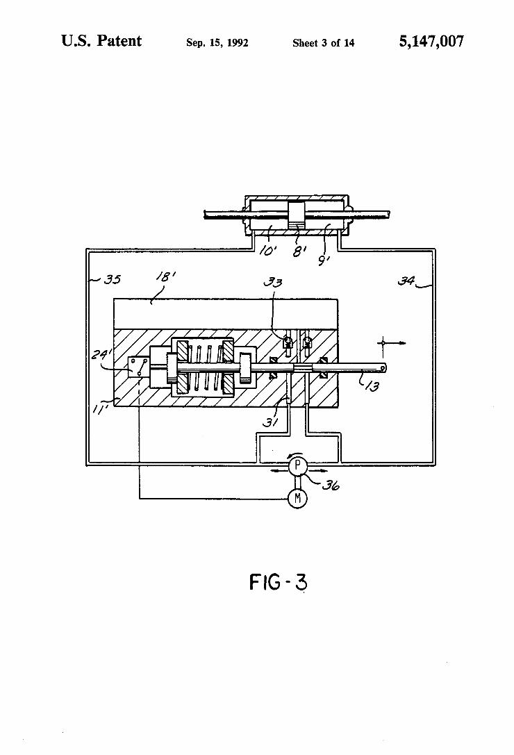
in the rest position or in the event of the steering mecha nism being operated without power assistance; FIG. 3 shows the second embodiment of the inven
tion in the switching position for an operation of the steering system with power assistance; FIG. 4 is a representation with several sections of the
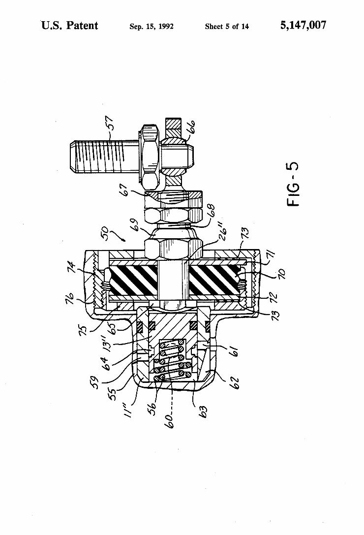
integrated hydraulic unit; FIG. 5 shows a cross section through an embodiment
of the inventive spring element in the shape of a capti vated spring and through the control valve; FIG. 6 to FIG. 8 show sections through a spring
element according to the present invention; FIG. 9 shows an embodiment of the invention with a
control valve coupled to the steering axle through the spring element; FIG. 10 shows an embodiment of the invention with
accumulator and centrally open control valve; FIG. 11 shows an embodiment of the invention with
centrally closed control valve;

5,147,007 5
FIG. 12 shows a diagram of forces useful in explain ing features of the present invention; FIG. 13 shows another embodiment; FIGS. 14 to 16 show each an enlarged representation
of a detail of FIG. 13; FIGS. 17 to 18 show still further embodiments of this
invention and, FIG. 19 shows a lateral partial view of the embodi
ment according to FIG. 18.
DETAILED DESCRIPTION
The hydraulic power steering system according to FIG. 1 is a mechanical steering assembly comprising a steering axle 1, a steering gear 2, and a steering tie rod 3. The steering tie rods are pivoted on steering arms of the wheel suspension (not shown). The steering gear is bolted or screwed by means of two clamps 4 and high— elasticity elements to the vehicle body 5. The high-elas ticity suspension of the steering gear 2 permits a certain slidability in the transverse direction of the vehicle. The power cylinder 6 is rigidly bolted or screwed to
the housing of the steering gear 2, while the piston rod 7 is rigidly coupled to the steering tie rod 3. At the other end of the piston rod 7, there is a power piston 8 which divides the power chambers 9 and 10 from each other within the power cylinder 6. The housing 11 of the control valve 12 is rigidly coupled to the power cylin der 6, respectively to the steering gear. Within the hous ing 11, the slidably arranged control slide valve 13 is prestressed against the housing in either direction of slide by means of two springs 14 having equal spring force, and is centered in the rest position. The control valve 12 is arranged in the shape of a
3/3-way valve, one connection being tied through the link 15 to the power chamber 9 of the power cylinder 6, while the other two connections are tied through the links 16 and 17 to the tank 18, respectively to the deliv ery connection of the pump 19. The power cylinder 6 is configurated in the shape of a differential cylinder, the power chamber 9 being associated with the larger pres surizing surface at the power piston, whereas the cross sectional area of the piston being associated with the power chamber 10 is half the size of the described pres surizing surface. From the intersection 20 of the link 17, a hydraulic ?uid line 21 leads to the power chamber 10 of the power cylinder 6. Between the links 16 and 17, two links are provided with an intake valve 22 being located in one of them and a pressure relief valve 23 in the other one. A ?lter element is arranged in the link between the tank 18 and the pump 19 driven by an electric motor. The electric drive of the pump 19 is actuated by the electric switch 24 through a relay 25. The switch is actuated by the slide of the control slide valve 13 out of the position of rest. The control slide valve 13 is pivoted on a point rigid with the vehicle by means of a reaction rod 26. As long as the steering system is not actuated or is
actuated with a very low hand power, the hydraulic power steering system is in the position of rest shown in the drawing. In this position, the pump 19 is switched off by the electric switch 24. The power chambers 9 and 10 are interconnected and connected to the tank hy draulically. A more elevated steering power is required when the steering assembly is operated, for example, while the vehicle is at rest or at very low speeds. In that case, the steering gear 2 will slide according to the steering direction within its elastic suspension at the vehicle body in a direction which is transverse to the
10
20
25
40
50
60
65
6 vehicle steering axis. Since the whole hydraulic unit, in particular the housing 11 of the control valve 12, is rigidly coupled to the steering gear 2, while the control slide valve 13 is pivoted in a point being rigid with the vehicle body, a slide of the housing 11 and of the con trol slide valve 13 relative to each other will occur starting from a steering power which exceeds the pre stressing of the associated spring 14. By this relative slide the electric motor driving the pump will be switched in, and, moreover, the control valve 12 will be brought into a switching position depending on the steering direction, in which position the power piston 8 is pressurizable by the pump pressure according to its active cross-sectional areas. As long as the pump 19 is switched in, the power
chamber 10 will remain pressurized, so that in the event of a switching position of the control valve 12 in which the power chamber 9 is in connection with the tank 18, a direction of motion of the power piston 8 will result in which the piston rod 7 is slid into the power cylinder 6. When, on the other hand, both the power chamber 10 and the power chamber 9 undergo the pump pressure, then the piston rod 7 will be slid out of the power cylin der 6. If during or after a steering motion the steering power exerted at the steering tie rod decreases to a value which is sufficient to overcome the prestressing of the associated spring 14, the control valve 12 will be restored into its position of rest, whereby the pump is switched off and the power chambers 9 and 10 are inter connected to each other and connected to the tank 18 again.
In the event of a steering operation without power assistance, the hydraulic ?uid will be transferred be tween the two power chambers without any pressure, the differential ?uid volume resulting from the volume of the piston rod being aspirated from the tank or dis charged into the tank depending on the steering direc tion. This applies both in case the manually exerted steering power is very low and in case of failure of the pump or of the electric energy supply of the driving motor. The embodiment according to FIGS. 2 and 3 shows
an arrangement of the power cylinder 6 in the shape of a synchronous cylinder. The mechanical part of the steering system is not illustrated in these two Figures. Like reference numerals are assigned to like elements in all three Figures. The part of the steering system not shown in the drawing corresponds to the arrangement of FIG. 1. In FIG. 2, the rest position is illustrated which comes about when the steering system is not actuated or when the steering system is actuated with a very low steering power. The control slide valve 13 which is sealedly guided within the housing 11 in a slidable way is furnished with a control groove by which the connection of the ducts 30 and 31 to the tank 18 is controllable. By-passing the control slide valve 13, the ducts 30 and 31 are connected to the tank 18 through the non-return valves 32 and 33. In this con?g uration, non-return valves 32 and 33 are arranged such that they block the ?ow direction from the associated duct to the tank 18. The duct 30 is connected to the hydraulic ?uid link 34 which is provided between the reversible pump 36 and the power chamber 9. The duct 31 is connected to the hydraulic ?uid link 35 between the power chamber 10 and the reversible pump 36. The tank 18 is integrated in the housing 11. The control slide valve 13 presenting a plurality of
steps is guided by the centering chamber 38 arranged in

5,147,007 7
the housing 11. At the one end of centering chamber 38 an electric switch 24 is located which is connected to one end of control slide valve 13 and which switches the electric motor driving the pump. At the other end of the control slide valve 13 there is the pivotal point 37 which is coupled to the vehicle body. The stepped centering chamber 38 presents two stops
39 and 40 at each of which one of the two associated supporting plates 41 and 42 takes support which are subject to the pressure exerted by the compression spring 43 being arranged between the two supporting plates. On either side of the supporting plates 41, 42, two steps are provided at the control slide valve is guided by the supporting plates whose stop surfaces 44, 45 facing said supporting plates are disposed at the same distance from each other as the stops 39 and 40. As long as the supporting plates 41 and 42 are abutted against the associated stops 39, 40 the control valve, respec tively, the control groove will be in the position of rest in which the pump is switched off. Without power assistance the hydraulic ?uid will be displaced between the two power chambers without pressure during this time. The mode of functioning of the second inventive
embodiment of the present invention corresponds to that of the embodiment described with reference to FIG. 1. As soon as the steering power applied exceeds a determined value, the control slide valve will be slid in one or the other direction depending on the steering direction, against the prestressing force of the spring 43. One switching position is illustrated in FIG. 3. In this switching mode, the power piston 8 according to the illustration in FIG. 3 is slid to the right. In accordance with the steering power applied, the housing 11 coupled to the elastically suspended steering gear 2 will slide to the left, while the control slide valve will maintain its position due to its being rigidly pivoted on the vehicle. As a consequence of the relative motion between the control slide valve 13 and the housing 11, the electric switch 24 will be actuated, whereby the reversible pump 36 will be driven in a sense of rotation by which it conveys into the hydraulic ?uid link 35 and, thus, into the power chamber 10. The duct 31 is separated from the tank 18 in this switching position, while the duct 30 and, consequently, the power chamber 9 are connected to the tank 18. The volume of hydraulic ?uid displaced from the power chamber 9 is fed to the tank 18 over the forementioned connection. If the pump 36 should meet with a failure in an operating condition of this kind, then the hydraulic ?uid would have to be displaced out of the power chamber 9 without power assistance, that is, only by hand power into the tank 18, while the power chamber 10 may aspirate hydraulic ?uid from the tank 18 through the non-return valve 33. When the steering direction is inverted, the housing
11 is slid in the other direction, as a result of which the reversible pump 36 is switched into the other sense of rotation so that it delivers into the power chamber 9. Also the switching of the ducts 30, 31 will so be in verted. Alternatively, it will of course be possible to couple the control slide valve 13 to the slidable steering gear 2 and to ?x the housing 11 to the vehicle. FIG. 4 shows a particularly compact arrangement of
the invention arranged as an integrated unit around the steering gear 2. Steering gear 2 is designed as a rack and-pinion gear, the driving pinion coupled to the steer‘ ing axle being arranged within the housing of the steer ing gear and engaging the rack. By means of an adjust
0
25
40
45
55
60
65
8 ing apparatus 54, a thrust member acting on the rack allows adjustment in such a manner as to create freedom for play between the rack and the driving pinion. On the left side when viewed in the drawing, the rack projects out of the housing of the steering gear 2. The piston rod 7 and the two steering tie rods 3 are ?anged to that projecting end (not shown in the drawing). The steering tie rod illustrated in FIG. 4 is coupled to the steering arm of the left front wheel. The steering gear 2 is cou pled to the vehicle body such as to be elastically slidable in transverse direction. On the contrary, the hydraulic unit is rigidly coupled to the housing of the steering gear 2. The hydraulic unit is furnished with a radial piston
pump 52 driven by an electric motor 51, which is incor porated in the intermediate ?ange 55 in the shape of a pre-assembled pump insert and which delivers hydrau lic ?uid in prior-art manner through a stationary control spigot from the tank 18 into a connecting bore (not shown in the drawing) which is provided in the inter mediate ?ange 55 and is coupled to the control valve 12 and to the power chamber 10. The housing 11 of the control valve 12 is ?xed in the intermediate ?ange 55. As is illustrated more clearly by FIG. 5, the control slide valve 13 is subject to the action of helical springs 56 from one front side, which keep it in abutment against the reaction rod 26. The reaction rod 26 is ?xed to the vehicle body by means of the screw 57.
In principle, the method of operation of the embodi ment as per FIG. 4 corresponds to that which is illus trated diagrammatically in FIG. 1. Accordingly, ducts not shown in the drawing lead from the control valve 12 to one each of the power chambers 9, 10. The tank 18 in which a strainer 53 is provided is limited by a com pensating cup 58 which constantly ensures a compensa tion of volume, as a result of which it is ensured that the pump does not aspirate any air. Compensating cup 58 is required since this design represents a closed hydraulic system. A further particular feature of the embodiment according to FIG. 4 is provided by the way in which the prestressing is brought about of the reaction rod 26, respectively of the control slide valve 13. This will be explained in more detail with reference to FIG. 5 which shows an upscaled detail of FIG. 4. The housing 11 of the control valve 12 which is
sealedly secured within the intermediate ?ange 55 pres ents three control bores 59, 60, 61 being staggered in axial and in radial direction. According to the connect ing diagram shown in FIG. 1, the control bore 59 is connected to the delivery side of the radial piston pump and to the power chamber 10 by associated ducts in the intermediate ?ange. The control bore 60 leads to the power chamber 9, while the control bore 61 is con— nected to the tank 18. The chamber 63 in which the helical springs 56 are arranged also is connected to the tank through the groove 62 in the housing 11. The control slide valve 13 is furnished with a stepped annu lar groove 64 by which the control edges are formed. A smooth switching characteristic is achieved due to the radially outwardly extending step of the annular groove 64. The front side of the control slide valve 13 located
opposite the chamber 63 is in abutment against the out wardly bulged head portion 65 of the reaction rod 26. The reaction rod 26 is rigidly coupled to the vehicle body by means of the screw 57. Due to the screw 57 being secured to the reaction rod 26 through a ball shaped bushing 66, the angle between the screw 57 and

5,147,007 the reaction rod 26 is variable, as a result of which canting or clamping is avoided. The bushing 66 is re tained in a coupling element 67 which is screwed onto the threaded section 68 of the reaction rod 26. This provision permits adapting the length to the mounting conditions. Upon the adjustment, the coupling element 67 is secured by a counter nut. The adjusting nut 69 also is screwed onto the threaded section 68. By means of adjusting nut 69, the prestressing of the damping ele ment 50 is adjusted which is located between the former and the head portion 65. The spring element 50 is com posed of the elastomeric block 70 of the plates 72, 72, of the elastic sections 73, and of the two housing parts 74, 75. The arrangement of the spring element 50 is illus trated in detail in FIGS. 6 to 8 for better understanding. The prestressing of the elastomeric block 70 is ob
tained by pressing together the plates 71, 72 in axial direction which are arranged one each at a front side of the ring-shaped elastomeric block, by means of the adjusting nut 69. At the front sides of the plates 71, 72 disposed opposite the damping block 70, there are pro vided elastic sections 73 which are each in abutment against one of the two housing parts 74, 75 and which surround the damping element. At its radial generated surface, the housing part 75 is provided with an external thread with which it is screwable into the internal thread of the housing part 74. An abutment free of play or, alternatively, a prestressing of the elastic sections between the two housing parts 74, 75 is adjusted by this screwed coupling. The housing part 74 is screwable into the intermediate ?ange 55 by means of the external thread 76, in which way the axial position of the reac tion rod 26 and of the control slide valve 13 allows to be adjusted.
Switching contacts 77 are arranged in the spring element 50 for switching of the radial piston pump 52, the switching contacts 77 being ?xed to the plates 71, 72. The switching contacts 77 project axially beyond the plate 71, respectively 72 by the measure Y in the direction of the associated housing half. After the elastic sections 73 have been compressed by the measure X, the contact will be closed by the switching contact 77 com ing to be abutted against the associated housing half. The elastic sections 73 also serve for silencing by avoid ing sound conducted through solids and for damping of mechanical shocks in the steering assembly. For better understanding of the functioning of the
spring element 50 within the framework of the inven tive embodiments, reference is made to FIG. 12 which shows a force, respectively a spring diagram. In that diagram, the slide of the steering gear in transverse direction is plotted on the abscissa, whereas the ordinate indicates the forces to be applied in each case. The curve b indicates the stiffness of the prestressed elasto meric block 70 whose prestressing is achieved by the compression by the measure a. The straight line c shows the stiffness of the elastic sections 73. The curve d shows the stiffness of the bearing with which the steer ing gear 2 is secured to the vehicle body 5 in such a way as to be slidable in transverse direction. The curve e results from the sum of the curves b and d and is, thus, the total transverse stiffness which must be overcome in order to slide the steering gear up to the maximum sliding distance f. The curve e describes the display of power of the power cylinder which assists the physical work of the driver. On the slide of the steering gear, the pump is switched by the amount h. Subtracting the display of power g of the power cylinder from the total
20
25
40
45
55
65
10 stiffness in transverse direction e obtains the curve i which indicates the power to be applied by the driver. Upon reaching the maximum sliding distance f of the steering gear, the muscle power which needs to be applied by the driver will remain constant. If the power which needs to be applied by the driver is to be reduced, then this can, for instance, be achieved by a reduced prestressing of the elastomeric block 70. In deed, if this block 70 is predeformed only by the measure j, then the curve R will result as the characteristic curve of the muscle power to be applied by the driver. An embodiment of the invention according to FIG. 9
can advantageously be utilized ?rst of all if a trans versely elastic ?xation of the steering gear to the vehicle body is not possible In that case, the relative motion between the steering axle and its housing 80 is used as the control variable which actuates the control slide valve 13. According to FIG. 9, the housing 80 of the steering gear 2 is rigidly coupled to the vehicle body for this purpose. The steering gear 2 is designed as a rack and-pinion steering mechanism with spiral gearing. The section 81 of the steering axle l which bears the driving pinion 82 is arranged axially slidably within the housing 80. The axial slidability is realized in that the outer ring of a ball bearing 85 axially ?xed on the steering axle is guided on a sliding surface between the stops 83, 84. The section 81 of the steering axle 1 is pivoted on a connecting member 86. For this purpose, the connect ing member is caulked like a socket to the ball-shaped end 87 of the section 81. Into the connecting member 86 the reaction rod 26 is screwed which is abutted, similar to the illustration of FIG. 5, against the control slide valve 13 and is elastically coupled to the housing 80 through the captivated spring element 50. In order to balance the axial stroke of the section 81 of the steering axle, section 81 is coupled to the steering wheel through a compensating apparatus 88. When the steering wheel is being rotated by the
driver in any sense, this rotating motion of the driving pinion 82 is translated into an axial motion of the rack 89. Due to the spiral gearing and depending on the sense of rotation of the steering wheel, an axial force compo nent of the section 81 will become effective which re sults in an axial slide of the section 81, until the outer ring of the ball bearing 85 comes to be abutted either against the stop 84 or against the stop 83. In this manner, the control slide valve 13 is acted upon depending on the steering direction. The foregoing descriptions of the function, in particular with reference to FIG. 12, apply to this embodiment as well. For clarity, the hydraulic unit is not shown in FIG. 9 except save for the control valve 12.‘ FIGS. 10 and 11 show embodiments of the invention
in which an accumulator is connected to the hydraulic unit in order to cover the hydraulic ?uid demand. This will, in particular, be desirable when the power con sumption of the pump or, rather, of the electric motor is limited for reasons of energy or cost. As regards its arrangement and its functioning, the embodiment ac cording to FIG. 10 corresponds in essence to the em bodiment illustrated in FIG. 1, however, an accumula tor 90 is connected to the intersection 91, that is to the link 17 between the pump and the control valve 12, respectively to the link 21 which connects the pump to the power chamber 10. A switching valve 92, closed when de-energized, is inserted between the intersection 91 and the point of connection of the hydraulic fluid line 21 to the link 17. Between the pump 19 an the intersec


