us-50 big horn sheep canyon, fremont county, … · kinematic analyses (watts, 2001) to establish...
TRANSCRIPT

US-50 Big Horn Sheep Canyon, Fremont County, Colorado
A Rockfall Mitigation Case Study Chad Lukkarila, Kleinfelder, 14710 87th Street NE, Suite 100, Redmond, WA 98052, 425-636-
7900, [email protected]
John Hunyadi, Kleinfelder, 4815 List Drive, Suite 115, Colorado Springs, CO 80919, 719-632-3593, [email protected]
William C.B. Gates, Kleinfelder, 14710 87th Street NE, Suite 100, Redmond, WA 98052, 425-
636-7900, [email protected]
Prepared for the 60th Highway Geology Symposium, September, 2009
US-50 Big Horn Sheep Canyon, Fremont County, Colorado – A Rockfall Mitigation Case Study 60th Highway Geology Symposium Paper Page 1 of 16
Acknowledgements We would like to acknowledge the following personnel for their effort and support with this
project: Mr. Ty Ortiz and the engineers and geologists with the Colorado Department of Transportation (CDOT), for the opportunity to be apart of this project and for their assistance
during the investigation and design; and Mr. Jim Schmidt and other Kleinfelder staff who were involved in all aspects of this project from the initial investigation through construction.
Disclaimer Statements and views presented in this paper are strictly those of the author(s), and do not
necessarily reflect positions held by their affiliations, the Highway Geology Symposium (HGS), or others acknowledged above. The mention of trade names for commercial products does not
imply the approval or endorsement by HGS.
Copyright Copyright © 2009 Highway Geology Symposium (HGS)
All Rights Reserved. Printed in the United States of America. No part of this publication may
be reproduced or copied in any form or by any means – graphic, electronic, or mechanical, including photocopying, taping, or information storage and retrieval systems – without prior
written permission of the HGS. This excludes the original author(s).
US-50 Big Horn Sheep Canyon, Fremont County, Colorado – A Rockfall Mitigation Case Study 60th Highway Geology Symposium Paper Page 2 of 16
ABSTRACT US-50 extends west to east in Colorado from Grand Junction to Pueblo and beyond through the
rugged terrain of the Central Rocky Mountains and is lined with steep natural and constructed rock
slopes. A rockfall mitigation analysis and design was requested by the Colorado Department of
Transportation (CDOT) for an existing rock slope on US-50 between MP 242.2 and MP 242.6
near Coaldale in Central Colorado. The rock slope ranges in height from 100 to 300 feet and forms
blind corners with limited rockfall catchment zones. The Arkansas River parallels the road and
rock slope on the north side.
In the spring of 2007, the authors conducted detailed geologic mapping of the rock slope using
mountaineering techniques. Based on our mapping and mitigation analysis, blocks of concern and
areas of rockfall were identified along the slope and recommendations for mitigation were
developed. In conjunction with CDOT, we prepared detailed design plans and specifications for
mitigation of the rockfall hazards. Mitigation began in September 2008 to stabilize the areas of
concern. Because of the proximity of the Arkansas River, netting was suspended from a crane
during scaling to reduce the potential for rockfall into the river. Modified rockfall nets were
suspended in gullies and large rock blocks were anchored to the slope. Additionally, a joint team
from CDOT and Kleinfelder engineers installed crack monitoring devices along the base and side
of a large potentially unstable block to remotely monitor movement because of its size and
location on the slope.
US-50 Big Horn Sheep Canyon, Fremont County, Colorado – A Rockfall Mitigation Case Study 60th Highway Geology Symposium Paper Page 3 of 16
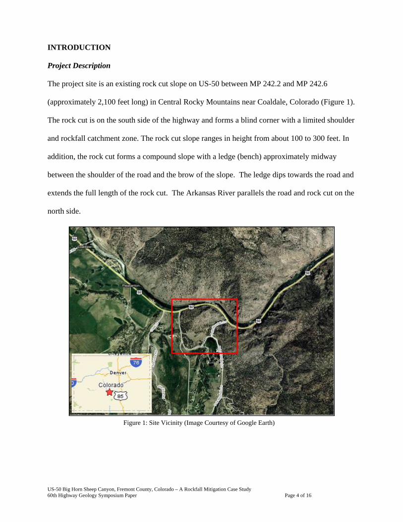
INTRODUCTION
Project Description
The project site is an existing rock cut slope on US-50 between MP 242.2 and MP 242.6
(approximately 2,100 feet long) in Central Rocky Mountains near Coaldale, Colorado (Figure 1).
The rock cut is on the south side of the highway and forms a blind corner with a limited shoulder
and rockfall catchment zone. The rock cut slope ranges in height from about 100 to 300 feet. In
addition, the rock cut forms a compound slope with a ledge (bench) approximately midway
between the shoulder of the road and the brow of the slope. The ledge dips towards the road and
extends the full length of the rock cut. The Arkansas River parallels the road and rock cut on the
north side.
Figure 1: Site Vicinity (Image Courtesy of Google Earth)
US-50 Big Horn Sheep Canyon, Fremont County, Colorado – A Rockfall Mitigation Case Study 60th Highway Geology Symposium Paper Page 4 of 16

Local Geology
Along this cut slope section, US-50 exposes Precambrian granodiorite. The regional geological
map states that the main body of the granodiorite is characterized as pinkish-gray, massive to
foliated, medium to coarse grained hornblende or biotite granodiorite. In localized areas, the
granodiorite is altered to granitic gneiss (Scott et al, 1979). During our field investigation, we
observed granitic gneiss with some localized areas of schist. The rock cut slope ranges in height
from about 100 to 300 feet. The rock slope dips to the north at angles ranging from 60 to 90
degrees and overhanging in some locations. In addition, the rock cut forms a compound slope
with a ledge (bench) approximately midway between the shoulder of the road and the brow of the
slope. This area is known as Gobbler’s Knob (Figure 2).
Design Challenges
Figure 2: Aerial Photograph of Cut Slope (Provided By CDOT)
In general, the overall rock
quality is good and
stabilization design was limited
to isolated areas of rock fall or
specific rock blocks.
Challenges were present with
developing a design to satisfy
the road and environmental
conditions. The roadway
consists of two 12-foot wide lanes and minimal shoulders of less than six feet. The limited space
reduced the potential for large crane support for rock anchoring. The limited road width and the
height of the slope limited the potential design for stabilization of blocks on the upper section of
US-50 Big Horn Sheep Canyon, Fremont County, Colorado – A Rockfall Mitigation Case Study 60th Highway Geology Symposium Paper Page 5 of 16
the slope. Additionally, the proximity of the Arkansas River limited the design and
recommendations for extensive scaling or blasting as part of the stabilization.
INVESTIGATION OVERVIEW
Rock Slope Mapping
As part of our field reconnaissance at rock cut slope locations, we completed detailed geological
and geomechanical mapping (Figure 3). Much of the information collected during our outcrop
mapping activities is attendant to the condition of discontinuities within the exposed rock masses
including discontinuity information such as dip,
dip direction, joint roughness and weathering
characteristics. General rock mass information
was collected to assess the quality of the rock
mass and estimate the rock quality designation
(RQD), Rock Mass Rating (Bieniawski, 1989)
and Geological Strength Index (Hoek, 1997).
Because of the height and inclination of the
existing rock cut slopes, much of our field
mapping was completed using mountaineering
(climbing and rappelling) techniques (Figure 3).
The rock slope mapping was completed along
the road level, along the mid-height bench and in vertical traverses spaced across the cut slope.
We focused three of the vertical traverses on specific large blocks we observed during our
preliminary field visit. Two large blocks start at the bench height and extend 40 to 60 feet down
Figure 3: Rock Slope Mapping using Mountaineering Techniques
US-50 Big Horn Sheep Canyon, Fremont County, Colorado – A Rockfall Mitigation Case Study 60th Highway Geology Symposium Paper Page 6 of 16

towards the road (Figures 4 and 5). There are tension fractures present behind these large blocks
indicating previous movement.
Figure 4: Rock Block 1 – Area of Concern Figure 5: Rock Block 2 – Area of Concern
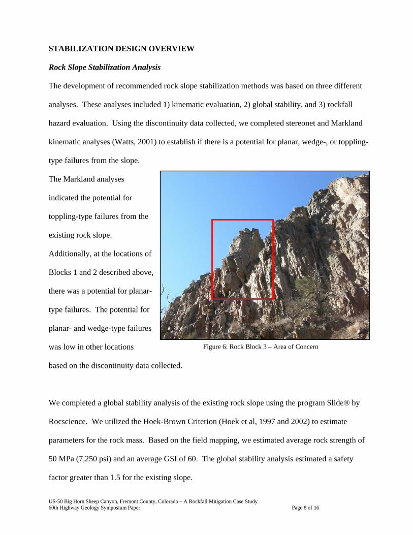
The third block is on the eastern end of the cut slope near the top of the slope approximately 300
feet above the road (Figure 6). Tension fractures are present along the side and base of this large
block.
US-50 Big Horn Sheep Canyon, Fremont County, Colorado – A Rockfall Mitigation Case Study 60th Highway Geology Symposium Paper Page 7 of 16
STABILIZATION DESIGN OVERVIEW
Rock Slope Stabilization Analysis
The development of recommended rock slope stabilization methods was based on three different
analyses. These analyses included 1) kinematic evaluation, 2) global stability, and 3) rockfall
hazard evaluation. Using the discontinuity data collected, we completed stereonet and Markland
kinematic analyses (Watts, 2001) to establish if there is a potential for planar, wedge-, or toppling-
type failures from the slope.
The Markland analyses
indicated the potential for
toppling-type failures from the
existing rock slope.
Additionally, at the locations of
Blocks 1 and 2 described above,
there was a potential for planar-
type failures. The potential for
planar- and wedge-type failures
was low in other locations
based on the discontinuity data collected.
Figure 6: Rock Block 3 – Area of Concern
We completed a global stability analysis of the existing rock slope using the program Slide® by
Rocscience. We utilized the Hoek-Brown Criterion (Hoek et al, 1997 and 2002) to estimate
parameters for the rock mass. Based on the field mapping, we estimated average rock strength of
50 MPa (7,250 psi) and an average GSI of 60. The global stability analysis estimated a safety
factor greater than 1.5 for the existing slope.
US-50 Big Horn Sheep Canyon, Fremont County, Colorado – A Rockfall Mitigation Case Study 60th Highway Geology Symposium Paper Page 8 of 16
The slope stability of Block 1 and Block 2 was evaluated as planar failures from the slope. We
assumed cohesion equal to zero because of the presence of tension cracks indicates that
movement has occurred. We assumed a factor of safety of 1.0 for our analyses and applied a
rock anchor force to achieve a factor of safety of 1.5. We completed hand calculations on the
blocks and checked the calculations using the computer program RocPlane V2® by Rocscience.
Block 1 and Block 2 are located below the mid-height bench. The slide plane of the blocks is
irregular and stepped from vertical to dipping towards the roadway at 55 to 65 degrees. To
complete the stability analyses, we assumed a uniform slide plane at the angle observed during
the field investigation. Based on our analyses for Blocks 1 and 2, we estimated that 15 to 20
25,000 pound tensioned rock anchors are required to achieve a factor of safety of greater than
1.5.
Stabilization Recommendations
Based on our analyses and field observations, we recommended stabilization methods for areas
and potentially unstable blocks on the rock slope. Based on existing stationing along the roadway,
the location of areas of concern and blocks were recorded and photographs were taken for figures
and design specifications. Various potentially unstable rock blocks were observed along the
length of the slope. Recommendations for the blocks included scaling and removal of the blocks
if feasible and stabilization with rock anchors in scaling was not feasible.
Along the western end of the rock slope, chutes and gullies that extended to the road elevation
were present with extensive loose rock. Stabilization recommendations for the chute and gullies
included wire mesh drape rockfall system and a modified wire mesh drape system. The modified
US-50 Big Horn Sheep Canyon, Fremont County, Colorado – A Rockfall Mitigation Case Study 60th Highway Geology Symposium Paper Page 9 of 16
system included anchors and cables at the top of the system to hold the top of the drape three to
four feet above the slope to allow rockfall to roll under the drape and be contained in the ditch.
Additionally, areas of highly fractured rock and blast damaged rock along the western end were
recommended to be mitigated with a wire mesh drape system.
Along the eastern end of the rock slope, the mid-height bench slopes towards the roadway.
Scaling was recommended along the mid-height bench to reduce the potential for rockfall. For the
three large blocks, we provided a recommendation for trim blasting to remove the unstable blocks.
Because of the proximity of the Arkansas River, this option was not feasible. Based on the
location and height on the slope of Block 3, stabilization or removal was not a feasible option. For
Block 3, crack meter telemetry was recommended to monitor potential movement of the block on
the rock slope.
Design and Construction Drawings and Specifications
Design and construction drawing specifications were prepared for the slope stabilization. The
construction drawings package contained overview photographs of the slope with areas requiring
stabilization highlighted (Figure 7). The photographs provided the contractor with a general
picture and stationing of where the various stabilization methods would be installed. Details on
the drawings summarized the rock anchor locations, quantities, geometries, loading requirements
and testing requirements. Additionally, details summarized the wire mesh drape rockfall system
installation specifications, wire mesh anchor installation, and approximate wire mesh quantities.
US-50 Big Horn Sheep Canyon, Fremont County, Colorado – A Rockfall Mitigation Case Study 60th Highway Geology Symposium Paper Page 10 of 16

Figure 7: Typical Construction Plans Slope Overview Sheet
CONSTRUCTION OVERVIEW
Construction began in September 2008 at the close of summer to avoid the heavy use period of the
Arkansas River. Slope stabilization was performed by AIS Construction. As described above,
stabilization included slope scaling in select areas, wire mesh and modified wire mesh installation,
rock anchor installation, crack telemetry installation.
Slope stabilization included environmental and technical construction challenges to the contractor.
Slope scaling was closely monitored and a wire mesh was hung from a crane to reduce the
potential for rockfall into the adjacent Arkansas River. To allow for traffic flow to continue, the
road had to be cleared of debris and field work stopped on 20 to 30 minute intervals. Weather
became a challenge as construction pushed into the late fall season in the Central Rocky
Mountains. Because of safety concerns, icy roads often slowed construction. In addition, the
US-50 Big Horn Sheep Canyon, Fremont County, Colorado – A Rockfall Mitigation Case Study 60th Highway Geology Symposium Paper Page 11 of 16

steep inclination and height of the rock slope provided technical challenges. Stabilization efforts
were completed with rope
access or from a basket on the
crane. Wire mesh placement
was completed with the
assistance of a helicopter
(Figure 8).
Slope stabilization progressed in
phases. Phase 1 was slope
scaling. Slope scaling was
completed in specific areas of
the slope and not the entire slope. Scaling was primarily completed on the western end of the rock
slope where gullies were present and where more loose rock and blast damage was observed.
Figure 8: Wire Mesh Installation with Helicopter Support
Figure 9: Wire Mesh Anchor Installation
Phases 2 and 3 included wire
mesh installation. During
Phase 2, anchors to suspend the
wire mesh were installed on
the slope. Anchors were
primarily installed using hand
drilling methods with the
contractor on rope access
(Figure 9). Two types of
wire
US-50 Big Horn Sheep Canyon, Fremont County, Colorado – A Rockfall Mitigation Case Study 60th Highway Geology Symposium Paper Page 12 of 16

mesh were installed to reduce rockfall onto the
roadway. The standard wire mesh drape
rockfall system was installed over areas with
rockfall potential (Figure 10). A modified wire
mesh drape rockfall system was installed in
gullies and areas where rockfall may occur
further up the slope. The m
included a
odified system
the top of the
e three to four
kfall to roll
(Figure 11).
wire mesh
s in Colorado
nchors and cables at
stem to hold the top of the drap
o allow roc
e contained
d
cation
e unstable rock blocks
identified during our field
mapping and analyses. Rock
anchors were installed from a
basket supported by the crane; also by a drill rig installed on the boom of the crane with the driller
sy
feet above the slope t
under the drape and b
CDOT has utilized the modifie
drape system in various lo
with success is containing
rockfall.
Phase 4 of the slope
stabilization was the
installation of rock anchors in
Figure 10: Installed Wire Mesh Drape Rockfall
th
Figure 11: Modified Wire Mesh Drape Rockfall System
US-50 Big Horn Sheep Canyon, Fremont County, Colorado – A Rockfall Mitigation Case Study 60th Highway Geology Symposium Paper Page 13 of 16

supported with ropes using mountaineering techniques. Rock anchors installed and tensioned
25,000 pounds. Lengths ranged from 10 to 20 feet.
For Phase 5, telemetry was installed on Block 3 to
Based on the location and height on the slope of Blo
feasible option. In a joint effort with CDOT
various locations along the tension crack behind
Block 3 (Figure 12). CDOT and Kleinfelder used
mountaineering techniques (rappelling and
climbing) to set-up at the desired locations. Hand
drills were employed to install the anchors for the
crack meters across the tension crack (Figure 13).
The crack meters are connected to a remote power
source and can be monitored remotely. With real-
time monitoring, the crack meters will detect the
to
remotely monitor movement of the block.
ck 3, stabilization or removal was not a
and Kleinfelder, three crack meters were installed at
ightest movement in Block 3. If movement occurs,
smitted to CDOT who will be
able to close the road to protect the travelling public.
CONCLUSIONS
Figure 12: Location of Crack Meters on Block 3
sl
a signal will be tran
US-50 Big Horn Sheep Canyon, Fremont County, Colorado – A Rockfall Mitigation Case Study 60th Highway Geology Symposium Paper Page 14 of 16

The CDOT Rockfall Hazard
Classification System
identified a 2,100-foot long
slope along US-50 in Central
Colorado because of blind
corners, limited rockfall
catchment, high traffic
volumes, and multiple
objective hazards. Through
discussions with CDOT, geologic mapping of the rock slope, and stability analyses, Kleinfelder
provided a range of recommendations for stabilization and mitigation of rockfall hazards from the
rock slope. During construction, Kleinfelder worked closely with CDOT to monitor construction
and provide field engineering consultation where necessary.
Figure 13: Close-up of Crack Meter across Tension Crack on Block 3
REFERENCES
Bieniawski, Z.T. (1989). Engineering Rock Mass Classifications. New York: Wiley.
FHWA. (1998). Rock Slopes Reference Manual (FWHA-HI-99-007). Wyllie, D., and Mah, C.W.
Hoek, E., and Brown, E.T. (1997). “Practical Estimates of Rock Mass Strength.” International
Journal of Rock Mechanics and Mineral Sciences, Vol. 34, No. 8, pp. 1165-1186.
Hoek, E., Carranza-Torres, C. and Corkum, B. (2002). Hoek-Brown criterion – 2002 edition.
Proc. NARMS-TAC Conference, Toronto, 2002, 1, 267-273.
US-50 Big Horn Sheep Canyon, Fremont County, Colorado – A Rockfall Mitigation Case Study 60th Highway Geology Symposium Paper Page 15 of 16

US-50 Big Horn Sheep Canyon, Fremont County, Colorado – A Rockfall Mitigation Case Study 60th Highway Geology Symposium Paper Page 16 of 16
Rocplane Version 2.0 (2003). Stability Analysis Software for Translational Failures.
RocScience Inc. Toronto, Canada.
Slide Version 5.0 (2003). Stability Analysis Software for Soil and Rock Slopes. RocScience
Inc. Toronto, Canada.
Watts, C.F. (2001). Rockpack III, Slope Stability Computerized Analysis Package Reference
Manual, Radford University, 48pp. and Appendices.
Wyllie, Duncan, C., Mah, C.W. (2004). Rock Slope Engineering: Civil and Mining, 4th Edition,
Spon Press, pp. 245-275