urbman-note plnng
DESCRIPTION
Urban Environmental Design Manual Horsley-Witten Group 90 Route 6A Sandwich, MA 02563 (508)833-6600 www.horsleywitten.com Richard Claytor - Principal Author Nate Kelly January 2005 Project Director: Scott Millar, Chief Sustainable Watersheds Office Rhode Island Department of Environmental Management Rhode Island Department of Environmental Management Thanks to: Dear Rhode Islander:TRANSCRIPT

Urban Environmental Design Manual

The Urban Environmental Design Manual
January 2005
Project Director: Scott Millar, Chief
Sustainable Watersheds OfficeRhode Island Department of Environmental Management
Dodson Associates, Ltd.463 Main Street
Ashfield, MA 01330(413)628-4496
www.dodsonassociates.comPeter Flinker, ASLA - Project Manager &
Principal AuthorHarry L. Dodson, ASLA
Sarah la CourHillary Blanchette
Kevin Wilson - Illustrator
Horsley-Witten Group90 Route 6A
Sandwich, MA 02563(508)833-6600
www.horsleywitten.comRichard Claytor - Principal Author
Nate Kelly
Rhode Island Department of Environmental Management
Acknowledgements
Thanks to:
Peter Hanlon, DEM Sustainable Watersheds; Eric Beck, Carol Murphy, Jim Riordan, and Chris Turner, DEM Water Resources; Mickie Musselman, DEM Planning and Policy; Frank Gally, Joseph Martella, & Kelly Owens, DEM Waste Management; George Johnson, Assistant Chief, RI Statewide Planning Program; Derwent Riding, Ronnie Sirota, Blanche Higgins & Nancy Hess, RI Statewide Planning Program; Beth Collins, RI Economic Policy Council; Michael Cassidy & Karen Godin, Pawtucket; Tom Kravitz, Burrillville; Roberta Groch, Providence; Merrick Cook, Central Falls; Keith Byrnes, Woonsocket; Amrita Hill, Smithfield, Katia Balassiano, Cumberland; Rosemary Monahan, Smart Growth Coordinator, EPA New England; Margherita Pryor, EPA New England; Danielle Fulgini, EPA New England; Michael Creasey & Hal Welch, John H. Chafee Blackstone River Valley National Heritage Corridor Commission; Jane Sherman, Woonasquatucket River Watershed Council; Joe Newsome, South Providence Development Corporation; Sheila Brush, Grow Smart RI; Tammy Gilpatick, Blackstone River Watershed Council; Doug Brown, Durkee Brown Architects; Johanna Hunter, EPA River Navigator; John Gregory, Northern RI Chamber of Commerce; Barry Preston, Armory Revival Company; Patty Gambarini, Southern RI Conservation District; Paul Pawlowski, Pawlowski Associates, Inc., Eric Scherer & Andrew Lipsky, USDA NRCS

Dear Rhode Islander:
There is an increasing interest in redirecting development into our urban areas. This “smart growth” movement is not only good for the environment by taking development pressure off our farms and forests but makes good economic sense since it more efficiently takes advantage of the tremendous public investment in infrastructure and is restoring abandoned properties to the tax rolls. The revitalization of our urban neighborhoods also adds immeasurably to our quality of life. Although redevelopment of our urban communities is desirable, it may further impact natural systems that are already impaired. The purpose of the Urban Environmental Design Manual is to encourage environmentally sound urban revitalization and infill development by providing guidance to local officials and the development community to demonstrate how smart growth design principles can be integrated with environmental protection and restoration. There is a direct correlation between land use patterns, the way a site is developed and environmental degradation. Poorly planned growth has been well documented to have devastating impacts to natural, cultural and recreational resources. However, well-planned growth using flexible land use techniques with attention to good site design and development practices can prevent subsequent and restore existing impacts to the environment and community character. The manual offers alternative and cost effective techniques that can assist with the challenge of redeveloping urban sites.
Thanks to the financial support from Environmental Protection Agency and the John H. Chafee Blackstone River Valley National Heritage Corridor Commission, RIDEM in partnership with a broad based advisory committee obtained the professional services of nationally recognized planning, design and environmental management experts Dodson Associates and Horsley Witten Group to prepare this manual. The recommendations contained in this manual reflect the hard work and dedication of the consultants, as well as the advisory committee who volunteered their time to help make this project a success. We at RIDEM take great pride in being able to provide Rhode Island Communities the assistance they need to plan for growth while protecting, preserving and restoring the environment.

Urban Environmental Design Manual 1
Table of ContentsI. Chapter 1 – Introduction to the Project and Principles of Urban Environmental Design
Introduction ............................................................................ 1Project Overview .................................................................... 3Urban Design Issues and Redevelopment Principles.............. 6
II. Case Studies in Urban Environmental DesignOverview ................................................................................ 10Stillwater Mill ........................................................................ 13Rau Fastener ........................................................................... 23Tidewater................................................................................. 33Central Falls .......................................................................... 43Best Management Practices as Urban Design Elements ....... 53
III. Best Management Practices for Urban SitesIntroduction ............................................................................ 55Rain Barrels and Cisterns ....................................................... 57Stormwater Planters ............................................................... 60Permeable Paving.................................................................... 63Open Channels ....................................................................... 67Stream Daylighting ................................................................ 74Vegetated Buffers .................................................................. 76Stormwater Wetlands ............................................................ 80Bioretention............................................................................ 85Green Rooftop Systems ....................................................... 90
IV. Appendix - Development Criteria (Separate Document)Introduction ............................................................................ 2Buffer Zones/Habitat Protection or Restoration and On-Site Wetlands ................................................................................. 3Preservation of Historic Places ............................................... 9Development in a Floodplain.................................................. 10Pedestrian Access, Parking and Intermodal Transportation ... 15Landscape Standards ............................................................. 23Mixed Use Development ....................................................... 27Open Space ............................................................................ 31Third Party Review Fees ....................................................... 36Adequate Public Facilities ..................................................... 41Stormwater Management, Impervious Surface Reduction, and Erosion and Sediment Control ......................................... 44Enabling Brownfield Redevelopment .................................... 56Hazardous Materials Storage and Handling .......................... 59
Urban Environmental Design Manual 1
Introduction
The purpose of this manual is to show how “smart growth” design principles can be united with best management practices for stormwater to create communities that are more livable, more successful economically and more environmentally sustainable. This integration of ideas and techniques offers striking opportunities to turn difficult sites into growth centers that help revitalize surrounding neighborhoods. This approach offers immense advantages in allowing city officials, residents, and developers to work together to coordinate public and private investment, creating a synergy that produces the greatest potential benefit to all. By building more efficiently, learning from the past about how to make more livable communities and channeling the resulting savings into additional quality of life amenities, developers and municipalities can leverage the collective investment they would have to make anyway to achieve a whole that is truly greater than the sum of its parts.
The diverse movements in planning, design and engineering that are integrated in this report have been developed by people all over the country over the last twenty years. For example, smart growth has emerged as a common theme in regional planning, largely in response to the inefficiencies and excesses of suburban sprawl. In architecture, the principles of New Urbanism show how to rebuild urban neighborhoods and redevelop suburbs to
be more livable and pedestrian-friendly. In environmental planning, Sustainable Design is the watchword, focusing on development that uses resources more efficiently and reduces energy requirements. And in civil engineering, the design of stormwater systems has evolved from costly “end of pipe” systems to “low impact development” techniques that return stormwater to the ground close to the source and maintain existing hydrology.
Planners and professionals in each of these disciplines are beginning to think about how these techniques can be united into a comprehensive approach. This process, of which this manual is one example, is driven partly by the necessity of stretching state and municipal budgets to do more with less. It has received a considerable boost from the leadership of the US Environmental Protection Agency, which has developed an extensive program on the subject of smart growth and environmental restoration (www.epa.gov/livability).
Along with this carrot of information and outreach, EPA has a stick – the Phase II Stormwater Regulations. Growing out of 1987 amendments to the Federal Clean Water Act, Phase I of the National Pollution Discharge Elimination System (NPDES) went into effect in 1990. Phase I required NPDES permits for stormwater discharges from municipal separate storm sewer systems (MS4s) in places or counties with populations over 100,000, and for construction projects that disturb more than five acres. In 1999, EPA published final rules for Storm Water Phase II. Phase II requires NPDES permits for stormwater discharges from small MS4s and construction activities that disturb between 1 and 5 acres. In practice, this means that most communities and development projects in Rhode Island are subject to the Phase II regulations. As part of complying with the requirements of Phase II, EPA requires communities to
Chapter 1 – Introduction to the Project and Principles of Urban Environmental Design
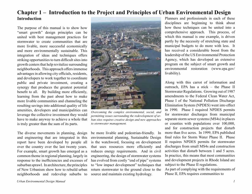
Overcoming the complex environmental, social, and permitting issues surrounding the redevelopment of ur-ban sites requires creative design and new approaches to stormwater management.

Urban Environmental Design Manual2 Urban Environmental Design Manual 3
establish a stormwater management program. Such a program must include six minimum control measures:
1. Public education and outreach. 2. Public participation/involvement.3. Illicit discharge detection and
elimination.4. Construction site runoff control.5. Post construction runoff control.6. Pollution prevention/good housekeeping.
As described in a new publication, “Protecting Water Resources with Smart Growth,” a community’s smart growth plans can help fulfill many of these minimum control measures (www.epa.gov/livability/water_resource.htm). The theme of that publication is that reducing the impact of stormwater runoff is as much a function of the overall pattern of land use and the layout of development projects as it is of specific engineering techniques to treat water “at the end of the pipe.” While it was developed independently, the Urban Environmental Design Manual illustrates how this approach works. Using real sites in urban areas, it details how a combination of smart growth master planning and creative stormwater design can overcome common environmental road blocks and planning complexities.
While the USEPA has led nationally in demonstrating the application of smart
growth principles to environmental planning and design, the citizens and public officials of Rhode Island have not been idle in pursuing progressive approaches to planning – in fact, Rhode Island has been a leader in promoting comprehensive planning and creative zoning. For example, the Governor’s Growth Planning Council, established in 2000 by an Executive Order from Governor Lincoln Almond, was charged with finding a way to balance Rhode Island’s needs for economic and residential development with those for environmental preservation (www.planning.state.ri.us/gpc/default.htm). The order noted that “continued growth of Rhode Island will dramatically
change the face of the state in the future, and the integration of economic development, environmental protection and preservation, and community needs is essential to maintain and enhance the quality of life for future generations.”
The Council’s mission includes a broad interagency effort, designed to:
• examine the economic, environmental, and social impacts of current development patterns in the state;
• inventory existing State programs, policies, and expenditures to evaluate
While smart growth often points to sites with access to roads and services as the most appropriate for develop-ment, this can increase pressure on natural systems that are already stressed. Creative approaches to stormwater engineering can protect riparian corridors while adding amenities that increase the quality of life for residents.

Urban Environmental Design Manual2 Urban Environmental Design Manual 3
their effect on sustainable development and the preservation and enhancement of environmental quality and resources;
• recommend ways of encouraging growth in economically and environmentally sound locations;
• serve in an advisory capacity to local communities in the development of their land use plans;
• and recommend any changes in State and federal law or regulations.
In 2002, the Council published a report that outlines an ambitious program with a simple theme: “Growth Centers: Recommendations for Encouraging Growth and Investment in Economically and Environmentally Sound Locations in Rhode Island.” The Growth Centers concept is designed to focus planning and public investment on areas that each community identifies as the most appropriate for growth. Growth Centers are defined as “dynamic and efficient centers for development that have a core of commercial and community services, residential development, and natural and built landmarks and boundaries that provide a sense of place.” Incorporated into the State Guide Plan and the Handbook on Comprehensive Planning, the Growth Centers idea will guide planning and investment at both the local and regional level. A major road block to implementing the Growth Centers concept is that fact that in
many urban areas where they make the most sense, the development of growth centers is hampered by issues of access and parking, decaying buildings and infrastructure, and industrial contamination. The complications of planning and permitting, combined with environmental hazards, can make it seem
easier to develop suburban greenfields than to take on urban brownfields. The purpose of this manual is to show how these road blocks can be overcome with the creative integration of planning, public participation, and environmental engineering -- turning liabilities into opportunities for economic growth and revitalization at the heart of our communities.
Project Overview
This Urban Environmental Design Manual is intended to promote environmentally responsible urban revitalization and infill development by providing guidance to local officials, the development industry, community groups and the public. This guidance is designed to identify techniques to address issues of environmental protection and sustainable development in an urban setting and to facilitate brownfields redevelopment through illustrated design scenarios and model development standards. These materials show communities how to promote sustainable economic development and enhanced quality of life while protecting the character of urban neighborhoods and revitalizing neglected areas.
As described above, the Urban Environmental Design Manual is connected with a broader statewide effort to prevent urban sprawl and to direct development towards existing villages and urban centers to protect sensitive
The Growth Centers approach is designed to help focus public and private investment in the locations where it makes the most sense. This is exemplified by Waterplace Park in Providence, the centerpiece of an extraordinary urban revival.

Urban Environmental Design Manual4 Urban Environmental Design Manual 5
natural resources and to encourage sustainable development. The project was designed to develop guidance for these urban construction and renovation projects so that, to the extent possible, the development can maintain and restore the natural environment. The project had five key elements:
• Formation of a broad-based Advisory Committee to identify common issues and concerns of potential stakeholders in urban development and redevelopment projects.
• Creation of planning and design scenarios to serve as case studies illustrating recommended techniques for combining stormwater management with urban design.
• Recommended best management practices for stormwater management on urban sites.
• Model zoning ordinance language, to help communities implement the concepts illustrated in the manual.
• Development of training materials and educational workshops.
The Advisory Committee was composed of local planners, representatives of state and federal agencies and non-profit groups, and independent professionals. The committee met regularly over the course of the project to help the consultant team identify key issues to be addressed, select practices to be explored, nominate potential case study
• Sustainable landscaping standards.• Preserving public health; dealing
with hazardous wastes and other contamination.
• Climate and air quality issues.• Wastewater management.
With these key issues identified, the project team worked with the Advisory Committee to identify a series of case study sites that would illustrate real-world solutions to the problems of redeveloping urban sites. In order to select sites that represented the full range of issues and types, a matrix was developed that compared each potential site against a range of types, including brownfields, greyfields, vacant/abandoned property, village, and urban neighborhood. Other criteria incorporated into the matrix included the mix of uses, historic preservation, riparian zone preservation/restoration and community support. Using the matrix, the advisory committee selected the four sites that are described in detail in Chapter 2. Located in Providence, Pawtucket, Central Falls and Burrillville, the case studies offer a broad range of problems and potential solutions:
• Revitalization of a mill complex in a rural village.
• Redevelopment of an urban mill complex.
• Restoration of a riverfront brownfield for economic development.
• Revitalization of an urban neighborhood.
sites and review the design scenarios and recommendations. Their first task was to list the issues that planners, developers, and reviewing agencies struggle with on a day to day basis. These included both urban design issues and environmental issues, which became the touchstones for developing case study scenarios and best management practices described in this report:
Urban Design Issues:
• Single use vs. mixed use development.• Historic preservation and protection of
neighborhoods.• Traffic and transportation, transit-oriented
design.• Site access and parking.• Open space protection.• Planning for public access and recreation.• Gentrification.• Financing and tax strategies.• Accommodating siting for industrial
facilities.
Environmental issues:
• Planning strategies for environmental protection and restoration.
• Conservation and restoration of natural habitat and healthy riparian ecosystems.
• Controlling stormwater runoff; low impact design techniques.
• Green architecture techniques.• Green parking lots.

Urban Environmental Design Manual4 Urban Environmental Design Manual 5
As part of the four design scenarios, detailed best management practices were developed to illustrate the process of selecting and designing stormwater practices tailored to the site and the urban design goals of each project. The factors considered in the selection process include land use, physical constraints, watershed context, required capacity, pollutant removal needs, environmental benefits, and maintenance issues. As described in detail in Chapter 2, these practices illustrate how local planners and developers can select from the many options being pursued throughout the country those that will be most useful to solving specific local problems.
The final element of the Urban Environmental Design Project was model zoning language designed to bridge the gap between creative planning and design and real-world implementation of the recommended tools and techniques. Rather than providing a set of complete ordinances, these materials have been organized as a set of development standards and review criteria, which can be incorporated into local ordinances and review procedures according to the specific need of individual cities and towns. These development standards are intended to provide detailed information that communities, developers, engineers and planners can use in designing and reviewing redevelopment
projects. Standards are provided for buffers, preservation of historic resources, parking/intermodal transportation, landscaping, mixed use development, open space preservation, third party review fees, adequate public facilities, stormwater management/erosion control, enabling brownfield development, and storage of hazardous materials. These considerations were developed over the course of the project through discussions with the Design Manual Committee and represent a mix of legal, planning, aesthetic and engineering considerations. Because of the resulting length and amount detail, they are included as a stand-along appendix to this manual.
The sites selected as case studies for the Urban Environmental Design Manual were chosen to represent a range of situations faced by communities across the state. They range from the Rau Fastener complex in the center of Providence (left) to the Stillwater Mill in rural Burrillville (right). They share similar complexities in terms of brown-field remediation, environmental permitting, economic development and neighborhood concerns.

Urban Environmental Design Manual6 Urban Environmental Design Manual 7
1. Mixed-Use Development: Provide a mix of residential, commercial, and business uses wherever possible.
Urban neighborhoods and downtowns with long-term success almost always include a flexible mix of land uses and available spaces that can adapt to changing market demands. Often this means changing regulations to promote mixed-use development. It also means encouraging the concept of flexible design of buildings that allows for many different kinds of tenants over the lifetime of a structure. This is the opposite of recent trends in strip commercial architecture, which is driven by corporate chains, each of which has a standard building design which often needs to be torn down to accommodate a change in use or tenants.
2. Contextual Design: Reflect the surrounding natural and cultural context in the design of each project.
The historic pattern and density of urban neighborhoods and village centers was the result of centuries of trial and error, when limitations of energy and building techniques forced a reliance on simple, sustainable materials and technologies. By starting with the existing patterns of streets and land uses as a template for new development, designers incorporate the social and environmental benefits embedded in those patterns.
On a practical level, the historic design of streets and density of structures in the neighborhood surrounding a redevelopment site often embody the sense of place of that particular community. By building on that sense of place and maintaining the original intensity of land uses, developers can create the kind of visual character that attracts tenants and builds value in the property. Cities and towns should avoid the gradual trend towards suburbanization that can spoil the efficient functioning and visual distinctiveness of the traditional downtown.
3. Transit-Oriented Design: Minimize the need for private automobiles and encourage the use of public transportation.
Even small projects can incorporate planning for how users can take advantage of public transportation. This can be as simple as a bus stop or pedestrian overpass to nearby transit station, park and ride lots and van pool programs. Larger projects can work with local government to secure grants to build facilities that serve the surrounding area as well as the immediate development site. These add value to the project both directly and indirectly, by creating demand for service businesses catering to commuters.
4. Shared Site Access: Promote shared curb cuts, driveways, and access roads by planning that includes
Urban Design Issues and Redevelopment Principles
Over the course of the project, the Advisory Committee and the project team developed a list of common problems and issues in urban environmental design that served as the touchstone for the other elements of the project. These issues, ranging from selecting appropriate land uses and density of development to stormwater management, include many aspects of urban design that planners and regulators face on a daily basis. They also represent key stumbling blocks to a more sustainable approach to development that many communities have said, through their comprehensive plans, that they wish to achieve, but which is often hard to implement because of outdated regulations and development practices.
These issues were one factor in selecting the case study sites, and were returned to again and again as design alternatives were evaluated. In each case, specific solutions to these general issues were developed for each site that reflected its unique problems and opportunities. By looking at the case studies as a whole, however, certain common principles emerged that can serve as a general guide to development and redevelopment of urban sites. The following principles start with recommendations for landuse and design and conclude with principles for stormwater management and environmental engineering:

Urban Environmental Design Manual6 Urban Environmental Design Manual 7
multiple structures and surrounding parcels.
Many planned development projects provide for efficient access by providing a single access road and shared parking areas for multiple structures. This approach can be extended by including surrounding parcels in master planning for a redevelopment site. This allows project planners to identify opportunities to connect alleys and access roads across lot lines, reduce unnecessary curb cuts, and provide continuous pedestrian routes that encourage walking. Working together on a district or neighborhood level can make access clearer, more efficient and user friendly, while reducing the need for pavement throughout the area.
5. Flexible Parking Standards: Provide enough parking for the proposed uses, but take into account creative strategies to reduce demand and use space efficiently.
Commercial zoning often specifies parking to meet the greatest possible demand, and treats every site as if it were a suburban shopping mall. Urban sites, however, vary tremendously in the needed amount of parking, depending on the proposed use and location and context of the site. It may make more sense to invest in amenities that encourage pedestrians and bicyclists and enhance connections to nearby transit stations than to build unnecessary
surface lots. Mixed-uses lend themselves to shared parking, with a project’s residents using parking at night which during the day is filled with office workers and customers. Phased development of parking can allow new lots to be constructed to meet demand, rather than building everything at once. Provision of gravel or grass-surfaced overflow lots can also meet seasonal demand for parking while reducing impervious surface area. Finally, parking structures should be considered, where feasible, to minimize the impact of stormwater runoff.
6. Public access and Recreation: Provide permanent public access and recreational opportunities as part of the development master plan.
Creation of continuous, publicly-accessible waterfront promenades and river greenways is a common goal for cities and towns throughout the country. Developers are starting to realize that helping to build these systems as part of a project builds market identity and helps to create something much more valuable than anything that could be done as part of a single project. Like anything else, implementation requires both carrots, in the form of planning help and public support, and sticks, such as regulatory requirements to preserve public access. Site-specific recreational amenities, such as parks, ball fields and boating centers can likewise serve both the residents of a project and the general public, supporting
concessions and recreational programming that benefits everybody.
7. Open Space Protection: Preserve open space areas containing significant natural and cultural resources.
While the perceived short-term advantages of clearing all existing features from a site to prepare for redevelopment often win out, communities and developers are beginning to recognize the value of preserving the best features of a site and designing around them. This can preserve the value of natural areas and historic sites, not just for the general public, but as something which adds value to the new development. By starting the planning process with a careful site analysis, these features can be identified and their potential role in the project defined before they are lost. Since trees are sometimes the most significant natural feature on an urban site and adjacent city streets, they should be included in any study of open space resources. The Rhode Island Urban and Community Forest Program provides guidelines for planning and conservation of urban trees.
8. Stormwater Parks: Leverage stormwater management improvements to build public amenities.
The investment that corporations and municipalities must make to meet the requirements of state and federal stormwater

Urban Environmental Design Manual8 Urban Environmental Design Manual 9
regulations can easily be leveraged to build new parks and amenities that enhance the quality of life for residents and businesses. Rather than spending the money to build detention ponds sealed off behind chain link fences, coordinated planning for stormwater management, recreation sites and natural resource buffers can help create a continuous park system at the edge of every neighborhood and lining every river corridor.
9. Gentrification: Recognize and mitigate gentrification resulting from urban redevelopment.
Redevelopment of brownfields and revitalization of urban neighborhoods can result in the displacement of affordable housing and inexpensive business space. The creation of permanent, affordable housing should be part of every redevelopment project that includes housing. Small business can be encouraged with business incubators, shared community office and meeting space, and community technology and telecommuting centers.
10. Tax Policy and Public Investment:Leverage private investment through targeted public improvements and supportive tax policies. Both state and municipal governments can encourage private investment with targeted public improvements. Typically including
roads, sidewalks, parking lots and parks, these projects build tangible value in neighborhoods that encourages private investment in building renovations and new construction. The Rhode Island Growth Centers Initiative provides guidelines for communities in identifying growth centers and planning for public improvements.
Local, state and federal tax policies provide an important tool for encouraging private investment in neighborhood revitalization and affordable housing. The RI Historic Preservation Tax Credits and Mill Building Rehab Tax Credits are two examples.
11. Riparian Buffers and Natural Habitat:Preserve and restore natural habitat and healthy riparian ecosystems. A key objective for development and redevelopment involves the preservation and restoration of lands immediately adjacent to aquatic ecosystems. These systems are the most ecologically productive and offer the best opportunity to achieve the multiple objectives of preserving threatened and endangered species, reducing pollutant loading from urban runoff, maintaining stable stream banks, providing a corridor for species migration, and enhancing property values. Municipalities can provide a mix of regulations, guidelines and incentives for developers to maintain adequate buffers and natural areas and programs to control invasive
species once these natural areas have been retained.
12. Stormwater Management: Control stormwater runoff close to the source with low impact development techniques
A suite of methods and techniques exist that promote the diffusion of urban runoff at the source. These include site design alternatives that help to limit impervious surfaces; stormwater measures that promote filtering and infiltration, including water quality swales, bioretention, pervious pavements, and alternative infiltration practices; stormwater storage practices that promote recycling of rainfall including cisterns and rain barrels; and alternative vegetative roofing systems that provide rooftop storage and less runoff. All of these techniques will help maintain and/or reestablish a better long-term water balance to augment and sustain groundwater supplies for drinking water and preservation of wetland resources.
13. Green Architecture: Employ design techniques, materials, and life cycle planning that reduce energy requirements and promote sustainability. A variety of green building methods and operational considerations are now available to create more sustainable development and redevelopment projects. These include: green

Urban Environmental Design Manual8 Urban Environmental Design Manual 9
roof technologies, recycled building materials, energy saving designs that utilize passive and active solar radiation to lower heating and cooling costs, and storage of stormwater for reuse as irrigation water, non-potable water supplies and reduction of net runoff volume.
14. Green Roads and Parking Lots: Use materials and design standards that reduce impervious surfaces and pollutant load.
Several site design strategies exist that can help reduce the impacts from road and parking runoff, these include: narrower and shorter streets, smaller rights-of-way, smaller turn-arounds, open channel drainage design, smaller parking lots based on realistic parking demand data or shared parking, smaller parking stalls and drive aisles, use of infiltration practices for smaller drainage areas, and/or the use of permeable pavers for overflow parking areas. Collectively, these practices result in less runoff and reduced pollutant load delivery to receiving waters.
15. Sustainable Landscaping Standards:Promote use of species and planting techniques that reduce need for irrigation and support long-term sustainability.
There is a basic approach, known as ecological landscaping, that promotes native species over non-native species, especially those that are more drought tolerant, require fewer pesticides
and fertilizers and increase erosion protection. This approach replaces traditional turfgrass with a landscape of native trees, shrubs, and perennials that require less maintenance and less irrigation while providing wildlife habitat for birds, butterflies, and small mammals. The RI Wild Plant Society and URI’s Greenshare Program provide information on sustainable landscapes.
16. Environmental Site Assessment:Conduct an assessment of site constraints and opportunities at the outset of the redevelopment planning process::
Many older urban areas and land uses have contributed some level of contamination to soils and groundwater. Municipalities can require urban redevelopment projects to include a provision to conduct an environmental site assessment that identifies the basic site history, and maps existing resource constraints (floodplains, wetlands, streams, springs, natural area remnants, etc.). Where past site history suggests possible contamination, soil and groundwater testing is warranted.
17. Climate and Air Quality: Avoid materials and planning patterns that contribute to global warming, while encouraging techniques that provide natural cooling and air filtration as part of the project.
Redevelopment and infill projects can either contribute to the status quo, or incorporate design measures that contribute to a cumulative benefit in climate and air quality. Projects that incorporate green roofs, recycled materials, intermodal transportation design, permeable pavers, and similar elements will help reduce urban heat island effects, automobile induced air quality impacts and pollutant loading delivery to receiving waters.
18. Wastewater Management: Use planning and investment in wastewater systems to add value to urban neighborhoods and discourage suburban sprawl into sensitive areas. Wastewater infrastructure capacity is a scarce public resource, and a key determinant of growth. Guided by local Comprehensive Plans, the benefit of public investment should be maximized by ensuring appropriate density in serviced areas, while discouraging growth in unserviced areas. Reliance on individual wastewater systems can overburden coastal waters with nutrient loading and/or contaminate swimming and shellfish resource areas with bacteria. At the same time, communities need to balance effective wastewater treatment with maintenance of groundwater levels to preserve wetland resources and drinking water supplies. Municipalities on centralized sewer systems may need to augment groundwater recharge where wastewater is piped outside of a particular basin.

Urban Environmental Design Manual10 Urban Environmental Design Manual 11
Chapter 2 -- Case Studies in Urban Environmental DesignWhile the issues and recommended develop-ment principles described in the first chapter provide an overview of the shared wisdom on urban redevelopment and stormwater man-agement, it is sometimes hard to make the leap from theory to practical application of these principles. To help make this connec-tion, this manual includes four case studies: actual sites chosen to demonstrate how urban design principles can be combined with best management practices for stormwater in the redevelopment of brownfields and urban neighborhoods. The purpose of this approach is to show how these ideas play out in the real world, using a range of sites with which many people are familiar.
The four case study sites were selected with the help of the project advisory committee. The group provided a list of potential study sites, some of which have previously been the subject of extensive planning, while oth-ers have not. Each of these nominated sites was evaluated against the list of issues and design ideas identified earlier in the process. An evaluation matrix identified both the type of site (i.e., waterfront brownfield, historic village infill, urban neighborhood) as well as the type of development (mixed use, housing, industrial, etc). The matrix also evaluated the environmental context of each site, describing whether it was in a riparian corridor or flood zone, close to sensitive wetlands, or surround-ed by a residential neighborhood.
Using this approach, the advisory committee and the project team were able to winnow a list of suitable sites down to four which best represented a cross-section of locations and design challenges. Located across Northern Rhode Island, the sites range from central Providence to rural Harrisville, and collec-tively cover a range of urban design issues common to communities across the region.
The first site, known as the Stillwater Mill Complex, is found in the village of Harris-ville in the town of Burrillville. Surrounded by what is still a semi-rural landscape (photo at right), the village retains the compact, self-contained character established a century ago. After production of worsted cloth ceased in 1963, the site has had a variety of users, and today supports a mix of service, storage and repair operations -- but nothing on a scale that could take advantage of the site or the remain-ing mill buildings (right, below).
Recent efforts by the town planning depart-ment and the Burrillville Redevelopment Agency, however, have jump-started a pro-cess to redevelop the site as the active heart of the surrounding community. Of particular concern are issues of traffic and parking, and the potential impact of redevelopment on the Clear River, which provided the original water power for the site and flows right next to the mills. Plans call for a mixed use center that would be closely tied to the rest of the village with pedestrian paths and greenways.
Urban Environmental Design Manual10 Urban Environmental Design Manual 11
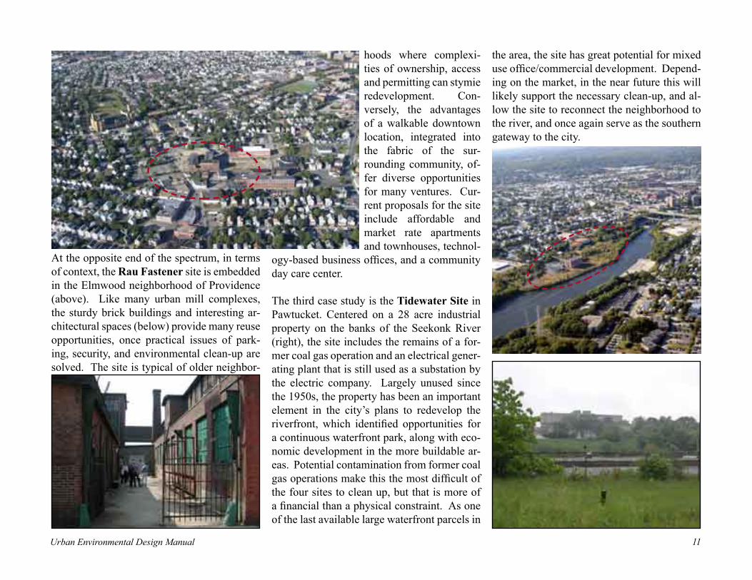
At the opposite end of the spectrum, in terms of context, the Rau Fastener site is embedded in the Elmwood neighborhood of Providence (above). Like many urban mill complexes, the sturdy brick buildings and interesting ar-chitectural spaces (below) provide many reuse opportunities, once practical issues of park-ing, security, and environmental clean-up are solved. The site is typical of older neighbor-
hoods where complexi-ties of ownership, access and permitting can stymie redevelopment. Con-versely, the advantages of a walkable downtown location, integrated into the fabric of the sur-rounding community, of-fer diverse opportunities for many ventures. Cur-rent proposals for the site include affordable and market rate apartments and townhouses, technol-
ogy-based business offices, and a community day care center.
The third case study is the Tidewater Site in Pawtucket. Centered on a 28 acre industrial property on the banks of the Seekonk River (right), the site includes the remains of a for-mer coal gas operation and an electrical gener-ating plant that is still used as a substation by the electric company. Largely unused since the 1950s, the property has been an important element in the city’s plans to redevelop the riverfront, which identified opportunities for a continuous waterfront park, along with eco-nomic development in the more buildable ar-eas. Potential contamination from former coal gas operations make this the most difficult of the four sites to clean up, but that is more of a financial than a physical constraint. As one of the last available large waterfront parcels in
the area, the site has great potential for mixed use office/commercial development. Depend-ing on the market, in the near future this will likely support the necessary clean-up, and al-low the site to reconnect the neighborhood to the river, and once again serve as the southern gateway to the city.
Urban Environmental Design Manual12 Urban Environmental Design Manual 13
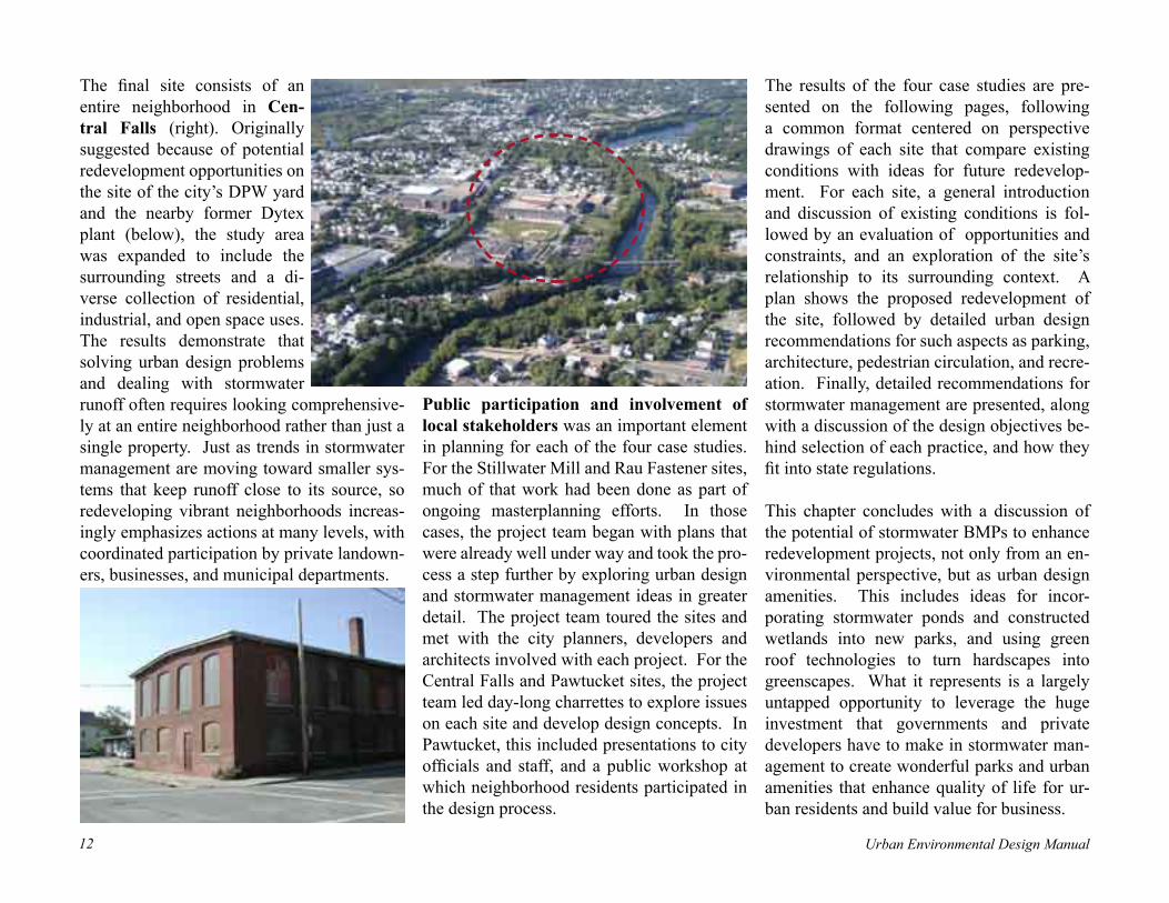
The final site consists of an entire neighborhood in Cen-tral Falls (right). Originally suggested because of potential redevelopment opportunities on the site of the city’s DPW yard and the nearby former Dytex plant (below), the study area was expanded to include the surrounding streets and a di-verse collection of residential, industrial, and open space uses. The results demonstrate that solving urban design problems and dealing with stormwater runoff often requires looking comprehensive-ly at an entire neighborhood rather than just a single property. Just as trends in stormwater management are moving toward smaller sys-tems that keep runoff close to its source, so redeveloping vibrant neighborhoods increas-ingly emphasizes actions at many levels, with coordinated participation by private landown-ers, businesses, and municipal departments.
Public participation and involvement of local stakeholders was an important element in planning for each of the four case studies. For the Stillwater Mill and Rau Fastener sites, much of that work had been done as part of ongoing masterplanning efforts. In those cases, the project team began with plans that were already well under way and took the pro-cess a step further by exploring urban design and stormwater management ideas in greater detail. The project team toured the sites and met with the city planners, developers and architects involved with each project. For the Central Falls and Pawtucket sites, the project team led day-long charrettes to explore issues on each site and develop design concepts. In Pawtucket, this included presentations to city officials and staff, and a public workshop at which neighborhood residents participated in the design process.
The results of the four case studies are pre-sented on the following pages, following a common format centered on perspective drawings of each site that compare existing conditions with ideas for future redevelop-ment. For each site, a general introduction and discussion of existing conditions is fol-lowed by an evaluation of opportunities and constraints, and an exploration of the site’s relationship to its surrounding context. A plan shows the proposed redevelopment of the site, followed by detailed urban design recommendations for such aspects as parking, architecture, pedestrian circulation, and recre-ation. Finally, detailed recommendations for stormwater management are presented, along with a discussion of the design objectives be-hind selection of each practice, and how they fit into state regulations.
This chapter concludes with a discussion of the potential of stormwater BMPs to enhance redevelopment projects, not only from an en-vironmental perspective, but as urban design amenities. This includes ideas for incor-porating stormwater ponds and constructed wetlands into new parks, and using green roof technologies to turn hardscapes into greenscapes. What it represents is a largely untapped opportunity to leverage the huge investment that governments and private developers have to make in stormwater man-agement to create wonderful parks and urban amenities that enhance quality of life for ur-ban residents and build value for business.

Urban Environmental Design Manual12 Urban Environmental Design Manual 13
Stillwater Mill -- Existing Conditions Before Redevelopment

Urban Environmental Design Manual14 Urban Environmental Design Manual 15
Stillwater Mill -- Introduction to the SiteThe study area has been in continuous use for almost 200 years, reaching its peak with the construction of the Stillwater Mill in 1911. Reported to be the first mill in the country constructed of reinforced concrete, it was the centerpiece of worsted cloth production until operations ended in 1963. Occupied by a va-riety of uses since then, the former mill and the surrounding lots included in the study area comprise some 20 different properties total-ling 21.7 acres. While some of the buildings have been torn down, those that remain are for the most part structurally sound. Current uses include a fitness center, trucking company, restaurant, and clutch repair operation.
Faced with a complicated site with multiple owners, potential industrial contamination, and abutting a residential neighborhood, the town of Burrillville has been working for years to promote coordinated reuse of the complex. In 2002, the Burrillville Redevelop-ment Agency selected the Stillwater Mill area as its top priority for designation as a rede-velopment district, and sponsored the creation of the masterplan illustrated on the following pages. The masterplan recognizes that the mill complex evolved in close connection with the surrounding village and the natural landscape of the Clear River. Its goal is to redevelop the site so that once again it can be the active heart of the community.
Source: Redevelopment Plan for the Stillwater Mill Redevelopment District. Gates, Leighton & Associates, Inc. and New England Eco-nomic Development Services, Inc. February, 2004.
Wooded town-owned parcel
Tank House
1911 Clocktower Building
East Avenue
Clear River
Mill pond and dam
Central Street
Harrisville Main Street
Dye House
Mill #1 buildings
Former mill office, now a restaurant
Wool Sorting House, now occupied by UFO Distribution Corporation
The intimate connection between the mill complex and the river raises environmental concerns, but creates a dramatic design impossible under today’s regulations.
Even in its present state, with blocked-up windows and surrounded by a wasteland, the Clocktower Building is the undeniable centerpiece of the complex.

Urban Environmental Design Manual14 Urban Environmental Design Manual 15
Stillwater Mill -- Neighborhood Context
Main Street’s shaded sidewalks and historic homes.
The Stillwater Mill complex evolved in close conjunction with the village of Harrisville over the course of 200 years. With the help of visionaries like Austin Levy, what was created is a classic mixed use village, combining civic functions like the library, town hall and parks with retail stores, service businesses, schools, homes, and religious institutions. The village remains remarkably compact for a 21st cen-tury community, preserving a rare opportunity to evolving into a walkable village where new kinds of businesses once again allow residents to walk to work down a shady Main Street.
Elementary School
Harrisville Main Street
Stillwater Mill Complex
Central Street
Clear River
Classic elements of life on Main Street: a welcoming porch gracing an elegant two-family home.
Small commercial structures naturally meld with the residential character of this historic village, whether it’s a small professional office or a car dealership (now the home of Niko’s Pizza).
East Avenue
Town Hall
Urban Environmental Design Manual16 Urban Environmental Design Manual 17
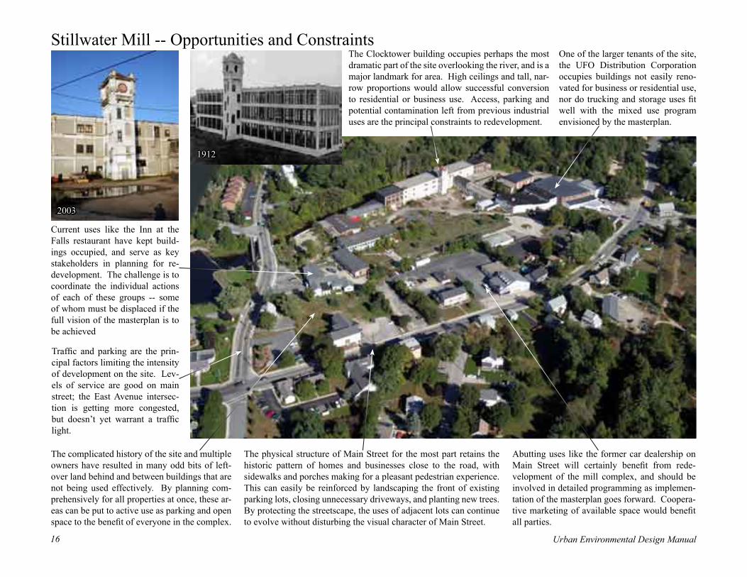
Stillwater Mill -- Opportunities and Constraints
The complicated history of the site and multiple owners have resulted in many odd bits of left-over land behind and between buildings that are not being used effectively. By planning com-prehensively for all properties at once, these ar-eas can be put to active use as parking and open space to the benefit of everyone in the complex.
Current uses like the Inn at the Falls restaurant have kept build-ings occupied, and serve as key stakeholders in planning for re-development. The challenge is to coordinate the individual actions of each of these groups -- some of whom must be displaced if the full vision of the masterplan is to be achieved
The physical structure of Main Street for the most part retains the historic pattern of homes and businesses close to the road, with sidewalks and porches making for a pleasant pedestrian experience. This can easily be reinforced by landscaping the front of existing parking lots, closing unnecessary driveways, and planting new trees. By protecting the streetscape, the uses of adjacent lots can continue to evolve without disturbing the visual character of Main Street.
One of the larger tenants of the site, the UFO Distribution Corporation occupies buildings not easily reno-vated for business or residential use, nor do trucking and storage uses fit well with the mixed use program envisioned by the masterplan.
The Clocktower building occupies perhaps the most dramatic part of the site overlooking the river, and is a major landmark for area. High ceilings and tall, nar-row proportions would allow successful conversion to residential or business use. Access, parking and potential contamination left from previous industrial uses are the principal constraints to redevelopment.
Abutting uses like the former car dealership on Main Street will certainly benefit from rede-velopment of the mill complex, and should be involved in detailed programming as implemen-tation of the masterplan goes forward. Coopera-tive marketing of available space would benefit all parties.
Traffic and parking are the prin-cipal factors limiting the intensity of development on the site. Lev-els of service are good on main street; the East Avenue intersec-tion is getting more congested, but doesn’t yet warrant a traffic light.
2003
1912

Urban Environmental Design Manual16 Urban Environmental Design Manual 17
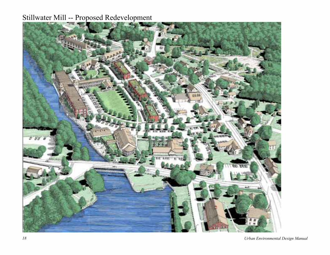
Stillwater Mill -- Proposed Redevelopment Plan
Two principal access points connect the main loop road from Main Street to Central Street, and organize interior cross streets and parking areas into a straightforward system. Parking lots interconnected with existing driveways to limit congestion at any one point.
Stillwater Heights elderly housing, including 53 apartment units, to be developed by The Community Builders, with grants from U.S. Dept.. of Housing and Urban Development.
New mixed-use buildings with ground floor retail/commercial and second floor apartments or condominiums. Parking is provided on both sides of these structures, with the street on the side of the common laid out for short-term parallel parking.
Mill #4/ Clocktower Building renovated for 50 mixed-income apartments. Both original reinforced concrete structure and later brick wings will be retained.
New “town common” will be the focal point of the project, reinforced by the surrounding buildings and the main road loop through the site.
New residential structures, con-figured as two story townhouses with formal entrances on the street side and parking lots in the rear. If possible, use of shared parking lots could allow more areas to be devoted to open space instead of parking, as shown behind the smaller of the two buildings.
This masterplan was developed by Gates, Leighton & Asso-ciates, Inc., of East Providence, RI, with New England Eco-nomic Development Services, Inc. of Lincoln, RI, on behalf of the Town of Burrillville and the Burrillville Redevelop-ment Agency. The Stillwater Heights elderly housing project was designed by Newport Collaborative Architects, Inc., on behalf of The Community Builders, Inc., who also contrib-uted to development of the overall masterplan.
New town library to be built on the site of former Mill #1, if possible incorporating portions of the former Dye house
Urban Environmental Design Manual18 Urban Environmental Design Manual 19
Stillwater Mill -- Proposed Redevelopment
Urban Environmental Design Manual18 Urban Environmental Design Manual 19
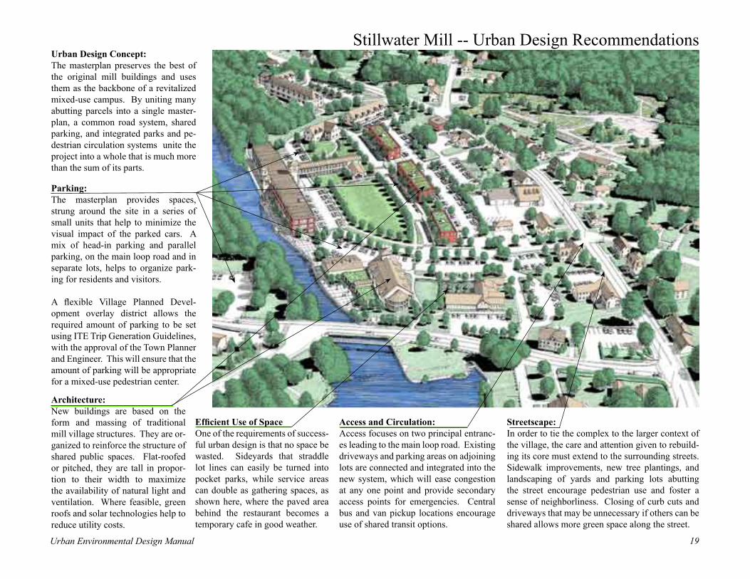
Stillwater Mill -- Urban Design Recommendations
Efficient Use of Space One of the requirements of success-ful urban design is that no space be wasted. Sideyards that straddle lot lines can easily be turned into pocket parks, while service areas can double as gathering spaces, as shown here, where the paved area behind the restaurant becomes a temporary cafe in good weather.
Architecture: New buildings are based on the form and massing of traditional mill village structures. They are or-ganized to reinforce the structure of shared public spaces. Flat-roofed or pitched, they are tall in propor-tion to their width to maximize the availability of natural light and ventilation. Where feasible, green roofs and solar technologies help to reduce utility costs.
Access and Circulation: Access focuses on two principal entranc-es leading to the main loop road. Existing driveways and parking areas on adjoining lots are connected and integrated into the new system, which will ease congestion at any one point and provide secondary access points for emergencies. Central bus and van pickup locations encourage use of shared transit options.
Streetscape: In order to tie the complex to the larger context of the village, the care and attention given to rebuild-ing its core must extend to the surrounding streets. Sidewalk improvements, new tree plantings, and landscaping of yards and parking lots abutting the street encourage pedestrian use and foster a sense of neighborliness. Closing of curb cuts and driveways that may be unnecessary if others can be shared allows more green space along the street.
Parking: The masterplan provides spaces, strung around the site in a series of small units that help to minimize the visual impact of the parked cars. A mix of head-in parking and parallel parking, on the main loop road and in separate lots, helps to organize park-ing for residents and visitors.
A flexible Village Planned Devel-opment overlay district allows the required amount of parking to be set using ITE Trip Generation Guidelines, with the approval of the Town Planner and Engineer. This will ensure that the amount of parking will be appropriate for a mixed-use pedestrian center.
Urban Design Concept: The masterplan preserves the best of the original mill buildings and uses them as the backbone of a revitalized mixed-use campus. By uniting many abutting parcels into a single master-plan, a common road system, shared parking, and integrated parks and pe-destrian circulation systems unite the project into a whole that is much more than the sum of its parts.

Urban Environmental Design Manual20 Urban Environmental Design Manual 21
Stillwater Mill -- Urban Design FocusCreating Community SpacesIn an increasingly competitive market for business, commercial and residential tenants, amenities that sup-port a high quality of life can make a big difference in sales. This has to occur both on the level of the overall masterplan, and in the details of materials and construction. One of the functions of the masterplan-ning process is to coordinate public and private invest-ments so that paths and plantings don’t end at lot lines, and materials, landscaping, lighting, etc.. are the same throughout the area. Key principles include:
Using buildings to shape space: the location and orientation of each building is designed to enclose adjoining pedestrian spaces. Major building features act as focal points that help visitors find their way and create a pleasing visual focus. The result is a series of outdoor rooms that help to organize activities and cre-ate a strong sense of place .
Integrated pedestrian system: The roads and build-ings help to reinforce a pedestrian spine that connects the Stillwater Heights project to the new library. Sec-ondary connections link each parking area and building to this system, which leads to the common and smaller gathering spaces around the complex. A continuous riverwalk runs along the edge of the Clear River and connects to a townwide trail system.
Gathering spaces form a “string of pearls:”Public spaces like the riverwalk and garden terrace out-side the library, and private gardens, outdoor cafes and sitting areas, are linked into a single system by continu-ous paths and sidewalks. At the center, the “common” is the most public space in the system, and a natural focus of activity. The surrounding smaller spaces al-low users to enjoy a range of experience from a quiet, private garden to a lively community space. The visual and social richness that results will add immeasurably to the success of the project.

Urban Environmental Design Manual20 Urban Environmental Design Manual 21
Stillwater Mill -- Recommended Stormwater Best Management Practices
Stormwater Planters:Planters around the base of the main mill building bring greenery, and a measure of privacy, close to ground-floor windows. Constructed as a continuous engineered unit, the planters absorb and filter roof runoff. Excess water not taken up by the growing plants would be collected by a perforated pipe at the bottom of the planter and carried south to the swale for eventual discharge into the river.
Grid Pavers:Runoff from many of the parking lots can be reduced with the use of pervious pavement systems. These would prob-ably not be feasible in areas with soil contamination or poor drainage, so much will depend on the more detailed surveys of site conditions that will occur as the project moves forward. Most likely, they will be most useful in higher elevations of the site where drainage is better.
Vegetated Swale:A low-tech option for areas abutting open space, a vegetated swale allows for efficient sheet drainage from the adjoining road, com-bined with continuous filtration and infiltra-tion of runoff. While the level of treatment achieved is not as high as for the more highly engineered biofiltration areas, swales provide an inexpensive way to achieve many of the same results.
Bioretention: Parking lot runoff is drained into linear filter beds and re-leased slowly back into the ground. These combine the traditional storage and me-tering function of detention basins with the advantages of filtering by plants and soil.
Green Rooftops:New construction allows for green roofs to be planned as part of the overall design of the building. While the technology is quite simple, long term success requires careful waterproofing and quality control during con-struction. Benefits include insulation from extremes of temperature, and pro-tection of roof membranes from sun damage and early failure..
Rooftop Garden: A riverfront deck built on the foundation of the dye house provides an oppor-tunity to combine a terrace gathering space with a rooftop stormwater garden. This could collect the run-off from roofs and store it for gradual use by growing plants, reducing irrigation costs.
Key to Stormwater SystemsKey to Stormwater SystemsGrid PaversGrid Pavers
Bioretention
Vegetated Swale/Stormwater Planters
Green Roof/Roof Garden

Urban Environmental Design Manual22 Urban Environmental Design Manual 23
parking spaces are used infrequently. Practices selected for the site are listed below and are designed to achieve the following objectives:
• Rooftop Garden – Reduction of runoff from rooftop impervious surfaces and overall annual pollutant load reduction;
• Green Rooftops – Reduction of runoff from rooftop impervious surfaces and overall annual pollutant load reduction;
• Bioretention – Treatment of first inch of runoff from upland impervious surfaces;
• Stormwater Planters – Treatment of first inch of runoff from rooftop impervious surfaces;
• Vegetated Swale – Treatment of first inch of runoff from upland impervious surfaces; and
• Grid Pavers – Reduction of runoff for area constructed as grid pavers and overall annual pollutant load reduction.
Stillwater Mill -- Selection and Design of Stormwater BMPsThe Stillwater Mill site is a former industrial complex located immediately adjacent to the Clear River. The site was most certainly filled above the natural floodplain, which creates a number of constraints and opportunities for stormwater management. A riverine floodplain overlaid by fill, coupled with historic industrial uses, suggests severe limitations for infiltration of stormwater runoff. Subsurface soils will likely be ill suited for infiltration of significant amount of runoff and will likely hold contaminants that are better left undisturbed.
Furthermore, because the site is a redevelopment project with little or no increase in impervious cover, and is located immediately adjacent to a major river system, attenuation of peak flows from larger storms may cause more harm than good. In the absence of a watershed hydrologic flooding assessment that designates specific locations and attenuation goals for stormwater flood control, it can be safely assumed that the implementation of quantity controls for this site may actually increase peak flow rates downstream due to the phenomenon of coincident peaks (i.e., runoff from this site is retained until upstream peak flows arrive at the site, thereby resulting in a net increase in peak flow rate in the river).
As a result, the recommended stormwater measures for the Stillwater Mill site are all prescribed to meet water quality control objectives. In general, infiltration practices are not considered for water quality control due to soil/high groundwater limitations and the potential for subsurface contamination. The only exception is the use of grid pavers at a few overflow-parking locations. These would be applied only after a detailed subsurface investigation confirms suitable soils that are contaminant free and only in on-site locations where
The bioretention systems, stormwater planters and the vegetative swales will provide water quality treatment for precipitation up to the 1-inch storm. The rooftop garden, green rooftops and grid pavers all reduce runoff volume when evaluated on an annual basis. The degree of runoff reduction can vary widely (from 20 to 80%) depending on time of year, rainfall intensity, compaction of the underlying soils, type of grid pavers applied, and whether an “intensive” or “extensive” green roof is employed.
The stormwater management practices applied at the site are designed to be consistent with Rhode Island’s stormwater management manual, given the following assumptions:
• The redevelopment site will have a net reduction in effective impervious cover, through a combination of green roofs, rooftop gardens, grid pavers, and removal and/or repaving of existing impervious cover;
• Runoff from new roads, parking areas and new buildings will be conveyed to either bioretention facilities, or vegetative swales for water quality treatment;
• Stormwater planters will effectively treat rooftop runoff from the Clocktower Building; and
• Stormwater quantity controls are not necessary unless a regional flood control study has identified the site location as
necessary for stormwater detention. If the project were located further away from the Clear River and drained to a smaller stream or conveyance channel, additional stormwater quantity controls would likely be required for any increased impervious cover from new parking, roads and buildings.
Green rooftops can play a valuable aesthetic role in redevelopment, extending landscaping across areas that would otherwise be barren eyesores. Photo courtesy of City of Portland, Stormwater Management Manual, 2002

Urban Environmental Design Manual22 Urban Environmental Design Manual 23
Rau Fastener -- Existing Conditions Before Redevelopment

Urban Environmental Design Manual24 Urban Environmental Design Manual 25
Rau Fastener -- Introduction to the SiteThe Rau Fastener Complex is embedded in the rich fabric of the West End neighborhood of Providence. In operation from the late 19th century until the 1990’s, the complex includes three and four story brick mill buildings, a two story wood mill structure, and a 1950’s era two-story addition. Surrounded by a mixture of residential, commercial and industrial uses in a remarkable variety of shapes and sizes, the complex reflects the complicated his-tory of landuse in the neighborhood. While abandonment, decay and disinvestment have troubled the area, the rich historic structure of the neighborhood remains. Renovation and adaptive reuse of the old mill buildings and surrounding residential structures can take advantage of the human scale and strong sense of place left behind by generations of use. Nearby parks, schools, churches and city services create an opportunity for a truly mixed-use, walkable neighborhood.
Rau Fastener Complex Dexter Street
Boarded-up windows and a 1950’s addition obscure the historic architectural character of the original brick mill buildings.
The courtyard passage between the two original mill structures offers possibilities for a dramatic entrance to the complex.
A view looking East from the project site down West-field St. A strong grid of streets ties the complex to the surrounding neighborhood.
Photo #1
Photo #2 Photo #3

Urban Environmental Design Manual24 Urban Environmental Design Manual 25
Rau Fastener -- Neighborhood Context
The West End neighborhood is Providence’s largest, with almost 16,500 residents in 2000. It is also one of the most diverse, with 30% Hispanic, 18.7% African-American, and 13.1% Asian residents. More than one in three is foreign-born, illustrating the role of the area as a first home for new immigrants. The rich history of the area mirrors economic and social changes in the city since the 17th century, with most structures dating from the boom times that followed the civil war. Like Rau Fastener, many of the industries that pow-ered the neighborhood’s growth have moved on, leaving behind a legacy of sturdy brick mill buildings and dense residential streets. (source: Providence Plan).
The Cranston Street Armory, home of the RI National Guard from 1907-1996, is currently vacant. Together with the adjacent Dexter Parade Ground, it is a major focal point of the neighborhood.
Nearby residential streets illustrate the rich sense of place created by an earlier society where most people lived and worked in the same neighborhood and walked everywhere they needed to go.
Cranston Street Armory
Rau Fastener Complex
Bucklin ParkStuart Elementary School
Buck
lin A
ve.
Dexter Street
Elmwoo
d Ave
.
Westminster Street
Urban Environmental Design Manual26 Urban Environmental Design Manual 27
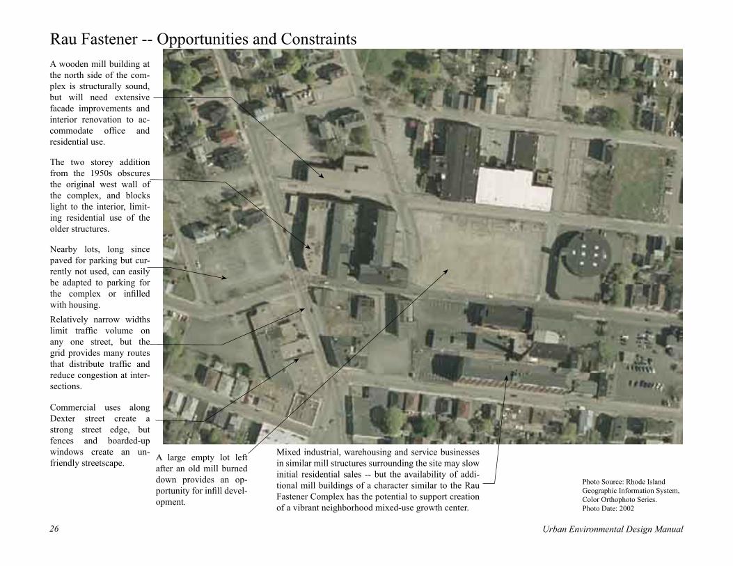
Rau Fastener -- Opportunities and Constraints
Commercial uses along Dexter street create a strong street edge, but fences and boarded-up windows create an un-friendly streetscape.
Relatively narrow widths limit traffic volume on any one street, but the grid provides many routes that distribute traffic and reduce congestion at inter-sections.
A large empty lot left after an old mill burned down provides an op-portunity for infill devel-opment.
Nearby lots, long since paved for parking but cur-rently not used, can easily be adapted to parking for the complex or infilled with housing.
The two storey addition from the 1950s obscures the original west wall of the complex, and blocks light to the interior, limit-ing residential use of the older structures.
Mixed industrial, warehousing and service businesses in similar mill structures surrounding the site may slow initial residential sales -- but the availability of addi-tional mill buildings of a character similar to the Rau Fastener Complex has the potential to support creation of a vibrant neighborhood mixed-use growth center.
A wooden mill building at the north side of the com-plex is structurally sound, but will need extensive facade improvements and interior renovation to ac-commodate office and residential use.
Photo Source: Rhode Island Geographic Information System, Color Orthophoto Series.Photo Date: 2002

Urban Environmental Design Manual26 Urban Environmental Design Manual 27
Rau Fastener -- Proposed Redevelopment Plan
Vacant lots to be paved and landscaped to accommo-date the necessary parking for the complex.
1950’s addition to the original Rau Fastener buildings to be razed and replaced with parking and landscaping. Plans coordi-nated with construction of new bus stop to encourage use of public transporta-tion.
A portion of the existing empty lot will be reserved for a new public park with pedestrian paths and plantings.
Existing residential, com-mercial and industrial structures are shown in grey. Structures shown in tan include new single family structures as infill on currently vacant lots.
Historic brick mill build-ings will be renovated into sixty-nine affordable and market rate artist studio loft apartments.
Twenty-two new three-story attached residential townhouses will be built on vacant lot. Interior alley provides access to rear gardens and garage parking under each unit.
This site redevelopment masterplan and architec-tural concepts were created for the West Elmwood Housing Development Corporation by Durkee, Brown, Viveiros & Werenfels Architects, Inc. 300 West Exchange Street, Providence, RI 02903.
Wooden mill building will be adapted for mixed-use business occupancy, including community based day care center and technology based business offices.

Urban Environmental Design Manual28 Urban Environmental Design Manual 29
Rau Fastener -- Proposed Redevelopment

Urban Environmental Design Manual28 Urban Environmental Design Manual 29
Rau Fastener -- Urban Design Recommendations
Residential Infill: New single family homes reinforce the neighborhood character of streets surrounding the complex. Site layout and architectural design can be based on the many historic structures nearby. Parking in side and rear of units allows for an at-tractive dooryard and streetscape.
Landscape: With a relatively small proportion of the site not used for buildings or parking, landscap-ing focuses on pedestrian courtyards and pocket parks integrated into a continuous system of sidewalks and paths. Careful preparation of subdrainage and soils, and planning for irrigation and maintenance al-lows for heavy use throughout the year.
Access: By maintaining the existing grid of streets, there is ample vehicular access for each building in the complex. Continuous sidewalks and paved gathering spaces mini-mize conflicts between cars and pedestrians, and encourage use of public transportation. Service and deliveries can be accommodated in marked spaces and off-hour use of street loading zones.
Streetscape: The design of sidewalks, dooryards and building facades creates a welcoming public face for the development. Continuous plant-ings of shade trees shelter the sidewalks, cool parking areas, and filter street noise and dust. Building entrances, porches and stoops are carefully designed to enhance social activi-ties and add to visual interest of the street.
Parking: The practical requirements of at least one parking space per dwell-ing unit force large areas to be turned over to parking lots. While in some urban neighborhoods this can force developers to tear down historic structures for park-ing, here there are enough empty lots to fit what is needed. As the neighborhood evolves, these can be replaced with garages to accommodate more cars. Mean-while, on-street parking allows for special events and visitors.
Urban Design Concept: Redevelopment of the old mills and infill of empty lots with town-houses and single family homes is designed to reinforce the historic pattern of streets and blocks in the neighborhood. While the plan ac-commodates the modern need for automobiles, it is driven by a more traditional pedestrian lifestyle, where broad shaded sidewalks, courtyards and small parks form a continuous system connecting home, workplace, commercial and civic uses.

Urban Environmental Design Manual30 Urban Environmental Design Manual 31
Rau Fastener -- Urban Design FocusTownhouse Infill for a Vacant City LotRather than trying to turn urban neighbor-hoods into suburban style subdivisions, use of the traditional city townhouse block, as illus-trated here, can reclaim empty lots with a form that uses land and building materials much more efficiently. As a result, the cost of land per unit is more reasonable. Careful attention to the design of the streetscape, and provision of private parking and garden spaces for each unit provide the amenities that residents are looking for in a single family home.
Proposed architectural elevation as developed by Durkee, Brown, Viveiros & Werenfels Architects
Elements of the Townhouse ApproachEfficient building form: the simple continuous build-ing block is inexpensive to build and maintain, while a full three storeys provide large floor area for each unit.
Automobile access: an alley provides vehicular access to the rear of each unit, each of which has a private drive and ground-floor garage.
Private open space: small garden spaces and indi-vidual porches provide a private yard in the rear of each home.
Public open space: sidewalks connect each unit to larger park space at the end of the block. Urban liv-ing can provide a high quality of life by allowing easy pedestrian access directly from the home to city parks and playgrounds.
Architectural character: simple bay windows and decorative entrances provide visual interest and func-tionality for each unit.
Classic city living: the combination of broad side-walks, trees, attractive front facades and stoops is a classic formula for comfortable in-town living.

Urban Environmental Design Manual30 Urban Environmental Design Manual 31
Rau Fastener -- Recommended Stormwater Best Management Practices
Stormwater Planters:Planters around the base of the mill struc-tures establish a privacy setback from ground floor windows, while providing for permanent and seasonal plantings that soften the hard edges of the buildings.
Roof Gardens:The roof areas of the one story wings surrounding the interior courtyard are sheltered and visible sur-rounding upper-story win-dows. Roof gardens here will extend usable outdoor space while providing insulation and summer cooling. Grid Pavers:
Grid pavers help to demarcate pedes-trian paths through the park space, while allowing for stormwater to soak back into the ground.
Bioretention: Parking lot runoff is directed to central locations for filtering and recharge to groundwater.in subsurface drainage beds or chambers..
Lined Bioretention:Where soil conditions or potential contamination limit potential for infiltra-tion of stormwater, bio-retention is used to slow and filter runoff, which is collected by an impervi-ous liner and piped to other areas.
Bioretention/Rain Gardens:Rain gardens combine the practical function of bioretention and groundwater recharge while pro-viding lush green space outside each home. Care-ful selection of plant materials ensures year-round visual interest.
Porous Pavement: Porous paving blocks help to infiltrate rainwater back into the ground, while cre-ating an attractive surface for pedestrian areas around a building entrance.
Key to Stormwater SystemsKey to Stormwater SystemsPorous Pavement/Grid PaversPorous Pavement/Grid Pavers
Rain Garden/Bioretention
Stormwater Planters
Green Roof/Roof Garden

Urban Environmental Design Manual32 Urban Environmental Design Manual 33
Rau Fastener -- Selection and Design of Stormwater BMPs The Rau Fastener site is completely surrounded by existing development and served by network of subsurface drainage pipes with adequate capacity to carry stormwater runoff away from the project site. The Rau Fastener building itself is viewed as a historic resource and the roof material would need to be compatible with historic preservation objectives. The Rau Fastener site was a former industrial manufacturing operation with documented subsurface contamination in soils immediately below and adjacent to the existing mill buildings. Soils below the proposed parking lots (away from the existing mill buildings) may offer opportunities for the application of infiltration practices. Because the site drains via pipes with adequate capacity to carry the 10-year storm from the project and because there is a net reduction in total impervious cover, stormwater quantity controls are not necessary.
Based on the initial site assessment, the recommended stormwater measures for the Rau Fastener site are all designed to meet water quality control objectives. In general, infiltration practices are not considered for water quality treatment due to the potential for subsurface contamination. The only exception is the use of porous pavement blocks for pedestrian courtyards and grid pavers for sidewalks. Both of these areas are located a significant distance from known areas of subsurface contamination. Application of porous pavers would be implemented only after a detailed subsurface investigation confirms suitable soils that are contaminant free and only for pedestrian surfaces.
Practices selected for site are listed below and are designed to achieve the following objectives:
• Rooftop Garden – Reduction of runoff from rooftop impervious surfaces and overall annual pollutant load reduction;
• Bioretention – Treatment of first inch of runoff from upland impervious surfaces;
• Stormwater Planters – Treatment of first inch of runoff from rooftop impervious surfaces;
• Vegetated Swale – Treatment of first inch of runoff from upland impervious surfaces; and
• Porous Pavement Blocks/Grid Pavers – Reduction of runoff for area constructed as grid pavers and overall annual pollutant load reduction.
The bioretention systems, stormwater planters and the vegetative swales will provide water quality treatment for precipitation up to the 1-inch storm. The rooftop garden, porous pavement blocks, and grid pavers all reduce runoff volume when evaluated on an annual basis. The degree of runoff reduction can vary widely (from 20 to 80%) depending on time of year, rainfall intensity, compaction of the underlying soils, type of
grid pavers applied, and whether an “intensive” or “extensive” green roof is employed.
The stormwater management practices applied at the site are designed to be consistent with the goals of Rhode Island’s stormwater management manual, given the following assumptions:
• The redevelopment site will have a net reduction in effective impervious cover, through a combination of rooftop gardens, porous pavement blocks, grid pavers, and removal and/or repaving of existing impervious cover;
• Runoff from new roads, parking areas and new buildings will be conveyed to either bioretention facilities, or vegetative swales for water quality treatment;
• Stormwater planters will effectively treat rooftop runoff from the existing mill building; and
• Because the site directly discharges to an existing drainage network with adequate capacity to convey the 10-year frequency storm and because there is no increase in impervious cover, stormwater quantity controls are not necessary.
Stormwater planters work well in urban neighborhoods where careful design detailing, durability and maintenance requirements are important factors in the success of the project. Photo courtesy City of Portland Stormwater Management Manual, 2002,

Urban Environmental Design Manual32 Urban Environmental Design Manual 33
Tidewater -- Existing Conditions Before Redevelopment

Urban Environmental Design Manual34 Urban Environmental Design Manual 35
Tidewater -- Introduction to the SiteThe Tidewater site has been an important part of the City of Pawtucket’s vision for the future since completion of a Riverfront Development Plan in 1976. The core of the area is a 28 acre industrial property that includes a former coal gas-ification plant that operated from 1881 to 1954. Just to the South, Narragansett Electric operates a substation that must remain in place as other areas are redeveloped. To the north, the City’s Paw-tucket Landing park provides a boat launch and fishing pier, and from there it is less than a mile up river to City Hall.
Potential contamination of the site with by-products of the coal gas plant have long been of concern to residents and city officials, and have delayed redevelopment. Site investigations and feasibility studies completed over the last 20 years have concluded that while contamination is present, it does not preclude reuse of the site. As a practical matter, however, the level of mitiga-tion required for residential use will likely not be economically feasible. As a result the most likely scenario sees the site redeveloped for industrial or commercial use, with a riverfront park connecting the Town Landing with ball fields to the south of the property.
At a workshop in the summer of 2003, city of-ficials and residents helped to develop a series of plan concepts for the site, one of which is il-lustrated on the following pages. The preferred plans for the study area see a mix of open space and mixed commercial/office development, which would bring economic growth to the city and help to fund reclamation of the area.
Downtown Pawtucket
Boat Launch and Fishing Pier
Charter School
Electrical Substation
Electric Company Facilities
Public Landing
Interstate 95
Electrical Transmission Tower
Gas Tanks
Gas Company Property
Gas Pumping Station
The electric company’s transmission towers and substation will remain in operation, but the existing brick buildings are no longer needed.
The site commands a dramatic sweep of the river, which will be its principal asset once fences are re-moved and the site cleaned up.

Urban Environmental Design Manual34 Urban Environmental Design Manual 35
Tidewater -- Neighborhood ContextThe Tidewater site, once merely the anony-mous South end of Pawtucket’s industrial waterfront, now promises to benefit from a unique location where the Blackstone River meets the tidal waters of Narragansett Bay. Only a few minutes from downtown Paw-tucket and I-95, it is the gateway to the South side of the city, which blends nearly seam-lessly into Providence’s East Side. For the immediate neighborhood, reclamation of the site represents a chance for more open space. Recent masterplans for the river corridor propose a continuous park along the water’s edge, balanced by economic development on the interior of the site. Regardless of where and how this balance is finally reached, plan-ning for the site itself holds the promise of creating a wonderful focus for the surround-ing neighborhood, and reconnecting its resi-dents to the river.
Tidewater Site
Interstate 95
Providence
Slater MillBlackstone River
Hidden from ground level by fences and vegetation, from the air the site is tied closely to the neighborhood.
Quiet residential streets, two schools and recreation fields abut the site.
Blackstone Boulevard
PawtucketProposed Hotel Site
A city fishing pier at the north end of the site is just a short way from downtown Pawtucket.
State Pier
Taft Street
Town Landing
Seekonk River

Urban Environmental Design Manual36 Urban Environmental Design Manual 37
Tidewater -- Opportunities and Constraints
Narragansett Electric, now part of National Grid, will continue to operate a substation on the site. In line with safety policies that prefer that transformers and other equipment be kept outdoors, the large brick building will no longer be needed. New substation equipment can be built further south, making some of the electric company property available for redevelopment.
The Francis J. Varieur Elementary School was built on land bought from the Blackstone Valley Electric Com-pany in the 1960’s. Classes study the river adjacent to the ballfields just south of the site, and would benefit from paved paths to the waters edge.
Quiet since operations ceased in the 1950s, land owned by the gas company includes landfill containing ferric ferrocyanide, a byproduct of the coal gasification process. Studies have shown that these contaminants are stable, and cannot be released by con-tact with groundwater or leached out into the river. The recom-mended approach is clean up of the surface layers and capping of landfilled material, allowing reuse for non-residential purposes.
The city recently completed a boat launch and fishing pier known as the Town Landing, and has concepts showing additional parking and a structure to accommodate water-based transportation. Actively use by fishermen, the site includes several acres of woods and a turnout and parking area off Taft Street. A steep bank separates the river’s edge from most of the Taft Street frontage, limiting pedestrian access for all but the most adventurous.
The site of a new hotel, now under plan development, looks directly out on the Tidewater site. Redevelopment of similar sites will become more common as public improvements to river front parks, clean up of former industrial land, and improvements in water quality in the river are completed.
Neighborhood Streets run at right angles to the wa-terfront, with sidewalks that would allow residents easy access to the site once fences are removed. The streets also create view corridors from which glimpses of the water can already be seen. En-hancing this visual and physical connection could reconnect the neighborhood to the waterfront.
Taft Street
Narragansett Electric Company
City of Pawtucket
Blackstone Valley Gas Company
VarieurElementary School
Charter School
Fuel Storage Tanks
Gas Pumping Station
NorthPhoto Source: Massachusetts Geographic Information System
Color Orthophoto Series; photo date, April, 2001.

Urban Environmental Design Manual36 Urban Environmental Design Manual 37
Tidewater -- Proposed Redevelopment Plan
National Grid will continue to operate a substation on the site, but new facilities will be constructed further to the south as existing ones are upgraded. New fences and plant-ing will provide screening. Unneeded areas along the river will become part of the riverfront park, connecting the Town Landing with the ballfields and accommodating the eventual extension of the Blackstone Bikeway to Providence.
The proposed development provides a flex-ible range of footprint sizes, allowing for a mix of commercial and office uses. While they may be developed as individual lots, the structures fit within an overall master-plan where access and parking is shared, allowing for the most efficient layout.
A new boathouse will provide a center for rowing and sailing on the river. Located at the most visible point at the bend in the river, the facility would act as a focal point and landmark both from the land and water sides. Towers, viewing platforms and signal flags used for crew events add visual interest and ex-citement. During the week, facilities to accommodate school children turn the boathouse into a river education center.
A new frontage road creates a main entrance to the site adjacent to Pawtucket Landing, limiting the impact of increased traffic on the quiet residential streets of the existing neighborhood. Lined by buildings carefully placed to form a nearly continuous wall, the road incorporates broad sidewalks shaded by trees to encourage walking. Parallel on-street spaces provides for short-term parking.
A large informal play field is the focus of activity, framed by trees at either end. Po-tential extension of the Blackstone Bikepath could be accommodated along the water’s edge. Plantings of native trees, shrubs and grasses create a riparian buffer along the edge of the river.
Neighborhood streets are extended into the site, inviting residents to walk down to the new park and maintaining view corridors to the river. The design of streets, sidewalks and plantings within the site can be coordinated with streetscape im-provements on existing streets to further tie the neighborhood to the Tidewater development..
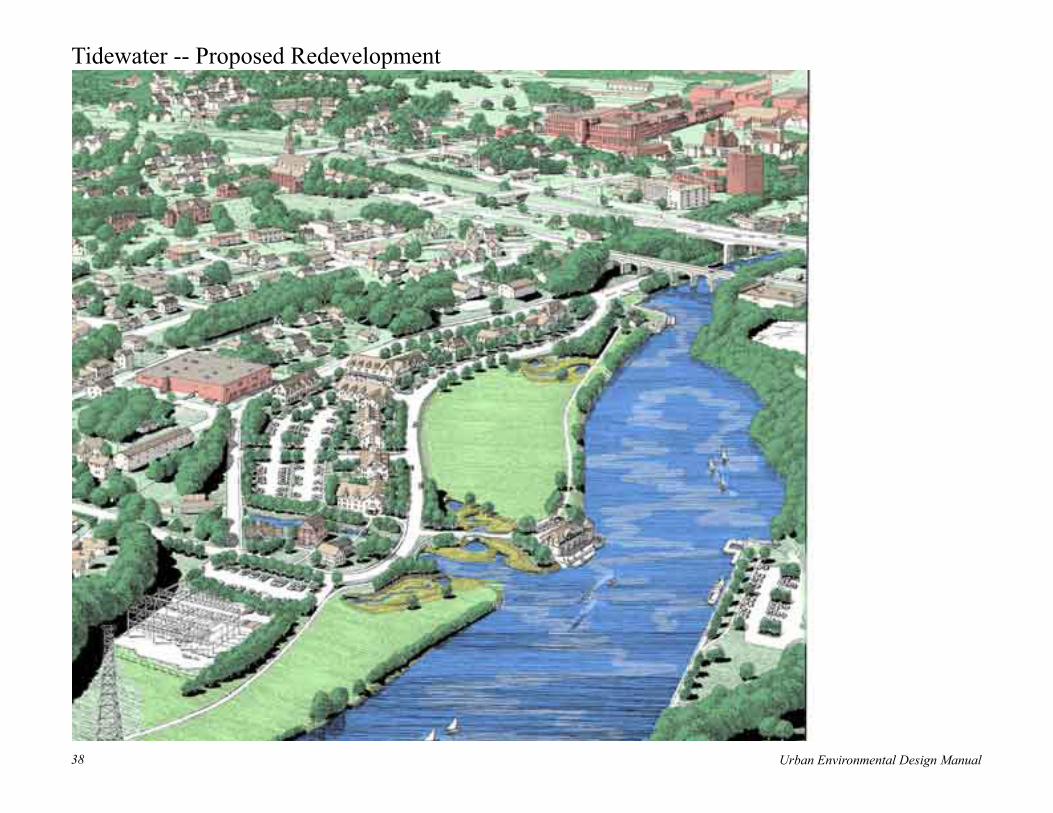
Urban Environmental Design Manual38 Urban Environmental Design Manual 39
Tidewater -- Proposed Redevelopment
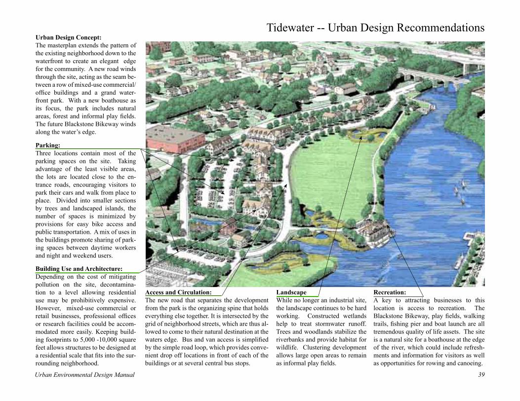
Urban Environmental Design Manual38 Urban Environmental Design Manual 39
Tidewater -- Urban Design Recommendations
Landscape While no longer an industrial site, the landscape continues to be hard working. Constructed wetlands help to treat stormwater runoff. Trees and woodlands stabilize the riverbanks and provide habitat for wildlife. Clustering development allows large open areas to remain as informal play fields.
Building Use and Architecture: Depending on the cost of mitigating pollution on the site, decontamina-tion to a level allowing residential use may be prohibitively expensive. However, mixed-use commercial or retail businesses, professional offices or research facilities could be accom-modated more easily. Keeping build-ing footprints to 5,000 -10,000 square feet allows structures to be designed at a residential scale that fits into the sur-rounding neighborhood.
Access and Circulation: The new road that separates the development from the park is the organizing spine that holds everything else together. It is intersected by the grid of neighborhood streets, which are thus al-lowed to come to their natural destination at the waters edge. Bus and van access is simplified by the simple road loop, which provides conve-nient drop off locations in front of each of the buildings or at several central bus stops.
Recreation: A key to attracting businesses to this location is access to recreation. The Blackstone Bikeway, play fields, walking trails, fishing pier and boat launch are all tremendous quality of life assets. The site is a natural site for a boathouse at the edge of the river, which could include refresh-ments and information for visitors as well as opportunities for rowing and canoeing.
Parking: Three locations contain most of the parking spaces on the site. Taking advantage of the least visible areas, the lots are located close to the en-trance roads, encouraging visitors to park their cars and walk from place to place. Divided into smaller sections by trees and landscaped islands, the number of spaces is minimized by provisions for easy bike access and public transportation. A mix of uses in the buildings promote sharing of park-ing spaces between daytime workers and night and weekend users.
Urban Design Concept: The masterplan extends the pattern of the existing neighborhood down to the waterfront to create an elegant edge for the community. A new road winds through the site, acting as the seam be-tween a row of mixed-use commercial/office buildings and a grand water-front park. With a new boathouse as its focus, the park includes natural areas, forest and informal play fields. The future Blackstone Bikeway winds along the water’s edge.

Urban Environmental Design Manual40 Urban Environmental Design Manual 41
Tidewater -- Urban Design FocusIntegrating Development and Open SpaceThe most memorable urban places often combine dense clusters of buildings and lively streets with magnificent open spaces. Riverfronts naturally lend themselves to this combination of elements, and have the further advantage of forming a linear connection between key gathering places, each of which can be a focal point for a town or city neighborhood. With this in mind, the de-sign of the Tidewater site should blend open space with developed areas in many different ways, each of which adds to the interest and visual character of the whole:
Structures and StreetscapeThe siting of each building is carefully thought out in relation to the street and to other buildings. A common setback line creates a continuous wall, turning the side-walk into a long outdoor room, sheltered by trees on the street side, and punctuated by gardens and sitting areas. Parallel on-street parking allows visitors to stop outside each building, and views of the park and river will encourage gathering at sidewalk cafes.
Private, Public and Transitional SpacesOne of the keys to successful urban design is to cre-ate a system of outdoor spaces with varied degrees of privacy. Directly outside shops or offices there might be private terraces used only by customers or employ-ees; along the street a transitional zone invites window shopping and would be used most by those going to and from buildings; the great open space along the river is the most public part of this system. Visitors from other parts of the city or region would feel comfortable here, as in any public park.
Varied Pedestrian Experience An environment like this one is best experienced on foot. With care, sidewalks along the street can be linked with paths through the open space to create a continuous network connecting the most important buildings and gathering spaces.. This in turn would be lined to destinations up and down the river by the bike path, and by sidewalks to rest of the neighborhood.

Urban Environmental Design Manual40 Urban Environmental Design Manual 41
Tidewater -- Recommended Stormwater Best Management Practices
Constructed Wetlands:Land dedicated as park space along the riverfront can be made to serve double duty: helping to deal with stormwater runoff from the site and parts of the adjoining neighborhood. Designed as a series of alternating pools and meandering marshes, constructed wetlands clean the stormwater while adding visual interest and wildlife view-ing opportunities for park visitors. In addition to their biological and aesthetic functions, these new wetlands also replace those that historically would have lined the riverbank, once again providing shelter and habitat to wildlife. And like natural wetlands, they are largely self-maintaining, growing and shrinking in response to the available moisture.
Stormwater Planters and Cistern:Runoff from roof areas and decks is directed to planters that soften the lines of the boat-house. Filtered by its passage through the plants and soil of the planters, any excess water can be stored in cisterns for later use irrigating plantings or washing boats and equipment.
Riparian Buffer Plantings:Large open turf areas can shed water during heavy rains. In this case, low areas adjacent to the river are planted with taller species of native grasses and wildflowers, which slow down the runoff and take up excess nu-trients before they reach the river. Seasonal displays of flowers and foliage make a nice counterpoint to mowed turf areas.
Vegetated Swale: The length of roadway ad-jacent to the riverfront park is ideal for a swale, which can be graded to blend in gradually with the open meadow. Longer grasses in the swale slow water flow and filter the larger particles out before discharging the overflow to the wetlands.Daylighted Stream and Vegetated Buffers:As with many riverfront industrial sites, old streams were culverted and filled over to make room for in-dustry. By giving up a little space for nature, the stream can easily be uncovered and rebuilt. Plantings of native species help to stabilize its banks and filter runoff from adjoining areas, and weirs and other devices can be used to further settle and aerate stream water before it enters the river.
Lined Bioretention: Potential for subsurface contamination on the site limits the ability to recharge stormwater directly to the ground. Lined bioretention allows water to be filtered slowly through beds at the center and edges of each parking lot. Water drains from the bottom of the filter beds into a perforated pipe for transport to nearby con-structed wetlands.
Key to Stormwater SystemsKey to Stormwater SystemsRain Garden/BioretentionRain Garden/Bioretention
Vegetated Swale
Constructed Wetland
Cistern
Vegetated Buffer

Urban Environmental Design Manual42 Urban Environmental Design Manual 43
• Native Plantings – Reduction of runoff and habitat enhancement along the waterfront; and
• Daylighted Streams and Vegetative Buffers – Re-establishment of stream habitat and creation of vegetative buffer zones for reducing runoff and stormwater treatment of immediately adjacent areas.
The constructed wetlands, bioretention systems, stormwater planters and the vegetative swales will provide water quality treatment for precipitation up to the 1-inch storm. The native plantings, daylighted stream and vegetative buffers are designed to provide multiple benefits including establishment of aquatic and terrestrial habitats for a variety of flora and fauna, reduction of runoff, protection of stream and river banks from erosion, increased pollutant removal, stream temperature abatement, and providing a corridor for conservation and species migration.
Tidewater -- Selection and Design of Stormwater BMPsThe tidewater site is located immediately adjacent to the Seekonk River and much of the site is within the 100-year floodplain. Upland offsite runoff is conveyed through the project location within existing storm drainage pipes, which include streamflow that was at one time above-ground. The Tidewater site was a former electrical generation and fuel processing operation with documented subsurface contamination in soils. Because the site discharges directly to tidal waters of the Seekonk River, stormwater quantity controls are not necessary, provided the discharge is non-erosive.
Based on the initial site profile, the recommended stormwater measures for the Tidewater site are all designed to meet water quality control objectives. Infiltration practices are not considered for water quality control due to the potential for subsurface contamination. Because the site discharges directly to tidal waters, and a nearby boat ramp that is a favored fishing location, preference is given to stormwater practices that have higher nitrogen and bacteria removal capabilities.
Practices selected for the site are listed below and are designed to achieve the following objectives:
• Bioretention – Treatment of first inch of runoff from upland impervious surfaces and lined to prohibit leaching into subsurface areas;
• Stormwater Planters – Treatment of first inch of runoff from rooftop impervious surfaces;
• Vegetated Swales – Treatment of first inch of runoff from upland impervious surfaces;
• Constructed Wetlands – Treatment of first inch of runoff from upland impervious surfaces;
• Cistern – Reduction of annual runoff volume and reduced demand for potable water for irrigation;
The stormwater management practices applied at the site are designed to be consistent with the goals of Rhode Island’s stormwater management manual, given the following assumptions:
• The redevelopment site will discharge directly to tidal waters in a non-erosive manner;
• Runoff from new roads, parking areas and new buildings will be conveyed to constructed wetlands, bioretention facilities, or vegetative swales for water quality treatment;
• Stormwater planters will effectively treat rooftop runoff from the proposed boathouse building;
• The stormwater collection cistern is provided to reduce irrigation needs and reduce net annual runoff volume; and
• Because the site discharges directly to tidal waters in a non-erosive manner, stormwater quantity controls are not necessary.
The typical constructed pond/wetland system duplicates the functions of a natural system by recreating elements that allow for aeration and settling of runoff, filtration of contaminants, and absorption of nutrients by living plants. (Source: Schueler, 1992.)

Urban Environmental Design Manual42 Urban Environmental Design Manual 43
Central Falls -- Existing Conditions Before Redevelopment
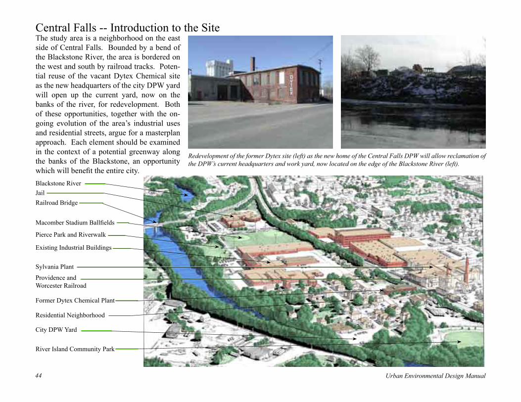
Urban Environmental Design Manual44 Urban Environmental Design Manual 45
Central Falls -- Introduction to the SiteThe study area is a neighborhood on the east side of Central Falls. Bounded by a bend of the Blackstone River, the area is bordered on the west and south by railroad tracks. Poten-tial reuse of the vacant Dytex Chemical site as the new headquarters of the city DPW yard will open up the current yard, now on the banks of the river, for redevelopment. Both of these opportunities, together with the on-going evolution of the area’s industrial uses and residential streets, argue for a masterplan approach. Each element should be examined in the context of a potential greenway along the banks of the Blackstone, an opportunity which will benefit the entire city.
Jail
Existing Industrial Buildings
Blackstone River
Residential Neighborhood
Former Dytex Chemical Plant
Railroad Bridge
River Island Community Park
Sylvania Plant
City DPW Yard
Providence and Worcester Railroad
Pierce Park and Riverwalk
Redevelopment of the former Dytex site (left) as the new home of the Central Falls DPW will allow reclamation of the DPW’s current headquarters and work yard, now located on the edge of the Blackstone River (left).
Macomber Stadium Ballfields

Urban Environmental Design Manual44 Urban Environmental Design Manual 45
Central Falls -- Neighborhood ContextLike many old mill towns, Central Falls is moving from an industrial economy of smokestacks and three deckers to an uncertain future. Contrasting land uses and devel-opment proposals in the neigh-borhood illustrate the transitions that the city is going through. Re-gional attention to the Blackstone River (right) is bringing activity to the waterfront, with a new boat landing and proposed development just North of the study area. The old brick Blackstone Falls Mill was renovated for senior housing. At the opposite end of the study area, a detention center and adjacent junkyard illustrate an earlier view of the river’s value. Whatever the future holds, the quality of life created by the continued clean-up of the river, completion of the Black-stone Bikeway and other programs will make Central Falls an even better place to live and work. The city can capitalize on this by plan-ning proactively for the study area.
Blackstone River
River Island Park
Valley Falls Landing
Dytex Site
Providence & Worcester
Railroad
Sylvania Plant
The proposed Valley Falls Landing capitalizes on pub-lic investments in improving the river and river access.
Broad Street is lined with shops and businesses that cater to residents working in local industries .
Broad Street
Quiet residential streets are lined with one, two and three-family homes. Most are neat and well cared-for.
Pawtucket
Blackstone Falls Mill

Urban Environmental Design Manual46 Urban Environmental Design Manual 47
Central Falls -- Opportunities and Constraints
The potential Central Falls Landing project with its new boat docks, along with the completed Black-stone Falls senior housing in a renovated mill across the road, bring a concentration of activity to the north end of the study area. Just across the Broad Street Bridge, the Valley Falls Heritage Park awaits a level of use that will drive away undesirable activities.
Recent completion of River Island Community Park forges a major link in a potential river greenway connecting Valley Falls Heritage Park with Pierce Park. Wooded banks across the river in Cumberland help to create a natural feeling at the edge of the city.
The Dytex Chemical Company produced chemicals for swim-ming pools, but by the 1990s was bankrupt and abandoned. The U.S. EPA was called in under the Superfund program to assess the threat posed by 1,100 drums of flammables, poisons, corro-sives and cyanide. EPA worked with RIDEM to safely remove all of these materials, and the site appears to be largely free of contamination. (Source: U.S. EPA New England Web Site.)
Like other junkyards along the Blackstone, this one was probably started when the river was too pol-luted to appeal to other uses. Now that the river is getting cleaner, it makes little sense to continue using its banks to park cars.
A variety of light industrial and service busi-nesses occupy a complex of buildings in the center of the site. While there is no reason these should not stay in place, as the river continues to improve as a regional resource opportunities will increase for converting these to uses that take advantage of the river.
Abutting uses, including the Sylvania Plant and mixed commercial, industrial and residential uses along Broad Street, are unlikely to change in the near future. This will likely maintain the population density on and near the study area, a population that will benefit greatly from addi-tional housing and recreational opportunities.
The city’s DPW yard occupies a site at the edge of the river in an otherwise residential neighborhood. The riverbank here is one of the few places that you can get close to the river and enjoy an uninterrupted view of the water.
Broad Street
High Street
Blackstone River

Urban Environmental Design Manual46 Urban Environmental Design Manual 47
Central Falls -- Proposed Redevelopment Plan
A new residential street is built from the former Dytex building to River Island Park. Replacing what is now trucking company trailer storage, the new homes reinforce the edge of the existing neigh-borhood and bring new life and activity to the area around the park.
As the value of riverfront locations increases, new office buildings are built overlooking the park. As industrial uses phase out of older buildings, unneeded wings are removed and replaced with landscaped courtyards. Stormwater gardens designed as part of the landscape help to treat stormwater from roofs and parking lots.
The former Dytex building is reno-vated for use as DPW offices and garage. Parking and service bays are screened behind landscape islands fronting High Street.
New homes (tan) are infilled on empty lots between existing (grey), taking advantage of improvements in the riverfront. Sidewalk and streetscape improvements complete the renovation of the neighborhood.
The former DPW yard is reclaimed as a city park. Parking, a gazebo or con-cession stand, overlook and boat launch provide amenities for visitors.
New homes are built to infill vacant lots along high street and complete the row of handsome existing buildings. New side-walks and street trees along the length of the street help tie new together with old and make for comfortable walking to the parks along the edge of the river.
The Blackstone Bikeway crosses over the Broad Street bridge and is routed through River Island Park. Following the river bank, it joins up with the Pierce riverwalk and crosses the Blackstone again into Cum-berland on a new bridge at Pierce park.
The junkyard along the river is re-moved and replaced with multipur-pose playfields. Additional parking can be worked in along the edges, while a buffer strip of vegetation is maintained along the riverbank.

Urban Environmental Design Manual48 Urban Environmental Design Manual 49
Central Falls -- Proposed Redevelopment

Urban Environmental Design Manual48 Urban Environmental Design Manual 49
Central Falls -- Urban Design Recommendations
Architecture: New homes follow the tradition of the local vernacular, which affords even very modest structures a certain elegance, and incorporate many techniques for reducing heating and cooling costs. Tall narrow proportions, for ex-ample, maximize natural light and ventilation, and tend to look better. Porches and dormers likewise combine visual interest with cost ef-fective construction and livability.
Access and Circulation: High Street remains the principal vehicular spine of the neighborhood. Landscaping and closure of unnecessary curb cuts helps to make it more attractive and safe. Attrac-tive new bus stops are located in several key locations to encourage use of public transportation. The grid of intersecting cross streets allows for multiple access to most locations in emergencies.
Streetscape: Following the time-tested model of the traditional city streetscape, infill structures face the street, with small front yards, fences, porches and stoops all adding to the visual experience and social scene. Continuous rows of street trees shade broad sidewalks. Driveways lead to park-ing areas in the rear, or are dispensed with altogether in favor of rear access alleys.
Parking: Parking is dispersed among many different lots in this scheme. New residences each have their own parking spaces. Small lots provide access at each of the cen-ters of activity in the riverfront park system. Existing parking at the industrial areas is retained, and renovated with planted is-lands, some of which serve as stormwater treatment facilities. The mixed-use live/work pro-gram allows more of this parking to be shared, with employees using it during the day and resi-dents and visitors at night and on weekends.
Urban Design Concept: The masterplan preserves and re-inforces the best elements of the neighborhood and replaces the misfit uses with those that can take advantage of the increasing beauty and recreational opportu-nities along the river. The plan is organized around a continu-ous riverfront park, home to the Blackstone Bikeway, which links existing parks with a new one on the site of the current DPW yard. Streets are renovated and re-landscaped, with a focus on High Street, which forms an interior connection between River Island Park and the ballfield complex to the south. Within this circulation loop, the existing neighborhood is encouraged to evolve into a mixed-use, live/work center.

Urban Environmental Design Manual50 Urban Environmental Design Manual 51
Central Falls -- Urban Design FocusEvolution of a Riverfront Industrial AreaAs the value of the land near the river rises, industrial facilities will gradually be replaced by uses such as offices, research centers and residences that can better capitalize on the river’s amenities. As this happens, some of the large industrial spaces will no longer be needed, and can be torn down, allowing light
and air to reach the interior. The older mill buildings will be renovated, with new win-dows looking out on landscaped stormwater gardens. Where appropriate, green roofs will be installed, helping to reduce stormwater runoff and lowering heating and cooling costs. Near the river, new office buildings will be constructed, replacing parking lots and ser-
vice areas. Since these do not need the large contiguous floor areas of industrial uses, the office buildings can be designed with a foot-print and proportions more in scale with the surrounding residential neighborhood. Some of the large existing industrial spaces, mean-while, can be converted to live/work incubator space for small businesses and artists.
Riverside Landscape: The edge of the river, set aside as a continuous green- way, is landscaped with native vegetation that help to control surface runoff. Deep rooted, hardy tree spe-cies help to stabilize the riverbanks. Invasive species are removed and regular maintenance helps the best existing specimen trees to thrive.
Rain Garden Courtyards: Careful planning allows the stormwater systems that are needed to control runoff to serve as a beautiful focus for the complex of buildings. Combining ponds for settling with wetlands and running brooks for fil-tration and aeration, the system provides year round visual interest. Cisterns store excess water for recir-culation during dry periods.
Green Streets and Parking Lots: Streets and parking lots incorporate elements that reduce runoff and add natural beauty. Landscaped islands contain bioretention beds that filter and store runoff from paved areas. Shade trees reduce heating of pavement in the summer and cool the air through transpiration. Hedges reduce the visual impact of parked cars and help filter dust from the air.
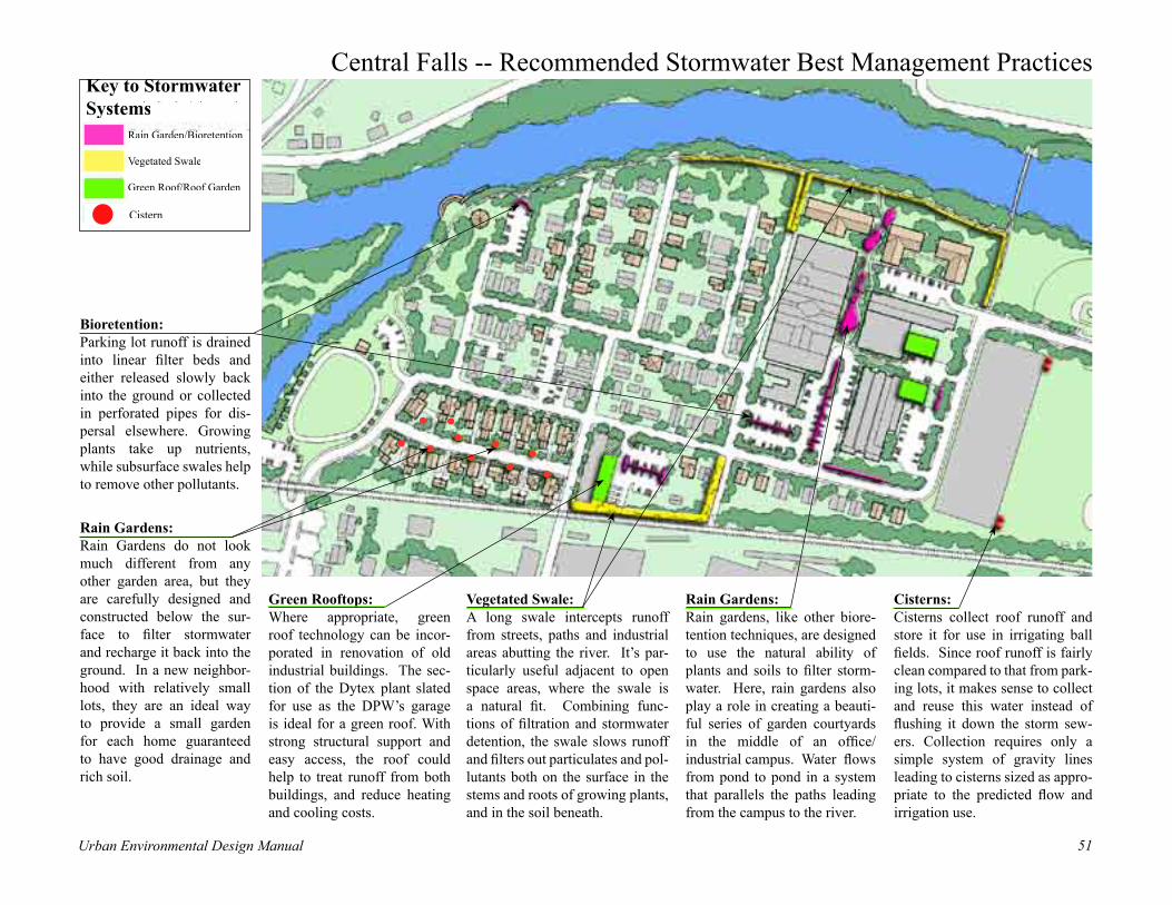
Urban Environmental Design Manual50 Urban Environmental Design Manual 51
Central Falls -- Recommended Stormwater Best Management Practices
Rain Gardens:Rain gardens, like other biore-tention techniques, are designed to use the natural ability of plants and soils to filter storm-water. Here, rain gardens also play a role in creating a beauti-ful series of garden courtyards in the middle of an office/industrial campus. Water flows from pond to pond in a system that parallels the paths leading from the campus to the river.
Rain Gardens:Rain Gardens do not look much different from any other garden area, but they are carefully designed and constructed below the sur-face to filter stormwater and recharge it back into the ground. In a new neighbor-hood with relatively small lots, they are an ideal way to provide a small garden for each home guaranteed to have good drainage and rich soil.
Bioretention: Parking lot runoff is drained into linear filter beds and either released slowly back into the ground or collected in perforated pipes for dis-persal elsewhere. Growing plants take up nutrients, while subsurface swales help to remove other pollutants.
Green Rooftops:Where appropriate, green roof technology can be incor-porated in renovation of old industrial buildings. The sec-tion of the Dytex plant slated for use as the DPW’s garage is ideal for a green roof. With strong structural support and easy access, the roof could help to treat runoff from both buildings, and reduce heating and cooling costs.
Vegetated Swale: A long swale intercepts runoff from streets, paths and industrial areas abutting the river. It’s par-ticularly useful adjacent to open space areas, where the swale is a natural fit. Combining func-tions of filtration and stormwater detention, the swale slows runoff and filters out particulates and pol-lutants both on the surface in the stems and roots of growing plants, and in the soil beneath.
Cisterns:Cisterns collect roof runoff and store it for use in irrigating ball fields. Since roof runoff is fairly clean compared to that from park-ing lots, it makes sense to collect and reuse this water instead of flushing it down the storm sew-ers. Collection requires only a simple system of gravity lines leading to cisterns sized as appro-priate to the predicted flow and irrigation use.
Key to Stormwater Key to Stormwater Systems
Rain Garden/BioretentionRain Garden/Bioretention
Vegetated Swale
Green Roof/Roof Garden
Constructed Wetland
Cistern
Key to Stormwater Key to Stormwater Systems
Rain Garden/BioretentionRain Garden/Bioretention
Vegetated Swale
Green Roof/Roof Garden
Constructed Wetland
Cistern
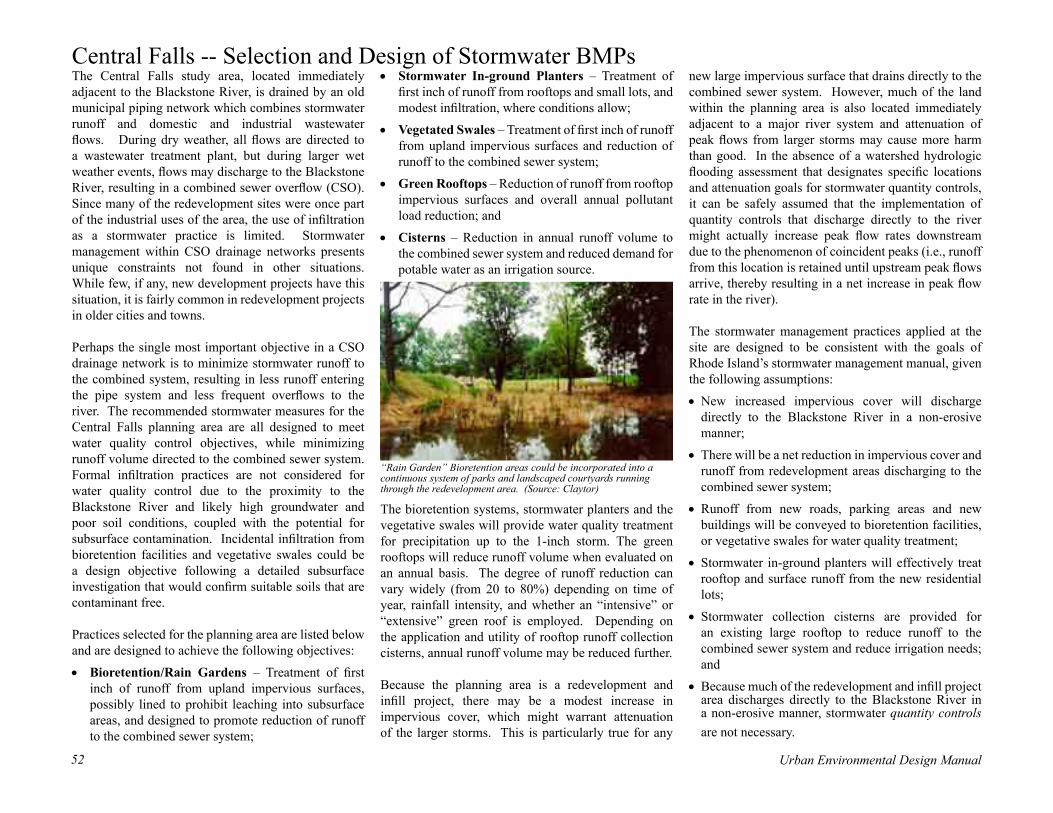
Urban Environmental Design Manual52 Urban Environmental Design Manual 53
new large impervious surface that drains directly to the combined sewer system. However, much of the land within the planning area is also located immediately adjacent to a major river system and attenuation of peak flows from larger storms may cause more harm than good. In the absence of a watershed hydrologic flooding assessment that designates specific locations and attenuation goals for stormwater quantity controls, it can be safely assumed that the implementation of quantity controls that discharge directly to the river might actually increase peak flow rates downstream due to the phenomenon of coincident peaks (i.e., runoff from this location is retained until upstream peak flows arrive, thereby resulting in a net increase in peak flow rate in the river).
The stormwater management practices applied at the site are designed to be consistent with the goals of Rhode Island’s stormwater management manual, given the following assumptions:
• New increased impervious cover will discharge directly to the Blackstone River in a non-erosive manner;
• There will be a net reduction in impervious cover and runoff from redevelopment areas discharging to the combined sewer system;
• Runoff from new roads, parking areas and new buildings will be conveyed to bioretention facilities, or vegetative swales for water quality treatment;
• Stormwater in-ground planters will effectively treat rooftop and surface runoff from the new residential lots;
• Stormwater collection cisterns are provided for an existing large rooftop to reduce runoff to the combined sewer system and reduce irrigation needs; and
• Because much of the redevelopment and infill project area discharges directly to the Blackstone River in a non-erosive manner, stormwater quantity controls are not necessary.
Central Falls -- Selection and Design of Stormwater BMPs The Central Falls study area, located immediately adjacent to the Blackstone River, is drained by an old municipal piping network which combines stormwater runoff and domestic and industrial wastewater flows. During dry weather, all flows are directed to a wastewater treatment plant, but during larger wet weather events, flows may discharge to the Blackstone River, resulting in a combined sewer overflow (CSO). Since many of the redevelopment sites were once part of the industrial uses of the area, the use of infiltration as a stormwater practice is limited. Stormwater management within CSO drainage networks presents unique constraints not found in other situations. While few, if any, new development projects have this situation, it is fairly common in redevelopment projects in older cities and towns.
Perhaps the single most important objective in a CSO drainage network is to minimize stormwater runoff to the combined system, resulting in less runoff entering the pipe system and less frequent overflows to the river. The recommended stormwater measures for the Central Falls planning area are all designed to meet water quality control objectives, while minimizing runoff volume directed to the combined sewer system. Formal infiltration practices are not considered for water quality control due to the proximity to the Blackstone River and likely high groundwater and poor soil conditions, coupled with the potential for subsurface contamination. Incidental infiltration from bioretention facilities and vegetative swales could be a design objective following a detailed subsurface investigation that would confirm suitable soils that are contaminant free.
Practices selected for the planning area are listed below and are designed to achieve the following objectives:
• Bioretention/Rain Gardens – Treatment of first inch of runoff from upland impervious surfaces, possibly lined to prohibit leaching into subsurface areas, and designed to promote reduction of runoff to the combined sewer system;
• Stormwater In-ground Planters – Treatment of first inch of runoff from rooftops and small lots, and modest infiltration, where conditions allow;
• Vegetated Swales – Treatment of first inch of runoff from upland impervious surfaces and reduction of runoff to the combined sewer system;
• Green Rooftops – Reduction of runoff from rooftop impervious surfaces and overall annual pollutant load reduction; and
• Cisterns – Reduction in annual runoff volume to the combined sewer system and reduced demand for potable water as an irrigation source.
The bioretention systems, stormwater planters and the vegetative swales will provide water quality treatment for precipitation up to the 1-inch storm. The green rooftops will reduce runoff volume when evaluated on an annual basis. The degree of runoff reduction can vary widely (from 20 to 80%) depending on time of year, rainfall intensity, and whether an “intensive” or “extensive” green roof is employed. Depending on the application and utility of rooftop runoff collection cisterns, annual runoff volume may be reduced further.
Because the planning area is a redevelopment and infill project, there may be a modest increase in impervious cover, which might warrant attenuation of the larger storms. This is particularly true for any
“Rain Garden” Bioretention areas could be incorporated into a continuous system of parks and landscaped courtyards running through the redevelopment area. (Source: Claytor)

Urban Environmental Design Manual52 Urban Environmental Design Manual 53
Stormwater BMPs as Landscape AmenitiesAs the science of designing and building stormwater facilities becomes more sophisticated, designers are beginning to explore the aesthetic potential of these elements in the landscape. If stormwater management is a necessary expense in the development and redevel-opment process, it only makes sense to maximize the benefit from that investment. Not only can this pro-duce BMPs that are cheaper to build and maintain, but it allows them to serve as valuable landscape amenities rather than mere plumbing.
With a little forethought, for example, barren rectangu-lar detention basins surrounded by chain link fencing can be naturalized and allowed to serve as a visual focus for surrounding buildings (above). While the natural approach can save on maintenance, the design-er needs to understand the way the plantings and the site will develop over time: through this understand-ing, maintenance can be minimized as the site is allowed to grow in and mature, gradually chang-ing but always attractive. Simplicity is often the key to creating beautiful natu-ral areas, (right), where design is based on simple forms and patterns repeat-ed in endlessly complex and fascinating ways.
Best Management Practices as Urban Design ElementsIntegrating Stormwater BMPs in New ParksPlanning for new parks, particularly on former indus-trial land, offers a wealth of possibilities to rebuild natural systems for storing, treating, and transporting stormwater. By studying the form and processes of natural wetlands and ponds, new ones can be created that fulfill many of the same functions. Of equal benefit to the design of public parks, “natural” ponds, streams and wetland systems offer unmatched aesthetic pos-sibilities.
The striking visual character of water and natural vegetation can be heightened by interweaving a chain of wetlands and ponds with a walking path leading to an overlook or gathering spot. Benches, decorative bridges, (right, above) viewing platforms or gazebos can be incorporated as amenities. Wetland-loving trees and shrubs can be used to frame views of water bodies and open lawns or meadow areas, creating a dramatic contrast in form and texture.
Perennial plantings can be used effectively to create a visual focus (right, below). An exciting aspect of work-ing with ponds and wetlands is that they provide habitat for an extraordinary range of shrubs and herbaceous pe-rennials that will not grow in an ordinary garden.
Like any natural ecosystem, a constructed wetland will change over time as flooded areas silt in and trees start to grow. This can be managed with yearly mowing
and occasional dredging, or al-lowed to proceed as part of the natural process. In any case, park users may have to get used to the sometimes messy aspect of wetlands in action. Interpretive displays, nature trails, and brochures can help to educate visitors about the complex functions and interest-ing ecology of streams, ponds and wetlands.
(Source: Claytor)
(Source: Center for Watershed Protection)
(Source: Comstock, Stewart)
(Source: Comstock, Stewart)

Urban Environmental Design Manual54 Urban Environmental Design Manual 55
Turning Hardscapes into GreenscapesFor dense urban sites, where space for structures, park-ing, and pedestrian circulation is at a premium, there may be little room for parklike amenities. Yet even here stormwater BMPs can be used to soften hard edg-es and introduce greenery. For example, grid pavers (below) help to slow runoff from the surface of parking areas, while allowing some water to infiltrate. Whether or not they contain growing plants such as the grasses illustrated here, the change in materials and patterns helps to reduce the visual impact of parking lots, while the lighter color and higher moisture levels reduces summer heat absorption.
In many of the urban redevelopment sites illustrated by the case studies, the mix of old and new buildings offers many opportunities for both “extensive” and “in-tensive” green roof systems. Both offer environmental benefits; just as important are the aesthetic benefits of flowers and greenery, especially in a densely developed site where so much of the land area is devoted to park-ing lots and buildings. Extensive roof systems, with a relatively thin layer of soil and vegetation, serve from an aesthetic standpoint primarily as a soft green sur-face. They reduce glare and provide a pleasing contrast to building materials Intensive green roof systems can allow a more traditional roof garden (right). Here, forms and materials are limited only by cost consider-ations and the bearing capacity of supporting structures. Design is often influenced by whether the garden will be viewed from above or experienced primarily from the surface level.
Courtyards that will be actively used by residents can be designed to include stormwater management func-tions (right). Careful layout of paths, terraces, and bench locations makes the most use of limited space and clearly separates private and public areas. Perma-nent plantings of trees, shrubs and hedges establish the structure of the garden and keep things tidy throughout the year. Within the garden beds, seasonal plantings vary from bulbs in the spring to summer annuals and perennials. The beds themselves have been carefully designed to act as bioretention areas, with layers of soil and gravel to absorb and filter runoff and hold it for gradual release, either directly into the ground or piped from the bottom of the bed to the larger stormwater system for the complex.
(Source: Portland, OR)
(Source: Portland, OR)

Urban Environmental Design Manual54 Urban Environmental Design Manual 55
Chapter 3 -- Best Management Practices for Urban SitesIntroductionThis chapter describes some of the key issues and selection criteria for Stormwater Best Management Practices. Its overall theme is that to manage both the large storms and pollutant loading usually requires a series of practices tailored to a particular site or modified based on the receiving waters. Factors to be considered include land use, physical constraints, watershed context, required capacity, pollutant removal needs, environmental benefits, and maintenance issues.
This chapter provides detailed descriptions of practices recommended for the four case study scenarios described in Chapter Three. These include both small-scale practices based on simple technologies like rain barrels, as well as more complex techniques such as green rooftop systems. Each includes a discussion of appropriate applications, costs, benefits and limitations, as well as design standards and maintenance requirements.
The practices described are:• Rain Barrels and Cisterns• Stormwater Planters• Permeable Paving• Open Channels• Stream Daylighting• Vegetated Buffers• Stormwater Wetlands• Bioretention• Green Rooftop Systems
Selecting Stormwater PracticesThe selection of appropriate stormwater practices for any given site involves a combination of the process of elimination and the process of addition. Typically, no single practice will meet all stormwater management objectives. Instead, a series of practices are generally required. Certain practices can be eliminated from consideration, based on one limiting factor. But several practices may ultimately “survive” the elimination process. The most appropriate practices are those that are both feasible, cost effective, and achieve the maximum benefits for watershed protection.
Structural stormwater practices are frequently designed to meet either water quality and/or water quantity control requirements. Water quality facilities are typically applied to control and treat pollutants that wash off urban land surfaces and are designed for a prescribed volume of runoff, which is usually relatively
small and is related to the so-called “first flush” of stormwater. The first flush is generally considered to be between the first half-inch of rainfall up to the first inch of rainfall and is significantly higher in pollutant concentrations than the stormwater from subsequent rainfall. Documented stormwater quality monitoring shows that, in most cases, the majority of contaminants that wash off the land surface will be carried away in the first flush of stormwater in any given storm. Therefore, stormwater treatment practices can remove the greatest proportion of contaminants by treating the first flush, which allows practices to be sized for a relatively modest volume of runoff. In Rhode Island, the one-inch of runoff from impervious surfaces is used as a basis for sizing water quality control facilities (RIDEM, 1993 or most recent addition “Stormwater Design and Installation Standards Manual).
Water quantity facilities are typically designed to control increases in peak flow rates and volumes associated with larger storms in the range of the 2-year frequency storm up to the 100-year storm. The 2-year frequency storm is defined as the precipitation amount that has a likelihood of occurring once every two years, or has a 50% chance of occurring in any given year. In Rhode Island, proposed projects must control and maintain post-development peak discharge rates from the 2-year and 25-year storm events at pre-development levels. In addition, a downstream analysis of the 100-year storm event is required to ensure no
Planners, engineers and municipal officials should check local, state and federal ordi-nances to ensure that project designs are in conformance with all applicable laws and regulations. In particular, stormwater man-agement is regulated by RIDEM and storm-water project designers and municipal staff should consult with RIDEM’s Stormwater Design and Installation Standards Manual for the latest specific criteria and procedures regarding stormwater system design.

Urban Environmental Design Manual56 Urban Environmental Design Manual 57
adverse impact at this precipitation value, and if impacts are evident, controls may be necessary.
The basic considerations for arriving at the most appropriate practice or suite of practices at any given site or project are typically governed by the following factors:
Land use.Which practices are best suited for the proposed land use at the site in question? Some practices are ill suited for certain land uses. For example, infiltration practices should not be utilized where runoff is expected to contain high levels of dissolved constituents, such as metals or hydrocarbons or where prior subsurface contamination is evident. Increased hydraulic loading to contaminated soils can accelerate pollutant migration and/or leaching into underlying groundwater.
Physical feasibility factors.Are there certain physical constraints at a project site that restrict or preclude the use of particular practices? This involves an assessment of existing onsite structures, soils, drainage area, water table, slope or elevation constraints at a particular site. For example, the rule-of-thumb minimum drainage area for constructed wetlands is 25-acres unless groundwater interception is likely. Constructed wetlands also can consume a significant land area.
Watershed factors.What watershed protection goals are needed within watershed that the site drains to? This set of factors involves screening out those practices that might contradict overall watershed protection strategies, or eliminating management requirements where they are unnecessary or inappropriate. For example, practices that maximize pollutant and toxicity reduction are typically relevant in urban watersheds such as the lower Blackstone and water quantity controls are not necessary for discharges to tidal waters or large river systems. Regulatory requirements under the Clean Water Act, Total Maximum Daily Load (TMDL) reduction requirements and/or interests from watershed associations may dictate the type, location, and design requirements for stormwater management practices.
Stormwater management control capability.What is the capability of a particular stormwater practice or suite of practices to meet the multiple objectives of water quality controls, and/or water quantity controls? Certain practices have limited capabilities to manage a wide range of storm frequencies. For example, the filtering practices are generally limited to water quality treatment and seldom can be utilized to meet larger storm stormwater management objectives.
Pollutant removal capability. How do each of the stormwater management options compare in terms of pollutant removal? Some practices have a better pollutant removal
potential than others or have a better capability to remove certain pollutants. For example, stormwater wetlands provide excellent total suspended solids (TSS) removal but only modest total nitrogen (TN) removal.
Environmental and maintenance considerations.Do the practices have important environmental benefits or drawbacks or a maintenance burden that might influence the selection process? Some practices can have significant secondary environmental impacts that might preclude their use in certain situations. Likewise, some practices have frequent maintenance and operation requirements that are beyond the capabilities of the owner. For example, infiltration practices are generally considered to have the highest maintenance burden because of a high failure history and consequently, a higher pre-treatment maintenance burden and/or replacement burden. Infiltration practices should not be used where prior subsurface contamination is present due to the increased threat of pollutant migration associated with increase hydraulic loading from infiltration systems.

Urban Environmental Design Manual56 Urban Environmental Design Manual 57
Rain Barrels & CisternsIntroduction
Rain barrels and cisterns are automatic water collection systems that store runoff from stormwater to be used later for activities such as lawn and garden watering. Reuse of stormwater runoff is beneficial to the environment because the stored water would otherwise enter the storm sewer, increasing the volume of discharge into receiving waters. In older cities, such as many in Rhode Island with combined sewer systems, the addition of stormwater also contributes to sanitary sewer overflows. Rain barrels are small barrels (50 to 250 gallons) placed on the end of a down spout that store runoff for future irrigation use (Figure 1). A cistern is similar to a rain barrel, but it has much greater storage capacity and can be designed to collect runoff from impervious
areas (roof and/or pavement), filter the water, store it, and use it for watering lawns and gardens. Cisterns can also be designed for household uses such as toilet flushing, and clothes washing (Figure 2).
The basic components of any rain barrel are relatively simple. Rain barrels consist of an actual barrel, often made of plastic, a sealed yet removable child and animal resistant top to keep potential pests out, connections to the downspout, a runoff pipe and a spigot. A number of accessories can be added, such as additional barrels for expanded storage volume,
a water diversion soaker hose, an automatic overflow, or an automatic irrigation overflow.
Cisterns can be constructed of any impervious, water-retaining material. They can be located either above or below ground and can be constructed on-site or pre-manufactured and then placed on-site. The basic components of a cistern include: a secure cover, a leaf/mosquito screen, a coarse inlet filter with clean-out valve, an overflow pipe, a manhole, a sump, a drain for cleaning, and an extraction system (tap or pump). Additional features might include a water level indicator, a sediment trap, or an additional tank for more storage volume.
Facility Application
Rain barrels and cisterns can be used in most areas (residential, commercial, and industrial) due to their minimal site constraints relative to other stormwater management practices. They
Figure 1-B. Rain BarrelSource: Claytor
Figure 1-A. Rain Barrel Source: www.rdrop.com
Figure 2-A. Cisterns Source: Chesapeake Bay Foundation

Urban Environmental Design Manual58 Urban Environmental Design Manual 59
can be applied to manage almost every land use type from very dense urban areas to more rural residential areas. The sizes of barrels or cisterns are directly proportional to their contributing drainage areas.
Benefits
Rain barrels and cisterns are low-cost water conservation devices that can reduce runoff volume for smaller storm events, and delay and reduce peak runoff flow rates. By storing and diverting runoff from impervious areas such as roofs, these devices reduce the undesirable impacts of runoff that would otherwise flow swiftly into receiving waters and contribute to flooding and erosion. Stored water from rain barrels and cisterns can help reduce domestic water consumption, which ultimately reduces the demand on municipal water systems and supplies.
Limitations
Rain barrels and cisterns are physically limited by their size. Once the rain barrels or cisterns are full, additional stormwater will overflow onto surrounding areas and/or into the downstream drainage system.
Sizing and Design Considerations
The sizing for rain barrels and cisterns is a function of the impervious area that drains to the device. The basic equation for sizing a rain barrel or a cistern is as follows:
Vol = A * R * 0.90 * 7.5 gals/ft3
where: Vol = Volume of rain barrel or cistern (gallons) A = Impervious surface area draining into barrel or cistern (ft2) R = Rainfall (feet) 0.90 = Loss to system (unitless) 7.5 = Conversion factor (gallons per cubic foot)
A cistern can be located beneath a single downspout or one large cistern can be located such that it collects stormwater from several sources. Due to the size of rooftops and the amount of contributing impervious area, increased runoff volume and peak discharge rates for commercial and industrial sites may require large capacity cisterns. Cisterns can be located above or below ground, and can be constructed on site or pre-manufactured and then placed on site. Cistern sizes can vary from hundreds of gallons for residential uses to tens of thousands of gallons for commercial and/or industrial uses.
Figure 2-B. CisternSource: Portland Stormwater Management Manual
Figure 2-C. CisternSource: Texas Guide to Rainwater Harvesting, Texas Water Development Board, Austin, TX

Urban Environmental Design Manual58 Urban Environmental Design Manual 59
Cost
Rain barrels are relatively low cost, pre-manufactured systems averaging about $120, minus downspout and other accessories (UGRC). Basic supplies to construct a barrel can be as low as $20. The cost for cisterns can vary greatly depending on its size, material and location (above or below ground). The following are representative costs for pre-manufactured cisterns, not including labor and accessory costs (Table 1).
Maintenance
Maintenance requirements for rain barrels and cisterns are minimal and consist of bi-annual inspections of the unit. The following components should be inspected and either repaired or replaced as needed (Table 2).
ReferencesKessner, K., 2000. How to Build a Rainwater Catchment Cistern. The March Hare, Summer 2000, Issue 25, http://www.dancingrabit.org/newletter/
Low Impact Development Center, Inc. (LID)h t tp : / /www. l i d - s to rmwa te r. ne t / i n t ro /sitemap.htm#permpavers
The Urban Garden Rain Center (UGRC), Rain barrel Web page, www.urbangarden.com
Table 1: Cost Guide – Pre-manufactured Cisterns (LID)
Material Cost, Small System Cost, Large SystemGalvanized Steel $225 for 200 gallons $950 for 2,000 gallons
Polyethylene $160 for 165 gallons $1,100 for 1,800 gallonsFiberglass $660 for 350 gallons $10,000 for 10,000 gallons
Fiberglass/Steel Composite $300 for 300 gallons $10,000 for 5,000 gallons
The average cost for a typical manually-constructed cistern for residential use made of reinforced concrete (3,000 gallons), minus labor, would be approximately $1,000 (Kessner, 2000).
Table 2: Maintenance of Rain Barrels and Cisterns (LID)
Rain Barrels CisternsRoof Catchment – ensure that no particulate matter or other parts of the roof are entering the gutter and downspout to the rain barrel.
Roof Catchment –ensure that no particulate matter or other parts of the roof are entering the gutter and downspout to the cistern.
Gutters – ensure that no leaks or obstructions are occurring.
Gutters – ensure that no leaks or obstructions are occurring.
Downspouts – ensure that no leaks or obstructions are occurring.
Downspouts – ensure that no leaks or obstructions are occurring.
Entrance at Rain Barrel – ensure that no leaks or obstructions are occurring.
Roof Washer and Cleanout Plug – inspection and replacement as needed.
Rain Barrel – check potential leaks, including barrel top and seal.
Cistern Screen - inspection and replacement as needed.
Runoff/Overflow Pipe – check that overflow is draining in non-erosive manner.
Cistern Cover - inspection and replacement as needed.
Spigot – ensure that it is functioning correctly. Cistern – inspection and cleanout, should include inflow and outflow pipes.
Any accessories – such as rain diverter, soaker hose, linking kit or additional gutters.
Cistern Overflow Pipe - inspection and replacement as needed.
Any accessories – inspection and replacement as needed, such as sediment trap.

Urban Environmental Design Manual60 Urban Environmental Design Manual 61
Stormwater PlantersIntroduction
Stormwater planters are small-scale, stormwater treatment systems comprised of organic soil media and plants in a confined planter box. Stormwater planters are simply “bioretention in-a-box” (see section on bioretention, page 88). Planters generally look like large vaulted plant boxes and can contain anything from basic wildflower communities to complex arrangements of trees and flowering shrubs. The method combines physical filtering and adsorption with bio-geochemical processes to remove pollutants.
There are three basic variations of the stormwater planters: the contained system, the
infiltration system, and the flow-through system. Contained planters are typical large self-contained planters found on terraces, desks and sidewalks (Figure 1). Infiltration planter boxes are designed to allow runoff to filter through the planter soils and then infiltrate into the native soils (Figure 2). Flow-through planter boxes are designed with impervious bottoms or placed on impervious surfaces. This flow-through system consists of an inflow component (usually a downspout), a treatment element (soil medium), an overflow structure, plant materials, and an underdrain collection system to divert treated runoff back into the downstream drainage system (Figure 3).
Facility Application
Stormwater planters are ideally adapted for ultra-urban redevelopment projects (Figure 4). Roof runoff can be directed from the downspout directly into the planters. Runoff from rooftop areas contains nutrients carried in rainwater, sediments and dust from rooftops, and bacteria
from bird traffic. These pollutants can all be attenuated to a significant degree during small rain events. Planters can be effective in reducing the velocity and volume of stormwater discharge from rooftops areas. Another benefit of stormwater planters is the relatively low cost. These are small self-contained units that can be easily constructed without heavy-duty excavation that accompanies other BMPs. Stormwater planters also add aesthetic elements by improving the surrounding streetscape
These systems are rarely used to manage large storms. Any storm greater than the infiltration capacity of the soil will flood the planters and will overflow onto the street or into an overflow
Figure 1: Contained PlanterSource: Chicago City Hall, (American Society of Landscape Architects, asla.org)
Figure 2: Infiltration Planter Source: City of Portland, Stormwater Management Manual, 2002

Urban Environmental Design Manual60 Urban Environmental Design Manual 61
pipe. Planters should be designed to attenuate water no more than 3 to 4 hours after an average storm. The topsoil (soil medium) should have an infiltration rate of 2 inches per hour. The drainage layer (sand or gravel) should have a minimum infiltration rate of 5 inches per hour.
Infiltration planters are also known as “exfilters”. An exflter is a system designed to filter runoff through the soil media before infiltration into the underlying soil (Figure 1). If poor soils, high groundwater, or soil contamination exists that would prevent conventional infiltration, then a contained or a flow-through stormwater planter is recommended.
Benefits
Stormwater planters can have many benefits when applied to redevelopment and infill projects in urban centers. The most notable benefits include:
• Effective pollutant treatment for solids, metals, nutrients and hydrocarbons
• Groundwater recharge augmentation (if designed as an exfilter, where soils, land uses, and groundwater elevations permit)
• Micro-scale habitat • Aesthetic improvement to otherwise
hard urban surfaces• Ease of maintenance, coupling routine
landscaping maintenance with effective stormwater management control
• Relatively low cost relative to other practices
Limitations
The application of stormwater planters is limited to treating only roof runoff. It is also limited in the amount of runoff it can receive. Infiltration and flow through planter boxes should receive drainage from no more than 15,000 square feet of impervious area. Any storm event greater than 2 inches per hour (topsoil infiltration rate) will start to pond in the planters and eventually overflow, onto the street or into the underdrain system and therefore will not be treated for water quality.
Sizing and Design Considerations
The basis for this guideline relies on the principles of Darcy’s Law, where liquid is passed through porous media with a given head, a given hydraulic conductivity, over a given timeframe. The basic equation for sizing stormwater planters is as follows:
Figure 3: Flow-through Planter, Source: City of Portland, Stormwater Management Manual, 2002
Urban Environmental Design Manual62 Urban Environmental Design Manual 63
Af = Vol*(df) / [k*(hf +df)(tf)]
where: Af = the required surface area (ft2) Vol = the treatment volume (ft3) df = depth of the soil medium (ft) k = the hydraulic conductivity (in ft/day, usually set at 4 ft/day, but can be varied depending on the properties of the soil media) hf = average height of water above the planter bed (maximum 12 inches) tf = the design time to filter the treatment volume through the filter media (usually set at 3 to 4 hours)
In addition, there are several physical geometry recommendations that should be considered in the layout and design of stormwater planters. The following design guidance is suggested:
• Minimum width: 1.5 feet (flow through planters) 2.5 feet (infiltration planters)
• Minimum length: none• Maximum ponding depth: 12 inches• Minimum building offset: 10 feet
(applies to infiltration planters only)
Stormwater planters rely on successful plant communities to create the micro-environmental conditions necessary to replicate the functions of a forested eco-system. To do that, plant species need to be selected that are adaptable to the wet/dry conditions that will be present
CostStormwater planters are cost-effective measures designed to help meet many of the management objectives of watershed protection. An example cost estimate for a proprietary flow-through-system is approximately $24,000 per acre of impervious surface (LID). Annual maintenance cost is approximately 2% to 8% of the system cost or in the range of $200 to $2,000 per impervious acre treated.
Maintenance
Inspections are an integral part of system maintenance. During the six months immediately after construction, planters should be inspected at least twice, and following precipitation events of at least 0.5 inches to ensure that the system is functioning properly. Thereafter, inspections should be conducted on an annual basis and after storm events of greater than or equal to the 1-year precipitation event (approximately 2.6 inches in Rhode Island). Minor soil erosion gullies should be repaired when they occur. Pruning or replacement of woody
Figure 4: Photo of an Infiltration PlanterSource: City of Portland, Stormwater Management Manual, 2002
vegetation should occur when dead or dying vegetation is observed. Herbaceous perennials should be divided when over-crowding is observed, or approximately once every 3 years.
References
City of Portland, 2002. “Stormwater Management Manual”. Environmental Services, Clean River Works.
Low Impact Development Center, Inc. (LID)h t tp : / /www. l i d - s to rmwa te r. ne t / i n t ro /sitemap.htm#permpavers

Urban Environmental Design Manual62 Urban Environmental Design Manual 63
Figure 1: Examples of Different Types of Permeable Paving, Source: City of Portland, Stormwater Management Manual, 2002
Permeable PavingIntroduction
Permeable paving is a broadly defined group of pervious types of pavements used for roads, parking, sidewalks and plaza surfaces. It is designed to infiltrate stormwater runoff through its surface, thereby reducing runoff from a site. In addition, permeable paving reduces impacts of impervious cover by infiltrating more precipitation, augmenting the recharge of groundwater, and enhancing pollutant uptake removal in the underlying soils. Due to the potential high risk of clogging the underlying soils, which would minimize recharge and pollutant removal, the use of permeable paving is restricted in its use.
There are many different types of permeable paving, for example:
• Concrete grid pavers• Lattice style paving that includes grass in
spaces in between lattice work• Porous pavement that looks like regular
pavement (asphalt or concrete) but is manufactured without “fine” materials
• Cobblestone• Brick• Plastic modular blocks• Crushed aggregate or gravel
Facility ApplicationThe ideal application for permeable paving is to treat low traffic roads (i.e. a few houses or a small cul-de-sac), overflow parking areas, sidewalks, plazas and courtyard areas. Permeable paving is intended to capture and manage small frequent rainfall events. These events can add up to as much as 30 – 50% of annual precipitation (Schueler, 1987). The system does not readily work for storms greater than 1-inch or with high rainfall intensities. The practice can be applied to manage almost every land use type from very dense urban areas to more rural residential areas. Major limitations to this practice are suitability of the grades, subsoils, drainage characteristics, and groundwater conditions.
For plazas and courtyard areas, vegetated infiltration trenches (“rain gardens”) can also be used. These are primarily a gravel or sand base for infiltration with selected planting materials
for aesthetics and some nutrient uptake. Like all other permeable paving types, the same limitations apply to this practice.
BenefitsPermeable paving can have many benefits when applied to redevelopment and infill projects in urban centers. The most notable benefits include:• Groundwater recharge augmentation;• Effective pollutant treatment for solids,
metals, nutrients and hydrocarbons (see pollutant removal performance, Table 1);
• Aesthetic improvement to otherwise hard urban surfaces (lattice pavers);
Two long-term monitoring studies conducted in Rockville, MD, and Prince William, VA indicated high removal efficiencies for sediments, nutrients, metals and chemical oxygen demand. (Table 1)
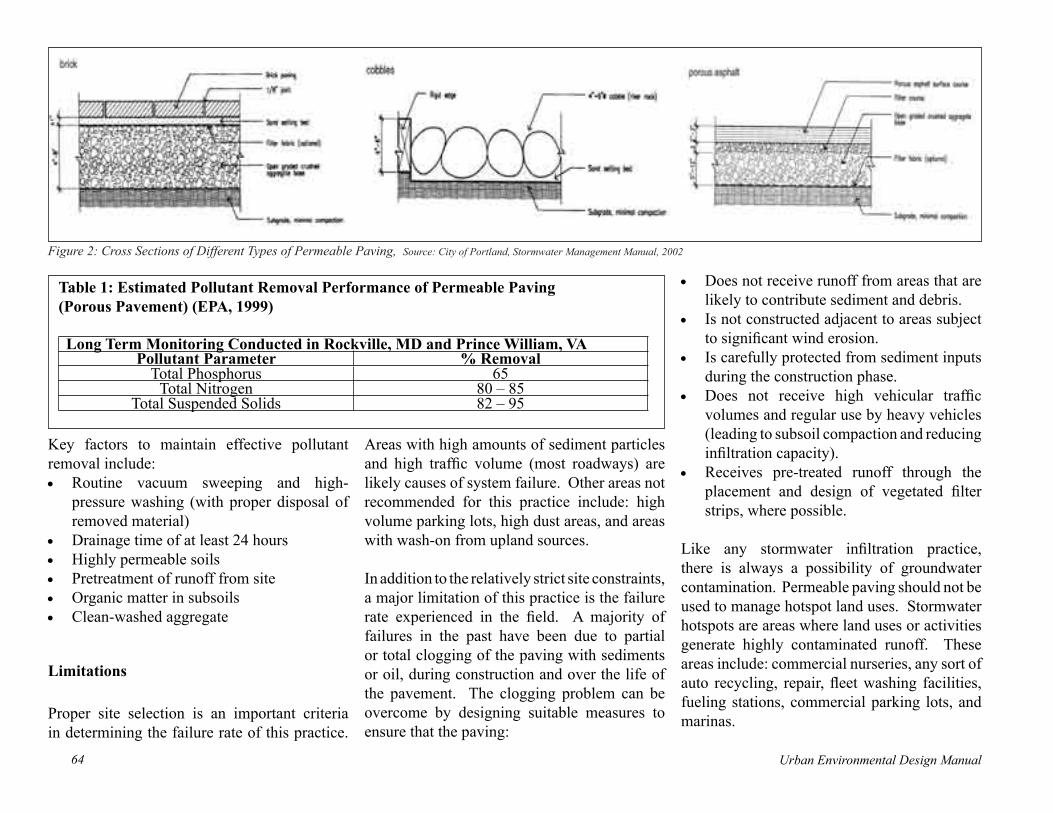
Urban Environmental Design Manual64 Urban Environmental Design Manual 65
Figure 2: Cross Sections of Different Types of Permeable Paving, Source: City of Portland, Stormwater Management Manual, 2002
Table 1: Estimated Pollutant Removal Performance of Permeable Paving (Porous Pavement) (EPA, 1999)
Long Term Monitoring Conducted in Rockville, MD and Prince William, VAPollutant Parameter % Removal
Total Phosphorus 65Total Nitrogen 80 – 85
Total Suspended Solids 82 – 95
Key factors to maintain effective pollutant removal include:• Routine vacuum sweeping and high-
pressure washing (with proper disposal of removed material)
• Drainage time of at least 24 hours• Highly permeable soils• Pretreatment of runoff from site• Organic matter in subsoils• Clean-washed aggregate
Limitations
Proper site selection is an important criteria in determining the failure rate of this practice.
Areas with high amounts of sediment particles and high traffic volume (most roadways) are likely causes of system failure. Other areas not recommended for this practice include: high volume parking lots, high dust areas, and areas with wash-on from upland sources.
In addition to the relatively strict site constraints, a major limitation of this practice is the failure rate experienced in the field. A majority of failures in the past have been due to partial or total clogging of the paving with sediments or oil, during construction and over the life of the pavement. The clogging problem can be overcome by designing suitable measures to ensure that the paving:
• Does not receive runoff from areas that are likely to contribute sediment and debris.
• Is not constructed adjacent to areas subject to significant wind erosion.
• Is carefully protected from sediment inputs during the construction phase.
• Does not receive high vehicular traffic volumes and regular use by heavy vehicles (leading to subsoil compaction and reducing infiltration capacity).
• Receives pre-treated runoff through the placement and design of vegetated filter strips, where possible.
Like any stormwater infiltration practice, there is always a possibility of groundwater contamination. Permeable paving should not be used to manage hotspot land uses. Stormwater hotspots are areas where land uses or activities generate highly contaminated runoff. These areas include: commercial nurseries, any sort of auto recycling, repair, fleet washing facilities, fueling stations, commercial parking lots, and marinas.

Urban Environmental Design Manual64 Urban Environmental Design Manual 65
Sizing and Design GuidancePermeable paving areas are usually designed to accommodate a design storm of 1-inch. Storms greater than that will either sheet flow off the site, or if not graded properly, will pond on the site. Potential permeable paving sites need to be evaluated for the following criteria:• Soils need to have a permeability between
0.5 and 3.0 inches per hour (up to 8.3 inches for sand).
• The bottom of the stone reservoir should not exceed a slope of 5 percent. Ideally it should be completely flat so that the infiltrated runoff will be able to infiltrate through the entire surface.
• Permeable paving should be located at least 2 feet above the seasonally high groundwater table, and at least 100 feet away from drinking water wells.
• Permeable paving should be located in low traffic and overflow parking areas.
• The contributing drainage area should be less than 15 acres.
Infiltration practices shall be designed to exfiltrate the water quality volume through the floor of each practice.
Calculate the surface area of infiltration trenches as:
Ap = Vw / (ndt + fT/12)
where:Ap = surface area (f2)Vw = design volume (e.g., WQv) (ft
3)n = porosity (assume 0.4)dt = trench depth (maximum of seven feet, and separated by at least three feet from seasonally high groundwater) (ft)fc = infiltration rate (in/hr)T = time to fill trench or dry well (hours) (generally assumed to be less than 2 hours)
Cost
Costs for permeable paving are significantly more than traditional pavement (Table 2). However, incorporating savings from not having to build a separate stormwater infrastructure in addition to paving, the overall project costs are reduced.
Table 2: Cost Guides for Permeable Pavement System (LID)
Paver System Cost Per Square Foot (Installed)Asphalt $0.50 to $1.00Porous Concrete $2.00 to $6.50Grass/gravel pavers $1.50 to $5.75Interlocking Concrete Paving Blocks $5.00 to $10.00
The estimated annual maintenance cost for a porous pavement parking lot is $200 per acre per year (EPA, 1999). This cost assumes four inspections each year with appropriate jet hosing and vacuum sweeping.
Maintenance
Depending on the type of permeable paving and the location of the site, the maintenance level ranges from high to low. Areas that receive high volume of sediment particles will clog more readily due to soil compaction. Concrete grid pavers and plastic modular blocks require less maintenance because they are not clogged by sediment as easily as porous asphalt pavement. However, regardless of the type of pavers used, the level of maintenance and ultimately the failure rate is dependent on the location of the site. Properly selected sites with permeable paving normally require regular vacuum sweeping or high pressure hosing once every three months to remove sediments. Typical maintenance activities for porous pavement are summarized below (Table 3).

Urban Environmental Design Manual66 Urban Environmental Design Manual 67
Table 3: Typical Maintenance Activities for Porous Pavement (WMI, 1997)
Activity ScheduleEnsure that paving area is clean of debris Monthly
Ensure that paving dewaters between storms MonthlyEnsure that the area is clean of sediments Monthly
Mow upland and adjacent areas, and seed bare areas As neededVacuum sweep frequently to keep surface free of sediments
(Typically 3 to 4 times a year) As neededInspect the surface for deterioration or spalling Annual
References
Center for Watershed Protection (CWP), 2002. The Vermont Stormwater Manual. Vermont Agency of Natural Resources. Waterbury, VT.
Low Impact Development Center, Inc. (LID)h t tp : / /www. l i d - s to rmwa te r. ne t / i n t ro /sitemap.htm#permpavers
Schueler, T.1987. Controlling Urban Runoff: A Practical manual for Planning and Designing Urban BMPs. Metropolitan Washington Council of Governments. Washington, DC
United States Environmental Protection Agency (EPA), “Storm Water Technology Fact Sheet, Porous Pavement”, September 1999.
Watershed Management Institute (WMI). 1997. Operation, Maintenance, and Management of Stormwater Management Systems. Prepared for: US EPA Office of Water. Washington, DC.

Urban Environmental Design Manual66 Urban Environmental Design Manual 67
Figure 1-B: Schematic of Different Open Channel SystemsSource: Claytor & Schueler, 1996
Figure 1-A (above and far right): Photos of Different Open Channel Systems(Source: City of Portland, Stormwater Management Manual, 2002)
Open ChannelsIntroduction
Open channels are concave, vegetated conveyance systems that can improve water quality through infiltration and filtering. When designed properly, they can be used to retain and pre-treat stormwater runoff. There are four different categories of open channels used in stormwater management practices. These include: drainage channels, grass channels (“biofilters”), dry swales and wet swales (Figure 1-A & 1-B).
Drainage channels have minimal or no stormwater pre-treatment capabilities. They are designed primarily to transport stormwater on the land surface. Grass channels are modified drainage channels that provide water quality treatment for the small, frequent storm events. The flow rate is the principle design criteria
for grass channels (“rate-based” system). Dry swales have the same principle pre-treatment process as bioretention filters (see section on bioretention, page 86) which combines physical filtering and adsorption with bio-geochemical processes to remove pollutants. Dry swales are designed to rapidly dewater through a highly permeable layer and then collected by an underdrain pipe. Wet swales act as long, linear shallow wetland treatment systems. Wet swales occur when the water table is located very close to the surface. Dry/Wet swales are designed to treat or retain stormwater for a 24-hour period (“volume-based” systems).

Urban Environmental Design Manual68 Urban Environmental Design Manual 69
Figure 2A: Schematic Plan of a Grass Channel Source: Claytor & Schueler, 1996
Figure 3-A (above and far right): Photos of Dry SwalesSource: Claytor
Figure 2B: Profile/Cross-Section of a Grass ChannelSource: Claytor & Schueler, 1996
Source: Claytor
Facility Application
Grass channels and dry/wet swales are rarely used to manage large storms or to provide peak flow attenuation for the so-called “channel forming” storms (i.e, in the range of the 1-year to 1.5-year frequency return interval), or flood control events (i.e., 10-year to 100-year frequency return intervals).
Grassed channels accent the natural landscape, break up impervious areas, and are appropriate alternatives to curb and gutter systems (Figure 2). They are best suited to treat runoff from rural or very low density areas and major roadway and highway systems. They are often used in combination with other stormwater management practices to provide pre-treatment and attenuation, but can be used as stand-alone practices. The design objective for grass channels is to maintain a low flow rate in order to achieve a minimum residence time of ten minutes. A key factor in the suitability of grass channels designed for infiltration is the on-site
soils characteristics. Grass channels have the same design criteria as applied to infiltration basins and trenches: soil type, infiltration rate and separation to groundwater and bedrock.
Dry swales are appropriate in areas where standing water are not desirable such as residential, commercial, industrial areas and highway medians. In dry swales, a prepared soil bed is designed to filter the runoff for water
quality (Figure 3). Runoff is then collected in an underdrain system and is discharged to the downstream drainage system. The design objective for dry swales is to drain down between storm events within twenty-four hours.
Wet swales are similar to stormwater wetlands in their use of wetland vegetation to treat stormwater runoff (Figure 4). The water

Urban Environmental Design Manual68 Urban Environmental Design Manual 69
Figure 3-B: Plan and Section of Dry Swale, Source: Claytor & Schueler, 1996Figure 4: Schematic and Photo of a Wet SwaleSource: Claytor & Schueler, 1996
quality treatment mechanism relies primarily on settling of suspended solids, adsorption, and uptake of pollutants by vegetative root systems (Claytor & Schueler, 1996). Wet swales are designed to retain runoff for 24 hours. The application of wet swales are limited due to standing water and the potential problems associated with it such as safety hazards, odor, and mosquitoes.
The feasibility of installing any open channel on a site depends on the local climate, the right soils to permit the establishment and maintenance of a dense vegetative cover, and available area. The contributing area, slope,

Urban Environmental Design Manual70 Urban Environmental Design Manual 71
Source: Claytor
and perviousness of the site will determine the dimension and slope of the open channels.
Benefits
The benefits of open channel systems include minimized water balance disruptions through the reduction of peak flows, the filtering and adsorption of pollutants, and increased recharge. Other benefits include lower capital cost relative to a more structural stormwater management practices, more aesthetically pleasing because they accent the natural landscape and break up impervious areas, and a net benefit to the public in the reduction of urban heat island effect.
Table 1: Estimated Pollutant Removal Performance of Open Channels
Grass Channel 1 Dry Swale 2 Wet Swale 2
Pollutant Parameter % Removal % Removal % RemovalTotal Phosphorus 9 65 20Total Nitrogen NA 50 40Total Suspended Solids 81 90 80Nitrate 38 80 50Oxygen Demanding Substances 67 NA NAHydrocarbons 62 NA NACadmium 42 NA NACopper 51
80 - 90 40-70Lead 67Zinc 71
Note:1 – United States Environmental Protection Agency, 19992 - Claytor and Schueler, 1996
Limitations
Open channels used in stormwater management are typically ineffective for water quality treatment and are vulnerable during large storm events. High velocity flows as a result of these large storm events can erode the vegetative cover, if the channels or swales are not designed properly. Other limitations include:• Areas with very flat grades, steep
topography, and wet or poorly drained soils.
• Wet swales are potential drowning hazards, mosquito breeding areas, and may emit odor.
• The land space required for open channels ranges from 6.5 percent of total contributing impervious area for grass channels and 10 to 20 percent for dry and wet swales
(Claytor and Schuler, 1996).• Pre-treatment is necessary to extend the
practice’s functional life, as well as to increase the pollutant removal capability. A shallow forebay at the initial inflow point is recommended as a pre-treatment component.
Sizing and Design Guidance
The general design of open channel systems should take into consideration the following criteria (also summarized in Table 2):
• Soils – for grass channels, the infiltrating capability is a factor in locating swales. Swale infiltration rates measured in the field should be between 0.5 and 5.0 inches

Urban Environmental Design Manual70 Urban Environmental Design Manual 71
per hour. Suitable soils include sand, sandy loam, loamy sand, loam and silty loam. Highly permeable soils provide little treatment capability and soils with low permeability do not provide adequate infiltration during the short retention time. The soil bed underneath the dry swale should consist of a moderately permeable soil material, with a high level of organic matter.
• Shape – Open channel systems are usually parabolic or trapezoidal in shape. Parabolic swales are natural and are less prone to meander under low flow conditions. Trapezoidal swales provide additional area for infiltration but may tend to meander at low flows and may revert to a parabolic form. Trapezoidal sections should be checked against the parabolic sizing equation as a long-term functional assessment.
• Dimension – for grass channels, the side slopes in the channel should be 3:1 or flatter. The longitudinal slope should be between 1 and 4 percent for grass channels and 1 and 2 percent for dry and wet swales. The minimum length of a grass channel to ensure water quality treatment is 600 feet. This is determined based on the maximum flow velocity of 1 foot per second (fps) for water quality treatment, multiplied by a minimum residence time of 10 minutes (600 seconds). The wet swale length, width, depth, and slope should be designed to temporarily accommodate the water quality volume through surface ponding.
For a dry swale, all of the surface ponding should dissipate within a maximum 24-hour duration.
• Vegetative Cover – Dense vegetative cover slows the flow of water through the swale and increases treatment. Vegetation should be able to tolerate being wet for 24 hours. The velocities in the open channel systems should not exceed the erosive levels for the vegetative cover in the channel.
Table 2: Design Criteria for Open Channel Systems (Claytor and Schueler, 1996)
Parameter Design CriteriaGrass Channel Dry and Wet Swale
Bottom Width 2 feet minimum, 6 feet maximum2 feet minimum, 8 feet maximum widths up to 16 feet are allowable if a dividing berm or structure is used
Side Slopes 3:1 (horizontal:vertical) 2:1 maximum, 3:1 or flatter preferredLongitudinal
Slope 1.0% minimum, 4.0% maximum 1.0% to 2.0% without check dams
Flow Depth and Capacity 4 inches for water quality treatment
Surface storage of water quality volume with a maximum depth of 18 inches for water quality treatment (12 inches average depth). Adequate capacity for 10 year storm with 6 inches of freeboard
Manning’s n Value
0.15 for water quality treatment (depths ≤ 4 inches) varies from 0.15 to 0.03 for depth between 4 and 12
inches and 0.03 minimum for depths ≥12 inches
Flow Velocity1.0 fps for water quality treatment
4.0 fps to 5.0 fps for 2 year storm7.0 fps for 10 year storm
4.0 fps to 5.0 fps for 2 year storm
Length Length necessary for 10 minute residence time
Length necessary to drain (dry swale) and retain (wet swale) runoff for 24 hours
Once runoff rates and volumes are calculated using an appropriate hydrologic model, the basic equation for sizing open channel systems are summarized below (Table 3).

Urban Environmental Design Manual72 Urban Environmental Design Manual 73
Table 3: Design Equations for Open Channel Systems
Grass Channel Dry Swales Wet SwalesEquation Equation Equation
V = (1.49/n)R2/3 S1/2 Af = Vol*(df) / [k*(hf +df)(tf)]
Vol = A x LR = A / PVariables Variables Variables
V Velocity, should be less than 1 ft/sec Af
Required surface area of the dry swale (ft2) Vol Retention volume
(ft3)
n Roughness coefficient (tabulated values) Vol Treatment volume
(ft3) A Cross sectional area (ft2)
R Hydraulic radius (ft) dfDepth of the filter
medium (ft) L Length of swale (ft)
A Cross sectional area (ft2) k Hydraulic
conductivity (ft/day)
P Wetted perimeter (ft) hf
Average height of water above the
bottom of dry swale (ft)
S Longitudinal slope tf
Design time to filter the treatment volume
through the filter media (usually set at
24 hours)
CostOpen channel systems are cost-effective measures relative to curb and gutter systems and underground storm sewers. The base cost for grass channels is 25 cents per square foot (SWRPC, 1991). Designed swales, such as a dry swale with prepared soil and underdrain piping has an estimated cost of $4.25 per cubic foot (SWRPC, 1991). Relative to other filtering system options, these costs are considered to be
Maintenance
The life of an open channel system is directly proportional to its maintenance frequency. The maintenance objective for this practice includes keeping up the hydraulic and removal efficiency of the channel and maintaining a dense, healthy grass cover. The following activities are recommended on an annual basis or as needed:• Mowing and litter and debris removal• Stabilization of eroded side slopes and
bottom• Nutrient and pesticide use management• Dethatching swale bottom and removal of
thatching • Discing or aeration of swale bottomEvery five years,the channel bottom may need reshaping and removal of sediment to restore original cross section and infiltration rate, and seeding or sodding to restore ground cover is recommended.
Maintenance for the grass channel consists of annual inspections and correction of erosion gullying and reseeding as necessary. When sediment accumulates to a depth of approximately 3 inches, it should be removed and the swale should be reconfigured to its original dimensions. The grass in the swale should be mowed at least 4 times during the growing season. The condition of the grass vegetation should be noted during inspection and repaired as necessary.
moderate to low. Most recent cost estimates have approximated $5 per linear feet for grass channels and $19 per linear feet for dry swales. The annual maintenance cost can range from 5 to 7 percent of the construction cost (SWRPC, 1991).

Urban Environmental Design Manual72 Urban Environmental Design Manual 73
Dry Swales should be inspected on an annual basis and just after storms of greater than or equal to the 1-year frequency storm . Both the structural and vegetative components should be inspected and repaired. When sediment accumulates to a depth of approximately 3 inches, it should be removed and the swale should be reconfigured to its original dimensions. The grass in the dry swale should be mowed at least 4 times during the growing season. If the surface of the dry swale becomes clogged to the point that standing water is observed in the surface 48 hours after precipitation events, the bottom should be roto-tilled or cultivated to break up any hard-packed sediment, and then reseeded. Trash and debris should be removed and properly disposed of.
Wet swales should be inspected annually and after storms of greater than or equal to 2.8 inches of precipitation. During inspection, the structural components of the pond, including trash racks, valves, pipes and spillway structures, should be checked for proper function. Any clogged openings should be cleaned out and repairs should be made where necessary. The embankments should be checked for stability and any burrowing animals should be removed. Vegetation along the embankments, access road, and benches should be mowed annually. Woody vegetation along those surfaces should be pruned where dead or dying branches are observed, and reinforcement plantings should be planted if less than 50 percent of the original vegetation establishes after two years. Sediment should be
removed from the bottom of the swale.
ReferencesClaytor and Schueler, 1996. Design of Stormwater Filtering Systems. for the Chesapeake Research Consortium. Center for Watershed Protection, Ellicott City, Maryland. 179 pp.
United States Environmental Protection Agency, “Storm Water Technology Fact Sheet, Vegetated Swales”, September 1999.
Southeastern Wisconsin Regional Planning Commission (SWRPC). 1991. Costs of Urban Nonpoint Source Water Pollution Control Measures. Waukesha, WI.

Urban Environmental Design Manual74 Urban Environmental Design Manual 75
Stream Daylighting
Introduction
Stream daylighting involves uncovering a stream or a section of a stream that had been artificially enclosed in the past to accommodate development. The original enclosure of rivers and streams often took place in urbanized areas through the use of large culvert operations that often integrated the storm sewer system and combined sewer overflows (CSO’s). The daylighting operation, therefore often requires overhauls or updating of storm drain systems and re-establishing stream banks where culverts once existed. When the operation is complete, what was once a linear pipe of heavily polluted water can become a meandering stream with dramatic improvements to both aesthetic and water quality. In some cases, instead of creating a natural channel for the daylighted stream, the culvert is simply replaced with a concrete channel.
Aside from water quality and general aesthetic improvements, stream daylighting can play an integral role in neighborhood restoration and site redevelopment efforts. Aside from improvements to infrastructure, stream daylighting can restore floodplain and aquatic habitat areas, reduce runoff velocities and be integrated into pedestrian walkway or bike path design.
Applicability of Practice
Stream daylighting can generally be applied most successfully to sites with considerable open or otherwise vacant space. This space is required to: 1) Potentially reposition the stream in its natural stream bed; 2) Accommodate the meandering that will be required if a natural channel is being designed; and 3) Provide adjacent floodplain area to store water in large storm flow situations. However, where a concrete channel will replace a culverted stream, these projects require significantly less space than those designed for a natural streambed.
Benefits
Performance data for stream daylighting are poorly documented in general, owing in large part to the fact that many of the objectives involved with daylighting are difficult to quantify. The aesthetic improvements provided by daylighted streams can be expected to add appeal to neighborhoods or urban areas, but exactly how this appeal adds to property values or general economic development is an elusive exercise. Despite the lack of hard economic data associated with these efforts, successful operations have documented significant increases in pedestrian traffic and general public use.
With regard to water quality data, again, hard data are difficult to find relative to pollution attenuation. Where CSO separation and other
upgrades to storm sewer systems are part of a daylighting project, significant water quality improvements can be expected during wet weather events. Also, as ultraviolet radiation is one of the most effective ways to eliminate pathogens in surface water, exposing these streams to sunlight could significantly decrease pathogen counts in the surface water.
Limitations
The primary limitations of stream daylighting include the high costs associated with these projects, the highly technical aspects of the stream restoration process, and high levels of maintenance required in the early years of implementation. Collectively, these factors can overwhelm local planning efforts and create levels of inertia that are difficult to overcome. Planning efforts toward stream daylighting must therefore be well-funded, highly organized, and success will often depend on quality leadership within a community.
Sizing and Design Considerations
As with many other considerations relative to stream daylighting, sizing new stream channels and designing for flood storage and construction are very site-specific considerations. From a planning perspective, however, there are several considerations that can serve as a checklist in the earliest stages of design (Pinkham, 2000).

Urban Environmental Design Manual74 Urban Environmental Design Manual 75
1) The restoration team must consider to what extent existing infrastructure will serve as a barrier during the construction phase. Beyond the presence of antiquated storm sewer systems, sanitary sewer lines, gas and electric lines and other subsurface utilities could pose a significant challenge if not accounted for early in the design process.
2) The depth to groundwater and the types of soil are important considerations as high groundwater levels that were shut out by large culverts could reconnect to the stream and cause higher base flows than what is observed within the existing culvert. Also, the type of fill that was used when the culvert was installed may need to be excavated and disposed of before a new channel is established.
3) Planners and designers will have to consider to what extent sedimentation will be a problem in the new stream. The level to which sedimentation will occur and the manner in which it is introduced may call for the use of engineered BMPs such as forebays to be incorporated into the design of the new channel.
4) Also with regard to maintenance, designers will have to consider to what degree access will be necessary to the stream channel for maintenance. If trash management is anticipated to be an issue or if public safety concerns
arise, designers may have to plan for both pedestrian and vehicular access to selected areas of the new channel.
5) Hydrologic engineering considerations are paramount when designing a new stream channel in order to avoid flooding and channel erosion for the life of the stream. Calculations must be conservative and account for extreme rain events as well as future development within the contributing area to the new stream.
Cost
Due to the highly variable nature of daylighting projects it is difficult to provide concrete unit costs for these endeavors. Depending on the length of the stream and the level of storm sewer improvement associated with a daylighting project, costs can range from the low thousands to the low millions. It is important to note, however, that costs for daylighting streams are often comparable to costs for replacing culverts. This fact should inspire planners to at least consider daylighting when an ordinary culvert replacement is scheduled. An excellent inventory of daylighting projects with associated costs is provided in Daylighting, New Life for Buried Streams published by the Rocky Mountain Institute in 2000. Other samples of comparative costs for bank restoration techniques are provided in The Practice of Watershed Protection: Article 145 “Bioengineering in Four Mile Run, Virginia” (Scheuler, et al, 2000).
Maintenance
Maintenance of daylighted stream areas can be intensive during the first years the stream is established. Regular inspection of natural banks to ensure their integrity is essential. Further inspection of new vegetation is also important to ensure that plantings are progressing in a manner that will stabilize the new banks of the stream. Once stream banks are well established, regular maintenance is similar to that required in any public green space. Trash removal, mowing and general housekeeping represent the bulk of what can be expected once streams are well-established.
References
Pinkham, Richard. Daylighting, New Life for Buried Streams. Rocky Mountain Institute, 2000.
Scheuler, Thomas R.; Heather K. Holland, The Practice of Watershed Protection, “Article 145: Bioengineering in Four Mile Run, Virginia”, 2000.

Urban Environmental Design Manual76 Urban Environmental Design Manual 77
Vegetated Buffers
Introduction
Vegetated buffers refer to areas abutting surface water or wetland resources where vegetation serves as a buffer from stormwater runoff and other development-related impacts. Vegetated buffers can either be planted during the course of development, or existing vegetation can be preserved as part of the overall site design. Buffers with low-growing dense vegetation can serve as effective filters of several pollutants including metals, nutrients and pathogens. These areas also serve to disperse the flow of stormwater runoff, reduce runoff velocity and therefore serve to protect riparian areas from erosion. Where buffers include trees, these areas can enhance aquatic habitat through shading, and provide additional habitat for other terrestrial animals.
Establishing newly planted buffers should include the use of native vegetation to protect against ecological damage from invasive species. Lists of potential grasses, groundcovers, shrubs and trees are extensive. An excellent base reference when considering vegetation choices for buffers is Sustainable Trees and Shrubs for Southern New England, prepared by the University of Rhode Island, University of Massachusetts, and the United States Department of Agriculture, 1993.
Schizachyrium scoparium(Little bluestem)
Elymus virginicus (Vriginia wild rye)
Cornus kousa “Snowboy” Pinus strobus (White Pine) Hamamelis intermedia
Quercus rubra (Red Oak)
Sorghastrum nutans (Indian grass)
Panicum virgatum (Switchgrass)
Carpinus carolinianaAmerican Hornbeam
Juniperus virginianaEastern Red Cedar

Urban Environmental Design Manual76 Urban Environmental Design Manual 77
Applicability of Practice
Vegetated buffers are potentially applicable to any site where surface water bodies or wetlands lie in close proximity to developed areas. Establishing new buffer areas affords the opportunity to choose vegetation suited to particular environmental objectives and/or pre-existing conditions. For example, where nutrient management is a high priority, specific plants and soil amendments can be used to enhance the nutrient uptake within the buffer area. Where pathogen management is more of a priority, a vegetative buffer can be designed as thick low-lying grasses that will optimally detain and filter stormwater as it passes through the buffer. Plant choice will also be guided by the amount of sunlight and water that will be received by the buffered area.
Benefits
Vegetated buffers serve as a natural landscape separation from areas of development to surface water resources. Whether forested or grassy in appearance, buffers provide a natural area that serves both to protect the water resource and provide varied level of pedestrian access. Although hard data are scarce regarding economic benefits, there is a general consensus that these green spaces enhance the value of properties where they are established.
Performance data for vegetated buffer strips have classically focused on pollutant removal capacity. Data have been reported primarily for
attenuation of Total Suspended Solids (TSS), Nitrogen, Phosphorus and fecal coliform bacteria. Table 1 demonstrates the pollutant removal capacity of buffers at several different sites for TSS and nutrients. Fecal coliform bacteria attenuation has been monitored in agricultural applications where buffer strips generally consist of relatively small areas of grass plantings. Regardless of the size of these buffer strips, pathogen attenuation has repeatedly been recorded at levels over 80% (Coyne, et al., 1998).
The removal capacity of any given buffered area is affected by the volume of stormwater being received, the width of the buffer strip, the slope of the buffer as it leads to the receiving water, and the type of vegetation. In grassed or meadow applications, establishing new buffer areas can happen quickly, and notable results will occur within two years of the project
Table 1. Pollutant Removal Rates (%) in Buffer Zones
Reference Buffer Vegetation
Buffer Width (meters)
PollutantTSS TP TN
Dillaha et al.1989 Grass 4.6 63 57 509.1 78 74 67
Magette et al. 1987 Grass 4.6 72 41 179.2 86 53 51
Schwer and Clausen 1989 Grass 26 89 78 76
Lowrance et al. 1983 Native hardwood forest 20 - 40 - 23 -
Doyle et al. 1977 Grass 1.5 - 8 57Barker and Young 1984 Grass 79 - - 99Lowrance et al. 1984 Forested - - 30-42 85Overman and Schanze 1985 Grass - 81 39 67Young et al. 1980 Grass 27.4 - 88 87 Source: Aquatic Buffers Fact Sheet: Buffer Zones www.stormwatercenter.net
outset. For areas using mature trees as part of the buffering strategy, a mix of young trees and low-lying vegetation should be used at the outset to ensure a healthy buffer appearance and a notable level of protection in the early years of implementation.
Limitations
Vegetated buffers have few limitations depending on the overall design and the goals for implementation. In cases where a mature forest is the final goal, proponents may be limited by the amount of available space along a river or stream. Also adequate human resources must be available, particularly in the first years of implementation to ensure that plantings receive proper watering and nutrients.

Urban Environmental Design Manual78 Urban Environmental Design Manual 79
Sizing and Design ConsiderationsBecause of the wide variety of potential designs for vegetated buffer areas, it is more useful to discuss general tenets of design rather than specific engineering specifications. Perhaps the best available summary of stream buffer design consideration comes from the Stormwater Manager’s Resource Center (SMRC) website. The following figure and table were taken from this website and provide a general schematic of a forested buffer area as well as a summary of design considerations for any style of buffer zone.
Relative Cost
Costs for establishing vegetative buffers will vary dramatically depending on the type of vegetation chosen and the extent to which existing buffers will simply be maintained. Grass seed for drought tolerant species or wildflower mixes will generally cost between $300 and $600 per acre of newly established buffer. If a mature forest is the desired goal for a newly established buffer, trees will cost between $125 to $300 each depending on the type and caliper (tree whips can be purchased for as little as $2-3 from conservation agencies). If clearing and grubbing are required for the initial grow-in of vegetated areas, a cost estimate of $12 per square foot is a reasonable expectation.
Studies have shown that establishing vegetated buffers adds value to adjacent properties and it Source: Schueler, 1995
is therefore reasonable for a property owner to expect a return on investments to these areas (Scheuler, et al. 2000).
Maintenance
Maintenance of buffer areas depends in large part on the type of buffer that is established. For all buffered areas, however, a moderate amount of trash pick-up and general housekeeping is expected depending on the level of pedestrian traffic. If buffered areas are more intensely
landscaped or contain engineered features such as swales or depressions, these areas may require mowing, pruning and regular inspection after rainfall to ensure upkeep and integrity. However, simple drought tolerant buffers require little maintenance beyond periodic housekeeping.

Urban Environmental Design Manual78 Urban Environmental Design Manual 79
Table 2. Factors Affecting Buffer Pollutant Removal Performance
Factors that Enhance Performance Factors that Reduce PerformanceSlopes less than 5% Slopes greater than 5%Contributing flow lengths < 150 ft. Overland flow paths over 300 feetWater table close to surface Groundwater far below surfaceCheck dams/ level spreaders Contact times less than 5 minutesPermeable, but not sandy soils Compacted soilsGrowing season Non-growing seasonLong length of buffer or swale Buffers less than 10 feetOrganic matter, humus, or mulch layer Snowmelt conditions, ice coverSmall runoff events Runoff events > 2 year event.Entry runoff velocity less than 1.5 ft/sec Entry runoff velocity more than 5 ft/secSwales that are routinely mowed Sediment buildup at top of swalePoorly drained soils, deep roots Trees with shallow root systemsDense grass cover, six inches tall Tall grass, sparse vegetative cover Source: Aquatic Buffers Fact Sheet: Buffer Zones www.stormwatercenter.net
Seed mixes are available for a variety of sites and soil conditions. Top left: Erosion Control/ Restoration Mix for Dry Sites. Top right: New England Conservation/Wildlife Mix with Wildflower Mix. Bottom left: New England Erosion Control/Restoration Mix for Dry Sites. Bottom right: New England Native Warm Season Grass Mix. These examples, among others are distributed by New England Wetland Plants, Inc. Photos Courtesy of New England Environmental, Inc.
References
Coyne, M.S.; R.A. Gilfillen; A. Villalba; Z. Zhang; R. Rhodes; L. Dunn; R.L. Blevins. “Fecal bacteria Trapping by Grass Filter Strips during Simulated Rain”, Journal of Soil and Water Conservation, Summer 1998 v53 n2 p140(6).
Scheuler, Thomas R.; Heather K. Holland, The Practice of Watershed Protection, “Article 39: The Architecture of Urban Stream Buffers”, 2000.

Urban Environmental Design Manual80 Urban Environmental Design Manual 81
Stormwater WetlandsIntroductionStormwater wetlands are excavated basins with irregular perimeters and undulating bottom contours into which wetland vegetation is strategically placed to enhance pollutant removal from stormwater runoff. The constructed wetland system used in stormwater management practices are designed to maximize the removal of pollutants from stormwater runoff via several mechanisms: microbial breakdown of pollutants, plant uptake, retention, settling, and adsorption.
There are four basic designs of free water surface constructed wetlands: shallow marsh, extended detention wetland, pond/wetland system, and pocket wetland. These wetlands (except pocket wetland) store runoff in a shallow basin (Figure 1) and are used to provide channel erosion control storage as well as flood attenuation. Pocket wetlands are only generally used to provide water quality treatment.
Facility Application
Stormwater wetlands require relatively large contributing drainage areas and/or sufficient baseflow to maintain water within the wetland. Typically, stormwater wetlands will not have the full range of ecological functions of natural
wetlands. They are designed specifically for flood control and water quality treatment purposes. Stormwater wetlands should not be located within existing jurisdictional wetlands. In some isolated cases, a permit may be granted to convert an existing degraded wetland in the context of local watershed restoration.
The use of stormwater wetlands is limited to various site constraints,
soil types, depth to groundwater, contributing drainage area, and available land area. Medium-fine texture soils (such as loams and silt loams) are best to establish vegetation, retain surface water, permit groundwater discharge, and capture pollutants (Metropolitan Council, 2001). In areas where infiltration is too rapid to sustain permanent soil saturation, an impermeable liner may be required.
Shallow marsh design requires the most land of the four potential designs and a sufficient baseflow to maintain water within the wetland. Stormwater enters through a forebay where the larger solids and course organic material settle out. The stormwater discharged from the forebay passes through emergent vegetation, which filters organic materials and soluble Figure 1: Comparative Profiles of Stormwater Wetlands
Source: Schueler, 1992
Figure 2: Shallow Marsh System, Source: Schueler, 1992

Urban Environmental Design Manual80 Urban Environmental Design Manual 81
nutrients (Figure 2). An extended detention wetland is a modified shallow marsh system used to store water above the normal pool elevation (Figure 3). This wetland attenuates flows and relieves downstream flooding.
A pond/wetland system has a wet pond and a shallow marsh area (Figure 4). The wet pond traps sediments and reduces runoff velocities prior to entry into the wetland. Less land is required for a pond/wetland system than for the shallow marsh system.
Pocket wetlands require the least amount of land space relative to other constructed wetland, and therefore may be appropriate for smaller sites (Figure 5). This wetland is generally used for water quality treatment only and does not provide channel protection and extreme flood
attenuation.
Benefits
Stormwater wetlands have many benefits when applied to redevelopment and infill projects in urban centers. The most notable benefits include:
• Improvements in downstream water quality
• Settlement of particulate pollutants• Reduction of oxygen-demanding substances
and bacteria from urban runoff• Biological uptake of pollutants by wetland
plants• Flood attenuation• Reduction of peak discharges
• Enhancement of vegetation diversity and wildlife habitat in urban areas
• Aesthetic enhancement and valuable addition to community green space
• Relatively low maintenance costs
Properly constructed and maintained wetlands can provide very high removal rates of pollutants from stormwater. Table 1 summarizes the removal efficiency for certain pollutants.
Figure 3:Extended Detention Wetland System, Source: Schueler, 1992 Figure 4:Pond/Wetland System, Source: Schueler, 1992

Urban Environmental Design Manual82 Urban Environmental Design Manual 83
Table 1: Summary of Pollutant Removal Efficiencies (CWP, 1997)
Pollutant Removal EfficiencyPlant Nutrient
Total Phosphorus 49%Total Nitrogen 28%
Total Suspended Solids 67%Metals
Cadmium 36%Copper 41%Lead 62%Zinc 45%
Organic Carbon 34%Petroleum HydrocarbonsBacteria 77%
Limitations
Stormwater wetlands can cause adverse environmental impacts within the wetland itself and downstream of the wetland. Communities may be opposed to a wetland due to the potential of a mosquito breeding area, other nuisances or the wetlands’ appearance. Other notable limitations include:
• Release of nutrients outside of the growing season
• Difficulty maintaining vegetation under a variety of flow conditions
• Geese may become undesirable year-round residents if natural buffers are not included in the wetland design
• May act as a heat sink, and can discharge warmer water to downstream water bodies
• Depending upon design, greater land space required than for other BMPs
• Until vegetation is established or during non-growing seasons, pollutant removal efficiencies may be lower than anticipated
• Relatively high construction costs relative to other BMPs
Sizing and Design Guidance
A site appropriate for a wetland must have an adequate water flow and appropriate underlying soils. Baseflow from the drainage area or groundwater must be sufficient to maintain a shallow pool in the wetland and support the vegetation, including species susceptible to Figure 5: Pocket Wetland, Source: Schueler, 1992
damage during dry periods. Underlying soils that are type B,C or D will have only low infiltration rates. Sites with type A soils will have high infiltration rates and may require a geotextile liner.
The design criteria for stormwater wetlands are the same as those for active settling ponds. They can be designed to meet particle size removal efficiencies and treatment volume criteria. Factors which increase the settling rate of suspended solids in stormwater wetland include:
• Laminar settling in zero-velocity zones created by plant stems
• Anchoring of sediments by root structure, helping to prevent scour in shallow areas
• Increased biological activity removing dissolved nutrients

Urban Environmental Design Manual82 Urban Environmental Design Manual 83
• Increased biological flow formation
Design criteria and other considerations for the four wetland types are summarized in Table 2.
Extended detention within the wetland increases the time for sedimentation and other pollutant removal processes to occur and also provides attenuation of flows. Fifty percent of the treatment volume can be added into the wetland system for extended detention. Extended detention should be detained between 12 and 24 hours.
Sediment forebays decrease the velocity and sediment loading to the wetland. They also create sheet flow, extend the flow path, and prevent short-circuiting. A micropool just prior to the outlet will also prevent outlet clogging. The forebay and micropool should contain at least 10 percent of the wetland’s treatment volume and should be 4 to 6 feet deep.
Wetland vegetation can be established by any of five methods: mulching, allowing volunteer vegetation to become established, planting nursery vegetation, planting underground dormant parts of a plant and seeding. Appropriate plant types vary with location and climate. A wetland designer should select five to seven plants native to the area.
Cost
Costs incurred for stormwater wetlands include those for permitting, design, construction and maintenance. Permitting cost can vary by state
Table 2: Stormwater Wetland Design Criteria (Schueler, 1992)Stormwater Wetlands
Design Criteria Shallow MarshExtended
Detention (ED) Wetland
Pond/Wetland System Pocket Wetland
Wetland/Watershed Ratio 0.02 0.01 0.01 0.01
Minimum Drainage Area 25 acre 10 acre 25 acre 1-10 acre
Length to Width Ratio (minimum) 1:1 1:1 1:1 1:1
Extended Detention (ED) No Yes No No
Allocation of Treatment Volume (pool, marsh, ED)
20/40/40 20/35/45 45/25/30 10/40/50
Allocation of Surface Area (deep water, low marsh, high marsh)1
20/40/40 20/35/45 45/25/30 10/40/50
Cleanout Frequency 2-5 yrs 2-5 yrs 10 yrs 2-5 yrsForebay Required Required No Optional
Micropool Required Required Required OptionalBuffer 25 to 50 ft 25 to 50 ft 25 to 50 ft 0 to 25 ft
Pondscaping Plan Requirements
Emphasize wildlife habitat marsh
microtopography, buffer
Emphasize stabilization of
ED zone, project pondscaping
zones
Emphasize wildlife habitat and hi marsh
wedges
Pondscaping plan optional
Note: 1. Deep water – 1.5 to 6 feet below normal pool level Low marsh – 0.5 to 1.5 feet below normal pool level High marsh – 0.5 feet below normal pool level
and local regulations, but permitting, design and contingency costs are estimated at 25 percent of the construction costs (EPA, 1999). Stormwater wetland with a sediment forebay can range in cost, from $26,000 to $55,000 per acre of wetland (EPA, 1999). This includes costs for clearing and grubbing, erosion and sediment control, excavating, grading, staking,
and planting. Other sources have reported typical unit base cost for stormwater wetlands range from $0.60 to $1.25 per cubic feet (CWP, 1998). Maintenance costs for wetlands are estimated at 2 percent per year of the construction costs (CWP, 1998)

Urban Environmental Design Manual84 Urban Environmental Design Manual 85
Maintenance
A detailed maintenance plan must be developed which specifies short and long-term maintenance of the wetland. The maintenance plan should include the following at a minimum (MIDEQ, 1997):
• Specify what individual or agency is responsible for which maintenance items. If several agencies are involved each must agree to do their portion of the maintenance.
• Inspect the wetland twice a year and after major storm events. Initially, determine if it is working according to design, look for signs of eroding banks or excessive sediment deposits and insure that plant growth is occurring as expected. Routine inspections should include looking for clogged outlets, dike erosion and nuisance animals. Be sure to specify what measures to take to correct any defects.
• Determine what the maximum sediment accumulation in the forebay and micropool can be from the design. Sediment accumulation should not reduce the treatment volume to less than 10% of the total wetland treatment volume. Specify how to measure the sediment accumulation, how to remove excess sediment and where to dispose of it.
• Remove floatables and trash as necessary.• Inspect structures such as riprap or concrete
for signs of damage. Inspect and test any mechanical structures such as gates, valves
or pumps.• Mow the banks and access roads at least
twice per year to prevent the growth of woody vegetation.
• Harvesting (the periodic annual or semiannual cutting and removal of wetland vegetation) is sometimes recommended to maintain the capability of the wetland to remove soluble nutrients and pollutants.
• Harvesting the vegetation promotes plant growth and thereby the uptake of soluble nutrients and pollutants from stormwater. A written harvesting procedure should be prepared by a qualified wetland scientist. The plan should include how to dispose of harvested material.
• Harvesting vegetation within a natural wetland is often difficult due to the topography and thick organic soils present. However, a constructed wetland can be designed in a manner that decreases harvesting and maintenance practices and associated costs.
References
Center for Watershed Protection (CWP), 1997. “National Pollutant Removal Performance Database for Stormwater Best Management Practices”. Prepared for the Chesapeake Research Consortium.
Center for Watershed Protection (CWP), 1998. Cost and Benefits of Storm Water BMPs. Final Report. Prepared for Parson Engineering
Science under contract with US. EPA (Contact No. 68-C6-0001, WA 2-15). U.S. EPA, Washington, DC. 60 pp.
Department of Environmental Quality, Michigan (MIDEQ), 1997. “Constructed Wetland Use in Nonpoint Source Control”.http://www.deq.state.mi.us/documents/deq-swq-nps-conw.pdf
Schueler, T.R. Metropolitan Washington Council of Governments. 1992. “Design of Stormwater Wetland Systems: Guidelines for Creating Diverse and Effective Stormwater Wetlands in the Mid-Atlantic Region”. Washington, D.C.
Metropolitan Council, 2001. “Minnesota Urban Small Sites BMP Manual”. Prepared by Barr Engineering Companyh t t p : / / w w w . m e t r o c o u n c i l . o r g /e n v i r o n m e n t / Wa t e r s h e d / B M P / C H 3 _STConstWLSwWetland.pdf
United States Environmental Protection Agency, “Storm Water Technology Fact Sheet, Storm Water Wetlands”, September 1999.

Urban Environmental Design Manual84 Urban Environmental Design Manual 85
BioretentionIntroduction
The bioretention filter (also referred to as a “rain garden” or a “biofilter”) is a stormwater management practice to manage and treat stormwater runoff using a conditioned planting soil bed and planting materials to filter runoff stored within a shallow depression. The method combines physical filtering and adsorption with bio-geochemical processes to remove pollutants. The system consists of an inflow component, a pretreatment element, an overflow structure, a shallow ponding area (less than 9” deep), a surface organic layer of mulch, a planting soil bed, plant materials, and an underdrain system to convey treated runoff to a downstream facility (see Figure 1).
Facility ApplicationThe bioretention facility is one of the more versatile structural stormwater management measures. The practice can be applied to manage almost every land use type from very dense urban areas to more rural residential applications. It is ideally adapted for ultra-urban redevelopment projects. The only limitation is on using bioretention is as a so-called “exfilter,” (an exflter is where the system is designed to first filter runoff through the soil media before infiltration into the underlying soil) in poor soils, high groundwater, or where soil contamination would prevent conventional infiltration. Figure 1: Schematic and Photo of Bioretention Filter, Source: Claytor & Schueler, 1996

Urban Environmental Design Manual86 Urban Environmental Design Manual 87
The bioretention system is intended to capture and manage relatively small volumes of water from relatively small drainage areas (generally less than five acres). So consequently, the system is rarely utilized on the watershed scale to manage large drainage areas. The system also is rarely used to manage large storms or to provide peak flow attenuation for the so- called “channel forming” storms (i.e, in the range of the 1-year to 1.5-year frequency return interval), or flood control events (i.e., 10-year to 100-year frequency return intervals).
Benefits
Bioretention can have many benefits when applied to redevelopment and infill projects in urban centers. The most notable include:• Effective pollutant treatment for solids,
metals, nutrients and hydrocarbons (see pollutant removal performance, Table 1);
• Groundwater recharge augmentation (if designed as an exfilter, where soils, land uses, and groundwater elevations permit);
• Micro-scale habitat and reduction of urban “heat island” effects;
• Aesthetic improvement to otherwise hard urban surfaces;
• Ease of maintenance, coupling routine landscaping maintenance with effective stormwater management control;
• Safety. The bioretention system is a very shallow depression that poses little risk to vehicles, children or the general public;
Table 1: Pollutant Removal Performance of Bioretention Facility (Davis, et. al., 1998)
Field Test of Bioretention Filter in Prince Georges County, MarylandPollutant Parameter % Removal Outflow Concentration (mg/l)Total Phosphorus 65 0.18Total Nitrogen 49 2.0TKN 52 1.7Ammonia-nitrogen 92 0.22Nitrate-nitrogen 16 0.33Copper 97 0.002Lead 95 <0.002Zinc 95 <0.025
Limitations
Bioretention facilities have some limitations that restrict their application. The most notable of these include:• Steep slopes. Bioretention requires
relatively flat slopes to be able to accommodate runoff filtering through the system.
• Direct entry of runoff at the surface of
the facility. The bioretention system is designed to receive runoff from sheet flow from an impervious area or by entry by a roof drain downspout. Because the system works by filtration through a conditioned planting media, runoff must enter at the surface. If drainage is piped to the treatment area, runoff may enter the facility several feet below grade, thus requiring significant excavation.
• Minimum head requirements. Again, because the system is designed to filter runoff through the soil media, a minimum head is required. The typical cited valued is 5’ between the surface and the discharge pipe, which can be reduced where the soil media depth is reduced and augmented with compost or other additives for enhanced pollutant removal.
• Bioretention facilities alone, rarely meet all stormwater management objectives. If channel protection and/or flood controls are necessary for a given project, another
Bioretention filter for street runoff.Source: Claytor

Urban Environmental Design Manual86 Urban Environmental Design Manual 87
practice is generally required.• Bioretention requires a modest land area
to effectively capture and treat runoff from storms up to approximately the 1-inch precipitation event (i.e., approximately 5% of the impervious area draining to the facility).
Sizing and Design Guidance
Bioretention facility surface areas are typically sized at a ratio of 5% of the impervious area draining to the facility to capture, manage, and treat runoff from the 1-inch precipitation event (Claytor & Schueler, 1996). The basis for this guideline relies on the principles of Darcy’s Law, where liquid is passed through porous media with a given head, a given hydraulic conductivity, over a given timeframe. The basic equation for sizing the required bioretention facility surface area is as follows:
Af = Vol*(df) / [k*(hf +df)(tf)]
where:Af = the required surface area of the bioretention facility (ft2)Vol = the treatment volume (ft3)df = depth of the bioretention system (ft, usually set at 4 ft)k = the hydraulic conductivity (in ft/day, usually set at 0.5 ft/day, but can be varied depending on the properties of the soil media, up to a maximum of 2 ft/day)hf = average height of water above the bioretention bed (usually set at 3 inches)
tf = the design time to filter the treatment volume through the filter media (usually set at 72 hours)
The 5% guideline can be modified by changing one or more of the above design variables. For instance, if a designer has a high water table, the depth might be reduced from the typical 4 feet to as low as 18 inches or the media composition might be altered to allow for a higher hydraulic conductivity.
In addition, there are several physical geometry recommendations that should be considered in the layout and design of bioretention facilities. The following design guidance is suggested:
• Minimum width: 10 feet• Minimum length: 15 feet• Length to width ratio: 2:1• Maximum ponding depth: 9 inches• Planting soil depth: 4 feet• Underdrain system: 6” pipe in 8” gravel bed• Plant spacing: trees at 10-
foot centers, shrubs at 5-foot centers and herbaceous materials at 1- to 2-foot centers
The minimum width allows for random spacing of trees and shrubs and also allows for the planting densities specified above, which help create a micro-environment where stresses from urban stormwater pollutants, drought, and exposure are lessened. For widths greater than 10 feet, a minimum length to width ratio along the stormwater flowpath of 2:1 is recommended. This longer flowpath allows for the settlement of particulates and maximizes the edge to interior ratio. The recommended maximum ponding depth of 9 inches provides surface storage of stormwater runoff, but is not too deep to affect plant health, safety, or create an environment of stagnant conditions. The ponded water will also dissipate in less than 72 hours (and in most cases within a few hours), which maintains the flexibility in plant species selection.
The bioretention system relies on a successful plant community to create the micro-environmental conditions necessary to replicate the functions of a forested eco-system. To do that, plant species need to be selected that are
Bioretention filter for parking lot.Source: Claytor

Urban Environmental Design Manual88 Urban Environmental Design Manual 89
adaptable to the wet/dry conditions that will be present. A mix of upland and wetland trees, shrubs, and herbaceous plant materials are recommended that are arranged in a random and natural configuration starting from the more upland species at the outer most zone of the system to more wetland species at the inner most zone. Figure 2 illustrates the typical planting zones and Table 2 lists some of the most common native species adapted to New England’s climate.Table 2: Native Plant Guide for Stormwater Bioretention Areas
Trees Shrubs Herbaceous Species and Grass-like Plants
Acer rubrumRed Maple
Hamemelis virginianaWitch Hazel
Iris versicolorBlue Flag
Juniperus virginianaEastern Red Cedar
Ilex verticillataWinterberry
Lobelia cardinalisCardinal Flower
Platanus occidentalisSycamore
Viburnum dentatumArrowwood
Rudbeckia laciniataCutleaf Coneflower
Salix nigraBlack Willow
Alnus serrulataBrook-side Alder
Scirpus cyperinusWoolgrass
Pinus rigidaPitch Pine
Cornus stoloniferaRed Osier Dogwood
Scirpus pungensThree Square Bulrush
Source: (CWP, 2002)
CostBioretention facilities are cost-effective measures designed to help meet many of the management objectives of watershed protection. Because these practices are typically sized as a percentage of the impervious area, the cost is relatively constant with drainage area. Unlike retention ponds and constructed stormwater wetlands, whose cost decreases with increasing drainage area, bioretention does not benefit from economies of scale. Typical
capital construction costs are in the range of approximately $5 to $6 per cubic foot of storage. Another method of estimating cost is based on the impervious cover treated. Bioretention facilities range from approximately $18,000 to $20,000 per impervious acre (CWP, 1998). Annual maintenance cost is approximately 5 to 7% of capital construction costs or in the range of $900 to $1,000 per impervious acre treated.
MaintenanceInspections are an integral part of system maintenance. During the six months immediately after construction, bioretention facilities should be inspected at least twice, or more, following precipitation events of at least 0.5 inch to ensure that the system is functioning properly. Thereafter, inspections should be conducted on an annual basis and after storm events of greater than or equal the 1-year precipitation event (approximately 2.6 inches in Rhode Island). Minor soil erosion gullies should be repaired when they occur. Pruning or replacement of woody vegetation should occur when dead or dying vegetation is observed. Division of herbaceous plants should occur when over-crowding is observed, or approximately once every 3 years. The mulch layer should also be replenished (to the original design depth) every other year as directed by inspection reports. The previous mulch layer would be removed, and properly disposed of, or roto-tilled into the soil surface. If at least 50 percent vegetation coverage is not established after two years, a reinforcement planting should be performed. If the surface
Figure 2: Profile of Bioretention Illustrat-ing Planting Zones

Urban Environmental Design Manual88 Urban Environmental Design Manual 89
of the bioretention system becomes clogged to the point that standing water is observed on the surface 48 hours after precipitation events, the surface should be roto-tilled or cultivated to breakup any hard-packed sediment, and then revegetated.
References
Claytor and Schueler, 1996. Design of Stormwater Filtering Systems. for the Chesapeake Research Consortium. Center for Watershed Protection, Ellicott City, Maryland. 179 pp.
Center for Watershed Protection (CWP), 1998. Cost and Benefits of Storm Water BMPs. Final Report. Prepared for Parson Engineering Science under contract with US. EPA (Contact No. 68-C6-0001, WA 2-15). U.S. EPA, Washington, DC. 60 pp.
Center for Watershed Protection (CWP), 2002. Vermont Stormwater Management Manual. Volume I – Stormwater Treatment Standards, Volume II – Technical Guidance. Vermont Agency of Natural Resources. 96 pp (Vol I), 252 pp (Vol II).
Example of a Vegetated Infiltration Basin “Rain Garden”Source: City of Portland, Stormwater Management Manual, 2002
Davis, A., M. Shokouhian, H. Sharma, and C. Minimi. 1998. Optimization of bioretention for Water Quality and Hydrological Characteristics. Final Report: 01-4-31032. University of Maryland, Department of Civil Engineering, Prince Georges County Department of Environmental Resources, Landover, MD 237 pp.

Urban Environmental Design Manual90 Urban Environmental Design Manual 91
Green Rooftop SystemsIntroduction
A green roof is created by adding a layer of growing medium and plants on top of a traditional roof system. Green roofs are becoming more commonly used for stormwater management, and are suitable for urban retrofits as well as for new buildings. A green roof is different from a roof garden. A roof garden consists of freestanding containers and planters on a terrace or deck.
Green roofs consist of the following components, starting from the top down (Figure 1):
• Plants, often specially selected for particular application
• Engineered growing medium• Landscape or filter cloth to contain the roots
and the growing medium, while allowing for water to filtrate below the surface into the medium
• Drainage layer• Waterproofing / roof membrane, with an
integral root repellent• Roof structure, with traditional insulation
Excess precipitation (beyond what is absorbed by the medium) filters through the growing medium and is collected in the drainage layer. The drainage layer may contain a built-in water reservoir. The remaining stormwater is then drained into a conventional downspout. During
large storm events there is an overflow drain to minimize ponding on the rooftop.
Facility Application
There are two different types of green roofs: extensive and intensive. Extensive green roofs are often not accessible and are generally characterized by low weight, low capital cost, low plant diversity, and minimal maintenance requirements (Figure 2). Intensive green roofs often have pedestrian access and are characterized by deeper soil and greater weight, higher capital cost, increased plant diversity, and more maintenance requirements (Fig. 3).
Figure 1: Schematic Cross Section of a Green RoofSource: City of Portland, Stormwater Management Manual, 2002
Figure 2: Photo of Extensive Green RoofSource: City of Portland, Stormwater Management Manual, 2002

Urban Environmental Design Manual90 Urban Environmental Design Manual 91
Figure 3: Photo of Intensive Green Roof Source: City of Portland, Stormwater Management Manual, 2002 & American Hydrotech Inc.
Green roofs may not be suitable to heavy industrial areas. These areas are prone to high levels of dust and/or chemicals in the air that may cause damage to plants. Another limitation to green roofs in stormwater management is its quantity control capability. Green roofs do not provide flood control or channel protection
for any storm greater than 1-inch and do not provide recharge to groundwater unless a separate infiltration system is designed on site.
Benefits
Green roofs provide many benefits both privately and publicly. Direct benefits to private owners may include:• Energy Savings – Green roofs provide
insulation from the heat and the cold. The amount of energy required to heat or cool a building is reduced.
• Extend Life of Roof – Green roofs protect roofing membranes from extreme temperature fluctuations and the negative
impacts of ultraviolet radiation.• Sound Insulation – Green roofs can be
designed to insulate against outside noises.• Fire Resistance – When fully saturated,
green roofs can help stop the spread of fire to and from building rooftops.
The two major public benefits from green roofs are a major reduction in urban heat island effects and stormwater retention capability. Urban heat island is the overheating of urban and suburban areas, due to increased paved, built-over, and hard surface areas. The urban heat island effect increases electricity and air conditioning costs. Green roof tops intercept and absorb solar radiation that would otherwise
Extensive roofs typically have a mineral base mixture of sand, gravel, crushed brick, leca, peat, organic matter and some soil as the growing medium. These are generally lighter than saturated soil. The growing medium depth ranges from 2 to 6 inches with a weight increase from a range of 16 to 36 lbs/sf when fully saturated. Due to the shallowness of the growing medium and the extreme desert-like condition on many roofs, the selected plants will need to be low and hardy. Figure 4 illustrates a cross sectional schematic of a proprietary extensive roof.
Intensive rooftops often have a soil-based growing medium, ranging from 8 to 24 inches. This increases the loading weight from the saturated soil from a range of 60 to 200 pounds per square foot (lbs/sf) (Peck and Kuhn). With an intensive roof, plant selection is more diverse and can include trees and shrubs due to the relatively deep growing medium. This allows for the development of a more complex ecosystem but with this diversity a higher level of maintenance is required. Figure 5 illustrates a cross sectional schematic of a proprietary intensive roof. Table 1 compares the advantages and disadvantages of an extensive and intensive green roof system.

Urban Environmental Design Manual92 Urban Environmental Design Manual 93
Table 1: Comparison of Extensive and Intensive Green Roof Systems (CMHC, 1998)
Extensive Green Roof Intensive Green RoofAdvantages: Advantages:Lightweight; roof generally doesn’t require reinforcement
Greater diversity of plants and habitats
Suitable for large roof areas. Good insulation propertiesSuitable for sloped roofs (up to 30 degree slope) Can simulate a wildlife gardenLow maintenance and longer life Aesthetically pleasingNo need for irrigation and specialized drainage system
Accessible, providing diverse utilization of the roof. i.e. recreation, growing food, open space
Less technical expertise needed Greater stormwater retention capabilitiesOften suitable for retrofit projects Longer membrane lifeRelatively inexpensive
Disadvantages: Disadvantages:Less energy efficient and stormwater retention benefit
Greater weight loading on roof and cost
Limited choice of plants Need for irrigation and drainage systemNo access for recreation or other use Higher capital and maintenance costs
strike dark roof surfaces and be converted into heat.
Green roofs can be designed as effective stormwater management controls. The growing medium on both intensive and extensive green roofs can act as a stormwater pre-treatment system. The method combines physical filtering and adsorption with bio-geochemical processes to remove pollutants. Green roofs can be designed for stormwater retention capability, therefore reducing the overall stormwater runoff volume from rooftops. Stormwater retention rates are determined
by saturated filtration capacity, thickness of growing medium, field capacity, porosity, under-drainage layer, water retention, flow, and relief drain spacing. A heavily vegetated green roof with 8 to 16 inches of growing medium can hold 4 to 6 inches of water (Peck and Kuhn).
Limitations
Green roofs are best suited for new buildings, where structural considerations can be incorporated early in the design phase. Retrofits to existing buildings are possible, however, the limiting factor when dealing with retrofitting is
the additional loading to the rooftop. Saturated soil weighs approximately 100 lbs/sf, existing roofs are typically designed for a live load of 40 lbs/sf, which includes snow load. As stated earlier an extensive system can weigh 16 to 36 lbs/sf and an intensive system can weigh 60 – 200 lbs/sf, fully saturated. A landscape architect or horticulturist can advise on certain plants that do not require a deep soil layer, therefore reducing the weight on the roof.
Other limiting factors are the initial costs and maintenance costs of a green rooftop. Installation costs for green rooftops are considerably higher (25% to 300%) than those for conventional roofs. Maintenance costs can range from $1.25 to $2.00 per square foot annually, depending on the system.
Sizing and Design Considerations
To design and implement green rooftops, the following issues need to be considered:• Condition of the existing roof is important.
The most cost effective time to construct a green roof is when a roof needs to be replaced or newly constructed. A waterproof membrane and root resistance layer will need to be placed on all rooftops.
• Structural capacity of the roof will dictate the type of green roof that can be built.
• Access to the roof is an important consideration. Depending on the type of green roof, safe public access may be required. In addition, access to transport materials for construction and maintenance will be required.

Urban Environmental Design Manual92 Urban Environmental Design Manual 93
• The weight of the green roof must not exceed the structural capacity of the roof.
• On top of the cost for construction, materials, and permits the cost for specialist, such as structural engineers or horticulturists and any needed structural and safety improvements, should be taken into consideration.
Components of a green roof can be bought and installed separately, or proprietary assembly can be purchased. In either case, the basic components starting from the roof up are the following:• Insulation layer, a waterproof membrane to
Figure 4: Schematic Cross Section of An Extensive Green Roof, Source: American Hydrotech Inc.Figure 5: Schematic Cross Section of an Intensive Green Roof, Source: American Hydrotech Inc.
protect the building from leaks, and a root barrier to prevent roots from penetrating the waterproof membrane.
• Drainage layer, usually made of lightweight gravel, clay or plastic. The drainage layer keeps the growing media aerated and can be designed to retain water for plant uptake at a later time.
• Geotextile or filter fabric that allows water to soak through but prevent erosion of fine soil particles.
• Growing media that helps with drainage while providing nutrients for plant uptake.
• Plants, typically for extensive green roofs,

Urban Environmental Design Manual94 Urban Environmental Design Manual 95
Intensive Green Roof SystemsPerennials Grasses
Latin Name Common Name Latin Name Common NameAnemone cylindrica Thimbleweed Buchloe dactyloides Buffalo grass
Anemone patens wolfgangiana Pasque flower Danthonia spicata Poverty oat grass
Asclepias tuberosa Butterfly weed Panicum oligosanthes Prairie dropseedAster ericoides Heath aster
Aster laevis Smooth blue aster ShrubsAster oblongifolius Aromatic aster Ceanothus americanus New Jersey tea
Campanula rotundifolia Harebell
Chrysanthemum leucanthemum Ox-eye daisy
Coreopsis lanceolata Sand coreopsisEchinacea purpurea Purple coneflower
Geum triflorum Prairie smokeHeuchera richardsonii Prairie alum root
Lespedeza capitata Round-headed bush clover
Monarda fistulosa Wild bergamotPedicularis canadensis Wood betony
Penstemon digitalis Foxglove beard tonguePetalostemon
purpureum Purple prairie clover
Physostegia virginiana Prairie obedient plantPotentilla simplex Common cinquefoil
Ratibida columnifera Mexican hatRatibida pinnata Yellow coneflowerRudbeckia hirta Black-eyed susan
Solidago nemoralis Old-field goldenrodTradescantia ohiensis Common spiderwort
Verbena stricta Hoary vervainZizia aurea Golden alexanders
a mixture of grasses, mosses, sedums, sempervivums, festucas, irises and wildflowers that are native to drylands, tundras, alvars and alpine slopes. For intensive green roofs, with few exceptions the choices are limitless. See Table 2 for an example of plant species used by the City of Chicago, City Hall Green Rooftop.
• A wind blanket, used to keep the growing media in place until the root of the plant take hold.
Table 2: Plant List for the City Hall in Chicago (City of Chicago, 2001)
Extensive Green Roof SystemsLatin Name Common Name
Achillea millefolium YarrowAllium canadense Wild onionAllium cernuum Nodding wild onionLinaria vulgaris Butter-and-eggsRuellia humilis Hairy ruellia
Sedum acre Wall pepperSedum album White stonecrop
Sedum reflexum Rock stonecropSedum sarmentosum Stringy stonecrop
Sedum spurium False wild stonecropVerbena simplex Narrow-leaved vervain
Viola sororia Common blue violet

Urban Environmental Design Manual94 Urban Environmental Design Manual 95
CostAll green roofs share common components, however there are no standard costs for implementation. In the US the cost range for extensive roof systems ranges from $15 to $20 per square foot (SF) (Scholz-Barth, 2001). Table 3 below summarizes the range of component costs for an existing building with sufficient loading capacity.
MaintenanceMaintenance of a green roof system requires plant maintenance as well as maintenance to the waterproof membrane. Depending on whether the green roof is an extensive or intensive system, the plant maintenance will range from two to three yearly inspections to check for weeds or damage, to weekly visits for irrigation, pruning and replanting.
Table 3: Component Cost for Extensive and Intensive Green Roof Systems (modified from Peck and Kuhn)
CostComponent Extensive System Intensive SystemDesign & Specifications 5% - 10% of total roofing project
cost5% - 10% of total roofing
project costProject Administration & Site Review
2.5% - 5% of total roofing project cost
2.5% - 5% of total roofing project cost
Re-Roofing with Root Repelling Membrane $10.00 - $15.00 per SF $10.00 - $15.00 per SFGreen Roof System (curbing, drainage layer, filter cloth, and growing medium)
$5.00 - $10.00 per SF $15.00 - $30.00 per SF
Plants $1.00 - $3.00 per SF $5.00 - $200.00 per SF1
Installation & Labor $3.00 - $8.00 per SF $8.00 - $18.00 per SFMaintenance $1.25 - $2.00 per SF
(for the first 2 years) $1.25 - $2.00 per SF (annually)Irrigation System (if necessary) Typically Not Needed $2.00 - $4.00 per SFFencing and/or Guardrail Not Applicable $20.00 - $40.00 per linear feet
Unit Cost $22.00 - $42.00 SF $41.00 - $269.00 per SF2
Total Unit Cost $24.00 - $48.00 per SF $44.00 - $309.00 per SFNote:1 – One tree may cost $200 - $5002 – Unit cost does not include fencing and/or guardrail
Regular maintenance inspections should be scheduled, as for a standard roof inspection. Any leaks in the roof should be checked out immediately. Green roofs protects the waterproof membrane from puncture damage and solar radiation, however, leaks can occur at joints, penetrations and flashings, due more to installation than material failure. Drains should also be inspected for possible breach in filter cloth and cleaned on a regular basis.
ReferencesCity of Chicago, 2001. “ A Guide to Rooftop Gardening”. www.cityofchicago.org/environment.
Canadian Mortgage and Housing Corporation (CMHC), 1998. “Greenbacks from Green Roofs: Forging a New Industry in Canada”. www.cmhc-schl.gc.ca/publications/en/rh-pr/tech/01-101_e.pdf
Peck and Kuhn. “Design Guidelines for Green Roofs”. Ontario Association of Architects and Canadian Mortgage and Housing Corporation.
Scholz-Bath, 2001. “Green Roofs: Stormwater Management From the Top down”. Environmental Design & Construction.