upgrading thai folk designed rehabilitative devices for
TRANSCRIPT
Article
Upgrading Thai Folk-Designed Rehabilitative
Devices for Children with Cerebral Palsy: A Systematic Approach Pongtep Weerapong1,* and Ubonrat Numnaphol2
1 Faculty of Industrial Technology, Nakhon Si Thammarat Rajabhat University, Nakhon Si Thammarat, 80280, Thailand 2 Nakhon Si Thammarat Special Education Center, Nakhon Si Thammarat 80000, Thailand *E-mail: [email protected] (Corresponding author)
Abstract. Assistive devices born of indigenous inventiveness possess great potential for
systematic refinement through the use of modern design technologies. This paper presents a product development process that began with the selection of suitable folk-designed devices for incorporating into a single new product – an integrated assistive device for children afflicted with cerebral palsy. The process then followed the procedures given by the Sensuous Association Method (SAM) and the Theory of Inventive Problem Solving (TRIZ) to arrive at an optimal design. The finished product incorporates functions for rehabilitating five neuro-motor skills of the afflicted children. After six months of field testing with a sample of nine users, the new product was found to deliver statistically significant benefits to the trial users, i.e. overall strengthening of their gross motor functions. Their sitting skill, in particular, was found to have improved the most.
Keywords: TRIZ, SAM, assistive device, cerebral palsy, gross motor functions.
ENGINEERING JOURNAL Volume 22 Issue 6 Received 5 March 2018 Accepted 20 September 2018 Published 4 December 2018
Online at http://www.engj.org/ DOI:10.4186/ej.2018.22.6.207

DOI:10.4186/ej.2018.22.6.207
208 ENGINEERING JOURNAL Volume 22 Issue 6, ISSN 0125-8281 (http://www.engj.org/)
1. Introduction The design of an Assistive Technology (AT) device entails a complex process not unlike that for expensive niche products. As such, their design should be orientated towards meeting the needs of their exclusive group of users; it should include a comprehensive range of user-centered attributes. [1] noted that, for Thailand, typical native designs of handicap assistive products or therapy devices for children tended to focus on their therapeutic benefits with little or no regard to the overall product appearance or emotional appeal to the children who were supposed to be the device users. These localized inventions were based only on the simple idea of meeting some specific needs in the device user’s daily routines. A more user-oriented design process, as advocated by [2], builds on that simple idea by encouraging the use of wider design parameters, which include observing the handicapped child’s behaviour, incorporating experience and recommendations from therapy specialists. Continuous improvements on the process are also advised including proper analysis of problems and the finding of solutions, care in materials selection, and prototype testing and defect rectification. A range of children’s assistive devices conceived in accordance with such elaborate design processes have been found to significantly aided cerebral palsy children’s neuro-motor development [3,4]. Over the last two decades, however, there have emerged wide arrays of ingenious folk-designed devices that have gained nation-wide acceptance. An encouraging note here is that the development of these assistive devices reflects an on-going improvement process compliant with the ISO 13407 standard. The authors’ familiarity with these folk-designed apparatuses over the years has led to the idea for a new design that combines the key functions of such native models into an all-in-one device. The process from concept to the realization of the final prototype is the subject of this study.
The accepted procedure for designing AT devices consists of four steps, namely: 1) Analysis of usage environment; 2) Specify user requirements and other needs; 3) Design and build the prototype; and 4) Appraise outcome of device uses. This user-centered procedure has been widely adopted for developing a wide range of AT devices for handicapped children as well as the elderly – devices that meet the needs of the users providing them with therapeutic benefits. The steps involved help in problem identification and correction, as well as reducing time and cost of development [5-7]. Further enhancement of the procedure was introduced by researchers in the field, in particular the idea of designing for the mass market [8, 9]. A good AT device design now must take into account not only the therapeutic efficacy of the device, but also the fun aspect of using it.
This paper presents the authors’ use of the said design procedure in developing AT devices for children with cerebral palsy (CP). Inspired by the inventiveness of several folk designs which had been in use in many rural areas across Thailand, the authors, seeing the potential for systematic refinement of such folk inventions, came up with the idea of integrating them into an all-in-one apparatus. During the primary stage of the design work, the Sensuous Association Method (SAM) was employed as a creativity-based means to encourage the forming of new ideas. Ideas from this stage led to the development of the first generation prototype [10]. Thereafter, the TRIZ – Theory of Inventive Problem Solving – was employed to correct any defects found in the first-stage prototype [11-13], leading to the completion of a second-stage prototype. Both prototypes were subjected to usability evaluation (USAT) method [14, 15] which provided a means to evaluate the devices against the performance targets established at the SAM brainstorming stage. Tests on the rehabilitative effectiveness of the prototypes consisted of the measurement of GMFM-88 in five gross motor functions [16-19], namely strengthening of arm and leg muscles, motor skills in sitting, standing and walking. The use of the above-described techniques served to complement the development process of devices for rehabilitating the gross motor functions in children with cerebral palsy. For this research, such techniques were employed to create a single AT device with multi-functional versatility, while offering good potential for reductions in manufacturing cost.
2. Methodology The production of test prototypes for this research took advantage of Thailand’s native materials and folk inventiveness through a design process involving input and assistance from a multidisciplinary team of medical professionals, physical and occupational therapists, engineers, educators and carers of disabled children [20]. The methodology of was adapted for the purpose, as shown in Fig. 1.

DOI:10.4186/ej.2018.22.6.207
ENGINEERING JOURNAL Volume 22 Issue 6, ISSN 0125-8281 (http://www.engj.org/) 209
Setting design goal
Appraise user-centered context
Appraise effectiveness offolk-designed devices
Appraise user capabilities
Step 1
Step 2
Identify devices to match conceptual rehabilitative needs
Features & functions of design prototype derived from
folk-designed items
Analyze rehabilitative approach with users in mind
Context of user s environment
Partial parts tree
Sensuous association & conceptual need description
Constructing interaction matrix and interaction net
Integrating components to match conceptual rehabilitative needs
Determine dimensions of prototype and build it
Apply TRIZ and specialist input to rectify defects on Prototype I
Analyze defects on Prototype I
Assess usability of prototype (USAT tests)
Evaluate effectiveness through GMFM-88 tests
New Product
Sensuous association needs & usability targets
Building correlation matrix
Technical Contradiction
Physical Contradiction
Step 3
Step 4
Step 5
Step 7
Step 6
Step 8
Step 9
yes
yesno
no
Fig. 1. Process Flowchart for the refinement of folk-designed assistive devices. 2.1. Objective of the Design Process In Thailand, there exists a wide range of children’s assistive devices that are the results of indigenous folk inventiveness. Invariably made of simple materials, such as wood and bamboo, such folk-inspired apparatuses often have the built-in user appeal in their appearances which are shaped like an elephant, horse, or common tools such as shovel, excavator, or bicycle. While the individual rehabilitative functions may vary, the overall training benefit provided by such devices is the stimulation or strengthening of the afflicted child’s upper and lower body, the coordination of motor functions for proper posture, balance and movement, and the relaxation of clenched muscles. Cardio-vascular benefits would also accrue resulting in improved circulation and oxygen transfer to the muscle cells which in turn helps to increase the user’s GMFM endurance [21-23]. In addition, given that life behavior, such as regular physical exercises or recreational activity, can result in brain functions improvement [24-26] – according to the findings of [27] – the benefit of effective AT designs should therefore receive even greater attention [24-26].
Despite the wide variety of locally-designed assistive devices, there was an unanswered need for an integrated AT system to provide for a comprehensive range of motor skill training, in a single piece of equipment, for the CP child. To fulfill that need, the authors chose to adopt current industry technologies to devise a new design process which would enable the authors’ team to incorporate the strong features on the folk-designed implements into an efficient all-in-one AT device.
DOI:10.4186/ej.2018.22.6.207
210 ENGINEERING JOURNAL Volume 22 Issue 6, ISSN 0125-8281 (http://www.engj.org/)
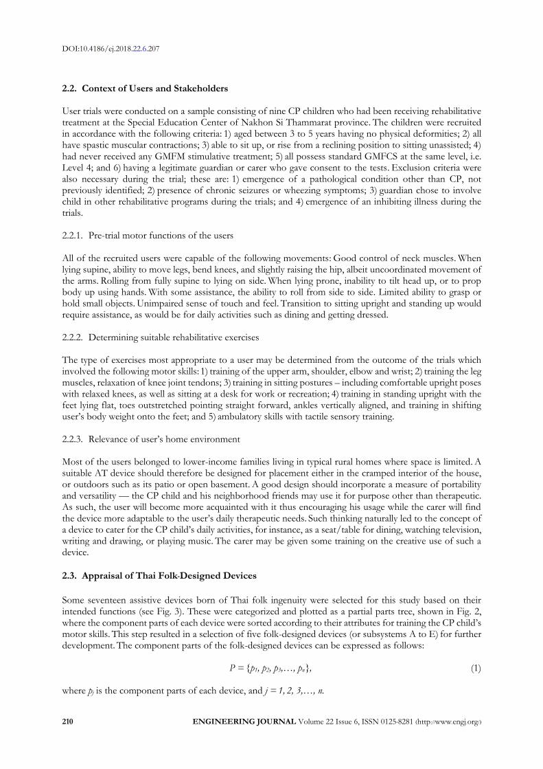
2.2. Context of Users and Stakeholders User trials were conducted on a sample consisting of nine CP children who had been receiving rehabilitative treatment at the Special Education Center of Nakhon Si Thammarat province. The children were recruited in accordance with the following criteria: 1) aged between 3 to 5 years having no physical deformities; 2) all have spastic muscular contractions; 3) able to sit up, or rise from a reclining position to sitting unassisted; 4) had never received any GMFM stimulative treatment; 5) all possess standard GMFCS at the same level, i.e. Level 4; and 6) having a legitimate guardian or carer who gave consent to the tests. Exclusion criteria were also necessary during the trial; these are: 1) emergence of a pathological condition other than CP, not previously identified; 2) presence of chronic seizures or wheezing symptoms; 3) guardian chose to involve child in other rehabilitative programs during the trials; and 4) emergence of an inhibiting illness during the trials. 2.2.1. Pre-trial motor functions of the users All of the recruited users were capable of the following movements: Good control of neck muscles. When lying supine, ability to move legs, bend knees, and slightly raising the hip, albeit uncoordinated movement of the arms. Rolling from fully supine to lying on side. When lying prone, inability to tilt head up, or to prop body up using hands. With some assistance, the ability to roll from side to side. Limited ability to grasp or hold small objects. Unimpaired sense of touch and feel. Transition to sitting upright and standing up would require assistance, as would be for daily activities such as dining and getting dressed. 2.2.2. Determining suitable rehabilitative exercises The type of exercises most appropriate to a user may be determined from the outcome of the trials which involved the following motor skills: 1) training of the upper arm, shoulder, elbow and wrist; 2) training the leg muscles, relaxation of knee joint tendons; 3) training in sitting postures – including comfortable upright poses with relaxed knees, as well as sitting at a desk for work or recreation; 4) training in standing upright with the feet lying flat, toes outstretched pointing straight forward, ankles vertically aligned, and training in shifting user’s body weight onto the feet; and 5) ambulatory skills with tactile sensory training. 2.2.3. Relevance of user’s home environment Most of the users belonged to lower-income families living in typical rural homes where space is limited. A suitable AT device should therefore be designed for placement either in the cramped interior of the house, or outdoors such as its patio or open basement. A good design should incorporate a measure of portability and versatility — the CP child and his neighborhood friends may use it for purpose other than therapeutic. As such, the user will become more acquainted with it thus encouraging his usage while the carer will find the device more adaptable to the user’s daily therapeutic needs. Such thinking naturally led to the concept of a device to cater for the CP child’s daily activities, for instance, as a seat/table for dining, watching television, writing and drawing, or playing music. The carer may be given some training on the creative use of such a device.
2.3. Appraisal of Thai Folk-Designed Devices
Some seventeen assistive devices born of Thai folk ingenuity were selected for this study based on their intended functions (see Fig. 3). These were categorized and plotted as a partial parts tree, shown in Fig. 2, where the component parts of each device were sorted according to their attributes for training the CP child’s motor skills. This step resulted in a selection of five folk-designed devices (or subsystems A to E) for further development. The component parts of the folk-designed devices can be expressed as follows: P = {p1, p2, p3,…, pn}, (1) where pj is the component parts of each device, and j = 1, 2, 3,…, n.

DOI:10.4186/ej.2018.22.6.207
ENGINEERING JOURNAL Volume 22 Issue 6, ISSN 0125-8281 (http://www.engj.org/) 211
A. Arm strengthening Category
B. Leg strengthening Category
C. Sitting skill Category
a. Arm muscles stretching Trainer (p1)
D. Standing skill Category
E. Walking skill Category
Desired Technical System
b. Excavator (control lever) (p2)c. Racing Chair (Control wheel) (p3)
d. Shovel Machine (the push bar) (p4)e. Spinner Chair (revolving cylinder control) (p5)
f. Double Pulley (p6)
a. Robot Exerciser (foot levers) (p7)
b. Flying Bicycle (the pedals) (p8)
c. Bicycle Pedaller (the pedals) (p9)
d. Push-pull Chair (the foot board) (p10)
e. Steering Chair (foot pedals) (p11)
a. Push-pull Chair (the seat) (p12)
b. Rocking Horse (the seat) (p13)
c. Robot Exerciser (the seat) (p14)
d. Excavator (the seat) (p15)
e. Back Tilt Chair (p16)
f. Flying Bicycle (the seat) (p17)
g. Sit-Stand Trainer (the seat) (p18)
a. Sit-Stand Trainer (standing board) (p19)
b. Vertical Board (p20)
a. Wheeled Walker (p21)
b. Walking Rails (p22) Fig. 2. Partial Parts Tree for analyzing folk-designed assistive devices.
Arm/leg muscles Trainer [28]
p1
Excavator [29]
p15
p2
Racing Chair [30]
p3
Shovel Machine[31]
p4 p5
p13 p18p20
p21
Spinner Chair Double Pulley
p6
Robot Exerciser [32] Flying Bicycle [33] Bicycle Pedaller Push-pull Chair[34]
Steering Chair [35]
p11p10
p12
p9
p8 p17
p7
p14
Rocking Horse [36]
Vertical BoardBack Tilt Chair [37]
Sit-StandTrainer [38]
Wheeled Walker Walking Rails
p16 p19
p22
Fig. 3. Drawings of Thai folk-designed devices.
2.4. Selecting Suitable Folk-Designed Pieces for Further Development A creativity technique developed by Shih-Wen Hsiao and Jyh-Rong Chou, the Sensuous Association Method (SAM) is employed to produce creative ideas by taking advantage of the design team’s sensuous association
DOI:10.4186/ej.2018.22.6.207
212 ENGINEERING JOURNAL Volume 22 Issue 6, ISSN 0125-8281 (http://www.engj.org/)
with everyday objects, plus the stimulation of the design environment. The method entails a measure of brainstorming among members of the team [10]. This step involves establishing the relationship between each component part and the conceptual needs envisioned for the new product, using the following mathematical procedures. 2.4.1. Sensuous association and conceptual need descriptors Based on a user-centred analysis, a set of 14 needs was selected as shown in Table 1 below. This can be arranged as follows: S = {s1, s2, s3,..., sq}, (2) Where si represents conceptual needs, and i = 1, 2, 3,…, q. 2.4.2. Building a Correlation Matrix between conceptual needs and component parts A practicable correlation between them should be identified as a tool to help apply the improvement ideas to the original device components. Based on Eq. (1) and Eq. (2), the correlation matrix, R, can be represented as:
R = ST·P = (s1, s2, s3,…, sq)T ·(p1, p2, p3,…, pn) = (rij)q x n, (3)
where i = 1, 2, 3,…, q; j =1, 2, 3,…, n. The entry rules of rij are defined thus: Rule 1: If si directly correlates with pj, then rij =1*. Rule 2: If si indirectly correlates with pj, then rij = 1. Rule 3: If si has no correlation with pj, then rij =0.
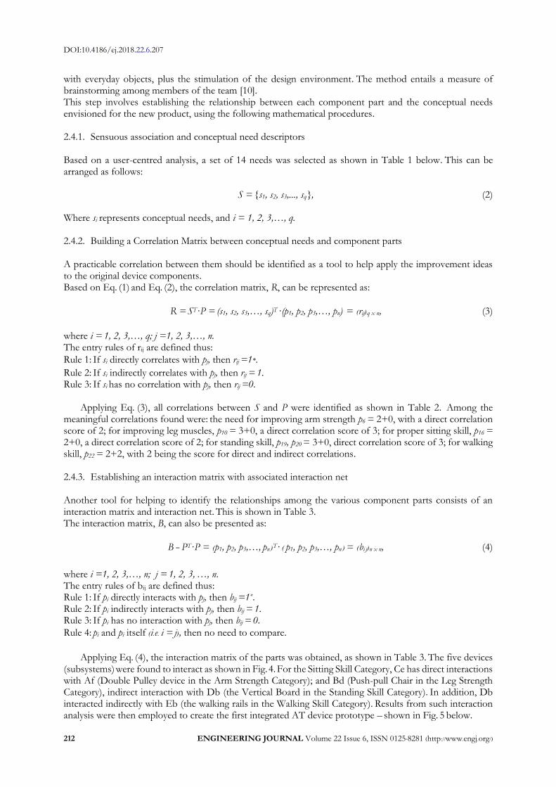
Applying Eq. (3), all correlations between S and P were identified as shown in Table 2. Among the meaningful correlations found were: the need for improving arm strength p6 = 2+0, with a direct correlation score of 2; for improving leg muscles, p10 = 3+0, a direct correlation score of 3; for proper sitting skill, p16 = 2+0, a direct correlation score of 2; for standing skill, p19, p20 = 3+0, direct correlation score of 3; for walking skill, p22 = 2+2, with 2 being the score for direct and indirect correlations. 2.4.3. Establishing an interaction matrix with associated interaction net Another tool for helping to identify the relationships among the various component parts consists of an interaction matrix and interaction net. This is shown in Table 3. The interaction matrix, B, can also be presented as:
B = PT·P = (p1, p2, p3,…, pn )T· ( p1, p2, p3,…, pn ) = (bi j)n x n, (4)
where i =1, 2, 3,…, n; j = 1, 2, 3, …, n. The entry rules of bij are defined thus: Rule 1: If pi directly interacts with pj, then bij =1*. Rule 2: If pi indirectly interacts with pj, then bij = 1. Rule 3: If pi has no interaction with pj, then bij = 0. Rule 4: pi and pi itself (i.e. i = j), then no need to compare.
Applying Eq. (4), the interaction matrix of the parts was obtained, as shown in Table 3. The five devices
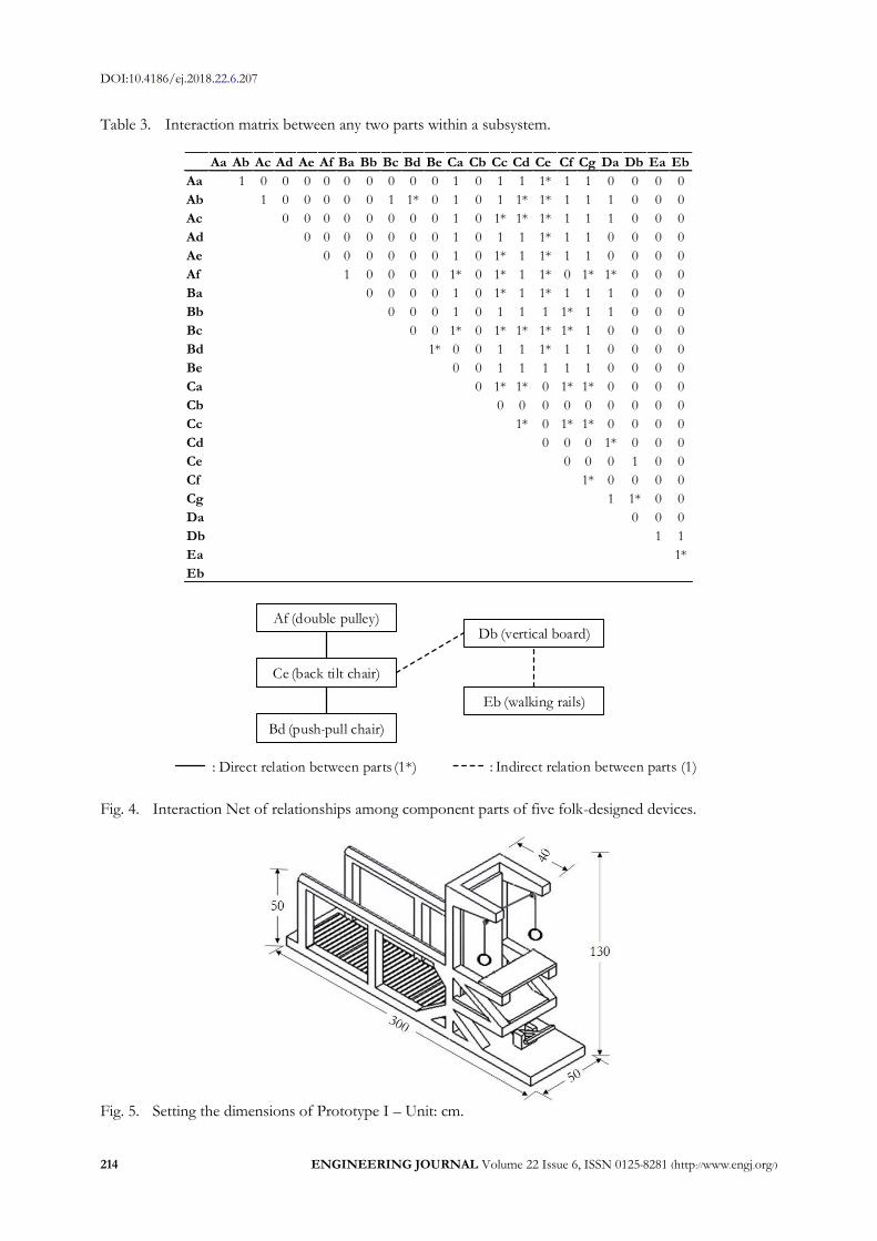
(subsystems) were found to interact as shown in Fig. 4. For the Sitting Skill Category, Ce has direct interactions with Af (Double Pulley device in the Arm Strength Category); and Bd (Push-pull Chair in the Leg Strength Category), indirect interaction with Db (the Vertical Board in the Standing Skill Category). In addition, Db interacted indirectly with Eb (the walking rails in the Walking Skill Category). Results from such interaction analysis were then employed to create the first integrated AT device prototype – shown in Fig. 5 below.

DOI:10.4186/ej.2018.22.6.207
ENGINEERING JOURNAL Volume 22 Issue 6, ISSN 0125-8281 (http://www.engj.org/) 213
Table 1. Conceptual descriptors of need for rehabilitation, as per 2.1.2.
Item Conceptual need descriptors Item Conceptual need descriptors
s1 Training for the joint muscles of shoulder, elbow, wrist and finger.
s8 Adopted for activities other than sitting training.
s2 Alternating up-down arm movements. s9 Standing exercise, with balance support device. s3 Lower leg rotation at the knee, forming
angles between 90 and 120 degrees. s10 Weight distribution on both feet.
s11 Toes stretched flat; ankle vertically aligned;
ankle ad leg forming right angle 90 degrees. s4 Training of leg muscles. s12 Mobility exercise with forward pacing. s5 Training of leg joints. s13 Forward pacing exercise. s6 Ability to sit in a relaxed manner with
back inclined at 120 degrees. s14 Pacing coordination exercises with tactile
sensory training. s7 Sitting posture training with torso, knee
angle, ankle angle at 90 degrees. Table 2. Relationship between conceptual needs and device parts.
2.5. Determining Prototype Features and Functions
As explained in 2.4.3, the SAM technique was employed to select five folk-designed assistive implements as the starting point for creating our integrated AT device. The chosen pieces are: 1) Pull-down Pulley; 2) Push-pull Chair; 3) Back Tilt Chair; 4) Vertical Board; and 5) Walking Rails. The first prototype (Prototype I) was built with dimensions determined from the authors’ measurement of the proportions of afflicted children whose physical growth is somewhat stunted (see Fig. 5).
p1 p2 p3 p4 p5 p6 p7 p8 p9 p10 p11 p12 p13 p14 p15 p16 p17 p18 p19 p20 p21 p22
s1 1* 1* 1* 0 0 1* 0 0 0 0 0 0 0 0 0 0 0 0 0 0 0 0
s2 0 0 0 0 0 1* 0 0 0 0 0 0 0 0 0 0 0 0 0 0 0 0
s3 0 0 0 0 0 0 1* 0 0 1* 1* 0 0 1 0 0 0 0 0 0 0 0
s4 0 0 0 0 0 0 0 0 0 1* 0 0 0 0 0 0 0 0 0 0 0 0
s5 0 0 0 0 0 0 0 1* 1* 1* 1* 0 0 0 0 0 0 0 0 0 0 0
s6 0 0 0 0 0 0 0 0 0 0 0 0 0 0 0 1* 0 0 0 0 0 0
s7 1 0 0 0 0 0 0 0 0 0 0 1* 0 1* 1* 0 0 1* 0 0 0 0
s8 0 0 0 0 0 0 0 0 0 0 0 0 0 0 0 1* 0 0 0 0 0 0
s9 0 0 0 0 0 0 0 0 0 0 0 0 0 0 0 0 0 1 1* 1* 1 1
s10 0 0 0 0 0 0 0 0 0 0 0 0 0 0 0 0 0 1 1* 1* 0 1
s11 0 0 0 0 0 0 0 0 0 0 0 0 0 0 0 0 0 1 1* 1* 0 0
s12 0 0 0 0 0 0 0 0 0 0 0 0 0 0 0 0 0 0 0 0 1* 1*
s13 0 0 0 0 0 0 0 0 0 0 0 0 0 1 0 0 0 0 0 0 0 1*
s14 0 0 0 0 0 0 0 0 0 0 0 0 0 0 0 0 0 0 0 0 0 0
Walking
skill
Arm
strength
Arm strength category Leg strength category Sitting skill category
Walking
skill
category
Conceptual
needs
Standing
skill
Sitting
skill
Leg
strength
Standing
skill
category
DOI:10.4186/ej.2018.22.6.207
214 ENGINEERING JOURNAL Volume 22 Issue 6, ISSN 0125-8281 (http://www.engj.org/)
Table 3. Interaction matrix between any two parts within a subsystem.
Af (double pulley)
Ce (back tilt chair)
Bd (push-pull chair)
Db (vertical board)
Eb (walking rails)
: Direct relation between parts (1*) : Indirect relation between parts (1)
Fig. 4. Interaction Net of relationships among component parts of five folk-designed devices.
Fig. 5. Setting the dimensions of Prototype I – Unit: cm.
Aa Ab Ac Ad Ae Af Ba Bb Bc Bd Be Ca Cb Cc Cd Ce Cf Cg Da Db Ea Eb
Aa 1 0 0 0 0 0 0 0 0 0 1 0 1 1 1* 1 1 0 0 0 0
Ab 1 0 0 0 0 0 1 1* 0 1 0 1 1* 1* 1 1 1 0 0 0
Ac 0 0 0 0 0 0 0 0 1 0 1* 1* 1* 1 1 1 0 0 0
Ad 0 0 0 0 0 0 0 1 0 1 1 1* 1 1 0 0 0 0
Ae 0 0 0 0 0 0 1 0 1* 1 1* 1 1 0 0 0 0
Af 1 0 0 0 0 1* 0 1* 1 1* 0 1* 1* 0 0 0
Ba 0 0 0 0 1 0 1* 1 1* 1 1 1 0 0 0
Bb 0 0 0 1 0 1 1 1 1* 1 1 0 0 0
Bc 0 0 1* 0 1* 1* 1* 1* 1 0 0 0 0
Bd 1* 0 0 1 1 1* 1 1 0 0 0 0
Be 0 0 1 1 1 1 1 0 0 0 0
Ca 0 1* 1* 0 1* 1* 0 0 0 0
Cb 0 0 0 0 0 0 0 0 0
Cc 1* 0 1* 1* 0 0 0 0
Cd 0 0 0 1* 0 0 0
Ce 0 0 0 1 0 0
Cf 1* 0 0 0 0
Cg 1 1* 0 0
Da 0 0 0
Db 1 1
Ea 1*
Eb

DOI:10.4186/ej.2018.22.6.207
ENGINEERING JOURNAL Volume 22 Issue 6, ISSN 0125-8281 (http://www.engj.org/) 215
2.6. Analyzing Design Defects in Prototype I Usability of Prototype I was assessed by applying the Usability Scale for Assistive Technology, or USAT technique [15], namely: activity & participation (Ua), device performance (Up), environmental factors (Ue), and user abilities & skills (Uc). Plus feedback from the original team of multidisciplinary specialists who assisted with the prototype design. Appraisals of the prototype attributes were made by a panel of three caregivers who had been properly trained in prototype uses. With the USAT technique, a reliability analysis was necessary whereby the Cronbach’s Alpha coefficient on the four subscales were measured, which yielded the following results: Ua = 0.752, Up = 0.738, Ue = 0.814, and Uc = 0.799 – all larger than 0.7. These results confirmed the consistency of our appraisal data [39, 40]. The caregivers were to appraise the devices in four attributes using data from field trials with the recruited users, or from video recordings thereof.
The prototype usability scores for the four user-product indicators, plotted in blue in Figs. 19 – 22 below, showed an acceptance level of 80% (Mean = 4). Usability ratings employed were: scores below 4, or a rating = 0, are unacceptable; scores greater than 4, or rating = 1, acceptable. Items failing this test were further analyzed in order to obtain further insights as to the flaws in the prototype.
Setting improvement targets. This step involved brainstorming for improvement ideas from the specialist team, which culminated in an array of nine targets – each may be tagged with sub-targets – which can be
represented as T = (t1, t2, t3,… , ti), where ti is our improvement target, and i = 1, 2, 3,…,n.
t1 = Height adjustability t3 = Sturdiness t5 = Reasonable pricing t7 = Appearance to attract users t9 = Ease of storage/ portability
t2 = Ease of use t4 = User Comfort t6 = Safety t8 = Adaptability for other activities
Table 4 displays the relationships between the usability ratings (U) and improvement targets for Prototype
I in terms of the USAT tests on the four indicators (Figs. 19 – 22). The results were obtained by modifying
Eq. (4) to arrive at the correlation matrix, R, as follows:
R = UT·T = (u1, u2, u3, …, uq)T · (t1, t2, t3, …, tn) = (rij)qxn, (5)
where i =1, 2, 3, …, q; j = 1, 2, 3,…, n. The entry rules of rij are defined thus: Rule 1: If ui correlates with tj, then rij = 1; the item is modifiable to meet improvement target tj. Rule 2: If ui does not correlate with tj, then rij = 0; i.e. the item cannot be modified to meet improvement target tj.
Table 5 shows outcome of the assessment of Prototype I in terms of the detected design flaws, or errors, and our improvement targets.
DOI:10.4186/ej.2018.22.6.207
216 ENGINEERING JOURNAL Volume 22 Issue 6, ISSN 0125-8281 (http://www.engj.org/)
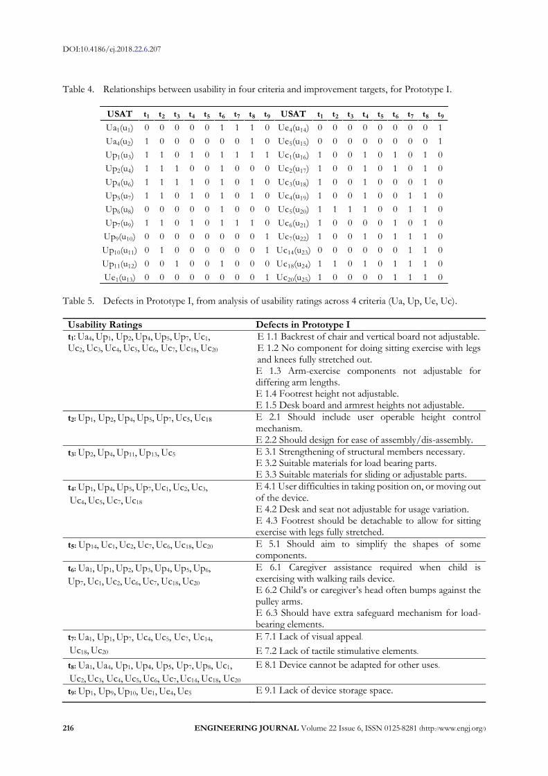
Table 4. Relationships between usability in four criteria and improvement targets, for Prototype I.
Table 5. Defects in Prototype I, from analysis of usability ratings across 4 criteria (Ua, Up, Ue, Uc).
Usability Ratings Defects in Prototype I
t1: Ua4, Up1, Up2, Up4, Up5, Up7, Uc1, Uc2, Uc3, Uc4, Uc5, Uc6, Uc7, Uc18, Uc20
E 1.1 Backrest of chair and vertical board not adjustable. E 1.2 No component for doing sitting exercise with legs and knees fully stretched out. E 1.3 Arm-exercise components not adjustable for differing arm lengths. E 1.4 Footrest height not adjustable. E 1.5 Desk board and armrest heights not adjustable.
t2: Up1, Up2, Up4, Up5, Up7, Uc5, Uc18 E 2.1 Should include user operable height control mechanism. E 2.2 Should design for ease of assembly/dis-assembly.
t3: Up2, Up4, Up11, Up13, Uc5 E 3.1 Strengthening of structural members necessary. E 3.2 Suitable materials for load bearing parts. E 3.3 Suitable materials for sliding or adjustable parts.
t4: Up1, Up4, Up5, Up7, Uc1, Uc2, Uc3, Uc4, Uc5, Uc7, Uc18
E 4.1 User difficulties in taking position on, or moving out of the device. E 4.2 Desk and seat not adjustable for usage variation. E 4.3 Footrest should be detachable to allow for sitting exercise with legs fully stretched.
t5: Up14, Uc1, Uc2, Uc7, Uc6, Uc18, Uc20 E 5.1 Should aim to simplify the shapes of some components.
t6: Ua1, Up1, Up2, Up3, Up4, Up5, Up6, Up7, Uc1, Uc2, Uc6, Uc7, Uc18, Uc20
E 6.1 Caregiver assistance required when child is exercising with walking rails device. E 6.2 Child’s or caregiver’s head often bumps against the pulley arms. E 6.3 Should have extra safeguard mechanism for load-bearing elements.
t7: Ua1, Up1, Up7, Uc4, Uc5, Uc7, Uc14,
Uc18, Uc20 E 7.1 Lack of visual appeal. E 7.2 Lack of tactile stimulative elements.
t8: Ua1, Ua4, Up1, Up4, Up5, Up7, Up8, Uc1,
Uc2, Uc3, Uc4, Uc5, Uc6, Uc7, Uc14, Uc18, Uc20 E 8.1 Device cannot be adapted for other uses.
t9: Up1, Up9, Up10, Ue1, Ue4, Ue5 E 9.1 Lack of device storage space.
USAT t1 t2 t3 t4 t5 t6 t7 t8 t9 USAT t1 t2 t3 t4 t5 t6 t7 t8 t9
Ua1(u1) 0 0 0 0 0 1 1 1 0 Ue4(u14) 0 0 0 0 0 0 0 0 1
Ua4(u2) 1 0 0 0 0 0 0 1 0 Ue5(u15) 0 0 0 0 0 0 0 0 1
Up1(u3) 1 1 0 1 0 1 1 1 1 Uc1(u16) 1 0 0 1 0 1 0 1 0
Up2(u4) 1 1 1 0 0 1 0 0 0 Uc2(u17) 1 0 0 1 0 1 0 1 0
Up4(u6) 1 1 1 1 0 1 0 1 0 Uc3(u18) 1 0 0 1 0 0 0 1 0
Up5(u7) 1 1 0 1 0 1 0 1 0 Uc4(u19) 1 0 0 1 0 0 1 1 0
Up6(u8) 0 0 0 0 0 1 0 0 0 Uc5(u20) 1 1 1 1 0 0 1 1 0
Up7(u9) 1 1 0 1 0 1 1 1 0 Uc6(u21) 1 0 0 0 0 1 0 1 0
Up9(u10) 0 0 0 0 0 0 0 0 1 Uc7(u22) 1 0 0 1 0 1 1 1 0
Up10(u11) 0 1 0 0 0 0 0 0 1 Uc14(u23) 0 0 0 0 0 0 1 1 0
Up11(u12) 0 0 1 0 0 1 0 0 0 Uc18(u24) 1 1 0 1 0 1 1 1 0
Ue1(u13) 0 0 0 0 0 0 0 0 1 Uc20(u25) 1 0 0 0 0 1 1 1 0

DOI:10.4186/ej.2018.22.6.207
ENGINEERING JOURNAL Volume 22 Issue 6, ISSN 0125-8281 (http://www.engj.org/) 217
Usability Ratings Defects in Prototype I
E 9.2 Difficulty in moving device around due to its sheer size and weight.
Each of the defects in Prototype I, as shown in Table 5, was considered and all of them re-grouped
according to their relevance to the subsystems of the prototype. For example, starting with E1.1, which was about the backrest and vertical board, the other defects were sorted for any relevance to this component, which were then assigned to the same ‘backrest’ category. Similarly, the next E (E1.2) was used as a starting point for the next series of defects. Following in this fashion, all of the E’s were examined and grouped into eight series as shown in Table 6 below. These formed the basis of the requirement (R) for the final solutions (S). Based on the skill and experience of the research team, a range of desirable S’s, or the goals of our exercise, was envisaged. These are shown in Table 6 below. 2.7. Using TRIZ and Specialist Input to Rectify Errors in Prototype I
TRIZ is an inventive technique for resolving conflicts between any two subsystems within a technical system. It provides broad ideas — known as ‘principles’— that serve as a starting point for creative problem solving. Turning such principles into meaningful solutions remains the work of the design engineer [41]. Users of the technique rely upon a set of prepared tables, lists and explanations which can be accessed via the TRIZ website: www.triz40.com.
The TRIZ process starts with determining the range of technical and physical contradictions within a problem area. These are identified by the theory’s 39 Features which give out two groups of numbers; one signifying improving features while the other its worsening features. Two numbers, one from each group, serve as coordinates for use with TRIZ’s “39 x 39 Contradictions” matrix, which in turn identifies a range of suggestions from its “40 Inventive Principles” list.
Due to the wide array of contradictions in the subsystems of Prototype I, the range of ‘principles’ obtained from TRIZ contained many repeats. The principles occurring with the highest frequencies were thus examined first, and suitable solutions systematically worked out along the suggestions given. (Note that the principles with lower frequencies of occurrence should not be dismissed entirely as they might prove to be more relevant in some cases.) Throughout the process, additional brainstorming and input by the specialist team proved to be very helpful.
Table 6 below features the listing of system contradictions, their improving and worsening features, the range of principles suggested by TRIZ and frequency of occurrence, and the principle chosen by the research team for guiding the resolution of contradictions. For the cases of R6 to R8, no technical contradictions nor physical contradictions were observed, and the listed defects were corrected through suggestions provided by the specialist team. Table 6. Application of TRIZ and specialist input to assess requirements and find solutions.
Defects in prototype I: Require Solve E1.1, E2.1, E2.2, E3.1, E3.2, E3.3, E6.3, E8.1: Adjust angle of incline for Back Tilt Chair and Vertical Tilt Board, to 95, 100, 120 degrees and 90, 120, 150, 180 degrees respectively. (R1)
Make backrest adjustable. (S1)
Approach to solving issue of backrest and vertical board Given that the backrest and the standing board were combined as a single component, it was redesigned to allow tilting of the piece to various angles of decline. This approach, however, led to some complexities in terms of component size, weight, and the locking mechanisms required. Technical Contradiction via TRIZ features; and proposed solutions (40 principles): Improving Features: 33. Ease of operation, 35. Adaptability or versatility Worsening Features: 1. Weight of moving object, 2. Weight of stationary object, 3. Length of moving object, 4. Length of stationary object, 5. Area of moving object, 6. Area of stationary object, 7. Volume of moving object, 8.Volume of stationary object, 36. Device complexity Inventive Principles (frequency): 15(8), 1(7), 16(5), 29(5), 35(5), 13(4), 6(3), 17(3), 2(2), 12(2), 18(2), 25(2), 39(2), 4(1), 7(1), 8(1) Applying Principle 15: Dynamisation, the chair backrest-cum-vertical

DOI:10.4186/ej.2018.22.6.207
218 ENGINEERING JOURNAL Volume 22 Issue 6, ISSN 0125-8281 (http://www.engj.org/)
Defects in prototype I: Require Solve board was redesigned to enable back-and-forth pivoting of the board. A metal rod holds the board between the two main posts, serving as the pivoting axis (see Figs. 11 and 15). Tilting board positions were re-designed as tensile forces in the form of a strap on each side, which holds the board to the main posts. Tilting is possible at 90, 95, 100, 120, 150, 180 degrees by adjusting the straps. A knob-operated screw locking device was provided (see Fig. 13). E1.5, E2.1, E2.2, E3.2, E3.3, E4.1, E4.2, E6.2, E8.1: Adjust desktop/armrest angle & height. (R2)
Install height adjustment mechanism. (S2)
Given that the desktop and armrest were to have the flexibility for height and incline adjustment as well as detachability, more complexities became necessary in terms of component size, weight, and the locking mechanisms required. Technical Contradiction via TRIZ features; and proposed solutions (40 principles):- Improving Features: 35. Adaptability or versatility Worsening Features: 1. Weight of moving object, 2. Weight of stationary object, 3. Length of moving object, 4. Length of stationary object, 5. Area of moving object, 6. Area of stationary object, 7. Volume of moving object, 8. Volume of stationary object Inventive Principles (frequency): 15(5), 29(5), 35(4), 1(3), 6(2), 16(2), 2(1), 7(1), 8(1), 19(1), 28(1), 30(1), 37(1) Applying Principle 1: Segmentation, the height and incline of the desk and its arm-rests were made adjustable by separating the parts. The desktop becomes detachable, while its seat is suspended from the armrests and its height and angle controlled through four sliding metal channels which allow desktop inclines of 0 – 30 degrees. Height of the armrests is also adjustable on the same metal-channel mechanism. A friction control knob is provided for locking the positions on the channels (See Figs. 9, 12 and 13). E1.2, E1.4, E2.1, E2.2, E3.3, E6.3, E7.2: Adjust angle of footboard to suit sitting training on the Back Tilt Chair, and sitting on floor with legs fully outstretched. (R3)
Make the footboard adjustable to desired height and also detachable. (S3)
Given the requirement to add the flexibility for adjustments in height, distance, and inclination of the footboard, more complexities became necessary in terms of component size, weight, and the locking mechanisms required. Technical Contradiction via TRIZ features; and proposed solutions (40 principles):- Improving Features: 35. Adaptability or versatility Worsening Features: 1. Weight of moving object, 2. Weight of stationary object, 3. Length of moving object, 4. Length of stationary object, 5. Area of moving object, 6. Area of stationary object, 7. Volume of moving object, 8. Volume of stationary object, 36. Device complexity Inventive Principles (frequency): 15(5), 39(5), 35(4), 1(3), 6(2), 16(2), 2(1), 7(1), 8(1), 19(1), 28(1), 30(1), 37(1). Applying principle 1: Segmentation, the footboard components are made detachable in order to enable adjustments in height, incline and entrance distance. The footboard can be reattached away from the backrest when the user is required to sit on the floor with his legs outstretched. For this function, it is secured by two metal channels and locked in place by a friction knob. (See Figs. 10 and 14). E6.1, E8.1: Allow the child to train walking skill unassisted by carer. (R4)
Walking rails & suspended pelvis support. (S4)
In order to prevent the child from falling over while in training, some form of a supporting device was necessary. The addition of such a device, however, may affect the weight, dimensions or flexibility of the design. Technical Contradiction via TRIZ features; and proposed solutions (40 principles):- Improving Features: 30. External harm affects the object. Worsening Features: 1. Weight of moving object, 2. Weight of stationary object, 3. Length of moving object, 7. Volume of moving object, 8. Volume of stationary objects, 13. Stability of object’s composition. Inventive Principles (frequency): 22(3), 27(3), 18(2), 19(2), 21(2), 24(2), 35(2), 1(1), 2(1), 15(1), 17(1), 30(1), 34(1), 37(1), 39(1). Applying principle 24: Intermediary, a pelvis support is provided. It is made of denim, shaped like a pair of shorts, and suspended from four adjustable straps from the topmost rails. It offers more support for the user’s balance in addition to his holding the rails. A softer
DOI:10.4186/ej.2018.22.6.207
ENGINEERING JOURNAL Volume 22 Issue 6, ISSN 0125-8281 (http://www.engj.org/) 219
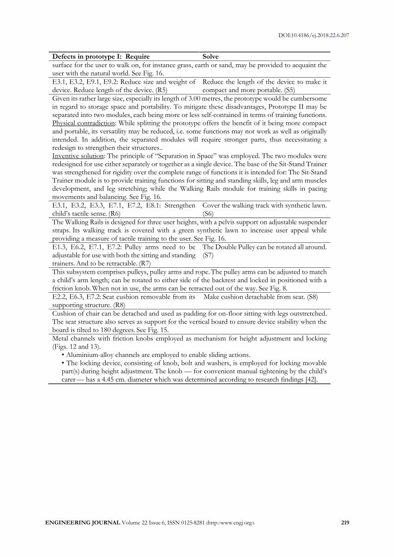
Defects in prototype I: Require Solve surface for the user to walk on, for instance grass, earth or sand, may be provided to acquaint the user with the natural world. See Fig. 16. E3.1, E3.2, E9.1, E9.2: Reduce size and weight of device. Reduce length of the device. (R5)
Reduce the length of the device to make it compact and more portable. (S5)
Given its rather large size, especially its length of 3.00 metres, the prototype would be cumbersome in regard to storage space and portability. To mitigate these disadvantages, Prototype II may be separated into two modules, each being more or less self-contained in terms of training functions. Physical contradiction: While splitting the prototype offers the benefit of it being more compact and portable, its versatility may be reduced, i.e. some functions may not work as well as originally intended. In addition, the separated modules will require stronger parts, thus necessitating a redesign to strengthen their structures.. Inventive solution: The principle of “Separation in Space” was employed. The two modules were redesigned for use either separately or together as a single device. The base of the Sit-Stand Trainer was strengthened for rigidity over the complete range of functions it is intended for: The Sit-Stand Trainer module is to provide training functions for sitting and standing skills, leg and arm muscles development, and leg stretching; while the Walking Rails module for training skills in pacing movements and balancing. See Fig. 16. E3.1, E3.2, E3.3, E7.1, E7.2, E8.1: Strengthen child’s tactile sense. (R6)
Cover the walking track with synthetic lawn. (S6)
The Walking Rails is designed for three user heights, with a pelvis support on adjustable suspender straps. Its walking track is covered with a green synthetic lawn to increase user appeal while providing a measure of tactile training to the user. See Fig. 16. E1.3, E6.2, E7.1, E7.2: Pulley arms need to be adjustable for use with both the sitting and standing trainers. And to be retractable. (R7)
The Double Pulley can be rotated all around. (S7)
This subsystem comprises pulleys, pulley arms and rope. The pulley arms can be adjusted to match a child’s arm length; can be rotated to either side of the backrest and locked in positioned with a friction knob. When not in use, the arms can be retracted out of the way. See Fig. 8. E2.2, E6.3, E7.2: Seat cushion removable from its supporting structure. (R8)
Make cushion detachable from seat. (S8)
Cushion of chair can be detached and used as padding for on-floor sitting with legs outstretched. The seat structure also serves as support for the vertical board to ensure device stability when the board is tilted to 180 degrees. See Fig. 15. Metal channels with friction knobs employed as mechanism for height adjustment and locking (Figs. 12 and 13).
• Aluminium-alloy channels are employed to enable sliding actions. • The locking device, consisting of knob, bolt and washers, is employed for locking movable part(s) during height adjustment. The knob — for convenient manual tightening by the child’s carer — has a 4.45 cm. diameter which was determined according to research findings [42].

DOI:10.4186/ej.2018.22.6.207
220 ENGINEERING JOURNAL Volume 22 Issue 6, ISSN 0125-8281 (http://www.engj.org/)
Figures 6 and 7 below show defects in Prototype I and outcome of their correction: Prototype II.
Fig. 6. Requirements for defect correction on Prototype I (R = Require).
Fig. 7. Prototype II, outcome of defect corrections (S = Solve) on previous design [43, 44].
DOI:10.4186/ej.2018.22.6.207
ENGINEERING JOURNAL Volume 22 Issue 6, ISSN 0125-8281 (http://www.engj.org/) 221
Fig. 8. pulley arms can be rotated 360o: (S7).
Fig. 9. desk board and armrest incline adjustable from 0 - 30°: (S2).
Fig. 10. Sitting with legs outstretched; feet pushing against footboard: (S3), (S8).
Fig. 11. Backrest adjustable to angles 95°, 100°, 120°: (S1).
Fig. 12. Metal channels for height adjustment.
Metal channels for height adjustment
Fig. 13. Friction knob for locking components.
Friction knob for manual tightening
WasherBolt intotimber frame
Bolt into timber frame
Fig. 14. Adjusting angle of footrest: (S3).
Fig. 15. Adjusting bodyweight bearing board for inclines at 95°, 100°, 120°, 150°, 180°: (S1).
Fig. 16. Sit-stand Trainer, Arm and Leg strength Trainer, Walking Trainer: (S1), (S4), (S5), (S6).
θ = 360°
θ = 30°9 cm18 cm
θ = 0°
θ = 15°
18 cm
t = 10 mm
θ = 0 - 30° θ = 0 - 45°
θ = 30°θ = 5° θ = 180° θ = 150°
θ = 30°
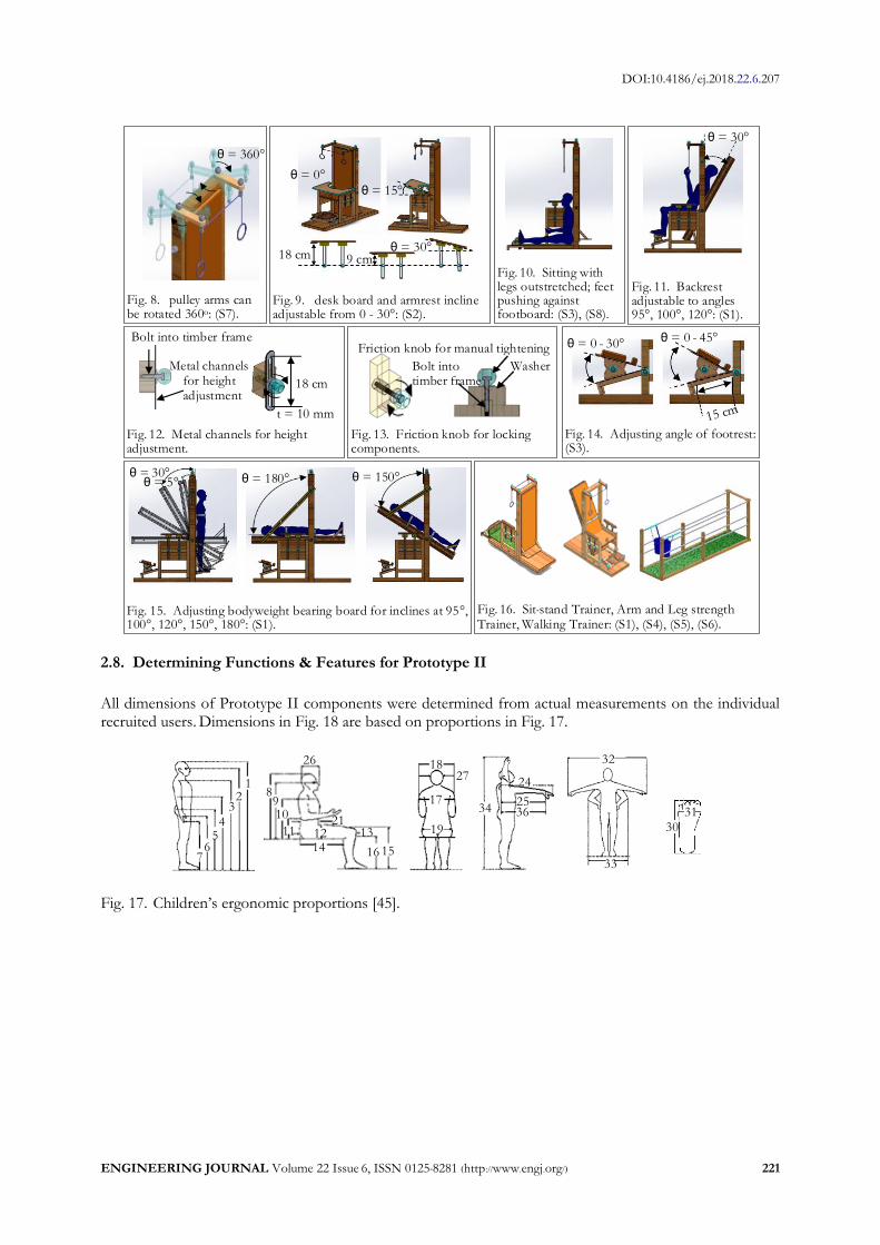
2.8. Determining Functions & Features for Prototype II
All dimensions of Prototype II components were determined from actual measurements on the individual recruited users. Dimensions in Fig. 18 are based on proportions in Fig. 17.
12
3
45
67
17
18
19
24
25
27
30
31
8910
11
1412 13
16 15
32
33
34 3621
26
Fig. 17. Children’s ergonomic proportions [45].

DOI:10.4186/ej.2018.22.6.207
222 ENGINEERING JOURNAL Volume 22 Issue 6, ISSN 0125-8281 (http://www.engj.org/)
H1: Seat height from floor = [(16) + 10] K: Footrest = [(30)+10] x [(17)] H2: Height of main supporting posts = [(1) + 20] L: Length of pulley support arms = 1/2 of (36) H3: Height of pelvic suspender rails = (3) O: Back cushion = [(17) + 10] x [(1) + 10] H4: Height of hand rails = (4) S: Base of chair = (33) x [(14) + (15)+10] H5: Height of pivoting rod = 1/3[(1) + 20] T: Base of footboard = (33) x [(14) + (15) + 10] H6: Height of incline control knob = 2/3[(1) + 20] U: Base of walking track = [(33)] x 200 H7: Desk height = [(11) + (16) + Desk thickness + 10] F: Size of desk = [(33) + 10] x (25)] G: Seat of chair = [(17) + 10] x [(14) - 5] Fig. 18. Dimensions of Prototype II (in centimeters), as per Fig. 17.
2.9. Usability Test Results on Prototype II
As represented by the red line in Figs. 19 – 22, usability tests were conducted to measure the key indicators
of Prototype II. Each of these received a score of over 4.0 signifying acceptance from the multidisciplinary team of testers. The test results, plotted in red on the graphs below, are summarized as follows: Ua having a mean score = 4.67, std dev = 0.29; Up, a mean score = 4.88, std dev = 0.14; Ue, mean score = 4.85, std dev = 0.21; and Uc, mean score = 4.72, std dev = 0.26.
Items of Ua
Usability scale
ability (5)
mild difficulty (4)
moderate difficulty (3)
reflecting extreme (2)
Inability (1)
Ua1: Mobility Ua2: Self-care Ua3: Home management Ua4: Work Ua5: Outdoor activities Ua6: Leisure activities Ua7: Communication Ua8: Learning
: Prototype I
: Prototype II
4.67 4.67
5.00 5.00
4.33
2.33
4.00
2.67
4.33
4.00
1 2 3 4 5 6 7 81 2 3 4 5 6 7 8
Fig. 19. Results of activity and participation (Ua).

DOI:10.4186/ej.2018.22.6.207
ENGINEERING JOURNAL Volume 22 Issue 6, ISSN 0125-8281 (http://www.engj.org/) 223
Up1: Effectiveness Up2: Efficiency Up3: Ease of use Up4: Suitability
Up5: Adjustability Up6: Reliability Up7: Endurance Up8: Appearance
Up9: Storage Up10: Portability Up11: Safety Up12: Privacy & security
Up13: Environmental impact Up14: Novelty Up15: Durability Up16: Maintenance
: Prototype I
: Prototype II
agree (4)
unsure (3)
Strongly disagree (1)
disagree (2)
Strongly agree (5)
Items of Up
Usability scale
5.00
4.334.67 4.67
5.00
4.33
2.33
2.00
4.00
2.33
2.673.33
2.00
4.00
1.67
2.33
3.674.00
1 2 3 4 5 6 7 8 9 10 11 12 13 14 15 162 3 4 5 6 7 8 9 11 151310 12 14 161
Fig. 20. Results of device performance (Up).
Fig. 21. Results of environmental factors (Ue).
Uc1: Strength Uc2: Joint integrity Uc3: Gross movements Uc4: Fine movements
Uc5: Hand functions Uc6: Postural control Uc7: Endurance Uc8: Understanding spoken language Uc9: Expressing spoken language Uc10: Understanding written language Uc11: Expressing written language Uc12: Vision Uc13: Hearing Uc14: Tactile sensation Uc15: Attention Uc16: Memory Uc17: Learning
Uc18: Motivation Uc19: Experience Uc20: Perceived independence
: Prototype I
: Prototype II
Very adequate (5)
adequate (4)
Fairly adequate (3)
inadequate (2)
Very inadequate (1)
Items of Uc
Usability scale
4.00
4.67
4.33
5.00
4.00
4.67
5.00
4.33
5.00
4.67
1.67
2.00
2.67
2.33
4.00
4.00
2.33
4.00
3.00
4.00
1.67
1 2 3 4 5 6 7 8 9 10 11 12 13 14 15 16 17 18 19 201 2 3 4 5 6 7 8 9 11 151310 12 14 16 1917 18 20
Fig. 22. Results of user abilities and skills (Uc).
Usability scale
Very favorable (5)
favorable (4)
Neutral (3)
unfavorable (2)
Very unfavorable (1)
Ue1: Physical space Ue2: Environmental safety Ue3: Surface flooring, terrain Ue4: Transportation Accessibility
Ue5: Transportation safety Ue6: Noise levels Ue7: Electronic accessibility Ue8: Climatic conditions
Ue9: Light Ue10: Acceptance Ue11: Training
Items of Ue
4.67 5.004.67
4.33
5.00
3.33
4.33
1.67
2.67
4.00
4.67
1 2 3 4 5 6 7 8 9 10 11
: Prototype I
: Prototype II
1 2 3 4 5 6 7 8 9 10 11
DOI:10.4186/ej.2018.22.6.207
224 ENGINEERING JOURNAL Volume 22 Issue 6, ISSN 0125-8281 (http://www.engj.org/)
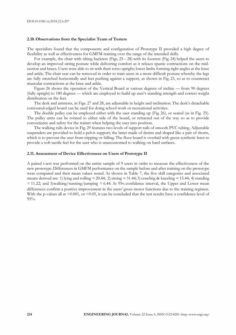
2.10. Observations from the Specialist Team of Testers The specialists found that the components and configuration of Prototype II provided a high degree of flexibility as well as effectiveness for GMFM training over the range of the intended skills.
For example, the chair with tilting backrest (Figs. 25 – 28) with its footrest (Fig. 24) helped the users to develop an improved sitting posture while delivering comfort as it relaxes spastic contractions on the mid-section and knees. Users were able to sit with their torso upright; lower limbs forming right angles at the knee and ankle. The chair seat can be removed in order to train users in a more difficult posture whereby the legs are fully stretched horizontally and feet pushing against a support, as shown in Fig. 23, so as to counteract muscular contractions at the knee and ankle.
Figure 26 shows the operation of the Vertical Board at various degrees of incline — from 90 degrees (fully upright) to 180 degrees — which are employed to build up user’s standing strength and correct weight distribution on the feet.
The desk and armrests, in Figs. 27 and 28, are adjustable in height and inclination. The desk’s detachable contoured-edged board can be used for doing school work or recreational activities.
The double pulley can be employed either with the user standing up (Fig. 26), or seated (as in Fig. 25). The pulley arms can be rotated to either side of the board, or retracted out of the way so as to provide convenience and safety for the trainer when helping the user into position.
The walking rails device in Fig. 29 features two levels of support rails of smooth PVC tubing. Adjustable suspenders are provided to hold a pelvis support; the latter made of denim and shaped like a pair of shorts, which is to prevent the user from tripping or falling. The floor board is overlaid with green synthetic lawn to provide a soft tactile feel for the user who is unaccustomed to walking on hard surfaces.
2.11. Assessment of Device Effectiveness on Users of Prototype II A paired t-test was performed on the entire sample of 9 users in order to measure the effectiveness of the new prototype. Differences in GMFM performance on the sample before and after training on the prototype were compared and their mean values noted. As shown in Table 7, the five skill categories and associated means derived are: 1) lying and rolling = 20.44; 2) sitting = 31.44; 3) crawling & kneeling = 15.44; 4) standing
= 11.22; and 5)walking/running/jumping = 6.44. At 95% confidence interval, the Upper and Lower mean
differences confirm a positive improvement in the users’ gross motor functions due to the training regimen. With the p-values all at <0.001, or <0.05, it can be concluded that the test results have a confidence level of 95%.

DOI:10.4186/ej.2018.22.6.207
ENGINEERING JOURNAL Volume 22 Issue 6, ISSN 0125-8281 (http://www.engj.org/) 225
Fig. 23. Leg stretch training.
Fig. 24. Footrest.
Fig. 26. Standing training at various angles of incline & arm training with pulleys.
Fig. 25. Sitting training with rope pulling for arm
strength.
Fig. 27. Daily activities on the desk withtop surface inclined.
Fig. 28. Sitting posture supported by armrests.
Fig. 29. Standing and walking skill training.
Table 7. Paired t-test results on gross motor functions before and after using AT device.
N Mean Std. Deviation
Std. Error Mean
95% Confidence Interval of the Difference p-value
Lower Upper
Lying and rolling
Pre-Post 9 20.44 5.13 1.71 16.5 24.38 <0.001
Sitting
Pre-Post 9 31.44 7.25 2.42 25.87 37.02 <0.001
Crawling & kneeling
Pre-Post 9 15.44 3.47 1.16 12.78 18.11 <0.001
Standing
Pre-Post 9 11.22 2.86 0.95 9.02 11.76 <0.001
Walking, running & jumping
Pre-Post 9 6.44 1.13 0.38 5.58 7.31 <0.001

DOI:10.4186/ej.2018.22.6.207
226 ENGINEERING JOURNAL Volume 22 Issue 6, ISSN 0125-8281 (http://www.engj.org/)
3. Discussion The design process devised for this study is comprised of 9 steps. Steps 1 and 2 determine a suitable study approach and appraise the context of AT device usage [5, 6, 8, 46]. Step 3 involves using a partial parts tree, which enumerates the attributes of the devices, to analyze the relationships between each component part and the five subsystems of rehabilitative training for the CP child, namely: the strengthening of arm and leg functions, skills in sitting, standing and walking. Steps 4 and 5 seek to identify correlations between the conceptual needs for device users and desirable attributes in the finished AT design [10]. The SAM procedure is employed in order to select a range of suitable folk-designed devices for incorporating into the prototype [10]. Five folk-designed devices are selected, namely: double pulley, push-pull chair, vertical tilt board, back tilt chair, and walking rails. The process is carried forward to achieve Prototype I. Thereafter, in Step 6, a usability test is performed wherein the Cronbach’s alpha coefficients of the four subscales are measured in order to verify the internal consistency of our test data. Step 7 involves applying the USAT protocol to highlight defects (or errors) in Prototype I. Step 8 is where the TRIZ method is applied to arrive at an array of potential solutions to the problems found on Prototype I. The design process then loops back to Step 5 whereby the defects so far identified are corrected, leading to a new and improved Prototype II. The new design is then brought for re-assessment according to Step 6. Upon passing the new round of USAT testing, the prototype is brought for field testing in Step 9 where a sample of users are recruited for testing whereby their GMFM-88 before and after using the AT device are measured. The before/after effectiveness is then verified by a paired t-test.
4. Conclusion Apart from its user-centered approach, the design process presented herein took advantage of the SAM and TRIZ protocols. SAM was beneficial in encouraging creative input from our specialist team of academics and care-giving therapists, while TRIZ enabled the design team to quickly arrive at optimal solutions to any practical issues on the prototypes. The final design was assessed for its effectiveness and user satisfaction through the USAT procedure. Field tests were carried out on a sample – consisting of nine CP children – to measure their GMFM-88 functions before and after use of the final prototype. Outcomes of the field tests showed significant progress in the afflicted children in regard to the strengthening of their motor skills in sitting, standing, and walking. In conclusion, the design process is a viable method for upgrading the efficiency and effectiveness of folk-designed devices by integrating them into a single AT system. Further design refinement is possible by re-invoking the TRIZ procedure for the purpose. The process can be conveniently adopted for creating similar AT devices with the promise of high effectiveness at a low production cost.
Acknowledgements The authors wish to express their appreciation to the following agencies for their support and assistance in the project: Institute of Research and Development, Nakhon Si Thammarat Rajabhat University, Office of Higher Education Commission, the multidisciplinary team of the Special Education Center of Nakhon Si Thammarat, Foundation for Children with Disabilities, and the Maharaj Hospital of Nakhon Si Thammarat. The project has passed committee review on Ethical Conduct for Research Involving Humans, of the Borommarachachonani Nursing College, Nakhon Si Thammarat province.
References [1] E. G. Fowler, T. H. Kolobe, D. L. Damiano, D. E. Thorpe, D. W. Morgan, and J. E. Brunstrom,
“Promotion of physical fitness and prevention of secondary conditions for children with cerebral palsy: Section on pediatrics research summit proceedings,” Physical Therapy, vol. 87, no. 11, pp. 1495-1510, 2007.
[2] D. McDonagh, A. Bruseberg, and C. Haslam, “Visual product evaluation: exploring users’ emotional relationships with products,” Appl Ergonomics, vol. 33, no.33, pp. 231-240, 2002.
[3] E. A. Koldoff and B. J. Holtzclaw, “Physical activity among adolescents with cerebral palsy: An integrative review,” Journal of Pediatric Nursing, vol. 30, no. 5, pp. 105-117, 2015.

DOI:10.4186/ej.2018.22.6.207
ENGINEERING JOURNAL Volume 22 Issue 6, ISSN 0125-8281 (http://www.engj.org/) 227
[4] P. C. Hallal, C. G. Victora, M. R. Azevedo, and J. C. Wells, “Adolescent physical activity and health: A systematic review,” Sports Medicine, vol. 36, no. 12, pp. 1019-1030, 2006.
[5] M. Y. Ma, F. G. Wu, and C. H. Chen, “A new design approach of user-centered design on a personal assistive bathing device for hemiplegic,” Disability and Rehabilitation, vol. 29, no. 14, pp. 1077-1089, 2006.
[6] F. G. Wu, M. Y. Ma, and C. H. Chen, “A new user-centered design approach: A hair-washing assistive device design for users with shoulder mobility restriction,” Applied Ergonomics, vol. 40, no. 5, 2009.
[7] C. Magnier, G. Thomann, F. Villeneuv, and P. Zwolinski, “Methods for designing assistive devices extracted from 16 case studies in the literature,” Int J Interact Des Manuf, vol. 6, no. 2, pp. 93-100, 2012.
[8] C. C. Lin and D. B. Luh, “A vision-oriented approach for innovative product design,” Advanced Engineering Informatics, vol. 23, no. 2, pp. 191-200, 2009.
[9] M. Westendorp, S. Houwen, E. Hartman, and C. Visscher, “Are gross motor skills and sports participation related in children with intellectual disabilities?,” Developmental Disabilities, vol. 32, no. 3, pp. 1147–1153, 2011.
[10] S. W. Hsiao and J. R. Chou, “A creativity-based design process for innovative product design,” International Journal of Industrial Ergonomics, vol. 34, no. 5, pp. 421-443, 2004.
[11] T. Benjaboonyazit, “Systematic approach to problem solving of low quality arc welding during pipeline maintenance using ARIZ (Algorithm of Inventive Problem Solving),” Engineering Journal, vol. 18, no. 4, pp. 113-133, 2014.
[12] T. Benjaboonyazit, “Systematic Approach to arowana gender identification problem using Algorithm of Inventive Problem Solving (ARIZ),” Engineering Journal, vol. 18, no. 2, pp. 13-28, 2014.
[13] P. A. Verhaegen, J. D’hondt, J. Vertommen, S. Dewulf, and J. R. Duflou, “Relating properties and functions from patents to TRIZ trends,” CIRP J of Manuf Science & Technology, vol. 1, no. 3, 2008.
[14] M. C. Young and H. Stephen, “Approaches for evaluating the usability of assistive devices,” Technology Product Prototypes Assistive Technology, vol. 23, no. 1, pp. 36-41, 2011.
[15] S. Arthanat, “Development of an instrument to measure usability of assistive technology devices,” Ph.D. thesis, Department of Rehabilitation Science, the State University of New York at Buffalo, 2007.
[16] D. J. Russell, P. L. Rosenbaum, L. M. Avery, and M. Lane, Gross Motor Function Measure (GMFM-66 and GMFM-88), Users’ Manual, 2nd ed. London UK: Mac Keith Press, 2013.
[17] B. Toms, B. Harrison, and E. Bower, “A pilot study to compare the use of prototypes of multi-positional paediatric walking sticks and tripods with conventional sticks and tripods by children with cerebral palsy,” Child Care Health Dev, vol. 33, no. 1, pp. 96-106, 2007.
[18] M. Alotaibi, T. Long, E. Kennedy, and S. Bavishi, “The efficacy of GMFM-88 and GMFM-66 to detect changes in gross motor function in children with cerebral palsy (CP): A literature review,” Disabil Rehabil, vol. 36, no.8, pp. 617-627, 2013.
[19] M. Salavati, E. A. A. Rameckers, A. Waninge, W. P. Krijnen, B. Steenbergen, and C. P. van der Schans, “Gross motor function in children with spastic Cerebral Palsy and Cerebral Visual Impairment: A comparison between outcomes of the original and the Cerebral Visual Impairment adapted Gross Motor function measure-88 (GMFM-88-CVI),” Research in Developmental Disabilities, vol. 60, pp. 269-276, 2017.
[20] M. R. Golberg and J. L. Pearlman, “Best practices for team-based assistive technology design courses,” Annals of Biomedical Engineering, vol. 41, no. 9, pp. 1880-1888, 2013.
[21] S. Ostensjo, E. B. Carlberg, and N. K. Vollestad, “The use and impact of assistive devices and other environmental modifications on everyday activities and care in young children with cerebral palsy,” Disability and Rehabilitation, vol. 27, no. 14, pp. 849-861, 2005.
[22] J. M. Voorman, A. J. Dallmeijer, C. Schuengel, D. L. Knol, G. J. Lankhorst, and J. G. Becher, “Activities and participation of 9- to 13-year-old children with cerebral palsy,” Clinical Rehabilitation, vol. 20, no. 11, pp. 937-948, 2006.
[23] P. Rosenbaum, N. Paneth, A. Leviton, M. Goldstein, and M. Bax, “A report: Definition and classific-ation of cerebral palsy April 2006,” Developmental Medicine and Child Neurology, vol. 49, no. 109, pp. 8-14, 2007.
[24] L .A. Boyd and C. J. Winstein, “Cerebellar stroke impairs temporal but not spatial accuracy during implicit motor learning,” Neurorehabilitation and Neural Repair, vol. 18 no. 3, pp 134-143, 2004.
[25] L. A. Boyd, E. D. Vidoni, C. F. Siengsukon, and B. D. Wessel, “Manipulating time-to-plan alters patterns of brain activation during the Fitts’ task,” Experimental Brain Research, vol. 194, pp. 527-539, 2009.

DOI:10.4186/ej.2018.22.6.207
228 ENGINEERING JOURNAL Volume 22 Issue 6, ISSN 0125-8281 (http://www.engj.org/)
[26] J. G. Zwickera, C. Missiunab, S. R. Harrisc, and L. A. Boyd, “Brain activation associated with motor skill practice in children with developmental coordination disorder: An fMRI study,” Int J Dev Neurosci, vol. 29, no. 2, pp. 145-152, 2011.
[27] E. D. Vidoni, N. E. Acerra, E. Dao, S. K. Meehan, and L. A. Boyd, “Role of the primary somatosensory cortex in motor learning: an rTMS study,” Neurobiology of Learning and Memory, vol. 93, no. 3, pp. 532–539, 2010.
[28] P. Weerapong and N. Rodfan, “Arm and leg muscle trainer for children with celebral palsy,” Thailand Petty Patent Pending, 1703002437, Oct. 24, 2017.
[29] P. Weerapong and S. Bunluepuet, “Excavator for children with celebral palsy,” Thailand Petty Patent Pending, 1703002428, Oct. 24, 2017.
[30] P. Weerapong and S. Yothanan, “Racing chair for children with celebral palsy,” Thailand Petty Patent Pending, 1703002434, Oct. 24, 2017.
[31] P. Weerapong and S. Chaiphet, “Shovel machine for children with celebral palsy,” Thailand Petty Patent Pending, 1703002429, Oct. 24, 2017.
[32] P. Weerapong and I. Phonranoe, “Robot exerciser for children with celebral palsy,” Thailand Petty Patent Pending, 1703002432, Oct. 24, 2017.
[33] P. Weerapong and S. Saesiao, “Flying bicycle for children with celebral palsy,” Thailand Petty Patent Pending, 1703002438, Oct. 24, 2017.
[34] P. Weerapong, “Push pull chair for children with celebral palsy,” Thailand Petty Patent Pending, 1703002436, Oct. 24, 2017.
[35] P. Weerapong, “Steering chair for children with celebral palsy,” Thailand Petty Patent Pending, 1703002435, Oct. 24, 2017.
[36] P. Weerapong, “Rocking hosre for children with celebral palsy,” Thailand Petty Patent Pending, 1703002433, Oct. 24, 2017.
[37] P. Weerapong, “Back tilt chair for children with celebral palsy,” Thailand Petty Patent Pending, 1703002431, Oct. 24, 2017.
[38] P. Weerapong, “Sit stand trainer for children with celebral palsy,” Thailand Petty Patent Pending, 1703002430, Oct. 24, 2017.
[39] L. G. Portney and M. P. Watkins, Foundations of clinical research: Application to practice, 2nd ed. New Jersey: Prentia-Hall, 2000.
[40] J. C. Nunnally and I. R. Bernstein, Psychometric Theory, 3rd ed. New York: Mcgraw-Hill, 1994. [41] S. D. Savransky, Engineering of Creativity: Introduction to TRIZ Methodology of Inventive Problem Solving. Boca
Raton, Florida, 2000.
[42] H. Dreyfuss. (1960). The Measure of Man: Human Factors in Design [Online]. Available:
http://design.data.free.fr/RUCHE/documents/Ergonomie%20Henry%20DREYFUS.pdf [43] P. Weerapong and U. Numnaphol, “Physiologically integrated devices for children with celebral palsy,”
Thailand Petty Patent Application, 13231, Oct. 24, 2017. [44] P. Weerapong and U. Numnaphol, “Physiologically integrated devices for children with celebral palsy,”
Thailand Patent Pending, 1601002574, May 4, 2016. [45] F. Sadeghi, A. Mazloumi, and Z. Kazemi, “An anthropometric data bank for the Iranian working
population with ethnic diversity,” Appl Ergon, vol. 48, pp. 95-103, 2015. [46] Y. C. Manresa and R. Mas, “Designing an accessible low-cost interactive multi-touch surface,” Univers
Access Inf Soc, vol. 15, no. 3, pp. 419-429, 2016.