upgrading feasibility study on upper seti (damauli storage hydroelectric project in...
TRANSCRIPT

Nepal Electricity Authority Nepal
UPGRADING FEASIBILITY STUDY ON
UPPER SETI (DAMAULI) STORAGE HYDROELECTRIC PROJECT
IN NEPAL
FINAL REPORT < SUMMARY >
June 2007
JAPAN INTERNATIONAL COOPERATION AGENCY
ELECTRIC POWER DEVELOPMENT CO., LTD.
NIPPON KOEI CO., LTD.
No.
E D
J R 07-076

Location Map
Upper Seti (Damauli) Storage
Hydroelectric Project
Kathmandu
Pokhara

River Corridor Study Region
Bhimad Dajar
Wantang Khale
Outlet
Powerhouse
Dam SitePhedi Khola
TutuwaReservoir

View of Dam Site from Upstream Side
View of Intake

Tailrace Outlet
View of Upstream Reservoir (Bhimad Bajar)

Stakeholder Meeting in Damauli (2 June, 2006)
Stakeholder Meeting in Damauli (2 June, 2006)

Upgrading Feasibility Study on Upper Seti Storage Hydroelectric Project in Nepal
CONTENTS
CONCLUSION AND RECOMMENDATION ..................................................................................1 Conclusion......................................................................................................................................1 Recommendations ..........................................................................................................................7
1 INTRODUCTION......................................................................................................................8 2 GENERAL INFORMATION OF NEPAL..................................................................................9
2.1 General Information ............................................................................................................9 2.2 Macroeconomics .................................................................................................................9 2.3 Tenth Plan..........................................................................................................................10
3 EXISTING STUDY ON SELECTION OF STORAGE HYDROELECTRIC PROJECT.......12 3.1 Power Facilities for Peak Demand ....................................................................................12 3.2 Study on the Selection of Storage Hydroelectric Project ..................................................12 3.3 Feasibility Study by NEA..................................................................................................13 3.4 Investigations by NEA ......................................................................................................14
4 POWER SECTOR SURVEY ...................................................................................................15 4.1 Organization ......................................................................................................................15 4.2 Existing Facilities for Generation and Transmission Lines...............................................15 4.3 Actual Records of Power Supply and Demand .................................................................15 4.4 Electricity Tariff ................................................................................................................17 4.5 Financial Performance of NEA .........................................................................................17 4.6 Actual Situation of Power Sector Reform.........................................................................18
5 POWER DEVELOPMENT PLAN ..........................................................................................19 5.1 Load Demand Forecast......................................................................................................19 5.2 Development Plan .............................................................................................................20 5.3 Justification of Project observed from Power Development Scheme ...............................22
6 HYDROLOGY AND SEDIMENTOLOGY.............................................................................27 6.1 Outline...............................................................................................................................27 6.2 River Discharge.................................................................................................................27 6.3 Flood..................................................................................................................................29 6.4 Sedimentology...................................................................................................................30
7 GEOLOGY...............................................................................................................................33 7.1 Outline of the Geology of the Project Area .......................................................................33 7.2 Site Geology......................................................................................................................33
8 SEISMICITY............................................................................................................................45 8.1 Evaluation Based on Aseismic Design Code in Nepal ......................................................45 8.2 Evaluation Based on India Standard..................................................................................45 8.3 Evaluation of Maximum Acceleration...............................................................................47 8.4 Evaluation of Maximum Acceleration based on the Seismic Hazard Map of Nepal ........48
Summary Report - i -
Upgrading Feasibility Study on Upper Seti Storage Hydroelectric Project in Nepal
8.5 Design Horizontal Seismic Coefficient for Upper Seti Project .........................................49 9 ENVIRONMENTAL IMPACT ASSESSMENT ......................................................................50
9.1 Review of the Existing EIA Report ...................................................................................50 9.2 Supplemental EIA by the JICA Study Team......................................................................51 9.3 Natural Environment Impact Assessment .........................................................................51
9.3.1 Mitigation Measures for Physical Environment ........................................................51 9.3.2 Framework of Watershed Management Plan .............................................................53 9.3.3 Mitigation Measures for Biological Environment .....................................................53
9.4 Socio-Economic and Cultural Environmental Impact Assessment ...................................54 9.4.1 Key Socio-Economic and Cultural Effects ................................................................54 9.4.2 The Framework of Resettlement Plan .......................................................................55 9.4.3 Preparation of Social Action Plan..............................................................................56
9.5 Stakeholder Meetings ........................................................................................................59 9.6 IEE for Transmission Line – Damauli to Bharatpur..........................................................59
9.6.1 Objectives ..................................................................................................................59 9.6.2 Project Line Route and Affected Areas......................................................................60 9.6.3 Alignment Alternatives ..............................................................................................60 9.6.4 Physical Environment ................................................................................................60 9.6.5 Biological Environment.............................................................................................61 9.6.6 Socio-economic and Cultural Environment...............................................................61 9.6.7 Environmental Impacts and Mitigation .....................................................................61 9.6.8 Findings and Conclusion ...........................................................................................62
9.7 Environmental Management Framework for the Project ..................................................62 9.7.1 Stakeholders under the Environmental Management Plan ........................................62 9.7.2 Project’s Environmental Management Office............................................................62 9.7.3 Stakeholders under the Environmental Management Plan ........................................63
10 OPTIMIZATION OF THE DEVELOPMENT PLAN .............................................................64 10.1 Layout Alternatives ...........................................................................................................64 10.2 FSL Alternatives................................................................................................................66 10.3 Optimization Study............................................................................................................66
11 PROJECT DESIGN..................................................................................................................69 11.1 General ..............................................................................................................................69 11.2 Dam and Auxiliary Structures ...........................................................................................75 11.3 Waterway and Powerhouse................................................................................................81 11.4 Electromechanical Equipment...........................................................................................89 11.5 Transmission Line .............................................................................................................90 11.6 Annual Energy.................................................................................................................100
12 CONSTRUCTION PLAN AND COST FOR CONSTRUCTION.........................................101
Summary Report - ii -

Upgrading Feasibility Study on Upper Seti Storage Hydroelectric Project in Nepal
12.1 Implementation Plan and Schedule .................................................................................101 12.1.1 Basic Conditions......................................................................................................101 12.1.2 Implementation Plan and Schedule..........................................................................102
12.2 Construction Cost ............................................................................................................105 12.2.1 Basic Criteria for Cost Estimate ..............................................................................105 12.2.2 Constitution of Project Cost.....................................................................................105 12.2.3 Project Construction Cost ........................................................................................106 12.2.4 Disbursement Schedule ...........................................................................................106
13 ECONOMIC AND FINANCIAL EVALUATION .................................................................108 13.1 Economic Evaluation ......................................................................................................108
13.1.1 Methodology............................................................................................................108 13.1.2 Economic Cost of the Project ..................................................................................108 13.1.3 Economic Benefit of the Project ..............................................................................108 13.1.4 Economic Evaluation...............................................................................................108
13.2 Financial Evaluation........................................................................................................108 13.2.1 Methodology............................................................................................................108 13.2.2 Financial Cost and Benefit of the Project ................................................................109 13.2.3 Financial Evaluation ................................................................................................109
Summary Report - iii -

Upgrading Feasibility Study on Upper Seti Storage Hydroelectric Project in Nepal
LIST OF TABLES
Table 4.4-1 Tariff Rate ........................................................................................................... 17 Table 5.1-1 Demand Load Forecast and Peak Load by NEA ................................................ 19 Table 5.3-1 Demand and Supply Balance up to FY 2013/14................................................. 22 Table 6.2-1 Generated Average Monthly River Discharge at Dam Site ................................ 28 Table 6.3-1 Probable Flood.................................................................................................... 29 Table 8.2-1 Basic Seismic Coefficient in Indian Seismic Hazard Region ............................. 47 Table 8.3-1 Summary of Maximum Acceleration Estimation
at the Upper Seti Dam Site ................................................................................. 47 Table 8.3-2 Seismic Coefficient Based Upon Maximum Acceleration ................................. 48 Table 8.5-1 Result of Seismic Coefficient Estimation obtained in Various Ways ................. 49 Table 9.4-1 VDCs/Municipality and Wards Affected by the Project Components................ 54 Table 9.4.2-1 Major Resettlement Effects on APs and Possible Mitigating Measures............. 55 Table 9.4.2-2 Proposed Compensation and Benefits of APs..................................................... 56 Table 9.4.3-1 Socio-economic Effects on Communities and
Possible Mitigating Measures............................................................................. 57 Table 9.4.3-2 Proposed Social Programs .................................................................................. 58 Table 10.3-1 Main Features of Selected Development Plan in Chapter 10 ............................. 68 Table 12.2.3-1 Construction Cost ............................................................................................... 106 Table 12.2.4-1 Disbursement Schedule of Project Construction Cost ........................................ 107 Table 13.1.4-1 Results of Economic Evaluation......................................................................... 108
Summary Report - iv -

Upgrading Feasibility Study on Upper Seti Storage Hydroelectric Project in Nepal
LIST OF FIGURES
Fig. 4.3-1 Energy Demand and Peak Load.......................................................................... 16 Fig. 4.3-2 Maximum Daily Load Curve on 12 Jan. 2006.................................................... 16 Fig. 5.1-1 Comparison of Energy Demand Forecast between NEA and JICA.................... 20 Fig. 5.2-1 Capacity of Generation and Peak Load .............................................................. 21 Fig. 5.2-2 Yearly Load Duration Curve(2004/05 and 2005/06) .......................................... 22 Fig. 5.2-3 Daily Load and Duration Curve on 2013/14 ...................................................... 22 Fig. 5.3-1 Daily Load Curve Expected................................................................................ 25 Fig. 6.2-1 Trend of Generated Average Annual River Discharge at Dam Site .................... 27 Fig. 6.3-1 Synthesis of Unit Hydrographs........................................................................... 30 Fig. 6.4-1 Riverbed Profile of Reservoir with Sediment Flushing Gates............................ 31 Fig. 7.2-1 Geologic Plan of Damsite ................................................................................... 39 Fig. 7.2-2 Geologic Section of Damsite (A-A) ................................................................... 41 Fig. 7.2-3 Geologic Profile of Waterway & Powerhouse (Option III-b)............................. 43 Fig. 8.1-1 Seismic Hazard Map in Nepal ............................................................................ 45 Fig. 8.2-1 Seismic Hazard Map in India ............................................................................. 46 Fig. 8.4-1 Seismic Hazard Map in Nepal ............................................................................ 49 Fig. 9.6.3-1 Alignment Alternatives....................................................................................... 60 Fig. 10.1-1 Option I General Plan ......................................................................................... 64 Fig. 10.1-2 Option I Waterway section.................................................................................. 64 Fig. 10.1-3 Option II General Plan........................................................................................ 65 Fig. 10.1-4 Option II Waterway Section................................................................................ 65 Fig. 10.1-5 Option IIIa General Plan..................................................................................... 65 Fig. 10.1-6 Option IIIa Waterway Section ............................................................................ 65 Fig. 10.1-7 Option IIIb General Plan .................................................................................... 66 Fig. 10.1-8 Option IIIb Waterway Section ............................................................................ 66 Fig. 10.1-9 Option IV General Plan ...................................................................................... 66 Fig. 10.1-10 Option IV Waterway Section .............................................................................. 66 Fig. 11.1-1 General Plan ....................................................................................................... 71 Fig. 11.1-2 General Profile of Waterway & Powerhouse...................................................... 73 Fig. 11.2-1 Dam General Plan in Detail ................................................................................ 77 Fig. 11.2-2 Dam Section Profile............................................................................................ 79 Fig. 11.3-1 Waterway Plan, Profile and Section ................................................................... 83 Fig. 11.3-2 Arrangement of Powerhouse and Related Tunnels............................................. 85 Fig. 11.3-3 Details of Underground Powerhouse.................................................................. 87 Fig. 11.5-1 (1) Final route-1 ....................................................................................................... 93 Fig. 11.5-1 (2) Final route-2 ....................................................................................................... 95 Fig. 11.5-1 (3) Final route-3 ....................................................................................................... 97
Summary Report - v -
Upgrading Feasibility Study on Upper Seti Storage Hydroelectric Project in Nepal
Fig. 12.1.1-1 Land Utilization Plan.......................................................................................... 101 Fig. 12.1.1-2 Location of Concrete Production Plant............................................................... 102 Fig. 12.1.2-1 Construction Schedule ........................................................................................ 103
Summary Report - vi -

Upgrading Feasibility Study on Upper Seti Hydroelectric Project in Nepal
SummaryAB - 1
ABBREVIATIONS
Organizations
ADB Asian Development Bank
BFRS Begnas Fisheries Research Station
CBO Community-Based Organization
CBS Central Bureau of Statistics
CDO Chief District Officer
DANIDA Danish International Development Agency
DDC District Development Committee
DFO District Forestry Office
DHM Department of Hydrology and Meteorology
DOED Department of Electricity Development
FINIDA Finish International Development Agency
INGO International Non-Governmental Organization
IUCN International Union for Conservation of Nature and Natural Resources
JBIC Japan Bank for International Cooperation
JICA Japan International Cooperation Agency
KfW Kreditanstalt fur Wiederaufbau
KMTNC King Mahendra Trust for Nature Conservation
LDC Load Dispatch Center
LDO Local Development Officer
MOEST Ministry of Environment, Science and Technology
MOF Ministry of Finance
MOFSC Ministry of Forest and Soil Conservation
MOWR Ministry of Water Resources
NEA Nepal Electricity Authority
NGO Non-Governmental Organization
NRCT Nepal River Conservation Trust
VDC Village Development Committee
UNDP United Nations Development Programme
USBR United States Bureau of Reclamation
WB World Bank
General and technical terms
AFC Automatic Frequency Control
AGC Automatic Generation Control

Upgrading Feasibility Study on Upper Seti Hydroelectric Project in Nepal
SummaryAB - 2
AIDS Acquired Immunodeficiency Syndrome
ASTM American Society for Testing and Materials
B/C Benefit-Cost Ratio
BOD Biological Oxygen Demand
CITES Convention on International Trade in Endangered Species of Wild Fauna and Flora
COD Chemical Oxygen Demand
CPI Consumer Price Index
D/D Detailed Design
DEM Digital Elevation Model
EIA Environmental Impact Assessment
EIRR Economic Internal Ratio of Return
EL. Elevation
EMP Environmental Management Plan
FC Foreign Currency
FIRR Financial Internal Ratio of Return
FSL Full Supply Level
F/S Feasibility Study
FY Fiscal Year
GDP Gross Domestic Product
GIS Geographic Information System
GIS Gas Insulated Switchgear
HEP Hydroelectric Project
HIV Human Immunodeficiency Virus
IEE Initial Environmental Evaluation
IPP Independent Power Producer
IRR Internal Ratio of Return
INPS Integrated Nepal Power System
JIS Japanese Industrial Standards
LAN Local Area Network
LC Local Currency
LOLP Loss of Load Probability
MOL Minimum Operation Level
NPV Net Present Value
O & M Operation and Maintenance
ODA Official Development Assistance
PMF Probable Maximum Flood

Upgrading Feasibility Study on Upper Seti Hydroelectric Project in Nepal
SummaryAB - 3
PMP Probable Maximum Precipitation
PPA Power Purchase Agreement
PROR Peaking Run-off-River
PRSP Poverty Reduction Strategy Paper
RAP Resettlement Action Plan
ROE Return on Equity
ROI Return on Investment
ROR Run-off-River
SAP Social Action Plan
SCADA Supervisory Control and Data Acquisition
VAT Value Added Tax
WPI Wholesale Price Index
Units
A Ampere
ha Hect Are
Hz Hertz (Cycles per second)
JRT Japan tone of refrigiration
Lu Lugeon Value
MCM Million Cubic Meter
MVar Megavar
m mol/L Mili-mol per liter
m3/s Cubic meter per second
ppm Parts per million
V Volt
kV Kilovolt = 103 V
VA Volt Ampere
kVA Kilovolt Ampere = 103 VA
MVA Megavolt Ampere = 106 VA
W Watt
kW Kilowatt = 103 W
MW Megawatt = 106 W
Wh Watt Hour
kWh Kilowatt Hour = 103 Wh
MWh Megawatt Hour = 106 Wh
GWh Gigawatt Hour = 109 Wh
NRs Nepalese Rupees

Upgrading Feasibility Study on Upper Seti Hydroelectric Project in Nepal
SummaryAB - 4
US$ US Dollar
USc US Cent

MAIN FEATURES OF UPPER SETI STORAGE HYDROELECTRIC PROJECT
River Name of River Seti River
Catchment Area 1502 km2
Annual Inflow 3,380 x 106 m3
Reservoir Full Supply Level 415.0 m
Minimum Operation Level 387.2 m
Available Depth 27.8 m
Sedimentation Level 386.2 m
Gross Storage Capacity 295.1 x 10⁶ m3
Effective Storage Capacity 167 x 106 m3
Dam Type Concrete Gravity Dam
Height x Crest length 140.0 m x 170.0 m
Volume of Dam 890 x 103 m3
Spillway Design Flood 7,377m3/s
Type of Gate Radial
Size & Number of Gate 12.5 m x 12.5 m, 6
Intake Type Surface Intake
Number One (1)
Headrace Tunnel Number
Inner Diameter x Length 7.8 m x 927 m
Penstock Number One (1) to Two (2)
Inner Diameter 7.8 m to 3.1 m
Total Length 195 m
Powerhouse Type Underground
Size Wide 22 m x High 42 m x Long 90 m
Development Plan Intake Water level 410.0 m
Tail Water Level 289.2 m
Effective Head 112.5 m
Maximum Discharge 127.4 m3/s
Install Capacity 127 MW
Turbine Type Vertical Shaft, Francis Turbine
Turbine Output x Number 65,100 kW x 2
Generator Type Three-phases, Synchronous Generator
Rated Output x Number 74,700 kVA x 2
Switchyard Type GIS (Gas Insulated Switchgear)
Voltage 220 kV
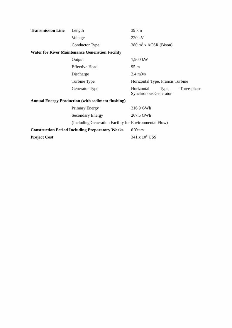
Transmission Line Length 39 km
Voltage 220 kV
Conductor Type 380 m3 x ACSR (Bison)
Water for River Maintenance Generation Facility
Output 1,900 kW
Effective Head 95 m
Discharge 2.4 m3/s
Turbine Type Horizontal Type, Francis Turbine
Generator Type Horizontal Type, Three-phase Synchronous Generator
Annual Energy Production (with sediment flushing)
Primary Energy 216.9 GWh
Secondary Energy 267.5 GWh
(Including Generation Facility for Environmental Flow)
Construction Period Including Preparatory Works 6 Years
Project Cost 341 x 106 US$

Upgrading Feasibility Study on Upper Seti Storage Hydroelectric Project in Nepal
CONCLUSION AND RECOMMENDATION
This upgrading feasibility study was implemented with respect to the Upper Seti (Damauli) Storage Hydroelectric Project from February 2005, and the Project was judged feasible from technological, economical, financial and environmental perspectives for the following reasons as a result of the study. The details of the conclusion are discussed below.
Conclusion
(1) Necessity of Hydropower Development for Peak Load
The exploitable hydropower potential is estimated to be 42,000 MW, and water resources are the only energy resource in Nepal, due to the lack of any nationwide fossil energy reserves in the country. The Government of Nepal is implementing rural electrification and hydroelectric development, by using abundant water resources, in the Tenth Plan (FY 2002/03-to FY 2007/08) as one of the activities for poverty reduction which is the most important national issue to be solved.
The total installed capacity in Nepal is 614 MW as of July 2006, of which 93% consists of hydropower. Hydropower shares 99% of annual generated energy.
National power demand in the country has grown steadily, and the growth rates of annual generating energy and the maximum load in the past decade have been 8.3% and 8.2% on average, respectively.
The daily peak load in the country is recorded in the morning and from 5:00 to 10:00 in the evening, and daily load curves show typical examples where domestic demand dominates.
The annual maximum load is recorded in December or January during a dry season during which river discharge decreases. 85% of hydropower facilities in installed capacity is consisted of Run-of-river (ROR) type hydropower plants which cannot seasonally regulate discharge for power generation against peak demand, and new power plants are necessary to cope with such peak demand.
Oil-fired/gas-fired thermal power plants are generally considered as power sources suitable to meet peak demand. Thermal power plants, however, are not considered as new power facilities, for the following reasons:
a. The expensive generation cost b. The risk associated with fuel procurement and the foreign currency required for same c. Priority for the utilization of rich national water resources
With the above in mind, reservoir type hydropower plants are under consideration as new power facilities to meet peak demand.
Summary Report - 1 -

Upgrading Feasibility Study on Upper Seti Storage Hydroelectric Project in Nepal
(2) Power Demand Forecast
In 2006, the NEA forecasts that both the required generating energy and the maximum demand will grow at an annual rate of 8.1% right up to 2020.
In the latest the power development plan, demand will exceed supply capacity up to 2013, and shortage should be dealt with via power imports from India or load shedding, because some of projects to be implemented by Independent Power Producers (IPPs) have been delayed. Even after 2013, there is the potential for power shortages, if projects by NEA and IPPs are not advanced steadily.
The Upper Seti Hydroelectric Power Plant is planned as that for peak demand and is capable of supplying power for 6 hours during peak times throughout the year (also supplying power during off-peak times in the rainy season).
In addition, the plant can play roles in stabilizing system power voltage and system frequency during evening peak periods during which the power load increases rapidly. The new transmission line of the project will represent one of the very important steps for forming a strong 220 kV loop to enhance the power system reliability.
(3) Study Process
NEA carried out a study termed the Identification and Feasibility Study of Storage Project to identify storage type hydroelectric projects and to select priority project(s), in order to cope with increasing peak demand. In the study, an initial total of 102 new projects were identified through desk study. The Project was selected as the priority choice following coarse screening using the existing data and information and fine screening based on the site survey results.
NEA performed a feasibility study on the Project from July 2000 up to July 2001. In the study based on the site surveys (topography, hydrology, geology and environment), a development plan featuring 122 MW in installed capacity was concluded.
The upgrading feasibility study including site surveys (hydrology, geology and environment) was carried out and completed in July 2004. Based on the results of the above environmental survey NEA prepared an environmental impact assessment (EIA) in January 2003, and held a public consultation in Damauli located near the site in January 2004 in accordance with Nepalese regulations. The EIA was submitted to the Department of Electricity Development of the Ministry of Water Resources which is the supervisory organization of NEA.
(4) Natural Conditions
The Project site is located in the upper part of the Seti River, a tributary of the Trishuli River flowing in the central part of Nepal. The Seti River originates at the Annapurna (7,555 m height above sea level) of the Himalaya Mountains and flows about from north to south. The length
Summary Report - 2 -

Upgrading Feasibility Study on Upper Seti Storage Hydroelectric Project in Nepal
of the Seti River from the origin to the Dam site is about 120 km, and a catchment area at the Dam site is 1,502 km2.
The average annual precipitation in the project basin is 2,973 mm of which about 80% falls between June and September due to the influence of the southwest monsoon. Annual sediment at the project site is estimated at 6,240 m3/km2. According to sedimentation analysis, the reservoir will not function due to sedimentation around 40 years after completion of the construction works, if sediment is not discharged from the reservoir. Hence sediment flushing facilities are to be installed in the dam.
(5) Environmental and Social Considerations
Although the environmental impact assessment (EIA) for the Project had been carried out by NEA, an environmental survey was performed in the Study to supplement to the existing survey results. The scopes of the supplementary survey were prepared based on the review results of the existing EIA, discussions with NEA, and the requirements of the JICA Guidelines for Environmental and Social Considerations.
Topographic maps of the following two regions were prepared by using satellite images, to effectively implement the environmental survey:
a. The Seti river watershed region at a scale of 1:25,000 b. Reservoir area at a scale of 1/5,000
Data obtained by satellite image analysis and collected during the survey were compiled in the geographic information system (GIS) data base.
Stakeholder meetings were held by the NEA with the assistance of the Study Team both in Damauli located near the site and in Kathmandu three times, during the preparation of scoping, submission of the interim report and submission of the draft final report, in accordance with the JICA Guidelines for Environmental and Social Considerations. The Study Team explained the scoping of the supplemental survey, field survey results, and the Study results, etc. according to the progress of the Study. Opinions and comments raised in the meetings were incorporated into the Study.
EIA was prepared based on the results of the supplementary survey, and required mitigation measures, monitoring programs, framework of resettlement plan, and social action program were prepared. The costs for these were estimated.
Regarding the resettlement plan, although NEA proposed to prepare it in their EIA during the detailed design stage, a framework of the plan had to be prepared during the feasibility study stage under the JICA Guidelines for Environmental and Social Considerations and those issued by other international organizations.
Summary Report - 3 -

Upgrading Feasibility Study on Upper Seti Storage Hydroelectric Project in Nepal
The Study Team reviewed the mitigation measures and the resettlement plan applied to Kali Gandaki A and Middle Marsyangdi hydropower projects in Nepal which are similar to the Project, in terms of mitigation measures and a framework of the resettlement plan, in order to apply measures suitable for Nepalese situations to the Project.
NEA’s EIA does not include the transmission line from the power station to Bharatpur, where it will be connected to the NEA’s power system. In the Study the initial environmental evaluation (IEE) was performed and basic mitigation measures were proposed.
A framework of the environmental management plan for the Project was prepared to surely implement the environmental mitigation measures and monitoring program proposed in the Study. It is proposed that the environmental management unit should be established in the NEA’s Project management office. The unit will play the leading role in the environmental management.
(6) Optimization of Development Plan
In the study of optimization of power generation development, cost efficiency was compared to the maximum discharge for power generation at several full supply levels (FSL) for five alternative layouts, based on the peak hours required in terms of demand and supply being six hours obtained during an examination of power demand records. Compensation and mitigation costs are considered for each FSL.
As a result, FSL is to be EL. 425 m with the layout featuring a waterway passing in the mountains by using Seti River’s meandering downstream of the dam selected. In addition, the minimum operation level (MOL) was lowered with .a intake portal structure to effectively use reservoir water and to reduce the effects on the environment. Consequently, FSL of EL. 415 m is selected as the optimum development plan, following comparison of both FSLs.
(7) Overview of the Development Project
The Project is of a dam-waterway power type power generation scheme. The dam will be a concrete gravity dam 140 m in height and approximately 890,000 m3 in volume, which will regulate an annual average inflow of 3,380 × 106 m3 by the reservoir with an effective storage capacity of 167 × 106 m3.
With regard to the water for power generation, a maximum discharge of 127.4 m3/s will be taken from the intake located around 400 m upstream of the dam and will be conveyed to the power station via a headrace tunnel 927 m long and a penstock of approximately 195 m in extension. Electricity with an annual energy production of 484 GWh will be generated at the maximum output (two units) of 127 MW and evacuated via a 220 kV transmission line to the new Bharatpur switchyard to be connected with 220 kV trunk lines that are under planning.
Summary Report - 4 -
Upgrading Feasibility Study on Upper Seti Storage Hydroelectric Project in Nepal
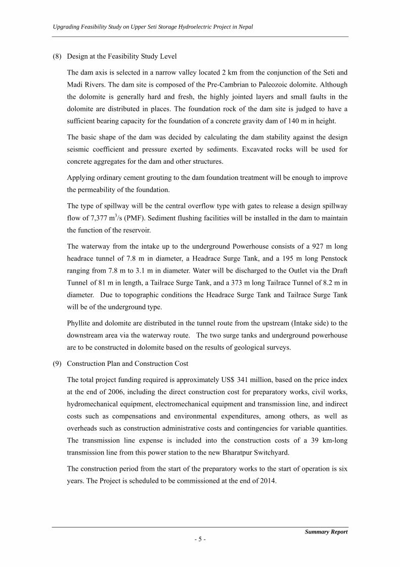
(8) Design at the Feasibility Study Level
The dam axis is selected in a narrow valley located 2 km from the conjunction of the Seti and Madi Rivers. The dam site is composed of the Pre-Cambrian to Paleozoic dolomite. Although the dolomite is generally hard and fresh, the highly jointed layers and small faults in the dolomite are distributed in places. The foundation rock of the dam site is judged to have a sufficient bearing capacity for the foundation of a concrete gravity dam of 140 m in height.
The basic shape of the dam was decided by calculating the dam stability against the design seismic coefficient and pressure exerted by sediments. Excavated rocks will be used for concrete aggregates for the dam and other structures.
Applying ordinary cement grouting to the dam foundation treatment will be enough to improve the permeability of the foundation.
The type of spillway will be the central overflow type with gates to release a design spillway flow of 7,377 m3/s (PMF). Sediment flushing facilities will be installed in the dam to maintain the function of the reservoir.
The waterway from the intake up to the underground Powerhouse consists of a 927 m long headrace tunnel of 7.8 m in diameter, a Headrace Surge Tank, and a 195 m long Penstock ranging from 7.8 m to 3.1 m in diameter. Water will be discharged to the Outlet via the Draft Tunnel of 81 m in length, a Tailrace Surge Tank, and a 373 m long Tailrace Tunnel of 8.2 m in diameter. Due to topographic conditions the Headrace Surge Tank and Tailrace Surge Tank will be of the underground type.
Phyllite and dolomite are distributed in the tunnel route from the upstream (Intake side) to the downstream area via the waterway route. The two surge tanks and underground powerhouse are to be constructed in dolomite based on the results of geological surveys.
(9) Construction Plan and Construction Cost
The total project funding required is approximately US$ 341 million, based on the price index at the end of 2006, including the direct construction cost for preparatory works, civil works, hydromechanical equipment, electromechanical equipment and transmission line, and indirect costs such as compensations and environmental expenditures, among others, as well as overheads such as construction administrative costs and contingencies for variable quantities. The transmission line expense is included into the construction costs of a 39 km-long transmission line from this power station to the new Bharatpur Switchyard.
The construction period from the start of the preparatory works to the start of operation is six years. The Project is scheduled to be commissioned at the end of 2014.
Summary Report - 5 -

Upgrading Feasibility Study on Upper Seti Storage Hydroelectric Project in Nepal
(10) Economic and Financial Evaluation
For the purpose of this study, the following two kinds of benefits were adopted: one is the saved cost of alternative thermal power project (gas turbine), and the other is the long run marginal cost during wet season for the secondary energy. From this evaluation, the Economic Internal Rates of Return (EIRR) were estimated at 12.3% which exceeded the opportunity cost of capital of 10%. Thus it was evaluated to be economically feasible.
Financial benefit of the Project is the revenue to be earned by the electricity sale. On the condition that the average sale price will increase by 5% per annum due to NEA’s semi-automatic adjustment, Financial Internal Rates of Return (FIRR) is estimated at 10.3%, and it was found out that the Project is found out to be financially feasible, when compared with the expected interest rate of 8% for use of on-lent loan from the Government.
According to the sensitivity analysis, FIRR is estimated as 8% in the case that the tariff will raise by 5% three times up to 2014.
Summary Report - 6 -

Upgrading Feasibility Study on Upper Seti Storage Hydroelectric Project in Nepal
Recommendations
In light of the electric power conditions of Nepal, where power demand exceeds supply capacity, the Upper Seti Storage Hydroelectric Project that provides response to peak hours should be promoted as a candidate for the next hydropower project.
This hydroelectric project is feasible from technical, economic/financial and environmental perspectives and can be developed as a power generation project which will also contribute to stability of the national power system. The operation can begin around at the end of 2014, given the time required for tasks to take place subsequent to this Feasibility Study, including geological investigations, hydraulic model tests, detailed design, funding arrangement and construction work, among others. The following will have to be completed before implementing this project:
(1) In the detailed design, the results of additional investigations as shown in Chapter 14 “Future Investigations” of the final report should be sufficiently incorporated and at the same time documents for bidding and contracting of construction works with a higher accuracy of construction cost estimates.
(2) Arrangement of finance, bidding for construction works, and the selection of contractors will have to be performed before the construction of this project. In addition, the construction of the new road and improvement work of the existing road leading within the vicinity of the dam site will have to be completed before the construction launch of this project.
(3) Appropriate compensation should be provided to people whose houses will be affected by the immersion due to r the reservoir and by construction of the project facility, in accordance with the resettlement plan. Activities stipulated in the social action plan for the Project should be implemented.
Summary Report - 7 -

Upgrading Feasibility Study on Upper Seti Storage Hydroelectric Project in Nepal
1 INTRODUCTION
The Upgrading Feasibility Study (hereinafter referred to as the Study) aims at formulating an optimum plan and assessing the technical, economic and financial, and environmental viabilities of the Upper Seti Storage Hydroelectric Project (hereinafter referred to as the Project) located in the central of Nepal, in assisting the Nepal Electricity Authority (hereinafter referred to as NEA), the counterpart agency of the Study, in conducting Environmental Impact Assessment (hereinafter referred to as EIA). The Study also aims to carry out the technology transfer to Nepalese counterpart personnel over the course of the Study and recommending the further process of the project implementation.
The Government of Nepal is implementing rural electrification and hydroelectric development, by using abundant water resource, in the Tenth Plan (FY 2002/03-FY 2007/08) as one of the activities for poverty reduction, which is the most important national issue to be solved.
The total installed capacity in Nepal was 611 MW as of July 2006, of which 90% is generated by hydropower, with run-of-river (ROR) type hydropower plants dominating capacity. Because ROR type plants cannot seasonally regulate discharge for power generation, a storage type hydropower plant must be constructed, which is capable of annually regulating discharge for generation against peak demand, to cope with increasing power demand.
NEA performed studies on storage type hydropower development and identified the Upper Seti Storage Project in the studies (see “3 Existing Study on Selection of Storage Hydroelectric Project”). The Government of Nepal requested that the Government of Japan implement an upgrading feasibility study (Upgrading F/S) under the technical assistance of Japan.
JICA, the organization executing technical assistance of the Government of Japan, conducted a project formation study in July 2004 and a preliminary study in October 2004, respectively. S/W was concluded between NEA and JICA on November 24, 2004. Based on the S/W, the Study was commenced by the JICA Study Team in February 2005. The Study was suspended due to concerns on security issues at the site from April 2005 to January 2006 and restarted in February 2006.
The Study Team carried out data collection, review of the existing studies concerned, hydrological and sedimentologic studies, studies on geology and construction materials, environmental impact assessment, power sector survey, GIS mapping, optimization of development plan, project designs at the feasibility study level, preparation of construction plans, estimation of the project construction cost, economic and financial evaluation. During the Study assisted NEA in holding stakeholder meetings based on the JICA Guidelines for Environmental and Social Considerations.
The Study was completed in June 2007 after the Final Report including Environmental and Social Considerations Report was submitted to JICA.
Summary Report - 8 -

Upgrading Feasibility Study on Upper Seti Storage Hydroelectric Project in Nepal
2 GENERAL INFORMATION OF NEPAL
2.1 General Information
Nepal is located between 80o 4’ and 88o 12’ East longitude and 26 o 22’ and 30o 27’ North latitude and is a land locked country, comprising a total of 147,181 square kilometers of land, with average length 885 km east to west and average breadth 193 km from north to south. The country is bordered between India in the East, South, and West, and China in the North, while the elevation of the land ranges from 90 to 8,848 meters (Mt. Everest). The country is divided into three broad ecological zones, the Himalayan region, the Hills and mid-mountain region, and the Terai.
There are marked variations in the climate due to the varied altitude and topography of the country. Climatically, Nepal can be divided into the three categories, i.e. Subtropical, Temperate and Alpine:
Annual rainfall totals around 3,000 m in elevation increase, with rising altitude. However, there are certain pockets with heavy rainfall, for example the Pokhara Valley. The plains and lower Himalayas receive more than 70% of their annual rainfall from early June to September, due to the summer monsoon.
There are, in Nepal, around 6,000 rivers and riverlets, which add up to a length of 45,000 km and finally flow into the Ganges River. The major river systems in the country are the Kosi, Narayani (Gandak) and Karnali Rivers, which originate in the Tibet Plateau. The Seti River meanwhile, on which the Project area is located, belongs to the Narayani River system.
Nepal consists of five (5) Development Regions, comprising 75 Districts. The names of these regions and the number of districts they contain are as follows: the Eastern Development Region with 16 districts, the Central Development Region with 19 districts, the Western Development Region with 16 districts, the Mid-Western Development Region with 15 districts and the Far Western Development Region with 9 districts. The Project site belongs to Tanahu District in the Western Development Region.
The population of Nepal, as estimated by the Central Bureau of Statistics (CBS), was recorded at 25.3 million in FY 2004/05. In the 2001 census, Indo-Aryan language families comprised 79% of the population and Tibeto-Burman 18.4%. The national population encompasses 103 caste and ethnic groups.
2.2 Macroeconomics
Nepal is one of the Least Developed Countries (LDC), where around 80% of the population live in rural areas, most of whom are engaged in agriculture to subsist on foods. The GDP per capita of the country was estimated at around US$ 280 in FY 2004/05.
The GDP growth rate between FY1994/95 to FY 2004/05 was 3.9% per annum. The agriculture, fishery and forestry sector has a 39% share of GDP and is the largest sector in the country,
Summary Report - 9 -

Upgrading Feasibility Study on Upper Seti Storage Hydroelectric Project in Nepal
followed by the community and social services sector, trade, restaurant and hotel sector, construction sector, finance and real estate sector, manufacturing sector, transport, communication and storage sector, which collectively have a share of around 10%. Those shares have not changed for the last ten years.
Most of the fundamental commodities in the country depend on imports, meaning the import amount exceeds that of exports and reaches more than 20% of GDP. The foreign trade deficit has amounted to 15% of GDP in recent years.
India is the largest partner country for both imports and exports, and its share reached 66% for the former and 59% for the latter in FY 2004/05, due to its increased dependence.
Receipts of foreign aid, which varies by year, amounted to NRs 380 billion (US$ 5.4 billion) in FY 2004/05, while the total repayment of foreign loans (principal and interest) totaled NRs 8.0 billion (US$ 110 million) in the same fiscal year.
The amount of outstanding foreign loans in comparison to Government revenue corresponded to more than 300% of the latter in FY 2004/05 and around 40% of GNP. However, the debt service ratio was maintained at around 9.0% in the same fiscal year.
2.3 Tenth Plan
The Government of Nepal has completed nine 5-year development plans since the First Plan (FY 1956/57 to 1960/61) was commenced, and the Tenth Plan was started on July 16, 2002. The Tenth Plan is also known as the Poverty Reduction Strategy Paper (PRSP) and aims to reduce the percentage of the population below the poverty line from 38% as of the end of FY 2001/02 (July 2002) to 30% in 2006/07. The major pillars of the Tenth Plan are described below:
- High, broad-based and sustainable economic growth - Improvement in the access and quality of infrastructure, and social and economic services
in the rural areas - Targeted programs for the social and economic inclusion of the poor and marginalized
communities - Good governance to improve service delivery, efficiency, transparency and accountability
The Plan aims to comprehensively confront the social inclusion of vulnerable groups and sound governance in parallel with economic development and the fair allocation of its fruitions for poverty reduction.
Although the annual growth rate of GDP is targeted at 6.2% in the Tenth Plan, this target has not been achieved, as described in Section 2.4.1. The percentage of the population below the poverty line, however, reached 30.8% according to the National Living Standard Survey in FY 2003/04 in comparison with 38% in July 2002, and this target is considered to be achieved during the Tenth Plan period.
Summary Report - 10 -
Upgrading Feasibility Study on Upper Seti Storage Hydroelectric Project in Nepal
In the Tenth Plan, the following are taken as strategies for the power sector:
- To promote the private sector participation in the power sector - To improve the financial viability of NEA - To integrate rural electrification alongside economic development - To promote cooperative-based rural electrification - To expand and reinforce the power infrastructure
Regarding hydropower development, the major activities to be taken are described as below:
a. The promotion of private sector participation b. The development of small- and medium-scale and storage projects c. The development of export-oriented generation projects
Summary Report - 11 -

Upgrading Feasibility Study on Upper Seti Storage Hydroelectric Project in Nepal
3 EXISTING STUDY ON SELECTION OF STORAGE HYDROELECTRIC PROJECT
Water resources are the only energy resource in Nepal, due to the lack of any nationwide fossil energy reserves, such as oil, coal and natural gas. Exploitable hydropower potential is estimated to be 42,000 MW. The existing hydropower facilities, however, could generate 556.4 MW as of July 2006, corresponding to 1.3% of the exploitable hydropower potential.
3.1 Power Facilities for Peak Demand
Although hydropower generation has a share of around 90% in terms of the installed capacity of existing power facilities, there are only two storage hydropower plants capable of regulating river discharge on a seasonal basis, namely Kulekhani I and II (with total installed capacity of 92 MW), as mentioned in Chapter 4. Because the annual maximum peak demand is recorded in December or January during the dry season, NEA has coped with the peak demand in the dry season by using the electricity generated in thermal power plants and imported from India to cover certain portions of the peak demand.
Oil-fired/gas-fired thermal power plants and storage type hydropower plants are generally considered as those suitable to meet peak demand. NEA, however, intends to decrease dependence on thermal power plants in Nepal, for the following reasons:
a. The expensive generation cost b. The risk associated with fuel procurement and the need for foreign currency for
procurement c. Priority for the utilization of rich national water resources
With the above in mind, thermal power plants are not under consideration as new power facilities to meet peak demand.
3.2 Study on the Selection of Storage Hydroelectric Project
NEA carried out a study termed the Identification and Feasibility Study of Storage Project to identify hydroelectric projects and to select priority project(s), in order to cope with increasing peak demand.
The study is divided into the following two stages:
- Phase I: Coarse Screening and Ranking Study - Phase II: Fine Screening and Ranking Study
(1) Phase I
The Phase I Study was performed to newly identify storage projects and was completed in February 2000. The installed capacity of the storage projects was considered to be 200 MW to
Summary Report - 12 -

Upgrading Feasibility Study on Upper Seti Storage Hydroelectric Project in Nepal
300 MW, based on NEA’s demand forecast for ten years in 1999 when the study was carried out. However, the minimum capacity was decided as 10 MW, with the development of multiple storage projects taken into consideration, and the range for the installed capacity of the new storage projects was therefore selected as 10 MW to 300 MW.
102 storage projects were identified in a desk study and 8 projects were selected in the Phase I stage through the screening from the technical, environmental, and economic viewpoints. NEA also added two storage projects, which were identified in other previous studies and on the survey stage, and 10 projects were to be examined in the next stage
(2) Phase II
A ranking study for the 10 projects selected in the Phase I study was carried out from environmental, technical and economic perspectives, and the Phase II study was completed in September 2000.
As a result of the ranking study, a project located in a national park was selected as the first ranked one. it was considered that it would take a long time to receive consent to conduct a feasibility study on the project from the ministries concerned, although Nepalese laws did not prohibit implementation of a project located in a national park.. The second-ranked Upper Seti project was therefore selected as the project to proceed to the feasibility study stage
3.3 Feasibility Study by NEA
A feasibility study on the Upper Seti project was conducted by NEA and completed in July 2001. Subsequently, NEA completed the upgrading feasibility study on the project in July 2004 and the outlines are described below:
(1) Feasibility Study
NEA conducted a feasibility study from July 2000 to July 2001, during which a topographic survey and mapping, geological investigations, hydrological and sedimentological surveys and an environmental survey were performed as field surveys:
Five alternative layouts were prepared and compared, and the layout in which the underground powerhouse was located in the right dam abutment was selected as the optimum choice. NEA also selected three alternative FSLs, EL. 420 m, 425 m and 430 m, and selected EL. 425 m as the optimum FSL through an economic comparison study.
An EIA study on the selected scheme was carried out, while a mitigation plan and monitoring program were prepared, and their costs estimated.
Summary Report - 13 -

Upgrading Feasibility Study on Upper Seti Storage Hydroelectric Project in Nepal
(2) Upgrading Feasibility Study
NEA performed an upgrading feasibility study on the project, which was completed in July 2004. During the study geological investigations, hydrological and sedimentological surveys and the environmental survey were conducted.
In the study, the four alternative layouts were examined for comparison, but the optimum one was not selected because a further study was considered necessary.
NEA examined the power evacuation plan and transmission line alignment from the Upper Seti powerhouse and selected the plan to Bharatpur.
Based on the EIA study, the NEA prepared an EIA report in January 2003 and held a public consultation meeting in January 2004 at Damauli, which is located near the project site. The EIA report was subsequently submitted to DOED in July 2004.
3.4 Investigations by NEA
NEA conducted the geological investigation and transmission line route survey during the JICA Study through discussions with the JICA Team. The results of the investigations were then provided to the JICA Team and incorporated into the Study.
It is noted that NEA is, as of June 2007, carrying out the investigation drilling in the vicinity of the powerhouse site of Option IIIb (see “10 Optimization of the Development Plan”) which was selected as the optimum layout.
Summary Report - 14 -
Upgrading Feasibility Study on Upper Seti Storage Hydroelectric Project in Nepal
4 POWER SECTOR SURVEY
4.1 Organization
Presently the bulk of electricity generation, transmission and distribution in Nepal has been managed by NEA administratively organized under the Ministry of Water Resources (MOWR). NEA’s responsibilities include planning, construction, operation and maintenance of all generation, transmission and distribution facilities in Integrated Nepal Power System (hereinafter referred to as “INPS”) and principal isolated systems.
4.2 Existing Facilities for Generation and Transmission Lines
(1) Existing Power generation facilities
The installed capacity of the INPS as of July 2006 stands at about 605.253 MW, out of which NEA owns 456.97 MW (hydro and thermal). Hydropower plants constitute more than 90% of this capacity, while the remaining is shared by thermal plants (55.058 MW) comprising of multifuel and diesel plants.
NEA purchases power from Independent Power Producers (hereinafter referred to as “IPP”) like Khimti HPL (60 MW), Bhotekoshi BKPC (36 MW), Indrawati-III NHPC (7.5 MW,), Jhimruk and Andhikhola BPC (17.10 MW), and Piluwa AVHDC (3 MW).
The available peaking capacity and the annual available energy in INPS in FY 2005/06 amount to 603.28 MW and 2,777.41 GWh, respectively.
Nepal also imports power from India and exports its surplus power to India during off-peak time.
(2) Existing Transmission Lines
The present transmission voltages employed in the country are 132 kV, 66 kV and 33 kV. Presently, the INPS is dominated by an east-west 132 kV tie from Anarmani in the east to Mahendranagar in the west. The major part of this tie has single circuit stringing on double circuit towers, except for Hetauda – Dhalkebar – Lahan section which had double circuits.
4.3 Actual Records of Power Supply and Demand
(1) Power Demand
The trend of electricity demand of NEA power system in the past ten years, from both aspects, i.e. available energy (= required energy) at generating end and peak demand, is shown in Fig.
4.3-1.
Summary Report - 15 -

Upgrading Feasibility Study on Upper Seti Storage Hydroelectric Project in Nepal
Summary Report - 16 -
0
500
1,000
1,500
2,000
2,500
3,000
3,500
4,000
1996 1997 1998 1999 2000 2001 2002Year
Ava
ilabl
e En
ergy
(MW
h)
2003 2004 2005 20060
100
200
300
400
500
600
700
800
Peak
Loa
d (M
W)
Fig. 4.3-1 Energy Demand and Peak Load
Average growth rate of available energy at generating end between the FY 1995/96 and FY 2005/06 is 8.3% and that of a peak demand is 8.2%, respectively, showing remarkable growth of social economy in Nepal.
(2) Daily Load Curve Recorded as Annual Maximum Peak Load
The daily load curve on January 12, 2006, when the maximum load in FY 2003/04 to 2005/06 was recorded, are shown in Fig. 4.3-2.
0
100
200
300
400
500
600
1 2 3 4 5 6 7 8 9 10 11 12 13 14 15 16 17 18 1Hour
Gen
erat
ion
(MW
h)
9 20 21 22 23 24
Small (Total) MODITRI DEVISUN GDKMRS KG-AIMPORT (Total) IPP (Total)DIESEL (Total) KL-IKL-II Load Shedded
Fig. 4.3-2 Maximum Daily Load Curve on 12 Jan. 2006

Upgrading Feasibility Study on Upper Seti Storage Hydroelectric Project in Nepal
Summary Report - 17 -
1) Base load
Base load is supplied by run-of -the river type hydropower plants owned by both NEA and IPPs.
2) Intermediate load
Kali Gandaki “A” is the typical plant supplied intermediate load.
3) Peak load
Peak load is mainly controlled by the reservoir type hydropower plants such as Kulekhani-I and Kulekhani-II, and thermal power plants. In addition, the roles of Kali Gandaki “A” and Masyangdi are also important to response the rapid load fluctuation in a short period.
4.4 Electricity Tariff
Formerly, NEA was given the authority to fix the tariff with the approval from the Government. With the amendment of NEA Act in 1992, the right was given to NEA for fixing the tariff without having approval from the Government. Instead, the Government constituted Electricity Tariff Fixation Commission (ETFC) as an independent regulating authority for determining the selling price of electricity in 1993.
In addition, provision of semi-automatic adjustment of tariff has been introduced in ETFC rules. This allows adjustment to existing tariff up to 5% without going through a cumbersome process of tariff application and approval by ETFC. However, this will be applicable only after approval by ETFC of a formula for such increase. NEA has submitted a proposal on the formula to ETFC for their review and approval, but no approval is obtained as of 2006.
Average tariff rate between 1996 and 2006 is shown in Table 4.4-1. There is an increase of 10% since 2001, this is due to the factors unrelated to tariff revision.
Table 4.4-1 Tariff Rate (unit: N.Rp.kWh)
Year Tariff Year1996 4.1 20021997 4.8 20031998 4.9 20041999 4.9 20052000 5.5 20062001 6.0
Tariff6.36.66.76.76.6
4.5 Financial Performance of NEA
As a part of Power Sector Reform in Nepal, International Financing Institutions such as Asian Development Bank requested NEA to improve financial conditions as a requisite for a new financial flow. The main purpose is to generate internal cash flow for investment and debt

Upgrading Feasibility Study on Upper Seti Storage Hydroelectric Project in Nepal
servicing, operating expenses, as well as working capital. Several revisions of electricity tariff during the 1990’s contributed a lot to attain such improved financial performance of NEA in 2000. Due mainly to no revision of tariff after 2001, financial condition of NEA has been clearly deteriorating since 2003.
4.6 Actual Situation of Power Sector Reform
The Government of Nepal has established the key strategies in the power sector to implement the Tenth Plan targets (2002-2007). Power Sector Reform has been implemented based on this strategy.
As to NEA, organizational reform has been implemented. The National Water Resources Strategy (2002) contains a road map for restructuring NEA. The main points are as follows:
a. Make NEA commercially viable through corporatization, improved management, and separation of rural electrification operations that require government subsidy.
b. Unbundle NEA by creating a separate transmission/load dispatch centre that will be responsible for buying and selling power and for system planning.
As a first step of organizational restructuring, “Generation”, “Transmission and System Operation”, “Engineering Services” and “Distribution and Consumer Services” are internally unbundled as core business groups of NEA. These core businesses will be provided with increased independence, authority and accountability in its operations with built in reward and punishment system in accordance with their performance. “Distribution and Consumer Services”, for example, introduced performance contract in all 34 Distribution Centers by 2005, and this led to a good performance in reducing system loss.
Additionally, Electrification Business Group was established to manage distribution expansion including rural electrification activities, and this will give some relief to NEA in terms of avoiding investment to be made in rural electrification which is financially difficult to be viable.
Summary Report - 18 -

Upgrading Feasibility Study on Upper Seti Storage Hydroelectric Project in Nepal
Summary Report - 19 -
5 POWER DEVELOPMENT PLAN
5.1 Load Demand Forecast
(1) Load Demand Forecast by NEA
Demand modeling by NEA was done based on the load forecast study in 1997 by Norconsult. The result of demand forecast by NEA in FY 2005/06 shows in the Table 5.1-1.
Table 5.1-1 Demand Load Forecast and Peak Load by NEA
Energy Growth Peak Lo(GWh) (%) (MW)
2006*1 2,777.40 603.282007 2,897.1 4.3 642.22008 3,136.6 8.3 695.32009 3,428.1 9.3 759.92010 3,698.4 7.9 819.82011 4,057.1 9.7 890.62012 4,423.3 9.0 971.02013 4,815.0 8.9 1,057.02014 5,231.2 8.6 1,148.02015 5,673.8 8.5 1,245.62016 6,144.7 8.3 1,336.12017 6,645.9 8.2 1,445.12018 7,179.6 8.0 1,561.12019 7,719.4 7.5 1,678.52020 8,296.7 7.5 1,804.0
Average Growth 8.14*1: Actual
F.Y. ad Growth(%)
6.58.39.37.98.69.08.98.68.57.38.28.07.57.58.14
Source: Fiscal Year 2005/06 – A Year in Review
(2) Load Demand Forecast by the Study Team
There are two major concepts for forecasting load demand in the nation. One is macro approach covering the whole country by using an explanatory parameter such as GDP, selling price, number of consumers, etc. The other is micro one in which load demand is tried to forecast by stacking demands of each category in each zone as NEA applies in (1) above. In the Study, the former concept “macro approach” was used from the viewpoint of confirmation of load demand forecast conducted by NEA.
(3) Load Demand Forecast by NEA and JICA Study Team
The results of study taken by both NEA and Study Team are shown in Fig. 5.1-1 shows result of load demand forecast made a comparison between NEA and JICA Study Team.

Upgrading Feasibility Study on Upper Seti Storage Hydroelectric Project in Nepal
Summary Report - 20 -
0
1,000
2,000
3,000
4,000
5,000
6,000
7,000
1992
1993
1994
1995
1996
1997
1998
1999
2000
2001
2002
2003
2004
2005
2006
2007
2008
2009
Year
Ava
ilabl
e En
ergy
(GW
h)
2010
2011
2012
2013
2014
2015
0
200
400
600
800
1,000
1,200
1,400
Peak
Loa
d (M
W)
Available Energy (NEA)Available Energy (JICA)Peak Load (JICA)Peak Load (NEA)
Actual Forecast
Fig. 5.1-1 Comparison of Energy Demand Forecast between NEA and JICA
The results of load demand forecast by NEA is a little larger than that by JICA Study Team. However, a difference in available energy is around 8%, and that in peak load 10% at FY2015. Therefore it can be judged that NEA’s load demand forecast is reasonable. In this report, the load demand forecast by NEA is used for the Study.
5.2 Development Plan
(1) Generator Expansion Plan by NEA
Fig. 5.2-1 show demand – supply balance calculated with the load demand forecast and the above generation expansion plan. The available output of each power plant from December to January in dry season is summarized up to FY2009/10. However, installed capacity is summarized for power plants commissioned after FY2010/11.
Upgrading Feasibility Study on Upper Seti Storage Hydroelectric Project in Nepal
Summary Report - 21 -
0
200
400
600
800
1,000
1,200
1,400
1,600
1,800
2,000
2,200
2005/06 2006/07 2007/08 2008/09 2009/10 2010/11 2011/12 2012/13 2013/14 2014/15 2015/16 2016/17 2
Year
Cap
acity
& P
eak
Load
(MW
017/18 2018/19 2019/20
)
Planned CapacityUnder ConstructionExisting CapacityPeak Load (NEA)
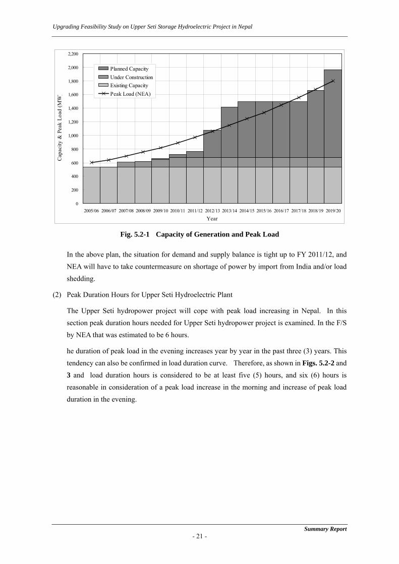
Fig. 5.2-1 Capacity of Generation and Peak Load
In the above plan, the situation for demand and supply balance is tight up to FY 2011/12, and NEA will have to take countermeasure on shortage of power by import from India and/or load shedding.
(2) Peak Duration Hours for Upper Seti Hydroelectric Plant
The Upper Seti hydropower project will cope with peak load increasing in Nepal. In this section peak duration hours needed for Upper Seti hydropower project is examined. In the F/S by NEA that was estimated to be 6 hours.
he duration of peak load in the evening increases year by year in the past three (3) years. This tendency can also be confirmed in load duration curve. Therefore, as shown in Figs. 5.2-2 and 3 and load duration hours is considered to be at least five (5) hours, and six (6) hours is reasonable in consideration of a peak load increase in the morning and increase of peak load duration in the evening.

Upgrading Feasibility Study on Upper Seti Storage Hydroelectric Project in Nepal
Summary Report - 22 -
0
100
200
300
400
500
600
1 3 5 7 9 11 13
Load
(MW
)
15 17 19 21 23
3 Dec. '03
8 Dec. '04
12 Jan. '06
5 hours
Fig. 5.2-2 Yearly Load Duration Curve(2004/05 and 2005/06)
Fig. 5.2-3 Daily Load and Duration Curve on 2013/14
5.3 Justification of Project observed from Power Development Scheme
(1) Examination observed from Aspect of Demand and Supply
NEA power system is faced on an unfavorable situation for tight demand and supply balance, and this will continue until FY 2012/13 even in the case that power plants listed in the power expansion plan are developed as scheduled. Power should be imported from India and/or the scheduled load shedding should be carried out, to cope with the power shortage. Demand and supply balance up to FY 2013/14 when the Project will be commissioned is shown in the Table 5.3-1.
Table 5.3-1 Demand and Supply Balance up to FY 2013/14 (Unit: MW)
05/06 06/07 07/08 08/09 09/10 10/11 11/12 12/13 13/14Peak Load 603 642 695 760 820 891 971 1057 1148Peaking and/or Install Capacity
583 587 659 669 713 762 806 1,115 1,455
Surplus power -20.5 -56 -36 -91 -107 -128 -165 58 307
However, this demand and supply balance includes uncertain factors as follows;
a. Peaking Capacity of supply side until FY2009/10 shows total of dependable output of each power plant in December to January in dry season estimated by NEA, but total of installed
0
100
200
300
400
500
600
700
1
646
1291
1936
2581
3226
3871
4516
5161
5806
6451
7096
7741
8386
Hours
Load
(MW
)
2004/05 2005/06
1,800 hours / 365 day= 4.9 = 5 hours

Upgrading Feasibility Study on Upper Seti Storage Hydroelectric Project in Nepal
capacity of the hydroelectric plants commissioned after FY 2010/11. Hence, it will be not possible to generate power with total output in dry season after FY 2010/11.
b. In drought year, the dependable output will become lower than that in the average year.
c. In the generation expansion plan shown in Table 5.3-1, the hydroelectric projects with about 1,070 MW in total capacity are to be developed until FY2013/14. The projects developed by NEA have only about 500 MW in install capacity, corresponding to 50% of the total. IPP projects are apt to be delayed in consideration of past progress, because commissioning date is not guaranteed in Power Purchase Agreement (PPA).
Therefore, 307 MW of reserve margin in FY2013/14 are not maintained in dry season and this project is important to cope with the peak load demand.
(2) Examination observed from Quality of Electricity
1) Power System Frequency
The power system frequency of the NEA power system is to be controlled to within 50 Hz +/- 1.0% (49.5–50.5 Hz) of the normal operation range. Although the system frequency is maintained within this range in daytime, based on actual records of daily maximum and minimum frequencies, it is difficult to maintain the frequency to within the normal operating range, and it is thus maintained to within 50 Hz +/- 2.5% (48.75 – 51.25 Hz) of the emergency operating range, as prescribed in the “Electricity Regulations, 1993” to cope with steep load increases/decreases during peak loading times. These operational circumstances for the power system frequency have the tendency of seeing the mean frequency gradually fall from July (rainy season) to February (dry season), while maintaining frequency over the rated value (50 Hz).
The system frequency of the NEA power system is controlled with plus system time on a year-round basis, even during peak load periods. The area controlled with plus system time is also supposed to be fairly large, which means that the NEA power system is consuming excess energy. NEA, by improving the power system frequency, will be able to save on fuel expenses for costly thermal power plants and enable effective hydropower generation.
This project is planned as a reservoir type hydropower plant, meaning this plant is both a useful and worthy means of securing the marginal supply capability for AFC resources, because this station incorporates both functions, namely the ability to respond to peak load featuring rapid increases within a short time and also to absorb frequency fluctuations. The power station is estimated to be capable of adjusting the power system frequency by around 1 Hz during the peak load time in FY 2014.
Summary Report - 23 -

Upgrading Feasibility Study on Upper Seti Storage Hydroelectric Project in Nepal
2) Power System Voltage
In addition, the NEA power system, from a power system voltage perspective can be summarized as follows:
- In the Kathmandu valley, it is difficult to maintain 132 kV of primary voltage on a year-round basis.
- The bus bar voltage within the power supply zones, is maintained at level exceeding the rated output.
In order to maintain well-controlled power system voltage, the power system voltage must be adjusted with reactive power and sufficient reactive power obtained at peak load periods on a year-round basis. This project will be able to evacuate reactive power at a rated output of around 80 Mvar to the power system, and this evacuation of reactive power will facilitate the power system operation in terms of maintaining the bus bar voltage at an appropriate voltage level at substations, both day and night, and throughout both the dry and wet seasons.
(3) Examination from the Aspect of Power System Operation
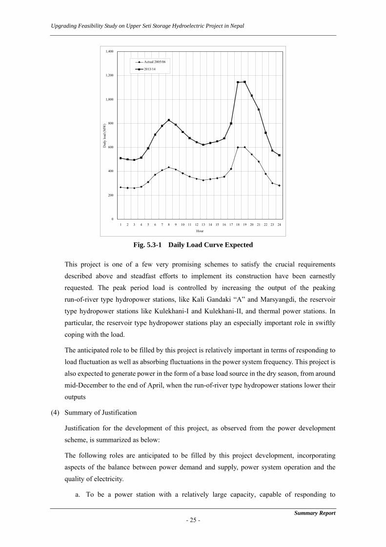
The most serious issue, with power system operation in mind, is the rapidly rising rate of increase in peak period loads; a phenomenon which is accelerating every year. This tendency is supported by the results of an analytical study for energy demand in the domestic category showing a high growth rate.
Based on the illustrated daily load curve for January 12, 2006 (see Fig. 4.3-2), when the maximum peak load was recorded, the load increases by about 180 MW in one hour from a system load of around 420 MW. In FY 2013/14 the peak load is forecast to be about 1,150 MW, and the rapid load increase of 180 MW in FY 2005/06 is presumed to rise to around 350 MW.
The system load factor of the NEA power system is supposed to gradually decline, especially based on the increase in domestic energy, which equates to a share of total energy demand of around 40%. This means that the load increase recorded on January 12, 2006 will further intensify in the period FY2013/14, as shown in Fig. 5.3-1.
Summary Report - 24 -
Upgrading Feasibility Study on Upper Seti Storage Hydroelectric Project in Nepal
Summary Report - 25 -
0
200
400
600
800
1,000
1,200
1,400
1 2 3 4 5 6 7 8 9 10 11 12 13 14 15 16 17
Hour
Dai
ly lo
ad (M
W)
18 19 20 21 22 23 24
Actual 2005/06
2013/14
Fig. 5.3-1 Daily Load Curve Expected
This project is one of a few very promising schemes to satisfy the crucial requirements described above and steadfast efforts to implement its construction have been earnestly requested. The peak period load is controlled by increasing the output of the peaking run-of-river type hydropower stations, like Kali Gandaki “A” and Marsyangdi, the reservoir type hydropower stations like Kulekhani-I and Kulekhani-II, and thermal power stations. In particular, the reservoir type hydropower stations play an especially important role in swiftly coping with the load.
The anticipated role to be filled by this project is relatively important in terms of responding to load fluctuation as well as absorbing fluctuations in the power system frequency. This project is also expected to generate power in the form of a base load source in the dry season, from around mid-December to the end of April, when the run-of-river type hydropower stations lower their outputs
(4) Summary of Justification
Justification for the development of this project, as observed from the power development scheme, is summarized as below:
The following roles are anticipated to be filled by this project development, incorporating aspects of the balance between power demand and supply, power system operation and the quality of electricity.
a. To be a power station with a relatively large capacity, capable of responding to

Upgrading Feasibility Study on Upper Seti Storage Hydroelectric Project in Nepal
fluctuations in load and absorbing fluctuations in power system frequency during peak times.
b. To be a power station capable of generating the power during the dry season, from mid-December to the end of April, via seasonal reservoir operation, not only during peak times but also non-peak load times as the base load, depending on the demand and supply balance.
c. To be a power station that is capable of continuing to generate a full output of at least five (5) hours during peak periods.
d. To be a power station that is capable of producing sufficient reactive power in order to maintain the bus bar voltage at substations in consideration of the irregular NEA power system.
e. To be a power station with the potential to save on costly fuel expenses incurred by thermal power plants
Summary Report - 26 -

Upgrading Feasibility Study on Upper Seti Storage Hydroelectric Project in Nepal
Summary Report - 27 -
6 HYDROLOGY AND SEDIMENTOLOGY
6.1 Outline
The Project site is located in the upper part of the Seti River, a tributary of the Trishuli River flowing in the central part of Nepal. The Seti River originates at the Annapurna (7,555 m height above sea level) of the Himalaya Mountains and joins the Madi River 2 km downstream from the Dam site after flowing about from north to south. The length of the Seti River from the origin to the Dam site is about 120 km, and a catchment area at the Dam site is 1,502 km2.
The Seti River basin belongs to a high mountain and a humid subtropical climatic zone. The NEA’s report states that the average annual precipitation in the project basin is 2,973 mm and it rains about 80% of it between June and September due to the influence of the southwest monsoon. The record of the Kharini Tar meteorological station located near the Project site states that the highest temperature is over 36°C from April through June as against the lowest one of approximately 5°C from January through February on average.
The Department of Hydrology and Meteorology (DHM), a subordinate organization of the Ministry of Environment, Science and Technology, carries out meteorological observations and river discharge measurements and gives NEA those data.
6.2 River Discharge
A new gauging station was set up 500 m downstream from the proposed Dam site, and river discharge measurement has been started since 2000. A measurement period is not so long as to calculate probable floods and annual energy production, so NEA converts river discharge data of gauging stations near the project site from 1964 to 1999 into those of the Dam site with the ratio of catchment area giving weight of annual precipitation as shown in Fig. 6.2-1 and Table 6.2-1. Average river discharge in the estimation period is 107.2 m3/sec.
70
80
90
100
110
120
130
140
196419
6519
6619
6719
6819
6919
7019
7119
7219
7319
7419
7519
7619
7719
7819
7919
8019
8119
8219
8319
8419
8519
8619
8719
8819
8919
9019
9119
Year
River Disch
arge
(m
3/se
c)
9219
9319
9419
9519
9619
9719
9819
99
Avg.5-year moving avg.
Fig. 6.2-1 Trend of Generated Average Annual River Discharge at Dam Site

Upgrading Feasibility Study on Upper Seti Storage Hydroelectric Project in Nepal
Table 6.2-1 Generated Average Monthly River Discharge at Dam Site (Unit: m3/sec) Month 1 2 3 4 5 6 7 8 9 10 11 12 Avg Year 1964 31.8 30.4 30.1 31.9 68.9 78.0 134.3 460.5 313.1 112.4 82.0 53.8 118.921965 34.0 29.5 29.7 32.7 36.3 151.0 293.5 368.5 190.3 62.6 46.9 31.3 108.861966 24.6 22.2 21.0 19.4 22.2 63.5 228.4 259.6 159.8 66.0 38.6 25.5 79.231967 20.6 20.7 20.1 22.8 24.5 57.8 231.3 213.2 185.8 77.2 43.5 33.8 79.281968 24.9 20.5 24.7 25.3 34.9 141.9 336.1 287.0 222.7 326.6 42.1 23.7 125.861969 18.3 14.6 15.2 15.0 16.6 34.4 128.0 315.0 264.0 79.5 40.3 26.1 80.581970 20.2 17.3 16.3 24.6 35.3 91.2 380.8 412.0 202.1 106.1 56.8 33.4 116.341971 23.7 18.7 18.8 29.1 39.6 187.7 291.2 300.6 212.8 145.7 67.7 40.0 114.621972 25.7 20.3 19.4 20.5 52.9 106.6 325.6 362.5 251.6 108.6 51.4 33.4 114.871973 25.1 17.6 18.0 25.8 39.2 176.3 244.0 389.0 265.3 259.4 74.4 39.1 131.101974 36.8 33.7 32.6 40.8 39.0 91.7 343.3 411.6 254.4 131.7 43.8 34.1 124.451975 33.0 32.1 30.2 22.8 24.0 84.9 427.0 328.4 305.5 139.2 54.1 30.4 125.971976 22.3 23.1 19.8 24.9 40.9 190.2 380.3 342.3 216.0 88.4 43.6 33.8 118.801977 22.7 20.4 20.7 30.2 46.8 92.4 288.5 409.0 248.3 111.8 74.8 43.3 117.401978 32.3 29.6 27.2 29.4 68.7 162.1 381.0 349.6 215.6 106.0 64.3 47.7 126.121979 37.7 33.7 29.8 37.7 51.9 84.7 315.0 447.0 239.4 107.2 57.5 34.6 123.001980 25.2 22.9 25.3 26.6 37.1 107.9 425.1 446.5 313.7 82.5 43.8 26.2 131.901981 18.2 14.9 15.6 28.7 40.1 95.9 400.6 376.5 242.7 97.0 50.2 36.9 118.091982 33.3 30.8 36.1 40.1 48.9 96.9 257.7 271.3 155.5 85.9 54.5 45.3 96.371983 39.8 36.6 35.3 34.5 46.7 72.8 210.4 270.5 276.7 143.2 54.7 35.6 104.741984 28.0 21.2 21.7 24.0 62.8 151.9 445.1 287.3 243.5 96.1 58.6 41.3 123.461985 36.9 33.5 33.0 39.1 61.1 114.9 333.4 197.5 202.9 126.2 56.5 36.0 105.901986 24.7 19.8 21.4 28.5 27.9 117.6 260.7 259.8 280.2 147.9 59.2 30.7 106.531987 23.5 20.4 21.4 23.6 31.2 72.2 280.0 279.5 183.6 87.3 54.2 39.2 93.011988 30.2 26.8 27.0 28.8 40.7 111.7 264.4 320.5 238.9 102.6 52.9 38.6 106.931989 33.9 27.8 27.8 30.5 59.4 146.6 251.7 310.7 240.2 113.9 53.8 36.4 111.061990 28.1 24.8 26.0 35.9 55.2 152.9 271.9 237.3 194.1 102.8 44.5 27.3 100.061991 20.0 17.6 16.8 20.3 33.4 114.9 281.0 320.4 250.2 117.2 56.3 39.0 107.251992 31.1 27.9 26.5 25.2 35.7 82.0 188.9 289.8 197.4 124.8 50.3 30.5 92.521993 23.2 20.6 14.5 14.7 30.0 97.8 218.4 321.3 215.4 122.4 56.8 33.3 97.371994 29.3 27.5 29.8 30.1 37.0 106.8 184.2 233.9 142.8 37.7 17.7 12.9 74.141995 10.5 9.9 11.3 11.9 28.3 255.9 314.9 193.9 175.9 129.9 85.9 52.7 106.751996 30.1 21.6 30.9 31.0 37.6 69.2 227.0 319.8 252.2 107.6 45.8 31.5 100.371997 27.2 24.0 28.4 32.6 38.4 74.9 229.6 258.9 141.6 61.8 35.0 33.1 82.121998 24.2 21.5 24.9 29.1 48.7 149.3 288.1 452.6 207.3 64.2 35.6 26.0 114.291999 21.3 18.5 17.0 18.8 34.8 93.1 264.8 238.7 174.2 67.4 23.1 15.3 82.24Avg. 27.0 23.7 24.0 27.4 41.0 113.3 286.8 320.6 224.3 112.4 52.0 34.2 107.24
Summary Report - 28 -

Upgrading Feasibility Study on Upper Seti Storage Hydroelectric Project in Nepal
6.3 Flood
Based on maximum daily discharge at No. 430 gauging station from 1964 to 1984, frequency analysis is carried out using the Gumbel, Log-normal and Log-Pearson distributions. The results are summarized in Table 6.3-1.
Table 6.3-1 Probable Flood (Unit: m3/sec)
Return Period Gumbel Log-Normal Log-Pearson 2 994.6 934.5 569.8 5 1,565.0 1,434.9 889.8
10 1,942.8 1,795.4 1,140.8 20 2,305.1 2,160.6 1,412.2 50 2,774.1 2,661.3 1,811.8
100 3,125.6 3,057.7 2,150.7 200 3,475.5 3,472.4 2,525.7 500 3,937.5 4,050.8 3,083.8
1,000 4,286.6 4,513.0 3,558.9 2,000 4,635.6 4,779.0 4,546.1 5,000 5,097.0 5,675.6 5,265.4
10,000 5,445.7 6,217.3 5,529.6
As it is considered that this project will play a very important role for economic and social development of Nepal, it will be appropriate to adopt the Probable Maximum Flood (PMF) in the design of the Dam. PMF is defined as the flood that may occur under the theoretical combination of the most severe meteorological and hydrological conditions.
PMP is generally classified as non-orographic and orographic precipitations. The form of precipitation in the Seti River basin is considered to have typical orographic characteristics, because it is observed that precipitation caused by monsoon from the south is concentrated at the southern slope of the Himalaya Mountains, while precipitation in the plateau as well as north of the Himalaya Mountains is extremely small. So PMP caused by orographic precipitations is calculated.
A flood hydrograph synthesized with the daily average value of PMP and base flow of 126 m3/s calculated from the discharge of 95% probability during rainy season (July – September) are added. PMF discharge at the Dam site is estimated to be 7,251+126 = 7,377 m3/sec as shown in Fig. 6.3-1.
Summary Report - 29 -

Upgrading Feasibility Study on Upper Seti Storage Hydroelectric Project in Nepal
Summary Report - 30 -
0
1,000
2,000
3,000
4,000
5,000
6,000
7,000
8,000
0 24 48 72 96 120 144 168 192 216
TIME (hour)
Dischar
ge (m
3/se
c)
240
0.0
10.0
20.0
30.0
40.0
50.0
60.0
70.0
80.0
7,251m3/sec
Rainfa
ll (c
m)
34.2 cm
PMF = 7,251+126 (Baseflow) = 7,377 m3/sec
Fig. 6.3-1 Synthesis of Unit Hydrographs
An effective catchment area, catchment area in connection with PMF, and PMF discharge per an effective catchment area of the dam projects on rivers originating from the Himalaya Mountains in Nepal and India are compared and the value of PMF discharge of the Project is judged to be reasonable.
6.4 Sedimentology
The Seti River basin is dotted with sources of sediment and specific sediment yield of the River is larger than other project areas in Nepal. There is little possibility that a lot of sediment may be washed away into the Reservoir at once considering a positional relation between sources of sediment and the Reservoir. Simulating the riverbed fluctuation after the NEA’s Feasibility Study, the Reservoir is to be filled with sediment about 40 years after completion, which tells that sediment flushing facilities are indispensable to maintenance of the effective Reservoir capacity. Considering measures against sedimentation, the Study team judges that flushing which uses tractive force of natural river flow is suitable for the Project site. Flushing operation is carried out in the former half of the rainy season lowering the Reservoir water level.
If sediment flushing operation is carried out every year in the Reservoir with the dimensions decided in Chapter 10 using river discharge from 1964 to 1999 three times repeatedly, a riverbed fluctuation in 108 years is as shown in Fig. 6.4-1.

Upgrading Feasibility Study on Upper Seti Storage Hydroelectric Project in Nepal
Summary Report - 31 -
300
320
340
360
380
400
420
440
0
Ele
vation (m
)
5,00010,00015,00020,00025,00030,000
Distance from Dam Axis (m)
Original riverbed
18 years after
36 years after
54 years after
72 years after
90 years after
108 years after
FSL 415.00
FSL415.00
Fig. 6.4-1 Riverbed Profile of Reservoir with Sediment Flushing Gates
Measures against sedimentation of the Reservoir studied in this chapter are concluded as follows.
(1) The sill elevation of sediment flushing facilities is decided as EL. 320.00 m considering topography of the Dam site, the riverbed elevation and the positional relation between the facilities and the spillway. If the sill elevation is raised up by 10 m, a riverbed level rises by the difference of the sill elevation, and sediment volume in the Reservoir increases. It is necessary to install sediment flushing facilities at the lowest possible elevation.
(2) The riverbed fluctuation is simulated when the flushing operation is carried out every year, every two years and every three years. The simulation results tell that sediment advances year by year without the yearly sediment flushing operation and that the operation shall be carried out every year in order to maintain reservoir function as long as possible.
(3) It is desirable that the sediment flushing operation period is prepared as long as possible. In this study sediment flushing operation is to be carried out from June 20 to July 31 lowering the reservoir water level to the sill elevation of sediment flushing facilities considering quick restoration of the Reservoir water level and minimization of a decrease in energy production caused by the operation. The simulation result tells that sediment deposits in the reservoir is stored so much that the reservoir does not function sufficiently, if the sediment flushing operation period is made shorter than the above dates.
(4) The above sediment flushing operation period is set up only to confirm the validity of the sediment flushing operation and the period shall be adjusted to a pattern of river discharge in each year in the operation stage. For example, it is recommended that a sediment flushing operation period should be adjusted to a degree of sedimentation in the Reservoir measured by a periodical survey in a maintenance stage.
Upgrading Feasibility Study on Upper Seti Storage Hydroelectric Project in Nepal
(5) Rating curves of the River water level near Bhimad Bajar tell that the progress of sedimentation does not cause an increase in the river water level and the level is almost the same as that before the Dam is constructed.
(6) The riverbed fluctuation is simulated when a 100-year probable flood occurs. The simulation result tells that the flood hardly affects the riverbed profile.
(7) The simulation method of riverbed fluctuation used in this study cannot estimate three-dimensional sediment distribution near the inlet of the sediment flushing facilities. It is recommended that a hydraulic model test should be carried out during the detailed design stage to decide detailed shapes of the facilities.
In this study, riverbed fluctuation is estimated, and measures are taken in a feasibility study stage. The WB proposes a life cycle sediment management method of a circular type to compare some feasible management methods of reservoir sedimentation in planning, design, construction and operation stage, and not a linear management method to carry out a management method of reservoir sedimentation decided during a planning stage until a reservoir ends its life. It is necessary to choose the optimum management method out of the feasible management methods of reservoir sedimentation from technical and economic point of view and to carry out it during a maintenance stage in response to quantity of sediment and progress of sedimentation in the reservoir and based on the above idea.
Summary Report - 32 -

Upgrading Feasibility Study on Upper Seti Storage Hydroelectric Project in Nepal
7 GEOLOGY
7.1 Outline of the Geology of the Project Area
The Project area is located in the Lesser Himalayan zone among five tectonic provinces of Nepal. Pre-Cambrian to Paleozoic Nourpul formation, Dhading Dolomite and Benighat slate belonging to Nawakot group are distributed in the area. Nourpul formation and Dhading dolomite are late Pre-Cambrian to early Plaeozoic in age and are composed of dolomite, slate, phyllite, quartzite, dolomitic quartzite and quarzitic phyllite. Benighat slate is late Paleozoic in age and consists of slate, phyllite, calcareous slate and a small amount of quartzite. These strata trend E-W to WNW-ESE, namely parallel to the Seti River, and dip southward.
7.2 Site Geology
(1) Reservoir
The length of the reservoir is approximately 18 km. The reservoir from the dam site to 11 km upstream of the dam site forms a steep valley; the inclination of the slope of both banks of the reservoir is about 40 degree in this area. On the other hand, the upstream area of the reservoir shows the relatively gentle topography with several terrace plains in both banks.
Reservoir area is composed of Pre-Cambrian to Paleozoic dolomite, slate, phyllite and Quaternary deposit of terrace deposit, talus deposit and recent river deposit. Dolomite is distributed in the left bank from the dam site to the middle part of the reservoir with the strike of E-W, parallel to the Seti River, and dip of 40 to 60 degree to south. The prominent karst phenomenon or karst topography is not confirmed in this dolomite area. Slate and phyllite are distributed in the right bank from the just upstream of the dam site to the middle part of the reservoir and in the both banks of the upstream area. They strike E-W and dip 40-60 to south in the same direction as the dolomite.
1) Watertightness of the reservoir
The narrow saddle or thin ridge, which has the possibility of the leakage to the adjacent drainage basin, is not observed in the reservoir area. Judging from the topographic and the geologic condition mentioned above, it is considered that the waterthigtness of the reservoir is assured.
2) Stability of the slope
Large landslide, which causes damage to the reservoir and surrounding environment, is not observed in the reservoir area. However, the terrace deposits form the vertical cliffs in the upstream area of the reservoir because of the erosion by the Seti River. These cliffs are not completely stable under the present situation. It is presumed that the cliffs will be collapsed progressively and they will move toward the mountainside keeping their vertical
Summary Report - 33 -

Upgrading Feasibility Study on Upper Seti Storage Hydroelectric Project in Nepal
shape. There is a possibility that the erosion or strength reduction of the terrace deposit is accelerated by the infiltration of the reservoir water. The vertical cliffs of the terrace are found in many places from Bhimad Bazzar to Jaruwapan about 6 km downstream. The countermeasure or mitigation against the erosion is necessary for these cliffs. The details of the method and the extent of them should be examined based on the detailed topographic map and geologic map at D/D stage.
(2) Dam
The dam site is located in the Seti River about 2 km upstream of the confluence of the Seti River and the Madi River, and the both banks of the dam site form steep slopes of 70 to 80 degree. The right bank of the dam is composed of the narrow ridge of EL.500 m to 550 m which extends in E-W direction. The width of the right bank ridge at FSL, EL.415 m, is 150 m to 200 m. The left bank of the dam is located at the east end of the ridge of EL.1, 000 m which extends along the left bank of the reservoir. The width of the river is about 30 m and the width of the valley at FSL, EL.415m, is about 90 m at the dam axis.
Dam foundation is composed of Late Pre-Cambrian to early Paleozoic grey to dark grey dolomite as shown in Fig.7.2-1 and Fig.7.2-2. The dolomite is hard and thick bedded in general, but the phyllitic dolomite layers of 1 to 2 m thickness, which tends to fine fragments, are intercalated in some places. These layers strike WNW-ESE to E-W and dip 45 to 60 degree to south. Weathering degree of the foundation rocks is low in general; the weathered zone of 1 to 5 m in thickness, which shows the brown color caused by oxidation, is found only in the high portion of both banks. Large fault is not confirmed in the dam site, but several small faults of 20 to 200 cm in width are found in places.
1) Evaluation of the Foundation Rock
The left abutment of the dam is composed of the good rock of CH class and B class, and the river bed consist of the relatively good rock of CH class and CH~CM class in parts. On the other hand, the right abutment consists of the jointed rock in general except for the lower portion near the riverbed. However, as the result of the B-12 hole the relatively good rock of CH~CM class is distributed in the portion deeper than 30 m from the ground surface in the right bank. Considering the above mentioned geological condition, the foundation rock of the dam site is judged to have a sufficient bearing capacity for the foundation of the concrete gravity dam of 140 m in height. However, the rock condition of the dam foundation should be confirmed by the exploratory adit, and the mechanical properties of the foundation rocks should be clarified by the in-situ tests in the adit at D/D stage.
Summary Report - 34 -
Upgrading Feasibility Study on Upper Seti Storage Hydroelectric Project in Nepal
2) Permeability and Groundwater Level
The high permeability zone of Lu>10 is the portion from the ground surface to 70 m depth in the left bank and the potion from the ground surface to 40 m depth in the right bank. The area deeper than those depth shows low permeability of Lu=2~10 or Lu<2 except for a part of the right bank. The permeability of the riverbed is high to the depth of 30 m, but the deeper portion is low permeability of Lu=1~4. The permeability of the foundation rock in the dam site is presumed to be controlled by the discontinuity planes such as joints, and the solution cavities seems to have a little effect on the permeability of the foundation rocks. Therefore, it is considered that the commonly used cement grouting can be applied to the foundation treatment for the high permeability zone.
Although it is confirmed that the groundwater level is rising up toward the mountain side in both banks, the groundwater level is located in the deep portion of both banks, which is 70 m lower than FSL. Accordingly, the groundwater level in the mountain of the both banks should be investigated at D/D stage. Drillings from the adit mentioned in a) or from the ground surface for the investigation of the groundwater level are recommended.
(3) Waterway and Powerhouse (Option-II)
The intake, the underground powerhouse and the outlet of tailrace of the option-II are located in the right bank ridge which extends in E-W direction.
The waterway and the underground powerhouse are composed of same dolomite as dam foundation. As the result of the drill hole BP-1, the arch portion of the underground powerhouse consists of the relatively jointed rock of CM class, and the lower portion of the powerhouse cavern is composed of highly jointed rock of CL class. This rock mass condition is classified to “Very poor rock” to “Poor rock” of the RQD classification and according to the RMR (Rock Mass Rating) classification, the arch portion is evaluated as “Fair rock” and the lower portion of the cavern is evaluated as “Poor rock”.
As the result of the BH-1 hole at the intake site, the foundation rock from the ground surface to 39 m depth consists of good rock of CH class. It is judged that the intake shaft will be excavated without big trouble. Thick talus deposit and the landslide are not found in the slope where the intake is planned.
Thick talus deposit and the river deposit are distributed in the outlet of tailrace site, and the basement of the outlet is located in the river deposit. The excavated slope of which height is about 20 m consists of talus deposit.
(4) Waterway and Powerhouse (Option-III b)
In the option-III b, the intake is located in the right bank slope about 250 m upstream of the dam axis, and the waterway will be excavated from the intake site for 1.5 km in WNW-ESE direction.
Summary Report - 35 -

Upgrading Feasibility Study on Upper Seti Storage Hydroelectric Project in Nepal
The waterway tunnel crosses the ridge of EL.600m~1,000m, and the rock cover of the waterway tunnel is 200~650 m and that of the underground powerhouse is 300~400 m.
The tunnel route is composed of Phyllite including salty phyllite, dolomite, slate, and the underground powerhouse consists of dolomite as shown in Fig.7.2-3. Although the boundary between phyllite and dolomite is presumed to be a fault in the reservoir area, which runs straightly in E-W direction, any phenomenon, which suggest a large fault geologically or topographically, are not observed on the tunnel route of the right bank. The strike of phyllite is almost parallel to the axis of the tunnel and dipping is 45 to 50 degree. If a seam or fractured zone along the bedding plane of phyllite is predominant, it is not favorable condition for the tunnel excavation, but it dose not bring on the significant difficulties of the tunnel excavation.
Penstock and underground powerhouse site are composed of dolomite. The thickness of dolomite layer near the underground powerhouse site is estimated to be 200 m, and the width of the dolomite layer in the horizontal plane is about 300 m. The dolomite layer has enough wide distribution for the layout of the underground powerhouse and penstock. As the observation results of the outcrops, dolomite in this area is hard and relatively a few jointed, and it is evaluated as a good rock condition. However, the rock condition of the underground powerhouse site is not directly confirmed. At present, NEA is carrying out the investigation drillings in the vicinity of the underground powerhouse site. Accordingly, it is necessary to to examine the investigation drilling results carried out by NEA and to confirm the rock condition and the distribution of dolomite by the exploratory adit and the investigation drillings in the adit at D/D stage.
(5) Construction Material
The investigations of the concrete aggregate had been carried out for the river deposits of the Seti River and the Madi River by NEA in 2001 and 2005.
According to these investigation results, the river deposit of the Seti and Madi River satisfy the standard of ASTM and JIS fro the specific gravity, absorption, soundness and abrasion loss. These materials contain a fine material in some degree. However, it is considered that these materials can be used for the concrete aggregate in selecting the area of few fine materials and washing out the fine components while producing the concrete aggregate. And the necessary volume of the concrete aggregate for the project is estimated to be secured. The result of Alkali-aggregate reactivity test indicates the deleterious aggregate for the river deposit and dolomite near the dam site. However, the chemical method of Alkali-aggregate reactivity test is not suitable for the carbonate rock such as dolomite in many cases. Therefore, the detailed investigations including the Mortar-bar method should be carried out and the possibility of the Alkali-aggregate reactivity of the dolomite should be examined at D/D stage.
Summary Report - 36 -

Upgrading Feasibility Study on Upper Seti Storage Hydroelectric Project in Nepal
The excavated rock of the dam foundation may be utilized for the concrete aggregate instead of the river deposit. The investigation results up to now shows that dolomite of the dam foundation is almost same quality to the river deposit, so it is assumed that the dam foundation rock can used for the concrete aggregate. As for the Alkali-aggregate reactivity, the detailed investigation is necessary in the same manner as the river deposit.
Summary Report - 37 -

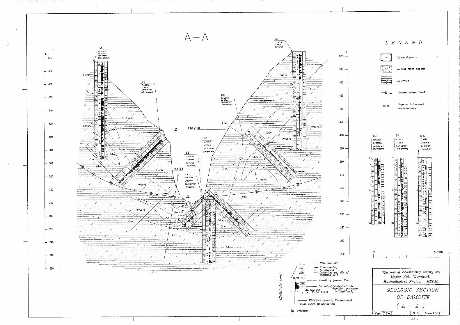

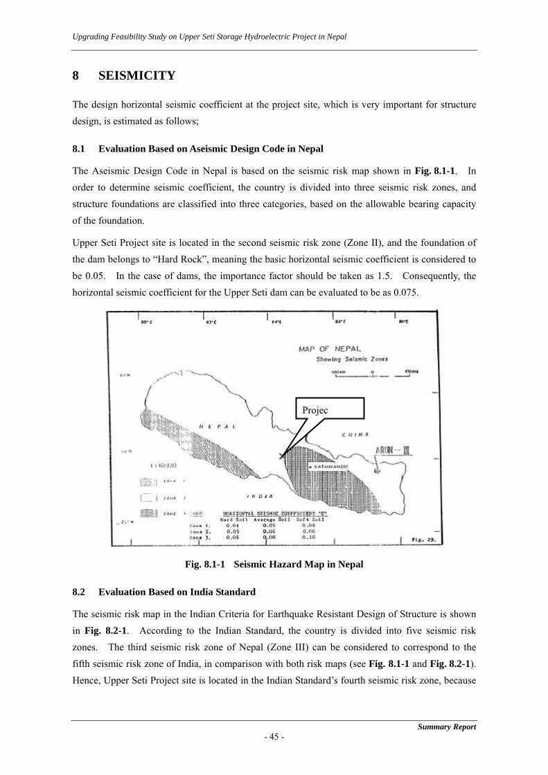
Upgrading Feasibility Study on Upper Seti Storage Hydroelectric Project in Nepal
8 SEISMICITY
The design horizontal seismic coefficient at the project site, which is very important for structure design, is estimated as follows;
8.1 Evaluation Based on Aseismic Design Code in Nepal
The Aseismic Design Code in Nepal is based on the seismic risk map shown in Fig. 8.1-1. In order to determine seismic coefficient, the country is divided into three seismic risk zones, and structure foundations are classified into three categories, based on the allowable bearing capacity of the foundation.
Upper Seti Project site is located in the second seismic risk zone (Zone II), and the foundation of the dam belongs to “Hard Rock”, meaning the basic horizontal seismic coefficient is considered to be 0.05. In the case of dams, the importance factor should be taken as 1.5. Consequently, the horizontal seismic coefficient for the Upper Seti dam can be evaluated to be as 0.075.
Projec
Fig. 8.1-1 Seismic Hazard Map in Nepal
8.2 Evaluation Based on India Standard
The seismic risk map in the Indian Criteria for Earthquake Resistant Design of Structure is shown in Fig. 8.2-1. According to the Indian Standard, the country is divided into five seismic risk zones. The third seismic risk zone of Nepal (Zone III) can be considered to correspond to the fifth seismic risk zone of India, in comparison with both risk maps (see Fig. 8.1-1 and Fig. 8.2-1). Hence, Upper Seti Project site is located in the Indian Standard’s fourth seismic risk zone, because
Summary Report - 45 -
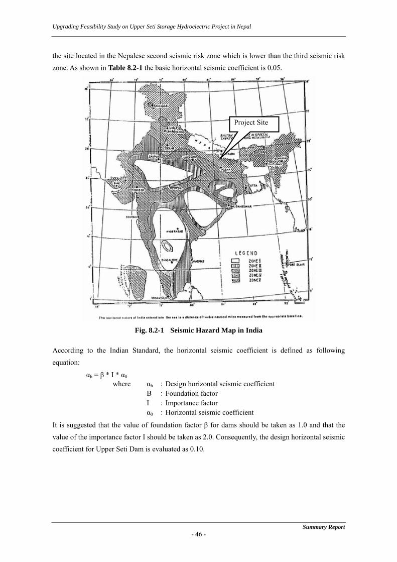
Upgrading Feasibility Study on Upper Seti Storage Hydroelectric Project in Nepal
the site located in the Nepalese second seismic risk zone which is lower than the third seismic risk zone. As shown in Table 8.2-1 the basic horizontal seismic coefficient is 0.05.
Project Site
Fig. 8.2-1 Seismic Hazard Map in India
According to the Indian Standard, the horizontal seismic coefficient is defined as following equation:
αh = β * I * α0 where αh :Design horizontal seismic coefficient Β :Foundation factor I :Importance factor α0 :Horizontal seismic coefficient
It is suggested that the value of foundation factor β for dams should be taken as 1.0 and that the value of the importance factor I should be taken as 2.0. Consequently, the design horizontal seismic coefficient for Upper Seti Dam is evaluated as 0.10.
Summary Report - 46 -

Upgrading Feasibility Study on Upper Seti Storage Hydroelectric Project in Nepal
Summary Report - 47 -
Table 8.2-1 Basic Seismic Coefficient in Indian Seismic Hazard Region
Seismic hazard region Basic horizontal seismic efficient V 0.08 IV 0.05 III 0.05 II 0.02 I 0.01
8.3 Evaluation of Maximum Acceleration
Seismic data used in the Study are based on those from 1994 to 2004 by National Seismological Center in Nepal and those from 1905 to 1995 by the NOAA (National Oceanic and Atmospheric Administration), United States Department of Commerce. The above data files include details of around 4,000 earthquakes which had their epicenters located within a 1,000 km in radius from the Upper Seti Project site (84o 15’ 30” in East Longitude and 27o 57’ 14” in North Latitude).
The maximum acceleration was calculated by using four attenuation models and the above seismic data for several return periods. Table 8.3-1 summarizes the results of estimation of the maximum accelerations due to historical earthquakes and of probability analysis.
Table 8.3-1 Summary of Maximum Acceleration Estimation at the Upper Seti Dam Site Date Location LAT(N) Long(E) M R Depth D Eq.(1) Eq.(2) Eq.(3)
18970612 Assam 22.5 91.8 8.7 1036.04 1.6 1036.04 1.14 14.33 1.7219050404 Kangra 33 76 8.6 1077.32 19 1077.49 0.98 12.78 1.4919081212 Burma 26.5 97 7.5 1427.57 1427.57 0.23 4.42 0.3919180708
Eq.(4) Remarks1.140.980.23
Assam 24.5 91 7.6 843.22 843.22 0.71 9.20 0.9919340112 Bihar 26.5 86.5 8.4 297.43 297.43 9.73 55.68 9.9619350530 Quetta 29 66.7 7.6 1958.00 11 1958.04 0.14 3.14 0.2619470729 NE Assam 28.5 94 7.9 1086.12 30 1086.53 0.55 8.08 0.8419500815
0.719.730.140.55
Assam 28.5 96.7 8.7 1386.31 1.526 1386.31 0.65 9.88 1.08
19540904 28.3 83.8 6.6 59.188 30 66.357 28.75 90.75 26.07
19960127 28.067 84.267 4.5 12.63 22 25.37 31.66 51.35 22.68
20010716 27.967 84.717 5.9 51.08 20 54.86 23.70 69.07 20.21
32.53 78.50 23.0442.97 91.54 28.1753.90 103.48 32.95
21.3023 75.2575 20.629326.943 87.4151 24.9746
32.6204 98.4988 28.9939
HistoriclDamaging
Earthquake
Near FieldEarthquakes
aroundSite
Return Period (year)
50
Probability (%)50 98.0%100 99.0%200 99.5%
98.0%100 99.0%200 99.5%
0.65
59.29 Max data
17.67
21.51
38.7245.5051.61
47.595656.9454
65.504
Main Curve
Reference Curve
To convert the maximum acceleration of earthquake motion into the design seismic coefficient, the following method is applied:
eff = R * Amax / 980 αeff : Effective design seismic coefficient R : Reduction factor
(The empirical value of R is approximately 0.55 to 0.65)
Reasons to consider R are described below;
- The static analysis method is that to evaluate the stresses and deformations by inputting the static inertia force to analytical model as earthquake force. In other words, the static analysis method can be considered a kind of dynamic analysis method with involving the input of the harmonic waves of frequency = infinite as a design input motion or earthquake force.

Upgrading Feasibility Study on Upper Seti Storage Hydroelectric Project in Nepal
Accordingly, if R is not considered, such method overestimates the design seismic coefficient. - Consideration of R was proposed based initially on empirical knowledge. However, similar
results have been also reported in studies on dynamic and static analysis.
The horizontal seismic coefficient based on the above method is shown in Table 8.3-2 and is estimated as 0.06.
Table 8.3-2 Seismic Coefficient Based Upon Maximum Acceleration
Estimated Value Basis of Estimation R = 0.6 The estimated maximum acceleration by the statistical analysis is
controlled by near-field earthquakes. Near-field earthquakes→Excell in high frequency→High reduction
Amax = 97.12 gal a. Maximum acceleration of historical earthquakes by attenuation models
90.75 gal on September 4, 1954 by Eq. (2) b. Statistical Analysis 103.48 gal:by Eq. (2) Amax is estimated as the average of a. to b.
αeff = 0.06 αeff = R*Amax / 980 = 0.06
8.4 Evaluation of Maximum Acceleration based on the Seismic Hazard Map of Nepal
The Seismic Hazard Map of Nepal, as shown in Fig. 8.4-1, was obtained during Site survey. According to this map, the Maximum Acceleration at the project site can be evaluated, and thus the value is evaluated to be as 230 gal.
Based upon this, the horizontal seismic coefficient based on the method as shown in (3) is shown below and is estimated to be 0.15.
eff = R * α = R * Amax / 980 = 0.6 * 230 / 980 = 0.1408
Summary Report - 48 -
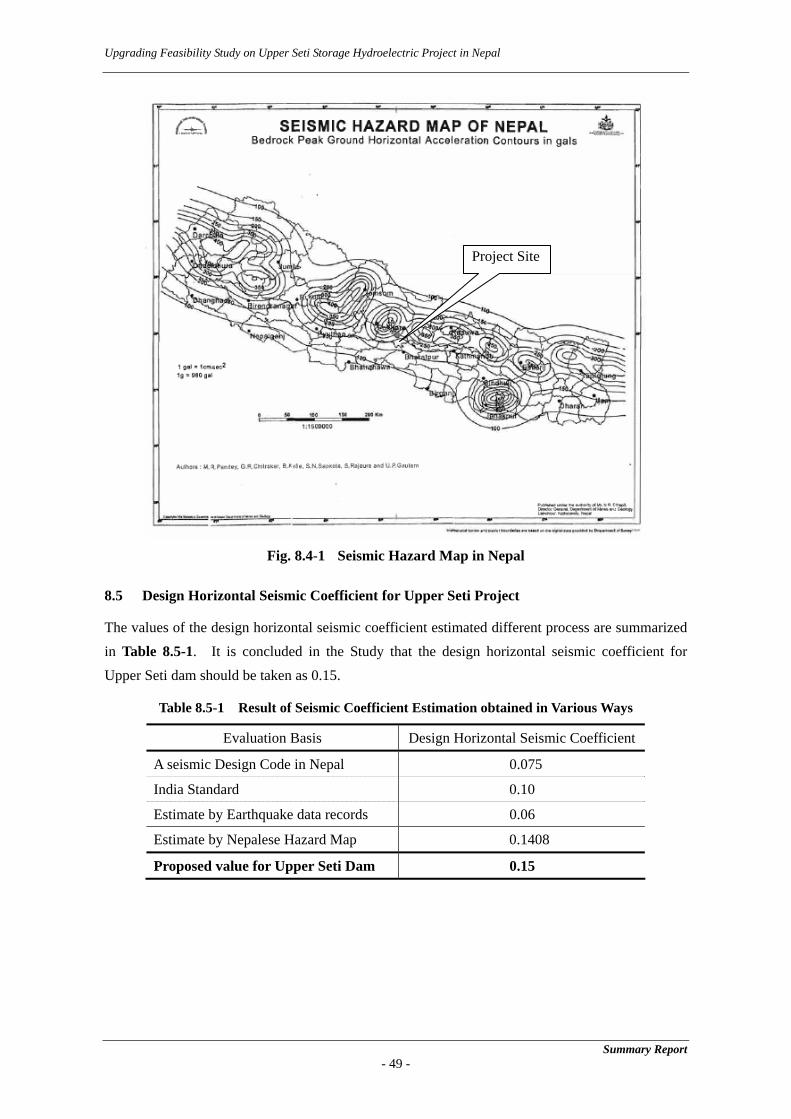
Upgrading Feasibility Study on Upper Seti Storage Hydroelectric Project in Nepal
Summary Report - 49 -
Fig. 8.4-1 Seismic Hazard Map in Nepal
8.5 Design Horizontal Seismic Coefficient for Upper Seti Project
The values of the design horizontal seismic coefficient estimated different process are summarized in Table 8.5-1. It is concluded in the Study that the design horizontal seismic coefficient for Upper Seti dam should be taken as 0.15.
Table 8.5-1 Result of Seismic Coefficient Estimation obtained in Various Ways
Evaluation Basis Design Horizontal Seismic Coefficient
A seismic Design Code in Nepal 0.075
India Standard 0.10
Estimate by Earthquake data records 0.06
Estimate by Nepalese Hazard Map 0.1408
Proposed value for Upper Seti Dam 0.15
Project Site

Upgrading Feasibility Study on Upper Seti Storage Hydroelectric Project in Nepal
9 ENVIRONMENTAL IMPACT ASSESSMENT
9.1 Review of the Existing EIA Report
NEA carried out EIA for the Upper Seti Hydropower Project in accordance with the Nepalese regulations concerned and a draft EIA submitted to Department of Electricity b Development (DOED) in July, 2004. As of May 2007 it is under appraisal by the Ministry of Water Resources.
The Study Team conformed, in May 2007, the NEA’s intention regarding revision of the existing EIA as follows:
- NEA and the ministries concerned recognize that the data quoted in the existing EIA have become out of date and that the supplementary EIA include surveys, impact assessments, and proposals on mitigation measures which the existing EIA did not cover.
- For the above reason, NEA will modify the existing EIA based on the supplementary EIA, after the final report is submitted to NEA. After the modification, NEA will submit the revised EIA to DOED for appraisal, and the EIA will be checked and reviewed by MOWR and MOEST.
The existing EIA was reviewed by the Study Team earlier during Phase 1 and generally found compatible with the Nepali standards for the physical and biological environmental impacts and management and monitoring plans. The existing EIA, however, does not comply with international standards for natural environmental aspects, especially as outlined in the JICA Guidelines for Environmental and Social Consideration (the JICA Guidelines) due to inadequacies in coverage relating to some subjects.
The background descriptions, impact assessments and mitigation, management and monitoring measures are lacking to a large degree for some aspects such as Sedimentation in the reservoir and flushing of sediments from the reservoir, and downstream effects. It is to be noted that descriptions on the fisheries aspects are adequate but the options for mitigation required reviewing. All of the short comings of the original NEA EIA were adequately addressed by the Supplemental EIA.
Regarding social environment, the adverse impacts predicted are of very general nature not sufficient to assess the gravity of socio-economic and cultural impacts. Although a range of mitigation and enhancement measures are proposed, the following information is inadequate.
- As recommended in the existing EIA report, the Acquisition, Compensation and Rehabilitation Plan (ACRP) need to be developed.
- Except for the training packages, the amount allocated for environmental mitigation and enhancement measures are lump sum. The more detailed design for mitigation measure is required including where these mitigation measures are to be implemented for whom.
Summary Report - 50 -

Upgrading Feasibility Study on Upper Seti Storage Hydroelectric Project in Nepal
9.2 Supplemental EIA by the JICA Study Team
The Supplemental EIA scoping was drafted based on the use of the Leopold Matrix in collaboration with NEA. As per JICA Guidelines, it was finalized through discussions and consultation with local stakeholders in the 1st stakeholder Meetings held in Damauli and Kathmandu on June 2 and 7 2006 respectively. The plan for supplementary surveys has been established as below
(1) Natural Environmental Studies
1) Examination of the eutrophication potential of the reservoir 2) Study on aquatic ecology and fishery aspects 3) Study on vegetation and forestry 4) Study on wildlife resources 5) Assess impacts of proposed alterations to project design and operations 6) Study for watershed management
(2) Socio-economic and Cultural Environmental Impact
- Socio-economic survey targeting the affected people - Preparation of the framework of Resettlement Plan (RP) - Assessment of the impacts on social and cultural aspects - Assessment of the impacts on vulnerable groups - Preparation of the Social Action Plan - Initial Environment Examination of transmission line routes - Preparation of the framework and revised costs for EMP
9.3 Natural Environment Impact Assessment
9.3.1 Mitigation Measures for Physical Environment
Based on the supplemental survey results, environmental impacts were assessed, and mitigation measures were proposed with costs. The following are principal mitigation measures:
(1) Construction Phase
Avoiding land use changes completely is not possible on the condition of the storage type hydropower project. However, selection of lower reservoir Full Supply Level could minimize existing land use changes.
The impact on the land use in the Project Facility Area can be mitigated by selecting the layout of the project facilities such as the alignment of the access road. To minimize the impact, the JICA Study Team examined the layout of the project facilities, especially the construction facilities, based on the GIS Map and discussed it with NEA at site.
Summary Report - 51 -

Upgrading Feasibility Study on Upper Seti Storage Hydroelectric Project in Nepal
Cost for the proposed mitigation measures during construction for physical environmental impact was estimated as NRs. 43.1 million (US$ 0.6 million).
(2) Operation Phase
1) Reservoir Shoreline Failure
It is likely that the reservoir Full Supply Level of 415 m and at higher elevation would aggravate the local landslides present throughout the upper reservoir area. It is proposed that the area requiring protection would be delineated during the detailed design. In the meantime it is estimated that the following actions should be undertaken:
a. Completion of protection embankment works with concrete blocks cover in the vicinity of Bhimad Bajar
b. Land acquisition program and stabilization of erosion prone in the risk zone area from Full Supply Level to 10 m high above
c. Selective planting of ground cover and trees at the base of areas susceptible to erosion in tributary stream leading into the Seti River
d. Land acquisition program and stabilization of erosion prone areas with suitable tree species in the vicinity of the Wantang Khola, the Pedhi Khola and Tutuwa
Cost for Item a is included into the civil works. Cost for items b, c, and d, land acquisition cost is estimated in the social in the social environment part and the costs for the bio-engineering works are included in the biological environmental cost.
2) Environmental Flow
The existing EIA recommended an annual environmental flow of 2.4 m3/s, which determined from the 10% of the minimum monthly average flow with reference to the method applied in the Kaligandaki A Project. The length of the dewatering area is only 2 km between dam site and the confluence with the Madi River, and the environmental flow proposed by NEA is likely to be reasonable range in comparison with the Japanese Guideline.
However, impacts on the river’s aquatic ecology and fish resources are unavoidable in the section of the Seti River immediately downstream of the dam and must be mitigated to the fullest extent possible.
3) Measures for Eutrophication
As a result of water quality test, the concentration of the nutrient input from the upstream of the reservoir is high and the there is high possibility of the reservoir eutrophication in future. Though the further detail investigation is required to establish the concrete measures, it is proposed that the installation of the fraction fence is most attractive
Summary Report - 52 -

Upgrading Feasibility Study on Upper Seti Storage Hydroelectric Project in Nepal
measures from the view point of the low cost and easy maintenance. The cost for fraction fence is estimated as US$ 0.9 million.
4) Downstream Effects
It is estimated to be as NRs 3.8 million (US$ 53,000) for the costs to protect the downstream communities and the costs for the prevention of accidents due to sudden surge of water twice a day in the Seti River immediately downstream and with flushing flows in the sector downstream of the dam.
9.3.2 Framework of Watershed Management Plan
To minimize the risks of sedimentation and its implication on the reservoir dead and live storage capacity, watershed management programs targeting on the reduction of erosion rates in the Seti watershed upstream reservoir dam is desirable.
The sediment source study in the Seti watershed of upstream dam indicates high sediment source areas in the northern part of the Seti watershed, 40 - 50 km away from the reservoir. Though, these sediments are conveyed as sediment load to the reservoir area by the flow in the river network, only a part of the sediment material travel up to reservoir in the short period.
it is proposed to provide small-scale civil engineering and bio-engineering measures of slope protection in the areas upstream from Bhimad to Pokhara. The cost is estimated as NRs. 111.5 (US$ 1.57 million).
The river bed erosion in the downstream of tailrace outlet does not have significant impact on the socio-economy of the area since the river course forms narrow steep gorge
9.3.3 Mitigation Measures for Biological Environment
(1) Forest and Vegetation
The estimating of forest values for compensation payment was discussed with NEA. It was agreed that the forestry compensation estimate should be based on Forest Department Regulations, replacement of trees at 25:1. The total estimated number of trees affected is about 123,000, the replacement trees are required equals almost 3 million with Full Supply Level of 415 m. The volumes of trees will be compensated for the Private Forest. In addition, the compensation includes fuel wood volumes and grazing lands for the Community Forest.
(2) Wild Life
At this moment, the mitigation measures for the impact on the wildlife are as follows:
- Selecting the appropriate layout to minimize the cutting trees (especially from the dam site to the lower reservoir area
- To provide alternatives of kerosene rather than fuel wood - To restrict hunting and trapping
Summary Report - 53 -


Upgrading Feasibility Study on Upper Seti Storage Hydroelectric Project in Nepal
a. Loss of Land and Property b. Direct Impacts to the Households c. Socio-Economic and Cultural Impact during Construction Phase d. Socio-Economic and Cultural Impact during Operational Phase
9.4.2 The Framework of Resettlement Plan
Table 9.4.2-1 summarizes the resettlement effects on affected persons/households and the possible mitigation measures.
Table 9.4.2-1 Major Resettlement Effects on APs and Possible Mitigating Measures
Effects Possible Mitigation Measures Loss of land due to permanent acquisition for project components project facility sites
Landowners of the permanently acquired lands of project components and project facility sites will be compensated in cash at the replacement cost. The Compensation Fixation Committee in consultation with local government and APs shall decide the replacement costs of the land.
Loss of land due to permanent acquisition to deal with the erosion risk in the risk zones
Landowners of the risk zone that is a 10 m vertical distance from the FSL will be compensated in cash at the replacement cost as per NEA’s practices. The Compensation Fixation Committee in consultation with local government and APs shall decide the replacement costs of the land.
Loss of land due to permanent acquisition for three Risk Zones
Landowners of the permanently acquired lands in three Risk Zones, namely Wantang Khola, Phedi Khola, and Tittuwa will be compensated in cash at the replacement cost. The Compensation Fixation Committee in consultation with local government and APs shall decide the replacement costs of the land.
Damage to crops/plants/trees during construction/ operation
Any loss of crops shall be paid to landowners of the permanently acquired area based on the evaluation norms of District Agricultural Office
Any loss of Forest resources, particularly Government Forest and Private Forest shall be compensated as per prevailing forest policy. Meanwhile, it is proposed that the Community Forest be compensated according to the production loss of forest resources such as timber, fuel wood (See the Biological Environment Section).
Dismantling of the house and other structures and Utilities
House and other structures and utilities on the project affected areas shall be compensated at replacement costs based on the evaluation norms of the District Development Committee. Depreciation shall not be accounted.
Loss of house and other structures and utilities due to shoreline erosion during operation shall be paid to respective owners as above.
Need to transport the salvaged materials of house structure and utilities
All the APs whose house structure is occupied permanently will be given a transportation allowance of NRs. 18000 to transport the salvaged materials to the new place. The rate of transportation allowance was set based on the rate taken by Middle Marsyandi Hydro Electric Project in consideration with price boost.
All the APs whose house and utilities are lost due to shore line erosion during operation shall also be given a transportation allowance of NRs. 18000 to transport the salvaged materials to the new place
Disturbance to APs who are relocated
Grant of disturbance compensation to APs, who lose there residential houses, to tide them over while reconstruction their houses and/or adjusting to their new environment. The amount shall be not more than 180 days multiplied by the daily minimum wage in the project-affected area.
House rental allowance to APs for a period of 180 days @ NRs. 200/day Grant of disturbance compensation to APs, who lose their residential house
structure due to shoreline erosion, to tide them over while reconstruction their houses and/or adjusting to their new environment shall be paid cash amount not exceeding more than 180 days multiplied by the daily minimum wage in the project-affected area (district rate).
Summary Report - 55 -

Upgrading Feasibility Study on Upper Seti Storage Hydroelectric Project in Nepal
Summary Report - 56 -
Effects Possible Mitigation Measures
Land plot gift to APs who are relocated.
A gift land plot in the adjacent area or cash compensation equivalent to the cost of the above land size, will be given to the APs, whose residential house is affected by the project. Concerning the relocation destination, there are no appropriate large places within or near the project affected areas. Furthermore, relocation of APs who used to live in different areas in one area is envisaged to bring about social conflicts. Besides, a majority of the people would prefer cash compensation and want to relocate themselves in areas of their wish. Accordingly, the gift plot equivalent to one Ropani land (508 m2) is proposed for the households who will lose their residential plots irrespective of the size of residential land plot.
It is proposed that the following compensation and benefit should be provided to the identified affected households and affected persons. The summary of proposed compensation and benefits is shown in Table 9.4.2-2.
Table 9.4.2-2 Proposed Compensation and Benefits of APs
Affected Households/Persons /Community Compensation and Benefits
Land owner/ legal title holder and occupier of the land during the cut off date.
1. 100% payment on Market based rates of the permanent land occupancy for the project components and project facility sites
2. 100% payments of the agricultural production for one year of the agricultural lands
Structure owner other than residential (registered or unregistered or in others land) at the time of cut off date.
1. Replacement cost of structure/associated utilities 2. Transportation allowance
Residential structure owner (registered or unregistered or living with a structures in others land) at the time of cut off date.
1. Replacement cost of house structure/associated utilities without deducting depreciation
2. Disturbance compensation allowance for 180 days for one person at the minimum district wage rate for one person of the house
3. Transportation allowance (lump sum) NRs. 18000 4. House rental allowance for 180 days @ of NRs. 200 per day 5. Gift land plot or equivalent cost of the gift land plot (508m2) in the
adjoining area of the residential structure
Community structure 1. Replacement cost of structures and facilities without depreciation 2. Transportation allowance (lump sum) NRs. 18000
The cost estimates for the proposed compensation and benefits of affected persons/households are estimated as NRs. 1,081.4 million (US$ 15.30 million).
9.4.3 Preparation of Social Action Plan
(1) Socio-economic Effects on Communities and Possible Mitigation Measures
The Resettlement Plan addresses the livelihood restoration of the affected persons and households at least to the level prior to the project implementation. However, it does not respond to the socio-economic effects on the communities such as loss of community resources and properties. To reverse these impoverishment risks caused by the project, the Social Action Plan (SAP), a package of social programs, has been prepared based on the results of

Upgrading Feasibility Study on Upper Seti Storage Hydroelectric Project in Nepal
Supplemental EIA under the Study. Table 9.4.3-1 summarizes the socio-economic effects on communities and possible mitigating measures.
Table 9.4.3-1 Socio-economic Effects on Communities and Possible Mitigating Measures
Effects Possible Mitigation Measures Loss of Infrastructures (motor roads, bridge, culverts, causeways, foot trails, suspension, water supply, electricity distribution lines etc.)
The infrastructures affected by the project during construction and operation of the project shall be reinstalled by the project as a separate package of Social Action Program (Restoration of Project Impacted Infrastructure).
Loss of Community Structures (Temples, Pati and built cremation grounds etc.)
Community structures and utilities on the project affected areas shall be compensated at replacement costs based on the evaluation norms of the District Development Committee. Depreciation shall not be accounted. Loss of community structures and utilities due to shoreline erosion
during operation shall be paid to respective owners as above. The loss of community structures shall be compensated to the respective communities at replacement costs based on the evaluation norms of the District Development Committee. Depreciation shall not be accounted. Transportation allowance of NRs. 18000 shall be provided to the
communities to transport the salvaged materials to the new place
Loss of forest resources
Any loss of Forest resources, particularly Government Forest and Private Forest shall be compensated as per prevailing forest policy. Meanwhile, it is proposed that the Community Forest be compensated according to the production loss of forest resources such as timber, fuel wood (See the Biological Environment Section).
Community health and education Efforts to maintain the community health and education shall be
carried out under separate packages of the Social Action Program (Community/Public Health & Education Enhancement).
Occupational health Project contractors in the construction phase and project operator
in the operation phase will be made responsible for the occupational health of workers.
Vulnerable groups Efforts to assist vulnerable groups will be carried out under
separate packages of the Social Action Program (Women Development Program).
(2) Proposed Social Programs
The formulation of Social Programs is based on the assessment of socio-economic effects on the affected persons and community through the Field Survey, the Household Survey and Focus Group Discussion in the project-affected VDCs and municipality under the Supplemental EIA. During Focus Group Discussion undertaken in 13 different places of the project-affected VDCs and municipality, the communities were asked to list three urgent development needs in the context of the local area and categorize those needs into first and second priorities. Prioritization of the development needs differ from community to community. Their felt development needs, when compiled and assessed for all communities of the project areas, are summarized in Table 9.4.3-2.
Summary Report - 57 -

Upgrading Feasibility Study on Upper Seti Storage Hydroelectric Project in Nepal
Table 9.4.3-2 Proposed Social Programs
S.N. Name of Program Target Group of Programs Program Components
1 Restoration of Project Impacted Infrastructure Program
Affected local communities in which infrastructure except for the irrigation cannels will be affected
Affected infrastructure such as motarable road, bridge, suspension bridge, causeway, foot trails, and electricity distribution line will be restored.
2 Affected Community’s Initiative Support Program
Affected communities of the 7 project-affected VDCs of the Reservoir area, namely, Bhimad, Majkot, Rising Ranipokhari, Chhang, Kotdurbar, Jamune, Kahun Shibapur and Vyas Municipality
Some development funds will be allocated to each of the affected VDCs. Each VDC will provide these funds to affected ward communities and select programs. With the objective of enhancement of a sense of ownership for the program, the local affected VDCs or ward are expected to contribute 25% of the estimated cost in cash or in kind of the selected program. Under this program, small- and medium-scale of community infrastructure development programs can be carried out.
3 Skill Enhancement and Employment Program
Local interested and eligible people from affected people and communities. The priority should be given to the poor, destitute and disadvantaged people.
Training will be carried out at least 6 months before the start of the construction works focusing on enhancement of skills required for the project employment.
4 Agricultural Development Program
Affected persons and affected communities particularly in Majkot, Rishing Ranipokhari, Jamune, Chhang, Kotdurbat, Kahun Shivapur
It includes agricultural, horticultural and herbal and vegetable faming development by providing practical training and improved seeds or samplings.
5 Community/Public Health and Education Enhancement Program
One program is targeted near the construction sites such as Benitar, Huksetar, Jhaputar, Betini and Belatar areas The other is targeted in the close vicinity of the reservoir affected VDCs
It focuses on improvement of public health, sanitation, water supply, health and education institutions. Various public awareness and education activities focusing on environmental sanitation, HIV/AIDS, STI and other communicable diseases, and prevention will be also undertaken.
6 Women Development Program
Women in affected VDCs and municipality, namely Bhimad, Majkot, Rising Ranipokhari, Chhang, Kotdurbar, Jamune, Kahun Shivapur and Vyas Municipality
With the objectives of enhancement of the quality of life of women, the program includes income generation skills, education on HIV/AIDS, STI, family planning, and girl trafficking, and micro-credit funds.
7 Community-based Watershed Management Program
Affected communities located close to the reservoir in affected VDCs and municipality, namely Bhimad, Majkot, Chhang, Rising Ranipokhari, Kotdurbar, Kahun Shivapur, and Vyas municipality
With technical support of the watershed management experts in the detail design phase, the program will be launched and managed by the affected communities.
8 Rural Electrification Program
Unconnected part of the affected VDCs and municipality namely Bhimad, Majkot, Chhang, Rising Ranipokhari, Kotdurbar, Kahun Shivapur, and Vyas municipality
It is designed to meet the electricity connection needs of the local communities.
The cost for the proposed social programs is estimated as NRs. 236.1 million (US$ 3.3 million).
Summary Report - 58 -

Upgrading Feasibility Study on Upper Seti Storage Hydroelectric Project in Nepal
9.5 Stakeholder Meetings
The JICA ‘s Guidelines stipulates that a series of stakeholders meetings need to be held three times during the feasibility study by the recipient government with the assistance of JICA if the proposed project is classified as Category A that is likely to have significant adverse impacts on the environment and society. As per this Guideline, stakeholder meetings would be held by NEA with the assistance of the Study Team. They were scheduled three times―(i)during scoping
phase, (ii)during the time of submission of interim report and (iii) during the time of submission of draft final report in Damauli and Kathmandu respectively.
For the meetings in Damauli (for the 3rd meeting, two localized meetings were held in the vicinity of the site), advance notifications such as sending invitation letters to concerned stakeholders, using various media, and posting public notice in several villages of affected VDCs. The public notice was widely made in newspapers, at local FM program and on local TV program, to encourage local people concerned to participate in the meeting.
The meeting was moderated by the experienced NEA staff member in Nepali language that enabled the local participants to fully understand the presentations and participate in the discussions. The brochure describing the project in Nepali was also distributed to participants, in order for participants to understand points of discussions.
NEA prepared their opinions and replies to comments and issues raised by participants and submitted to JICA.
For the meeting in Kathmandu, NEA sent invitation letters to concerned government officials, intellectuals, donor agencies, NGOs, media. The brochure describing the project in Nepali/in English was also distributed to participants, in order for participants to understand points of discussions.
Comments and issues raised by participants in the stakeholder meetings are incorporated into the Study.
9.6 IEE for Transmission Line – Damauli to Bharatpur
9.6.1 Objectives
The proposed 220 kV Transmission Line from Upper Seti (Damauli) Storage Hydroelectric Project (the Project) Switch Yard to Bharatpur Substation would deliver power from the Project to the National Grid System at Bharatpur.
This IEE level study of the 220kV transmission line has the objective to assess the implications of the different alignments of power line development on the existing bio-physical and social environment and to select the best alternative alignment for detailed study and design.
Summary Report - 59 -

Upgrading Feasibility Study on Upper Seti Storage Hydroelectric Project in Nepal
Summary Report - 60 -
9.6.2 Project Line Route and Affected Areas
The selected 220 kV transmission line project, will connect the USSHEP to Bharatpur Sub-station, cut across five VDCs of Tanahu Distict, namely Kahun Shivapur, Pokhari Bhanjyang, Keshavtar, Dharampani, and Devghat VDCs, and one VDC and one municipality of Chitwan District , namely Kabilas VDC and Bharatpur Municipality.
9.6.3 Alignment Alternatives
The three possible alternative alignments were selected to evacuate power from Upper Seti (Damauli) Storage Hydroelectric Project’s switchyard to Bharatpur substation (NEA, May 2006). Fig. 9.6.3-1 presents the three proposed alignments.
Upper-Seti HEP
Bharatpur
Alt I: 40km
Alt. II: 40km
Alt III 3: 41km
Fig. 9.6.3-1 Alignment Alternatives
From the environmental viewpoint to avoid or minimize impacts, Alternative I is selected for detailed survey..
9.6.4 Physical Environment
Detailed field surveys of the transmission line corridor show that the total length of the corridor to be approximately 40 km. Taking 60 m as the ROW for 220 kV transmission line (i.e. 30 m either side from the TL central line), 197.4 ha is actually required for the new ROW acquisition or restricted land use except the area shared with the existing 132 kV transmission line. Of the 197.4
Upgrading Feasibility Study on Upper Seti Storage Hydroelectric Project in Nepal
ha of the ROW land requirement, about 73.7 ha falls under agricultural land use category, 12.8 ha under grazing land use category and remaining 110.9 ha under forest land use category.
9.6.5 Biological Environment
In the Bio-geographic map (NARMSAP, 2002), the proposed 220 kV transmission line corridor lies in the Central Nepalese Bio-geographic region comprising Schima-Castanopsis Forest zone, Hill Sal Forest Zone and Lower Tropical Sal Forest Zone.
Orchids are especially abundant in ravine areas. Besides, a number of endangered plant species such as Cycas pectinanta, Gnetum montanum, Cyathea spinulosa are found associated with shorea robusta in this zone. Acacia Catechu and Bombax cieba, the protected tree species in Nepal under the Forest Regulation, 1995 are also found along the ravine corridors and alluvial tars along the Sei River.
Ecologically, though the corridor area is dominated by the Lower Tropical Sal, Hill Sal and Schima –castonopsis Forests, it also consists of other ecological types of tropical and sub-tropical zones of central Nepal. Only a few species of wildlife and birds are listed in the IUCN, CITES and HMG protection. None of these species is threatened to any degree by the T/L Project.
9.6.6 Socio-economic and Cultural Environment
Detailed information on the project affected people is not available. Detailed surveys are required for the above purposes along the TL ROW corridor. However, information on the potentially affected land and built structures can be roughly estimated from the available database of the detailed survey (Masina Continental Associates et.al, July 2006).
A total of 32 structures are located under the TL ROW, of which 18 are residential structures and 14 are cowsheds or field structures used seasonally during crop harvesting. Estimated agricultural land under the ROW of transmission line is 77.5 ha. Of this total of agricultural land, only 1.76 ha is required permanently for the construction of tower foundations, while 75.73 ha agricultural land will be restricted to some degree for land uses such as tree plantations and structures.
9.6.7 Environmental Impacts and Mitigation
Transmission lines are linear projects, covering long distance but limited in the area disturbed at any specific point. Unlike other linear projects such as roads, their area of influence is limited to the corridor only. Changes in the land use are the major and key environmental issues of transmission line projects with implications to the biological, social and socio-economic environments of the corridor area affected.
Mitigation measures for Significant Adverse Environmental Impacts of the 220 kV Transmission Line Project are studied.
Summary Report - 61 -
Upgrading Feasibility Study on Upper Seti Storage Hydroelectric Project in Nepal
9.6.8 Findings and Conclusion
This IEE level assessment has identified key issues of environmental concerns for the proposed 220 kV transmission line project. The project is not envisaged to have any significant damage to the physical environment except for limited erosion and land stability issues. But the concerns that are associated with clearance of trees in Protected Forests are a major issue to be addressed in the full EIA.
There is some potentials of irreversible damage to the local biological environments, particularly in forested areas, whereas the impacts on wildlife habitat are limited along the TL ROW in a stretch of about 21.6 km of forest land. About 1.76 ha of agricultural land will be permanently acquired for tower foundations and some restrictions within the corridor on land use would occur. A total of 18 residential house structures will have to be acquired as well as 14 ancillary structures.
It is concluded that the selected TL option be considered acceptable according to the provisions of Environmental Protection Rule (1997) of Government of Nepal and in compliance with the JICA Guidelines (2004).
9.7 Environmental Management Framework for the Project
The Environmental Management Plan (EMP) has been prepared for the Project to set out environmental management requirements and to develop procedures to ensure that all mitigation measures and monitoring requirements specified in the Supplementary Environmental Impact Assessment study report will actually be carried out in subsequent stages of project development.
9.7.1 Stakeholders under the Environmental Management Plan
The EMP for the Project is prepared to show linkages with different parties envisaged to be involved during the different phases of project development and operation in compliance with the existing Act and Rules. There are a number of key stakeholders to be involved in project environmental and social management. These key stakeholder and their main roles and responsibilities are presented in the report.
9.7.2 Project’s Environmental Management Office
As per the Nepalese Environmental Protection Rules, environmental management of the project is the responsibility of the proponent. For the Project, NEA and NEA-Project Management Office (PMO) have the responsibility of Project's Environmental Management.
To ensure that the Supplemental EIA recommended mitigation and monitoring actions are duly implemented, monitored, assessed, evaluated and disseminated to the stakeholders for feed back and improvement, the Project - PMO should establish a separate Environmental and Social Monitoring Unit (ESMU) within the Project-PMO as the other on-going hydroelectric projects did.
Summary Report - 62 -

Upgrading Feasibility Study on Upper Seti Storage Hydroelectric Project in Nepal
9.7.3 Stakeholders under the Environmental Management Plan
Environmental monitoring shall be undertaken;
• To ensure that the recommended mitigation and enhancement measures as embodied in the EMP;
• To undertake regular monitoring of specific parameters in compliance with existing environmental quality standards; and
• To determine the effectiveness of the EMP and make recommendations for any corrective or additional mitigating measures.
A monitoring plan shall be developed based on the mitigation/enhancement measures identified for significant environmental impacts and those that are moderately significant, but can have critical effects if not mitigated. The proposed monitoring plan covers both the pre-construction/construction and operation stages. The baseline information generated during the EIA will generally serve as the benchmark data.
Summary Report - 63 -

Upgrading Feasibility Study on Upper Seti Storage Hydroelectric Project in Nepal
Summary Report - 64 -
10 OPTIMIZATION OF THE DEVELOPMENT PLAN
10.1 Layout Alternatives
Following reviews of the existing study reports prepared by the NEA in 2001 and 2004 respectively, collection of topographical survey maps, site reconnaissance, and discussions with NEA, the five (5) alternatives for the comparison study were prepared. Due to the topographic conditions and site reconnaissance results, the dam axis is set at the same location as that of NEA for all alternatives, and only the waterway layouts are reviewed.
Each alternative layout is shown below:
(1) Option I
Option I is the alternative in which the powerhouse will be located immediately downstream of the dam. This option has the shortest waterway of the 5 alternative layouts, but the crest length of the dam shall be longer, by the width of the powerhouse, than that of the other alternatives. The General plan and waterway section of Option I are shown in Fig. 10.1-1 and in Fig. 10.1-2, respectively.
Fig. 10.1-1 Option I General Plan Fig. 10.1-2 Option I Waterway section
(2) Option II
In Option II, the intake structure will be constructed just upstream of the dam on the right abutment. Water will go downstream, traversing a headrace tunnel, penstocks, an underground type powerhouse, and a tailrace tunnel. Because the dam is independent of the waterway, the dam crest length will be shorter than that of Option I (see Fig. 10.1-3 and Fig. 10.1-4).
Powerhouse
Waterway
Dam
Dam
Waterway
Powerhouse

Upgrading Feasibility Study on Upper Seti Storage Hydroelectric Project in Nepal
Summary Report - 65 -
Fig. 10.1-3 Option II General Plan Fig. 10.1-4 Option II Waterway Section
(3) Option IIIa
The intake will be located at the same place as that of Option II, and water will be channeled through the headrace tunnel, penstock, underground powerhouse and tailrace located 6 km downstream of the dam axis. In comparison with Option II, this alternative involves a much longer tailrace tunnel, but generates more energy because of the increased head for generation. Option IIIa includes the same waterway route between the intake and powerhouse as Option II, and a detoured tailrace tunnel (see Fig. 10.1-5 and Fig. 10.1-6).
Fig. 10.1-5 Option IIIa General Plan Fig. 10.1-6 Option IIIa Waterway Section
(4) Option IIIb
This alternative is the one with the shortest waterway length to the tailrace by shifting the intake structure upstream, in comparison with Option IIIa (see Fig. 10.1-7 and Fig. 10.1-8).
Dam
Intake
Powerhouse
Intake
Powerhouse
Intake
Powerhouse
Waterway
Intake
Powerhouse
Waterway

Upgrading Feasibility Study on Upper Seti Storage Hydroelectric Project in Nepal
Summary Report - 66 -
Fig. 10.1-7 Option IIIb General Plan Fig. 10.1-8 Option IIIb Waterway Section
(5) Option IV
Through discussions with NEA, this alternative, featuring the construction of an underground type powerhouse in the left abutment of the river, was prepared (see Fig. 10.1-9 and Fig. 10.1-10).
Fig. 10.1-9 Option IV General Plan Fig. 10.1-10 Option IV Waterway Section
10.2 FSL Alternatives
The range of the FSL alternatives was assumed between EL. 375 m to EL. 435 m in the preliminary investigation stage of the Study.
10.3 Optimization Study
The cost and benefit for each candidate development plan are estimated. Regarding the cost, estimation method is shown below:
a. Construction cost is estimated as the total of civil works cost, hydromechanical equipment cost, electromechanical equipment cost, transmission line cost, environmental cost, NEA’s administration cost and engineering fee for consultants, physical contingency, and interest
Intake
Powerhouse
Waterway
PowerhouseIntake
Waterway
Intake
Powerhouse
Waterway
Intake
Powerhouse
Waterway

Upgrading Feasibility Study on Upper Seti Storage Hydroelectric Project in Nepal
during construction
In the Study the environmental cost is estimated as follows, in order to incorporate the environmental impacts into the cost for the project as precisely as possible:
- To conduct survey on quantities of households, forest, etc. to be resettled, for each alternative layout and each FSL alternative as a part of the supplemental environmental survey by Study Team,
- To estimate compensation cost, acquisition cost for houses and assets, environmental mitigation cost, and monitoring cost based on the above quantitative survey.
b. O & M cost is estimated as 1% of the construction cost
The annual cost for 50 years of the project life is estimated by using the above construction cost and O & M cost, and is defined as the cost (C) for the comparison.
Regarding Benefit (B), it is estimated in the form of benefit generated by an alternative thermal power plant of equivalent scale to the Project.
As the result, the alternative with FSL of EL. 425 m in Option IIIb is selected as the optimal plan (see Section 10.3 of Final Report).
NEA gave the following comments on the above optimal plan to the JICA Team during discussion on the Interim Report:
- It was agreed that the Layout alternative of Option IIIb, which would use an additional head of 20 m and which was the optimal choice in the comparison study, should be adopted for the project.
- The minimum operation level (MOL) should be lowered in order to reduce environmental affects due to the reservoir and to utilize water in the reservoir effectively.
Based on these comments, reconsideration of the MOL for the layout alternative of Option IIIb is executed. To lowering MOL, intake structure is reconsidered. A comparison study on lower MOL is carried out (see Section 10.4 of Final Report).
Consequently, the development plan with FSL at EL. 415 m is selected as the optimal plan (see Section 10.4 of Final Report). Several economic parameters are compared between the former and later plans, and the later is selected as the optimal plan of the project (see Section 10.5 of Final Report). Following that, the optimal rated intake water level is determined for the selected plan. The main features of the optimal plan is shown in Table 10.3-1.
Summary Report - 67 -

Upgrading Feasibility Study on Upper Seti Storage Hydroelectric Project in Nepal
Summary Report - 68 -
Table 10.3-1 Main Features of Selected Development Plan in Chapter 102
FSL 415 m MOL 387.2 m Effective Storage Capacity 167 MCM Maximum Discharge 127.4 m3/s Rated Intake Water Level 405 m Rated Tailrace Water Level 289.2 m Effective Head 113 m Installed Capacity 128 MW
2 The installed capacity is calculated as 127 MW after the design of the waterway in Chapter 11 of Final Report.