upendra singh, larc 1 nasa’s laser risk reduction program- accomplishments and update upendra n....
TRANSCRIPT

Upendra Singh, LaRC 1
NASA’s Laser Risk Reduction Program-
Accomplishments and Update
Upendra N. Singh William S. Heaps Chief Technologist, SEC, NASA LaRC NASA/[email protected]
Upendra Singh, LaRC 2
• Background• LRRP Strategy and Synergies• Objectives and deliverables• Recent Accomplishments• Future Plans • Conclusions

Upendra Singh, LaRC 3
Laser Risk Reduction Program Origins
• Earth Science Independent Laser Review Board empanelled in 2000 in response to multiple laser instrument mission issues
• Panel reviewed past and present NASA ESE laser remote sensing missions:
– CALIPSO, ICESat, LITE, SPARCLE (NMP/EO-2), VCL
• Panel report included 11 recommendations, the most key being:– NASA should identify and intensively develop critical fundamental technologies
applicable to multiple missions and investigate formation of interagency coalition to assure supply of diode pumped lasers
– NASA should create a “Laser Research Super Center” managed by NASA HQ and drawing from laser research teams at the field centers
– An interagency technology alliance should be formed for the development of space-based active optical sensors and associated critical enabling technologies (especially transmitter-class lasers)
• NASA Administrator mandated formulation of an Agency-level lidar technology development plan
– Laser Risk Reduction Program (LRRP) was established, based on recommendations from joint LaRC/GSFC strategy team
– Program initiated in FY02– Co-funded by ESTO and Code R Enabling Concepts and Technologies (ECT) program

Upendra Singh, LaRC 4
• Develop lidar technology for NASA’s future measurements
• Assemble in-house NASA team with end-to-end lidar capability (theory to hardware to validation)
• Collaborate with industry, academia, and government
• Validate technology to reduce risk of space-based lidar missions before the proposal process
• Transfer technology to industry

Upendra Singh, LaRC 5
Laser based instruments are applicable to a wide range of Earth Science, Aerospace Technology, Space Science, and Space Flight Enterprise needs
Risk in lidar missions can be significantly reduced by progress in a few key technologies
Modest NASA investment towards proposed strategy will have significant impact on future space-based active remote sensing missions
Strategic alliance with other government organizations, industry, and academia for leveraging and accelerating advancement of key technologies

Upendra Singh, LaRC 6
Presentation to
Daniel S. Goldin, NASA Administrator
By
Ghassem R. Asrar Samuel L. VenneriAssociate Administrator Associate Administrator
Earth Science Enterprise Aerospace Technology Enterprise
Jeremiah F. Creedon Alphonso V. DiazDirector, NASA LaRC Director, NASA GSFC
Upendra N. Singh and William S. Heaps Co-Leaders
Integrated NASA Lidar Systems Strategy Team (INLSST)
June 18, 2001
Preliminary Draft – For Agency Use Only

Upendra Singh, LaRC 7
Turbulence detection Wind shear detectionWake vortices
Automatic Rendezvous and Docking for ISSWind profiling for shuttle launch and landing
Mars Lander Guidance/Control Mars Atmospheric Sensing
Earth Science
Aerospace Technology
Space Science
Clouds/Aerosols
Tropospheric Winds
Ozone
Carbon Dioxide
Biomass Burning
Water Vapor
Surface Mapping
Laser Altimetry
Oceanography
Space Flight
Lidar is a Multi-Enterprise Need

Upendra Singh, LaRC 8
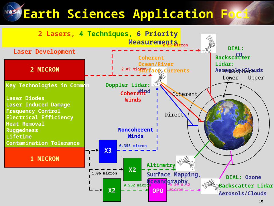
Key Priority Measurements for Earth Science Enterprise– Cloud/Aerosols and Radiative Forcing– Tropospheric Winds/River Flow– Tropospheric Ozone– Carbon Cycle (CO2, Biomass)– Surface Mapping– Oceanography
Earth Sciences Application Foci

Upendra Singh, LaRC 9
Backscatter Lidar• Cloud • Aerosol
Differential Absorption Lidar (DIAL)• Ozone• Carbon DioxideDoppler Lidar
• Wind Fields• River Flow
Altimetry Lidar• Ice Sheet Mass Balance • Vegetation Canopy• Land Topography
fDoppler
Frequency
TransmitPulse
Return
Velocity = (/2) fDoppler
TArrival
Time
TransmitPulse
Return
Range = (c/2)TArrival
TArrivalTime
TransmitPulse
Return
Density = IS/IT
Range = (c/2)Tarrival
IT
IS
off on
TransmitPulses
Returns
Concentration = log[ I(on)/ I(off)]
Wavelength
Lidar Techniques and Measurements
Upendra Singh, LaRC 10
PulsedLaser Development
Atmosphere:Lower Upper
DIAL: CO2
X3
OPO
DIAL: Ozone
2 Lasers, 4 Techniques, 6 Priority Measurements
0.30-0.32 micron
Backscatter Lidar: Aerosols/Clouds
X2Surface Mapping, Oceanography
X2
0.355 micron
Altimetry:
1.06 micron
2.05 micron
1 MICRON
Doppler Lidar: Wind
Backscatter Lidar:
Aerosols/Clouds
Coherent
Direct
0.532 micron
2 MICRON
Key Technologies in Common
Laser Diodes Laser Induced DamageFrequency ControlElectrical Efficiency Heat Removal Ruggedness LifetimeContamination Tolerance
Earth Sciences Application Foci
2.05 micron
Coherent Ocean/RiverSurface Currents
CoherentWinds
NoncoherentWinds

Upendra Singh, LaRC 1111
2 µ Test Bed
1 µ Test BedKnowledge
Laser Induced Damage
Now: 15 J/cm2 for 5 nsec
Goal: 60 J/cm2 for 5 nsec
Frequency Control
Now: < .25 pm
Goal: < .005 pm
Lifetime
Now: 850? M shots
Goal: 2 G shots
Heat Removal
Now: 110 Watts
Goal: 300 Watts
Contamination Tolerance
Now: 50, A/10
Goal: Better Tolerance
Electrical Efficiency
Now: 3-4%
Goal: 6%
Ruggedness
Now: 1 min @ 10G
Goal: 1 min @ 15 G
Laser Transmitter Testbeds

Upendra Singh, LaRC 12
Establishing Space-hardened Laser
Transmitter Test Beds (1µm laser at GSFC & 2µm at LaRC)
Development and Qualifications of Space-based Laser Diode Arrays ( 808nm diodes at GSFC & 792nm at LaRC)
Advancing Wavelength Conversion Technology for Space-based Lidars ( Low Energy/HRT at GSFC & High Energy/LRT at LaRC)

Upendra Singh, LaRC 13
• Deliverables
•Space-hardened 1- and 2-micron Laser Transmitters (Efficient, Conductively-cooled)
•Space-hardened Conductively Cooled Laser Diode Arrays
•Non-linear Optical Parametric and Harmonic Generation for Ozone, Chemical and Biological Species, and Water Vapor Detection
NASA Laser Risk Reduction Program
Funding ($M):
FY 03 FY 04 FY 05 FY 06 FY 07 FY 08
OAT 5 5 5 5 5 5
OES 4 4 4 4 4 4
Total 9 9 9 9 9 9
Upendra Singh, LaRC 14
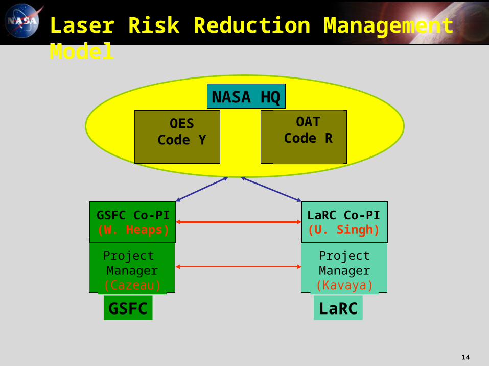
Laser Risk Reduction Management Model
ProjectManager(Kavaya)
LaRC
LaRC Co-PI(U. Singh)
GSFC
Project Manager(Cazeau)
GSFC Co-PI(W. Heaps)
NASA HQ
OESCode Y
OATCode R

Upendra Singh, LaRC 15
LRRP Description
• Pro-actively targets deficiencies in laser technology for focused development and risk mitigation– Technology readiness overestimated in past due to extrapolation
from prior heritage– Flight lasers are still at the “build-to-order” R&D stage
• Primary focus is on high-power (i.e., transmitter-class) lasers for space-based remote sensing applications– High-performance Nd:YAG systems (1 µm)– Emerging holmium- and thulium-doped lasant materials (2 µm)– Nonlinear generation schemes based on 1- and 2- µ m pump
sources• Harmonic generation• Optical parametric amplification/oscillation (OPA/OPO)
• Small investments in ancillary enhancing and enabling technologies which offer potential to reduce demand for laser power (detectors, innovative receiver approaches)

Upendra Singh, LaRC 16
• 2-micron laser transmitter– Demonstrate technologies leading to a conductively cooled, diode-pumped 2-micron
laser suitable for space-based lidar application– Address major laser development issues: High energy, high efficiency, laser-induced
optical and thermal damage, system thermal management• High-power diode laser pump arrays
– Develop, scale, and qualify long-lived, space-compatible laser diode arrays with current vendors
– Evaluate currently available laser diode arrays for performance, life and configuration required for future space-based laser missions
– Establish Characterization and Lifetime Test Facility to address laser diode issues:• Limited reliability and lifetime• Lack of statistical and analytical bases for performance and lifetime prediction
– Conceive advanced laser diode array architectures with improved efficiency and thermal characteristics
• Nonlinear optics research for space-based ozone DIAL– Spectrally narrow, tunable, robust UV laser architectures– Develop long-lived, efficient, space-compatible, nonlinear optical
materials/techniques• Receiver technologies
– Develop integrated heterodyne receiver to demonstrate 3-dB improvement of coherent lidar system efficiency with 80% reduction of required local oscillator power
– Develop improved quantum efficiency photon-counting detectors at 2 micron• Laser physics and advanced materials research
– Develop line tunable diode-pumped Nd laser system for pumping nonlinear UV generation schemes
– Develop narrowband, long pulse, low average power pump laser for wavelength control of lidar systems
LRRP Application Driven Elements

Upendra Singh, LaRC 17
NASA Laser Risk Reduction Program
2003 2007 Missions
Backscatter Lidar• Cloud • Aerosol
Differential Absorption Lidar (DIAL)
• Carbon Dioxide• Ozone
Doppler Lidar• Wind Fields• River Flow
Laser Altimeter• Ice Sheet Mass and
Topography • Vegetation Canopy• Land Topography• Ocean Mixed Layer
Depth• S/C-S/C Ranging
WavelengthConversion
1-Micron Laser
2-Micron Laser
Efficiency(Green=30%UV=20%)
SHG/THG
OPO/OPA
SpaceQualification
Heat Removal(All Conductive)
Contamination
OpticsDamage(2G/3 yr)
Lifetime(2G Shots)
PumpDiodes
Coupling
Packaging
FailureMechanisms
Availability(COTS)
LifetimeEffects
Performance
Beam Quality
LaserDesign
Efficiency(4% WPE)
Modeling
Laser Physics
Energy (1 J)/Power (10-100W)
Materials
Beam Quality/Spectrum
CompactHeritage derived from both Earth and Solar System apps.

Upendra Singh, LaRC 18
Lidar Technologies
Scanner
Receiver
AutoAlign
Pointing
Telescope
Detector
Y S
CO2 Profiling X
Global Winds X
Ozone Profiling X
Chem/Bio Sensing X
Landing/Rendezvous X
Water Vapor Profiling X
Laser Transmitter Technologies Measurements
XRanging/Altimetry X
Clouds/Aerosols X
Customers
Enabling Technology Elements
X
2-Micron LidarTransmitter
FrequencyController
Amplifier
IRWavelength
Converter
UVWavelengthConverter
1-Micron LidarTransmitter
X
X
X

Upendra Singh, LaRC 19
Laser Risk Reduction Program
A. Pump Laser Diodes Risk Reduction
– LaRC to advance diodes in 790 nm wavelength region
– Lifetime and characterization testing
– Radiation testing performed at GSFC
B. Conductively cooled laser
– 2-micron partially conductively-cooled laser is precursor to fully conductively-cooled space-capable design
C. Contamination
– GSFC Contamination protocols will be made available to support the contamination & lifetime study and tests at LaRC
D. Non-Linear Material & OPO Modeling
– LaRC to develop high peak power OPO’s
– Non-linear materials to be included in diode radiation test
E. Design and Packaging
– Packaging methodology for space flight-capable laser
A
E
D
C
B

Upendra Singh, LaRC 20
Laser Resonator
PowerEfficiency
LaserDiodes
AvailabilityLife/Quality
WavelengthConversion
PowerEfficiency
ReceiverSubsystem
EfficiencySize/Mass
Material Res & Quantum Mech.
Modeling
Laser Amplifier
Rad & DamageTests Multi-Joule
12Hz2-micron
Transmitter Laser
Define Reqmts& Innovations
TestPerf./Reliability
Test/Charact.Facility
Life TestQuality
CContamination
& Lifetime Study and Tests
Laser Oscillator
A Contamination& HandlingProtocols
QualificationProcedures
Global Winds& CO2
GlobalOzoneHighly-Efficient
Heterodyne Receiver
Define Reqmts& Innovations
Low-NoiseDetector for CO2 Meas.
CharacterizationFacilities
LightweightScanningTelescope
Dual PumpParametricOscillator
Lab DemoHigh Power
Conversion to UV
Normal ModeIntra-cavity
SHG Pump Laser
Efficient conversion to
UV
Damage/Rad/Life Tests Packaging
100mJ @ 100Hz 308nm & 320nm
2% efficiency
FY 02 FY 03 FY 04 FY 05 FY 06 FY 07
A Rad Th/Vac Tests
DNon-linear material & OPO modeling
BConductively-Cooled
Laser Head
EPackaging
(Flight-HardenedSystem)
A AdvanceLaser Diode
Technologies
Laser Risk Reduction ProgramLaRC Component

Upendra Singh, LaRC 21
Laser Resonator
Design
1.5J, 10Hz Fully conductively-cooled
2-micron laser
FY 02 FY 03 FY 04 FY 05 FY 06 FY 07
Partially conductively-cooled
laser head
Laser Risk Reduction Program2-micron technology roadmap
Partially conductively-cooled osc
Partially conductively-cooled amp
1.5J, 2HzPartially conductively-
cooled 2-micron laser
Fully conductively-cooled
laser head
Fully conductively-cooled osc
Fully conductively-cooled amp
DesignLessons
DesignLessons
Validation tool
DesignLessons
Space-capable design

Upendra Singh, LaRC 22
2-Micron Pulsed Transmitter Laser
Objective: Develop a high energy, high efficiency, conductively-cooled solid-state 2-micron laser for space lidar applications.
Application: Measurement of global CO2 and winds from LEO.
Accomplishments
• Successful demonstration of Ho,Tm:LuLF laser system with 1050 mJ Q-switched output energy. This was accomplished by one power oscillator and two amplifiers operating in double pulse mode. Single-pulse output is 0.6 J.
• Notional space-based wind profiling missions require pulse energies from 1 to 5 J, depending on the scenario
• Milestone achieved with 2-Hz PRF; >12 Hz desired for LEO
300
400
500
600
700
800
900
1000
1100
30 40 50 60 70 80
Output Pulse Energy (mJ)
2nd Amplifier Current (A)
115 mJ input pulse energy to 1st amplifier (single pulse)185 mJ input pulse energy to 1st amplifier (double pulse)630 mJ input pulse energy to 2nd amplifier (double pulse)
1 J

Upendra Singh, LaRC 23
0
1
2
3
4
5
6
7
8
0 1 2 3 4 5 6Dissipated Heat (W)
RelativeTemp Rise (
oC)
Cu/Beo Package
Rth = 1.88 oC/W
Diamond Package
Rth = 1.56 oC/W
Pump Laser Diode Advancement and Validation
Objective
Develop state-of-the-art characterization and life-time test facility and address 792-nm laser diode issues:
• Limited reliability and lifetime• Lack of statistical and analytical bases for performance and lifetime prediction• Limited commercial availability
Develop advanced laser diode array (LDA) architectures with improved efficiency and thermal characteristics
Accomplishments
Fabricated and tested an advanced LDA package utilizing diamond substrate and heatsink. Demonstrated 17% reduction in thermal resistance relative to the standardBeO/Cu package that can translate to increased lifetime and reliability.
Thermal Image of Diamond LDA
Diamond Package cools 36% faster

Upendra Singh, LaRC 24
• Reached 150 mJ (record) of UV at 320 nm with 10% (record) 1µm-UV efficiency; reached 115 mJ at 308 nm
• Developed innovative UV generation architectures
• Critical to trop ozone profile measurement from space
LRRP Recent Accomplishments

Upendra Singh, LaRC 25
• Current partnerships and collaborations
Laser Risk Reduction Program- Collaborations
• Industry
• University
• Government
NASA Laser/Lidar Risk Reduction ProgramLaRCGSFC
JPL•Tunable LO Laser
•Integrated Receiver
DOE•UV Laser
DOD•Laser Diodes, •EO Scanner
Coherent, CEO,•Laser Diodes
ITT•UV Laser
Sci. Material•Laser Crystals
Swales, UMD•Cond. Cool. Pkg.
Boston College•Quan. Mech. Model.
VLOC, CVI•Optics
•CoatingsNorthrop Gruman
•Solid State Lasers
Schafer,Plasma Processes
•Lightweight Telescopes
JHU, APL•Non Linear Op
Upendra Singh, LaRC 26
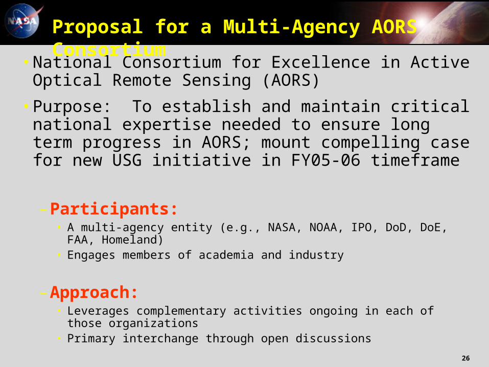
•National Consortium for Excellence in Active Optical Remote Sensing (AORS)
•Purpose: To establish and maintain critical national expertise needed to ensure long term progress in AORS; mount compelling case for new USG initiative in FY05-06 timeframe
– Participants:• A multi-agency entity (e.g., NASA, NOAA, IPO, DoD, DoE, FAA,
Homeland)• Engages members of academia and industry
– Approach:• Leverages complementary activities ongoing in each of those
organizations• Primary interchange through open discussions
Proposal for a Multi-Agency AORS Consortium

Upendra Singh, LaRC 27
Chem-Bio Det
Aerosols
Wind
Aviation Safety
Multi-Agency Active Optical
Remote Sensing
Consortium
Industry
Home- land
NASA
NOAA
IPO
DoE
DoD
Academia
Clouds/Aerosols
Wind
Trop. Chemistry
Carbon dioxide
Biomass
Water Vapor
Land/Ice Topography
Wake Vortices
Ocean Mixed Layer
Solar System Science
Wind
Water Vapor
CO2
Aerosols
Wind
Aerosols
Chem-Bio Detection
Target Recognition
Tactical Imaging
Water Vapor
Chem- Bio Detection
Clouds and Aerosols
Wind
Humidity
Aerosols
FAA
Chem-Bio Detection
Aviation Safety
Wake Vortices
Turbulence
Wind Shear
Proposed Consortium Partners and Measurement NeedsNSF
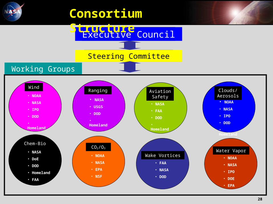
Upendra Singh, LaRC 28
Executive Council
Steering Committee
Wind
• NOAA
• NASA
• IPO
• DOD
• Homeland
Chem-Bio
• NASA
• DoE
• DOD
• Homeland
• FAA
CO2/O3
• NOAA
• NASA
• EPA
• NSF
Wake Vortices
• FAA
• NASA
• DOD
Water Vapor
• NOAA
• NASA
• IPO
• DOE
• EPA
Clouds/ Aerosols• NOAA
• NASA
• IPO
• DOD
• Homeland
Aviation Safety
• NASA
• FAA
• DOD
• Homeland
Ranging
• NASA
• USGS
• DOD
• Homeland
Working Groups
Consortium Structure

Upendra Singh, LaRC 29
DETECTOR
RECEIVER
TELESCOPE
SCANNER
Auto-AlignmentPOINTING
AORSSystem DemonstrationPackaging & Hardening
Flight Validation
Advanced AORS Technology Elements
UV Visible Near-IR Infrared 2-D
Heterodyne Direct Etalon
Meter-Class Deployable
Rotating Telescope HOE/DOE Liquid Crystal Solid State E-O
LASER
1 micron Laser Testbed
2 micron Laser Testbed
Wavelength Conversion
Laser Diode Pump
Space Hardening
Packaging
Sensors E-O Steerer Wavefront Corrector
Embeded Star Tracker Integrated INS

Upendra Singh, LaRC 30
Summary
• Developing AORS technology supports NASA’s Vision and Mission and enables a key “building block”
• A focused technology effort will enable the promise of AORS by closing critical remaining gaps in capability
• AORS will address key high resolution measurement needs within Codes Y and S and support other national needs

Upendra Singh, LaRC 31
Backup Charts

Upendra Singh, LaRC 32
Technology Roadmap: 2-micron & UV Sources
Laser Resonator
PowerEfficiency
LaserDiodes
AvailabilityLife/Quality
WavelengthConversion
PowerEfficiency
ReceiverSubsystem
EfficiencySize/Mass
Material Res & Quantum Mech.
Modeling
Laser Amplifier
Rad & DamageTests Multi-Joule
12 Hz2-Micron
Transmitter Laser
Define Reqmts.& Innovations
TestPerf./Reliability
Test/Charact.Facility
Life TestQuality
Contamination& Lifetime
Study and Tests
Laser Oscillator
Contamination& HandlingProtocols
QualificationProcedures
Global Winds& CO2
GlobalOzoneMeas.
Highly-EfficientHeterodyne
Receiver
Define Reqmts
& Innovations
Low-NoiseDetector for CO2 Meas.
Characterization
Facilities LightweightScanningTelescope
Dual PumpParametricOscillator
Lab DemoHigh Power
Conversion to UV
Normal ModeIntra-cavitySHG Pump
Laser
Efficient, High EConver to UV
Damage/Rad/Life Tests
Packaging500 mJ X 10 Hz 308nm &320 nm
2% Efficiency
Rad Th/Vac Tests
Non-linear Material
Res. & OPO Modeling
Conductively-Cooled
Laser Head
Packaging (Flight-Hardened
System)
AdvanceLaser Diode
Technologies

Upendra Singh, LaRC 33
• Developed diode laser characterization facility• Diagnostics to understand failure modes of solid state lasers
• Enables active wind & CO2 measurement from space
Power and Polarization
Pulse Width
Wavelength and Linewidth
Beam Profile and Divergence
Optical Spectrum Analyzer
Power Meter
Integrating Sphere
Laser Diode
ThermalInterface
LD Characterization LD Lifetime Test
Current, Voltage, Temp, and PRF
Near FieldEmitters Image
Laser DiodeThermalProfile
Power and Polarization
Pulse Width
Wavelength and Linewidth
Beam Profile and Divergence
Optical Spectrum Analyzer
Power Meter
Integrating Sphere
Laser Diode
ThermalInterface
LD Characterization LD Lifetime Test
Current, Voltage, Temp, and PRF
Near FieldEmitters Image
Laser DiodeThermalProfile
LRRP Recent Accomplishments

Upendra Singh, LaRC 34
0
1
2
3
4
5
6
7
8
0 1 2 3 4 5 6Dissipated Heat (W)
RelativeTemp Rise (
oC)
Cu/Beo Package
Rth = 1.88 oC/W
Diamond Package
Rth = 1.56 oC/W
792 nm Diamond Package LDA
Diamond Package dissipates excess heat more efficiently than standard BeO/Cu package resulting in increased lifetime.
Thermal resistance of diamond package is 17% lower than BeO/Cu package
Pulsewidth 0.1 – 1.0 msec Current 80 ARep Rate 10 HzOp Temp 15oC
LRRP Recent Accomplishments

Upendra Singh, LaRC 35
0.0
0.5
1.0
1.5
41.00 41.50 42.00 42.50 43.00 43.50 44.00 44.50 45.00
Time (sec)
Relative Temperature (
oC)
1.43 sec
0.92 sec
Diamond Package
BeO/Cu Package
Diamond Package cools 36% faster
Thermal Characteristics of Diamond LDA
• Enables all lidar measurements