updated notes from the june 22 conf. call on weld details, bushing details, and c-c bolts
TRANSCRIPT
UPDATED Notes from the June 22 Conf. Call on Weld Details, Bushing Details, and C-C Bolts

Call agenda:• The first two bullets will focus on the results of discussions at MEL
with John Edwards and Fred Simmonds who are visiting from PPPL.
• Weld access, weld locations & length, and weld shims & details. (Fred, Kevin and others)
• Bushing design. (fabrication methods, tolerances, installation methods) (John, Paul, and others)
• C-C additional bolts (Mike and Gary: please show your side showing accessibility of the new bolts and a drawing showing locations).
• Outer shim designs & spec. (Mike, Geoff & Gary) shim details; retention during assembly; sealing of gaps to retain VV insulation; surface roughness specified for Alumina, etc.)
• Conclusions & action items on all of the above.

Notes on Weld Details• The casting flanges will need to be chamfered to give
proper access for the TIG gun. – CAUTION: need to make sure that chamfering will
leave enough flange for welding in tight areas. – Chamfers can be hand-ground. – Weld is ½” x ½” – chamfer is still needed. (need BN
concurrence). • Peening looks ok. • A-B flange in the “concave” region: Stress is ~15 ksi
in some of these regions. More detailed stress analysis is needed to see if this double chamfer weld is really needed.
• Will try on water jet cut flanges next week. • MV will check details with Bob Keilbach.• YES - Can we open up the gaps between the shims
to ¼” to permit more “wiggle room” for the shims and avoid build-up of tolerances? (this is also an issue for the outboard shims – see slide 6)
– Can weld SS strips over the gaps to seal insulation or inject Great Stuff or both. DO THIS WELD ON INBOARD SIDEINSTALL FIBERGLASS PLUG AT BASE THEN INJECT GREAT STUFF.
PPPL needs to sketch what is planned for weld test.

Stress Intensity of Weld and shim (units are Psi)
Note that most of the weld is yellow: ie, ~13 ksi.
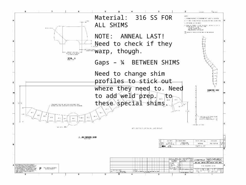
Material: 316 SS FOR ALL SHIMS
NOTE: ANNEAL LAST! Need to check if they warp, though.
Gaps – ¼” BETWEEN SHIMS
Need to change shim profiles to stick out where they need to. Need to add weld prep. to these special shims.

Fillet welds 2 are already tough and there is little room to grow
Obviously, we could chamfer and produce a weld as a combo of a reseeded weld and the fillet near the edges and the transition zones but that would be VERY hard to model and transfer to FEA as I would need blending, curves, etc.
Extended shim
But stress there is moderate – 9-13 ksi, so this weld size should be ok
BUT can’t we model the fillet as a fillet to get accurate stress prediction ??

Bushings• John Edwards - Making the bushing is not the time consuming part
– it’s getting to there.• There is a lot of putting things together and taking things apart.
– In locations where studs are pre-fit, the coils would have to be taken apart again. Maybe 4 locations. FIX: don’t use tight fitting bushings there.
– Can’t get Supernuts out in some areas.– The casting moves around until it’s locked down. Installing the bushings
one at a time is the time consuming part. – Need to tighten the castings down, take a subset of nuts out, measure,
install bushings.• Option A: get bushings with “standard” ID hole fitted to the stud and
then machine the OD to fit.• Option B: use filled epoxy to tightly fit the bushings in place. • Need to get time and cost down for the bushings. • Are the spherical washers retained?

“Super Bolt” Nut
7/16” Washer(Inconel 718)
½” Load Washer(Titanium)
.030” G-11 Insulator
G-11 Bushing
½” Nominal Shim (316-SST) with Alumina Coating
1.375” dia. Stud (316-SST)
Modular Coil
Modular Coil
ISSUE: electrical short potential on OD of load washers!
FIX: Machine washer OD’s to provide 0.032” clearance IF NEEDED; paint OD with epoxy at assembly.
• MV: Machine the bushings to lightly press fit.
•A lathe will be moved into the assembly area.
• Studs have tolerances on the shank of +/- 0.001”.
•Bushing will be made of rolled G10CR with ID sized for a sliding fit. (nom. Clearance of 0.001”).
•Install bushings in groups of 2-4, spaced around.
We have a bushing deal! MV will prototype.

OLD drawing – Spherical washers are out!! Brad will get us R2 of this drawing.

C-C• Best way to establish access
feasibility is to put a B-C together and then try to mock up reaching into these areas.
• May require development of semi-remote handling tooling, but we can do it.
– Iter? Phil Spampanato? • The “hardest to access” 3 are the
important ones – if we get these in, the 3 above really could be deleted.
• This area might require special bushings – fit up before the TF coils & use a special tool to install at final assembly.
• ORNL may make a wooden or stereo lithography mock-up. Use for top and bottom access studies.
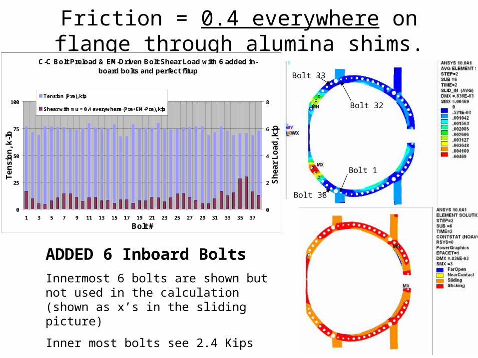
Friction = 0.4 everywhere on flange through alumina shims.
ADDED 6 Inboard Bolts
Innermost 6 bolts are shown but not used in the calculation (shown as x’s in the sliding picture)
Inner most bolts see 2.4 Kips
Sliding is 4.7 mils
Bolt 1
Bolt 32
Bolt 33
Bolt 38
XX
X
XX
X
C-C Bolt Preload & EM-Driven Bolt Shear Load with 6 added in-board bolts and perfect fitup
0
25
50
75
100
1 3 5 7 9 11 13 15 17 19 21 23 25 27 29 31 33 35 37
Bolt #
Te
ns
ion
, k-l
b
0
2
4
6
8
Sh
ea
r L
oa
d, k
ip
Tension (Pre), kip
Shear with mu = 0.4 everywhere (Pre+EM-Pre), kip
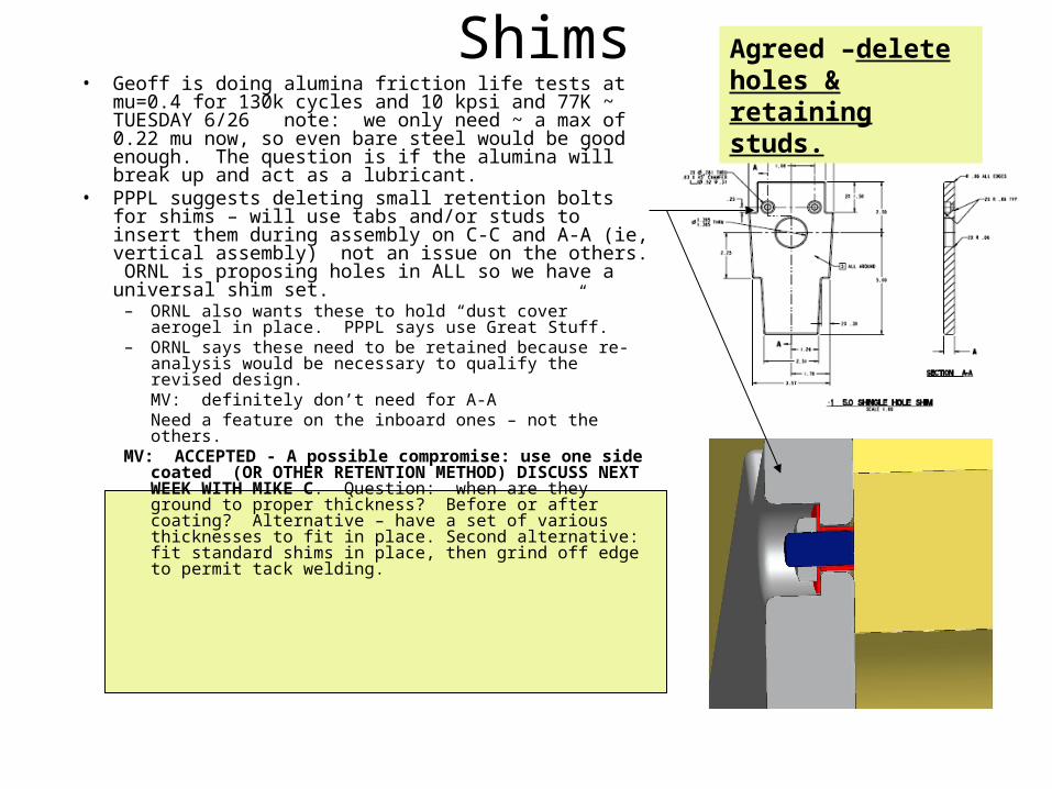
Shims• Geoff is doing alumina friction life tests at mu=0.4 for
130k cycles and 10 kpsi and 77K ~ TUESDAY 6/26 note: we only need ~ a max of 0.22 mu now, so even bare steel would be good enough. The question is if the alumina will break up and act as a lubricant.
• PPPL suggests deleting small retention bolts for shims – will use tabs and/or studs to insert them during assembly on C-C and A-A (ie, vertical assembly) not an issue on the others. ORNL is proposing holes in ALL so we have a universal shim set.
– ORNL also wants these to hold “dust cover” aerogel in place. PPPL says use Great Stuff.
– ORNL says these need to be retained because re-analysis would be necessary to qualify the revised design.MV: definitely don’t need for A-ANeed a feature on the inboard ones – not the others.
MV: ACCEPTED - A possible compromise: use one side coated (OR OTHER RETENTION METHOD) DISCUSS NEXT WEEK WITH MIKE C. Question: when are they ground to proper thickness? Before or after coating? Alternative – have a set of various thicknesses to fit in place. Second alternative: fit standard shims in place, then grind off edge to permit tack welding.
Agreed –delete holes & retaining studs.

Shims (cont’d.)• Shim trimming tests being
performed at PPPL tomorrow. • Gaps between shims – WILL BE
¼” AND FILLED WITH AEROGEL (WITH FIBERGLAS BOTTOM PLUG).
• Next week when PPPL performs weld tests on the water jet flange, we’ll also perform Great Stuff sealing tests and do LN2 dunk tests to demonstrate adhesion to SS.
• USE RELAXED TOLERANCES ON PROFILE!!!
GROOVES SHOWN REPRESENT THE 2 CUT LENGTHS REQUIRED FOR ALL COIL INSTALLATIONS
“CUT OFF” TAB AND UNIVERSAL SHIM DESIGN ACCEPTED. GEOFF WILL WORK GROOVE DETAILS WITH A&A AND GET BACK TO MIKE C. GROOVE WILL BE ACROSS TOP AND BOTTOM SURFACES ONLY (IE, NO SIDE NOTCHES AS SHOWN ABOVE)
KEVIN WILL USE THIS SHIM TYPE FOR HIS TESTS
Make id 1.470-1.490
Make non-stepped side profiles.
Break all edges 0.032-0.045 cheaply.
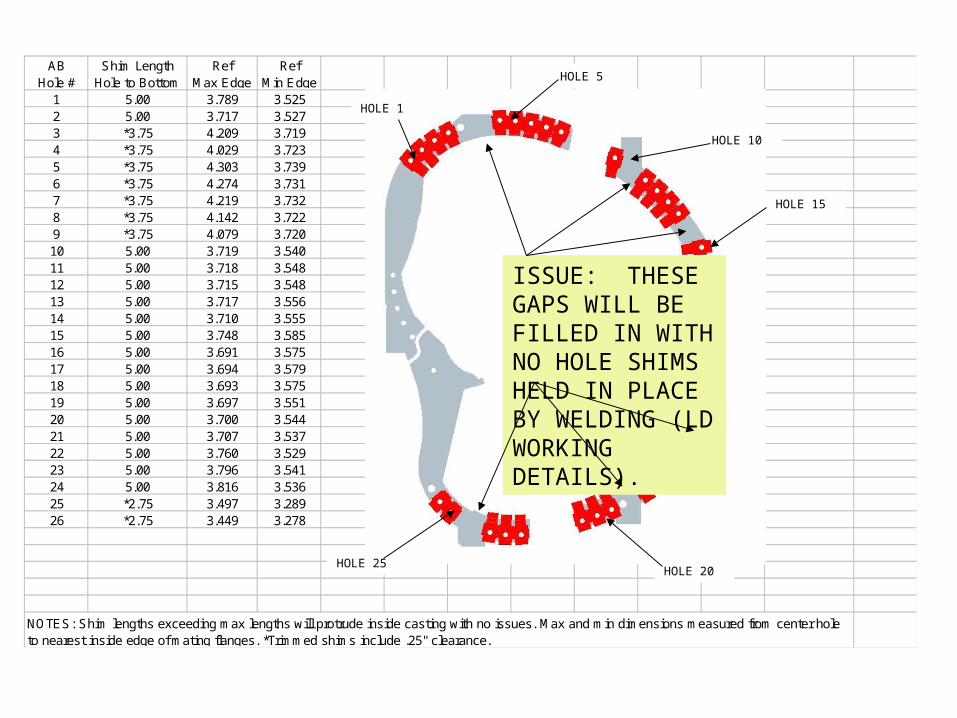
AB Hole #
Shim Length Hole to Bottom
Ref Max Edge
Ref Min Edge
1 5.00 3.789 3.5252 5.00 3.717 3.5273 *3.75 4.209 3.7194 *3.75 4.029 3.7235 *3.75 4.303 3.7396 *3.75 4.274 3.7317 *3.75 4.219 3.7328 *3.75 4.142 3.7229 *3.75 4.079 3.72010 5.00 3.719 3.54011 5.00 3.718 3.54812 5.00 3.715 3.54813 5.00 3.717 3.55614 5.00 3.710 3.55515 5.00 3.748 3.58516 5.00 3.691 3.57517 5.00 3.694 3.57918 5.00 3.693 3.57519 5.00 3.697 3.55120 5.00 3.700 3.54421 5.00 3.707 3.53722 5.00 3.760 3.52923 5.00 3.796 3.54124 5.00 3.816 3.53625 *2.75 3.497 3.28926 *2.75 3.449 3.278
NOTES: Shim lengths exceeding max lengths will protrude inside casting with no issues. Max and min dimensions measured from center hole to nearest inside edge of mating flanges. *Trimmed shims include .25" clearance.
HOLE 1
HOLE 5
HOLE 10
HOLE 15
HOLE 20HOLE 25
ISSUE: THESE GAPS WILL BE FILLED IN WITH NO HOLE SHIMS HELD IN PLACE BY WELDING (LD WORKING DETAILS).