update instructions - medsensor.rumedsensor.ru/files/ge/us/logiq_500_sm.pdf · update instructions...
TRANSCRIPT
ULTRASOUND PROGRAM MANAGEMENT GROUP
UPDATE INSTRUCTIONS
Date : August 28, 2000
To : Holders of P9030TA LOGIQ 500 Service Manual
Subject : P9030TA LOGIQ 500 SERVICE MANUAL UPGRADE – REV 14
Enclosed please find the following Rev14 upgrade pages.
SUMMARY OF CHANGES (Reason)
• Chapter 1: Addition of the caution label and change of address• Chapter 3: Additional information for Ver. 6 system and the new probes• Chapter 4: Additional information for Ver. 6 system software options• Chapter 5: Additional information for Ver. 6 system• Chapter 6: Additional descriptions for new FRUs and others
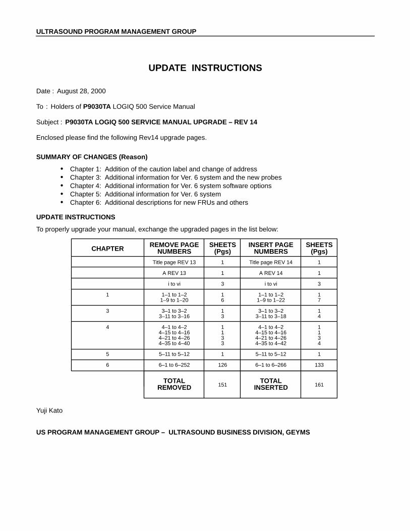
UPDATE INSTRUCTIONS
To properly upgrade your manual, exchange the upgraded pages in the list below:
Title page REV 13 1 Title page REV 14 1
A REV 13 1 A REV 14 1
i to vi 3 i to vi 3
1 1–1 to 1–2 1 1–1 to 1–2 11–9 to 1–20 6 1–9 to 1–22 7
3 3–1 to 3–2 1 3–1 to 3–2 13–11 to 3–16 3 3–11 to 3–18 4
4 4–1 to 4–2 1 4–1 to 4–2 14–15 to 4–16 1 4–15 to 4–16 14–21 to 4–26 3 4–21 to 4–26 34–35 to 4–40 3 4–35 to 4–42 4
5 5–11 to 5–12 1 5–11 to 5–12 1
6 6–1 to 6–252 126 6–1 to 6–266 133
REMOVE PAGE SHEETS INSERT PAGE SHEETSNUMBERS (Pgs) NUMBERS (Pgs)CHAPTER
TOTAL TOTALREMOVED INSERTED151 161
Yuji Kato
US PROGRAM MANAGEMENT GROUP – ULTRASOUND BUSINESS DIVISION, GEYMS

P9030TARevision 14
LOGIQ 500
Service Manual
Copyright 1994, 1995, 1996, 1997, 1998, 1999, 2000 by General Electric Company

LOGIQ 500 SERVICE MANUALGE MEDICAL SYSTEMSP9030TA
A
REV 14
LIST OF EFFECTIVE PAGES
REV DATE PRIMARY REASON FOR CHANGE
0 March 10, 1994 Initial release1 July 25, 1994 Software version 1.10 Release, Error correction and Additional descriptions2 August 15, 1994 Error Correction3 October 26, 1994 Software version 1.11 Release, Error correction and Additional descriptions4 January 25, 1995 Software version 1.20 Release, Error correction and Additional descriptions5 May 8, 1995 Software version 2.00 Release, Error correction and Additional descriptions6 November 17, 1995 Software version 2.20 Release7 July 10, 1996 Software version 3.00 Release8 March 10, 1997 Software version 3.10 Release9 October 23, 1997 Software version 4.00 Release10 June 19, 1998 Software version 4.10 Release11 April 21, 1999 Software version 4.20 Release12 August 30, 1999 Software version 5.00 Release13 December 14, 1999 Software version 5.00A Release14 August 28, 2000 Software version 6.00 Release
PAGE REV PAGE REV PAGE REV PAGE REV PAGE REV
Title page 14. . . . . . . . . GE Logo page –. . . . . . P9030CB 2. . . . . . . . . . . P9030CC 4. . . . . . . . . . P9030CD 0. . . . . . . . . . A 14. . . . . . . . . . . . . . . . . i to vi 14. . . . . . . . . . . . .
Chapter 11–1 14. . . . . . . . . . . . . . . 1–2 0. . . . . . . . . . . . . . . . 1–3 4. . . . . . . . . . . . . . . . 1–4 12. . . . . . . . . . . . . . . 1–5 to 1–7 13. . . . . . . . . 1–8 to 1–9 12. . . . . . . . . 1–10 to 1–22 14. . . . . .
Chapter 22–1 10. . . . . . . . . . . . . . .
2–2 0. . . . . . . . . . . . . . . . 2–3 4. . . . . . . . . . . . . . . . 2–4 12. . . . . . . . . . . . . . . 2–5 9. . . . . . . . . . . . . . . . 2–6 0. . . . . . . . . . . . . . . . 2–7 12. . . . . . . . . . . . . . . 2–8 5. . . . . . . . . . . . . . . . 2–9 to 2–10 0. . . . . . . . . 2–11 to 2–14 7. . . . . . . .
Chapter 33–1 14. . . . . . . . . . . . . . . 3–2 0. . . . . . . . . . . . . . . . 3–3 to 3–11 12. . . . . . . . 3–12 to 3–18 14. . . . . .
Chapter 44–1 14. . . . . . . . . . . . . . .
4–2 to 4–4 0. . . . . . . . . . 4–5 5. . . . . . . . . . . . . . . . 4–6 to 4–10 0. . . . . . . . . 4–11 8. . . . . . . . . . . . . . . 4–12 to 4–14 0. . . . . . . 4–15 to 4–16 14. . . . . . 4–17 10. . . . . . . . . . . . . . 4–18 7. . . . . . . . . . . . . . . 4–19 to 4–21 10. . . . . . 4–22 14. . . . . . . . . . . . . . 4–23 10. . . . . . . . . . . . . . 4–24 14. . . . . . . . . . . . . . 4–25 11. . . . . . . . . . . . . . 4–26 14. . . . . . . . . . . . . . 4–27 12. . . . . . . . . . . . . . 4–28 to 4–29 11. . . . . . 4–30 12. . . . . . . . . . . . . . 4–31 to 4–34 11. . . . . .
4–35 to 4–42 14. . . . . .
Chapter 55–1 5. . . . . . . . . . . . . . . . 5–2 to 5–3 0. . . . . . . . . . 5–4 7. . . . . . . . . . . . . . . . 5–5 to 5–7 12. . . . . . . . . 5–8 9. . . . . . . . . . . . . . . . 5–9 7. . . . . . . . . . . . . . . . 5–10 12. . . . . . . . . . . . . . 5–11 14. . . . . . . . . . . . . .
Chapter 66–1 to 6–3 14. . . . . . . . . 6–4 13. . . . . . . . . . . . . . . 6–5 to 6–10 10. . . . . . . . 6–11 to 6–14 11. . . . . . . 6–15 12. . . . . . . . . . . . . . 6–16 14. . . . . . . . . . . . . .
6–17 13. . . . . . . . . . . . . . 6–18 11. . . . . . . . . . . . . . 6–19 to 6–21 14. . . . . . 6–22 11. . . . . . . . . . . . . . 6–23 14. . . . . . . . . . . . . . 6–24 11. . . . . . . . . . . . . . 6–25 to 6–26 14. . . . . . 6–27 to 6–28 11. . . . . . 6–29 to 6–266 14. . . . .
Chapter 77–1 10. . . . . . . . . . . . . . . 7–2 4. . . . . . . . . . . . . . . . 7–3 to 7–6 9. . . . . . . . . . 7–7 to 7–20 10. . . . . . . .
Chapter 88–1 to 8–3 1. . . . . . . . . . 8–4 10. . . . . . . . . . . . . . .

LOGIQ 500 SERVICE MANUALGE MEDICAL SYSTEMS
P9030TA
TABLE OF CONTENTSi
REV 14
TABLE OF CONTENTS
SECTION TITLE PAGE
TABLE OF CONTENTS i. . . . . . . . . . . . . . . . . . . . . . . . . . . . . . . . . . . . . . . . . . . . . . . . . . . . . . . . . . . . . . . . . .
CHAPTER 1 – INTRODUCTION
1–1 SERVICE MANUAL CONTENTS 1–3. . . . . . . . . . . . . . . . . . . . . . . . . . . . . . . . . . . . . . . . . . . . . . . . . . . . . . .
1–2 SAFETY 1–4. . . . . . . . . . . . . . . . . . . . . . . . . . . . . . . . . . . . . . . . . . . . . . . . . . . . . . . . . . . . . . . . . . . . . . . . . . . . . 1–2–1 Warnings 1–4. . . . . . . . . . . . . . . . . . . . . . . . . . . . . . . . . . . . . . . . . . . . . . . . . . . . . . . . . . . . . . . . . . . 1–2–2 Specifications 1–18. . . . . . . . . . . . . . . . . . . . . . . . . . . . . . . . . . . . . . . . . . . . . . . . . . . . . . . . . . . . . .
1–3 EMC (Electromagnetic Compatibility) 1–19. . . . . . . . . . . . . . . . . . . . . . . . . . . . . . . . . . . . . . . . . . . . . . . . . . . 1–3–1 EMC Performance 1–19. . . . . . . . . . . . . . . . . . . . . . . . . . . . . . . . . . . . . . . . . . . . . . . . . . . . . . . . . . 1–3–2 Notice upon Installation of Product 1–19. . . . . . . . . . . . . . . . . . . . . . . . . . . . . . . . . . . . . . . . . . . . 1–3–3 General Notice 1–20. . . . . . . . . . . . . . . . . . . . . . . . . . . . . . . . . . . . . . . . . . . . . . . . . . . . . . . . . . . . . 1–3–4 Countermeasures against EMC–related Issues 1–20. . . . . . . . . . . . . . . . . . . . . . . . . . . . . . . . . 1–3–5 Notice on Service 1–20. . . . . . . . . . . . . . . . . . . . . . . . . . . . . . . . . . . . . . . . . . . . . . . . . . . . . . . . . . .
1–4 ADDRESS 1–21. . . . . . . . . . . . . . . . . . . . . . . . . . . . . . . . . . . . . . . . . . . . . . . . . . . . . . . . . . . . . . . . . . . . . . . . . .
CHAPTER 2 – INSTALLATION
2–1 PREINSTALLATION 2–3. . . . . . . . . . . . . . . . . . . . . . . . . . . . . . . . . . . . . . . . . . . . . . . . . . . . . . . . . . . . . . . . . . 2–1–1 Introduction 2–3. . . . . . . . . . . . . . . . . . . . . . . . . . . . . . . . . . . . . . . . . . . . . . . . . . . . . . . . . . . . . . . . . 2–1–2 Power Line Requirements 2–3. . . . . . . . . . . . . . . . . . . . . . . . . . . . . . . . . . . . . . . . . . . . . . . . . . . . . 2–1–3 Physical Specifications 2–4. . . . . . . . . . . . . . . . . . . . . . . . . . . . . . . . . . . . . . . . . . . . . . . . . . . . . . . 2–1–4 Recommended Ultrasound Room Layout 2–5. . . . . . . . . . . . . . . . . . . . . . . . . . . . . . . . . . . . . . .
2–2 INSTALLATION 2–8. . . . . . . . . . . . . . . . . . . . . . . . . . . . . . . . . . . . . . . . . . . . . . . . . . . . . . . . . . . . . . . . . . . . . . . 2–2–1 Introduction 2–8. . . . . . . . . . . . . . . . . . . . . . . . . . . . . . . . . . . . . . . . . . . . . . . . . . . . . . . . . . . . . . . . . 2–2–2 Average Installation Time 2–8. . . . . . . . . . . . . . . . . . . . . . . . . . . . . . . . . . . . . . . . . . . . . . . . . . . . . 2–2–3 Installation Warnings 2–8. . . . . . . . . . . . . . . . . . . . . . . . . . . . . . . . . . . . . . . . . . . . . . . . . . . . . . . . . 2–2–4 Checking the Components 2–8. . . . . . . . . . . . . . . . . . . . . . . . . . . . . . . . . . . . . . . . . . . . . . . . . . . . 2–2–5 Unpacking LOGIQ 500 2–9. . . . . . . . . . . . . . . . . . . . . . . . . . . . . . . . . . . . . . . . . . . . . . . . . . . . . . . . 2–2–6 MTZ Probe Holder Installation 2–11. . . . . . . . . . . . . . . . . . . . . . . . . . . . . . . . . . . . . . . . . . . . . . . . 2–2–7 Transducer Connection 2–12. . . . . . . . . . . . . . . . . . . . . . . . . . . . . . . . . . . . . . . . . . . . . . . . . . . . . . 2–2–8 Moving into Position 2–13. . . . . . . . . . . . . . . . . . . . . . . . . . . . . . . . . . . . . . . . . . . . . . . . . . . . . . . . . 2–2–9 Adjusting System Clock 2–13. . . . . . . . . . . . . . . . . . . . . . . . . . . . . . . . . . . . . . . . . . . . . . . . . . . . . . 2–2–10 Product Locator Installation Card 2–14. . . . . . . . . . . . . . . . . . . . . . . . . . . . . . . . . . . . . . . . . . . . . .

LOGIQ 500 SERVICE MANUALGE MEDICAL SYSTEMS
P9030TA
TABLE OF CONTENTSii
REV 14
SECTION TITLE PAGE
CHAPTER 3 – SYSTEM CONFIGURATION
3–1 INTRODUCTION 3–3. . . . . . . . . . . . . . . . . . . . . . . . . . . . . . . . . . . . . . . . . . . . . . . . . . . . . . . . . . . . . . . . . . . . .
3–2 DIMENSIONS 3–3. . . . . . . . . . . . . . . . . . . . . . . . . . . . . . . . . . . . . . . . . . . . . . . . . . . . . . . . . . . . . . . . . . . . . . . .
3–3 ELECTRICAL SPECIFICATIONS 3–5. . . . . . . . . . . . . . . . . . . . . . . . . . . . . . . . . . . . . . . . . . . . . . . . . . . . . . . 3–3–1 Power Supply 3–5. . . . . . . . . . . . . . . . . . . . . . . . . . . . . . . . . . . . . . . . . . . . . . . . . . . . . . . . . . . . . . . 3–3–2 Facility Power Receptacle 3–5. . . . . . . . . . . . . . . . . . . . . . . . . . . . . . . . . . . . . . . . . . . . . . . . . . . . .
3–4 STORAGE AND OPERATION REQUIREMENTS 3–5. . . . . . . . . . . . . . . . . . . . . . . . . . . . . . . . . . . . . . . . .
3–5 OPTIONAL PERIPHERALS 3–6. . . . . . . . . . . . . . . . . . . . . . . . . . . . . . . . . . . . . . . . . . . . . . . . . . . . . . . . . . . . 3–5–1 Peripherals/Accessories Connector Panel 3–6. . . . . . . . . . . . . . . . . . . . . . . . . . . . . . . . . . . . . . . 3–5–2 List of Optional Peripherals 3–11. . . . . . . . . . . . . . . . . . . . . . . . . . . . . . . . . . . . . . . . . . . . . . . . . . . 3–5–3 Power Consumption of Optional Peripherals 3–17. . . . . . . . . . . . . . . . . . . . . . . . . . . . . . . . . . . .
3–6 VIDEO SPECIFICATIONS 3–18. . . . . . . . . . . . . . . . . . . . . . . . . . . . . . . . . . . . . . . . . . . . . . . . . . . . . . . . . . . .
CHAPTER 4 – FUNCTIONAL CHECKS
4–1 INTRODUCTION 4–3. . . . . . . . . . . . . . . . . . . . . . . . . . . . . . . . . . . . . . . . . . . . . . . . . . . . . . . . . . . . . . . . . . . . . 4–1–1 Required Equipment 4–3. . . . . . . . . . . . . . . . . . . . . . . . . . . . . . . . . . . . . . . . . . . . . . . . . . . . . . . . . .
4–2 FUNCTIONAL CHECK PROCEDURES 4–3. . . . . . . . . . . . . . . . . . . . . . . . . . . . . . . . . . . . . . . . . . . . . . . . . 4–2–1 Basic Controls 4–4. . . . . . . . . . . . . . . . . . . . . . . . . . . . . . . . . . . . . . . . . . . . . . . . . . . . . . . . . . . . . . .
4–3 DIAGNOSTICS 4–9. . . . . . . . . . . . . . . . . . . . . . . . . . . . . . . . . . . . . . . . . . . . . . . . . . . . . . . . . . . . . . . . . . . . . . . 4–3–1 Service Software Menu 4–9. . . . . . . . . . . . . . . . . . . . . . . . . . . . . . . . . . . . . . . . . . . . . . . . . . . . . . . 4–3–2 Diagnosis Test Menu 4–10. . . . . . . . . . . . . . . . . . . . . . . . . . . . . . . . . . . . . . . . . . . . . . . . . . . . . . . . 4–3–3 Utility Menu 4–15. . . . . . . . . . . . . . . . . . . . . . . . . . . . . . . . . . . . . . . . . . . . . . . . . . . . . . . . . . . . . . . .
(A) TIME ADJUSTMENT 4–16. . . . . . . . . . . . . . . . . . . . . . . . . . . . . . . . . . . . . . . . . . . . . . . . . . . (B) ERROR LOG DISPLAY 4–17. . . . . . . . . . . . . . . . . . . . . . . . . . . . . . . . . . . . . . . . . . . . . . . . . (C) TROUBLE IMAGE SAVE/LOAD/DISPLAY 4–18. . . . . . . . . . . . . . . . . . . . . . . . . . . . . . . . . (D) USER DATA BACKUP 4–21. . . . . . . . . . . . . . . . . . . . . . . . . . . . . . . . . . . . . . . . . . . . . . . . . . (E) USER OPTION DISPLAY 4–24. . . . . . . . . . . . . . . . . . . . . . . . . . . . . . . . . . . . . . . . . . . . . . . (F) BOARD CONFIGURATION DISPLAY 4–26. . . . . . . . . . . . . . . . . . . . . . . . . . . . . . . . . . . . . (G) SOFTWARE CONFIGURATION DISPLAY 4–28. . . . . . . . . . . . . . . . . . . . . . . . . . . . . . . . (H) MODEM SET UP 4–29. . . . . . . . . . . . . . . . . . . . . . . . . . . . . . . . . . . . . . . . . . . . . . . . . . . . . . (I) MEDIA INITIALIZE 4–30. . . . . . . . . . . . . . . . . . . . . . . . . . . . . . . . . . . . . . . . . . . . . . . . . . . . . (J) SYSTEM ID ENTRY/DISPLAY 4–31. . . . . . . . . . . . . . . . . . . . . . . . . . . . . . . . . . . . . . . . . . . (K) NETWORK ERROR LOG DISPLAY 4–33. . . . . . . . . . . . . . . . . . . . . . . . . . . . . . . . . . . . . .
4–4 POWER SUPPLY ADJUSTMENTS 4–37. . . . . . . . . . . . . . . . . . . . . . . . . . . . . . . . . . . . . . . . . . . . . . . . . . . . 4–4–1 Power Supply Access 4–38. . . . . . . . . . . . . . . . . . . . . . . . . . . . . . . . . . . . . . . . . . . . . . . . . . . . . . . 4–4–2 Power Supply Adjustment Procedure 4–40. . . . . . . . . . . . . . . . . . . . . . . . . . . . . . . . . . . . . . . . . .

LOGIQ 500 SERVICE MANUALGE MEDICAL SYSTEMS
P9030TA
TABLE OF CONTENTSiii
REV 14
SECTION TITLE PAGE
CHAPTER 5 – DIAGRAM
5–1 INTRODUCTION 5–3. . . . . . . . . . . . . . . . . . . . . . . . . . . . . . . . . . . . . . . . . . . . . . . . . . . . . . . . . . . . . . . . . . . . .
5–2 LOGIQ 500 SYSTEM 5–3. . . . . . . . . . . . . . . . . . . . . . . . . . . . . . . . . . . . . . . . . . . . . . . . . . . . . . . . . . . . . . . . .
5–3 BLOCK DIAGRAM 5–4. . . . . . . . . . . . . . . . . . . . . . . . . . . . . . . . . . . . . . . . . . . . . . . . . . . . . . . . . . . . . . . . . . . .
5–4 WIRING DIAGRAM 5–6. . . . . . . . . . . . . . . . . . . . . . . . . . . . . . . . . . . . . . . . . . . . . . . . . . . . . . . . . . . . . . . . . . .
5–5 POWER SUPPLY BLOCK DIAGRAM 5–8. . . . . . . . . . . . . . . . . . . . . . . . . . . . . . . . . . . . . . . . . . . . . . . . . . .
5–6 CIRCUIT BOARD DESCRIPTION 5–10. . . . . . . . . . . . . . . . . . . . . . . . . . . . . . . . . . . . . . . . . . . . . . . . . . . . .
CHAPTER 6 – RENEWAL PARTS
6–1 RENEWAL PARTS 6–5. . . . . . . . . . . . . . . . . . . . . . . . . . . . . . . . . . . . . . . . . . . . . . . . . . . . . . . . . . . . . . . . . . . .
6–2 DISASSEMBLY/RE–ASSEMBLY 6–65. . . . . . . . . . . . . . . . . . . . . . . . . . . . . . . . . . . . . . . . . . . . . . . . . . . . . . 6–2–1 Monitor Assy (FRU No. 100) 6–66. . . . . . . . . . . . . . . . . . . . . . . . . . . . . . . . . . . . . . . . . . . . . . . . . . 6–2–2 Monitor Cover Set (FRU No. 101) 6–68. . . . . . . . . . . . . . . . . . . . . . . . . . . . . . . . . . . . . . . . . . . . . 6–2–3 Escutcheon Latch (FRU No. 103) 6–72. . . . . . . . . . . . . . . . . . . . . . . . . . . . . . . . . . . . . . . . . . . . . 6–2–4 Escutcheon Front Door (FRU No. 108) 6–73. . . . . . . . . . . . . . . . . . . . . . . . . . . . . . . . . . . . . . . . . 6–2–5 CRT Cap Set (FRU No. 109) 6–74. . . . . . . . . . . . . . . . . . . . . . . . . . . . . . . . . . . . . . . . . . . . . . . . . 6–2–6 CRT Filter (FRU No. 110) 6–75. . . . . . . . . . . . . . . . . . . . . . . . . . . . . . . . . . . . . . . . . . . . . . . . . . . . 6–2–7 Accessory Assy (FRU No. 112) 6–76. . . . . . . . . . . . . . . . . . . . . . . . . . . . . . . . . . . . . . . . . . . . . . . 6–2–8 Speaker Assy (FRU No. 113) 6–77. . . . . . . . . . . . . . . . . . . . . . . . . . . . . . . . . . . . . . . . . . . . . . . . . 6–2–9 CRT Lamp Assy (FRU No. 114) 6–78. . . . . . . . . . . . . . . . . . . . . . . . . . . . . . . . . . . . . . . . . . . . . . . 6–2–10 CRT Assy (FRU No. 116) 6–80. . . . . . . . . . . . . . . . . . . . . . . . . . . . . . . . . . . . . . . . . . . . . . . . . . . . 6–2–11 CRT Cable Set (FRU No. 117) 6–82. . . . . . . . . . . . . . . . . . . . . . . . . . . . . . . . . . . . . . . . . . . . . . . . 6–2–12 Monitor15 Assy (FRU No. 170) 6–84. . . . . . . . . . . . . . . . . . . . . . . . . . . . . . . . . . . . . . . . . . . . . . . 6–2–13 Monitor15 Cover Set (FRU No. 171) 6–86. . . . . . . . . . . . . . . . . . . . . . . . . . . . . . . . . . . . . . . . . . . 6–2–14 Speaker Assy (FRU No. 178) 6–89. . . . . . . . . . . . . . . . . . . . . . . . . . . . . . . . . . . . . . . . . . . . . . . . . 6–2–15 TASK Lamp (FRU No. 180) 6–90. . . . . . . . . . . . . . . . . . . . . . . . . . . . . . . . . . . . . . . . . . . . . . . . . . . 6–2–16 CRT Cable Set (FRU No. 182) 6–91. . . . . . . . . . . . . . . . . . . . . . . . . . . . . . . . . . . . . . . . . . . . . . . . 6–2–17 Neck Assy (FRU No. 201) 6–92. . . . . . . . . . . . . . . . . . . . . . . . . . . . . . . . . . . . . . . . . . . . . . . . . . . . 6–2–18 Neck Grip (FRU No. 202) 6–94. . . . . . . . . . . . . . . . . . . . . . . . . . . . . . . . . . . . . . . . . . . . . . . . . . . . 6–2–19 Neck Space Plate (FRU No. 203) 6–95. . . . . . . . . . . . . . . . . . . . . . . . . . . . . . . . . . . . . . . . . . . . . 6–2–20 Side Cover Left (FRU No. 301) 6–97. . . . . . . . . . . . . . . . . . . . . . . . . . . . . . . . . . . . . . . . . . . . . . . 6–2–21 Side Cover Right (FRU No. 302) 6–98. . . . . . . . . . . . . . . . . . . . . . . . . . . . . . . . . . . . . . . . . . . . . . 6–2–22 Rear Cover Assy (FRU No. 303) 6–99. . . . . . . . . . . . . . . . . . . . . . . . . . . . . . . . . . . . . . . . . . . . . . 6–2–23 Rear Door Assy (FRU No. 304) 6–100. . . . . . . . . . . . . . . . . . . . . . . . . . . . . . . . . . . . . . . . . . . . . . 6–2–24 Rear Door Latch (FRU No. 305) 6–101. . . . . . . . . . . . . . . . . . . . . . . . . . . . . . . . . . . . . . . . . . . . . . 6–2–25 Rear Door Lock BLK (FRU No. 306) 6–102. . . . . . . . . . . . . . . . . . . . . . . . . . . . . . . . . . . . . . . . . . 6–2–26 Front Base Cover (FRU No. 307) 6–103. . . . . . . . . . . . . . . . . . . . . . . . . . . . . . . . . . . . . . . . . . . . 6–2–27 Front Cover (FRU No. 308) 6–104. . . . . . . . . . . . . . . . . . . . . . . . . . . . . . . . . . . . . . . . . . . . . . . . . .
LOGIQ 500 SERVICE MANUALGE MEDICAL SYSTEMS
P9030TA
TABLE OF CONTENTSiv
REV 14
SECTION TITLE PAGE
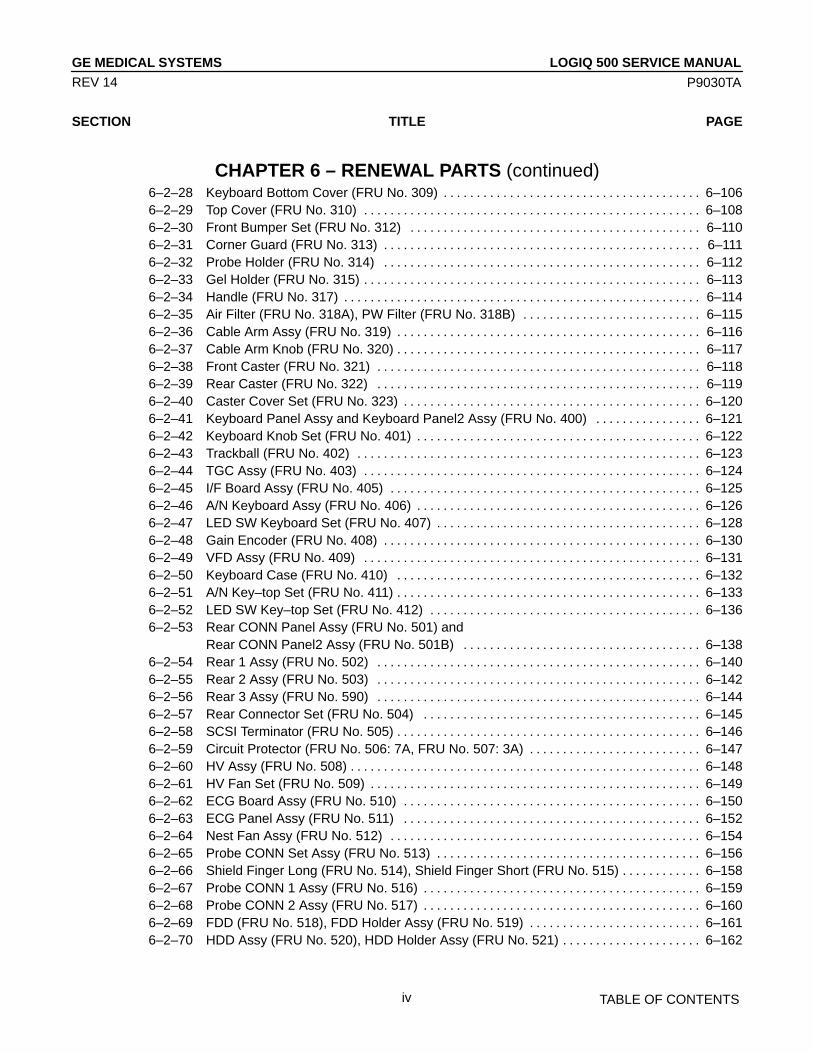
CHAPTER 6 – RENEWAL PARTS (continued)6–2–28 Keyboard Bottom Cover (FRU No. 309) 6–106. . . . . . . . . . . . . . . . . . . . . . . . . . . . . . . . . . . . . . . 6–2–29 Top Cover (FRU No. 310) 6–108. . . . . . . . . . . . . . . . . . . . . . . . . . . . . . . . . . . . . . . . . . . . . . . . . . . 6–2–30 Front Bumper Set (FRU No. 312) 6–110. . . . . . . . . . . . . . . . . . . . . . . . . . . . . . . . . . . . . . . . . . . . 6–2–31 Corner Guard (FRU No. 313) 6–111. . . . . . . . . . . . . . . . . . . . . . . . . . . . . . . . . . . . . . . . . . . . . . . . 6–2–32 Probe Holder (FRU No. 314) 6–112. . . . . . . . . . . . . . . . . . . . . . . . . . . . . . . . . . . . . . . . . . . . . . . . 6–2–33 Gel Holder (FRU No. 315) 6–113. . . . . . . . . . . . . . . . . . . . . . . . . . . . . . . . . . . . . . . . . . . . . . . . . . . 6–2–34 Handle (FRU No. 317) 6–114. . . . . . . . . . . . . . . . . . . . . . . . . . . . . . . . . . . . . . . . . . . . . . . . . . . . . . 6–2–35 Air Filter (FRU No. 318A), PW Filter (FRU No. 318B) 6–115. . . . . . . . . . . . . . . . . . . . . . . . . . . 6–2–36 Cable Arm Assy (FRU No. 319) 6–116. . . . . . . . . . . . . . . . . . . . . . . . . . . . . . . . . . . . . . . . . . . . . . 6–2–37 Cable Arm Knob (FRU No. 320) 6–117. . . . . . . . . . . . . . . . . . . . . . . . . . . . . . . . . . . . . . . . . . . . . . 6–2–38 Front Caster (FRU No. 321) 6–118. . . . . . . . . . . . . . . . . . . . . . . . . . . . . . . . . . . . . . . . . . . . . . . . . 6–2–39 Rear Caster (FRU No. 322) 6–119. . . . . . . . . . . . . . . . . . . . . . . . . . . . . . . . . . . . . . . . . . . . . . . . . 6–2–40 Caster Cover Set (FRU No. 323) 6–120. . . . . . . . . . . . . . . . . . . . . . . . . . . . . . . . . . . . . . . . . . . . . 6–2–41 Keyboard Panel Assy and Keyboard Panel2 Assy (FRU No. 400) 6–121. . . . . . . . . . . . . . . . 6–2–42 Keyboard Knob Set (FRU No. 401) 6–122. . . . . . . . . . . . . . . . . . . . . . . . . . . . . . . . . . . . . . . . . . . 6–2–43 Trackball (FRU No. 402) 6–123. . . . . . . . . . . . . . . . . . . . . . . . . . . . . . . . . . . . . . . . . . . . . . . . . . . . 6–2–44 TGC Assy (FRU No. 403) 6–124. . . . . . . . . . . . . . . . . . . . . . . . . . . . . . . . . . . . . . . . . . . . . . . . . . . 6–2–45 I/F Board Assy (FRU No. 405) 6–125. . . . . . . . . . . . . . . . . . . . . . . . . . . . . . . . . . . . . . . . . . . . . . . 6–2–46 A/N Keyboard Assy (FRU No. 406) 6–126. . . . . . . . . . . . . . . . . . . . . . . . . . . . . . . . . . . . . . . . . . . 6–2–47 LED SW Keyboard Set (FRU No. 407) 6–128. . . . . . . . . . . . . . . . . . . . . . . . . . . . . . . . . . . . . . . . 6–2–48 Gain Encoder (FRU No. 408) 6–130. . . . . . . . . . . . . . . . . . . . . . . . . . . . . . . . . . . . . . . . . . . . . . . . 6–2–49 VFD Assy (FRU No. 409) 6–131. . . . . . . . . . . . . . . . . . . . . . . . . . . . . . . . . . . . . . . . . . . . . . . . . . . 6–2–50 Keyboard Case (FRU No. 410) 6–132. . . . . . . . . . . . . . . . . . . . . . . . . . . . . . . . . . . . . . . . . . . . . . 6–2–51 A/N Key–top Set (FRU No. 411) 6–133. . . . . . . . . . . . . . . . . . . . . . . . . . . . . . . . . . . . . . . . . . . . . . 6–2–52 LED SW Key–top Set (FRU No. 412) 6–136. . . . . . . . . . . . . . . . . . . . . . . . . . . . . . . . . . . . . . . . . 6–2–53 Rear CONN Panel Assy (FRU No. 501) and
Rear CONN Panel2 Assy (FRU No. 501B) 6–138. . . . . . . . . . . . . . . . . . . . . . . . . . . . . . . . . . . . 6–2–54 Rear 1 Assy (FRU No. 502) 6–140. . . . . . . . . . . . . . . . . . . . . . . . . . . . . . . . . . . . . . . . . . . . . . . . . 6–2–55 Rear 2 Assy (FRU No. 503) 6–142. . . . . . . . . . . . . . . . . . . . . . . . . . . . . . . . . . . . . . . . . . . . . . . . . 6–2–56 Rear 3 Assy (FRU No. 590) 6–144. . . . . . . . . . . . . . . . . . . . . . . . . . . . . . . . . . . . . . . . . . . . . . . . . 6–2–57 Rear Connector Set (FRU No. 504) 6–145. . . . . . . . . . . . . . . . . . . . . . . . . . . . . . . . . . . . . . . . . . 6–2–58 SCSI Terminator (FRU No. 505) 6–146. . . . . . . . . . . . . . . . . . . . . . . . . . . . . . . . . . . . . . . . . . . . . . 6–2–59 Circuit Protector (FRU No. 506: 7A, FRU No. 507: 3A) 6–147. . . . . . . . . . . . . . . . . . . . . . . . . . 6–2–60 HV Assy (FRU No. 508) 6–148. . . . . . . . . . . . . . . . . . . . . . . . . . . . . . . . . . . . . . . . . . . . . . . . . . . . . 6–2–61 HV Fan Set (FRU No. 509) 6–149. . . . . . . . . . . . . . . . . . . . . . . . . . . . . . . . . . . . . . . . . . . . . . . . . . 6–2–62 ECG Board Assy (FRU No. 510) 6–150. . . . . . . . . . . . . . . . . . . . . . . . . . . . . . . . . . . . . . . . . . . . . 6–2–63 ECG Panel Assy (FRU No. 511) 6–152. . . . . . . . . . . . . . . . . . . . . . . . . . . . . . . . . . . . . . . . . . . . . 6–2–64 Nest Fan Assy (FRU No. 512) 6–154. . . . . . . . . . . . . . . . . . . . . . . . . . . . . . . . . . . . . . . . . . . . . . . 6–2–65 Probe CONN Set Assy (FRU No. 513) 6–156. . . . . . . . . . . . . . . . . . . . . . . . . . . . . . . . . . . . . . . . 6–2–66 Shield Finger Long (FRU No. 514), Shield Finger Short (FRU No. 515) 6–158. . . . . . . . . . . . 6–2–67 Probe CONN 1 Assy (FRU No. 516) 6–159. . . . . . . . . . . . . . . . . . . . . . . . . . . . . . . . . . . . . . . . . . 6–2–68 Probe CONN 2 Assy (FRU No. 517) 6–160. . . . . . . . . . . . . . . . . . . . . . . . . . . . . . . . . . . . . . . . . . 6–2–69 FDD (FRU No. 518), FDD Holder Assy (FRU No. 519) 6–161. . . . . . . . . . . . . . . . . . . . . . . . . . 6–2–70 HDD Assy (FRU No. 520), HDD Holder Assy (FRU No. 521) 6–162. . . . . . . . . . . . . . . . . . . . .
LOGIQ 500 SERVICE MANUALGE MEDICAL SYSTEMS
P9030TA
TABLE OF CONTENTSv
REV 14
SECTION TITLE PAGE
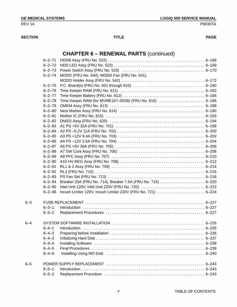
CHAPTER 6 – RENEWAL PARTS (continued)6–2–71 HDDB Assy (FRU No. 522) 6–168. . . . . . . . . . . . . . . . . . . . . . . . . . . . . . . . . . . . . . . . . . . . . . . . . . 6–2–72 HDD LED Assy (FRU No. 523) 6–169. . . . . . . . . . . . . . . . . . . . . . . . . . . . . . . . . . . . . . . . . . . . . . . 6–2–73 Power Switch Assy (FRU No. 525) 6–170. . . . . . . . . . . . . . . . . . . . . . . . . . . . . . . . . . . . . . . . . . . 6–2–74 MODD (FRU No. 540), MODD Fan (FRU No. 541),
MODD Holder Assy (FRU No. 542) 6–172. . . . . . . . . . . . . . . . . . . . . . . . . . . . . . . . . . . . . . . . . . . 6–2–75 P.C. Board(s) (FRU No. 601 through 610) 6–180. . . . . . . . . . . . . . . . . . . . . . . . . . . . . . . . . . . . . 6–2–76 Time Keeper RAM (FRU No. 611) 6–182. . . . . . . . . . . . . . . . . . . . . . . . . . . . . . . . . . . . . . . . . . . . 6–2–77 Time Keeper Battery (FRU No. 612) 6–184. . . . . . . . . . . . . . . . . . . . . . . . . . . . . . . . . . . . . . . . . . 6–2–78 Time Keeper RAM (for MVME167–002B) (FRU No. 616) 6–186. . . . . . . . . . . . . . . . . . . . . . . . 6–2–79 OMEM Assy (FRU No. 613) 6–188. . . . . . . . . . . . . . . . . . . . . . . . . . . . . . . . . . . . . . . . . . . . . . . . . 6–2–80 Nest Mother Assy (FRU No. 614) 6–190. . . . . . . . . . . . . . . . . . . . . . . . . . . . . . . . . . . . . . . . . . . . 6–2–81 Mother IC (FRU No. 615) 6–193. . . . . . . . . . . . . . . . . . . . . . . . . . . . . . . . . . . . . . . . . . . . . . . . . . . 6–2–82 DNID2 Assy (FRU No. 620) 6–194. . . . . . . . . . . . . . . . . . . . . . . . . . . . . . . . . . . . . . . . . . . . . . . . . 6–2–83 A1 PS +5V 32A (FRU No. 701) 6–198. . . . . . . . . . . . . . . . . . . . . . . . . . . . . . . . . . . . . . . . . . . . . . 6–2–84 A2 PS –5.2V 11A (FRU No. 702) 6–200. . . . . . . . . . . . . . . . . . . . . . . . . . . . . . . . . . . . . . . . . . . . . 6–2–85 A3 PS +12V 8.4A (FRU No. 703) 6–202. . . . . . . . . . . . . . . . . . . . . . . . . . . . . . . . . . . . . . . . . . . . . 6–2–86 A4 PS –12V 2.5A (FRU No. 704) 6–204. . . . . . . . . . . . . . . . . . . . . . . . . . . . . . . . . . . . . . . . . . . . . 6–2–87 A5 PS +5V 30A (FRU No. 705) 6–206. . . . . . . . . . . . . . . . . . . . . . . . . . . . . . . . . . . . . . . . . . . . . . 6–2–88 A7 SW Cont Assy (FRU No. 706) 6–208. . . . . . . . . . . . . . . . . . . . . . . . . . . . . . . . . . . . . . . . . . . . 6–2–89 A8 PFC Assy (FRU No. 707) 6–210. . . . . . . . . . . . . . . . . . . . . . . . . . . . . . . . . . . . . . . . . . . . . . . . 6–2–90 A10 HV REG Assy (FRU No. 708) 6–212. . . . . . . . . . . . . . . . . . . . . . . . . . . . . . . . . . . . . . . . . . . . 6–2–91 RL1 & 2 Assy (FRU No. 709) 6–214. . . . . . . . . . . . . . . . . . . . . . . . . . . . . . . . . . . . . . . . . . . . . . . . 6–2–92 RL3 (FRU No. 710) 6–216. . . . . . . . . . . . . . . . . . . . . . . . . . . . . . . . . . . . . . . . . . . . . . . . . . . . . . . . . 6–2–93 PS Fan Set (FRU No. 713) 6–218. . . . . . . . . . . . . . . . . . . . . . . . . . . . . . . . . . . . . . . . . . . . . . . . . . 6–2–94 Breaker 20A (FRU No. 714), Breaker 7.5A (FRU No. 715) 6–220. . . . . . . . . . . . . . . . . . . . . . . 6–2–95 Inlet Unit 120V, Inlet Unit 220V (FRU No. 720) 6–222. . . . . . . . . . . . . . . . . . . . . . . . . . . . . . . . . 6–2–96 Inrush Limiter 120V, Inrush Limiter 220V (FRU No. 721) 6–224. . . . . . . . . . . . . . . . . . . . . . . . .
6–3 FUSE REPLACEMENT 6–227. . . . . . . . . . . . . . . . . . . . . . . . . . . . . . . . . . . . . . . . . . . . . . . . . . . . . . . . . . . . . . 6–3–1 Introduction 6–227. . . . . . . . . . . . . . . . . . . . . . . . . . . . . . . . . . . . . . . . . . . . . . . . . . . . . . . . . . . . . . . 6–3–2 Replacement Procedures 6–227. . . . . . . . . . . . . . . . . . . . . . . . . . . . . . . . . . . . . . . . . . . . . . . . . . .
6–4 SYSTEM SOFTWARE INSTALLATION 6–235. . . . . . . . . . . . . . . . . . . . . . . . . . . . . . . . . . . . . . . . . . . . . . . . 6–4–1 Introduction 6–235. . . . . . . . . . . . . . . . . . . . . . . . . . . . . . . . . . . . . . . . . . . . . . . . . . . . . . . . . . . . . . . 6–4–2 Preparing before Installation 6–236. . . . . . . . . . . . . . . . . . . . . . . . . . . . . . . . . . . . . . . . . . . . . . . . . 6–4–3 Initializing Hard Disk 6–237. . . . . . . . . . . . . . . . . . . . . . . . . . . . . . . . . . . . . . . . . . . . . . . . . . . . . . . . 6–4–4 Installing Software 6–238. . . . . . . . . . . . . . . . . . . . . . . . . . . . . . . . . . . . . . . . . . . . . . . . . . . . . . . . . 6–4–5 Final Procedures 6–239. . . . . . . . . . . . . . . . . . . . . . . . . . . . . . . . . . . . . . . . . . . . . . . . . . . . . . . . . . . 6–4–6 Installing Using MO Disk 6–240. . . . . . . . . . . . . . . . . . . . . . . . . . . . . . . . . . . . . . . . . . . . . . . . . . .
6–5 POWER SUPPLY REPLACEMENT 6–243. . . . . . . . . . . . . . . . . . . . . . . . . . . . . . . . . . . . . . . . . . . . . . . . . . . 6–5–1 Introduction 6–243. . . . . . . . . . . . . . . . . . . . . . . . . . . . . . . . . . . . . . . . . . . . . . . . . . . . . . . . . . . . . . . 6–5–2 Replacement Procedure 6–243. . . . . . . . . . . . . . . . . . . . . . . . . . . . . . . . . . . . . . . . . . . . . . . . . . . .

LOGIQ 500 SERVICE MANUALGE MEDICAL SYSTEMS
P9030TA
TABLE OF CONTENTSvi
REV 14
SECTION TITLE PAGE
CHAPTER 6 – RENEWAL PARTS (continued)
6–6 REPLACING 2.5–INCH HDD ASSY WITH 3.5–INCH HDD ASSY 6–251. . . . . . . . . . . . . . . . . . . . . . . . . 6–6–1 Introduction 6–251. . . . . . . . . . . . . . . . . . . . . . . . . . . . . . . . . . . . . . . . . . . . . . . . . . . . . . . . . . . . . . . 6–6–2 Time Required 6–251. . . . . . . . . . . . . . . . . . . . . . . . . . . . . . . . . . . . . . . . . . . . . . . . . . . . . . . . . . . . . 6–6–3 Parts Required 6–251. . . . . . . . . . . . . . . . . . . . . . . . . . . . . . . . . . . . . . . . . . . . . . . . . . . . . . . . . . . . 6–6–4 Procedures 6–251. . . . . . . . . . . . . . . . . . . . . . . . . . . . . . . . . . . . . . . . . . . . . . . . . . . . . . . . . . . . . . . .
CHAPTER 7 – PERIODIC MAINTENANCE
7–1 INTRODUCTION 7–3. . . . . . . . . . . . . . . . . . . . . . . . . . . . . . . . . . . . . . . . . . . . . . . . . . . . . . . . . . . . . . . . . . . . . 7–1–1 Periodic Maintenance 7–3. . . . . . . . . . . . . . . . . . . . . . . . . . . . . . . . . . . . . . . . . . . . . . . . . . . . . . . . .
7–2 PERIODIC MAINTENANCE PROCEDURE 7–3. . . . . . . . . . . . . . . . . . . . . . . . . . . . . . . . . . . . . . . . . . . . . . 7–2–1 Visual Inspection 7–3. . . . . . . . . . . . . . . . . . . . . . . . . . . . . . . . . . . . . . . . . . . . . . . . . . . . . . . . . . . . . 7–2–2 Cleaning 7–4. . . . . . . . . . . . . . . . . . . . . . . . . . . . . . . . . . . . . . . . . . . . . . . . . . . . . . . . . . . . . . . . . . . . 7–2–3 Measurement 7–5. . . . . . . . . . . . . . . . . . . . . . . . . . . . . . . . . . . . . . . . . . . . . . . . . . . . . . . . . . . . . . . . 7–2–4 User Data Backup 7–6. . . . . . . . . . . . . . . . . . . . . . . . . . . . . . . . . . . . . . . . . . . . . . . . . . . . . . . . . . . . 7–2–5 Note 7–6. . . . . . . . . . . . . . . . . . . . . . . . . . . . . . . . . . . . . . . . . . . . . . . . . . . . . . . . . . . . . . . . . . . . . . . .
7–3 ELECTRICAL SAFETY TESTS 7–7. . . . . . . . . . . . . . . . . . . . . . . . . . . . . . . . . . . . . . . . . . . . . . . . . . . . . . . . . 7–3–1 Outlet Test Wiring Arrangement 7–7. . . . . . . . . . . . . . . . . . . . . . . . . . . . . . . . . . . . . . . . . . . . . . . . 7–3–2 Grounding Continuity 7–8. . . . . . . . . . . . . . . . . . . . . . . . . . . . . . . . . . . . . . . . . . . . . . . . . . . . . . . . . 7–3–3 Chassis Leakage Current Test 7–9. . . . . . . . . . . . . . . . . . . . . . . . . . . . . . . . . . . . . . . . . . . . . . . . . 7–3–4 Probe Leakage Current Test 7–12. . . . . . . . . . . . . . . . . . . . . . . . . . . . . . . . . . . . . . . . . . . . . . . . . . 7–3–5 ECG Leakage Current Test 7–16. . . . . . . . . . . . . . . . . . . . . . . . . . . . . . . . . . . . . . . . . . . . . . . . . . . 7–3–6 When There’s Too Much Leakage Current 7–20. . . . . . . . . . . . . . . . . . . . . . . . . . . . . . . . . . . . . .
CHAPTER 8 – INSTALLATION FOR OPTIONS
8–1 INTRODUCTION 8–3. . . . . . . . . . . . . . . . . . . . . . . . . . . . . . . . . . . . . . . . . . . . . . . . . . . . . . . . . . . . . . . . . . . . .
LOGIQ 500 SERVICE MANUALGE MEDICAL SYSTEMS
P9030TA
INTRODUCTION1–1
REV 14
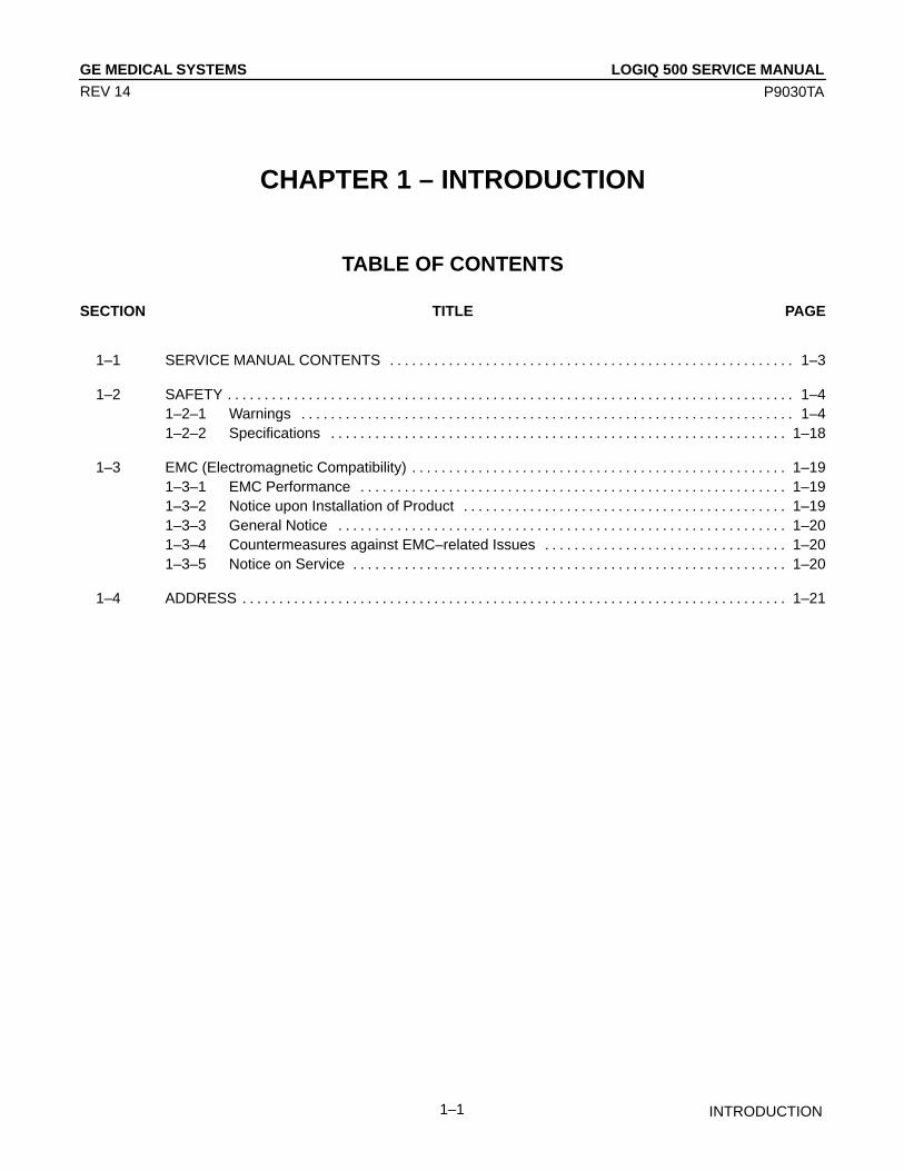
CHAPTER 1 – INTRODUCTION
TABLE OF CONTENTS
SECTION TITLE PAGE
1–1 SERVICE MANUAL CONTENTS 1–3. . . . . . . . . . . . . . . . . . . . . . . . . . . . . . . . . . . . . . . . . . . . . . . . . . . . . . .
1–2 SAFETY 1–4. . . . . . . . . . . . . . . . . . . . . . . . . . . . . . . . . . . . . . . . . . . . . . . . . . . . . . . . . . . . . . . . . . . . . . . . . . . . . 1–2–1 Warnings 1–4. . . . . . . . . . . . . . . . . . . . . . . . . . . . . . . . . . . . . . . . . . . . . . . . . . . . . . . . . . . . . . . . . . . 1–2–2 Specifications 1–18. . . . . . . . . . . . . . . . . . . . . . . . . . . . . . . . . . . . . . . . . . . . . . . . . . . . . . . . . . . . . .
1–3 EMC (Electromagnetic Compatibility) 1–19. . . . . . . . . . . . . . . . . . . . . . . . . . . . . . . . . . . . . . . . . . . . . . . . . . . 1–3–1 EMC Performance 1–19. . . . . . . . . . . . . . . . . . . . . . . . . . . . . . . . . . . . . . . . . . . . . . . . . . . . . . . . . . 1–3–2 Notice upon Installation of Product 1–19. . . . . . . . . . . . . . . . . . . . . . . . . . . . . . . . . . . . . . . . . . . . 1–3–3 General Notice 1–20. . . . . . . . . . . . . . . . . . . . . . . . . . . . . . . . . . . . . . . . . . . . . . . . . . . . . . . . . . . . . 1–3–4 Countermeasures against EMC–related Issues 1–20. . . . . . . . . . . . . . . . . . . . . . . . . . . . . . . . . 1–3–5 Notice on Service 1–20. . . . . . . . . . . . . . . . . . . . . . . . . . . . . . . . . . . . . . . . . . . . . . . . . . . . . . . . . . .
1–4 ADDRESS 1–21. . . . . . . . . . . . . . . . . . . . . . . . . . . . . . . . . . . . . . . . . . . . . . . . . . . . . . . . . . . . . . . . . . . . . . . . . .

LOGIQ 500 SERVICE MANUALGE MEDICAL SYSTEMS
P9030TA
INTRODUCTION1–2
REV 0
This page is left blank intentionally.

LOGIQ 500 SERVICE MANUALGE MEDICAL SYSTEMS
P9030TA
INTRODUCTION1–3
REV 4
1–1 SERVICE MANUAL CONTENTS
This manual provides service information on the LOGIQ 500 Ultrasound Scanning System. It contains the followingchapters:
1. Chapter 1, Introduction: Contains a content summary and warnings;
2. Chapter 2, Installation: Contains physical and electrical requirements that must be considered prior to installa-tion and a complete LOGIQ 500 installation procedure with installation checklist;
3. Chapter 3, System Configuration: Contains system configuration and specifications;
4. Chapter 4, Functional Checks: Contains functional checks that must be performed as part of the installation, oras required during servicing and periodic maintenance;
5. Chapter 5, Diagrams: Contains block diagrams and functional explanations of the LOGIQ 500 electronics;
6. Chapter 6, Renewal Parts: Contains a complete list of replacement parts for the LOGIQ 500 and disassemblyprocedures for all changeable FRU;
7. Chapter 7, Periodic Maintenance: Provides periodic maintenance procedures for the LOGIQ 500.
8. Chapter 8, Installation for Options: is provided to keep the option installation instructions supplied with eachoption.

LOGIQ 500 SERVICE MANUALGE MEDICAL SYSTEMS
P9030TA
INTRODUCTION1–4
REV 12
1–2 SAFETY
1–2–1 Warnings
WARNING!
CAREFULLY READ ALL THE WARNINGS LISTED BELOW!
1. The operator manual should be fully read and understood before operating the LOGIQ 500 and kept nearby forquick reference.
2. Although the ultrasound energy transmitted from the LOGIQ 500 transducer is within AIUM/NEMA standards,unnecessary exposure should be avoided. Only trained personnel should operate the LOGIQ 500.
3. To prevent electrical shock, the LOGIQ 500 should be connected to a properly grounded power receptacle. Donot use a three prong to two prong adapter. This defeats safety grounding.
4. Do not use with Defibrillator when LOGIQ 500 is being operated .
5. Probes are fragile, please handle with care.
6. Concerning Outside Markings, refer to Illustration 1–1 through 1–10.
7. For the cleaning, disinfection, and sterilization, refer to Probe section in LOGIQ 500 User Manual and CautionSheet supplied with each probe.
NOTICE
This medical equipment is approved, in terms of the prevention of radio wave interference, to be usedin hospitals, clinics and other institutions which are environmentally qualified. The use of this equip-ment in an inappropriate environment may cause some electronic interference to radios and televi-sions around the equipment. Proper handling of this equipment is required in order to avoid suchtrouble according to the operator and service manuals.This equipment can be used in residential areas only under the supervision of physicians or qualifiedtechnicians.
CAUTION
Improper performance possibility. Do not use the following devices near this equipment.Cellular phone, radio transceiver, mobile radio transmitter, radio-controlled toy, etc.Use of these devices near this equipment could cause this equipment to perform outside thepublished specifications. Keep power to these devices turned off when near this equipment.

LOGIQ 500 SERVICE MANUALGE MEDICAL SYSTEMS
P9030TA
INTRODUCTION1–5
REV 13
1–2–1 Warnings (continued)
[Consoles with V5.00 y or Later][Consoles with Software prior to V5.00 y]
OUTSIDE MARKINGS OF LOGIQ 500 (For All Units)ILLUSTRATION 1–1
NoteThis caution label has been removed at the installation of the system.

LOGIQ 500 SERVICE MANUALGE MEDICAL SYSTEMS
P9030TA
INTRODUCTION1–6
REV 13
1–2–1 Warnings (continued)
[Consoles with V5.00 y or Later][Consoles with Software prior to V5.00 y]
OUTSIDE MARKINGS OF LOGIQ 500 (For All Units)ILLUSTRATION 1–2
NoteFor further details regarding the cautions above, refer to 2–2–8 MOVING INTO POSITION in Chap-ter 2.

LOGIQ 500 SERVICE MANUALGE MEDICAL SYSTEMS
P9030TA
INTRODUCTION1–7
REV 13
1–2–1 Warnings (continued)
CAUTION
Possible Injury. Placing objects on top of the monitor may cause the monitor to tilt with thefalling objects resulting in injury to the operator. Do not place any objects on the monitor.
[Consoles with V5.00 y or Later][Consoles with Software prior to V5.00 y]
OUTSIDE MARKINGS OF LOGIQ 500 (For All Units)ILLUSTRATION 1–3

LOGIQ 500 SERVICE MANUALGE MEDICAL SYSTEMS
P9030TA
INTRODUCTION1–8
REV 12
1–2–1 Warnings (continued)
OUTSIDE MARKINGS OF LOGIQ 500 (For USA/Asia)ILLUSTRATION 1–4
NoteThe ETL label described in ILLUSTRATION 1–4 is attached on the system software version 2.00 orlater console. The system software 1.20 or former console has the different style of ETL label.For the symbols shown in the illustration above, refer to latter pages in this chapter.The CAUTION label for the radio influence is attached on the console from April, 1996.

LOGIQ 500 SERVICE MANUALGE MEDICAL SYSTEMS
P9030TA
INTRODUCTION1–9
REV 12
1–2–1 Warnings (continued)
OUTSIDE MARKINGS OF LOGIQ 500 (For Europe) [a]ILLUSTRATION 1–5
NoteFor the symbols shown in the illustration above, refer to latter pages in this chapter.
LOGIQ 500 SERVICE MANUALGE MEDICAL SYSTEMS
P9030TA
INTRODUCTION1–10
REV 14
1–2–1 Warnings (continued)
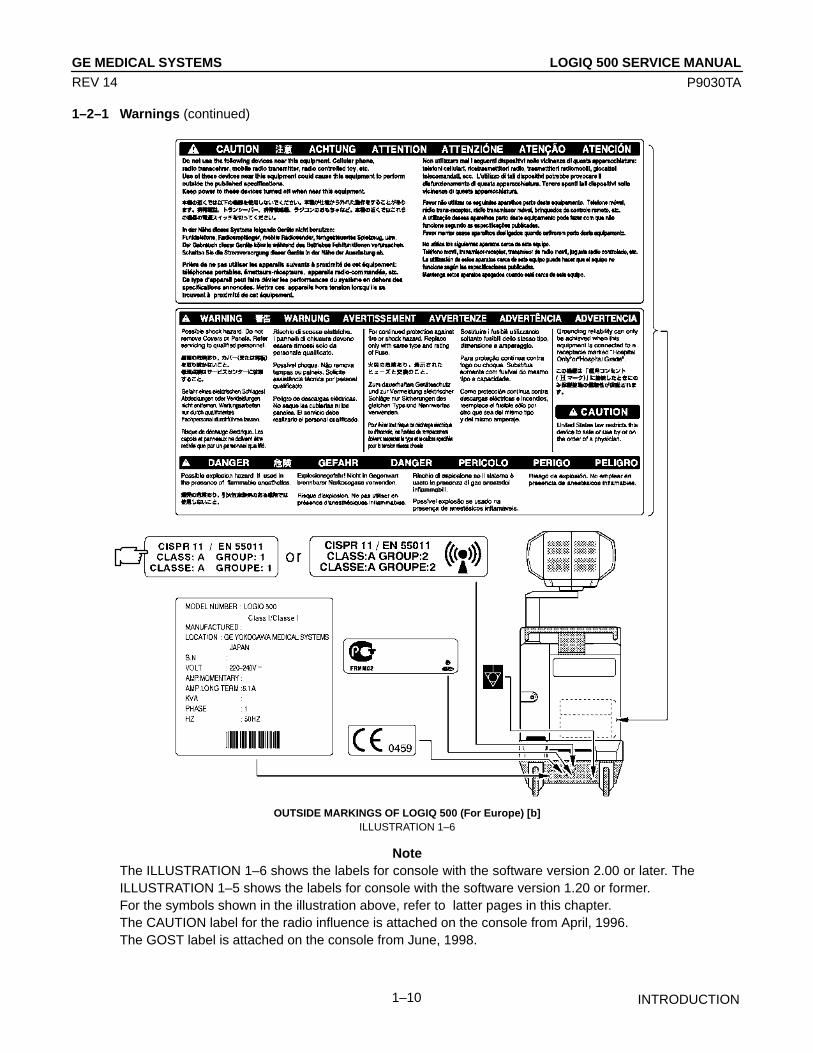
OUTSIDE MARKINGS OF LOGIQ 500 (For Europe) [b]ILLUSTRATION 1–6
NoteThe ILLUSTRATION 1–6 shows the labels for console with the software version 2.00 or later. TheILLUSTRATION 1–5 shows the labels for console with the software version 1.20 or former.For the symbols shown in the illustration above, refer to latter pages in this chapter.The CAUTION label for the radio influence is attached on the console from April, 1996.The GOST label is attached on the console from June, 1998.
LOGIQ 500 SERVICE MANUALGE MEDICAL SYSTEMS
P9030TA
INTRODUCTION1–11
REV 14
1–2–1 Warnings (continued)
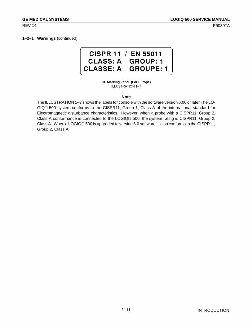
CE Marking Label (For Europe)ILLUSTRATION 1–7
NoteThe ILLUSTRATION 1–7 shows the labels for console with the software version 6.00 or later.The LO-GIQ 500 system conforms to the CISPR11, Group 1, Class A of the international standard forElectromagnetic disturbance characteristics. However, when a probe with a CISPR11, Group 2,Class A conformance is connected to the LOGIQ 500, the system rating is CISPR11, Group 2,Class A. When a LOGIQ 500 is upgraded to version 6.0 software, it also conforms to the CISPR11,Group 2, Class A.
LOGIQ 500 SERVICE MANUALGE MEDICAL SYSTEMS
P9030TA
INTRODUCTION1–12
REV 14
1–2–1 Warnings (continued)
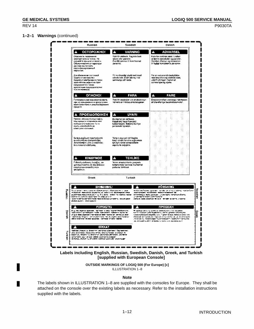
Labels including English, Russian, Swedish, Danish, Greek, and Turkish[supplied with European Console]
OUTSIDE MARKINGS OF LOGIQ 500 (For Europe) [c]ILLUSTRATION 1–8
NoteThe labels shown in ILLUSTRATION 1–8 are supplied with the consoles for Europe. They shall beattached on the console over the existing labels as necessary. Refer to the installation instructionssupplied with the labels.
LOGIQ 500 SERVICE MANUALGE MEDICAL SYSTEMS
P9030TA
INTRODUCTION1–13
REV 14
1–2–1 Warnings (continued)
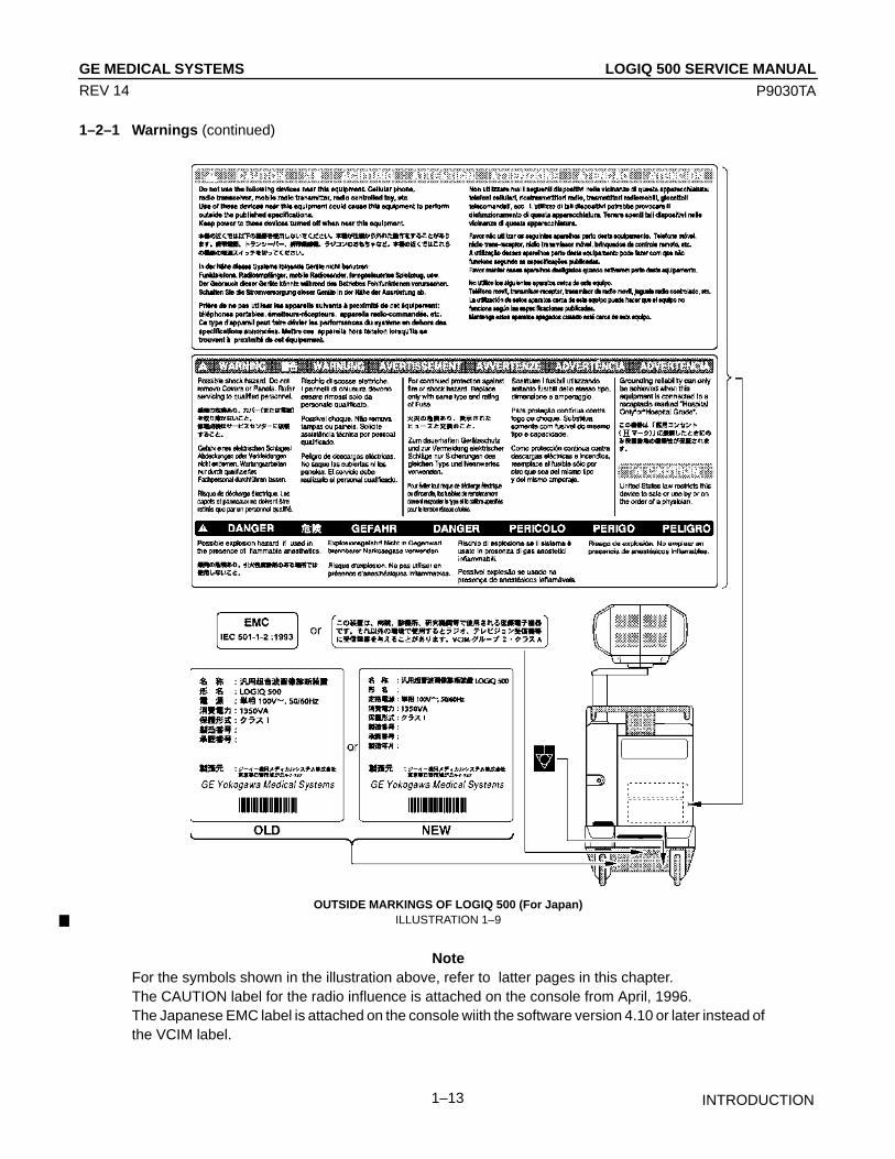
OUTSIDE MARKINGS OF LOGIQ 500 (For Japan)ILLUSTRATION 1–9
NoteFor the symbols shown in the illustration above, refer to latter pages in this chapter.The CAUTION label for the radio influence is attached on the console from April, 1996.The Japanese EMC label is attached on the console wiith the software version 4.10 or later instead ofthe VCIM label.

LOGIQ 500 SERVICE MANUALGE MEDICAL SYSTEMS
P9030TA
INTRODUCTION1–14
REV 14
1–2–1 Warnings (continued)
CAUTION
Do not use a Defibrillator simultaneously with the ECG, as its excessive voltage will damagethe signal input block of the ECG unit.
OUTSIDE MARKINGS OF LOGIQ 500 (For Units with ECG)ILLUSTRATION 1–10
NoteThis label is attached only on the LOGIQ 500 console with the optional ECG unit.
Labels including English, Russian, Swedish, Danish, Greek, and Turkish[supplied with European Console]
EUROPEAN LANGUAGE LABEL ON ECG LABELILLUSTRATION 1–11
NoteThe labels shown in ILLUSTRATION 1–11 are supplied with the consoles for Europe. They shall beattached on the console over the existing labels as necessary. Refer to the installation instructionssupplied with the labels.

LOGIQ 500 SERVICE MANUALGE MEDICAL SYSTEMS
P9030TA
INTRODUCTION1–15
REV 14
1–2–1 Warnings (continued)
NOTE: Same labels are attached on both left and right side of the transformer box inside the side covers
MARKINGS OF LOGIQ 500 (INSIDE SIDE COVERS)ILLUSTRATION 1–12
NoteFor further details, refer to 4–4 POWER SUPPLY ADJUSTMENT in Chapter 4.

LOGIQ 500 SERVICE MANUALGE MEDICAL SYSTEMS
P9030TA
INTRODUCTION1–16
REV 14
1–2–1 Warnings (Continued)
The following table describes the purpose and location of safety labels and other important information provided on theequipment.
Label/Symbol Purpose/Meaning Location
Identification and RatingPlate
• Manufacturer’s name and address• Date of manufacture• Model and serial numbers• Electrical ratings
Used to indicate the degree of safetyor protection.
Indicates the degree of protectionprovided by the enclosure per IEC529. IPX1 indicates drip proof.
Equipment Type BF (man in the boxsymbol) IEC 878–02–03 indicates BType equipment having a floating ap-plied part.
Equipment Type CF (heart in the boxsymbol) IEC 878–02–05 indicatesequipment having a floating appliedpart having a degree of protectionsuitable for direct cardiac contact.
Laboratory logo or labels denotingconformance with industry safetystandards such as UL or IEC.
This precaution is intended to preventinjury that may result if one personattempt to move the unit considerabledistances or on an incline due to theweight of the unit.
The system is not designed for usewith flammable anesthetic gases.
”CAUTION” The equilateral triangle isusually used in combination with oth-er symbols to advise or warn theuser.
• ATTENTION – Consult accompa-nying documents ” is intended to alertthe user to refer to the operatormanual or other instructions whencomplete information cannot be pro-vided on the label.
Type/Class Label
IP Code(IPX1)
Device Listing/Certification Labels
CAUTION – This unitweighs...Special care must beused to avoid...”
”DANGER – Risk of explosionused in...”
Rear of console near powerinlet
Footswitch
Probe connectorsand PCG connector
ECG connector and surgicalprobes
Rear of console
On the console where easilyseen during transport
Rear of console
Various
Various

LOGIQ 500 SERVICE MANUALGE MEDICAL SYSTEMS
P9030TA
INTRODUCTION1–17
REV 14
1–2–1 Warnings (Continued)
Rear of systemAdjacent to mains switch
Label/Symbol Purpose/Meaning Location
• ”CAUTION – Dangerous voltage”(the lightning flash with arrowhead inequilateral triangle) is used to indi-cate electric shock hazards.
• ”Mains OFF” Indicates the poweroff position of the mains powerswitch.
• ”OFF/Standby” Indicates the pow-er off/standby position of the powerswitch.
CAUTIONThis Power Switch DOES NOT ISO-LATE Mains Supply
• ”Mains ON” Indicates the poweron position of the mains powerswitch.
• ”ON” Indicates the power on posi-tion of the power switch.
CAUTIONThis Power Switch DOES NOT ISO-LATE Mains Supply
• ”Protective Earth” Indicates theprotective earth (grounding) terminal.
• ”Equipotentiality” Indicates the ter-minal to be used for connecting equi-potential conductors when intercon-necting (grounding) with other equip-ment.
Adjacent toOn–Off/Standby Switch
Not used
Rear of console
Various
Rear of systemAdjacent to mains switch
Adjacent toOn–Off/Standby Switch

LOGIQ 500 SERVICE MANUALGE MEDICAL SYSTEMS
P9030TA
INTRODUCTION1–18
REV 14
1–2–2 Specifications
Type of protection against electric shock: Class I EQUIPMENT (*1)
Degree of protection against electric shock: Type BF EQUIPMENT (*2) (Except ECG)Type CF EQUIPMENT (*3) (ECG Only)
Ordinary EquipmentContinuous Operation
*1. Class I EQUIPMENTEQUIPMENT in which protection against electric shock does not rely on BASIC INSULATION only, but whichincludes an additional safety precaution in that means are provided for the connection of the EQUIPMENT tothe protective earth conductor in the fixed wiring of the installation in such a way that ACCESSIBLE METALPARTS cannot become LIVE in the event of a failure of the BASIC INSULATION.
*2. Type BF EQUIPMENTTYPE B EQUIPMENT with an F–TYPE APPLIED PARTTYPE B EQUIPMENT: EQUIPMENT providing a particular degree of protection against electric shock, partic-ularly regarding:
– allowable LEAKAGE CURRENT;
Normal mode Single failure mode
Patient leakage current Less than 100µA Less than 500µA
*3. Type CF EQUIPMENTEQUIPMENT providing a particular degree of protection higher than that for TYPE OF BF EQUIPMENTagainst electric shock particularly regarding allowable LEAKAGE CURRENT, and having an F–TYPE AP-PLIED PART.
– allowable LEAKAGE CURRENT;
Normal mode Single failure mode
Patient leakage current Less than 10µA Less than 50µA

LOGIQ 500 SERVICE MANUALGE MEDICAL SYSTEMS
P9030TA
INTRODUCTION1–19
REV 14
1–3 EMC (Electromagnetic Compatibility)
1–3–1 EMC Performance
All types of electronic equipment may characteristically cause electromagnetic interference with other equipment, ei-ther through air or connecting cables. The term EMC (Electromagnetic Compatibility) indicates capability of the equip-ment, which curbs electromagnetic influence from other equipment and at the same time does not affect other equip-ment with similar electromagnetic radiation from itself.
This product is designed to fully comply with the EN60601–1–2 (IEC601–1–2), in Medical electrical equipment EMCregulations.
NoteManufacturer built consoles with version 2.00 software or later conform with EN60601–1–2.Consoles upgraded to version 2.00 or later software (using optional upgrade kits) will not conform toEN60601–1–2.
Proper installation following this service manual is required in order to achieve the full EMC performance of the prod-uct.
The product must be installed as stipulated in 1–3–2, Notice upon Installation of Product.
In case of issues related to EMC, please follow procedures stated in 1–3–4, Countermeasures against EMC-relatedIssues.
1–3–2 Notice upon Installation of Product
1) Use either power supply cords provided by GEMS or ones designated by GEMS. Products equipped withpower source plug should be plugged into the fixed power socket which has the protective grounding conduc-tor.
Connect a three-pole plug to a three-pole socket without using a three-pole-to-two-pole converter.
2) Locate the equipment as far as possible from other electronic equipment.
3) Be sure to use either any cables provided by GEMS or ones designated by GEYMS. Wire these cables follow-ing these installation procedures.
(Example) Wire power cables separately from signal cables.
4) Lay out the main equipment and other peripherals following the installation procedures described in Chapter2,INSTALLATION.

LOGIQ 500 SERVICE MANUALGE MEDICAL SYSTEMS
P9030TA
INTRODUCTION1–20
REV 14
1–3–3 General Notice
1) Designation of Peripheral Equipment Connectable to This Product
The equipment which conforms to EM60601–1–2 (IEC601–1–2), can be hooked up to the product withoutcompromising its EMC performance.
Avoid using other equipment. Failure to comply with this instruction may result in poor EMC performance ofthe product.
2) Notice against User Modification
Never modify this product. Unilateral user modification may cause degradation in EMC performance.Modification of the product includes:
a) Changes in cables (length, material, wiring etc.)
b) Changes in system installation/layout
c) Changes in system configuration/components
d) Changes in means of fixing system/parts (cover open/close, cover screwing)
3) Operate the system with all covers closed. If you open any cover for some reason, be sure to shut it beforestarting/resuming operation.
Operating the system with any cover open may affect EMC performance.
1–3–4 Countermeasures against EMC-related Issues
Generally it is very difficult to grapple with issues related to EMC. It may take much time and cost.
General countermeasuresElectromagnetic interference with other equipment
1) Electromagnetic interference may be alleviated by positioning other equipment far from the system.
2) Electromagnetic interference may be mitigated by changing the relative location (installation angle) betweenthe system and other equipment.
3) Electromagnetic interference may be eased by changing wiring locations of power/signal cables of otherequipment.
4) Electromagnetic influence may be reduced by altering the path of power supply for other equipment.
1–3–5 Notice on Service
1) Ensure all screws are tight after servicing. Loose screws may cause degradation in EMC performance.
2) In case the high frequency gasket of this system is broken, replace it with a new one immediately.
LOGIQ 500 SERVICE MANUALGE MEDICAL SYSTEMS
P9030TA
INTRODUCTION1–21
REV 14
1–4 ADDRESS
This system is not repairable by the customer. If this equipment does not work as indicated in the Operator Manual,please contact your service support center. If the service engineer needs additional information to repair this equip-ment, please contact the following address (The necessary information will be provided to the Service Engineer asneeded):
GE Medical Systems Ultrasound Business Group4855 W. Electric Ave., Milwaukee, WI 53219USA/CANADA TEL: (1) 800–321–7937 FAX: (1) 414–647–4125
LATIN & SOUTH AMERICATEL: (1) 414–524–5300
GE Ultrasound EuropeGE Ultraschall Deutschland GmbH & Co. KGBeethovenstr. 23942655 Solingen, GERMANYTEL: OLC–Europe Toll Free Numbers
orGeneral Imaging Hotline (49) (212) 2802 207Cardiac Hotline (49) (212) 2802 208
FAX: (49) (212) 2802 431
GE YOKOGAWA MEDICAL SYSTEMSOn–Line Center (OLC), AsiaUltrasound Group67–4 Takakura–cho, Hachioji–shi, Tokyo, 192–0033JAPANTEL: (81) 426–48–2940FAX: (81) 426–48–2905

LOGIQ 500 SERVICE MANUALGE MEDICAL SYSTEMS
P9030TA
INTRODUCTION1–22
REV 14
This page is left blank intentionally.

LOGIQ 500 SERVICE MANUALGE MEDICAL SYSTEMS
P9030TA
INSTALLATION2–1
REV 10
CHAPTER 2 – INSTALLATION
TABLE OF CONTENTS
SECTION TITLE PAGE
2–1 PREINSTALLATION 2–3. . . . . . . . . . . . . . . . . . . . . . . . . . . . . . . . . . . . . . . . . . . . . . . . . . . . . . . . . . . . . . . . . . 2–1–1 Introduction 2–3. . . . . . . . . . . . . . . . . . . . . . . . . . . . . . . . . . . . . . . . . . . . . . . . . . . . . . . . . . . . . . . . . 2–1–2 Power Line Requirements 2–3. . . . . . . . . . . . . . . . . . . . . . . . . . . . . . . . . . . . . . . . . . . . . . . . . . . . . 2–1–3 Physical Specifications 2–4. . . . . . . . . . . . . . . . . . . . . . . . . . . . . . . . . . . . . . . . . . . . . . . . . . . . . . . 2–1–4 Recommended Ultrasound Room Layout 2–5. . . . . . . . . . . . . . . . . . . . . . . . . . . . . . . . . . . . . . .
2–2 INSTALLATION 2–8. . . . . . . . . . . . . . . . . . . . . . . . . . . . . . . . . . . . . . . . . . . . . . . . . . . . . . . . . . . . . . . . . . . . . . . 2–2–1 Introduction 2–8. . . . . . . . . . . . . . . . . . . . . . . . . . . . . . . . . . . . . . . . . . . . . . . . . . . . . . . . . . . . . . . . . 2–2–2 Average Installation Time 2–8. . . . . . . . . . . . . . . . . . . . . . . . . . . . . . . . . . . . . . . . . . . . . . . . . . . . . 2–2–3 Installation Warnings 2–8. . . . . . . . . . . . . . . . . . . . . . . . . . . . . . . . . . . . . . . . . . . . . . . . . . . . . . . . . 2–2–4 Checking the Components 2–8. . . . . . . . . . . . . . . . . . . . . . . . . . . . . . . . . . . . . . . . . . . . . . . . . . . . 2–2–5 Unpacking LOGIQ 500 2–9. . . . . . . . . . . . . . . . . . . . . . . . . . . . . . . . . . . . . . . . . . . . . . . . . . . . . . . . 2–2–6 MTZ Probe Holder Installation 2–11. . . . . . . . . . . . . . . . . . . . . . . . . . . . . . . . . . . . . . . . . . . . . . . . 2–2–7 Transducer Connection 2–12. . . . . . . . . . . . . . . . . . . . . . . . . . . . . . . . . . . . . . . . . . . . . . . . . . . . . . 2–2–8 Moving into Position 2–13. . . . . . . . . . . . . . . . . . . . . . . . . . . . . . . . . . . . . . . . . . . . . . . . . . . . . . . . . 2–2–9 Adjusting System Clock 2–13. . . . . . . . . . . . . . . . . . . . . . . . . . . . . . . . . . . . . . . . . . . . . . . . . . . . . . 2–2–10 Product Locator Installation Card 2–14. . . . . . . . . . . . . . . . . . . . . . . . . . . . . . . . . . . . . . . . . . . . . .

LOGIQ 500 SERVICE MANUALGE MEDICAL SYSTEMS
P9030TA
INSTALLATION2–2
REV 0
This page is left blank intentionally.

LOGIQ 500 SERVICE MANUALGE MEDICAL SYSTEMS
P9030TA
INSTALLATION2–3
REV 4
2–1 PREINSTALLATION
2–1–1 Introduction
This section describes various general electrical, operational, and environmental considerations that must be consid-ered before installing the LOGIQ 500 Ultrasound unit.
2–1–2 Power Line Requirements
The following power line parameters should be monitored for one week before installation. We recommend that youuse an analyzer Dranetz Model 606–3 or Dranetz Model 626:
PARAMETER : LIMITS
Voltage Range : Japan. : 100 VAC ±10% (90–110 VAC): Europe : 220–240 VAC ±10% (198–264 VAC)
USA : 115 VAC ±10% (103–127 VAC)
Power : Japan : MAX. 1350 VA: Europe : MAX. 1350 VA: USA : MAX. 1350VA
Line Frequency : All applications : 50/60Hz (±2Hz)
Power Transients : Less than 25 % of nominal peak voltage for less than 1 millisecond for any type oftransient, including line frequency, synchronous, asynchronous, or aperiodictransients.
Decaying Oscillation : Less than 15 % of peak voltage for less than 1 millisecond.
LOGIQ 500 SERVICE MANUALGE MEDICAL SYSTEMS
P9030TA
INSTALLATION2–4
REV 12
2–1–3 Physical Specifications
The LOGIQ 500 (excluding accessories) weighs 180 kg (397 lbs). See Chapter 3, ILLUSTRATION 3–1 for dimen-sions.
NoteThe weight of the console with software version 5.00y or later is approximately 192 kg (423 lbs).The weight of the Tall–version console with software version 5.00y or later is approximately 200 kg(441 lbs).
Operating Conditions
The LOGIQ 500 is designed to operate within a temperature range of 10 degrees C to 40 degrees C (50 degrees F to104 degrees F), and a relative humidity range of 30 % to 85 % (Non–condensing).
Patient Comfort
Concerning permissible operating temperature and humidity tolerances, we recommend that ambient room tempera-ture should be maintained between 20 to 26 degrees C (68 to 79 degrees F), Humidity should be maintained between50 % and 70 % for patient comfort during ultrasound scanning.
Electromagnetic Interference (EMI)
Ultrasound machines are susceptible to interference from the radio frequencies, magnetic fields, and transients in theair or power leads. Possible EMI sources should be identified. Electrical and electronic equipment may produce EMIunintentionally as the result of a malfunction. These sources include medical lasers, cauterizing guns, computers,monitors, fans, gel warmers, microwave ovens, and cellular phones. The presence of broadcast station or van mayalso cause interference.
Carefully read the following precautions before installing the unit.
1. Connect the power plug for any other equipment into the fixed outlet with ground wire.
2. Securely connect any equipment with permanent ground connection to the earth ground furnished in the building.
3. Install the unit as far from any electrical or electronic equipment as possible.
If any EMI troubles are known or suspected to be present, try to deal with the equipment suspected to have influenceon the Ultrasound machine as follows:
1. Move the ultrasound machine as far from the equipment as possible.
2. Change the arrangement of the equipment in the room.
3. Plug the equipment into other outlet.
4. Move the power cable or signal cable connected with the equipment.
Securely re–tighten drive any screws for the Ultrasound machine after re–assembling for service operation.

LOGIQ 500 SERVICE MANUALGE MEDICAL SYSTEMS
P9030TA
INSTALLATION2–5
REV 9
2–1–4 Recommended Ultrasound Room Layout
Table 2–1 provides the requirements for an ultrasound room:
TABLE 2–1ULTRASOUND ROOM REQUIREMENTS
CURRENT RATING 20A (115V, 100V) ; 7.5A (220–240V) CIRCUIT BREAKER
RADIATION SHIELDING NONE REQUIRED for ULTRASOUND ENERGY
TEMPERATURE 20–26 DEG. C (68–79 DEG F) for PATIENT COMFORT
HUMIDITY 50% to 70% for PATIENT COMFORT
HEAT DISSIPATION 2000 BTU/Hr for LOGIQ 500 ;
FLOOR LOADING Approximately 680 – 800 kg/m2 without Accessories
FLOOR CONDITION Gradient : WITHIN 5 degrees
LOGIQ 500 Weight 180 kg (397lbs) without Accessories
POWER SOURCE 220–240VAC, 50Hz, SINGLE PHASEFor Europe Version115V, 60Hz, SINGLE PHASE For USA Version
LOGIQ 500 SERVICE MANUALGE MEDICAL SYSTEMS
P9030TA
INSTALLATION2–6
REV 0
2–1–4 Recommended Ultrasound Room Layout (Continued)
Optional Desirable Ultrasound Room Facilities
These facilities are:
1. Lab sink with hot and cold water;
2. Emergency oxygen supply;
3. Dimmer control for overhead lights;
4. Film viewer;
5. Film and linen storage;
6. Medical equipment storage;
7. Hospital grade equipment electrical outlet;
8. Analog telephone line for connection to InSite;
9. Document storage area for operating and service manuals;
10. Nearby waiting room, dressing room, lavatory
11. Trash bin.
Recommended and Alternate Ultrasound Console Floor Plans
ILLUSTRATION 2–1 provides a recommended standard floor plan and a minimal floor plan for ultrasound equipment

LOGIQ 500 SERVICE MANUALGE MEDICAL SYSTEMS
P9030TA
INSTALLATION2–7
REV 12
2–1–4 Recommended Ultrasound Room Layout (continued)
RECOMMENDED ULTRASOUND FLOOR PLANILLUSTRATION 2–1

LOGIQ 500 SERVICE MANUALGE MEDICAL SYSTEMS
P9030TA
INSTALLATION2–8
REV 5
2–2 INSTALLATION
2–2–1 Introduction
This section contains many of the procedures required to install the LOGIQ 500 console.
2–2–2 Average Installation Time
The LOGIQ 500 has been designed to be installed and checked out by an experienced service technician in approxi-mately four hours. LOGIQ 500 consoles with optional equipment may take slightly longer.
2–2–3 Installation Warnings
1. Since the LOGIQ 500 weighs approximately 397 lbs (180 kg) without options, preferably two people should un-pack it. Two people are also preferable for installing any additional bulky items.
2. There are no operator serviceable components. To prevent shock, do not remove any covers or panels. Shouldproblems or malfunctions occur, unplug the power cord. Only qualified service personnel should carry out servic-ing and troubleshooting.
NoteFor information regarding packing labels, refer to ILLUSTRATION 2–3, LABELS ON PACKAGE.
3. After being transported, the unit may be very cold or hot. If this is the case, allow the unit to acclimate before youturn it on. It requires one hour for each 2.5°C increment it’s temperature is below 10°C or above 40°C.
CAUTION
Equipment damage possibility. Turning the system on without acclimation after arriving atsite may cause the system to be damaged.
TABLE 2–2TIME FOR SETTLEMENT
°C 60 55 50 45 40 35 30 25 20 15 10 5 0 –5 –10 –15 –20 –25 –30 –35 –40
°F 140 131 122 113 104 95 86 77 68 59 50 41 32 23 14 5 –4 –13 –22 –31 –40
hrs 8 6 4 2 0 0 0 0 0 0 0 2 4 6 8 10 12 14 16 18 20
2–2–4 Checking the Components
When a new system arrives, check that any components are not damaged and are not in short supply. If shipping dam-age or shortage occurs, contact the address shown in Chapter 1.

LOGIQ 500 SERVICE MANUALGE MEDICAL SYSTEMS
P9030TA
INSTALLATION2–9
REV 0
2–2–5 Unpacking LOGIQ 500
CAUTION
Do not lift the unit by the Keyboard. Equipment damage may result.
CAUTION
The unit weighs approximately 180kg (397 lbs). Be prepared for a sudden shift of weight as theunit is removed from its base (pallet).
Refer to ILLUSTRATION 2–2 while performing the following procedure.
1. Cut the two PLASTIC BANDs.
2. Lift the CAP up and off.
3. Remove the eight PLASTIC JOINTs from the OUTER SLEEVEs.
4. Remove the OUTER SLEEVEs.
5. Lift the Monitor up by pressing the <UP/DOWN> button located on the Monitor Arm.
6. Remove the MONITOR SLEEVE.
7. Remove the SLOPE.
8. Remove the UPPER and LOWER CUSHIONs.
9. Unlock the brakes by stepping down on the brake pads in front, then carefully roll the LOGIQ 500 rear side first offthe SKID.
10. Remove the Caution Label attached on the CRT Filter and clean the CRT Filter.
NoteCheck the shipping container for special instructions. Verify that the container is intact. In somecases a secondary container may be used. If so, ask the carrier for unpacking instructions.

LOGIQ 500 SERVICE MANUALGE MEDICAL SYSTEMS
P9030TA
INSTALLATION2–10
REV 0
2–2–5 Unpacking LOGIQ 500 (Continued)
UNPACKING LOGIQ 500ILLUSTRATION 2–2

LOGIQ 500 SERVICE MANUALGE MEDICAL SYSTEMS
P9030TA
INSTALLATION2–11
REV 7
2–2–5 Unpacking LOGIQ 500 (Continued)
LABELS ON PACKAGEILLUSTRATION 2–3
2–2–6 MTZ Probe Holder Installation
One MTZ probe holder is supplied with the LOGIQ 500 console. Assemble the MTZ probe holder at the bottom ofstandard probe holder by screwing two screws ( 1 and 2 : supplied with the starter kit) as shown inILLUSTRATION 2–4.
NoteTwo sets of screw holes are provided at the bottom of standard probe holder to install the MTZ probeholder. You can choose the most convenient position for your customer between the two sets of screwholes.
MTZ PROBE HOLDER INSTALLATION (a)ILLUSTRATION 2–4
LOGIQ 500 SERVICE MANUALGE MEDICAL SYSTEMS
P9030TA
INSTALLATION2–12
REV 7
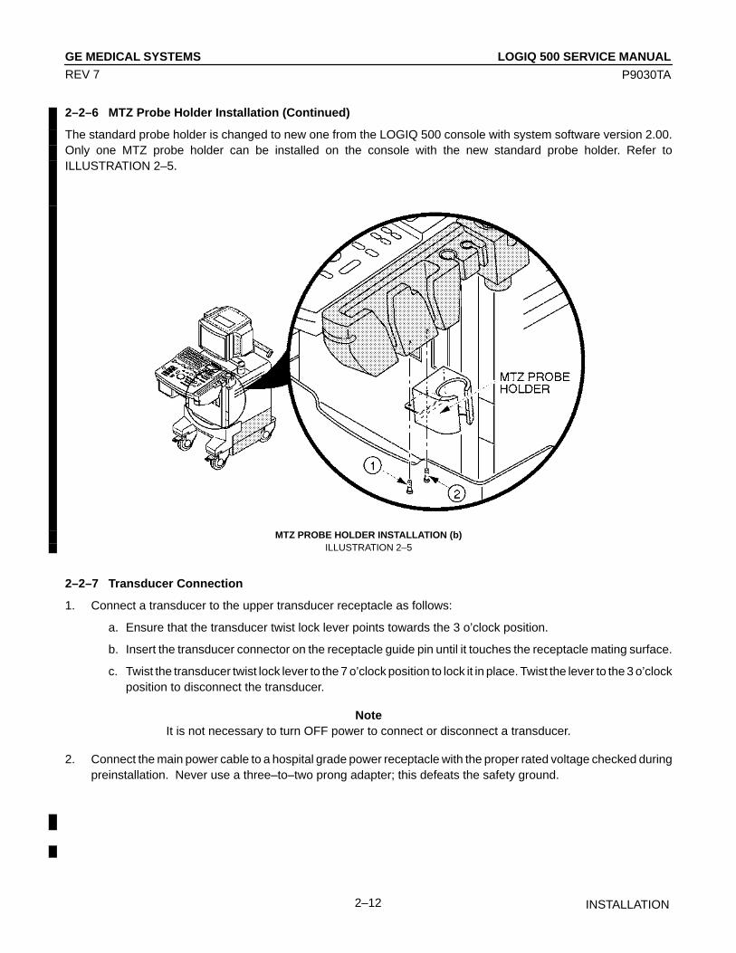
2–2–6 MTZ Probe Holder Installation (Continued)
The standard probe holder is changed to new one from the LOGIQ 500 console with system software version 2.00.Only one MTZ probe holder can be installed on the console with the new standard probe holder. Refer toILLUSTRATION 2–5.
MTZ PROBE HOLDER INSTALLATION (b)ILLUSTRATION 2–5
2–2–7 Transducer Connection
1. Connect a transducer to the upper transducer receptacle as follows:
a. Ensure that the transducer twist lock lever points towards the 3 o’clock position.
b. Insert the transducer connector on the receptacle guide pin until it touches the receptacle mating surface.
c. Twist the transducer twist lock lever to the 7 o’clock position to lock it in place. Twist the lever to the 3 o’clockposition to disconnect the transducer.
NoteIt is not necessary to turn OFF power to connect or disconnect a transducer.
2. Connect the main power cable to a hospital grade power receptacle with the proper rated voltage checked duringpreinstallation. Never use a three–to–two prong adapter; this defeats the safety ground.

LOGIQ 500 SERVICE MANUALGE MEDICAL SYSTEMS
P9030TA
INSTALLATION2–13
REV 7
2–2–8 Moving into Position
CAUTION
Do not lift the unit by the Keyboard.Do not tilt the unit more than 5 degrees to avoid tipping it over.To avoid injury by tipping over. Set the monitor to the lowest position before moving.
CAUTION
Equipment Damage Possibility. Lifting the console by holding covers may damage the cov-ers. Do not lift the console by holding any covers.
In general, a single adult can move the LOGIQ 500 along an even surface with no steep grades. At least two peopleshould move the machine when large humps, grooves, or grades will be encountered. (It is better to pull from the rearrather than push from the front of the unit). Before moving, store all loose parts in the unit. Wrap transducers in softcloth or foam to prevent damage.
Although LOGIQ 500 is a compact and mobile machine, two people should move it over rough surfaces or up and downgrades.
2–2–9 Adjusting System Clock
Set the system clock for the LOGIQ 500 to the local time. For procedure of adjusting the system clock, refer to 4–3–3Utility Menu, (A) TIME ADJUSTMENT, in Chapter 4, FUNCTIONAL CHECKS.
LOGIQ 500 SERVICE MANUALGE MEDICAL SYSTEMS
P9030TA
INSTALLATION2–14
REV 7
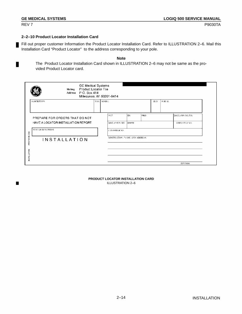
2–2–10 Product Locator Installation Card
Fill out proper customer Information the Product Locator Installation Card. Refer to ILLUSTRATION 2–6. Mail thisInstallation Card “Product Locator” to the address corresponding to your pole.
NoteThe Product Locator Installation Card shown in ILLUSTRATION 2–6 may not be same as the pro-vided Product Locator card.
PRODUCT LOCATOR INSTALLATION CARDILLUSTRATION 2–6

LOGIQ 500 SERVICE MANUALGE MEDICAL SYSTEMS
P9030TA
SYSTEM CONFIGURATION3–1
REV 14
CHAPTER 3 – SYSTEM CONFIGURATION
TABLE OF CONTENTS
SECTION TITLE PAGE
3–1 INTRODUCTION 3–3. . . . . . . . . . . . . . . . . . . . . . . . . . . . . . . . . . . . . . . . . . . . . . . . . . . . . . . . . . . . . . . . . . . . .
3–2 DIMENSIONS 3–3. . . . . . . . . . . . . . . . . . . . . . . . . . . . . . . . . . . . . . . . . . . . . . . . . . . . . . . . . . . . . . . . . . . . . . . .
3–3 ELECTRICAL SPECIFICATIONS 3–5. . . . . . . . . . . . . . . . . . . . . . . . . . . . . . . . . . . . . . . . . . . . . . . . . . . . . . . 3–3–1 Power Supply 3–5. . . . . . . . . . . . . . . . . . . . . . . . . . . . . . . . . . . . . . . . . . . . . . . . . . . . . . . . . . . . . . . 3–3–2 Facility Power Receptacle 3–5. . . . . . . . . . . . . . . . . . . . . . . . . . . . . . . . . . . . . . . . . . . . . . . . . . . . .
3–4 STORAGE AND OPERATION REQUIREMENTS 3–5. . . . . . . . . . . . . . . . . . . . . . . . . . . . . . . . . . . . . . . . .
3–5 OPTIONAL PERIPHERALS 3–6. . . . . . . . . . . . . . . . . . . . . . . . . . . . . . . . . . . . . . . . . . . . . . . . . . . . . . . . . . . . 3–5–1 Peripherals/Accessories Connector Panel 3–6. . . . . . . . . . . . . . . . . . . . . . . . . . . . . . . . . . . . . . . 3–5–2 List of Optional Peripherals 3–11. . . . . . . . . . . . . . . . . . . . . . . . . . . . . . . . . . . . . . . . . . . . . . . . . . . 3–5–3 Power Consumption of Optional Peripherals 3–17. . . . . . . . . . . . . . . . . . . . . . . . . . . . . . . . . . . .
3–6 VIDEO SPECIFICATIONS 3–18. . . . . . . . . . . . . . . . . . . . . . . . . . . . . . . . . . . . . . . . . . . . . . . . . . . . . . . . . . . .

LOGIQ 500 SERVICE MANUALGE MEDICAL SYSTEMS
P9030TA
SYSTEM CONFIGURATION3–2
REV 0
This page is left blank intentionally.

LOGIQ 500 SERVICE MANUALGE MEDICAL SYSTEMS
P9030TA
SYSTEM CONFIGURATION3–3
REV 12
3–1 INTRODUCTION
This chapter describes system configuration and specifications.
3–2 DIMENSIONS
Regarding LOGIQ 500 dimensions, Refer to ILLUSTRATION 3–1 for planning the position of your LOGIQ 500.
NoteThe weight of the console with software version 5.00y or later is approximately 192 kg (423 lbs).
NOTE LENGTH : mm (inches)ABERRATION : ±5%
WEIGHT: 180 kg 397 lbs
OVERALL DIMENSIONSILLUSTRATION 3–1
LOGIQ 500 SERVICE MANUALGE MEDICAL SYSTEMS
P9030TA
SYSTEM CONFIGURATION3–4
REV 12
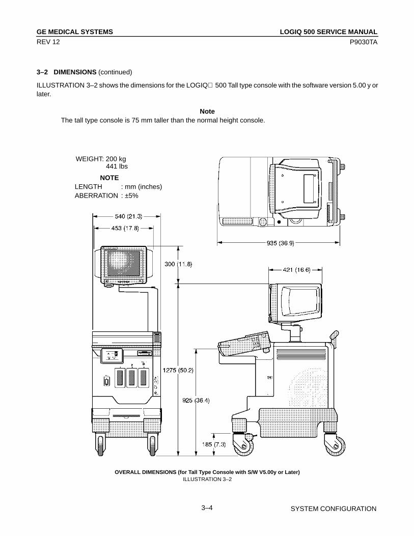
3–2 DIMENSIONS (continued)
ILLUSTRATION 3–2 shows the dimensions for the LOGIQ 500 Tall type console with the software version 5.00 y orlater.
NoteThe tall type console is 75 mm taller than the normal height console.
NOTE LENGTH : mm (inches)ABERRATION : ±5%
WEIGHT: 200 kg 441 lbs
OVERALL DIMENSIONS (for Tall Type Console with S/W V5.00y or Later)ILLUSTRATION 3–2
LOGIQ 500 SERVICE MANUALGE MEDICAL SYSTEMS
P9030TA
SYSTEM CONFIGURATION3–5
REV 12
3–3 ELECTRICAL SPECIFICATIONS
Electrical conduit, junction boxes, outlets, circuit breakers, and switches should be in place before installing the LO-GIQ 500 console.
3–3–1 Power Supply
Voltage setup is performed in the factory, since different rear panels which contain different power cables and circuitbreakers are used for the 100 VAC and 220 VAC versions.
3–3–2 Facility Power Receptacle
A separate power outlet with a 20 amp circuit breaker for 115 VAC units, or a 7.5 amp circuit breaker for 220 VAC units,is recommended. The specific power receptacle used depends on your country’s power line standards.
The receptacle should have International Electrotechnical Commission (IEC) approval, or equivalent.
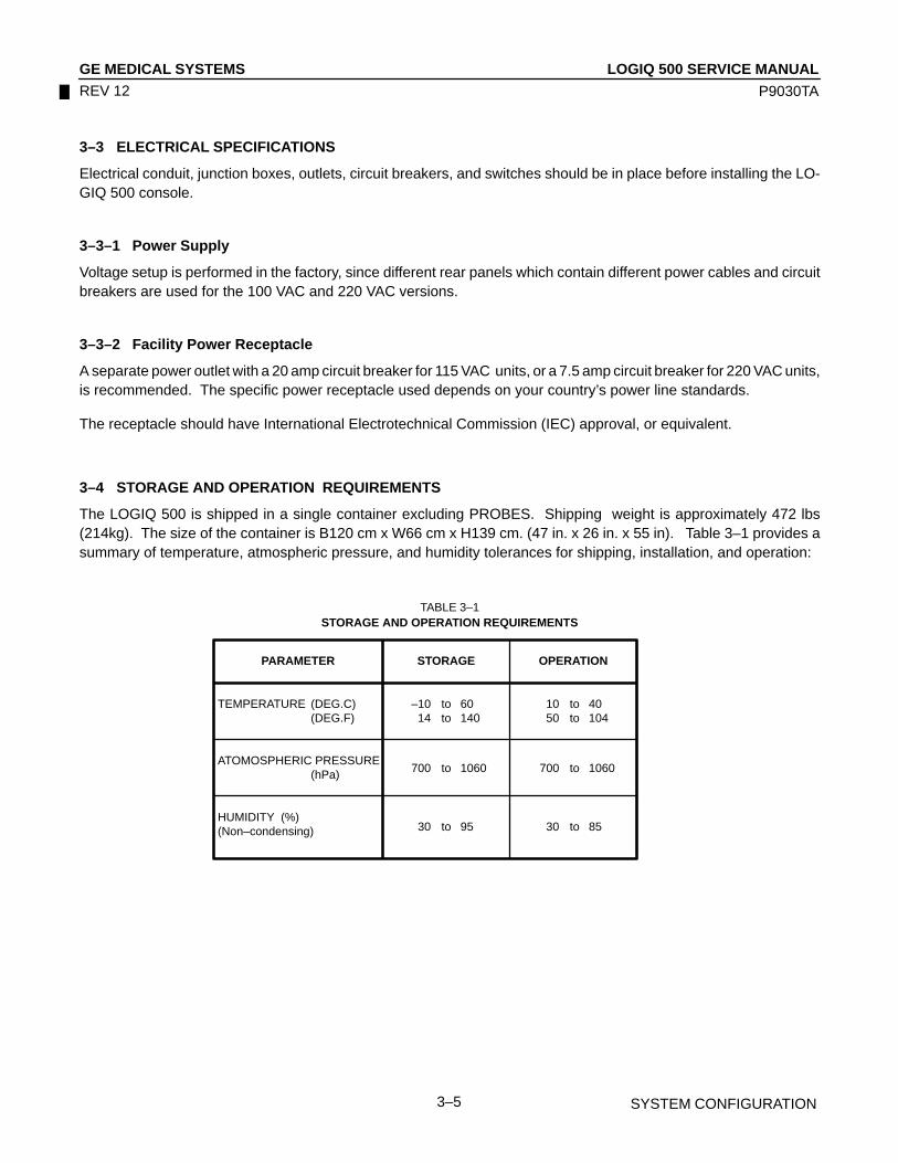
3–4 STORAGE AND OPERATION REQUIREMENTS
The LOGIQ 500 is shipped in a single container excluding PROBES. Shipping weight is approximately 472 lbs(214kg). The size of the container is B120 cm x W66 cm x H139 cm. (47 in. x 26 in. x 55 in). Table 3–1 provides asummary of temperature, atmospheric pressure, and humidity tolerances for shipping, installation, and operation:
TABLE 3–1STORAGE AND OPERATION REQUIREMENTS
PARAMETER STORAGE OPERATION
TEMPERATURE (DEG.C)(DEG.F)
ATOMOSPHERIC PRESSURE(hPa)
HUMIDITY (%)(Non–condensing)
–10 to 6014 to 140
10 to 4050 to 104
700 to 1060 700 to 1060
30 to 95 30 to 85

LOGIQ 500 SERVICE MANUALGE MEDICAL SYSTEMS
P9030TA
SYSTEM CONFIGURATION3–6
REV 12
3–5 OPTIONAL PERIPHERALS
3–5–1 Peripherals/Accessories Connector Panel
LOGIQ 500 peripherals and accessories can be properly connected using the rear connector panel located behind therear door.
Located on the panel are video input and output connectors, audio input and output, camera expose connectors, foot-switch connector power connector and control connections for VCR, printer, MIC and service tools.
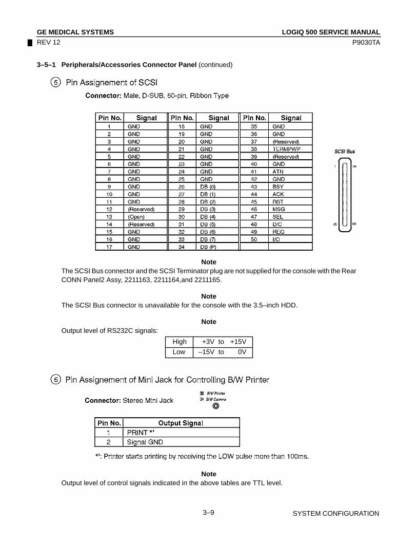
This section indicates the pin assignment for each connector ( 1 – 8 in ILLUSTRATION 3–3) at pages 3–7 through3–10.
OLD TYPE NEW TYPE
REAR CONNECTOR PANELILLUSTRATION 3–3

LOGIQ 500 SERVICE MANUALGE MEDICAL SYSTEMS
P9030TA
SYSTEM CONFIGURATION3–7
REV 12
3–5–1 Peripherals/Accessories Connector Panel (continued)
NoteThe SCSI port is not available for the console with the 3.5–inch HDD. The SCSI Terminator is notsupplied with the console with the 3.5–inch HDD.
NoteThe new Rear CONN Panel2 Assy cannot be used for the console with the 2.5–inch HDD Assy.The new Rear CONN Panel2 Assy does not have the SCSI connector.
NoteEach outer (case) ground line of peripheral/accessory connectors are protectively grounded.Signal ground lines are Not Isolated, except the Service port ( 3 ). All of signal lines (include signalGND) of the Service port are isolated.
NoteOutput level of RS232C signals:
High +3V to +15V
Low –15V to 0V

LOGIQ 500 SERVICE MANUALGE MEDICAL SYSTEMS
P9030TA
SYSTEM CONFIGURATION3–8
REV 12
3–5–1 Peripherals/Accessories Connector Panel (continued)
NoteOutput level of RS232C signals:
High +3V to +15V
Low –15V to 0V
LOGIQ 500 SERVICE MANUALGE MEDICAL SYSTEMS
P9030TA
SYSTEM CONFIGURATION3–9
REV 12
3–5–1 Peripherals/Accessories Connector Panel (continued)
NoteThe SCSI Bus connector and the SCSI Terminator plug are not supplied for the console with the RearCONN Panel2 Assy, 2211163, 2211164,and 2211165.
NoteThe SCSI Bus connector is unavailable for the console with the 3.5–inch HDD.
NoteOutput level of RS232C signals:
High +3V to +15V
Low –15V to 0V
NoteOutput level of control signals indicated in the above tables are TTL level.

LOGIQ 500 SERVICE MANUALGE MEDICAL SYSTEMS
P9030TA
SYSTEM CONFIGURATION3–10
REV 12
3–5–1 Peripherals/Accessories Connector Panel (continued)
NoteOutput level of control signals indicated in the above tables are TTL level.

LOGIQ 500 SERVICE MANUALGE MEDICAL SYSTEMS
P9030TA
SYSTEM CONFIGURATION3–11
REV 12
3–5–2 List of Optional Peripherals
The tables below shows the suggested optional peripherals for LOGIQ 500.
1. RECORDING DEVICES
TABLE 3–2LIST OF RECORDING DEVICES
DEVICE MANUFACTURER MODEL VIDEO SIGNAL
Video Cassette Recorder SONY SVO–9500MD NTSCSONY SVO–9500MDP PAL
Color Video Printer SONY UP–1800 NTSCSONY UP–3030MD NTSCSONY UP–1800EPM PALSONY UP–1850EPM PALSONY UP–2950MD NTSCSONY UP–2900MD NTSCSONY UP–2850P PALSONY UP–2800P PAL
Video Graphic Printer SONY UP870MD NTSCSONY UP890MD NTSCSONY UP860CE PALSONY UP890CE PALSONY UP890MDG NTSC / PAL
Multi Image Camera International Imaging Electronics IIE360 NTSCREPRODINE MX4 PALREPRODINE MF2 PAL
NoteSee each option installation instructions for installation and connection procedures.
NoteThe “Quad–Frm” format is available only for the following color printers:
UP–1850MD, UP–1850EPM, UP–2950MD, and UP–2850P
The “Quad–Frmls” selection for the Color Printer Memory in the SYSTEM PARAMETER SETUP, isnot available for those printers. This function is valid only for the UP–3030MD printer.

LOGIQ 500 SERVICE MANUALGE MEDICAL SYSTEMS
P9030TA
SYSTEM CONFIGURATION3–12
REV 14
3–5–2 List of Optional Peripherals (continued)
2. TRANSDUCER (PROBE)
TABLE 3–3LIST OF TRANSDUCERS
PROBE MATERIAL OF AREA OF CATALOG REQUIREDNAME HEADSHELL USING NO. ADAPTER
C364 PES ABDOMINAL CONVEX H45202CF No need
No need √
CBF PES ABDOMINAL CONVEX H46022CB PA 51
C551 PES ABDOMINAL CONVEX H45202CE No need
No need √
CAE PES ABDOMINAL CONVEX H46022CA PA 51
E721 PES INTRACAVITY CONVEX H45202MT No need
No need √
MTZ PES INTRACAVITY CONVEX H46022MT PA 51
739L NORYL SUPERFICIAL LINEAR H45202AG No need
No need √
S316 PES CARDIAC/ABDOMINAL SECTOR H45202SC No need
No need √
UC PES CARDIAC/ABDOMINAL SECTOR H4163B 5S
L764 PES SUPERFICIAL LINEAR H45202HP No need
No need √
C721 NORYL NEONATAL CONVEX H45202MN No need
No need √
LH PES SUPERFICIAL LINEAR H46022LH PA51
W PES CARDIAC SECTOR H4162C 5S
B510 PU CARDIAC H45202BT PA51
PA51 √
S220 PES CARDIAC SECTOR H45202WG No need
No need √
CWD2 NORYL CARDIAC SECTOR H45202DB No need
CWD5 NORYL CARDIAC SECTOR H45202DE No need
TYPE FAMILY PART No.PROBES
HEADSHELL IS
SAME AS CBF
HEADSHELL IS
SAME AS CAE
HEADSHELL IS
SAME AS MTZ
HEADSHELL IS
SAME AS UC
HEADSHELL IS
SAME AS LH
22592512259250
BI–PLANESECTOR
P9603ADP9603AA
22610262261025P9603AEP9603AB
22610562261055P9603AUP9603AL
22591452259144P9606ABP9606AA
P9600BEP9600BA
22592562259255
22610182261017P9601ASP9601ACP9600BHP9600BD
22592602259259
H40212LDH79082P
H40212LNH79172P
H40212LRH79192P
H40212LBH79062P
H40202LBH79222P
H40212LGH79112P
H40212LPH79182P
H40202LDH79242P
HEADSHELL IS
SAME AS CBF
HEADSHELL IS
SAME AS CAE
HEADSHELL IS
SAME AS MTZ
HEADSHELL IS
SAME AS UC
HEADSHELL IS
SAME AS LH
P9607ABP9607AA
P9607ADP9607AC
P9607AFP9607AE
2107460–22107460
22610332261032
2121377–22121377
2121267–22121267
21235932133115
WITHFERRITEBEADS
HEADSHELL IS
SAME AS W
226104322610422123594212311621235952123117
H40202LAH79212P
HEADSHELL IS
SAME AS W
2121793–22121793

LOGIQ 500 SERVICE MANUALGE MEDICAL SYSTEMS
P9030TA
SYSTEM CONFIGURATION3–13
REV 14
3–5–2 List of Optional Peripherals (continued)
2. TRANSDUCER (PROBE)
TABLE 3–3LIST OF TRANSDUCERS (continued)
PROBE MATERIAL OF AREA OF CATALOG REQUIREDNAME HEADSHELL USING NO. ADAPTER
546L NORYL LINEAR H45202LE No need
No need √
S317 NORYL CARDIAC/ABDOMINAL SECTOR H45202SD No need
No need √
S611 NORYL SECTOR H45202SF No need
No need √
C386 NORYL CONVEX H45202CC No need
No need √
I739 NORYL LINEAR H45202JG No need
No need √
T739 NORYL INTRAOPERATIVE LINEAR H45202TG No need
No need √
LA39 NORYL SUPERFICIAL LINEAR H45202LA No need
No need √
S222 NORYL TRANSCRANICAL SECTOR H45202TC No need
No need √
P509 PU CARDIAC H45202RT No need
No need √
C358 PES ABDOMINAL CONVEX H45202CD No need
No need √
LD PES BIOPSY LINEAR H45202LD PA51
PA51 √
ERB7 NORYL ENDOCAVITY H40392LC No need
No need √
3S NORYL CARDIOLOGY SECTOR No need
M12L NORYL SMALL PARTS LINEAR No need √
TYPE FAMILY PART No.PROBES
WITHFERRITEBEADS
ABDOMINAL/SUPERFICIAL
H40212LAH79052P
CARDIAC/NEONATAL/PEDIATRICS
22592382259237
ABDOMINAL/OB/GYN
22591622259160
INTRAOPERATIVE/INTRACAVITY
22592062259205
22592302259229
H40212LKH79142P
22591352259134
H40212LLH79152P
H40212LEH79092P
H40212LFH79102P
22592462259245
H40212LMH79162P
HEADSHELL IS
SAME AS 739L
22592142259213
H40212LHH79122P
22592222259221
H40212LJH79132P
MULTI–
PLANE
SECTOR 22592582259257
H40202LCH79232P
HEADSHELL IS
SAME AS 739L
2144267–22144267
2154186–22154186
2147189–22147189
2144268–22144268
2144266–22144266
2147188–22147188
2155078–22155078
21562632156263
21697732169772
CONVEXLINEAR
22591532259152
H40212LCH79072P
22610492261048
H40212LSH79202P
22592632259262
H40202LEH79252P
21936172172443
2124318P9601AD
22395902204232
22360162241735
H45282MLH75362SR
22521572261743
H4550SZH79292P

LOGIQ 500 SERVICE MANUALGE MEDICAL SYSTEMS
P9030TA
SYSTEM CONFIGURATION3–14
REV 14
3–5–2 List of Optional Peripherals (continued)
2. TRANSDUCER (PROBE) (continued)
TABLE 3–3LIST OF TRANSDUCERS (continued)
PROBE MATERIAL OF AREA OF CATALOG REQUIREDNAME HEADSHELL USING NO. ADAPTER
CS PES CONVEX PA21 √
i12L ABS INTRAOPERATIVE LINEAR PA51 √
TYPE FAMILY PART No.PROBES
WITHFERRITEBEADS
ABDOMINAL/NEONATAL
2202320
22648832270556
H45222CS
H4012LH79322P
NotePES : Polyethersulfone NORYL : Modified Polyphenylene Oxide PU : PolyurethaneABS : Acrylonitrile Butadiene Styrene
NoteSome probes indicated on the TABLE 3–3 have two different part numbers. The upper row shows thepart numbers of probes for regions other than Japan. The lower row shows the part numbers ofprobes for Japan.Probes which have only one part number are not available in Japan.
NoteL764 and C721 probes are available on consoles from software version 1.20.
NoteB510, S220, CWD2 and CWD5 probes are available on consoles from software version 2.00.
NoteB510 probe requires new PA51 probe adapter, 2136306 for Japan and 2136307 for other countries.

LOGIQ 500 SERVICE MANUALGE MEDICAL SYSTEMS
P9030TA
SYSTEM CONFIGURATION3–15
REV 14
3–5–2 List of Optional Peripherals (continued)
2. TRANSDUCER (PROBE) (continued)
Note546L, S317, S611, C386, I739 and T739 probes are available on consoles from software version2.20.
NoteLA39 and S222 probes are available on consoles from software version 3.00.
NoteTo use the LA39 probe on the console which is upgraded the software version to 3.00 from 2.20 usingthe software upgrade kit, it is also requried to install the MD Hardware Kit (2165223 for Japan and2165224 for other regions) in the console.
NoteP509 probe is available on consoles from software version 3.10. In addition, it is necessary to installthe optional Multiple TEE Upgrade Kit in the console to use the P509 probe.
NoteC358 probe is available on consoles from software version 4.00.LD probe is available for the Japanese console with software version 4.00 or later.LD probe is available for the European console with software version 4.20 or later.
NoteERB7 probe is available on consoles from software version 4.20.
NoteM12L and 3S probes are available on consoles from software version 5.00.
Note i12L probes is available on consoles from software version 6.00.
Note CS probes is available only on consoles for Asia from software version 6.00.
NoteCS probe requires PA21 probe adapter, 2277668 for Asia.
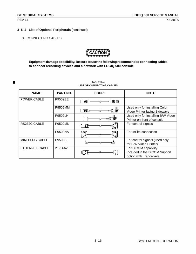
LOGIQ 500 SERVICE MANUALGE MEDICAL SYSTEMS
P9030TA
SYSTEM CONFIGURATION3–16
REV 14
3–5–2 List of Optional Peripherals (continued)
3. CONNECTING CABLES
CAUTION
Equipment damage possibility. Be sure to use the following recommended connecting cablesto connect recording devices and a network with LOGIQ 500 console.
TABLE 3–4LIST OF CONNECTING CABLES
NAME PART NO. FIGURE NOTE
POWER CABLE P9509EE
P9509MM Used only for installing ColorVideo Printer facing Sideways
P9509LH Used only for installing B/W VideoPrinter on front of console
RS232C CABLE P9509MN For control signals
P9509NA For InSite connection
MINI PLUG CABLE P9509BE For control signals (used only for B/W Video Printer)
ETHERNET CABLE 2195662 For DICOM capabilityIncluded in the DICOM Supportoption with Tranceivers

LOGIQ 500 SERVICE MANUALGE MEDICAL SYSTEMS
P9030TA
SYSTEM CONFIGURATION3–17
REV 14
3–5–3 Power Consumption of Optional Peripherals
The table below shows the power consumption of each optional peripheral for LOGIQ 500.
TABLE 3–5POWER CONSUMPTION OF OPTIONAL RECORDING DEVICES
DEVICE MODEL POWER CONSUMPTION
Video Cassette Recorder SVO–9500MD 64WSVO–9500MDP
Color Video Printer UP–3030MD 140WUP–1800UP–1850EPMUP–2950MD 220WUP–2850PUP–2900MD 180WUP–2800P
B/W Video Printer UP870MD 110WUP890MDUP860CEUP890CEUP890MDG 120W
Multi–Image Camera IIE360 60WMX4 80WMF2 380W
(at printing)
(at printing)
(at printing)
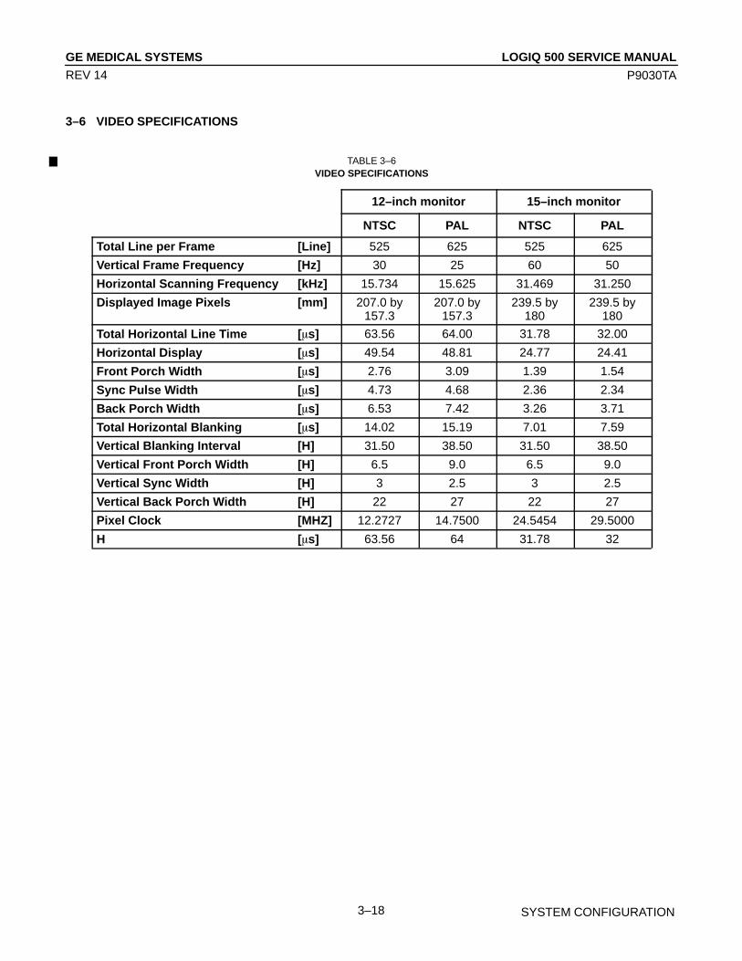
LOGIQ 500 SERVICE MANUALGE MEDICAL SYSTEMS
P9030TA
SYSTEM CONFIGURATION3–18
REV 14
3–6 VIDEO SPECIFICATIONS
TABLE 3–6VIDEO SPECIFICATIONS
12–inch monitor 15–inch monitor
NTSC PAL NTSC PAL
Total Line per Frame [Line] 525 625 525 625
Vertical Frame Frequency [Hz] 30 25 60 50
Horizontal Scanning Frequency [kHz] 15.734 15.625 31.469 31.250
Displayed Image Pixels [mm] 207.0 by157.3
207.0 by157.3
239.5 by180
239.5 by180
Total Horizontal Line Time [�s] 63.56 64.00 31.78 32.00
Horizontal Display [�s] 49.54 48.81 24.77 24.41
Front Porch Width [�s] 2.76 3.09 1.39 1.54
Sync Pulse Width [�s] 4.73 4.68 2.36 2.34
Back Porch Width [�s] 6.53 7.42 3.26 3.71
Total Horizontal Blanking [�s] 14.02 15.19 7.01 7.59
Vertical Blanking Interval [H] 31.50 38.50 31.50 38.50
Vertical Front Porch Width [H] 6.5 9.0 6.5 9.0
Vertical Sync Width [H] 3 2.5 3 2.5
Vertical Back Porch Width [H] 22 27 22 27
Pixel Clock [MHZ] 12.2727 14.7500 24.5454 29.5000
H [�s] 63.56 64 31.78 32
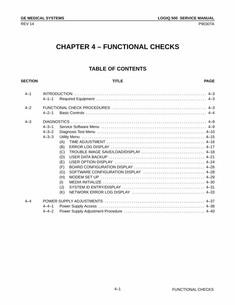
LOGIQ 500 SERVICE MANUALGE MEDICAL SYSTEMS
P9030TA
FUNCTIONAL CHECKS4–1
REV 14
CHAPTER 4 – FUNCTIONAL CHECKS
TABLE OF CONTENTS
SECTION TITLE PAGE
4–1 INTRODUCTION 4–3. . . . . . . . . . . . . . . . . . . . . . . . . . . . . . . . . . . . . . . . . . . . . . . . . . . . . . . . . . . . . . . . . . . . . 4–1–1 Required Equipment 4–3. . . . . . . . . . . . . . . . . . . . . . . . . . . . . . . . . . . . . . . . . . . . . . . . . . . . . . . . . .
4–2 FUNCTIONAL CHECK PROCEDURES 4–3. . . . . . . . . . . . . . . . . . . . . . . . . . . . . . . . . . . . . . . . . . . . . . . . . 4–2–1 Basic Controls 4–4. . . . . . . . . . . . . . . . . . . . . . . . . . . . . . . . . . . . . . . . . . . . . . . . . . . . . . . . . . . . . . .
4–3 DIAGNOSTICS 4–9. . . . . . . . . . . . . . . . . . . . . . . . . . . . . . . . . . . . . . . . . . . . . . . . . . . . . . . . . . . . . . . . . . . . . . . 4–3–1 Service Software Menu 4–9. . . . . . . . . . . . . . . . . . . . . . . . . . . . . . . . . . . . . . . . . . . . . . . . . . . . . . . 4–3–2 Diagnosis Test Menu 4–10. . . . . . . . . . . . . . . . . . . . . . . . . . . . . . . . . . . . . . . . . . . . . . . . . . . . . . . . 4–3–3 Utility Menu 4–15. . . . . . . . . . . . . . . . . . . . . . . . . . . . . . . . . . . . . . . . . . . . . . . . . . . . . . . . . . . . . . . .
(A) TIME ADJUSTMENT 4–16. . . . . . . . . . . . . . . . . . . . . . . . . . . . . . . . . . . . . . . . . . . . . . . . . . . (B) ERROR LOG DISPLAY 4–17. . . . . . . . . . . . . . . . . . . . . . . . . . . . . . . . . . . . . . . . . . . . . . . . . (C) TROUBLE IMAGE SAVE/LOAD/DISPLAY 4–18. . . . . . . . . . . . . . . . . . . . . . . . . . . . . . . . . (D) USER DATA BACKUP 4–21. . . . . . . . . . . . . . . . . . . . . . . . . . . . . . . . . . . . . . . . . . . . . . . . . . (E) USER OPTION DISPLAY 4–24. . . . . . . . . . . . . . . . . . . . . . . . . . . . . . . . . . . . . . . . . . . . . . . (F) BOARD CONFIGURATION DISPLAY 4–26. . . . . . . . . . . . . . . . . . . . . . . . . . . . . . . . . . . . . (G) SOFTWARE CONFIGURATION DISPLAY 4–28. . . . . . . . . . . . . . . . . . . . . . . . . . . . . . . . (H) MODEM SET UP 4–29. . . . . . . . . . . . . . . . . . . . . . . . . . . . . . . . . . . . . . . . . . . . . . . . . . . . . . (I) MEDIA INITIALIZE 4–30. . . . . . . . . . . . . . . . . . . . . . . . . . . . . . . . . . . . . . . . . . . . . . . . . . . . . (J) SYSTEM ID ENTRY/DISPLAY 4–31. . . . . . . . . . . . . . . . . . . . . . . . . . . . . . . . . . . . . . . . . . . (K) NETWORK ERROR LOG DISPLAY 4–33. . . . . . . . . . . . . . . . . . . . . . . . . . . . . . . . . . . . . .
4–4 POWER SUPPLY ADJUSTMENTS 4–37. . . . . . . . . . . . . . . . . . . . . . . . . . . . . . . . . . . . . . . . . . . . . . . . . . . . 4–4–1 Power Supply Access 4–38. . . . . . . . . . . . . . . . . . . . . . . . . . . . . . . . . . . . . . . . . . . . . . . . . . . . . . . 4–4–2 Power Supply Adjustment Procedure 4–40. . . . . . . . . . . . . . . . . . . . . . . . . . . . . . . . . . . . . . . . . .

LOGIQ 500 SERVICE MANUALGE MEDICAL SYSTEMS
P9030TA
FUNCTIONAL CHECKS4–2
REV 0
This page is left blank intentionally.

LOGIQ 500 SERVICE MANUALGE MEDICAL SYSTEMS
P9030TA
FUNCTIONAL CHECKS4–3
REV 0
4–1 INTRODUCTION
This chapter provides procedures for quickly checking major functions of the LOGIQ 500 console, diagnostics by usingthe built–in service software, and power supply adjustments.
4–1–1 Required Equipment
To perform these tests, you’ll need any of a sector, linear, or a convex transducer.
4–2 FUNCTIONAL CHECK PROCEDURES
Note•LOGIQ 500 has new key–display function. While turning the power switch ON, three situations ofillumination should be displayed on the keyboard. These means as follows:
Bright or fully illuminated Keys; are ACTIVE or CANCELABLE selections.Dim or half illuminated Keys; are ENABLED or AVAILABLE selections.OFF or Keys that are not illuminated; are DISABLED or UNAVAILABLE selections.
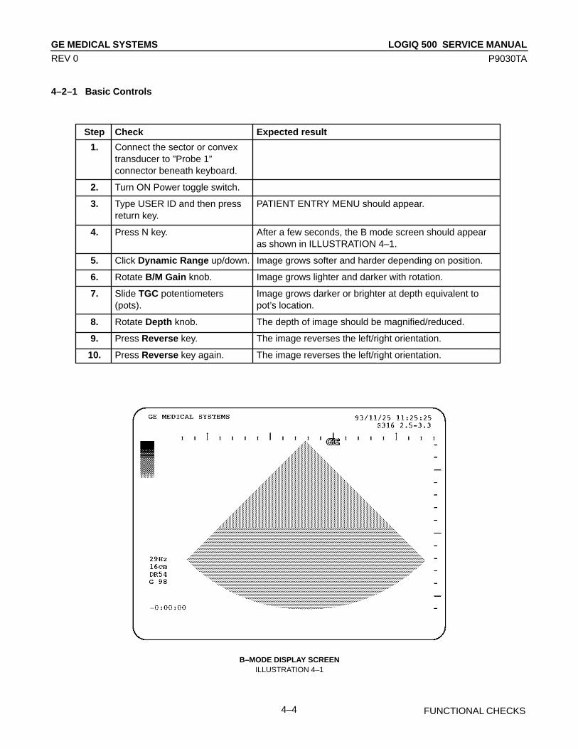
LOGIQ 500 SERVICE MANUALGE MEDICAL SYSTEMS
P9030TA
FUNCTIONAL CHECKS4–4
REV 0
4–2–1 Basic Controls
Step Check Expected result
1. Connect the sector or convextransducer to ”Probe 1”connector beneath keyboard.
2. Turn ON Power toggle switch.
3. Type USER ID and then press PATIENT ENTRY MENU should appear.return key.
4. Press N key. After a few seconds, the B mode screen should appearas shown in ILLUSTRATION 4–1.
5. Click Dynamic Range up/down. Image grows softer and harder depending on position.
6. Rotate B/M Gain knob. Image grows lighter and darker with rotation.
7. Slide TGC potentiometers Image grows darker or brighter at depth equivalent to(pots). pot’s location.
8. Rotate Depth knob. The depth of image should be magnified/reduced.
9. Press Reverse key. The image reverses the left/right orientation.
10. Press Reverse key again. The image reverses the left/right orientation.
B–MODE DISPLAY SCREENILLUSTRATION 4–1

LOGIQ 500 SERVICE MANUALGE MEDICAL SYSTEMS
P9030TA
FUNCTIONAL CHECKS4–5
REV 5
4–2–1 Basic Controls (Continued)
Step Check Expected result
11. Press M key. The M mode timeline should appear below the B imageas shown in ILLUSTRATION 4–2. Whether it takes halfthe screen or two–thirds depends on the preset.
12. Roll trackball. The Mode cursor should follow trackball movement andthe timeline should update for new location of focus.
13. Press Scan Area button. The M mode cursor should be inactive. The scan areaframe should appear. The scan area frame grows wideror narrower depending on trackball movement.
14. Press M/D Cursor button. The M mode cursor should be active again.
15. Click paddle under the 2nd Changes the M image.softkey choice to adjust MEdge Enhancement up/down.
M–MODE DISPLAY SCREENILLUSTRATION 4–2
NoteYou can select several types of display format by using the Preset Menu. For the Preset Menu, refer toCustomizing Your System in the LOGIQ 500 User Manual.
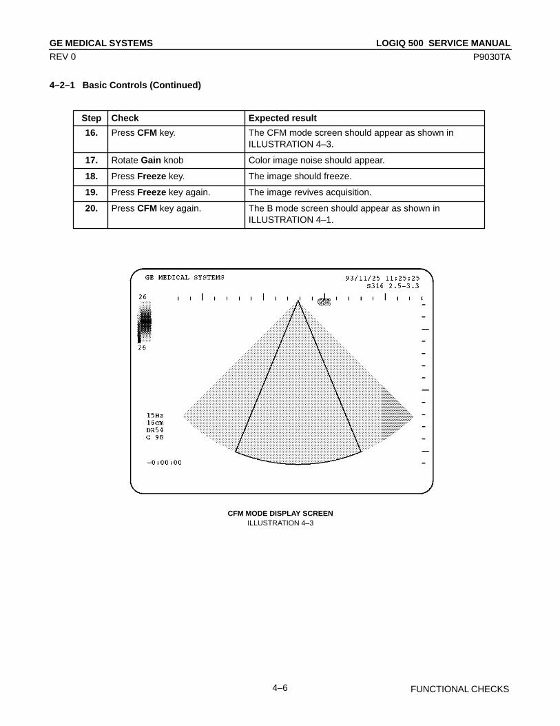
LOGIQ 500 SERVICE MANUALGE MEDICAL SYSTEMS
P9030TA
FUNCTIONAL CHECKS4–6
REV 0
4–2–1 Basic Controls (Continued)
Step Check Expected result
16. Press CFM key. The CFM mode screen should appear as shown inILLUSTRATION 4–3.
17. Rotate Gain knob Color image noise should appear.
18. Press Freeze key. The image should freeze.
19. Press Freeze key again. The image revives acquisition.
20. Press CFM key again. The B mode screen should appear as shown in ILLUSTRATION 4–1.
CFM MODE DISPLAY SCREENILLUSTRATION 4–3

LOGIQ 500 SERVICE MANUALGE MEDICAL SYSTEMS
P9030TA
FUNCTIONAL CHECKS4–7
REV 0
4–2–1 Basic Controls (Continued)
Step Check Expected result
21. Press PD key twice. The Pulse Doppler mode screen should appear as shownin ILLUSTRATION 4–4.
22. Rotate Angle knob. A line should appear in the box on the B mode image andthat line should rotate.
23. Rotate Gain knob. The Doppler noise should increase/decrease.
24. Rotate Audio Volume knob. The Doppler audio volume should increase/decrease.
25. Press B key. The B mode screen should appear as shown inILLUSTRATION 4–1.
26. Click Acoustic Output up/down. The upper portion of the image grows lighter or darkerdepending on position
PULSE DOPPLER MODE DISPLAY SCREENILLUSTRATION 4–4
NoteYou can select the two types of display format: Side by Side (with the 2–D display to the left of thePD–mode display) and Top/Bottom (with the 2–D display on top of the PD–mode display) by using thePreset Menu. For the Preset Menu, refer to Customizing Your System in the LOGIQ 500 User Manual.
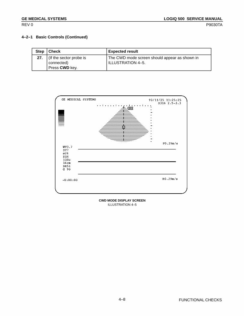
LOGIQ 500 SERVICE MANUALGE MEDICAL SYSTEMS
P9030TA
FUNCTIONAL CHECKS4–8
REV 0
4–2–1 Basic Controls (Continued)
Step Check Expected result
27. (If the sector probe is The CWD mode screen should appear as shown inconnected) ILLUSTRATION 4–5.Press CWD key.
CWD MODE DISPLAY SCREENILLUSTRATION 4–5
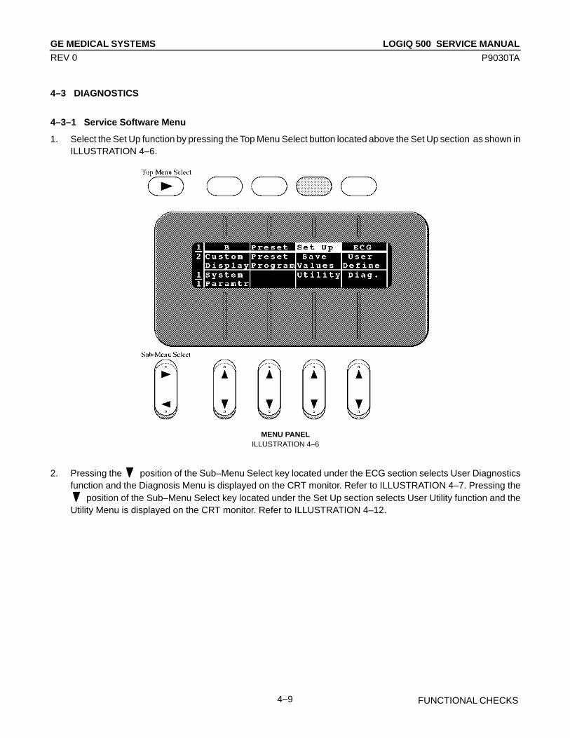
LOGIQ 500 SERVICE MANUALGE MEDICAL SYSTEMS
P9030TA
FUNCTIONAL CHECKS4–9
REV 0
4–3 DIAGNOSTICS
4–3–1 Service Software Menu
1. Select the Set Up function by pressing the Top Menu Select button located above the Set Up section as shown inILLUSTRATION 4–6.
MENU PANELILLUSTRATION 4–6
2. Pressing the position of the Sub–Menu Select key located under the ECG section selects User Diagnosticsfunction and the Diagnosis Menu is displayed on the CRT monitor. Refer to ILLUSTRATION 4–7. Pressing the
position of the Sub–Menu Select key located under the Set Up section selects User Utility function and theUtility Menu is displayed on the CRT monitor. Refer to ILLUSTRATION 4–12.
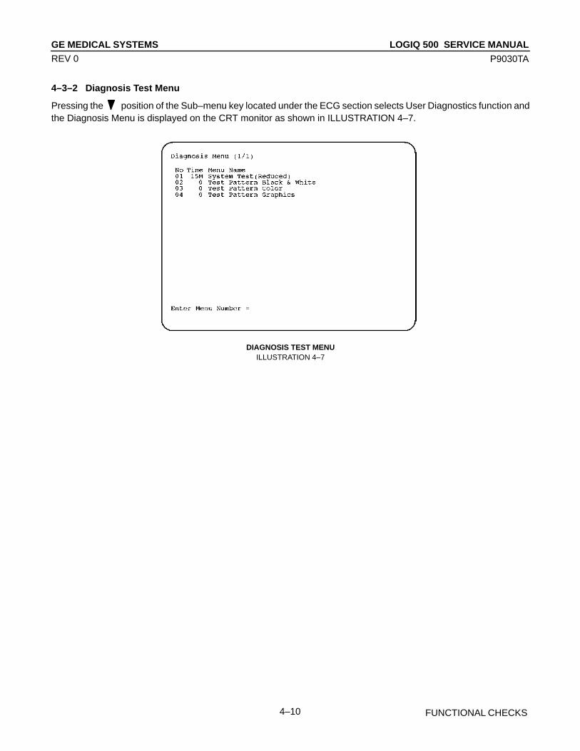
LOGIQ 500 SERVICE MANUALGE MEDICAL SYSTEMS
P9030TA
FUNCTIONAL CHECKS4–10
REV 0
4–3–2 Diagnosis Test Menu
Pressing the position of the Sub–menu key located under the ECG section selects User Diagnostics function andthe Diagnosis Menu is displayed on the CRT monitor as shown in ILLUSTRATION 4–7.
DIAGNOSIS TEST MENUILLUSTRATION 4–7

LOGIQ 500 SERVICE MANUALGE MEDICAL SYSTEMS
P9030TA
FUNCTIONAL CHECKS4–11
REV 8
4–3–2 Diagnosis Test Menu (Continued)
(A) SYSTEM TEST 1
Be sure to connect any probes with the unit to check the following system test.Type 1 and then press Enter key when the Diagnosis Menu is displayed. The system test will start automatically.After checking each test item, “PASSED” or “FAILED” is displayed depending on the actual test result.
SYSTEM TEST 1ILLUSTRATION 4–8
NoteFor the software version 3.00 or later, “ACFP” or “COLP” is indicated on the CRT monitor screen de-pending on the type of board assy currently installed in the console when the Color Flow Test 2, Item12, is completed.
The system beeps three times after checking all the tests.
If system did not pass the diagnostic test, please contact the qualified service engineer in your area. Please referto page 1–18 to for the appropriate address/phone number to contact service.

LOGIQ 500 SERVICE MANUALGE MEDICAL SYSTEMS
P9030TA
FUNCTIONAL CHECKS4–12
REV 0
4–3–2 Diagnosis Test Menu (Continued)
(B) TEST PATTERN BLACK & WHITE
The black & white pattern permits the serviceman to accurately adjust the contrast of an optional equipment(such as a camera) to see the details in the lightest and darkest areas of the image.
Type 2 and then press Enter key when the Diagnosis Menu is displayed. The Test Pattern Black & White is dis-played as shown in ILLUSTRATION 4–9.
TEST PATTERN BLACK & WHITEILLUSTRATION 4–9

LOGIQ 500 SERVICE MANUALGE MEDICAL SYSTEMS
P9030TA
FUNCTIONAL CHECKS4–13
REV 0
4–3–2 Diagnosis Test Menu (Continued)
(C) TEST PATTERN COLOR
The color scale permits the serviceman to adjust the color contrast of an optional equipment (such as a colorvideo printer).
Type 3 and then press Enter key when the Diagnosis Menu is displayed. The Test Pattern Color is displayed asshown in ILLUSTRATION 4–10.
TEST PATTERN COLORILLUSTRATION 4–10
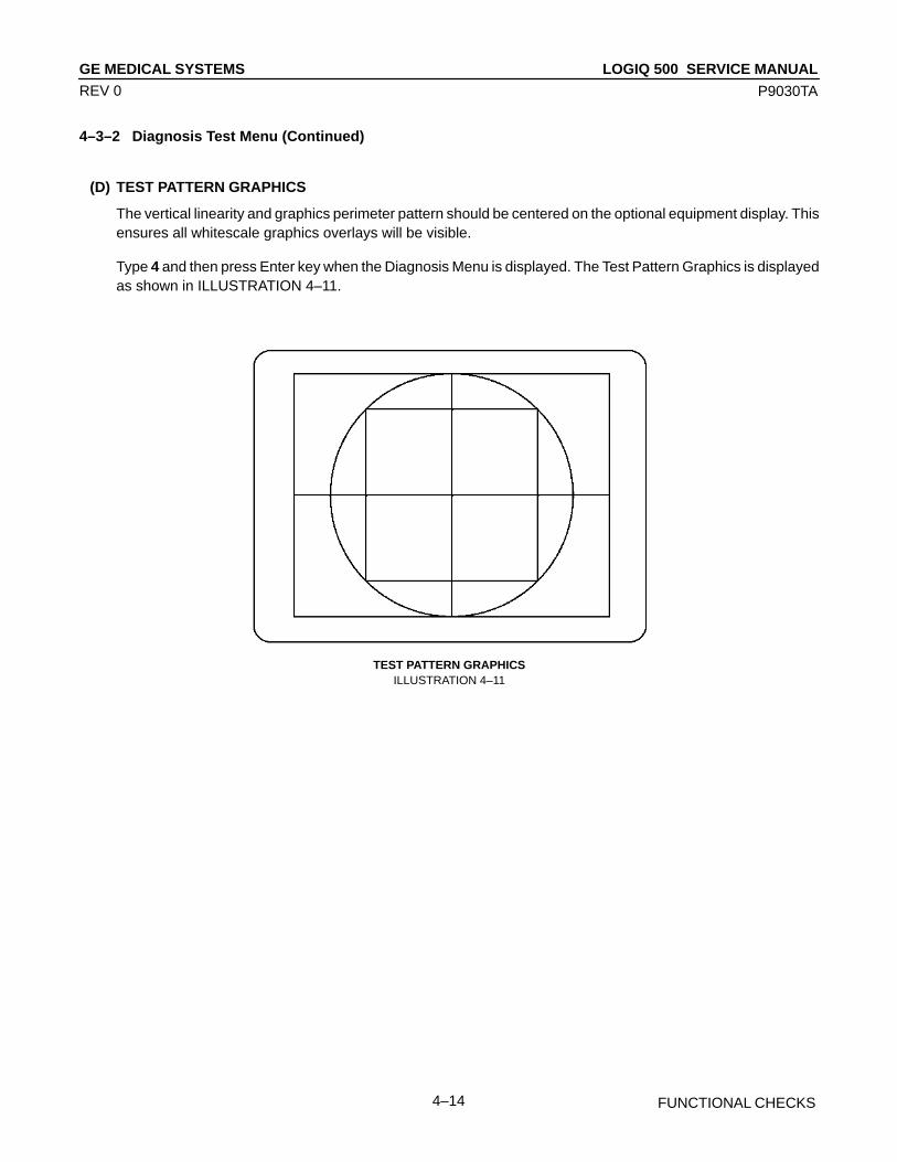
LOGIQ 500 SERVICE MANUALGE MEDICAL SYSTEMS
P9030TA
FUNCTIONAL CHECKS4–14
REV 0
4–3–2 Diagnosis Test Menu (Continued)
(D) TEST PATTERN GRAPHICS
The vertical linearity and graphics perimeter pattern should be centered on the optional equipment display. Thisensures all whitescale graphics overlays will be visible.
Type 4 and then press Enter key when the Diagnosis Menu is displayed. The Test Pattern Graphics is displayedas shown in ILLUSTRATION 4–11.
TEST PATTERN GRAPHICSILLUSTRATION 4–11
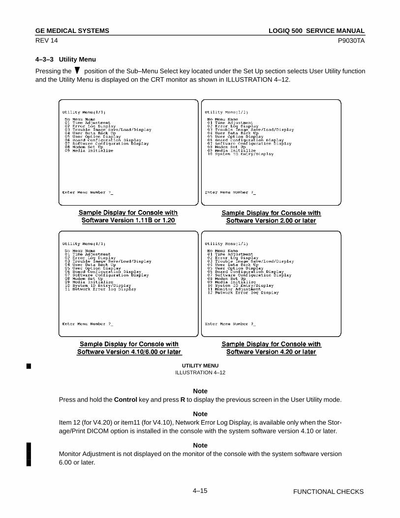
LOGIQ 500 SERVICE MANUALGE MEDICAL SYSTEMS
P9030TA
FUNCTIONAL CHECKS4–15
REV 14
4–3–3 Utility Menu
Pressing the position of the Sub–Menu Select key located under the Set Up section selects User Utility functionand the Utility Menu is displayed on the CRT monitor as shown in ILLUSTRATION 4–12.
UTILITY MENUILLUSTRATION 4–12
NotePress and hold the Control key and press R to display the previous screen in the User Utility mode.
NoteItem 12 (for V4.20) or item11 (for V4.10), Network Error Log Display, is available only when the Stor-age/Print DICOM option is installed in the console with the system software version 4.10 or later.
NoteMonitor Adjustment is not displayed on the monitor of the console with the system software version6.00 or later.
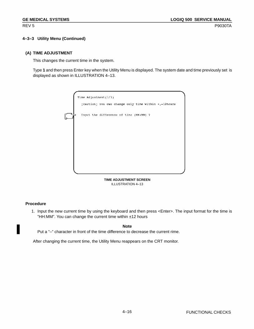
LOGIQ 500 SERVICE MANUALGE MEDICAL SYSTEMS
P9030TA
FUNCTIONAL CHECKS4–16
REV 5
4–3–3 Utility Menu (Continued)
(A) TIME ADJUSTMENT
This changes the current time in the system.
Type 1 and then press Enter key when the Utility Menu is displayed. The system date and time previously set isdisplayed as shown in ILLUSTRATION 4–13.
TIME ADJUSTMENT SCREENILLUSTRATION 4–13
Procedure
1. Input the new current time by using the keyboard and then press <Enter>. The input format for the time is”HH:MM”. You can change the current time within ±12 hours
NotePut a ”–” character in front of the time difference to decrease the current rime.
After changing the current time, the Utility Menu reappears on the CRT monitor.

LOGIQ 500 SERVICE MANUALGE MEDICAL SYSTEMS
P9030TA
FUNCTIONAL CHECKS4–17
REV 10
4–3–3 Utility Menu (Continued)
(B) ERROR LOG DISPLAY
This loads and displays an error log file, or saves it into a Floppy disk for the console with software version 1.20 orformer or into a MO disk for the console with software version 2.00 or later.
Type 2 and then press Return key when the Utility Menu is displayed. The Error Log Display is displayed asshown in ILLUSTRATION 4–14.
ERROR LOG FILE DISPLAYILLUSTRATION 4–14
Procedure for Saving File
1. Type Y and then press Return key.
2. Insert a floppy disk into the FD drive and press any key in the case of system software version 1.20 or formerconsole.Insert an 128MB MO (Magneto Optical) disk into the MOD drive and press any key in the case of system soft-ware version 2.00 or later console.
NoteThe 230MB MO disk is available on the console with software version 3.10 or later.
During the time that the system is saving the error log file, “Copying now” is displayed on the CRT monitor.

LOGIQ 500 SERVICE MANUALGE MEDICAL SYSTEMS
P9030TA
FUNCTIONAL CHECKS4–18
REV 7
4–3–3 Utility Menu (Continued)
(C) TROUBLE IMAGE SAVE/LOAD/DISPLAY
This saves the trouble image recorded in the Hard Disk into a Floppy or MO (Magneto Optical) Disk. This alsoloads the image data saved in the Floppy or MO Disk into the Hard Disk and displays the selected trouble imageon the CRT monitor by using the image recall function.
NotePress and hold the Control key and press W to save the trouble image recorded in the VCR PlaybackMemory into the hard disk. You can save the maximum 4 images into the hard disk of the system soft-ware version 1.20 or former console. The system software version 2.00 or later console can save themaximum 8 images.
Type 3 and then press Return key when the Utility Menu is displayed. The following screen is displayed.
TROUBLE IMAGE SAVE/LOAD/DISPLAYILLUSTRATION 4–15
LOGIQ 500 SERVICE MANUALGE MEDICAL SYSTEMS
P9030TA
FUNCTIONAL CHECKS4–19
REV 10
4–3–3 Utility Menu (Continued)
(C) TROUBLE IMAGE SAVE/LOAD/DISPLAY (Continued)
Procedure for Saving Trouble Images
1. Type 1 and then press Return key. The message “Set a media to drive and then press any key.” is displayed.
2. Set a floppy disk into the FD drive and press any key in the case of system software version 1.20 or formerconsole.Set an 128MB MO (Magneto Optical) disk into the MOD drive and press any key in the case of system softwareversion 2.00 or later console.The Trouble Image File Menu will be displayed. Refer to ILLUSTRATION 4–15.
NoteThe 230MB MO disk is available on the console with software version 3.10 or later.
3. Input the menu number you desire to save into the disk.
4. Press Return key.
During the system is saving the file, “Saving now” is displayed on the CRT monitor. After saving the file,“Succeeded” or “Failed” is displayed on the CRT monitor. Then, “Press Y to continue, Control + R to quit” is dis-played. Type Y and press Enter to continue to use this function. Press and hold Control, and press R to quit thisfunction.
Procedure for Loading Trouble Image
1. Type 2 and then press Return key. The message “Set a media to drive and then press any key.” is displayed.
2. Set the floppy disk storing the previous trouble images into the FD drive and press any key in the case of sys-tem software version 1.20 or former console.Set the 128MB MO (Magneto Optical) disk storing the previous trouble images into the MOD drive and pressany key in the case of system software version 2.00 or later console.The Trouble Image File Menu will be displayed. Refer to ILLUSTRATION 4–15.
NoteThe 230MB MO disk is available on the console with software version 3.10 or later.
3. Input the menu number you desire to load from the floppy or MO disk.
4. Press Return key.
During the system is loading the file, “Loading now” is displayed on the CRT monitor. After loading the file,“Succeeded” or “Failed” is displayed on the CRT monitor. Then, “Press Y to continue, Control + R to quit” is dis-played. Type Y and press Enter to continue to use this function. Press and hold Control, and press R to quit thisfunction.

LOGIQ 500 SERVICE MANUALGE MEDICAL SYSTEMS
P9030TA
FUNCTIONAL CHECKS4–20
REV 10
4–3–3 Utility Menu (Continued)
(C) TROUBLE IMAGE SAVE/LOAD/DISPLAY (Continued)
Procedure for Displaying Trouble Image
1. Type 3 and then press Return key. The Trouble Image File Menu will be displayed. Refer toILLUSTRATION 4–15.
2. Input the menu number you desire to display on the CRT monitor.
3. Press Return key.
Press and hold Control key and press Q to display the Trouble Image Menu on the CRT monitor again.

LOGIQ 500 SERVICE MANUALGE MEDICAL SYSTEMS
P9030TA
FUNCTIONAL CHECKS4–21
REV 10
4–3–3 Utility Menu (Continued)
(D) USER DATA BACK UP
This saves the user preset data into the external recording media. This also loads the user preset data stored inexternal recording media to the hard disk.The software version 2.00 or later console with the MOD drive can save and load all user preset data using oneinitialized disk. The software version 1.20 or former console with FD drive requires some floppy disks as same asthe number of categories.
NoteThe user preset data is different depending on each category and is saved into a floppy disk by eachcategory. The user preset data is divided as follows:
System DataApplication (Rad/Abdomen) DataApplication (Obstetrics) DataApplication (Gynecology) DataApplication (Cardiology) DataApplication (Vascular) DataApplication (Urology) DataApplication (Small Parts) Data
System data includes:
System preset data file, User define data file*, VCR registration information data file*,VCR patient information data file*, and Image archive search data file*
Each application data includes:
Application Preset Data file, Probe Preset Data file, Report Format Data file,OB Table Data file, Fetal trend patient data file*, and Cardiac calc auto sequence data file*
The files with the symbol “*” listed above are saved only when the optional software is installed andany files are stored in the hard disk.
The software version 1.20 or former console can save and load only the following files among the fileslisted above:
System preset data file,Application Preset Data file, Probe Preset Data file, Report Format Data file,and OB Table Data file
NoteThe console with software version 2.00 or later can save the all system data and application data intoa MO disk.
NoteThe 230MB MO disk is available on the console with software version 3.10 or later.
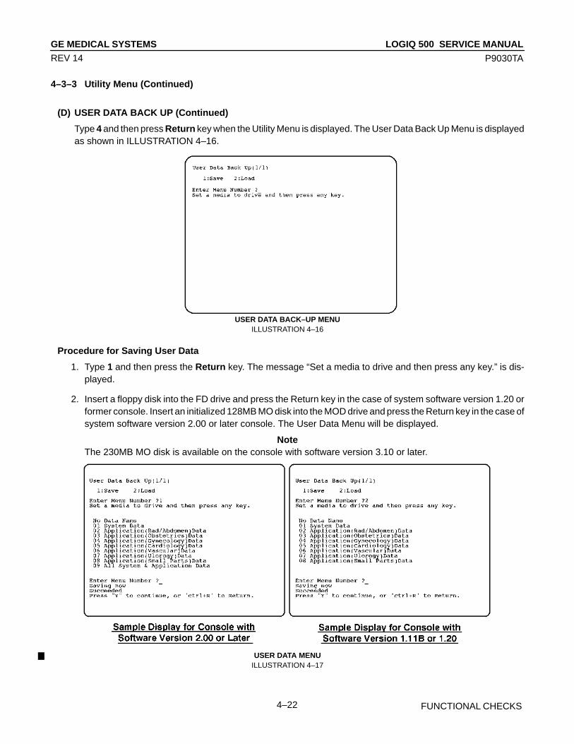
LOGIQ 500 SERVICE MANUALGE MEDICAL SYSTEMS
P9030TA
FUNCTIONAL CHECKS4–22
REV 14
4–3–3 Utility Menu (Continued)
(D) USER DATA BACK UP (Continued)
Type 4 and then press Return key when the Utility Menu is displayed. The User Data Back Up Menu is displayedas shown in ILLUSTRATION 4–16.
USER DATA BACK–UP MENUILLUSTRATION 4–16
Procedure for Saving User Data
1. Type 1 and then press the Return key. The message “Set a media to drive and then press any key.” is dis-played.
2. Insert a floppy disk into the FD drive and press the Return key in the case of system software version 1.20 orformer console. Insert an initialized 128MB MO disk into the MOD drive and press the Return key in the case ofsystem software version 2.00 or later console. The User Data Menu will be displayed.
NoteThe 230MB MO disk is available on the console with software version 3.10 or later.
USER DATA MENUILLUSTRATION 4–17
LOGIQ 500 SERVICE MANUALGE MEDICAL SYSTEMS
P9030TA
FUNCTIONAL CHECKS4–23
REV 10
4–3–3 Utility Menu (Continued)
(D) USER DATA BACK UP (Continued)
3. Input the menu number you desire to save into the disk.
NoteThe system software version 2.00 or later console can save all user data using one MO disk. Type 9and then press Return key to save all user data into a MO disk.
4. Press the Return key. The system starts saving.
During the system is saving the file, “Saving now” is displayed on the CRT monitor. After saving the file,“Succeeded” or “Failed” is displayed on the CRT monitor. Then, “Press Y to continue, Control + R to quit” is dis-played. Type Y and press Enter to continue to use this function. Press and hold Control, and press R to quit thisfunction.
Type S and then press Return key to save the User Data. Type L and then press Return key to load the UserData.
Procedure for Loading User Data
1. Type 2 and then press the Return key. The message “Set a media to drive and then press any key.” is dis-played.
2. Insert a floppy disk into the FD drive and press the Return key in the case of system software version 1.20 orformer console.Insert a 128MB MO disk into the MOD drive and press the Return key in the case of system software version2.00 or later console.The User Data Menu will be displayed. Refer to ILLUSTRATION 4–17.
NoteThe 230MB MO disk is available on the console with software version 3.10 or later.
3. Input the menu number you desire to load from the disk.
NoteThe system software version 2.00 or later console can load all user data using one MO disk. Type 9and then press Return key to load all user data stored in the MO disk to the hard disk.
4. Press Return key. The system starts loading.
During the system is saving the file, “Loading now” is displayed on the CRT monitor. After saving the file,“Succeeded” or “Failed” is displayed on the CRT monitor. Then, “Press Y to continue, Control + R to quit” is dis-played. Type Y and press Enter to continue to use this function. Press and hold Control, and press R to quit thisfunction.
NoteAfter loading the User Data, turn the system power OFF. Turn the system power ON again after com-pleting the power off process.
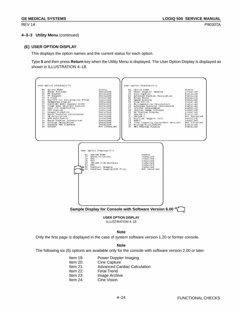
LOGIQ 500 SERVICE MANUALGE MEDICAL SYSTEMS
P9030TA
FUNCTIONAL CHECKS4–24
REV 14
4–3–3 Utility Menu (continued)
(E) USER OPTION DISPLAY
This displays the option names and the current status for each option.
Type 5 and then press Return key when the Utility Menu is displayed. The User Option Display is displayed asshown in ILLUSTRATION 4–18.
Sample Display for Console with Software Version 6.00
USER OPTION DISPLAYILLUSTRATION 4–18
NoteOnly the first page is displayed in the case of system software version 1.20 or former console.
NoteThe following six (6) options are available only for the console with software version 2.00 or later.
Item 19: Power Doppler ImagingItem 20: Cine CaptureItem 21: Advanced Cardiac CalculationItem 22: Fetal TrendItem 23: Image ArchiveItem 24: Cine Vision
LOGIQ 500 SERVICE MANUALGE MEDICAL SYSTEMS
P9030TA
FUNCTIONAL CHECKS4–25
REV 11
4–3–3 Utility Menu (continued)
(E) USER OPTION DISPLAY (continued)
NoteThe following five (5) options are available only for the console with software version 3.00 or later.
Item 25: Multigestation CalculationItem 26: Advanced Vascular CalculationItem 27: CFM/PDI EnhancementItem 28: Digital Image SoftenerItem 29: MD Startup Display
NoteThe following option is available only for the console with software version 3.10 or later.
Item 30: 3D Imaging
NoteThe following seven (7) options are available only for the console with software version 4.00 or later.
Item 30: 3DvieW–1Item 31: 3DvieW–2Item 32: Real Time Doppler CalculationItem 33: ACE–2Item 34: Time Intensity Curve (Test Version)Item 35: DICOMItem 36: MR3 Startup Display
NoteThe following option is available only for the console with software version 4.10 or later.
Item 37: Worklist(DICOM)
NoteThe name of item 30, “3D Imaging” on the software version 3.10 is changed to “3DvieW–1” from thesoftware version 4.00.
NoteThe item 35, “DICOM” on the software version 4.00 is renamed to “Storage/Print(DICOM” from thesoftware version 4.10.
NoteThe item 31, “3DvieW–2” is NOT available on the console with the software version 4.00 and 4.10.
NoteThis function can only display the option names. It is not possible for the user to change the optionsettings.
NotePress and hold the Control key and press F to go to next page. Press and hold the Control key andpress B to go to previous page.
NoteThe status of options indicated on the user option display is different depending on the system config-uration.
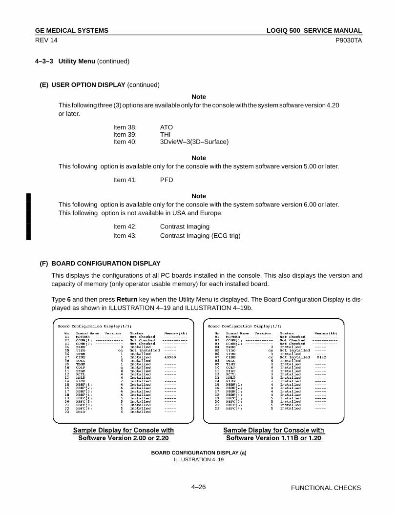
LOGIQ 500 SERVICE MANUALGE MEDICAL SYSTEMS
P9030TA
FUNCTIONAL CHECKS4–26
REV 14
4–3–3 Utility Menu (continued)
(E) USER OPTION DISPLAY (continued)
NoteThis following three (3) options are available only for the console with the system software version 4.20or later.
Item 38: ATOItem 39: THIItem 40: 3DvieW–3(3D–Surface)
NoteThis following option is available only for the console with the system software version 5.00 or later.
Item 41: PFD
NoteThis following option is available only for the console with the system software version 6.00 or later.This following option is not available in USA and Europe.
Item 42: Contrast ImagingItem 43: Contrast Imaging (ECG trig)
(F) BOARD CONFIGURATION DISPLAY
This displays the configurations of all PC boards installed in the console. This also displays the version andcapacity of memory (only operator usable memory) for each installed board.
Type 6 and then press Return key when the Utility Menu is displayed. The Board Configuration Display is dis-played as shown in ILLUSTRATION 4–19 and ILLUSTRATION 4–19b.
BOARD CONFIGURATION DISPLAY (a)ILLUSTRATION 4–19
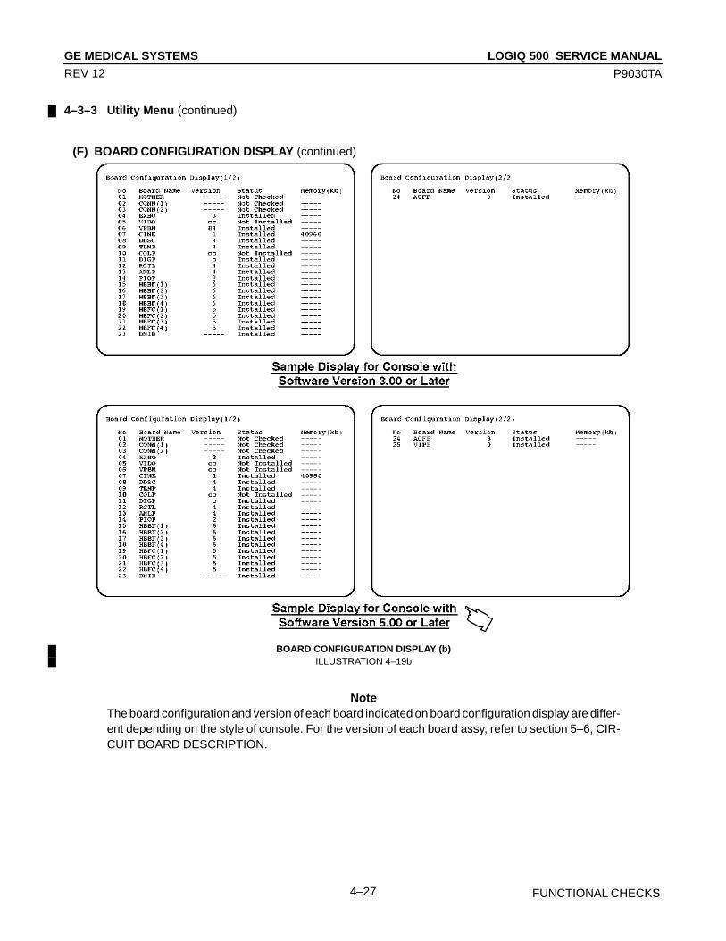
LOGIQ 500 SERVICE MANUALGE MEDICAL SYSTEMS
P9030TA
FUNCTIONAL CHECKS4–27
REV 12
4–3–3 Utility Menu (continued)
(F) BOARD CONFIGURATION DISPLAY (continued)
BOARD CONFIGURATION DISPLAY (b)ILLUSTRATION 4–19b
NoteThe board configuration and version of each board indicated on board configuration display are differ-ent depending on the style of console. For the version of each board assy, refer to section 5–6, CIR-CUIT BOARD DESCRIPTION.
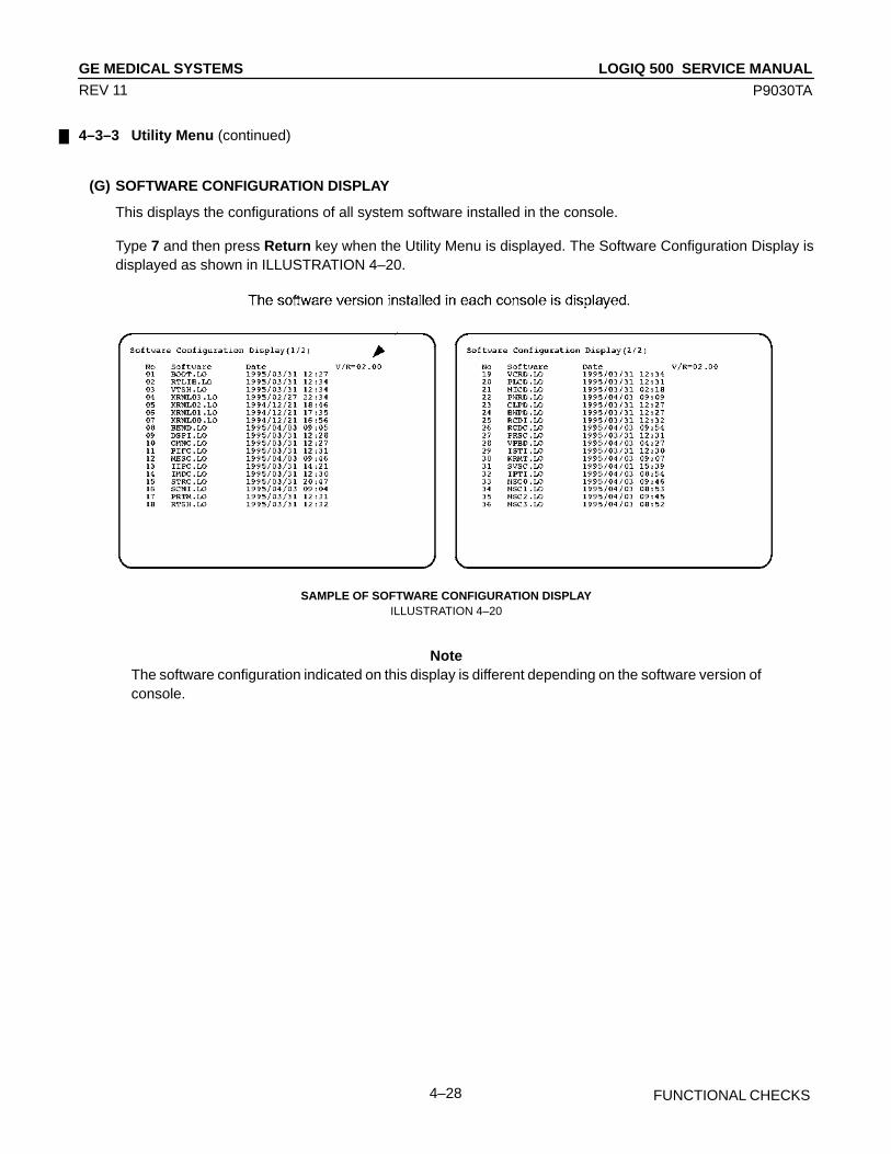
LOGIQ 500 SERVICE MANUALGE MEDICAL SYSTEMS
P9030TA
FUNCTIONAL CHECKS4–28
REV 11
4–3–3 Utility Menu (continued)
(G) SOFTWARE CONFIGURATION DISPLAY
This displays the configurations of all system software installed in the console.
Type 7 and then press Return key when the Utility Menu is displayed. The Software Configuration Display isdisplayed as shown in ILLUSTRATION 4–20.
SAMPLE OF SOFTWARE CONFIGURATION DISPLAYILLUSTRATION 4–20
NoteThe software configuration indicated on this display is different depending on the software version ofconsole.

LOGIQ 500 SERVICE MANUALGE MEDICAL SYSTEMS
P9030TA
FUNCTIONAL CHECKS4–29
REV 11
4–3–3 Utility Menu (continued)
(H) MODEM SET UP
This displays and changes the current settings for the modem.
Type 8 and then press Return key when the Utility Menu is displayed. The Modem Set Up is displayed as shownin ILLUSTRATION 4–21.
MODEM SET UPILLUSTRATION 4–21
Procedure for Changing Each Settings
1. Input the item number you desire to change the settings. The choices for the selected item are displayed.
2. Type the appropriate number and press the Return key.
NoteThis function is valid only when the USrobotics modem is selected by the option setting function of theservice software. If the Motolora modem is selected, the message “This function is not available.” isdisplayed on the CRT monitor screen.
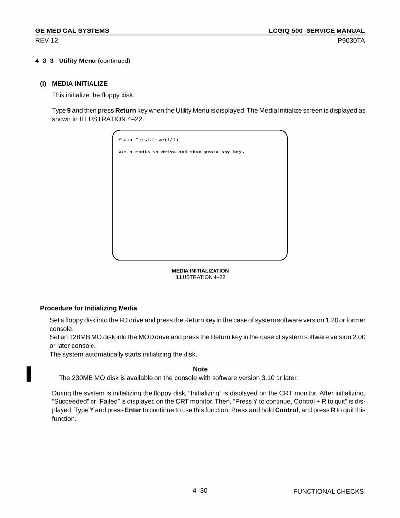
LOGIQ 500 SERVICE MANUALGE MEDICAL SYSTEMS
P9030TA
FUNCTIONAL CHECKS4–30
REV 12
4–3–3 Utility Menu (continued)
(I) MEDIA INITIALIZE
This initialize the floppy disk.
Type 9 and then press Return key when the Utility Menu is displayed. The Media Initialize screen is displayed asshown in ILLUSTRATION 4–22.
MEDIA INITIALIZATIONILLUSTRATION 4–22
Procedure for Initializing Media
Set a floppy disk into the FD drive and press the Return key in the case of system software version 1.20 or formerconsole.Set an 128MB MO disk into the MOD drive and press the Return key in the case of system software version 2.00or later console.The system automatically starts initializing the disk.
NoteThe 230MB MO disk is available on the console with software version 3.10 or later.
During the system is initializing the floppy disk, “Initializing” is displayed on the CRT monitor. After initializing,“Succeeded” or “Failed” is displayed on the CRT monitor. Then, “Press Y to continue, Control + R to quit” is dis-played. Type Y and press Enter to continue to use this function. Press and hold Control, and press R to quit thisfunction.
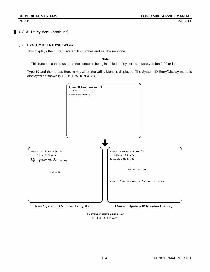
LOGIQ 500 SERVICE MANUALGE MEDICAL SYSTEMS
P9030TA
FUNCTIONAL CHECKS4–31
REV 11
4–3–3 Utility Menu (continued)
(J) SYSTEM ID ENTRY/DISPLAY
This displays the current system ID number and set the new one.
NoteThis function can be used on the consoles being installed the system software version 2.00 or later.
Type 10 and then press Return key when the Utility Menu is displayed. The System ID Entry/Display menu isdisplayed as shown in ILLUSTRATION 4–23.
SYSTEM ID ENTRY/DISPLAYILLUSTRATION 4–23
LOGIQ 500 SERVICE MANUALGE MEDICAL SYSTEMS
P9030TA
FUNCTIONAL CHECKS4–32
REV 11
4–3–3 Utility Menu (continued)
(J) SYSTEM ID ENTRY/DISPLAY (continued)
Procedure for Setting New System ID
1. Type 1 and then press Return key. The system ID number entry menu is displayed as shown inILLUSTRATION 4–23.
2. Type any 5–digit number within the limits of 00000 to 16383 and press the Return key. The new system IDnumber is set.
Procedure for Displaying Current System ID
1. Type 2 and then press Return key. The current system ID number is displayed as shown inILLUSTRATION 4–23.
2. Type Y and then press Return key to continue this function. Press and hold the Control key and press R to exitthis function.
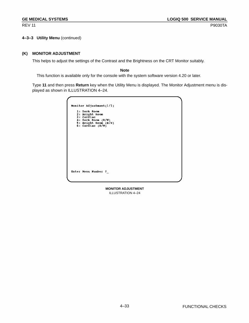
LOGIQ 500 SERVICE MANUALGE MEDICAL SYSTEMS
P9030TA
FUNCTIONAL CHECKS4–33
REV 11
4–3–3 Utility Menu (continued)
(K) MONITOR ADJUSTMENT
This helps to adjust the settings of the Contrast and the Brightness on the CRT Monitor suitably.
NoteThis function is available only for the console with the system software version 4.20 or later.
Type 11 and then press Return key when the Utility Menu is displayed. The Monitor Adjustment menu is dis-played as shown in ILLUSTRATION 4–24.
MONITOR ADJUSTMENTILLUSTRATION 4–24

LOGIQ 500 SERVICE MANUALGE MEDICAL SYSTEMS
P9030TA
FUNCTIONAL CHECKS4–34
REV 11
4–3–3 Utility Menu (continued)
(K) MONITOR ADJUSTMENT (continued)
Procedure for Adjusting Monitor
1. Input the item number according to the brightness of Exam room.The Gray Scale Bar for adjustment will be displayed on the CRT monitor screen as shown inILLUSTRATION 4–25.
GRAY SCALE BARILLUSTRATION 4–25
2. Open the front door at the lower center of the Monitor Assy by pushing the top center of the door.
3. Move Contrast and Brightness slide potentiometers rightwards to the maximum to increase both settings.
4. Decrease brightness by moving Brightness slide potentiometer leftwards by degrees until “B” in the grayscale bar is not visible.
5. Decrease contrast by moving Contrast slide potentiometer leftwards by degrees until “A” in the gray scale baris not visible.
6. Move Brightness slide potentiometer rightwards to the maximum again.
7. Decrease brightness by moving Brightness slide potentiometer leftwards by degrees until “C” in the grayscale bar is not visible.

LOGIQ 500 SERVICE MANUALGE MEDICAL SYSTEMS
P9030TA
FUNCTIONAL CHECKS4–35
REV 14
4–3–3 Utility Menu (continued)
(K) MONITOR ADJUSTMENT (continued)
Procedure for Adjusting Monitor for 15–inch Monitor
1. Press the monitor’s toggle button (2) for brightness and contrast. Confirm that the brightness (or contrast) isdisplayed on the monitor. If the contrast is displayed, press the toggle button again.
1 2 3 4 5
1 Task Light Switch 4 Brightness/Contrast Adjustment (+) Button2 Brightness/Contrast Toggle Button 5 Microphone3 Brightness/Contrast Adjustment (–) Button
GRAY SCALE BARILLUSTRATION 4–26
2. Adjust the brightness (or contrast) by pressing the monitor’s left (3) and right (4) adjustment buttons. Refer toTABLE 4–1 as the monitor adjustment guide.
TABLE 4–1RECOMMENDED CONTRAST AND BRIGHTNESS VALUES
Monitor AdjustmentRoom Condition
Brightness Contrast
Dark room for Radiology/Cardiology
50 20
Dim room forRadiology/Cardiology
65 50
Bright room for OB 50 75
Dark room for Cardiology 45 45
Bright room for Demo 60 90
NoteAfter readjusting the monitor’s Contrast and Brightness, readjust all preset and peripheral settings.
NoteThe process of adjusting Contrast and Brightness for the 15–inch monitor is available on consolesfrom software version 5.00.

LOGIQ 500 SERVICE MANUALGE MEDICAL SYSTEMS
P9030TA
FUNCTIONAL CHECKS4–36
REV 14
4–3–3 Utility Menu (continued)
(L) NETWORK ERROR LOG DISPLAY
This displays and copies an error log file into a MO disk.
NoteThis function is available only when the Storage/Print DICOM option is installed in the console with thesystem software version 4.10 or later.
NoteThis function can be used on the consoles being installed the system software version 4.10 or later.
Type 11 and then press Return key when the Utility Menu is displayed. The Network Error Log Display menu isdisplayed as shown in ILLUSTRATION 4–27.
NoteThe option number of this function is changed to “12” from the software version 4.20.
NETWORK ERROR LOG DISPLAYILLUSTRATION 4–27
Procedure for Saving File
1. Type Y and then press Return key.
2. Insert a MO disk into the MOD drive and press any key.
During the time that the system is copying the error log file, “Copying now” is displayed on the CRT monitorscreen.
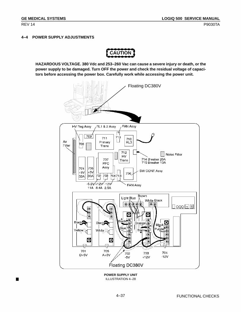
LOGIQ 500 SERVICE MANUALGE MEDICAL SYSTEMS
P9030TA
FUNCTIONAL CHECKS4–37
REV 14
4–4 POWER SUPPLY ADJUSTMENTS
CAUTION
HAZARDOUS VOLTAGE. 380 Vdc and 253–260 Vac can cause a severe injury or death, or thepower supply to be damaged. Turn OFF the power and check the residual voltage of capaci-tors before accessing the power box. Carefully work while accessing the power unit.
ÎÎÎÎ
ÎÎÎÎÎÎÎÎÎÎÎÎÎÎÎÎÎÎÎ
ÎÎÎÎÎÎÎ
ÎÎÎÎÎÎÎÎÎ
ÎÎÎÎÎÎÎÎÎÎÎÎÎÎÎÎÎÎÎÎÎÎÎÎÎÎÎÎÎÎÎÎ
ÎÎ
ÎÎÎÎ
ÎÎÎÎÎÎÎÎ
ÎÎÎ
ÎÎÎÎÎÎ
ÎÎÎÎ
ÎÎÎÎÎÎÎÎÎÎ
ÎÎÎÎÎÎ
ÎÎÎÎÎ
ÎÎÎÎÎ
Î
ÎÎÎÎÎ
ÎÎÎÎÎÎ
ÎÎÎ
ÎÎÎÎÎÎÎ
ÎÎ
ÎÎÎÎÎ
Floating DC380V
POWER SUPPLY UNITILLUSTRATION 4–28

LOGIQ 500 SERVICE MANUALGE MEDICAL SYSTEMS
P9030TA
FUNCTIONAL CHECKS4–38
REV 14
4–4 POWER SUPPLY ADJUSTMENTS (continued)
This section provides power supply adjustment procedures for the LOGIQ 500. Adjustments should be only madewhen necessary. Power supply adjustments should be made in accordance with the schedule for periodic mainte-nance in Chapter 7 of this manual.
Before beginning the power supply adjustments procedure, make sure the power outlet should provide the power linestandards. Refer to Chapter 2, Installation.
NoteIf the adjustment pot is over–turned clockwise, the power supply output is down to protect the circuitsagainst the over–voltage. In that case, power the LOGIQ 500 OFF and turn the pot counterclock-wise all the way. Then power it ON and try to adjust the power supply again.
There are five power supplies in the bottom of the LOGIQ 500. These power supplies are located at the bottom of theconsole as shown in ILLUSTRATION 4–31 on page 4–39.
4–4–1 Power Supply Access
1. Unscrew four screws and remove the Front Cover as shown in the ILLUSTRATION 4–29.
FRONT BASE COVER REMOVALILLUSTRATION 4–29
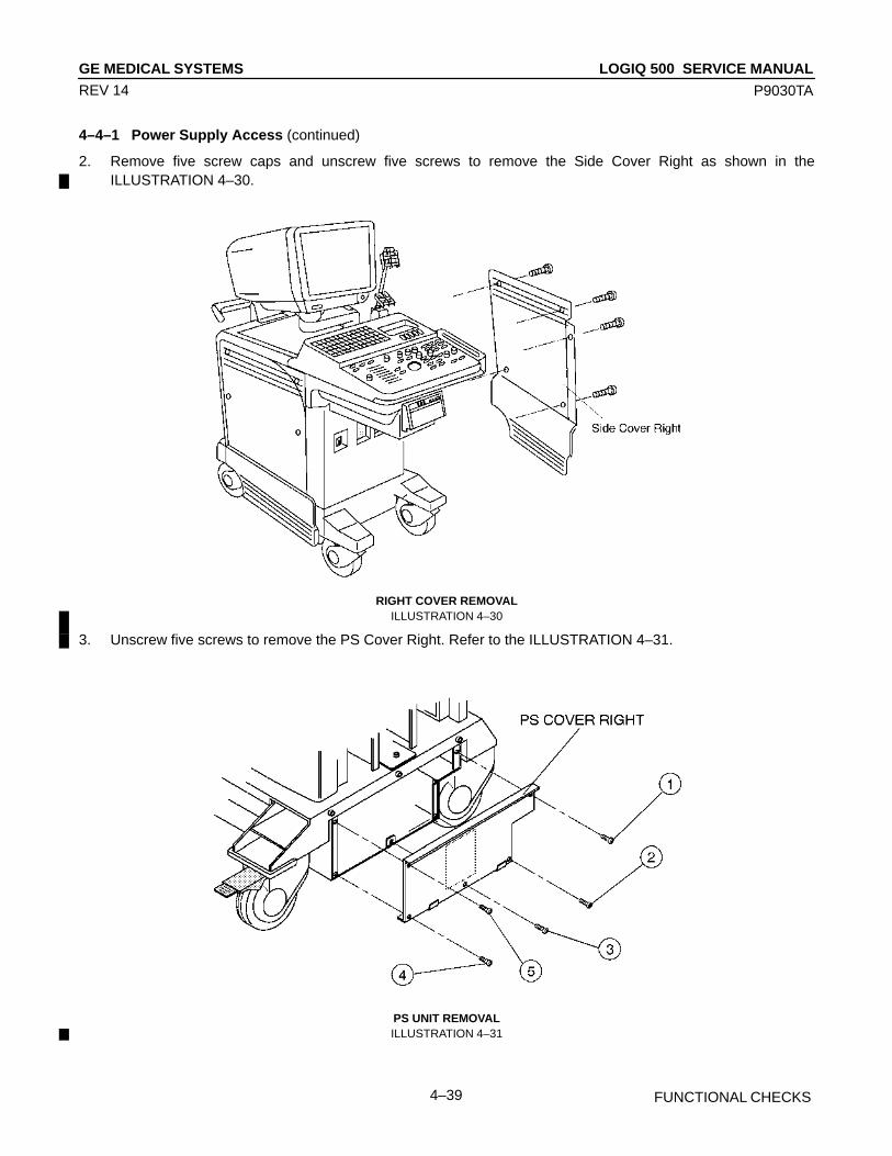
LOGIQ 500 SERVICE MANUALGE MEDICAL SYSTEMS
P9030TA
FUNCTIONAL CHECKS4–39
REV 14
4–4–1 Power Supply Access (continued)
2. Remove five screw caps and unscrew five screws to remove the Side Cover Right as shown in theILLUSTRATION 4–30.
RIGHT COVER REMOVALILLUSTRATION 4–30
3. Unscrew five screws to remove the PS Cover Right. Refer to the ILLUSTRATION 4–31.
PS UNIT REMOVALILLUSTRATION 4–31

LOGIQ 500 SERVICE MANUALGE MEDICAL SYSTEMS
P9030TA
FUNCTIONAL CHECKS4–40
REV 14
4–4–2 Power Supply Adjustment Procedure
1. Power LOGIQ 500 ON. Wait for about 30 seconds to warm up the console.
2. For each of the power supplies which are located at the bottom of LOGIQ 500, connect a DVM to the appropriateplace shown in TABLE 4–2.
3. Verify that the voltages are as shown in TABLE 4–3.
TABLE 4–2POWER SUPPLY MEASUREMENT LOCATION
POWER SUPPLY MEASURE AT RETURN AT
+5V for Digital
–5.2V
+12V
+5V for Analog
–12V
+5V Terminal on Power SupplySee ILLUSTRATION 4–32
+5V Terminal on Power SupplySee ILLUSTRATION 4–32
–5V Terminal on Power SupplySee ILLUSTRATION 4–32
+12V Terminal on Power SupplySee ILLUSTRATION 4–32
–12V Terminal on Power SupplySee ILLUSTRATION 4–32
GND Terminal on Power SupplySee ILLUSTRATION 4–32
GND Terminal on Power SupplySee ILLUSTRATION 4–32
GND Terminal on Power SupplySee ILLUSTRATION 4–32
GND Terminal on Power SupplySee ILLUSTRATION 4–32
GND Terminal on Power SupplySee ILLUSTRATION 4–32
TABLE 4–3POWER SUPPLY MEASUREMENT TOLERANCES
POWER SUPPLY MIN. MAX
+5.0V +5.2V
–5.4V –5.2V
+12.0V +12.5V
–12.5V –12.0V
+5V for Digital
–5.2V
+12V
+5V for Analog
–12V
+5.0V +5.2V
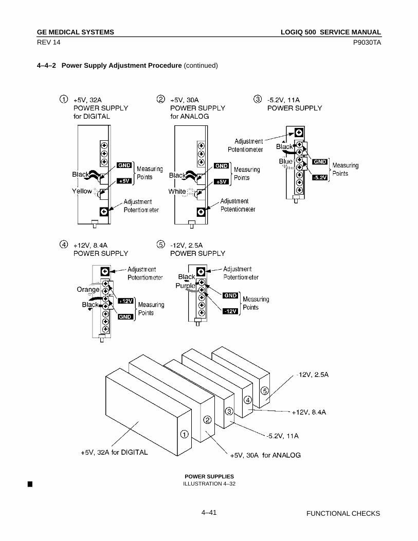
LOGIQ 500 SERVICE MANUALGE MEDICAL SYSTEMS
P9030TA
FUNCTIONAL CHECKS4–41
REV 14
4–4–2 Power Supply Adjustment Procedure (continued)
POWER SUPPLIESILLUSTRATION 4–32

LOGIQ 500 SERVICE MANUALGE MEDICAL SYSTEMS
P9030TA
FUNCTIONAL CHECKS4–42
REV 14
This page is left blank intentionally.

LOGIQ 500 SERVICE MANUALGE MEDICAL SYSTEMS
P9030TA
5–1 DIAGRAMS
REV 5
CHAPTER 5 – DIAGRAMS
TABLE OF CONTENTS
SECTION TITLE PAGE
5–1 INTRODUCTION 5–3. . . . . . . . . . . . . . . . . . . . . . . . . . . . . . . . . . . . . . . . . . . . . . . . . . . . . . . . . . . . . . . . . . . . .
5–2 LOGIQ 500 SYSTEM 5–3. . . . . . . . . . . . . . . . . . . . . . . . . . . . . . . . . . . . . . . . . . . . . . . . . . . . . . . . . . . . . . . . .
5–3 BLOCK DIAGRAM 5–4. . . . . . . . . . . . . . . . . . . . . . . . . . . . . . . . . . . . . . . . . . . . . . . . . . . . . . . . . . . . . . . . . . . .
5–4 WIRING DIAGRAM 5–6. . . . . . . . . . . . . . . . . . . . . . . . . . . . . . . . . . . . . . . . . . . . . . . . . . . . . . . . . . . . . . . . . . .
5–5 POWER SUPPLY BLOCK DIAGRAM 5–8. . . . . . . . . . . . . . . . . . . . . . . . . . . . . . . . . . . . . . . . . . . . . . . . . . .
5–6 CIRCUIT BOARD DESCRIPTION 5–10. . . . . . . . . . . . . . . . . . . . . . . . . . . . . . . . . . . . . . . . . . . . . . . . . . . . .

LOGIQ 500 SERVICE MANUALGE MEDICAL SYSTEMS
P9030TA
5–2 DIAGRAMS
REV 0
This page is left blank intentionally.

LOGIQ 500 SERVICE MANUALGE MEDICAL SYSTEMS
P9030TA
5–3 DIAGRAMS
REV 0
5–1 INTRODUCTION
LOGIQ 500 is a compact ultrasound scanner supporting a wide range of probes. This gives the system added benefitsto meet diverse applications.
5–2 LOGIQ 500 SYSTEM
The LOGIQ 500 has a 64 channel beamformer that digitizes the RF signal. It uses analog and digital delay to focus thebeam. The analog delay is short and fixed. The digital delay is used for long delay and dynamic focus. It offers parallelreceive beam formation which can increase frame rate by a factor of two in time critical applications like Color Flow.This system also features many advanced image processing controls.
User surveys and the latest technology were used to increase console ease–of–use. Digital circuitry enables morereliable and precise operation.
System Features
The key design goals of this system are:
• High Image Quality
• Increased User Productivity
• Multiple Clinical Applications
• Planned Upgradeability
• High Mobility
Types of Applications
The system supports many clinical uses. Scan and display parameters may be user selected to default to desiredvalues for each application. The system presets many parameters to clinically determined, optimal values.
• Radiology
• Cardiology
• OB/GYN, and
• Vascular
See Illustration 5–1, the LOGIQ 500 system can be divided into an analog signal processing section, a digital signalprocessing section, and the microprocessor driven system control section, which controls the system based onoperator commands and system status information.
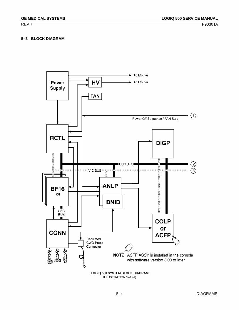
LOGIQ 500 SERVICE MANUALGE MEDICAL SYSTEMS
P9030TA
5–4 DIAGRAMS
REV 7
5–3 BLOCK DIAGRAM
LOGIQ 500 SYSTEM BLOCK DIAGRAMILLUSTRATION 5–1 (a)

LOGIQ 500 SERVICE MANUALGE MEDICAL SYSTEMS
P9030TA
5–5 DIAGRAMS
REV 12
5–3 BLOCK DIAGRAM (continued)
NOTE: The DICOM option is availablefor the console with software ver-sion 4.00 or later.
NOTE: The SCSI port on the Rear Panelis not available on the consolewith the 3.5–inch HDD.
VIPPor
VIPB(or VIDO)
NOTE: VIPP Assy is installed on the con-sole with software version 5.00yor later.
LOGIQ 500 SYSTEM BLOCK DIAGRAMILLUSTRATION 5–1 (b)

LOGIQ 500 SERVICE MANUALGE MEDICAL SYSTEMS
P9030TA
5–6 DIAGRAMS
REV 12
5–4 WIRING DIAGRAM
NOTE: The CB46 and CB45N are notinstalled in the console with thenew 3.5–inch HDD (QuantumFireball 1280S) because theHDD LED Assy is not supplied.
LOGIQ 500 SYSTEM WIRING DIAGRAMILLUSTRATION 5–2 (a)

LOGIQ 500 SERVICE MANUALGE MEDICAL SYSTEMS
P9030TA
5–7 DIAGRAMS
REV 12
5–4 WIRING DIAGRAM (continued)
NOTE: 15–inch Monitor is installed inthe console with the softwareversion 5.00y or later.
LOGIQ 500 SYSTEM WIRING DIAGRAMILLUSTRATION 5–2 (b)
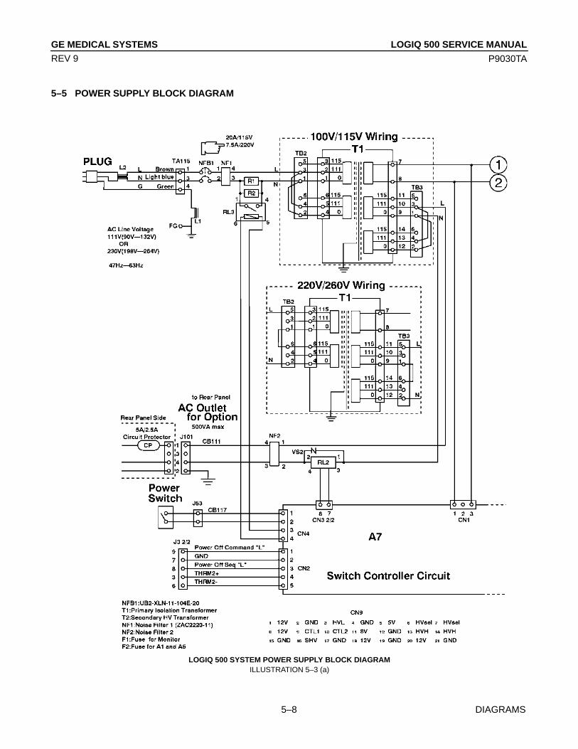
LOGIQ 500 SERVICE MANUALGE MEDICAL SYSTEMS
P9030TA
5–8 DIAGRAMS
REV 9
5–5 POWER SUPPLY BLOCK DIAGRAM
LOGIQ 500 SYSTEM POWER SUPPLY BLOCK DIAGRAMILLUSTRATION 5–3 (a)

LOGIQ 500 SERVICE MANUALGE MEDICAL SYSTEMS
P9030TA
5–9 DIAGRAMS
REV 7
5–5 POWER SUPPLY BLOCK DIAGRAM (Continued)
LOGIQ 500 SYSTEM POWER SUPPLY BLOCK DIAGRAMILLUSTRATION 5–3 (b)

LOGIQ 500 SERVICE MANUALGE MEDICAL SYSTEMS
P9030TA
5–10 DIAGRAMS
REV 12
5–6 CIRCUIT BOARD DESCRIPTION
The following table lists circuit boards and their respective card cage slot assignments on the mother board of theLOGIQ 500 system.
TABLE 5–1CIRCUIT BOARD DESCRIPTION
A0 BF16 ASSY 16 Channel Beam Former AssemblyA1 BF16 ASSY 16 Channel Beam Former AssemblyA2 BF16 ASSY 16 Channel Beam Former AssemblyA3 BF16 ASSY 16 Channel Beam Former AssemblyA4 ANLP ASSY Analog Processor AssemblyA5 RCTL ASSY Real Time Controller AssemblyA6 ReservedA7 DIGP ASSY Digital Processor AssemblyA8 COLP ASSY Color Processor Assembly For V2.50 or former
ACFP ASSY Advanced Color Flow Processor Assembly For V3.00 or laterA9 TLMC ASSY Time Line Memory Processor and Cine
AssemblyA10 DDSC ASSY Dual Digital Scan Converter AssemblyA11 VIPB ASSY Video Output Processor Assembly for USA/Europe/Asia
with VCR Playback Memory systemVIDO ASSY Video Output Processor Assembly for Japanese systemVIPP ASSY Video Assy with Interlace Progressive Scan For V5.00y or later
Converter and VCR PlaybackA12 CPU ASSY CPU Module and CPU Extender Board
Assembly
HV ASSY High Voltage AssemblyCONN ASSY Connector Assembly
CARD CAGE SLOT BOARD NAME DESCRIPTION NOTE

LOGIQ 500 SERVICE MANUALGE MEDICAL SYSTEMS
P9030TA
5–11 DIAGRAMS
REV 14
5–6 CIRCUIT BOARD DESCRIPTION (continued)
TABLE 5–2CIRCUIT BOARD VARIATIONS
BF16 ASSY BF16 ASSY BF16 ASSY can be replaced with BF16–2 ASSY HBBF: 4 HBFC: 5BF16–2 ASSY From software version 2.00 console HBBF: 6 HBFC: 5BF16–3 ASSY For the image appearence, there is no compatibility between BF16–2
Assy and BF16–3 Assy
ANLP ASSY ANLP ASSY ANLP ASSY can be replaced with ANLP_B ASSY 1ANLP_B ASSY For system software version 1.20 or older console 2ANLP2 ASSY 2123291, From software version 2.00 console 4ANLP2 ASSY 2123291–2, From software version 3.00 console 8, 9 or a
Old ANLP2 Assy (2123291) can be replaced with new ANLP2 Assy(2123291–2)
ANLP3 ASSY From software version 4.00 console dANLP3 ASSY 2192674–2, From software version 4.20 console 11
Old ANLP3 Assy (2192674) can be replaced with new ANLP3 Assy2192674–3, From software version 6.00 console 15Old ANLP3 Assy (2192674–2) can be replaced with new ANLP3 Assy
RCTL ASSY RCTL ASSY RCTL ASSY can be replaced with RCTL2 ASSY 1RCTL2 ASSY From software version 2.00 console 4 or 5RCTL2 ASSY 2180314, Required for the P509 probe
DIGP ASSY DIGP ASSY DIGP ASSY is replaced with DIGP2 ASSY by FMI72069 0DIGP2 ASSY DIGP2 ASSY can be replaced with DIGP3 ASSY 4DIGP3 ASSY From software version 2.00 console 8DIGP4 ASSY From software version 3.00 console cDIGP5 ASSY DIGP4 (2123296–2) Assy can be replaced with DIGP5 (2123296–3) Assy 10DIGP6 ASSY From software version 4.00 console 14
COLP ASSY COLP ASSY COLP ASSY is replaced with COLP2 ASSY by FMI72069 0COLP2 ASSY From software version 1.10 console 4COLP3 ASSY COLP3 ASSY can be replaced with COLP3 VAR3 ASSY 8COLP3 VAR2 ASSY COLP3 VAR2 ASSY can be replaced with COLP3 VAR3 ASSY cCOLP3 VAR3 ASSY From software version 2.00 console dCOLP4 ASSY From software version 2.20 console 10
ACFP ASSY From software version 3.00 console 0, 1 or 2ACFP2 ASSY From software version 4.00 console 4ACFP3 ASSY From software version 5.00y console 8
TLMC ASSY TLMC ASSY P9525WY, Software version 2.20 or former 2TLMC ASSY 2158390, From software version 3.00 console 4 or 5
Old TLMC ASSY (P9525WY) can be replaced with new TLMC ASSY(2158390).
TLMC ASSY 2158390–2, Old TLMC ASSY (2158390) can be replaced with new 8TLMC ASSY (2158390–2).
DDSC ASSY DDSC ASSY DDSC ASSY and DDSC2 ASSY have no compatibility. Each 0DDSC2 ASSY assembly has been replaced with equivalent one. DDSC ASSY 4, 8 or 9
should be used only for V1 console and DDSC2 ASSY shouldbe used only for V2 console.
DDSC3 ASSY From software version 4.00 console cDDSC2 Assy can be replaced with DDSC3 Assy
BOARD NAME VARIATIONS NOTE VERSION

LOGIQ 500 SERVICE MANUALGE MEDICAL SYSTEMS
P9030TA
5–12 DIAGRAMS
REV 12
5–6 CIRCUIT BOARD DESCRIPTION (continued)
TABLE 5–3CIRCUIT BOARD VARIATIONS (continued)
VIDO ASSY VIDO ASSY VIDO ASSY is replaced with VIDO2 ASSY by FMI72076 1VIDO2 ASSY 2117032–2 3VIDO2 ASSY 2117032–3, Applied to MVME147–010 8 or 9
Old VIDO2 ASSY (2117032–2) can be replaced with new VIDO2ASSY (2117032–3).
VIPB ASSY VIPB ASSY P9525VA 1VIPB ASSY 2149141, Applied to MVME147–010 4 or 5
Old VIPB ASSY (P9525VA) can be replaced with new VIPB ASSY(2149141).
VIPB2 ASSY 2212616, Available only for console with software version 4.10B or later 8
VIPP ASSY VIPP ASSY 2245652, Available only for console with software version 5.00y or later 0
CPU ASSY CPU ASSY CPU ASSY can be replaced with CPU2 ASSY EXBO: 3 or lessCPU2 ASSY 2131698, From software version 2.00 console EXBO: 3CPU2 ASSY 2131698–2, From software version 3.00 console EXBO: 3
Old CPU2 ASSY (2131698) can be replaced with new CPU2 ASSY(2131698–2).
CPU–A ASSY From software version 4.00 console EXBO: 3
PIOP ASSY PIOP ASSY Included in ECG Board Assy (P9522WZ) 2PIOP2 ASSY Included in ECG Board2 Assy (2207806) 4
BOARD NAME VARIATIONS NOTE VERSION
NoteOn the above table, the VERSION shows the version of each boards displayed on Board Configura-tion Display of Utility Menu.
NoteThe Window ASIC and Gate Array used in some board assemblies are changed. With this change,the revision and settings of DIP switches for the relative board assemblies were changed as follows:
PART NUMBER AND VERSION DISPLAYED ON BOARDBOARD NAME BOARD REVISION CONFIGURATION DISPLAY
OLD NEW OLD NEW
DDSC2 ASSY 2141644–2 Rev.0 2141644–2 Rev.1 8 9
VIPB ASSY 2149141 Rev.0 2149141 Rev.1 4 5
VIDO2 ASSY 2117032–3 Rev.0 2117032–3 Rev.1 8 9
TLMC ASSY 2158390 Rev.0 2158390 Rev.1 4 5
Each board has complete functional compatibility with old version.
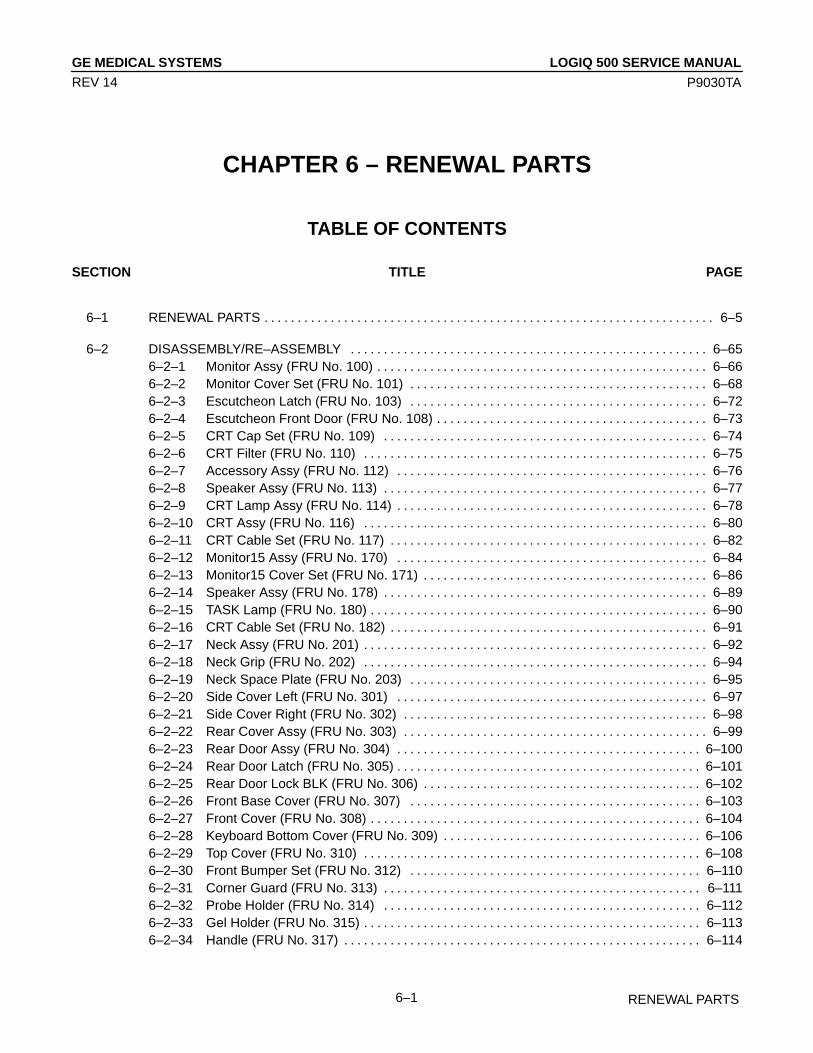
LOGIQ 500 SERVICE MANUALGE MEDICAL SYSTEMS
P9030TA
RENEWAL PARTS6–1
REV 14
CHAPTER 6 – RENEWAL PARTS
TABLE OF CONTENTS
SECTION TITLE PAGE
6–1 RENEWAL PARTS 6–5. . . . . . . . . . . . . . . . . . . . . . . . . . . . . . . . . . . . . . . . . . . . . . . . . . . . . . . . . . . . . . . . . . . .
6–2 DISASSEMBLY/RE–ASSEMBLY 6–65. . . . . . . . . . . . . . . . . . . . . . . . . . . . . . . . . . . . . . . . . . . . . . . . . . . . . . 6–2–1 Monitor Assy (FRU No. 100) 6–66. . . . . . . . . . . . . . . . . . . . . . . . . . . . . . . . . . . . . . . . . . . . . . . . . . 6–2–2 Monitor Cover Set (FRU No. 101) 6–68. . . . . . . . . . . . . . . . . . . . . . . . . . . . . . . . . . . . . . . . . . . . . 6–2–3 Escutcheon Latch (FRU No. 103) 6–72. . . . . . . . . . . . . . . . . . . . . . . . . . . . . . . . . . . . . . . . . . . . . 6–2–4 Escutcheon Front Door (FRU No. 108) 6–73. . . . . . . . . . . . . . . . . . . . . . . . . . . . . . . . . . . . . . . . . 6–2–5 CRT Cap Set (FRU No. 109) 6–74. . . . . . . . . . . . . . . . . . . . . . . . . . . . . . . . . . . . . . . . . . . . . . . . . 6–2–6 CRT Filter (FRU No. 110) 6–75. . . . . . . . . . . . . . . . . . . . . . . . . . . . . . . . . . . . . . . . . . . . . . . . . . . . 6–2–7 Accessory Assy (FRU No. 112) 6–76. . . . . . . . . . . . . . . . . . . . . . . . . . . . . . . . . . . . . . . . . . . . . . . 6–2–8 Speaker Assy (FRU No. 113) 6–77. . . . . . . . . . . . . . . . . . . . . . . . . . . . . . . . . . . . . . . . . . . . . . . . . 6–2–9 CRT Lamp Assy (FRU No. 114) 6–78. . . . . . . . . . . . . . . . . . . . . . . . . . . . . . . . . . . . . . . . . . . . . . . 6–2–10 CRT Assy (FRU No. 116) 6–80. . . . . . . . . . . . . . . . . . . . . . . . . . . . . . . . . . . . . . . . . . . . . . . . . . . . 6–2–11 CRT Cable Set (FRU No. 117) 6–82. . . . . . . . . . . . . . . . . . . . . . . . . . . . . . . . . . . . . . . . . . . . . . . . 6–2–12 Monitor15 Assy (FRU No. 170) 6–84. . . . . . . . . . . . . . . . . . . . . . . . . . . . . . . . . . . . . . . . . . . . . . . 6–2–13 Monitor15 Cover Set (FRU No. 171) 6–86. . . . . . . . . . . . . . . . . . . . . . . . . . . . . . . . . . . . . . . . . . . 6–2–14 Speaker Assy (FRU No. 178) 6–89. . . . . . . . . . . . . . . . . . . . . . . . . . . . . . . . . . . . . . . . . . . . . . . . . 6–2–15 TASK Lamp (FRU No. 180) 6–90. . . . . . . . . . . . . . . . . . . . . . . . . . . . . . . . . . . . . . . . . . . . . . . . . . . 6–2–16 CRT Cable Set (FRU No. 182) 6–91. . . . . . . . . . . . . . . . . . . . . . . . . . . . . . . . . . . . . . . . . . . . . . . . 6–2–17 Neck Assy (FRU No. 201) 6–92. . . . . . . . . . . . . . . . . . . . . . . . . . . . . . . . . . . . . . . . . . . . . . . . . . . . 6–2–18 Neck Grip (FRU No. 202) 6–94. . . . . . . . . . . . . . . . . . . . . . . . . . . . . . . . . . . . . . . . . . . . . . . . . . . . 6–2–19 Neck Space Plate (FRU No. 203) 6–95. . . . . . . . . . . . . . . . . . . . . . . . . . . . . . . . . . . . . . . . . . . . . 6–2–20 Side Cover Left (FRU No. 301) 6–97. . . . . . . . . . . . . . . . . . . . . . . . . . . . . . . . . . . . . . . . . . . . . . . 6–2–21 Side Cover Right (FRU No. 302) 6–98. . . . . . . . . . . . . . . . . . . . . . . . . . . . . . . . . . . . . . . . . . . . . . 6–2–22 Rear Cover Assy (FRU No. 303) 6–99. . . . . . . . . . . . . . . . . . . . . . . . . . . . . . . . . . . . . . . . . . . . . . 6–2–23 Rear Door Assy (FRU No. 304) 6–100. . . . . . . . . . . . . . . . . . . . . . . . . . . . . . . . . . . . . . . . . . . . . . 6–2–24 Rear Door Latch (FRU No. 305) 6–101. . . . . . . . . . . . . . . . . . . . . . . . . . . . . . . . . . . . . . . . . . . . . . 6–2–25 Rear Door Lock BLK (FRU No. 306) 6–102. . . . . . . . . . . . . . . . . . . . . . . . . . . . . . . . . . . . . . . . . . 6–2–26 Front Base Cover (FRU No. 307) 6–103. . . . . . . . . . . . . . . . . . . . . . . . . . . . . . . . . . . . . . . . . . . . 6–2–27 Front Cover (FRU No. 308) 6–104. . . . . . . . . . . . . . . . . . . . . . . . . . . . . . . . . . . . . . . . . . . . . . . . . . 6–2–28 Keyboard Bottom Cover (FRU No. 309) 6–106. . . . . . . . . . . . . . . . . . . . . . . . . . . . . . . . . . . . . . . 6–2–29 Top Cover (FRU No. 310) 6–108. . . . . . . . . . . . . . . . . . . . . . . . . . . . . . . . . . . . . . . . . . . . . . . . . . . 6–2–30 Front Bumper Set (FRU No. 312) 6–110. . . . . . . . . . . . . . . . . . . . . . . . . . . . . . . . . . . . . . . . . . . . 6–2–31 Corner Guard (FRU No. 313) 6–111. . . . . . . . . . . . . . . . . . . . . . . . . . . . . . . . . . . . . . . . . . . . . . . . 6–2–32 Probe Holder (FRU No. 314) 6–112. . . . . . . . . . . . . . . . . . . . . . . . . . . . . . . . . . . . . . . . . . . . . . . . 6–2–33 Gel Holder (FRU No. 315) 6–113. . . . . . . . . . . . . . . . . . . . . . . . . . . . . . . . . . . . . . . . . . . . . . . . . . . 6–2–34 Handle (FRU No. 317) 6–114. . . . . . . . . . . . . . . . . . . . . . . . . . . . . . . . . . . . . . . . . . . . . . . . . . . . . .

LOGIQ 500 SERVICE MANUALGE MEDICAL SYSTEMS
P9030TA
RENEWAL PARTS6–2
REV 14
TABLE OF CONTENTS (continued)
SECTION TITLE PAGE
6–2–35 Air Filter (FRU No. 318A), PW Filter (FRU No. 318B) 6–115. . . . . . . . . . . . . . . . . . . . . . . . . . . 6–2–36 Cable Arm Assy (FRU No. 319) 6–116. . . . . . . . . . . . . . . . . . . . . . . . . . . . . . . . . . . . . . . . . . . . . . 6–2–37 Cable Arm Knob (FRU No. 320) 6–117. . . . . . . . . . . . . . . . . . . . . . . . . . . . . . . . . . . . . . . . . . . . . . 6–2–38 Front Caster (FRU No. 321) 6–118. . . . . . . . . . . . . . . . . . . . . . . . . . . . . . . . . . . . . . . . . . . . . . . . . 6–2–39 Rear Caster (FRU No. 322) 6–119. . . . . . . . . . . . . . . . . . . . . . . . . . . . . . . . . . . . . . . . . . . . . . . . . 6–2–40 Caster Cover Set (FRU No. 323) 6–120. . . . . . . . . . . . . . . . . . . . . . . . . . . . . . . . . . . . . . . . . . . . . 6–2–41 Keyboard Panel Assy and Keyboard Panel2 Assy (FRU No. 400) 6–121. . . . . . . . . . . . . . . . 6–2–42 Keyboard Knob Set (FRU No. 401) 6–122. . . . . . . . . . . . . . . . . . . . . . . . . . . . . . . . . . . . . . . . . . . 6–2–43 Trackball (FRU No. 402) 6–123. . . . . . . . . . . . . . . . . . . . . . . . . . . . . . . . . . . . . . . . . . . . . . . . . . . . 6–2–44 TGC Assy (FRU No. 403) 6–124. . . . . . . . . . . . . . . . . . . . . . . . . . . . . . . . . . . . . . . . . . . . . . . . . . . 6–2–45 I/F Board Assy (FRU No. 405) 6–125. . . . . . . . . . . . . . . . . . . . . . . . . . . . . . . . . . . . . . . . . . . . . . . 6–2–46 A/N Keyboard Assy (FRU No. 406) 6–126. . . . . . . . . . . . . . . . . . . . . . . . . . . . . . . . . . . . . . . . . . . 6–2–47 LED SW Keyboard Set (FRU No. 407) 6–128. . . . . . . . . . . . . . . . . . . . . . . . . . . . . . . . . . . . . . . . 6–2–48 Gain Encoder (FRU No. 408) 6–130. . . . . . . . . . . . . . . . . . . . . . . . . . . . . . . . . . . . . . . . . . . . . . . . 6–2–49 VFD Assy (FRU No. 409) 6–131. . . . . . . . . . . . . . . . . . . . . . . . . . . . . . . . . . . . . . . . . . . . . . . . . . . 6–2–50 Keyboard Case (FRU No. 410) 6–132. . . . . . . . . . . . . . . . . . . . . . . . . . . . . . . . . . . . . . . . . . . . . . 6–2–51 A/N Key–top Set (FRU No. 411) 6–133. . . . . . . . . . . . . . . . . . . . . . . . . . . . . . . . . . . . . . . . . . . . . . 6–2–52 LED SW Key–top Set (FRU No. 412) 6–136. . . . . . . . . . . . . . . . . . . . . . . . . . . . . . . . . . . . . . . . . 6–2–53 Rear CONN Panel Assy (FRU No. 501) and
Rear CONN Panel2 Assy (FRU No. 501B) 6–138. . . . . . . . . . . . . . . . . . . . . . . . . . . . . . . . . . . . 6–2–54 Rear 1 Assy (FRU No. 502) 6–140. . . . . . . . . . . . . . . . . . . . . . . . . . . . . . . . . . . . . . . . . . . . . . . . . 6–2–55 Rear 2 Assy (FRU No. 503) 6–142. . . . . . . . . . . . . . . . . . . . . . . . . . . . . . . . . . . . . . . . . . . . . . . . . 6–2–56 Rear 3 Assy (FRU No. 590) 6–144. . . . . . . . . . . . . . . . . . . . . . . . . . . . . . . . . . . . . . . . . . . . . . . . . 6–2–57 Rear Connector Set (FRU No. 504) 6–145. . . . . . . . . . . . . . . . . . . . . . . . . . . . . . . . . . . . . . . . . . 6–2–58 SCSI Terminator (FRU No. 505) 6–146. . . . . . . . . . . . . . . . . . . . . . . . . . . . . . . . . . . . . . . . . . . . . . 6–2–59 Circuit Protector (FRU No. 506: 7A, FRU No. 507: 3A) 6–147. . . . . . . . . . . . . . . . . . . . . . . . . . 6–2–60 HV Assy (FRU No. 508) 6–148. . . . . . . . . . . . . . . . . . . . . . . . . . . . . . . . . . . . . . . . . . . . . . . . . . . . . 6–2–61 HV Fan Set (FRU No. 509) 6–149. . . . . . . . . . . . . . . . . . . . . . . . . . . . . . . . . . . . . . . . . . . . . . . . . . 6–2–62 ECG Board Assy (FRU No. 510) 6–150. . . . . . . . . . . . . . . . . . . . . . . . . . . . . . . . . . . . . . . . . . . . . 6–2–63 ECG Panel Assy (FRU No. 511) 6–152. . . . . . . . . . . . . . . . . . . . . . . . . . . . . . . . . . . . . . . . . . . . . 6–2–64 Nest Fan Assy (FRU No. 512) 6–154. . . . . . . . . . . . . . . . . . . . . . . . . . . . . . . . . . . . . . . . . . . . . . . 6–2–65 Probe CONN Set Assy (FRU No. 513) 6–156. . . . . . . . . . . . . . . . . . . . . . . . . . . . . . . . . . . . . . . . 6–2–66 Shield Finger Long (FRU No. 514), Shield Finger Short (FRU No. 515) 6–158. . . . . . . . . . . . 6–2–67 Probe CONN 1 Assy (FRU No. 516) 6–159. . . . . . . . . . . . . . . . . . . . . . . . . . . . . . . . . . . . . . . . . . 6–2–68 Probe CONN 2 Assy (FRU No. 517) 6–160. . . . . . . . . . . . . . . . . . . . . . . . . . . . . . . . . . . . . . . . . . 6–2–69 FDD (FRU No. 518), FDD Holder Assy (FRU No. 519) 6–161. . . . . . . . . . . . . . . . . . . . . . . . . . 6–2–70 HDD Assy (FRU No. 520), HDD Holder Assy (FRU No. 521) 6–162. . . . . . . . . . . . . . . . . . . . . 6–2–71 HDDB Assy (FRU No. 522) 6–168. . . . . . . . . . . . . . . . . . . . . . . . . . . . . . . . . . . . . . . . . . . . . . . . . . 6–2–72 HDD LED Assy (FRU No. 523) 6–169. . . . . . . . . . . . . . . . . . . . . . . . . . . . . . . . . . . . . . . . . . . . . . . 6–2–73 Power Switch Assy (FRU No. 525) 6–170. . . . . . . . . . . . . . . . . . . . . . . . . . . . . . . . . . . . . . . . . . . 6–2–74 MODD (FRU No. 540), MODD Fan (FRU No. 541),
MODD Holder Assy (FRU No. 542) 6–172. . . . . . . . . . . . . . . . . . . . . . . . . . . . . . . . . . . . . . . . . . . 6–2–75 P.C. Board(s) (FRU No. 601 through 610) 6–180. . . . . . . . . . . . . . . . . . . . . . . . . . . . . . . . . . . . .

LOGIQ 500 SERVICE MANUALGE MEDICAL SYSTEMS
P9030TA
RENEWAL PARTS6–3
REV 14
TABLE OF CONTENTS (continued)
SECTION TITLE PAGE
6–2–76 Time Keeper RAM (FRU No. 611) 6–182. . . . . . . . . . . . . . . . . . . . . . . . . . . . . . . . . . . . . . . . . . . . 6–2–77 Time Keeper Battery (FRU No. 612) 6–184. . . . . . . . . . . . . . . . . . . . . . . . . . . . . . . . . . . . . . . . . . 6–2–78 Time Keeper RAM (for MVME167–002B) (FRU No. 616) 6–186. . . . . . . . . . . . . . . . . . . . . . . . 6–2–79 OMEM Assy (FRU No. 613) 6–188. . . . . . . . . . . . . . . . . . . . . . . . . . . . . . . . . . . . . . . . . . . . . . . . . 6–2–80 Nest Mother Assy (FRU No. 614) 6–190. . . . . . . . . . . . . . . . . . . . . . . . . . . . . . . . . . . . . . . . . . . . 6–2–81 Mother IC (FRU No. 615) 6–193. . . . . . . . . . . . . . . . . . . . . . . . . . . . . . . . . . . . . . . . . . . . . . . . . . . 6–2–82 DNID2 Assy (FRU No. 620) 6–194. . . . . . . . . . . . . . . . . . . . . . . . . . . . . . . . . . . . . . . . . . . . . . . . . 6–2–83 A1 PS +5V 32A (FRU No. 701) 6–198. . . . . . . . . . . . . . . . . . . . . . . . . . . . . . . . . . . . . . . . . . . . . . 6–2–84 A2 PS –5.2V 11A (FRU No. 702) 6–200. . . . . . . . . . . . . . . . . . . . . . . . . . . . . . . . . . . . . . . . . . . . . 6–2–85 A3 PS +12V 8.4A (FRU No. 703) 6–202. . . . . . . . . . . . . . . . . . . . . . . . . . . . . . . . . . . . . . . . . . . . . 6–2–86 A4 PS –12V 2.5A (FRU No. 704) 6–204. . . . . . . . . . . . . . . . . . . . . . . . . . . . . . . . . . . . . . . . . . . . . 6–2–87 A5 PS +5V 30A (FRU No. 705) 6–206. . . . . . . . . . . . . . . . . . . . . . . . . . . . . . . . . . . . . . . . . . . . . . 6–2–88 A7 SW Cont Assy (FRU No. 706) 6–208. . . . . . . . . . . . . . . . . . . . . . . . . . . . . . . . . . . . . . . . . . . . 6–2–89 A8 PFC Assy (FRU No. 707) 6–210. . . . . . . . . . . . . . . . . . . . . . . . . . . . . . . . . . . . . . . . . . . . . . . . 6–2–90 A10 HV REG Assy (FRU No. 708) 6–212. . . . . . . . . . . . . . . . . . . . . . . . . . . . . . . . . . . . . . . . . . . . 6–2–91 RL1 & 2 Assy (FRU No. 709) 6–214. . . . . . . . . . . . . . . . . . . . . . . . . . . . . . . . . . . . . . . . . . . . . . . . 6–2–92 RL3 (FRU No. 710) 6–216. . . . . . . . . . . . . . . . . . . . . . . . . . . . . . . . . . . . . . . . . . . . . . . . . . . . . . . . . 6–2–93 PS Fan Set (FRU No. 713) 6–218. . . . . . . . . . . . . . . . . . . . . . . . . . . . . . . . . . . . . . . . . . . . . . . . . . 6–2–94 Breaker 20A (FRU No. 714), Breaker 7.5A (FRU No. 715) 6–220. . . . . . . . . . . . . . . . . . . . . . . 6–2–95 Inlet Unit 120V, Inlet Unit 220V (FRU No. 720) 6–222. . . . . . . . . . . . . . . . . . . . . . . . . . . . . . . . . 6–2–96 Inrush Limiter 120V, Inrush Limiter 220V (FRU No. 721) 6–224. . . . . . . . . . . . . . . . . . . . . . . . .
6–3 FUSE REPLACEMENT 6–227. . . . . . . . . . . . . . . . . . . . . . . . . . . . . . . . . . . . . . . . . . . . . . . . . . . . . . . . . . . . . . 6–3–1 Introduction 6–227. . . . . . . . . . . . . . . . . . . . . . . . . . . . . . . . . . . . . . . . . . . . . . . . . . . . . . . . . . . . . . . 6–3–2 Replacement Procedures 6–227. . . . . . . . . . . . . . . . . . . . . . . . . . . . . . . . . . . . . . . . . . . . . . . . . . .
6–4 SYSTEM SOFTWARE INSTALLATION 6–235. . . . . . . . . . . . . . . . . . . . . . . . . . . . . . . . . . . . . . . . . . . . . . . . 6–4–1 Introduction 6–235. . . . . . . . . . . . . . . . . . . . . . . . . . . . . . . . . . . . . . . . . . . . . . . . . . . . . . . . . . . . . . . 6–4–2 Preparing before Installation 6–236. . . . . . . . . . . . . . . . . . . . . . . . . . . . . . . . . . . . . . . . . . . . . . . . . 6–4–3 Initializing Hard Disk 6–237. . . . . . . . . . . . . . . . . . . . . . . . . . . . . . . . . . . . . . . . . . . . . . . . . . . . . . . . 6–4–4 Installing Software 6–238. . . . . . . . . . . . . . . . . . . . . . . . . . . . . . . . . . . . . . . . . . . . . . . . . . . . . . . . . 6–4–5 Final Procedures 6–239. . . . . . . . . . . . . . . . . . . . . . . . . . . . . . . . . . . . . . . . . . . . . . . . . . . . . . . . . . . 6–4–6 Installing Using MO Disk 6–240. . . . . . . . . . . . . . . . . . . . . . . . . . . . . . . . . . . . . . . . . . . . . . . . . . .
6–5 POWER SUPPLY REPLACEMENT 6–243. . . . . . . . . . . . . . . . . . . . . . . . . . . . . . . . . . . . . . . . . . . . . . . . . . . 6–5–1 Introduction 6–243. . . . . . . . . . . . . . . . . . . . . . . . . . . . . . . . . . . . . . . . . . . . . . . . . . . . . . . . . . . . . . . 6–5–2 Replacement Procedure 6–243. . . . . . . . . . . . . . . . . . . . . . . . . . . . . . . . . . . . . . . . . . . . . . . . . . . .
6–6 REPLACING 2.5–INCH HDD ASSY WITH 3.5–INCH HDD ASSY 6–251. . . . . . . . . . . . . . . . . . . . . . . . . 6–6–1 Introduction 6–251. . . . . . . . . . . . . . . . . . . . . . . . . . . . . . . . . . . . . . . . . . . . . . . . . . . . . . . . . . . . . . . 6–6–2 Time Required 6–251. . . . . . . . . . . . . . . . . . . . . . . . . . . . . . . . . . . . . . . . . . . . . . . . . . . . . . . . . . . . . 6–6–3 Parts Required 6–251. . . . . . . . . . . . . . . . . . . . . . . . . . . . . . . . . . . . . . . . . . . . . . . . . . . . . . . . . . . . 6–6–4 Procedures 6–251. . . . . . . . . . . . . . . . . . . . . . . . . . . . . . . . . . . . . . . . . . . . . . . . . . . . . . . . . . . . . . . .

LOGIQ 500 SERVICE MANUALGE MEDICAL SYSTEMS
P9030TA
RENEWAL PARTS6–4
REV 13
LIST OF ABBREVIATIONS
1 Stock item
2 Non stock item
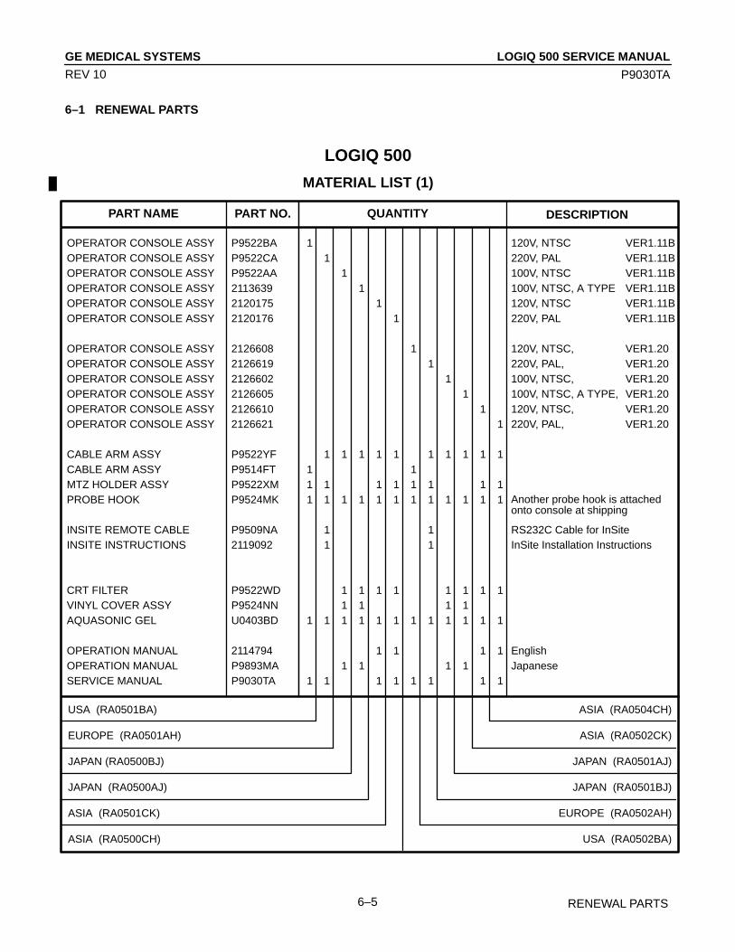
LOGIQ 500 SERVICE MANUALGE MEDICAL SYSTEMS
P9030TA
RENEWAL PARTS6–5
REV 10
6–1 RENEWAL PARTS
LOGIQ 500
MATERIAL LIST (1)
PART NO.PART NAME QUANTITY DESCRIPTION
USA (RA0501BA)
EUROPE (RA0501AH)
JAPAN (RA0500BJ)
JAPAN (RA0500AJ)
ASIA (RA0501CK)
ASIA (RA0500CH)
OPERATOR CONSOLE ASSY P9522BA 1 120V, NTSC VER1.11BOPERATOR CONSOLE ASSY P9522CA 1 220V, PAL VER1.11BOPERATOR CONSOLE ASSY P9522AA 1 100V, NTSC VER1.11BOPERATOR CONSOLE ASSY 2113639 1 100V, NTSC, A TYPE VER1.11BOPERATOR CONSOLE ASSY 2120175 1 120V, NTSC VER1.11BOPERATOR CONSOLE ASSY 2120176 1 220V, PAL VER1.11B
OPERATOR CONSOLE ASSY 2126608 1 120V, NTSC, VER1.20OPERATOR CONSOLE ASSY 2126619 1 220V, PAL, VER1.20OPERATOR CONSOLE ASSY 2126602 1 100V, NTSC, VER1.20OPERATOR CONSOLE ASSY 2126605 1 100V, NTSC, A TYPE, VER1.20OPERATOR CONSOLE ASSY 2126610 1 120V, NTSC, VER1.20OPERATOR CONSOLE ASSY 2126621 1 220V, PAL, VER1.20
CABLE ARM ASSY P9522YF 1 1 1 1 1 1 1 1 1 1CABLE ARM ASSY P9514FT 1 1MTZ HOLDER ASSY P9522XM 1 1 1 1 1 1 1 1PROBE HOOK P9524MK 1 1 1 1 1 1 1 1 1 1 1 1
INSITE REMOTE CABLE P9509NA 1 1 RS232C Cable for InSiteINSITE INSTRUCTIONS 2119092 1 1 InSite Installation Instructions
CRT FILTER P9522WD 1 1 1 1 1 1 1 1VINYL COVER ASSY P9524NN 1 1 1 1AQUASONIC GEL U0403BD 1 1 1 1 1 1 1 1 1 1 1 1
OPERATION MANUAL 2114794 1 1 1 1 EnglishOPERATION MANUAL P9893MA 1 1 1 1 JapaneseSERVICE MANUAL P9030TA 1 1 1 1 1 1 1 1
Another probe hook is attachedonto console at shipping
ASIA (RA0504CH)
ASIA (RA0502CK)
JAPAN (RA0501AJ)
JAPAN (RA0501BJ)
EUROPE (RA0502AH)
USA (RA0502BA)

LOGIQ 500 SERVICE MANUALGE MEDICAL SYSTEMS
P9030TA
RENEWAL PARTS6–6
REV 10
LOGIQ 500
MATERIAL LIST (2)
PART NAME PART NO. QUANTITY DESCRIPTION
USA (RA0503BA)
EUROPE (RA0503AH)
JAPAN (RA0502BJ)
JAPAN (RA0502AJ)
ASIA (RA0503CK)
ASIA (RA0505CH)
OPERATOR CONSOLE ASSY 2126615 1 120V, NTSC VER2.0OPERATOR CONSOLE ASSY 2126624 1 1 220V, PAL VER2.0OPERATOR CONSOLE ASSY 2126607 1 100V, NTSC VER2.0OPERATOR CONSOLE ASSY 2131676 1 100V, NTSC, A TYPE VER2.0OPERATOR CONSOLE ASSY 2126617 1 120V, NTSC VER2.0OPERATOR CONSOLE ASSY 2126626 1 220V, PAL VER2.0
CABLE ARM ASSY P9522YF 1 1 1 1 1 1CABLE ARM ASSY P9514FT 1CABLE ARM SPACER P9510HK 1MTZ HOLDER ASSY P9522XM 1 1 1 1 1PROBE HOOK P9524MK 1 1 1 1 1 1 1
INSITE REMOTE CABLE P9509NA 1 1 RS232C Cable for InSiteINSITE INSTRUCTIONS 2119092 1 1 InSite Installation Instructions
CRT FILTER P9522WD 1 1 1 1 1 1VINYL COVER ASSY P9524NN 1 1AQUASONIC GEL U0403BD 1 1 1 1 1 1 1
V2.00 PRESET MO DISK 2143410 1MO DISK 2131693 1 1 1 1 1 1 13.5 INCH MO CLEANING KIT U0055ZA 1 1 1 1 1 1 1
OPERATION MANUAL 2130977–100 1 1 English (Revision 0)OPERATION MANUAL 2130977–140 1 1 Japanese (Revision 0)QUICK GUIDE 2141643–140 1 1 JapaneseSERVICE MANUAL P9030TA 1 1 1 1 1
FOOT SWITCH P9509NB 1SINGLE CWD 2129360 1EXPANSION CINE MEMORY P9523UC 1PHYSIO SIGNAL FUNCTION P9522WY 1ECG CABLE P9509KH 1
IMAGE ARCHIVE S/W 2131681 1FETAL TREND S/W 2131682 1CINE CAPTURE S/W 2131683 1AMCAL S/W 2131684 1PDI S/W 2131685 1
Another probe hook is attachedonto console at shipping
EUROPE [GEM] (RA0504AH)
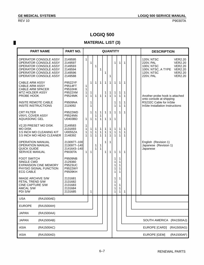
LOGIQ 500 SERVICE MANUALGE MEDICAL SYSTEMS
P9030TA
RENEWAL PARTS6–7
REV 10
LOGIQ 500
MATERIAL LIST (3)
PART NAME PART NO. QUANTITY DESCRIPTION
USA (RA1500AE)
EUROPE (RA1500AH)
JAPAN (RA1500AA)
JAPAN (RA1500AB)
ASIA (RA1500AC)
ASIA (RA1500AD)
OPERATOR CONSOLE ASSY 2149595 1 120V, NTSC VER2.20OPERATOR CONSOLE ASSY 2149597 1 1 1 1 220V, PAL VER2.20OPERATOR CONSOLE ASSY 2149593 1 100V, NTSC VER2.20OPERATOR CONSOLE ASSY 2149594 1 100V, NTSC, A TYPE VER2.20OPERATOR CONSOLE ASSY 2149596 1 120V, NTSC VER2.20OPERATOR CONSOLE ASSY 2149588 1 220V, PAL VER2.20
CABLE ARM ASSY P9522YF 1 1 1 1 1 1 1 1CABLE ARM ASSY P9514FT 1CABLE ARM SPACER P9510HK 1MTZ HOLDER ASSY P9522XM 1 1 1 1 1 1 1PROBE HOOK P9524MK 1 1 1 1 1 1 1 1 1
INSITE REMOTE CABLE P9509NA 1 1 1 1 RS232C Cable for InSiteINSITE INSTRUCTIONS 2119092 1 1 1 1 InSite Installation Instructions
CRT FILTER P9522WD 1 1 1 1 1 1 1 1VINYL COVER ASSY P9524NN 1 1AQUASONIC GEL U0403BD 1 1 1 1 1 1 1
V2.20 PRESET MO DISK 2149583 1MO DISK 2131693 1 1 1 1 1 1 1 1 13.5 INCH MO CLEANING KIT U0055ZA 1 1 1 1 1 1 1 1 13.5 INCH MO HEAD CLEANER 2148392 1 1 1 1 1 1 1 1 1
OPERATION MANUAL 2130977–100 1 1 English (Revision 1)OPERATION MANUAL 2130977–140 1 1 Japanese (Revision 1)QUICK GUIDE 2141643–140 1 1 JapaneseSERVICE MANUAL P9030TA 1 1 1 1 1 1 1
FOOT SWITCH P9509NB 1 1SINGLE CWD 2129360 1 1EXPANSION CINE MEMORY P9523UC 1 1PHYSIO SIGNAL FUNCTION P9522WY 1 1ECG CABLE P9509KH 1 1
IMAGE ARCHIVE S/W 2131681 1 1FETAL TREND S/W 2131682 1CINE CAPTURE S/W 2131683 1 1AMCAL S/W 2131684 1 1PDI S/W 2131685 1 1 1 1
Another probe hook is attachedonto console at shipping
SOUTH AMERICA (RA1500AJ)
EUROPE [CARD] (RA1500AG)
EUROPE [GEM] (RA1500AF)

LOGIQ 500 SERVICE MANUALGE MEDICAL SYSTEMS
P9030TA
RENEWAL PARTS6–8
REV 10
LOGIQ 500
MATERIAL LIST (4)
PART NAME PART NO. QUANTITY DESCRIPTION
USA (RA1500AM)
USA (STD) (RA1500AR)
EUROPE (RA1500AN)
EUROPE (STD) (RA1500AQ)
EUROPE (CARD) (RA1500AP)
JAPAN (RA1500AS)
OPERATOR CONSOLE ASSY 2164533 1 1 120V, NTSC VER3.00OPERATOR CONSOLE ASSY 2164534 1 1 1 220V, PAL VER3.00OPERATOR CONSOLE ASSY 2164531 1 100V, NTSC VER3.00OPERATOR CONSOLE ASSY 2164532 1 100V, NTSC, A TYPE VER3.00OPERATOR CONSOLE ASSY 2164535 1 120V, NTSC VER3.00OPERATOR CONSOLE ASSY 2164536 1 220V, PAL VER3.00
CABLE ARM ASSY P9522YF 1 1 1 1 1 1 1CABLE ARM ASSY P9514FT 1 1CABLE ARM SPACER P9510HK 1 1PROBE HOOK P9524MK 1 1 1 1 1 1 1 1 1MTZ HOLDER ASSY P9522XM 1 1 1 1 1 1 1
INSITE REMOTE CABLE P9509NA 1 1 1 RS232C Cable for InSiteINSITE INSTRUCTIONS 2119092 1 1 1 InSite Installation Instructions
CRT FILTER P9522WD 1 1 1 1 1 1 1VINYL COVER ASSY P9524NN 1 1AQUASONIC GEL U0403BD 1 1 1 1 1 1 1 1 1
V3.00 PRESET MO DISK 2165236 1 1MO DISK 2131693 1 1 1 1 1 1 1 1 13.5 INCH MO CLEANING KIT U0055ZA 1 1 1 1 1 1 1 1 13.5 INCH MO HEAD CLEANER 2148392 1 1 1 1 1 1 1 1 1
OPERATION MANUAL 2156394–100 1 1 English (Revision 0)OPERATION MANUAL 2156394–140 1 1 Japanese (Revision 0)QUICK GUIDE 2137069–100 1 1 EnglishQUICK GUIDE 2141643–140 1 1 JapaneseSERVICE MANUAL P9030TA 1 1 1 1 1 1 1
PDI S/W 2131685 1 1 1IMAGE ARCHIVE S/W 2131681 1 1AMCAL S/W 2131684 1FETAL TREND S/W 2131682 1CINE CAPTURE S/W 2131683 1
EXPANDED CINE MEMORY P9523UC 1PHYSIO SIGNAL FUNCTION P9522WY 1ECG CABLE P9509KH 1SINGLE CWD 2137769 1FOOT SWITCH P9509NB 1
COLOR ENHANCEMENT S/W 2165092 1 1 1 1 1 1MULTIGESTATION S/W 2165093 1 1 1 1 1 1ADVANCED VASCULAR 2165094 1 1 1 1 1
DIGITAL IMAGE SOFTENER S/W 2165095 1 1 1 1 1 1 1START UP MD DISPLAY 2165096 1 1 1 1 1 1 1
Another probe hook is attachedonto console at shipping
ASIA (RA1500AL)
ASIA (RA1500AK)
JAPAN (RA1500AT)
CALCULATION S/W

LOGIQ 500 SERVICE MANUALGE MEDICAL SYSTEMS
P9030TA
RENEWAL PARTS6–9
REV 10
LOGIQ 500
MATERIAL LIST (5)
PART NAME PART NO. QUANTITY DESCRIPTION
USA (RA1501LD, 2179110–3)
EUROPE (RA1501LE, 2179110–6)
EUROPE (CARD) (RA1501LF, 2179110–7)
JAPAN (RA1501LB, 2179110)
JAPAN (RA1501LC, 2179110–2)
ASIA (RA1501LG, 2179110–8)
OPERATOR CONSOLE ASSY 2180824 1 120V, NTSC VER3.10OPERATOR CONSOLE ASSY 2180825 1 1 220V, PAL VER3.10OPERATOR CONSOLE ASSY 2180823 1 100V, NTSC VER3.10OPERATOR CONSOLE ASSY 2177235 1 100V, NTSC, A TYPE VER3.10OPERATOR CONSOLE ASSY 2180826 1 120V, NTSC VER3.10OPERATOR CONSOLE ASSY 2180827 1 220V, PAL VER3.10
CABLE ARM ASSY P9522YF 1 1 1 1 1 1CABLE ARM ASSY P9514FT 1CABLE ARM SPACER P9510HK 1PROBE HOOK P9524MK 1 1 1 1 1 1 1MTZ HOLDER ASSY P9522XM 1 1 1 1 1
INSITE REMOTE CABLE P9509NA 1 1 RS232C Cable for InSiteINSITE INSTRUCTIONS 2119092 1 1 InSite Installation Instructions
CRT FILTER P9522WD 1 1 1 1 1 1VINYL COVER ASSY P9524NN 1 1AQUASONIC GEL U0403BD 1 1 1 1 1 1 1
V3.10 PRESET MO DISK 2180329 1MO DISK 2131693 1 1 1 1 1 1 13.5 INCH MO CLEANING KIT U0055ZA 1 1 1 1 1 1 13.5 INCH MO HEAD CLEANER 2148392 1 1 1 1 1 1 1
OPERATION MANUAL 2177611–100 1 1 English (Revision 0)OPERATION MANUAL 2177611–140 1 1 Japanese (Revision 0)QUICK GUIDE 2137069–100 1 1 EnglishQUICK GUIDE 2141643–140 1 1 JapaneseSERVICE MANUAL P9030TA 1 1 1 1 1
PDI S/W 2131685 1 1IMAGE ARCHIVE S/W 2131681 1 1AMCAL S/W 2131684 1FETAL TREND S/W 2131682 1CINE CAPTURE S/W 2131683 1 1
EXPANDED CINE MEMORY P9523UC 1PHYSIO SIGNAL FUNCTION P9522WY 1ECG CABLE P9509KH 1SINGLE CWD 2137769 1FOOT SWITCH P9509NB 1
COLOR ENHANCEMENT S/W 2165092 1 1 1 1 1 1MULTIGESTATION S/W 2165093 1 1 1 1 1ADVANCED VASCULAR 2165094 1 1 1 1 1
DIGITAL IMAGE SOFTENER S/W 2165095 1 1 1 1 1 1 1START UP MD DISPLAY 2165096 1 1 1 1 1 1 1
Another probe hook is attachedonto console at shipping
ASIA (RA1501LH, 2179110–9)
CALCULATION S/W

LOGIQ 500 SERVICE MANUALGE MEDICAL SYSTEMS
P9030TA
RENEWAL PARTS6–10
REV 10
LOGIQ 500
MATERIAL LIST (6)
PART NAME PART NO. QUANTITY DESCRIPTION
USA (RA1504LC, 2196716–3)
EUROPE (RA1504LD, 2196716–4)
EUROPE (CARD) (RA1504LE, 2196716–5)
JAPAN (RA1504LA, 2196716)
JAPAN (RA1504LB, 2196716–2)
ASIA (RA1504LF, 2196716–6)
OPERATOR CONSOLE ASSY 2196726 1 120V, NTSC VER4.00OPERATOR CONSOLE ASSY 2196727 1 1 220V, PAL VER4.00OPERATOR CONSOLE ASSY 2186725 1 100V, NTSC VER4.00OPERATOR CONSOLE ASSY 2196729 1 100V, NTSC, A TYPE VER4.00OPERATOR CONSOLE ASSY 2196730 1 120V, NTSC VER4.00OPERATOR CONSOLE ASSY 2196731 1 220V, PAL VER4.00
CABLE ARM ASSY P9522YF 1 1 1 1 1 1CABLE ARM ASSY P9514FT 1CABLE ARM SPACER P9510HK 1PROBE HOOK P9524MK 1 1 1 1 1 1 1MTZ HOLDER ASSY P9522XM 1 1 1 1 1
INSITE REMOTE CABLE P9509NA 1 1 RS232C Cable for InSiteINSITE INSTRUCTIONS 2119092 1 1 InSite Installation Instructions
CRT FILTER P9522WD 1 1 1 1 1 1VINYL COVER ASSY P9524NN 1 1AQUASONIC GEL U0403BD 1 1 1 1 1 1 1
MO DISK 2131693 1 1 1 1 1 1 13.5 INCH MO CLEANING KIT U0055ZA 1 1 1 1 1 1 13.5 INCH MO HEAD CLEANER 2148392 1 1 1 1 1 1 1
OPERATION MANUAL 2193631–100 1 1 English (Revision 0)OPERATION MANUAL 2193631–140 1 1 Japanese (Revision 0)QUICK GUIDE 2193742–100 1 1 EnglishQUICK GUIDE 2193742–140 1 1 JapaneseSERVICE MANUAL P9030TA 1 1 1 1 1
IMAGE ARCHIVE S/W 2131681 1 1AMCAL S/W 2131684 1FETAL TREND S/W 2131682 1CINE CAPTURE S/W 2131683 1 1
EXPANDED CINE MEMORY P9523UC 1PHYSIO SIGNAL FUNCTION P9522WY 1ECG CABLE P9509KH 1SINGLE CWD 2137769 1FOOT SWITCH P9509NB 1
COLOR ENHANCEMENT S/W 2165092 1 1 1 1 1 1MULTIGESTATION S/W 2165093 1 1 1 1 1ADVANCED VASCULAR 2165094 1 1 1 1 1 CALCULATION S/WDIGITAL IMAGE SOFTENER S/W 2165095 1 1 1 1 1 1 1
Another probe hook is attachedonto console at shipping
ASIA (RA1504LG, 2196716–7)

LOGIQ 500 SERVICE MANUALGE MEDICAL SYSTEMS
P9030TA
RENEWAL PARTS6–11
REV 11
LOGIQ 500
MATERIAL LIST (7)
PART NAME PART NO. QUANTITY DESCRIPTION
USA (RA1505LF, 2212960–3)
EUROPE (RA1505LG, 2212960–4)
EUROPE (CARD) (RA1505LH, 2212960–5)
JAPAN (RA1505LB, 2212960)
JAPAN (RA1505LC, 2212960–2)
JAPAN (RA1505LD, 2212960–8)
OPERATOR CONSOLE ASSY 2212962 1 120V, NTSC VER4.10OPERATOR CONSOLE ASSY 2212963 1 1 220V, PAL VER4.10OPERATOR CONSOLE ASSY 2212961 1 1 100V, NTSC VER4.10OPERATOR CONSOLE ASSY 2212964 1 1 100V, NTSC, A TYPE VER4.10OPERATOR CONSOLE ASSY 2212965 1 120V, NTSC VER4.10OPERATOR CONSOLE ASSY 2212966 1 220V, PAL VER4.10
CABLE ARM ASSY P9522YF 1 1 1 1 1 1 1 1CABLE ARM ASSY P9514FT 1CABLE ARM SPACER P9510HK 1PROBE HOOK P9524MK 1 1 1 1 1 1 1 1 1MTZ HOLDER ASSY P9522XM 1 1 1 1 1
INSITE REMOTE CABLE P9509NA 1 1 RS232C Cable for InSiteINSITE INSTRUCTIONS 2119092 1 1 InSite Installation Instructions
CRT FILTER P9522WD 1 1 1 1 1 1 1 1VINYL COVER ASSY P9524NN 1 1 1 1AQUASONIC GEL U0403BD 1 1 1 1 1 1 1 1 1
V4.10 AM PRESET MO 2225755 1MO DISK 2131693 1 1 1 1 1 1 1 13.5 INCH MO CLEANING KIT U0055ZA 1 1 1 1 1 1 1 1 13.5 INCH MO HEAD CLEANER 2148392 1 1 1 1 1 1 1 1 1
OPERATION MANUAL 2209829–100 1 1 English (Revision 0)OPERATION MANUAL 2209829–140 1 1 1 1 Japanese (Revision 0)QUICK GUIDE 2193742–100 1 1 EnglishQUICK GUIDE 2193742–140 1 1 1 1 JapaneseSERVICE MANUAL P9030TA 1 1 1 1 1
IMAGE ARCHIVE S/W 2131681 1 1 1 1AMCAL S/W 2131684 1FETAL TREND S/W 2131682 1CINE CAPTURE S/W 2131683 1 1
EXPANDED CINE MEMORY P9523UC 1 1PHYSIO SIGNAL FUNCTION P9522WY 1ECG CABLE P9509KH 1SINGLE CWD 2137769 1FOOT SWITCH P9509NB 1 1 1
Another probe hook is attachedonto console at shipping
ASIA (RA1505LN, 2212960–7)
ASIA (RA1505LM, 2212960–6)
JAPAN (RA1505LE, 2212960–9)

LOGIQ 500 SERVICE MANUALGE MEDICAL SYSTEMS
P9030TA
RENEWAL PARTS6–12
REV 11
LOGIQ 500
MATERIAL LIST (7) (continued)
PART NAME PART NO. QUANTITY DESCRIPTION
USA (RA1505LF, 2212960–3)
EUROPE (RA1505LG, 2212960–4)
EUROPE (CARD) (RA1505LH, 2212960–5)
JAPAN (RA1505LB, 2212960)
JAPAN (RA1505LC, 2212960–2)
JAPAN (RA1505LD, 2212960–8)
ASIA (RA1505LN, 2212960–7)
ASIA (RA1505LM, 2212960–6)
JAPAN (RA1505LE, 2212960–9)
COLOR ENHANCEMENT S/W 2165092 1 1 1 1 1 1 1 1MULTIGESTATION S/W 2165093 1 1 1 1 1 1 1ADVANCED VASCULAR 2165094 1 1 1 1 1 CALCULATION S/WDIGITAL IMAGE SOFTENER S/W 2165095 1 1 1 1 1 1 1 1 1Realtime Doppler Calculation S/W 2197967 1 1 1
CW DOPPLER S/W 2220554 1 1 1 1 1 1 1B COLOR S/W 2220555 1 1 1 1 1 1 1REALTIMEDOPPLER 2220556 1 1 1 1 1 1 1 TRACE S/WOB CALCULATION S/W 2220557 1 1 1 1 1 1 1BASIC CARDIAC S/W 2220558 1 1 1 1 1 1 1
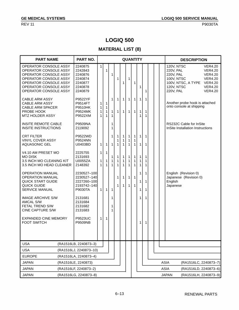
LOGIQ 500 SERVICE MANUALGE MEDICAL SYSTEMS
P9030TA
RENEWAL PARTS6–13
REV 11
LOGIQ 500
MATERIAL LIST (8)
PART NAME PART NO. QUANTITY DESCRIPTION
USA (RA1516LB, 2240873–3)
USA (RA1516LJ, 2240873–10)
EUROPE (RA1516LA, 2240873–4)
JAPAN (RA1516LE, 2240873)
JAPAN (RA1516LF, 2240873–2)
JAPAN (RA1516LG, 2240873–8)
OPERATOR CONSOLE ASSY 2240875 1 120V, NTSC VER4.20OPERATOR CONSOLE ASSY 2242843 1 220V, PAL VER4.20OPERATOR CONSOLE ASSY 2240876 1 220V, PAL VER4.20OPERATOR CONSOLE ASSY 2240874 1 1 100V, NTSC VER4.20OPERATOR CONSOLE ASSY 2240877 1 1 100V, NTSC, A TYPE VER4.20OPERATOR CONSOLE ASSY 2240878 1 120V, NTSC VER4.20OPERATOR CONSOLE ASSY 2240879 1 220V, PAL VER4.20
CABLE ARM ASSY P9522YF 1 1 1 1 1 1 1CABLE ARM ASSY P9514FT 1 1CABLE ARM SPACER P9510HK 1 1PROBE HOOK P9524MK 1 1 1 1 1 1 1 1 1MTZ HOLDER ASSY P9522XM 1 1 1 1 1
INSITE REMOTE CABLE P9509NA 1 RS232C Cable for InSiteINSITE INSTRUCTIONS 2119092 1 InSite Installation Instructions
CRT FILTER P9522WD 1 1 1 1 1 1 1VINYL COVER ASSY P9524NN 1 1 1 1AQUASONIC GEL U0403BD 1 1 1 1 1 1 1 1 1
V4.10 AM PRESET MO 2225755 1 1MO DISK 2131693 1 1 1 1 1 1 13.5 INCH MO CLEANING KIT U0055ZA 1 1 1 1 1 1 1 1 13.5 INCH MO HEAD CLEANER 2148392 1 1 1 1 1 1 1 1 1
OPERATION MANUAL 2230527–100 1 1 English (Revision 0)OPERATION MANUAL 2230527–140 1 1 1 1 Japanese (Revision 0)QUICK START GUIDE 2227260–100 1 1 EnglishQUICK GUIDE 2193742–140 1 1 1 1 JapaneseSERVICE MANUAL P9030TA 1 1 1 1 1
IMAGE ARCHIVE S/W 2131681 1 1 1AMCAL S/W 2131684FETAL TREND S/W 2131682 1CINE CAPTURE S/W 2131683 1
EXPANDED CINE MEMORY P9523UC 1 1FOOT SWITCH P9509NB 1 1
Another probe hook is attachedonto console at shipping
ASIA (RA1516LC, 2240873–7)
ASIA (RA1516LD, 2240873–6)
JAPAN (RA1516LH, 2240873–9)

LOGIQ 500 SERVICE MANUALGE MEDICAL SYSTEMS
P9030TA
RENEWAL PARTS6–14
REV 11
LOGIQ 500
MATERIAL LIST (8) (continued)
PART NAME PART NO. QUANTITY DESCRIPTION
USA (RA1516LB, 2240873–3)
USA (RA1516LJ, 2240873–10)
EUROPE (RA1516LA, 2240873–4)
JAPAN (RA1516LE, 2240873)
JAPAN (RA1516LF, 2240873–2)
JAPAN (RA1516LG, 2240873–8)
ASIA (RA1516LC, 2240873–7)
ASIA (RA1516LD, 2240873–6)
JAPAN (RA1516LH, 2240873–9)
COLOR ENHANCEMENT S/W 2165092 1 1 1 1 1 1 1 1MULTIGESTATION S/W 2165093 1 1 1 1 1 1 1ADVANCED VASCULAR 2165094 1 1 1 1 CALCULATION S/WDIGITAL IMAGE SOFTENER S/W 2165095 1 1 1 1 1 1 1 1 1Realtime Doppler Calculation S/W 2197967 1 1 1 1
CW DOPPLER S/W 2220554 1 1 1 1 1 1 1B COLOR S/W 2220555 1 1 1 1 1 1 1REALTIMEDOPPLER 2220556 1 1 1 1 1 1 1 TRACE S/WOB CALCULATION S/W 2220557 1 1 1 1 1 1 1BASIC CARDIAC S/W 2220558 1 1 1 1 1 1 1
THI S/W 2241568 1 1ATO S/W 2241570 1 1 1 1 1 1 1

LOGIQ 500 SERVICE MANUALGE MEDICAL SYSTEMS
P9030TA
RENEWAL PARTS6–15
REV 12
LOGIQ 500
MATERIAL LIST (9)
PART NAME PART NO. QUANTITY DESCRIPTION
USA (H40172LB, 2250225–5)
USA (H40172LC, 2250225–6)
EUROPE (H40172LA, 2250225–7)
JAPAN (H75002, 2250225)
JAPAN (H75012, 2250225–2)
JAPAN (H75022, 2250225–3)
OPERATOR CONSOLE ASSY 2250227 1 120V, NTSC VER5.00OPERATOR CONSOLE ASSY 2250232 1 220V, PAL VER5.00OPERATOR CONSOLE ASSY 2250228 1 220V, PAL VER5.00OPERATOR CONSOLE ASSY 2250226 1 1 100V, NTSC VER5.00OPERATOR CONSOLE ASSY 2250229 1 1 100V, NTSC, A TYPE VER5.00OPERATOR CONSOLE ASSY 2250230 1 120V, NTSC VER5.00OPERATOR CONSOLE ASSY 2250231 1 220V, PAL VER5.00
CABLE ARM ASSY P9522YF 1 1 1 1 1 1 1CABLE ARM ASSY P9514FT 1 1CABLE ARM SPACER P9510HK 1 1PROBE HOOK P9524MK 1 1 1 1 1 1 1 1 1MTZ HOLDER ASSY P9522XM 1 1 1 1 1
INSITE REMOTE CABLE P9509NA 1 RS232C Cable for InSiteINSITE INSTRUCTIONS 2119092 1 InSite Installation Instructions
BODY COVER 2251995 1 1 1 1AQUASONIC GEL U0403BD 1 1 1 1 1 1 1 1 1MO DISK 2131693 1 1 1 1 1 1 13.5 INCH MO CLEANING KIT U0055ZA 1 1 1 1 1 1 1 1 13.5 INCH MO HEAD CLEANER 2148392 1 1 1 1 1 1 1 1 1
OPERATION MANUAL 2250487–100 1 1 English (Revision 0)OPERATION MANUAL 2250487–140 1 1 1 1 Japanese (Revision 0)QUICK START GUIDE 2237878–100 1 1 EnglishQUICK GUIDE 2193742–140 1 1 1 1 JapaneseSERVICE MANUAL P9030TA 1 1 1 1 1
EXPANDED CINE MEMORY P9523UC 1 1 1 1FOOT SWITCH P9509NB 1 1
Another probe hook is attachedonto console at shipping
ASIA (H40172LD, 2250225–9)
ASIA (H40172LE, 2250225–8)
JAPAN (H75032, 2250225–4)

LOGIQ 500 SERVICE MANUALGE MEDICAL SYSTEMS
P9030TA
RENEWAL PARTS6–16
REV 14
LOGIQ 500
MATERIAL LIST (10)
PART NAME PART NO. QUANTITY DESCRIPTION
USA (H40202LB, 2275350–5)
USA (H40202LC, 2275350–6)
EUROPE (H40202LA, 2275350–7)
JAPAN (H75342, 2275350)
JAPAN (H75352, 2275350–2)
JAPAN (H75362, 2275350–3)
OPERATOR CONSOLE ASSY 2275352 1 120V, NTSC VER6.00OPERATOR CONSOLE ASSY 2275357 1 220V, PAL VER6.00OPERATOR CONSOLE ASSY 2275353 1 220V, PAL VER6.00OPERATOR CONSOLE ASSY 2275351 1 1 100V, NTSC VER6.00OPERATOR CONSOLE ASSY 2275354 1 1 100V, NTSC, A TYPE VER6.00OPERATOR CONSOLE ASSY 2275355 1 120V, NTSC VER6.00OPERATOR CONSOLE ASSY 2275356 1 220V, PAL VER6.00
CABLE ARM ASSY P9522YF 1 1 1 1 1 1 1CABLE ARM ASSY P9514FT 1 1CABLE ARM SPACER P9510HK 1 1PROBE HOOK P9524MK 1 1 1 1 1 1 1 1 1MTZ HOLDER ASSY P9522XM 1 1 1 1 1
INSITE REMOTE CABLE P9509NA 1 RS232C Cable for InSiteINSITE INSTRUCTIONS 2119092 1 InSite Installation Instructions
15 CRT FILTER 2251942 1CONSOLE COVER 2255167 1 1 1 115 MON COVER 2251996 1 1 1 1WARRANTY CARD C ASSY P9889AH 1 1 1 1AQUASONIC GEL U0403BD 1 1 1 1 1 1 1 1 1MO DISK 2131693 1 1 1 1 1 1 1PRESET MO 2275517 1 1 USA3.5 INCH MO CLEANING KIT U0055ZA 1 1 1 1 1 1 1 1 13.5 INCH MO HEAD CLEANER 2148392 1 1 1 1 1 1 1 1 1
OPERATION MANUAL 2250487–100 1 1 English (Revision 0)OPERATION MANUAL 2250487–140 1 1 1 1 Japanese (Revision 0)QUICK START GUIDE 2237878–100 1 1 EnglishQUICK GUIDE 2193742–140 1 1 1 1 JapaneseSERVICE MANUAL P9030TA 1 1 1 1 1
EXPANDED CINE MEMORY P9523UC 1 1 1 1FOOT SWITCH P9509NB 1 1
CAUTION LABEL SET 2255338 1 Europe
Another probe hook is attachedonto console at shipping
ASIA (H40202LD, 2275350–9)
ASIA (H40202LE, 2275350–8)
JAPAN (H75372, 2275350–4)

LOGIQ 500 SERVICE MANUALGE MEDICAL SYSTEMS
P9030TA
RENEWAL PARTS6–17
REV 13
OPERATOR CONSOLE ASSY
POWER SUPPLY(FRU701–718)See ILLUSTRATION 6–10
COVERS(FRU300–323)See ILLUSTRATION 6–5
REAR & RIGHTSIDE ACCESS(FRU501–511, 590)See ILLUSTRATION 6–7
NECK BLOCK(FRU201–203)See ILLUSTRATION 6–4
MONITOR BLOCK(FRU100–117)See ILLUSTRATION 6–2PC BOARDS
(FRU601–620)See ILLUSTRATION 6–9
KEYBOARD BLOCK(FRU400–412)See ILLUSTRATION 6–6
FRONT & UPPERSIDE ACCESS(FRU512–551, 580–582)See ILLUSTRATION 6–8
15–INCH MONITOR BLOCK(FRU170–182)See ILLUSTRATION 6–2b
LOGIQ 500 CONSOLEILLUSTRATION 6–1

LOGIQ 500 SERVICE MANUALGE MEDICAL SYSTEMS
P9030TA
RENEWAL PARTS6–18
REV 11
OPERATOR CONSOLE ASSY 1/9
106
105
116
117
104
114
115
112 109
111
103
108
110
102
113
113
ILLUSTRATION 6–2
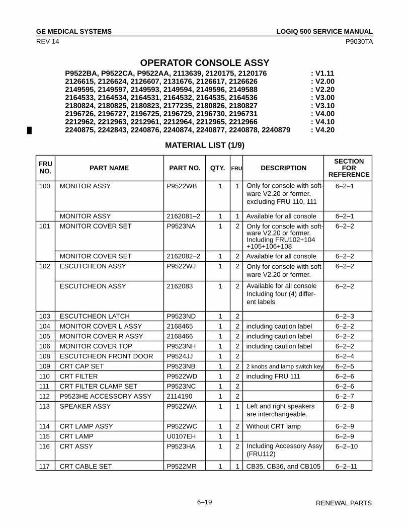
LOGIQ 500 SERVICE MANUALGE MEDICAL SYSTEMS
P9030TA
RENEWAL PARTS6–19
REV 14
OPERATOR CONSOLE ASSYP9522BA, P9522CA, P9522AA, 2113639, 2120175, 2120176 : V1.112126615, 2126624, 2126607, 2131676, 2126617, 2126626 : V2.002149595, 2149597, 2149593, 2149594, 2149596, 2149588 : V2.202164533, 2164534, 2164531, 2164532, 2164535, 2164536 : V3.002180824, 2180825, 2180823, 2177235, 2180826, 2180827 : V3.102196726, 2196727, 2196725, 2196729, 2196730, 2196731 : V4.002212962, 2212963, 2212961, 2212964, 2212965, 2212966 : V4.102240875, 2242843, 2240876, 2240874, 2240877, 2240878, 2240879 : V4.20
MATERIAL LIST (1/9)
SECTIONPART NAME PART NO. QTY. DESCRIPTION FOR
REFERENCE
100 MONITOR ASSY P9522WB 1 1 6–2–1
MONITOR ASSY 2162081–2 1 1 Available for all console 6–2–1
101 MONITOR COVER SET P9523NA 1 2 6–2–2
MONITOR COVER SET 2162082–2 1 2 Available for all console 6–2–2
102 ESCUTCHEON ASSY P9522WJ 1 2 6–2–2
ESCUTCHEON ASSY 2162083 1 2 6–2–2
103 ESCUTCHEON LATCH P9523ND 1 2 6–2–3
104 MONITOR COVER L ASSY 2168465 1 2 including caution label 6–2–2
105 MONITOR COVER R ASSY 2168466 1 2 including caution label 6–2–2
106 MONITOR COVER TOP P9523NH 1 2 including caution label 6–2–2
108 ESCUTCHEON FRONT DOOR P9524JJ 1 2 6–2–4
109 CRT CAP SET P9523NB 1 2 2 knobs and lamp switch key 6–2–5
110 CRT FILTER P9522WD 1 2 including FRU 111 6–2–6
111 CRT FILTER CLAMP SET P9523NC 1 2 6–2–6
112 P9523HE ACCESSORY ASSY 2114190 1 2 6–2–7
113 SPEAKER ASSY P9522WA 1 1 6–2–8
114 CRT LAMP ASSY P9522WC 1 2 Without CRT lamp 6–2–9
115 CRT LAMP U0107EH 1 1 6–2–9
116 CRT ASSY P9523HA 1 2 6–2–10
117 CRT CABLE SET P9522MR 1 1 CB35, CB36, and CB105 6–2–11
FRUNO. FRU
Left and right speakersare interchangeable.
Including Accessory Assy(FRU112)
Only for console with soft-ware V2.20 or former.excluding FRU 110, 111
Only for console with soft-ware V2.20 or former.Including FRU102+104+105+106+108
Only for console with soft-ware V2.20 or former.
Available for all consoleIncluding four (4) differ-ent labels
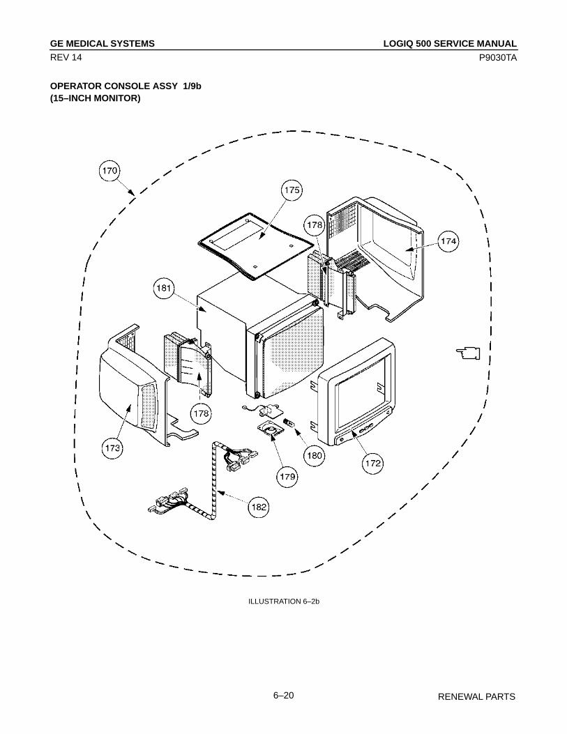
LOGIQ 500 SERVICE MANUALGE MEDICAL SYSTEMS
P9030TA
RENEWAL PARTS6–20
REV 14
OPERATOR CONSOLE ASSY 1/9b(15–INCH MONITOR)
ILLUSTRATION 6–2b

LOGIQ 500 SERVICE MANUALGE MEDICAL SYSTEMS
P9030TA
RENEWAL PARTS6–21
REV 14
OPERATOR CONSOLE ASSY
2250227, 2250232, 2250228, 2250226, 2250229, 2250230, 2250231 : V5.002275352, 2275357, 2275353, 2275351, 2275354, 2275355, 2275356 : V6.00
MATERIAL LIST (1/9b)
SECTIONPART NAME PART NO. QTY. DESCRIPTION FOR
REFERENCE
170 MONITOR15 ASSY 2250404 1 1 6–2–12
171 MONITOR15 COVER SET 2250405 1 2 6–2–13
172 ESCUTCHEON2 ASSY 2250406 1 2 6–2–13
173 MONITOR COVER L2 ASSY 2250407 1 2 including caution label 6–2–13
174 MONITOR COVER R2 ASSY 2250409 1 2 including caution label 6–2–13
175 TRAY2 ASSY 2250410 1 2 including caution label 6–2–13
178 SPEAKER ASSY 2250413 1 1 6–2–14
179 LAMP SHADE2 2246213 1 2
180 TASK LAMP U0107EH 1 1 6–2–15
181 CRT ASSY 2251431 1 2 including tilt mechanism
182 CRT CABLE SET 2251953 1 1 6–2–16
FRUNO. FRU
including FRU 171, 179,180, 181, 182, and 183
including FRU 172, 173,174, and 175
left and right speakers areinterchangeable.

LOGIQ 500 SERVICE MANUALGE MEDICAL SYSTEMS
P9030TA
RENEWAL PARTS6–22
REV 11
OPERATOR CONSOLE ASSY 2/9
203
202
201
ILLUSTRATION 6–3
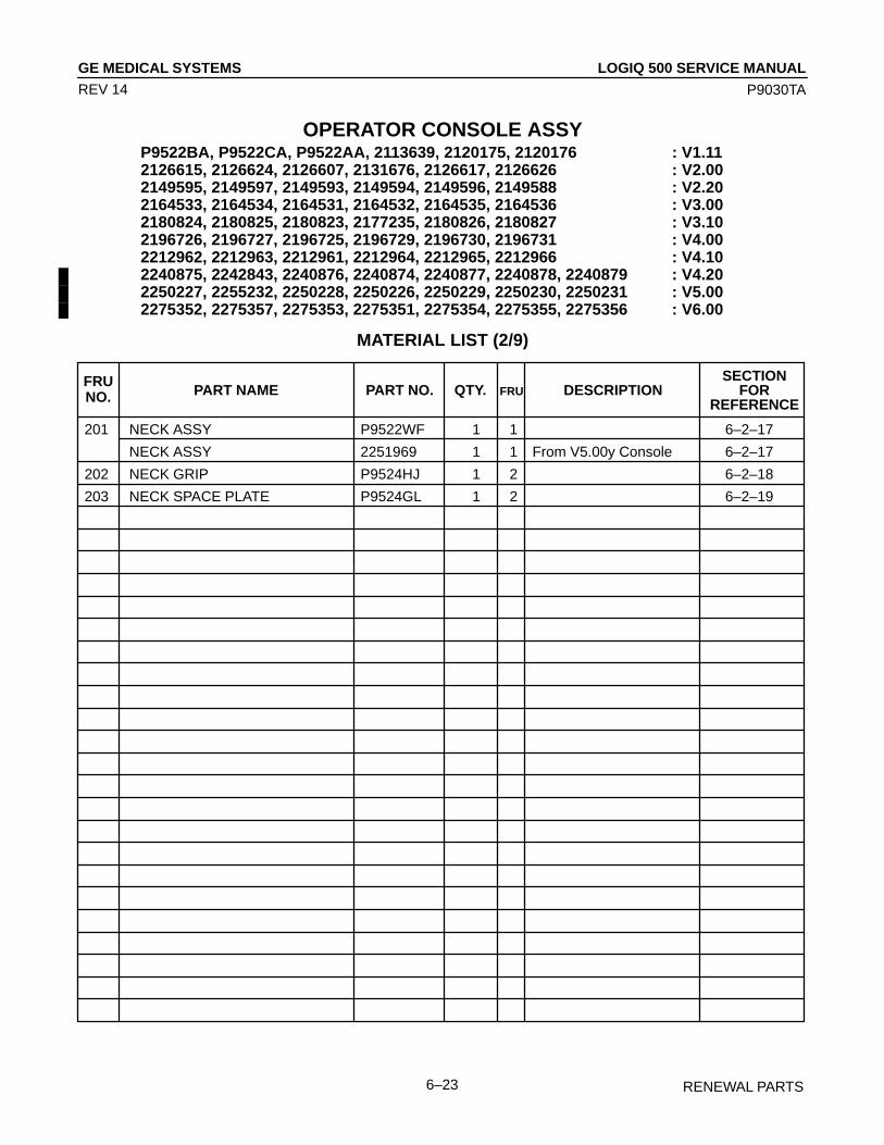
LOGIQ 500 SERVICE MANUALGE MEDICAL SYSTEMS
P9030TA
RENEWAL PARTS6–23
REV 14
OPERATOR CONSOLE ASSYP9522BA, P9522CA, P9522AA, 2113639, 2120175, 2120176 : V1.112126615, 2126624, 2126607, 2131676, 2126617, 2126626 : V2.002149595, 2149597, 2149593, 2149594, 2149596, 2149588 : V2.202164533, 2164534, 2164531, 2164532, 2164535, 2164536 : V3.002180824, 2180825, 2180823, 2177235, 2180826, 2180827 : V3.102196726, 2196727, 2196725, 2196729, 2196730, 2196731 : V4.002212962, 2212963, 2212961, 2212964, 2212965, 2212966 : V4.102240875, 2242843, 2240876, 2240874, 2240877, 2240878, 2240879 : V4.202250227, 2255232, 2250228, 2250226, 2250229, 2250230, 2250231 : V5.002275352, 2275357, 2275353, 2275351, 2275354, 2275355, 2275356 : V6.00
MATERIAL LIST (2/9)
SECTIONPART NAME PART NO. QTY. DESCRIPTION FOR
REFERENCE
201 NECK ASSY P9522WF 1 1 6–2–17
NECK ASSY 2251969 1 1 From V5.00y Console 6–2–17
202 NECK GRIP P9524HJ 1 2 6–2–18
203 NECK SPACE PLATE P9524GL 1 2 6–2–19
FRUNO. FRU

LOGIQ 500 SERVICE MANUALGE MEDICAL SYSTEMS
P9030TA
RENEWAL PARTS6–24
REV 11
OPERATOR CONSOLE ASSY 3/9
304
303
301
322
321
323
308
309
317 311
310319
320
315 316 302
314
313
305
306
312318A
307
312
ILLUSTRATION 6–4
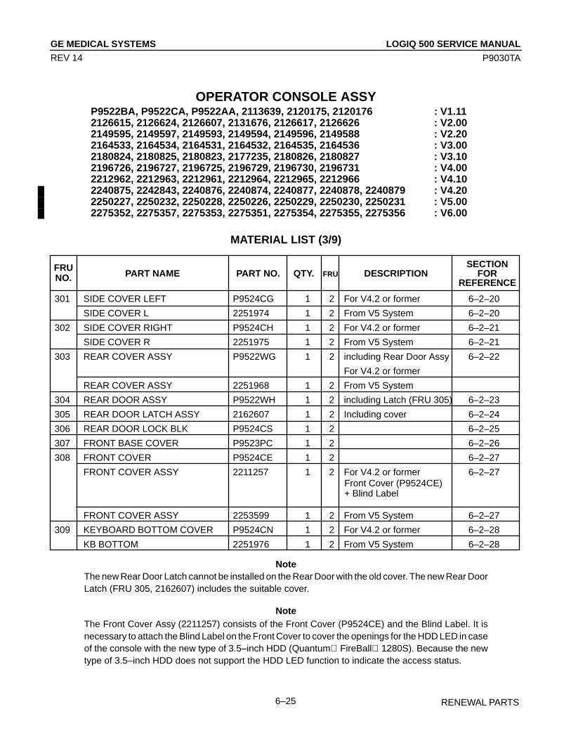
LOGIQ 500 SERVICE MANUALGE MEDICAL SYSTEMS
P9030TA
RENEWAL PARTS6–25
REV 14
OPERATOR CONSOLE ASSYP9522BA, P9522CA, P9522AA, 2113639, 2120175, 2120176 : V1.112126615, 2126624, 2126607, 2131676, 2126617, 2126626 : V2.002149595, 2149597, 2149593, 2149594, 2149596, 2149588 : V2.202164533, 2164534, 2164531, 2164532, 2164535, 2164536 : V3.002180824, 2180825, 2180823, 2177235, 2180826, 2180827 : V3.102196726, 2196727, 2196725, 2196729, 2196730, 2196731 : V4.002212962, 2212963, 2212961, 2212964, 2212965, 2212966 : V4.102240875, 2242843, 2240876, 2240874, 2240877, 2240878, 2240879 : V4.202250227, 2250232, 2250228, 2250226, 2250229, 2250230, 2250231 : V5.002275352, 2275357, 2275353, 2275351, 2275354, 2275355, 2275356 : V6.00
MATERIAL LIST (3/9)
SECTIONPART NAME PART NO. QTY. DESCRIPTION FOR
REFERENCE
301 SIDE COVER LEFT P9524CG 1 2 For V4.2 or former 6–2–20
SIDE COVER L 2251974 1 2 From V5 System 6–2–20
302 SIDE COVER RIGHT P9524CH 1 2 For V4.2 or former 6–2–21
SIDE COVER R 2251975 1 2 From V5 System 6–2–21
303 REAR COVER ASSY P9522WG 1 2 including Rear Door Assy 6–2–22
For V4.2 or former
REAR COVER ASSY 2251968 1 2 From V5 System
304 REAR DOOR ASSY P9522WH 1 2 including Latch (FRU 305) 6–2–23
305 REAR DOOR LATCH ASSY 2162607 1 2 Including cover 6–2–24
306 REAR DOOR LOCK BLK P9524CS 1 2 6–2–25
307 FRONT BASE COVER P9523PC 1 2 6–2–26
308 FRONT COVER P9524CE 1 2 6–2–27
FRONT COVER ASSY 2211257 1 2 For V4.2 or former 6–2–27
FRONT COVER ASSY 2253599 1 2 From V5 System 6–2–27
309 KEYBOARD BOTTOM COVER P9524CN 1 2 For V4.2 or former 6–2–28
KB BOTTOM 2251976 1 2 From V5 System 6–2–28
FRUNO. FRU
Front Cover (P9524CE)+ Blind Label
NoteThe new Rear Door Latch cannot be installed on the Rear Door with the old cover. The new Rear DoorLatch (FRU 305, 2162607) includes the suitable cover.
NoteThe Front Cover Assy (2211257) consists of the Front Cover (P9524CE) and the Blind Label. It isnecessary to attach the Blind Label on the Front Cover to cover the openings for the HDD LED in caseof the console with the new type of 3.5–inch HDD (Quantum FireBall 1280S). Because the newtype of 3.5–inch HDD does not support the HDD LED function to indicate the access status.

LOGIQ 500 SERVICE MANUALGE MEDICAL SYSTEMS
P9030TA
RENEWAL PARTS6–26
REV 14
OPERATOR CONSOLE ASSYP9522BA, P9522CA, P9522AA, 2113639, 2120175, 2120176 : V1.112126615, 2126624, 2126607, 2131676, 2126617, 2126626 : V2.002149595, 2149597, 2149593, 2149594, 2149596, 2149588 : V2.202164533, 2164534, 2164531, 2164532, 2164535, 2164536 : V3.002180824, 2180825, 2180823, 2177235, 2180826, 2180827 : V3.102196726, 2196727, 2196725, 2196729, 2196730, 2196731 : V4.002212962, 2212963, 2212961, 2212964, 2212965, 2212966 : V4.102240875, 2242843, 2240876, 2240874, 2240877, 2240878, 2240879 : V4.202250227, 2250232, 2250228, 2250226, 2250229, 2250230, 2250231 : V5.002275352, 2275357, 2275353, 2275351, 2275354, 2275355, 2275356 : V6.00
MATERIAL LIST (3/9) (continued)
SECTIONPART NAME PART NO. QTY. DESCRIPTION FOR
REFERENCE
310 TOP COVER P9524CD 1 2 For V4.2 or former 6–2–29
TOP COVER 2251973 1 2 From V5 System 6–2–29
311 TOP COVER SHEET P9524CV 1 2
312 FRONT BUMPER SET P9523NJ 1 2 left and right bumpers 6–2–30
BUMPER LONG 2251921 1 2 For V5 Tall Version
313 CORNER GUARD P9524MJ 1 2 Keyboard bumper 6–2–31
314 PROBE HOLDER P9524MD 1 2 6–2–32
PROBE HOLDER 2135393 1 2 For V2.0 or later console 6–2–32
315 GEL HOLDER P9524MF 1 2 6–2–33
316 GEL HOLDER BOTTOM P9524MG 1 2 6–2–33
317 HANDLE P9524BC 1 2 6–2–34
318A AIR FILTER P9524BJ 1 2 6–2–35
318B P9524SD PW FILTER 2112668 1 2 6–2–35
319 CABLE ARM ASSY P9510KK 1 2 6–2–36
320 CABLE ARM KNOB P9510KQ 1 2 1 Knob 6–2–37
321 FRONT CASTER ASSY P9523PD 1 2 6–2–38
322 REAR CASTER ASSY P9523PE 1 2 6–2–39
323 CASTER COVER ASSY P9523NE 1 2 1 cover 6–2–40
FRUNO. FRU
2 filters are used in aconsole
left and right BUMPERLONG are interchangeable.

LOGIQ 500 SERVICE MANUALGE MEDICAL SYSTEMS
P9030TA
RENEWAL PARTS6–27
REV 11
This page is left blank intentionally.
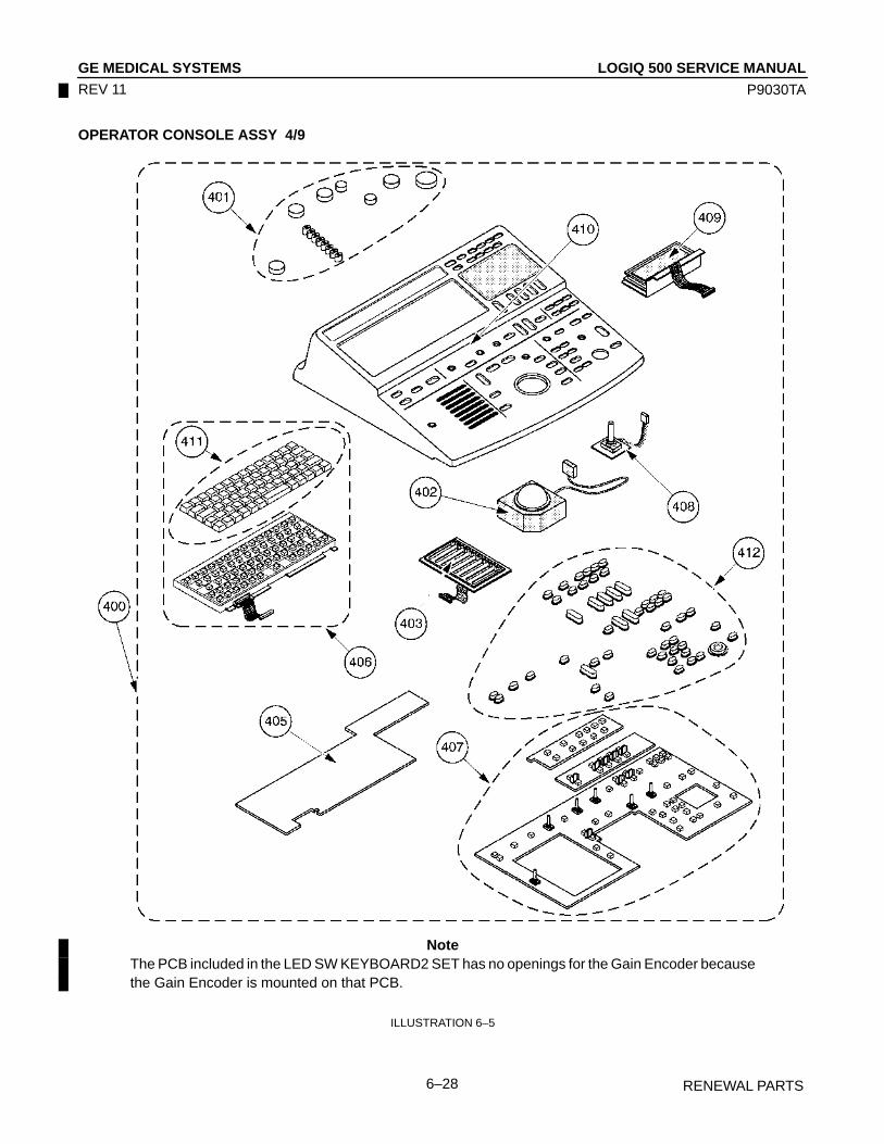
LOGIQ 500 SERVICE MANUALGE MEDICAL SYSTEMS
P9030TA
RENEWAL PARTS6–28
REV 11
OPERATOR CONSOLE ASSY 4/9
NoteThe PCB included in the LED SW KEYBOARD2 SET has no openings for the Gain Encoder becausethe Gain Encoder is mounted on that PCB.
ILLUSTRATION 6–5
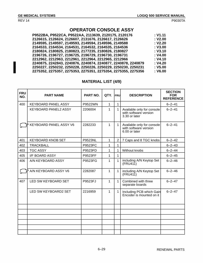
LOGIQ 500 SERVICE MANUALGE MEDICAL SYSTEMS
P9030TA
RENEWAL PARTS6–29
REV 14
OPERATOR CONSOLE ASSYP9522BA, P9522CA, P9522AA, 2113639, 2120175, 2120176 : V1.112126615, 2126624, 2126607, 2131676, 2126617, 2126626 : V2.002149595, 2149597, 2149593, 2149594, 2149596, 2149588 : V2.202164533, 2164534, 2164531, 2164532, 2164535, 2164536 : V3.002180824, 2180825, 2180823, 2177235, 2180826, 2180827 : V3.102196726, 2196727, 2196725, 2196729, 2196730, 2196731 : V4.002212962, 2212963, 2212961, 2212964, 2212965, 2212966 : V4.102240875, 2242843, 2240876, 2240874, 2240877, 2240878, 2240879 : V4.202250227, 2250232, 2250228, 2250226, 2250229, 2250230, 2250231 : V5.002275352, 2275357, 2275353, 2275351, 2275354, 2275355, 2275356 : V6.00
MATERIAL LIST (4/9)
SECTIONPART NAME PART NO. QTY. DESCRIPTION FOR
REFERENCE
400 KEYBOARD PANEL ASSY P9522WN 1 1 6–2–41
KEYBOARD PANEL2 ASSY 2206004 1 1 6–2–41
KEYBOARD PANEL ASSY V6 2282233 1 1 6–2–41
401 KEYBOARD KNOB SET P9523NL 1 2 7 Caps and 8 TGC knobs 6–2–42
402 TRACKBALL P9523FC 1 1 6–2–43
403 TGC ASSY P9523FD 1 1 Without knobs 6–2–44
405 I/F BOARD ASSY P9523FF 1 1 6–2–45
406 A/N KEYBOARD ASSY P9523FG 1 1 6–2–46
A/N KEYBOARD ASSY V6 2282087 1 1 6–2–46
407 LED SW KEYBOARD SET P9523FJ 1 1 6–2–47
LED SW KEYBOARD2 SET 2216959 1 1 6–2–47
FRUNO. FRU
including A/N Keytop Set(FRU411)
Combined with threeseparate boards
Available only for consolewith software version3.30 or later
Including PCB which GainEncoder is mounted on it
Available only for consolewith software version6.00 or later
including A/N Keytop Set(FRU411)
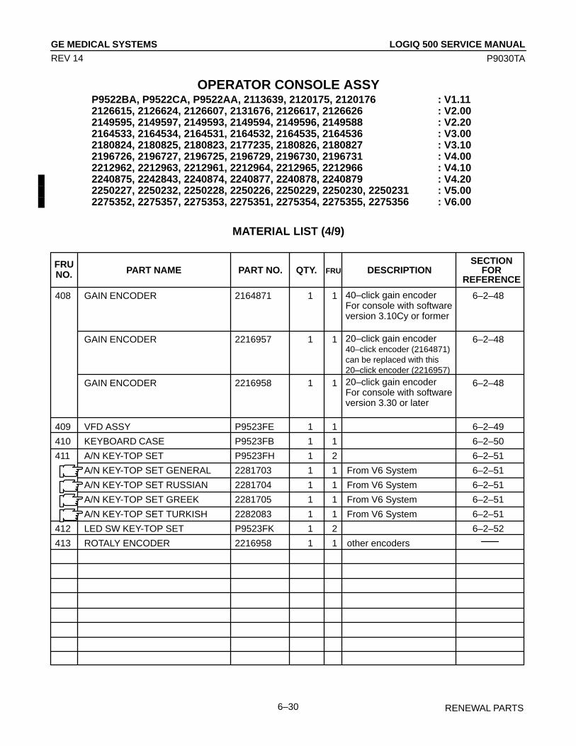
LOGIQ 500 SERVICE MANUALGE MEDICAL SYSTEMS
P9030TA
RENEWAL PARTS6–30
REV 14
OPERATOR CONSOLE ASSYP9522BA, P9522CA, P9522AA, 2113639, 2120175, 2120176 : V1.112126615, 2126624, 2126607, 2131676, 2126617, 2126626 : V2.002149595, 2149597, 2149593, 2149594, 2149596, 2149588 : V2.202164533, 2164534, 2164531, 2164532, 2164535, 2164536 : V3.002180824, 2180825, 2180823, 2177235, 2180826, 2180827 : V3.102196726, 2196727, 2196725, 2196729, 2196730, 2196731 : V4.002212962, 2212963, 2212961, 2212964, 2212965, 2212966 : V4.102240875, 2242843, 2240874, 2240877, 2240878, 2240879 : V4.202250227, 2250232, 2250228, 2250226, 2250229, 2250230, 2250231 : V5.002275352, 2275357, 2275353, 2275351, 2275354, 2275355, 2275356 : V6.00
MATERIAL LIST (4/9)
SECTIONPART NAME PART NO. QTY. DESCRIPTION FOR
REFERENCE
408 GAIN ENCODER 2164871 1 1 6–2–48
GAIN ENCODER 2216957 1 1 6–2–48
GAIN ENCODER 2216958 1 1 6–2–48
409 VFD ASSY P9523FE 1 1 6–2–49
410 KEYBOARD CASE P9523FB 1 1 6–2–50
411 A/N KEY-TOP SET P9523FH 1 2 6–2–51
A/N KEY-TOP SET GENERAL 2281703 1 1 From V6 System 6–2–51
A/N KEY-TOP SET RUSSIAN 2281704 1 1 From V6 System 6–2–51
A/N KEY-TOP SET GREEK 2281705 1 1 From V6 System 6–2–51
A/N KEY-TOP SET TURKISH 2282083 1 1 From V6 System 6–2–51
412 LED SW KEY-TOP SET P9523FK 1 2 6–2–52
413 ROTALY ENCODER 2216958 1 1 other encoders
FRUNO. FRU
40–click gain encoderFor console with softwareversion 3.10Cy or former
20–click gain encoderFor console with softwareversion 3.30 or later
20–click gain encoder40–click encoder (2164871)can be replaced with this20–click encoder (2216957)

LOGIQ 500 SERVICE MANUALGE MEDICAL SYSTEMS
P9030TA
RENEWAL PARTS6–31
REV 14
This page is left blank intentionally.

LOGIQ 500 SERVICE MANUALGE MEDICAL SYSTEMS
P9030TA
RENEWAL PARTS6–32
REV 14
OPERATOR CONSOLE ASSY 5/9
506
FRU501
FRU508
507
505
504
509
503502
511
510
FRU501B
590
ILLUSTRATION 6–6

LOGIQ 500 SERVICE MANUALGE MEDICAL SYSTEMS
P9030TA
RENEWAL PARTS6–33
REV 14
OPERATOR CONSOLE ASSYP9522BA, P9522CA, P9522AA, 2113639, 2120175, 2120176 : V1.112126615, 2126624, 2126607, 2131676, 2126617, 2126626 : V2.002149595, 2149597, 2149593, 2149594, 2149596, 2149588 : V2.202164533, 2164534, 2164531, 2164532, 2164535, 2164536 : V3.002180824, 2180825, 2180823, 2177235, 2180826, 2180827 : V3.102196726, 2196727, 2196725, 2196729, 2196730, 2196731 : V4.002212962, 2212963, 2212961, 2212964, 2212965, 2212966 : V4.102240875, 2242843, 2240876, 2240874, 2240877, 2240878, 2240879 : V4.202250227, 2250232, 2250228, 2250226, 2250229, 2250230, 2250231 : V5.002275352, 2275357, 2275353, 2275351, 2275354, 2275355, 2275356 : V6.00
MATERIAL LIST (5/9)
SECTIONPART NAME PART NO. QTY. DESCRIPTION FOR
REFERENCE
501 REAR CONN PANEL ASSY P9522WK 1 1 For Japan 6–2–53
REAR CONN PANEL ASSY P9522WV 1 1 For USA/Asia 6–2–53
REAR CONN PANEL ASSY P9522WW 1 1 6–2–53
501B REAR CONN PANEL2 ASSY 2211163 1 1 For Japan 6–2–53
REAR CONN PANEL2 ASSY 2211164 1 1 For USA/Asia 6–2–53
REAR CONN PANEL2 ASSY 2211166 1 1 6–2–53
502 REAR 1 ASSY P9525XL 1 2 6–2–54
503 REAR 2 ASSY P9525XN 1 2 6–2–55
504 REAR CONNECTOR SET P9523PL 1 2 6–2–57
505 SCSI TERMINATOR U0463FD 1 1 6–2–58
FRUNO. FRU
This is not included inconsole with 3.5–inchHDD
For Europe[FRU501 includes FRU502, 503, 504, 505, 506 (or 507)]
For Europe[FRU501B includes FRU502, 504, 506 (or 507) and 513]
Used only for Rear CONNPanel Assy (P9522WK, WV, and WW)
BNC:4, AUDIO:2, DIN:1,and Y/C:1Used only for Rear1Assy (P9522WL)
NoteThe new Rear CONN Panel2 Assy cannot be used for the console with the 2.5–inch HDD Assy be-cause the SCSI termination is made with the external SCSI Terminator plug on the old Rear CONNPanel Assy. The new Rear CONN Panel2 Assy does not have the external SCSI connector.

LOGIQ 500 SERVICE MANUALGE MEDICAL SYSTEMS
P9030TA
RENEWAL PARTS6–34
REV 14
OPERATOR CONSOLE ASSYP9522BA, P9522CA, P9522AA, 2113639, 2120175, 2120176 : V1.112126615, 2126624, 2126607, 2131676, 2126617, 2126626 : V2.002149595, 2149597, 2149593, 2149594, 2149596, 2149588 : V2.202164533, 2164534, 2164531, 2164532, 2164535, 2164536 : V3.002180824, 2180825, 2180823, 2177235, 2180826, 2180827 : V3.102196726, 2196727, 2196725, 2196729, 2196730, 2196731 : V4.002212962, 2212963, 2212961, 2212964, 2212965, 2212966 : V4.102240875, 2242843, 2240876, 2240874, 2240877, 2240878, 2240879 : V4.202250227, 2250232, 2250228, 2250226, 2250229, 2250230, 2250231 : V5.002275352, 2275357, 2275353, 2275351, 2275354, 2275355, 2275356 : V6.00
MATERIAL LIST (5/9) (continued)
SECTIONPART NAME PART NO. QTY. DESCRIPTION FOR
REFERENCE
506 CIRCUIT PROTECTOR 7A U0027EK 1 1 For P9522BA 6–2–59
507 CIRCUIT PROTECTOR 3A U0026EK 1 1 For P9522CA 6–2–59
508 HV ASSY P9523DC 1 1 With cover 6–2–60
509 HV FAN SET P9522QZ 1 1 2 Fans 6–2–61
510 ECG BOARD ASSY P9522WZ 1 1 6–2–62
ECG BOARD2 ASSY 2207806 1 1 From V5 System 6–2–62
511 ECG PANEL ASSY P9522XB 1 1 6–2–63
ECG CONN PNL ASSY 2251836 1 1 From V5 System 6–2–63
590 REAR3 ASSY 2200670 1 2 6–2–56
FRUNO. FRU
Old ECG Board Assy(P9522WZ) can be re-placed with new ECGBoard2 Assy (2207806)
Used only for Rear CONNPanel2 Assy (2211163,2211164, and 2211166)

LOGIQ 500 SERVICE MANUALGE MEDICAL SYSTEMS
P9030TA
RENEWAL PARTS6–35
REV 14
This page is left blank intentionally.

LOGIQ 500 SERVICE MANUALGE MEDICAL SYSTEMS
P9030TA
RENEWAL PARTS6–36
REV 14
OPERATOR CONSOLE ASSY 6/9
520
521
518
519
522
512
523
517
516 or 582
514
515
FRU513
525
541
540
542
ILLUSTRATION 6–7
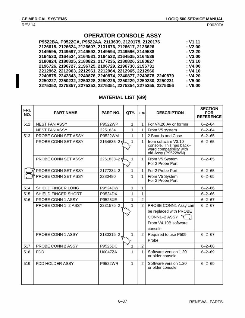
LOGIQ 500 SERVICE MANUALGE MEDICAL SYSTEMS
P9030TA
RENEWAL PARTS6–37
REV 14
OPERATOR CONSOLE ASSYP9522BA, P9522CA, P9522AA, 2113639, 2120175, 2120176 : V1.112126615, 2126624, 2126607, 2131676, 2126617, 2126626 : V2.002149595, 2149597, 2149593, 2149594, 2149596, 2149588 : V2.202164533, 2164534, 2164531, 2164532, 2164535, 2164536 : V3.002180824, 2180825, 2180823, 2177235, 2180826, 2180827 : V3.102196726, 2196727, 2196725, 2196729, 2196730, 2196731 : V4.002212962, 2212963, 2212961, 2212964, 2212965, 2212966 : V4.102240875, 2242843, 2240876, 2240874, 2240877, 2240878, 2240879 : V4.202250227, 2250232, 2250228, 2250226, 2250229, 2250230, 2250231 : V5.002275352, 2275357, 2275353, 2275351, 2275354, 2275355, 2275356 : V6.00
MATERIAL LIST (6/9)
SECTIONPART NAME PART NO. QTY. DESCRIPTION FOR
REFERENCE
512 NEST FAN ASSY P9522WP 1 1 For V4.20 Ay or former 6–2–64
NEST FAN ASSY 2251834 1 1 From V5 system 6–2–64
513 PROBE CONN SET ASSY P9522WM 1 1 2 Boards and Case 6–2–65
PROBE CONN SET ASSY 2164635–2 1 1 6–2–65
PROBE CONN SET ASSY 2251833–2 1 1 From V5 System 6–2–65
PROBE CONN SET ASSY 2177234–2 1 1 For 2 Probe Port 6–2–65PROBE CONN SET ASSY 2280480 1 1 From V5 System 6–2–65
514 SHIELD FINGER LONG P9524DW 1 1 6–2–66
515 SHIELD FINGER SHORT P9524DX 1 1 6–2–66
516 PROBE CONN 1 ASSY P9525XE 1 2 6–2–67
PROBE CONN 1–2 ASSY 2231575–2 1 2 PROBE CONN1 Assy can 6–2–67
be replaced with PROBE
CONN1–2 ASSY.
From V4.10B software
console
PROBE CONN 1 ASSY 2180315–2 1 2 Required to use P509 6–2–67
Probe
517 PROBE CONN 2 ASSY P9525DC 1 2 6–2–68
518 FDD U0047ZA 1 1 6–2–69
519 FDD HOLDER ASSY P9522WR 1 2 6–2–69
FRUNO. FRU
Software version 1.20or older console
Software version 1.20or older console
from software V3.10console. This has back–ward compatibility withold Assy (P9522WN)
For 2 Probe Port
For 3 Probe Port

LOGIQ 500 SERVICE MANUALGE MEDICAL SYSTEMS
P9030TA
RENEWAL PARTS6–38
REV 14
OPERATOR CONSOLE ASSYP9522BA, P9522CA, P9522AA, 2113639, 2120175, 2120176 : V1.112126615, 2126624, 2126607, 2131676, 2126617, 2126626 : V2.002149595, 2149597, 2149593, 2149594, 2149596, 2149588 : V2.202164533, 2164534, 2164531, 2164532, 2164535, 2164536 : V3.002180824, 2180825, 2180823, 2177235, 2180826, 2180827 : V3.102196726, 2196727, 2196725, 2196729, 2196730, 2196731 : V4.002212962, 2212963, 2212961, 2212964, 2212965, 2212966 : V4.102240875, 2242843, 2240876, 2240874, 2240877, 2240878, 2240879 : V4.202250227, 2250232, 2250228, 2250226, 2250229, 2250230, 2250231 : V5.002275352, 2275357, 2275353, 2275351, 2275354, 2275355, 2275356 : V6.00
MATERIAL LIST (6/9) (continued)
SECTIONPART NAME PART NO. QTY. DESCRIPTION FOR
REFERENCE
520 P9526WB V/R 1.11 2117235–3 1 1 6–2–70
(2.5–INCH) INIT’ED HDD KIT
P9526WC V/R 1.20 2124006–2 1 1 6–2–70
(2.5–INCH) INIT’ED HDD KIT
P9526WC V/R 2.00 2147390–2 1 1 6–2–70
INIT’ED HDD KIT
V/R 2.20 INIT’ED HDD KIT 2149586–2 1 1 6–2–70
(3.5–INCH)
V/R 3.00 INIT’ED HDD KIT 2164545–4 1 1 6–2–70
(3.5–INCH)
V/R 3.10 INIT’ED HDD KIT 2180321–4 1 1 6–2–70
(3.5–INCH)
V/R 2.50 INIT’ED HDD KIT 2179696–2 1 1 6–2–70
(3.5–INCH)
FRUNO. FRU
3.5–inch HDD whichV/R 3.10 Cy Software isinstalled
3.5–inch HDD whichV/R 2.50 y Software isinstalled
3.5–inch HDD whichV/R 3.00 Cy Software isinstalled
3.5–inch HDD whichV/R 2.20 Ay Software isinstalled
3.5–inch HDD whichV/R 2.00 By Software isinstalled
V/R 1.11By Software isinstalledThis FRU includes HDDholder assy (P9522WS)
V/R 1.20 y Software isinstalledThis FRU includes HDDholder assy (P9522WS)
NoteThree types of HDD (Fujitsu M1603SA, Quantum Fireball 1280S, and Quantum Fireball EL)are used for the console. The appearance is different depending on the type of HDD. When replacingthe HDD, make sure that the jumper switches and the DIP switches are set properly. Refer to the sec-tion 6–2–70 on page 6–162.

LOGIQ 500 SERVICE MANUALGE MEDICAL SYSTEMS
P9030TA
RENEWAL PARTS6–39
REV 14
OPERATOR CONSOLE ASSYP9522BA, P9522CA, P9522AA, 2113639, 2120175, 2120176 : V1.112126615, 2126624, 2126607, 2131676, 2126617, 2126626 : V2.002149595, 2149597, 2149593, 2149594, 2149596, 2149588 : V2.202164533, 2164534, 2164531, 2164532, 2164535, 2164536 : V3.002180824, 2180825, 2180823, 2177235, 2180826, 2180827 : V3.102196726, 2196727, 2196725, 2196729, 2196730, 2196731 : V4.002212962, 2212963, 2212961, 2212964, 2212965, 2212966 : V4.102240875, 2242843, 2240876, 2240874, 2240877, 2240878, 2240879 : V4.202250227, 2250232, 2250228, 2250226, 2250229, 2250230, 2250231 : V5.002275352, 2275357, 2275353, 2275351, 2275354, 2275355, 2275356 : V6.00
MATERIAL LIST (6/9) (continued)
SECTIONPART NAME PART NO. QTY. DESCRIPTION FOR
REFERENCE
520 V/R 4.00 INIT’ED HDD KIT 2197979–6 1 1 6–2–70
(3.5–INCH)
V/R 3.30 INIT’ED HDD KIT 2208948–3 1 1 6–2–70
(3.5–INCH)
V/R 4.10 INIT’ED HDD KIT 2219205–6 1 1 6–2–70
(3.5–INCH)
V/R 4.20 INIT’ED HDD KIT 2239420–4 1 1 6–2–70
(3.5–INCH)
V/R 5.00 INIT’ED HDD KIT 2248936–4 1 1 6–2–70
(3.5–INCH)
V/R 6.00 INIT’ED HDD KIT 2275346 1 1 6–2–70
(3.5–INCH)
521 HDD HOLDER2 ASSY P9522WS 1 2 6–2–70
FRUNO. FRU
HDD holder is changedfrom August 1994 ship-pment for 2.5–inch HDD
3.5–inch HDD whichV/R 4.20Cy Software isinstalled
3.5–inch HDD whichV/R 5.00Cy Software isinstalled
3.5–inch HDD whichV/R 4.10 Dy Software isinstalled
3.5–inch HDD whichV/R 4.00 Dy Software isinstalled
3.5–inch HDD whichV/R 3.30 By Software isinstalled
3.5–inch HDD whichV/R 6.00y Software isinstalled
NoteThe console with the new type of 3.5–inch HDD (Quantum FireBall 1280S or Quantum Fire-Ball EL) does not include the HDD LED Assy (P9525XU).
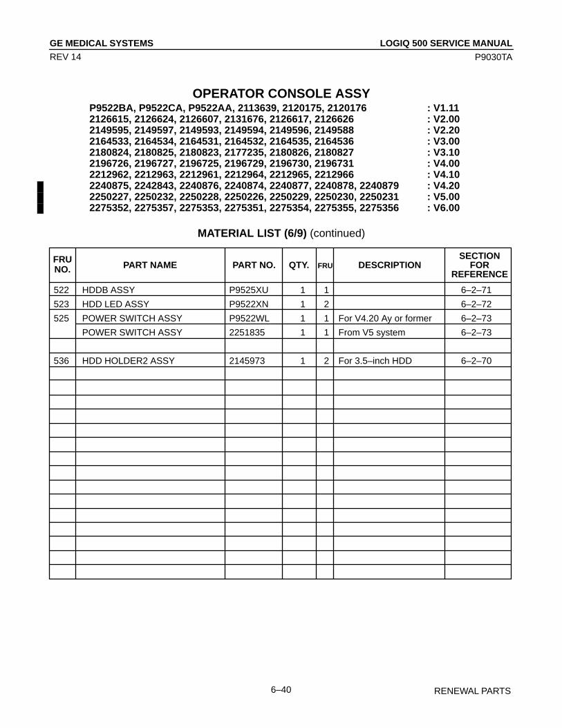
LOGIQ 500 SERVICE MANUALGE MEDICAL SYSTEMS
P9030TA
RENEWAL PARTS6–40
REV 14
OPERATOR CONSOLE ASSYP9522BA, P9522CA, P9522AA, 2113639, 2120175, 2120176 : V1.112126615, 2126624, 2126607, 2131676, 2126617, 2126626 : V2.002149595, 2149597, 2149593, 2149594, 2149596, 2149588 : V2.202164533, 2164534, 2164531, 2164532, 2164535, 2164536 : V3.002180824, 2180825, 2180823, 2177235, 2180826, 2180827 : V3.102196726, 2196727, 2196725, 2196729, 2196730, 2196731 : V4.002212962, 2212963, 2212961, 2212964, 2212965, 2212966 : V4.102240875, 2242843, 2240876, 2240874, 2240877, 2240878, 2240879 : V4.202250227, 2250232, 2250228, 2250226, 2250229, 2250230, 2250231 : V5.002275352, 2275357, 2275353, 2275351, 2275354, 2275355, 2275356 : V6.00
MATERIAL LIST (6/9) (continued)
SECTIONPART NAME PART NO. QTY. DESCRIPTION FOR
REFERENCE
522 HDDB ASSY P9525XU 1 1 6–2–71
523 HDD LED ASSY P9522XN 1 2 6–2–72
525 POWER SWITCH ASSY P9522WL 1 1 For V4.20 Ay or former 6–2–73
POWER SWITCH ASSY 2251835 1 1 From V5 system 6–2–73
536 HDD HOLDER2 ASSY 2145973 1 2 For 3.5–inch HDD 6–2–70
FRUNO. FRU

LOGIQ 500 SERVICE MANUALGE MEDICAL SYSTEMS
P9030TA
RENEWAL PARTS6–41
REV 14
OPERATOR CONSOLE ASSYP9522BA, P9522CA, P9522AA, 2113639, 2120175, 2120176 : V1.112126615, 2126624, 2126607, 2131676, 2126617, 2126626 : V2.002149595, 2149597, 2149593, 2149594, 2149596, 2149588 : V2.202164533, 2164534, 2164531, 2164532, 2164535, 2164536 : V3.002180824, 2180825, 2180823, 2177235, 2180826, 2180827 : V3.102196726, 2196727, 2196725, 2196729, 2196730, 2196731 : V4.002212962, 2212963, 2212961, 2212964, 2212965, 2212966 : V4.102240875, 2242843, 2240876, 2240874, 2240877, 2240878, 2240879 : V4.202250227, 2250232, 2250228, 2250226, 2250229, 2250230, 2250231 : V5.002275352, 2275357, 2275353, 2275351, 2275354, 2275355, 2275356 : V6.00
MATERIAL LIST (6/9) (continued)
SECTIONPART NAME PART NO. QTY. DESCRIPTION FOR
REFERENCE
526 FLAT CABLE CB91 P9522MV 1 1 HB16 to CONN 1
527 FLAT CABLE CB21 P9522ME 1 1 CONN 2 to Mother
528 FLAT CABLE CB22 P9522MG 1 1 ECG board to Mother
529 FLAT CABLE CB23 P9522MH 1 1 Keyboard to Mother
530 FLAT CABLE CB24 P9522MJ 1 1
531 FLAT CABLE CB29 P9522MN 1 1 REAR 2 to Mother
532 FLAT CABLE CB31 P9522MP 1 1 REAR 1 to Mother
533 FLAT CABLE CB32 P9522MQ 1 1 REAR 1 to Mother
534 FLAT CABLE CB24M 2122995 1 1
535 FLAT CABLE CB24N 2145889 1 1
537 CABLE CB45N 2145891 1 2
538 CABLE CB46 P9522NJ 1 2
550 CB6M CABLE 2122996 1 2 MODD – Mother
551 CB5 CABLE P9522MC 1 2 2.5–inch HDD – Mother
FRUNO. FRU
REAR 1 and MOTHER toMODD and 2.5–inch HDDFrom Ver.2.00 softwareconsole
MOTHER to HDDB to MODD to REAR Panel
MOTHER to 3.5–inch HDD to MODD
3.5–inch HDD to cable CB46 HDD LED
REAR 1 to FDDSoftware version 1.20or older console

LOGIQ 500 SERVICE MANUALGE MEDICAL SYSTEMS
P9030TA
RENEWAL PARTS6–42
REV 14
OPERATOR CONSOLE ASSYP9522BA, P9522CA, P9522AA, 2113639, 2120175, 2120176 : V1.112126615, 2126624, 2126607, 2131676, 2126617, 2126626 : V2.002149595, 2149597, 2149593, 2149594, 2149596, 2149588 : V2.202164533, 2164534, 2164531, 2164532, 2164535, 2164536 : V3.002180824, 2180825, 2180823, 2177235, 2180826, 2180827 : V3.102196726, 2196727, 2196725, 2196729, 2196730, 2196731 : V4.002212962, 2212963, 2212961, 2212964, 2212965, 2212966 : V4.102240875, 2242843, 2240876, 2240874, 2240877, 2240878, 2240879 : V4.202250227, 2250232, 2250228, 2250226, 2250229, 2250230, 2250231 : V5.002275352, 2275357, 2275353, 2275351, 2275354, 2275355, 2275356 : V6.00
MATERIAL LIST (6/9) (continued)
SECTIONPART NAME PART NO. QTY. DESCRIPTION FOR
REFERENCE
540 MODD U0052ZA 1 1 From Ver.2.00 software 6–2–74
console
MODD 2187012 1 1 Refer to Note below: 6–2–74
MODD 2187012–2 1 1 Refer to Note below: 6–2–74
MODD 2271309 1 1 6–2–74
541 MODD FAN ASSY 2122998–2 1 2 From Ver.2.00 software 6–2–74
console
542 MODD HOLDER ASSY 2117029–2 1 2 6–2–74
FRUNO. FRU
From Ver.2.00 softwareconsoleThis FRU includes MODDFAN (2122998)
New one (2271309) canbe replaced by Old one
NoteThe folding method of CB24M (or CB24N) cable is different between the case of using the old MODD(U0052ZA) and the case of using the new one (2187012 or 2187012–2). For more details regardingthe folding cable, refer to 6–6–4 on page 6–251.
NoteThree types of MODD (U0052ZA, 2187012, and 2187012–2) are used for the console. The appear-ance is different depending on the type of MODD. When replacing the MODD, make sure that thejumper switches and the DIP switches are set properly. Refer to the section 6–2–74 on page 6–172.

LOGIQ 500 SERVICE MANUALGE MEDICAL SYSTEMS
P9030TA
RENEWAL PARTS6–43
REV 14
OPERATOR CONSOLE ASSYP9522BA, P9522CA, P9522AA, 2113639, 2120175, 2120176 : V1.112126615, 2126624, 2126607, 2131676, 2126617, 2126626 : V2.002149595, 2149597, 2149593, 2149594, 2149596, 2149588 : V2.202164533, 2164534, 2164531, 2164532, 2164535, 2164536 : V3.002180824, 2180825, 2180823, 2177235, 2180826, 2180827 : V3.102196726, 2196727, 2196725, 2196729, 2196730, 2196731 : V4.002212962, 2212963, 2212961, 2212964, 2212965, 2212966 : V4.102240875, 2242843, 2240876, 2240874, 2240877, 2240878, 2240879 : V4.202250227, 2250232, 2250228, 2250226, 2250229, 2250230, 2250231 : V5.002275352, 2275357, 2275353, 2275351, 2275354, 2275355, 2275356 : V6.00
MATERIAL LIST (6/9) (continued)
SECTIONPART NAME PART NO. QTY. DESCRIPTION FOR
REFERENCE
580 HDD REPLACEMENT KIT 2160057 1 2
582 DCON ASSY 2123321 1 1
FRUNO. FRU
Including required partsto replace 2.5–inch HDDwith 3.5–inch HDD:HDD Holder2 Assy, threecables (CB24N, CB5N,CB45N), Tie Wrap, andInstructions
For Japanese A consolewith software version3.10 or later

LOGIQ 500 SERVICE MANUALGE MEDICAL SYSTEMS
P9030TA
RENEWAL PARTS6–44
REV 14
OPERATOR CONSOLE ASSY 7/9
614 Nest Mother Assy
606 TLMC Assy
607 DDSC AssyDDSC2 ASSYDDSC3 Assy
609 VIPB AssyVIPB2 ASSYVIPP ASSY
608 VIDO ASSYVIDO2 Assy
605B ACFP AssyACFP2 ASSYACFP3 ASSY
ILLUSTRATION 6–8
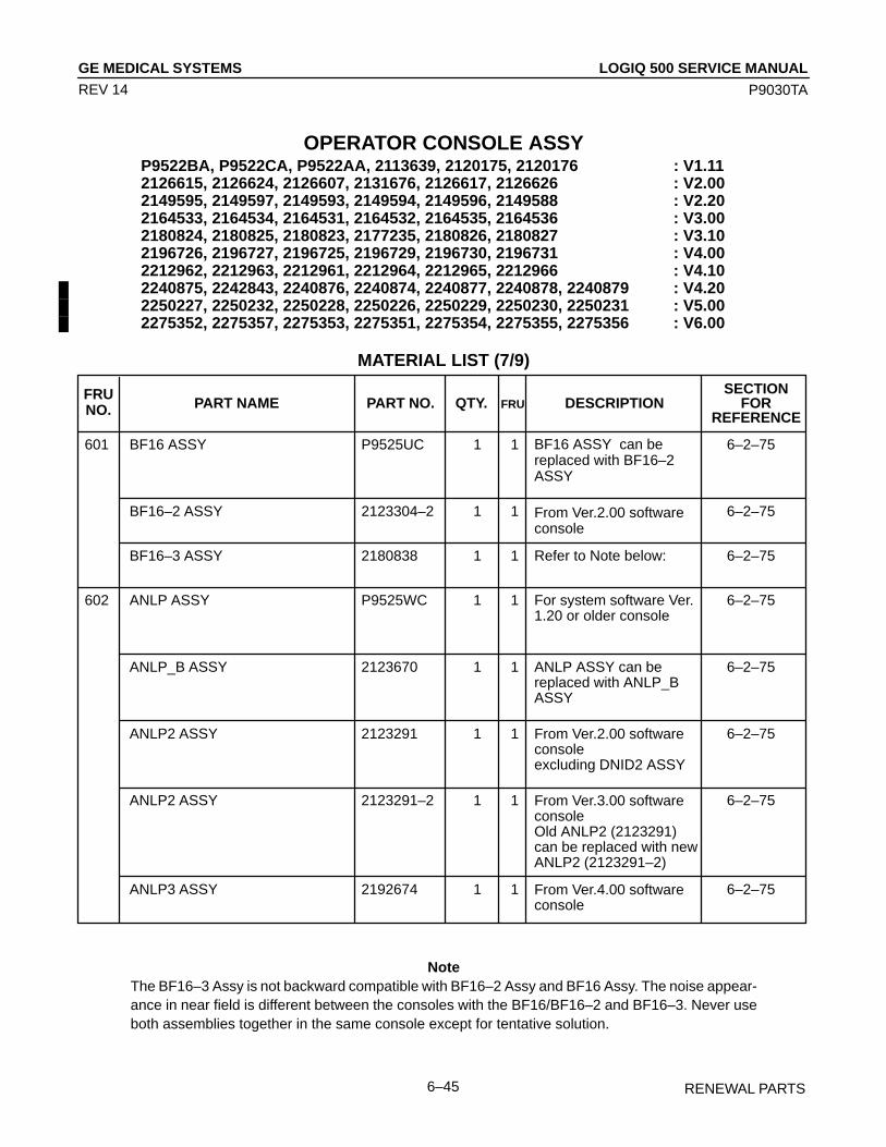
LOGIQ 500 SERVICE MANUALGE MEDICAL SYSTEMS
P9030TA
RENEWAL PARTS6–45
REV 14
OPERATOR CONSOLE ASSYP9522BA, P9522CA, P9522AA, 2113639, 2120175, 2120176 : V1.112126615, 2126624, 2126607, 2131676, 2126617, 2126626 : V2.002149595, 2149597, 2149593, 2149594, 2149596, 2149588 : V2.202164533, 2164534, 2164531, 2164532, 2164535, 2164536 : V3.002180824, 2180825, 2180823, 2177235, 2180826, 2180827 : V3.102196726, 2196727, 2196725, 2196729, 2196730, 2196731 : V4.002212962, 2212963, 2212961, 2212964, 2212965, 2212966 : V4.102240875, 2242843, 2240876, 2240874, 2240877, 2240878, 2240879 : V4.202250227, 2250232, 2250228, 2250226, 2250229, 2250230, 2250231 : V5.002275352, 2275357, 2275353, 2275351, 2275354, 2275355, 2275356 : V6.00
MATERIAL LIST (7/9)
SECTIONPART NAME PART NO. QTY. DESCRIPTION FOR
REFERENCE
601 BF16 ASSY P9525UC 1 1 6–2–75
BF16–2 ASSY 2123304–2 1 1 6–2–75
BF16–3 ASSY 2180838 1 1 6–2–75
602 ANLP ASSY P9525WC 1 1 6–2–75
ANLP_B ASSY 2123670 1 1 6–2–75
ANLP2 ASSY 2123291 1 1 6–2–75
ANLP2 ASSY 2123291–2 1 1 6–2–75
ANLP3 ASSY 2192674 1 1 6–2–75
FRUNO. FRU
BF16 ASSY can be replaced with BF16–2ASSY
For system software Ver.1.20 or older console
From Ver.2.00 softwareconsoleexcluding DNID2 ASSY
From Ver.2.00 softwareconsole
ANLP ASSY can bereplaced with ANLP_BASSY
From Ver.3.00 softwareconsoleOld ANLP2 (2123291) can be replaced with newANLP2 (2123291–2)
Refer to Note below:
From Ver.4.00 softwareconsole
NoteThe BF16–3 Assy is not backward compatible with BF16–2 Assy and BF16 Assy. The noise appear-ance in near field is different between the consoles with the BF16/BF16–2 and BF16–3. Never useboth assemblies together in the same console except for tentative solution.

LOGIQ 500 SERVICE MANUALGE MEDICAL SYSTEMS
P9030TA
RENEWAL PARTS6–46
REV 14
OPERATOR CONSOLE ASSYP9522BA, P9522CA, P9522AA, 2113639, 2120175, 2120176 : V1.112126615, 2126624, 2126607, 2131676, 2126617, 2126626 : V2.002149595, 2149597, 2149593, 2149594, 2149596, 2149588 : V2.202164533, 2164534, 2164531, 2164532, 2164535, 2164536 : V3.002180824, 2180825, 2180823, 2177235, 2180826, 2180827 : V3.102196726, 2196727, 2196725, 2196729, 2196730, 2196731 : V4.002212962, 2212963, 2212961, 2212964, 2212965, 2212966 : V4.102240875, 2242843, 2240876, 2240874, 2240877, 2240878, 2240879 : V4.202250227, 2250232, 2250228, 2250226, 2250229, 2250230, 2250231 : V5.002275352, 2275357, 2275353, 2275351, 2275354, 2275355, 2275356 : V6.00
MATERIAL LIST (7/9) (continued)
SECTIONPART NAME PART NO. QTY. DESCRIPTION FOR
REFERENCE
602 ANLP3 ASSY 2192674–2 1 1 6–2–75
ANLP3 ASSY 2192674–3 1 1 6–2–75
603 RCTL ASSY P9525WG 1 1 6–2–75
RCTL2 ASSY 2123300 1 1 6–2–75
RCTL2 ASSY 2180314 1 1 6–2–75
604 DIGP ASSY P9525WJ 1 1 6–2–75DIGP2 ASSY 2116900 1 1 6–2–75
DIGP3 ASSY 2123296 1 1 6–2–75
FRUNO. FRU
From Ver.2.00 softwareconsole
DIGP2 ASSY can be replaced with DIGP3ASSY
Required to use P509PROBE
RCTL ASSY can be replaced with RCTL2ASSY
From Ver.2.00 softwareconsole
Old ANLP3 (2192674) can be replaced with newANLP3 (2192674–2) ANLP3 (2192674–2) isrequired when optionalTHI is installed
Old ANLP3 (2192674) can be replaced with newANLP3 (2192674–3) ANLP3 (2192674–3) isrequired when optionalTHI is installed
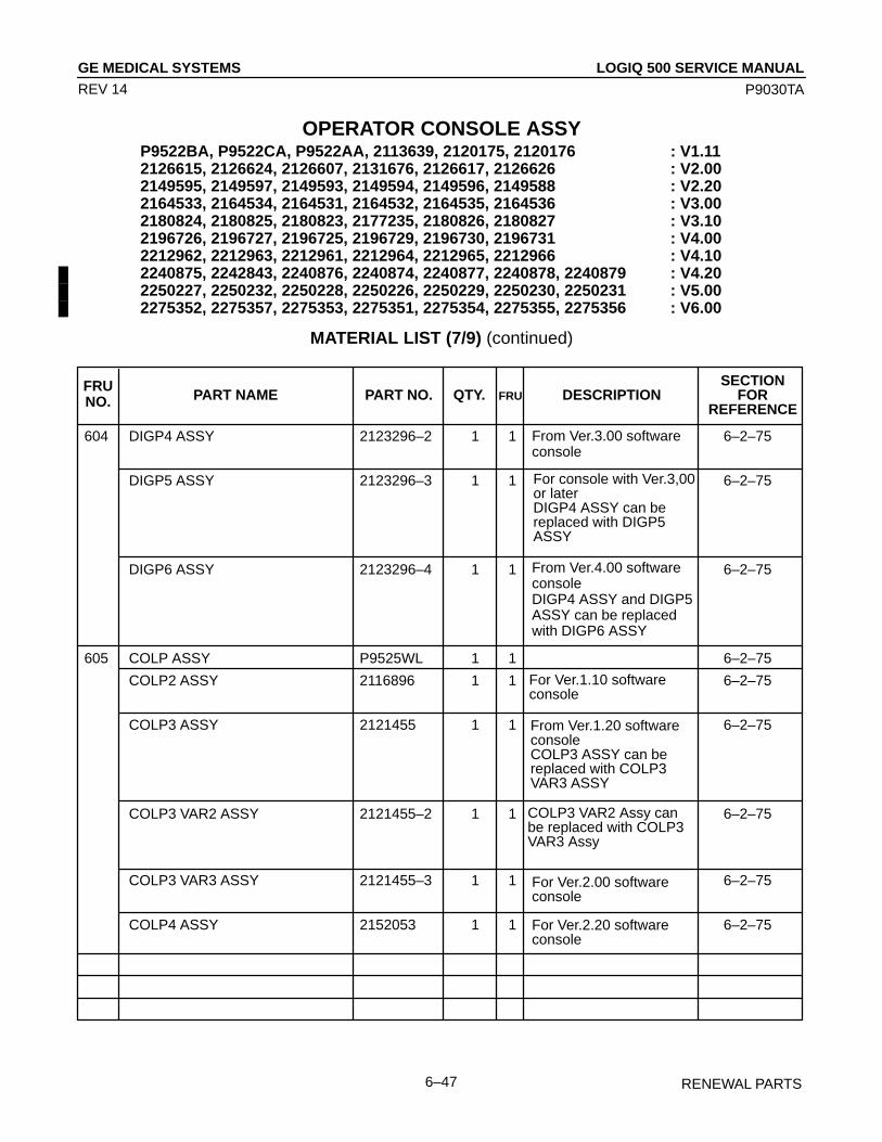
LOGIQ 500 SERVICE MANUALGE MEDICAL SYSTEMS
P9030TA
RENEWAL PARTS6–47
REV 14
OPERATOR CONSOLE ASSYP9522BA, P9522CA, P9522AA, 2113639, 2120175, 2120176 : V1.112126615, 2126624, 2126607, 2131676, 2126617, 2126626 : V2.002149595, 2149597, 2149593, 2149594, 2149596, 2149588 : V2.202164533, 2164534, 2164531, 2164532, 2164535, 2164536 : V3.002180824, 2180825, 2180823, 2177235, 2180826, 2180827 : V3.102196726, 2196727, 2196725, 2196729, 2196730, 2196731 : V4.002212962, 2212963, 2212961, 2212964, 2212965, 2212966 : V4.102240875, 2242843, 2240876, 2240874, 2240877, 2240878, 2240879 : V4.202250227, 2250232, 2250228, 2250226, 2250229, 2250230, 2250231 : V5.002275352, 2275357, 2275353, 2275351, 2275354, 2275355, 2275356 : V6.00
MATERIAL LIST (7/9) (continued)
SECTIONPART NAME PART NO. QTY. DESCRIPTION FOR
REFERENCE
604 DIGP4 ASSY 2123296–2 1 1 6–2–75
DIGP5 ASSY 2123296–3 1 1 6–2–75
DIGP6 ASSY 2123296–4 1 1 6–2–75
605 COLP ASSY P9525WL 1 1 6–2–75
COLP2 ASSY 2116896 1 1 6–2–75
COLP3 ASSY 2121455 1 1 6–2–75
COLP3 VAR2 ASSY 2121455–2 1 1 6–2–75
COLP3 VAR3 ASSY 2121455–3 1 1 6–2–75
COLP4 ASSY 2152053 1 1 6–2–75
FRUNO. FRU
For Ver.2.20 softwareconsole
COLP3 VAR2 Assy canbe replaced with COLP3VAR3 Assy
For Ver.2.00 softwareconsole
From Ver.1.20 softwareconsoleCOLP3 ASSY can bereplaced with COLP3VAR3 ASSY
For Ver.1.10 softwareconsole
From Ver.3.00 softwareconsole
For console with Ver.3,00or laterDIGP4 ASSY can bereplaced with DIGP5 ASSY
From Ver.4.00 softwareconsoleDIGP4 ASSY and DIGP5ASSY can be replaced with DIGP6 ASSY

LOGIQ 500 SERVICE MANUALGE MEDICAL SYSTEMS
P9030TA
RENEWAL PARTS6–48
REV 14
OPERATOR CONSOLE ASSYP9522BA, P9522CA, P9522AA, 2113639, 2120175, 2120176 : V1.112126615, 2126624, 2126607, 2131676, 2126617, 2126626 : V2.002149595, 2149597, 2149593, 2149594, 2149596, 2149588 : V2.202164533, 2164534, 2164531, 2164532, 2164535, 2164536 : V3.002180824, 2180825, 2180823, 2177235, 2180826, 2180827 : V3.102196726, 2196727, 2196725, 2196729, 2196730, 2196731 : V4.002212962, 2212963, 2212961, 2212964, 2212965, 2212966 : V4.102240875, 2242843, 2240876, 2240874, 2240877, 2240878, 2240879 : V4.202250227, 2250232, 2250228, 2250226, 2250229, 2250230, 2250231 : V5.002275352, 2275357, 2275353, 2275351, 2275354, 2275355, 2275356 : V6.00
MATERIAL LIST (7/9) (continued)
SECTIONPART NAME PART NO. QTY. DESCRIPTION FOR
REFERENCE
605B ACFP ASSY 2153228 1 1 6–2–75
ACFP2 ASSY 2192562–2 1 1 6–2–75
ACFP3 ASSY 2249191–2 1 1 6–2–75
606 TLMC ASSY P9525WY 1 1 excluding OMEM 6–2–75
TLMC ASSY 2158390–2 1 1 6–2–75
607 DDSC ASSY P9525WQ 1 1 For V1 console 6–2–75
DDSC2 ASSY 2141644–2 1 1 6–2–75
DDSC3 ASSY 2141644–3 1 1 6–2–75
608 VIDO ASSY P9525WW 1 1 For Japan 6–2–75
VIDO2 ASSY 2117032–2 1 1 For Japan 6–2–75
VIDO2 ASSY 2117032–3 1 1 For MVME147–010 6–2–75
FRUNO. FRU
From Ver.2.00 softwareconsole
For console with softwareVer.2.00 or laterDDSC2 ASSY can be re-placed with DDSC3 ASSY
ACFP ASSY is installedinstead of COLP ASSYfrom Ver.3.00 softwareconsole
From Ver.3.00 softwareconsoleOld TLMC (P9525WY and2158390) can be replacedwith new TLMC (2158390–2)
From Ver.4.00 softwareconsole
From Ver.5.00 softwareconsole

LOGIQ 500 SERVICE MANUALGE MEDICAL SYSTEMS
P9030TA
RENEWAL PARTS6–49
REV 14
OPERATOR CONSOLE ASSYP9522BA, P9522CA, P9522AA, 2113639, 2120175, 2120176 : V1.112126615, 2126624, 2126607, 2131676, 2126617, 2126626 : V2.002149595, 2149597, 2149593, 2149594, 2149596, 2149588 : V2.202164533, 2164534, 2164531, 2164532, 2164535, 2164536 : V3.002180824, 2180825, 2180823, 2177235, 2180826, 2180827 : V3.102196726, 2196727, 2196725, 2196729, 2196730, 2196731 : V4.002212962, 2212963, 2212961, 2212964, 2212965, 2212966 : V4.102240875, 2242843, 2240876, 2240874, 2240877, 2240878, 2240879 : V4.202250227, 2250232, 2250228, 2250226, 2250229, 2250230, 2250231 : V5.002275352, 2275357, 2275353, 2275351, 2275354, 2275355, 2275356 : V6.00
MATERIAL LIST (7/9) (continued)
SECTIONPART NAME PART NO. QTY. DESCRIPTION FOR
REFERENCE
609 VIPB ASSY P9525VA 1 1 6–2–75
VIPB ASSY 2149141 1 1 For MVME147–010 6–2–75
VIPB2 ASSY 2212616–2 1 1 6–2–75
609B VIPP ASSY 2245652 1 1 6–2–75
610 CPU ASSY P9525UA 1 1 6–2–75
CPU2 ASSY 2131698 1 1 6–2–75
CPU2 ASSY 2131698–2 1 1 6–2–75
CPU–A ASSY 2195754 1 1 6–2–75
CPU–A ASSY 2195754–3 1 1 6–2–75
CPU–A ASSY 2195754–4 1 1 From V5 System 6–2–75
FRUNO. FRU
For console with softwareVer.4.00 or later
From Ver.3.00 softwareconsoleOld CPU2 (2131698) canbe replaced with newCPU2 (2131698–2)
CPU ASSY can bereplaced with CPU2 ASSY
From Ver.2.00 softwareconsole
Available on console withsoftware version 4.10B orlater
Available on console withsoftware version 5.00y orlater
Old CPU–A Assy (2196754and 2196754–2) can be re-placed with new one(2195754–3)
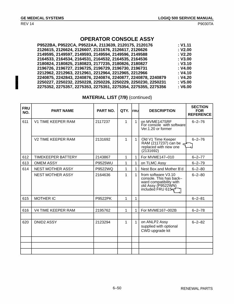
LOGIQ 500 SERVICE MANUALGE MEDICAL SYSTEMS
P9030TA
RENEWAL PARTS6–50
REV 14
OPERATOR CONSOLE ASSYP9522BA, P9522CA, P9522AA, 2113639, 2120175, 2120176 : V1.112126615, 2126624, 2126607, 2131676, 2126617, 2126626 : V2.002149595, 2149597, 2149593, 2149594, 2149596, 2149588 : V2.202164533, 2164534, 2164531, 2164532, 2164535, 2164536 : V3.002180824, 2180825, 2180823, 2177235, 2180826, 2180827 : V3.102196726, 2196727, 2196725, 2196729, 2196730, 2196731 : V4.002212962, 2212963, 2212961, 2212964, 2212965, 2212966 : V4.102240875, 2242843, 2240876, 2240874, 2240877, 2240878, 2240879 : V4.202250227, 2250232, 2250228, 2250226, 2250229, 2250230, 2250231 : V5.002275352, 2275357, 2275353, 2275351, 2275354, 2275355, 2275356 : V6.00
MATERIAL LIST (7/9) (continued)
SECTIONPART NAME PART NO. QTY. DESCRIPTION FOR
REFERENCE
611 V1 TIME KEEPER RAM 2117237 1 1 on MVME147SRF 6–2–76
V2 TIME KEEPER RAM 2131692 1 1 6–2–76
612 TIMEKEEPER BATTERY 2143867 1 1 For MVME147–010 6–2–77
613 OMEM ASSY P9525WU 1 1 on TLMC Assy 6–2–79
614 NEST MOTHER ASSY P9522WQ 1 1 Nest Box and Mother B’d 6–2–80
NEST MOTHER ASSY 2164636 1 1 6–2–80
615 MOTHER IC P9522PK 1 1 6–2–81
616 V4 TIME KEEPER RAM 2195762 1 1 For MVME167–002B 6–2–78
620 DNID2 ASSY 2123294 1 1 6–2–82
FRUNO. FRU
For console with softwareVer.1.20 or former
from software V3.10console. This has back–ward compatibility withold Assy (P9522WN)included FRU 615
on ANLP2 Assysupplied with optionalCWD upgrade kit
Old V1 Time KeeperRAM (2117237) can bereplaced with new one(2131692)
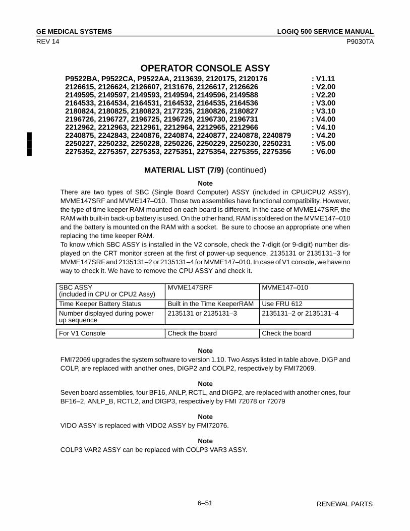
LOGIQ 500 SERVICE MANUALGE MEDICAL SYSTEMS
P9030TA
RENEWAL PARTS6–51
REV 14
OPERATOR CONSOLE ASSYP9522BA, P9522CA, P9522AA, 2113639, 2120175, 2120176 : V1.112126615, 2126624, 2126607, 2131676, 2126617, 2126626 : V2.002149595, 2149597, 2149593, 2149594, 2149596, 2149588 : V2.202164533, 2164534, 2164531, 2164532, 2164535, 2164536 : V3.002180824, 2180825, 2180823, 2177235, 2180826, 2180827 : V3.102196726, 2196727, 2196725, 2196729, 2196730, 2196731 : V4.002212962, 2212963, 2212961, 2212964, 2212965, 2212966 : V4.102240875, 2242843, 2240876, 2240874, 2240877, 2240878, 2240879 : V4.202250227, 2250232, 2250228, 2250226, 2250229, 2250230, 2250231 : V5.002275352, 2275357, 2275353, 2275351, 2275354, 2275355, 2275356 : V6.00
MATERIAL LIST (7/9) (continued)
NoteThere are two types of SBC (Single Board Computer) ASSY (included in CPU/CPU2 ASSY),MVME147SRF and MVME147–010. Those two assemblies have functional compatibility. However,the type of time keeper RAM mounted on each board is different. In the case of MVME147SRF, theRAM with built-in back-up battery is used. On the other hand, RAM is soldered on the MVME147–010and the battery is mounted on the RAM with a socket. Be sure to choose an appropriate one whenreplacing the time keeper RAM.To know which SBC ASSY is installed in the V2 console, check the 7-digit (or 9-digit) number dis-played on the CRT monitor screen at the first of power-up sequence, 2135131 or 2135131–3 forMVME147SRF and 2135131–2 or 2135131–4 for MVME147–010. In case of V1 console, we have noway to check it. We have to remove the CPU ASSY and check it.
SBC ASSY MVME147SRF MVME147–010(included in CPU or CPU2 Assy)Time Keeper Battery Status Built in the Time KeeperRAM Use FRU 612Number displayed during power 2135131 or 2135131–3 2135131–2 or 2135131–4up sequence
For V1 Console Check the board Check the board
NoteFMI72069 upgrades the system software to version 1.10. Two Assys listed in table above, DIGP andCOLP, are replaced with another ones, DIGP2 and COLP2, respectively by FMI72069.
NoteSeven board assemblies, four BF16, ANLP, RCTL, and DIGP2, are replaced with another ones, fourBF16–2, ANLP_B, RCTL2, and DIGP3, respectively by FMI 72078 or 72079
NoteVIDO ASSY is replaced with VIDO2 ASSY by FMI72076.
NoteCOLP3 VAR2 ASSY can be replaced with COLP3 VAR3 ASSY.

LOGIQ 500 SERVICE MANUALGE MEDICAL SYSTEMS
P9030TA
RENEWAL PARTS6–52
REV 14
OPERATOR CONSOLE ASSYP9522BA, P9522CA, P9522AA, 2113639, 2120175, 2120176 : V1.112126615, 2126624, 2126607, 2131676, 2126617, 2126626 : V2.002149595, 2149597, 2149593, 2149594, 2149596, 2149588 : V2.202164533, 2164534, 2164531, 2164532, 2164535, 2164536 : V3.002180824, 2180825, 2180823, 2177235, 2180826, 2180827 : V3.102196726, 2196727, 2196725, 2196729, 2196730, 2196731 : V4.002212962, 2212963, 2212961, 2212964, 2212965, 2212966 : V4.102240875, 2242843, 2240876, 2240874, 2240877, 2240878, 2240879 : V4.202250227, 2250232, 2250228, 2250226, 2250229, 2250230, 2250231 : V5.002275352, 2275357, 2275353, 2275351, 2275354, 2275355, 2275356 : V6.00
MATERIAL LIST (7/9) (continued)
NoteDDSC ASSY and DDSC2 ASSY have no compatibility. Each assembly has been replaced with equiv-alent one, respectively. DDSC ASSY should be used only for V1 console and DDSC2 ASSY should beused only for V2 console.
NoteTLMC ASSY is changed with a backward compatibility from the console with software version 3.00.With this change, the part number of TLMC ASSY is changed to 2158390 from P9525WY.
NoteVIDO2 ASSY and VIPB ASSY are changed with the backward compatibility to correspond to the newSBC ASSY, MVME147–010. With this changes, the part numbers of VIDO2 ASSY and VIPB ASSYare changed to 2117032–3 and 2149141 from 2117032–2 and P9525VA, respectively. Be sure to usethe new Video board to replace the VIDO2 or VIPB ASSY installed in the console with the CPU2 ASSYincluding the new SBC ASSY, MVME147–010.
NoteDIGP4 Assy has backward compatibility with DIGP3 Assy. DIGP3 ASSY can be replaced with DIGP4ASSY.
NoteTo install the VIPB2 Assy (2212616) in the console, the CPU–A Assy has to be installed in the consoleand the software version has to be 4.10By or later.

LOGIQ 500 SERVICE MANUALGE MEDICAL SYSTEMS
P9030TA
RENEWAL PARTS6–53
REV 14
This page is left blank intentionally.

LOGIQ 500 SERVICE MANUALGE MEDICAL SYSTEMS
P9030TA
RENEWAL PARTS6–54
REV 14
OPERATOR CONSOLE ASSY 8/9
ILLUSTRATION 6–9

LOGIQ 500 SERVICE MANUALGE MEDICAL SYSTEMS
P9030TA
RENEWAL PARTS6–55
REV 14
OPERATOR CONSOLE ASSYP9522BA, P9522CA, P9522AA, 2113639, 2120175, 2120176 : V1.112126615, 2126624, 2126607, 2131676, 2126617, 2126626 : V2.002149595, 2149597, 2149593, 2149594, 2149596, 2149588 : V2.202164533, 2164534, 2164531, 2164532, 2164535, 2164536 : V3.002180824, 2180825, 2180823, 2177235, 2180826, 2180827 : V3.102196726, 2196727, 2196725, 2196729, 2196730, 2196731 : V4.002212962, 2212963, 2212961, 2212964, 2212965, 2212966 : V4.102240875, 2242843, 2240876, 2240874, 2240877, 2240878, 2240879 : V4.202250227, 2250232, 2250228, 2250226, 2250229, 2250230, 2250231 : V5.002275352, 2275357, 2275353, 2275351, 2275354, 2275355, 2275356 : V6.00
MATERIAL LIST (8/9)
SECTIONPART NAME PART NO. QTY. DESCRIPTION FOR
REFERENCE
701 A1 PS +5V 32A P9522QA 1 1 For 100/120V console 6–2–83
A1 PS +5V 32A P9522RA 1 1 For 220V console 6–2–83
702 A2 PS –5.2V 11A P9522QB 1 1 For 100/120V console 6–2–84
A2 PS –5.2V 11A P9522RB 1 1 For 220V console 6–2–84
703 A3 PS +12V 8.4A P9522QC 1 1 For 100/120V console 6–2–85
A3 PS +12V 8.4A P9522RC 1 1 For 220V console 6–2–85
704 A4 PS –12V 2.5A P9522QD 1 1 6–2–86
705 A5 PS +5V 30A P9522QE 1 1 For 100/120V console 6–2–87
A5 PS +5V 30A P9522RE 1 1 For 220V console 6–2–87
706 A7 SW CONT ASSY P9522QF 1 1 6–2–88
707 A8 PFC ASSY P9522QG 1 1 6–2–89
708 A10 HV REG ASSY P9522QH 1 1 6–2–90
709 RL1 & 2 ASSY P9522QJ 1 1 6–2–91
710 RL3 P9522QK 1 1 6–2–92
711 PRIMARY TRANS P9522QL 1 1
712 HV TRANS P9522QM 1 1
713 PS FAN SET P9522QN 1 1 6–2–93
714 BREAKER 20A P9522QP 1 1 For 100/120V console 6–2–94
715 BREAKER 7.5A P9522QQ 1 1 For 220V console 6–2–94
717 POWER SUPPLY AC 120V P9523DB 1 2 6–5
718 POWER SUPPLY AC 220V P9523DA 1 2 6–5
720 INLET UNIT 120V 2220699 1 2 For 120V console 6–2–95
INLET UNIT 220V 2220700 1 2 For 220V console 6–2–95
721 INRUSH LIMITER 120V 2220701 1 2 For 120V console 6–2–96
INRUSH LIMITER 220V 2220702 1 2 For 220V console 6–2–96
FRUNO. FRU
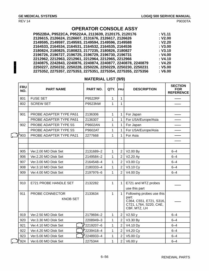
LOGIQ 500 SERVICE MANUALGE MEDICAL SYSTEMS
P9030TA
RENEWAL PARTS6–56
REV 14
OPERATOR CONSOLE ASSYP9522BA, P9522CA, P9522AA, 2113639, 2120175, 2120176 : V1.112126615, 2126624, 2126607, 2131676, 2126617, 2126626 : V2.002149595, 2149597, 2149593, 2149594, 2149596, 2149588 : V2.202164533, 2164534, 2164531, 2164532, 2164535, 2164536 : V3.002180824, 2180825, 2180823, 2177235, 2180826, 2180827 : V3.102196726, 2196727, 2196725, 2196729, 2196730, 2196731 : V4.002212962, 2212963, 2212961, 2212964, 2212965, 2212966 : V4.102240875, 2242843, 2240876, 2240874, 2240877, 2240878, 2240879 : V4.202250227, 2250232, 2250228, 2250226, 2250229, 2250230, 2250231 : V5.002275352, 2275357, 2275353, 2275351, 2275354, 2275355, 2275356 : V6.00
MATERIAL LIST (9/9)
SECTIONPART NAME PART NO. QTY. DESCRIPTION FOR
REFERENCE
801 FUSE SET P9522RF 1 1
802 SCREW SET P9523NW 1 1
901 PROBE ADAPTER TYPE PA51 2136306 1 1 For Japan
PROBE ADAPTER TYPE PA51 2136307 1 1 For USA/Europe/Asia
902 PROBE ADAPTER TYPE 5S P9602AN 1 1 For Japan
PROBE ADAPTER TYPE 5S P9602AT 1 1 For USA/Europe/Asia
903 PROBE ADAPTER TYPE PA21 2277668 1 1 For Asia
905 Ver.2.00 MO Disk Set 2131689–2 1 2 V2.00 By 6–4
906 Ver.2.20 MO Disk Set 2149584–2 1 2 V2.20 Ay 6–4
907 Ver.3.00 MO Disk Set 2164548–4 1 2 V3.00 Cy 6–4
908 Ver.3.10 MO Disk Set 2180333–4 1 2 V3.10 Cy 6–4
909 Ver.4.00 MO Disk Set 2197976–6 1 2 V4.00 Dy 6–4
910 E721 PROBE HANDLE SET 2132282 1 1 E721 and MTZ probes
use this part
911 PROBE CONNECTOR 2133634 1 1
KNOB SET
919 Ver.2.50 MO Disk Set 2179694–2 1 2 V2.50 y 6–4
920 Ver.3.30 MO Disk Set 2208949–3 1 2 V3.30 By 6–4
921 Ver.4.10 MO Disk Set 2219207–6 1 2 V4.10 Dy 6–4
922 Ver.4.20 MO Disk Set 2239418–4 1 2 V4.20 Cy 6–4
923 Ver.5.00 MO Disk Set 2248933–4 1 2 V5.00 Cy 6–4
924 Ver.6.00 MO Disk Set 2275344 1 2 V6.00 y 6–4
FRUNO. FRU
Following probes use thispart:C364, C551, E721, S316,C721, L764, S220, CAE,CBF, MTZ, LH
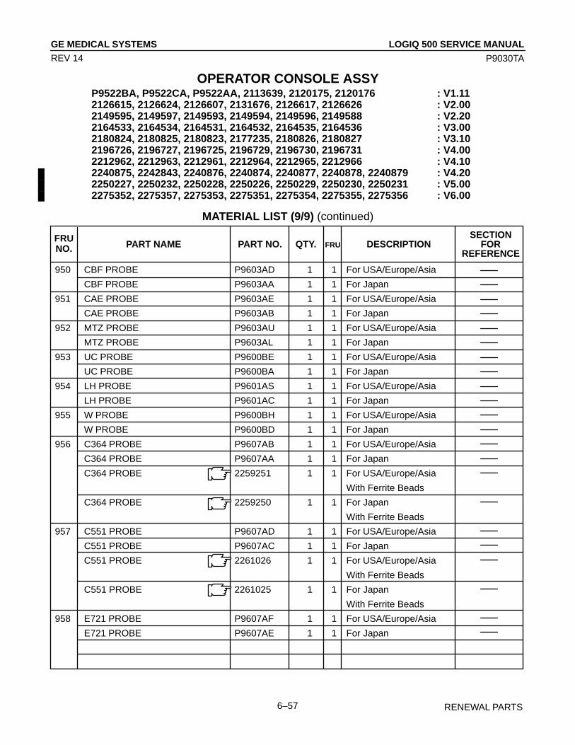
LOGIQ 500 SERVICE MANUALGE MEDICAL SYSTEMS
P9030TA
RENEWAL PARTS6–57
REV 14
OPERATOR CONSOLE ASSYP9522BA, P9522CA, P9522AA, 2113639, 2120175, 2120176 : V1.112126615, 2126624, 2126607, 2131676, 2126617, 2126626 : V2.002149595, 2149597, 2149593, 2149594, 2149596, 2149588 : V2.202164533, 2164534, 2164531, 2164532, 2164535, 2164536 : V3.002180824, 2180825, 2180823, 2177235, 2180826, 2180827 : V3.102196726, 2196727, 2196725, 2196729, 2196730, 2196731 : V4.002212962, 2212963, 2212961, 2212964, 2212965, 2212966 : V4.102240875, 2242843, 2240876, 2240874, 2240877, 2240878, 2240879 : V4.202250227, 2250232, 2250228, 2250226, 2250229, 2250230, 2250231 : V5.002275352, 2275357, 2275353, 2275351, 2275354, 2275355, 2275356 : V6.00
MATERIAL LIST (9/9) (continued)
SECTIONPART NAME PART NO. QTY. DESCRIPTION FOR
REFERENCE
950 CBF PROBE P9603AD 1 1 For USA/Europe/Asia
CBF PROBE P9603AA 1 1 For Japan
951 CAE PROBE P9603AE 1 1 For USA/Europe/Asia
CAE PROBE P9603AB 1 1 For Japan
952 MTZ PROBE P9603AU 1 1 For USA/Europe/Asia
MTZ PROBE P9603AL 1 1 For Japan
953 UC PROBE P9600BE 1 1 For USA/Europe/Asia
UC PROBE P9600BA 1 1 For Japan
954 LH PROBE P9601AS 1 1 For USA/Europe/Asia
LH PROBE P9601AC 1 1 For Japan
955 W PROBE P9600BH 1 1 For USA/Europe/Asia
W PROBE P9600BD 1 1 For Japan
956 C364 PROBE P9607AB 1 1 For USA/Europe/Asia
C364 PROBE P9607AA 1 1 For Japan
C364 PROBE 2259251 1 1 For USA/Europe/Asia
With Ferrite Beads
C364 PROBE 2259250 1 1 For Japan
With Ferrite Beads
957 C551 PROBE P9607AD 1 1 For USA/Europe/Asia
C551 PROBE P9607AC 1 1 For Japan
C551 PROBE 2261026 1 1 For USA/Europe/Asia
With Ferrite Beads
C551 PROBE 2261025 1 1 For Japan
With Ferrite Beads
958 E721 PROBE P9607AF 1 1 For USA/Europe/Asia
E721 PROBE P9607AE 1 1 For Japan
FRUNO. FRU

LOGIQ 500 SERVICE MANUALGE MEDICAL SYSTEMS
P9030TA
RENEWAL PARTS6–58
REV 14
OPERATOR CONSOLE ASSYP9522BA, P9522CA, P9522AA, 2113639, 2120175, 2120176 : V1.112126615, 2126624, 2126607, 2131676, 2126617, 2126626 : V2.002149595, 2149597, 2149593, 2149594, 2149596, 2149588 : V2.202164533, 2164534, 2164531, 2164532, 2164535, 2164536 : V3.002180824, 2180825, 2180823, 2177235, 2180826, 2180827 : V3.102196726, 2196727, 2196725, 2196729, 2196730, 2196731 : V4.002212962, 2212963, 2212961, 2212964, 2212965, 2212966 : V4.102240875, 2242843, 2240876, 2240874, 2240877, 2240878, 2240879 : V4.202250227, 2250232, 2250228, 2250226, 2250229, 2250230, 2250231 : V5.002275352, 2275357, 2275353, 2275351, 2275354, 2275355, 2275356 : V6.00
MATERIAL LIST (9/9) (continued)
SECTIONPART NAME PART NO. QTY. DESCRIPTION FOR
REFERENCE
958 E721 PROBE 2261056 1 1 For USA/Europe/Asia
With Ferrite Beads
E721 PROBE 2261055 1 1 For Japan
With Ferrite Beads
959 739L PROBE 2107460–2 1 1 For USA/Europe/Asia
739L PROBE 2107460 1 1 For Japan
739L PROBE 2259145 1 1 For USA/Europe/Asia
With Ferrite Beads
739L PROBE 2259144 1 1 For Japan
With Ferrite Beads
960 S316 PROBE P9606AB 1 1 For USA/Europe/Asia
S316 PROBE P9606AA 1 1 For Japan
S316 PROBE 2261033 1 1 For USA/Europe/Asia
With Ferrite Beads
S316 PROBE 2261032 1 1 For Japan
With Ferrite Beads
961 L764 PROBE 2121377–2 1 1 For USA/Europe/Asia
L764 PROBE 2121377 1 1 For Japan
L764 PROBE 2259256 1 1 For USA/Europe/Asia
With Ferrite Beads
L764 PROBE 2259255 1 1 For Japan
With Ferrite Beads
962 C721 PROBE 2121267–2 1 1 For USA/Europe/Asia
C721 PROBE 2121267 1 1 For Japan
C721 PROBE 2261018 1 1 For USA/Europe/Asia
With Ferrite Beads
C721 PROBE 2261017 1 1 For Japan
With Ferrite Beads
FRUNO. FRU

LOGIQ 500 SERVICE MANUALGE MEDICAL SYSTEMS
P9030TA
RENEWAL PARTS6–59
REV 14
OPERATOR CONSOLE ASSYP9522BA, P9522CA, P9522AA, 2113639, 2120175, 2120176 : V1.112126615, 2126624, 2126607, 2131676, 2126617, 2126626 : V2.002149595, 2149597, 2149593, 2149594, 2149596, 2149588 : V2.202164533, 2164534, 2164531, 2164532, 2164535, 2164536 : V3.002180824, 2180825, 2180823, 2177235, 2180826, 2180827 : V3.102196726, 2196727, 2196725, 2196729, 2196730, 2196731 : V4.002212962, 2212963, 2212961, 2212964, 2212965, 2212966 : V4.102240875, 2242843, 2240876, 2240874, 2240877, 2240878, 2240879 : V4.202250227, 2250232, 2250228, 2250226, 2250229, 2250230, 2250231 : V5.002275352, 2275357, 2275353, 2275351, 2275354, 2275355, 2275356 : V6.00
MATERIAL LIST (9/9) (continued)
SECTIONPART NAME PART NO. QTY. DESCRIPTION FOR
REFERENCE
963 B510 PROBE 2123593 1 1 For USA/Europe/Asia
B510 PROBE 2133115 1 1 For Japan
B510 PROBE 2259260 1 1 For USA/Europe/Asia
With Ferrite Beads
B510 PROBE 2259259 1 1 For Japan
With Ferrite Beads
964 S220 PROBE 2121793–2 1 1 For USA/Europe/Asia
S220 PROBE 2121793 1 1 For Japan
S220 PROBE 2261043 1 1 For USA/Europe/Asia
With Ferrite Beads
S220 PROBE 2261042 1 1 For Japan
With Ferrite Beads
970 CWD2 PROBE 2123594 1 1 For USA/Europe/Asia
CWD2 PROBE 2133116 1 1 For Japan
971 CWD5 PROBE 2123595 1 1 For USA/Europe/Asia
CWD5 PROBE 2133117 1 1 For Japan
973 546L PROBE 2144266–2 1 1 For USA/Europe/Asia
546L PROBE 2144266 1 1 For Japan
546L PROBE 2259135 1 1 For USA/Europe/Asia
With Ferrite Beads
546L PROBE 2259134 1 1 For Japan
With Ferrite Beads
974 S317 PROBE 2144268–2 1 1 For USA/Europe/Asia
S317 PROBE 2144268 1 1 For Japan
FRUNO. FRU

LOGIQ 500 SERVICE MANUALGE MEDICAL SYSTEMS
P9030TA
RENEWAL PARTS6–60
REV 14
OPERATOR CONSOLE ASSYP9522BA, P9522CA, P9522AA, 2113639, 2120175, 2120176 : V1.112126615, 2126624, 2126607, 2131676, 2126617, 2126626 : V2.002149595, 2149597, 2149593, 2149594, 2149596, 2149588 : V2.202164533, 2164534, 2164531, 2164532, 2164535, 2164536 : V3.002180824, 2180825, 2180823, 2177235, 2180826, 2180827 : V3.102196726, 2196727, 2196725, 2196729, 2196730, 2196731 : V4.002212962, 2212963, 2212961, 2212964, 2212965, 2212966 : V4.102240875, 2242843, 2240876, 2240874, 2240877, 2240878, 2240879 : V4.202250227, 2250232, 2250228, 2250226, 2250229, 2250230, 2250231 : V5.002275352, 2275357, 2275353, 2275351, 2275354, 2275355, 2275356 : V6.00
MATERIAL LIST (9/9) (continued)
SECTIONPART NAME PART NO. QTY. DESCRIPTION FOR
REFERENCE
974 S317 PROBE 2259230 1 1 For USA/Europe/Asia
With Ferrite Beads
S317 PROBE 2259229 1 1 For Japan
With Ferrite Beads
975 S611 PROBE 2144267–2 1 1 For USA/Europe/Asia
S611 PROBE 2144267 1 1 For Japan
S611 PROBE 2259238 1 1 For USA/Europe/Asia
With Ferrite Beads
S611 PROBE 2259237 1 1 For Japan
With Ferrite Beads
976 C386 PROBE 2154186–2 1 1 For USA/Europe/Asia
C386 PROBE 2154186 1 1 For Japan
C386 PROBE 2259162 1 1 For USA/Europe/Asia
With Ferrite Beads
C386 PROBE 2259160 1 1 For Japan
With Ferrite Beads
977 I739 PROBE 2147189–2 1 1 For USA/Europe/Asia
I739 PROBE 2147289 1 1 For Japan
I739 PROBE 2259206 1 1 For USA/Europe/Asia
With Ferrite Beads
I739 PROBE 2259205 1 1 For Japan
With Ferrite Beads
978 T739 PROBE 2147188–2 1 1 For USA/Europe/Asia
T739 PROBE 2147188 1 1 For Japan
T739 PROBE 2259246 1 1 For USA/Europe/Asia
With Ferrite Beads
T739 PROBE 2259245 1 1 For Japan
With Ferrite Beads
FRUNO. FRU

LOGIQ 500 SERVICE MANUALGE MEDICAL SYSTEMS
P9030TA
RENEWAL PARTS6–61
REV 14
OPERATOR CONSOLE ASSYP9522BA, P9522CA, P9522AA, 2113639, 2120175, 2120176 : V1.112126615, 2126624, 2126607, 2131676, 2126617, 2126626 : V2.002149595, 2149597, 2149593, 2149594, 2149596, 2149588 : V2.202164533, 2164534, 2164531, 2164532, 2164535, 2164536 : V3.002180824, 2180825, 2180823, 2177235, 2180826, 2180827 : V3.102196726, 2196727, 2196725, 2196729, 2196730, 2196731 : V4.002212962, 2212963, 2212961, 2212964, 2212965, 2212966 : V4.102240875, 2242843, 2240876, 2240874, 2240877, 2240878, 2240879 : V4.202250227, 2250232, 2250228, 2250226, 2250229, 2250230, 2250231 : V5.002275352, 2275357, 2275353, 2275351, 2275354, 2275355, 2275356 : V6.00
MATERIAL LIST (9/9) (continued)
SECTIONPART NAME PART NO. QTY. DESCRIPTION FOR
REFERENCE
979 LA39 PROBE 2155078–2 1 1 For USA/Europe/Asia
LA39 PROBE 2155078 1 1 For Japan
LA39 PROBE 2259214 1 1 For USA/Europe/Asia
With Ferrite Beads
LA39 PROBE 2259213 1 1 For Japan
With Ferrite Beads
980 S222 PROBE 2159263 1 1 For USA/Europe/Asia
S222 PROBE 2159263 1 1 For Japan
S222 PROBE 2259222 1 1 For USA/Europe/Asia
With Ferrite Beads
S222 PROBE 2259221 1 1 For Japan
With Ferrite Beads
981 P509 PROBE 2169773 1 1 For Europe/Asia
P509 PROBE 2169772 1 1 For Japan
P509 PROBE 2259258 1 1 For Europe/Asia
With Ferrite Beads
P509 PROBE 2259257 1 1 For Japan
With Ferrite Beads
982 C358 PROBE 2193617 1 1 For USA/Europe/Asia
C358 PROBE 2172443 1 1 For Japan
C358 PROBE 2259153 1 1 For USA/Europe/Asia
With Ferrite Beads
C358 PROBE 2259152 1 1 For Japan
With Ferrite Beads
983 LD PROBE 2124318 1 1 For Europe
LD PROBE P9601AD 1 1 For Japan
FRUNO. FRU

LOGIQ 500 SERVICE MANUALGE MEDICAL SYSTEMS
P9030TA
RENEWAL PARTS6–62
REV 14
OPERATOR CONSOLE ASSYP9522BA, P9522CA, P9522AA, 2113639, 2120175, 2120176 : V1.112126615, 2126624, 2126607, 2131676, 2126617, 2126626 : V2.002149595, 2149597, 2149593, 2149594, 2149596, 2149588 : V2.202164533, 2164534, 2164531, 2164532, 2164535, 2164536 : V3.002180824, 2180825, 2180823, 2177235, 2180826, 2180827 : V3.102196726, 2196727, 2196725, 2196729, 2196730, 2196731 : V4.002212962, 2212963, 2212961, 2212964, 2212965, 2212966 : V4.102240875, 2242843, 2240876, 2240874, 2240877, 2240878, 2240879 : V4.202250227, 2250232, 2250228, 2250226, 2250229, 2250230, 2250231 : V5.002275352, 2275357, 2275353, 2275351, 2275354, 2275355, 2275356 : V6.00
MATERIAL LIST (9/9) (continued)
SECTIONPART NAME PART NO. QTY. DESCRIPTION FOR
REFERENCE
983 LD PROBE 2261049 1 1 For Europe
With Ferrite Beads
LD PROBE 2261048 1 1 For Japan
With Ferrite Beads
984 ERB7 PROBE 2239590 1 1 For USA/Europe/Asia
ERB7 PROBE 2204232 1 1 For Japan
ERB7 PROBE 2259263 1 1 For USA/Europe/Asia
With Ferrite Beads
ERB7 PROBE 2259262 1 1 For Japan
With Ferrite Beads
985 M12L PROBE 2236016 1 1 For USA/Europe/Asia
With Ferrite Beads
M12L PROBE 2241735 1 1 For Japan
With Ferrite Beads
986 3S PROBE 2252157 1 1 For USA/Europe/Asia
With Ferrite Beads
3S PROBE 2261743 1 1 For Japan
With Ferrite Beads
988 CS PROBE 2202320 1 1 For Asia
With Ferrite Beads
989 i12L PROBE 2264883 1 1 For USA/Europe/Asia
With Ferrite Beads
i12L PROBE 2270556 1 1 For Japan
With Ferrite Beads
FRUNO. FRU

LOGIQ 500 SERVICE MANUALGE MEDICAL SYSTEMS
P9030TA
RENEWAL PARTS6–63
REV 14
OPERATOR CONSOLE ASSYP9522BA, P9522CA, P9522AA, 2113639, 2120175, 2120176 : V1.112126615, 2126624, 2126607, 2131676, 2126617, 2126626 : V2.002149595, 2149597, 2149593, 2149594, 2149596, 2149588 : V2.202164533, 2164534, 2164531, 2164532, 2164535, 2164536 : V3.002180824, 2180825, 2180823, 2177235, 2180826, 2180827 : V3.102196726, 2196727, 2196725, 2196729, 2196730, 2196731 : V4.002212962, 2212963, 2212961, 2212964, 2212965, 2212966 : V4.102240875, 2242843, 2240876, 2240874, 2240877, 2240878, 2240879 : V4.202250227, 2250232, 2250228, 2250226, 2250229, 2250230, 2250231 : V5.002275352, 2275357, 2275353, 2275351, 2275354, 2275355, 2275356 : V6.00
MATERIAL LIST (9/9) (continued)
SECTIONPART NAME PART NO. QTY. DESCRIPTION FOR
REFERENCE
995 10BASE–2 MAU 2195663 1 1
996 10BASE–T MAU 2195664 1 1
997 ETHERNET CABLE 2195662 1 2
FRUNO. FRU

LOGIQ 500 SERVICE MANUALGE MEDICAL SYSTEMS
P9030TA
RENEWAL PARTS6–64
REV 14
This page is left blank intentionally.

LOGIQ 500 SERVICE MANUALGE MEDICAL SYSTEMS
P9030TA
RENEWAL PARTS6–65
REV 14
6–2 DISASSEMBLY/RE–ASSEMBLY
WARNING!
ONLY QUALIFIED SERVICE PERSONNEL SHOULD REMOVE ANY COVERS OR PANELS.ELECTRICAL HAZARDS EXISTS AT SEVERAL POINTS INSIDE. BECOME THOROUGHLY FA-MILIAR WITH ALL HAZARDOUS VOLTAGES AND HIGH CURRENT LEVELS TO AVOID ACCI-DENTAL CONTACT
CAUTION
Do not wear the ESD wrist strap when you remove a part of power supply unit. Turn OFF powerand unplug the power cord before removing a part of power supply unit. However be sure toturn off power and wear the strap before you remove a circuit boards.

LOGIQ 500 SERVICE MANUALGE MEDICAL SYSTEMS
P9030TA
RENEWAL PARTS6–66
REV 14
6–2–1 Monitor Assy (FRU No. 100)
Time Required
0.25 Hours
Tool Required
ScrewdriverHexagonal Wrench
Procedure
WARNING!
PERSONAL INJURY HAZARD. VIDEO MONITOR SUPPORT ARM IS SPRING LOADED. RE-LEASING ARM WHEN MONITOR IS NOT INSTALLED WILL CAUSE SUDDEN UPWARD MOVE-MENT. KEEP YOUR HEAD AND BODY AWAY FROM ABOVE VIDEO MONITOR SUPPORT ARM.
Refer to ILLUSTRATION 6–10 on page 6–67.
1. Turn OFF the system.
2. Remove the CRT Filter. Refer to 6–2–6 on page 6–75.
3. Unscrew four hexagonal screws ( 1 – 4 ) located beneath the horizontal part of the Neck Assy.
4. Remove the cover located at the bottom of the Neck Assy.
5. Unscrew two screws ( 5 and 6 ) and remove the plate fixing the cables.
6. Disconnect the four connectors ( 7 – 10 ).
7. Remove the screw cap located at position ( 11 ).
8. Loosen one screw ( 11 ) and pull the Monitor Assy upwards.
Note The Monitor Assy (FRU100) does not include the CRT Filter (FRU110) and CRT Filter Clamps(FRU111).
NoteWhen replacing the monitor with the new Monitor Assy (2162081), be sure to attach the proper labelincluded with the Monitor Assy on to the new Escutcheon. To attach the new label, refer to the proce-dures in section 6–2–2 on page 6–68.

LOGIQ 500 SERVICE MANUALGE MEDICAL SYSTEMS
P9030TA
RENEWAL PARTS6–67
REV 14
6–2–1 Monitor Assy (FRU No. 100) (continued)
11
Monitor Assy100
MONITOR BLOCK ASSY DISASSEMBLYILLUSTRATION 6–10
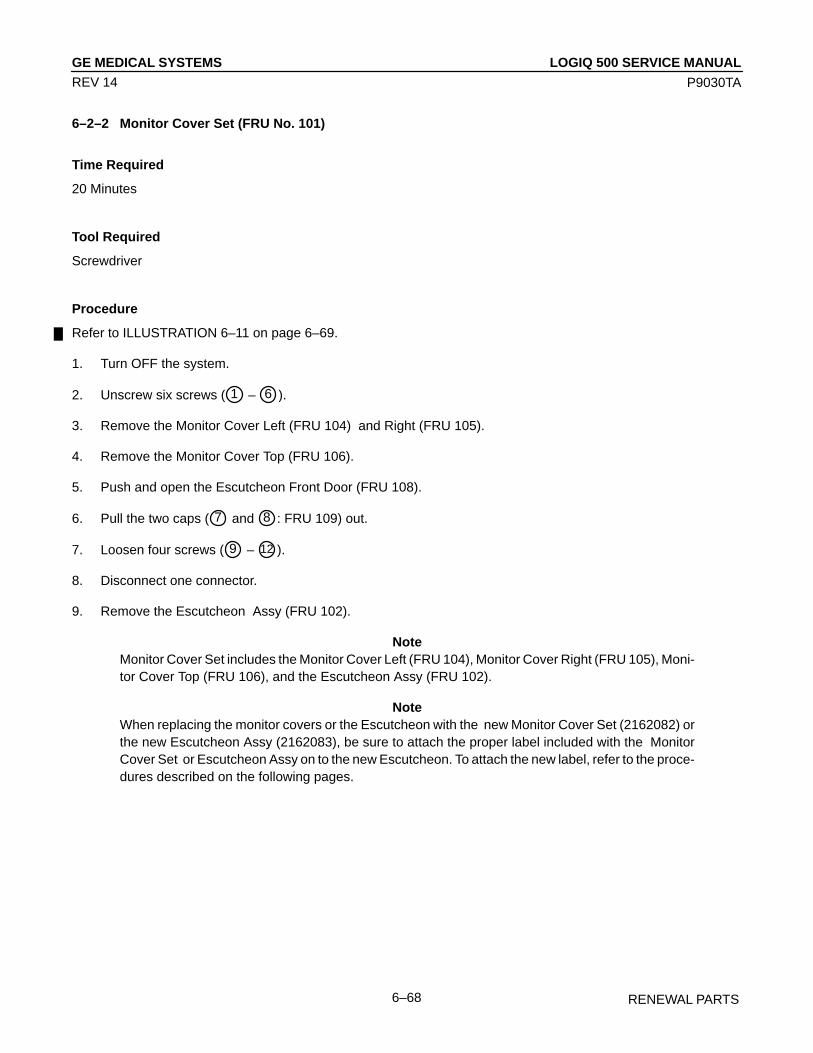
LOGIQ 500 SERVICE MANUALGE MEDICAL SYSTEMS
P9030TA
RENEWAL PARTS6–68
REV 14
6–2–2 Monitor Cover Set (FRU No. 101)
Time Required
20 Minutes
Tool Required
Screwdriver
Procedure
Refer to ILLUSTRATION 6–11 on page 6–69.
1. Turn OFF the system.
2. Unscrew six screws ( 1 – 6 ).
3. Remove the Monitor Cover Left (FRU 104) and Right (FRU 105).
4. Remove the Monitor Cover Top (FRU 106).
5. Push and open the Escutcheon Front Door (FRU 108).
6. Pull the two caps ( 7 and 8 : FRU 109) out.
7. Loosen four screws ( 9 – 12 ).
8. Disconnect one connector.
9. Remove the Escutcheon Assy (FRU 102).
NoteMonitor Cover Set includes the Monitor Cover Left (FRU 104), Monitor Cover Right (FRU 105), Moni-tor Cover Top (FRU 106), and the Escutcheon Assy (FRU 102).
NoteWhen replacing the monitor covers or the Escutcheon with the new Monitor Cover Set (2162082) orthe new Escutcheon Assy (2162083), be sure to attach the proper label included with the MonitorCover Set or Escutcheon Assy on to the new Escutcheon. To attach the new label, refer to the proce-dures described on the following pages.
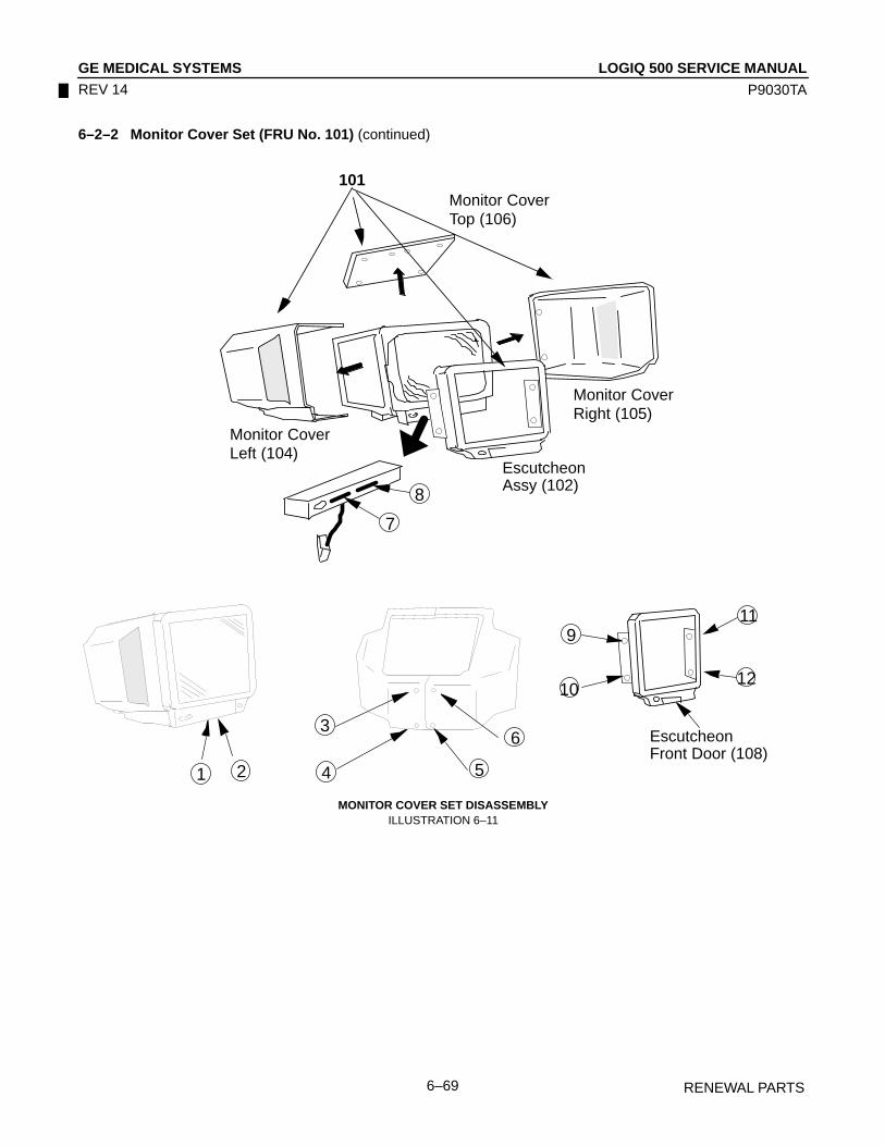
LOGIQ 500 SERVICE MANUALGE MEDICAL SYSTEMS
P9030TA
RENEWAL PARTS6–69
REV 14
6–2–2 Monitor Cover Set (FRU No. 101) (continued)
9
10
11
12
3
4 5
6
7
8
101
EscutcheonAssy (102)
Monitor CoverRight (105)
Monitor CoverLeft (104)
Monitor CoverTop (106)
1 2
EscutcheonFront Door (108)
MONITOR COVER SET DISASSEMBLYILLUSTRATION 6–11
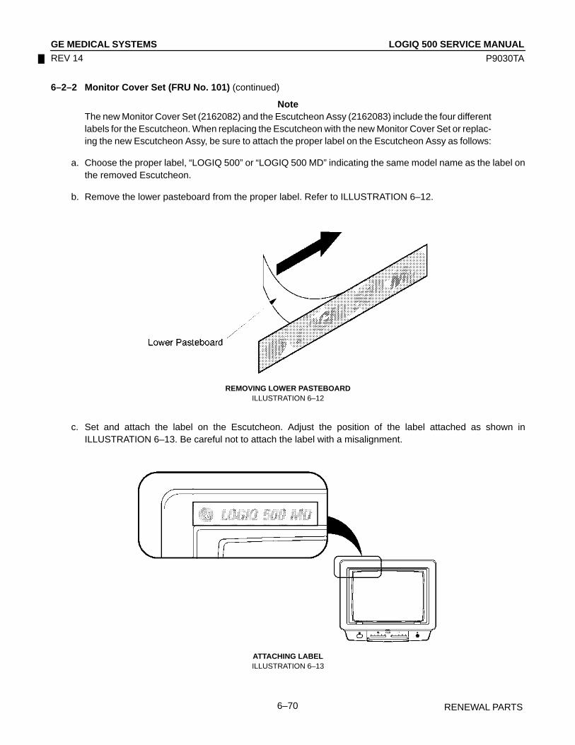
LOGIQ 500 SERVICE MANUALGE MEDICAL SYSTEMS
P9030TA
RENEWAL PARTS6–70
REV 14
6–2–2 Monitor Cover Set (FRU No. 101) (continued)
NoteThe new Monitor Cover Set (2162082) and the Escutcheon Assy (2162083) include the four differentlabels for the Escutcheon. When replacing the Escutcheon with the new Monitor Cover Set or replac-ing the new Escutcheon Assy, be sure to attach the proper label on the Escutcheon Assy as follows:
a. Choose the proper label, “LOGIQ 500” or “LOGIQ 500 MD” indicating the same model name as the label onthe removed Escutcheon.
b. Remove the lower pasteboard from the proper label. Refer to ILLUSTRATION 6–12.
REMOVING LOWER PASTEBOARDILLUSTRATION 6–12
c. Set and attach the label on the Escutcheon. Adjust the position of the label attached as shown inILLUSTRATION 6–13. Be careful not to attach the label with a misalignment.
ATTACHING LABELILLUSTRATION 6–13

LOGIQ 500 SERVICE MANUALGE MEDICAL SYSTEMS
P9030TA
RENEWAL PARTS6–71
REV 14
6–2–2 Monitor Cover Set (FRU No. 101) (continued)
d. Press down the label all around.
e. Remove the upper pasteboard from the label. refer to ILLUSTRATION 6–14.
REMOVING UPPER PASTEBOARDILLUSTRATION 6–14
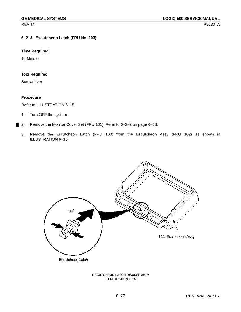
LOGIQ 500 SERVICE MANUALGE MEDICAL SYSTEMS
P9030TA
RENEWAL PARTS6–72
REV 14
6–2–3 Escutcheon Latch (FRU No. 103)
Time Required
10 Minute
Tool Required
Screwdriver
Procedure
Refer to ILLUSTRATION 6–15.
1. Turn OFF the system.
2. Remove the Monitor Cover Set (FRU 101). Refer to 6–2–2 on page 6–68.
3. Remove the Escutcheon Latch (FRU 103) from the Escutcheon Assy (FRU 102) as shown inILLUSTRATION 6–15.
ESCUTCHEON LATCH DISASSEMBLYILLUSTRATION 6–15

LOGIQ 500 SERVICE MANUALGE MEDICAL SYSTEMS
P9030TA
RENEWAL PARTS6–73
REV 14
6–2–4 Escutcheon Front Door (FRU No. 108)
Time Required
1 Minute
Tool Required
Not necessary
Procedure
Refer to ILLUSTRATION 6–16.
1. Turn OFF the system.
2. Pull out the Escutcheon Front Door (FRU 108) from the Escutcheon Assy (FRU 102) as shown inILLUSTRATION 6–16.
ESCUTCHEON FRONT DOOR DISASSEMBLYILLUSTRATION 6–16

LOGIQ 500 SERVICE MANUALGE MEDICAL SYSTEMS
P9030TA
RENEWAL PARTS6–74
REV 14
6–2–5 CRT Cap Set (FRU No. 109)
Time Required
1 Minute
Tool Required
Not necessary
Procedure
Refer to ILLUSTRATION 6–17.
1. Turn OFF the system.
2. Remove the Escutcheon Front Door (FRU 108). Refer to 6–2–4 on page 6–73.
3. Pull out two CRT Caps (FRU 109) from the front side of the Monitor Assy (FRU 100).
109CRT CAP SET DISASSEMBLY
ILLUSTRATION 6–17
NoteThe CRT Cap Set (FRU109) includes the key top for lamp switch.
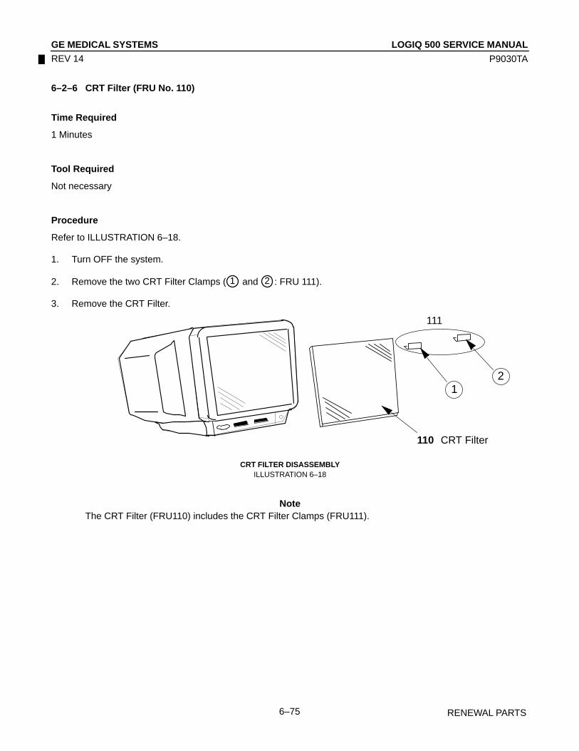
LOGIQ 500 SERVICE MANUALGE MEDICAL SYSTEMS
P9030TA
RENEWAL PARTS6–75
REV 14
6–2–6 CRT Filter (FRU No. 110)
Time Required
1 Minutes
Tool Required
Not necessary
Procedure
Refer to ILLUSTRATION 6–18.
1. Turn OFF the system.
2. Remove the two CRT Filter Clamps ( 1 and 2 : FRU 111).
3. Remove the CRT Filter.
110
1
111
2
CRT Filter
CRT FILTER DISASSEMBLYILLUSTRATION 6–18
NoteThe CRT Filter (FRU110) includes the CRT Filter Clamps (FRU111).

LOGIQ 500 SERVICE MANUALGE MEDICAL SYSTEMS
P9030TA
RENEWAL PARTS6–76
REV 14
6–2–7 Accessory Assy (FRU No. 112)
Time Required
0.5 Hours
Tool Required
Screwdriver
Procedure
Refer to ILLUSTRATION 6–19.
1. Turn OFF the system.
2. Remove the Monitor Cover Set (FRU 101). Refer to 6–2–2 on page 6–68.
3. Unscrew five screws ( 1 – 5 ).
4. Disconnect one connector ( 6 ).
5. Remove the Accessory Assy (FRU 112).
ACCESSORY ASSY DISASSEMBLYILLUSTRATION 6–19
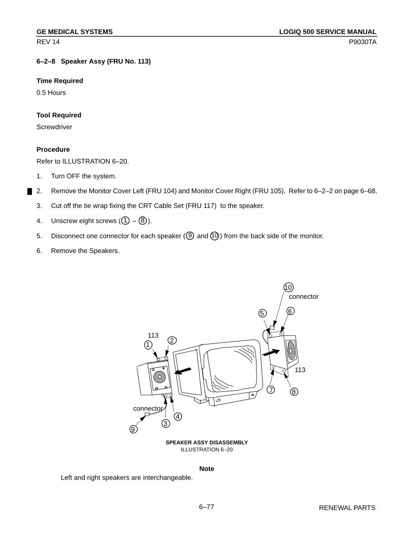
LOGIQ 500 SERVICE MANUALGE MEDICAL SYSTEMS
P9030TA
RENEWAL PARTS6–77
REV 14
6–2–8 Speaker Assy (FRU No. 113)
Time Required
0.5 Hours
Tool Required
Screwdriver
Procedure
Refer to ILLUSTRATION 6–20.
1. Turn OFF the system.
2. Remove the Monitor Cover Left (FRU 104) and Monitor Cover Right (FRU 105). Refer to 6–2–2 on page 6–68.
3. Cut off the tie wrap fixing the CRT Cable Set (FRU 117) to the speaker.
4. Unscrew eight screws ( 1 – 8 ).
5. Disconnect one connector for each speaker ( 9 and 10 ) from the back side of the monitor.
6. Remove the Speakers.
ÎÎÎÎ
113
ÎÎÎ
ÎÎÎÎ
ÎÎÎÎ
Î
113
2
34
5 6
7
9
10
1
8
connector
connector
ÎÎÎÎ
ÎÎÎÎÎ
ÎÎÎ
SPEAKER ASSY DISASSEMBLYILLUSTRATION 6–20
NoteLeft and right speakers are interchangeable.
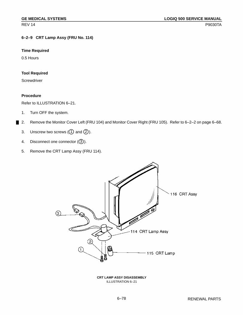
LOGIQ 500 SERVICE MANUALGE MEDICAL SYSTEMS
P9030TA
RENEWAL PARTS6–78
REV 14
6–2–9 CRT Lamp Assy (FRU No. 114)
Time Required
0.5 Hours
Tool Required
Screwdriver
Procedure
Refer to ILLUSTRATION 6–21.
1. Turn OFF the system.
2. Remove the Monitor Cover Left (FRU 104) and Monitor Cover Right (FRU 105). Refer to 6–2–2 on page 6–68.
3. Unscrew two screws ( 1 and 2 ).
4. Disconnect one connector ( 3 ).
5. Remove the CRT Lamp Assy (FRU 114).
CRT LAMP ASSY DISASSEMBLYILLUSTRATION 6–21

LOGIQ 500 SERVICE MANUALGE MEDICAL SYSTEMS
P9030TA
RENEWAL PARTS6–79
REV 14
This page is left blank intentionally.

LOGIQ 500 SERVICE MANUALGE MEDICAL SYSTEMS
P9030TA
RENEWAL PARTS6–80
REV 14
6–2–10 CRT Assy (FRU No. 116)
Time Required
0.5 Hours
Tool Required
ScrewdriverHexagonal Wrench
Procedure
WARNING!
PERSONAL INJURY HAZARD. VIDEO MONITOR SUPPORT ARM IS SPRING LOADED. RE-LEASING ARM WHEN MONITOR IS NOT INSTALLED WILL CAUSE SUDDEN UPWARD MOVE-MENT. KEEP YOUR HEAD AND BODY AWAY FROM ABOVE VIDEO MONITOR SUPPORT ARM.
Refer to ILLUSTRATION 6–22 on page 6–81.
1. Turn OFF the system.
2. Remove the Monitor Assy (FRU 100). Refer to 6–2–1 on page 6–66.
3. Remove the Monitor Cover Set ( 1 : FRU 101) Refer to 6–2–2 on page 6–68.
4. Remove the Speaker Assy ( 2 : FRU 113) Refer to 6–2–8 on page 6–77.
5. Remove the tilt mechanism.
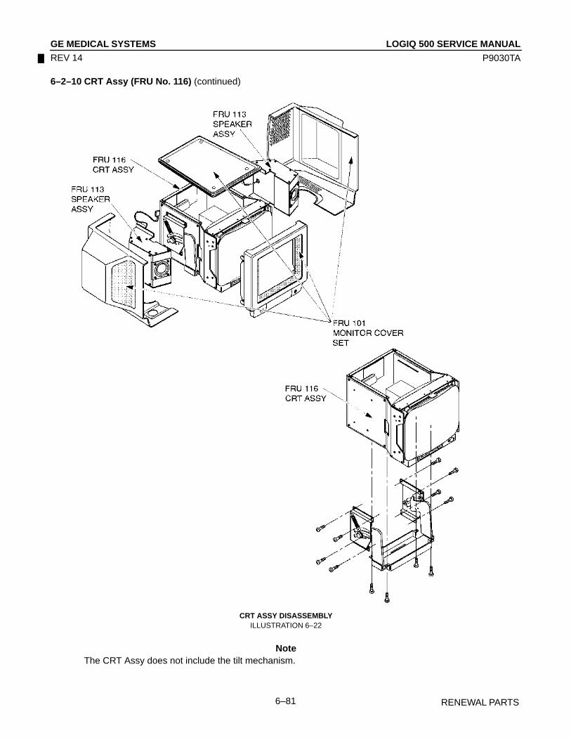
LOGIQ 500 SERVICE MANUALGE MEDICAL SYSTEMS
P9030TA
RENEWAL PARTS6–81
REV 14
6–2–10 CRT Assy (FRU No. 116) (continued)
CRT ASSY DISASSEMBLYILLUSTRATION 6–22
NoteThe CRT Assy does not include the tilt mechanism.

LOGIQ 500 SERVICE MANUALGE MEDICAL SYSTEMS
P9030TA
RENEWAL PARTS6–82
REV 14
6–2–11 CRT Cable Set (FRU No. 117)
Time Required
0.5 Hour
Tool Required
ScrewdriverHexagonal Wrench
Procedure
Refer to ILLUSTRATION 6–23.
1. Turn OFF the system.
2. Remove the Monitor Assy (FRU 100). Refer to 6–2–1 on page 6–66.
3. Remove the Monitor Cover Set (FRU 101). Refer to 6–2–2 on page 6–68.
4. Disconnect three connectors ( 1 – 3 ) from the back side of the CRT Assy.
CRT ASSY DISASSEMBLYILLUSTRATION 6–23

LOGIQ 500 SERVICE MANUALGE MEDICAL SYSTEMS
P9030TA
RENEWAL PARTS6–83
REV 14
This page is left blank intentionally.

LOGIQ 500 SERVICE MANUALGE MEDICAL SYSTEMS
P9030TA
RENEWAL PARTS6–84
REV 14
6–2–12 Monitor15 Assy (FRU No. 170)
Time Required
0.25 Hours
Tool Required
ScrewdriverHexagonal Wrench
Procedure
WARNING!
PERSONAL INJURY HAZARD. VIDEO MONITOR SUPPORT ARM IS SPRING LOADED. RE-LEASING ARM WHEN MONITOR IS NOT INSTALLED WILL CAUSE SUDDEN UPWARD MOVE-MENT. KEEP YOUR HEAD AND BODY AWAY FROM ABOVE VIDEO MONITOR SUPPORT ARM.
Refer to ILLUSTRATION 6–24 on page 6–85.
1. Turn OFF the system.
2. Unscrew four hexagonal screws ( 1 – 4 ) located beneath the horizontal part of the Neck Assy.
3. Remove the cover located at the bottom of the Neck Assy.
4. Unscrew two screws ( 5 and 6 ) and remove the plate fixing the cables.
5. Disconnect the four connectors ( 7 – 10 ).
6. Remove the screw cap located at position ( 11 ).
7. Loosen one screw ( 11 ) and pull the Monitor15 Assy upwards.
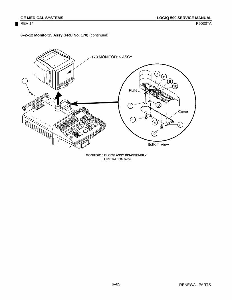
LOGIQ 500 SERVICE MANUALGE MEDICAL SYSTEMS
P9030TA
RENEWAL PARTS6–85
REV 14
6–2–12 Monitor15 Assy (FRU No. 170) (continued)
MONITOR15 BLOCK ASSY DISASSEMBLYILLUSTRATION 6–24

LOGIQ 500 SERVICE MANUALGE MEDICAL SYSTEMS
P9030TA
RENEWAL PARTS6–86
REV 14
6–2–13 Monitor15 Cover Set (FRU No. 171)
Time Required
20 Minutes
Tool Required
Screwdriver
Procedure
Refer to ILLUSTRATION 6–25 on page 6–87.
1. Turn OFF the system.
2. Unscrew two screws ( 1 – 2 ).
3. Remove the LAMP SHADE2 (FRU179).
4. Unscrew six screws ( 3 – 8 ).
5. Remove the Monitor Cover L2 Assy (FRU 173) and R2 Assy (FRU 174).
6. Remove the Tray2 Assy (FRU 175).
7. Loosen four screws ( 9 – 12 ).
8. Remove the Escutcheon2 Assy (FRU 172).
9. Disconnect one connector ( 13 ).
10. Disconnect one connector ( 14 ) from the back side of the Escutcheon2 Assy.
NoteMonitor15 Cover Set includes the Monitor Cover L2 Assy (FRU 173), Monitor Cover R2 Assy (FRU 174), Tray2 Assy (FRU 175), and the Escutcheon2 Assy (FRU 172).

LOGIQ 500 SERVICE MANUALGE MEDICAL SYSTEMS
P9030TA
RENEWAL PARTS6–87
REV 14
6–2–13 Monitor15 Cover Set (FRU No. 171) (continued)
MONITOR COVER SET DISASSEMBLYILLUSTRATION 6–25

LOGIQ 500 SERVICE MANUALGE MEDICAL SYSTEMS
P9030TA
RENEWAL PARTS6–88
REV 14
This page is left blank intentionally.
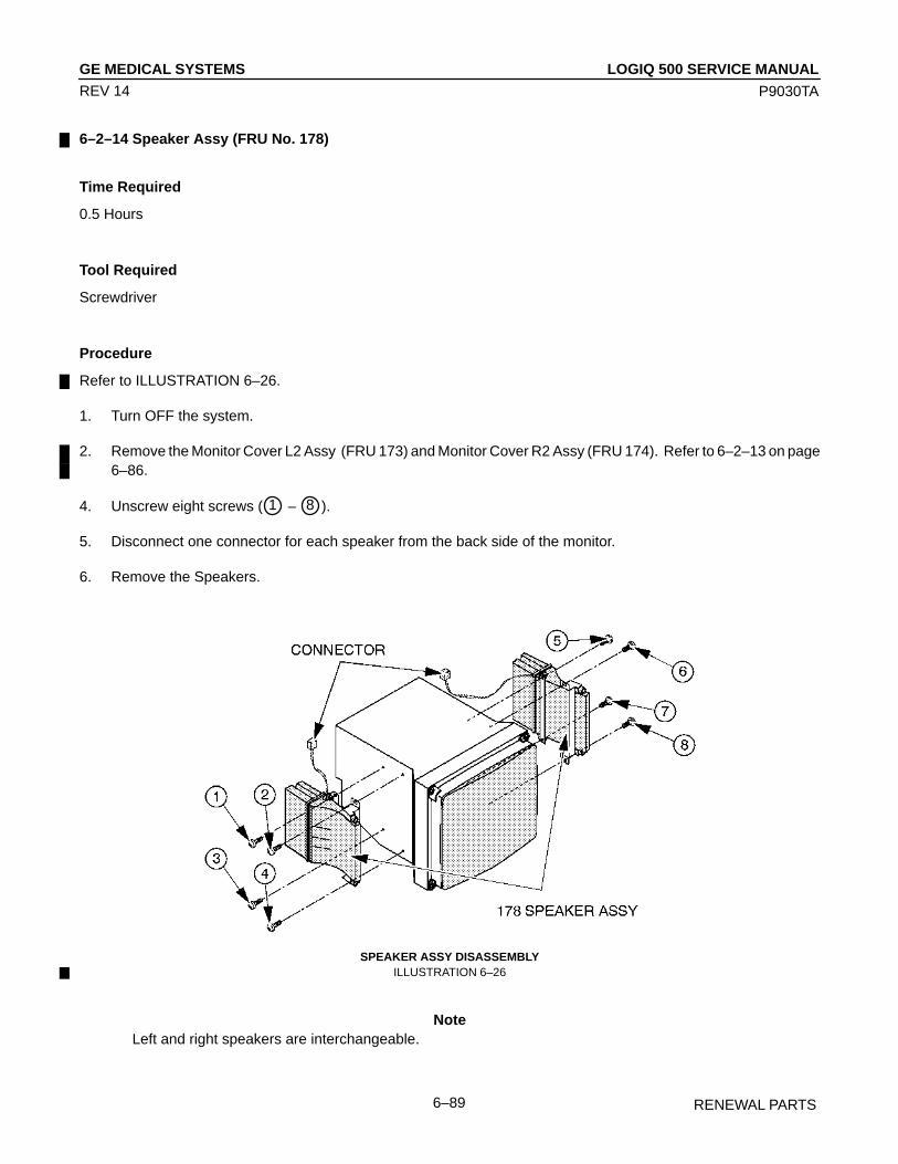
LOGIQ 500 SERVICE MANUALGE MEDICAL SYSTEMS
P9030TA
RENEWAL PARTS6–89
REV 14
6–2–14 Speaker Assy (FRU No. 178)
Time Required
0.5 Hours
Tool Required
Screwdriver
Procedure
Refer to ILLUSTRATION 6–26.
1. Turn OFF the system.
2. Remove the Monitor Cover L2 Assy (FRU 173) and Monitor Cover R2 Assy (FRU 174). Refer to 6–2–13 on page6–86.
4. Unscrew eight screws ( 1 – 8 ).
5. Disconnect one connector for each speaker from the back side of the monitor.
6. Remove the Speakers.
SPEAKER ASSY DISASSEMBLYILLUSTRATION 6–26
NoteLeft and right speakers are interchangeable.
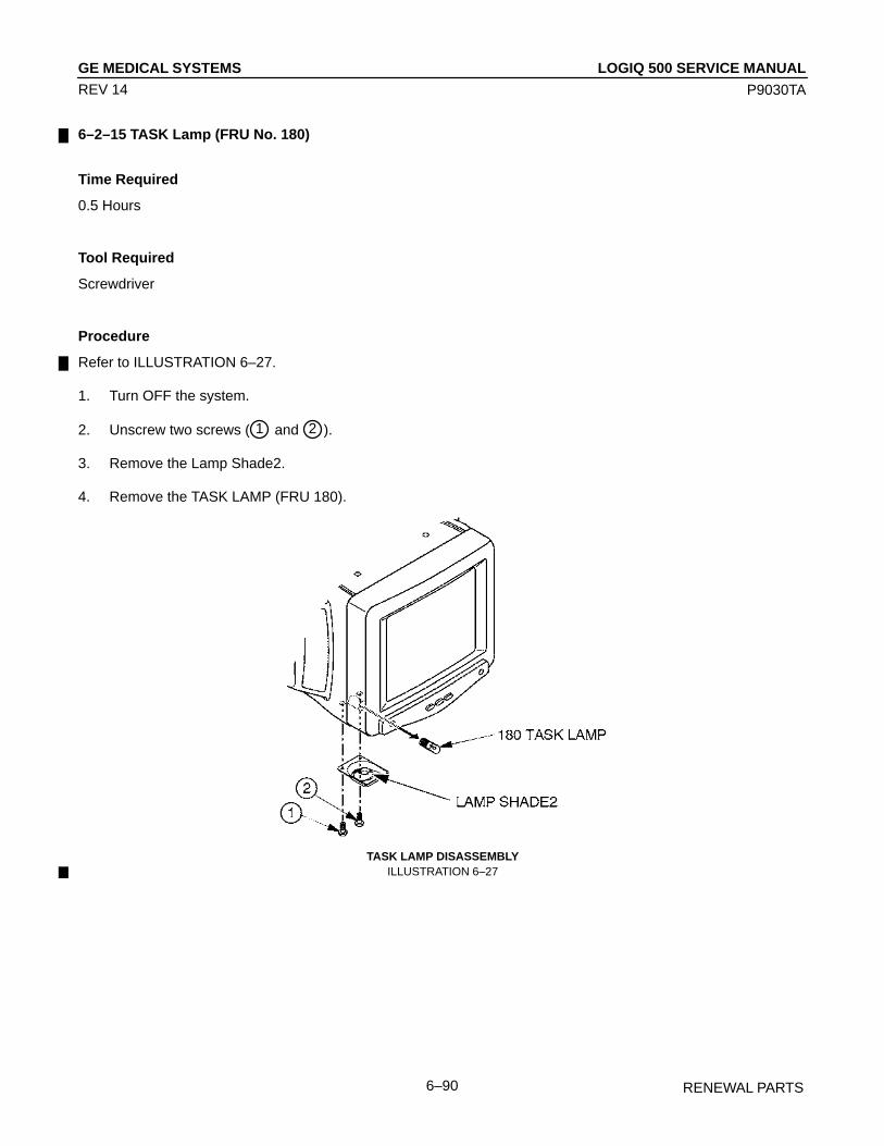
LOGIQ 500 SERVICE MANUALGE MEDICAL SYSTEMS
P9030TA
RENEWAL PARTS6–90
REV 14
6–2–15 TASK Lamp (FRU No. 180)
Time Required
0.5 Hours
Tool Required
Screwdriver
Procedure
Refer to ILLUSTRATION 6–27.
1. Turn OFF the system.
2. Unscrew two screws ( 1 and 2 ).
3. Remove the Lamp Shade2.
4. Remove the TASK LAMP (FRU 180).
TASK LAMP DISASSEMBLYILLUSTRATION 6–27

LOGIQ 500 SERVICE MANUALGE MEDICAL SYSTEMS
P9030TA
RENEWAL PARTS6–91
REV 14
6–2–16 CRT Cable Set (FRU No. 182)
Time Required
0.5 Hour
Tool Required
ScrewdriverHexagonal Wrench
Procedure
Refer to ILLUSTRATION 6–28.
1. Turn OFF the system.
2. Remove the Monitor15 Assy (FRU 170). Refer to 6–2–12 on page 6–84.
3. Remove the Monitor15 Cover Set (FRU 171). Refer to 6–2–13 on page 6–86.
4. Disconnect three connectors ( 1 – 3 ) from the back side of the CRT Assy.
CRT ASSY DISASSEMBLYILLUSTRATION 6–28
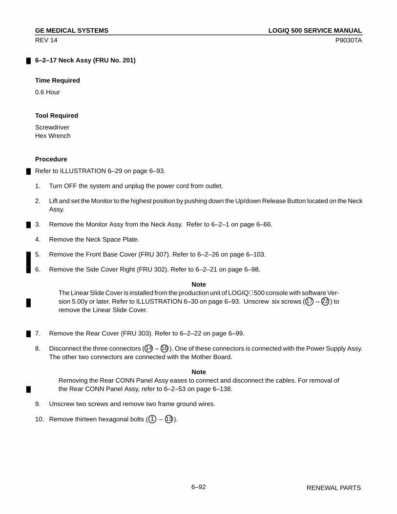
LOGIQ 500 SERVICE MANUALGE MEDICAL SYSTEMS
P9030TA
RENEWAL PARTS6–92
REV 14
6–2–17 Neck Assy (FRU No. 201)
Time Required
0.6 Hour
Tool Required
ScrewdriverHex Wrench
Procedure
Refer to ILLUSTRATION 6–29 on page 6–93.
1. Turn OFF the system and unplug the power cord from outlet.
2. Lift and set the Monitor to the highest position by pushing down the Up/down Release Button located on the NeckAssy.
3. Remove the Monitor Assy from the Neck Assy. Refer to 6–2–1 on page 6–66.
4. Remove the Neck Space Plate.
5. Remove the Front Base Cover (FRU 307). Refer to 6–2–26 on page 6–103.
6. Remove the Side Cover Right (FRU 302). Refer to 6–2–21 on page 6–98.
NoteThe Linear Slide Cover is installed from the production unit of LOGIQ 500 console with software Ver-sion 5.00y or later. Refer to ILLUSTRATION 6–30 on page 6–93. Unscrew six screws ( 17 – 22 ) toremove the Linear Slide Cover.
7. Remove the Rear Cover (FRU 303). Refer to 6–2–22 on page 6–99.
8. Disconnect the three connectors ( 14 – 16 ). One of these connectors is connected with the Power Supply Assy.The other two connectors are connected with the Mother Board.
NoteRemoving the Rear CONN Panel Assy eases to connect and disconnect the cables. For removal ofthe Rear CONN Panel Assy, refer to 6–2–53 on page 6–138.
9. Unscrew two screws and remove two frame ground wires.
10. Remove thirteen hexagonal bolts ( 1 – 13 ).

LOGIQ 500 SERVICE MANUALGE MEDICAL SYSTEMS
P9030TA
RENEWAL PARTS6–93
REV 14
6–2–17 Neck Assy (FRU No. 201) (continued)
6
14
15
16
11
1
2
3
4
5
7
8
9
10
13
12
0.
FG
FG: Frame GroundNECK ASSY DISASSEMBLY
ILLUSTRATION 6–29
LINEAR SLIDE COVER DISASSEMBLYILLUSTRATION 6–30

LOGIQ 500 SERVICE MANUALGE MEDICAL SYSTEMS
P9030TA
RENEWAL PARTS6–94
REV 14
6–2–18 Neck Grip (FRU No. 202)
Time Required
5 Minutes
Tool Required
Hexagonal Wrench
Procedure
Refer to ILLUSTRATION 6–31.
1. Turn OFF the system.
2. Unscrew two hexagonal screws ( 1 and 2 ).
3. Remove the Neck Grip (FRU 202).
NECK GRIP DISASSEMBLYILLUSTRATION 6–31
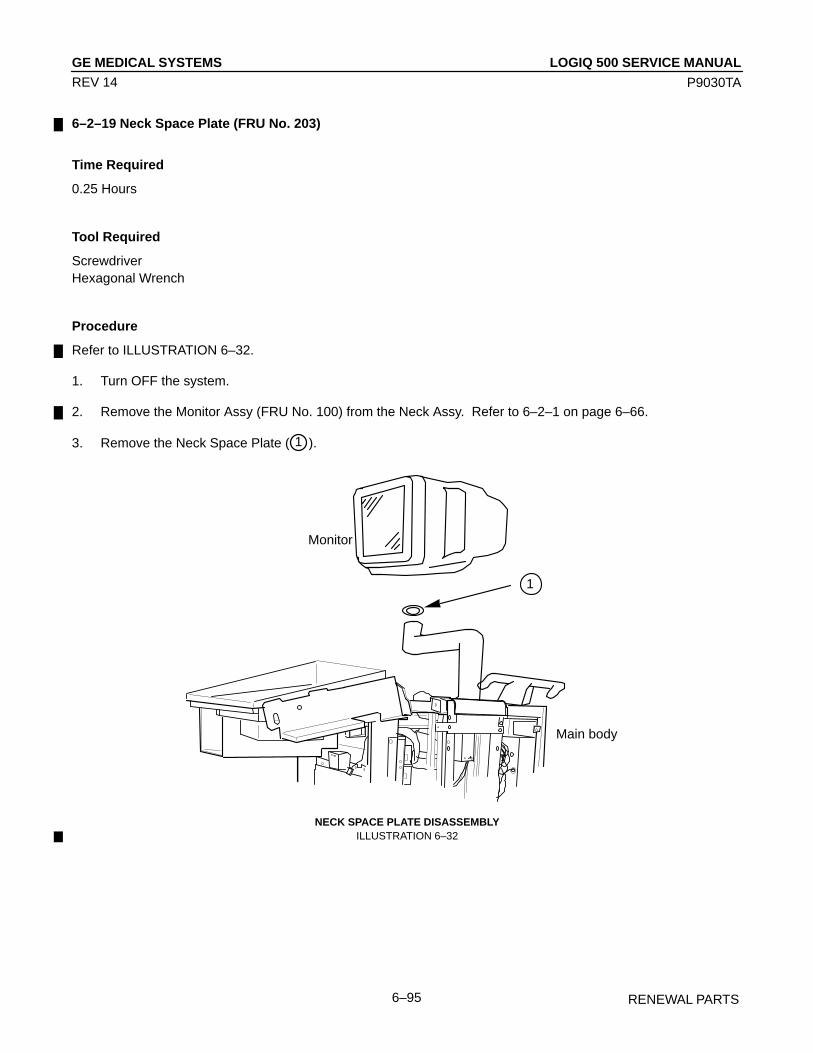
LOGIQ 500 SERVICE MANUALGE MEDICAL SYSTEMS
P9030TA
RENEWAL PARTS6–95
REV 14
6–2–19 Neck Space Plate (FRU No. 203)
Time Required
0.25 Hours
Tool Required
ScrewdriverHexagonal Wrench
Procedure
Refer to ILLUSTRATION 6–32.
1. Turn OFF the system.
2. Remove the Monitor Assy (FRU No. 100) from the Neck Assy. Refer to 6–2–1 on page 6–66.
3. Remove the Neck Space Plate ( 1 ).
1
Monitor
Main body
NECK SPACE PLATE DISASSEMBLYILLUSTRATION 6–32

LOGIQ 500 SERVICE MANUALGE MEDICAL SYSTEMS
P9030TA
RENEWAL PARTS6–96
REV 14
This page is left blank intentionally.

LOGIQ 500 SERVICE MANUALGE MEDICAL SYSTEMS
P9030TA
RENEWAL PARTS6–97
REV 14
6–2–20 Side Cover Left (FRU No. 301)
Time Required
5 Minutes
Tool Required
Screwdriver
Procedure
Refer to ILLUSTRATION 6–33.
1. Turn OFF the system.
2. Remove four screw caps and unscrew four screws ( 1 – 4 ).
3. Remove the Side Cover Left (FRU 301).
Î
ÎÎÎ
ÎÎÎÎÎÎÎÎÎÎ
ÎÎÎÎÎÎ
ÎÎÎÎÎÎÎÎÎÎÎÎÎÎÎÎÎÎÎÎÎÎÎÎÎÎÎÎ
ÎÎÎÎÎÎÎÎÎÎÎÎ
ÎÎÎÎÎÎ
ÎÎÎÎÎÎÎÎÎÎ
ÎÎÎÎÎÎÎÎÎÎÎÎÎÎÎ
ÎÎÎÎÎÎÎÎ
ÎÎÎÎÎÎÎÎÎÎÎÎÎ
ÎÎÎ
ÎÎÎÎÎÎÎÎÎÎÎÎ
ÎÎÎ
ÎÎÎÎÎÎÎÎÎÎÎÎÎÎÎÎÎÎÎÎÎÎÎÎÎÎÎÎÎÎÎÎÎÎÎÎÎÎÎÎÎÎÎÎÎÎÎÎÎÎÎÎÎÎÎ
ÎÎ
Î
Î
Î
ÎÎ
ÎÎÎÎÎÎ
Î
ÎÎÎÎÎÎÎÎÎÎÎÎÎÎÎÎÎÎÎÎÎÎÎÎÎÎÎÎÎÎÎ
ÎÎÎÎÎÎÎÎÎÎÎÎÎÎÎÎÎÎÎÎÎÎÎÎ
ÎÎ301
12
3
4
ÎÎÎÎÎÎÎÎÎÎÎÎÎÎÎÎÎÎÎÎÎÎÎÎÎÎÎÎÎÎÎÎÎÎÎÎÎÎÎÎÎÎÎÎÎÎÎÎÎÎÎÎÎÎÎ
Î
ÎÎÎÎÎ
ÎÎ
ÎÎÎÎÎÎÎÎÎÎ
ÎÎÎÎÎÎÎÎÎÎÎÎÎÎÎÎÎÎÎÎÎ
ÎÎÎÎÎÎÎÎÎÎÎÎÎÎÎÎÎÎÎÎÎÎÎÎÎÎÎÎ
ÎÎÎÎÎÎÎ
ÎÎÎÎÎÎÎÎÎÎÎÎÎ
SIDE COVER LEFT DISASSEMBLYILLUSTRATION 6–33

LOGIQ 500 SERVICE MANUALGE MEDICAL SYSTEMS
P9030TA
RENEWAL PARTS6–98
REV 14
6–2–21 Side Cover Right (FRU No. 302)
Time Required
5 Minutes
Tool Required
Screwdriver
Procedure
Refer to ILLUSTRATION 6–34.
1. Turn OFF the system.
2. Unscrew four screws and remove the Front Base Cover (FRU No. 307). Refer to 6–2–26 on page 6–103.
3. Remove the five screw caps and unscrew five screws ( 1 – 5 ).
4. Open the Rear Door and remove the Side Cover Right.
302
1
2
3
4
307 Front Base Cover
5
RIGHT COVER DISASSEMBLYILLUSTRATION 6–34
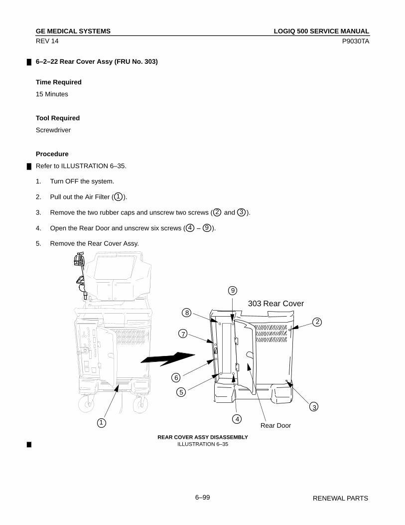
LOGIQ 500 SERVICE MANUALGE MEDICAL SYSTEMS
P9030TA
RENEWAL PARTS6–99
REV 14
6–2–22 Rear Cover Assy (FRU No. 303)
Time Required
15 Minutes
Tool Required
Screwdriver
Procedure
Refer to ILLUSTRATION 6–35.
1. Turn OFF the system.
2. Pull out the Air Filter ( 1 ).
3. Remove the two rubber caps and unscrew two screws ( 2 and 3 ).
4. Open the Rear Door and unscrew six screws ( 4 – 9 ).
5. Remove the Rear Cover Assy.
303
1
3
9
8
5
4Rear Door
7
6
Rear Cover
2
REAR COVER ASSY DISASSEMBLYILLUSTRATION 6–35
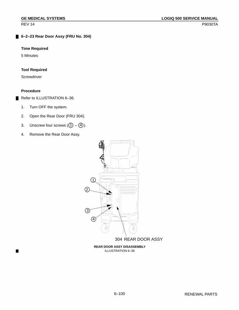
LOGIQ 500 SERVICE MANUALGE MEDICAL SYSTEMS
P9030TA
RENEWAL PARTS6–100
REV 14
6–2–23 Rear Door Assy (FRU No. 304)
Time Required
5 Minutes
Tool Required
Screwdriver
Procedure
Refer to ILLUSTRATION 6–36.
1. Turn OFF the system.
2. Open the Rear Door (FRU 304).
3. Unscrew four screws ( 1 – 4 ).
4. Remove the Rear Door Assy.
ÎÎÎÎ
ÎÎÎÎ ÎÎ
ÎÎÎÎÎÎ
ÎÎÎ ÎÎÎÎÎÎÎÎÎ
ÎÎÎÎÎÎÎÎÎÎÎÎÎÎÎÎ
Î ÎÎ
ÎÎÎÎÎÎ
ÎÎÎÎÎ
ÎÎÎÎÎÎ
ÎÎÎÎ
Î ÎÎ
Î
Î
ÎÎÎÎ
ÎÎÎÎ
Î
ÎÎÎÎÎÎÎÎÎÎÎÎÎÎÎÎÎÎÎÎÎ
ÎÎÎÎ
ÎÎÎÎÎ
ÎÎÎÎÎÎÎÎÎÎÎÎÎÎÎÎÎÎÎÎÎÎÎÎÎÎÎÎÎÎÎÎÎÎÎÎÎÎÎÎÎÎÎÎÎÎÎÎÎÎÎÎÎÎÎÎÎÎÎÎÎÎÎÎÎÎÎÎÎÎÎÎ
ÎÎ
ÎÎÎÎÎÎÎÎÎÎÎÎÎÎÎÎÎÎÎÎÎÎÎÎÎÎ
ÎÎÎÎÎÎÎÎÎÎÎÎÎÎÎÎÎÎÎÎÎ
ÎÎÎÎ
ÎÎÎÎÎÎÎÎÎÎÎÎÎÎÎÎÎÎÎÎÎÎÎÎÎÎÎÎ
ÎÎ
ÎÎÎ
ÎÎÎÎÎÎÎÎÎÎÎÎÎÎÎÎÎÎÎÎÎÎÎÎÎÎÎÎÎÎÎÎÎÎÎÎÎÎÎÎÎÎ
ÎÎÎÎÎÎ
1
2
3
4
304 REAR DOOR ASSY
REAR DOOR ASSY DISASSEMBLYILLUSTRATION 6–36
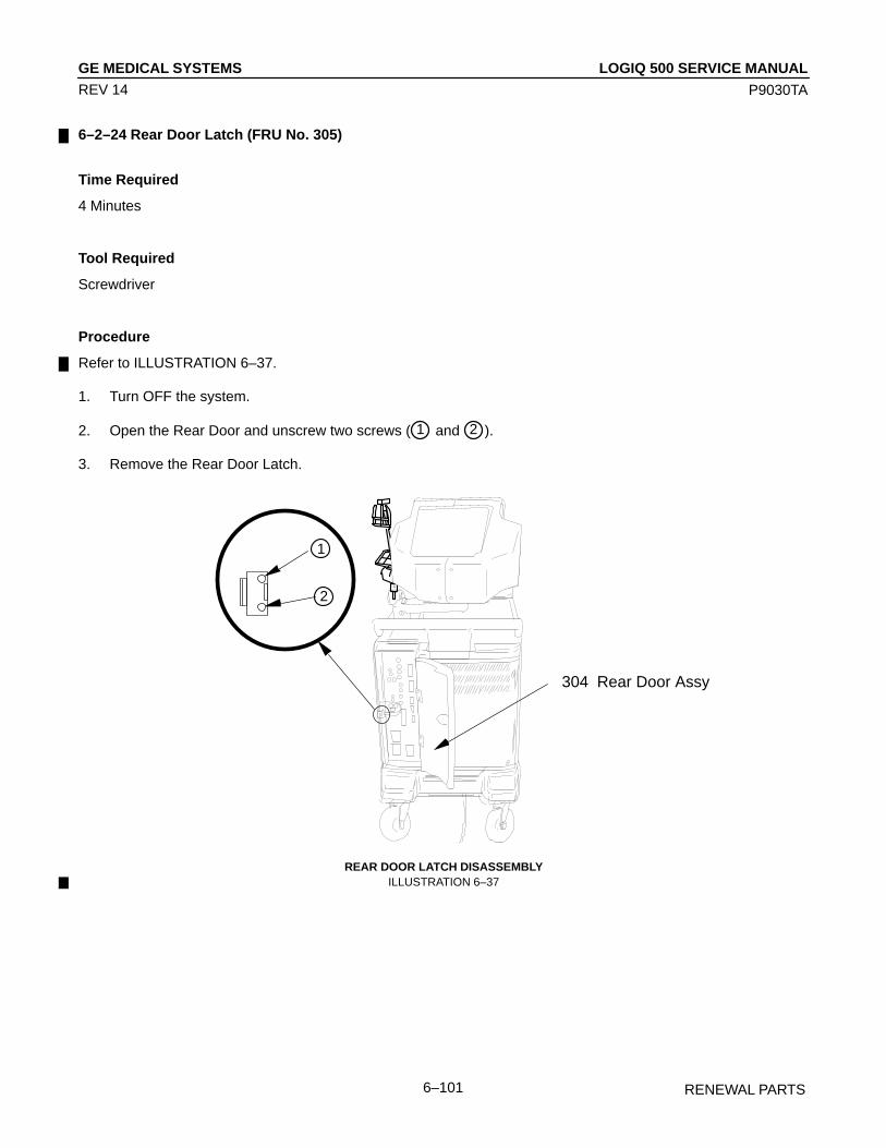
LOGIQ 500 SERVICE MANUALGE MEDICAL SYSTEMS
P9030TA
RENEWAL PARTS6–101
REV 14
6–2–24 Rear Door Latch (FRU No. 305)
Time Required
4 Minutes
Tool Required
Screwdriver
Procedure
Refer to ILLUSTRATION 6–37.
1. Turn OFF the system.
2. Open the Rear Door and unscrew two screws ( 1 and 2 ).
3. Remove the Rear Door Latch.
1
2
304 Rear Door Assy
REAR DOOR LATCH DISASSEMBLYILLUSTRATION 6–37
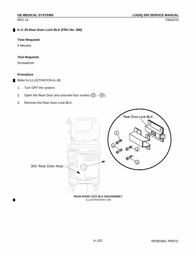
LOGIQ 500 SERVICE MANUALGE MEDICAL SYSTEMS
P9030TA
RENEWAL PARTS6–102
REV 14
6–2–25 Rear Door Lock BLK (FRU No. 306)
Time Required
4 Minutes
Tool Required
Screwdriver
Procedure
Refer to ILLUSTRATION 6–38.
1. Turn OFF the system.
2. Open the Rear Door and unscrew four screws ( 1 – 4 ).
3. Remove the Rear Door Lock BLK.
304 Rear Door Assy
REAR DOOR LOCK BLK DISASSEMBLYILLUSTRATION 6–38
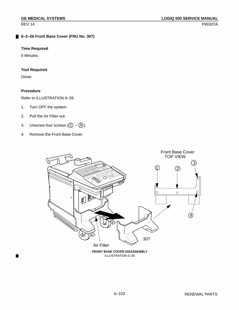
LOGIQ 500 SERVICE MANUALGE MEDICAL SYSTEMS
P9030TA
RENEWAL PARTS6–103
REV 14
6–2–26 Front Base Cover (FRU No. 307)
Time Required
5 Minutes
Tool Required
Driver
Procedure
Refer to ILLUSTRATION 6–39.
1. Turn OFF the system.
2. Pull the Air Filter out.
3. Unscrew four screws ( 1 – 4 ).
4. Remove the Front Base Cover.
Î
ÎÎ
ÎÎÎÎÎ
ÎÎÎÎÎÎ
ÎÎÎÎÎÎÎÎÎÎÎÎÎÎÎÎÎÎÎÎÎÎÎÎÎÎÎÎ
ÎÎÎÎÎÎÎÎÎÎÎÎ
ÎÎÎÎÎÎÎÎÎÎ
ÎÎÎÎÎÎ
ÎÎÎÎ
ÎÎÎÎÎÎÎÎÎÎÎÎ
ÎÎÎÎÎÎÎÎÎÎ
ÎÎÎÎÎÎÎÎÎÎÎÎÎÎÎÎ
ÎÎ
ÎÎÎÎÎÎÎÎÎÎÎÎ
ÎÎÎÎÎÎÎÎÎÎÎÎÎÎÎÎÎÎÎÎÎÎÎÎÎÎÎÎÎÎÎÎÎÎÎÎÎÎÎÎÎÎÎÎÎÎÎÎÎÎÎÎÎÎÎÎÎÎÎÎÎÎÎÎ
Î
ÎÎÎÎÎÎ
ÎÎÎÎÎÎÎÎÎÎÎÎÎÎÎ
ÎÎÎÎÎÎÎÎÎÎÎÎÎÎÎÎÎÎÎÎÎÎ
ÎÎÎÎÎÎÎÎÎÎÎ
ÎÎÎÎÎÎÎÎÎÎ
ÎÎÎÎÎÎÎÎÎÎÎÎÎ
307
ÎÎÎÎ
ÎÎÎÎ
ÎÎ
ÎÎ
ÎÎÎÎÎÎÎÎÎ
ÎÎÎÎÎÎÎÎÎ
1 23
4
Front Base CoverTOP VIEW
ÎÎÎÎÎÎÎÎÎÎÎÎÎÎÎÎÎÎÎÎÎÎÎÎÎÎÎÎÎÎÎÎÎÎÎÎÎÎÎÎÎÎÎÎÎÎÎÎÎÎÎÎÎÎÎ
ÎÎ
ÎÎ
Î
Î
ÎÎÎÎÎÎÎÎ
Î
ÎÎÎÎÎÎÎÎÎÎÎÎÎÎÎÎÎÎÎÎÎÎÎÎÎÎ
ÎÎÎÎÎÎÎÎÎÎÎÎÎÎÎÎÎÎÎÎÎÎÎÎÎÎÎÎ
Air FilterFRONT BASE COVER DISASSEMBLY
ILLUSTRATION 6–39
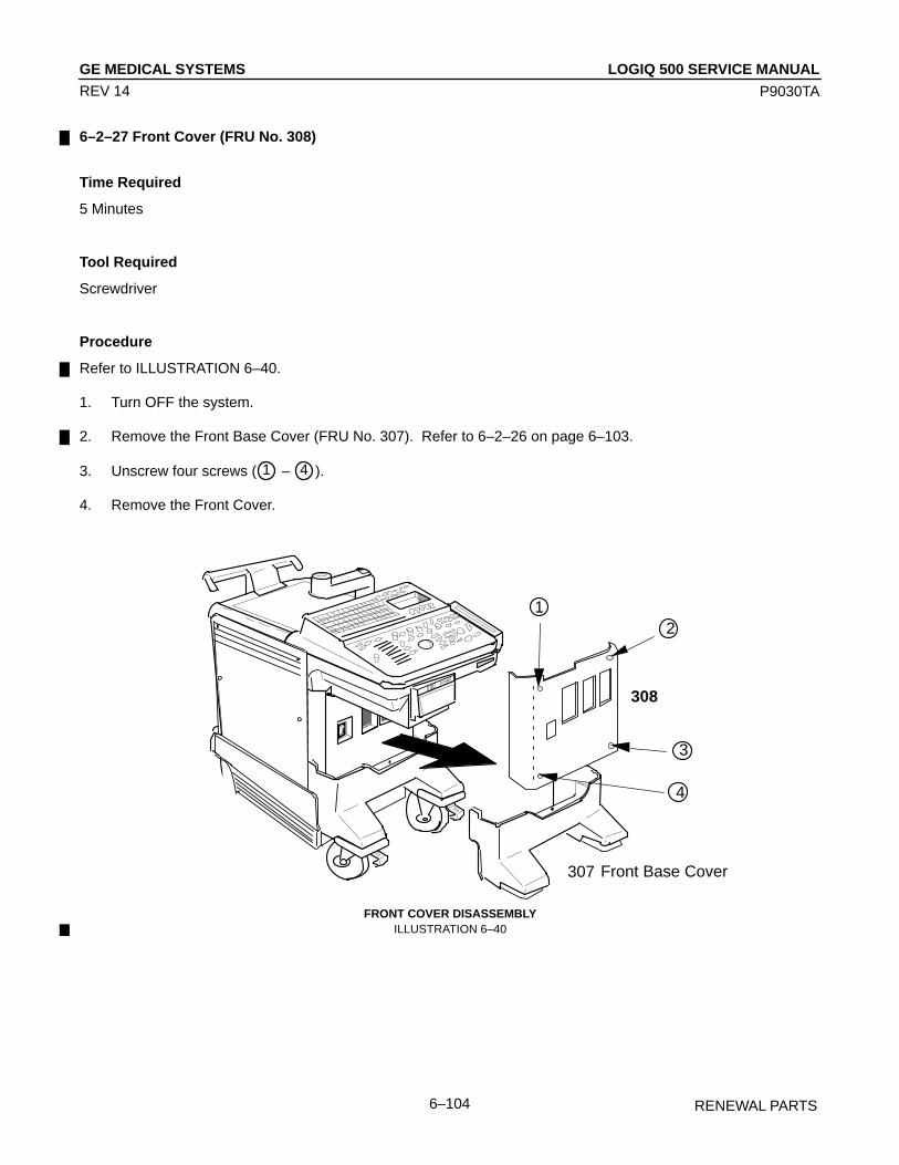
LOGIQ 500 SERVICE MANUALGE MEDICAL SYSTEMS
P9030TA
RENEWAL PARTS6–104
REV 14
6–2–27 Front Cover (FRU No. 308)
Time Required
5 Minutes
Tool Required
Screwdriver
Procedure
Refer to ILLUSTRATION 6–40.
1. Turn OFF the system.
2. Remove the Front Base Cover (FRU No. 307). Refer to 6–2–26 on page 6–103.
3. Unscrew four screws ( 1 – 4 ).
4. Remove the Front Cover.
Î
ÎÎ
ÎÎ
ÎÎÎÎ
ÎÎÎÎÎÎ
ÎÎÎÎÎÎÎÎÎÎÎÎÎÎÎÎÎÎÎÎÎÎÎÎÎÎÎÎÎÎÎÎÎÎÎ
ÎÎÎÎÎÎÎÎÎÎÎ
ÎÎÎÎÎ
ÎÎÎÎÎÎÎÎ
ÎÎÎÎÎÎÎÎÎÎÎÎÎÎÎ
ÎÎÎÎÎÎÎÎÎÎ
ÎÎÎÎÎÎÎÎ
ÎÎÎÎÎÎÎÎÎ
ÎÎÎ
ÎÎÎÎÎÎÎÎÎÎÎÎ
ÎÎÎÎÎÎÎÎÎÎÎÎÎÎÎÎÎÎÎÎÎÎÎÎÎÎÎÎÎÎÎÎÎÎÎÎÎÎÎÎÎÎÎÎÎÎÎÎÎÎÎÎÎÎÎÎÎÎÎÎÎÎÎÎ
ÎÎ
ÎÎÎÎÎÎ
Î
ÎÎÎÎÎÎÎÎÎÎÎÎÎÎÎÎ
ÎÎÎÎÎÎÎÎÎÎ
ÎÎÎÎÎÎÎÎÎÎÎ
ÎÎÎÎÎÎÎÎÎÎÎÎÎÎÎÎÎ
ÎÎÎÎÎÎÎÎÎÎ
ÎÎÎÎÎÎÎÎÎÎÎÎÎÎÎ
307
ÎÎÎÎÎÎÎÎÎÎÎÎÎÎÎÎÎÎÎÎÎÎÎÎÎÎÎÎÎÎÎÎÎÎÎÎÎÎÎÎÎÎ
ÎÎ
Î
ÎÎÎÎ
Î
12
3
4
308
Front Base Cover
ÎÎÎÎÎÎÎÎÎÎÎÎÎÎÎÎÎÎÎÎÎÎÎÎÎÎÎÎÎÎÎÎÎÎÎÎÎÎÎÎÎÎÎÎÎÎÎÎÎÎÎÎÎÎÎÎÎÎÎÎÎÎÎÎÎÎ
Î
ÎÎ
Î
Î
Î
ÎÎÎÎÎÎÎÎ
ÎÎ
ÎÎÎÎÎÎÎÎÎÎÎÎÎÎÎÎÎÎÎÎÎÎÎÎÎÎÎÎÎÎÎ
ÎÎÎÎÎÎÎÎÎÎÎÎÎÎÎÎÎÎÎÎÎÎÎÎÎÎÎÎÎÎÎÎÎÎÎ
FRONT COVER DISASSEMBLYILLUSTRATION 6–40
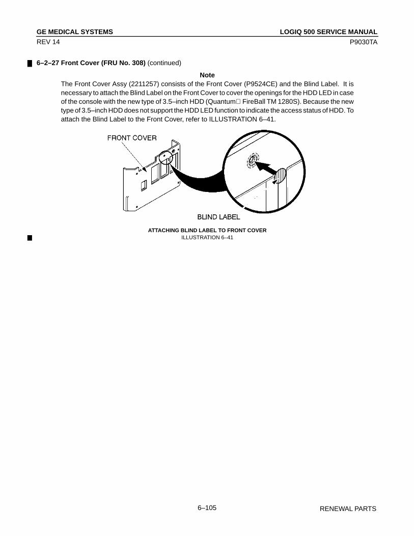
LOGIQ 500 SERVICE MANUALGE MEDICAL SYSTEMS
P9030TA
RENEWAL PARTS6–105
REV 14
6–2–27 Front Cover (FRU No. 308) (continued)
NoteThe Front Cover Assy (2211257) consists of the Front Cover (P9524CE) and the Blind Label. It isnecessary to attach the Blind Label on the Front Cover to cover the openings for the HDD LED in caseof the console with the new type of 3.5–inch HDD (Quantum FireBall TM 1280S). Because the newtype of 3.5–inch HDD does not support the HDD LED function to indicate the access status of HDD. Toattach the Blind Label to the Front Cover, refer to ILLUSTRATION 6–41.
ATTACHING BLIND LABEL TO FRONT COVERILLUSTRATION 6–41
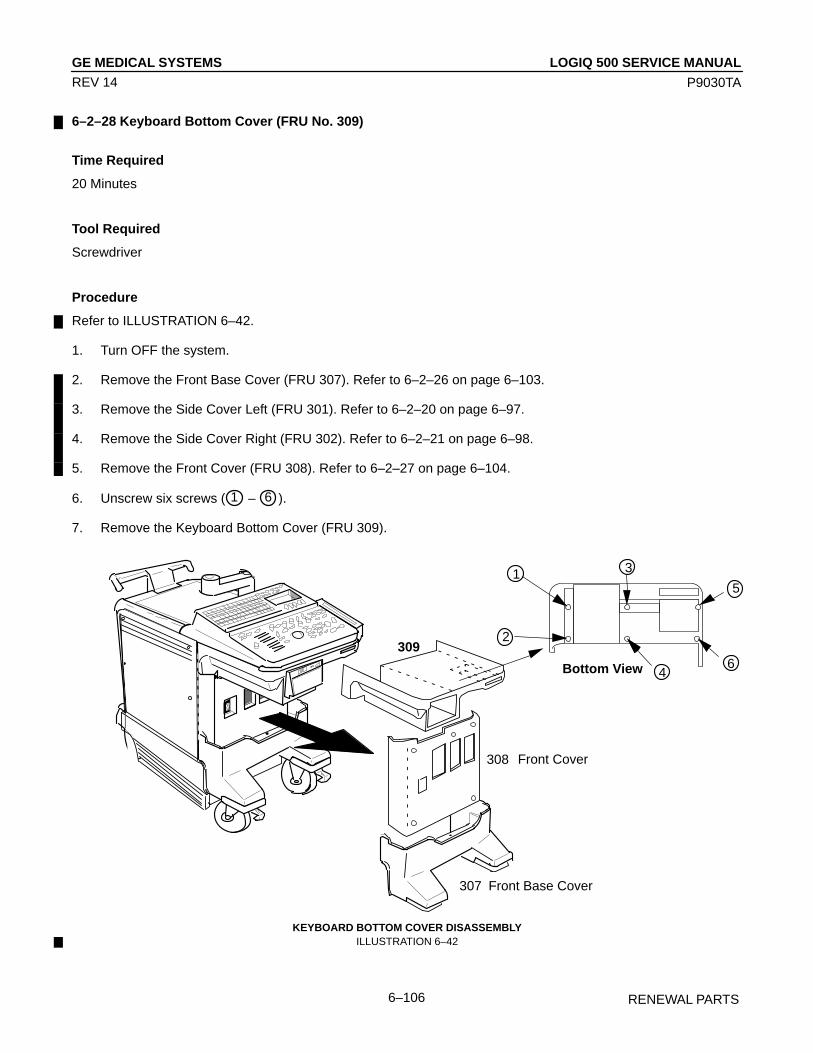
LOGIQ 500 SERVICE MANUALGE MEDICAL SYSTEMS
P9030TA
RENEWAL PARTS6–106
REV 14
6–2–28 Keyboard Bottom Cover (FRU No. 309)
Time Required
20 Minutes
Tool Required
Screwdriver
Procedure
Refer to ILLUSTRATION 6–42.
1. Turn OFF the system.
2. Remove the Front Base Cover (FRU 307). Refer to 6–2–26 on page 6–103.
3. Remove the Side Cover Left (FRU 301). Refer to 6–2–20 on page 6–97.
4. Remove the Side Cover Right (FRU 302). Refer to 6–2–21 on page 6–98.
5. Remove the Front Cover (FRU 308). Refer to 6–2–27 on page 6–104.
6. Unscrew six screws ( 1 – 6 ).
7. Remove the Keyboard Bottom Cover (FRU 309).
309
Î
ÎÎ
ÎÎÎ
ÎÎÎÎ
ÎÎÎ
ÎÎÎÎÎÎÎÎÎÎÎÎÎÎÎÎÎÎÎÎÎÎÎÎÎÎÎÎ
ÎÎÎÎÎÎÎÎÎÎÎÎ
ÎÎÎÎÎÎ
ÎÎÎÎÎÎÎÎÎÎ
ÎÎÎÎÎÎÎÎÎÎÎÎÎÎÎ
ÎÎÎÎÎÎÎÎÎÎÎÎÎÎÎÎ
ÎÎ
ÎÎÎÎÎÎÎÎÎÎÎÎÎÎÎÎÎÎÎÎÎ
ÎÎÎÎÎÎÎÎÎÎÎÎÎÎÎÎÎÎÎÎÎÎÎÎÎÎÎÎÎÎÎÎÎÎÎÎÎÎÎÎ
ÎÎ
ÎÎÎÎ
ÎÎÎÎÎÎÎ
ÎÎÎÎÎÎÎÎÎÎÎÎÎÎÎÎÎÎÎÎÎÎÎÎ
ÎÎÎÎÎÎÎÎÎÎÎÎÎÎÎÎÎÎÎÎÎÎÎÎ
ÎÎÎÎÎÎÎÎÎÎÎÎ
ÎÎÎÎÎÎÎ
ÎÎÎÎÎÎÎÎÎÎÎÎÎÎÎÎÎÎÎÎÎÎÎÎÎÎÎÎÎÎÎÎÎÎÎ
ÎÎÎ
Î
ÎÎ
Î
307 Front Base Cover
308 Front Cover
ÎÎÎÎÎÎÎÎÎÎÎÎÎÎÎÎÎÎÎÎÎÎÎÎÎÎÎÎÎÎÎÎÎÎÎÎÎÎÎÎÎÎÎÎÎ
1
2
3
5ÎÎÎÎÎÎÎÎÎÎÎÎÎÎÎÎÎÎÎÎÎÎÎÎÎÎÎÎÎÎÎÎÎÎÎÎÎÎÎÎÎÎÎÎÎÎÎÎÎÎÎÎÎÎ
ÎÎÎÎÎÎÎÎÎÎÎÎÎÎÎÎÎÎÎÎÎÎÎÎÎÎÎ
ÎÎÎÎÎÎÎÎÎÎÎÎ
ÎÎÎÎÎÎÎÎ
ÎÎÎÎÎÎ
ÎÎÎÎÎÎ
ÎÎÎÎÎÎÎ Î Î
Î Î ÎÎBottom View 6
4
ÎÎÎÎÎÎÎÎÎÎÎÎÎÎÎÎÎÎÎÎÎÎÎÎÎÎÎÎÎÎÎÎÎÎÎÎÎÎÎÎÎÎÎÎÎÎÎÎÎÎÎÎÎÎÎÎÎÎÎÎÎÎÎÎÎÎ
ÎÎ
Î
Î
ÎÎÎ
ÎÎÎÎ
ÎÎ
ÎÎÎÎÎÎÎÎÎÎÎÎÎÎÎÎÎÎÎÎÎÎÎÎÎÎÎÎÎÎÎÎ
ÎÎÎÎÎÎÎÎÎÎÎÎÎÎÎÎÎÎÎÎÎÎÎÎ
KEYBOARD BOTTOM COVER DISASSEMBLYILLUSTRATION 6–42

LOGIQ 500 SERVICE MANUALGE MEDICAL SYSTEMS
P9030TA
RENEWAL PARTS6–107
REV 14
This page is left blank intentionally.
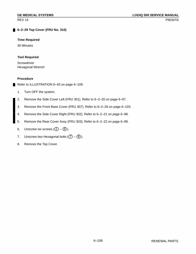
LOGIQ 500 SERVICE MANUALGE MEDICAL SYSTEMS
P9030TA
RENEWAL PARTS6–108
REV 14
6–2–29 Top Cover (FRU No. 310)
Time Required
30 Minutes
Tool Required
ScrewdriverHexagonal Wrench
Procedure
Refer to ILLUSTRATION 6–43 on page 6–109.
1. Turn OFF the system.
2. Remove the Side Cover Left (FRU 301). Refer to 6–2–20 on page 6–97.
3. Remove the Front Base Cover (FRU 307). Refer to 6–2–26 on page 6–103.
4. Remove the Side Cover Right (FRU 302). Refer to 6–2–21 on page 6–98.
5. Remove the Rear Cover Assy (FRU 303). Refer to 6–2–22 on page 6–99.
6. Unscrew six screws ( 1 – 6 ).
7. Unscrew two Hexagonal bolts ( 7 – 8 ).
8. Remove the Top Cover.

LOGIQ 500 SERVICE MANUALGE MEDICAL SYSTEMS
P9030TA
RENEWAL PARTS6–109
REV 14
6–2–29 Top Cover (FRU No. 310) (continued)
Î
ÎÎ
ÎÎÎÎÎÎÎÎ
ÎÎÎÎÎÎ
ÎÎÎÎÎÎÎÎÎÎÎÎÎÎÎÎÎÎÎÎÎÎÎÎÎÎÎÎ
ÎÎÎÎÎÎÎÎÎÎÎÎ
ÎÎÎÎÎÎÎÎÎÎ
ÎÎÎÎ
ÎÎÎÎ
ÎÎÎÎÎÎÎÎÎÎÎÎÎÎÎ
ÎÎÎÎÎÎÎÎ
ÎÎÎÎÎÎ
ÎÎÎÎÎÎÎÎÎ
ÎÎÎ
ÎÎÎÎÎÎÎÎÎÎÎÎ
ÎÎÎÎÎÎÎÎÎÎÎÎÎÎÎÎÎÎÎÎÎÎÎÎÎÎÎÎÎÎÎÎÎÎÎÎÎÎÎÎÎÎÎÎÎÎÎÎÎÎÎÎÎ
Î
ÎÎÎ
ÎÎÎÎÎÎÎÎÎÎÎÎÎÎÎ
ÎÎÎÎ
ÎÎÎÎÎÎÎÎÎÎÎÎÎÎÎÎÎÎÎÎÎÎÎÎÎÎÎÎÎÎÎÎÎÎÎÎÎÎÎ
ÎÎÎÎÎÎÎÎ
ÎÎÎÎÎÎÎÎÎÎÎ
ÎÎÎÎÎÎÎÎÎÎÎÎÎÎÎÎÎÎÎÎÎÎÎÎÎÎÎÎÎÎÎÎÎÎÎÎÎÎÎÎ
Î
1
2
310
ÎÎÎÎÎÎÎÎÎÎÎÎÎÎÎÎÎÎÎÎÎÎÎÎÎÎÎÎÎÎÎÎÎÎÎÎÎÎÎÎÎÎÎÎÎÎÎÎÎÎÎÎÎÎÎÎÎÎÎÎÎÎÎÎÎÎÎÎÎÎÎÎ
Î
Î
Î
ÎÎ
ÎÎÎÎÎÎ
ÎÎÎÎ
ÎÎÎÎÎÎÎÎÎÎÎÎÎÎÎÎÎÎÎÎÎÎÎÎÎÎÎÎÎÎÎ
ÎÎÎÎÎÎÎÎÎÎÎÎÎÎÎÎÎÎÎÎÎÎÎÎÎÎÎÎÎÎÎÎÎÎÎ
ÎÎ
ÎÎ Î
ÎÎÎ
ÎÎÎÎÎÎ
ÎÎ
Î
ÎÎÎÎÎÎ
ÎÎÎÎÎÎÎÎÎÎÎÎÎÎÎÎÎÎÎÎÎ
ÎÎ
ÎÎÎÎÎÎÎÎÎÎÎÎÎÎÎÎÎÎÎÎÎÎÎÎÎÎÎÎÎÎÎÎÎÎÎÎÎÎÎÎÎÎÎÎÎÎÎÎÎÎÎÎÎÎÎÎÎÎÎÎÎÎÎÎÎÎÎÎÎÎÎÎ
ÎÎÎÎÎÎ
ÎÎÎÎÎ
ÎÎ
3
4
5 6
ÎÎÎÎ
ÎÎÎ
ÎÎÎ
ÎÎ
ÎÎÎÎÎÎÎÎÎÎÎ
ÎÎÎÎÎ
ÎÎÎÎ
ÎÎÎ
ÎÎÎÎÎÎ
ÎÎÎÎÎ
ÎÎ
Î 7
8
ÎÎ
307 Front Base Cover301 Side Cover Left
302 Side Cover Right
Right Side View
TOP COVER DISASSEMBLYILLUSTRATION 6–43
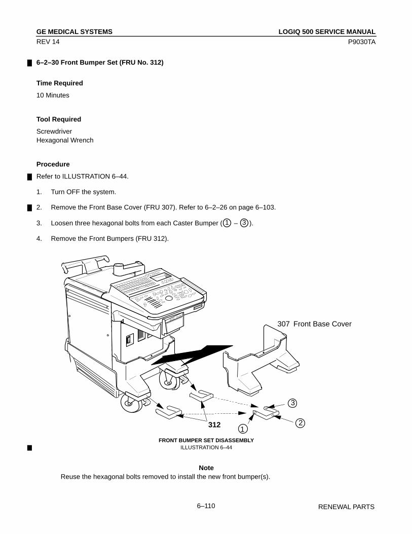
LOGIQ 500 SERVICE MANUALGE MEDICAL SYSTEMS
P9030TA
RENEWAL PARTS6–110
REV 14
6–2–30 Front Bumper Set (FRU No. 312)
Time Required
10 Minutes
Tool Required
ScrewdriverHexagonal Wrench
Procedure
Refer to ILLUSTRATION 6–44.
1. Turn OFF the system.
2. Remove the Front Base Cover (FRU 307). Refer to 6–2–26 on page 6–103.
3. Loosen three hexagonal bolts from each Caster Bumper ( 1 – 3 ).
4. Remove the Front Bumpers (FRU 312).
ÎÎ
ÎÎÎ
ÎÎÎÎ
ÎÎÎÎÎÎ
ÎÎÎÎÎÎÎÎ
ÎÎÎÎÎÎÎÎÎÎÎÎÎÎÎÎÎÎÎÎÎÎÎÎÎÎÎÎÎÎÎÎÎÎÎÎÎÎÎÎ
ÎÎÎÎÎÎÎÎÎÎÎÎÎÎÎ
ÎÎÎÎÎÎÎ
ÎÎÎÎÎÎÎÎÎÎ
ÎÎÎÎÎÎÎÎÎÎÎÎÎÎÎ
ÎÎÎÎÎÎÎÎ
ÎÎÎÎÎÎÎÎ
ÎÎÎÎÎÎÎÎÎ
ÎÎÎ
ÎÎÎÎÎÎÎÎÎÎÎÎ
ÎÎÎÎÎÎÎÎÎÎÎÎÎÎÎÎÎÎÎÎÎÎÎÎÎÎÎÎÎÎÎÎÎÎÎÎÎÎÎÎÎÎÎÎÎÎÎÎÎÎÎÎÎÎÎÎÎÎÎÎÎÎÎÎÎÎÎÎ
Î
ÎÎÎÎÎ
ÎÎÎÎ
ÎÎÎÎÎÎÎÎÎÎÎÎÎ
ÎÎÎÎÎ
ÎÎÎÎÎÎÎÎÎÎÎÎÎÎÎÎÎÎÎÎÎÎÎÎÎÎÎÎÎÎÎÎÎÎÎÎÎÎ
ÎÎÎÎÎÎÎÎÎ
ÎÎÎÎÎÎÎÎÎÎÎÎ
307 Front Base Cover
ÎÎÎÎÎÎ
ÎÎÎÎÎÎ
312
ÎÎÎÎÎÎÎÎ
Î1
2
3
ÎÎÎÎÎÎÎÎÎÎÎÎÎÎÎÎÎÎÎÎÎÎÎÎÎÎÎÎÎÎÎÎÎÎÎÎÎÎÎÎÎÎÎÎÎÎÎÎÎÎÎÎÎÎÎÎÎÎÎÎÎÎÎÎÎÎÎÎÎÎÎÎ
Î
Î
Î
ÎÎ
ÎÎÎÎÎÎÎÎ
ÎÎÎÎ
ÎÎÎÎÎÎÎÎÎÎÎÎÎÎÎÎÎÎÎÎÎÎÎÎÎÎÎÎÎÎÎ
ÎÎÎÎÎÎÎÎÎÎÎÎÎÎÎÎÎÎÎÎÎÎÎÎÎÎÎÎÎÎÎÎÎÎÎ
FRONT BUMPER SET DISASSEMBLYILLUSTRATION 6–44
NoteReuse the hexagonal bolts removed to install the new front bumper(s).
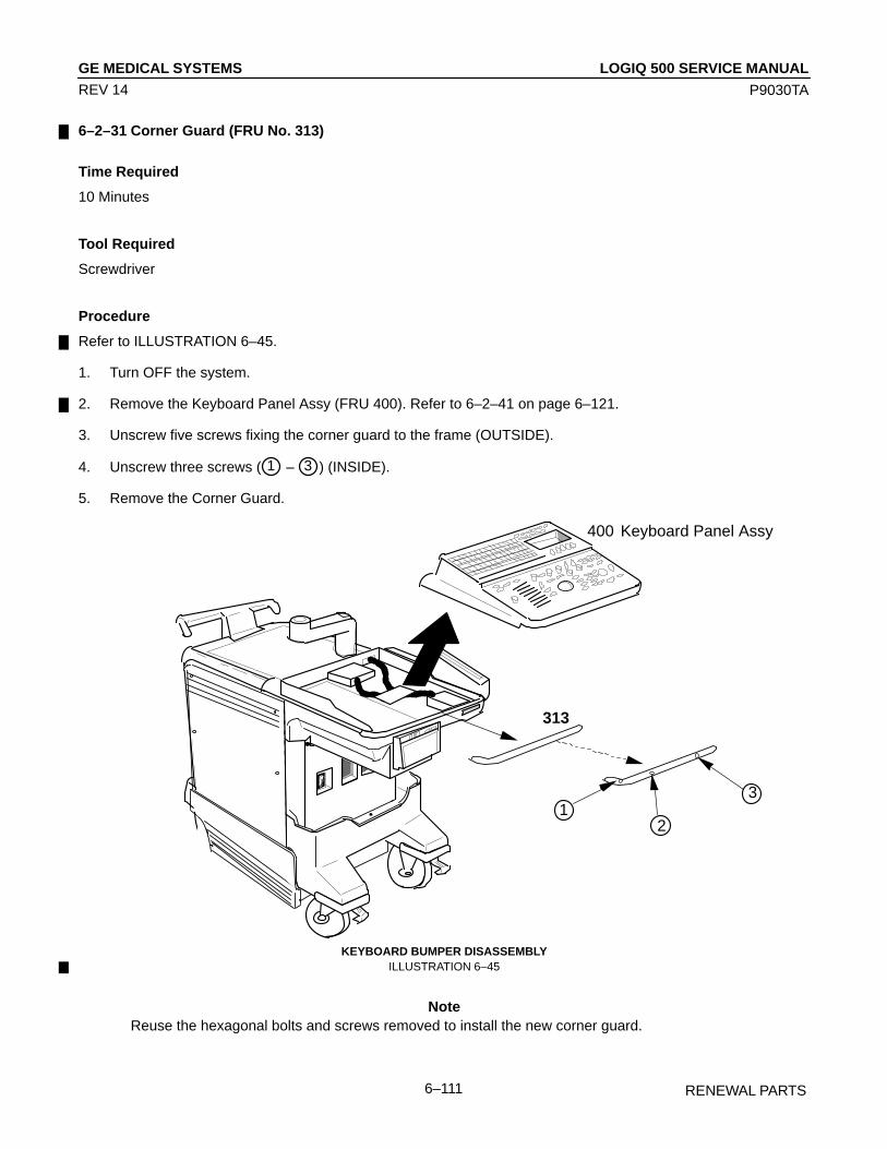
LOGIQ 500 SERVICE MANUALGE MEDICAL SYSTEMS
P9030TA
RENEWAL PARTS6–111
REV 14
6–2–31 Corner Guard (FRU No. 313)
Time Required
10 Minutes
Tool Required
Screwdriver
Procedure
Refer to ILLUSTRATION 6–45.
1. Turn OFF the system.
2. Remove the Keyboard Panel Assy (FRU 400). Refer to 6–2–41 on page 6–121.
3. Unscrew five screws fixing the corner guard to the frame (OUTSIDE).
4. Unscrew three screws ( 1 – 3 ) (INSIDE).
5. Remove the Corner Guard.
ÎÎ
ÎÎ
ÎÎÎÎÎÎÎÎÎ
ÎÎÎÎÎÎÎÎ
ÎÎÎÎÎÎÎÎÎÎÎÎÎÎÎÎÎÎÎÎÎÎÎÎÎÎÎÎÎÎÎÎÎÎÎÎÎÎÎÎ
ÎÎÎÎÎÎÎÎÎÎÎÎÎÎÎ
ÎÎÎÎÎÎÎ
ÎÎ
ÎÎÎÎÎÎ
ÎÎÎÎÎÎÎÎÎÎÎÎÎÎÎ
ÎÎÎÎÎÎÎÎÎÎÎÎÎÎÎÎÎÎ
ÎÎÎ
ÎÎÎÎÎÎÎÎÎÎÎÎ
ÎÎÎ
ÎÎÎÎÎÎÎÎÎÎÎÎÎÎÎÎÎÎÎÎÎÎÎÎÎÎÎÎÎÎÎÎÎÎÎÎÎÎÎÎÎÎÎÎÎÎÎÎÎÎÎÎÎÎÎÎÎÎÎÎÎÎÎÎÎÎ
Î
ÎÎÎÎ
ÎÎÎÎÎÎÎÎ
ÎÎÎÎÎÎÎÎÎÎÎÎÎÎÎÎÎÎÎÎÎÎÎ
ÎÎÎÎÎÎÎÎÎÎÎÎÎÎ
ÎÎÎÎÎÎÎÎÎÎÎÎ
ÎÎÎÎÎÎÎÎÎÎÎÎ
ÎÎÎÎÎÎÎ
ÎÎ
ÎÎÎÎÎÎÎÎÎÎÎÎÎÎÎÎÎÎ
ÎÎÎÎÎÎÎÎÎÎÎÎÎÎÎÎÎÎÎ
ÎÎÎ
12
3
400 Keyboard Panel Assy
313
ÎÎÎÎÎÎÎÎÎÎÎÎÎÎÎÎÎÎÎÎÎÎÎÎÎÎÎÎÎÎÎÎÎÎÎÎÎÎÎÎÎÎÎÎÎÎÎÎÎÎÎÎÎÎÎÎÎÎÎÎÎÎÎÎÎÎÎÎÎÎÎÎ
ÎÎ
Î
Î
ÎÎ
Î
ÎÎÎÎÎÎÎÎ
ÎÎ
ÎÎÎÎÎÎÎÎÎÎÎÎÎÎÎÎÎÎÎÎÎÎÎÎÎÎÎÎÎÎÎ
ÎÎÎÎÎÎÎÎÎÎÎÎÎÎÎÎÎÎÎÎÎÎÎÎÎÎÎÎÎÎÎÎÎÎÎ
KEYBOARD BUMPER DISASSEMBLYILLUSTRATION 6–45
NoteReuse the hexagonal bolts and screws removed to install the new corner guard.

LOGIQ 500 SERVICE MANUALGE MEDICAL SYSTEMS
P9030TA
RENEWAL PARTS6–112
REV 14
6–2–32 Probe Holder (FRU No. 314)
Time Required
1 Minutes
Tool Required
Not necessary
Procedure
Refer to ILLUSTRATION 6–46.
1. Turn OFF the system.
2. Pull the latch located at bottom of the probe holder.
3. Pull the Probe Holder out as shown in ILLUSTRATION 6–46.
ÎÎÎÎÎÎÎÎÎÎÎÎÎÎÎ
ÎÎ
ÎÎÎ
ÎÎÎÎÎ
ÎÎÎÎÎÎÎÎ
ÎÎÎÎÎÎ
ÎÎÎÎÎÎÎÎÎÎÎÎÎÎÎÎÎÎÎÎÎÎÎÎÎÎÎÎÎÎÎÎÎÎÎ
ÎÎÎÎÎÎÎÎÎÎÎ
ÎÎÎÎÎ
ÎÎÎÎÎÎÎÎ
ÎÎÎÎÎÎÎÎÎÎÎÎÎÎÎÎÎÎÎÎ
ÎÎÎÎÎÎÎÎÎÎ
ÎÎÎÎÎÎÎÎ
ÎÎÎÎÎÎ
ÎÎÎÎÎÎÎÎÎÎÎÎÎÎÎÎÎÎÎÎÎÎ
ÎÎÎÎÎÎÎÎÎÎÎÎÎÎÎÎÎÎÎÎÎÎÎÎÎÎÎÎÎÎÎÎÎÎÎÎÎÎÎÎÎÎÎÎÎÎÎÎÎÎ
ÎÎ
ÎÎÎÎÎÎ
Î
ÎÎÎÎÎÎÎÎÎÎÎÎÎÎ
ÎÎ
ÎÎÎÎÎÎÎÎÎÎÎ
ÎÎÎÎÎÎÎÎÎÎÎÎÎ
ÎÎÎÎÎÎÎÎÎÎÎÎÎÎÎÎÎÎÎ
ÎÎÎÎÎÎÎÎ
ÎÎÎÎÎÎÎÎÎÎÎÎ
ÎÎÎÎÎÎÎÎÎÎÎÎÎÎÎÎÎÎÎÎÎÎÎÎÎÎÎÎÎÎÎÎÎÎÎÎÎÎÎÎÎÎÎÎÎÎÎÎÎÎÎÎÎÎÎÎÎÎÎÎÎÎÎÎÎÎ
Î
ÎÎ
Î
ÎÎ
Î
ÎÎÎÎÎÎÎÎ
Î
ÎÎÎÎÎÎÎÎÎÎÎÎÎÎÎÎÎÎÎÎÎÎÎÎÎÎ
ÎÎÎÎÎÎÎÎÎÎÎÎÎÎÎÎÎÎÎÎÎÎÎÎÎÎÎÎÎÎÎÎÎÎÎ
314
PROBE HOLDER DISASSEMBLYILLUSTRATION 6–46
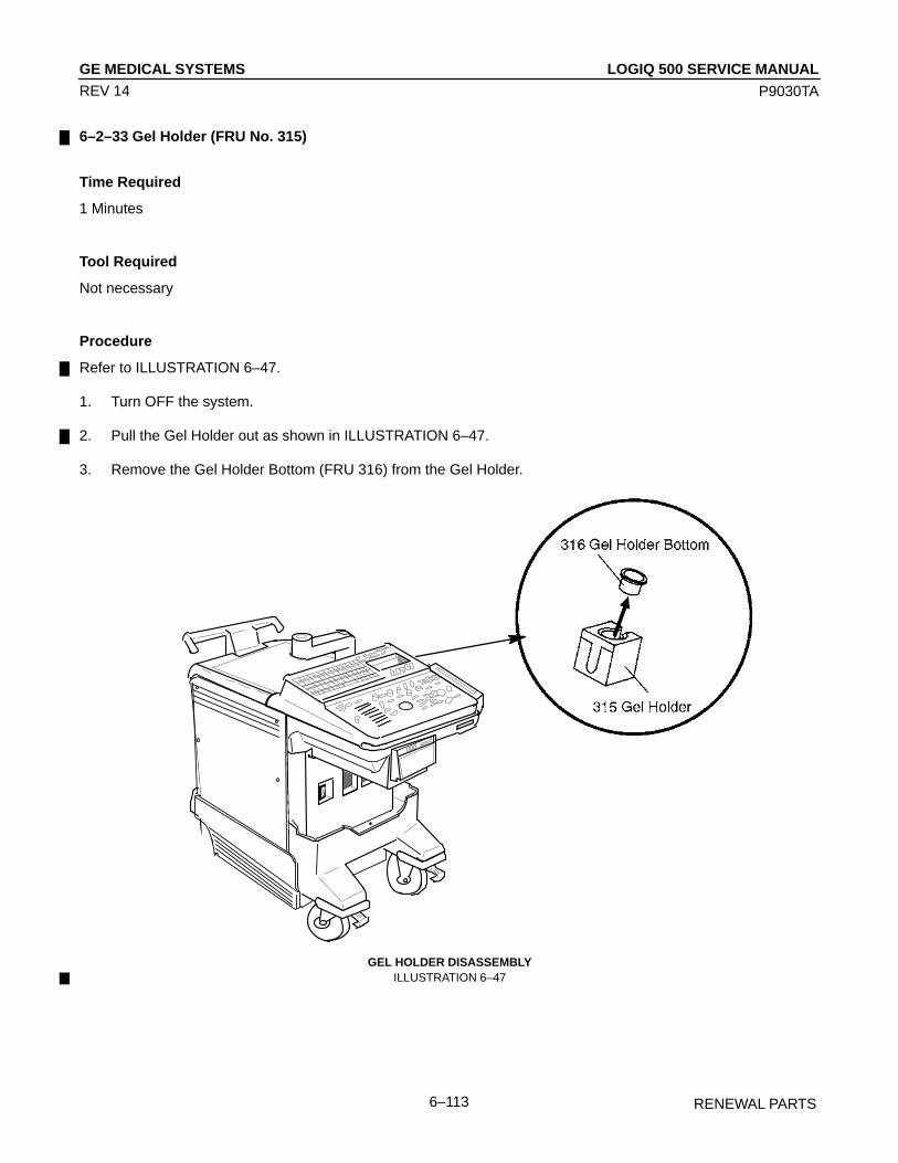
LOGIQ 500 SERVICE MANUALGE MEDICAL SYSTEMS
P9030TA
RENEWAL PARTS6–113
REV 14
6–2–33 Gel Holder (FRU No. 315)
Time Required
1 Minutes
Tool Required
Not necessary
Procedure
Refer to ILLUSTRATION 6–47.
1. Turn OFF the system.
2. Pull the Gel Holder out as shown in ILLUSTRATION 6–47.
3. Remove the Gel Holder Bottom (FRU 316) from the Gel Holder.
ÎÎ
ÎÎÎÎ
Î
ÎÎÎ
ÎÎÎÎÎÎÎÎ
ÎÎÎÎÎÎ
ÎÎÎÎÎÎÎÎÎÎÎÎÎÎÎÎÎÎÎÎÎÎÎÎÎÎÎÎ
ÎÎÎÎÎÎÎÎÎÎÎÎÎ
ÎÎÎÎÎ
ÎÎÎÎÎÎÎÎÎÎ
ÎÎÎÎÎÎÎÎÎÎÎÎÎÎÎÎÎÎÎÎ
ÎÎÎÎÎÎÎ
ÎÎÎÎÎÎÎÎ
ÎÎÎÎÎÎ
ÎÎÎÎÎÎÎÎÎÎÎÎÎÎÎÎÎÎÎÎÎÎÎÎÎÎ
ÎÎÎÎÎÎÎÎÎÎÎÎÎÎÎÎÎÎÎÎÎÎÎÎÎÎÎÎÎÎÎÎÎÎÎÎÎÎÎÎÎÎÎÎÎÎÎÎÎÎÎÎÎÎÎ
Î
ÎÎÎÎ
ÎÎÎÎÎ
ÎÎÎÎÎÎ Î
ÎÎÎÎÎ
ÎÎÎÎÎÎÎÎÎÎÎÎÎÎ
ÎÎÎÎÎÎÎÎÎÎÎÎÎÎÎÎÎÎÎÎ
ÎÎÎÎÎÎÎÎÎ
ÎÎÎÎÎÎÎÎÎÎÎÎÎÎÎÎÎÎÎÎÎÎ
ÎÎÎÎÎÎÎÎÎÎÎÎÎÎÎÎÎÎÎÎÎÎÎÎÎÎÎÎÎÎÎÎÎÎÎÎÎÎÎÎÎÎÎÎÎÎÎÎÎÎÎÎÎÎÎÎÎÎÎÎÎÎÎÎÎÎ
Î
Î
Î
ÎÎ
Î
ÎÎÎÎÎÎ
ÎÎÎÎ
ÎÎÎÎÎÎÎÎÎÎÎÎÎÎÎÎÎÎÎÎÎÎÎÎÎÎÎÎÎÎÎ
ÎÎÎÎÎÎÎÎÎÎÎÎÎÎÎÎÎÎÎÎÎÎÎÎÎÎÎÎÎÎÎÎÎÎÎ
GEL HOLDER DISASSEMBLYILLUSTRATION 6–47
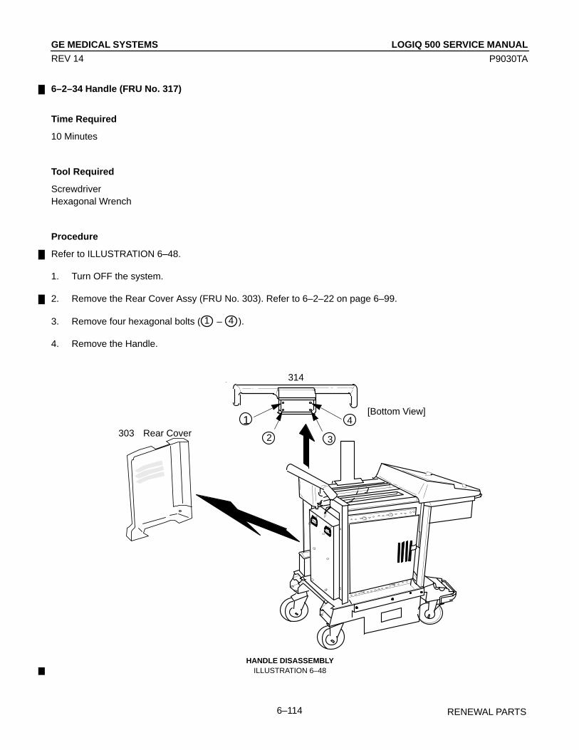
LOGIQ 500 SERVICE MANUALGE MEDICAL SYSTEMS
P9030TA
RENEWAL PARTS6–114
REV 14
6–2–34 Handle (FRU No. 317)
Time Required
10 Minutes
Tool Required
ScrewdriverHexagonal Wrench
Procedure
Refer to ILLUSTRATION 6–48.
1. Turn OFF the system.
2. Remove the Rear Cover Assy (FRU No. 303). Refer to 6–2–22 on page 6–99.
3. Remove four hexagonal bolts ( 1 – 4 ).
4. Remove the Handle.
1
2 3
4
314
303 Rear Cover
[Bottom View]
HANDLE DISASSEMBLYILLUSTRATION 6–48
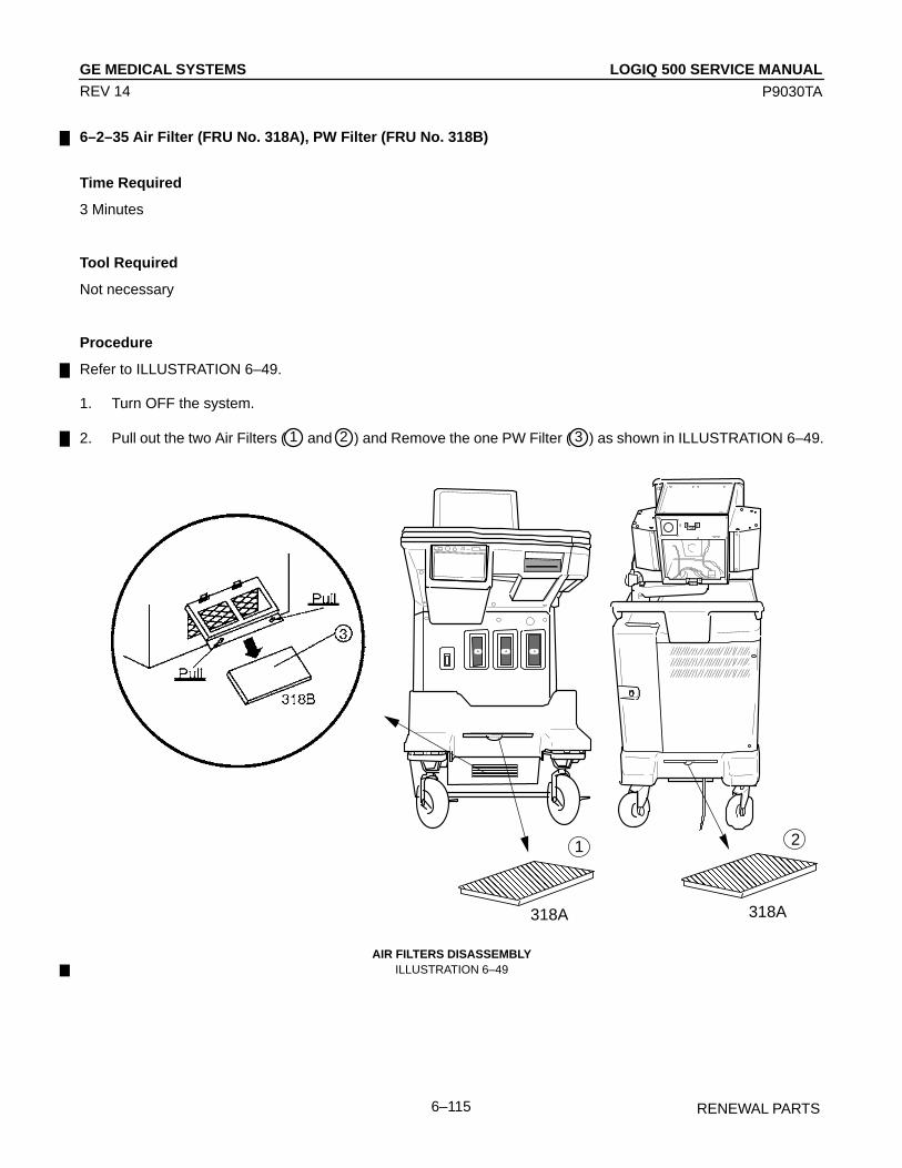
LOGIQ 500 SERVICE MANUALGE MEDICAL SYSTEMS
P9030TA
RENEWAL PARTS6–115
REV 14
6–2–35 Air Filter (FRU No. 318A), PW Filter (FRU No. 318B)
Time Required
3 Minutes
Tool Required
Not necessary
Procedure
Refer to ILLUSTRATION 6–49.
1. Turn OFF the system.
2. Pull out the two Air Filters ( 1 and 2 ) and Remove the one PW Filter ( 3 ) as shown in ILLUSTRATION 6–49.
ÎÎÎ
ÎÎÎ ÎÎÎÎÎÎÎÎÎ
ÎÎÎÎÎÎÎÎÎÎÎÎÎÎÎÎ
Î Î
ÎÎ
Î ÎÎÎÎÎÎ
ÎÎÎÎÎÎ ÎÎÎ
Î
ÎÎÎÎ
ÎÎÎ
ÎÎÎÎ
ÎÎ
ÎÎ
ÎÎÎÎÎÎÎÎÎÎÎÎÎÎÎ
ÎÎÎÎÎÎÎÎÎÎ
ÎÎÎÎÎÎÎÎÎÎÎÎÎÎÎÎÎÎÎÎÎ
ÌÌÌÌÌÌÌÌÌÌÌÌÌÌ
ÎÎÎÎÎÎÎÎÎÎÎÎÎÎ
ÌÌÌÌÌÌÌÌÌÌÌÌÌÌÌÌÌÌÌÌÌ
Î
ÎÎÎ
ÎÎÎÎÎÎÎ
ÎÎ
ÎÎÎ
Î
ÎÎ
ÎÎÎ
ÎÎÎÎÎÎÎ
Î
ÏÏÏÏÏÏ
318A
21
318A
AIR FILTERS DISASSEMBLYILLUSTRATION 6–49
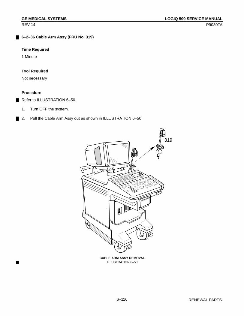
LOGIQ 500 SERVICE MANUALGE MEDICAL SYSTEMS
P9030TA
RENEWAL PARTS6–116
REV 14
6–2–36 Cable Arm Assy (FRU No. 319)
Time Required
1 Minute
Tool Required
Not necessary
Procedure
Refer to ILLUSTRATION 6–50.
1. Turn OFF the system.
2. Pull the Cable Arm Assy out as shown in ILLUSTRATION 6–50.
ÎÎÎÎÎÎÎÎ
Î
ÎÎÎÎÎ
ÎÎÎÎÎÎÎÎÎÎÎÎÎÎÎ
ÎÎÎÎÎÎ
ÎÎÎÎÎÎÎÎÎÎÎÎÎÎÎÎÎÎÎÎÎÎÎÎ
ÎÎÎÎÎÎÎÎÎÎÎÎÎ
ÎÎÎ
ÎÎ
ÎÎÎÎÎÎÎÎÎÎ
ÎÎÎÎÎÎÎÎÎÎÎÎÎÎÎÎ
ÎÎÎÎÎÎÎ
ÎÎÎÎÎÎÎÎÎÎÎÎÎÎÎÎÎÎÎÎÎÎÎÎÎÎÎÎ
ÎÎÎÎÎÎ
ÎÎÎÎÎÎ
ÎÎÎÎÎÎÎÎÎÎÎÎÎÎÎÎÎÎÎÎÎÎÎÎÎÎÎÎ
ÎÎÎÎÎÎÎÎÎ
ÎÎÎÎÎ
ÎÎÎÎ
ÎÎÎÎÎÎ
ÎÎÎÎÎÎÎÎÎÎÎÎÎÎÎ
ÎÎÎÎÎÎÎÎÎÎ
ÎÎÎÎÎÎÎÎÎÎ
ÎÎÎÎÎÎÎÎÎÎÎÎÎÎÎÎÎÎÎÎÎÎÎÎÎÎÎÎÎÎÎÎÎÎÎÎÎÎÎÎÎÎÎÎÎÎÎÎÎÎÎÎÎÎÎÎÎÎÎÎÎÎÎÎÎÎ
Î
ÎÎÎÎ
Î
Î
ÎÎÎÎ
ÎÎ
ÎÎÎÎÎÎÎÎÎÎÎÎÎÎÎÎÎÎÎÎÎÎÎÎÎÎÎÎÎÎÎÎÎÎÎÎÎ
Î
319
CABLE ARM ASSY REMOVALILLUSTRATION 6–50

LOGIQ 500 SERVICE MANUALGE MEDICAL SYSTEMS
P9030TA
RENEWAL PARTS6–117
REV 14
6–2–37 Cable Arm Knob (FRU No. 320)
Time Required
1 Minutes
Tool Required
Not necessary
Procedure
Refer to ILLUSTRATION 6–51.
1. Turn OFF the system.
2. Turn each Cable Arm Knob counterclockwise and remove it.
CABLE ARM KNOB REMOVALILLUSTRATION 6–51

LOGIQ 500 SERVICE MANUALGE MEDICAL SYSTEMS
P9030TA
RENEWAL PARTS6–118
REV 14
6–2–38 Front Caster (FRU No. 321)
Time Required
15 Minutes
Tool Required
ScrewdriverHexagonal Wrench
Procedure
Refer to ILLUSTRATION 6–52.
1. Turn OFF the system.
2. Put the system on a box.
3. Remove the Caster Covers (FRU 323). Refer to 6–2–40 on page 6–120.
4. Unscrew four hexagonal bolts ( 1 – 4 ) and remove the Front Caster.
ÎÎ
ÎÎ
ÎÎÎÎ
ÎÎÎÎ
ÎÎÎÎÎÎ
ÎÎÎÎ
Î
ÎÎÎ
ÎÎÎÎÎÎÎ Î
Î
ÎÎÎÎÎÎÎÎÎÎÎÎÎÎÎÎÎÎÎ
ÎÎÎÎÎÎÎÎÎÎÎÎ
1
2 3
4ÎÎÎÎÎÎ
ÎÎÎÎÎÎÎÎÎÎÎÎÎÎÎÎÎ
ÎÎÎÎÎÎ
ÎÎÎÎ
ÎÎÎÎÎÎ
ÎÎ
ÎÎ
ÎÎÎÎÎÎ
ÎÎ
Î
Î
ÎÎÎ
ÎÎ
ÎÎÎÎÎÎÎÎÎ
Î
Box
321323 Caster Cover
FRONT CASTER DISASSEMBLYILLUSTRATION 6–52

LOGIQ 500 SERVICE MANUALGE MEDICAL SYSTEMS
P9030TA
RENEWAL PARTS6–119
REV 14
6–2–39 Rear Caster (FRU No. 322)
Time Required
15 Minutes
Tool Required
ScrewdriverHexagonal Wrench
Procedure
Refer to ILLUSTRATION 6–53.
1. Turn OFF the system.
2. Put the system on a box.
3. Remove the Caster Covers (FRU 323). Refer to 6–2–40 on page 6–120.
4. Unscrew four screws ( 1 – 4 ) and remove the Rear Caster.
ÎÎÎÎ
ÎÎÎ ÎÎÎÎÎÎÎÎÎÎ
ÎÎÎÎÎÎÎÎÎÎÎÎÎÎ
ÎÎÎÎÎÎ
ÎÎ
ÎÎ
ÎÎÎÎÎÎÎÎÎ
ÎÎÎÎÎÎ ÎÎ
ÎÎ
ÎÎ
ÎÎÎÎ
ÎÎÎÎÎÎ
Î
ÎÎ
ÎÎÎÎÎÎÎÎÎÎÎÎÎÎÎ
ÎÎÎÎÎÎÎ
ÎÎ
ÎÎÎÎÎÎÎÎÎÎÎÎÎ ÎÎÎ
ÎÎÎÎÎÎÎÎÎÎÎÎÎ
ÎÎÎÎÎÎÎÎÎÎ ÎÎÎ
ÎÎÎÎÎÎÎÎÎÎ
ÎÎÎ
ÎÎÎÎÎ ÎÎÎÎÎÎÎÎÎ
ÎÎÎÎÎÎÎÎÎÎÎÎÎ
ÎÎ
ÎÎÎ Î
ÎÎÎ
Î ÎÎÎÎÎÎ
ÎÎÎÎÎÎ ÎÎ
Î
Î
ÎÎ ÎÎÎÎ
ÎÎÎÎÎÎÎÎÎÎÎÎÎÎÎÎÎÎÎÎÎ
ÎÎÎÎÎÎÎÎ
Î
ÎÎÎÎ
ÎÎÎÎÎÎÎÎÎÎÎÎÎÎÎÎ
1
2
3322
Box
4
323 Caster Cover323 Caster Cover
REAR CASTER DISASSEMBLYILLUSTRATION 6–53

LOGIQ 500 SERVICE MANUALGE MEDICAL SYSTEMS
P9030TA
RENEWAL PARTS6–120
REV 14
6–2–40 Caster Cover Set (FRU No. 323)
Time Required
15 Minutes
Tool Required
Screwdriver
Procedure
Refer to ILLUSTRATION 6–54.
1. Turn OFF the system.
2. Unscrew five screws ( 1 – 5 ).
3. Remove the Caster Covers.
ÎÎÎÎÎÎÎÎÎÎÎÎÎÎÎÎ
ÎÎÎÎÎÎÎÎÎÎÎ
ÎÎÎÎÎÎÎÎÎÎÎÎÎÎÎÎÎÎÎÎ
ÎÎÎÎÎÎÎÎÎÎÎÎ
ÎÎÎÎÎÎÎÎÎÎÎÎÎÎÎ
ÎÎÎÎÎ
ÎÎÎÎÎÎÎÎÎÎÎÎÎ
ÎÎÎÎÎÎÎÎÎÎÎÎ
ÎÎÎÎÎÎÎÎÎÎÎÎÎ
ÎÎÎÎÎÎ
ÎÎ
ÎÎÎÎÎÎ
ÎÎÎÎÎÎÎÎÎÎ
ÎÎÎÎ
ÎÎÎ
ÎÎÎÎ ÎÎÎ
ÎÎÎÎÎÎÎ
ÎÎÎÎÎÎÎÎÎÎÎÎÎÎÎ Î
ÎÎÎÎÎÎÎÎÎÎ
ÎÎÎÎÎÎ ÎÎ
Î
ÎÎ
ÎÎÎÎÎÎÎÎÎÎÎÎÎÎÎÎÎ
ÎÎÎÎÎÎÎ
ÎÎÎÎÎÎÎÎÎÎÎÎÎÎÎÎÎ
ÎÎÎÎÎÎÎÎÎÎ
1
2
3
4
5
ÎÎ
ÎÎ
ÎÎÎÎÎÎ
ÎÎÎ
ÎÎÎ
ÎÎÎÎ
ÎÎÎÎÎÎÎÎ
ÎÎÎÎÎÎÎÎÎ
323
323 323 323 323
CASTER COVERS DISASSEMBLYILLUSTRATION 6–54

LOGIQ 500 SERVICE MANUALGE MEDICAL SYSTEMS
P9030TA
RENEWAL PARTS6–121
REV 14
6–2–41 Keyboard Panel Assy and Keyboard Panel2 Assy (FRU No. 400)
Time Required
8 Minutes
Tool Required
Screwdriver
Procedure
Refer to ILLUSTRATION 6–55.
1. Turn OFF the system.
2. Unscrew three screws ( 1 – 3 ) of the Keyboard Panel Assy or Keyboard Panel2 Assy.
3. Lift the Keyboard Panel Assy or Keyboard Panel2 Assy up.
4. Disconnect the connector ( 4 ).
5. Pull the Keyboard Panel Assy out.
Î ÎÎ
ÎÎÎ
ÎÎÎ ÎÎÎ
ÎÎÎÎÎÎÎÎÎ
ÎÎÎÎÎÎÎÎÎÎÎÎÎÎÎÎÎÎÎÎ
ÎÎÎ
ÎÎÎÎ
ÎÎÎÎÎ ÎÎÎ
Î
ÎÎÎ
ÎÎÎÎÎÎÎ
ÎÎ ÎÎÎÎÎÎÎÎÎÎÎÎÎÎÎÎ
ÎÎÎÎÎÎÎÎÎÎÎÎÎÎÎÎÎÎÎÎÎÎÎÎÎÎÎÎÎÎÎÎÎÎÎÎÎÎÎÎÎÎÎÎÎÎÎÎÎÎÎÎÎÎÎÎÎÎÎÎÎÎÎÎÎÎÎÎÎÎÎÎÎÎÎÎÎÎÎÎÎÎÎÎÎÎ
ÎÎÎÎÎÎÎÎÎÎÎÎÎÎÎ ÎÎÎÎÎÎÎÎÎÎÎÎÎÎÎÎÎÎÎÎÎÎÎÎÎÎÎÎÎÎÎÎÎÎÎ
ÎÎÎÎÎÎÎ
ÎÎÎÎÎÎÎÎÎÎÎÎÎÎÎÎÎÎÎÎÎÎÎÎÎÎÎÎÎÎÎÎÎÎÎÎ
ÎÎÎÎÎÎÎÎÎÎÎÎÎÎÎÎÎÎÎÎÎÎÎÎÎÎÎÎÎÎÎÎÎÎÎÎÎÎÎÎÎÎÎÎÎÎÎÎÎÎÎÎÎÎÎÎÎ
ÎÎ
ÎÎÎÎÎÎÎÎÎÎÎÎÎÎÎÎÎÎ
ÎÎÎÎÎÎÎ
ÎÎÎÎÎÎÎÎ
ÎÎÎÎÎÎ ÎÎ
4
KEYBOARD PANEL(2) ASSY DISASSEMBLYILLUSTRATION 6–55

LOGIQ 500 SERVICE MANUALGE MEDICAL SYSTEMS
P9030TA
RENEWAL PARTS6–122
REV 14
6–2–42 Keyboard Knob Set (FRU No. 401)
Time Required
15 Minutes
Tool Required
Hexagonal Wrench
Procedure
Refer to ILLUSTRATION 6–56.
1. Turn OFF the system.
2. Unscrew two hexagonal bolts for each encoder knob and remove the seven Encoder Knobs ( 1 – 7 ).
3. Pull the eight TGC Pot Knobs ( 8 ) out.
ÎÎÎÎ
ÎÎÎÎ
ÎÎÎÎÎÎ
ÎÎÎÎÎÎ ÎÎÎÎÎ
ÎÎÎ ÎÎÎÎ
ÎÎÎÎÎÎ
1
2
3 4 56
7
8
ÎÎÎÎÎÎÎÎÎÎÎÎÎÎÎÎÎÎÎÎ
ÎÎÎÎÎÎÎÎÎ
KEYBOARD KNOBS DISASSEMBLYILLUSTRATION 6–56

LOGIQ 500 SERVICE MANUALGE MEDICAL SYSTEMS
P9030TA
RENEWAL PARTS6–123
REV 14
6–2–43 Trackball (FRU No. 402)
Time Required
11 Minute
Tool Required
Screwdriver
Procedure
Refer to ILLUSTRATION 6–57.
1. Turn OFF the system.
2. Remove the Keyboard Panel Assy (FRU 400). Refer to 6–2–41 on page 6–121.
3. Disconnect the I/F board connector ( 1 ).
4. Unscrew four screws ( 2 – 5 ).
5. Remove the Trackball.
Î ÎÎÎÎÎÎÎÎÎ
ÎÎÎÎÎÎ
ÎÎÎÎÎÎ ÎÎ
ÎÎ
ÎÎÎÎÎ
ÎÎÎÎÎÎÎÎÎÎÎÎÎÎÎÎÎÎÎÎÎÎÎÎÎÎ
Î
ÎÎÎ Î
ÎÎ
ÎÎÎÎ
1
2
3
4
5
402
ÎÎ ÎÎÎ
ÎÎÎÎ
ÎÎÎÎÎÎ
ÎÎÎÎÎÎÎÎ
ÎÎÎÎÎÎÎÎÎÎÎÎÎÎÎÎÎÎÎÎ
Î
ÎÎÎÎ
ÎÎÎÎÎ
ÎÎÎÎ
Î
ÎÎ Î
ÎÎÎ
ÎÎ
ÎÎÎ
ÎÎ ÎÎÎÎÎÎÎÎÎÎÎÎÎÎÎÎ
ÎÎÎÎÎÎÎÎÎÎÎÎÎÎÎÎÎÎÎÎÎÎÎÎÎÎÎÎÎÎÎÎÎÎÎÎÎÎÎÎÎÎÎÎÎÎÎÎÎÎÎÎÎÎÎÎÎÎÎÎÎÎÎÎÎÎÎ
ÎÎÎÎÎÎÎÎÎÎÎÎÎÎÎÎÎÎÎÎÎ
ÎÎÎÎÎÎÎÎÎÎÎÎÎÎÎÎÎÎÎÎÎÎ
ÎÎÎÎÎÎ ÎÎÎÎÎÎÎÎÎÎÎÎÎÎÎÎÎÎ
ÎÎÎÎÎÎÎÎÎÎÎÎÎÎÎÎÎÎÎÎÎÎÎÎÎÎÎÎÎÎÎÎÎÎÎÎÎÎÎÎÎÎÎÎÎ
ÎÎÎÎÎÎÎÎÎÎÎÎÎÎÎÎÎÎÎÎÎÎÎÎÎÎÎÎÎÎÎÎÎÎÎÎÎÎÎÎÎÎÎÎÎÎÎÎÎÎÎÎÎÎÎÎÎÎÎÎÎÎÎÎÎÎÎÎ
Î
ÎÎÎÎ
ÎÎÎÎÎÎÎÎÎÎÎÎÎ
ÎÎÎÎÎÎÎ
ÎÎÎÎÎ
ÎÎÎÎ
ÎÎÎÎÎ Î
ÎÎ
ÎÎÎÎÎÎÎÎÎÎÎÎÎÎÎÎÎÎÎÎÎÎÎ
Î
ÎÎ
402
402
TRACKBALL DISASSEMBLYILLUSTRATION 6–57
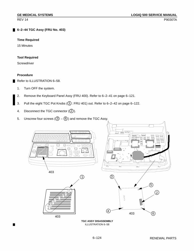
LOGIQ 500 SERVICE MANUALGE MEDICAL SYSTEMS
P9030TA
RENEWAL PARTS6–124
REV 14
6–2–44 TGC Assy (FRU No. 403)
Time Required
15 Minutes
Tool Required
Screwdriver
Procedure
Refer to ILLUSTRATION 6–58.
1. Turn OFF the system.
2. Remove the Keyboard Panel Assy (FRU 400). Refer to 6–2–41 on page 6–121.
3. Pull the eight TGC Pot Knobs ( 1 : FRU 401) out. Refer to 6–2–42 on page 6–122.
4. Disconnect the TGC connector ( 2 ).
5. Unscrew four screws ( 3 – 6 ) and remove the TGC Assy.
ÎÎ Î
ÎÎ
ÎÎ
ÎÎÎÎ
ÎÎÎÎÎ
ÎÎÎÎÎÎÎ
ÎÎÎÎÎÎÎÎÎÎÎÎÎÎÎÎÎÎÎÎÎÎÎÎÎ
ÎÎÎ
ÎÎÎÎÎÎ
ÎÎÎÎÎÎÎ
ÎÎÎÎÎ
ÎÎ
ÎÎ
ÎÎÎÎÎÎ
ÎÎ ÎÎÎÎÎÎÎÎÎÎÎÎÎÎÎÎ
ÎÎÎÎÎÎÎÎÎÎÎÎÎÎÎÎÎÎÎÎÎÎÎÎÎÎÎÎÎÎÎÎÎÎÎÎÎÎÎÎÎÎÎÎÎÎÎÎÎÎÎÎÎÎÎÎÎÎÎÎÎÎÎÎÎÎÎÎÎÎÎÎÎÎÎÎÎÎÎÎÎÎÎÎÎÎÎÎÎÎÎÎÎÎÎÎÎÎÎ
ÎÎÎÎÎÎÎÎÎÎÎÎÎ ÎÎÎÎÎÎÎÎÎÎÎÎÎÎÎÎÎÎÎÎÎÎÎÎÎÎÎÎÎÎÎÎÎÎÎÎÎÎÎÎÎ
ÎÎÎÎÎÎÎÎÎÎÎÎÎÎÎÎÎÎÎÎÎÎÎÎÎÎÎÎÎÎÎÎÎÎÎÎÎÎ
ÎÎÎÎÎÎÎÎÎÎÎÎÎÎÎÎÎÎÎÎÎÎÎÎÎÎÎÎÎÎÎÎÎÎÎÎÎÎÎÎÎÎÎÎÎÎÎÎÎÎÎÎÎÎ
ÎÎ
ÎÎÎÎ
ÎÎÎÎ
ÎÎÎÎÎÎÎ
ÎÎÎ ÎÎÎ
ÎÎÎÎÎÎÎ
ÎÎÎÎÎÎÎÎÎ
ÎÎ
403
ÎÎÎÎÎÎÎÎÎÎÎÎÎÎÎÎÎÎÎÎÎÎÎÎÎÎÎÎÎÎÎÎÎÎÎÎÎÎÎÎÎÎÎÎÎÎÎÎ
ÎÎÎÎÎÎÎÎÎÎ
ÎÎÎÎÎÎÎÎÎÎÎÎ
ÎÎÎÎÎÎÎÎ
ÎÎÎÎÎÎÎÎÎ
ÎÎÎÎÎÎÎÎÎÎÎ
ÎÎÎÎÎÎÎÎÎ
ÎÎÎÎÎÎÎÎÎÎÎÎÎÎÎÎÎÎÎÎÎÎÎÎÎÎÎÎÎÎÎÎ
1
403
ÎÎ
ÎÎ
Î
ÎÎÎÎ
ÎÎ
2
3
4
5
6403
Î ÎÎÎÎÎÎÎÎ
ÎÎÎÎ
ÎÎÎÎ Î
Î
ÎÎÎÎÎ
ÎÎÎÎÎÎÎÎÎÎÎÎÎÎÎÎÎÎÎÎÎÎÎÎÎÎ
TGC ASSY DISASSEMBLYILLUSTRATION 6–58

LOGIQ 500 SERVICE MANUALGE MEDICAL SYSTEMS
P9030TA
RENEWAL PARTS6–125
REV 14
6–2–45 I/F Board Assy (FRU No. 405)
Time Required
25 Minutes
Tool Required
ScrewdriverHexagonal Socket Wrench
Procedure
Refer to ILLUSTRATION 6–59.
1. Turn OFF the system.
2. Remove the Keyboard Panel Assy. Refer to 6–2–41 on page 6–121.
3. Remove the VFD Assy. Refer to 6–2–49 on page 6–131.
4. Unscrew six screws ( 1 – 6 ) and remove the Holding Metal.
5. Disconnect the three connectors ( 7 – 9 ).
6. Remove one Stud (10 ).
7. Unscrew seven screws ( 11 – 17 ) and remove the I/F Board Assy.
I/F BOARD ASSY DISASSEMBLYILLUSTRATION 6–59

LOGIQ 500 SERVICE MANUALGE MEDICAL SYSTEMS
P9030TA
RENEWAL PARTS6–126
REV 14
6–2–46 A/N Keyboard Assy (FRU No. 406)
Time Required
30 Minutes
Tool Required
ScrewdriverHexagonal Socket Wrench
Procedure
Refer to ILLUSTRATION 6–60.
1. Turn OFF the system.
2. Remove the Keyboard Panel Assy. Refer to 6–2–41 on page 6–121.
3. Remove the VFD Assy. Refer to 6–2–49 on page 6–131.
4. Remove the I/F Board Assy. Refer to 6–2–45 on page 6–125.
5. Unscrew five screws ( 1 – 5 ).
6. Disconnect the A/N keyboard connectors ( 6 ).
7. Remove the A/N Keyboard Assy.
A/N KEYBOARD ASSY DISASSEMBLYILLUSTRATION 6–60

LOGIQ 500 SERVICE MANUALGE MEDICAL SYSTEMS
P9030TA
RENEWAL PARTS6–127
REV 14
This page is left blank intentionally.
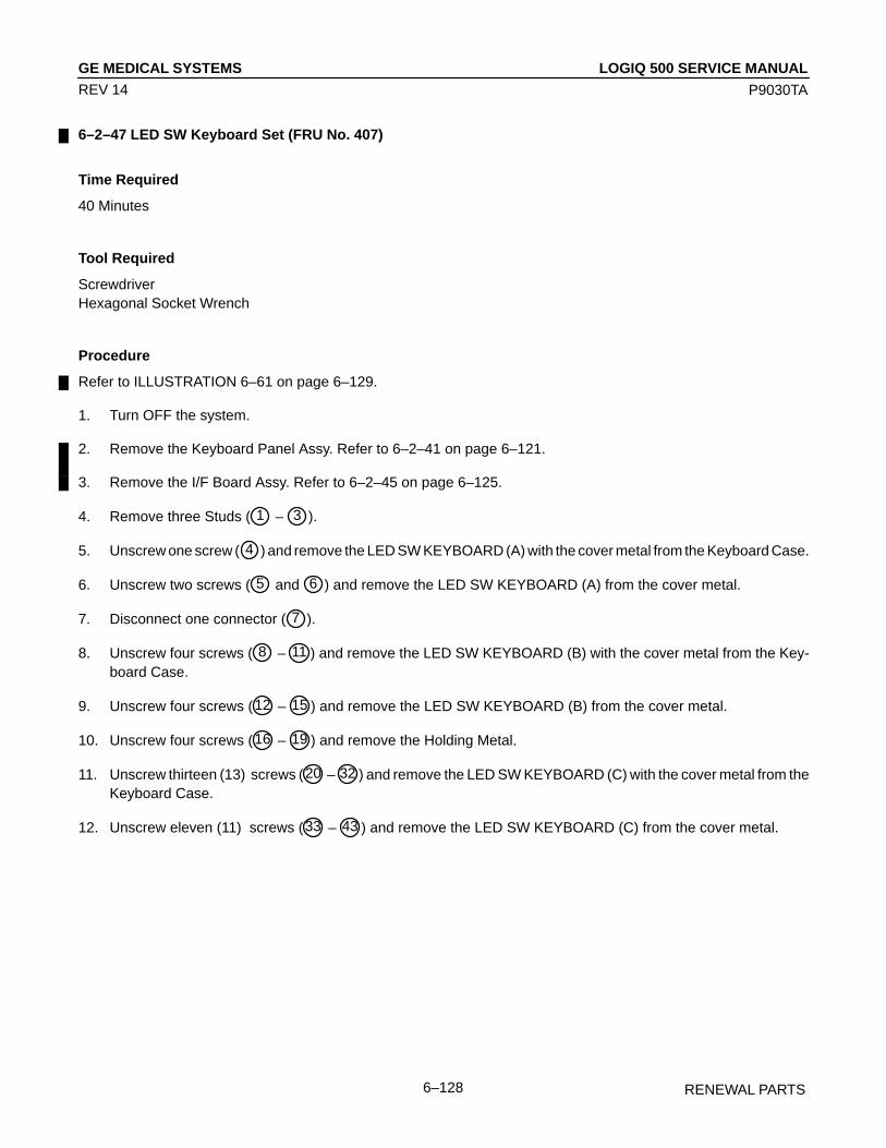
LOGIQ 500 SERVICE MANUALGE MEDICAL SYSTEMS
P9030TA
RENEWAL PARTS6–128
REV 14
6–2–47 LED SW Keyboard Set (FRU No. 407)
Time Required
40 Minutes
Tool Required
ScrewdriverHexagonal Socket Wrench
Procedure
Refer to ILLUSTRATION 6–61 on page 6–129.
1. Turn OFF the system.
2. Remove the Keyboard Panel Assy. Refer to 6–2–41 on page 6–121.
3. Remove the I/F Board Assy. Refer to 6–2–45 on page 6–125.
4. Remove three Studs ( 1 – 3 ).
5. Unscrew one screw ( 4 ) and remove the LED SW KEYBOARD (A) with the cover metal from the Keyboard Case.
6. Unscrew two screws ( 5 and 6 ) and remove the LED SW KEYBOARD (A) from the cover metal.
7. Disconnect one connector ( 7 ).
8. Unscrew four screws ( 8 – 11 ) and remove the LED SW KEYBOARD (B) with the cover metal from the Key-board Case.
9. Unscrew four screws (12 – 15 ) and remove the LED SW KEYBOARD (B) from the cover metal.
10. Unscrew four screws (16 – 19 ) and remove the Holding Metal.
11. Unscrew thirteen (13) screws (20 – 32 ) and remove the LED SW KEYBOARD (C) with the cover metal from theKeyboard Case.
12. Unscrew eleven (11) screws (33 – 43 ) and remove the LED SW KEYBOARD (C) from the cover metal.

LOGIQ 500 SERVICE MANUALGE MEDICAL SYSTEMS
P9030TA
RENEWAL PARTS6–129
REV 14
6–2–47 LED SW Keyboard Set (FRU No. 407) (continued)
LED SW KEYBOARD SET DISASSEMBLYILLUSTRATION 6–61

LOGIQ 500 SERVICE MANUALGE MEDICAL SYSTEMS
P9030TA
RENEWAL PARTS6–130
REV 14
6–2–48 Gain Encoder (FRU No. 408)
Time Required
15 Minutes
Tool Required
Screwdriver
Procedure
Refer to ILLUSTRATION 6–62.
1. Turn OFF the system.
2. Remove the Keyboard Panel Assy. Refer to 6–2–41 on page 6–121.
3. Unscrew four screws ( 1 – 4 ).
4. Disconnect the gain encoder connector ( 5 ).
GAIN ENCODER DISASSEMBLYILLUSTRATION 6–62
NoteThe appearance of new Gain Encoder (2206005) is different from the old one (2164871).
NoteThe new Gain Encoder (2206005) can be used only for the console with the software version 3.30 orlater.
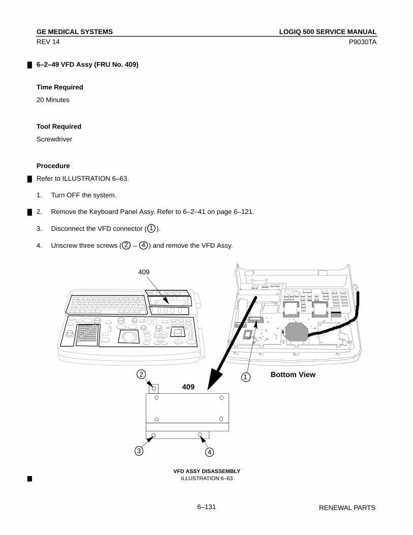
LOGIQ 500 SERVICE MANUALGE MEDICAL SYSTEMS
P9030TA
RENEWAL PARTS6–131
REV 14
6–2–49 VFD Assy (FRU No. 409)
Time Required
20 Minutes
Tool Required
Screwdriver
Procedure
Refer to ILLUSTRATION 6–63.
1. Turn OFF the system.
2. Remove the Keyboard Panel Assy. Refer to 6–2–41 on page 6–121.
3. Disconnect the VFD connector ( 1 ).
4. Unscrew three screws ( 2 – 4 ) and remove the VFD Assy.
Î ÎÎÎÎÎÎÎÎ
ÎÎÎÎÎÎÎÎ
ÎÎÎÎÎÎÎ
ÎÎÎÎ
ÎÎÎÎÎÎÎÎÎÎÎÎÎÎÎÎÎÎÎÎÎÎÎÎÎÎ Î
Î ÎÎ
ÎÎÎ
ÎÎÎÎ ÎÎÎÎÎÎÎÎÎÎÎ
ÎÎÎÎÎÎÎÎÎÎÎÎÎÎÎÎÎÎÎÎ
ÎÎÎ
ÎÎÎÎ
ÎÎÎÎÎÎ ÎÎÎ
ÎÎ
ÎÎ Î
ÎÎÎÎÎ
ÎÎÎ ÎÎÎÎÎÎÎÎÎÎÎÎÎÎ
ÎÎÎÎÎÎÎÎÎÎÎÎÎÎÎÎÎÎÎÎÎÎÎÎÎÎÎÎÎÎÎÎÎÎÎÎÎÎÎÎÎÎÎÎÎÎÎÎÎÎÎÎÎÎÎÎÎÎÎÎÎÎÎÎÎÎÎÎÎÎÎÎÎÎÎÎÎÎÎÎÎÎÎÎÎÎÎÎÎÎÎÎÎÎÎÎÎÎÎÎÎÎÎÎÎÎ
ÎÎÎÎÎÎÎÎÎÎÎÎÎÎÎÎÎ ÎÎÎÎÎÎÎÎÎÎÎÎÎÎÎÎÎÎÎÎÎ
ÎÎÎÎÎÎÎÎÎÎÎÎÎÎÎÎÎÎÎÎÎÎÎÎÎÎÎÎÎÎÎÎÎÎÎÎÎÎÎÎÎÎÎÎÎ
ÎÎÎÎÎÎÎÎÎÎÎÎÎÎÎÎÎÎÎÎÎÎÎÎÎÎÎÎÎÎÎÎÎÎÎÎÎÎÎÎÎÎÎÎÎÎÎÎÎÎÎÎÎÎÎÎÎÎÎÎÎÎÎÎÎÎÎÎÎÎÎÎÎÎÎÎÎÎÎ
ÎÎ
Î
ÎÎÎÎ
ÎÎÎÎÎÎÎÎÎÎÎÎ
ÎÎÎÎÎÎ
ÎÎÎÎÎÎ
ÎÎÎ
ÎÎ
ÎÎ
409
ÎÎÎÎÎÎÎÎÎÎÎÎÎÎÎÎÎÎÎÎÎÎÎÎÎÎÎÎÎÎÎÎÎÎÎÎÎÎÎÎÎÎÎÎÎÎÎÎÎÎÎÎÎÎÎÎÎÎÎÎÎÎÎÎÎÎÎÎ
ÎÎÎÎÎÎ
ÎÎ
Î
ÎÎÎ
ÎÎ
2
3 4
409
Bottom View1
VFD ASSY DISASSEMBLYILLUSTRATION 6–63
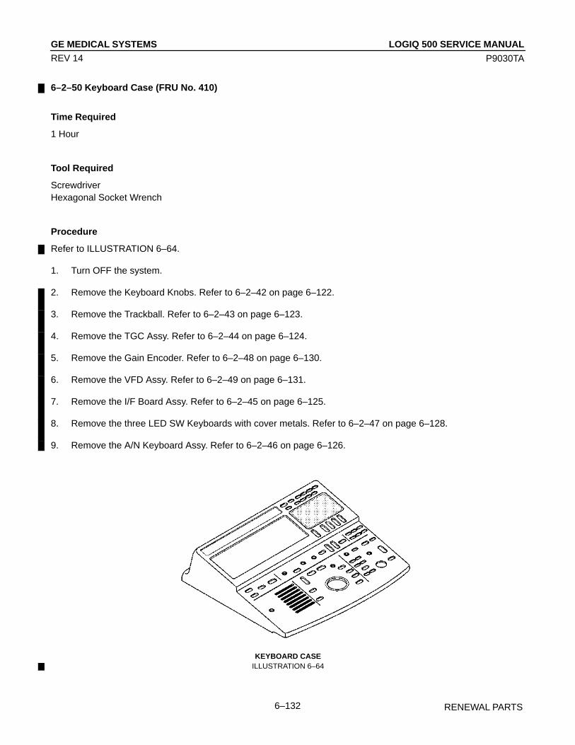
LOGIQ 500 SERVICE MANUALGE MEDICAL SYSTEMS
P9030TA
RENEWAL PARTS6–132
REV 14
6–2–50 Keyboard Case (FRU No. 410)
Time Required
1 Hour
Tool Required
ScrewdriverHexagonal Socket Wrench
Procedure
Refer to ILLUSTRATION 6–64.
1. Turn OFF the system.
2. Remove the Keyboard Knobs. Refer to 6–2–42 on page 6–122.
3. Remove the Trackball. Refer to 6–2–43 on page 6–123.
4. Remove the TGC Assy. Refer to 6–2–44 on page 6–124.
5. Remove the Gain Encoder. Refer to 6–2–48 on page 6–130.
6. Remove the VFD Assy. Refer to 6–2–49 on page 6–131.
7. Remove the I/F Board Assy. Refer to 6–2–45 on page 6–125.
8. Remove the three LED SW Keyboards with cover metals. Refer to 6–2–47 on page 6–128.
9. Remove the A/N Keyboard Assy. Refer to 6–2–46 on page 6–126.
KEYBOARD CASEILLUSTRATION 6–64

LOGIQ 500 SERVICE MANUALGE MEDICAL SYSTEMS
P9030TA
RENEWAL PARTS6–133
REV 14
6–2–51 A/N Key–top Set (FRU No. 411)
Time Required
5 Minutes
Tool Required
Tweezers
Procedure
Refer to ILLUSTRATION 6–65.
1. Turn OFF the system.
2. Insert the tweezers into the bottom of key–top.
3. Remove the key–top as shown in ILLUSTRATION 6–65.
4. Insert the A/N Key–top Set according to the language. Refer to ILLUSTRATION 6–66 on page 6–134.
A/N KEY–TOP DISASSEMBLYILLUSTRATION 6–65

LOGIQ 500 SERVICE MANUALGE MEDICAL SYSTEMS
P9030TA
RENEWAL PARTS6–134
REV 14
6–2–51 A/N Key–top Set (FRU No. 411) (continued)
Key–top for English, French, German, Spanish, Italian, Portuguese, Swedish and Danish
Key–top for GreekILLUSTRATION 6–66
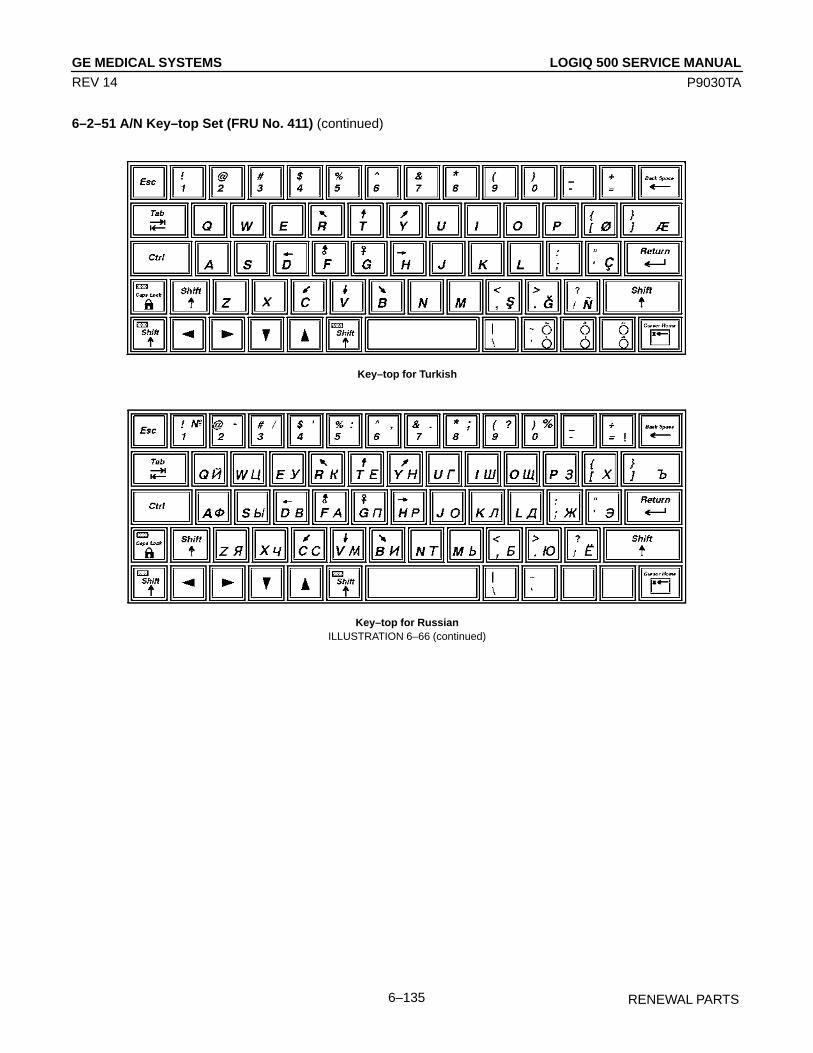
LOGIQ 500 SERVICE MANUALGE MEDICAL SYSTEMS
P9030TA
RENEWAL PARTS6–135
REV 14
6–2–51 A/N Key–top Set (FRU No. 411) (continued)
Key–top for Turkish
Key–top for RussianILLUSTRATION 6–66 (continued)

LOGIQ 500 SERVICE MANUALGE MEDICAL SYSTEMS
P9030TA
RENEWAL PARTS6–136
REV 14
6–2–52 LED SW Key–top Set (FRU No. 412)
Time Required
40 Minutes
Tool Required
ScrewdriverHexagonal Socket Wrench
Procedure
Refer to ILLUSTRATION 6–67.
1. Turn OFF the system.
2. Remove the Keyboard Panel Assy. Refer to 6–2–41 on page 6–121.
3. Remove the LED SW Keyboards. Refer to 6–2–47 on page 6–128.
4. Remove the key–tops for rocker switch as shown in ILLUSTRATION 6–67.
LED SW KEY–TOP DISASSEMBLYILLUSTRATION 6–67
NoteYou can remove the key–tops for push switch by removing the holding metals from the LED SW Key-boards.

LOGIQ 500 SERVICE MANUALGE MEDICAL SYSTEMS
P9030TA
RENEWAL PARTS6–137
REV 14
This page is left blank intentionally.

LOGIQ 500 SERVICE MANUALGE MEDICAL SYSTEMS
P9030TA
RENEWAL PARTS6–138
REV 14
6–2–53 Rear CONN Panel Assy (FRU No. 501) and Rear CONN Panel2 Assy (FRU No. 501B)
Time Required
0.5 Hour
Tool Required
Screwdriver
Procedure
Refer to ILLUSTRATION 6–68 and ILLUSTRATION 6–69.
1. Turn OFF the system.
2. Remove the Front Base Cover (FRU 307). Refer to 6–2–26 on page 6–103.
3. Remove the Side Cover Right (FRU 302). Refer to 6–2–21 on page 6–98.
NoteThe Linear Slide Cover is installed from the production unit of LOGIQ 500 console with software Ver-sion 5.00y or later. Refer to ILLUSTRATION 6–30 on page 6–93. Remove the Linear Slide Cover.
NoteUnscrew the two screws ( 1 and 2 ) to remove the Rear CONN Spacer. Refer toILLUSTRATION 6–68. The Rear CONN Spacer is installed from the production unit of LOGIQ 500console with software Version 5.00y or later.
REAR CONN SPACER DISASSEMBLYILLUSTRATION 6–68

LOGIQ 500 SERVICE MANUALGE MEDICAL SYSTEMS
P9030TA
RENEWAL PARTS6–139
REV 14
6–2–53 Rear CONN Panel Assy (FRU No. 501) and Rear CONN Panel2 Assy (FRU No. 501B) (continued)
4. Remove the Rear Cover Assy (FRU 303). Refer to 6–2–22 on page 6–99.
5. Unscrew four screws ( 1 – 4 ) and pull the Rear CONN Panel Assy or the Rear CONN Panel2 Assy out.
6. Disconnect three connectors ( 5 ) out of the Rear 1 Assy or one connector out of the Rear3 Assy.
7. Disconnect one connector ( 6 ) out of the Rear 2 Assy.
8. Disconnect two connectors. One of them is connected with the Power Supply Unit ( 7 ), and another is connectedwith the B/W Printer Panel ( 8 ).
9. Unscrew three screws to remove the frame ground fixed on the frame at the right side of the console.
10. Remove the Rear CONN Panel Assy (or the Rear CONN Panel2 Assy).
1
2
3
4
ÎÎÎÎÎÎÎÎÎ
ÎÎÎÎÎÎÎÎÎÎÎÎÎÎÎÎÎÎÎÎÎÎÎÎÎÎ
ÎÎÎÎÎÎÎÎÎÎÎÎ
ÎÎÎÎÎÎÎÎ
ÎÎ
ÎÎ ÎÎÎ
ÎÎÎÎÎÎÎÎÎÎÎÎÎÎÎÎ
ÎÎÎÎÎÎÎÎÎÎÎ
ÎÎÎÎÎÎÎÎÎ
ÎÎÎÎÎÎ
ÎÎÎÎÎÎÎÎÎÎÎÎÎÎÎÎÎÎÎÎÎÎÎÎÎÎÎÎÎÎÎÎÎÎ
ÎÎÎÎÎÎÎÎÎÎÎÎÎ
ÎÎ
ÎÎ
ÎÎ
Î
ÎÎÎ
ÎÎÎÎÎÎÎÎÎÎÎÎÎÎÎÎÎÎÎÎÎÎÎÎÎÎÎÎÎÎÎÎÎÎÎÎÎÎÎÎÎÎÎÎÎÎÎÎ
ÎÎÎÎÎÎÎÎÎÎÎÎÎÎÎÎÎÎÎÎ
ÎÎÎÎÎÎÎ
ÎÎÎÎÎÎÎÎ
ÎÎÎÎÎÎÎÎÎÎÎÎÎÎÎ
ÎÎÎÎÎÎÎÎ
ÎÎÎ
Front side ofRear Panel Assy
P101
ÎÎÎÎÎÎÎÎ Rear 1 Assy
Rear 2 Assy
5
6
ÎÎÎ
Î
ÎÎÎÎÎÎ
ÎÎÎ
ÎÎ
ÎÎÎÎÎÎÎÎ
Î
ÎÎ
Î
Î
ÎÎ
ÎÎ
ÎÎ
Î
Î
ÎÎÎ
ÎÎÎÎ
ÎÎ
ÎÎÎÎÎÎÎÎ
ÎÎÎÎÎÎ
ÎÎÎÎÎÎ
ÎÎÎÎÎÎÎÎ
ÎÎÎÎÎÎÎÎ
ÎÎÎÎÎÎÎÎÎÎÎÎÎÎÎÎÎÎÎÎÎÎÎÎÎÎÎÎÎ
ÎÎÎÎ
Î
ÎÎÎÎ
ÎÎ
7connector
Back side of Rear Panel Assy
P102 8 connector
REAR CONN PANEL ASSY DISASSEMBLYILLUSTRATION 6–69

LOGIQ 500 SERVICE MANUALGE MEDICAL SYSTEMS
P9030TA
RENEWAL PARTS6–140
REV 14
6–2–54 Rear 1 Assy (FRU No. 502)
Time Required
1 Hour
Tool Required
Screwdriver
Procedure
Refer to ILLUSTRATION 6–70 on page 6–141.
1. Turn OFF the system.
2. Remove the Rear CONN Panel Assy (FRU 501). Refer to 6–2–53 on page 6–138.
3. Disconnect three connectors ( 5 – 7 ) out of the Rear 1 Assy.
4. Disconnect twenty connectors in the gray shaded area ( 9 ).
5. Remove the SCSI Terminator (FRU 505). Refer to 6–2–58 on page 6–146.
NoteThe SCSI Terminator is not installed in the console with the 3.5–inch HDD.
6. Unscrew two screws ( 8 ) out of the SCSI BUS Connector located on the front of the Rear Panel Assy.
7. Unscrew four screws ( 1 – 4 ).
8. Remove the Rear 1 Assy.
NoteThe Rear1 Assy is not included in the Rear CONN Panel2 Assy.

LOGIQ 500 SERVICE MANUALGE MEDICAL SYSTEMS
P9030TA
RENEWAL PARTS6–141
REV 14
6–2–54 Rear 1 Assy (FRU No. 502) (continued)
ÎÎÎÎÎÎÎÎÎÎ
Rear 1 Assy
ÎÎÎÎÎÎÎÎÎÎÎÎÎÎÎÎÎÎÎÎ
ÎÎÎÎÎÎÎÎÎ
ÎÎ
ÎÎÎÎ
ÎÎÎÎÎÎÎÎÎÎÎÎÎÎÎÎÎ
ÎÎÎÎÎÎÎ
ÎÎÎÎÎÎÎÎÎÎÎ
ÎÎÎÎÎÎÎÎÎÎÎÎÎÎÎÎÎÎÎÎÎÎÎÎÎÎÎÎÎÎÎÎÎÎÎÎÎÎÎÎÎÎÎÎÎÎÎÎÎÎ
Î
ÎÎÎÎ
ÎÎÎÎÎÎÎÎÎÎ
ÎÎÎ
Î
ÎÎÎÎÎÎÎÎÎÎ
ÎÎÎ
ÎÎ
Î ÎÎ
ÎÎÎÎ
ÎÎÎÎÎ
Î
ÎÎÎÎ
ÎÎÎ
ÎÎÎ ÎÎÎÎ
ÎÎÎÎÎÎ
ÎÎ
ÎÎÎÎÎÎÎ
ÎÎ
ÎÎÎÎ
Î
ÎÎÎÎÎÎ
ÎÎÎÎÎÎÎÎÎ
Î
ÎÎÎÎÎÎÎÎÎÎÎÎÎÎÎÎÎÎÎÎ
ÎÎ
ÎÎÎ
Î
Î
ÎÎ
ÎÎÎÎÎÎÎÎÎÎÎÎÎÎÎÎ
ÎÎÎÎÎÎÎÎÎÎÎÎÎÎÎÎÎÎ
ÎÎÎÎÎ
ÎÎÎÎÎÎÎÎÎÎÎÎÎ
ÎÎÎÎÎÎÎÎÎÎÎÎÎ
ÎÎÎÎÎÎÎÎÎÎÎÎÎÎÎÎÎÎ
ÎÎÎÎÎÎÎÎÎÎÎÎÎ
ÎÎ
Front of Rear Panel Assy
1 2
3
ÎÎÎÎÎÎ
Î
ÎÎÎÎ
Î
ÎÎÎÎÎÎÎÎÎ
ÎÎÎÎÎ
ÎÎÎÎÎ
ÎÎ
ÎÎ
ÎÎ
ÎÎ
Î
ÎÎ
Î
Î
Î
Î
Î
ÎÎ
ÎÎ
ÎÎ
ÎÎÎÎÎÎÎÎÎÎÎ
ÎÎÎÎÎÎÎÎ
ÎÎÎÎÎÎÎÎ
ÎÎÎÎÎÎÎÎÎÎÎÎÎÎÎ
ÎÎÎÎÎÎÎÎÎÎÎÎÎ
ÎÎÎÎÎÎ
ÎÎÎÎÎÎÎÎÎÎÎÎÎÎÎÎÎÎÎÎÎÎÎÎÎÎÎ
ÎÎÎÎÎÎÎÎÎÎÎÎÎÎÎÎÎÎÎÎÎÎ
ÎÎÎÎÎÎÎÎ
ÎÎ
ÎÎÎÎ
ÎÎÎÎÎÎ
Back of Rear Panel Assy
4
5
6
7
9
8
REAR 1 ASSY DISASSEMBLYILLUSTRATION 6–70

LOGIQ 500 SERVICE MANUALGE MEDICAL SYSTEMS
P9030TA
RENEWAL PARTS6–142
REV 14
6–2–55 Rear 2 Assy (FRU No. 503)
Time Required
1 Hours
Tool Required
ScrewdriverHexagonal Wrench
Procedure
Refer to ILLUSTRATION 6–71 on page 6–143.
1. Turn OFF the system.
2. Remove the Rear CONN Panel Assy (FRU 501) or the Rear CONN Panel2 Assy (FRU 501B). Refer to 6–2–53 onpage 6–138.
3. Unscrew four screws ( 1 – 4 ) to remove the rear plate.
4. Unscrew ten hexagonal bolts ( 5 – 14 ).
5. Remove the Rear 2 Assy.

LOGIQ 500 SERVICE MANUALGE MEDICAL SYSTEMS
P9030TA
RENEWAL PARTS6–143
REV 14
6–2–55 Rear 2 Assy (FRU No. 503) (continued)
Rear CONN Panel Assy(Rear Side View)
ÎÎ
ÎÎ
ÎÎÎÎ
Î
ÎÎ
ÎÎÎÎÎÎÎÎÎÎÎÎÎÎÎÎÎÎÎÎÎÎÎ
ÎÎÎÎÎÎÎÎÎÎÎÎÎÎÎÎÎÎ
ÎÎÎÎÎÎ
ÎÎÎÎÎÎÎÎÎÎ
ÎÎÎÎÎÎÎ
ÎÎÎÎÎÎ
ÎÎÎÎÎÎÎÎÎÎ
ÎÎÎÎÎÎÎÎÎÎÎÎÎÎÎÎ
Î
ÎÎ
ÎÎÎÎ
ÎÎÎÎ
ÎÎ
ÎÎÎÎ
ÎÎÎÎÎÎÎ
ÎÎÎ
ÎÎÎÎÎÎÎ
ÎÎ
Î
Î
Î
Î
ÎÎÎ
Î
Î
Î
Î
Î
ÎÎ
ÎÎ
Î
ÎÎÎÎÎÎÎÎÎÎÎÎÎ
ÎÎÎÎÎÎÎÎ
ÎÎÎÎÎÎÎÎ
ÎÎÎÎÎÎÎÎÎÎ
ÎÎÎÎÎÎÎÎÎÎÎ
ÎÎÎÎÎÎ
ÎÎÎÎÎÎÎÎÎÎÎÎÎÎ
ÎÎÎÎÎÎ
ÎÎÎÎÎÎÎÎÎÎÎÎÎÎÎÎÎÎÎ
ÎÎÎÎÎÎ
ÎÎ
ÎÎÎÎ
ÎÎÎ
Rear CONN Panel Assy(Front Side View)
1
13
14
2
6
7
8
9
1011
12
ÎÎÎÎÎÎÎÎÎÎÎÎÎÎÎÎÎÎÎÎÎÎÎÎÎÎÎÎÎÎ
Rear 2 Assy
Rear 2 Assy is behind Rear 1 Assy
3 4
5
REAR 2 ASSY DISASSEMBLYILLUSTRATION 6–71
NoteThe back view of the Rear CONN Panel2 Assy is different from the Rear CONN Panel Assy.

LOGIQ 500 SERVICE MANUALGE MEDICAL SYSTEMS
P9030TA
RENEWAL PARTS6–144
REV 14
6–2–56 Rear 3 Assy (FRU No. 590)
Time Required
1 Hours
Tool Required
Screwdriver
Procedure
Refer to ILLUSTRATION 6–72.
1. Turn OFF the system.
2. Remove the Rear CONN Panel2 Assy (FRU 501B). Refer to 6–2–53 on page 6–138.
3. Disconnect one connector ( 1 ) from the Rear3 Assy as shown in ILLUSTRATION 6–72.
4. Unscrew thirteen screws ( 2 – 14 ). Refer to ILLUSTRATION 6–72.
5. Remove the Rear 3 Assy.
REAR 3 ASSY DISASSEMBLYILLUSTRATION 6–72

LOGIQ 500 SERVICE MANUALGE MEDICAL SYSTEMS
P9030TA
RENEWAL PARTS6–145
REV 14
6–2–57 Rear Connector Set (FRU No. 504)
Time Required
10 Minutes
Tool Required
ScrewdriverHexagonal Wrench
Procedure
Refer to ILLUSTRATION 6–73.
1. Turn OFF the system.
2. Remove the Rear CONN Panel Assy (FRU 501). Refer to 6–2–53 on page 6–138.
3. Unscrew four screws ( 1 – 4 ) to remove the rear plate.
4. Unscrew the hexagonal bolts ( 5 and 6 ) from the back side of the Rear CONN Assy to remove five BNC pinsand two Audio pins.
5. Unscrew two screws ( 7 ) to remove the Y/C Jack.
6. Disconnect the connectors from the Rear 1 Assy.
Rear CONN Panel Assy(Front Side View)
Hexagonal Bolts are at theback side of the Rear Plate.
ÎÎÎÎÎÎ
ÎÎ
ÎÎÎÎÎÎ
ÎÎÎÎÎ
ÎÎÎ
ÎÎÎÎÎÎÎÎ
ÎÎ
Î
ÎÎ
Î
Î
ÎÎÎ
ÎÎÎÎ
Î
ÎÎÎÎ
ÎÎ
ÎÎÎ
Î
ÎÎ
ÎÎÎÎÎÎ
ÎÎÎÎÎÎ
ÎÎÎÎÎÎ
ÎÎÎÎÎÎÎÎ
ÎÎÎÎÎÎÎÎ
ÎÎÎÎ
ÎÎÎÎÎÎÎÎÎÎÎÎÎÎÎÎÎÎÎÎÎÎÎÎÎÎÎÎÎÎ
ÎÎÎÎ
Î
ÎÎÎÎ
ÎÎ
1 2
4
Rear CONN Panel Assy(Rear Side View)
3
REAR CONNECTORS DISASSEMBLYILLUSTRATION 6–73
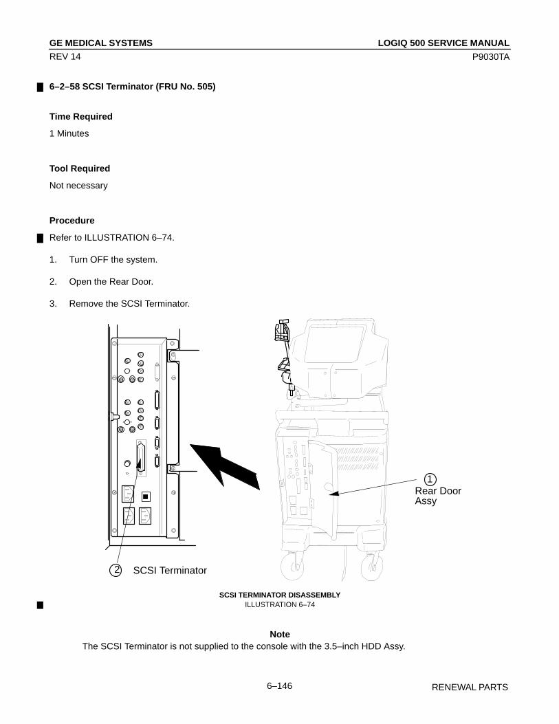
LOGIQ 500 SERVICE MANUALGE MEDICAL SYSTEMS
P9030TA
RENEWAL PARTS6–146
REV 14
6–2–58 SCSI Terminator (FRU No. 505)
Time Required
1 Minutes
Tool Required
Not necessary
Procedure
Refer to ILLUSTRATION 6–74.
1. Turn OFF the system.
2. Open the Rear Door.
3. Remove the SCSI Terminator.
SCSI Terminator
ÎÎÎÎÎÎÎÎÎ
ÎÎÎÎ
ÎÎÎ ÎÎÎÎÎÎÎÎÎÎÎ
ÎÎÎÎÎÎÎÎÎÎÎÎ
ÎÎÎ
ÎÎ Î
ÎÎ
ÎÎÎÎÎÎÎ
ÎÎÎÎÎÎÎ ÎÎÎ
Î
ÎÎÎÎ
ÎÎ ÎÎ
Î
ÎÎÎÎÎÎÎÎÎÎÎÎÎÎÎÎÎÎÎÎÎÎÎÎÎÎ
ÎÎÎ
ÎÎ
ÎÎÎ
ÎÎÎÎÎÎÎÎÎÎÎÎÎÎÎÎÎÎÎÎÎÎÎÎÎÎÎÎÎÎÎÎÎÎÎÎÎÎÎÎÎÎÎÎÎÎÎÎÎÎÎÎÎÎÎÎÎÎÎÎÎÎÎÎÎÎÎÎÎÎÎÎÎÎÎÎÎÎÎÎÎÎÎÎÎÎÎÎÎÎ
ÎÎÎ
ÎÎÎÎÎÎÎÎÎÎÎÎÎÎÎÎÎÎÎÎÎ
ÎÎÎÎÎÎÎÎÎÎÎÎÎÎÎÎÎÎÎÎÎÎÎÎÎÎÎÎÎÎÎÎ
ÎÎ
ÎÎ
ÎÎÎÎÎÎÎÎÎÎÎÎ
ÎÎÎÎÎÎÎÎÎÎÎÎÎÎÎÎÎÎÎ
ÎÎÎ
ÎÎÎ
ÎÎÎÎÎÎÎÎÎÎÎÎÎÎÎÎÎÎÎÎÎÎÎÎÎÎÎÎÎÎÎÎÎÎÎÎÎÎÎÎÎÎÎÎÎÎÎÎÎÎÎÎÎÎÎÎ
Î
Î
Î
Î
Î
ÎÎ
Î
ÎÎ
ÎÎ
ÎÎ
ÎÎÎÎÎÎÎÎÎÎÎÎÎÎÎÎÎÎÎÎÎÎÎÎÎÎÎÎÎÎÎÎÎÎÎÎÎÎÎÎÎÎÎÎ
ÎÎÎÎÎÎÎÎÎÎÎÎÎÎÎÎÎÎÎÎÎÎÎÎÎÎÎÎÎÎÎÎ
ÎÎÎÎÎÎÎÎÎ
ÎÎÎÎÎÎÎÎÎÎÎÎÎÎÎÎÎÎ
ÎÎÎÎÎÎÎ
ÎÎÎÎÎÎÎ
ÎÎÎÎÎÎÎÎ
ÎÎÎÎÎÎÎÎÎÎÎÎÎÎÎÎÎÎÎÎÎÎÎÎÎÎÎÎ
ÎÎ
ÎRear DoorAssy
1
2
SCSI TERMINATOR DISASSEMBLYILLUSTRATION 6–74
NoteThe SCSI Terminator is not supplied to the console with the 3.5–inch HDD Assy.

LOGIQ 500 SERVICE MANUALGE MEDICAL SYSTEMS
P9030TA
RENEWAL PARTS6–147
REV 14
6–2–59 Circuit Protector (FRU No. 506: 7A, FRU No. 507: 3A)
Time Required
30 Minutes
Tool Required
ScrewdriverSoldering Iron
Procedure
Refer to ILLUSTRATION 6–75.
1. Turn OFF the system.
2. Remove the Rear CONN Panel Assy (FRU 501) or the Rear CONN Panel2 Assy (FRU 501B). Refer to 6–2–53 onpage 6–138.
3. Remove the soldered cord ( 1 ).
4. Remove the Circuit Protector toward the direction indicated by the 2 arrow.
ÏÏÏÏÏÏÏÏÏ
ÎÎÎÎ
ÎÎÎÎÎÎÎ
ÎÎÎÎÎÎÎ
ÎÎÎ
ÎÎÎÎÎÎÎÎÎ
ÎÎ
Î
ÎÎ
Î
ÎÎ
ÎÎ
Î
Î
Î
ÎÎ
Î
ÎÎ
ÎÎ
ÎÎ
ÎÎÎÎÎÎ
ÎÎÎÎÎÎÎÎÎÎÎÎ
ÎÎÎÎÎÎ
ÎÎÎÎÎÎÎÎ
ÎÎÎÎÎÎÎÎÎÎÎÎÎÎ
ÎÎÎÎÎÎÎÎÎÎÎÎÎÎÎÎÎÎÎÎÎÎÎÎ
ÎÎÎÎÎÎÎÎÎÎÎÎÎÎÎÎÎÎÎ
ÎÎÎÎ
Î
ÎÎÎÎ
ÎÎÎÎ
Rear CONN Panel Assy(Rear Side View)
ÎÎÎÎ
1ÎÎÎÎÎÎÎÎÎÎÎÎÎÎÎÎ
ÎÎÎÎ
ÎÎÎÎÎÎ
RearPanel
ÎÎÎÎÎÎÎÎÎÎÎÎÎÎ
ÎÎÎÎ
ÎÎÎÎ
ÎÎÎÎ
i) detail of connector ii) different angle of 90 deg
ÎÎÎÎ2
ÎÎÎÎÎÎÎ
ÎÎÎÎÎÎ
Push Push
CIRCUIT PROTECTOR DISASSEMBLYILLUSTRATION 6–75

LOGIQ 500 SERVICE MANUALGE MEDICAL SYSTEMS
P9030TA
RENEWAL PARTS6–148
REV 14
6–2–60 HV Assy (FRU No. 508)
Time Required
10 Minutes
Tool Required
Screwdriver
Procedure
Refer to ILLUSTRATION 6–76.
1. Turn OFF the system.
2. Remove the Rear Cover Assy (FRU 303). Refer to 6–2–22 on page 6–99.
3. Disconnect three connectors ( 1 – 3 ).
4. Remove two screws ( 5 and 7 ) and loosen two screws ( 4 and 6 ).
5. Remove the HV Assy.
HV Assy
1
2
3
4
5
6
7
HV ASSY DISASSEMBLYILLUSTRATION 6–76

LOGIQ 500 SERVICE MANUALGE MEDICAL SYSTEMS
P9030TA
RENEWAL PARTS6–149
REV 14
6–2–61 HV Fan Set (FRU No. 509)
Time Required
15 Minutes
Tool Required
Screwdriver
Procedure
Refer to ILLUSTRATION 6–77.
1. Turn OFF the system.
2. Remove the Rear Cover Assy (FRU 303). Refer to 6–2–22 on page 6–99.
3. Remove the HV Assy (FRU 508). Refer to 6–2–60 on page 6–148.
4. Unscrew six screws ( 1 – 6 ) to disassemble the HV Assy.
5. Disconnect two connectors ( 7 and 8 ).
6. Unscrew four screws ( 9 – 12 ).
HV FAN SET DISASSEMBLYILLUSTRATION 6–77
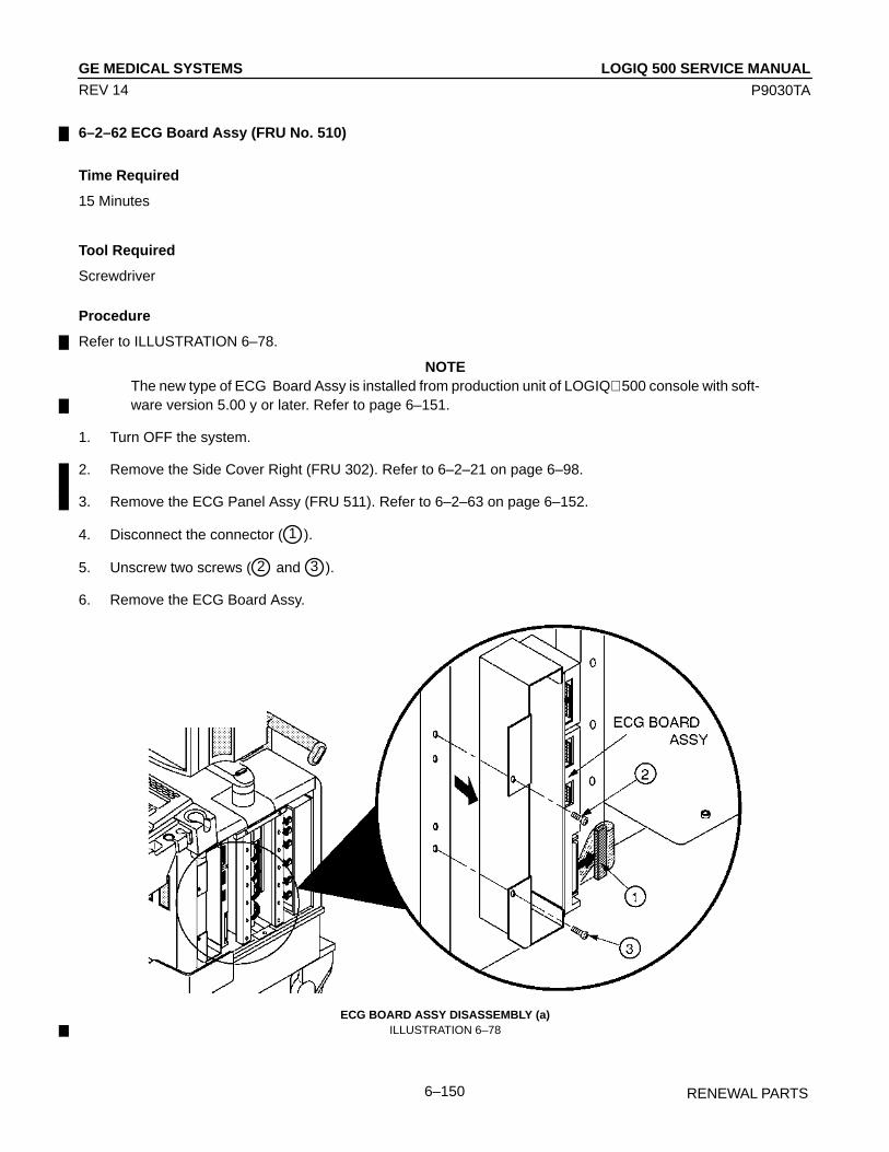
LOGIQ 500 SERVICE MANUALGE MEDICAL SYSTEMS
P9030TA
RENEWAL PARTS6–150
REV 14
6–2–62 ECG Board Assy (FRU No. 510)
Time Required
15 Minutes
Tool Required
Screwdriver
Procedure
Refer to ILLUSTRATION 6–78.
NOTEThe new type of ECG Board Assy is installed from production unit of LOGIQ 500 console with soft-ware version 5.00 y or later. Refer to page 6–151.
1. Turn OFF the system.
2. Remove the Side Cover Right (FRU 302). Refer to 6–2–21 on page 6–98.
3. Remove the ECG Panel Assy (FRU 511). Refer to 6–2–63 on page 6–152.
4. Disconnect the connector ( 1 ).
5. Unscrew two screws ( 2 and 3 ).
6. Remove the ECG Board Assy.
ECG BOARD ASSY DISASSEMBLY (a)ILLUSTRATION 6–78

LOGIQ 500 SERVICE MANUALGE MEDICAL SYSTEMS
P9030TA
RENEWAL PARTS6–151
REV 14
6–2–62 ECG Board Assy (FRU No. 510) (continued)
NoteNew type of ECG Board Assy (2207806) has the reserved connector (P69). This connector is notused for the LOGIQ 500 console.
NOTETo remove the new type of ECG Board Assy, disconnect the connector ( 1 ). Unscrew the fourscrews ( 2 – 5 ). Refer to ILLUSTRATION 6–79 on page 6–151.
ECG BOARD ASSY DISASSEMBLY (b)ILLUSTRATION 6–79

LOGIQ 500 SERVICE MANUALGE MEDICAL SYSTEMS
P9030TA
RENEWAL PARTS6–152
REV 14
6–2–63 ECG Panel Assy (FRU No. 511)
Time Required
10 Minutes
Tool Required
Screwdriver
Procedure
Refer to ILLUSTRATION 6–80.
NOTEThe new type of ECG Panel Assy is installed from production unit of LOGIQ 500 console with soft-ware Version 5.00 y or later. Refer to page 6–153.
1. Turn OFF the system.
2. Remove the Side Cover Right (FRU 302). Refer to 6–2–21 on page 6–98.
3. Disconnect three connectors ( 1 – 3 ).
4. Unscrew two screws ( 4 and 5 ).
5. Loosen two screws ( 6 and 7 ).
6. Remove the ECG Panel Assy.
ECG PANEL ASSY DISASSEMBLY (a)ILLUSTRATION 6–80

LOGIQ 500 SERVICE MANUALGE MEDICAL SYSTEMS
P9030TA
RENEWAL PARTS6–153
REV 14
6–2–63 ECG Panel Assy (FRU No. 511) (continued)NOTE
To remove the new type of ECG Panel Assy, unscrew two screws ( 1 and 2 ). Loosen two screws( 3 and 4 ). Remove the new type of ECG Panel Assy after disconnect three connectors ( 5 – 7 ).
1
2
3
4
5
6
7
ECG PANEL ASSY DISASSEMBLY (b)ILLUSTRATION 6–81
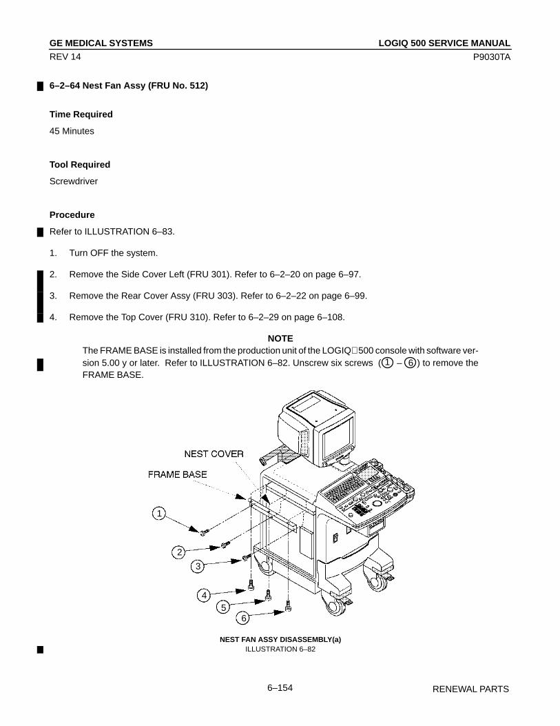
LOGIQ 500 SERVICE MANUALGE MEDICAL SYSTEMS
P9030TA
RENEWAL PARTS6–154
REV 14
6–2–64 Nest Fan Assy (FRU No. 512)
Time Required
45 Minutes
Tool Required
Screwdriver
Procedure
Refer to ILLUSTRATION 6–83.
1. Turn OFF the system.
2. Remove the Side Cover Left (FRU 301). Refer to 6–2–20 on page 6–97.
3. Remove the Rear Cover Assy (FRU 303). Refer to 6–2–22 on page 6–99.
4. Remove the Top Cover (FRU 310). Refer to 6–2–29 on page 6–108.
NOTEThe FRAME BASE is installed from the production unit of the LOGIQ 500 console with software ver-sion 5.00 y or later. Refer to ILLUSTRATION 6–82. Unscrew six screws ( 1 – 6 ) to remove theFRAME BASE.
1
2
3
45
6
NEST FAN ASSY DISASSEMBLY(a)ILLUSTRATION 6–82
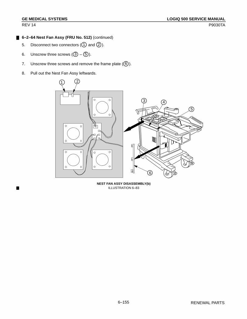
LOGIQ 500 SERVICE MANUALGE MEDICAL SYSTEMS
P9030TA
RENEWAL PARTS6–155
REV 14
6–2–64 Nest Fan Assy (FRU No. 512) (continued)
5. Disconnect two connectors ( 1 and 2 ).
6. Unscrew three screws ( 3 – 5 ).
7. Unscrew three screws and remove the frame plate ( 6 ).
8. Pull out the Nest Fan Assy leftwards.
1 2
3 4
5
6
NEST FAN ASSY DISASSEMBLY(b)ILLUSTRATION 6–83

LOGIQ 500 SERVICE MANUALGE MEDICAL SYSTEMS
P9030TA
RENEWAL PARTS6–156
REV 14
6–2–65 Probe CONN Set Assy (FRU No. 513)
Time Required40 Minutes
Tool Required
Screwdriver
Procedure
Refer to ILLUSTRATION 6–84 and ILLUSTRATION 6–85.
1. Turn OFF the system.
2. Remove the Front Base Cover (FRU 307). Refer to 6–2–26 on page 6–103.
3. Remove the Front Cover (FRU 308). Refer to 6–2–27 on page 6–104.
4. Remove the Side Cover Left (FRU 301). Refer to 6–2–20 on page 6–97.
5. Remove the Keyboard Bottom Cover (FRU 309). Refer to 6–2–28 on page 6–106.
6. Remove the HDD LED Assy (FRU 523). Refer to 6–2–72 on page 6–169.
NoteThe HDD LED Assy is not installed on the console with the new type of 3.5–inch HDD Assy (Quan-tum FireBall 1280S or newer ).
NoteWhen the customer uses the Single CWD option, the CWD2 Assy is installed on the case metal of theProbe CONN Set Assy. Remove the CWD2 Assy from the Probe CONN Set Assy removed and re–install it to the new Probe CONN Set Assy.
7. Remove the Power Switch Assy (FRU 525). Refer to 6–2–73 on page 6–170.
NoteThe FRONT SHIELD is installed from production unit of LOGIQ 500 console with software version5.00 y or later. Refer to ILLUSTRATION 6–85 on page 6–157. Unscrew the four screws ( 10 and 13 )to remove the FRONT SHIELD and BLIND METAL PLATE.
8. Disconnect one connector ( 1 ).
9. Disconnect four connectors ( 2 – 5 ).
10. Loosen two screws ( 6 and 7 ).
11. Unscrew two screws ( 8 and 9 ).
12. Slightly lift the Probe CONN Set Assy up, move it leftwards, and remove it.
13. Unscrew two screws ( 10 and 11 ).
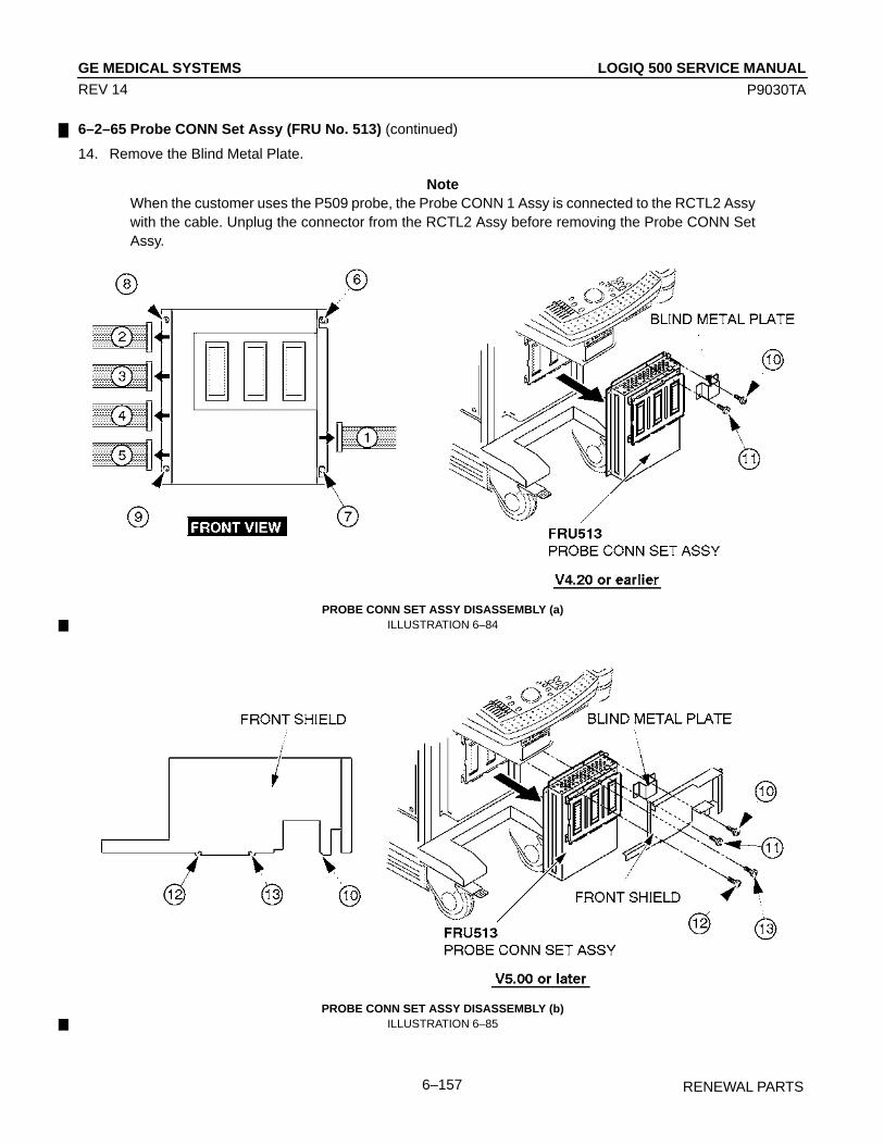
LOGIQ 500 SERVICE MANUALGE MEDICAL SYSTEMS
P9030TA
RENEWAL PARTS6–157
REV 14
6–2–65 Probe CONN Set Assy (FRU No. 513) (continued)
14. Remove the Blind Metal Plate.
NoteWhen the customer uses the P509 probe, the Probe CONN 1 Assy is connected to the RCTL2 Assywith the cable. Unplug the connector from the RCTL2 Assy before removing the Probe CONN SetAssy.
PROBE CONN SET ASSY DISASSEMBLY (a)ILLUSTRATION 6–84
PROBE CONN SET ASSY DISASSEMBLY (b)ILLUSTRATION 6–85

LOGIQ 500 SERVICE MANUALGE MEDICAL SYSTEMS
P9030TA
RENEWAL PARTS6–158
REV 14
6–2–66 Shield Finger Long (FRU No. 514), Shield Finger Short (FRU No. 515)
Time Required
45 Minutes
Tool Required
Screwdriver
Procedure
Refer to ILLUSTRATION 6–86.
1. Turn OFF the system.
2. Remove the Probe CONN Set Assy (FRU 513). Refer to 6–2–65 on page 6–156.
3. Unscrew eight screws ( 1 – 8 ).
4. Remove the connector frame.
5. Remove the Shield Finger Long (FRU 514) or Shield Finger Short (FRU 515).
Î
ÎÎÎÎÎ
ÎÎÎ
ÎÎÎÎÎÎÎÎÎÎÎÎ
SHIELD FINGER DISASSEMBLYILLUSTRATION 6–86

LOGIQ 500 SERVICE MANUALGE MEDICAL SYSTEMS
P9030TA
RENEWAL PARTS6–159
REV 14
6–2–67 Probe CONN 1 Assy (FRU No. 516)
Time Required
45 Minutes
Tool Required
Screwdriver
Procedure
Refer to ILLUSTRATION 6–87.
1. Turn OFF the system.
2. Remove the Probe CONN Set Assy (FRU 513). Refer to 6–2–65 on page 6–156.
3. Remove the Probe CONN 2 Assy (FRU 516). Refer to 6–2–68 on page 6–160.
4. Unscrew four hexagonal bolts ( 1 – 4 ).
5. Remove the Probe CONN 1 Assy.
NoteIf the customer uses the P509 Probe, the Probe CONN1 Assy for P509 Probe (2180315) is installed.In this case, you have to disconnect the connector from the RCTL2 Assy before removing ProbeCONN Set Assy.
ÎÎÎÎ
ÎÎÎÎÎÎÎÎÎÎÎÎ
ÎÎÎÎÎÎÎÎ
PROBE CONN 1 ASSY DISASSEMBLYILLUSTRATION 6–87

LOGIQ 500 SERVICE MANUALGE MEDICAL SYSTEMS
P9030TA
RENEWAL PARTS6–160
REV 14
6–2–68 Probe CONN 2 Assy (FRU No. 517)
Time Required
45 Minutes
Tool Required
Screwdriver
Procedure
Refer to ILLUSTRATION 6–88.
1. Turn OFF the system.
2. Remove the Probe CONN Set Assy (FRU 513). Refer to 6–2–65 on page 6–156.
3. Unscrew four screws ( 1 – 4 ).
4. Remove the Probe CONN 2 Assy.
Î
ÎÎÎÎÎ
ÎÎÎÎÎ
ÎÎÎÎÎÎÎÎÎÎÎ
PROBE CONN 2 ASSY DISASSEMBLYILLUSTRATION 6–88

LOGIQ 500 SERVICE MANUALGE MEDICAL SYSTEMS
P9030TA
RENEWAL PARTS6–161
REV 14
6–2–69 FDD (FRU No. 518), FDD Holder Assy (FRU No. 519)
Time Required
15 Minutes
Tool Required
Screwdriver
Procedure
Refer to ILLUSTRATION 6–89.
1. Turn OFF the system.
2. Remove the Keyboard Panel Assy (FRU 400). Refer to 6–2–41 on page 6–121.
3. Disconnect two connectors ( 1 and 2 ).
4. Unscrew four screws ( 3 – 6 ).
5. Remove the FDD Holder Assy.
6. Unscrew four screws ( 7 – 10 ).
7. Remove the FDD (FRU 518) out of the FDD Holder Assy (FRU 519).
FDD AND FDD HOLDER ASSY DISASSEMBLYILLUSTRATION 6–89

LOGIQ 500 SERVICE MANUALGE MEDICAL SYSTEMS
P9030TA
RENEWAL PARTS6–162
REV 14
6–2–70 HDD Assy (FRU No. 520), HDD Holder Assy (FRU No. 521)
Time Required
1.5 Hours
Tool Required
Screwdriver
Procedure
Refer to ILLUSTRATION 6–90 on page 6–163.
1. Make sure the customer data is saved on disks (floppy disks for system software version 1.20 or former consoleand MO disk for 2.00 or later console). Refer to 4–3–3 (D) on page 4–21, USER DATA BACK UP.
2. Turn OFF the system.
3. Remove the Keyboard Panel Assy (FRU 400). Refer to 6–2–41 on page 6–121.
4. Remove the HDDB Assy (FRU 522). Refer to 6–2–71 on page 6–168.
5. Unscrew two screws ( 1 and 2 ).
6. Remove the HDD Holder Assy.
7. Unscrew four screws ( 3 – 6 ).
8. Remove the HDD (FRU 520) out of the HDD Holder Assy (FRU 521).
NoteAfter replacing a HDD Assy with new one, the following works have to be done:
a. Set up the system preset parameters without regard to current settings. For set-up procedures, refer toLOGIQ 500 Proprietary Manual, P9030TB.
a–1. Set the Country/Zone properly. It takes approximately 40 minutes to complete this step.
a–2. Set other three parameters, Video Signal, Power Frequency and Modem Kind.
a–3. Reset the system using System Reset function of the Service Menu. Refer to LOGIQ 500 ProprietaryManual, P9030TB.
b. Install the customer data into new HDD using the back-up disk(s) after resetting the system. Refer to 4–3–3(D) on page 4–21, USER DATA BACK UP.

LOGIQ 500 SERVICE MANUALGE MEDICAL SYSTEMS
P9030TA
RENEWAL PARTS6–163
REV 14
6–2–70 HDD Assy (FRU No. 520), HDD Holder Assy (FRU No. 521) (continued)
HDD ASSY AND HDD HOLDER ASSY DISASSEMBLYILLUSTRATION 6–90
LOGIQ 500 SERVICE MANUALGE MEDICAL SYSTEMS
P9030TA
RENEWAL PARTS6–164
REV 14
6–2–70 HDD Assy (FRU No. 520), HDD Holder Assy (FRU No. 521) (continued)
3.5–Inch HDD Disassembly
Refer to ILLUSTRATION 6–91 on page 6–165.
1. Make sure the customer data is saved on MO disk. Refer to 4–3–3 (D) on page 4–21, USER DATA BACK UP.
2. Turn OFF the system.
3. Remove the Keyboard Panel Assy (FRU 400). Refer to 6–2–41 on page 6–121.
4. Unscrew two screws ( 1 and 2 ).
5. Pull out the HDD Holder2 Assy.
6. Disconnect three connectors, CB24N, CB5N, and CB45N. Refer to ILLUSTRATION 6–91 on page 6–165.
7. Unscrew four screws ( 3 – 6 ).
8. Remove the HDD (FRU 520) out of the HDD Holder2 Assy (FRU 536).
NoteAfter replacing a HDD Assy with new one, the following works have to be done:
a. Set up the system preset parameters without regard to current settings. For set-up procedures, refer toLOGIQ 500 Proprietary Manual, P9030TB.
a–1. Set the Country/Zone properly. It takes approximately 40 minutes to complete this step.
a–2. Set other three parameters, Video Signal, Power Frequency and Modem Kind.
NoteTwo additional parameters, “Power On Hardware Test” and “Trouble Image Compression”, should bealso reset for the console with system software version 2.00 or later.
NoteThe additional parameter, “Power Unit Type”, should be also reset for the console with system soft-ware version 4.00 or later.
a–3. Reset the system using System Reset function of the Service Menu. Refer to LOGIQ 500 ProprietaryManual, P9030TB.
b. Install the customer data into new HDD using the back-up disk(s) after resetting the system. Refer to 4–3–3(D) on page 4–21, USER DATA BACK UP.
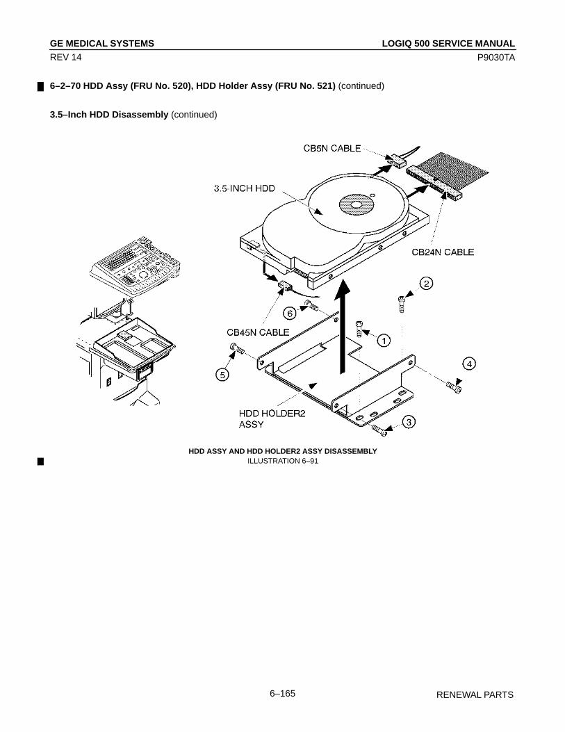
LOGIQ 500 SERVICE MANUALGE MEDICAL SYSTEMS
P9030TA
RENEWAL PARTS6–165
REV 14
6–2–70 HDD Assy (FRU No. 520), HDD Holder Assy (FRU No. 521) (continued)
3.5–Inch HDD Disassembly (continued)
HDD ASSY AND HDD HOLDER2 ASSY DISASSEMBLYILLUSTRATION 6–91
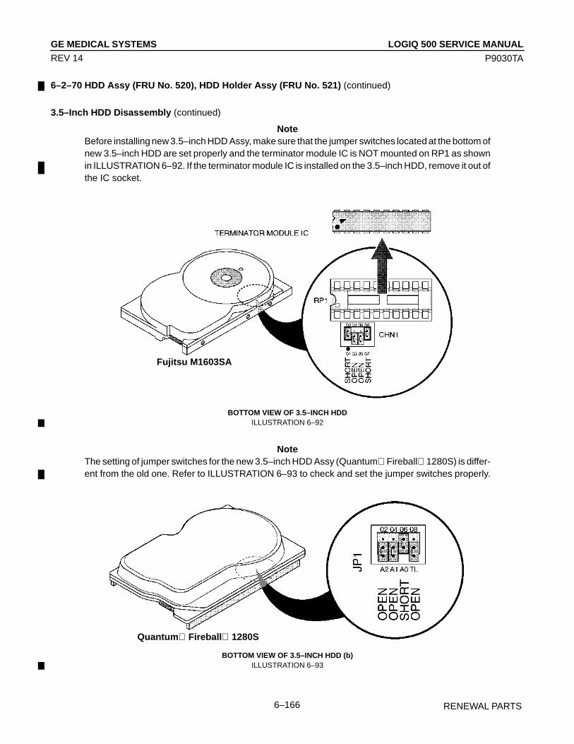
LOGIQ 500 SERVICE MANUALGE MEDICAL SYSTEMS
P9030TA
RENEWAL PARTS6–166
REV 14
6–2–70 HDD Assy (FRU No. 520), HDD Holder Assy (FRU No. 521) (continued)
3.5–Inch HDD Disassembly (continued)
NoteBefore installing new 3.5–inch HDD Assy, make sure that the jumper switches located at the bottom ofnew 3.5–inch HDD are set properly and the terminator module IC is NOT mounted on RP1 as shownin ILLUSTRATION 6–92. If the terminator module IC is installed on the 3.5–inch HDD, remove it out ofthe IC socket.
Fujitsu M1603SA
BOTTOM VIEW OF 3.5–INCH HDDILLUSTRATION 6–92
NoteThe setting of jumper switches for the new 3.5–inch HDD Assy (Quantum Fireball 1280S) is differ-ent from the old one. Refer to ILLUSTRATION 6–93 to check and set the jumper switches properly.
Quantum Fireball 1280S
BOTTOM VIEW OF 3.5–INCH HDD (b)ILLUSTRATION 6–93

LOGIQ 500 SERVICE MANUALGE MEDICAL SYSTEMS
P9030TA
RENEWAL PARTS6–167
REV 14
6–2–70 HDD Assy (FRU No. 520), HDD Holder Assy (FRU No. 521) (continued)
3.5–Inch HDD Disassembly (continued)
NoteThe setting of jumper switches for the new 3.5–inch HDD Assy (Quantum Fireball EL) is differentfrom others. Refer to ILLUSTRATION 6–94 to check and set the jumper switches properly.
Quantum Fireball EL
APPEARANCE OF 3.5–INCH HDD (QUANTUM FIREBALL EL)ILLUSTRATION 6–94

LOGIQ 500 SERVICE MANUALGE MEDICAL SYSTEMS
P9030TA
RENEWAL PARTS6–168
REV 14
6–2–71 HDDB Assy (FRU No. 522)
NoteThe HDDB Assy is not used for the console with the 3.5–inch HDD Assy.
Time Required
15 Minutes
Tool Required
Screwdriver
Procedure
Refer to ILLUSTRATION 6–95.
1. Turn OFF the system.
2. Remove the Keyboard Panel Assy (FRU 400). Refer to 6–2–41 on page 6–121.
3. Disconnect three connectors ( 1 – 3 ).
4. Unscrew four screws ( 4 – 7 ).
5. Remove the HDDB Assy.
HDDB ASSY DISASSEMBLYILLUSTRATION 6–95

LOGIQ 500 SERVICE MANUALGE MEDICAL SYSTEMS
P9030TA
RENEWAL PARTS6–169
REV 14
6–2–72 HDD LED Assy (FRU No. 523)
NoteThe HDD LED Assy is not available on the console with the new type of 3.5–inch HDD Assy (Quan-tum FireBall 1280S or newer ).
Time Required
10 Minutes
Tool Required
Screwdriver
Procedure
Refer to ILLUSTRATION 6–96.
1. Turn OFF the system.
2. Remove the Front Base Cover (FRU 307). Refer to 6–2–26 on page 6–103.
3. Remove the Front Cover (FRU 308). Refer to 6–2–27 on page 6–104.
4. Unscrew two screws ( 1 – 2 ).
5. Disconnect one connector ( 3 ).
6. Remove the HDD LED Assy.
Î
ÎÎÎÎÎÎÎÎÎ
ÎÎÎ
ÎÎÎÎÎÎ
ÎÎÎÎÎÎÎÎÎÎÎÎÎÎÎÎÎÎÎÎÎÎÎÎÎÎÎÎÎÎÎÎÎÎÎÎÎÎÎÎÎÎÎÎÎÎÎÎÎÎ
HDD LED ASSY DISASSEMBLYILLUSTRATION 6–96

LOGIQ 500 SERVICE MANUALGE MEDICAL SYSTEMS
P9030TA
RENEWAL PARTS6–170
REV 14
6–2–73 Power Switch Assy (FRU No. 525)
Time Required
10 Minutes
Tool Required
Screwdriver
Procedure
Refer to ILLUSTRATION 6–97.
NOTEThe new type of Power Switch Assy is installed from production unit of LOGIQ 500 console with soft-ware version 5.00 y or later. Refer to ILLUSTRATION 6–98 on page 6–171.
1. Turn OFF the system.
2. Remove the Front Base Cover (FRU 307). Refer to 6–2–26 on page 6–103.
3. Remove the Front Cover (FRU 308). Refer to 6–2–27 on page 6–104.
4. Disconnect one connector ( 1 ).
5. Unscrew two screws ( 2 and 3 ).
6. Remove the Power Switch Assy.
POWER SWITCH ASSY DISASSEMBLY (a)ILLUSTRATION 6–97

LOGIQ 500 SERVICE MANUALGE MEDICAL SYSTEMS
P9030TA
RENEWAL PARTS6–171
REV 14
6–2–73 Power Switch Assy (FRU No. 525)
NOTETo remove the new type of Power Switch Assy, disconnect one connector ( 1 ). Unscrew the ninescrews ( 2 – 10 ) to remove the new type of Power Switch Assy.
POWER SWITCH ASSY DISASSEMBLY (b)ILLUSTRATION 6–98
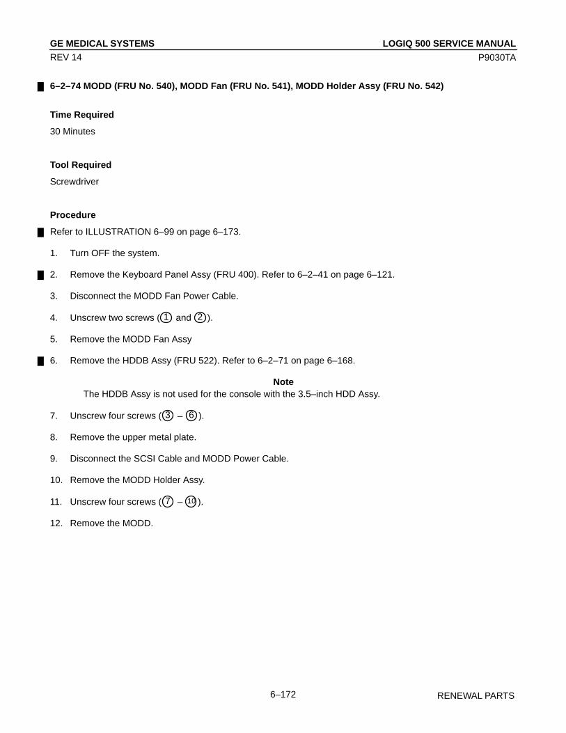
LOGIQ 500 SERVICE MANUALGE MEDICAL SYSTEMS
P9030TA
RENEWAL PARTS6–172
REV 14
6–2–74 MODD (FRU No. 540), MODD Fan (FRU No. 541), MODD Holder Assy (FRU No. 542)
Time Required
30 Minutes
Tool Required
Screwdriver
Procedure
Refer to ILLUSTRATION 6–99 on page 6–173.
1. Turn OFF the system.
2. Remove the Keyboard Panel Assy (FRU 400). Refer to 6–2–41 on page 6–121.
3. Disconnect the MODD Fan Power Cable.
4. Unscrew two screws ( 1 and 2 ).
5. Remove the MODD Fan Assy
6. Remove the HDDB Assy (FRU 522). Refer to 6–2–71 on page 6–168.
NoteThe HDDB Assy is not used for the console with the 3.5–inch HDD Assy.
7. Unscrew four screws ( 3 – 6 ).
8. Remove the upper metal plate.
9. Disconnect the SCSI Cable and MODD Power Cable.
10. Remove the MODD Holder Assy.
11. Unscrew four screws ( 7 – 10 ).
12. Remove the MODD.
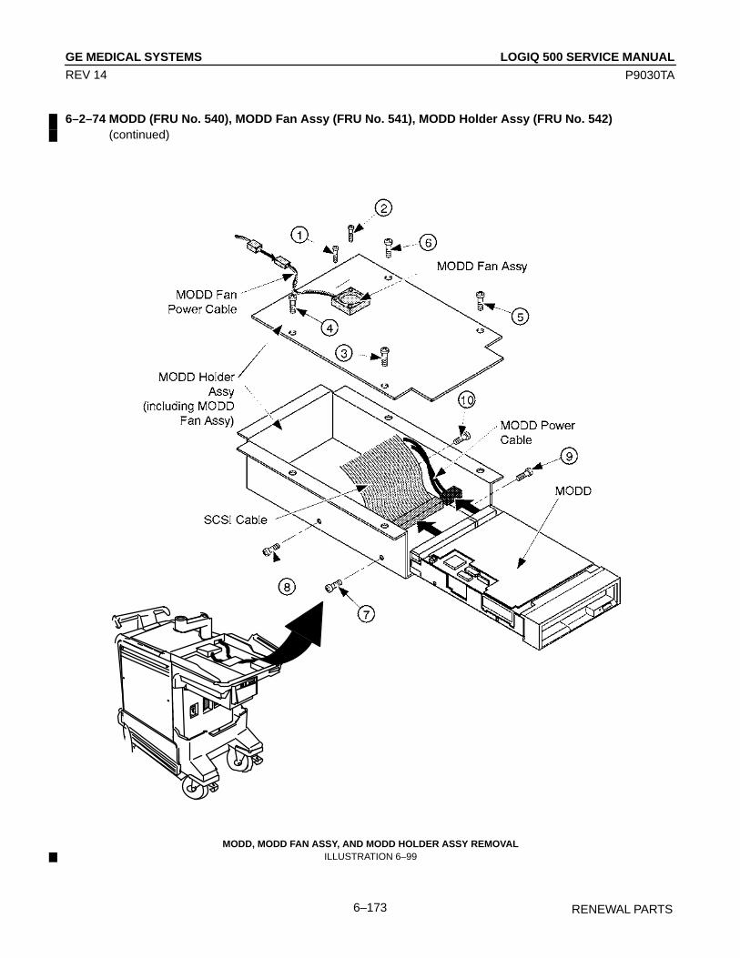
LOGIQ 500 SERVICE MANUALGE MEDICAL SYSTEMS
P9030TA
RENEWAL PARTS6–173
REV 14
6–2–74 MODD (FRU No. 540), MODD Fan Assy (FRU No. 541), MODD Holder Assy (FRU No. 542)(continued)
MODD, MODD FAN ASSY, AND MODD HOLDER ASSY REMOVALILLUSTRATION 6–99

LOGIQ 500 SERVICE MANUALGE MEDICAL SYSTEMS
P9030TA
RENEWAL PARTS6–174
REV 14
6–2–74 MODD (FRU No. 540), MODD Fan Assy (FRU No. 541), MODD Holder Assy (FRU No. 542)(continued)
NoteMake sure that the DIP switches and jumper switches located on the MODD are set as follows beforeyou install a new MODD onto the system.ILLUSTRATION 6–100 shows the settings of jumper switches when the 2.5–inch HDD is installed onthe console.
Jumper Switches for anothertype of MODD (2187012)
SETTINGS OF SWITCHES ON MODDILLUSTRATION 6–100
NoteIf the 3.5–inch HDD is installed on the console, set the jumper switches as shown inILLUSTRATION 6–101.
Jumper Switches for anothertype of MODD (2187012)
SETTINGS OF JUMPER SWITCHESILLUSTRATION 6–101

LOGIQ 500 SERVICE MANUALGE MEDICAL SYSTEMS
P9030TA
RENEWAL PARTS6–175
REV 14
6–2–74 MODD (FRU No. 540), MODD Fan Assy (FRU No. 541), MODD Holder Assy (FRU No. 542)(continued)
NoteIf the 3.5–inch HDD is installed on the console, set the jumper switches as shown inILLUSTRATION 6–102.
SETTINGS OF JUMPER SWITCHES ON MODD (2187012–2)ILLUSTRATION 6–102
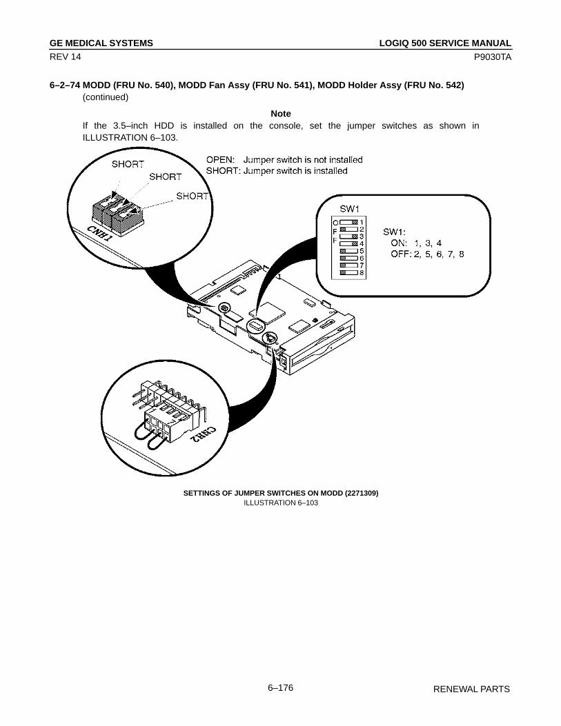
LOGIQ 500 SERVICE MANUALGE MEDICAL SYSTEMS
P9030TA
RENEWAL PARTS6–176
REV 14
6–2–74 MODD (FRU No. 540), MODD Fan Assy (FRU No. 541), MODD Holder Assy (FRU No. 542)(continued)
NoteIf the 3.5–inch HDD is installed on the console, set the jumper switches as shown inILLUSTRATION 6–103.
SETTINGS OF JUMPER SWITCHES ON MODD (2271309)ILLUSTRATION 6–103

LOGIQ 500 SERVICE MANUALGE MEDICAL SYSTEMS
P9030TA
RENEWAL PARTS6–177
REV 14
6–2–74 MODD (FRU No. 540), MODD Fan Assy (FRU No. 541), MODD Holder Assy (FRU No. 542)(continued)
Emergency Ejection
When your disk is not mounted and the eject button does not function, eject the disk following the procedure below:
CAUTION
Use the emergency ejection procedure only in emergency situations. If this procedure is usedwhile a MO disk is inserted, data in the disk can be destroyed.
1. Turn the system power OFF.
2. Unfold and straighten one end of a large wire paper clip.
3. Insert the straightened end of the clip into the emergency eject hole and press firmly.
This will eject the disk.
EMERGENCY EJECTIONILLUSTRATION 6–104

LOGIQ 500 SERVICE MANUALGE MEDICAL SYSTEMS
P9030TA
RENEWAL PARTS6–178
REV 14
This page is left blank intentionally.

LOGIQ 500 SERVICE MANUALGE MEDICAL SYSTEMS
P9030TA
RENEWAL PARTS6–179
REV 14
This page is left blank intentionally.

LOGIQ 500 SERVICE MANUALGE MEDICAL SYSTEMS
P9030TA
RENEWAL PARTS6–180
REV 14
6–2–75 P.C. Board(s) (FRU No. 601 through 610)
Time Required
10 Minutes
Tool Required
Screwdriver
Procedure
CAUTION
An electrostatic discharge may damage a component. Turn OFF power and wear the wriststrap before you remove a circuit boards. Do not unplug the power cord to keep ground conti-nuity.Do not bend or flex the boards when mounting/dismounting each board. Surface mount ICboards are very susceptible to damage from flex/torque.
Refer to ILLUSTRATION 6–105 on page 6–181.
1. Turn OFF the system.
2. Remove the Side Cover Left (FRU 301). Refer to 6–2–20 on page 6–97.
3. Unscrew the five Nest Cover screws.
4. Remove the Nest Cover.
5. Disconnect the connector if removing one of the BF16 boards. Otherwise, skip this step.
6. Move the upper and lower ejector in the direction indicated by the arrow 1 . Refer to ILLUSTRATION 6–105 onpage 6–181.
7. Pull out the board, do not bend it ( 2 ).
NoteAfter replacing a CPU Assy with new one, it is necessary to install the system ID number into the timekeeper RAM on new CPU Assy and set up two items, Video Signal and Power Frequency among foursystem preset parameters. For set-up procedures of system preset parameter, refer to LOGIQ 500Proprietary Manual, P9030TB.The system software version 2.00 or later console can be installed the system ID number into the timekeeper RAM on new CPU Assy using the utility function. Refer to Section 4–3–3 (J) on page 4–31,SYSTEM ID ENTRY/DISPLAY in Chapter 4 of this manual.For the procedure of installing system ID number into the system software version 1.20 or former con-sole, refer to LOGIQ 500 Proprietary Manual, P9030TB.
NoteIf the customer uses the P509 probe, you have to disconnect the connector from the RCTL2 Assybefore removing the RCTL2 Assy.

LOGIQ 500 SERVICE MANUALGE MEDICAL SYSTEMS
P9030TA
RENEWAL PARTS6–181
REV 14
6–2–75 P.C. Boards (FRU No. 601 through 610) (continued)
P.C. BOARD(S) REMOVALILLUSTRATION 6–105
LOGIQ 500 SERVICE MANUALGE MEDICAL SYSTEMS
P9030TA
RENEWAL PARTS6–182
REV 14
6–2–76 Time Keeper RAM (FRU No. 611)
Time Required
1 Hour
Tool Required
ScrewdriverIC Remover
Procedure
Refer to ILLUSTRATION 6–106 on page 6–183.
1. Turn OFF the system.
2. Remove the Side Cover Left (FRU 301). Refer to 6–2–20 on page 6–97.
3. Unscrew the four Nest Cover screws.
4. Remove the Nest Cover.
5. Remove the CPU Assy (FRU 610). Refer to 6–2–75 on page 6–180.
6. Remove the Time Keeper RAM.
NoteAfter replacing a time keeper RAM with new one, it is necessary to install the system ID number intonew time keeper RAM and set up two items, Video Signal and Power Frequency among four systempreset parameters. For set-up procedures of system preset parameter, refer to LOGIQ 500 Propri-etary Manual, P9030TB.The system software version 2.00 or later console can be installed the system ID number into newtime keeper RAM using the utility function. Refer to Section 4–3–3 (J) on page 4–31, SYSTEM IDENTRY/DISPLAY in Chapter 4 of this manual.For the procedure of installing system ID number into the system software version 1.20 or former con-sole, refer to LOGIQ 500 Proprietary Manual, P9030TB.

LOGIQ 500 SERVICE MANUALGE MEDICAL SYSTEMS
P9030TA
RENEWAL PARTS6–183
REV 14
6–2–76 Time Keeper RAM (FRU No. 611) (continued)
TIME KEEPER RAM REMOVALILLUSTRATION 6–106

LOGIQ 500 SERVICE MANUALGE MEDICAL SYSTEMS
P9030TA
RENEWAL PARTS6–184
REV 14
6–2–77 Time Keeper Battery (FRU No. 612)
Time Required
1 Hour
Tool Required
ScrewdriverIC Remover
Procedure
Refer to ILLUSTRATION 6–107 on page 6–185.
1. Turn OFF the system.
2. Remove the Side Cover Left (FRU 301). Refer to 6–2–20 on page 6–97.
3. Unscrew the four Nest Cover screws.
4. Remove the Nest Cover.
5. Remove the CPU Assy (FRU 610). Refer to 6–2–75 on page 6–180.
6. Remove the Time Keeper Battery.
NoteAfter replacing a time keeper battery with new one, it is necessary to install the system ID number intothe time keeper RAM and to set up the factory preset data.The system software version 2.00 or later console can be installed the system ID number into newtime keeper RAM using the utility function. Refer to Section 4–3–3 (J) on page 4–31, SYSTEM IDENTRY/DISPLAY in Chapter 4 of this manual.For the procedure of installing system ID number into the system software version 1.20 or former con-sole, refer to LOGIQ 500 Proprietary Manual, P9030TB.
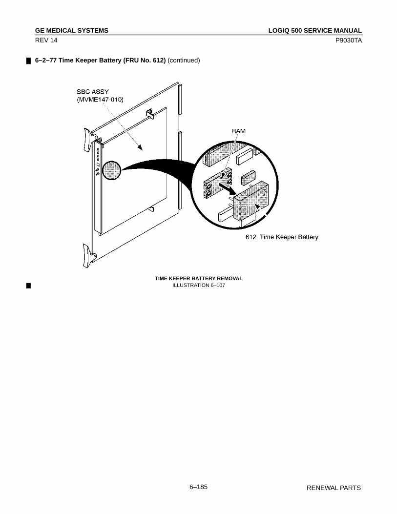
LOGIQ 500 SERVICE MANUALGE MEDICAL SYSTEMS
P9030TA
RENEWAL PARTS6–185
REV 14
6–2–77 Time Keeper Battery (FRU No. 612) (continued)
TIME KEEPER BATTERY REMOVALILLUSTRATION 6–107

LOGIQ 500 SERVICE MANUALGE MEDICAL SYSTEMS
P9030TA
RENEWAL PARTS6–186
REV 14
6–2–78 Time Keeper RAM (for MVME167–002B) (FRU No. 616)
Time Required
1 Hour
Tool Required
ScrewdriverIC Remover
Procedure
Refer to ILLUSTRATION 6–108 on page 6–187.
1. Turn OFF the system.
2. Remove the Side Cover Left (FRU 301). Refer to 6–2–20 on page 6–97.
3. Unscrew the four Nest Cover screws.
4. Remove the Nest Cover.
5. Remove the CPU–A Assy (FRU 610). Refer to 6–2–75 on page 6–180.
6. Remove the Time Keeper RAM on the SBC–A Assy (MVME167–002B).
NoteAfter replacing a time keeper RAM with new one, it is necessary to install the system ID number intothe time keeper RAM and to set up the factory preset data.

LOGIQ 500 SERVICE MANUALGE MEDICAL SYSTEMS
P9030TA
RENEWAL PARTS6–187
REV 14
6–2–78 Time Keeper RAM (for MVME167–002B) (FRU No. 616) (continued)
TIME KEEPER RAM (for MVME167–002B) REMOVALILLUSTRATION 6–108
LOGIQ 500 SERVICE MANUALGE MEDICAL SYSTEMS
P9030TA
RENEWAL PARTS6–188
REV 14
6–2–79 OMEM Assy (FRU No. 613)
Time Required
20 Minutes
Tool Required
Screwdriver
Procedure
CAUTION
Do not bend or flex the boards when mounting/dismounting the piggyback boards. Surfacemount IC boards are very susceptible to damage from flex/torque.
Refer to ILLUSTRATION 6–109 on page 6–189.
1. Turn OFF the system.
2. Remove the Side Cover Left (FRU 301). Refer to 6–2–20 on page 6–97.
3. Unscrew the four Nest Cover screws.
4. Remove the Nest Cover.
5. Remove the TLMC Assy (FRU 606). Refer to 6–2–75 on page 6–180, P.C. Board(s).
6. Unscrew one screw ( 1 ).
7. Remove the OMEM Assy out of the TLMC Assy.

LOGIQ 500 SERVICE MANUALGE MEDICAL SYSTEMS
P9030TA
RENEWAL PARTS6–189
REV 14
6–2–79 OMEM Assy (FRU No. 613) (continued)
OMEM ASSY DISASSEMBLYILLUSTRATION 6–109
LOGIQ 500 SERVICE MANUALGE MEDICAL SYSTEMS
P9030TA
RENEWAL PARTS6–190
REV 14
6–2–80 Nest Mother Assy (FRU No. 614)
Time Required
2 Hours
Tool Required
ScrewdriverHexagonal Wrench
Procedure
Refer to ILLUSTRATION 6–110 on page 6–192.
CAUTION
An electrostatic discharge may damage a component. Turn OFF power and wear the wriststrap before you remove a circuit boards. Do not unplug the power cord to keep ground conti-nuity.
CAUTION
Do not bend or flex the boards when mounting/dismounting each board. Surface mount ICboards are very susceptible to damage from flex/torque.
1. Turn OFF the system.
2. Remove the Side Cover Left (FRU 301). Refer to 6–2–20 on page 6–97.
3. Remove the Front Base Cover (FRU 307). Refer to 6–2–26 on page 6–103.
4. Remove the Side Cover Right (FRU 302). Refer to 6–2–21 on page 6–98.
5. Remove the Rear Cover Assy (FRU 303). Refer to 6–2–22 on page 6–99.
6. Remove the Front Cover (FRU 308). Refer to 6–2–27 on page 6–104.
7. Remove the Top Cover (FRU 310). Refer to 6–2–29 on page 6–108.
8. Unscrew the four Nest Cover screws.
9. Remove the Nest Cover.
10. Remove all the P.C. Boards. Refer to 6–2–75 on page 6–180.

LOGIQ 500 SERVICE MANUALGE MEDICAL SYSTEMS
P9030TA
RENEWAL PARTS6–191
REV 14
6–2–80 Nest Mother Assy (FRU No. 614) (continued)
11. Remove the Rear CONN Panel Assy (FRU 501). Refer to 6–2–53 on page 6–138.
12. Remove the HDD LED Assy (FRU 523). Refer to 6–2–72 on page 6–169.
13. Remove the Power Switch Assy (FRU 525). Refer to 6–2–73 on page 6–170.
14. Remove the Probe CONN Set Assy (FRU 513). Refer to 6–2–65 on page 6–156.
NoteWhen the customer uses the Single CWD option, the CWD2 Assy is installed on the case metal of theProbe CONN Set Assy. Remove the CWD2 Assy before removing the Probe CONN Set Assy.
15. Unscrew two screws and remove the CONN Assy holding plate.
16. Remove the Nest Fan Assy (FRU 512). Refer to 6–2–64 on page 6–154.
17. Remove the Neck Assy (FRU 201). Refer to 6–2–17 on page 6–92.
18. Disconnect sixteen connectors connected with the mother board.
19. Unscrew four hexagonal bolts to remove the four power line connected on the mother board.
20. Unscrew four hexagonal bolts ( 1 – 4 ) on the left side of the console. Refer to ILLUSTRATION 6–110 on page6–192.
21. Unscrew three hexagonal bolts ( 5 – 7 ) on the right side of the console. Refer to ILLUSTRATION 6–110 onpage 6–192.
22. Remove the Nest Mother Assy (FRU No. 614).

LOGIQ 500 SERVICE MANUALGE MEDICAL SYSTEMS
P9030TA
RENEWAL PARTS6–192
REV 14
6–2–80 Nest Mother Assy (FRU No. 614) (continued)
NEST MOTHER ASSY DISASSEMBLYILLUSTRATION 6–110

LOGIQ 500 SERVICE MANUALGE MEDICAL SYSTEMS
P9030TA
RENEWAL PARTS6–193
REV 14
6–2–81 Mother IC (FRU No. 615)
Time Required
1 Hour
Tool Required
ScrewdriverHexagonal Wrench
Procedure
Refer to ILLUSTRATION 6–111.
1. Turn OFF the system.
2. Remove the Front Base Cover (FRU 307). Refer to 6–2–26 on page 6–103.
3. Remove the Side Cover Right (FRU 302). Refer to 6–2–21 on page 6–98.
4. Remove the Rear Cover Assy (FRU 303). Refer to 6–2–22 on page 6–99.
5. Remove the Neck Assy (FRU 201). Refer to 6–2–17 on page 6–92.
6. Remove the Mother IC.
MOTHER IC REMOVALILLUSTRATION 6–111

LOGIQ 500 SERVICE MANUALGE MEDICAL SYSTEMS
P9030TA
RENEWAL PARTS6–194
REV 14
6–2–82 DNID2 Assy (FRU No. 620)
NoteThe DNID2 Assy is supplied with the optional Single CWD upgrade kit.
Time Required
20 Minutes
Tool Required
Screwdriver
Procedure
CAUTION
Do not bend or flex the boards when mounting/dismounting the piggyback boards. Surfacemount IC boards are very susceptible to damage from flex/torque.
Refer to ILLUSTRATION 6–112 on page 6–195.
1. Turn OFF the system.
2. Remove the Side Cover Left (FRU 301). Refer to 6–2–20 on page 6–97.
3. Unscrew the four Nest Cover screws.
4. Remove the Nest Cover.
5. Disconnect the CB16J62 connector from the J2 connector on the DNID2 Assy.
6. Remove the ANLP2 Assy (FRU 602) installed in slot 4. Refer to 6–2–75, P.C. Board(s) on page 6–180.
7. Unscrew one screw ( 1 ).
8. Remove the DNID2 Assy out of the ANLP2 Assy.

LOGIQ 500 SERVICE MANUALGE MEDICAL SYSTEMS
P9030TA
RENEWAL PARTS6–195
REV 14
6–2–82 DNID2 Assy (FRU No. 620) (continued)
DNID2 ASSY DISASSEMBLYILLUSTRATION 6–112

LOGIQ 500 SERVICE MANUALGE MEDICAL SYSTEMS
P9030TA
RENEWAL PARTS6–196
REV 14
This page is left blank intentionally.

LOGIQ 500 SERVICE MANUALGE MEDICAL SYSTEMS
P9030TA
RENEWAL PARTS6–197
REV 14
This page is left blank intentionally.
LOGIQ 500 SERVICE MANUALGE MEDICAL SYSTEMS
P9030TA
RENEWAL PARTS6–198
REV 14
6–2–83 A1 PS +5V 32A (FRU No. 701)
Time Required
30 Minutes
Tool Required
ScrewdriverHexagonal Wrench (Key Size: 3 mm)
Procedure
Refer to ILLUSTRATION 6–113 on page 6–199.
1. Turn OFF the system.
2. Remove the Front Base Cover (FRU 307). Refer to 6–2–26 on page 6–103.
3. Remove the Side Cover Right (FRU 302). Refer to 6–2–21 on page 6–98.
4. Unscrew five screws ( 1 – 5 ).
5. Remove the PS Cover Right.
6. Slide the transparent cover ( 6 ) upwards and remove it.
7. Unscrew two screws ( 7 and 8 ).
8. Remove the two cables ( 9 and 10 ).
9. Unscrew one hexagonal bolt ( 11 ).
10. Pull the A1 PS +5V 32A outwards.
11. Unscrew two screws (12 and 13 ).
12. Remove the four cables (14 – 17 ).
13. Disconnect one connector (18 ).

LOGIQ 500 SERVICE MANUALGE MEDICAL SYSTEMS
P9030TA
RENEWAL PARTS6–199
REV 14
6–2–83 A1 PS +5V 32A (FRU No. 701) (continued)
A1 PS +5V 32A DISASSEMBLYILLUSTRATION 6–113

LOGIQ 500 SERVICE MANUALGE MEDICAL SYSTEMS
P9030TA
RENEWAL PARTS6–200
REV 14
6–2–84 A2 PS –5.2V 11A (FRU No. 702)
Time Required
30 Minutes
Tool Required
ScrewdriverHexagonal Wrench (Key Size: 3 mm)
Procedure
Refer to ILLUSTRATION 6–114 on page 6–201.
1. Turn OFF the system.
2. Remove the Front Base Cover (FRU 307). Refer to 6–2–26 on page 6–103.
3. Remove the Side Cover Right (FRU 302). Refer to 6–2–21 on page 6–98.
4. Remove the PS Cover Right. Refer to 6–2–83 on page 6–198.
5. Slide the transparent cover ( 1 ) upwards and remove it.
6. Unscrew six screws ( 2 – 7 ).
7. Remove the eight cables ( 8 – 15 ).
8. Unscrew one hexagonal bolt (16 ).
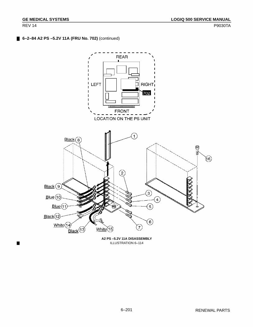
LOGIQ 500 SERVICE MANUALGE MEDICAL SYSTEMS
P9030TA
RENEWAL PARTS6–201
REV 14
6–2–84 A2 PS –5.2V 11A (FRU No. 702) (continued)
A2 PS –5.2V 11A DISASSEMBLYILLUSTRATION 6–114
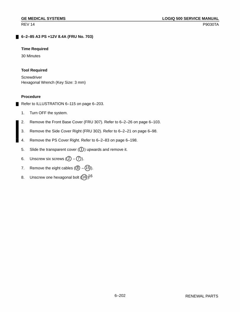
LOGIQ 500 SERVICE MANUALGE MEDICAL SYSTEMS
P9030TA
RENEWAL PARTS6–202
REV 14
6–2–85 A3 PS +12V 8.4A (FRU No. 703)
Time Required
30 Minutes
Tool Required
ScrewdriverHexagonal Wrench (Key Size: 3 mm)
Procedure
Refer to ILLUSTRATION 6–115 on page 6–203.
1. Turn OFF the system.
2. Remove the Front Base Cover (FRU 307). Refer to 6–2–26 on page 6–103.
3. Remove the Side Cover Right (FRU 302). Refer to 6–2–21 on page 6–98.
4. Remove the PS Cover Right. Refer to 6–2–83 on page 6–198.
5. Slide the transparent cover ( 1 ) upwards and remove it.
6. Unscrew six screws ( 2 – 7 ).
7. Remove the eight cables ( 8 – 15 ).
8. Unscrew one hexagonal bolt (16 16).

LOGIQ 500 SERVICE MANUALGE MEDICAL SYSTEMS
P9030TA
RENEWAL PARTS6–203
REV 14
6–2–85 A3 PS +12V 8.4A (FRU No. 703) (continued)
A3 PS +12V 8.4A DISASSEMBLYILLUSTRATION 6–115

LOGIQ 500 SERVICE MANUALGE MEDICAL SYSTEMS
P9030TA
RENEWAL PARTS6–204
REV 14
6–2–86 A4 PS –12V 2.5A (FRU No. 704)
Time Required
30 Minutes
Tool Required
ScrewdriverHexagonal Wrench (Key Size: 3 mm)
Procedure
Refer to ILLUSTRATION 6–116 on page 6–205.
1. Turn OFF the system.
2. Remove the Front Base Cover (FRU 307). Refer to 6–2–26 on page 6–103.
3. Remove the Side Cover Right (FRU 302). Refer to 6–2–21 on page 6–98.
4. Remove the PS Cover Right. Refer to 6–2–83 on page 6–198.
5. Slide the transparent cover ( 1 ) upwards and remove it.
6. Unscrew four screws ( 2 – 5 ).
7. Remove the six cables ( 6 – 11 ).
8. Unscrew one hexagonal bolt (12 ).
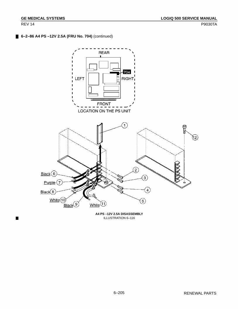
LOGIQ 500 SERVICE MANUALGE MEDICAL SYSTEMS
P9030TA
RENEWAL PARTS6–205
REV 14
6–2–86 A4 PS –12V 2.5A (FRU No. 704) (continued)
A4 PS –12V 2.5A DISASSEMBLYILLUSTRATION 6–116

LOGIQ 500 SERVICE MANUALGE MEDICAL SYSTEMS
P9030TA
RENEWAL PARTS6–206
REV 14
6–2–87 A5 PS +5V 30A (FRU No. 705)
Time Required
30 Minutes
Tool Required
ScrewdriverHexagonal Wrench (Key Size: 3 mm)
Procedure
Refer to ILLUSTRATION 6–117 on page 6–207.
1. Turn OFF the system.
2. Remove the Front Base Cover (FRU 307). Refer to 6–2–26 on page 6–103.
3. Remove the Side Cover Right (FRU 302). Refer to 6–2–21 on page 6–98.
4. Remove the PS Cover Right. Refer to 6–2–83 on page 6–198.
5. Slide the transparent cover ( 1 ) upwards and remove it.
6. Unscrew two screws ( 2 and 3 ).
7. Remove the four cables ( 4 – 7 ).
8. Unscrew one hexagonal bolt ( 8 ).
9. Pull the A2 PS –5.2V 11A outwards.
10. Unscrew two screws ( 9 and 10 ).
11. Remove the four cables ( 11 – 14 ).
12. Disconnect one connector (15 ).

LOGIQ 500 SERVICE MANUALGE MEDICAL SYSTEMS
P9030TA
RENEWAL PARTS6–207
REV 14
6–2–87 A5 PS +5V 30A (FRU No. 705) (continued)
A5 PS +5V 30A DISASSEMBLYILLUSTRATION 6–117

LOGIQ 500 SERVICE MANUALGE MEDICAL SYSTEMS
P9030TA
RENEWAL PARTS6–208
REV 14
6–2–88 A7 SW Cont Assy (FRU No. 706)
Time Required
30 Minutes
Tool Required
ScrewdriverHexagonal Wrench (Key Size: 3 mm)
Procedure
Refer to ILLUSTRATION 6–118 on page 6–209.
1. Turn OFF the system.
2. Remove the Front Base Cover (FRU 307). Refer to 6–2–26 on page 6–103.
3. Remove the Side Cover Right (FRU 302). Refer to 6–2–21 on page 6–98.
4. Remove the PS Cover Right. Refer to 6–2–83 on page 6–198.
5. Unscrew one hexagonal bolt ( 1 ).
6. Pull the SW Cont Assy outwards and disconnect four connectors ( 2 – 5 ).
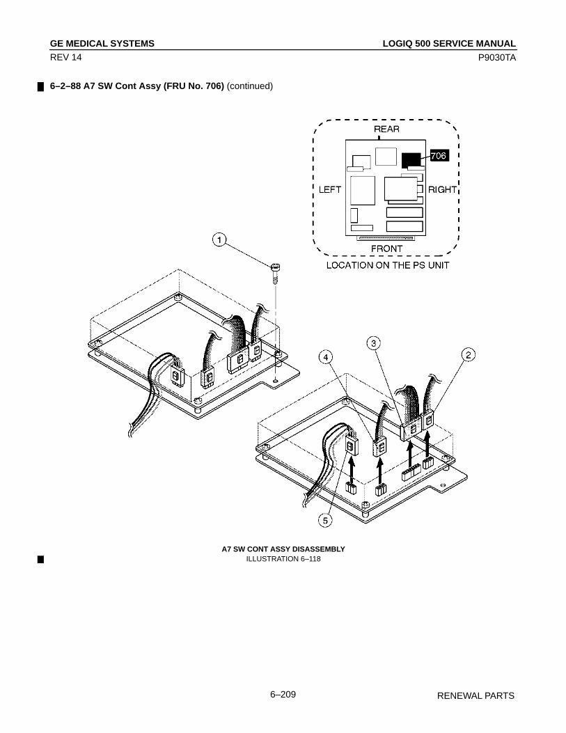
LOGIQ 500 SERVICE MANUALGE MEDICAL SYSTEMS
P9030TA
RENEWAL PARTS6–209
REV 14
6–2–88 A7 SW Cont Assy (FRU No. 706) (continued)
A7 SW CONT ASSY DISASSEMBLYILLUSTRATION 6–118
LOGIQ 500 SERVICE MANUALGE MEDICAL SYSTEMS
P9030TA
RENEWAL PARTS6–210
REV 14
6–2–89 A8 PFC Assy (FRU No. 707)
Time Required
30 Minutes
Tool Required
Screwdriver
Procedure
Refer to ILLUSTRATION 6–119 on page 6–211.
1. Turn OFF the system.
2. Remove the Front Base Cover (FRU 307). Refer to 6–2–26 on page 6–103.
3. Remove the Side Cover Right (FRU 302). Refer to 6–2–21 on page 6–98.
4. Remove the PS Cover Right. Refer to 6–2–83 on page 6–198.
5. Remove the transparent cover ( 1 ).
6. Unscrew two screws ( 3 and 4 ).
7. Remove the two cables ( 5 and 6 ).
8. Remove the transparent cover ( 2 ).
9. Unscrew four screws ( 7 – 10 ).
10. Remove the seven cables ( 11 – 17 ).
11. Disconnect one connector (18 ).
12. Unscrew two screws (19 and 20 ).
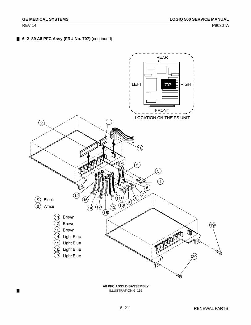
LOGIQ 500 SERVICE MANUALGE MEDICAL SYSTEMS
P9030TA
RENEWAL PARTS6–211
REV 14
6–2–89 A8 PFC Assy (FRU No. 707) (continued)
A8 PFC ASSY DISASSEMBLYILLUSTRATION 6–119
LOGIQ 500 SERVICE MANUALGE MEDICAL SYSTEMS
P9030TA
RENEWAL PARTS6–212
REV 14
6–2–90 A10 HV REG Assy (FRU No. 708)
Time Required
30 Minutes
Tool Required
ScrewdriverHexagonal Wrench (Key Size: 3 mm)
Procedure
Refer to ILLUSTRATION 6–120 on page 6–213.
1. Turn OFF the system.
2. Remove the Side Cover Left (FRU 301). Refer to 6–2–20 on page 6–97.
3. Unscrew five screws ( 1 – 5 ).
4. Remove the PS Cover Left.
5. Unscrew one screw ( 6 ).
6. Pull the HV REG Assy outwards and disconnect seven connectors ( 7 – 13 ).
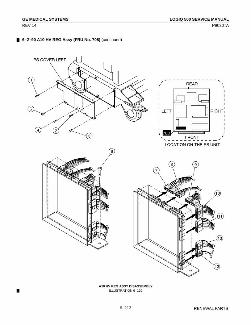
LOGIQ 500 SERVICE MANUALGE MEDICAL SYSTEMS
P9030TA
RENEWAL PARTS6–213
REV 14
6–2–90 A10 HV REG Assy (FRU No. 708) (continued)
A10 HV REG ASSY DISASSEMBLYILLUSTRATION 6–120

LOGIQ 500 SERVICE MANUALGE MEDICAL SYSTEMS
P9030TA
RENEWAL PARTS6–214
REV 14
6–2–91 RL1 & 2 Assy (FRU No. 709)
Time Required
30 Minutes
Tool Required
Screwdriver
Procedure
Refer to ILLUSTRATION 6–121 on page 6–215.
1. Turn OFF the system.
2. Remove the Side Cover Left (FRU 301). Refer to 6–2–20 on page 6–97.
3. Remove the PS Cover Left. Refer to 6–2–90 on page 6–212.
4. Unscrew eight screws ( 1 – 8 ).
5. Disconnect eight connectors ( 9 – 16 ).
6. Unscrew two screws (17 and 18 ).

LOGIQ 500 SERVICE MANUALGE MEDICAL SYSTEMS
P9030TA
RENEWAL PARTS6–215
REV 14
6–2–91 RL1 & 2 Assy (FRU No. 709) (continued)
RL1 & 2 ASSY DISASSEMBLYILLUSTRATION 6–121

LOGIQ 500 SERVICE MANUALGE MEDICAL SYSTEMS
P9030TA
RENEWAL PARTS6–216
REV 14
6–2–92 RL3 (FRU No. 710)
Time Required
30 Minutes
Tool Required
Screwdriver
Procedure
Refer to ILLUSTRATION 6–122 on page 6–217.
1. Turn OFF the system.
2. Remove the Side Cover Left (FRU 301). Refer to 6–2–20 on page 6–97.
3. Remove the PS Cover Left. Refer to 6–2–90 on page 6–212.
4. Pull four cables out by hand ( 1 – 4 ).
5. Unscrew two screws ( 5 and 6 ).
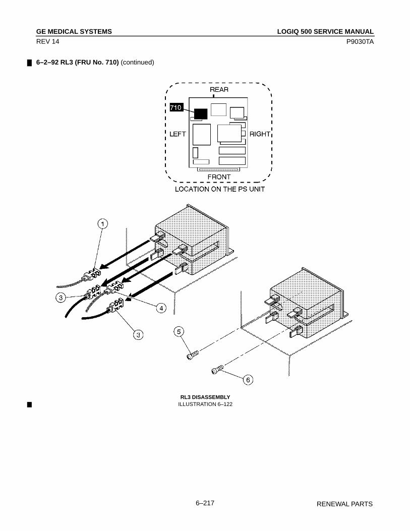
LOGIQ 500 SERVICE MANUALGE MEDICAL SYSTEMS
P9030TA
RENEWAL PARTS6–217
REV 14
6–2–92 RL3 (FRU No. 710) (continued)
RL3 DISASSEMBLYILLUSTRATION 6–122

LOGIQ 500 SERVICE MANUALGE MEDICAL SYSTEMS
P9030TA
RENEWAL PARTS6–218
REV 14
6–2–93 PS Fan Set (FRU No. 713)
Time Required
30 Minutes
Tool Required
Screwdriver
Procedure
Refer to ILLUSTRATION 6–123 on page 6–219.
1. Turn OFF the system.
2. Remove the Side Cover Left (FRU 301). Refer to 6–2–20 on page 6–97.
3. Remove the PS Cover Left. Refer to 6–2–83 on page 6–198.
4. Unscrew two screws ( 1 and 2 ).
5. Disconnect one connector ( 3 ).
6. Remove the Front Base Cover (FRU 307). Refer to 6–2–26 on page 6–103.
7. Remove the Side Cover Right (FRU 302). Refer to 6–2–21 on page 6–98.
8. Remove the PS Cover Right. Refer to 6–2–90 on page 6–212.
9. Unscrew two screws ( 4 and 5 ).
10. Disconnect one connector ( 6 ).
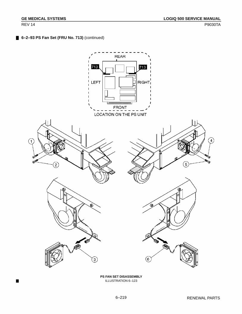
LOGIQ 500 SERVICE MANUALGE MEDICAL SYSTEMS
P9030TA
RENEWAL PARTS6–219
REV 14
6–2–93 PS Fan Set (FRU No. 713) (continued)
PS FAN SET DISASSEMBLYILLUSTRATION 6–123
LOGIQ 500 SERVICE MANUALGE MEDICAL SYSTEMS
P9030TA
RENEWAL PARTS6–220
REV 14
6–2–94 Breaker 20A (FRU No. 714), Breaker 7.5A (FRU No. 715)
Time Required
30 Minutes
Tool Required
Screwdriver
Procedure
Refer to ILLUSTRATION 6–124 on page 6–221.
1. Turn OFF the system.
2. Remove the Rear Cover Assy (FRU 303). Refer to 6–2–22 on page 6–99.
3. Unscrew four screws ( 1 – 4 ).
4. Remove the PS Rear Panel.
5. Unscrew two screws ( 5 and 6 ).
6. Unscrew four screws ( 7 – 10 ).
7. Remove four cables ( 11 – 14 ).
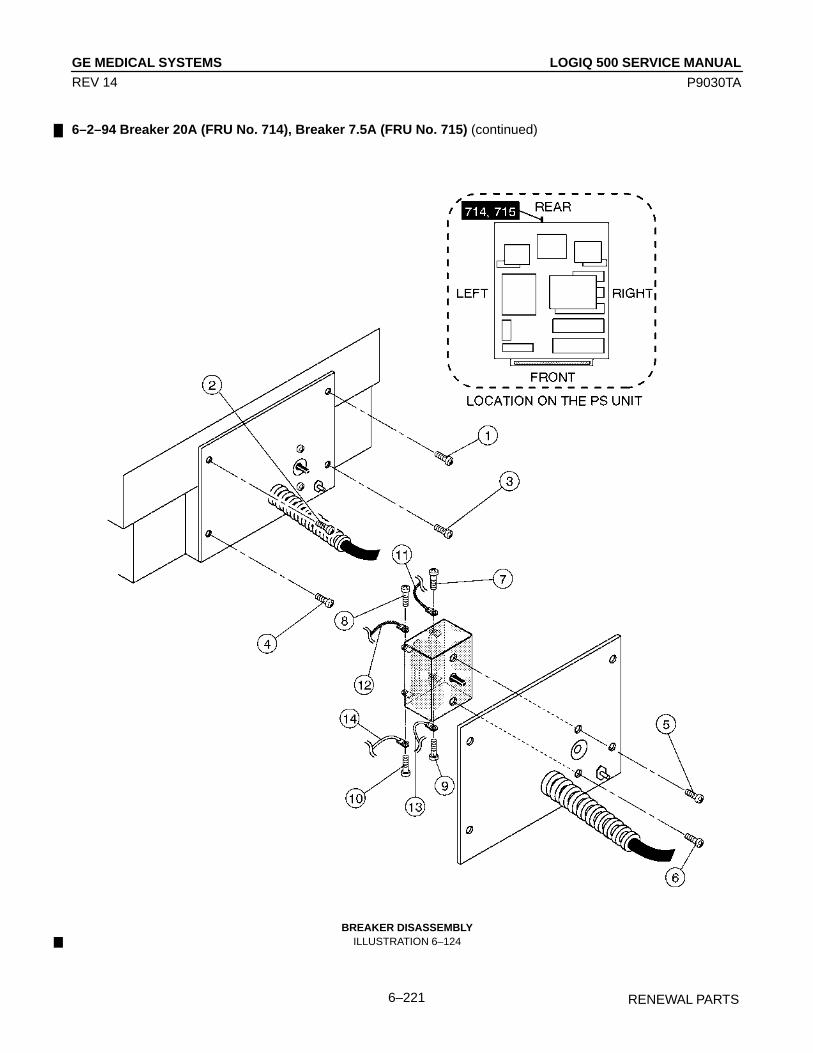
LOGIQ 500 SERVICE MANUALGE MEDICAL SYSTEMS
P9030TA
RENEWAL PARTS6–221
REV 14
6–2–94 Breaker 20A (FRU No. 714), Breaker 7.5A (FRU No. 715) (continued)
BREAKER DISASSEMBLYILLUSTRATION 6–124
LOGIQ 500 SERVICE MANUALGE MEDICAL SYSTEMS
P9030TA
RENEWAL PARTS6–222
REV 14
6–2–95 Inlet Unit 120V, Inlet Unit 220V (FRU No. 720)
Time Required
30 Minutes
Tool Required
Screwdriver
Procedure
Refer to ILLUSTRATION 6–125 on page 6–223.
1. Turn OFF the system.
2. Remove the Rear Cover Assy (FRU 303). Refer to 6–2–22 on page 6–99.
3. Remove the Power Supply Unit. Refer to 6–5–2 on page 6–243.
4. Unscrew four screws ( 1 – 4 ). Refer to ILLUSTRATION 6–124 on page 6–221.
5. Remove the transparent plastic cover.
6. Unscrew two screws ( 5 and 6 ) and remove the two cables.
7. Unscrew one screw ( 7 ).
8. Pull the Ground Wire out by hand.
9. Unscrew two screws ( 8 and 9 ) and remove the two cables.
10. Cut two Tie Wraps and remove them.
11. Remove the Inlet Unit.

LOGIQ 500 SERVICE MANUALGE MEDICAL SYSTEMS
P9030TA
RENEWAL PARTS6–223
REV 14
6–2–95 Inlet Unit 120V, Inlet Unit 220V (FRU No. 720) (continued)
INLET UNIT DISASSEMBLYILLUSTRATION 6–125

LOGIQ 500 SERVICE MANUALGE MEDICAL SYSTEMS
P9030TA
RENEWAL PARTS6–224
REV 14
6–2–96 Inrush Limiter 120V, Inrush Limiter 220V (FRU No. 721)
Time Required
30 Minutes
Tool Required
Screwdriver
Hexagonal Wrench
Procedure
Refer to ILLUSTRATION 6–126 on page 6–225.
1. Turn OFF the system.
2. Remove the Rear Cover Assy (FRU 303). Refer to 6–2–22 on page 6–99.
3. Remove the Power Supply Unit. Refer to 6–5–2 on page 6–243.
4. Unscrew four screws ( 1 – 4 ). Refer to ILLUSTRATION 6–124 on page 6–221.
5. Remove the A7 SW Cont Assy (FRU No. 706). Refer to 6–2–88 on page 6–208.
6. Unscrew two nuts ( 5 and 6 ) and remove the two cables.
7. Remove the transparent plastic cover.
8. Unscrew two screws ( 7 and 8 ) and remove the two cables.
9. Unscrew two screws ( 9 and 10 ).
10. Pull two cables out by hand ( 11 and 12 ).
11. Remove the Inrush Limiter (FRU 721).

LOGIQ 500 SERVICE MANUALGE MEDICAL SYSTEMS
P9030TA
RENEWAL PARTS6–225
REV 14
6–2–96 Inrush Limiter 120V, Inrush Limiter 220V (FRU No. 721) (continued)
INTUSH LIMITER DISASSEMBLYILLUSTRATION 6–126

LOGIQ 500 SERVICE MANUALGE MEDICAL SYSTEMS
P9030TA
RENEWAL PARTS6–226
REV 14
This page is left blank intentionally.

LOGIQ 500 SERVICE MANUALGE MEDICAL SYSTEMS
P9030TA
RENEWAL PARTS6–227
REV 14
6–3 FUSE REPLACEMENT
6–3–1 Introduction
LOGIQ 500 has sixteen replaceable fuses. The table below states the items of those fuses.
TABLE 6–1REPLACEABLE FUSES
LOCATION Ref. No. RATING REMARKS
REAR1 ASSY F1 1A 250V
F1 800mA 250V
F2 1.6A 250V
F3 5A 500V For 110V model
F1 500mA 250V
F2 500mA 250V
A8 PFC ASSY F1 8A 250V
F1 800mA 250V
F2 350mA 250V
F3 800mA 250V
F4 6.3A 125V
A10 HV REG ASSY F5 630mA 250V
F6 630mA 250V
F7 350mA 250V
F8 350mA 250V
F9 350mA 250V
A7SW CONT ASSY
TB3
INSIDE
POWER
SUPPLY
UNIT
6–3–2 Replacement Procedures
Concerning replacing each fuse of LOGIQ 500, refer to the following steps;
NoteThis system contains no operator serviceable parts inside. Please refer servicing to qualified person-nel from GE. (See Address of Chapter 1.)
Parts Required
FRU PART NAME QTY PART # REMARKS801 Fuse Set 1 P9522RF
Tools Required
ScrewdriverHexagonal Wrench (Key Size: 3mm)

LOGIQ 500 SERVICE MANUALGE MEDICAL SYSTEMS
P9030TA
RENEWAL PARTS6–228
REV 14
6–3–2 Replacement Procedures (continued)
(A) F1 on REAR1 Assy
1. Turn the system power OFF. Follow the OSHA Lockout/Tagout Requirements (29 CFR 1910.147, Direction46–015902).
2. Remove the Side Cover Right (FRU302). Refer to sub–section 6–2–21 on page 6–98.
3. Replace the defective fuse with new one. Make sure that only fuse with the required rated current and of sametype is used for replacement. For the removal of the F1 fuse, refer to ILLUSTRATION 6–127.
4. After replacing Fuse, re-install the Side Cover Right.
REMOVING FUSE (F1) FROM REAR1 ASSYILLUSTRATION 6–127
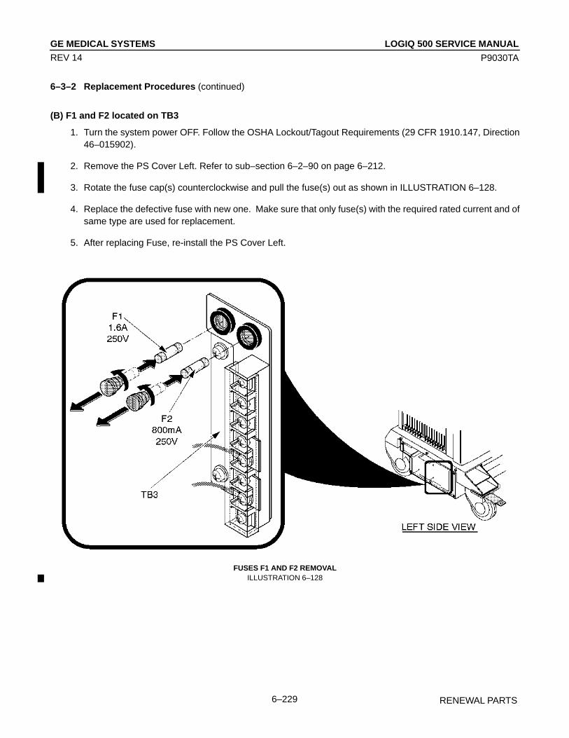
LOGIQ 500 SERVICE MANUALGE MEDICAL SYSTEMS
P9030TA
RENEWAL PARTS6–229
REV 14
6–3–2 Replacement Procedures (continued)
(B) F1 and F2 located on TB3
1. Turn the system power OFF. Follow the OSHA Lockout/Tagout Requirements (29 CFR 1910.147, Direction46–015902).
2. Remove the PS Cover Left. Refer to sub–section 6–2–90 on page 6–212.
3. Rotate the fuse cap(s) counterclockwise and pull the fuse(s) out as shown in ILLUSTRATION 6–128.
4. Replace the defective fuse with new one. Make sure that only fuse(s) with the required rated current and ofsame type are used for replacement.
5. After replacing Fuse, re-install the PS Cover Left.
FUSES F1 AND F2 REMOVALILLUSTRATION 6–128
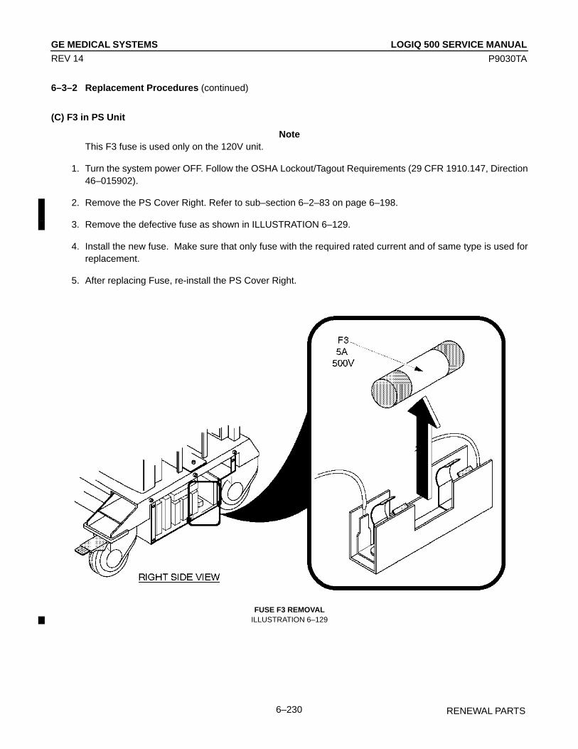
LOGIQ 500 SERVICE MANUALGE MEDICAL SYSTEMS
P9030TA
RENEWAL PARTS6–230
REV 14
6–3–2 Replacement Procedures (continued)
(C) F3 in PS Unit
NoteThis F3 fuse is used only on the 120V unit.
1. Turn the system power OFF. Follow the OSHA Lockout/Tagout Requirements (29 CFR 1910.147, Direction46–015902).
2. Remove the PS Cover Right. Refer to sub–section 6–2–83 on page 6–198.
3. Remove the defective fuse as shown in ILLUSTRATION 6–129.
4. Install the new fuse. Make sure that only fuse with the required rated current and of same type is used forreplacement.
5. After replacing Fuse, re-install the PS Cover Right.
FUSE F3 REMOVALILLUSTRATION 6–129
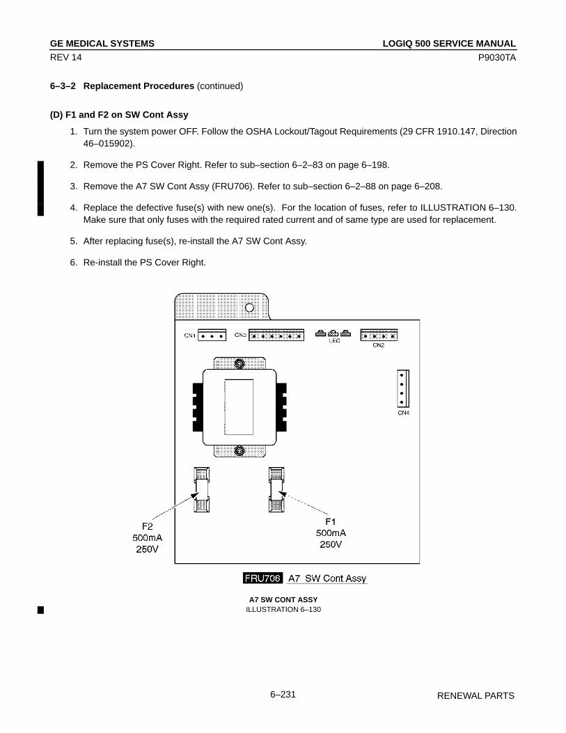
LOGIQ 500 SERVICE MANUALGE MEDICAL SYSTEMS
P9030TA
RENEWAL PARTS6–231
REV 14
6–3–2 Replacement Procedures (continued)
(D) F1 and F2 on SW Cont Assy
1. Turn the system power OFF. Follow the OSHA Lockout/Tagout Requirements (29 CFR 1910.147, Direction46–015902).
2. Remove the PS Cover Right. Refer to sub–section 6–2–83 on page 6–198.
3. Remove the A7 SW Cont Assy (FRU706). Refer to sub–section 6–2–88 on page 6–208.
4. Replace the defective fuse(s) with new one(s). For the location of fuses, refer to ILLUSTRATION 6–130.Make sure that only fuses with the required rated current and of same type are used for replacement.
5. After replacing fuse(s), re-install the A7 SW Cont Assy.
6. Re-install the PS Cover Right.
A7 SW CONT ASSYILLUSTRATION 6–130

LOGIQ 500 SERVICE MANUALGE MEDICAL SYSTEMS
P9030TA
RENEWAL PARTS6–232
REV 14
6–3–2 Replacement Procedures (continued)
(E) F1 on PFC Assy
1. Turn the system power OFF. Follow the OSHA Lockout/Tagout Requirements (29 CFR 1910.147, Direction46–015902).
2. Remove the PS Cover Right. Refer to sub–section 6–2–83 on page 6–198.
3. Remove the A8 PFC Assy (FRU707). Refer to sub–section 6–2–89 on page 6–210.
4. Replace the defective fuse with new one. For the location of fuse, refer to ILLUSTRATION 6–131. Make surethat only fuse with the required rated current and of same type is used for replacement.
5. After replacing fuse, re-install the A8 PFC Assy.
6. Re-install the PS Cover Right.
A8 PFC ASSYILLUSTRATION 6–131

LOGIQ 500 SERVICE MANUALGE MEDICAL SYSTEMS
P9030TA
RENEWAL PARTS6–233
REV 14
6–3–2 Replacement Procedures (continued)
(F) F1 through F9 on HV REG Assy
1. Turn the system power OFF. Follow the OSHA Lockout/Tagout Requirements (29 CFR 1910.147, Direction46–015902).
2. Remove the PS Cover Left. Refer to sub–section 6–2–90 on page 6–212.
3. Remove the A10 HV REG Assy (FRU708). Refer to sub–section 6–2–90 on page 6–212.
4. Replace the defective fuse(s) with new one(s). For the location of fuses, refer to ILLUSTRATION 6–132.Make sure that only fuse with the required rated current and of same type is used for replacement.
5. After replacing fuse, re-install the A10 HV REG Assy.
6. Re-install the PS Cover Left.
A10 HV REG ASSYILLUSTRATION 6–132

LOGIQ 500 SERVICE MANUALGE MEDICAL SYSTEMS
P9030TA
RENEWAL PARTS6–234
REV 14
This page is left blank intentionally.
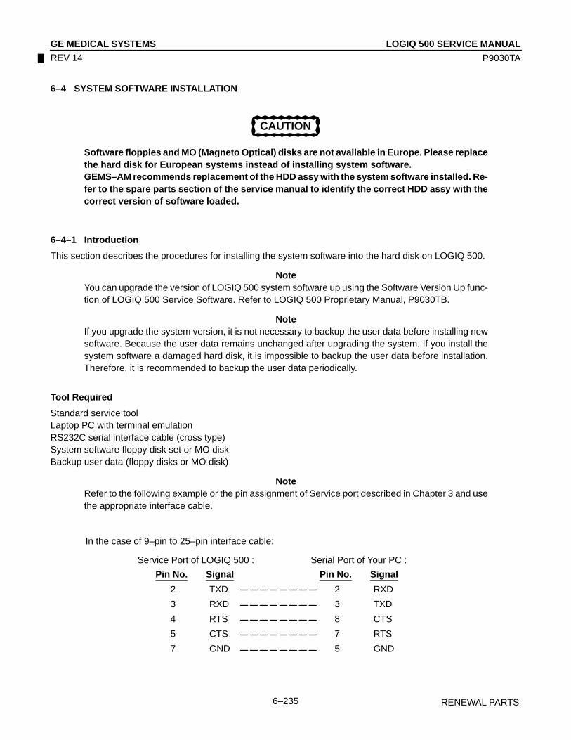
LOGIQ 500 SERVICE MANUALGE MEDICAL SYSTEMS
P9030TA
RENEWAL PARTS6–235
REV 14
6–4 SYSTEM SOFTWARE INSTALLATION
CAUTION
Software floppies and MO (Magneto Optical) disks are not available in Europe. Please replacethe hard disk for European systems instead of installing system software.GEMS–AM recommends replacement of the HDD assy with the system software installed. Re-fer to the spare parts section of the service manual to identify the correct HDD assy with thecorrect version of software loaded.
6–4–1 Introduction
This section describes the procedures for installing the system software into the hard disk on LOGIQ 500.
NoteYou can upgrade the version of LOGIQ 500 system software up using the Software Version Up func-tion of LOGIQ 500 Service Software. Refer to LOGIQ 500 Proprietary Manual, P9030TB.
NoteIf you upgrade the system version, it is not necessary to backup the user data before installing newsoftware. Because the user data remains unchanged after upgrading the system. If you install thesystem software a damaged hard disk, it is impossible to backup the user data before installation.Therefore, it is recommended to backup the user data periodically.
Tool Required
Standard service toolLaptop PC with terminal emulationRS232C serial interface cable (cross type)System software floppy disk set or MO diskBackup user data (floppy disks or MO disk)
NoteRefer to the following example or the pin assignment of Service port described in Chapter 3 and usethe appropriate interface cable.
In the case of 9–pin to 25–pin interface cable:
Service Port of LOGIQ 500 :
Pin No. Signal
2 TXD
3 RXD
4 RTS
5 CTS
7 GND
Serial Port of Your PC :
Pin No. Signal
2 RXD
3 TXD
8 CTS
7 RTS
5 GND

LOGIQ 500 SERVICE MANUALGE MEDICAL SYSTEMS
P9030TA
RENEWAL PARTS6–236
REV 14
6–4–2 Preparing before Installation
1. Turn the system power OFF.
2. Unplug the system. Follow the OSHA Lockout/Tagout Requirements (29 CFR 1910.147, Direction 46–015902).
3. Replace the hard disk with new one if necessary. Refer to sub-section 6–2–70 on page 6–162 for the replacementprocedure of hard disk.
4. Connect the RS232C cable with the serial port of the Laptop PC. Refer to ILLUSTRATION 6–133.
5. Connect the connector of another side with the Service port located at the rear side of the LOGIQ 500 as shownin ILLUSTRATION 6–133.
NoteYou may have to disconnect the insite connection.
CHARACTER TERMINAL CONNECTIONILLUSTRATION 6–133
6. Plug the system into a dedicated power receptacle.
7. Plug the Laptop PC into a wall outlet.
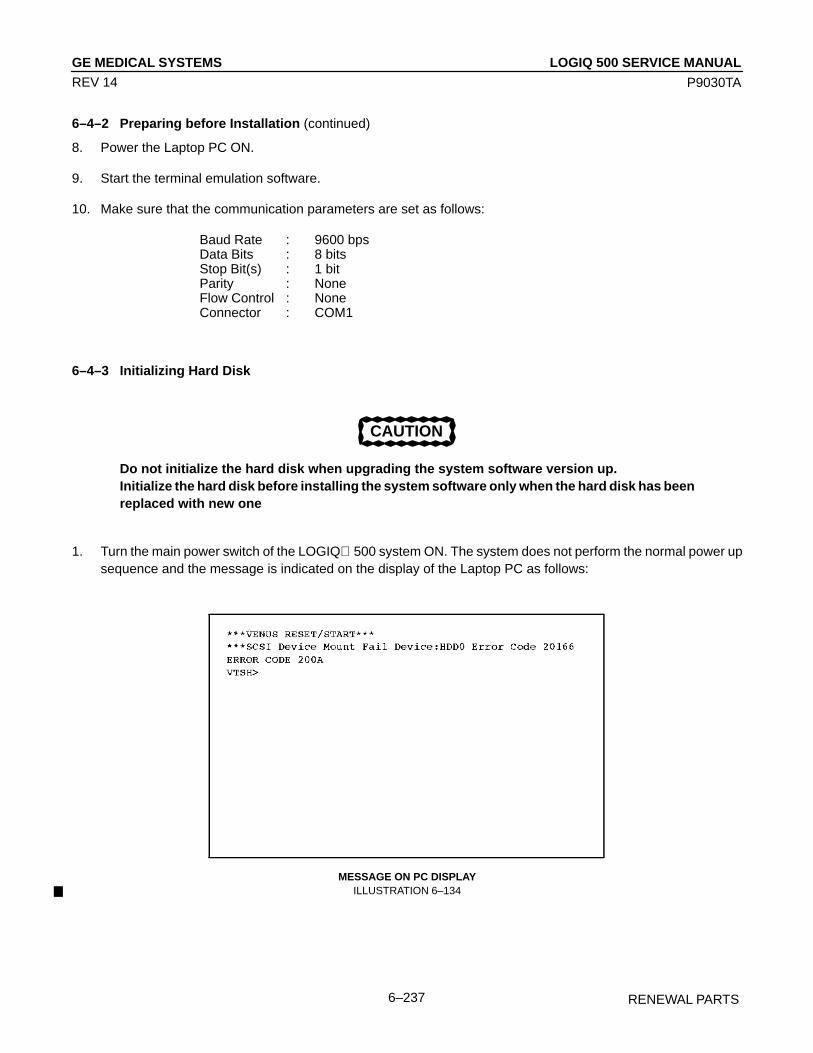
LOGIQ 500 SERVICE MANUALGE MEDICAL SYSTEMS
P9030TA
RENEWAL PARTS6–237
REV 14
6–4–2 Preparing before Installation (continued)
8. Power the Laptop PC ON.
9. Start the terminal emulation software.
10. Make sure that the communication parameters are set as follows:
Baud Rate : 9600 bpsData Bits : 8 bitsStop Bit(s) : 1 bitParity : NoneFlow Control : NoneConnector : COM1
6–4–3 Initializing Hard Disk
CAUTION
Do not initialize the hard disk when upgrading the system software version up.Initialize the hard disk before installing the system software only when the hard disk has beenreplaced with new one
1. Turn the main power switch of the LOGIQ 500 system ON. The system does not perform the normal power upsequence and the message is indicated on the display of the Laptop PC as follows:
MESSAGE ON PC DISPLAYILLUSTRATION 6–134
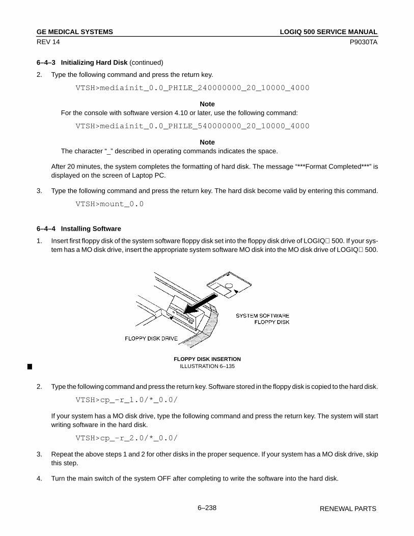
LOGIQ 500 SERVICE MANUALGE MEDICAL SYSTEMS
P9030TA
RENEWAL PARTS6–238
REV 14
6–4–3 Initializing Hard Disk (continued)
2. Type the following command and press the return key.
VTSH>mediainit_0.0_PHILE_240000000_20_10000_4000
NoteFor the console with software version 4.10 or later, use the following command:
VTSH>mediainit_0.0_PHILE_540000000_20_10000_4000
NoteThe character “_” described in operating commands indicates the space.
After 20 minutes, the system completes the formatting of hard disk. The message “***Format Completed***” isdisplayed on the screen of Laptop PC.
3. Type the following command and press the return key. The hard disk become valid by entering this command.
VTSH>mount_0.0
6–4–4 Installing Software
1. Insert first floppy disk of the system software floppy disk set into the floppy disk drive of LOGIQ 500. If your sys-tem has a MO disk drive, insert the appropriate system software MO disk into the MO disk drive of LOGIQ 500.
FLOPPY DISK INSERTIONILLUSTRATION 6–135
2. Type the following command and press the return key. Software stored in the floppy disk is copied to the hard disk.
VTSH>cp_–r_1.0/*_0.0/
If your system has a MO disk drive, type the following command and press the return key. The system will startwriting software in the hard disk.
VTSH>cp_–r_2.0/*_0.0/
3. Repeat the above steps 1 and 2 for other disks in the proper sequence. If your system has a MO disk drive, skipthis step.
4. Turn the main switch of the system OFF after completing to write the software into the hard disk.

LOGIQ 500 SERVICE MANUALGE MEDICAL SYSTEMS
P9030TA
RENEWAL PARTS6–239
REV 14
6–4–4 Installing Software (continued)
5. Turn the Laptop PC power OFF.
6. Disconnect the interface cable from the system.
6–4–5 Final Procedures
1. Turn the system power ON.
2. Check that the version number of the system software displayed on the CRT monitor screen during the power upsequence is correct.
3. Set up the system preset parameters without regard to current settings. For set-up procedures, refer to LOGIQ500 Proprietary Manual, P9030TB.
3–1 Set the Country/Zone properly. It takes approximately 40 minutes to complete this step.
3–2. Set other three parameters, Video Signal, Power Frequency and Modem Kind.
3–3. Reset the system using System Reset function of the Service Menu. Refer to LOGIQ 500 Proprietary Manu-al, P9030TB.
4. Perform functional checks to verify that the system is functioning properly. Refer to Chapter 4, FUNCTIONALCHECKS, in this manual.
5. Load the back-up user data into the system. For the procedure of loading back-up user data, refer to sub-section4–3–3, Utility Menu in Chapter 4, FUNCTIONAL CHECKS.
6. This completes the installation of the LOGIQ 500 system software.
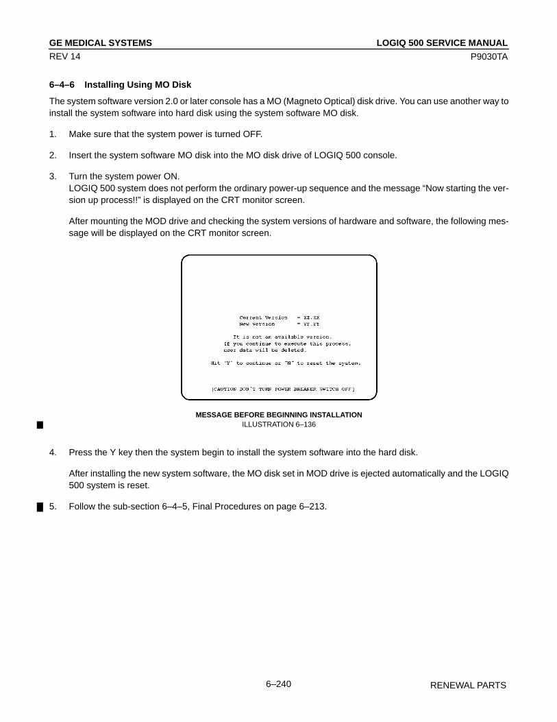
LOGIQ 500 SERVICE MANUALGE MEDICAL SYSTEMS
P9030TA
RENEWAL PARTS6–240
REV 14
6–4–6 Installing Using MO Disk
The system software version 2.0 or later console has a MO (Magneto Optical) disk drive. You can use another way toinstall the system software into hard disk using the system software MO disk.
1. Make sure that the system power is turned OFF.
2. Insert the system software MO disk into the MO disk drive of LOGIQ 500 console.
3. Turn the system power ON.LOGIQ 500 system does not perform the ordinary power-up sequence and the message “Now starting the ver-sion up process!!” is displayed on the CRT monitor screen.
After mounting the MOD drive and checking the system versions of hardware and software, the following mes-sage will be displayed on the CRT monitor screen.
MESSAGE BEFORE BEGINNING INSTALLATIONILLUSTRATION 6–136
4. Press the Y key then the system begin to install the system software into the hard disk.
After installing the new system software, the MO disk set in MOD drive is ejected automatically and the LOGIQ500 system is reset.
5. Follow the sub-section 6–4–5, Final Procedures on page 6–213.

LOGIQ 500 SERVICE MANUALGE MEDICAL SYSTEMS
P9030TA
RENEWAL PARTS6–241
REV 14
This page is left blank intentionally.

LOGIQ 500 SERVICE MANUALGE MEDICAL SYSTEMS
P9030TA
RENEWAL PARTS6–242
REV 14
This page is left blank intentionally.
LOGIQ 500 SERVICE MANUALGE MEDICAL SYSTEMS
P9030TA
RENEWAL PARTS6–243
REV 14
6–5 POWER SUPPLY REPLACEMENT
6–5–1 Introduction
This section describes the procedures for replacing the power supply unit of LOGIQ 500.
6–5–2 Replacement Procedure
READ and UNDERSTAND these instructions thoroughly before proceeding with the replacement. Perform each stepin sequence and check it off when completed. If a problem occurs after completion, go back through the procedure andcheck for implementation errors before contacting your Ultrasound Region Engineer.
CAUTION
Possible operational damage. Failure to strictly follow ESD (Electrostatic Discharge) precau-tions during this upgrade may cause constant or intermittent operational abnormalities.Strictly follow all precautions.
Check each step as it is completed.
Parts Required
FRU PART NAME QTY PART # REMARKS717 Power Supply AC110V 1 P9523DB for 110–120V model718 Power Supply AC220V 1 P9523DA for 220–240V model
Time Required
Approximately four (4) hours
Tools Required
Standard field Service Tool kitThree JacksPallet (Height: 70mm, Width and Depth: suitable length)

LOGIQ 500 SERVICE MANUALGE MEDICAL SYSTEMS
P9030TA
RENEWAL PARTS6–244
REV 14
6–5–2 Replacement Procedure (continued)
(A) Removing Monitor, Covers, and Neck Assy
1. Turn the system power OFF and unplug the unit.
2. Lift and set the Monitor to the highest position by pushing down the Up/down Release Button located on the NeckAssy.
3. Remove the Monitor Assy. Refer to 6–2–1 on page 6–66.
CAUTION
Personal injury hazard. If you remove the monitor assy without lifting monitor arm up to high-est position, pushing the Up/down Release Button causes the monitor arm to spring up withgreat force. This may cause personal injury. Do not push the Up/down Release Button afterremoving the monitor assy.
4. Remove the Side Cover Left. Refer to 6–2–20 on page 6–97.
5. Remove the Front Base Cover. Refer to 6–2–26 on page 6–103.
6. Remove the Side Cover Right. Refer to 6–2–21 on page 6–98.
7. Remove the Rear Cover Assy. Refer to 6–2–22 on page 6–99.
8. Remove the Neck Assy. Refer to 6–2–17 on page 6–92.
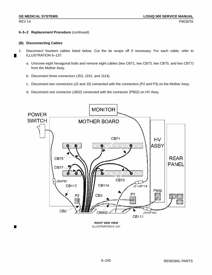
LOGIQ 500 SERVICE MANUALGE MEDICAL SYSTEMS
P9030TA
RENEWAL PARTS6–245
REV 14
6–5–2 Replacement Procedure (continued)
(B) Disconnecting Cables
1. Disconnect fourteen cables listed below. Cut the tie wraps off if necessary. For each cable, refer toILLUSTRATION 6–137.
a. Unscrew eight hexagonal bolts and remove eight cables (two CB71, two CB73, two CB75, and two CB77)from the Mother Assy.
b. Disconnect three connectors (J53, J101, and J114).
c. Disconnect two connectors (J2 and J3) connected with the connectors (P2 and P3) on the Mother Assy.
d. Disconnect one connector (J902) connected with the connector (P902) on HV Assy.
RIGHT SIDE VIEWILLUSTRATION 6–137

LOGIQ 500 SERVICE MANUALGE MEDICAL SYSTEMS
P9030TA
RENEWAL PARTS6–246
REV 14
6–5–2 Replacement Procedure (continued)
(C) Replacing Power Supply
1. Place three jacks at the positions indicated in ILLUSTRATION 6–138.
2. Make sure that the jacks are evenly seated on the floor and the flat surface of the console.
3. Make sure that the jacks can support the complete load of the console.
PLACING JACKSILLUSTRATION 6–138

LOGIQ 500 SERVICE MANUALGE MEDICAL SYSTEMS
P9030TA
RENEWAL PARTS6–247
REV 14
6–5–2 Replacement Procedure (continued)
2. Lift the system up using the jacks by approximately 30mm. Be careful to keep the console horizontally as much asyou can.
3. Insert the pallet between the floor and the Power Supply unit. Refer to ILLUSTRATION 6–139.
PALLET INSERTIONILLUSTRATION 6–139
4. Lower the console and put the console on the pallet.

LOGIQ 500 SERVICE MANUALGE MEDICAL SYSTEMS
P9030TA
RENEWAL PARTS6–248
REV 14
6–5–2 Replacement Procedure (continued)
5. Unscrew six hexagonal bolts. Three bolts are located at the right side and other three bolts are located at the leftside.
6. Lift the console up using the jacks by approximately 100mm to pull the cables out of the console. Refer toILLUSTRATION 6–140.
POWER SUPPLY UNIT REMOVAL (a)ILLUSTRATION 6–140
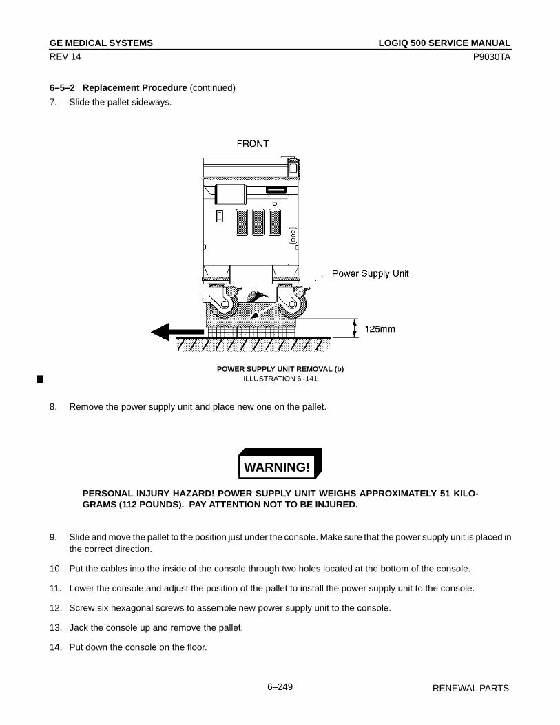
LOGIQ 500 SERVICE MANUALGE MEDICAL SYSTEMS
P9030TA
RENEWAL PARTS6–249
REV 14
6–5–2 Replacement Procedure (continued)
7. Slide the pallet sideways.
POWER SUPPLY UNIT REMOVAL (b)ILLUSTRATION 6–141
8. Remove the power supply unit and place new one on the pallet.
WARNING!
PERSONAL INJURY HAZARD! POWER SUPPLY UNIT WEIGHS APPROXIMATELY 51 KILO-GRAMS (112 POUNDS). PAY ATTENTION NOT TO BE INJURED.
9. Slide and move the pallet to the position just under the console. Make sure that the power supply unit is placed inthe correct direction.
10. Put the cables into the inside of the console through two holes located at the bottom of the console.
11. Lower the console and adjust the position of the pallet to install the power supply unit to the console.
12. Screw six hexagonal screws to assemble new power supply unit to the console.
13. Jack the console up and remove the pallet.
14. Put down the console on the floor.

LOGIQ 500 SERVICE MANUALGE MEDICAL SYSTEMS
P9030TA
RENEWAL PARTS6–250
REV 14
6–5–2 Replacement Procedure (continued)
(D) Final Procedure
1. Connect fourteen cables with the appropriate connectors. For the details of cables, refer to 6–5–2 (B), Discon-necting Cables on page 6–219.
2. Re–assemble the removal parts. Refer to section 6–2, DISASSEMBLY/RE-ASSEMBLY.
3. Plug the system and power it ON.
4. Perform all power supply checks and leakage current test. Refer to 7–3, ELECTRICAL SAFETY TEST in Chap-ter 7.
5. Perform functional checks to verify that the system is functioning properly. Refer to Chapter 4, FUNCTIONALCHECKS, in this manual.
6. This completes the replacement of the Power Supply Unit.
LOGIQ 500 SERVICE MANUALGE MEDICAL SYSTEMS
P9030TA
RENEWAL PARTS6–251
REV 14
6–6 REPLACING 2.5–INCH HDD ASSY WITH 3.5–INCH HDD ASSY
6–6–1 Introduction
This section provides the installation procedures of the 3.5–Inch HDD Assy using the Installation Kit for LOGIQ 500console.
6–6–2 Time Required
1 hour
6–6–3 Parts Required
ITEM PART NAME QTY PART # REMARKS1. 3.5–inch HDD Assy 2 Part number is different
depending on the softwareversion.
2. HDD Replacement Kit 1 2160057HDD Holder2 Assy 1 2145973 For 3.5–inch HDD AssyCB24N Cable Assy 1 2145889 MOD and HDD to MOTHERCB5N Cable Assy 1 2145890 HDD to MOTHERCB45N Cable Assy 1 2145891 HDD to HDD LED Ass
through CB46Screw 4Screw 2Tie Wrap 2 200mm
6–6–4 Procedures
(A) Removing 2.5–inch HDD Assy, HDDB Assy and Cables
1. Turn the main power switch OFF.
2. Wait a while until the power off process is completed.
3. Set the circuit breaker located at the rear of Power Supply unit to OFF position (lower side).
4. Unplug the unit. Follow the OSHA Lockout/Tagout Requirements (29 CFR 1910.147, Direction 46–015902).
5. Remove the Keyboard Panel Assy. Refer to 6–2–41 on page 6–121.
6. Remove the Front Base Cover. Refer to 6–2–26 on page 6–103.
7. Remove the Side Cover Right. Refer to 6–2–21 on page 6–98.

LOGIQ 500 SERVICE MANUALGE MEDICAL SYSTEMS
P9030TA
RENEWAL PARTS6–252
REV 14
6–6–4 Procedures (continued)
(A) Removing 2.5–inch HDD Assy, HDDB Assy and Cables (continued)
8. Cut the three tie wraps and remove them. Refer to ILLUSTRATION 6–142.
REMOVING HDDB ASSYILLUSTRATION 6–142

LOGIQ 500 SERVICE MANUALGE MEDICAL SYSTEMS
P9030TA
RENEWAL PARTS6–253
REV 14
6–6–4 Procedures (continued)
(A) Removing 2.5–inch HDD Assy, HDDB Assy and Cables (continued)
9. Unscrew four screws and remove the MODD Cover Metal.
REMOVING MODD COVER METALILLUSTRATION 6–143
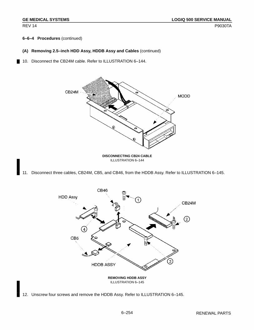
LOGIQ 500 SERVICE MANUALGE MEDICAL SYSTEMS
P9030TA
RENEWAL PARTS6–254
REV 14
6–6–4 Procedures (continued)
(A) Removing 2.5–inch HDD Assy, HDDB Assy and Cables (continued)
10. Disconnect the CB24M cable. Refer to ILLUSTRATION 6–144.
DISCONNECTING CB24 CABLEILLUSTRATION 6–144
11. Disconnect three cables, CB24M, CB5, and CB46, from the HDDB Assy. Refer to ILLUSTRATION 6–145.
REMOVING HDDB ASSYILLUSTRATION 6–145
12. Unscrew four screws and remove the HDDB Assy. Refer to ILLUSTRATION 6–145.

LOGIQ 500 SERVICE MANUALGE MEDICAL SYSTEMS
P9030TA
RENEWAL PARTS6–255
REV 14
6–6–4 Procedures (continued)
(A) Removing 2.5–inch HDD Assy, HDDB Assy and Cables (continued)
13. Unscrew two screws and remove the 2.5–inch HDD Assy with HDD Holder Assy. Refer to ILLUSTRATION 6–146.
REMOVING 2.5–INCH HDD ASSYILLUSTRATION 6–146
14. Remove the Rear CONN Panel Assy (FRU 501). Refer to 6–2–53 on page 6–138.
15. Disconnect the CB24M cable from the Mother Assy and Rear1 Assy and the CB5 cable from the Mother Assy.Refer to ILLUSTRATION 6–147.
REMOVING CABLESILLUSTRATION 6–147
16. Remove the CB24M and CB5 cables.
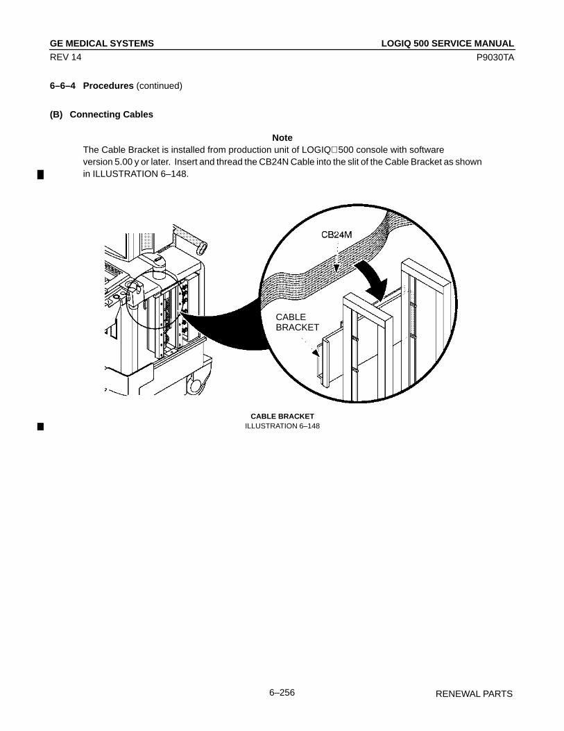
LOGIQ 500 SERVICE MANUALGE MEDICAL SYSTEMS
P9030TA
RENEWAL PARTS6–256
REV 14
6–6–4 Procedures (continued)
(B) Connecting Cables
NoteThe Cable Bracket is installed from production unit of LOGIQ 500 console with software version 5.00 y or later. Insert and thread the CB24N Cable into the slit of the Cable Bracket as shownin ILLUSTRATION 6–148.
CABLEBRACKET
CABLE BRACKETILLUSTRATION 6–148

LOGIQ 500 SERVICE MANUALGE MEDICAL SYSTEMS
P9030TA
RENEWAL PARTS6–257
REV 14
6–6–4 Procedures (continued)
(B) Connecting Cables (continued)
17. Connect the CB24N Cable with the P24A connector on the Mother Assy. Refer to ILLUSTRATION 6–149.
18. Connect the CB5N Cable with the P5A connector on the Mother Assy. Refer to ILLUSTRATION 6–149.
CONNECTING CABLESILLUSTRATION 6–149
19. Pass another side of cables through the opening of Frame forward to the MODD and HDD.

LOGIQ 500 SERVICE MANUALGE MEDICAL SYSTEMS
P9030TA
RENEWAL PARTS6–258
REV 14
6–6–4 Procedures (continued)
(C) Installing 3.5–Inch HDD Assy
20. Make sure that the four jumper switch are set as shown in ILLUSTRATION 6–150.
21. Make sure that the Terminator Module IC is not mounted on the 3.5–inch HDD Assy. Refer to ILLUSTRATION 6–150.
Fujitsu M1603SA
TERMINATOR MODULE ICILLUSTRATION 6–150
NoteThe setting of jumper switches for the new 3.5–inch HDD Assy (Quantum Fireball TM 1280S) is dif-ferent from the old one. Refer to ILLUSTRATION 6–151 to check and set the jumper switches properly.
Quantum Fireball 1280S
BOTTOM VIEW OF 3.5–INCH HDD (b)ILLUSTRATION 6–151
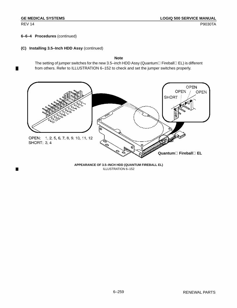
LOGIQ 500 SERVICE MANUALGE MEDICAL SYSTEMS
P9030TA
RENEWAL PARTS6–259
REV 14
6–6–4 Procedures (continued)
(C) Installing 3.5–Inch HDD Assy (continued)
NoteThe setting of jumper switches for the new 3.5–inch HDD Assy (Quantum Fireball EL) is differentfrom others. Refer to ILLUSTRATION 6–152 to check and set the jumper switches properly.
Quantum Fireball EL
APPEARANCE OF 3.5–INCH HDD (QUANTUM FIREBALL EL)ILLUSTRATION 6–152

LOGIQ 500 SERVICE MANUALGE MEDICAL SYSTEMS
P9030TA
RENEWAL PARTS6–260
REV 14
6–6–4 Procedures (continued)
(C) Installing 3.5–Inch HDD Assy (continued)
22. Connect the CB45N cable with the 3.5–inch HDD Assy. Refer to ILLUSTRATION 6–153.
23. Connect another side of the CB45N cable to the CB46 cable.
24. Set the 3.5–inch HDD Assy on the HDD Holder2 Assy. Refer to ILLUSTRATION 6–153.
25. Screw four screws supplied with the HDD Change Kit to install the 3.5–inch HDD Assy to the HDD Holder2 Assy.Refer to ILLUSTRATION 6–153.
INSTALLING 3.5–INCH HDD ASSY ON HDD HOLDER2 ASSYILLUSTRATION 6–153
NoteThe HDD LED Assy is not available on the console with the new type of 3.5–inch HDD Assy (Quan-tum FireBall 1280S or Quantum FireBall EL). In this case, the CB45N cable is not used. Holdthe CB46 cable onto the metal frame with an adhesive tape.

LOGIQ 500 SERVICE MANUALGE MEDICAL SYSTEMS
P9030TA
RENEWAL PARTS6–261
REV 14
6–6–4 Procedures (continued)
(C) Installing 3.5–Inch HDD Assy (continued)
26. Screw two screws supplied with the HDD Change Kit to install the 3.5–inch HDD Assy with HDD Holder2 Assy onthe console. Refer to ILLUSTRATION 6–154.
27. Connect the CB24N and CB5N cables with the 3.5–inch HDD Assy as shown in ILLUSTRATION 6–154.
INSTALLING 3.5–INCH HDD ASSY WITH HOLDERILLUSTRATION 6–154

LOGIQ 500 SERVICE MANUALGE MEDICAL SYSTEMS
P9030TA
RENEWAL PARTS6–262
REV 14
6–6–4 Procedures (continued)
(C) Installing 3.5–Inch HDD Assy (continued)
NoteThe folding method of CB24N cable is different depending on the type of MODD (U0052ZA or2187012). Before connecting the CB24N cable, fold the CB24N cable suitably. Refer toILLUSTRATION 6–155.
FOLDING CABLEILLUSTRATION 6–155
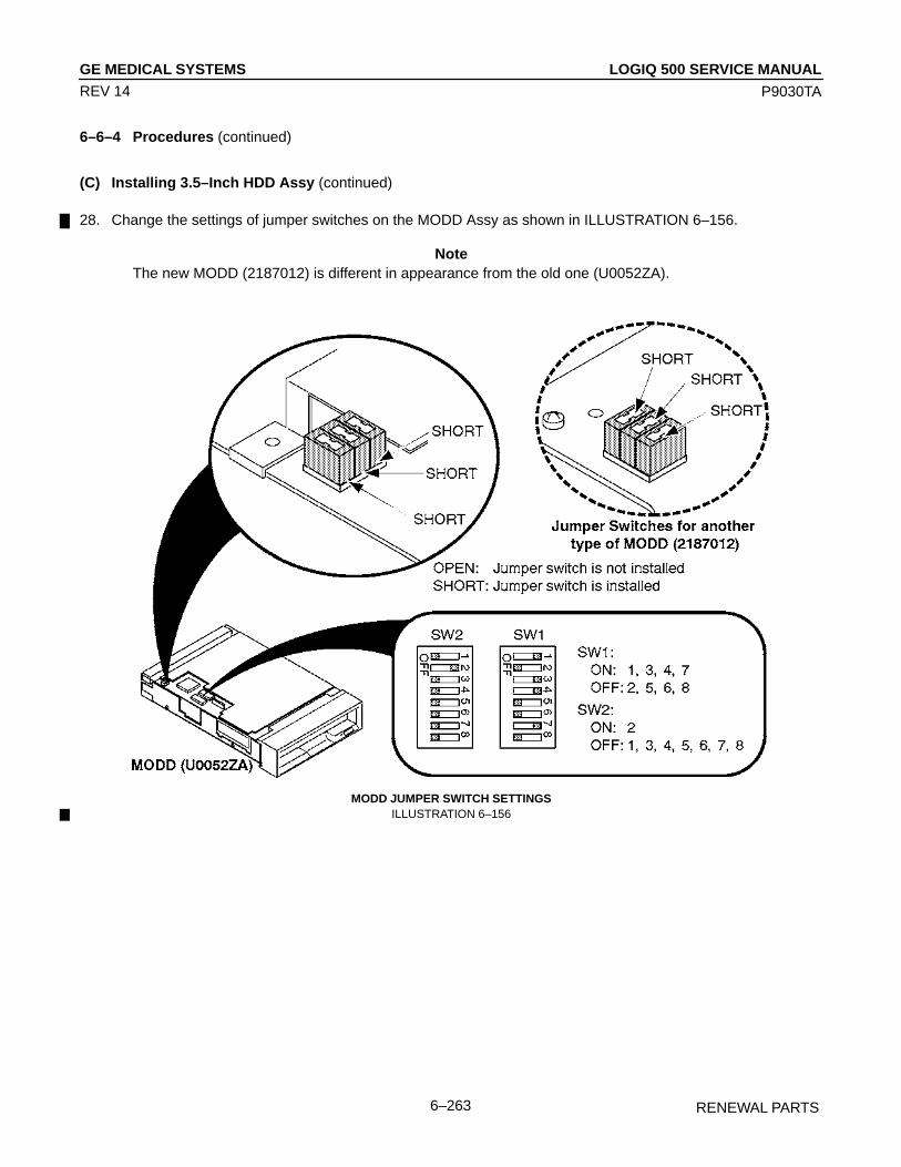
LOGIQ 500 SERVICE MANUALGE MEDICAL SYSTEMS
P9030TA
RENEWAL PARTS6–263
REV 14
6–6–4 Procedures (continued)
(C) Installing 3.5–Inch HDD Assy (continued)
28. Change the settings of jumper switches on the MODD Assy as shown in ILLUSTRATION 6–156.
NoteThe new MODD (2187012) is different in appearance from the old one (U0052ZA).
MODD JUMPER SWITCH SETTINGSILLUSTRATION 6–156

LOGIQ 500 SERVICE MANUALGE MEDICAL SYSTEMS
P9030TA
RENEWAL PARTS6–264
REV 14
6–6–4 Procedures (continued)
(C) Installing 3.5–Inch HDD Assy (continued)
NoteIf the 3.5–inch HDD is installed on the console, set the jumper switches as shown inILLUSTRATION 6–157.
SETTINGS OF JUMPER SWITCHES ON MODD (2187012–2)ILLUSTRATION 6–157
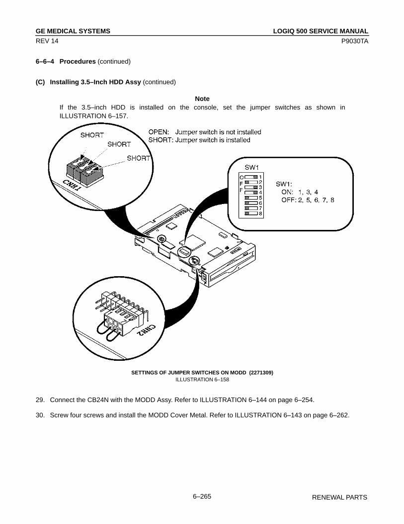
LOGIQ 500 SERVICE MANUALGE MEDICAL SYSTEMS
P9030TA
RENEWAL PARTS6–265
REV 14
6–6–4 Procedures (continued)
(C) Installing 3.5–Inch HDD Assy (continued)
NoteIf the 3.5–inch HDD is installed on the console, set the jumper switches as shown inILLUSTRATION 6–157.
SETTINGS OF JUMPER SWITCHES ON MODD (2271309)ILLUSTRATION 6–158
29. Connect the CB24N with the MODD Assy. Refer to ILLUSTRATION 6–144 on page 6–254.
30. Screw four screws and install the MODD Cover Metal. Refer to ILLUSTRATION 6–143 on page 6–262.

LOGIQ 500 SERVICE MANUALGE MEDICAL SYSTEMS
P9030TA
RENEWAL PARTS6–266
REV 14
6–6–4 Procedures (continued)
(C) Installing 3.5–Inch HDD Assy (continued)
31. Bind the CB24N cable with two tie wraps as shown in ILLUSTRATION 6–159.
NoteBe careful not to bind the CB24N tightly.
ATTACHING TIE WRAPILLUSTRATION 6–159
32. Reinstall the Side Cover Right. Refer to 6–2–21 on page 6–98.
33. Reinstall the Front Base Cover. Refer to 6–2–26 on page 6–103.
34. Reinstall the Keyboard Panel Assy. Refer to 6–2–41 on page 6–121.
35. This completes the Replacing 2.5–inch HDD Assy with 3.5–inch HDD Assy.

GE MEDICAL SYSTEMS
P9030TA
LOGIQ 500 SERVICE MANUAL
PERIODIC MAINTENANCE7–1
REV 10
CHAPTER 7 – PERIODIC MAINTENANCE
TABLE OF CONTENTS
SECTION TITLE PAGE
7–1 INTRODUCTION 7–3. . . . . . . . . . . . . . . . . . . . . . . . . . . . . . . . . . . . . . . . . . . . . . . . . . . . . . . . . . . . . . . . . . . . . 7–1–1 Periodic Maintenance 7–3. . . . . . . . . . . . . . . . . . . . . . . . . . . . . . . . . . . . . . . . . . . . . . . . . . . . . . . . .
7–2 PERIODIC MAINTENANCE PROCEDURE 7–3. . . . . . . . . . . . . . . . . . . . . . . . . . . . . . . . . . . . . . . . . . . . . . 7–2–1 Visual Inspection 7–3. . . . . . . . . . . . . . . . . . . . . . . . . . . . . . . . . . . . . . . . . . . . . . . . . . . . . . . . . . . . . 7–2–2 Cleaning 7–4. . . . . . . . . . . . . . . . . . . . . . . . . . . . . . . . . . . . . . . . . . . . . . . . . . . . . . . . . . . . . . . . . . . . 7–2–3 Measurement 7–5. . . . . . . . . . . . . . . . . . . . . . . . . . . . . . . . . . . . . . . . . . . . . . . . . . . . . . . . . . . . . . . . 7–2–4 User Data Backup 7–6. . . . . . . . . . . . . . . . . . . . . . . . . . . . . . . . . . . . . . . . . . . . . . . . . . . . . . . . . . . . 7–2–5 Note 7–6. . . . . . . . . . . . . . . . . . . . . . . . . . . . . . . . . . . . . . . . . . . . . . . . . . . . . . . . . . . . . . . . . . . . . . . .
7–3 ELECTRICAL SAFETY TESTS 7–7. . . . . . . . . . . . . . . . . . . . . . . . . . . . . . . . . . . . . . . . . . . . . . . . . . . . . . . . . 7–3–1 Outlet Test Wiring Arrangement 7–7. . . . . . . . . . . . . . . . . . . . . . . . . . . . . . . . . . . . . . . . . . . . . . . . 7–3–2 Grounding Continuity 7–8. . . . . . . . . . . . . . . . . . . . . . . . . . . . . . . . . . . . . . . . . . . . . . . . . . . . . . . . . 7–3–3 Chassis Leakage Current Test 7–9. . . . . . . . . . . . . . . . . . . . . . . . . . . . . . . . . . . . . . . . . . . . . . . . . 7–3–4 Probe Leakage Current Test 7–12. . . . . . . . . . . . . . . . . . . . . . . . . . . . . . . . . . . . . . . . . . . . . . . . . . 7–3–5 ECG Leakage Current Test 7–16. . . . . . . . . . . . . . . . . . . . . . . . . . . . . . . . . . . . . . . . . . . . . . . . . . . 7–3–6 When There’s Too Much Leakage Current 7–20. . . . . . . . . . . . . . . . . . . . . . . . . . . . . . . . . . . . . .

GE MEDICAL SYSTEMS
P9030TA
LOGIQ 500 SERVICE MANUAL
PERIODIC MAINTENANCE7–2
REV 4
This page is left blank intentionally.
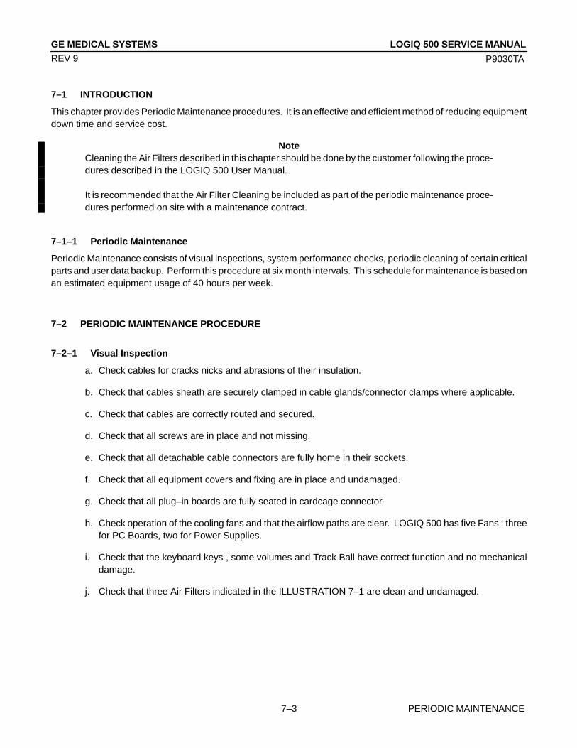
GE MEDICAL SYSTEMS
P9030TA
LOGIQ 500 SERVICE MANUAL
PERIODIC MAINTENANCE7–3
REV 9
7–1 INTRODUCTION
This chapter provides Periodic Maintenance procedures. It is an effective and efficient method of reducing equipmentdown time and service cost.
NoteCleaning the Air Filters described in this chapter should be done by the customer following the proce-dures described in the LOGIQ 500 User Manual.
It is recommended that the Air Filter Cleaning be included as part of the periodic maintenance proce-dures performed on site with a maintenance contract.
7–1–1 Periodic Maintenance
Periodic Maintenance consists of visual inspections, system performance checks, periodic cleaning of certain criticalparts and user data backup. Perform this procedure at six month intervals. This schedule for maintenance is based onan estimated equipment usage of 40 hours per week.
7–2 PERIODIC MAINTENANCE PROCEDURE
7–2–1 Visual Inspection
a. Check cables for cracks nicks and abrasions of their insulation.
b. Check that cables sheath are securely clamped in cable glands/connector clamps where applicable.
c. Check that cables are correctly routed and secured.
d. Check that all screws are in place and not missing.
e. Check that all detachable cable connectors are fully home in their sockets.
f. Check that all equipment covers and fixing are in place and undamaged.
g. Check that all plug–in boards are fully seated in cardcage connector.
h. Check operation of the cooling fans and that the airflow paths are clear. LOGIQ 500 has five Fans : threefor PC Boards, two for Power Supplies.
i. Check that the keyboard keys , some volumes and Track Ball have correct function and no mechanicaldamage.
j. Check that three Air Filters indicated in the ILLUSTRATION 7–1 are clean and undamaged.

GE MEDICAL SYSTEMS
P9030TA
LOGIQ 500 SERVICE MANUAL
PERIODIC MAINTENANCE7–4
REV 9
7–2–2 Cleaning
a. Clean the CRT filter.
a–1. Remove the CRT filter from the monitor. Refer to section 6–2–6 in Chapter 6, RENEWAL PARTS.
CAUTION
Equipment damage possibility. Do not use a hydrocarbon glass cleaner on a monitor with ananti-glare shield. Prolonged use of such cleaners damages the shield.
a–2. Wipe the monitor face and CRT filter using a soft, non-abrasive folded cloth with a glass cleaner.
a–3. Install the CRT filter after cleaning the monitor face and CRT filter. Set the CRT filter on the monitor,insert the CRT filter clamps ( 1 ), and slide them inwards securely ( 2 ).
INSTALLING CRT FILTER AND CLAMPSILLUSTRATION 7–1
NoteMake sure that the filter is securely fixed by the filter clamps. These are important to prevent a hazardfrom the filter falling. A “click” sound will be heard when the filter clamp is secured by the lock mecha-nism.
b. Clean the Fans and the Finger Guards by using a vacuum cleaner and bristled brush.
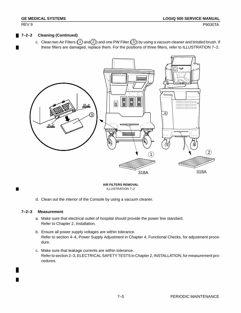
GE MEDICAL SYSTEMS
P9030TA
LOGIQ 500 SERVICE MANUAL
PERIODIC MAINTENANCE7–5
REV 9
7–2–2 Cleaning (Continued)
c. Clean two Air Filters ( 1 and 2 ) and one PW Filter ( 3 ) by using a vacuum cleaner and bristled brush. Ifthese filters are damaged, replace them. For the positions of three filters, refer to ILLUSTRATION 7–2.
ÎÎÎÎ
ÎÎ
ÎÎÎÎ ÎÎÎÎÎÎÎÎÎÎÎ
ÎÎÎÎÎÎÎÎÎÎÎÎÎÎÎÎ
Î Î
ÎÎ
ÎÎÎÎÎÎÎÎ
ÎÎÎÎÎÎÎ ÎÎ
Î
ÎÎ
ÎÎÎÎ
ÎÎÎÎ
Î
ÎÎ
ÎÎÎÎÎÎÎÎÎÎÎÎÎÎÎ
ÎÎÎÎÎÎÎ
ÎÎÎÎÎÎÎÎÎÎÎÎÎÎÎÎÎÎÎÎÎ
ÏÏÏÏÏÏÏÏÏÏÏÏÏÏ
ÎÎÎÎÎÎÎÎÎÎÎÎÎÎ
ÏÏÏÏÏÏÏÏÏÏÏÏÏÏÏÏÏÏÏÏÏ
Î
ÎÎ
ÎÎÎÎ
ÎÎÎÎ
ÎÎÎ
Î
Î
ÎÎ
ÎÎ
ÎÎÎÎÎÎÎÎ
Î
ÌÌÌÌÌÌ
318A
21
318A
AIR FILTERS REMOVALILLUSTRATION 7–2
d. Clean out the interior of the Console by using a vacuum cleaner.
7–2–3 Measurement
a. Make sure that electrical outlet of hospital should provide the power line standard.Refer to Chapter 2, Installation.
b. Ensure all power supply voltages are within tolerance.Refer to section 4–4, Power Supply Adjustment in Chapter 4, Functional Checks, for adjustment proce-dure.
c. Make sure that leakage currents are within tolerance.Refer to section 2–3, ELECTRICAL SAFETY TESTS in Chapter 2, INSTALLATION, for measurement pro-cedures.

GE MEDICAL SYSTEMS
P9030TA
LOGIQ 500 SERVICE MANUAL
PERIODIC MAINTENANCE7–6
REV 9
7–2–4 User Data Backup
a. Keep user preset data into some floppy disks or MO disk using the User Data Backup of LOGIQ 500 Utilitymenu. Refer to 4–3–3, Utility Menu in Chapter 4, FUNCTIONAL CHECKS.
7–2–5 Note
Visual inspection of probes (“head”, cable and connector)
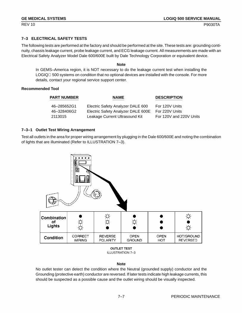
GE MEDICAL SYSTEMS
P9030TA
LOGIQ 500 SERVICE MANUAL
PERIODIC MAINTENANCE7–7
REV 10
7–3 ELECTRICAL SAFETY TESTS
The following tests are performed at the factory and should be performed at the site. These tests are: grounding conti-nuity, chassis leakage current, probe leakage current, and ECG leakage current. All measurements are made with anElectrical Safety Analyzer Model Dale 600/600E built by Dale Technology Corporation or equivalent device.
NoteIn GEMS–America region, it is NOT necessary to do the leakage current test when installing theLOGIQ 500 systems on condition that no optional devices are installed with the console. For moredetails, contact your regional service support center.
Recommended Tool
PART NUMBER NAME DESCRIPTION
46–285652G1 Electric Safety Analyzer DALE 600 For 120V Units46–328406G2 Electric Safety Analyzer DALE 600E For 220V Units2113015 Leakage Current Ultrasound Kit For 120V and 220V Units
7–3–1 Outlet Test Wiring Arrangement
Test all outlets in the area for proper wiring arrangement by plugging in the Dale 600/600E and noting the combinationof lights that are illuminated (Refer to ILLUSTRATION 7–3).
OUTLET TESTILLUSTRATION 7–3
NoteNo outlet tester can detect the condition where the Neutral (grounded supply) conductor and theGrounding (protective earth) conductor are reversed. If later tests indicate high leakage currents, thisshould be suspected as a possible cause and the outlet wiring should be visually inspected.

GE MEDICAL SYSTEMS
P9030TA
LOGIQ 500 SERVICE MANUAL
PERIODIC MAINTENANCE7–8
REV 10
7–3–2 Grounding Continuity
CAUTION
Electric Shock Hazard. The patient must not be contacted to the equipment during this test.
Measure the resistance from the third pin of the attachment plug to the exposed metal parts of the case(ILLUSTRATION 7–4). The ground wire resistance should be less than 0.2 ohms.
CONSOLE
OHMMETER
GROUND PIN
ACCESSIBLE METAL PARTS
1. Monitor Housing2. Rear Panel Connector3. Any Caster/Wheel Support
GROUND CONTINUITY TESTILLUSTRATION 7–4
Meter Procedure
Follow these steps to test the ground wire resistance.
1. Turn the LOGIQ 500 unit OFF.
2. Plug the unit into the meter, and the meter into the tested AC wall outlet (Refer to ILLUSTRATION 7–6).
3. Plug the black chassis cable into the meter’s “CHASSIS” connector and attach the black chassis cable clamp toan exposed metal part of the LOGIQ 500 unit (Refer to ILLUSTRATION 7–6).
4. Set the meter’s “FUNCTION” switch to the RESISTANCE position.
5. Set the meter’s “POLARITY” switch to the OFF (center) position.
6. Measure the ground wire resistance and keep a record of the results with other hard copies of PM data kept onsite.
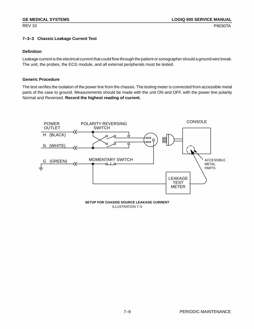
GE MEDICAL SYSTEMS
P9030TA
LOGIQ 500 SERVICE MANUAL
PERIODIC MAINTENANCE7–9
REV 10
7–3–3 Chassis Leakage Current Test
Definition
Leakage current is the electrical current that could flow through the patient or sonographer should a ground wire break.The unit, the probes, the ECG module, and all external peripherals must be tested.
Generic Procedure
The test verifies the isolation of the power line from the chassis. The testing meter is connected from accessible metalparts of the case to ground. Measurements should be made with the unit ON and OFF, with the power line polarityNormal and Reversed. Record the highest reading of current.
POWEROUTLET
H (BLACK)
POLARITY REVERSING SWITCH
MOMENTARY SWITCH
N (WHITE)
G (GREEN)
LEAKAGETEST
METER
ACCESSIBLEMETALPARTS
CONSOLE
SETUP FOR CHASSIS SOURCE LEAKAGE CURRENTILLUSTRATION 7–5
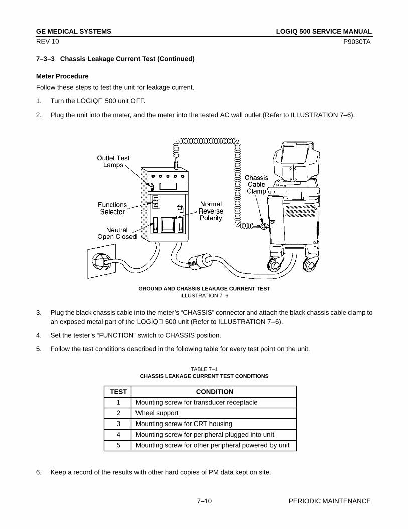
GE MEDICAL SYSTEMS
P9030TA
LOGIQ 500 SERVICE MANUAL
PERIODIC MAINTENANCE7–10
REV 10
7–3–3 Chassis Leakage Current Test (Continued)
Meter Procedure
Follow these steps to test the unit for leakage current.
1. Turn the LOGIQ 500 unit OFF.
2. Plug the unit into the meter, and the meter into the tested AC wall outlet (Refer to ILLUSTRATION 7–6).
GROUND AND CHASSIS LEAKAGE CURRENT TESTILLUSTRATION 7–6
3. Plug the black chassis cable into the meter’s “CHASSIS” connector and attach the black chassis cable clamp toan exposed metal part of the LOGIQ 500 unit (Refer to ILLUSTRATION 7–6).
4. Set the tester’s “FUNCTION” switch to CHASSIS position.
5. Follow the test conditions described in the following table for every test point on the unit.
TABLE 7–1CHASSIS LEAKAGE CURRENT TEST CONDITIONS
TEST CONDITION
1 Mounting screw for transducer receptacle
2 Wheel support
3 Mounting screw for CRT housing
4 Mounting screw for peripheral plugged into unit
5 Mounting screw for other peripheral powered by unit
6. Keep a record of the results with other hard copies of PM data kept on site.

GE MEDICAL SYSTEMS
P9030TA
LOGIQ 500 SERVICE MANUAL
PERIODIC MAINTENANCE7–11
REV 10
7–3–3 Chassis Leakage Current Test (Continued)
Data Sheet for Chassis Source Leakage Current
Follow the foregoing test procedure. The test passes when all readings measure less than the value shown in thetable below (TABLE 7–2).
TABLE 7–2MAXIMUM ALLOWANCE LIMIT FOR CHASSIS SOURCE LEAKAGE CURRENT
COUNTRY NORMAL OPEN REVERSE OPENCONDITION GROUND POLARITY NEUTRAL
USA N/A 0.3mA 0.3mA N/A
OTHERS 0.1mA 0.5mA 0.5mA 0.5mA
CAUTION
Electric Shock Hazard. When the meter’s ground switch is OPEN, don’t touch the unit!
CAUTION
Equipment damage possibility. Never switch the Polarity and the status of Neutral when theunit is powered ON. Be sure to turn the unit power OFF before switching them using the PO-LARITY switch and/or the NEUTRAL switch. Otherwise, the unit may be damaged.
TABLE 7–3DATA SHEET FOR CHASSIS SOURCE LEAKAGE CURRENT
Enter name of tested peripheral here:
ON NORM OPEN
ON NORM CLOSED
ON REV OPEN
ON REV CLOSED
OFF NORM OPEN
OFF NORM CLOSED
OFF REV OPEN
OFF REV CLOSED
Unit Tester Tester Test1 Test2 Test3 Test4 Test5Power POLARITY NEUTRAL or Probe wheel CRT
Switch GROUND connectorSwitch

GE MEDICAL SYSTEMS
P9030TA
LOGIQ 500 SERVICE MANUAL
PERIODIC MAINTENANCE7–12
REV 10
7–3–4 Probe Leakage Current Test
Definition
This test measures the current that would flow to ground from any of the probes through a patient who is being scannedand becomes grounded by touching some other grounded surface.
Generic Procedure
Measurements should be made with the ground open and closed, with power line polarity normal and reversed, andwith the unit Off and On. For each combination, the probe must be active to find the worst case condition.
POWEROUTLET
H (BLACK) POLARITY REVERSING SWITCH
MOMENTARYSWITCH
N (WHITE)
G (GREEN)LEAKAGETESTMETER
CONSOLE
PROBE
SETUP FOR PROBE LEAKAGE CURRENTILLUSTRATION 7–7
NoteEach probe will have some amount of leakage current, dependent on its design. Small variations inprobe leakage currents are normal from probe to probe. Other variations will result from differences inline voltage and test lead placement.
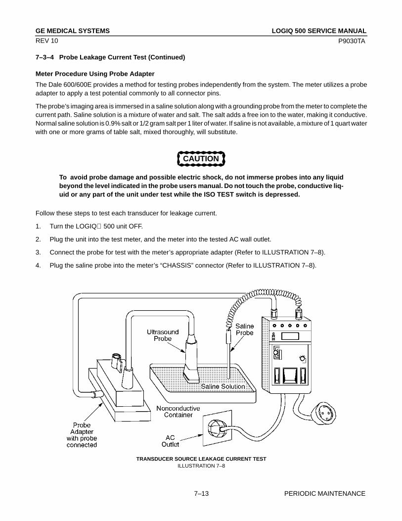
GE MEDICAL SYSTEMS
P9030TA
LOGIQ 500 SERVICE MANUAL
PERIODIC MAINTENANCE7–13
REV 10
7–3–4 Probe Leakage Current Test (Continued)
Meter Procedure Using Probe Adapter
The Dale 600/600E provides a method for testing probes independently from the system. The meter utilizes a probeadapter to apply a test potential commonly to all connector pins.
The probe’s imaging area is immersed in a saline solution along with a grounding probe from the meter to complete thecurrent path. Saline solution is a mixture of water and salt. The salt adds a free ion to the water, making it conductive.Normal saline solution is 0.9% salt or 1/2 gram salt per 1 liter of water. If saline is not available, a mixture of 1 quart waterwith one or more grams of table salt, mixed thoroughly, will substitute.
CAUTION
To avoid probe damage and possible electric shock, do not immerse probes into any liquidbeyond the level indicated in the probe users manual. Do not touch the probe, conductive liq-uid or any part of the unit under test while the ISO TEST switch is depressed.
Follow these steps to test each transducer for leakage current.
1. Turn the LOGIQ 500 unit OFF.
2. Plug the unit into the test meter, and the meter into the tested AC wall outlet.
3. Connect the probe for test with the meter’s appropriate adapter (Refer to ILLUSTRATION 7–8).
4. Plug the saline probe into the meter’s “CHASSIS” connector (Refer to ILLUSTRATION 7–8).
TRANSDUCER SOURCE LEAKAGE CURRENT TESTILLUSTRATION 7–8

GE MEDICAL SYSTEMS
P9030TA
LOGIQ 500 SERVICE MANUAL
PERIODIC MAINTENANCE7–14
REV 10
7–3–4 Probe Leakage Current Test (Continued)
5. Plug the probe adapter into the meter’s connector marked “EXTERNAL” (Refer to ILLUSTRATION 7–8).
6. Set the meter’s “FUNCTION” switch to EXTERNAL position.
7. Add the saline probe and the imaging area of the probe into the saline bath.
8. Have unit power ON for the first part; turn it OFF for the second half.
9. Depress the ISO TEST rocker switch and record the highest current reading.
10. Follow the test conditions described in the following table (TABLE 7–5) for every transducer.
11. Keep a record of the results with other hand copies of PM data.
Meter Procedure
Follow these steps to test each transducer for leakage current.
1. Turn the LOGIQ 500 unit OFF.
2. Plug the unit into the test meter, and the meter into the tested AC wall outlet.
3. Plug the external probe into the meter’s “EXTERNAL” connector.
4. Set the meter’s “FUNCTION” switch to EXTERNAL position.
5. Connect the probe for test with the connector of the console.
6. Apply a liberal amount of gel to the transducer’s lens.
7. Wrap the transducer in aluminum foil, making sure there is good contact with its acoustic aperture.
8. Either suspend the transducer by its cable or place it on an insulated surface.
9. Have unit power ON for the first part; turn it OFF for the second half.
10. Hold the external probe against the aluminum foil on the transducer when the unit is ready to scan.
11. Depress the ISO TEST rocker switch and record the highest current reading.
12. Follow the test conditions described in the following table (TABLE 7–5) for every transducer.
13. Keep a record of the results with other hand copies of PM data.
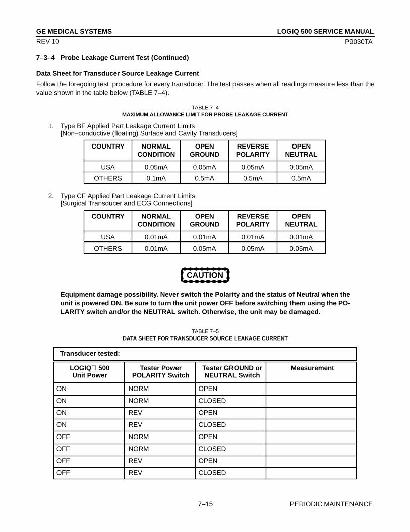
GE MEDICAL SYSTEMS
P9030TA
LOGIQ 500 SERVICE MANUAL
PERIODIC MAINTENANCE7–15
REV 10
7–3–4 Probe Leakage Current Test (Continued)
Data Sheet for Transducer Source Leakage Current
Follow the foregoing test procedure for every transducer. The test passes when all readings measure less than thevalue shown in the table below (TABLE 7–4).
TABLE 7–4MAXIMUM ALLOWANCE LIMIT FOR PROBE LEAKAGE CURRENT
COUNTRY NORMAL OPEN REVERSE OPENCONDITION GROUND POLARITY NEUTRAL
USA 0.01mA 0.01mA 0.01mA 0.01mA
OTHERS 0.01mA 0.05mA 0.05mA 0.05mA
COUNTRY NORMAL OPEN REVERSE OPENCONDITION GROUND POLARITY NEUTRAL
USA 0.05mA 0.05mA 0.05mA 0.05mA
OTHERS 0.1mA 0.5mA 0.5mA 0.5mA
1. Type BF Applied Part Leakage Current Limits[Non–conductive (floating) Surface and Cavity Transducers]
2. Type CF Applied Part Leakage Current Limits[Surgical Transducer and ECG Connections]
CAUTION
Equipment damage possibility. Never switch the Polarity and the status of Neutral when theunit is powered ON. Be sure to turn the unit power OFF before switching them using the PO-LARITY switch and/or the NEUTRAL switch. Otherwise, the unit may be damaged.
TABLE 7–5DATA SHEET FOR TRANSDUCER SOURCE LEAKAGE CURRENT
LOGIQ 500 Tester Power Tester GROUND or MeasurementUnit Power POLARITY Switch NEUTRAL Switch
ON NORM OPEN
ON NORM CLOSED
ON REV OPEN
ON REV CLOSED
OFF NORM OPEN
OFF NORM CLOSED
OFF REV OPEN
OFF REV CLOSED
Transducer tested:
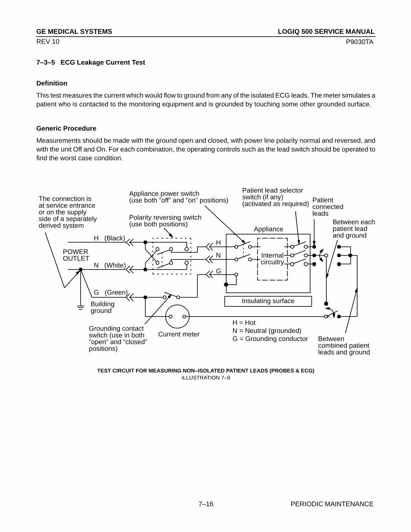
GE MEDICAL SYSTEMS
P9030TA
LOGIQ 500 SERVICE MANUAL
PERIODIC MAINTENANCE7–16
REV 10
7–3–5 ECG Leakage Current Test
Definition
This test measures the current which would flow to ground from any of the isolated ECG leads. The meter simulates apatient who is contacted to the monitoring equipment and is grounded by touching some other grounded surface.
Generic Procedure
Measurements should be made with the ground open and closed, with power line polarity normal and reversed, andwith the unit Off and On. For each combination, the operating controls such as the lead switch should be operated tofind the worst case condition.
H (Black)
N (White)
G (Green)
Internalcircuitry
Insulating surface
Polarity reversing switch(use both positions)
Appliance power switch(use both ”off” and ”on” positions) Patient
connectedleads
The connection isat service entranceor on the supplyside of a separatelyderived system
Buildingground
Grounding contactswitch (use in both”open” and ”closed”positions)
Current meter
H = HotN = Neutral (grounded)G = Grounding conductor
H
N
G
Patient lead selectorswitch (if any)(activated as required)
ApplianceBetween eachpatient leadand ground
Betweencombined patientleads and ground
POWEROUTLET
TEST CIRCUIT FOR MEASURING NON–ISOLATED PATIENT LEADS (PROBES & ECG)ILLUSTRATION 7–9
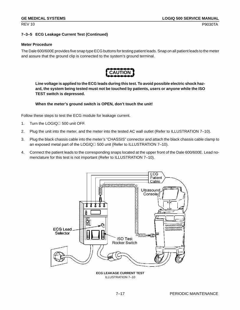
GE MEDICAL SYSTEMS
P9030TA
LOGIQ 500 SERVICE MANUAL
PERIODIC MAINTENANCE7–17
REV 10
7–3–5 ECG Leakage Current Test (Continued)
Meter Procedure
The Dale 600/600E provides five snap type ECG buttons for testing patient leads. Snap on all patient leads to the meterand assure that the ground clip is connected to the system’s ground terminal.
CAUTION
Line voltage is applied to the ECG leads during this test. To avoid possible electric shock haz-ard, the system being tested must not be touched by patients, users or anyone while the ISOTEST switch is depressed.
When the meter’s ground switch is OPEN, don’t touch the unit!
Follow these steps to test the ECG module for leakage current.
1. Turn the LOGIQ 500 unit OFF.
2. Plug the unit into the meter, and the meter into the tested AC wall outlet (Refer to ILLUSTRATION 7–10).
3. Plug the black chassis cable into the meter’s “CHASSIS” connector and attach the black chassis cable clamp toan exposed metal part of the LOGIQ 500 unit (Refer to ILLUSTRATION 7–10).
4. Connect the patient leads to the corresponding snaps located at the upper front of the Dale 600/600E. Lead no-menclature for this test is not important (Refer to ILLUSTRATION 7–10).
ECG LEAKAGE CURRENT TESTILLUSTRATION 7–10

GE MEDICAL SYSTEMS
P9030TA
LOGIQ 500 SERVICE MANUAL
PERIODIC MAINTENANCE7–18
REV 10
7–3–5 ECG Leakage Current Test (Continued)
5. Set the meter’s “FUNCTION” switch to LEAD TO GROUND position to measure the patient lead to ground leak-age current.
6. Select and test each ECG lead positions (except ALL) of the LEAD selector, testing each to the power conditioncombinations shown in TABLE 7–6.
TABLE 7–6 TESTING POWER CONDITIONS
ECG Meter’s Meter’sPower Polarity Neutral
Switch Switch
ON NORM CLOSEDON NORM OPEN
ON REVERSE CLOSED
ON REVERSE OPENOFF NORM CLOSED
OFF NORM OPEN
OFF REVERSE CLOSEDOFF REVERSE OPEN
7. Record the patient lead to ground leakage current measured on the data sheet (Refer to TABLE 7–8).
8. Set the meter’s “FUNCTION” switch to LEAD TO LEAD position to measure the lead to lead leakage current.
9. Select and test each ECG lead positions (except ALL) of the LEAD selector, testing each to the power conditioncombinations shown in TABLE 7–6.
10. Record the lead to lead leakage current measured on the data sheet (Refer to TABLE 7–8).
11. Set the meter’s “FUNCTION” switch to LEAD ISO position to measure the patient lead isolation current.
12. Select and test each ECG lead positions (except ALL) of the LEAD selector, testing each to the power conditioncombinations shown in TABLE 7–6.
13. Depress the rocker switch to ISO TEST and read the isolation current. To apply the voltage to the lead safely, thevoltage is only applied when the rocker switch is depressed to ISO TEST.
14. Record the patient lead isolation current measured on the data sheet (Refer to TABLE 7–8).
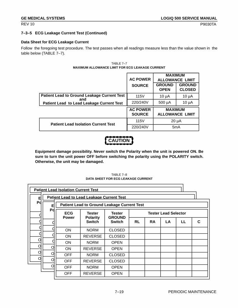
GE MEDICAL SYSTEMS
P9030TA
LOGIQ 500 SERVICE MANUAL
PERIODIC MAINTENANCE7–19
REV 10
7–3–5 ECG Leakage Current Test (Continued)
Data Sheet for ECG Leakage Current
Follow the foregoing test procedure. The test passes when all readings measure less than the value shown in thetable below (TABLE 7–7).
TABLE 7–7MAXIMUM ALLOWANCE LIMIT FOR ECG LEAKAGE CURRENT
Patient Lead to Ground Leakage Current Testand
Patient Lead to Lead Leakage Current Test
AC POWERSOURCE
115V 20 µA
220/240V 5mA
GROUND GROUNDOPEN CLOSED
115V 10 µA 10 µA
220/240V 500 µA 10 µA
MAXIMUM ALLOWANCE LIMIT
AC POWER
SOURCE
MAXIMUM ALLOWANCE LIMIT
Patient Lead Isolation Current Test
CAUTION
Equipment damage possibility. Never switch the Polarity when the unit is powered ON. Besure to turn the unit power OFF before switching the polarity using the POLARITY switch.Otherwise, the unit may be damaged.
TABLE 7–8DATA SHEET FOR ECG LEAKAGE CURRENT
ON NORM CLOSED
ON REVERSE CLOSED
ON NORM OPEN
ON REVERSE OPEN
OFF NORM CLOSED
OFF REVERSE CLOSED
OFF NORM OPEN
OFF REVERSE OPEN
ECG Tester Tester Tester Lead SelectorPower Polarity GROUND
Switch Switch RL RA LA LL C
Patient Lead Isolation Current Test
ON NORM CLOSED
ON REVERSE CLOSED
ON NORM OPEN
ON REVERSE OPEN
OFF NORM CLOSED
OFF REVERSE CLOSED
OFF NORM OPEN
OFF REVERSE OPEN
ECG Tester Tester Tester Lead SelectorPower Polarity GROUND
Switch Switch RL RA LA LL C
Patient Lead to Lead Leakage Current Test
ON NORM CLOSED
ON REVERSE CLOSED
ON NORM OPEN
ON REVERSE OPEN
OFF NORM CLOSED
OFF REVERSE CLOSED
OFF NORM OPEN
OFF REVERSE OPEN
ECG Tester Tester Tester Lead SelectorPower Polarity GROUND
Switch Switch RL RA LA LL C
Patient Lead to Ground Leakage Current Test
GE MEDICAL SYSTEMS
P9030TA
LOGIQ 500 SERVICE MANUAL
PERIODIC MAINTENANCE7–20
REV 10
7–3–6 When There’s Too Much Leakage Current...
Chassis Fails
Check the ground on the power cord and plug for continuity. Ensure the ground is not broken, frayed, or intermittent.Replace any defective part.
Tighten all grounds. Ensure star washers are under all ground studs.
Inspect wiring for bad crimps, poor connections, or damage.
Test the wall outlet; verify it is grounded. Notify the user or owner to correct any deviations. As a work around, check theother outlets to see if they could be used instead.
NoteNo outlet tester can detect the condition where the white neutral wire and the green grounding wireare reversed. If later tests indicate high leakage currents, this should be suspected as a possiblecause and the outlet wiring should be visually inspected.
Probe Fails
Test the probe in another transducer interface connector.
If excessive leakage current is slot dependent, inspect the Transducer Interface board for bent pins, poor connections,and ground continuity.
If the problem still has stayed with the probe, replace the probe.
Peripheral Fails
Tighten all grounds. Ensure star washers are under all ground studs.
Inspect wiring for bad crimps, poor connections, or damage.
Still Fails
If all else fails, begin isolation by removing the probes, external peripherals, then the on board ones, one at a time whilemonitoring the leakage current measurement.
New Unit
If the leakage current measurement tests fail on a new unit and if situation can not be corrected, submit a Safety FailureReport to document the system problem. Remove unit from operation.

GE MEDICAL SYSTEMS
P9030TA
LOGIQ 500 SERVICE MANUAL
INSTALLATION FOR OPTIONS8–1
REV 1
CHAPTER 8 – INSTALLATION FOR OPTIONS
TABLE OF CONTENTS
SECTION TITLE PAGE
8–1 INTRODUCTION 8–3. . . . . . . . . . . . . . . . . . . . . . . . . . . . . . . . . . . . . . . . . . . . . . . . . . . . . . . . . . . . . . . . . . . . .

GE MEDICAL SYSTEMS
P9030TA
LOGIQ 500 SERVICE MANUAL
INSTALLATION FOR OPTIONS8–2
REV 1
This page is left blank intentionally.

GE MEDICAL SYSTEMS
P9030TA
LOGIQ 500 SERVICE MANUAL
INSTALLATION FOR OPTIONS8–3
REV 1
8–1 INTRODUCTION
This chapter is provided to keep option installation instructions. Keep the option installation instructions on this chap-ter after completing installation for options.

GE MEDICAL SYSTEMS
P9030TA
LOGIQ 500 SERVICE MANUAL
INSTALLATION FOR OPTIONS8–4
REV 10
This page is left blank intentionally.