untitled 1
DESCRIPTION
factsTRANSCRIPT
10
INTRODUCTION
Power Generation and Transmission is a complex process, requiring the working of many
components of the power system in tandem to maximize the output. One of the main components
to form a major part is the reactive power in the system. It is required to maintain the voltage to
deliver the active power through the lines. Loads like motor loads and other loads require
reactive power for their operation. To improve the performance of ac power systems, we need to
manage this reactive power in an efficient way and this is known as reactive power
compensation. There are two aspects to the problem of reactive power compensation: load
compensation and voltage support. Load compensation consists of improvement in power factor,
balancing of real power drawn from the supply, better voltage regulation, etc. of large fluctuating
loads. Voltage support consists of reduction of voltage fluctuation at a given terminal of the
transmission line. Two types of compensation can be used: series and shunt compensation. These
modify the parameters of the system to give enhanced VAR compensation. In recent years, static
VAR compensators like the STATCOM have been developed. These quite satisfactorily do the
job of absorbing or generating reactive power with a faster time response and come under
Flexible AC Transmission Systems (FACTS). This allows an increase in transfer of apparent
power through a transmission line, and much better stability by the adjustment of parameters that
govern the power system i.e. current, voltage, phase angle, frequency and impedance.

11
CHAPTER 1
1.1 Reactive Power
Reactive power is the power that supplies the stored energy in reactive elements. Power,
as we know, consists of two components, active and reactive power. The total sum of active and
reactive power is called as apparent power.
In AC circuits, energy is stored temporarily in inductive and capacitive elements,
which results in the periodic reversal of the direction of flow of energy between the source and
the load. The average power after the completion of one whole cycle of the AC waveform is the
real power, and this is the usable energy of the system and is used to do work, whereas the
portion of power flow which is temporarily stored in the form of magnetic or electric fields and
flows back and forth in the transmission line due to inductive and capacitive network elements is
known as reactive power. This is the unused power which the system has to incur in order to
transmit power.
Inductors (reactors) are said to store or absorb reactive power, because they store energy
in the form of a magnetic field. Therefore, when a voltage is initially applied across a coil, a
magnetic field builds up, and the current reaches the full value after a certain period of time. This
in turn causes the current to lag the voltage in phase.

12
Capacitors are said to generate reactive power, because they store energy in the form of
an electric field. Therefore when current passes through the capacitor, a charge is built up to
produce the full voltage difference over a certain period of time. Thus in an AC network the
voltage across the capacitor is always charging. Since, the capacitor tends to oppose this change;
it causes the voltage to lag behind current in phase.
In an inductive circuit, we know the instantaneous power to be:
p = VmaxImax cos ωt cos(ωt − θ )
p =
( )
The instantaneous reactive power is given by:
Where:
p = instantaneous power
Vmax = Peak value of the voltage waveform
Imax = Peak value of the current waveform
ω = Angular frequency
= 2πf where f is the frequency of the waveform.
t = Time period
θ = Angle by which the current lags the voltage in phase

13
From here, we can conclude that the instantaneous reactive power pulsates at twice the
system frequency and its average value is zero and the maximum instantaneous reactive power is
given by:
Q = |V| |I| sin θ
The zero average does not necessarily mean that no energy is flowing, but the actual
amount that is flowing for half a cycle in one direction, is coming back in the next half cycle.
1.2 Compensation Techniques
The principles of both shunt and series reactive power compensation techniques
are described below:
1.2.1 Shunt compensation
Fig 1.1
14
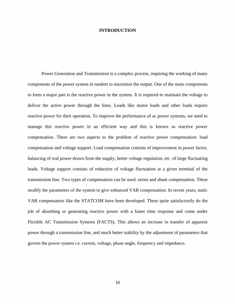
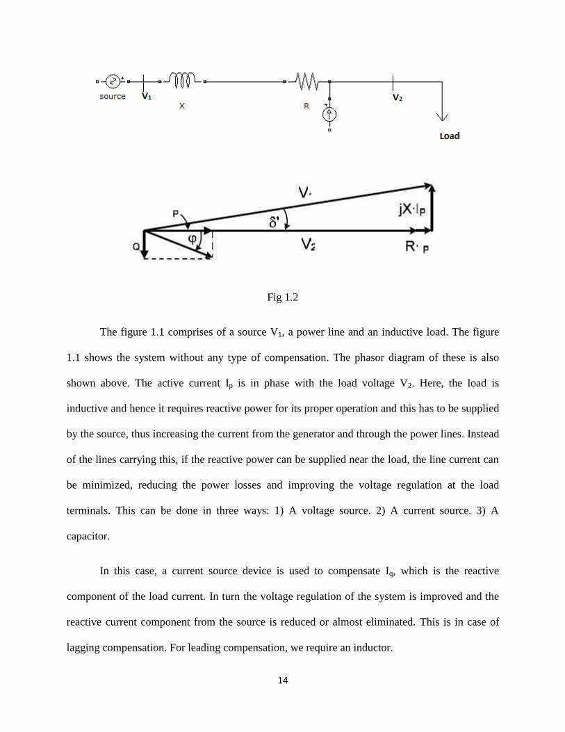
Fig 1.2
The figure 1.1 comprises of a source V1, a power line and an inductive load. The figure
1.1 shows the system without any type of compensation. The phasor diagram of these is also
shown above. The active current Ip is in phase with the load voltage V2. Here, the load is
inductive and hence it requires reactive power for its proper operation and this has to be supplied
by the source, thus increasing the current from the generator and through the power lines. Instead
of the lines carrying this, if the reactive power can be supplied near the load, the line current can
be minimized, reducing the power losses and improving the voltage regulation at the load
terminals. This can be done in three ways: 1) A voltage source. 2) A current source. 3) A
capacitor.
In this case, a current source device is used to compensate Iq, which is the reactive
component of the load current. In turn the voltage regulation of the system is improved and the
reactive current component from the source is reduced or almost eliminated. This is in case of
lagging compensation. For leading compensation, we require an inductor.

15
Therefore we can see that, a current source or a voltage source can be used for both
leading and lagging shunt compensation, the main advantages being the reactive power
generated is independent of the voltage at the point of connection. .
1.2.2 Series compensation
Fig 1.3

16
Fig 1.4
Series compensation can be implemented like shunt compensation, i.e. with a current or a
voltage source as shown in figure 1.4. We can see the results which are obtained by series
compensation through a voltage source and it is adjusted to have unity power factor at V2.
However series compensation techniques are different from shunt compensation techniques, as
capacitors are used mostly for series compensation techniques. In this case, the voltage Vcomp has
been added between the line and the load to change the angle V2’. Now, this is the voltage at the
load side. With proper adjustment of the magnitude of Vcomp, unity power factor can be reached
at V2.

17
1.3 FACTS devices used
Flexible AC transmission system or FACTS devices used are:
1) VAR generators.
a) Fixed or mechanically switched capacitors.
b) Synchronous condensers.
c) Thyristorized VAR compensators.
(i) Thyristors switched capacitors (TSCs).
(ii) Thyristor controlled reactor (TCRs).
(iii) Combined TSC and TCR.
(iv) Thyristor controlled series capacitor (TCSC).
2) Self Commutated VAR compensators.
a) Static synchronous compensators (STATCOMs).
b) Static synchronous series compensators (SSSCs).
c) Unified power flow controllers (UPFCs).
d) Dynamic voltage restorers (DVRs).
1.4 Need for Reactive power compensation.
The main reason for reactive power compensation in a system is: 1) the voltage
regulation; 2) increased system stability; 3) better utilization of machines connected to the
system; 4) reducing losses associated with the system; and 5) to prevent voltage collapse as well
as voltage sag. The impedance of transmission lines and the need for lagging VAR by most

18
machines in a generating system results in the consumption of reactive power, thus affecting the
stability limits of the system as well as transmission lines. Unnecessary voltage drops lead to
increased losses which needs to be supplied by the source and in turn leading to outages in the
line due to increased stress on the system to carry this imaginary power. Thus we can infer that
the compensation of reactive power not only mitigates all these effects but also helps in better
transient response to faults and disturbances. In recent times there has been an increased focus on
the techniques used for the compensation and with better devices included in the technology, the
compensation is made more effective. It is very much required that the lines be relieved of the
obligation to carry the reactive power, which is better provided near the generators or the loads.
Shunt compensation can be installed near the load, in a distribution substation or transmission
substation.

19
CHAPTER 2
2.1 Static Shunt Compensator: STATCOM
One of the many devices under the FACTS family, a STATCOM is a regulating device
which can be used to regulate the flow of reactive power in the system independent of other
system parameters. STATCOM has no long term energy support on the dc side and it cannot
exchange real power with the ac system. In the transmission systems, STATCOMs primarily
handle only fundamental reactive power exchange and provide voltage support to buses by
modulating bus voltages during dynamic disturbances in order to provide better transient
characteristics, improve the transient stability margins and to damp out the system oscillations
due to these disturbances.
A STATCOM consists of a three phase inverter (generally a PWM inverter) using SCRs,
MOSFETs or IGBTs, a D.C capacitor which provides the D.C voltage for the inverter, a link
reactor which links the inverter output to the a.c supply side, filter components to filter out the
high frequency components due to the PWM inverter. From the d.c. side capacitor, a three phase
voltage is generated by the inverter. This is synchronized with the a.c supply. The link inductor
links this voltage to the a.c supply side. This is the basic principle of operation of STATCOM.

20
Fig 2.1
For two AC sources which have the same frequency and are connected through a series
inductance, the active power flows from the leading source to the lagging source and the reactive
power flows from the higher voltage magnitude source to the lower voltage magnitude source.
The phase angle difference between the sources determines the active power flow and the
voltage magnitude difference between the sources determines the reactive power flow. Thus, a
STATCOM can be used to regulate the reactive power flow by changing the magnitude of the
VSC voltage with respect to source bus voltage.
2.2 Phase angle control
In this case the quantity controlled is the phase angle δ. The modulation index “m” is kept
constant and the fundamental voltage component of the STATCOM is controlled by changing
the DC link voltage. By further charging of the DC link capacitor, the DC voltage will be
increased, which in turn increases the reactive power delivered or the reactive power absorbed by
the STATCOM. On the other hand, by discharging the DC link capacitor, the reactive power
delivered is decreased in capacitive operation mode or the reactive power absorbed by the
STATCOM in an inductive power mode increases.

21
For both capacitive and inductive operations in steady-state, the STATCOM voltage lags behind
AC line voltage (δ > 0).
Fig 2.2
By making phase angle δ negative, power can be extracted from DC link. If the
STATCOM becomes lesser than the extracted power, Pc in becomes negative and STATCOM
starts to deliver active power to the source. During this transient state operation, Vd gradually
decreases.
The phasor diagrams which illustrating power flow between the DC link in transient state
and the ac supply is shown in above Fig.
For a phase angle control system, the open loop response time is determined by the DC
link capacitor and the input filter inductance. The inductance is applied to filter out converter
harmonics and by using higher values of inductance; the STATCOM current harmonics is
minimized.
The reference reactive power (Qref) is compared with the measured reactive power (Q).
The reactive power error is sent as the input to the PI controller and the output of the PI
controller determines the phase angle of the STATCOM fundamental voltage with respect to the
source voltage.

22
2.3 PWM Techniques used in STATCOM
Sinusoidal PWM technique
We use sinusoidal PWM technique to control the fundamental line to-line converter
voltage. By comparing the three sinusoidal voltage waveforms with the triangular voltage
waveform, the three phase converter voltages can be obtained.
The fundamental frequency of the converter voltage i.e. f1, modulation frequency, is
determined by the frequency of the control voltages, whereas the converter switching frequency
is determined by the frequency of the triangular voltage i.e. fs, carrier frequency. Thus, the
modulating frequency f1 is equal to the supply frequency in STATCOM.
The Amplitude modulation ratio, ma is defined as:
controla
tri
Vm
V
Where Vcontrol is the peak amplitude of the control voltage waveform and Vtri is the peak
amplitude of the triangular voltage waveform. The magnitude of triangular voltage is maintained
constant and the Vcontrol is allowed to vary.
The range of SPWM is defined for 0≤ma≤1 and over modulation is defied for ma>1.
The frequency modulation ratio mf is defined as:
sf
i
fm
f

23
The frequency modulation ratio, mf , should have odd integer values for the formation of odd and
half wave symmetric converter line-to-neutral voltage(VA0). Thus, even harmonics are
eliminated from the VA0 waveform. Also, to eliminate the harmonics we choose odd multiples of
3 for mf.
The converter output harmonic frequencies can be given as:
fh = (jmf ± k)f1
The relation between the fundamental component of the line-to-line voltage (VA0) and the
amplitude modulation ratio ma can be gives as:
0 , 12
dA a a
VV m m
From which, we can see that VA0 varies linearly with respect to ma, irrespective of mf.
The fundamental component converter line-to-line voltage can be expressed as:
1
3; 1
2 2LL a d aV m V m

24
Fig 2.3
In this type of PWM technique, we observe switching harmonics in the high frequency
range around the switching frequency and its multiples in the linear range. From above equation,
we can see that the amplitude of the fundamental component of the converter line-to-line voltage
is 0.612maVd. But for square wave operation, we know the amplitude to be 0.78Vd. Thus, in the
linear range the maximum amplitude of fundamental frequency component is reduced. This can
be solved by over modulation of the converter voltage waveform, which can increase the
harmonics in the sidebands of the converter voltage waveform. Also, the amplitude of VLL1
varies nonlinearly with ma and also varies with mf in over modulation as given

25
In a Constant DC Link Voltage Scheme the STATCOM regulates the DC link voltage
value to a fixed one in all modes of operation. This fixed value is determined by the peak
STATCOM fundamental voltage from the full inductive mode of operation to full capacitive
mode at minimum and maximum voltage supply. Therefore, for 0 ≤ ma ≤ 1;
The fundamental voltage is varied by varying ma in the linear range.