university of pune - mksss's cummins college of...
TRANSCRIPT

University of Pune
UNIVERSITY OF PUNE
Structure and Syllabus
FOR
T.E. Mechanical Engineering
2012 Course
UNDER FACULTY OF ENGINEERING
EFFECTIVE FROM June 2014
University of Pune
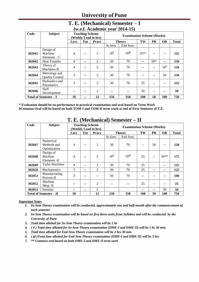
T. E. (Mechanical) Semester – I (w.e.f. Academic year 2014-15)
Code Subject Teaching Scheme
(Weekly Load in hrs) Examination Scheme (Marks)
Lect. Tut Pract. Theory TW PR OR Total
In Sem. End Sem.
302041
Design of
Machine
Elements – I
4 -- 2 30# 70
@ 25** -- -- 125
302042 Heat Transfer 4 -- 2 30 70 -- 50* -- 150
302043 Theory of
Machines-II 4 -- 2 30 70 -- -- 50
$ 150
302044 Metrology and
Quality Control 3 -- 2 30 70 -- -- 50 150
302045 Hydraulics and
Pneumatics 3 -- 2 30 70 25 -- -- 125
302046 Skill
Development -- -- 2 -- -- 50 -- -- 50
Total of Semester – I 18 -- 12 150 350 100 50 100 750
* Evaluation should be on performance in practical examination and oral based on Term Work
$Common Oral will be based on both TOM-I and TOM-II term work at end of First Semester of T.E.
T. E. (Mechanical) Semester – II Code Subject Teaching Scheme
(Weekly Load in hrs) Examination Scheme (Marks)
Lect. Tut Pract. Theory TW PR OR Total
In Sem. End Sem.
302047
Numerical
Methods and
Optimization
4 -- 2 30 70 -- 50 -- 150
302048
Design of
Machine
Elements -II
4 -- 2 30# 70
@ 25 -- 50** 175
302049 Turbo Machines 4 -- 2 30 70 25 -- 125
302050 Mechatronics 3 -- 2 30 70 25 -- -- 125
302051 Manufacturing
Process-II 3 -- -- 30 70 -- -- -- 100
302052 Machine
Shop -II -- -- 2 -- -- 25 -- -- 25
302053 Seminar -- -- 2 -- -- 50 50
Total of Semester – II 18 12 150 350 100 50 100 750
Important Notes
1. In-Sem Theory examination will be conducted, approximately one and half month after the commencement of
each semester
2. In-Sem Theory examination will be based on first three units from Syllabus and will be conducted by the
University of Pune
3. Total time allotted for In-Sem Theory examination will be 1 hr
4. ( # ) Total time allotted for In-Sem Theory examination (DME-I and DME-II) will be 1 hr 30 min.
5. Total time allotted for End-Sem Theory examination will be 2 hrs 30 min
6. ( @ )Total time allotted for End-Sem Theory examination (DME-I and DME-II) will be 3 hrs
7. ** Common oral based on both DME-I and DME-II term work

University of Pune
T.E. (Mechanical) - 2012 Course
Design of Machine Elements – I [302041]
Code Subject Teaching Scheme
(Weekly Load in hrs) Examination Scheme (Marks)
Lect. Tut Pract. Theory TW PR OR Total
In Sem. End Sem.
302041
Design of
Machine
Elements – I
4 -- 2 30
(90Min)
70
(3 hrs) 25** -- -- 125
** Common oral based on both DME-I and DME-II term work
COURSE OBJECTIVES 1. Student shall gain appreciation and understanding of the design function in Mechanical
Engineering, different steps involved in designing and the relation of design activity with
manufacturing activity.
2. The student shall learn to choose proper materials for different machine elements depending on
their physical and mechanical properties. They will learn to apply the knowledge of material
science in real life situations.
3. Student shall gain a thorough understanding of the different types of failure modes and criteria.
They will be conversant with various failure theories and be able to judge which criterion is to be
applied for a particular situation.
4. Student shall gain design knowledge of the different types of elements used in the machine design
process, for e.g. fasteners, shafts, couplings etc. and will be able to design these elements for each
application.
COURSE OUTCOMES
1. Ability to analyze the stress and strain of mechanical components and understand, identify and
quantify failure modes for mechanical part.
2. Ability to decide optimum design parameters for mechanical systems.
3. Enhancement in proficiency of CAD software for designing Mechanical systems and to generate
production drawing.
4. Ability to design mechanical system for fluctuating loads.
Unit – I Design process and design of Simple Machine elements (08 hrs)
Machine Design, Design Process, Design considerations, Standards and codes, Use of preferred series,
Factor of safety, Service factor.
Design of Cotter joint, Knuckle joint, Levers - hand / foot lever, lever for safety valve, bell crank lever,
curved beams of circular cross section and components subjected to eccentric loading.
Unit – II Design of Shafts, Keys and Couplings (08 hrs)
Shaft design on the basis of strength, torsional rigidity and lateral rigidity, A.S.M.E. code for shaft design,
Design of keys and splines. Design of Flange Coupling and Flexible Bushed Pin Coupling.
Unit – III Design for Fluctuating Load (10 hrs)
Stress concentration - causes & remedies, fluctuating stresses, fatigue failures, S-N curve, endurance
limit, notch sensitivity, endurance strength modifying factors, design for finite and infinite life,
cumulative damage in fatigue failure, Soderberg, Gerber, Goodman, Modified Goodman diagrams,
Fatigue design of components under combined stresses.
University of Pune
Unit – IV Power Screws (06 hrs)
Forms of threads, multiple start screws, Torque analysis and Design of power screws with square and
trapezoidal threads, Self locking screw, Collar friction torque, Stresses in power screws, design of a C-
Clamp. Design of screw jack, Differential and Compound Screw and Re-circulating Ball Screw
(Theoretical treatment only).
Unit –V Threaded joints and Welded joints (10 hrs)
Basic types of screw fasteners, Bolts of uniform strength, I.S.O. Metric screw threads, Bolts under
tension, Eccentrically loaded bolted joint in shear, Eccentric load perpendicular and parallel to axis of
bolt, Eccentric load on circular base. Design of Turn Buckle.
Welding symbols, Stresses in butt and fillet welds, Strength of butt, parallel and transverse fillet welds,
Axially loaded unsymmetrical welded joints, Eccentric load in plane of welds, Welded joints subjected to
bending and torsional moments.
Unit –VI Mechanical Springs (06 hrs) Types, applications and materials for springs, Stress and deflection equations for helical compression
Springs, Style of ends, Design of helical compression and tension springs, Springs in series and parallel,
Concentric helical springs. Helical torsion Spring, Surge in springs. Multi-leaf springs (Theoretical
treatment only).
Term-Work Term work shall consist of
1. Two design projects on Assemblies covering above syllabus. The design project shall consist of
two full imperial (A1) size sheet involving assembly-drawing with a part list and overall
dimensions and drawings of individual components.
Manufacturing tolerances, surface finish symbols and geometric tolerances should be specified for
important surfaces. A design report giving all necessary calculations of the design of components
and assembly should be submitted in a separate file. Design data book shall be used wherever
necessary for selection of standard components.
Drawings of design project should be done manually.
2. Assignments
The assignment shall be internally presented in the form of power point presentation, by a group of
three to five students. A report of assignment (Max 8 to 10 pages) along with print out of ppt is to
be submitted. Each student shall complete any two of the following assignments, with Assignment
(i) compulsory.
a. Selection of manufacturing methods for machine elements designed in any one of the above
design projects.
b. Selection of materials for mechanical elements.
c. Theories of failures and their applications.
d. Use of dimensional tolerances, Geometrical tolerances and surface finish symbols in machine
component drawings.
Text Books
1) Shigley J.E. and Mischke C.R., Mechanical Engineering Design, McGraw Hill Publication Co. Ltd.
2) Spotts M.F. and Shoup T.E., Design of Machine Elements, Prentice Hall International.
3) Bhandari V.B., Design of Machine Elements, Tata McGraw Hill Publication Co. Ltd.
4) Juvinal R.C., Fundamentals of Machine Components Design, John Wiley and Sons
Reference Books
1) Black P.H. and O. Eugene Adams, Machine Design, McGraw Hill Book Co. Inc.
2) Willium C. Orthwein, Machine Components Design, West Publishing Co. and Jaico Publications House.
3) Hall A.S., Holowenko A.R. and Laughlin H.G, Theory and Problems of Machine Design, Schaum‟s Outline Series.
4) C.S.Sharma and Kamlesh Purohit, Design of Machine Elements, PHI Learing Pvt. Ltd.
5) D.K.Aggarwal & P.C.Sharma, Machine Design, S.K Kataria and Sons
6) P. C. Gope, Machine Design: Fundamentals and Applications, PHI Learing Pvt. Ltd.
7) Design Data - P.S.G. College of Technology, Coimbatore.
8) Bhandari, V. B. Machine Design data book, Tata McGraw Hill Publication Co. Ltd.
9) K. Mahadevan, K. Balveera Reddy, Design Data Handbook for Mechanical Engineers, CBS Publishers.

University of Pune
T.E. (Mechanical) - 2012 Course
Heat Transfer [302042]
Code Subject Teaching Scheme
(Weekly Load in hrs) Examination Scheme (Marks)
Lect. Tut Pract. Theory TW PR OR Total
In Sem. End Sem.
302042 Heat Transfer
4 -- 2 30
(1 hr)
70 (2 hrs 30 min)
-- 50* -- 150
* Evaluation should be on performance in practical examination and oral based on Term Work and Theory
Syllabus
COURSE OBJECTIVES Heat transfer is the thermal energy in transit due to a spatial temperature difference. The topic of heat
transfer has enormous applications in mechanical engineering, ranging from cooling of microelectronics
to design of jet engines and operations of nuclear power plants. In this course,
1. Students will learn about what is heat transfer, what governs the rate of heat transfer and
importance of heat transfer.
2. They will also learn the three major modes of heat transfer viz., conduction, convection, and
radiation. In addition to these three main modes of heat transfer, students will also learn the
phenomena of heat transfer during phase change (boiling and condensation heat transfer).
3. The course provides practical exposure to the heat transfer equipments like, heat exchangers, heat
pipes, fins, etc.
COURSE OUTCOMES
1. Formulate basic equations for heat transfer problems.
2. Apply heat transfer principles to design and evaluate performance of thermal systems.
3. Calculate the effectiveness and rating of heat exchangers.
4. Calculate heat transfer by radiation between objects with simple geometries.
5. Calculate and evaluate the impact of boundary conditions on the solutions of heat transfer
problems.
6. Evaluate the relative contributions of different modes of heat transfer.
Unit – I Conduction (08 hrs)
Introduction and Basic Concepts: Application areas of heat transfer, Modes and Laws of heat transfer,
Three dimensional heat conduction equation in Cartesian coordinates and its simplified equations, thermal
conductivity, thermal diffusivity.
One dimensional steady state heat conduction without heat generation: Heat conduction in plane
wall, composite slab, composite cylinder, composite sphere, electrical analogy, concept of thermal
resistance and conductance, three dimensional heat conduction equations in cylindrical and spherical
coordinates (no derivation) and its reduction to one dimensional form, critical radius of insulation for
cylinders and spheres, economic thickness of insulation.
Unit – II Heat Generation and Transient Conduction (08 hrs)
One dimensional steady state heat conduction with heat generation: Heat conduction with uniform
heat generation in plane wall, cylinder & sphere with different boundary conditions.
Transient heat conduction: Validity and criteria of lumped system analysis, Biot and Fourier number,
Time constant and response of thermocouple, Introduction to transient heat analysis using charts.
Unit – III Boundary Conditions and Extended Surfaces (08 hrs)
Boundary and initial conditions: Temperature boundary condition, heat flux boundary condition,
convection boundary condition, radiation boundary condition.

University of Pune Heat transfer through extended surface: Types of fins, Governing Equation for constant cross sectional
area fins, solution (with derivation) for infinitely long & adequately long (with insulated end) fins and
short fins (without derivation), efficiency & effectiveness of fins.
Unit – IV Convection (10 hrs)
Fundamentals of convection: Mechanism of natural and forced convection, local and average heat
transfer coefficient, concept of velocity & thermal boundary layers.
Forced convection: Dimensionless numbers and their physical significance, empirical correlations for
external & internal flow for both laminar and turbulent flows.
Natural convection: Introduction, dimensionless numbers and their physical significance, empirical
correlations for natural convection.
Unit –V Radiation (08 hrs)
Thermal Radiation: Fundamental concepts of radiation, different laws of radiation, Radiation shape
factor, Heat exchange by radiation between two black and diffuse gray surfaces, Radiation shields.
Unit –VI Heat Exchangers and Phase Change Phenomenon (08 hrs)
Heat exchangers: Classification and applications, heat exchanger analysis – LMTD for parallel and
counter flow heat exchanger, effectiveness– NTU method for parallel and counter flow heat exchanger,
introduction to cross flow heat exchanger, LMTD correction factor, design criteria for heat exchanger,
introduction to heat pipe.
Condensation and Boiling: Boiling heat transfer, types of boiling, pool boiling curve and forced boiling
phenomenon, condensation heat transfer, film wise and drop wise condensation (No numerical treatment).
Term-Work LIST OF EXPERIMENTS
Any eight experiments (1-11) and two assignments (12-14) from the following list
1. Determination of Thermal Conductivity of metal rod
2. Determination of Thermal Conductivity of insulating powder
3. Determination of Thermal Conductivity of Composite wall
4. Determination of heat transfer coefficient in Natural Convection
5. Determination of heat transfer coefficient in Forced Convection
6. Determination of temperature distribution, fin efficiency in Natural / Forced Convection
7. Determination of Emissivity of a Test surface
8. Determination of Stefan Boltzmann Constant
9. Determination of effectiveness of heat exchanger
10. Study of pool boiling phenomenon and determination of critical heat flux
11. Determination of equivalent thermal conductivity of heat pipe
12. Assignment on 1-D transient heat transfer program using finite difference methods.
13. Assignment to solve transient heat transfer problem using Heisler and Grober charts.
14. Assignment on multi-pass / cross-flow heat exchanger using effectiveness charts.
Text Books
1. F.P. Incropera, D.P. Dewitt, Fundamentals of Heat and Mass Transfer, John Wiley.
2. Y.A. Cengel and A.J. Ghajar, Heat and Mass Transfer – Fundamentals and Applications, Tata
McGraw Hill Education Private Limited.
3. S.P. Sukhatme, A Textbook on Heat Transfer, Universities Press.
4. A.F. Mills, Basic Heat and Mass Transfer, Pearson.
Reference Books
1. S.P. Venkatesan, Heat Transfer, Ane Books Pvt. Ltd.
2. Holman, Fundamentals of Heat and Mass Transfer, McGraw – Hill publication.
3. P.K. Nag, Heat & Mass Transfer, McGraw Hill Education Private Limited.
4. M. Thirumaleshwar, Fundamentals of Heat and Mass Transfer, Pearson Education India.
5. R.C. Sachdeva, Fundamentals of Engineering Heat and Mass Transfer, New Age Science.
6. B.K. Dutta, Heat Transfer-Principles and Applictaions, PHI.
7. C.P. Kothandaraman, S.V.Subramanyam, Heat and Mass Transfer Data Book, New Academic Science.
University of Pune
T.E. (Mechanical) - 2012 Course
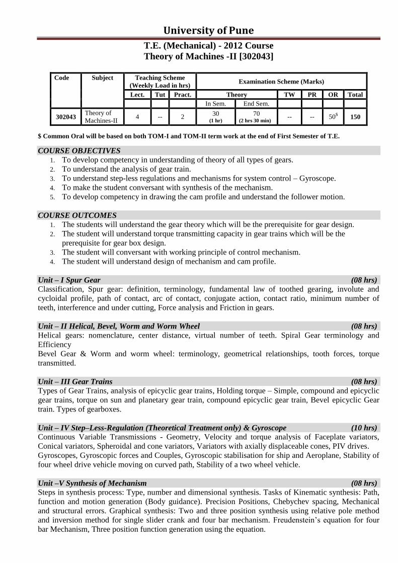
Theory of Machines -II [302043]
Code Subject Teaching Scheme
(Weekly Load in hrs) Examination Scheme (Marks)
Lect. Tut Pract. Theory TW PR OR Total
In Sem. End Sem.
302043 Theory of
Machines-II 4 -- 2
30 (1 hr)
70 (2 hrs 30 min)
-- -- 50$ 150
$ Common Oral will be based on both TOM-I and TOM-II term work at the end of First Semester of T.E.
COURSE OBJECTIVES 1. To develop competency in understanding of theory of all types of gears.
2. To understand the analysis of gear train.
3. To understand step-less regulations and mechanisms for system control – Gyroscope.
4. To make the student conversant with synthesis of the mechanism.
5. To develop competency in drawing the cam profile and understand the follower motion.
COURSE OUTCOMES
1. The students will understand the gear theory which will be the prerequisite for gear design.
2. The student will understand torque transmitting capacity in gear trains which will be the
prerequisite for gear box design.
3. The student will conversant with working principle of control mechanism.
4. The student will understand design of mechanism and cam profile.
Unit – I Spur Gear (08 hrs)
Classification, Spur gear: definition, terminology, fundamental law of toothed gearing, involute and
cycloidal profile, path of contact, arc of contact, conjugate action, contact ratio, minimum number of
teeth, interference and under cutting, Force analysis and Friction in gears.
Unit – II Helical, Bevel, Worm and Worm Wheel (08 hrs)
Helical gears: nomenclature, center distance, virtual number of teeth. Spiral Gear terminology and
Efficiency
Bevel Gear & Worm and worm wheel: terminology, geometrical relationships, tooth forces, torque
transmitted.
Unit – III Gear Trains (08 hrs)
Types of Gear Trains, analysis of epicyclic gear trains, Holding torque – Simple, compound and epicyclic
gear trains, torque on sun and planetary gear train, compound epicyclic gear train, Bevel epicyclic Gear
train. Types of gearboxes.
Unit – IV Step–Less-Regulation (Theoretical Treatment only) & Gyroscope (10 hrs)
Continuous Variable Transmissions - Geometry, Velocity and torque analysis of Faceplate variators,
Conical variators, Spheroidal and cone variators, Variators with axially displaceable cones, PIV drives.
Gyroscopes, Gyroscopic forces and Couples, Gyroscopic stabilisation for ship and Aeroplane, Stability of
four wheel drive vehicle moving on curved path, Stability of a two wheel vehicle.
Unit –V Synthesis of Mechanism (08 hrs)
Steps in synthesis process: Type, number and dimensional synthesis. Tasks of Kinematic synthesis: Path,
function and motion generation (Body guidance). Precision Positions, Chebychev spacing, Mechanical
and structural errors. Graphical synthesis: Two and three position synthesis using relative pole method
and inversion method for single slider crank and four bar mechanism. Freudenstein‟s equation for four
bar Mechanism, Three position function generation using the equation.
University of Pune
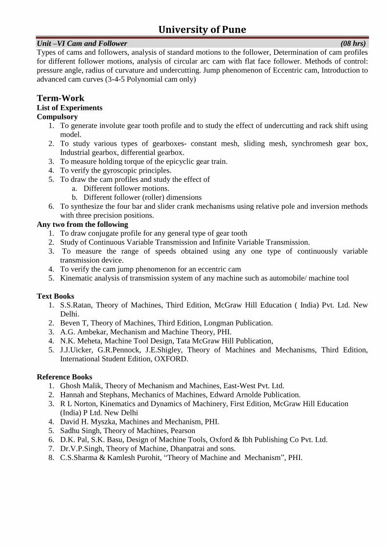
Unit –VI Cam and Follower (08 hrs)
Types of cams and followers, analysis of standard motions to the follower, Determination of cam profiles
for different follower motions, analysis of circular arc cam with flat face follower. Methods of control:
pressure angle, radius of curvature and undercutting. Jump phenomenon of Eccentric cam, Introduction to
advanced cam curves (3-4-5 Polynomial cam only)
Term-Work List of Experiments
Compulsory
1. To generate involute gear tooth profile and to study the effect of undercutting and rack shift using
model.
2. To study various types of gearboxes- constant mesh, sliding mesh, synchromesh gear box,
Industrial gearbox, differential gearbox.
3. To measure holding torque of the epicyclic gear train.
4. To verify the gyroscopic principles.
5. To draw the cam profiles and study the effect of
a. Different follower motions.
b. Different follower (roller) dimensions
6. To synthesize the four bar and slider crank mechanisms using relative pole and inversion methods
with three precision positions.
Any two from the following
1. To draw conjugate profile for any general type of gear tooth
2. Study of Continuous Variable Transmission and Infinite Variable Transmission.
3. To measure the range of speeds obtained using any one type of continuously variable
transmission device.
4. To verify the cam jump phenomenon for an eccentric cam
5. Kinematic analysis of transmission system of any machine such as automobile/ machine tool
Text Books
1. S.S.Ratan, Theory of Machines, Third Edition, McGraw Hill Education ( India) Pvt. Ltd. New
Delhi.
2. Beven T, Theory of Machines, Third Edition, Longman Publication.
3. A.G. Ambekar, Mechanism and Machine Theory, PHI.
4. N.K. Meheta, Machine Tool Design, Tata McGraw Hill Publication,
5. J.J.Uicker, G.R.Pennock, J.E.Shigley, Theory of Machines and Mechanisms, Third Edition,
International Student Edition, OXFORD.
Reference Books
1. Ghosh Malik, Theory of Mechanism and Machines, East-West Pvt. Ltd.
2. Hannah and Stephans, Mechanics of Machines, Edward Arnolde Publication.
3. R L Norton, Kinematics and Dynamics of Machinery, First Edition, McGraw Hill Education
(India) P Ltd. New Delhi
4. David H. Myszka, Machines and Mechanism, PHI.
5. Sadhu Singh, Theory of Machines, Pearson
6. D.K. Pal, S.K. Basu, Design of Machine Tools, Oxford & Ibh Publishing Co Pvt. Ltd.
7. Dr.V.P.Singh, Theory of Machine, Dhanpatrai and sons.
8. C.S.Sharma & Kamlesh Purohit, “Theory of Machine and Mechanism”, PHI.
University of Pune
T.E. (Mechanical) - 2012 Course
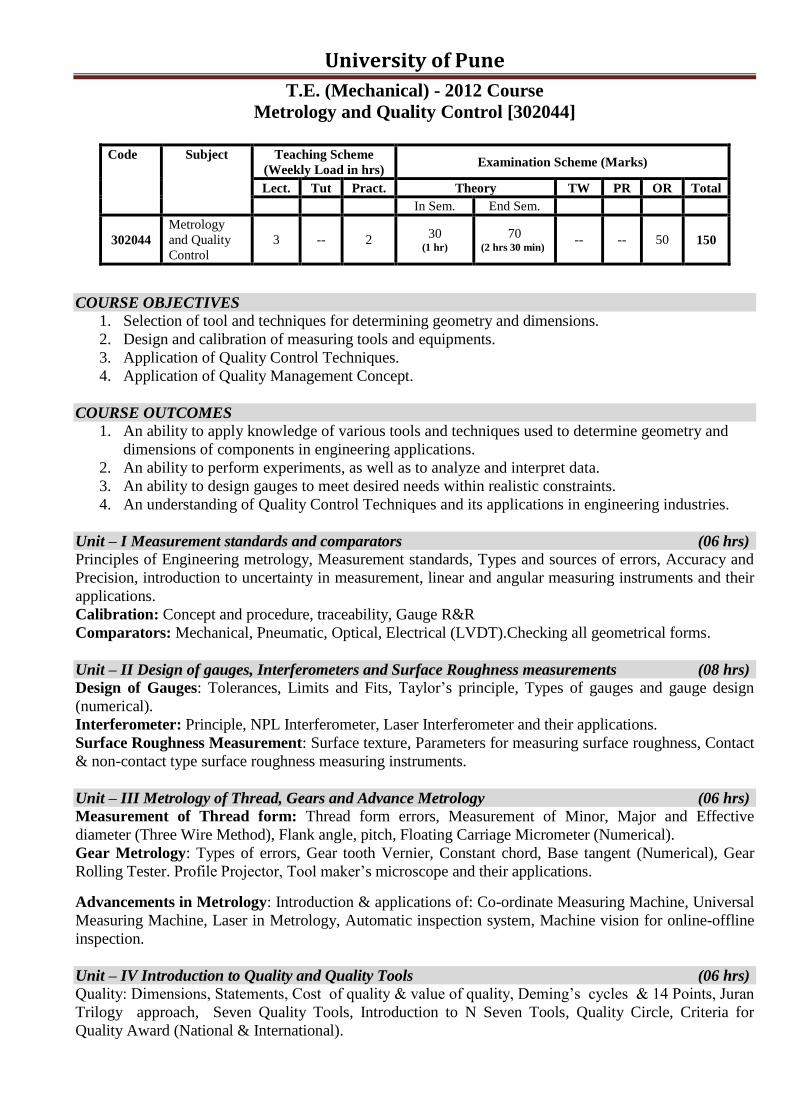
Metrology and Quality Control [302044]
Code Subject Teaching Scheme
(Weekly Load in hrs) Examination Scheme (Marks)
Lect. Tut Pract. Theory TW PR OR Total
In Sem. End Sem.
302044
Metrology
and Quality
Control
3 -- 2 30
(1 hr)
70 (2 hrs 30 min)
-- -- 50 150
COURSE OBJECTIVES 1. Selection of tool and techniques for determining geometry and dimensions.
2. Design and calibration of measuring tools and equipments.
3. Application of Quality Control Techniques.
4. Application of Quality Management Concept.
COURSE OUTCOMES
1. An ability to apply knowledge of various tools and techniques used to determine geometry and
dimensions of components in engineering applications.
2. An ability to perform experiments, as well as to analyze and interpret data.
3. An ability to design gauges to meet desired needs within realistic constraints.
4. An understanding of Quality Control Techniques and its applications in engineering industries.
Unit – I Measurement standards and comparators (06 hrs)
Principles of Engineering metrology, Measurement standards, Types and sources of errors, Accuracy and
Precision, introduction to uncertainty in measurement, linear and angular measuring instruments and their
applications.
Calibration: Concept and procedure, traceability, Gauge R&R
Comparators: Mechanical, Pneumatic, Optical, Electrical (LVDT).Checking all geometrical forms.
Unit – II Design of gauges, Interferometers and Surface Roughness measurements (08 hrs)
Design of Gauges: Tolerances, Limits and Fits, Taylor‟s principle, Types of gauges and gauge design
(numerical).
Interferometer: Principle, NPL Interferometer, Laser Interferometer and their applications.
Surface Roughness Measurement: Surface texture, Parameters for measuring surface roughness, Contact
& non-contact type surface roughness measuring instruments.
Unit – III Metrology of Thread, Gears and Advance Metrology (06 hrs)
Measurement of Thread form: Thread form errors, Measurement of Minor, Major and Effective
diameter (Three Wire Method), Flank angle, pitch, Floating Carriage Micrometer (Numerical).
Gear Metrology: Types of errors, Gear tooth Vernier, Constant chord, Base tangent (Numerical), Gear
Rolling Tester. Profile Projector, Tool maker‟s microscope and their applications.
Advancements in Metrology: Introduction & applications of: Co-ordinate Measuring Machine, Universal
Measuring Machine, Laser in Metrology, Automatic inspection system, Machine vision for online-offline
inspection.
Unit – IV Introduction to Quality and Quality Tools (06 hrs)
Quality: Dimensions, Statements, Cost of quality & value of quality, Deming‟s cycles & 14 Points, Juran
Trilogy approach, Seven Quality Tools, Introduction to N Seven Tools, Quality Circle, Criteria for
Quality Award (National & International).
University of Pune
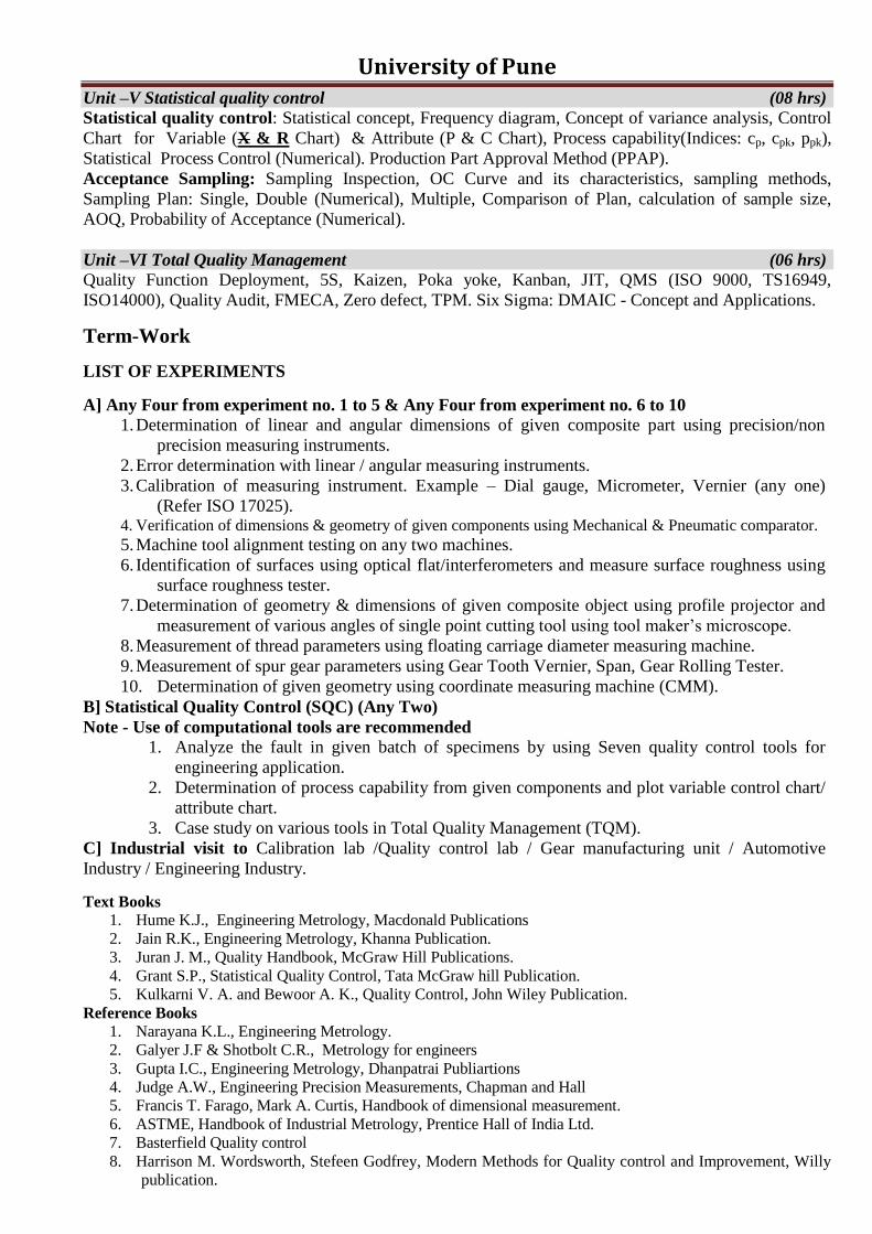
Unit –V Statistical quality control (08 hrs)
Statistical quality control: Statistical concept, Frequency diagram, Concept of variance analysis, Control
Chart for Variable (X & R Chart) & Attribute (P & C Chart), Process capability(Indices: cp, cpk, ppk),
Statistical Process Control (Numerical). Production Part Approval Method (PPAP).
Acceptance Sampling: Sampling Inspection, OC Curve and its characteristics, sampling methods,
Sampling Plan: Single, Double (Numerical), Multiple, Comparison of Plan, calculation of sample size,
AOQ, Probability of Acceptance (Numerical).
Unit –VI Total Quality Management (06 hrs)
Quality Function Deployment, 5S, Kaizen, Poka yoke, Kanban, JIT, QMS (ISO 9000, TS16949,
ISO14000), Quality Audit, FMECA, Zero defect, TPM. Six Sigma: DMAIC - Concept and Applications.
Term-Work
LIST OF EXPERIMENTS
A] Any Four from experiment no. 1 to 5 & Any Four from experiment no. 6 to 10
1. Determination of linear and angular dimensions of given composite part using precision/non
precision measuring instruments.
2. Error determination with linear / angular measuring instruments.
3. Calibration of measuring instrument. Example – Dial gauge, Micrometer, Vernier (any one)
(Refer ISO 17025). 4. Verification of dimensions & geometry of given components using Mechanical & Pneumatic comparator.
5. Machine tool alignment testing on any two machines.
6. Identification of surfaces using optical flat/interferometers and measure surface roughness using
surface roughness tester.
7. Determination of geometry & dimensions of given composite object using profile projector and
measurement of various angles of single point cutting tool using tool maker‟s microscope.
8. Measurement of thread parameters using floating carriage diameter measuring machine.
9. Measurement of spur gear parameters using Gear Tooth Vernier, Span, Gear Rolling Tester.
10. Determination of given geometry using coordinate measuring machine (CMM).
B] Statistical Quality Control (SQC) (Any Two)
Note - Use of computational tools are recommended
1. Analyze the fault in given batch of specimens by using Seven quality control tools for
engineering application.
2. Determination of process capability from given components and plot variable control chart/
attribute chart.
3. Case study on various tools in Total Quality Management (TQM).
C] Industrial visit to Calibration lab /Quality control lab / Gear manufacturing unit / Automotive
Industry / Engineering Industry.
Text Books
1. Hume K.J., Engineering Metrology, Macdonald Publications
2. Jain R.K., Engineering Metrology, Khanna Publication.
3. Juran J. M., Quality Handbook, McGraw Hill Publications.
4. Grant S.P., Statistical Quality Control, Tata McGraw hill Publication.
5. Kulkarni V. A. and Bewoor A. K., Quality Control, John Wiley Publication.
Reference Books
1. Narayana K.L., Engineering Metrology.
2. Galyer J.F & Shotbolt C.R., Metrology for engineers
3. Gupta I.C., Engineering Metrology, Dhanpatrai Publiartions
4. Judge A.W., Engineering Precision Measurements, Chapman and Hall
5. Francis T. Farago, Mark A. Curtis, Handbook of dimensional measurement.
6. ASTME, Handbook of Industrial Metrology, Prentice Hall of India Ltd.
7. Basterfield Quality control
8. Harrison M. Wordsworth, Stefeen Godfrey, Modern Methods for Quality control and Improvement, Willy
publication.
University of Pune
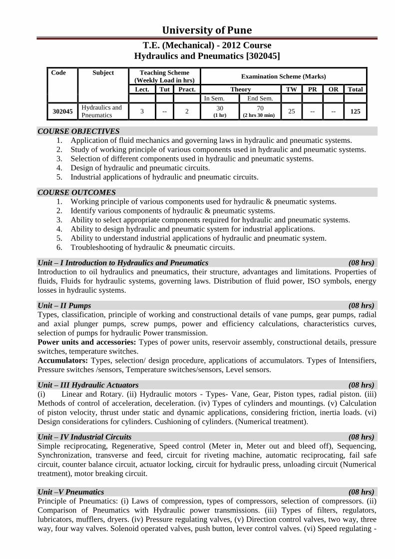
T.E. (Mechanical) - 2012 Course
Hydraulics and Pneumatics [302045]
Code Subject Teaching Scheme
(Weekly Load in hrs) Examination Scheme (Marks)
Lect. Tut Pract. Theory TW PR OR Total
In Sem. End Sem.
302045 Hydraulics and
Pneumatics 3 -- 2
30 (1 hr)
70 (2 hrs 30 min)
25 -- -- 125
COURSE OBJECTIVES 1. Application of fluid mechanics and governing laws in hydraulic and pneumatic systems.
2. Study of working principle of various components used in hydraulic and pneumatic systems.
3. Selection of different components used in hydraulic and pneumatic systems.
4. Design of hydraulic and pneumatic circuits.
5. Industrial applications of hydraulic and pneumatic circuits.
COURSE OUTCOMES
1. Working principle of various components used for hydraulic & pneumatic systems.
2. Identify various components of hydraulic & pneumatic systems.
3. Ability to select appropriate components required for hydraulic and pneumatic systems.
4. Ability to design hydraulic and pneumatic system for industrial applications.
5. Ability to understand industrial applications of hydraulic and pneumatic system.
6. Troubleshooting of hydraulic & pneumatic circuits.
Unit – I Introduction to Hydraulics and Pneumatics (08 hrs)
Introduction to oil hydraulics and pneumatics, their structure, advantages and limitations. Properties of
fluids, Fluids for hydraulic systems, governing laws. Distribution of fluid power, ISO symbols, energy
losses in hydraulic systems.
Unit – II Pumps (08 hrs)
Types, classification, principle of working and constructional details of vane pumps, gear pumps, radial
and axial plunger pumps, screw pumps, power and efficiency calculations, characteristics curves,
selection of pumps for hydraulic Power transmission.
Power units and accessories: Types of power units, reservoir assembly, constructional details, pressure
switches, temperature switches.
Accumulators: Types, selection/ design procedure, applications of accumulators. Types of Intensifiers,
Pressure switches /sensors, Temperature switches/sensors, Level sensors.
Unit – III Hydraulic Actuators (08 hrs)
(i) Linear and Rotary. (ii) Hydraulic motors - Types- Vane, Gear, Piston types, radial piston. (iii)
Methods of control of acceleration, deceleration. (iv) Types of cylinders and mountings. (v) Calculation
of piston velocity, thrust under static and dynamic applications, considering friction, inertia loads. (vi)
Design considerations for cylinders. Cushioning of cylinders. (Numerical treatment).
Unit – IV Industrial Circuits (08 hrs)
Simple reciprocating, Regenerative, Speed control (Meter in, Meter out and bleed off), Sequencing,
Synchronization, transverse and feed, circuit for riveting machine, automatic reciprocating, fail safe
circuit, counter balance circuit, actuator locking, circuit for hydraulic press, unloading circuit (Numerical
treatment), motor breaking circuit.
Unit –V Pneumatics (08 hrs)
Principle of Pneumatics: (i) Laws of compression, types of compressors, selection of compressors. (ii)
Comparison of Pneumatics with Hydraulic power transmissions. (iii) Types of filters, regulators,
lubricators, mufflers, dryers. (iv) Pressure regulating valves, (v) Direction control valves, two way, three
way, four way valves. Solenoid operated valves, push button, lever control valves. (vi) Speed regulating -

University of Pune Methods used in Pneumatics. (vii) Pneumatic actuators-rotary, reciprocating.(viii) Air motors- radial
piston, vane, axial piston (ix) Basic pneumatic circuit, selection of components, (x) Application of
pneumatics in low cost automation and in industrial automation.
Introduction to vacuum and vacuum measurement, Vacuum pumps, types, introduction to vacuum sensors
and valves. Industrial application of vacuum.
Unit –VI System Design (08 hrs)
Design of hydraulic/pneumatic circuit for practical application, Selection of different components such as
reservoir, various valves, actuators, filters, pumps based on design. (Students are advised to refer
manufacturers catalogues)
Term-Work
Minimum of 8 experiments and 2 assignments from the following; out of which serial no. 1 to 3 and 10
are compulsory, one from serial no 4 and 5 , three from serial no. 6 to 9 (For Design of system use any
software like Automation Studio) and minimum 2 assignments from serial no. 11 to 14. Record of
experiments, industrial visit and assignments shall be submitted in the form of journal.
1. Test on Gear/Vane/Piston pump and plotting of performance characteristics
2. Following experiments to be done on hydraulic trainer:
a. Regenerative circuit b. Speed control circuit
c. Sequencing circuit d. Transverse and feed circuit
3. Following experiments to be done on pneumatic trainer:
a. Automatic reciprocating circuit b. Speed control circuit
c. Pneumatic circuit involving shuttle valve/ quick exhaust valve
d. Electro pneumatic valves and circuit
4. Test on pressure relief valve
5. Test on liner/rotary actuator
6. Design of accumulators and intensifiers in hydraulic system
7. Design of air distribution in pneumatic system
8. Design of simple hydraulic systems used in practice such as copy turning attachment, hydraulic
clamps, jack, dumper, forklift etc.
9. Design of simple pneumatic systems used in practice such as braking system, vibrator, drilling, chisel etc.
10. Industrial visit to study automation by means of hydraulic and pneumatic system such as LPG
bottling plant, hydraulic press, Injection moulding machines etc.
11. Assignment on ISO symbols for different components of Hydraulic and Pneumatic system
12. Assignment on different types of actuators used in Pneumatic and Hydraulic system
13. Assignment on trouble shooting procedures of various hydraulic and pneumatic systems
14. Assignment on selection of circuit components for simple hydraulic and pneumatic systems
Text books 1. Esposito, Fluid Power with application, Prentice Hall
2. Majumdar S.R, Oil Hydraulic system- Principle and maintenance ,Tata McGraw Hill
3. Majumdar S.R ,Pneumatics Systems Principles and Maintenance ,Tata McGraw Hill
4. H.L.Stewart, Hydraulics and Pneumatics , Taraporewala Publication
Reference books
1. J. J. Pipenger, Industrial Hydraulics, McGraw Hill
2. Pinches, Industrial Fluid Power, Prentice Hall
3. D. A. Pease, Basic Fluid Power, Prentice Hall
4. B. Lall, Oil Hydraulics, International Literature Association
5. Yeaple, Fluid Power Design Handbook
6. Andrew A. Parr, Hydraulics and Pneumatics, Elsevier Science and Technology Books.
7. ISO - 1219, Fluid Systems and components, Graphic Symbols
8. Michael J, Prinches and Ashby J. G, “Power Hydraulics”, Prentice Hall.
9. Dr. R.K. Bansal, Fluid Mechanics, Laxmi Publication (P) Ltd.
10. Product Manuals and books from Vickers/ Eaton, FESTO, SMC pneumatics
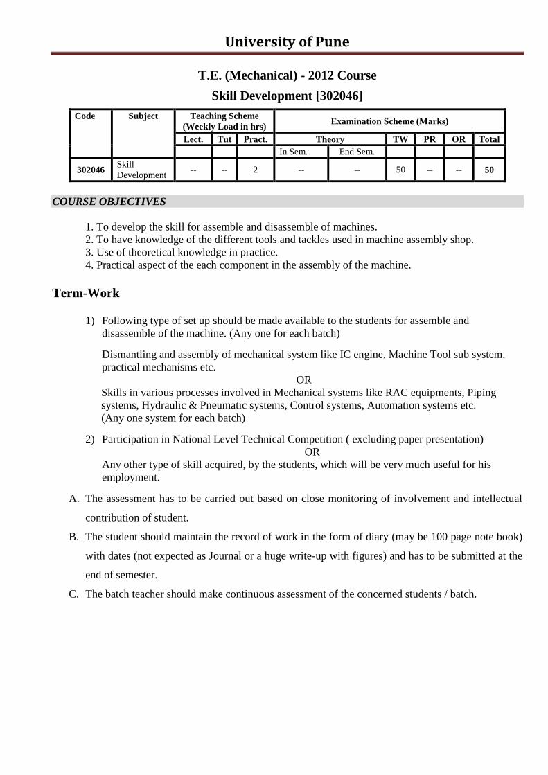
University of Pune
T.E. (Mechanical) - 2012 Course
Skill Development [302046]
Code Subject Teaching Scheme
(Weekly Load in hrs) Examination Scheme (Marks)
Lect. Tut Pract. Theory TW PR OR Total
In Sem. End Sem.
302046 Skill
Development -- -- 2 -- -- 50 -- -- 50
COURSE OBJECTIVES
1. To develop the skill for assemble and disassemble of machines.
2. To have knowledge of the different tools and tackles used in machine assembly shop.
3. Use of theoretical knowledge in practice.
4. Practical aspect of the each component in the assembly of the machine.
Term-Work
1) Following type of set up should be made available to the students for assemble and
disassemble of the machine. (Any one for each batch)
Dismantling and assembly of mechanical system like IC engine, Machine Tool sub system,
practical mechanisms etc.
OR
Skills in various processes involved in Mechanical systems like RAC equipments, Piping
systems, Hydraulic & Pneumatic systems, Control systems, Automation systems etc.
(Any one system for each batch)
2) Participation in National Level Technical Competition ( excluding paper presentation)
OR
Any other type of skill acquired, by the students, which will be very much useful for his
employment.
A. The assessment has to be carried out based on close monitoring of involvement and intellectual
contribution of student.
B. The student should maintain the record of work in the form of diary (may be 100 page note book)
with dates (not expected as Journal or a huge write-up with figures) and has to be submitted at the
end of semester.
C. The batch teacher should make continuous assessment of the concerned students / batch.
University of Pune
T.E. (Mechanical) - 2012 Course
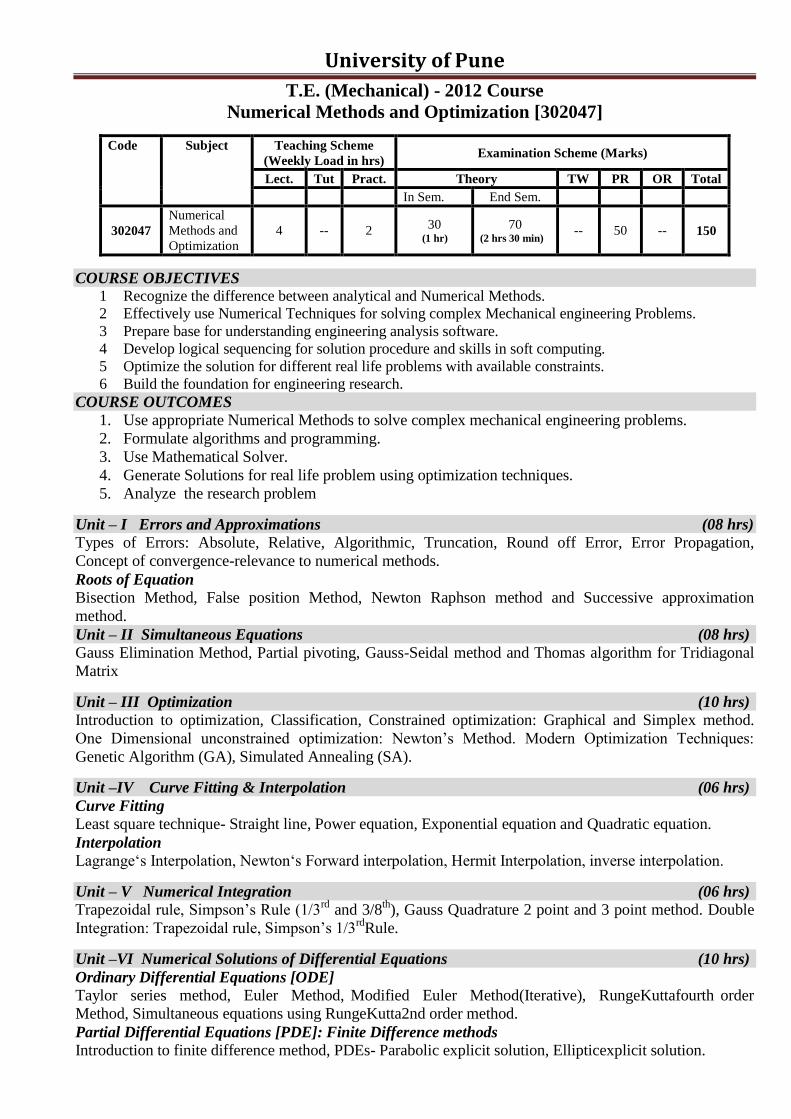
Numerical Methods and Optimization [302047]
Code Subject Teaching Scheme
(Weekly Load in hrs) Examination Scheme (Marks)
Lect. Tut Pract. Theory TW PR OR Total
In Sem. End Sem.
302047
Numerical
Methods and
Optimization
4 -- 2 30
(1 hr)
70 (2 hrs 30 min)
-- 50 -- 150
COURSE OBJECTIVES 1 Recognize the difference between analytical and Numerical Methods.
2 Effectively use Numerical Techniques for solving complex Mechanical engineering Problems.
3 Prepare base for understanding engineering analysis software.
4 Develop logical sequencing for solution procedure and skills in soft computing.
5 Optimize the solution for different real life problems with available constraints.
6 Build the foundation for engineering research.
COURSE OUTCOMES
1. Use appropriate Numerical Methods to solve complex mechanical engineering problems.
2. Formulate algorithms and programming.
3. Use Mathematical Solver.
4. Generate Solutions for real life problem using optimization techniques.
5. Analyze the research problem
Unit – I Errors and Approximations (08 hrs)
Types of Errors: Absolute, Relative, Algorithmic, Truncation, Round off Error, Error Propagation,
Concept of convergence-relevance to numerical methods.
Roots of Equation
Bisection Method, False position Method, Newton Raphson method and Successive approximation
method.
Unit – II Simultaneous Equations (08 hrs)
Gauss Elimination Method, Partial pivoting, Gauss-Seidal method and Thomas algorithm for Tridiagonal
Matrix
Unit – III Optimization (10 hrs)
Introduction to optimization, Classification, Constrained optimization: Graphical and Simplex method.
One Dimensional unconstrained optimization: Newton‟s Method. Modern Optimization Techniques:
Genetic Algorithm (GA), Simulated Annealing (SA).
Unit –IV Curve Fitting & Interpolation (06 hrs)
Curve Fitting Least square technique- Straight line, Power equation, Exponential equation and Quadratic equation.
Interpolation
Lagrange„s Interpolation, Newton„s Forward interpolation, Hermit Interpolation, inverse interpolation.
Unit – V Numerical Integration (06 hrs)
Trapezoidal rule, Simpson‟s Rule (1/3rd
and 3/8th
), Gauss Quadrature 2 point and 3 point method. Double
Integration: Trapezoidal rule, Simpson‟s 1/3rd
Rule.
Unit –VI Numerical Solutions of Differential Equations (10 hrs)
Ordinary Differential Equations [ODE]
Taylor series method, Euler Method, Modified Euler Method(Iterative), RungeKuttafourth order
Method, Simultaneous equations using RungeKutta2nd order method.
Partial Differential Equations [PDE]: Finite Difference methods
Introduction to finite difference method, PDEs- Parabolic explicit solution, Ellipticexplicit solution.

University of Pune
Term-Work
1. Program on Roots of Equation (Validation by suitable solver, all four compulsory)
a). Bisection Method, b. False position Method,
c). Newton Raphson method d. Successive approximation method
2. Program on Simultaneous Equations (Validation by suitable solver, all three compulsory)
a) Gauss Elimination Method,
b) Thomas algorithm for tridiagonal matrix,
c) Gauss-Seidal method.
3. Program on Numerical Integration(Validation by suitable solver, all four compulsory)
a) Trapezoidal rule,
b) Simpson‟s Rules (1/3rd
, 3/8th
) [In one program only]
c) Gauss Quadrature Method- 2 point, 3 point. [In one program only]
d) Double integration: Trapezoidal rule, Simpson‟s 1/3rd
Rule.
4. Program on Curve Fitting using Least square technique (Validation by suitable solver, all four
compulsory)
a) Straight line,
b) Power equation
c) Exponential equation
d) Quadratic equation
5. Program on Interpolation(Validation by suitable solver, all three compulsory)
a) Lagrange„s Interpolation,
b) Newton„s Forward interpolation,
c) Inverse interpolation
6. Program on ODE(Validation by suitable solver, all three compulsory)
a) Euler Method(Iterative),
b) Runge-Kutta Methods- fourth order,
c) Simultaneous equations.(Runge-Kutta 2nd order: One step only).
7. Program on PDE(Validation by suitable solver)
8. Theory assignment on Modern Optimization techniques.
GUIDELINES TO CONDUCT PRACTICAL EXAMINATION
Any one program from each set A & B with flowchart and solver: Duration: 2 hrs.
Set A: (Weightage – 60 %)
a). Simultaneous Equation. b). Partial Differential Equation c). Interpolation.
Set B: (Weightage – 40 %)
a). Roots of Equations. b). Curve Fitting. c). Ordinary Differential Equations. d). Integration
Text Books 1. Steven C. Chapra, Raymond P. Canale, Numerical Methods for Engineers, 4/e, Tata McGraw Hill Editions
2. Dr. B. S. Garewal, Numerical Methods in Engineering and Science, Khanna Publishers,.
3. Steven C. Chapra, Applied Numerical Methods with MATLAB for Engineers and Scientist, Tata
Mc-GrawHill Publishing Co-Ltd
4. Rao V. Dukkipati, Applied Numerical Methods using Matlab, New Age International Publishers
Reference Books
1. Gerald and Wheatley, Applied Numerical Analysis, Pearson Education Asia
2. E. Balagurusamy, Numerical Methods, Tata McGraw Hill
3. P. Thangaraj, Computer Oriented Numerical Methods, PHI
4. S. S. Sastry, Introductory Methods of Numerical Analysis, PHI.

University of Pune
T.E. (Mechanical) - 2012 Course
Design of Machine Elements – II [302048]
Code Subject Teaching Scheme
(Weekly Load in hrs) Examination Scheme (Marks)
Lect. Tut Pract. Theory TW PR OR Total
In Sem. End Sem.
302048
Design of
Machine
Elements –II
4 -- 2 30
(90Min)
70
(3 hrs) 25 -- 50** 175
** Common oral based on both DME-I and DME-II term work
COURSE OBJECTIVES
1. Reinforce the philosophy that real engineering design problems are open-ended
2. Give practice in longer open-ended problems using design methodology
3. Enable students to apply engineering tools/techniques to product design
4. Broaden skills in team work, critical thinking, communication, planning and scheduling through
design projects
5. Enable students to consider safety, ethical, legal, and other societal constraints in execution of
their design projects
6. Enable students to attain the basic knowledge required to understand, analyze, design and select
machine elements
COURSE OUTCOMES
1. Ability to design and analyze Mechanical transmission systems
2. Ability to design and select different types of bearings from manufacturer‟s catalogue.
3. Enhancement in proficiency of CAD software for design and analysis so that students are capable
to generate production drawing.
Unit –I Spur Gears (08 hrs)
Gear Drives: Classification of gears, Selection of types of gears, Selection of materials for gears,
Standard systems of gear tooth, Basic modes of gear tooth failures, Gear Lubrication Methods.
Spur Gears: Number of teeth and face width, Types of gear tooth failure, Desirable properties and
selection of gear material, Constructional details of gear wheel, Force analysis (Theoretical Treatment
only), Beam strength (Lewis) equation, Velocity factor, Service factor, Load concentration factor,
Effective load on gear, Wear strength (Buckingham‟s) equation, Estimation of module based on beam and
wear strength, Estimation of dynamic tooth load by velocity factor and Buckingham‟s equation.
Unit – II Helical and Bevel Gears (08 hrs)
Helical Gears: Transverse and normal module, Virtual no of teeth, Force analysis (Theoretical Treatment
only), Beam and wear strengths, Effective load on gear tooth, Estimation of dynamic load by velocity
factor and Buckingham‟s equation, Design of helical gears.
Bevel Gears: Straight tooth bevel gear terminology and geometric relationship, Formative number of
teeth, Force analysis (Theoretical Treatment only), Design criteria of bevel gears, Beam and wear
strengths, Dynamic tooth load by Velocity factor and Buckingham‟s equation, Effective load, Design of
straight tooth bevel gears.
Unit – III Rolling Contact Bearings (08 hrs)
Types of rolling contact Bearings, Static and dynamic load carrying capacities, Stribeck‟sEquation,
Equivalent bearing load, Load-life relationship, Selection of bearing life Selection of rolling contact
bearings from manufacturer‟s catalogue, Design for cyclic loads and speed, bearing with probability of
survival other than 90%
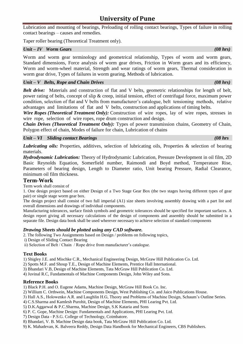
University of Pune Lubrication and mounting of bearings, Preloading of rolling contact bearings, Types of failure in rolling
contact bearings – causes and remedies.
Taper roller bearing (Theoretical Treatment only).
Unit – IV Worm Gears (08 hrs)
Worm and worm gear terminology and geometrical relationship, Types of worm and worm gears,
Standard dimensions, Force analysis of worm gear drives, Friction in Worm gears and its efficiency,
Worm and worm-wheel material, Strength and wear ratings of worm gears, Thermal consideration in
worm gear drive, Types of failures in worm gearing, Methods of lubrication.
Unit – V Belts, Rope and Chain Drives (08 hrs)
Belt drive: Materials and construction of flat and V belts, geometric relationships for length of belt,
power rating of belts, concept of slip & creep, initial tension, effect of centrifugal force, maximum power
condition, selection of flat and V belts from manufacturer‟s catalogue, belt tensioning methods, relative
advantages and limitations of flat and V belts, construction and applications of timing belts.
Wire Ropes (Theoretical Treatment Only): Construction of wire ropes, lay of wire ropes, stresses in
wire rope, selection of wire ropes, rope drum construction and design.
Chain Drives (Theoretical Treatment Only): Types of power transmission chains, Geometry of Chain,
Polygon effect of chain, Modes of failure for chain, Lubrication of chains
Unit – VI Sliding contact Bearings (08 hrs
Lubricating oils: Properties, additives, selection of lubricating oils, Properties & selection of bearing
materials.
Hydrodynamic Lubrication: Theory of Hydrodynamic Lubrication, Pressure Development in oil film, 2D
Basic Reynolds Equation, Somerfield number, Raimondi and Boyd method, Temperature Rise,
Parameters of bearing design, Length to Diameter ratio, Unit bearing Pressure, Radial Clearance,
minimum oil film thickness.
Term-Work Term work shall consist of
1. One design project based on either Design of a Two Stage Gear Box (the two stages having different types of gear
pair) or single stage worm gear box.
The design project shall consist of two full imperial (A1) size sheets involving assembly drawing with a part list and
overall dimensions and drawings of individual components.
Manufacturing tolerances, surface finish symbols and geometric tolerances should be specified for important surfaces. A
design report giving all necessary calculations of the design of components and assembly should be submitted in a
separate file. Design data book shall be used wherever necessary to achieve selection of standard components
Drawing Sheets should be plotted using any CAD software. 2. The following Two Assignments based on Design / problems on following topics,
i) Design of Sliding Contact Bearing
ii) Selection of Belt / Chain / Rope drive from manufacturer‟s catalogue.
Text Books 1) Shigley J.E. and Mischke C.R., Mechanical Engineering Design, McGraw Hill Publication Co. Ltd.
2) Spotts M.F. and Shoup T.E., Design of Machine Elements, Prentice Hall International.
3) Bhandari V.B, Design of Machine Elements, Tata McGraw Hill Publication Co. Ltd.
4) Juvinal R.C, Fundamentals of Machine Components Design, John Wiley and Sons.
Reference Books 1) Black P.H. and O. Eugene Adams, Machine Design, McGraw Hill Book Co. Inc.
2) Willium C. Orthwein, Machine Components Design, West Publishing Co. and Jaico Publications House.
3) Hall A.S., Holowenko A.R. and Laughlin H.G, Theory and Problems of Machine Design, Schaum‟s Outline Series. 4) C.S.Sharma and Kamlesh Purohit, Design of Machine Elements, PHI Learing Pvt. Ltd.
5) D.K.Aggarwal & P.C.Sharma, Machine Design, S.K Kataria and Sons
6) P. C. Gope, Machine Design: Fundamentals and Applications, PHI Learing Pvt. Ltd.
7) Design Data - P.S.G. College of Technology, Coimbatore.
8) Bhandari, V. B. Machine Design data book, Tata McGraw Hill Publication Co. Ltd.
9) K. Mahadevan, K. Balveera Reddy, Design Data Handbook for Mechanical Engineers, CBS Publishers.
University of Pune
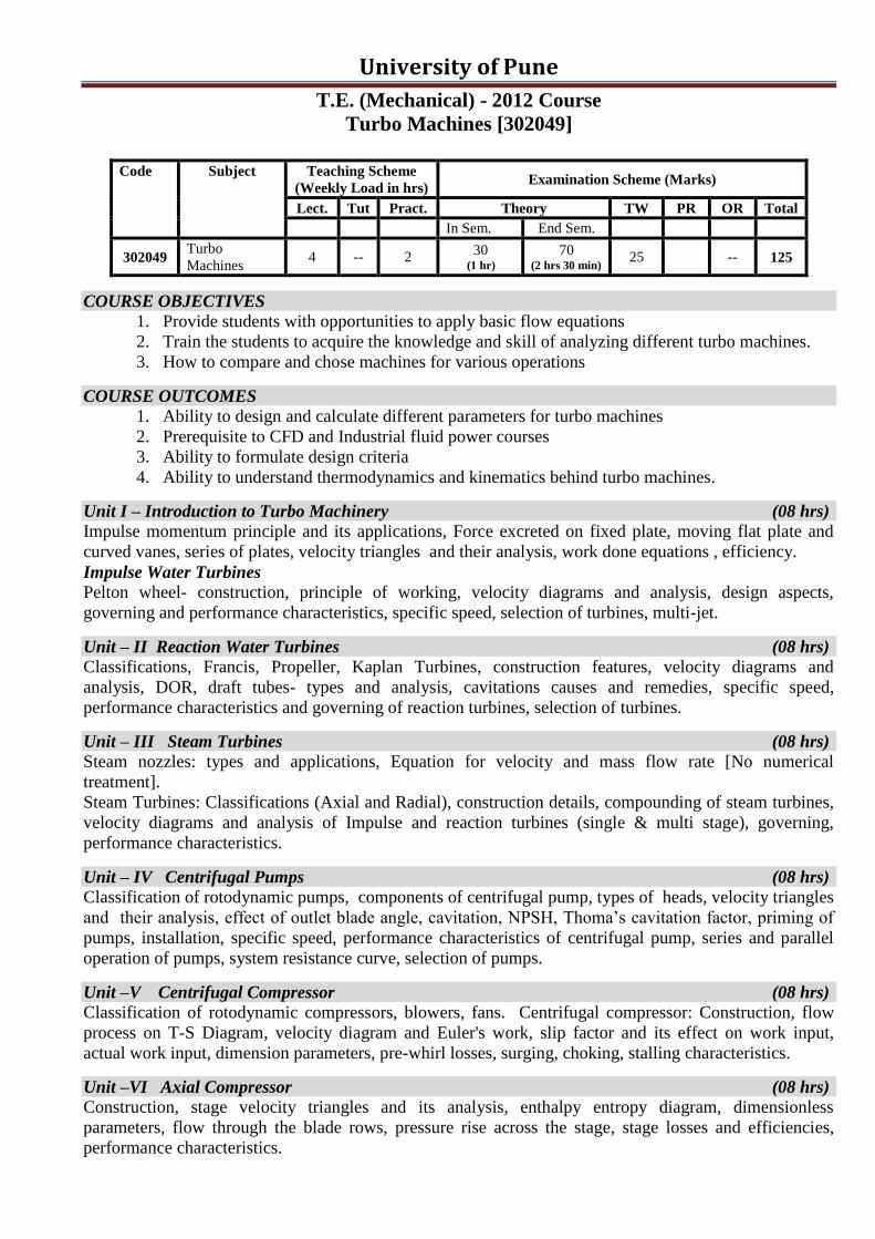
T.E. (Mechanical) - 2012 Course
Turbo Machines [302049]
Code Subject Teaching Scheme
(Weekly Load in hrs) Examination Scheme (Marks)
Lect. Tut Pract. Theory TW PR OR Total
In Sem. End Sem.
302049 Turbo
Machines 4 -- 2
30 (1 hr)
70 (2 hrs 30 min)
25 -- 125
COURSE OBJECTIVES 1. Provide students with opportunities to apply basic flow equations
2. Train the students to acquire the knowledge and skill of analyzing different turbo machines.
3. How to compare and chose machines for various operations
COURSE OUTCOMES
1. Ability to design and calculate different parameters for turbo machines
2. Prerequisite to CFD and Industrial fluid power courses
3. Ability to formulate design criteria
4. Ability to understand thermodynamics and kinematics behind turbo machines.
Unit I – Introduction to Turbo Machinery (08 hrs)
Impulse momentum principle and its applications, Force excreted on fixed plate, moving flat plate and
curved vanes, series of plates, velocity triangles and their analysis, work done equations , efficiency.
Impulse Water Turbines
Pelton wheel- construction, principle of working, velocity diagrams and analysis, design aspects,
governing and performance characteristics, specific speed, selection of turbines, multi-jet.
Unit – II Reaction Water Turbines (08 hrs)
Classifications, Francis, Propeller, Kaplan Turbines, construction features, velocity diagrams and
analysis, DOR, draft tubes- types and analysis, cavitations causes and remedies, specific speed,
performance characteristics and governing of reaction turbines, selection of turbines.
Unit – III Steam Turbines (08 hrs)
Steam nozzles: types and applications, Equation for velocity and mass flow rate [No numerical
treatment].
Steam Turbines: Classifications (Axial and Radial), construction details, compounding of steam turbines,
velocity diagrams and analysis of Impulse and reaction turbines (single & multi stage), governing,
performance characteristics.
Unit – IV Centrifugal Pumps (08 hrs)
Classification of rotodynamic pumps, components of centrifugal pump, types of heads, velocity triangles
and their analysis, effect of outlet blade angle, cavitation, NPSH, Thoma‟s cavitation factor, priming of
pumps, installation, specific speed, performance characteristics of centrifugal pump, series and parallel
operation of pumps, system resistance curve, selection of pumps.
Unit –V Centrifugal Compressor (08 hrs)
Classification of rotodynamic compressors, blowers, fans. Centrifugal compressor: Construction, flow
process on T-S Diagram, velocity diagram and Euler's work, slip factor and its effect on work input,
actual work input, dimension parameters, pre-whirl losses, surging, choking, stalling characteristics.
Unit –VI Axial Compressor (08 hrs)
Construction, stage velocity triangles and its analysis, enthalpy entropy diagram, dimensionless
parameters, flow through the blade rows, pressure rise across the stage, stage losses and efficiencies,
performance characteristics.
University of Pune
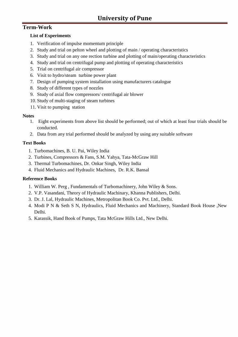
Term-Work
List of Experiments
1. Verification of impulse momentum principle
2. Study and trial on pelton wheel and plotting of main / operating characteristics
3. Study and trial on any one rection turbine and plotting of main/operating characteristics
4. Study and trial on centrifugal pump and plotting of operating characteristics
5. Trial on centrifugal air compressor
6. Visit to hydro/steam turbine power plant
7. Design of pumping system installation using manufacturers catalogue
8. Study of different types of nozzles
9. Study of axial flow compressors/ centrifugal air blower
10. Study of multi-staging of steam turbines
11. Visit to pumping station
Notes
1. Eight experiments from above list should be performed; out of which at least four trials should be
conducted.
2. Data from any trial performed should be analyzed by using any suitable software
Text Books
1. Turbomachines, B. U. Pai, Wiley India
2. Turbines, Compressors & Fans, S.M. Yahya, Tata-McGraw Hill
3. Thermal Turbomachines, Dr. Onkar Singh, Wiley India
4. Fluid Mechanics and Hydraulic Machines, Dr. R.K. Bansal
Reference Books
1. William W. Perg , Fundamentals of Turbomachinery, John Wiley & Sons.
2. V.P. Vasandani, Theory of Hydraulic Machinary, Khanna Publishers, Delhi.
3. Dr. J. Lal, Hydraulic Machines, Metropolitan Book Co. Pvt. Ltd., Delhi.
4. Modi P N & Seth S N, Hydraulics, Fluid Mechanics and Machinery, Standard Book House ,New
Delhi.
5. Karassik, Hand Book of Pumps, Tata McGraw Hills Ltd., New Delhi.
University of Pune
T.E. (Mechanical) - 2012 Course
Mechatronics [302050]
Code Subject Teaching Scheme
(Weekly Load in hrs) Examination Scheme (Marks)
Lect. Tut Pract. Theory TW PR OR Total
In Sem. End Sem.
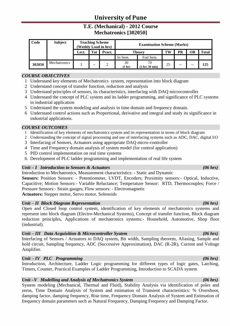
302050 Mechatronics
3 -- 2 30
(1 hr)
70 (2 hrs 30 min)
25 -- -- 125
COURSE OBJECTIVES 1 Understand key elements of Mechatronics system, representation into block diagram
2 Understand concept of transfer function, reduction and analysis
3 Understand principles of sensors, its characteristics, interfacing with DAQ microcontroller
4 Understand the concept of PLC system and its ladder programming, and significance of PLC systems
in industrial application
5 Understand the system modeling and analysis in time domain and frequency domain.
6 Understand control actions such as Proportional, derivative and integral and study its significance in
industrial applications.
COURSE OUTCOMES 1 Identification of key elements of mechatronics system and its representation in terms of block diagram
2 Understanding the concept of signal processing and use of interfacing systems such as ADC, DAC, digital I/O
3 Interfacing of Sensors, Actuators using appropriate DAQ micro-controller
4 Time and Frequency domain analysis of system model (for control application)
5 PID control implementation on real time systems
6. Development of PLC ladder programming and implementation of real life system
Unit – I Introduction to Sensors & Actuators (06 hrs)
Introduction to Mechatronics, Measurement characteristics: - Static and Dynamic
Sensors: Position Sensors: - Potentiometer, LVDT, Encoders; Proximity sensors:- Optical, Inductive,
Capacitive; Motion Sensors:- Variable Reluctance; Temperature Sensor: RTD, Thermocouples; Force /
Pressure Sensors:- Strain gauges; Flow sensors: - Electromagnetic
Actuators: Stepper motor, Servo motor, Solenoids
Unit – II Block Diagram Representation (06 hrs)
Open and Closed loop control system, identification of key elements of mechatronics systems and
represent into block diagram (Electro-Mechanical Systems), Concept of transfer function, Block diagram
reduction principles, Applications of mechatronics systems:- Household, Automotive, Shop floor
(industrial).
Unit – III Data Acquisition & Microcontroller System (06 hrs)
Interfacing of Sensors / Actuators to DAQ system, Bit width, Sampling theorem, Aliasing, Sample and
hold circuit, Sampling frequency, ADC (Successive Approximation), DAC (R-2R), Current and Voltage
Amplifier.
Unit – IV PLC Programming (06 hrs)
Introduction, Architecture, Ladder Logic programming for different types of logic gates, Latching,
Timers, Counter, Practical Examples of Ladder Programming, Introduction to SCADA system
Unit –V Modelling and Analysis of Mechatronics System (06 hrs)
System modeling (Mechanical, Thermal and Fluid), Stability Analysis via identification of poles and
zeros, Time Domain Analysis of System and estimation of Transient characteristics: % Overshoot,
damping factor, damping frequency, Rise time, Frequency Domain Analysis of System and Estimation of
frequency domain parameters such as Natural Frequency, Damping Frequency and Damping Factor.

University of Pune
Unit –VI Control System (06 hrs)
P, I and D control actions, P, PI, PD and PID control systems, Transient response:- Percentage
overshoot, Rise time, Delay time, Steady state error, PID tuning (manual).
Term-Work Lab Work (Compulsory Experiments 4, 5, 9 and any 6 out of remaining)
1 Measurement of Load / Force using Load Cell*(Estimation of unknown weight using above
voltage characteristics)
2 Measurement of Temperature : Thermocouple, Thermistor & RTD and comparative analysis
(estimation of sensitivity)
3 Measurement of displacement using LVDT characteristics.
4 Interfacing of any Sensor with Data Acquisition System
5 PLC control system: - ladder logic implementation on real time system.
6 Ladder Diagram development for different types of Logic Gates using suitable Software
7 Real Time Temperature / Flow Control using PID Control system.
8 PID control Design, Tuning using suitable Simulation Software
9 PID Control Implementation on DC Motor Speed Control System
10 Demonstration of Bottle Filling System using PLC / Microcontroller / Relays System
11 Study of Modeling and Analysis of a typical Mechanical System (Estimation of poles, zeros, %
overshoot, natural frequency, damping frequency, rise time, settling time)
Text Books
1. K.P. Ramchandran, G.K. Vijyaraghavan, M.S. Balasundaram, Mechatronics: Integrated
Mechanical Electronic Systems, Willey Publication, 2008
2. Bolton, Mechatronics - A Multidisciplinary approach, 4th
Edition, Prentice Hall, 2009.
Reference Books
1. Alciatore &Histand, Introduction to Mechatronics and Measurement system, 4th
Edition, Mc-
Graw Hill publication, 2011.
2. Bishop (Editor), Mechatronics – An Introduction, CRC Press, 2006.
3. Mahalik, Mechatronics – Principles, concepts and applications, Tata Mc-Graw Hill publication,
New Delhi.
4. C. D. Johnson, Process Control Instrumentation Technology, Prentice Hall, New Delhi.
University of Pune
T.E. (Mechanical) - 2012 Course
Manufacturing Process-II [302051] Code Subject Teaching Scheme
(Weekly Load in hrs) Examination Scheme (Marks)
Lect. Tut Pract. Theory TW PR OR Total
In Sem. End Sem.
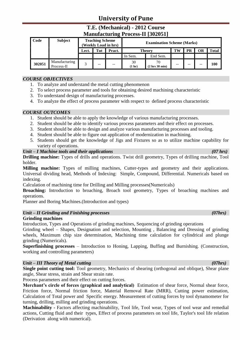
302051 Manufacturing
Process-II 3 -- --
30 (1 hr)
70 (2 hrs 30 min)
-- -- -- 100
COURSE OBJECTIVES
1. To analyze and understand the metal cutting phenomenon
2. To select process parameter and tools for obtaining desired machining characteristic
3. To understand design of manufacturing processes.
4. To analyze the effect of process parameter with respect to defined process characteristic
COURSE OUTCOMES
1. Student should be able to apply the knowledge of various manufacturing processes.
2. Student should be able to identify various process parameters and their effect on processes.
3. Student should be able to design and analyze various manufacturing processes and tooling.
4. Student should be able to figure out application of modernization in machining.
5. Students should get the knowledge of Jigs and Fixtures so as to utilize machine capability for
variety of operations.
Unit – I Machine tools and their applications (07 hrs)
Drilling machine: Types of drills and operations. Twist drill geometry, Types of drilling machine, Tool
holder.
Milling machine: Types of milling machines, Cutter-types and geometry and their applications.
Universal dividing head, Methods of Indexing: Simple, Compound, Differential. Numericals based on
indexing.
Calculation of machining time for Drilling and Milling processes(Numericals)
Broaching: Introduction to broaching, Broach tool geometry, Types of broaching machines and
operations.
Planner and Boring Machines.(Introduction and types)
Unit – II Grinding and Finishing processes (07hrs)
Grinding machines Introduction, Types and Operations of grinding machines, Sequencing of grinding operations
Grinding wheel – Shapes, Designation and selection, Mounting , Balancing and Dressing of grinding
wheels, Maximum chip size determination, Machining time calculation for cylindrical and plunge
grinding (Numericals).
Superfinishing processes – Introduction to Honing, Lapping, Buffing and Burnishing. (Construction,
working and controlling parameters)
Unit – III Theory of Metal cutting (07hrs)
Single point cutting tool: Tool geometry, Mechanics of shearing (orthogonal and oblique), Shear plane
angle, Shear stress, strain and Shear strain rate.
Process parameters and their effect on cutting forces.
Merchant’s circle of forces (graphical and analytical) Estimation of shear force, Normal shear force,
Friction force, Normal friction force, Material Removal Rate (MRR), Cutting power estimation,
Calculation of Total power and Specific energy. Measurement of cutting forces by tool dynamometer for
turning, drilling, milling and grinding operations.
Machinability - Factors affecting machinability, Tool life, Tool wear, Types of tool wear and remedial
actions, Cutting fluid and their types, Effect of process parameters on tool life, Taylor's tool life relation
(Derivation along with numerical).
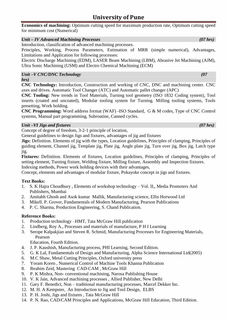
University of Pune Economics of machining: Optimum cutting speed for maximum production rate, Optimum cutting speed
for minimum cost (Numerical)
Unit – IV Advanced Machining Processes (07 hrs)
Introduction, classification of advanced machining processes.
Principles, Working, Process Parameters, Estimation of MRR (simple numerical), Advantages,
Limitations and Application for following processes:
Electric Discharge Machining (EDM), LASER Beam Machining (LBM), Abrasive Jet Machining (AJM),
Ultra Sonic Machining (USM) and Electro Chemical Machining (ECM)
Unit –V CNC/DNC Technology (07
hrs)
CNC Technology: Introduction, Construction and working of CNC, DNC and machining center. CNC
axes and drives. Automatic Tool Changer (ATC) and Automatic pallet changer (APC)
CNC Tooling: New trends in Tool Materials, Turning tool geometry (ISO 1832 Coding system), Tool
inserts (coated and uncoated), Modular tooling system for Turning. Milling tooling systems, Tools
presetting, Work holding.
CNC Programming: Word address format (WAF) -ISO Standard, G & M codes, Type of CNC Control
systems, Manual part programming, Subroutine, Canned cycles.
Unit –VI Jigs and fixtures (07 hrs) Concept of degree of freedom, 3-2-1 principle of location,
General guidelines to design Jigs and fixtures, advantages of jig and fixtures
Jigs: Definition. Elements of jig with the types, Location guidelines, Principles of clamping, Principles of
guiding element, Channel jig, Template jig, Plate jig, Angle plate jig, Turn over jig, Box jig, Latch type
jig.
Fixtures: Definition. Elements of fixtures, Location guidelines, Principles of clamping, Principles of
setting element, Turning fixture, Welding fixture, Milling fixture, Assembly and Inspection fixtures.
Indexing methods, Power work holding devices with their advantages,
Concept, elements and advantages of modular fixture, Pokayoke concept in jigs and fixtures.
Text Books:
1. S. K Hajra Choudhury , Elements of workshop technology – Vol. II,, Media Promoters And
Publishers, Mumbai
2. Amitabh Ghosh and Asok kumar Mallik, Manufacturing science, Ellis Horwood Ltd
3. Mikell. P. Grover, Fundamentals of Modern Manufacturing, Pearson Publications
4. P. C. Sharma, Production Engineering, S. Chand Publication.
Reference Books:
1. Production technology –HMT, Tata McGraw Hill publication
2. Lindberg, Roy A., Processes and materials of manufacture, P H I Learning
3. Serope Kalpakjian and Steven R. Schmid, Manufacturing Processes for Engineering Materials,
Pearson
Education, Fourth Edition.
4. J. P. Kaushish, Manufacturing process, PHI Learning, Second Edition.
5. G. K Lal, Fundamentals of Design and Manufacturing, Alpha Science International Ltd(2005)
6. M.C Shaw, Metal Cutting Principles, Oxford university press
7. Yoram Koren , Numerical Control of Machine Tools Khanna Publication
8. Ibrahim Zeid, Mastering CAD-CAM , McGraw Hill
9. P. K Mishra, Non- conventional machining, Narosa Publishing House
10. V. K Jain, Advanced machining processes , Allied Publisher, New Delhi
11. Gary F. Benedict, Non – traditional manufacturing processes, Marcel Dekker Inc.
12. M. H. A Kempster, An Introduction to Jig and Tool Design, ELBS
13. P. H. Joshi, Jigs and fixtures , Tata McGraw Hill
14. P. N. Rao, CAD/CAM Principles and Applications, McGraw Hill Education, Third Edition.
University of Pune
T.E. (Mechanical) - 2012 Course
Machine Shop-II [302052]
Code Subject Teaching Scheme
(Weekly Load in hrs) Examination Scheme (Marks)
Lect. Tut Pract. Theory TW PR OR Total
In Sem. End Sem.
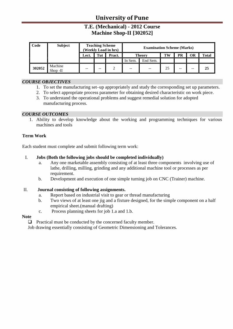
302052 Machine
Shop -II -- -- 2 -- -- 25 -- -- 25
COURSE OBJECTIVES 1. To set the manufacturing set–up appropriately and study the corresponding set up parameters.
2. To select appropriate process parameter for obtaining desired characteristic on work piece.
3. To understand the operational problems and suggest remedial solution for adopted
manufacturing process.
COURSE OUTCOMES
1. Ability to develop knowledge about the working and programming techniques for various
machines and tools
Term Work
Each student must complete and submit following term work:
I. Jobs (Both the following jobs should be completed individually) a. Any one marketable assembly consisting of at least three components involving use of
lathe, drilling, milling, grinding and any additional machine tool or processes as per
requirement.
b. Development and execution of one simple turning job on CNC (Trainer) machine.
II. Journal consisting of following assignments.
a. Report based on industrial visit to gear or thread manufacturing
b. Two views of at least one jig and a fixture designed, for the simple component on a half
empirical sheet.(manual drafting)
c. Process planning sheets for job 1.a and 1.b.
Note
Practical must be conducted by the concerned faculty member.
Job drawing essentially consisting of Geometric Dimensioning and Tolerances.
University of Pune
T.E. (Mechanical) - 2012 Course
Seminar [302053]
Code Subject Teaching Scheme
(Weekly Load in hrs) Examination Scheme (Marks)
Lect. Tut Pract. Theory TW PR OR Total
In Sem. End Sem.
302053 Seminar -- -- 2 -- -- -- -- 50 50
The Seminar topic must be related to one of the following
1. Mechanical Engineering
2. Interdisciplinary subjects
3. Recent trends in Engineering
INSTRUCTIONS FOR SEMINAR REPORT WRITING
It is important that the procedures listed below be carefully followed by all the students.
Prepare 3 COPIES of your Seminar report.
1. Limit your seminar report to preferably 20 – 25 pages
2. Header
For e.g. University of Pune
3. The footer
For e.g. Mechanical Engineering Institute Name, Mechanical Engineering Times New Roman 10 pt. and centrally aligned.
4. Page number as second line of footer, Times New Roman 10 Pt, centrally aligned
5. Print the report using
a) Letter quality computer printing.
b) The main part of report should be Times New Roman 12 pt. and justified.
c) Use 1.5 line spacing.
d) Entire report shall be one chapter. No chapters for Seminar report.
6. Use the paper size 8.5’’ × 11’’ or A4 (210 × 197 mm). Please follow the margins given below.
Margin Location Paper 8.5‟‟ × 11‟‟ Paper A4 (210 × 197 mm)
Top 1‟‟ 25.4 mm
Left 1.5‟‟ 37 mm
Bottom 1.25‟‟ 32 mm
Right 1‟‟ 25.4 mm
7. All paragraphs will be 1.5 line spaced with a one blank line between each paragraph. Each
paragraph will begin with without any indentation.
8. Section titles should be bold with 14 pt typed in all capital letters and should be left aligned.
9. Sub-Section headings should be aligning at the left with 12 pt, bold and Title Case (the first letter
of each word is to be capitalized).
10. Illustrations (charts, drawings, photographs, figures) are to be in the text. Use only illustrations
really pertinent to the text. Illustrations must be sharp, clear, black and white. Illustrations
downloaded from internet are not acceptable.
a) Illustrations should not be more than two per page. One could be ideal
b) Figure No. and Title at bottom with 12 pt
c) Legends below the title in 10 pt
d) Leave proper margin in all sides
e) Illustrations as far as possible should not be in xerox form.

University of Pune 11. Photographs if any should of glossy prints
12. Equations if any, should be typed in text (it should not be copied as image)
13. Please use SI system of units. If students would like to add the equivalent in inch-pound (British)
units, they must be stated in parenthesis after the SI units. In case the final result comes out in any
other units (say due to empirical formula etc.) covert the unit to SI unit.
14. Please number the pages on the front side, centrally below the footer
15. References should be either in order as they appear in the report or in alphabetical order by last
name of first author
16. Symbols and notations if any should be included in nomenclature section only
17. Following will be the order of report
i) Cover page and Front page as per specimen on separate sheet
ii) Certificate from Institute as per specimen on separate sheet
iii) Acknowledgement
iv) List of Figures
v) List of Tables
vi) Nomenclature
vii) Contents
18. All section headings and subheadings should be numbered. For sections use numbers 1, 2, 3, ….
and for subheadings 1.1, 1.2, …. etc and section subheadings 2.1.1, 2.1.2, …. etc.
19. References should be given in the body of the text and well spread. No verbatim copy or
excessive text from only one or two references. If figures and tables are taken from any reference
then indicate source of it. Please follow the following procedure for references
Reference Books
Collier, G. J. and Thome, J. R., “Convective boiling and condensation”, 3rd
ed., Oxford University
Press, UK, 1996, pp. 110 – 112.
Papers from Journal or Transactions
Jung, D. S. and Radermacher, R., “Transport properties and surface tension of pure and mixed
refrigerants”, ASHRAE Trans, 1991, 97 (1), pp. 90 – 98.
Bansal, P. K., Rupasinghe, A. S. and Jain, A. S., “An empirical correction for sizing capillary
tubes”, Int. Journal of Refrigeration, 1996, 19 (8), pp.497 – 505.
Papers from Conference Proceedings
Colbourne, D. and Ritter, T. J., “Quantitative assessment of flammable refrigerants in room air
conditioners”, Proc. of the Sixteenth International Compressor Engineering Conference and Ninth
International Refrigeration and Air Conditioning Conference, Purdue University, West Lafayette,
Indiana, USA, 2002, pp. 34 – 40.
Reports, Handbooks etc.
United Nations Environmental Programme, Report of the Refrigeration, Air Conditioning and
Heat Pumps, Technical Option Committee, 2002, Assessment - 2002.
ASHRAE Handbook: Refrigeration, 1994 (Chapter 44)
Patent Patent no, Country (in parenthesis), date of application, title, year.
Internet
www.(Site) [Give full length URL]
University of Pune
A Seminar on (TNR, 16pt, centrally aligned)
Title (TNR, 27pt, Bold, Centrally Aligned,
Title Case)
By (TNR, 16pt, Centrally Aligned)
Mr. Student’s Name (TNR, 16pt, Centrally Aligned)
Guided by (TNR, 16pt, Centrally Aligned)
Guide’s Name (TNR, 16pt, Centrally Aligned)
Institute
Logo
Department of Mechanical Engineering
Name of the Institute
[2011-12](TNR, 22pt, Title Case Centrally Aligned)
University of Pune
Name of the Institute
Institute
Logo
C E R T I F I C A T E
This is to certify that Mr/Miss. ............, has successfully completed the Seminar work
entitled “Performance analysis of……..” under my supervision, in the partial fulfilment of
Bachelor of Engineering - Mechanical Engineering, by University of Pune.
Date :
Place :
__________________ __________________
Guide Head Department
Name: Name:
__________________
Principal,
Seal Name: