university of oregon campus design standards …
TRANSCRIPT
UNIVERSITY OF OREGON CAMPUS DESIGN STANDARDS DIVISION 22 – PLUMBING
08/2019 Division 22 22 00 00 – Page 1 of 3
SECTION 22 00 00 - General Plumbing
Document revision history: 08/2019 – Original Publication Date Section Description of Change
PART 1 – GENERAL
1.1 Summary a. Section includes general provisions for Plumbing.
1.2 General Design Guidelines
a. Not applicable.
1.3 Submittals a. Submittal information will only be reviewed as related to this section. b. Submittals should have sufficient detail to determine compliance with specifications. c. Incomplete submittals will be rejected without review. d. Submittals should be for this complete specification section and not individual sections. e. Where appropriate, provide drawings and diagrams to indicate location and connections. f. BIM Execution Plan (BEP) to be followed for all equipment and drawings. g. Flushing plans. h. O&M documents – electronic searchable .pdf. i. Training plans. j. Mock-ups as required by Owner.
1.4 Qualifications a. Manufacturer: Company specializing in manufacturing products specified in this section with minimum thirty
(30) years documented experience. b. Installer: Company specializing in installing products specified in this section with minimum five (5) years
documented experience.
PART 2 – PRODUCTS a. As specified in each section. b. Substitutions by formal request and should be demonstrated to perform as specified.
PART 3 – EXECUTION
3.1 Installation a. All serviceable components to be accessible for maintenance and removal. Owner to approve acceptable
distance to components. b. Exterior placement of equipment must be approved by Owner. c. No items to be abandoned in place. d. Systems or components installed which require special tool to maintain or replace must be approved by Owner. e. All main risers must be provided with an access door (3’X3’). f. Locate serviceable equipment/components within corridors or above doorways. g. Components requiring regular maintenance should not exceed 14’, and 7’ in mechanical or electrical rooms.

UNIVERSITY OF OREGON CAMPUS DESIGN STANDARDS DIVISION 22 – PLUMBING
08/2019 Division 22 22 00 00 – Page 2 of 3
h. Isolation: • All floors at the main risers • Each zone or area of service • Drain down valves at low points • All equipment coil connections • Building service entrance • Both sides of control valves • Both sides of pumps
i. Potable hot water systems basis of design should be pumped recirculation. j. Provide access to sanitary sewer sampling point and acid waste sampling point for EH&S reporting. k. Refer to individual sections for specific requirements.
3.2 Accessibility of Equipment & Components a. Per the ‘Design Review Requirements’ at the beginning of this document, a drawing layer of ‘Maintenance
Access’ is to be incorporated into ALL drawings and system designs. This layer MUST be maintained through all phases of design and construction.
b. Access must be provided to read gages, thermometers, monometers, meters, etc. c. ALL intakes require access to properly maintain and clean. d. In mechanical and electrical rooms any components requiring routine service/maintenance must be installed /
mounted below 7ft in height. Prior to installation of any component above 7ft requires onsite review and explanation with FS Maintenance and/or FS Electrical Supervisor.
a. Inaccessible Equipment: • If after meetings, reviews, comments, etc., there are documented and/or discussed changes not
incorporated into the construction documents and installed equipment is not accessible for operation and maintenance, equipment shall be removed and reinstalled at no additional cost to the UO or the project. Discussions of payment will occur with the design team.
• ‘Accessible’ is defined as being capable of being reached without climbing or crawling under or over obstacles such as motors, pumps, belt guards, transformers, piping and ductwork. Access must not exceed 14ft in height, a typical ladder working height.
3.3 Piped Systems a. All piped systems with supply and return piping require the following: b. Dividing supply system into zones, areas of service, or by floor c. Isolation of each zone, area of service, or floor level from the main distribution lines. d. Drain down valves shall be provided at the low point in each zone, area of service, or floor level.
3.4 Interface with other products a. Installation must not compromise installation or access to other building systems or components.
3.5 Testing
a. All testing to be witnessed by Owner. b. Startup of equipment to be scheduled to allow for Owner witness.

UNIVERSITY OF OREGON CAMPUS DESIGN STANDARDS DIVISION 22 – PLUMBING
08/2019 Division 22 22 00 00 – Page 3 of 3
3.6 Training a. Furnish training plan for review by Owner at least two weeks prior to training. b. Training by qualified technicians knowledgeable in plumbing systems and components.

UNIVERSITY OF OREGON CAMPUS DESIGN STANDARDS DIVISION 22 – PLUMBING
08/2019 Division 22 22 05 19 – Page 1 of 2
SECTION 22 05 19 Meters and Gauges for Plumbing Piping
Document revision history: 08/2019 – Original Publication Date Section Description of Change
PART 1 – GENERAL
1.1 Summary a. Section includes meters and gauges for plumbing:
• Pressure gauges • Compound pressure gauges • Thermometers • Flow meters • Test plugs
1.2 General Design Guidelines a. Pressure gauges for pumps to be compound and installed on inlet and outlet of pump. b. Provide thermometers in the following locations:
• Inlet and outlet of coils, heat exchangers, chilled water supply and return to building. c. Provide isolation valves on gauges and thermometers for maintenance and replacement
1.3 Submittals
a. Product data, if product data submittal includes a listing of models, sizes, and options it is the responsibility of the Contractor to indicate specifics to be used on project.
1.4 Qualifications
a. Not applicable.
PART 2 – PRODUCTS
2.1 Pressure Gauges a. Basis of design: Ashcroft b. Case: Liquid filled c. Size: 4.5” diameter d. Mid-Scale Accuracy: 1 percent e. Range:
• Domestic and industrial water: 0 – 160 psi
2.2 Compound Gauges for Pumps a. Basis of design: Ashcroft b. Case: Liquid filled c. Size: 4.5” diameter d. Mid Scale Accuracy: 1 percent e. Range:
• 30 IMV – 160 psi

UNIVERSITY OF OREGON CAMPUS DESIGN STANDARDS DIVISION 22 – PLUMBING
08/2019 Division 22 22 05 19 – Page 2 of 2
2.3 Thermometers a. Basis of design: Ashcroft b. Case: Sealed, stainless steel c. Size: 5” diameter d. Connector type: Adjustable angle e. Mid-Scale Accuracy: 1 percent f. Range:
• Domestic and industrial water: 30 – 160 °F
2.4 Turbine Flow Meters a. Description: Vertical turbine flowmeter with sensor, indicator, and internal strainer b. Basis of design: Mueller c. Odometer type totalizing display d. Required for building service, makeup water, and irrigation.
2.5 Test Plugs a. Test port must extend past insulation. b. Provide at all digital and analog temperature and pressure sensors.
PART 3 – EXECUTION
3.1 Installation a. Installed gauges and thermometers such that the face is able to be read from the floor without a ladder.
3.3 Interface with other products
a. Not applicable.
3.4 Testing a. Not applicable.
3.5 Training
a. Provide training for all devices and equipment to include preventative maintenance, verify labeling is complete and correct, review location of all devices, and verify all testing is complete with associated documentation.
UNIVERSITY OF OREGON CAMPUS DESIGN STANDARDS DIVISION 22 – PLUMBING
08/2019 Division 22 22 05 23 – Page 1 of 4
SECTION 22 05 23 General Duty Valves for Plumbing Piping
Document revision history: 08/2019 – Original Publication Date Section Description of Change
PART 1 – GENERAL
1.1 Summary a. Section includes valves for plumbing service.
• Ball valves • Globe valves • Butterfly valves • Gate valves • Check valves • Drain valves
1.2 General Design Guidelines a. Not applicable.
1.3 Submittals a. Product data: If product data submittal includes a listing of models, sizes, and options it is the responsibility of
the Contractor to indicate specifics to be used on project. 1.4 Qualifications
a. Not applicable.
PART 2 – PRODUCTS
2.1 General Requirements for Valves a. Square head shut-off valves required at exterior locations. b. Building service shutoff / isolation valves:
• 2” and smaller: Ball valve • 2.5” and larger: Gate valve with rising stem • Valves to provide 100% positive shutoff
c. Drain valves: • Ball valve with threaded hose adapter and cap.
d. Provide stem extensions for valves in insulated piping. e. Valves 2.5” and larger located more than 10 feet from floor in mechanical rooms provide with chain operators. f. Provide full insulation around valve bodies where insulation is required. g. Provide chainwheel operators for valves 2.5” and larger installed more than 10 feet above the ground h. Valves for RO/DI water must be tin lined and spring closed. i. Threaded or flanged end connections only, exceptions listed below. j. Provide isolation valves at each floor in an accessible space adjacent to piping riser, at every room entrance,
and at every connection to equipment/fixture.

UNIVERSITY OF OREGON CAMPUS DESIGN STANDARDS DIVISION 22 – PLUMBING
08/2019 Division 22 22 05 23 – Page 2 of 4
k. Install threaded union on both sides of every threaded valve connection. l. Valves in insulated piping to have stem extension that extends beyond insulation.
2.2 Ball Valves a. Basis of design: Apollo b. 2” and smaller
• SWP: 150 psig • CWP: 600 psig • Body: Two piece bronze • Ends: Threaded • Seats: Reinforced Teflon (PTFE) • Stem: Bronze • Ball: Stainless steel • Port: Full • Packing: Adjustable
c. Lab air systems cleaned for oxygen use: • SWP: 150 psig • CWP: 600 psig • Body: Three piece bronze • Ends: Brazed • Seats: Reinforced Teflon (PTFE) • Stem: Stainless steel • Ball: Stainless steel • Port: Full • Packing: Adjustable
2.3 Globe valves
a. Basis of design: Apollo b. 2” and smaller:
• Class: 125 • CWP: 200 psig • Body: Bronze with integrated set and screw in bonnet • Ends: Threaded • Stem and Disc: PTFE • Handwheel: Malleable iron, bronze, or aluminum.
2.4 Butterfly Valves
a. Basis of design: Apollo b. 2.5” and larger:
• SWP: 150 psig • CWP: 200 psig • Body: Ductile iron • Ends: Flanged • Seats and liners: EPDM • Stem: Stainless steel
UNIVERSITY OF OREGON CAMPUS DESIGN STANDARDS DIVISION 22 – PLUMBING
08/2019 Division 22 22 05 23 – Page 3 of 4
• Disc: Bronze • Packing: Adjustable • Body and stem seals • Operators: Lever lock • Lug style only
2.5 Gate Valves
a. Basis of design: Apollo b. 2” and smaller
• Class: 150 • SWP: 150 psig • CWP: 200 psig • Body: Bronze • Ends: Threaded • Stem: Non-rising • Bonnet: Bronze with union • Packing gland: Brass, re-packable under pressure (not required for steam applications)
c. 2.5” and larger • Class: 150 • SWP: 150 psig • CWP: 200 psig • Body: Ductile iron • Ends: Flanged • Stem: Non-rising • Bonnet: Bolted • Wedge: Solid, bronze mounted • Packing gland: Brass, re-packable under pressure (not required for steam applications)
2.6 Check Valves
a. Basis of design: None b. 2” and smaller:
• Class: 125 • CWP: 200 psig • Body: Horizontal flow • Body material: Bronze • Ends: Threaded • Disc: Bronze, renewable seat and disc
c. 2.5” and larger: • Standard: MSS SP-80, Type 3 • Class: 125 • CWP: 200 psig • Body: Horizontal flow • Body material: Gray iron

UNIVERSITY OF OREGON CAMPUS DESIGN STANDARDS DIVISION 22 – PLUMBING
08/2019 Division 22 22 05 23 – Page 4 of 4
• Ends: Flanged • Disc: Iron, renewable seat and disc • Trim: Bronze • Bolted bonnets only
2.7 Drain Valves
a. Basis of design: None b. 2” and smaller:
• CWP: 600 psig • Body: Two piece bronze • Ends: Threaded with ¾ inch male hose threaded adapter • Seats: Reinforced Teflon (PTFE) • Stem: Stainless steel • Ball: Stainless steel • Port: Full • Packing: Adjustable • Cap: Brass with EPDM gasket and brass chain.
PART 3 – EXECUTION
3.1 Installation a. Valve handle swing in direction of flow. b. Soldered valves minimum 12” between main and branch pipe. c. Any piping installations with more than three pipes on a single support requires mockup for Owner to review
pipe spacing is adequate for maintenance and repair.
3.2 Interface with other products a. Not applicable.
3.3 Testing
a. Not applicable.
3.4 Training a. Provide training for all devices and equipment to include preventative maintenance, verify labeling is complete
and correct, review location of all devices, and verify all testing is complete with associated documentation.
UNIVERSITY OF OREGON CAMPUS DESIGN STANDARDS DIVISION 22 – PLUMBING
08/2019 Division 22 22 05 25 – Page 1 of 4
SECTION 22 05 25 Plumbing Specialties
Document revision history: 08/2019 – Original Publication Date Section Description of Change
PART 1 – GENERAL
1.1 Summary a. Section includes plumbing specialties and devices for plumbing service.
• Balancing valves • Backflow prevention valves • Pressure regulating valves • Thermostatic mixing valves • Pressure safety relief valves • Thermal expansion tanks • Water hammer arrestors • Di-electric unions • Trap primer valves • Wye strainers
1.2 General Design Guidelines
a. Not applicable.
1.3 Submittals a. Product data.
1.4 Qualifications
a. Not applicable.
PART 2 – PRODUCTS
2.2 Balancing Valves a. Basis of design: Armstrong CBV-VT b. Globe style for flow measurement, balancing, and positive shut-off. c. Furnish with preformed insulation jacket. d. Furnish low flow valves for piping
• ½” with flows less than 0.5 gpm • ¾” with flows less than 1 gpm
e. 2” and smaller • Body: Bronze • Ends: Threaded
f. 2.5” and larger • Body: Cast iron • Ends: Flanged
UNIVERSITY OF OREGON CAMPUS DESIGN STANDARDS DIVISION 22 – PLUMBING
08/2019 Division 22 22 05 25 – Page 2 of 4
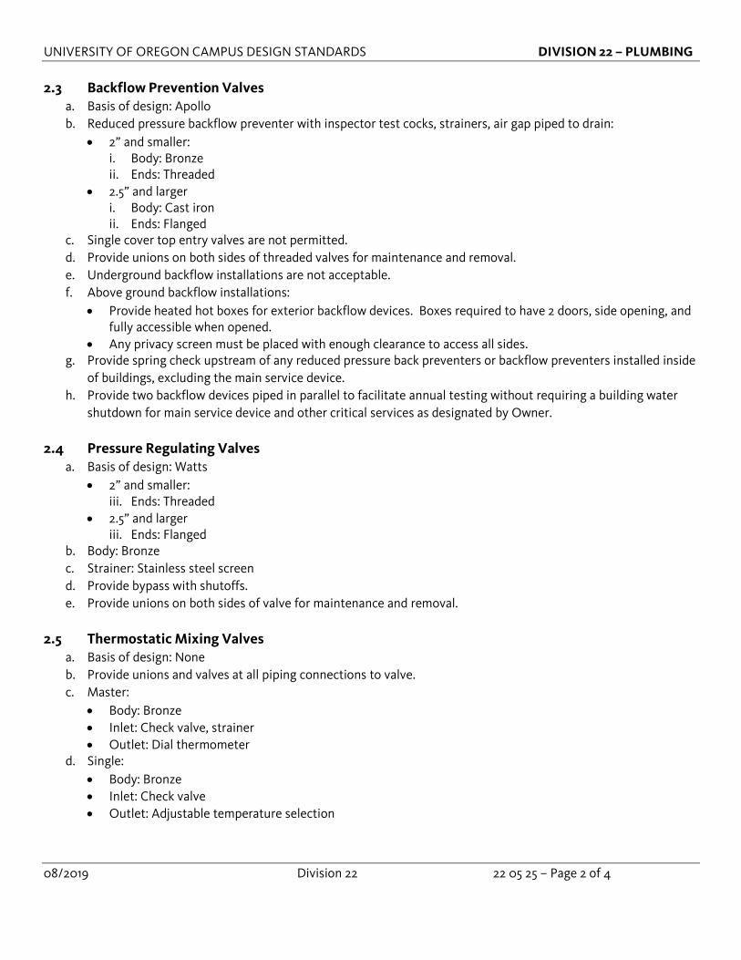
2.3 Backflow Prevention Valves
a. Basis of design: Apollo b. Reduced pressure backflow preventer with inspector test cocks, strainers, air gap piped to drain:
• 2” and smaller: i. Body: Bronze ii. Ends: Threaded
• 2.5” and larger i. Body: Cast iron ii. Ends: Flanged
c. Single cover top entry valves are not permitted. d. Provide unions on both sides of threaded valves for maintenance and removal. e. Underground backflow installations are not acceptable. f. Above ground backflow installations:
• Provide heated hot boxes for exterior backflow devices. Boxes required to have 2 doors, side opening, and fully accessible when opened.
• Any privacy screen must be placed with enough clearance to access all sides. g. Provide spring check upstream of any reduced pressure back preventers or backflow preventers installed inside
of buildings, excluding the main service device. h. Provide two backflow devices piped in parallel to facilitate annual testing without requiring a building water
shutdown for main service device and other critical services as designated by Owner.
2.4 Pressure Regulating Valves a. Basis of design: Watts
• 2” and smaller: iii. Ends: Threaded
• 2.5” and larger iii. Ends: Flanged
b. Body: Bronze c. Strainer: Stainless steel screen d. Provide bypass with shutoffs. e. Provide unions on both sides of valve for maintenance and removal.
2.5 Thermostatic Mixing Valves
a. Basis of design: None b. Provide unions and valves at all piping connections to valve. c. Master:
• Body: Bronze • Inlet: Check valve, strainer • Outlet: Dial thermometer
d. Single: • Body: Bronze • Inlet: Check valve • Outlet: Adjustable temperature selection
UNIVERSITY OF OREGON CAMPUS DESIGN STANDARDS DIVISION 22 – PLUMBING
08/2019 Division 22 22 05 25 – Page 3 of 4
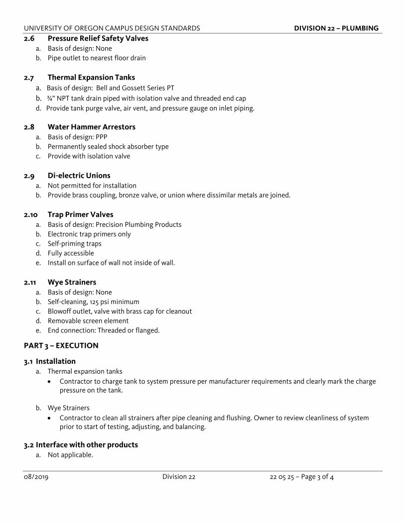
2.6 Pressure Relief Safety Valves a. Basis of design: None b. Pipe outlet to nearest floor drain
2.7 Thermal Expansion Tanks
a. Basis of design: Bell and Gossett Series PT b. ¾” NPT tank drain piped with isolation valve and threaded end cap d. Provide tank purge valve, air vent, and pressure gauge on inlet piping.
2.8 Water Hammer Arrestors
a. Basis of design: PPP b. Permanently sealed shock absorber type c. Provide with isolation valve
2.9 Di-electric Unions
a. Not permitted for installation b. Provide brass coupling, bronze valve, or union where dissimilar metals are joined.
2.10 Trap Primer Valves
a. Basis of design: Precision Plumbing Products b. Electronic trap primers only c. Self-priming traps d. Fully accessible e. Install on surface of wall not inside of wall.
2.11 Wye Strainers
a. Basis of design: None b. Self-cleaning, 125 psi minimum c. Blowoff outlet, valve with brass cap for cleanout d. Removable screen element e. End connection: Threaded or flanged.
PART 3 – EXECUTION
3.1 Installation a. Thermal expansion tanks
• Contractor to charge tank to system pressure per manufacturer requirements and clearly mark the charge pressure on the tank.
b. Wye Strainers • Contractor to clean all strainers after pipe cleaning and flushing. Owner to review cleanliness of system
prior to start of testing, adjusting, and balancing.
3.2 Interface with other products a. Not applicable.

UNIVERSITY OF OREGON CAMPUS DESIGN STANDARDS DIVISION 22 – PLUMBING
08/2019 Division 22 22 05 25 – Page 4 of 4
3.3 Testing a. Backflow prevention valves
• Contractor to test and document every backflow device per EWEB requirements.
3.4 Training a. Provide training for all devices and equipment to include preventative maintenance, verify labeling is complete
and correct, review location of all devices, and verify all testing is complete with associated documentation. b. Expansion tank pressure to be verified as makeup pressure set-point plus 2 psig and adjusted for elevation
differences between expansion tank and makeup water pressure regulator. • Training to include proper tank charging procedure • Expansion tank setting to be clearly marked on the tank prior to training

UNIVERSITY OF OREGON CAMPUS DESIGN STANDARDS DIVISION 22 – PLUMBING
08/2019 Division 22 22 05 53 – Page 1 of 3
SECTION 22 05 53 Identification for Plumbing Piping and Equipment
Document revision history: 08/2019 – Original Publication Date Section Description of Change
PART 1 – GENERAL
1.1 Summary a. Section includes identification for piping and valves, including nameplates, tags and markers.
1.2 General Design Guidelines
a. None.
1.3 Submittals a. As required by Section 22 00 00. b. Valve Schedule for each piping system, in tabular format. c. Valve naming and format.
1.4 Qualifications
a. None.
PART 2 – PRODUCTS
2.1. Equipment Nameplates a. Laminated plastic, engraved white letters on black background. Letter size ½ tall. b. Use self-tapping stainless screws, and contact adhesive where screws cannot or should not penetrate
equipment.
2.2. Valve Tags a. Metal – brass with stamped lettering. b. Solid brass chain fastener with S-hooks.
2.3. Pipe Labels
a. 6 inch and smaller - flexible vinyl tape with adhesive backing. b. 6 inch and larger – preformed c. Union Labels
a. White vinyl, self-adhesive, permanent. b. Red lettering, minimum ½ inch tall c. Labels at unions and di-electric unions to read “UNION”.
2.4 Ceiling Labels a. Label ceilings or ceiling grid (not the tile) where key serviceable components such as valves, equipment, etc. are
located, with a clear adhesive label and bold black lettering ½” tall indicating equipment ID.

UNIVERSITY OF OREGON CAMPUS DESIGN STANDARDS DIVISION 22 – PLUMBING
08/2019 Division 22 22 05 53 – Page 2 of 3
PART 3 – EXECUTION
3.1 General a. Identify all key shutoff valves.
3.2 Piping System Identification a. Label equipment and piping with description and direction of flow. b. Label piping every 10 feet, and on either side of penetrations through walls. c. Locate labels at intervals not to exceed 20 feet on center, within 3 feet of valves / equipment connections /
branch connections / wall, floor, or ceiling penetrations.
3.3 Valve Identification a. Identify valves with brass tags using system identification and valve sequence number as detailed in the
University of Oregon’s BIM execution plan. If the project is not required to perform BIM this document can be requested for use in this application.
3.4 Access Panel Identification a. Label all access doors with equipment name or general purpose of equipment behind access door with
stenciled sign or markers.
3.5 Interface with other products a. None.
3.6 Testing
a. None.
3.7 Training a. Review location of identification and labeling with Owner for approval.
PART 4 – PLUMBING LABEL LEGEND
GREEN BACKGROUND / WHITE LETTERING Domestic Cold Water Tempered Water Supply / Return R.O. Water Pumped Storm Drain Storm Drain Overflow Drain
YELLOW BACKGROUND / BLACK LETTERING Domestic Hot Water Supply / Return Industrial Hot Water Supply / Return Domestic Hot Water Pre-Heat Irrigation Water Industrial Cold Water Non-potable Water Natural Gas
BROWN BACKGROUND / WHITE LETTERING Sanitary Waste / Vent Grease Waste Pumped Sanitary Waste / Vent
BLUE BACKGROUND / WHITE LETTERING Plant Service Air Lab Compressed Air Lab Vacuum

UNIVERSITY OF OREGON CAMPUS DESIGN STANDARDS DIVISION 22 – PLUMBING
08/2019 Division 22 22 05 53 – Page 3 of 3
ORANGE BACKGROUND / BLACK LETTERING Lab Waste and Vent BLACK BACKGROUND / WHITE LETTERING Nitrogen Liquid Nitrogen GREY BACKGROUND / BLACK LETTERING CO2
UNIVERSITY OF OREGON CAMPUS DESIGN STANDARDS DIVISION 22 – PLUMBING
08/2019 Division 22 22 07 00 – Page 1 of 2
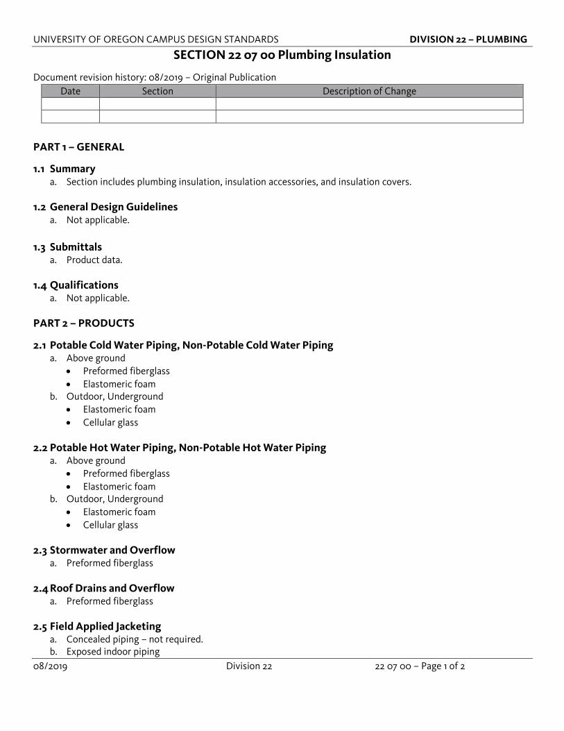
SECTION 22 07 00 Plumbing Insulation
Document revision history: 08/2019 – Original Publication Date Section Description of Change
PART 1 – GENERAL
1.1 Summary a. Section includes plumbing insulation, insulation accessories, and insulation covers.
1.2 General Design Guidelines
a. Not applicable.
1.3 Submittals a. Product data.
1.4 Qualifications
a. Not applicable.
PART 2 – PRODUCTS
2.1 Potable Cold Water Piping, Non-Potable Cold Water Piping a. Above ground
• Preformed fiberglass • Elastomeric foam
b. Outdoor, Underground • Elastomeric foam • Cellular glass
2.2 Potable Hot Water Piping, Non-Potable Hot Water Piping
a. Above ground • Preformed fiberglass • Elastomeric foam
b. Outdoor, Underground • Elastomeric foam • Cellular glass
2.3 Stormwater and Overflow
a. Preformed fiberglass
2.4 Roof Drains and Overflow a. Preformed fiberglass
2.5 Field Applied Jacketing
a. Concealed piping – not required. b. Exposed indoor piping

UNIVERSITY OF OREGON CAMPUS DESIGN STANDARDS DIVISION 22 – PLUMBING
08/2019 Division 22 22 07 00 – Page 2 of 2
• Mechanical room, food service, or areas exposed to cleaning i. PVC 30 mils thick
• Exposed indoor piping all other areas i. PVC 20 mils thick
c. Exposed outdoor • Aluminum weather proof jacketing
PART 3 – EXECUTION
3.1 Installation a. Provide continuous insulation through walls, floors, partitions. b. Provide insulation on all valves, fittings, and piping specialties. c. Valve and expansion joint blankets are to be easily removable and reusable. No Velcro fastening. d. Insulation inserts required at all points of piping support, insulation to be continuous. e. Outdoor aluminum jacketing must installed to prevent rain from seeping into the insulation, horizontal piping
the seam should face down and silicone caulking used on every seam.
3.2 Interface with other products a. Piping accessories and specialties, required to be insulated as part of piping system.
3.3 Testing
a. Not applicable.
3.4 Training a. Not applicable.

UNIVERSITY OF OREGON CAMPUS DESIGN STANDARDS DIVISION 22 – PLUMBING
08/2019 Division 22 22 11 00 – Page 1 of 3
SECTION 22 11 00 Plumbing Piping
Document revision history: 08/2019 – Original Publication Date Section Description of Change
PART 1 – GENERAL
1.1 Summary a. Section includes pipe, fittings, and joining methods for plumbing systems:
• Potable hot and cold water • Non potable hot and cold water • Sanitary waste, storm, and vent • Acid waste • Condensate • Trap primers • Mechanical grooved piping
1.2 General Design Guidelines
a. Not applicable.
1.3 Submittals a. Product data b. Pipe Testing, flushing, and sterilization plan c. Water chemical analysis report.
1.4 Qualifications
a. Not applicable
PART 2 – PRODUCTS
2.1 Potable Water Piping (CW, HWS, HWR) a. NPS 2” and smaller
• Type L, copper tube, hard drawn, solder joint fittings and joints. b. NPS 2.5” and larger
• Type L, copper tube, hard drawn, brazed joint fittings, brazed joints • Stainless steel piping, stainless steel fittings
c. Buried building service underslab or within 5 feet of building • Type K, copper tube, brazed joint fittings, brazed joints
2.2 Non Potable Water Piping (CW, HWS, HWR)
a. NPS 2” and smaller • Type L, copper tube, hard drawn, solder joint fittings and joints. • Crosslinked Polyethylene by owner approval if cost savings can be proven over copper.
b. NPS 2.5” and larger • Type L, copper tube, hard drawn, brazed joint fittings, brazed joints • Stainless steel piping, stainless steel fittings

UNIVERSITY OF OREGON CAMPUS DESIGN STANDARDS DIVISION 22 – PLUMBING
08/2019 Division 22 22 11 00 – Page 2 of 3
2.3 Sanitary Waste, Drainage, Vent Piping (D,W,V)
a. Above ground • Cast Iron, hubless • Copper type DWV, solder joint fittings, soldered joints
b. Underground within 5 feet of building • Cast iron, hubless
2.4 Acid Waste Piping
a. Basis of design: IPEX Enfield and Plenum Line • Mechanical joint piping to be used at fixture connections, acceptable for use throughout building. • Fused piping can be used in shafts / risers and in horizontal runs except at fixture connections.
2.5 Condensate Piping
a. Up to NPS 1: i. Type M hard drawn copper tubing, wrought copper fittings, soldered joints, lead free solder
b. NPS 1-1/4” and larger: ii. Type DWV hard drawn copper tubing, wrought copper fittings, soldered joints, lead free solder.
2.6 Trap Primer Piping
a. Above ground • Type L hard drawn copper tubing, wrought copper fittings, soldered joints
b. Underground within 5 feet of building • Type L soft annealed copper tubing, wrought copper fittings, brazed joints
• Crosslinked Polyethylene by owner approval if cost savings can be proven over copper.
2.7 Mechanical Grooved Piping a. Not permitted
PART 3 – EXECUTION
3.1 Installation a. Provide sleeves on piping passing though all penetrations including concrete, masonry, walls, partitions, etc. b. Provide insulation shields at all points of support on insulated piping. c. Provide heat trace on piping exposed to freezing conditions. d. Roof drain piping not permitted to be routed through building without Owner approval.
3.2 Interface with other products
a. Not applicable
3.3 Testing a. Notify Owner 7 days prior to any pressure testing and piping chemical treatment. b. Hydrostatic pressure testing required at a minimum of 125 psi.

UNIVERSITY OF OREGON CAMPUS DESIGN STANDARDS DIVISION 22 – PLUMBING
08/2019 Division 22 22 11 00 – Page 3 of 3
3.4 Training a. Provide training for all devices and equipment to include preventative maintenance, verify labeling is complete
and correct, review location of all devices, and verify all testing is complete with associated documentation.
UNIVERSITY OF OREGON CAMPUS DESIGN STANDARDS DIVISION 22 – PLUMBING
08/2019 Division 22 22 11 23 – Page 1 of 3
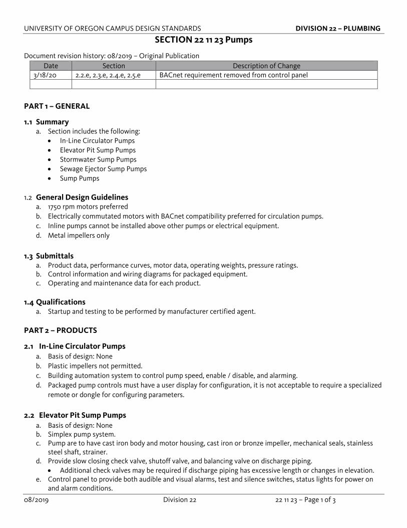
SECTION 22 11 23 Pumps
Document revision history: 08/2019 – Original Publication Date Section Description of Change
3/18/20 2.2.e, 2.3.e, 2.4.e, 2.5.e BACnet requirement removed from control panel
PART 1 – GENERAL
1.1 Summary a. Section includes the following:
• In-Line Circulator Pumps • Elevator Pit Sump Pumps • Stormwater Sump Pumps • Sewage Ejector Sump Pumps • Sump Pumps
1.2 General Design Guidelines a. 1750 rpm motors preferred b. Electrically commutated motors with BACnet compatibility preferred for circulation pumps. c. Inline pumps cannot be installed above other pumps or electrical equipment. d. Metal impellers only
1.3 Submittals
a. Product data, performance curves, motor data, operating weights, pressure ratings. b. Control information and wiring diagrams for packaged equipment. c. Operating and maintenance data for each product.
1.4 Qualifications
a. Startup and testing to be performed by manufacturer certified agent.
PART 2 – PRODUCTS
2.1 In-Line Circulator Pumps a. Basis of design: None b. Plastic impellers not permitted. c. Building automation system to control pump speed, enable / disable, and alarming. d. Packaged pump controls must have a user display for configuration, it is not acceptable to require a specialized
remote or dongle for configuring parameters.
2.2 Elevator Pit Sump Pumps a. Basis of design: None b. Simplex pump system. c. Pump are to have cast iron body and motor housing, cast iron or bronze impeller, mechanical seals, stainless
steel shaft, strainer. d. Provide slow closing check valve, shutoff valve, and balancing valve on discharge piping.
• Additional check valves may be required if discharge piping has excessive length or changes in elevation. e. Control panel to provide both audible and visual alarms, test and silence switches, status lights for power on
and alarm conditions.
UNIVERSITY OF OREGON CAMPUS DESIGN STANDARDS DIVISION 22 – PLUMBING
08/2019 Division 22 22 11 23 – Page 2 of 3
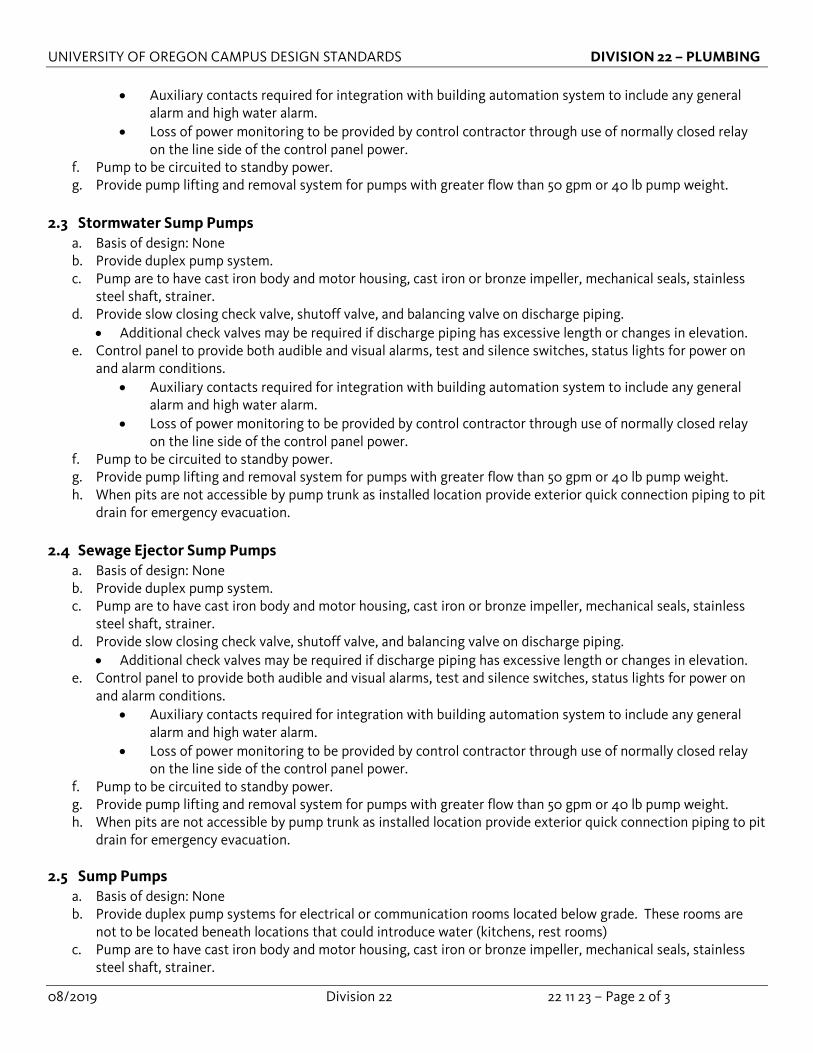
• Auxiliary contacts required for integration with building automation system to include any general alarm and high water alarm.
• Loss of power monitoring to be provided by control contractor through use of normally closed relay on the line side of the control panel power.
f. Pump to be circuited to standby power. g. Provide pump lifting and removal system for pumps with greater flow than 50 gpm or 40 lb pump weight.
2.3 Stormwater Sump Pumps
a. Basis of design: None b. Provide duplex pump system. c. Pump are to have cast iron body and motor housing, cast iron or bronze impeller, mechanical seals, stainless
steel shaft, strainer. d. Provide slow closing check valve, shutoff valve, and balancing valve on discharge piping.
• Additional check valves may be required if discharge piping has excessive length or changes in elevation. e. Control panel to provide both audible and visual alarms, test and silence switches, status lights for power on
and alarm conditions. • Auxiliary contacts required for integration with building automation system to include any general
alarm and high water alarm. • Loss of power monitoring to be provided by control contractor through use of normally closed relay
on the line side of the control panel power. f. Pump to be circuited to standby power. g. Provide pump lifting and removal system for pumps with greater flow than 50 gpm or 40 lb pump weight. h. When pits are not accessible by pump trunk as installed location provide exterior quick connection piping to pit
drain for emergency evacuation.
2.4 Sewage Ejector Sump Pumps a. Basis of design: None b. Provide duplex pump system. c. Pump are to have cast iron body and motor housing, cast iron or bronze impeller, mechanical seals, stainless
steel shaft, strainer. d. Provide slow closing check valve, shutoff valve, and balancing valve on discharge piping.
• Additional check valves may be required if discharge piping has excessive length or changes in elevation. e. Control panel to provide both audible and visual alarms, test and silence switches, status lights for power on
and alarm conditions. • Auxiliary contacts required for integration with building automation system to include any general
alarm and high water alarm. • Loss of power monitoring to be provided by control contractor through use of normally closed relay
on the line side of the control panel power. f. Pump to be circuited to standby power. g. Provide pump lifting and removal system for pumps with greater flow than 50 gpm or 40 lb pump weight. h. When pits are not accessible by pump trunk as installed location provide exterior quick connection piping to pit
drain for emergency evacuation.
2.5 Sump Pumps a. Basis of design: None b. Provide duplex pump systems for electrical or communication rooms located below grade. These rooms are
not to be located beneath locations that could introduce water (kitchens, rest rooms) c. Pump are to have cast iron body and motor housing, cast iron or bronze impeller, mechanical seals, stainless
steel shaft, strainer.

UNIVERSITY OF OREGON CAMPUS DESIGN STANDARDS DIVISION 22 – PLUMBING
08/2019 Division 22 22 11 23 – Page 3 of 3
d. Provide slow closing check valve, shutoff valve, and balancing valve on discharge piping. • Additional check valves may be required if discharge piping has excessive length or changes in elevation.
e. Control panel provide both audible and visual alarms, test and silence switches, status lights for power on and alarm conditions.
• Auxiliary contacts required for integration with building automation system to include any general alarm and high water alarm.
• Loss of power monitoring to be provided by control contractor through use of normally closed relay on the line side of the control panel power.
f. Pump to be circuited to standby power. g. Provide pump lifting and removal system for pumps with greater flow than 50 gpm or 40 lb pump weight. h. When pits are not accessible by pump trunk as installed location provide exterior quick connection piping to pit
drain for emergency evacuation. PART 3 – EXECUTION
3.1 Installation a. Not applicable.
3.2 Interface with other products
a. Building automation system
3.3 Testing a. Contractor to notify Owner a minimum of 7 days prior to equipment startup. b. Owner to witness startup and testing of pumps.
3.4 Training
a. Provide training for all devices and equipment to include preventative maintenance, verify labeling is complete and correct, review location of all devices, and verify all testing is complete with associated documentation.
b. Training to include preventative maintenance procedures, float adjustment, testing procedures, manual pump controls, review of operation and maintenance manuals, and motor / float replacement procedure.
c. Training to include demonstration of pump operation and alarming.
UNIVERSITY OF OREGON CAMPUS DESIGN STANDARDS DIVISION 22 – PLUMBING
08/2019 Division 22 22 30 00 – Page 1 of 3
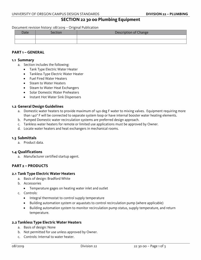
SECTION 22 30 00 Plumbing Equipment
Document revision history: 08/2019 – Original Publication Date Section Description of Change
PART 1 – GENERAL
1.1 Summary a. Section includes the following:
• Tank Type Electric Water Heater • Tankless Type Electric Water Heater • Fuel Fired Water Heaters • Steam to Water Heaters • Steam to Water Heat Exchangers • Solar Domestic Water Preheaters • Instant Hot Water Sink Dispensers
1.2 General Design Guidelines a. Domestic water heaters to provide maximum of 140 deg F water to mixing valves. Equipment requiring more
than 140° F will be connected to separate system loop or have internal booster water heating elements. b. Pumped Domestic water recirculation systems are preferred design approach. c. Tankless water heaters for remote or limited use applications must be approved by Owner. d. Locate water heaters and heat exchangers in mechanical rooms.
1.3 Submittals a. Product data.
1.4 Qualifications
a. Manufacturer certified startup agent.
PART 2 – PRODUCTS
2.1 Tank Type Electric Water Heaters a. Basis of design: Bradford White b. Accessories
• Temperature gages on heating water inlet and outlet c. Controls:
• Integral thermostat to control supply temperature • Building automation system or aquastats to control recirculation pump (where applicable) • Building automation system to monitor recirculation pump status, supply temperature, and return
temperature.
2.2 Tankless Type Electric Water Heaters a. Basis of design: None b. Not permitted for use unless approved by Owner. c. Controls: Internal to water heater.
UNIVERSITY OF OREGON CAMPUS DESIGN STANDARDS DIVISION 22 – PLUMBING
08/2019 Division 22 22 30 00 – Page 2 of 3
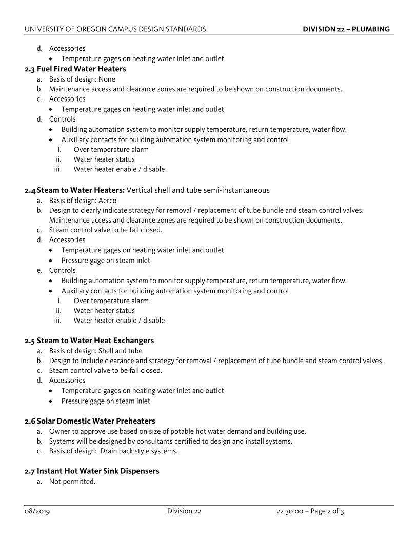
d. Accessories • Temperature gages on heating water inlet and outlet
2.3 Fuel Fired Water Heaters a. Basis of design: None b. Maintenance access and clearance zones are required to be shown on construction documents. c. Accessories
• Temperature gages on heating water inlet and outlet d. Controls
• Building automation system to monitor supply temperature, return temperature, water flow. • Auxiliary contacts for building automation system monitoring and control
i. Over temperature alarm ii. Water heater status
iii. Water heater enable / disable
2.4 Steam to Water Heaters: Vertical shell and tube semi-instantaneous a. Basis of design: Aerco b. Design to clearly indicate strategy for removal / replacement of tube bundle and steam control valves.
Maintenance access and clearance zones are required to be shown on construction documents. c. Steam control valve to be fail closed. d. Accessories
• Temperature gages on heating water inlet and outlet • Pressure gage on steam inlet
e. Controls • Building automation system to monitor supply temperature, return temperature, water flow. • Auxiliary contacts for building automation system monitoring and control
i. Over temperature alarm ii. Water heater status
iii. Water heater enable / disable
2.5 Steam to Water Heat Exchangers a. Basis of design: Shell and tube b. Design to include clearance and strategy for removal / replacement of tube bundle and steam control valves. c. Steam control valve to be fail closed. d. Accessories
• Temperature gages on heating water inlet and outlet • Pressure gage on steam inlet
2.6 Solar Domestic Water Preheaters
a. Owner to approve use based on size of potable hot water demand and building use. b. Systems will be designed by consultants certified to design and install systems. c. Basis of design: Drain back style systems.
2.7 Instant Hot Water Sink Dispensers
a. Not permitted.

UNIVERSITY OF OREGON CAMPUS DESIGN STANDARDS DIVISION 22 – PLUMBING
08/2019 Division 22 22 30 00 – Page 3 of 3
PART 3 – EXECUTION
3.1 Installation a. Not applicable.
3.2 Interface with other products
a. Not applicable.
3.3 Testing a. Notify Owner 7 days prior to equipment startup. b. All equipment to be started up by a manufacturer’s certified technician approved by Owner.
3.4 Training
a. Provide training for all devices and equipment to include preventative maintenance, verify labeling is complete and correct, review location of all devices, and verify all testing is complete with associated documentation.
b. Training to include preventative maintenance procedures, temperature adjustment, testing procedures, manual controls, replacement procedures, and review of operation and maintenance manuals.
c. Training to include demonstration of equipment operation and alarming. d. Training dates to be scheduled separately from startup site visits. Training cannot be scheduled until
equipment has been started up and all identified issues have been resolved.

UNIVERSITY OF OREGON CAMPUS DESIGN STANDARDS DIVISION 22 – PLUMBING
08/2019 Division 22 22 40 00 – Page 1 of 3
SECTION 22 40 00 Plumbing Fixtures
Document revision history: 08/2019 – Original Publication Date Section Description of Change
PART 1 – GENERAL
1.1 Summary a. Section includes the following:
• Water Closets • Urinals • Lavatories • Flushometers • Emergency Showers / Eyewash • Roof / Overflow Drains • Sinks • Drinking Fountains • Mop Sinks • Drains • Hydrants and Hose Bibbs • Cleanouts
1.2 General Design Guidelines a. Not applicable.
1.3 Submittals
a. Product data
1.4 Qualifications a. Not applicable
PART 2 – PRODUCTS
2.1 Water Closets a. Basis of design: Kohler b. Wall mounted with heavy duty carriers
• Review use of butt rest universal floor support for high weight fixtures. c. Floor mounted toilet fixtures not permitted in new construction d. 1.25 gallons per flush.
2.2 Urinals
a. Basis of design: Kohler b. Jet flush style c. Waterless not permitted d. 0.5 gallon per flush
UNIVERSITY OF OREGON CAMPUS DESIGN STANDARDS DIVISION 22 – PLUMBING
08/2019 Division 22 22 40 00 – Page 2 of 3
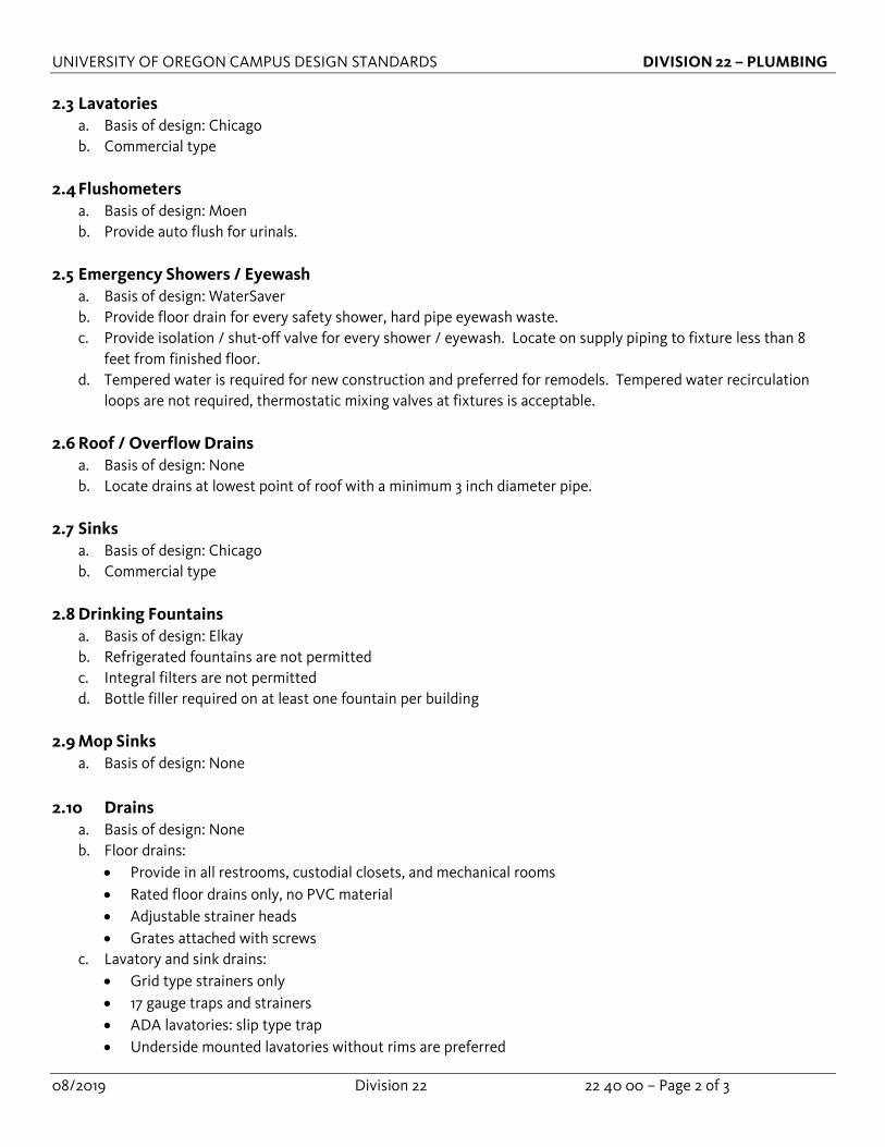
2.3 Lavatories a. Basis of design: Chicago b. Commercial type
2.4 Flushometers
a. Basis of design: Moen b. Provide auto flush for urinals.
2.5 Emergency Showers / Eyewash
a. Basis of design: WaterSaver b. Provide floor drain for every safety shower, hard pipe eyewash waste. c. Provide isolation / shut-off valve for every shower / eyewash. Locate on supply piping to fixture less than 8
feet from finished floor. d. Tempered water is required for new construction and preferred for remodels. Tempered water recirculation
loops are not required, thermostatic mixing valves at fixtures is acceptable.
2.6 Roof / Overflow Drains a. Basis of design: None b. Locate drains at lowest point of roof with a minimum 3 inch diameter pipe.
2.7 Sinks
a. Basis of design: Chicago b. Commercial type
2.8 Drinking Fountains
a. Basis of design: Elkay b. Refrigerated fountains are not permitted c. Integral filters are not permitted d. Bottle filler required on at least one fountain per building
2.9 Mop Sinks
a. Basis of design: None
2.10 Drains a. Basis of design: None b. Floor drains:
• Provide in all restrooms, custodial closets, and mechanical rooms • Rated floor drains only, no PVC material • Adjustable strainer heads • Grates attached with screws
c. Lavatory and sink drains: • Grid type strainers only • 17 gauge traps and strainers • ADA lavatories: slip type trap • Underside mounted lavatories without rims are preferred

UNIVERSITY OF OREGON CAMPUS DESIGN STANDARDS DIVISION 22 – PLUMBING
08/2019 Division 22 22 40 00 – Page 3 of 3
• Lavatory pipe insulation to be accessible
2.11 Hydrants and Hose Bibbs a. Basis of design:
• Wall Hydrants: Woodford • Hose Bibbs: Woodford
b. Wall Hydrants: • SS box type with concealed hose connection • ¼ turn non freeze with intergral vacuum breaker
c. Hose bibbs: • Locate minimum one hose bibb at the following locations
i. Building exterior every 150 feet ii. Loading docks
iii. 25 feet from any exterior equipment iv. Every rooftop level v. Mechanical rooms
vi. Restrooms at lavatories vii. Custodial closets • Rooftop locations require freeze less roof hydrant • Isolation valves for hose bibbs are required to be accessible and located on the building’s interior. • Control must be via a hose bibb key • Split box type not permitted.
2.12 Cleanouts a. Basis of design: None b. Provide fully accessible cleanouts for waste lines in each restroom. c. All wall cleanouts to be installed above the flood rim of the fixtures being served.
PART 3 – EXECUTION
3.1 Installation a. Not applicable
3.2 Interface with other products a. Not applicable
3.3 Testing a. Not applicable
3.4 Training a. Provide training for all devices and equipment to include preventative maintenance, verify labeling is
complete and correct, review location of all devices, and verify all testing is complete with associated documentation.
UNIVERSITY OF OREGON CAMPUS DESIGN STANDARDS DIVISION 23 – MECHANICAL
08/2019 Division 23 23 25 00 – Page 1 of 1
SECTION 23 25 00: HVAC Water Treatment
Document revision history: 08/2019 – Original Publication Date Section Description of Change
PART 1 – GENERAL
1.1 Summary a. Section includes cleaning and treatment for closed loop hydronic systems
1.2 General Design Guidelines
a. Not applicable.
1.3 Submittals a. Flushing and cleaning plan and report. b. O&M documents – electronic searchable .pdf. c. Training plans.
1.4 Qualifications a. Technical representative to direct flushing, cleaning, and pre-treatment.
PART 2 – PRODUCTS 2.1 Sterilization
a. Flush piping with water to remove sediment. b. Fill system with chlorine at concentration required by Authority Having Jurisdiction, duration of sterilization
dictated by chlorine concentration. c. Provide certificate of chlorination to Owner.
PART 3 – EXECUTION
3.1 Installation a. Reporting
• Contractor to submit report documenting flushing and cleaning process, chemicals used, and test results.
3.2 Interface with other products a. Not applicable.
3.3 Testing
a. All testing should be performed by manufacturer’s representative and results included in report.
3.4 Training a. Furnish training plan for review by Owner at least two weeks prior to training. b. Draft O&M’s submitted prior to first training session.