university of lisbon faculty of dental...
TRANSCRIPT

University of Lisbon
Faculty of Dental Medicine
INFLUENCE OF CONNECTION TYPE (INTERNAL VS. EXTERNAL)
ON IMPLANT IMPRESSION ACCURACY: AN IN VITRO STUDY
Rita de Cássia Cabral Ventura
Master Degree in Dental Medicine
2015

Dissertation supervised by
Dr. Helena Cristina de Oliveira Francisco
and
Prof. Doutor João Manuel Mendes Caramês
INFLUENCE OF CONNECTION TYPE (INTERNAL VS. EXTERNAL)
ON IMPLANT IMPRESSION ACCURACY: AN IN VITRO STUDY
University of Lisbon
Faculty of Dental Medicine
INFLUENCE OF CONNECTION TYPE (INTERNAL VS. EXTERNAL)
ON IMPLANT IMPRESSION ACCURACY: AN IN VITRO STUDY
Rita de Cássia Cabral Ventura
Master Degree in Dental Medicine
2015
Dissertation supervised by
Dr. Helena Francisco
Professor João Caramês

ii

iii
In memory of my Grandparents,
who never had the opportunity to see what I’ve become:
I hope you feel proud.

iv

v
Acknowledgements
Because no thesis is the work of just its author, i would like to express my gratitute...
To Dr.Helena Francisco, for sharing this challenge with me.
I have been truly fortunate to have an advisor who gave me the freedom to explore on
my own, and at the same time the guidance, motivation and support when my steps
faltered;
To Professor João Caramês, for the excellent input and suggestions for this work.
I am eternally grateful for providing me all the material and technical support and
enabling me to work in such a rich environment;
To Cláudia Caseiro and Manuela André, for their help in material acquisition;
To Fabio Nunes, for his patience and talent during all the amazing laboratory work;
To Professor Sofia Arantes de Oliveira and Dr.Filipa Chasqueira, for their
availability and kindness in assisting me during the microscope procedure;
To Professor Joana Fialho, who provided me an outstanding statistical analysis;
To my Parents, for their love and education, for their commitment in raising good
human beings and effort in providing us everything;
To my sister Vera and brother Artur, for being an inspiration;
To my Family, for their support and encouragement;
To my Friends, for all the remarkable moments during this journey;
And last but not least...
To Gonçalo, who makes it all worthwhile. This is not my work, this is our work.

vi

vii
Abbreviates
PMMA Polymethyl Methacrylate
PE Polyether
PVS Polyvynil Siloxane
IC Internal Connection
EC External Connection

viii

ix
Abstract
Purpose: The aim of the present study was to evaluate if there was any significant
difference in accuracy between implant-level impressions made on internal connection
and external connection implant systems. The null hypothesis tested was that the accuracy
of implant-impressions was not affected when internal connection or external connection
implants were used.
Materials and Methods: Two master models were fabricated with polyurethane
by duplicating an edentulous mandibular arch. In each model four implant analogs
(Biomet 3i®, Florida, USA) – internal connection (Group A) and external connection
(Group B) - were placed in the intra-mental foramen region, simulating a supra osseous
clinical environment and with longitudinal axis parallel to each other. The replicas were
numbered anti-clockwise from 1 to 4 based on a frontal view of the master cast.
For each group, reference bars machined to fit passively were fabricated using cobalt-
chromium alloy. Twenty medium-consistency polyether (Impregum™ Penta™; 3M
ESPE, Germany) impressions - 10 for each group - were made using the open-tray
technique. Each cast produced was assessed for accuracy by attaching the respective
reference framework with a single screw on analog number 1 and measuring the vertical
gap between each cylinder and the respective analog (2, 3 or 4) at four different points -
buccal, lingual, distal and mesial – using a toolmakers’ microscope.
Results: The results showed there were significant differences between internal
and external connections, comparing measurements in all analog/point combinations. It
was determined that in Group B (External connection) the vertical gaps were statistically
higher than the ones verified in Group A (Internal connection).
Conclusions: The results of this study suggest that internal connection implants
present better results on the accuracy of implant impressions comparing to external
connection implants. Implant-level impressions made on external connection implants
resulted in statistically lower accuracy than the internal connection group.
Keywords: Implant connection, Internal connection, External connection, Impression
accuracy.

x

xi
Resumo
A reabilitação com implantes dentários de pacientes parcial e completamente
edêntulos tem demonstrado elevadas taxas de sucesso clínico, consistentemente
suportadas pela literatura. A otimização deste sucesso está diretamente relacionada com
a passividade da infra-estrutura protética quando aparafusada a múltiplos implantes.
A passividade absoluta de uma prótese total fixa sobre implantes não é alcançável,
como resultado das inúmeras variáveis envolvidas no processo de fabricação da mesma.
No entanto, parece existir um certo nível de tolerância, sendo ainda desconhecido o grau
de desadaptação da prótese face aos implantes que conduzirá a complicações biológicas
e/ou mecânicas.
Um dos passos mais críticos para o sucesso a longo prazo de próteses implanto-
-suportadas é a precisão das impressões obtidas, que pode ser afetada por diversos fatores,
tais como a técnica de impressão (moldeira aberta vs. moldeira fechada; ferulizar vs não
ferulizar), o material de impressão, o tipo de impressão (convencional vs. digital) e a
angulação e número de implantes.
Até à data, a influência do tipo de conexão do implante (interna vs. externa) na
precisão de impressões em implantes permanece desconhecida. A informação existente
na literatura sobre o desempenho deste fator, tanto in vitro como in vivo, é nula.
Objetivo: O objetivo do presente estudo laboratorial foi avaliar a possível
existência de diferenças significativas entre a precisão de impressões à cabeça do
implante obtidas sobre implantes de conexão interna e de conexão externa.
A hipótese nula testada foi: a precisão de impressões sobre implantes não é
influenciada pelo sistema de conexão utilizado, seja ele interno ou externo.
Materiais e métodos: Foi obtido um modelo preliminar de gesso através da
duplicação de uma arcada mandibular edêntula. Quatro buracos foram feitos
bilateralmente, na região entre os foramens mentonianos, para a inserção de quatro
réplicas de conexão interna (Biomet 3i®, Florida, USA) com 4,10mm de diâmetro. As
réplicas foram colocadas simulando uma condição clínica supra-óssea, com eixos de
inserção paralelos entre si e fixadas com cera para permitir a sua remoção após fabricação
da barra de referência.

xii
Sobre as réplicas, foram colocados cilindros de fundição correspondentes e unidos
com cera, para posteriormente ser fundida uma barra de referência em crómio cobalto
para o grupo de conexão interna (Grupo A).
Por forma a garantir a mesma posição das réplicas em ambos os grupos, foi
fabricada uma barra de transferência: sobre as réplicas de conexão interna foram
colocados multi-units de 1mm para conexão interna e as respetivas coifas de impressão
(Biomet 3i®, Florida, USA) que foram ferulizadas usando resina acrílica
autopolimerizável (GC pattern™; GC Corp, Tokyo, Japan). De seguida, todo o complexo
foi removido do modelo e os componentes de conexão interna (multi-units e réplicas)
foram substituídos por componentes de conexão externa. Deste modo, as réplicas de
conexão externa foram inseridas no modelo inicial aparafusadas à barra de transferência.
Posteriormente, foi fundida uma barra de referência para o grupo de conexão
externa (Grupo B), seguindo o mesmo protocolo usado para o Grupo A. As barras de
referência fabricadas para os dois grupos foram utilizadas como forma de avaliar a
precisão dos modelos obtidos através das impressões.
Com o objetivo de garantir uma completa passividade, as réplicas foram
aparafusadas às respetivas barras de referência e, desta forma, reinseridas nos buracos do
modelo preliminar. Para produzir os modelos finais, foram feitas matrizes de silicone de
condensação (Zetalabor; Zhermack®, Badia Polesina, Italy) sobre o modelo de gesso com
a respetiva barra aparafusada e corridas a poliuretano (Sherapolan 2:1; Shera®, Lemförde,
Germany).
Obtiveram-se, assim, dois modelos (Grupo A e B) onde, em cada um, as réplicas
foram numeradas de 1 a 4 no sentido anti-horário, baseado numa vista frontal do modelo.
Para o procedimento de impressão, foram utilizadas moldeiras standard,
devidamente perfuradas para a técnica de moldeira aberta, sobre as quais foi aplicado
adesivo para poliéter (Impregum™; 3M ESPE).
Foi realizado um total de 20 impressões – 10 para cada grupo – utilizando poliéter
de consistência média (Impregum™ Penta™; 3M ESPE, Seefeld, Germany), de acordo
com as instruções do fabricante. A mistura do material de impressão foi feita através de
um sistema de automistura (Pentamix™ II; 3M ESPE, Seefeld, Germany) e parte do
material foi meticulosamente injetado em volta das coifas de impressão para garantir a
sua completa cobertura. A moldeira foi posicionada e mantida sob pressão manual
durante 6 minutos. Em todas as impressões, foram utilizadas coifas de impressão (Biomet
3i®, Florida, USA) para a técnica de moldeira aberta.
xiii
As impressões foram corridas a gesso tipo IV (GC Fujirock EP®; GC Corp, Tokyo,
Japan) misturado a vácuo e segundo as instruções do fabricante. Os modelos obtidos
foram mantidos a temperatura ambiente durante um período mínimo de 24 horas antes da
realização das medições.
A avaliação da precisão de cada modelo foi feita aparafusando a respetiva barra
de referência apenas na réplica número 1 e medindo a discrepância vertical através do
uso de um microscópio comparador (Toolmakers Microscope, Mitutoyo). As medições
foram efetuadas entre a base de cada cilindro da barra de referência e a respetiva réplica
(2, 3 ou 4), em quatro pontos diferentes – vestibular, lingual, mesial e distal.
A análise estatística de resultados foi realizada através do teste paramétrico T-
student quando se verificou que a amostra seguia uma distribuição normal. Por outro lado,
foi aplicado o teste não paramétrico Mann-Whitney quando esta condição não se verificou
(Os testes de Kolmogorov-Smirnov e Shapiro-Wilk foram usados para avaliar se os
resultados seguiam uma distribuição normal; o teste de Levene foi usado para determinar
a igualdade de variâncias). O nível de significância estabelecido foi de 5%.
Resultados: Os resultados demonstraram existir diferenças significativas entre os
grupos ao comparar as medições efetuadas para cada associação ponto/réplica específica.
A análise estatística determinou que no Grupo B (conexão externa) as
discrepâncias verticais observadas apresentaram valores estatisticamente superiores ao
Grupo A (conexão interna).
Conclusões: Tendo em conta as limitações deste estudo laboratorial, os resultados
sugerem que implantes de conexão interna apresentam melhores resultados na precisão
de impressões quando comparados com implantes de conexão externa.
Estudos futuros poderão proceder à avaliação e comparação de diferentes sistemas
de conexão de implantes, no que diz respeito à sua influência na precisão de impressões.
Além disso, seria importante avaliar in vivo se os valores de discrepância vertical obtidos
neste estudo são clinicamente significativos.
Palavras-chave: Conexão do Implante, Conexão Interna, Conexão Externa, Precisão da
impressão.

xiv

xv
Table of Contents
I. Introduction ............................................................................................................... 1
1. Factors may influence the accuracy of implant impressions .............................................. 2
1.1. Impression technique (Open-tray vs. Closed-tray) ................................................................. 2
1.2. Splinting vs. Nonsplinting .................................................................................................................. 3
1.3. Impression Material ............................................................................................................................... 4
1.4. Impression Type (Conventional vs. Digital) .............................................................................. 5
1.5. Implant angulation and number ........................................................................................................ 5
1.6. Other factors (Connection level – implant level/abutment level; Impression tray
type – stock/custom tray; Depth of implant placement) ................................................................... 6
1.7. Implant connection type (Internal vs. External) ....................................................................... 6
II. Materials and Methods ............................................................................................. 8
1. Type of study ............................................................................................................................................. 8
2. Study Design ............................................................................................................................................. 8
3. Reference bars construction ............................................................................................................... 8
3.1. Internal Connection ............................................................................................................................... 8
3.2. External Connection .............................................................................................................................. 9
4. Master casts construction .................................................................................................................. 10
5. Impression Procedure .......................................................................................................................... 11
6. Cast production protocol .................................................................................................................... 12
7. Measurement protocol ........................................................................................................................ 13
8. Statistical analysis ................................................................................................................................. 13
III. Results ..................................................................................................................... 15
1. Group A – Internal Connection ...................................................................................................... 15
2. Group B – External Connection ..................................................................................................... 16
3. Comparison between Groups .......................................................................................................... 17
IV. Discussion .............................................................................................................. 21
V. Conclusion .............................................................................................................. 27
VI. Appendices ........................................................................................................... xix
VII. References........................................................................................................... xxv

xvi
List of Tables and Figures
Table 1 - Statistical Comparison of Each Point between Implant Analogs –
Group A…………………………………………………………………………
15
Table 2 - Statistical Comparison of Each Point between Implant Analogs –
Group B…………………………………………………………………………
16
Table 3 - Statistical Comparison of Each Combination between Group A and
B…………………………………………………………………………………
17
Table 4 - Descriptive Statistics of the Vertical Gap in mm for the Two Groups
Tested - Buccal………………………………………………………………….
18
Table 5 - Descriptive Statistics of the Vertical Gap in mm for the Two Groups
Tested – Lingual………………………………………………………………...
19
Table 6 - Descriptive Statistics of the Vertical Gap in mm for the Two Groups
Tested – Mesial………………………………………………………………….
19
Table 7 - Descriptive Statistics of the Vertical Gap in mm for the Two Groups
Tested – Distal………………………………………………………………….
20
Table 8 - Materials, Manufacturers, Components and Batch Numbers………… xix
Table 9 - Impregum™ Penta™ use According to the Manufacturer’s
Instructions………………………………………………………………………………
xxi
Table 10 - Measurements of the Vertical Gaps in mm – Group A (Internal
Connection) …………………………………………………………………….
xxiii
Table 11 - Measurements of the Vertical Gaps in mm – Group B (External
Connection) …………………………………………………………………….
xxiv

xvii
Figure 1. Initial cast – IC………………………………………………………. 8
Figure 2. Reference bar wax-up – IC…………………………...……………… 8
Figure 3. Reference bar after casting- IC……………...……………………….. 9
Figure 4. Reference bar finished – IC………...………………………………... 9
Figure 5. 1mm-multiunits and impression copings in place…………………… 9
Figure 6. Transference bar with IC components……………...………………... 9
Figure 7. Transference bar with EC components……………..……………….. 10
Figure 8. Positioning of EC implant analogs…………………………………... 10
Figure 9. Reference bar wax-up – EC…………...……………………………... 10
Figure 10. Reference bar finished – EC…………...…………………………… 10
Figure 11. Master cast – EC after removing the silicone matrix……...……….. 11
Figure 12. Master cast – IC…………………………………………………….. 11
Figure 13. Polyether adhesive application……………………………………... 11
Figure 14. Polyether insertion………………………………………………….. 11
Figure 15. Polyether injection around copings………………………………… 12
Figure 16. Impression procedure –open tray technique………………………... 12
Figure 17. EC cast – upper view……………………………………………….. 12
Figure 18. EC cast – front view………………………………………………... 12
Figure 19. Reference bar with a single screw on analog number 1………...….. 13
Figure 20. Toolmakers’ microscope…………...………………………………. 13
Figure 21. Box-whisker plots of the vertical gap in mm for the two groups
tested buccal points……………………………………………………………..
18
Figure 22. Box-whisker plots of the vertical gap in mm for the two groups
tested – lingual points……………………………………………..………….....
19
Figure 23. Box-whisker plots of the vertical gap in mm for the two groups
tested – mesial points…………………………………………..…………….....
19
Figure 24. Box-whisker plots of the vertical gap in mm for the two groups
tested – distal points…………………………………………………………….
20
Figure 25. Measurement procedure according to user’s manual - Mitutoyo
Toolmaker’s Microscope………………………………………………………..
xxii

xviii
INFLUENCE OF CONNECTION TYPE (INTERNAL VS. EXTERNAL) ON IMPLANT IMPRESSION ACCURACY: AN IN VITRO STUDY
1
I. Introduction
The rehabilitation of partially and completely edentulous patients with dental
implants presents clinical success consistently supported by the literature. Longitudinal
studies report an implant success rate of 96-99% in the mandible and 80-90% in the
maxilla, for a period up to 15 years. Optimization of this success is directly related to the
fabrication of passively fitting implant superstructures (Aguilar et al., 2010, Akalin et al.,
2013).
According to the recommended standard of practice, clinicians’ aim is to provide
fixed implant prostheses that exhibit passive fit when connected to multiple abutments.
The contact of all fitting surfaces is thought to minimize the uncontrolled stresses and
strains within the implant components, the prosthesis and surrounding bone in the absence
of an applied external load (Abduo and Judge, 2014, Buzayan and Yunus, 2014).
Furthermore, because of the precise fit of implant components and the rigid connection
of implant to bone, small discrepancies can lead to stress applied to the implants when
the framework is screwed down (Del'Acqua et al., 2010a).
Several investigators have described the effect of accurately fitted complete-arch
fixed implant prosthesis on long-term success (Papaspyridakos et al., 2011).
Although absolute passive fit of implant fixed complete dental prostheses does
not seem attainable as a result of the number of variables involved in the process, a level
of biological tolerance seems to exist. However, it is still unclear which at degree of
prosthesis misfit will lead to biologic and/or mechanical complications (Papaspyridakos
et al., 2014). Biologically, marginal discrepancy from misfit may cause unfavorable soft
and/or hard tissue reactions like periimplant bone loss due to increase plaque
accumulation. On the other hand, mechanical complications such as screw loosening,
screw fracture, implant fracture and prosthetic-component strain and fracture are
expected to emerge from compromised fit of implant prosthesis (Abduo and Judge, 2014,
Lee et al., 2008b). In this context, an accurate three-dimensional reproduction of the
intraoral position of the implants through the impression phase is necessary.
The clinical fit of an implant prosthesis at the implant-abutment junction is
directly dependent on the accuracy of impression technique and cast fabrication
(Papaspyridakos et al., 2014). Accurate implant impressions play a significant role and
serve as a starting point in the process of producing good working casts, along with other

INFLUENCE OF CONNECTION TYPE (INTERNAL VS. EXTERNAL) ON IMPLANT IMPRESSION ACCURACY: AN IN VITRO STUDY
2
contributing factors, such as pouring material/technique and machining tolerance of the
prosthodontic components (Baig, 2014). Clinically, additional factors, such as number,
angulation, and depth of implants may affect the accuracy of implant impressions
(Papaspyridakos et al., 2011).
One of the most critical steps for the long-term success of implant prosthesis is
the accuracy during the impression procedure, which may be affected by factors such as
impression technique (open-tray vs. closed-tray; splinting vs. nonsplinting), impression
material, impression type (conventional vs. digital) and implant angulation and number
(Baig, 2014, Moreira et al., 2015).
Numerous studies have focused on the accuracy of multiple-implant impressions
in completely edentulous arches, but no specific guidelines have been laid out pertaining
to impression making in this particular situation (Papaspyridakos et al., 2014).
1. Factors may influence the accuracy of implant impressions
1.1. Impression technique (Open-tray vs. Closed-tray)
An ideal impression technique would require minimal time and would be easy to
perform, inexpensive, comfortable for the patient and, of course, give the best results
(Del'Acqua et al., 2010a).
Several impression techniques have been proposed to provide a definitive cast that
will ensure accurate fit of the prostheses on osseointegrated implants. There are two
primary techniques: The transfer technique and the pick-up technique. The transfer
technique uses tapered copings and a closed tray to make an impression. The copings are
connected to the implants, and an impression is made and separated from the mouth,
leaving the copings intraorally. The copings are removed and connected to the implant
analogs, and then the coping-analog assemblies are reinserted in the impression before
fabricating the definitive cast. The pick-up technique uses square copings and an open
tray, allowing the coronal end of the impression coping screw to be exposed. Before
removing the tray, the copings are unscrewed to be removed along with the impression.
The implant analogs are connected to the copings to fabricate the definitive cast (Lee et
al., 2008b).
Twenty in vitro and one clinical study compared the accuracy with open-tray
(direct, pickup) vs closed-tray (indirect, transfer) impression techniques. Nine in vitro
studies reported that the open-tray technique was more accurate than the closed-tray for

INFLUENCE OF CONNECTION TYPE (INTERNAL VS. EXTERNAL) ON IMPLANT IMPRESSION ACCURACY: AN IN VITRO STUDY
3
completely edentulous patients (Al Quran et al., 2012, Assif et al., 1992, Barrett et al.,
1993, Carr, 1991, Martinez-Rus et al., 2013, Mostafa et al., 2010, Naconecy et al., 2004,
Phillips et al., 1994, Stimmelmayr et al., 2012). Ten in vitro studies reported no difference
(Chang et al., 2012, Del'Acqua et al., 2008, Del'acqua et al., 2012, Fernandez et al., 2013,
Herbst et al., 2000, Humphries et al., 1990, Mpikos et al., 2012, Rashidan et al., 2012,
Spector et al., 1990, Wenz and Hertrampf, 2008) and one in vitro study reported that the
closed-tray was more accurate (Burawi et al., 1997). One clinical study reported that the
open-tray was more accurate (Stimmelmayr et al., 2013).
In situations where four or more implants are used, a greater number of studies
showed more accurate impressions with the open-tray technique (Papaspyridakos et al.,
2014).
1.2. Splinting vs. Nonsplinting
Splinting of impression copings using a rigid material has been advocated as a
technique to prevent individual coping movement and to take advantage of the
stabilization of the impression copings during the impression making and analog
attachment procedures (Akalin et al., 2013, Lee et al., 2008b).
Most of the studies used polymethyl methacrylate (PMMA) autopolymerizing
acrylic resin as the splinting material of choice and different techniques have been tested,
such as dental floss, prefabricated acrylic resin bars and stainless steel burs (Naconecy et
al., 2004, Papaspyridakos et al., 2012). Nevertheless, distortion can result from the
residual polymerization contraction of the resin used for splinting. The use of new
splinting materials such as composite resin or visible light polymerizing acrylic resin
showed better results (Stimmelmayr et al., 2013, Papaspyridakos et al., 2012, Del'Acqua
et al., 2010b).
Twenty-two in vitro and three clinical studies compared the accuracy of splinted
vs nonsplinted impression techniques. Twelve in vitro studies reported that the splinted
technique was more accurate than the nonsplinted technique (Al Quran et al., 2012, Assif
et al., 1992, Assif et al., 1996, Avila et al., 2012, Del'Acqua et al., 2010b, Hariharan et
al., 2010, Martinez-Rus et al., 2013, Naconecy et al., 2004, Ongul et al., 2012,
Stimmelmayr et al., 2012, Vigolo et al., 2004, Vigolo et al., 2003), nine in vitro studies
reported that there was no difference (Barrett et al., 1993, Chang et al., 2012, Del'Acqua
et al., 2008, Herbst et al., 2000, Hsu et al., 1993, Humphries et al., 1990, Kim et al., 2006,
INFLUENCE OF CONNECTION TYPE (INTERNAL VS. EXTERNAL) ON IMPLANT IMPRESSION ACCURACY: AN IN VITRO STUDY
4
Mostafa et al., 2010, Spector et al., 1990) and one in vitro study (Phillips et al., 1994)
reported that the nonsplinted technique was more accurate. The three clinical studies
demonstrated that the splinted technique was more accurate than the nonsplinted
technique and recommended this technique for clinical use (Papaspyridakos et al., 2012,
Papaspyridakos et al., 2011, Stimmelmayr et al., 2013).
The splinted impression technique was more accurate than the nonsplinted
conventional impression technique for completely edentulous patients (Papaspyridakos
et al., 2014). Nevertheless, authors have identified potential problems with the spinted
technique, such as fracture of the connection between the splint material and the
impression copings, in particular due to shrinkage of splint material (Moreira et al., 2015).
1.3. Impression material
The properties of an impression material, including rigidity and dimensional
stability, can influence the accuracy of the implant impression, the accuracy of the solid
implant cast, and ultimately, the accuracy of the cast implant framework. When using the
direct implant impression technique, the impression material must fulfill two
requirements: 1) rigidity to hold the direct impression coping and to prevent accidental
displacement of the coping when an abutment is connected, and 2) minimal positional
distortion between abutment replicas as compared with their intraoral implant abutments
(Wee, 2000).
A rigid elastomeric impression material, such as polyether (PE), would secure the
impression copings accurately, and it has dimensional stability, high resistance to
permanent deformation, and high primary shear resistance with little creep under
compressive forces, making it an optimal material for making impressions of implants.
Polyvynil siloxane (PVS) impression materials have been widely accepted because of
their excellent dimensional stability, superior recovery from deformation, and precise
reproduction of details (Del'Acqua et al., 2010a).
In recent years, superior chemical and physical properties have made PE and PVS
the materials of choice for implant impression. To date, many researchers have evaluated
implant impression accuracy and found better results with PE and PVS versus
condensation silicone, polysulfide, irreversible hydrocolloid, and plaster materials
(Akalin et al., 2013, Lee et al., 2008b).

INFLUENCE OF CONNECTION TYPE (INTERNAL VS. EXTERNAL) ON IMPLANT IMPRESSION ACCURACY: AN IN VITRO STUDY
5
Among the analyzed papers, the majority of the studies reported no difference
between PE and PVS (Aguilar et al., 2010, Akalin et al., 2013, Assif et al., 1999, Barrett
et al., 1993, Chang et al., 2012, Ferreira et al., 2012, Mostafa et al., 2010, Ortorp et al.,
2005, Spector et al., 1990, Wee, 2000, Wenz and Hertrampf, 2008) while one study
reported better accuracy with PE (Del'Acqua et al., 2010a).
A systematic review concluded that the accuracy of implant impressions is not
affected by the impression material (PE and PVS) for completely edentulous patients
(Papaspyridakos et al., 2014).
1.4. Impression type (Conventional vs. Digital)
The reproduction of dental implants in the oral cavity avoiding conventional
impressions overcomes some problems of the indirect method. Digital impression
scanners eliminate tray selection, dispensing and setting of impression materials,
disinfection, and impression shipping to the laboratory, while increased patient comfort
may be an additional advantage (Papaspyridakos et al., 2014). Limitations pertain to the
additional cost of purchasing an intraoral scanner and the learning curve for adjusting to
the new treatment modality (Papaspyridakos et al., 2015).
Research on digital implant impressions for completely edentulous jaws is limited
to a few in vitro studies (Abdel-Azim et al., 2014, Papaspyridakos et al., 2015).
Papaspyridakos et al., 2015 concluded that digital implant impressions are as accurate as
conventional implant impressions. Abdel-Azim et al., 2014 reported that, for complete-
arch frameworks, the digital impression resulted in an overall more accurate fit when
compared to the conventional closed-tray impression.
1.5. Implant angulation and number
Some authors reported that when multiple implants are placed with different
angulations, the distortion of the impression material on removal increases. Also, this
effect may be heightened by an increasing number of implants (Assuncao et al., 2004,
Carr, 1991, Sorrentino et al., 2010).
Conrad, et al. 2007 reported that the acceptable angulation of the implant that will
not have an adverse effect on the impression accuracy was around 15º. They also
demonstrated that accuracy has as well been shown to be inversely affected by number
and angulation of the implants.

INFLUENCE OF CONNECTION TYPE (INTERNAL VS. EXTERNAL) ON IMPLANT IMPRESSION ACCURACY: AN IN VITRO STUDY
6
To clarify the relation between the angulation effect and the numbers of the
implant, more studies are required (Lee et al., 2008b).
1.6. Other factors (Connection level – implant level/abutment level; Impression tray
type – stock/custom tray; Depth of implant placement)
Other studies examined the effects of various factors on the accuracy of implant
impressions, such as different connection levels (implant level and abutment level)
(Alikhasi et al., 2011, Bartlett et al., 2002, Daoudi et al., 2001), different impression trays
(Burns et al., 2003, Simeone et al., 2011) and implant depth (Lee et al., 2008a).
Too few studies were available to draw any conclusions. Further studies,
including clinical trials, are required to provide more evidence about clinical factors that
affect the implant impression accuracy.
1.7. Implant connection type (Internal vs. External)
One of the features that has been the object of debate among the systems is the
design of the connection that allows the prosthetic suprastructure to be attached to the
implants. Two types of connections are available: external and internal connection. While
the external connection (EC) usually has an external hexagon on the implant platform,
the internal connection (IC) can be divided into internal hexagon, internal octagon and
Morse taper connection (Goiato et al., 2015).
Historically, the Bränemark system was characterized by an external hexagon
which was developed to facilitate implant insertion and provide an antirotational
mechanism. However, this configuration has some drawbacks due to the existence of a
microgap in the implant-abutment interface and to its limited height. For this reason, it
has been hypothesized that, under high occlusal loads, the external hexagon might allow
micromovements of the abutment, consequently causing instability of the
implant/abutment connection, which may result in abutment screw loosening or even
fracture. IC implants were therefore introduced to increase the implant-abutment contact
area, providing greater stability and bacterial seal (Goiato et al., 2015, Gracis et al., 2012).
To date, there is no in vivo or in vitro study that has directly compared the
influence of internal and external implant connections for abutments/reconstructions on
the accuracy of implant-level impressions. All in vitro studies reported separately on the
two connection designs and they used different protocols. Therefore, the data could not

INFLUENCE OF CONNECTION TYPE (INTERNAL VS. EXTERNAL) ON IMPLANT IMPRESSION ACCURACY: AN IN VITRO STUDY
7
be compared and no clinical recommendation can be made (Gracis et al., 2012,
Papaspyridakos et al., 2014).
For this reason, the purpose of the present study is to evaluate if there is any
significant difference in accuracy between implant-level impressions made on IC and EC
implant systems. The following null hypothesis was tested in this study: (1) There were
no differences in implant-level impressions accuracy between IC and EC implants.

INFLUENCE OF CONNECTION TYPE (INTERNAL VS. EXTERNAL) ON IMPLANT IMPRESSION ACCURACY: AN IN VITRO STUDY
8
II. Materials and Methods
1. Type of study
In vitro study.
2. Study design
This study compared the influence of two different types of implant connection
on impression accuracy: Group A (internal connection - IC) and Group B (external
connection - EC). For each group, 10 sample impressions were made from a standardized
master cast. After pouring, measurements were made in each working cast and the
differences between them were analyzed.
3. Reference bars construction
3.1. Internal connection
A dental stone cast was fabricated by duplicating an edentulous mandibular arch.
Four slightly oversized holes were made bilaterally in the intra-mental foramen region to
insert four internal connection implant analogs (Biomet 3i®, Florida, USA) with 4,10mm
diameter. The implant analogs were placed simulating a supra osseous clinical
environment, parallel to each other and fixed using wax to make their removal possible
after fabrication of the framework (Figure 1).
Corresponding burnout cylinders were placed on the implant analogs and splinted
with wax (Figure 2) in order to fabricate a cobalt-chromium alloy framework (Figures 3
and 4).
Figure 1. Initial cast – IC. Figure 2. Reference bar wax-up – IC.

INFLUENCE OF CONNECTION TYPE (INTERNAL VS. EXTERNAL) ON IMPLANT IMPRESSION ACCURACY: AN IN VITRO STUDY
9
3.2. External connection
To ensure the same position of implant analogs on both groups, a transference bar
was fabricated using IC 1mm-multi-units and respective multi-unit impression copings
(Biomet 3i®, Florida, USA) (Figure 5).
The copings were splinted using PMMA autopolymerizing acrylic resin (GC
pattern™; GC Corp, Tokyo, Japan) (Figure 6).
Then, the complex was removed from the cast and the IC multi-units and implant
analogs were substituted by EC components (Figure 7).
The EC analogs were incorporated into the stone cast attached to the transference
bar (Figure 8).
Figure 3. Reference bar after casting- IC. Figure 4. Reference bar finished – IC.
Figure 5. 1mm-multiunits and
impression copings in place.
Figure 6. Transference bar with
IC components.

INFLUENCE OF CONNECTION TYPE (INTERNAL VS. EXTERNAL) ON IMPLANT IMPRESSION ACCURACY: AN IN VITRO STUDY
10
Next, a framework for EC group was fabricated, using the same protocol used for
the IC reference bar (Figures 9 and 10).
The reference bars were used as a standard to evaluate the accuracy of casts
produced from impressions.
4. Master casts construction
For both groups, implant analogs were attached to the respective reference
frameworks and then inserted into the holes on the stone cast, in order to guarantee a
complete passive fit. A matrix for pouring the definitive master casts was made using
condensation silicone (Zetalabor; Zhermack®, Badia Polesina, Italy) over the stone cast
with the respective reference bar attached.
Two master models (EC and IC) were fabricated with polyurethane (Sherapolan
2:1; Shera®, Lemförde, Germany) (Figures 11 and 12).
Figure 7. Transference bar with
EC components.
Figure 8. Positioning of EC implant
analogs.
Figure 9. Reference bar wax-up – EC. Figure 10. Reference bar finished – EC.

INFLUENCE OF CONNECTION TYPE (INTERNAL VS. EXTERNAL) ON IMPLANT IMPRESSION ACCURACY: AN IN VITRO STUDY
11
The four implant analogs were numbered anti-clockwise from 1 to 4 based on a
frontal view of the master cast.
5. Impression procedure
Acrylic stock trays were used for all impressions in the unsplinted open-tray
technique. Four openings were drilled to allow access for the coping screws and a thin
layer of polyether adhesive (Impregum™; 3M ESPE, Seefeld, Germany) was applied to
improve adhesion (Figure 13).
Twenty medium - consistency polyether (Impregum™ Penta™; 3M ESPE,
Seefeld, Germany) impressions were made - ten for each model/group - in accordance
with manufacturer’s directions. The impression material was mixed with an automatic
mixing device (Pentamix™ II; 3M ESPE, Seefeld, Germany) (Figure 14) and part of the
material was meticulously injected with a syringe (Penta Elastomer syringe; 3M ESPE,
Seefeld, Germany) around the impression copings to ensure complete coverage of the
Figure 11. Master cast – EC
after removing the silicone matrix.
Figure 12. Master cast – IC.
Figure 13. Polyether adhesive application. Figure 14. Polyether insertion.

INFLUENCE OF CONNECTION TYPE (INTERNAL VS. EXTERNAL) ON IMPLANT IMPRESSION ACCURACY: AN IN VITRO STUDY
12
copings (Figure 15). The tray was seated on master cast with hand pressure throughout
the setting time - 6 minutes (Figure 16).
The guide pins were unscrewed so that the transfer copings remained in the
impression when the tray was removed.
For all impressions, implant transfer copings (Biomet 3i®, Florida, USA) for the
open tray technique were used.
6. Cast production protocol
Standardized laboratory procedures were performed after at least 30 minutes.
First, matching implant analogs were attached manually to the transfer copings.
Then, the impressions were poured with type IV dental stone (GC Fujirock EP®;
GC Corp, Tokyo, Japan) and vacuum-mixed following manufacturer recommendations
(Figures 17 and 18). A single operator performed all laboratory procedures. All casts
were stored at room temperature for a minimum of 24 hours before measurements were
made.
Figure 15. Polyether injection around
copings. Figure 16. Impression procedure –
open tray technique.
Figure 17. EC cast – upper view. Figure 18. EC cast – front view.

INFLUENCE OF CONNECTION TYPE (INTERNAL VS. EXTERNAL) ON IMPLANT IMPRESSION ACCURACY: AN IN VITRO STUDY
13
Figure 19. Reference bar with a single screw
on analog number 1.
7. Measurement protocol
Each cast produced was assessed for accuracy by attaching the respective
reference framework with a single screw on analog number 1 (Figure 19) and measuring
the vertical fit discrepancy using a toolmakers’ microscope (Toolmakers Microscope,
Mitutoyo) (Figure 20).
The accuracy of bar fit was quantified by measuring the vertical gap between each
cylinder and the respective analog (2, 3 or 4) at four different points - buccal, lingual,
distal and mesial. Demarcations were made in the center of each side of the framework’s
cylinders to standardize the area for image capture. All measurements were done by the
same operator.
8. Statistical analysis
The statistical analysis of the results was performed at three levels:
1) In Group A, a comparison of all buccal, lingual, mesial and distal measures
was made separately;
2) In Group B, a comparison of all buccal, lingual, mesial and distal measures
was made separately;
3) A comparison between Group A and B was performed by evaluating each
implant (2, 3 or 4) / point (buccal, lingual, distal or mesial) combination.
Figure 20. Toolmakers’
microscope.
INFLUENCE OF CONNECTION TYPE (INTERNAL VS. EXTERNAL) ON IMPLANT IMPRESSION ACCURACY: AN IN VITRO STUDY
14
Kolmogorov-Smirnov and Shapiro-Wilk Tests were used to access whether the
data followed a normal distribution; the Levene’s Test was computed to determine if the
assumption of equal variances was valid.
Kruskall-Wallis and Mann-Whitney Tests (Nonparametric Tests) were
performed accordingly to the size of the sample, when the conditions referred were not
observed (normal distribution and equal variances).
T-student Test (Parametric Test) was performed when the conditions referred
were observed (normal distribution and equal variances).
The level for statistical significance was set at 5% (0,05) for all tests that were
performed.
INFLUENCE OF CONNECTION TYPE (INTERNAL VS. EXTERNAL) ON IMPLANT IMPRESSION ACCURACY: AN IN VITRO STUDY
15
III. Results
The results of the study in terms of measurements obtained through the
microscope analysis are summarized in Appendix D. In each model, the vertical gap was
measured on implant analog number 2, 3 and 4; for each implant analog the measurements
were made at four different points – buccal, lingual, distal and mesial.
1. Group A – Internal Connection
In Group A, in order to compare all buccal, lingual, mesial and distal values
separately between implant analogs, a nonparametric test was applied due to the small
size of the samples, and because after performing Shapiro-Wilk Test it was verified for
all categories that the measurements on the 3 samples (implant analog 2, 3 and 4) did not
follow a normal distribution.
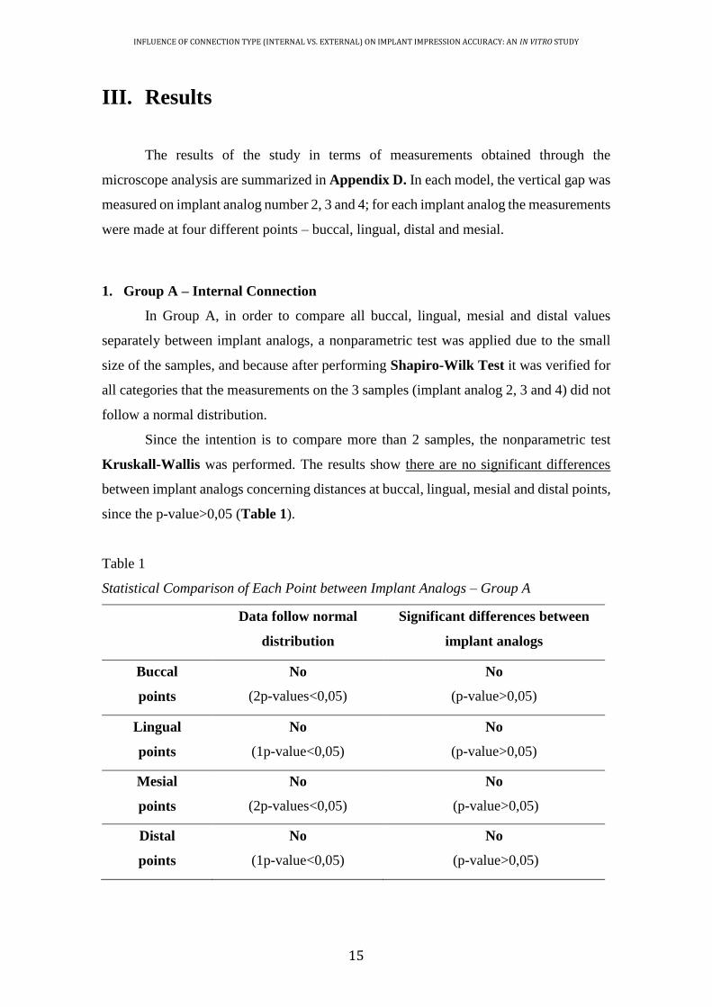
Since the intention is to compare more than 2 samples, the nonparametric test
Kruskall-Wallis was performed. The results show there are no significant differences
between implant analogs concerning distances at buccal, lingual, mesial and distal points,
since the p-value>0,05 (Table 1).
Table 1
Statistical Comparison of Each Point between Implant Analogs – Group A
Data follow normal
distribution
Significant differences between
implant analogs
Buccal
points
No
(2p-values<0,05)
No
(p-value>0,05)
Lingual
points
No
(1p-value<0,05)
No
(p-value>0,05)
Mesial
points
No
(2p-values<0,05)
No
(p-value>0,05)
Distal
points
No
(1p-value<0,05)
No
(p-value>0,05)

INFLUENCE OF CONNECTION TYPE (INTERNAL VS. EXTERNAL) ON IMPLANT IMPRESSION ACCURACY: AN IN VITRO STUDY
16
2. Group B – External Connection
In Group B, in order to compare all buccal, lingual, mesial and distal values
separately between implant analogs, a nonparametric test was applied due to the small
size of the samples, and because after performing Shapiro-Wilk Test it was verified that
all but one (buccal points) did not follow a normal distribution. However, Levene’s Test
determined that the assumption of equal variances was not valid for this category.
Since the intention is to compare more than 2 samples, the nonparametric test
Kruskall-Wallis was performed. The results show there are significant differences
between implant analogs concerning distances at buccal and mesial points, since the p-
value<0,05 (Table 2).
Table 2
Statistical Comparison of Each Point between Implant Analogs – Group B
Data follow normal
distribution
Significant differences between
implant analogs
Buccal
points
Yes
(values>0,05)
Yes
(p-value<0,05)
Lingual
points
No
(1p-value<0,05)
No
(p-value>0,05)
Mesial
points
No
(1p-value<0,05)
Yes
(p-value<0,05)
Distal
points
No
(1p-value<0,05)
No
(p-value>0,05)
With respect to buccal and mesial points, statistically significant differences were
observed between implant analogs 2 and 3 and between implant analogs 2 and 4. It was
verified that the vertical gap on implant analog 2 is significantly lower than the ones on
implant analogs 3 and 4.

INFLUENCE OF CONNECTION TYPE (INTERNAL VS. EXTERNAL) ON IMPLANT IMPRESSION ACCURACY: AN IN VITRO STUDY
17
3. Comparison between Groups
The comparison between Group A and B was performed by analysing each
implant analog/point combination.
After performing Shapiro-Wilk Test, it was verified that the measurements at
each combination did not all follow normal distribution.
When data followed normal distribution, T-student Test (parametric test) was
performed. On the other hand, Mann-Whitney Tests (nonparametric tests) was used if
the values did not come from normal populations.
The results show there are significant differences between internal and external
connections, concerning measurements in all implant/point combinations (Table 3).
Larger gaps were found when the measurements in the stone casts were obtained
from external connection group.
It was concluded that Group B (external connection) presented vertical gaps
statistically higher than the ones verified in Group A (internal connection).
Table 3
Statistical Comparison of Each Combination between Group A and B
Data follow normal
distribution
Significant differences between
implant analogs
Implant 2,
Buccal point
No
(1p-values<0,05)
Yes
(p-value<0,05)
Implant 2,
Lingual point
Yes
(p-values>0,05)
Yes
(p-value<0,05)
Implant 2,
Mesial point
No
(p-values<0,05)
Yes
(p-value<0,05)
Implant 2,
Distal point
Yes
(p-values>0,05)
Yes
(p-value<0,05)
Implant 3,
Buccal point
Yes
(p-values>0,05)
Yes
(p-value<0,05)
Implant 3,
Lingual point
No
(1p-values<0,05)
Yes
(p-value<0,05)
(to be continued)

INFLUENCE OF CONNECTION TYPE (INTERNAL VS. EXTERNAL) ON IMPLANT IMPRESSION ACCURACY: AN IN VITRO STUDY
18
Implant 3,
Mesial point
Yes
(p-values>0,05)
Yes
(p-value<0,05)
Implant 3,
Distal point
Yes
(p-values>0,05)
Yes
(p-value<0,05)
Implant 4,
Buccal point
No
(1p-values<0,05)
Yes
(p-value<0,05)
Implant 4,
Lingual point
No
(p-values<0,05)
Yes
(p-value<0,05)
Implant 4,
Mesial point
No
(1p-values<0,05)
Yes
(p-value<0,05)
Implant 4,
Distal point
No
(p-values<0,05)
Yes
(p-value<0,05)
Table 4
Descriptive Statistics of the Vertical Gap in mm for the Two Groups Tested - Buccal
N Mean Min Max
Internal Connection 30 0,020 0,007 0,061
External connection 30 0,058 0,012 0,155
(continuation)
Mea
sure
men
ts
IC EC
Type of connection
Figure 21. Box-whisker plots of the vertical gap in mm for the two groups tested –
buccal points

INFLUENCE OF CONNECTION TYPE (INTERNAL VS. EXTERNAL) ON IMPLANT IMPRESSION ACCURACY: AN IN VITRO STUDY
19
Table 5
Descriptive Statistics of the Vertical Gap in mm for the Two Groups Tested - Lingual
Table 6
Descriptive Statistics of the Vertical Gap in mm for the Two Groups Tested - Mesial
N Mean Min Max
Internal Connection 30 0,017 0,005 0,074
External connection 30 0,056 0,012 0,156
N Mean Min Max
Internal Connection 30 0,017 0,006 0,066
External connection 30 0,053 0,011 0,133
Figure 22. Box-whisker plots of the vertical gap in mm for the two groups tested –
lingual points
Mea
sure
men
ts
IC EC
Type of connection
Mea
sure
men
ts
IC EC
Type of connection
Figure 23. Box-whisker plots of the vertical gap in mm for the two groups tested –
mesial points

INFLUENCE OF CONNECTION TYPE (INTERNAL VS. EXTERNAL) ON IMPLANT IMPRESSION ACCURACY: AN IN VITRO STUDY
20
Table 7
Descriptive Statistics of the Vertical Gap in mm for the Two Groups Tested - Distal
N Mean Min Max
Internal Connection 30 0,019 0,007 0,095
External connection 30 0,053 0,015 0,176 M
easu
rem
ents
IC EC
Type of connection
Figure 24. Box-whisker plots of the vertical gap in mm for the two groups tested –
distal points
INFLUENCE OF CONNECTION TYPE (INTERNAL VS. EXTERNAL) ON IMPLANT IMPRESSION ACCURACY: AN IN VITRO STUDY
21
IV. Discussion
The results suggest that internal connection implants (Group A) yielded
significantly more accurate impressions than external connection implants (Group B).
The null hypothesis that there would be no significant differences on the accuracy
of implant impressions produced by tested implant connection types was rejected. Since
there are no previously published in vivo or in vitro studies evaluating the influence of
the same factor (implant connection type), the conclusion of this investigation cannot be
compared.
Working casts should accurately represent the clinical relationship of the implants
allowing the fabrication of passively-fitting prostheses. Consequently, there will be an
elimination of strain on the supporting implant components and the surrounding bone
(Del'Acqua et al., 2008). The effect of different factors on the accuracy of implant
impressions has been mainly investigated in vitro resulting in limited clinical data.
Although most authors emphasize that a “passive fit” of a multi-implant
framework cannot be achieved, the amount of misfit and resultant stress that can be
clinically accepted is still unknown (Wenz and Hertrampf, 2008).
The different connection geometry between and within commercially available
implant systems may affect the accuracy of impressions. Several studies have evaluated
the accuracy of impression techniques with external connection implants, but only few
studies have examined the same factor in internal connection implants. The different
results among studies of EC and IC implants are the consequence of employing different
prosthetic connection mechanisms and measurements methods (Mpikos et al., 2012).
There are large differences in the mean values and standard deviations in this
study. In most measurements, the connections showed good mean results, but with great
variations. This fact implies that the same connection does not behave homogenously.
The results can be influenced by the micrometric tolerance inherent in the machining of
the prosthodontic components and by the measurement method employed. Just one screw
was tightened to the framework, leading to amplification of the gap values (Del'Acqua et
al., 2008).
The results obtained are in conformity with the data from the reports by Jemt,
1991 and Tan et al., 1993. The authors suggested that the one-screw test for evaluation of
framework fit showed that vertical discrepancies tend to be magnified at the opposite

INFLUENCE OF CONNECTION TYPE (INTERNAL VS. EXTERNAL) ON IMPLANT IMPRESSION ACCURACY: AN IN VITRO STUDY
22
terminal abutment. The only exception is the mesial point in the external connection
group which showed higher measurements on implant analog number 3 than on number
4. However, these discrepancies are often masked if the distortion occurred in the
negative z-axis direction (Fernandez et al., 2013).
In 1994, Kalus and Bessing developed a rating scale for evaluation of the fit of a
framework. In this study, the prosthesis was seated on abutments and tightened with one
screw in the abutment number 1. The vertical gap between the cylinder and the abutment
number 4 was given a rating using a 4-point scale: 0=no visible discrepancy, 1=slight
discrepancy indicating a clear elevation of the framework with a gap less than 0,5mm, 2=
a moderate discrepancy of approximately 0,5 to 1mm, and 3=pronounced discrepancy
with a gap of clearly more than 1mm. If this classification had been used in the present
study, all the results would have been 0 or 1, since the largest gap value measured for an
analog was 0,176 mm (176 µm). In cases where the fit was 0, a gap between the abutment
and framework would have been detectable only microscopically (Del'Acqua et al.,
2008).
No specific range of acceptable misfit has yet been established (Ma et al., 1997).
However, the significance of passive clinical fit of an implant-supported prosthesis has
been highlighted in the literature to prevent complications (Papaspyridakos et al., 2011).
Experienced operators cannot detect clinically discrepancies of less than 30µm in the fit
of an implant-retained framework on multiple abutments. This figure could serve as a
criterion between acceptable and unacceptable frameworks (Herbst et al., 2000). Jemt,
1991 and May et al,. 1997 suggested that discrepancies on the order of 100 to 150µm fall
within a clinical range of passive fit. Thus, it appears that based on the findings of this
study any of the connection types examined produce clinically acceptable results, if
evidence-based protocols are followed. The lack of any reference value for defining misfit
makes it difficult to recommend any particular type of connection.
The results of this study underline that even with standardized in vitro conditions
the exact spatial reproduction of the implant positions in a working cast is not obtainable.
Thus, the ideal objective is difficult to fully realize clinically because of the potential for
distortion of the stone cast, which is caused by a combination of dimensional errors in the
transfer process of the replicas, and also because framework adaptation may change when
the retaining screws are tightened (Herbst et al., 2000).
It should also be noted that, unlike external-hexagon connections, the internal-
connection configurations adopted by different implant manufacturers are not alike. With

INFLUENCE OF CONNECTION TYPE (INTERNAL VS. EXTERNAL) ON IMPLANT IMPRESSION ACCURACY: AN IN VITRO STUDY
23
respect to the implant-abutment coupling of internal-connection implant systems, many
differences have been described (Goiato et al., 2015). These differences might have a
profound impact on clinical procedures and protocols. Some internal connection
configurations have an intimate fit with the respective impression copings, which can
make the impression more difficult to take and, therefore, may generate a higher degree
of distortion (Gracis et al., 2012).
Implant components displacements can be introduced during the process of
producing a definitive cast. The first is the displacement of each impression coping on
the mating surface of each implant. The difference in rest position between the
components when they are screwed is defined as machining tolerance.(Fernandez et al.,
2013).
Manufacturing variables may contribute to the intimacy of the fit of implant and
prosthetic components: machining tolerances of implant components, materials used in
the manufacturing process, and the resultant physical and mechanical properties of the
components (Martinez-Rus et al., 2013). Machining tolerance differs among different
implant systems, representing an unknown variable in accuracy measurements (Ma et al.,
1997). Herbst et al., 2000 showed that connecting an impression coping or an abutment
replica could introduce more than 30 µm of displacement. Therefore, when the results of
the studies investigating implant impression accuracy are interpreted, the machining
tolerance should be considered as one of the factors affecting accuracy (Martinez-Rus et
al., 2013)
The second factor is the displacement of each impression coping from the
impression technique. Unscrewing the guide pins from the impression copings when the
tray is removed from the mouth/model or screwing the matching abutment replicas in the
impression may cause minor movement and thus influence cast accuracy (Vigolo et al.,
2003).
Paired prosthetic components may be rotationally displaced during connection to
their respective parts. This displacement cannot be controlled by the clinician and lies
within the range of the inherent machining tolerance. Hence, errors occur during the
connection of impression copings to the implants intraorally and to the implant analogs
in the laboratory, respectively (Papaspyridakos et al., 2012).
A possible limitation of the present study is the use of manual torque to tighten
the reference framework to the work casts. A torque driver should be used in order to
apply an even force of 10Ncm.With a higher torque, there would have been a risk of

INFLUENCE OF CONNECTION TYPE (INTERNAL VS. EXTERNAL) ON IMPLANT IMPRESSION ACCURACY: AN IN VITRO STUDY
24
screw fracture, the vertical discrepancy would have been reduced, and there inevitably
would have been transfer of stresses to the implant analogs and screws (Del Acqua et al.,
2010). Nevertheless, dentists in their clinical practice usually apply the method used in
this study.
The methodology of the present study was standardized to allow a careful
evaluation of different types of connection, while isolating other related variables,
particularly those associated with laboratory procedures: setting time, use of direct
technique, machine mixed impression material.
Some authors reported that implant angulation causes distortion of the impression
material on removal. Thus, the greater the divergence between analogs, the more
imprecise the impression will be (Del'Acqua et al., 2008). It should be noted that the
implant analogs in the master casts of this study were parallel to each other and
perpendicular to the surface, which minimized this factor.
None of the prosthesis fabrication methods employed have been able to produce
frameworks with absolute passive fit (Papaspyridakos et al., 2011). A perfect fit occurs
when all the matching surfaces of the implant and framework are in alignment and in
contact without the application of force (Del Acqua et al., 2010). In this study, the lost-
wax technique was used to fabricate the reference bar used throughout the measurements.
It is known that the accuracy of this technique depends on multiple factors, including
waxing technique and alloy behavior (Fernandez et al., 2013). In order to control these
error sources, the position of the implant analogs in the master cast was determined only
after casting the reference framework, attaching the analogs to the respective bar before
pouring the definitive models.
The fact that implant analogs were placed in the same position in both groups
using the transference bar, minimized the differences between them and standardized the
conditions.
In several in vitro studies, master models that were block shape and had flat
impression surfaces were included. However, neither of these can simulate the
deformation that takes place in impression material upon removal, since curved-arch
models were not used (Akalin et al., 2013). In the current study, two master models with
an anatomic shape resembling the edentulous mandible were used.
Accordingly to the literature, the use of polyether or polyvinyl siloxane for direct
multi-implant impressions for edentulous arches produces similarly accurate implant
casts (Chang et al., 2012).

INFLUENCE OF CONNECTION TYPE (INTERNAL VS. EXTERNAL) ON IMPLANT IMPRESSION ACCURACY: AN IN VITRO STUDY
25
Splinting directly impression copings is often used as a technique to eliminate
rotational movement and to take advantage of the stabilization of the impression copings.
However, in this situation, can be seen as an error factor due to multiples variables: type
of material, amount of material and its shrinkage. As an alternative, an impression
material with adequate rigidity was used as recommended (Akalin et al., 2013). When
used by itself, PE simplified the impression procedure, reduced the time required and
minimized the chance of accidental displacement of the direct impression coping when
the replicas were tightened (Del'Acqua et al., 2008).
In assessing the evidence to establish best practices, it is relevant that mixing
techniques may account for the range of reported findings with respect to polyether
performance. The application of the automix system has demonstrated greater control in
polyether material manipulation when compared with manual mixing (Papaspyridakos et
al., 2012).
The impressions were made in a controlled-temperature environment (23ºC± 2ºC)
and no control of the humidity. The manufacturer’s setting time was doubled in order to
compensate for a delayed polymerization reaction at room temperature rather than at
mouth temperature (Del Acqua et al., 2010).
Few articles have evaluated the influence of tray type on the accuracy of implant
impressions. Burns et al. 2003 showed that custom trays produce more precise
impressions than stock trays. Nevertheless, because of the additional time and cost
required to fabricate custom trays, dentists tend to use stock trays that show favorable
results, when correctly chosen. (Del'acqua et al., 2012).
The pouring procedure can alter the analogs’ relationship because of the plaster
expansion (Del'Acqua et al., 2010a). To minimize this factor, some techniques have been
reported: The double-pouring technique minimizes the volumetric expansion of the stone
and has been shown to lead to more accurate die casts. After connection of the implant
analogs to the copings, an initial pour of vacuum-mixed die stone up to the middle of the
analogs is carried out. After 30 minutes, the second pour of die stone is performed
(Papaspyridakos et al., 2012); other option is the latex-tube pouring technique. Tubes are
fitted onto the analogs, and pouring is performed by the conventional technique. After
initial setting (approximately 10 minutes) the latex tubes are remove and a smaller
quantity of dental stone is syringed around each analog (Del'Acqua et al., 2008).
Although none of these techniques have been used in this study, IV dental stone
was employed because of its linear setting expansion of 0,10% at most (Fernandez et al.,

INFLUENCE OF CONNECTION TYPE (INTERNAL VS. EXTERNAL) ON IMPLANT IMPRESSION ACCURACY: AN IN VITRO STUDY
26
2013, Herbst et al., 2000) and vacuum-mixed following manufacturer recommendations.
In this study, microscopy was used to measure the gap width between the metal
framework and the analogs of the respective working cast at selected points. However,
because inaccuracy is expressed in only one dimension, information may be lost
(Martinez-Rus et al., 2013). The imprecisions seen in these vertical measurements may
be enough to demonstrate the complexity of achieving “passive fit”. For further
improvement, more research in this area should be performed to evaluate eventual
tridimensional movements of implant analogs in the working casts.
Further studies are required to fully understand the influence of the connection
type on the accuracy of implant impressions. To corroborate the findings of the present
study, larger samples and another implant systems should be evaluated. Moreover,
knowledge of the machining tolerances for the specific implant systems could be
necessary before making fit measurements (Braian et al., 2014).
Although this investigation indicates that external connection implants produce
significantly more inaccurate impressions comparing with internal connection type,
additional in vivo studies would be helpful to establish the clinical relevance of this
finding. Is also necessary to define the threshold that distinguishes misfit from acceptable
fit (Braian et al., 2014). This information could be useful for clinicians to understand and
respect the level of precision that is needed for implant-supported prostheses on the
implant level.

INFLUENCE OF CONNECTION TYPE (INTERNAL VS. EXTERNAL) ON IMPLANT IMPRESSION ACCURACY: AN IN VITRO STUDY
27
V. Conclusion
Within the limitations of the present laboratory study, the results suggest that
internal connection implants present better results on the accuracy of implant impressions
comparing to external connection implants. Implant-level impressions made on external
connection implants resulted in statistically lower accuracy than the internal connection
group.
Clinical significance: Improved accuracy of implant impressions may be obtained if
internal connection implants are used.
xix
VI. Appendices
APPENDIX A
Implant components, References and Batch Numbers
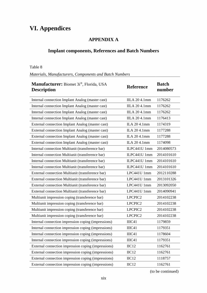
Table 8
Materials, Manufacturers, Components and Batch Numbers
Manufacturer: Biomet 3i®, Florida, USA
Description Reference
Batch
number
Internal connection Implant Analog (master cast) IILA 20 4.1mm 1176262
Internal connection Implant Analog (master cast) IILA 20 4.1mm 1176262
Internal connection Implant Analog (master cast) IILA 20 4.1mm 1176262
Internal connection Implant Analog (master cast) IILA 20 4.1mm 1176413
External connection Implant Analog (master cast) ILA 20 4.1mm 1174319
External connection Implant Analog (master cast) ILA 20 4.1mm 1177288
External connection Implant Analog (master cast) ILA 20 4.1mm 1177288
External connection Implant Analog (master cast) ILA 20 4.1mm 1174098
Internal connection Multiunit (transference bar) ILPC441U 1mm 2014080573
Internal connection Multiunit (transference bar) ILPC441U 1mm 2014101610
Internal connection Multiunit (transference bar) ILPC441U 1mm 2014101610
Internal connection Multiunit (transference bar) ILPC441U 1mm 2014101610
External connection Multiunit (transference bar) LPC441U 1mm 2012110288
External connection Multiunit (transference bar) LPC441U 1mm 2013101326
External connection Multiunit (transference bar) LPC441U 1mm 2013092050
External connection Multiunit (transference bar) LPC441U 1mm 2014090941
Multiunit impression coping (transference bar) LPCPIC2 2014102238
Multiunit impression coping (transference bar) LPCPIC2 2014102238
Multiunit impression coping (transference bar) LPCPIC2 2014102238
Multiunit impression coping (transference bar) LPCPIC2 2014102238
Internal connection impression coping (impressions) IIIC41 1179859
Internal connection impression coping (impressions) IIIC41 1179351
Internal connection impression coping (impressions) IIIC41 1178604
Internal connection impression coping (impressions) IIIC41 1179351
External connection impression coping (impressions) IIC12 1162761
External connection impression coping (impressions) IIC12 1162761
External connection impression coping (impressions) IIC12 1118757
External connection impression coping (impressions) IIC12 1162761
(to be continued)

xx
Description Reference Batch
number
Internal connection Implant Analog (study cast) IILA20 1170466
Internal connection Implant Analog (study cast) IILA20 1170466
Internal connection Implant Analog (study cast) IILA20 1170466
Internal connection Implant Analog (study cast) IILA20 1170466
Internal connection Implant Analog (study cast) IILA20 1175319
Internal connection Implant Analog (study cast) IILA20 1175319
Internal connection Implant Analog (study cast) IILA20 1175319
Internal connection Implant Analog (study cast) IILA20 1175319
Internal connection Implant Analog (study cast) IILA20 1175319
Internal connection Implant Analog (study cast) IILA20 1175319
Internal connection Implant Analog (study cast) IILA20 1175319
Internal connection Implant Analog (study cast) IILA20 1175319
Internal connection Implant Analog (study cast) IILA20 1175319
Internal connection Implant Analog (study cast) IILA20 1175319
Internal connection Implant Analog (study cast) IILA20 1175319
Internal connection Implant Analog (study cast) IILA20 1175319
Internal connection Implant Analog (study cast) IILA20 1175319
Internal connection Implant Analog (study cast) IILA20 1180124
Internal connection Implant Analog (study cast) IILA20 1175319
Internal connection Implant Analog (study cast) IILA20 1175319
External connection Implant Analog (study cast) ILA20 1180076
External connection Implant Analog (study cast) ILA20 1177296
External connection Implant Analog (study cast) ILA20 1177288
External connection Implant Analog (study cast) ILA20 1177288
External connection Implant Analog (study cast) ILA20 1180323
External connection Implant Analog (study cast) ILA20 1180323
External connection Implant Analog (study cast) ILA20 1180323
External connection Implant Analog (study cast) ILA20 1180323
External connection Implant Analog (study cast) ILA20 1180323
External connection Implant Analog (study cast) ILA20 1180323
External connection Implant Analog (study cast) ILA20 1180076
External connection Implant Analog (study cast) ILA20 1180076
External connection Implant Analog (study cast) ILA20 1178095
External connection Implant Analog (study cast) ILA20 1178095
External connection Implant Analog (study cast) ILA20 1178095
External connection Implant Analog (study cast) ILA20 1178095
External connection Implant Analog (study cast) ILA20 1178095
External connection Implant Analog (study cast) ILA20 1178095
External connection Implant Analog (study cast) ILA20 1178095
External connection Implant Analog (study cast) ILA20 1178095
(continuation)

xxi
APPENDIX B
Impregum™ Penta™ – Instructions for use
Table 9
Impregum™ Penta™ use According to the Manufacturer’s Instructions
Manufacturer: 3M ESPE, Seefeld, Germany
Prepare impression trays
For sufficient adhesion, apply a thin layer of Polyether Adhesive to the tray and allow
to dry completely (at least 30-60 sec – 15min drying time are optimal)
Prepare Pentamix™/ Penta Cartridge
With newly filled cartridges, start mixing and extrude and discard the first unevenly
mixed paste prior to the first use for impression taking. Do not use the paste to take
an impression until the color of the paste is homogeneous.
Dosing and Mixing
Dosing and mixing are performed automatically in the Pentamix™.
Times
Model preparation
Prepare a cast from the impression with a sprecialized stone plaster no earlier than 30
min and no later than 14 days after impression taking
Notes
● At temperatures below 18º, the viscosity of the pastes may increase sufficiently to
make mixing in the device difficult. After keeping the pastes at 18ºC for at least one
day, the processability is re-established without compromising quality.
● Store the product at 18-25ºC.
● Direct exposure to sunlight and damp storage conditions may damage the
impression

xxii
APPENDIX C
Mitutoyo Toolmaker’s Microscope – Instructions for measurement
Figure 25. Measurement procedure according to user’s manual - Mitutoyo
Toolmaker’s Microscope.

xxiii
APPENDIX D
Measurements obtained on Microscope Analysis
Table 10
Measurements of the Vertical Gaps in mm – Group A (Internal Connection)
Imp
lan
t An
alo
g 2
Im
pla
nt A
nalo
g 3
Im
pla
nt A
nalo
g 4
B
L
M
D
B
L
M
D
B
L
M
D
I1
0,0
40
0,0
24
0,0
41
0,0
22
0,0
36
0,0
23
0,0
15
0,0
21
0,0
58
0,0
34
0,0
28
0,0
33
I2
0,0
22
0,0
14
0,0
13
0,0
26
0,0
39
0,0
24
0,0
31
0,0
28
0,0
61
0,0
74
0,0
66
0,0
95
I3
0,0
18
0,0
21
0,0
20
0,0
09
0,0
22
0,0
28
0,0
32
0,0
20
0,0
25
0,0
24
0,0
22
0,0
31
I4
0,0
12
0,0
18
0,0
07
0,0
12
0,0
19
0,0
19
0,0
17
0,0
14
0,0
15
0,0
23
0,0
17
0,0
17
I5
0,0
13
0,0
08
0,0
12
0,0
07
0,0
07
0,0
05
0,0
12
0,0
15
0,0
14
0,0
15
0,0
15
0,0
17
I6
0,0
10
0,0
07
0,0
11
0,0
09
0,0
15
0,0
07
0,0
07
0,0
13
0,0
22
0,0
12
0,0
06
0,0
18
I7
0,0
11
0,0
12
0,0
13
0,0
09
0,0
19
0,0
10
0,0
11
0,0
20
0,0
13
0,0
13
0,0
15
0,0
07
I8
0,0
15
0,0
17
0,0
15
0,0
22
0,0
20
0,0
12
0,0
18
0,0
20
0,0
13
0,0
16
0,0
11
0,0
10
I9
0,0
16
0,0
14
0,0
16
0,0
17
0,0
18
0,0
06
0,0
15
0,0
17
0,0
12
0,0
11
0,0
09
0,0
09
I10
0,0
09
0,0
13
0,0
14
0,0
12
0,0
09
0,0
12
0,0
15
0,0
14
0,0
14
0,0
08
0,0
07
0,0
09

xxiv
Table 11
Measurements of the Vertical Gaps in mm – Group B (External Connection)
Imp
lan
t A
nal
og
2
Imp
lan
t A
nal
og
3
Imp
lan
t A
nal
og
4
B
L
M
D
B
L
M
D
B
L
M
D
E1
0
,04
3
0,0
78
0,0
63
0,0
74
0,1
55
0,1
56
0,1
22
0,1
01
0,1
08
0
,05
7
0,0
60
0,0
36
E2
0
,04
0
0,0
33
0,0
25
0,0
33
0,1
08
0,1
44
0,1
16
0,1
05
0,0
89
0
,15
3
0,1
30
0,1
76
E3
0
,03
4
0,0
52
0,0
24
0,0
59
0,1
29
0,0
84
0,1
33
0,1
23
0,0
58
0
,03
4
0,0
33
0,0
40
E4
0
,03
4
0,0
43
0,0
45
0,0
37
0,0
51
0,0
50
0,0
46
0,0
50
0,0
37
0
,02
6
0,0
22
0,0
31
E5
0
,02
7
0,0
35
0,0
24
0,0
37
0,0
80
0,0
53
0,0
81
0,0
70
0,1
29
0
,14
0
0,0
87
0,1
15
E6
0
,02
3
0,0
28
0,0
17
0,0
27
0,0
78
0,0
67
0,0
87
0,0
51
0,0
71
0
,08
2
0,0
83
0,0
85
E7
0
,02
1
0,0
26
0,0
27
0,0
24
0,0
25
0,0
36
0,0
28
0,0
22
0,0
28
0
,03
3
0,0
28
0,0
25
E8
0
,01
7
0,0
16
0,0
28
0,0
15
0,0
69
0,0
25
0,0
65
0,0
32
0,0
47
0
,03
7
0,0
47
0,0
42
E9
0
,01
8
0,0
35
0,0
18
0,0
24
0,0
22
0,0
28
0,0
18
0,0
34
0,0
63
0
,07
2
0,0
57
0,0
51
E1
0
0,0
12
0,0
12
0,0
11
0,0
15
0,0
23
0,0
21
0,0
32
0,0
30
0,1
12
0
,04
8
0,0
41
0,0
47

xxv
VII. References Abdel-Azim T, Zandinejad A, Elathamna E, Lin W and Morton D. The influence of
digital fabrication options on the accuracy of dental implant-based single units and
complete-arch frameworks. The International journal of oral & maxillofacial implants.
2014; 29: 1281-8.
Abduo J and Judge RB. Implications of implant framework misfit: a systematic review
of biomechanical sequelae. The International journal of oral & maxillofacial implants.
2014; 29: 608-21.
Abduo J, Lyons K, Bennani V, Waddell N and Swain M. Fit of screw-retained fixed
implant frameworks fabricated by different methods: a systematic review. The
International journal of prosthodontics. 2011; 24: 207-20.
Aguilar ML, Elias A, Vizcarrondo CE and Psoter WJ. Analysis of three-dimensional
distortion of two impression materials in the transfer of dental implants. The Journal of
prosthetic dentistry. 2010; 103: 202-9.
Akalin ZF, Ozkan YK and Ekerim A. Effects of implant angulation, impression material,
and variation in arch curvature width on implant transfer model accuracy. The
International journal of oral & maxillofacial implants. 2013; 28: 149-57.
Al Quran FA, Rashdan BA, Zomar AA and Weiner S. Passive fit and accuracy of three
dental implant impression techniques. Quintessence international (Berlin, Germany :
1985). 2012; 43: 119-25.
Alikhasi M, Siadat H, Monzavi A and Momen-Heravi F. Three-dimensional accuracy of
implant and abutment level impression techniques: effect on marginal discrepancy. The
Journal of oral implantology. 2011; 37: 649-57.

xxvi
Assif D, Fenton A, Zarb G and Schmitt A. Comparative accuracy of implant impression
procedures. The International journal of periodontics & restorative dentistry. 1992; 12:
112-21.
Assif D, Marshak B and Schmidt A. Accuracy of implant impression techniques. The
International journal of oral & maxillofacial implants. 1996; 11: 216-22.
Assif D, Nissan J, Varsano I and Singer A. Accuracy of implant impression splinted
techniques: effect of splinting material. The International journal of oral & maxillofacial
implants. 1999; 14: 885-8.
Assuncao WG, Filho HG and Zaniquelli O. Evaluation of transfer impressions for
osseointegrated implants at various angulations. Implant dentistry. 2004; 13: 358-66.
Avila ED, Moraes FD, Castanharo SM, Del Acqua MA and Mollo Junior FA. Effect of
Splinting in Accuracy of Two Implant Impression Techniques. The Journal of oral
implantology. 2012.
Baig MR. Accuracy of impressions of multiple implants in the edentulous arch: a
systematic review. The International journal of oral & maxillofacial implants. 2014; 29:
869-80.
Barrett MG, de Rijk WG and Burgess JO. The accuracy of six impression techniques for
osseointegrated implants. Journal of prosthodontics : official journal of the American
College of Prosthodontists. 1993; 2: 75-82.
Bartlett DW, Greenwood R and Howe L. The suitability of head-of-implant and
conventional abutment impression techniques for implant-retained three unit bridges: an
in vitro study. The European journal of prosthodontics and restorative dentistry. 2002;
10: 163-6.
Braian M, De Bruyn H, Fransson H, Christersson C and Wennerberg A. Tolerance
measurements on internal- and external-hexagon implants. The International journal of
oral & maxillofacial implants. 2014; 29: 846-52.

xxvii
Burawi G, Houston F, Byrne D and Claffey N. A comparison of the dimensional accuracy
of the splinted and unsplinted impression techniques for the Bone-Lock implant system.
The Journal of prosthetic dentistry. 1997; 77: 68-75.
Burns J, Palmer R, Howe L and Wilson R. Accuracy of open tray implant impressions:
an in vitro comparison of stock versus custom trays. The Journal of prosthetic dentistry.
2003; 89: 250-5.
Buzayan MM and Yunus NB. Passive Fit in Screw Retained Multi-unit Implant
Prosthesis Understanding and Achieving: A Review of the Literature. Journal of Indian
Prosthodontic Society. 2014; 14: 16-23.
Carr AB. Comparison of impression techniques for a five-implant mandibular model. The
International journal of oral & maxillofacial implants. 1991; 6: 448-55.
Chang WG, Vahidi F, Bae KH and Lim BS. Accuracy of three implant impression
techniques with different impression materials and stones. The International journal of
prosthodontics. 2012; 25: 44-7.
Conrad HJ, Pesun IJ, DeLong R and Hodges JS. Accuracy of two impression techniques
with angulated implants. The Journal of prosthetic dentistry. 2007; 97: 349-56.
Daoudi MF, Setchell DJ and Searson LJ. A laboratory investigation of the accuracy of
two impression techniques for single-tooth implants. The International journal of
prosthodontics. 2001; 14: 152-8.
Del Acqua MA, Chavez AM, Castanharo SM, Compagnoni MA and Mollo Fde A, Jr.
The effect of splint material rigidity in implant impression techniques. The International
journal of oral & maxillofacial implants. 2010; 25: 1153-8.
Del'Acqua MA, Arioli-Filho JN, Compagnoni MA and Mollo Fde A, Jr. Accuracy of
impression and pouring techniques for an implant-supported prosthesis. The International
journal of oral & maxillofacial implants. 2008; 23: 226-36.

xxviii
Del'Acqua MA, Chavez AM, Amaral AL, Compagnoni MA and Mollo Fde A, Jr.
Comparison of impression techniques and materials for an implant-supported prosthesis.
The International journal of oral & maxillofacial implants. 2010; 25: 771-6.
Del'Acqua MA, Chavez AM, Compagnoni MA and Molo Fde A, Jr. Accuracy of
impression techniques for an implant-supported prosthesis. The International journal of
oral & maxillofacial implants. 2010; 25: 715-21.
Del'acqua MA, de Avila ED, Amaral AL, Pinelli LA and de Assis Mollo F, Jr.
Comparison of the accuracy of plastic and metal stock trays for implant impressions. The
International journal of oral & maxillofacial implants. 2012; 27: 544-50.
Fernandez MA, Paez de Mendoza CY, Platt JA, Levon JA, Hovijitra ST and Nimmo A.
A comparative study of the accuracy between plastic and metal impression transfer
copings for implant restorations. Journal of prosthodontics : official journal of the
American College of Prosthodontists. 2013; 22: 367-76.
Ferreira VF, Barboza EP, Gouvea CV, Bianchini GM, Mussallem F and Carvalho WR.
Comparative study of the polyvinyl siloxane technique with resin-splinted transfer
copings used for multiple implant abutment impressions. Implant dentistry. 2012; 21: 72-
6.
Goiato MC, Pellizzer EP, da Silva EV, Bonatto LD and Dos Santos DM. Is the internal
connection more efficient than external connection in mechanical, biological, and
esthetical point of views? A systematic review. Oral and maxillofacial surgery. 2015.
Gracis S, Michalakis K, Vigolo P, Vult von Steyern P, Zwahlen M and Sailer I. Internal
vs. external connections for abutments/reconstructions: a systematic review. Clinical oral
implants research. 2012; 23 Suppl 6: 202-16.
Hariharan R, Shankar C, Rajan M, Baig MR and Azhagarasan NS. Evaluation of accuracy
of multiple dental implant impressions using various splinting materials. The
International journal of oral & maxillofacial implants. 2010; 25: 38-44.

xxix
Herbst D, Nel JC, Driessen CH and Becker PJ. Evaluation of impression accuracy for
osseointegrated implant supported superstructures. The Journal of prosthetic dentistry.
2000; 83: 555-61.
Hsu CC, Millstein PL and Stein RS. A comparative analysis of the accuracy of implant
transfer techniques. The Journal of prosthetic dentistry. 1993; 69: 588-93.
Humphries RM, Yaman P and Bloem TJ. The accuracy of implant master casts
constructed from transfer impressions. The International journal of oral & maxillofacial
implants. 1990; 5: 331-6.
Jemt T. Failures and complications in 391 consecutively inserted fixed prostheses
supported by Branemark implants in edentulous jaws: a study of treatment from the time
of prosthesis placement to the first annual checkup. The International journal of oral &
maxillofacial implants. 1991; 6: 270-6.
Kallus T and Bessing C. Loose gold screws frequently occur in full-arch fixed prostheses
supported by osseointegrated implants after 5 years. The International journal of oral &
maxillofacial implants. 1994; 9: 169-78.
Kim S, Nicholls JI, Han CH and Lee KW. Displacement of implant components from
impressions to definitive casts. The International journal of oral & maxillofacial
implants. 2006; 21: 747-55.
Lee H, Ercoli C, Funkenbusch PD and Feng C. Effect of subgingival depth of implant
placement on the dimensional accuracy of the implant impression: an in vitro study. The
Journal of prosthetic dentistry. 2008; 99: 107-13.
Lee H, So JS, Hochstedler JL and Ercoli C. The accuracy of implant impressions: a
systematic review. The Journal of prosthetic dentistry. 2008; 100: 285-91.
Lee SJ and Cho SB. Accuracy of five implant impression technique: effect of splinting
materials and methods. The journal of advanced prosthodontics. 2011; 3: 177-85.

xxx
Ma T, Nicholls JI and Rubenstein JE. Tolerance measurements of various implant
components. The International journal of oral & maxillofacial implants. 1997; 12: 371-
5.
Martinez-Rus F, Garcia C, Santamaria A, Ozcan M and Pradies G. Accuracy of definitive
casts using 4 implant-level impression techniques in a scenario of multi-implant system
with different implant angulations and subgingival alignment levels. Implant dentistry.
2013; 22: 268-76.
May KB, Edge MJ, Russell MM, Razzoog ME and Lang BR. The precision of fit at the
implant prosthodontic interface. The Journal of prosthetic dentistry. 1997; 77: 497-502.
Moreira AH, Rodrigues NF, Pinho AC, Fonseca JC and Vilaca JL. Accuracy Comparison
of Implant Impression Techniques: A Systematic Review. Clinical implant dentistry and
related research. 2015.
Mostafa TM, Elgendy MN, Kashef NA and Halim MM. Evaluation of the precision of
three implant transfer impression techniques using two elastomeric impression materials.
The International journal of prosthodontics. 2010; 23: 525-8.
Mpikos P, Kafantaris N, Tortopidis D, Galanis C, Kaisarlis G and Koidis P. The effect of
impression technique and implant angulation on the impression accuracy of external- and
internal-connection implants. The International journal of oral & maxillofacial implants.
2012; 27: 1422-8.
Naconecy MM, Teixeira ER, Shinkai RS, Frasca LC and Cervieri A. Evaluation of the
accuracy of 3 transfer techniques for implant-supported prostheses with multiple
abutments. The International journal of oral & maxillofacial implants. 2004; 19: 192-8.
Ongul D, Gokcen-Rohlig B, Sermet B and Keskin H. A comparative analysis of the
accuracy of different direct impression techniques for multiple implants. Australian
dental journal. 2012; 57: 184-9.

xxxi
Ortorp A, Jemt T and Back T. Photogrammetry and conventional impressions for
recording implant positions: a comparative laboratory study. Clinical implant dentistry
and related research. 2005; 7: 43-50.
Papaspyridakos P, Benic GI, Hogsett VL, White GS, Lal K and Gallucci GO. Accuracy
of implant casts generated with splinted and non-splinted impression techniques for
edentulous patients: an optical scanning study. Clinical oral implants research. 2012; 23:
676-81.
Papaspyridakos P, Chen CJ, Gallucci GO, Doukoudakis A, Weber HP and Chronopoulos
V. Accuracy of implant impressions for partially and completely edentulous patients: a
systematic review. The International journal of oral & maxillofacial implants. 2014; 29:
836-45.
Papaspyridakos P, Gallucci GO, Chen CJ, Hanssen S, Naert I and Vandenberghe B.
Digital versus conventional implant impressions for edentulous patients: accuracy
outcomes. Clinical oral implants research. 2015.
Papaspyridakos P, Lal K, White GS, Weber HP and Gallucci GO. Effect of splinted and
nonsplinted impression techniques on the accuracy of fit of fixed implant prostheses in
edentulous patients: a comparative study. The International journal of oral &
maxillofacial implants. 2011; 26: 1267-72.
Phillips KM, Nicholls JI, Ma T and Rubenstein JE. The accuracy of three implant
impression techniques: a three-dimensional analysis. The International journal of oral &
maxillofacial implants. 1994; 9: 533-40.
Rashidan N, Alikhasi M, Samadizadeh S, Beyabanaki E and Kharazifard MJ. Accuracy
of implant impressions with different impression coping types and shapes. Clinical
implant dentistry and related research. 2012; 14: 218-25.
Simeone P, Valentini PP, Pizzoferrato R and Scudieri F. Dimensional accuracy of pickup
implant impression: an in vitro comparison of novel modular versus standard custom
trays. The International journal of oral & maxillofacial implants. 2011; 26: 538-46.

xxxii
Sorrentino R, Gherlone EF, Calesini G and Zarone F. Effect of implant angulation,
connection length, and impression material on the dimensional accuracy of implant
impressions: an in vitro comparative study. Clinical implant dentistry and related
research. 2010; 12 Suppl 1: e63-76.
Spector MR, Donovan TE and Nicholls JI. An evaluation of impression techniques for
osseointegrated implants. The Journal of prosthetic dentistry. 1990; 63: 444-7.
Stimmelmayr M, Erdelt K, Guth JF, Happe A and Beuer F. Evaluation of impression
accuracy for a four-implant mandibular model--a digital approach. Clinical oral
investigations. 2012; 16: 1137-42.
Stimmelmayr M, Guth JF, Erdelt K, Happe A, Schlee M and Beuer F. Clinical study
evaluating the discrepancy of two different impression techniques of four implants in an
edentulous jaw. Clinical oral investigations. 2013; 17: 1929-35.
Tan KB, Rubenstein JE, Nicholls JI and Yuodelis RA. Three-dimensional analysis of the
casting accuracy of one-piece, osseointegrated implant-retained prostheses. The
International journal of prosthodontics. 1993; 6: 346-63.
Vigolo P, Fonzi F, Majzoub Z and Cordioli G. An evaluation of impression techniques
for multiple internal connection implant prostheses. The Journal of prosthetic dentistry.
2004; 92: 470-6.
Vigolo P, Majzoub Z and Cordioli G. Evaluation of the accuracy of three techniques used
for multiple implant abutment impressions. The Journal of prosthetic dentistry. 2003; 89:
186-92.
Wee AG. Comparison of impression materials for direct multi-implant impressions. The
Journal of prosthetic dentistry. 2000; 83: 323-31.

xxxiii
Wenz HJ and Hertrampf K. Accuracy of impressions and casts using different implant
impression techniques in a multi-implant system with an internal hex connection. The
International journal of oral & maxillofacial implants. 2008; 23: 39-47.