university of birmingham additive manufacturing for
TRANSCRIPT
University of Birmingham
Additive manufacturing for quantum technologiesVovrosh, Jamie; Voulazeris, Georgios; Petrov, Plamen; Zou, Ji; Gaber, Youssef; Benn, Laura;Woolger, David; Attallah, Moataz M.; Boyer, Vincent; Bongs, Kai; Holynski, Michael
Citation for published version (Harvard):Vovrosh, J, Voulazeris, G, Petrov, P, Zou, J, Gaber, Y, Benn, L, Woolger, D, Attallah, MM, Boyer, V, Bongs, K &Holynski, M, Additive manufacturing for quantum technologies, 2017, Web publication/site, arXiv.
Link to publication on Research at Birmingham portal
General rightsUnless a licence is specified above, all rights (including copyright and moral rights) in this document are retained by the authors and/or thecopyright holders. The express permission of the copyright holder must be obtained for any use of this material other than for purposespermitted by law.
•Users may freely distribute the URL that is used to identify this publication.•Users may download and/or print one copy of the publication from the University of Birmingham research portal for the purpose of privatestudy or non-commercial research.•User may use extracts from the document in line with the concept of ‘fair dealing’ under the Copyright, Designs and Patents Act 1988 (?)•Users may not further distribute the material nor use it for the purposes of commercial gain.
Where a licence is displayed above, please note the terms and conditions of the licence govern your use of this document.
When citing, please reference the published version.
Take down policyWhile the University of Birmingham exercises care and attention in making items available there are rare occasions when an item has beenuploaded in error or has been deemed to be commercially or otherwise sensitive.
If you believe that this is the case for this document, please contact [email protected] providing details and we will remove access tothe work immediately and investigate.
Download date: 21. Mar. 2022

Additive manufacturing for quantum technologiesJamie Vovrosh1, Georgios Voulazeris1,3, Plamen Petrov1, Ji Zou2, Youssef Gaber2, LauraBenn3, David Woolger3, Moataz M. Attallah2, Vincent Boyer2, Kai Bongs1, and MichaelHolynski1,*
1School of Physics and Astronomy, University of Birmingham, Birmingham, B15 2TT, UK.2School of Metallurgy and Materials, University of Birmingham, Birmingham, B15 2TT, UK3Magnetic Shields Limited, Staplehurst, UK*[email protected]
ABSTRACT
Recent advances in the understanding and control of quantum technologies, such as those based on cold atoms, haveresulted in devices with extraordinary metrological sensitivities. To realise this potential outside of a lab environment the size,weight and power consumption need to be reduced. Here we demonstrate the use of laser powder bed fusion, an additivemanufacturing technique, as a production technique for the components that make up quantum sensors. As a demonstrationwe have constructed two key components using additive manufacturing, namely magnetic shielding and vacuum chambers.The initial prototypes for magnetic shields show shielding factors within a factor of 3 of conventional approaches. The vacuumdemonstrator device shows that 3D-printed titanium structures are suitable for use as vacuum chambers, with the test systemreaching base pressures of 5±0.5×10⁻¹⁰ mbar, and showing an outgassing rate indistinguishable from a commercial ConFlatflange in this pressure regime. These demonstrations show considerable promise for the use of additive manufacturing for coldatom based quantum technologies, in future enabling improved integrated structures, allowing for the reduction in size, weightand assembly complexity.
IntroductionQuantum technologies utilising atom clouds are highly promising tools for creating ever more sensitive devices with applicationsin a vast array of areas ranging from geophysical type applications1, 2 to satellite independent navigation3. The exceptionalperformance of lab based systems4–6 has lead to recent work focused on transforming lab based atomic systems into compacttransportable versions7–10. To produce ever more compact and transportable devices the latest advances in micro-manufacturingtechnology are being used including waveguide writing11 and reactive ion beam etching12. Using these manufacturing methodshas allowed for the miniaturisation of quantum technologies such as integrated atom chip based systems13, 14.
An emerging technology capable of allowing further minaturisation of quantum technology is additive manufacturing, suchas 3D-printing. The freedom of design offered during production by 3D-printing allows for rapid development of complex,individually bespoke components and the potential to tune material properties during production. The focus of 3D-printingtechnologies thus far has been on magnetic field generation15, 16, while little attention has been given to environmental isolation.Here we report on two demonstrators of crucial environmental isolation technologies needed for the realisation of portable andcompact quantum technologies developed with 3D-printing, namely magnetic shielding and vacuum components.
Magnetic shielding is an essential component of atom based quantum technologies necessary to provide a suitable magneticenvironment and enable sensitive measurements. Currently the best available materials for magnetic shielding are soft magneticalloys, such as mu-Metal17. Despite mu-metal shields being widely used, they are characterised by a relatively high weight andthe inflexibility to adapt to more complex geometries, due to manufacturing limitations. While simple shapes such as cylinderscan be easily manufactured, linking shields together without loss of performance is challenging18. Existing shielding is thusheavy and bulky, limiting the advancement of quantum technology towards portable and miniaturised systems. The majority ofproduction is currently realised through hand machining in workshops which limits the ability to create complicated geometries.By using 3D-printing in contrast it is possible to design bespoke complex shielding for each application. However to achievethe best possible magnetic shields the additive process used to create the shields need to be optimised to reduce cracking andporosity in the printed structure, which reduces the effectiveness of the magnetic shields. Combining this with post processingof the 3D-printed structure, the ability to produce magnetic shields with complex compact and light weight geometries closer tothe structure to be shielded should be realised.
Vacuum technology is another prominent component of quantum technology systems, used to isolate atoms from backgroundgasses. At lower pressures the longer measurement times can be achieved without decoherence19. For compact quantum
arX
iv:1
710.
0827
9v1
[ph
ysic
s.ap
p-ph
] 1
9 O
ct 2
017
sensors it is ideal that ultra high vacuum environments are achieved and maintained over long time periods. Since 3D-printingis an additive process, it is possible that small voids and leak channels can form in the material during the printing process.These voids could trap gases which would later vent slowly into the vacuum, making the part unsuitable for ultrahigh vacuumenvironments20. Selection of the material which components are made out of has been shown to reduce these issues in 3D-printed components inside vacuums21. Here we show that by optimising the 3D-printing parameters and materials, 3D-printingtechniques can be used to produce vacuum components. The production of 3D-printed vacuum parts allows for the time andcost to build complicated, specialised geometries to be drastically reduced.
Here for the first time we report on the design, manufacture and characterisation of both 3D-printed magnetic shieldingand vacuum flange demonstrator devices. We compare the performance of these demonstrator devices against an equivalenttraditionally produced component to evaluate the performance of the 3D-printed equivalent.
Results
Magnetic Shielding
A)
B)
56 mm
78mm
28 mm
56 mm 50 mm
78 mm
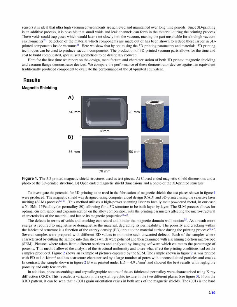
Figure 1. The 3D-printed magnetic shield structures used as test pieces. A) Closed ended magnetic shield dimensions and aphoto of the 3D-printed structure. B) Open ended magnetic shield dimensions and a photo of the 3D-printed structure.
To investigate the potential for 3D-printing to be used in the fabrication of magnetic shields the test pieces shown in figure 1were produced. The magnetic shield was designed using computer aided design (CAD) and 3D-printed using the selective lasermelting (SLM) process22, 23. This method utilises a high-power scanning laser to locally melt powdered metal, in our casea Ni-5Mo-15Fe alloy (or permalloy-80), allowing for a 3D structure to be built layer by layer. The SLM process allows foroptimal customisation and experimentation on the alloy composition, with the printing parameters affecting the micro-structuralcharacteristics of the material, and hence its magnetic properties24, 25.
The defects in terms of voids and cracking can retard and hinder the magnetic domain wall motion25. As a result moreenergy is required to magnetise or demagnetise the material, degrading its permeability. The porosity and cracking withinthe fabricated structure is a function of the energy density (ED) input to the material surface during the printing process26, 27.Several samples were prepared with different ED values to minimise such unwanted defects. Each of the samples wherecharacterised by cutting the sample into thin slices which were polished and then examined with a scanning electron microscope(SEM). Pictures where taken from different sections and analysed by imaging software which estimates the percentage ofporosity. This method allowed the analysis of the structural uniformity and to see what effect the printing conditions had on thesamples produced. Figure 2 shows an example of pictures captured by the SEM. The sample shown in figure 2 A was printedwith ED = 1.4 J/mm2 and has a structure characterised by a large number of pores with unconsolidated particles and cracks.In contrast, the sample shown in figure 2 B was printed under ED = 4.9 J/mm2 and showed the best results with negligibleporosity and only few cracks.
In addition, phase assemblage and crystallographic texture of the as-fabricated permalloy were characterised using X-raydiffraction (XRD). This revealed a variation in the crystallographic texture in the two different planes (see figure 3). From theXRD pattern, it can be seen that a (001) grain orientation exists in both axes of the magnetic shields. The (001) is the hard
2/10

500 μm
B)
A)
500 μm
Figure 2. Pictures captured by a SEM on different 3D-printed samples revealing structural defects. A) Sample printed undernon-optimal parameters with ED = 1.4 J/mm2 and shows a large number of defects. B) Sample produced with under optimumparameters with ED = 4.9 J/mm2 showing minimal defects.
axis for an Ni enriched alloy, such as the permalloy-80 used to create the magnetic shields. The presence of the (001) grainorientation will have a negative impact on the shielding factor of the shields28. Further optimisation of the SLM process usedmay be able to reduce the percentage of the material with the (001) grain orientation. However the crystallographic property’slook favourable in the transverse direction (XY-plane) which is the plane of interest for these experiments.
To characterise the magnetic shielding performance the amplitude ratio of the magnetic field without the presence of theshield Bout , over the residual field measured at the same point after the shield installation Bin is used. This ratio is knownas the shielding factor St = Bout/Bin, where the subscript t indicates the magnetising field orientation along the transverseshield axis. The magnetic shielding factors from both before and after annealing the test pieces, when using a test field of 50µT magnetic field, can be seen in figures 4 A and 4 B. It can be seen that the maximum magnetic shielding factors obtainedbefore annealing for the open and closed pieces were 14±0.1 and 30±0.3 respectively. These maximum values were thenincreased significantly with the application of the annealing process for both the open and closed pieces to 206± 13 and542±64 respectively.
To see whether further treatment could improve the performance, heat treatment under hot isostatic pressing (HIP) was alsoinvestigated. HIP is often performed during manufacture to release internal stresses within the materials used29. The effect ofapplying HIP treatment prior to annealing on a 3D-printed test piece can be seen in figure 4 C. The details of the HIP cycleparameters can be found in the Methods section. It can be seen that the shielding factor increased by a factor of 7 after the HIPtreatment, reaching a value of St ≈ 150 at the cylinder central region. This factor was then doubled after annealing, reaching ashielding factor of St ≈ 260, approximately at the centre of the shield. As can be seen in figure 4 B the test piece which didnot undergo HIP treatment demonstrated very similar performance, suggesting that although HIP as an intermediate step isimportant for optimising structural integrity it might not be necessary for magnetic shielding applications. In that case, opting tofollow only one heat treatment instead of two, could reduce potential production cost in the future. Alternatively, it is possible
3/10

Figure 3. Comparison of the results from XRD tests on the unprocessed permalloy-80 powder and the sample produced withED = 4.9 J/mm2 along the XY and YZ-plane, respectively. The z axis is defined as the vertical axis of the sample. Each peakrepresents the intensity of the detected regions with the same crystallographic orientation. Although both phases are almostequally distributed on the YZ-plane, the (200) orientation dominates in the XY plane.
that further optimisation of the HIP parameters may also lead to further improvements.The performance of the 3D-printed open ended test piece was compared to that of a mu-metal control shield with the same
dimensions, fabricated using standard techniques. These were both processed using the same procedure, which is optimisedbased upon the mu-metal shield. A comparison of the magnetic shielding factors can be seen in figure 4 D. The shielding factorof the test piece is found to be a factor of 2.75 smaller than the control shield, showing that 3D-printing has promise in thecreation of magnetic shields. In particular, this would be of benefit in the creation of complex geometries, which may allow forsubstantial geometric improvements in the shield design to enable considerably better shielding per unit weight. Furthermore,optimisation of the fabrication and post-processing may yield further improvements.
Vacuum componentsMany materials that are commonly used in ultra high vacuum (UHV) are also 3D-printable materials, such as silver, gold,stainless steel and titanium. The low vapour pressures of metals make them ideal for vacuum applications, however this is notthe only consideration in determining UHV compatibility. The processes used in 3D-printing metals could potentially give riseto several adverse effects, such as introducing trapped gases resulting in virtual leaks, and micro-leak channels. In addition,the resulting surface roughness and porosity of the printed part can greatly increase effective surface area and therefore outgassing load. These problems must be ruled out if 3D-printed materials are to be used to create UHV systems. Additionally it isimportant to determine if any special surface cleaning or passivation steps are necessary before 3D-printed vacuum parts canbe used. Currently the vacuum compatibility of 3D-printed materials has been shown for small components that sit inside avacuum system, such as for Al-Si10-Mg, titanium and silver16, 21, 30. However here we will show that 3D-printed parts can beused to construct vacuum chambers, through acting as the vacuum wall and sealing to peripheral components.
The 3D-printed part was designed using CAD software and titanium (Ti) was chosen as it is a common vacuum materialand readily 3D-printed. Furthermore, its non-magnetic properties are well-suited to cold atomic physics. The test piece wasprinted using direct metal laser sintering of alloy Ti-6Al-4V. The surface face of the test piece was smoothed with a millingmachine to allow for indium sealing to the system and cleaned ultrasonically with acetone. The inside of the 3D-printed partwas not smoothed. When sealed to a vacuum the seal was done by indium wire with 1 mm diameter. The test piece and themethod of sealing to a DN40CF can be seen in figure 5.
The experimental set up used to test the piece in comparison to a control flange produced by traditional methods (CFB70,MDC Vacuum LDC made of 304 stainless steel) can be seen in figure 6. The set up consists of two branches which can beindependently sealed off from each other and the rest of the chamber. The test branch contains the test piece, while the referencebranch contains the control flange. The setup is pumped by an ion pump and the pumping speed for the two branches is thesame due to the same conductance to the ion pump.
Pumping was provided by a triode configuration ion pump (Agilent technologies, Vaclon Plus 20 StarCell) and the pressurewas measured using a cold cathode gauge (Pfeiffer, IKR 270). Moderate bake-out temperatures were achieved using heatertapes (SWH Series, Omega UK) and adjustable transformers (EA-STT 2000B-4.5A, Farnell), providing a stable temperatureof ∼ 130 ◦C for 160 hours. The analogue output from the gauge controller was recorded every 0.5 s. The pressure duringbakeout and cooling down can be seen in figure 7. The data has been smoothed using a median filter to remove noise spikes.
4/10
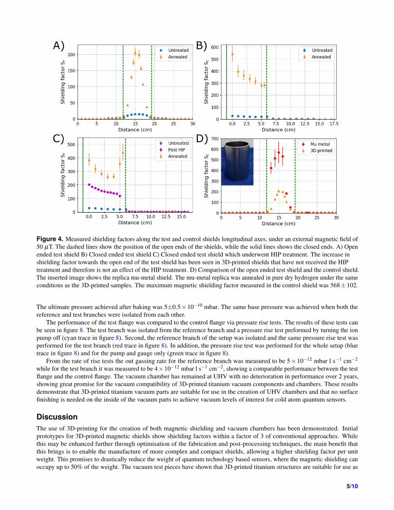
Figure 4. Measured shielding factors along the test and control shields longitudinal axes, under an external magnetic field of50 µT. The dashed lines show the position of the open ends of the shields, while the solid lines shows the closed ends. A) Openended test shield B) Closed ended test shield C) Closed ended test shield which underwent HIP treatment. The increase inshielding factor towards the open end of the test shield has been seen in 3D-printed shields that have not received the HIPtreatment and therefore is not an effect of the HIP treatment. D) Comparison of the open ended test shield and the control shield.The inserted image shows the replica mu-metal shield. The mu-metal replica was annealed in pure dry hydrogen under the sameconditions as the 3D-printed samples. The maximum magnetic shielding factor measured in the control shield was 568±102.
The ultimate pressure achieved after baking was 5±0.5×10⁻¹⁰ mbar. The same base pressure was achieved when both thereference and test branches were isolated from each other.
The performance of the test flange was compared to the control flange via pressure rise tests. The results of these tests canbe seen in figure 8. The test branch was isolated from the reference branch and a pressure rise test preformed by turning the ionpump off (cyan trace in figure 8). Second, the reference branch of the setup was isolated and the same pressure rise test wasperformed for the test branch (red trace in figure 8). In addition, the pressure rise test was performed for the whole setup (bluetrace in figure 8) and for the pump and gauge only (green trace in figure 8).
From the rate of rise tests the out gassing rate for the reference branch was measured to be 5×10⁻¹² mbar l s−1 cm−2
while for the test branch it was measured to be 4×10⁻¹² mbar l s−1 cm−2, showing a comparable performance between the testflange and the control flange. The vacuum chamber has remained at UHV with no deterioration in performance over 2 years,showing great promise for the vacuum compatibility of 3D-printed titanium vacuum components and chambers. These resultsdemonstrate that 3D-printed titanium vacuum parts are suitable for use in the creation of UHV chambers and that no surfacefinishing is needed on the inside of the vacuum parts to achieve vacuum levels of interest for cold atom quantum sensors.
DiscussionThe use of 3D-printing for the creation of both magnetic shielding and vacuum chambers has been demonstrated. Initialprototypes for 3D-printed magnetic shields show shielding factors within a factor of 3 of conventional approaches. Whilethis may be enhanced further through optimisation of the fabrication and post-processing techniques, the main benefit thatthis brings is to enable the manufacture of more complex and compact shields, allowing a higher shielding factor per unitweight. This promises to drastically reduce the weight of quantum technology based sensors, where the magnetic shielding canoccupy up to 50% of the weight. The vacuum test pieces have shown that 3D-printed titanium structures are suitable for use as
5/10

A)
Ti piece
DN40 CF Flange
In wire seal
M6 bolts
M6 washers
B)
DN40 CF Flange
Ti piece
Figure 5. A) Digital render of the vacuum flange structure with components for vacuum sealing. The test piece was designedwith a top hat profile with a diameter of 70mm and indium sealed onto a stainless steel flange. The stainless steel flange hadbore holes of 30mm and 6 M6 tapped holes to apply pressure to the indium seal. Once sealed the DN40CF flange is attached tothe chamber using a standard copper gasket. The holes in test piece the are compatible with a DN40CF flange. B) The DN40CF flange and test piece prior to Assembly.
vacuum walls, as a sealing surface, and by association chambers. The test system reached base pressures of 5±0.5×10⁻¹⁰
mbar, and demonstrated an out gassing rate indistinguishable from a commercial ConFlat flange. This has been achievedwithout post-processing or surface finishing of the internal walls. Combining the ability to 3D-print both magnetic shieldingand vacuum systems will allow for a step change in the compactness and weight of quantum devices and facilitate greatersystems integration. This also has the potential to benefit wider applications, in particular in sectors which require low weightshielding such as aerospace.
Methods
Magnetic Shielding Production detailsThe powder used to produce the magnetic shielding samples presented here was a Ni-5Mo-15Fe alloy (or permalloy-80),purchased from the TLS Technik company. All testing samples were produced on a 400-W powered Concept Laser M2 Cusingsystem, operating in an argon atmosphere using gas atomised powders in the size range 15-53 microns. Once printed specialheat treatments are used to enhance the physical properties of printed material. Two different types of heat treatment wereapplied to the samples produced by SLM manufacturing of permalloy-80.
The process parameters for the first method, hot isostatic pressing (HIP), are shown in the time–temperature diagram infigure 9. The selected cycle for this design of experiments is typically used for 3D-printed materials of similar composition,predominantly to eliminate structural defects.
The second method is annealing in pure dry hydrogen, which was undertaken at the Magnetic Shields Ltd. facilities. Thiscycle is used commercially by the company for bringing mu-metal shields to optimum magnetic performance as the final stepafter manufacturing. The relevant parameters are shown in figure 10.
Magnetic Shielding MeasurementsIn preparation for testing the shielding performance, all the shields were demagnetised after production using a small degausser(Eclipse Magnetics, DA955 demagnetiser). The measurements of the magnetic shielding factors where performed using aStefan Mayer 1-axis Fluxgate Magnetometer Fluxmaster which was fixed at the centre of the coils, while the shield was movedaround it. This was achieved by a rail base that allowed the shield to slide from the one side to the other, through the coils,
6/10

Test branch
Reference branch
Test flange
Control flange
Vacuumgauge
Pump
Gatevalve
Gatevalve
Figure 6. The experimental set up for testing the performance of the 3D-printed flange compared to a commercial equivalent.
encompassing the sensor. The applied magnetic field strength in all experiments was 50 µT applied in the transverse orientationconfiguration.
3D-printed flange production detailsThe 3D-printed test flange was prepared for printing using Solid Works and i.materialise.
References1. Boddice, D., Metje, N. & Tuckwell, G. Capability assessment and challenges for quantum technology grav-
ity sensors for near surface terrestrial geophysical surveying. J. Appl. Geophys. 146, 149 – 159 (2017). DOIhttps://doi.org/10.1016/j.jappgeo.2017.09.018.
2. Dowling, J. P. & Milburn, G. J. Quantum technology: the second quantum revolution. Philos. Transactions Royal Soc.Lond. A: Math. Phys. Eng. Sci. 361, 1655–1674 (2003).
3. Keil, M. et al. Fifteen years of cold matter on the atom chip: promise, realizations, and prospects. J. modern optics 63,1840–1885 (2016).
4. Kovachy, T. et al. Quantum superposition at the half-metre scale. Nat. 528, 530–533 (2015).
5. Bloom, B. J. et al. An optical lattice clock with accuracy and stability at the 10-18 level. Nat. 506, 71–75.
6. Sander, T. H. et al. Magnetoencephalography with a chip-scale atomic magnetometer. Biomed. Opt. Express 3, 981–990(2012). DOI 10.1364/BOE.3.000981.
7. Hinton, A. et al. A portable magneto-optical trap with prospects for atom interferometry in civil engineering. Phil. Trans.R. Soc. A 375, 20160238 (2017).
8. Wu, B. et al. The investigation of a µgal-level cold atom gravimeter for field applications. Metrol. 51, 452 (2014).
9. Hauth, M. et al. First gravity measurements using the mobile atom interferometer gain. Appl. Phys. B 113, 49–55 (2013).
10. Menoret, V. et al. Dual-wavelength laser source for onboard atom interferometry. Opt. Lett. 36, 4128–4130 (2011).
11. Politi, A., Cryan, M. J., Rarity, J. G., Yu, S. & O’brien, J. L. Silica-on-silicon waveguide quantum circuits. Sci. 320,646–649 (2008).
12. Sewell, R. et al. Atom chip for bec interferometry. J. Phys. B: At. Mol. Opt. Phys. 43, 051003 (2010).
7/10

Figure 7. Chamber pressure of the entire system vs time, after equalisation at a bake-out temperature of ∼ 130◦C. After 160hours the bake out ended and the temperature of the system returned to room temperature (∼ 21◦C), and the pressure in thechamber reduced by roughly an order of magnitude.
Figure 8. Rate of rise curves for the different sections of the vacuum system. The pressure before the rate of rise curve is notrepresentative of the minimum achievable pressures but instead of the pressure in the chamber before the test was carried out.
13. Muntinga, H. et al. Interferometry with bose-einstein condensates in microgravity. Phys. Rev. Lett. 110, 093602 (2013).DOI 10.1103/PhysRevLett.110.093602.
14. Imhof, E. et al. Two-dimensional grating magneto-optical trap. Phys. Rev. A 96, 033636 (2017). DOI 10.1103/Phys-RevA.96.033636.
15. Zhou, Y. et al. Design of magneto-optical traps for additive manufacture by 3d printing. arXiv preprint arXiv:1704.00430(2017).
16. Saint, R. et al. 3d-printed components for quantum devices. arXiv preprint arXiv:1704.01813 (2017).
17. Tong, X. C. Advanced materials and design for electromagnetic interference shielding (CRC press, 2016).
18. Dickerson, S. et al. A high-performance magnetic shield with large length-to-diameter ratio. Rev. Sci. Instruments 83,065108 (2012). DOI 10.1063/1.4720943.
19. Hornberger, K. et al. Collisional decoherence observed in matter wave interferometry. Phys. Rev. Lett. 90, 160401 (2003).DOI 10.1103/PhysRevLett.90.160401.
20. Das, S., Wohlert, M., Beaman, J. J. & Bourell, D. L. Producing metal parts with selective laser sintering/hot isostaticpressing. JOM J. The Miner. Met. Mater. Soc. 50, 17–20 (1998).
21. Povilus, A. P., Wurden, C. J., Vendeiro, Z., Baquero-Ruiz, M. & Fajans, J. Vacuum compatibility of 3d-printed materials. J.Vac. Sci. & Technol. A: Vacuum, Surfaces, Films 32, 033001 (2014).
8/10

Figure 9. Hot isostatic pressing process cycle in argon atmosphere used for the 3D-printed sample in figure 4 D.
Figure 10. Annealing treatment cycle in pure hydrogen atmosphere used for all the 3D-printed magnetic shield samples andmu metal shield.
22. Parimi, L. L. Additive manufacturing of nickel based superalloys for aerospace applications. Ph.D. thesis, University ofBirmingham (2014).
23. Shishkovsky, I. V., Nazarov, A. P., Kotoban, D. V. & Kakovkina, N. G. Comparison of additive technologies for gradientaerospace part fabrication from nickel-based superalloys. In Superalloys (InTech, 2015).
24. Mikler, C. et al. Laser additive processing of ni-fe-v and ni-fe-mo permalloys: Microstructure and magnetic properties.Mater. Lett. 192, 9–11 (2017).
25. Shishkovsky, I. & Saphronov, V. Peculiarities of selective laser melting process for permalloy powder. Mater. Lett. 171,208–211 (2016).
26. Carter, L. N., Martin, C., Withers, P. J. & Attallah, M. M. The influence of the laser scan strategy on grain structure andcracking behaviour in slm powder-bed fabricated nickel superalloy. J. Alloy. Compd. 615, 338–347 (2014).
27. Paperno, E., Koide, H. & Sasada, I. A new estimation of the axial shielding factors for multishell cylindrical shields. J.Appl. Phys. 87, 5959–5961 (2000).
28. Cullity, B. D. (Addison-Wesley Publishing Company, 1972).
29. Larker, H. T. & Larker, R. Hot Isostatic Pressing (Wiley-VCH Verlag GmbH & Co. KGaA, 2006).
30. Gans, A. R., Jobbins, M. M., Lee, D. Y. & Alex Kandel, S. Vacuum compatibility of silver and titanium parts made usingthree-dimensional printing. J. Vac. Sci. & Technol. A: Vacuum, Surfaces, Films 32, 023201 (2014).
9/10

AcknowledgementsThe authors would like to acknowledge funding from EPSRC through grant EP/M013294, DSTL through contract DSTLX-1000095040, and the financial support of the Future and Emerging Technologies (FET) programme within the 7th FrameworkProgramme for Research of the European Commission, under FET grant number: FP7-ICT-601180.
Author contributions statementM.H, K.B and V.B conceived the experiments and supervised the research. J.V, G.V and P.P tested and characterised thevacuum and magnetic shielding pieces and analysed the results. J.Z and Y.G fabricated the 3D-printed shield and characterisedtheir structure, supervised by M.M.A. L.B and D.W preformed the heat treatments and made the control shield. J.V wrote thepaper with help from all the other co-authors. All authors reviewed the manuscript.
Competing financial interestsThe authors declare that they have no competing interests.
10/10