universal-stanznietgerät pnp 90 un 2 - kamatec · information regarding this manual 3 2. ......
TRANSCRIPT

Pneumatic, hydraulic
Universal Riveting Tool
PNP 90 UN 2.0
Instruction manual

2
1. Information regarding this manual 3
2. Explanation of symbols 3
3. Designations 4
1. Operating principles 4
2. Scope of Supply and Accessories 5
3. Safety instructions 6
4. Principles for Handling the Tool Kit PNP 90 UN 2.0 7
5. Maintenance 8
6. Warranty 9
1. Technical Data Pump PNP 90 UN 2.0 10
2. Technical Data Hydraulic Actuator HP 35 UN 10
3. Technical Data Riveting Tool Kit RIVKIT UN 2.0 11
4. Technical Data Rivet Clamp 12
1. Startup 14
2. Riveting Tool Preparation and Connection of the Hydraulic Actuator 15
3. Safe Set-Up and Positioning of Equipment 17
4. Connecting the Tool to the Hydraulic Actuator 18
5. Riveting Tool Kit RIVKIT UN 2.0 – Fitting and Intended Use 19
1. Pressing out Rivets 20
2. Punching and Calibration of Holes for Flow Form Rivets 21
3. Setting of Flow Form Rivets 22
4. Installation of Semi-Tubular Punch Rivets 23
5 Checking Riveting Results 24
6. Cleaning the Riveting Tools 24
7. Completing an Operation and Riveting Tool Storage 25
1. Hydraulic pump maintenance 26
2. Replacement Part List 28
3. Troubleshooting 30
4. Declaration of Conformity 31
1.
2.
3.
4.
5.
6.
Accessories and spare parts:www.tkr-powertools.com

3
1.1 Information regarding this manual
Observe
Instruction manual
Observe
General instructions
Wear face mask
Wear gloves
1.2 Explanation of symbols
In this instruction manual, some sections use internationally recognised warning symbols, warning notes and general instructional symbols.
The individual symbols are explained below. Follow all instructions and safety rules.
Warning!
General source of danger
Warning!
Hand could become
trapped
Warning!
Fingers could become
trapped
Warning!
Danger of environmental
contamination
Warning!
System under pressure
Please note the
following!
Arrow to clarify compres-
sion
Arrow showing direction
For further information
see chapter...
Audibly engage
Information Legislation stipulates that workers handling hydraulically-
driven riveting tools must be protected. If desired, trai-
ning can be provided at TKR in Gevelsberg or on site at
the customer.
State of the technology This riveting tool represents state-of-the-art technology.
To ensure the functionality of the equipment, it must be
operated in a proper and safe manner.
Read instruction manual Read the instruction manual carefully before using the
riveting tool.
Handling All handling necessary to ensure correct operation is
described in the instruction manual. No work method
other than that expressly approved by the manufacturer
may be used.
Faults In the event of a fault, the user or owner may only carry
out repair work for faults for which the relevant maintenance
process is laid out in the instruction manual.

1.3.1
A
E
BCD
F
4
A Type designation
B Serial number
C Manufacturer‘s designation,
production date
D Maximum permissible
operating pressure (oil)
E CE mark
F Symbol to read the
instruction manual
1.3 Designations
Designations on the stamping and riveting tool
2.1 Operating principles
The pneumatic/hydraulic universal tool PNP90-UN 2.0
was specially developed for all common riveting opera-
tions in thin sheet metal structures.
The equipment‘s universal technology enables adaption
of various attachments for different applications.
The basic tool kit comprises the pneumo-hydraulic pressure
intensifier PNP 90 and a hydraulic actuator with hose
package. The kit is completed by an NB 40 rivet clamp
and a fully equipped RIVKIT UN 2.0 riveting tool kit.
The hydraulic pump is a pneumatically driven pressure
intensifier with a pressure ratio of 1:100. This means that
hydraulic output pressure of 600 bars is generated with
input air pressure of 6 bars. When the equipment‘s pre-
set final pressure is reached, the pump stops automatical-
ly and keeps this pressure constant. The hydraulic pump
has a pneumatically controlled pressure relief valve.
The hydraulic actuator is connected to the hydraulic
pump via a high-pressure hose. The hose is connected
to the pump via a leak-free quick release coupling. The
coupling can only be connected to the equipment when
it is depressurised.
The two pneumatic control lines are also connected to
the pump. Make sure that the black and the blue hose
are inserted into the couplings with the relevant mar-
kings.
Compressed air can be connected to the equipment as soon as the hydraulic hose and the control lines are connected to the pump.
The hydraulic actuator is equipped with a control val-
ve that activates pump operation. The operating lever
is equipped with a safety catch to prevent unintended
operation.
If the valve is activated, the pump begins to run and the
hydraulic plunger extends.
If the operating lever is released, the pump is deactivated
and the hydraulic plunger retracts to its original position.

2.2.22.2.1
2.2.3
5
2.2 Scope of Supply and Accessories
Scope of supply complete kit PNP 90 UN 2.0Art.-No. WZS-TKR-00000050
1x Pressure intensifier PNP 90
1x Hydraulic actuator HP 35 UN
1x Rivet clamp NB 40
1x Riveting tool kit RIVKIT-UN 2.0
2x Locking bolts
Owner‘s Manual
Technical Specifications
Filling capacity 280 ccm/9,86 fl oz
Branded hydraulic oils as per DIN 51524
ATF as per DIN 51562-1
Viscosity approx. 68 mm²/s at 40 °C,
Example: Shell Tellus TX 68, Dexron, Mercon, Hydroclear
6 bar / 87 psi
Quality class 2 as per ISO 8573-1
5–50 °C / 41 –122 °F
Protective gloves, face mask
LPAI < 75 db(A)
Permissible hydraulic oil
Max. air pressure
Compressed air
Ambient temperature
Prescribed safety clothing
Noise emissions level
The effective value of the acceleration assessed at the hydraulic tool measured in accordance with
ISO/FDIS B662-11 is < 2.5 m/s²
Accessories (not part of the complete kit)
1x Rivet clamp NB 115, Art.-No. WZS-TKR-00000027
1x Rivet clamp NB 230, Art.-No. WZS-TKR-00000026
1x Pop rivet adaptor RIVPULL 2.0**
1x Oval hole punch tool PUNCH-OV**
** in preparation
WZS-TKR-00000027WZS-TKR-00000050
WZS-TKR-00000026

6
2.3 Safety instructions
The hydraulic tool kit is strictly approved only
for the purposes intended by the manufacturer.
Only genuine accessories may be used. Use
of non-genuine tools or accessories presents a
major safety hazard.
Ensure that only trained and instructed
personnel use the equipment!
Use of the equipment by personnel that have
not been trained and instructed is prohibited.
Ensure that the instruction manual is made
available to operating personnel.
Observe the applicable national regulations for
prevention of accidents.
Do not use any hoses or fittings that are not
permitted for the equipment's operating
pressure.
Protective gloves and a face mask must strictly
be worn for all applications of the equipment,
because metallic parts can break up and fly
off with high energy if the tool is faulty or
operated incorrectly.
As a result, there is a risk of severe bodily injury!
See also ANSI Z87.1-1989.
Never throw the tool or allow it to fall.
Never misuse the tool or lend it to untrained
personnel.
The tool must only be used in ambient
temperatures of above 5 °C and up to a
maximum of 50 °C.
The tool must never be used in potentially
explosive areas.
7
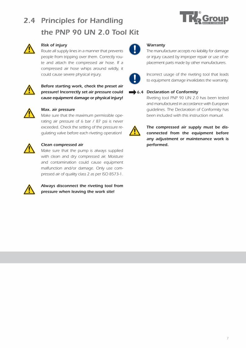
2.4 Principles for Handling
the PNP 90 UN 2.0 Tool Kit
Risk of injury Route all supply lines in a manner that prevents
people from tripping over them. Correctly rou-
te and attach the compressed air hose. If a
compressed air hose whips around wildly, it
could cause severe physical injury.
Before starting work, check the preset air pressure! Incorrectly set air pressure could cause equipment damage or physical injury!
Max. air pressure Make sure that the maximum permissible ope-
rating air pressure of 6 bar / 87 psi is never
exceeded. Check the setting of the pressure re-
gulating valve before each riveting operation!
Clean compressed air Make sure that the pump is always supplied
with clean and dry compressed air. Moisture
and contamination could cause equipment
malfunction and/or damage. Only use com-
pressed air of quality class 2 as per ISO 8573-1.
Always disconnect the riveting tool from pressure when leaving the work site!
Warranty The manufacturer accepts no liability for damage
or injury caused by improper repair or use of re-
placement parts made by other manufacturers.
Incorrect usage of the riveting tool that leads
to equipment damage invalidates the warranty.
Declaration of Conformity Riveting tool PNP 90 UN 2.0 has been tested
and manufactured in accordance with European
guidelines. The Declaration of Conformity has
been included with this instruction manual.
The compressed air supply must be dis-connected from the equipment before any adjustment or maintenance work is performed.
6.4
8
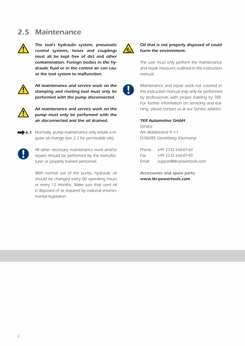
2.5 Maintenance
The tool‘s hydraulic system, pneumatic control sys tems, hoses and couplings must all be kept free of dirt and other contamination. Foreign bodies in the hy-draulic fluid or in the control air can cau-se the tool system to malfunction.
All maintenance and service work on the stamping and riveting tool must only be performed with the pump disconnected.
All maintenance and service work on the pump must only be performed with the air disconnected and the oil drained.
Normally, pump maintenance only entails a re-
gular oil change (see 2.2 for permissible oils).
All other necessary maintenance work and/or
repairs should be performed by the manufac-
turer or properly trained personnel.
With normal use of the pump, hydraulic oil
should be changed every 80 operating hours
or every 12 months. Make sure that used oil
is disposed of as required by national environ-
mental legislation.
6.1
Oil that is not properly disposed of could harm the environment.
The user must only perform the maintenance
and repair measures outlined in this instruction
manual.
Maintenance and repair work not covered in
this instruction manual may only be performed
by professionals with proper training by TKR.
For further information on servicing and trai-
ning, please contact us at our Service address:
TKR Automotive GmbH
Service
Am Waldesrand 9–11
D-58285 Gevelsberg (Germany)
Phone +49 2332 66607-60
Fax +49 2332 66607-90
Email [email protected]
Accessories and spare parts:www.tkr-powertools.com

9
Stamping and riveting tools from TKR Automotive GmbH come with a 12-month war-
ranty against material and manufacturing defects.
This does not cover wearing parts (rivet mandrels, rivet dies, spacing bolts and spacing
sleeves) or hydraulic oil.
The warranty period begins on the date of delivery, as specified on the invoice or de-
livery note.
The warranty is valid for the user/customer provided that the tool is obtained from an
authorised sales outlet and is used as described in the instructions and for the purposes
for which it was designed.
The warranty becomes invalid if the tool is used for purposes other than those for
which it was designed.
In addition, the warranty becomes invalid if the tool is not used as described in the
instruction manual.
In the event of defect or fault, TKR Automotive GmbH shall only repair or replace faulty
parts at its own discretion.
Your supplier and service partner: TKR Automotive GmbH
Service
Am Waldesrand 9–11
D-58285 Gevelsberg (Germany)
Phone +49 2332 66607-60
Fax +49 2332 66607-90
Email [email protected]
Accessories and spare parts:www.tkr-powertools.com
2.6 Warranty
104.7
246.5
50104.7
246.5
50
104.7
246.5
50
3.2.1 3.2.2
3.2.3
330
213
230
330
213
230
330
213
230
3.1.1
3.1.3
3.1.2
10
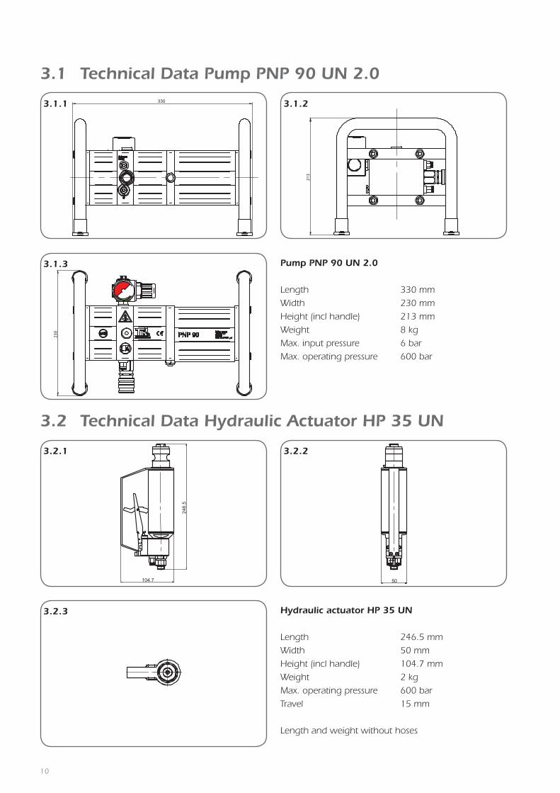
246.5 mm
50 mm
104.7 mm
2 kg
600 bar
15 mm
Length
Width
Height (incl handle)
Weight
Max. operating pressure
Travel
Hydraulic actuator HP 35 UN
3.2 Technical Data Hydraulic Actuator HP 35 UN
3.1 Technical Data Pump PNP 90 UN 2.0
330 mm
230 mm
213 mm
8 kg
6 bar
600 bar
Length
Width
Height (incl handle)
Weight
Max. input pressure
Max. operating pressure
Pump PNP 90 UN 2.0
Length and weight without hoses

3.3.1
AC
E
G
I
L
K
H
F
D
B
M
N
11
3.3 Technical Data Riveting Tool Kit RIVKIT UN 2.0
Riveting Tool Kit RIVKIT UN 2.0
WZS-TKR-00000024
Kit number Item/Description/Article number Item/Description/Article number
Kit: BGR-TKR- A Setting head, 3 mm rivet B Closing head, 3 mm rivet
00000024 BGR-TKR-00000244 01-00000707
Kit: BGR-TKR- C Setting head, 5 mm rivet D Closing head, 5 mm rivet
00000023 BGR-TKR-00000245 01-00000706
Kit: BGR-TKR- E Setting head, flow form rivet F Closing head, flow form rivet
00000048 Marked with 3 rings Marked with 3 rings
01-00000917 01-00000918
Kit: BGR-TKR- G Punch and calibration mandrel H Punch and calibration die
00000098 Marked with 2 rings Marked with 2 rings
01-00000922 01-00000923
Kit: BGR-TKR- I Extraction mandrel K Extraction die
00000128 Marked with 1 ring Marked with 1 ring
01-00000788 01-00000784
L Replacement elastomer rings M Set of fitting spanners
06-00000112 BGR-TKR-00000239
Kit: BGR-TKR N Spacing adaptor composed of:
00000025 1 Bushing, 01-00000744
2 Spacing bolt 01-00000704
3 Spacing sleeve 01-00000705
106
158.
8
80
45
25106
158.
8
80
45
25
10615
8.8
80
45
25
3.4.1
3.4.3
3.4.2
213
220.
3
44
8014
0.2
25
213
220.
3
44
8014
0.2
25
213
220.
3
44
8014
0.2
25
3.4.4
3.4.6
3.4.5
12
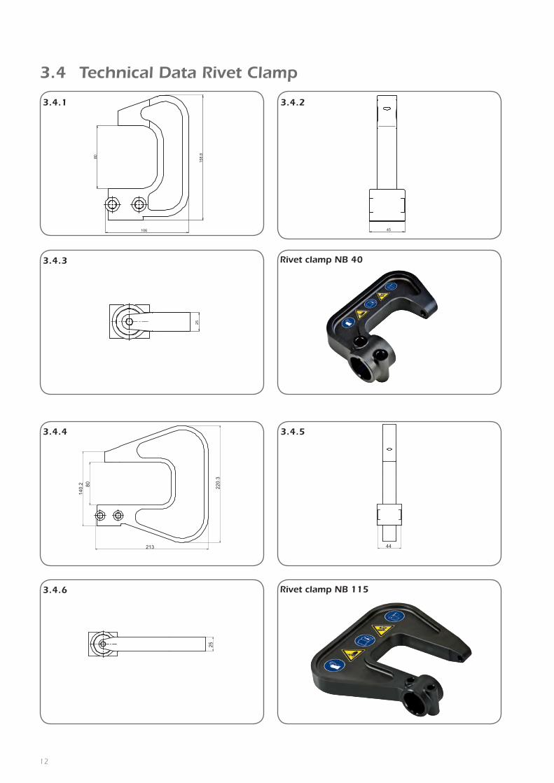
Rivet clamp NB 40
3.4 Technical Data Rivet Clamp
Rivet clamp NB 115

140
364.1
347.
2
44.5
30
140
364.1
347.
2
44.5
30
140
364.1
347.
2
44.5
30
3.4.7
3.4.9
3.4.8
13
Article number 05-00000026 WZS-TKR-00000027 WZS-TKR-00000026
Length* 106 mm 213 mm 364.1 mm
Width 45 mm 44 mm 44.5 mm
Height 158.8 mm 220.3 mm 347.9 mm
Clamp opening 80 mm 80 mm 140 mm
Opening depth 40 mm 115 mm 230 mm
Weight* 1.5 kg 3 kg 9.5 kg
Rivet clamp NB 230
Rivet clamp NB 401 Rivet clamp NB 115 Rivet clamp NB 230
*Length and weight without hoses 1Included in the basic kit
Technical data

4.1.1
4.1.44.1.3
14
G1/4“
The equipment is supplied from the factory without a
compressed air connection. The pressure regulator has a
G1/4“ (internal thread) connection thread.
4.1.1/4.1.2The pressure regulator is supplied with a closing cap fit-
ted. Remove the closing cap.
4.1.3/4.1.4Use a compressed air connection with R1/4“ thread and
seal. Screw this into the regulator.
4.1 Startup
4.1.2
R1/4“
4.2.1 4.2.2
4.2.3 4.2.4
15
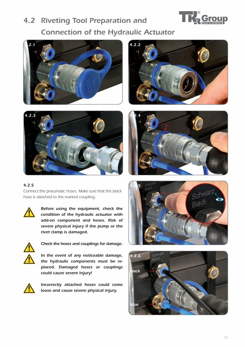
4.2 Riveting Tool Preparation and
Connection of the Hydraulic Actuator
Before using the equipment, check the condition of the hydraulic actuator with add-on component and hoses. Risk of severe physical injury if the pump or the rivet clamp is damaged.
Check the hoses and couplings for damage.
In the event of any noticeable damage, the hydraulic components must be re-placed. Damaged hoses or couplings could cause severe injury!
Incorrectly attached hoses could come loose and cause severe physical injury.
4.2.5
4.2.6
4.2.5 Connect the pneumatic hoses. Make sure that the black
hose is attached to the marked coupling.
black
blue

4.2.84.2.7
16
4.2 Riveting Tool Preparation and
Connection of the Hydraulic Actuator
4.2.8 Never use pressure over the permitted va-lue of 6 bar or 87 psi. This could cause damage to the equipment or even physical injury.
4.2.7 Connect compressed air to the pressure regulating valve
and set the pressure.
max. 6 bar / 87 psi

7
3
4.3.1
4.3.2
4.3.3
17
4.3 Safe Set-Up and Positioning of Equipment
Ensure that the high-pressure pump is always placed on a non-slip surface and that the hoses are routed in a way that prevents them from getting damaged or pinched off. The hoses must also be routed in a way that prevents people from tripping over them.
Make sure that the pump and hydraulic actuator are set up in a work area that is free from heat sources (max. 50°C / 120°F), corrosive liquids, greases and oils.
Before using the equipment, make sure that the pump is standing on a secure surface.

4.4.1 4.4.2
4.4.3
4.4.5
4.4.4
18
4.4 Connecting the Tool to the Hydraulic Actuator
Warning!The mounting adaptor on the hydraulic actuator must be clean and free from damage!The locking bolts must also be free from contamination and damage.The mounting hole in each tool must be free from contamination and damage!
Warning!Damaged or defective locking pins must not be used!
4.4.1/4.4.2Select tool and prepare locking pins. The tool is carefully
pushed onto the mounting adapter by the mounting
hole. The indexing pin in the mounting adaptor must
engage in the corresponding slots in the mounting hole.
4.4.3./4.4.4/4.4.5The two locking pins are inserted into the locking holes
with the release button pressed.
The tool must be pressed gently in the direction of the
clamp while doing so. The pin must lock automatically
once inserted and must not fall out of the locking hole
by itself.
The tool is now ready for use.

4.5.1 4.5.2
4.5.3
4.5.4
19
4.5 Riveting Tool Kit RIVKIT UN 2.0 –
Fitting and Intended Use
Three rivet clamps are currently available for use with the RIVKIT UN 2.0 riveting tool kit:
Rivet clamp Art. No. Opening depth
NB 401 05-00000026 up to 40 mm
NB 115 WZS-TKR-00000027 up to 115 mm
NB 230 WZS-TKR-00000026 230 mm
1Included in the basic kit
4.5.1/4.5.2Screw the riveting tool needed for the working process
into a holder in the rivet clamp as required. Hand-tighten
the riveting head using the special spanners provided. Do
not use force. Counterhold the nut using a screwdriver
if necessary.
4.5.3/4.5.4Screw the corresponding counterpart to the rivet insert
into the opposite side of the rivet clamp (plunger rod)
with the spacing bushing and bolt, and hand-tighten.
Do not use force!
Each time rivet inserts are to be fitted, the bolt and die must be checked for a correct match first!Refer to the usage matrix in the RIVKIT UN 2.0 case for details.
Check that the riveting heads are firmly seated after each riveting operation. Rivet inserts that have come loose present a hazard and can lead to destruction of the equipment.
5.1.2 01-00000788
5.1.4 5.1.5
5.1.6
5.1.1
75.1.3 01-00000784
20
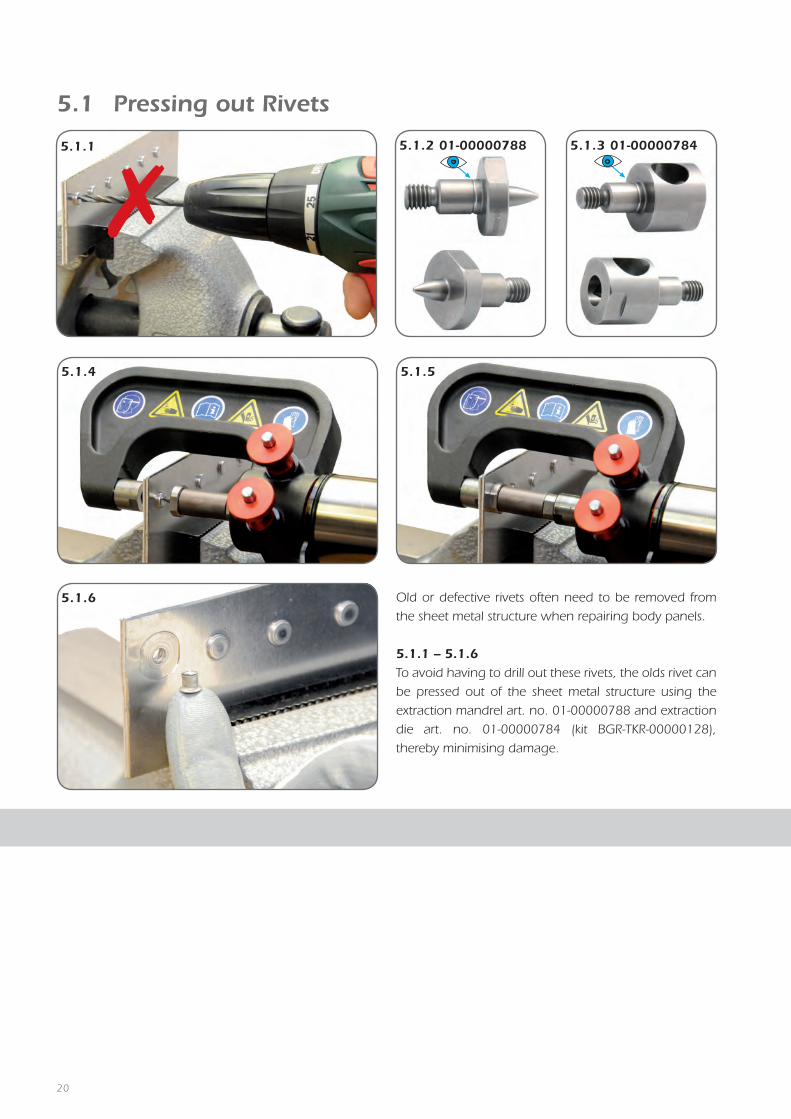
5.1 Pressing out Rivets
Old or defective rivets often need to be removed from
the sheet metal structure when repairing body panels.
5.1.1 – 5.1.6To avoid having to drill out these rivets, the olds rivet can
be pressed out of the sheet metal structure using the
extraction mandrel art. no. 01-00000788 and extraction
die art. no. 01-00000784 (kit BGR-TKR-00000128),
thereby minimising damage.
5.2.1 01-00000922 5.2.2 01-00000923 5.2.3
5.2.4
5.2.5
21
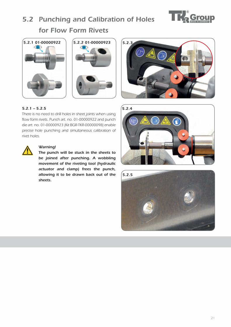
5.2 Punching and Calibration of Holes
for Flow Form Rivets
Warning!The punch will be stuck in the sheets to be joined after punching. A wobbling movement of the riveting tool (hydraulic actuator and clamp) frees the punch, allowing it to be drawn back out of the sheets.
5.2.1 – 5.2.5There is no need to drill holes in sheet joints when using
flow form rivets. Punch art. no. 01-00000922 and punch
die art. no. 01-00000923 (Kit BGR-TKR-00000098) enable
precise hole punching and simultaneous calibration of
rivet holes.
5.3.3
5.3.4 5.3.5
5.3.6
5.3.1 01-00000917 5.3.2 01-00000918
7,5 mm
22
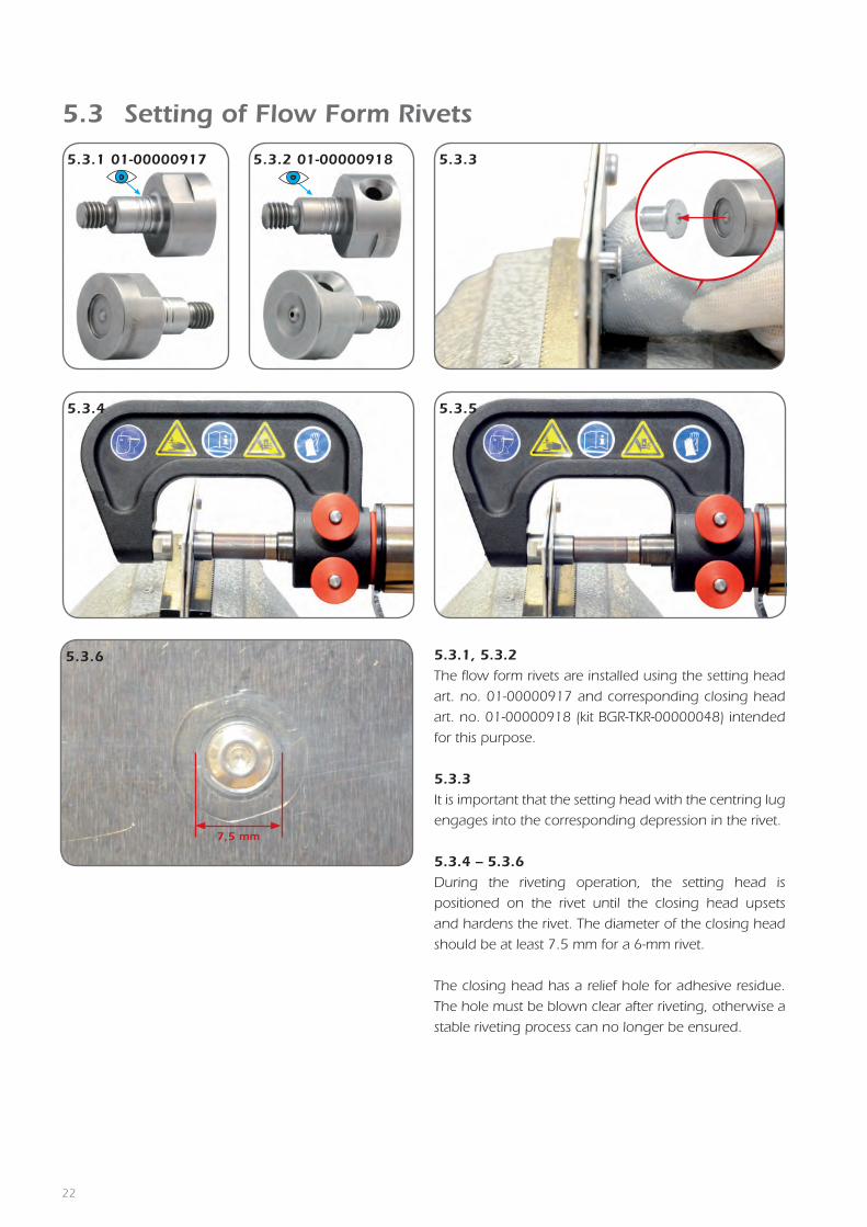
5.3 Setting of Flow Form Rivets
5.3.1, 5.3.2The flow form rivets are installed using the setting head
art. no. 01-00000917 and corresponding closing head
art. no. 01-00000918 (kit BGR-TKR-00000048) intended
for this purpose.
5.3.3It is important that the setting head with the centring lug
engages into the corresponding depression in the rivet.
5.3.4 – 5.3.6During the riveting operation, the setting head is
positioned on the rivet until the closing head upsets
and hardens the rivet. The diameter of the closing head
should be at least 7.5 mm for a 6-mm rivet.
The closing head has a relief hole for adhesive residue.
The hole must be blown clear after riveting, otherwise a
stable riveting process can no longer be ensured.
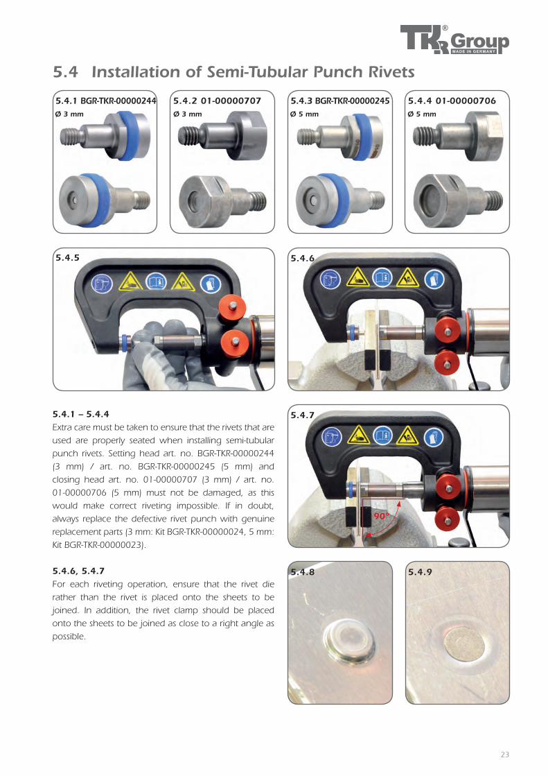
5.4.1 BGR-TKR-00000244 5.4.2 01-00000707 5.4.3 BGR-TKR-00000245 5.4.4 01-00000706Ø 3 mm Ø 3 mm Ø 5 mm Ø 5 mm
5.4.5 5.4.6
5.4.7
5.4.8 5.4.9
90°
23
5.4 Installation of Semi-Tubular Punch Rivets
5.4.1 – 5.4.4Extra care must be taken to ensure that the rivets that are
used are properly seated when installing semi-tubular
punch rivets. Setting head art. no. BGR-TKR-00000244
(3 mm) / art. no. BGR-TKR-00000245 (5 mm) and
closing head art. no. 01-00000707 (3 mm) / art. no.
01-00000706 (5 mm) must not be damaged, as this
would make correct riveting impossible. If in doubt,
always replace the defective rivet punch with genuine
replacement parts (3 mm: Kit BGR-TKR-00000024, 5 mm:
Kit BGR-TKR-00000023).
5.4.6, 5.4.7For each riveting operation, ensure that the rivet die
rather than the rivet is placed onto the sheets to be
joined. In addition, the rivet clamp should be placed
onto the sheets to be joined as close to a right angle as
possible.

5.6.1
5.6.2
24
5.5 Checking Riveting Results
5.5.1 5.5.2
5.5.3
5.5.1 – 5.5.3 The results must be checked after the riveting operation.
If the installed rivet does not meet quality requirements,
the reason for the fault must be determined.
If the quality of the installed rivet is acceptable, the work
process can be repeated.
After each riveting operation, check that the rivet mandrel and rivet die are firm-ly seated. Should they have come loose, they must be re-tightened using the span-ners from the RIVKIT.
5.6.1Remove adhesive residue from all contaminated tools after
each completed riveting operation.
5.6.2 To do this, remove all affected tool components and clean
using acetone or other solvents.
If adhesive residue is allowed to remain on the riveting tool, it will eventually cau-se a malfunction. Before starting work, any rivet punches requiring replacement must be replaced with genuine replace-ment parts.
5.6 Cleaning the Riveting Tools

5.7.1
5.7.2
5.7.3
5.7.55.7.4
25
5.7 Completing an Operation and Riveting Tool Storage
5.7.1Always disconnect the compressed air supply
from the pump after riveting and during work
interruptions.
5.7.2Then disconnect the control hoses and seal the
openings.
Make sure that the disconnected hoses never
make contact with the dirty floor or the ground.
5.7.3 Before and after each operation, check the sys-
tem for oil leaks. An oil leak indicates a fault in
the system. In this case, discontinue work and
locate the fault, or hand the equipment in for
repair at an autho rised specialist dealer.
Foreign bodies or contamination in the hydraulic oil or in the control lines could cause the equipment to malfunction.
5.7.4/5.7.5Always store the tool in the transport case designed for this purpose. Make sure that the hoses do not become kinked!
Never transport the tool by the hoses!

6.1.1
6.1.2 6.1.3
6.1.4
26
6.1 Hydraulic pump maintenance

6.1.5 6.1.6
6.1.7
6.1.8
27
Note that the oil must be free from con-tamination. Make sure that no dirt or foreign bodies enter the pump reservoir when changing oil!
280 ccm/9,86 fl oz
6.1.2 – 6.1.4 Draining oilUndo the sealing plug on the top of the pump and let
the used hydraulic fluid flow into a suitable container.
6.1.5, 6.1.6 Filling oilFill with fresh oil that complies with the specifications.
The nominal filling volume is around 280 ccm/9,86 fl oz.
6.1.7, 6.1.8 The oil level should reach the filler port when filling, but
the thread of the sealing plug must remain visible. Re-seal
the filler port with the sealing plug.
8
10
12
14
16
18
9
11
13
15
17
19
20
23
3
4
5
6
1 2
7
21
22
28
29
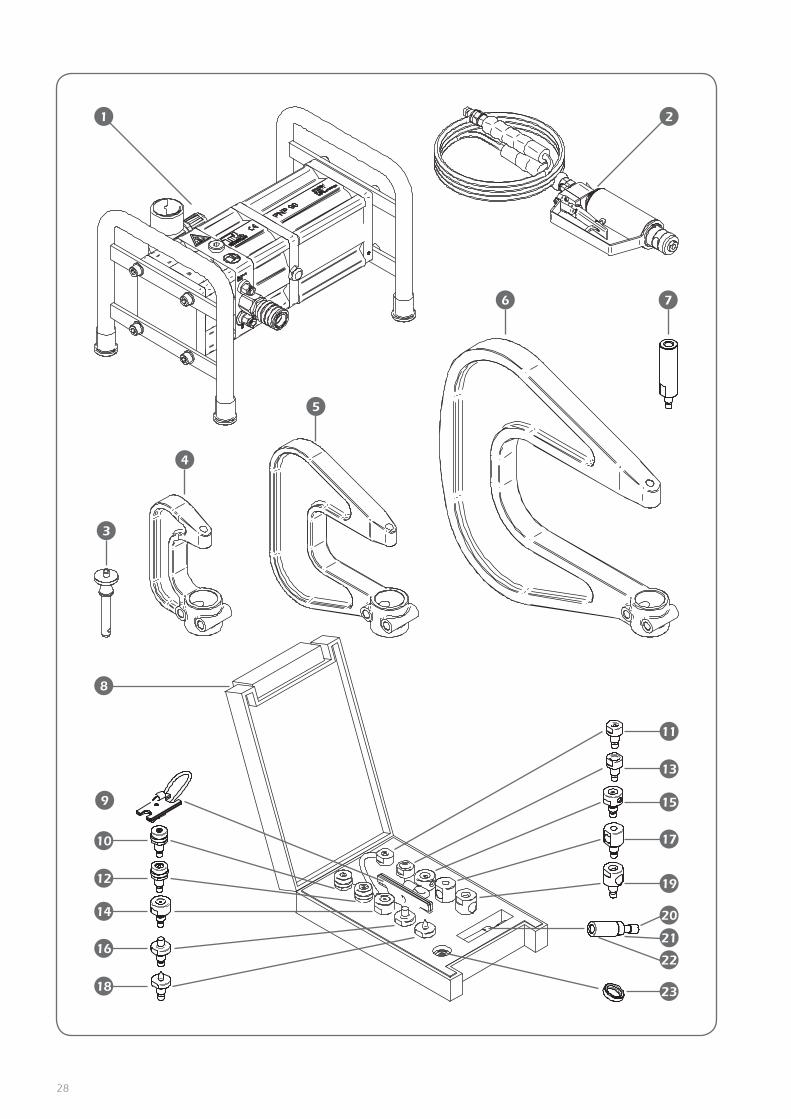
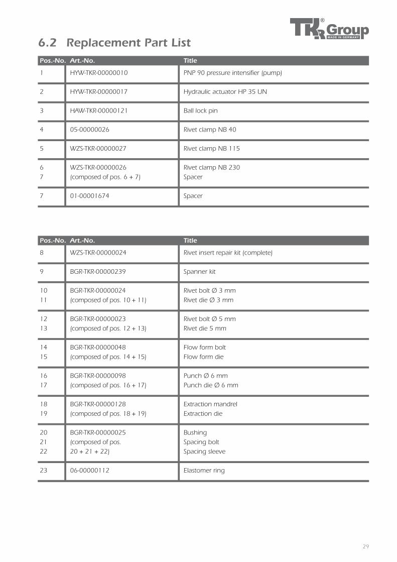
6.2 Replacement Part List
Pos.-No. Art.-No. Title
8 WZS-TKR-00000024 Rivet insert repair kit (complete)
9 BGR-TKR-00000239 Spanner kit
10 BGR-TKR-00000024 Rivet bolt Ø 3 mm
11 (composed of pos. 10 + 11) Rivet die Ø 3 mm
12 BGR-TKR-00000023 Rivet bolt Ø 5 mm
13 (composed of pos. 12 + 13) Rivet die 5 mm
14 BGR-TKR-00000048 Flow form bolt
15 (composed of pos. 14 + 15) Flow form die
16 BGR-TKR-00000098 Punch Ø 6 mm
17 (composed of pos. 16 + 17) Punch die Ø 6 mm
18 BGR-TKR-00000128 Extraction mandrel
19 (composed of pos. 18 + 19) Extraction die
20 BGR-TKR-00000025 Bushing
21 (composed of pos. Spacing bolt
22 20 + 21 + 22) Spacing sleeve
23 06-00000112 Elastomer ring
Pos.-No. Art.-No. Title
1 HYW-TKR-00000010 PNP 90 pressure intensifier (pump)
2 HYW-TKR-00000017 Hydraulic actuator HP 35 UN
3 HAW-TKR-00000121 Ball lock pin
4 05-00000026 Rivet clamp NB 40
5 WZS-TKR-00000027 Rivet clamp NB 115
6 WZS-TKR-00000026 Rivet clamp NB 230
7 (composed of pos. 6 + 7) Spacer
7 01-00001674 Spacer

30
6.3 TroubleshootingProblem Cause Remedy Page
Pump does not
run
No air connected Connect compressed air 16
Control lines not connected or incor-
rectly connected
Connect control lines correctly and make sure
they are properly seated15
Insufficient air pressure Check air supply 16
Hydraulic hose not connectedConnect hydraulic hose as described in the
instruction manual15
Air pressure not correctly set Set air pressure to prescribed value 16
Defective drive piston Repair through manufacturer –
Hydraulic pump
will not shut off
Control hoses incorrectly connected
or mixed up
Connect control hoses as described in the in-
struction manual15
Defective control valves Repair through manufacturer –
Rivet not affixed
correctly
Rivet mandrel or rivet die defective Replace rivet mandrel or rivet die 20
Rivet mandrel or rivet die not
functional due to adhesive residueClean or replace rivet mandrel and/or rivet die 24
Insufficient press pressureToo little air pressure or air pressure incorrectly
set16
Press cylinder does not travel far
enough
Too little oil in the pump. Check oil level and top
up if necessary.26
Oil leak from the pump Repair through manufacturer –
Air leak from the pump and/or control
valveRepair through manufacturer –
Wrong rivet length Observe repair guidelines –
The rivet plunger
travels too slowly
or not at all
Too little oil in the pump Check oil level and top up if necessary 26
Hydraulic seal in the pump is worn Repair through manufacturer –
Defect valves in the pump Repair through manufacturer –
Air leak
Defective hose Replace hose –
Defective couplings Replace coupling –
Defective seals Repair through manufacturer –
Oil leak
Defective hose Replace hose –
Defective coupling Replace coupling –
Pump loses oil Repair through manufacturer –

31
EU Declaration of ConformityIn accordance with EU Machinery Directive
2006/42/EG
Manufacturer: TKR Automotive Am Waldesrand 9-11 58285 Gevelsberg, Germany
Equipment type:
Tool type: Pneumatic/hydraulic stamping and riveting tool Type designation: PNP 90 UN 2.0
Developed and manufactured in accordance with the standards and guidelines listed below by TKR Automotive GmbH Am Waldesrand 9-11 58285 Gevelsberg (Germany)
Applied Tool Safety Law (GPSG) harmonised EN 693; EN 792-1; EN 792-13 Standards: EN ISO 4413; EN ISO 4414; ISO 11200; ISO 11202; EN ISO 12100
EU Machine Directive: 2006/42/EG As manufacturer, we declare that The products marked accordingly comply with the requirements of the referenced guidelines and standards. Gevelsberg, July 22, 2011 Torsten Kreischer CEO

PSD
-BED
-000
0001
5, V
ers.
12.
3
Am Waldesrand 9–11
D-58285 Gevelsberg (Germany)
Phone +49 2332 66607-77
Fax +49 2332 66607-51
Email [email protected]
Internet www.tkrgroup.com
Accessories and spare parts:www.tkr-powertools.com