universal field controller - rft tech notes/x1 - ixi-r1/en/bro... · 4 technical data safety...
TRANSCRIPT

www.rft.beRf-Technologies nv - Lange Ambachtstraat 40 - 9860 Oosterzele - Belgium - Tel +32 9 362 31 71 - Fax +32 9 362 33 07 - www.rft.be - [email protected]
UNIVERSAL FIELD CONTROLLER
Technical data
İxİ-R1
X1-B
01/2
018

2 CONTENT
Page
Technical Data 3
Cable specification 6
Dimensions 7
Removing the Cover 8
Electrical Installation 9
Addressing 10
Configuration through DIP Switch 11
Connection Details 12
Analog Application 15
LEDs 16
Applications 17
System Layout 19

3TECHNICAL DATA
Universal field controller for motorized fire and smoke extraction dampers, for bus (Modbus or BACnet) or analog integration into a superior system
Electrical Data Nominal Voltage 24 V AC / DC Nominal Voltage Range -20%... + 20% Dimensioning 2 VA + damper actuator (max. 24 VA) Power Consumption 2 W + damper actuator Connections AMP plug-in connections and quick connections (terminals)
Communication / Modbus Protocol Modbus RTU Medium RS-485, not electrically isolated Transmission Formats Specified by Modbus RTU Standards Number of Devices per Line 100 (without repeater) Baud Rates 9’600, 19’200, 38’400, 76’800 bps Address 1..127 (1-10 reserved for İxİ-R200+) (0 reserved for broadcast) Termination 120 ohm line termination. Jumper available on extra pin on PCB. Position of jumper if İxİ-R1 is last Modbus device in line see electrical installation, page 9 Typical Response Time <200 ms
Communication / BACnet Protocol BACnet MS/TP Medium RS-485, not electrically isolated Number of Devices per Line 65 (without repeater) Baud Rates 9’600, 19’200, 38’400, 76’800 bps (auto detect) Termination 120 ohm line termination. Jumper available on extra pin on PCB. Position of jumper if İxİ-R1 is last BACnet device in line see electrical installation, page 9 Typical Response Time <100 ms Device Instant Automatically assigned by physical address, writable
4 TECHNICAL DATA
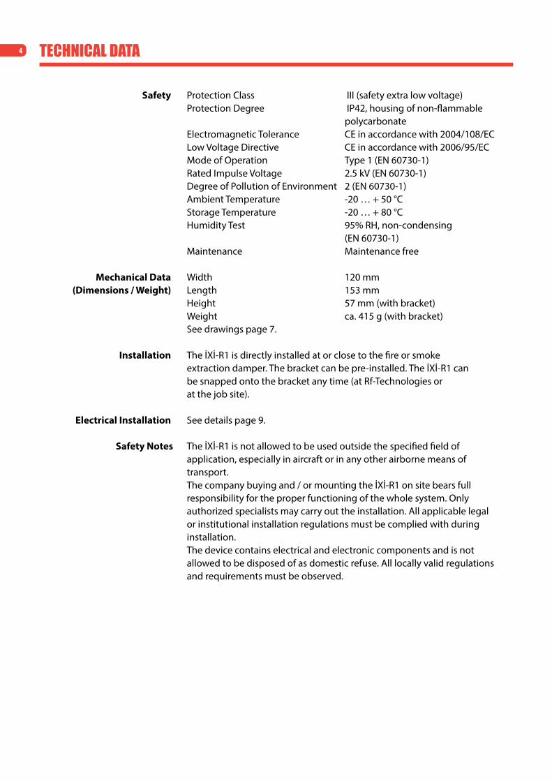
Safety Protection Class III (safety extra low voltage) Protection Degree IP42, housing of non-flammable polycarbonate Electromagnetic Tolerance CE in accordance with 2004/108/EC Low Voltage Directive CE in accordance with 2006/95/EC Mode of Operation Type 1 (EN 60730-1) Rated Impulse Voltage 2.5 kV (EN 60730-1) Degree of Pollution of Environment 2 (EN 60730-1) Ambient Temperature -20 … + 50 °C Storage Temperature -20 … + 80 °C Humidity Test 95% RH, non-condensing (EN 60730-1) Maintenance Maintenance free
Mechanical Data Width 120 mm (Dimensions / Weight) Length 153 mm Height 57 mm (with bracket) Weight ca. 415 g (with bracket) See drawings page 7.
Installation The İxİ-R1 is directly installed at or close to the fire or smoke extraction damper. The bracket can be pre-installed. The İxİ-R1 can be snapped onto the bracket any time (at Rf-Technologies or at the job site).
Electrical Installation See details page 9.
Safety Notes The İxİ-R1 is not allowed to be used outside the specified field of application, especially in aircraft or in any other airborne means of transport.
The company buying and / or mounting the İxİ-R1 on site bears full responsibility for the proper functioning of the whole system. Only authorized specialists may carry out the installation. All applicable legal or institutional installation regulations must be complied with during installation.
The device contains electrical and electronic components and is not allowed to be disposed of as domestic refuse. All locally valid regulations and requirements must be observed.

5TECHNICAL DATA
Product Features / Application The İxİ-R1 is used together with a fire or smoke extraction damper actuator to control and monitor one fire or smoke extraction damper. It offers Modbus, BACnet or analog connection and is normally mounted at or close to the damper. Following control modes can be chosen through DIP switch terminal:
• Fireorsmokeextractionapplication • Busprotocols:ModbusorBACnet • Analog:Inputandoutputsignals
The digital input in the IxI-R1 always overrides the bus commands.Universal System Link between fire or smoke extraction damper and any
Modbus or BACnet system or analog control.
Power Supply The İxİ-R1 needs to be powered up with 24 V AC / DC. The İxİ-R1 provides the power supply to the actuator and to other connected devices (e. g. smoke detector).
Control Conventional (analog) The İxİ-R1 has the option to work without the bus communication
connected. The input allows to open or close the damper, depending on the
application (fire or smoke extraction). It is also possible to monitor the damper position conventionally through a digital output signal. There is one analog output to signalize the status of the İxİ-R1 and the actuator.
This analog output can be read from any controller.
Serial Communication – RS-485 Through Modbus RTU (RS-485) or BACnet MS/TP (RS-485).
Actuator Connection 3-pole AMP plug and terminal connection for standard 24 V AC/DC fire or smoke extraction actuator.
6-pole AMP plug and terminal connection for 2 internal actuator end switches. Identification of the end position switches of the actuators.
Additional Connections Input Modules 2-pole AMP plug and 3-pole connection (terminal) for thermoelectric tripping device. Dry contact input.
4-pole connection (terminal) for smoke detector (incl. power supply). Dry contact input. Digital input for analog application.
Output Module 1 analog output, indicates the status of the İxİ-R1.

6 CABle speCifiCAtion
Cable Specification 120Ω at 1 Mhz. Made of 24# flexible twisted pairs overall foil + braidshielded and overall jacketed with a flexible compound for indoor use, or similar. (Cable type: Belden 3105a or equivalent)
A B A B A B A BİXİ-R1 İXİ-R1 İXİ-R1 İXİ-R1
120Ω at 1 Mhz, made of 24# exible twisted pairs overall foil + braid shielded and overall jacketed with a exible compound for indoor use
Wires are interconnected beteween them and then inserted to the terminal
The shield is connected in between the wires but not connected to the controller İXİ-R1
The shield is connected to tested ground at one point in all trunk (no matter middle or end)
Up to 1200 meters and max. 100 IXI-R1 with Modbus RTU and 65 IXI-R1 with BACnet MS/TP

7diMensions
İXİ-R1
Mounting Bracket
120
57 mm
153
incl. bracket
116
70
153 100 130
Ø4,5
8 rEmOvINg THE COvEr
1. Open the lid 2. Unlock the screw
3. Move the sliding cover10 mm to the top
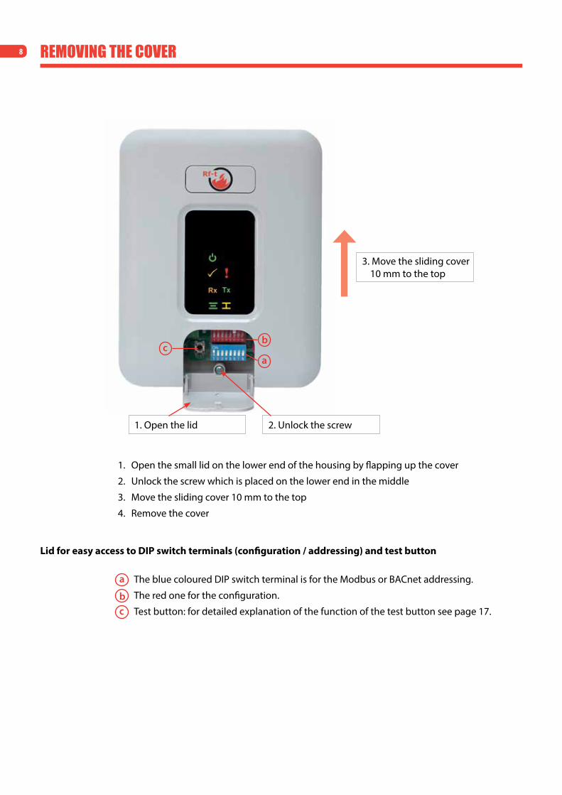
1. Open the small lid on the lower end of the housing by flapping up the cover
2. Unlock the screw which is placed on the lower end in the middle
3. Move the sliding cover 10 mm to the top
4. Remove the cover
Lid for easy access to DIP switch terminals (configuration / addressing) and test button
The blue coloured DIP switch terminal is for the Modbus or BACnet addressing.
The red one for the configuration.
Test button: for detailed explanation of the function of the test button see page 17.
a
a
b
b
c
c

9
ABC R1 C
ON
1 2 3 4 5 6 87
4153
26
R1 C
+24-24
DI2
CD
I3C
C
S1S2
S3 S4S5
S6
ON
1 2 3 4 5 6 87
1 C 2
DI1
CA
O1
C
120Ω
Analog OutputSignals the status of the İXİ-R1
Configuration İXİ-R1
Modbus/BACnet addressing
End Switchesfrom Actuator
AMP Plug in parallel
Conventional ApplicationDigital input for manual overrideCan be selected via bus as “Normally Open” (=standard open) or“Normally Closed” (=standard closed)Default = “Normally Open”
Position of line termination120 ohm if İXİ-R1 is last Modbus or BACnet device in line
Smoke Detector24VDC – Power supply – max 25mADigital input – 24VCan be selected via bus as “Normally Open” or “Normally Closed”Default = “Normally Closed” – factoryproduction short
Thermoelectric Tripping DeviceDigital input – dry contactFactory production – shortWhen contact open – damper closes
RS-485 ComsModbus RTU or BACnet MS/TP
dip switch selectable
Main 24V AC/DCDaisy Chain
from and to other İXİ-R1
Power to Actuator Fire Application:
1-Open C-CommonSmoke Extr. Application:
1-Close C-Common 2-Open
ThermoelectricTripping Dev.
Coms Power In Power Out / Damper
DAMPER OUT
Power
Close
Status
TXRX
Open
Error
TestButton
ADDRESS
CONF
R1 Com Com Com Com Com Com Com Com
24VAC/DC
24VAC/DC
24VAC/DC 24VAC/DC 24VAC/DC
R1 R1 R1R1 R1 R1 R1
Actuator Actuator Actuator Actuator
Power In Power Out Power In Power Out Power In Power Out Power In Power Out
eleCtriCAl instAllAtion
General Information
Power Supply:
Main Power – İXİ-R1
The İxİ-R1 is dual power 24V AC/DC.The actuator has to be 24V AC and/or DC. Meaning it has to operate with the same voltage (AC or DC) as the İxİ-R1. There are 2 terminals for the power, in order to make the daisy chain connection for the installer easier.
Caution: The polarity must be respected when connecting multiple IXI-R1 to one power source (phase to phase, com to com)

10 Addressing
Modbus and BACnet Addressing
*Attention: If the İxİ-R1 is used in combination with the İxİ-R200+ controller, Modbus addresses 1 – 10 are reserved for the İxİ-R200+. That means that the Modbus addressing of the İxİ-R1 starts with Modbus address 11. Furthermore the Baud rate must be changed to 38.400 (red DIP switch PIN 5 to ON).If the IxI-R1 is used in combination with the IxI-R120, the addressing needs to be done in consecutive order.
Address Switches On Address Switches On Address Switches On Address Switches On
0* Broadcast-not in use 33 1+6 66 2+7 99 1+2+6+7
1* 1 34 2+6 67 1+2+7 100 3+6+7
2* 2 35 1+2+6 68 3+7 101 1+3+6+7
3* 1+2 36 3+6 69 1+3+7 102 2+3+6+7
4* 3 37 1+3+6 70 2+3+7 103 1+2+3+6+7
5* 1+3 38 2+3+6 71 1+2+3+7 104 4+6+7
6* 2+3 39 1+2+3+6 72 4+7 105 1+4+6+7
7* 1+2+3 40 4+6 73 1+4+7 106 2+4+6+7
8* 4 41 1+4+6 74 2+4+7 107 1+2+4+6+7
9* 1+4 42 2+4+6 75 1+2+4+7 108 3+4+6+7
10* 2+4 43 1+2+4+6 76 3+4+7 109 1+3+4+6+7
11 1+2+4 44 3+4+6 77 1+3+4+7 110 2+3+4+6+7
12 3+4 45 1+3+4+6 78 2+3+4+7 111 1+2+3+4+6+7
13 1+3+4 46 2+3+4+6 79 1+2+3+4+7 112 5+6+7
14 2+3+4 47 1+2+3+4+6 80 5+7 113 1+5+6+7
15 1+2+3+4 48 5+6 81 1+5+7 114 2+5+6+7
16 5 49 1+5+6 82 2+5+7 115 1+2+5+6+7
17 1+5 50 2+5+6 83 1+2+5+7 116 3+5+6+7
18 2+5 51 1+2+5+6 84 3+5+7 117 1+3+5+6+7
19 1+2+5 52 3+5+6 85 1+3+5+7 118 2+3+5+6+7
20 3+5 53 1+3+5+6 86 2+3+5+7 119 1+2+3+5+6+7
21 1+3+5 54 2+3+5+6 87 1+2+3+5+7 120 4+5+6+7
22 2+3+5 55 1+2+3+5+6 88 4+5+7 121 1+4+5+6+7
23 1+2+3+5 56 4+5+6 89 1+4+5+7 122 2+4+5+6+7
24 4+5 57 1+4+5+6 90 2+4+5+7 123 1+2+4+5+6+7
25 1+4+5 58 2+4+5+6 91 1+2+4+5+7 124 3+4+5+6+7
26 2+4+5 59 1+2+4+5+6 92 3+4+5+7 125 1+3+4+5+6+7
27 1+2+4+5 60 3+4+5+6 93 1+3+4+5+7 126 2+3+4+5+6+7
28 3+4+5 61 1+3+4+5+6 94 2+3+4+5+7 127 Reserved factory defaults
29 1+3+4+5 62 2+3+4+5+6 95 1+2+3+4+5+7
30 2+3+4+5 63 1+2+3+4+5+6 96 6+7
31 1+2+3+4+5 64 7 97 1+6+7
32 6 65 1+7 98 2+6+7
ON
1 2 3 4 5 6 87
ADDRESS

11ConfigUrAtion throUgh dip switCh
Default DIP Switch Position
Configuration Possibilities
Information Pin 2:If the position of Pin 2 is changed, the IxI-R1 needs to be taken off the power supply and put back to activate the new mode.
Information Pin 3:If the IxI-R1 is used in connection with the IxI-R120, Pin 3 must be on ON (BACnet).
Information Pin 5:If the IxI-R1 is used in connection with the IxI-R200+, Pin 5 must be on ON (Baud rate 38.400)
Information Pin 7: • SmokeDetectorAlarm“System”:thesignalofthesmokedetectoristransferreddirectlytothesystem and processed there.
• SmokeDetectorAlarm“Actuator“:thesignalofthesmokedetectorisdirectlylinkedwiththe actuator. In case of a smoke detector alarm the fire damper connected to the same İxİ-R1 will be closed. The signal of the smoke detector is forwarded to the controller.
The above is only valid for the fire safety application. In the smoke extraction application the signal of the smoke detector has no direct influence to the actuator. The signal will be forwarded to the system in any case.
Baud Rate Selection (Modbus)This has to be done when choosing Modbus only. In BACnet Baud rate is automatically detected.
Pin Off (Default) On1 Bus Analog
2 Fire Application Smoke Extr. Application3 Modbus RTU BACnet MS/TP
4 Baud Rate (Off-Default)5 Baud Rate (Off-Default)6 Not In Use=Off7 SmokeDetectorAlarm“System“ SmokeDetectorAlarm“Actuator“
8 Not In Use=Off
9 600 (Default) 19 200 38 400 76 8004 Off On Off On
5 Off Off On On
CONFON
1 2 3 4 5 6 87
12
CONFON
1 2 3 4 5 6 87
CONFON
1 2 3 4 5 6 87
1 2Com
Power to Actuator
OpenClose
Smoke Damper ActuatorPower Open and
Power Close
1 2Com
Power to Actuator
Open Close
Fire DamperActuator
Spring Return
1 2Com
21 Com
3
21
21
Open Close
OpenClose
When the İXİ-R1 is powered, the power to the actuator is on
output 'open' (pin nr 1).
On power up the CLOSEoutput will be ON.
During normal operation the İXİ-R1, in this application ONLY, will hold the
last command on memory.
ConneCtion detAils
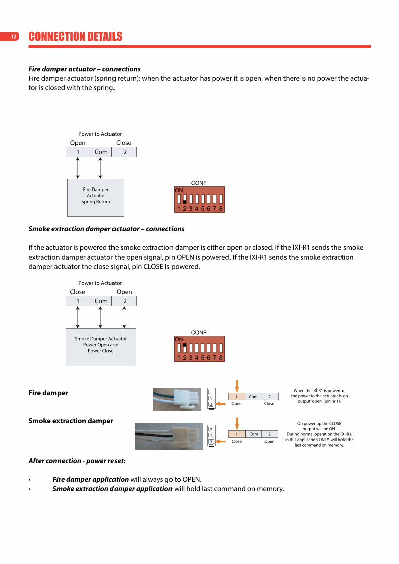
Fire damper actuator – connections Fire damper actuator (spring return): when the actuator has power it is open, when there is no power the actua-tor is closed with the spring.
Smoke extraction damper actuator – connections
If the actuator is powered the smoke extraction damper is either open or closed. If the İxİ-R1 sends the smoke extraction damper actuator the open signal, pin OPEN is powered. If the İxİ-R1 sends the smoke extraction damper actuator the close signal, pin CLOSE is powered.
Fire damper
Smoke extraction damper
After connection - power reset:
• Fire damper application will always go to OPEN.• Smoke extraction damper application will hold last command on memory.

13
DI3
CC
AMG plug in parallel
Digital input - dry contactFactory production - short
When contact open - damper close
ConneCtion detAils
Thermoelectric tripping device - connection
Digital input volt free, normally close as default (can be changed on bus). When this input is active the damper will close and you can override from the bus. The 2 connections, the normal quick terminals and the AMP connector are in parallel.AMP plug 2-pole. Quick connector 3-pole.
When a thermoelectric tripping device is mounted in the 2-pole AMP plug, the factory production mounted jumper between DI3 and C must be removed!
The above is only valid for the fire safety application.
Electrical installation thermoelectric tripping device

14 ConneCtion detAils
Communication interface
Smoke detector connection Hekatron ORS 142
Smoke detector connection Calectro EVC-PY-DA
Multiple smoke detector connections possible with ABAV-S3 24V central unit from Calectro
Smoke detectors – connections
Possibility to connect one smoke detector
Operating voltage Relay contact
The ORS 142 may only be connected to Hekatron mainspower devices and matches the existing bases type 143.
İXİ-R1
24V DC 1245
24V DCDI2
Com
56
43
2
1
-
+
İXİ-R1
24V DC XXXX
6365
6365
6365
24V DCDI2
Com
External PowerSupply
ABAV-S3 24VCalectro
central unit
EVC-PY-DACalectro smoke
detector
EVC-PY-DACalectro smoke
detector
EVC-PY-DACalectro smoke
detector

15AnAlog AppliCAtion
Electrical installation for conventional application:
Feedback signal from the IxI-R1:
İXİ-R1
AO.1 Com
AO.1 Com AO.1 Com AO.1 Com
İXİ-R1 İXİ-R1
Analog Output Layout - Example
Programmable controller
with analog input AnalogInput
AnalogInput
SmokeDetector
Thermoel. Tripping Device
Analog Connection
Analog Ouput - Signals the Status of İXİ-R1 0V - No Power to İXİ-R1 2V - Damper Open 4V - Damper Close 6V - Smoke Detector Alarm 8V - Thermoel. Tripping Device Alarm 10V - More than one Alarm Condition
S1 S2 S3 S4
S5
S6
Contact Open
Contact Close
The IxI-R1 can be used without bus communication. There is one input to open or close the damper, depending on the application (fire or smoke extraction). It is also possible to monitor the damper position conventionally through a digital output signal.
Digital input volt free, normally open as default (can be changed on bus).The digital input allows to control the damper position through an external contact/device. Selection by DIP switch.
This digital input for the analog application in the İXİ-R1 always overrides the bus commands.
The analog output, signals the status of the İxİ-R1:• 0V – No power to İxİ-R1• 2V – Damper open • 4V – Damper close• 6V – Smoke detector alarm • 8V – Thermoelectric tripping device alarm • 10V – More than one alarm condition
During normal operation this output will signalize the position of the damper (2V, 4V).This output can be connected in parallel between the various İxİ-R1 in order to monitor their status.Current output max is 5mA.
Electrical installation for analog application:
16 led's
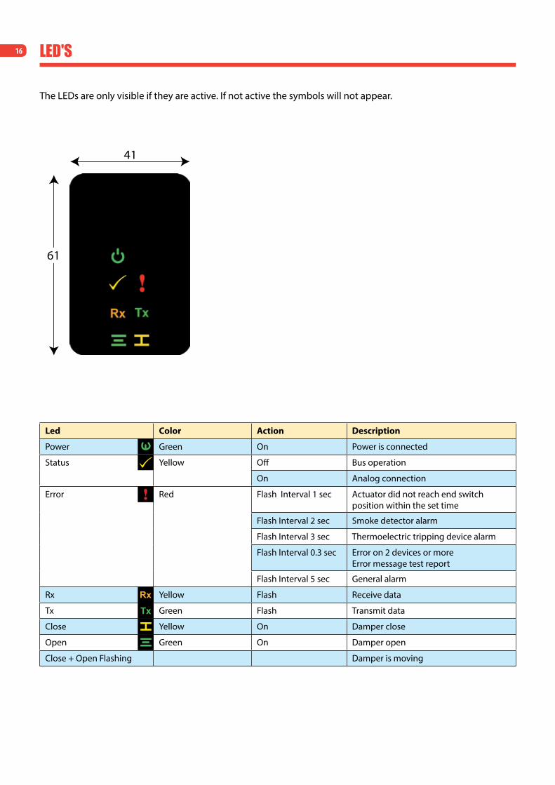
The LEDs are only visible if they are active. If not active the symbols will not appear.
Led Color Action Description
Power Green On Power is connected
Status Yellow Off Bus operation
On Analog connection
Error Red Flash Interval 1 sec Actuator did not reach end switch position within the set time
Flash Interval 2 sec Smoke detector alarm
Flash Interval 3 sec Thermoelectric tripping device alarm
Flash Interval 0.3 sec Error on 2 devices or more Error message test report
Flash Interval 5 sec General alarm
Rx Yellow Flash Receive data
Tx Green Flash Transmit data
Close Yellow On Damper close
Open Green On Damper open
Close + Open Flashing Damper is moving
41
61
17AppliCAtions
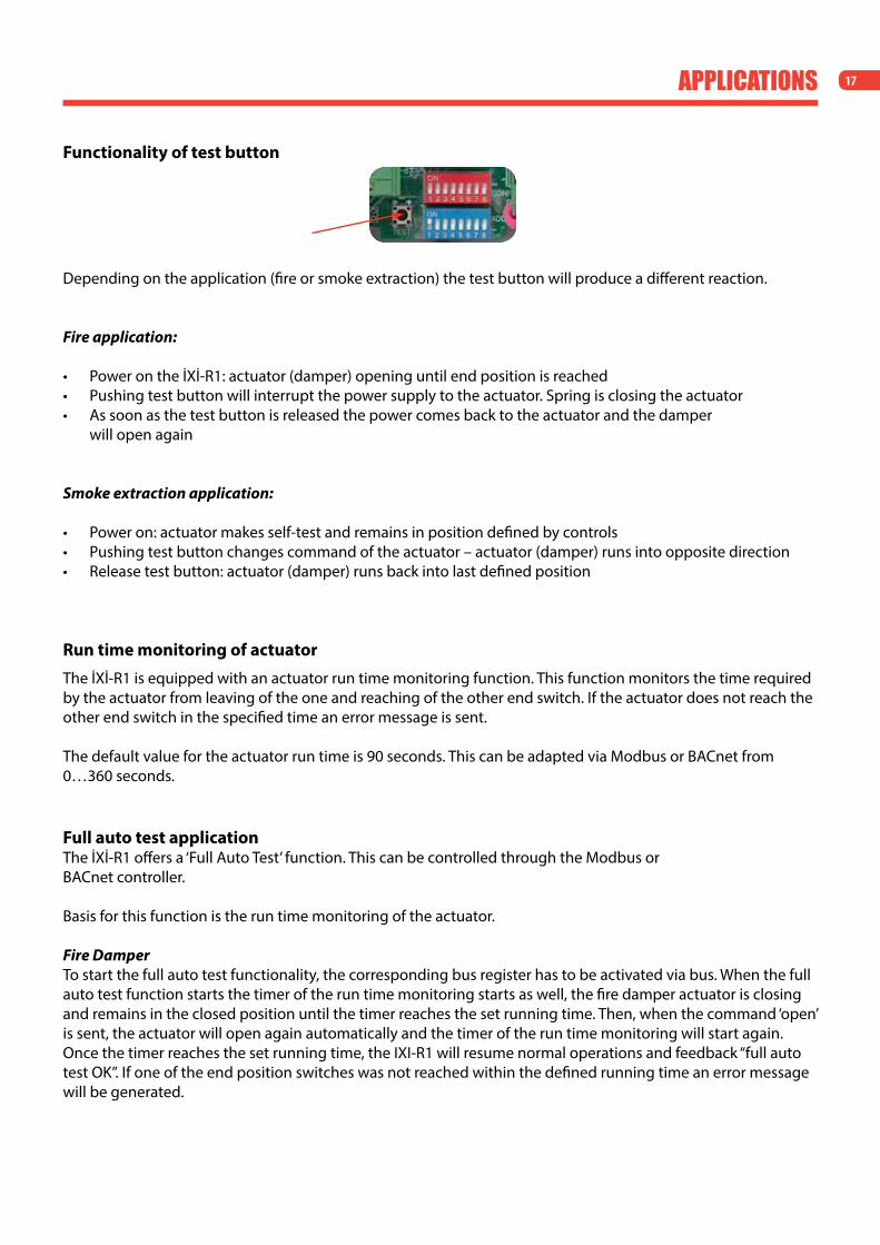
Functionality of test button
Depending on the application (fire or smoke extraction) the test button will produce a different reaction.
Fire application:
• Power on the İxİ-R1: actuator (damper) opening until end position is reached• Pushing test button will interrupt the power supply to the actuator. Spring is closing the actuator• As soon as the test button is released the power comes back to the actuator and the damper
will open again
Smoke extraction application:
• Power on: actuator makes self-test and remains in position defined by controls• Pushing test button changes command of the actuator – actuator (damper) runs into opposite direction• Release test button: actuator (damper) runs back into last defined position
Run time monitoring of actuator
The İxİ-R1 is equipped with an actuator run time monitoring function. This function monitors the time required by the actuator from leaving of the one and reaching of the other end switch. If the actuator does not reach the other end switch in the specified time an error message is sent.
The default value for the actuator run time is 90 seconds. This can be adapted via Modbus or BACnet from 0…360 seconds.
Full auto test applicationThe İxİ-R1 offers a ‘Full Auto Test’ function. This can be controlled through the Modbus or BACnet controller.
Basis for this function is the run time monitoring of the actuator.
Fire DamperTo start the full auto test functionality, the corresponding bus register has to be activated via bus. When the full auto test function starts the timer of the run time monitoring starts as well, the fire damper actuator is closing and remains in the closed position until the timer reaches the set running time. Then, when the command ‘open’ is sent, the actuator will open again automatically and the timer of the run time monitoring will start again. Oncethetimerreachesthesetrunningtime,theIXI-R1willresumenormaloperationsandfeedback“fullautotestOK”.Ifoneoftheendpositionswitcheswasnotreachedwithinthedefinedrunningtimeanerrormessagewill be generated.

18 AppliCAtions
Smoke Extraction DamperTo start the full auto test functionality, the corresponding bus register has to be activated via bus. When the full auto test function starts the timer of the run time monitoring starts as well, the smoke extraction damper actuator is changing position and remains in that position until the timer reaches the set running time. Then the actuator will move back to its original position and the timer of the run time monitoring will start again. Once thetimerreachesthesetrunningtime,theIXI-R1willresumenormaloperationsandfeedback“fullautotestOK”.Ifoneoftheendpositionswitcheswasnoreachedwithinthedefinedrunningtimeanerrormessagewillbe generated.
Bus monitoring applicationThe IxI-R1 is equipped with a bus monitoring function. If the bus signal to the unit is interrupted the damper will move to the safety position after a defined period of time and remain there until the bus communication is restored.Two objects can be activated by Modbus or BACnet:• Logic alarm communication (default: not active)• Delay alarm communicationActivation via bus (controller):• Logic alarm communication 1 (on)• Delay alarm communication is activated, default delay time is 120 sec. Option to set the delay time via bus
from 30 sec to 360 sec.
Fire damperWhen activated the fire damper will move to the closed position after the set time delay. It will remain closed until bus communication is restored.
Smoke extraction damperIf the damper is closed: when activated the damper will move to the open position after the set time delay. It will remain open until bus communication is restored.If the damper is open: the damper remains in open position.

19sYsteM lAYoUt
İXİ-R1 İXİ-R1
Mod
bus
BACn
et
İXİ-R200+
24 V AC/DC 24 V AC/DC
Cabinet Level
Field/Damper Level
Any Modbus or BACnet controller*
Controller/Building Management Level
*Upon request, Rf-Technologies supplies the functional prole of the İXİ-R1 for easy integration into any Modbus or BACnet controller.
Option
FIRE
ALARM
Motorized Fire Damper
Smoke Detector
Thermoelectric Tripping Device
Legend:
Cabinet Level
Field/Damper Level
Any Modbus or BACnet controller*
Controller/Building Management Level
*Upon request, Rf-Technologies supplies the functional prole of the İXİ-R1 for easy integration into any Modbus or BACnet controller.
Option
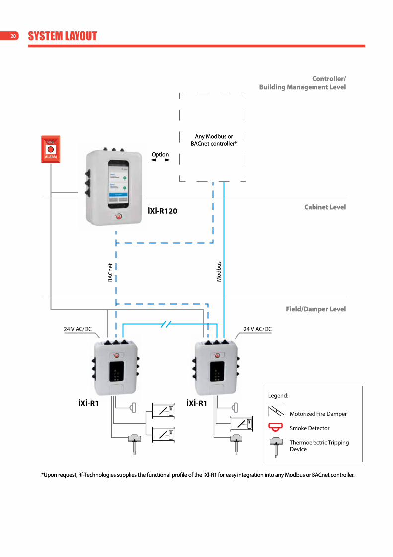
20 sYsteM lAYoUt
İXİ-R1 İXİ-R1
BACn
et
İXİ-R120
24 V AC/DC 24 V AC/DC
Mod
bus
Cabinet Level
Field/Damper Level
Any Modbus or BACnet controller*
Controller/Building Management Level
*Upon request, Rf-Technologies supplies the functional prole of the İXİ-R1 for easy integration into any Modbus or BACnet controller.
Option
FIRE
ALARM
Motorized Fire Damper
Smoke Detector
Thermoelectric Tripping Device
Legend:
Cabinet Level
Field/Damper Level
Any Modbus or BACnet controller*
Controller/Building Management Level
*Upon request, Rf-Technologies supplies the functional prole of the İXİ-R1 for easy integration into any Modbus or BACnet controller.
Option