united states patent patent no.: us 7,499,490 b2
TRANSCRIPT
240
outputodeword
mu uuuu ui iiui iiui mu mu uui uui mu uui iiuii uu uii mi
(12) United States Patent (1o) Patent No.: US 7,499,490 B2Divsalar et al. (45) Date of Patent: Mar. 3, 2009
(54) ENCODERS FOR BLOCK -CIRCULANT LDPC 6,014,411 A 1/2000 WangCODES 6,023,783 A 2/2000 Divsalar et al.
(75) Inventors: Dariush Divsalar, Pacific Palisades, CA6,473,010 BI 10/2002 Vityaev et al.
(US); Aliazam Abbasfar, Cupertino, CA 6,518,892 132 2/2003 Shen et al.
(US); Christopher R. Jones, Pacific 6,539,367 BI 3/2003 Blanksby et al.
Palisades, CA (US); Samuel J. Dolinar, 6,560,362 BI 5/2003 Piret et al.Sunland, CA (US); Jeremy C. Thorpe, 6,567,465 132 5/2003 Goldstein et al.Redlands, CA (US); Kenneth S. 6,633,856 132 10/2003 Richardson et al.Andrews, Pasadena, CA (US); KungYao, Sherman Oaks, CA (US) 6,686,853 B2 2/2004 Shen et al.
6,715,121 BI 3/2004 Laurent
(73) Assignees: California Institute of Technology, 6,718,502 BI 4/2004 Kuznetsov et al.Pasadena, CA (US); The Regents of the 6,724,327 BI 4/2004 Pope et al.University of California, Oakland, CA 6,757,122 BI 6/2004 Kuznetsov et al.(US) 6,769,091 132 7/2004 Classon et al.
(*) Notice: Subject to any disclaimer, the term of this 6,771,197 BI 8/2004 Yedidia et al.
patent is extended or adjusted under 35U.S.C. 154(b) by 729 days.
(21) Appl. No.: 11/166,041 (Continued)
(22) Filed: Jun. 24, 2005 OTHER PUBLICATIONS
(65) Prior Publication Data
US 2006/0291571 Al Dec. 28, 2006
(51) Int. Cl.
H04B 1166 (2006.01)(52) U.S. Cl . ....................... 375/240; 375/254; 375/271;
375/302; 341/51; 341/74; 714/758; 714/800(58) Field of Classification Search ....................... None
See application file for complete search history.
(56) References Cited
U.S. PATENT DOCUMENTS
3,542,756 A 11/1970 Gallager
3,655,396 A 4/1972 Gotoetal.
4,295,218 A 10/1981 Tanner
5,023,889 A 6/1991 Divsalar et al.
5,729,560 A 3/1998 Hagenauer et al.
5,734,962 A 3/1998 Hladik et al.
Yu Kou et al., "On Circulant Low Density Parity Check Codes", IEEEInternational Symposium on Information Theory, Jun. 30-Jul. 5, p.200, 2002.
(Continued)
Primary Examiner Dac V Ha(74) Attorney, Agent, or Firm Steinfl & Bruno
(57) ABSTRACT
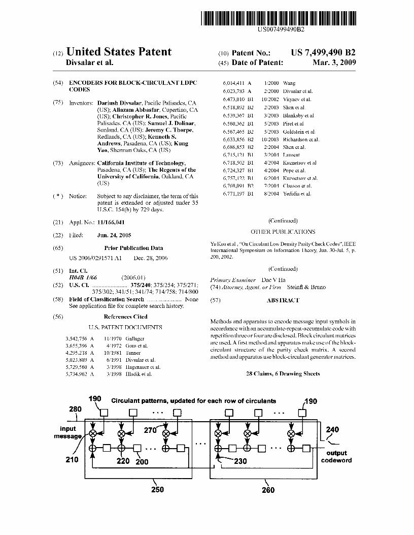
Methods and apparatus to encode message input symbols inaccordance with an accumulate-repeat-accumulate code withrepetition three or four are disclosed. Block circulant matricesare used. A first method and apparatus make use of the block-circulant structure of the parity check matrix. A secondmethod and apparatus use block-circulant generator matrices.
28 Claims, 6 Drawing Sheets
190 Circniant nafFprna_ unrlatpd fnr path rnw of r_irr_ulanfc 4 aft

US 7,499,490 B2Page 2
U.S. PATENT DOCUMENTS R.M. Tanner, "On Graph Constructions for LDPC Codes by Quasi-
6,785,863 B2 8/2004 Blankenship et al.Cyclic Extension," in Information, Coding and Mathematics (M.
6,789,227 B2 9/2004 De Souza et al. Blaum, P. Farrell, and H. van Tilborg, eds.) pp. 209-220, Kluwer, Jun.
6,803,787 B1 10/2004 Wicker, Jr. 2002.
6,829,308 B2 12/2004 Eroz et al. A Sridharan, et al., "A Construction for Low Density Parity Check6,842,872 B2 1/2005 Yedida et al. Convolutional Codes Based on Quasi-Cyclic Block Codes", in IEEE6,848,069 B1 1/2005 Levy et al. International Symposium on Information Theory p. 481, Jun. 30-Jul.6,857,097 B2 2/2005 Yedidia et al. 5, 2002.6,862,552 B2 3/2005 Goldstein et al. O. Milenkovic, "Block-Circulant Low-Density Parity-Check Codes6,888,897 B1 5/2005 Nazari et al.
for Optical Communication System" IEEE Journal of Selected Top-6,903,665 B2 6/2005 Akhter et al.7,089,477 B1 8/2006 Divsalar et al. ics in Quantum Electronics, pp. 294-299, Mar. 2004.
7,093,179 B2 8/2006 Shea J. Thorpe et al. "Methodologies for Designing LDPC Codes Using7,095,792 B2 8/2006 Doetsch et al. Photographs and Circulants," in IEEE International Symposium on7,158,589 B2 1/2007 Cameron et al. Information Theory, p. 238, Jun. 27-Jul. 2, 2004.7,191,376 B2 3/2007 Yedidia Aliazam Abbasfar et al. "Accumulate Repeat Accumulate Coded7,243,294 B1 7/2007 Divsalar et al. Modulation" IEEE Military Communications Coference, Oct.7,313,752 B2 * 12/2007 Kyung et al ................. 714/801 31-Nov. 3, 2004.7,343,539 B2 3/2008 Divsalar et al.
2005/0149845 Al* 7/2005 Shi et al. Aliazam Abbasfar et al. "Accumulate Repeat Accumulate Codes"
2005/0223305 Al* 10/2005 Kons IEEE Globecom 2004, Nov. 29-Dec. 3, 2004.
2007/0011568 Al* 1/2007 Hocevar Aliazam Abbasfar et al., "Maximum Likelihood Decoding Analysis
OTHER PUBLICATIONSof Accumulate-repeat-Accumulate Codes" IEEE Globecom 2004,Nov. 29-Dec. 3, 2004.
S. Lin, "Quasi-Cyclic LDPC Codes" CCSDS working group whitepaper, Oct. 2003. * cited by examiner

U.S. Patent Mar. 3, 2009 Sheet 1 of 6 US 7,499,490 B2
1 2 3 4 5
A B C
FIG. 1
1 2 3 4 5
A B C
FIG. 2

"*N'̂a^0
20
40
60
80
100
120
140
160
180
U.S. Patent Mar. 3, 2009
Sheet 2 of 6 US 7,499,490 B2
So Si
Pi P2 PO
0 50 100 150 200
250 300
FIG. 3
H 1H4
FIG. 4
0 2I^II2
3^'4567
016+II7
U.S. Patent Mar. 3, 2009 Sheet 3 of 6 US 7,499,490 B2
go 0 P1 0 P2)E--50)51-101 2 34567E C /;`
0
50
m
^a
150(
FIG. 5
input 80 Outputmessage
S1 codewordPuncture
50 AccumulateD
+ Permute 61+ p1'p2S O ,S 1 I13
62
70 100 Sparse matrix multipliesn.,
--'- --90
a ^ II6+II7 I+II1
II4+II5 i II2110
100(
I+III X® `
.^
0
M II3
M=512 \ \ I \\ .
II4+II5I
I \D 500 1000 1500 2000 250C
FIG. 6

U.S. Patent Mar. 3, 2009 Sheet 4 of 6 US 7,499,490 B2
00aN
OOcoT
OCOOT
COO
T
COONT
rOOCOT ^
UL
O
coO
0
COCOqT
OCON
OO o o a o 0 0 0 0 Cl 0Q Cl q C> Cl
cn °oV_
•cep•.':f'^^ - .•: 6r !
ii •.: - 'a.' !•.. - ri.f•}' =
^ :'.r. ': i': .s'y:•:r . .a r '.EE :':fi5 ?^' i?:7'- - _ •.:£ii !?:i :i':' - . •: - .!°.i{rs:::.rr':
.' 'i!' i '. : +4' j^'iur. dr ,,rr-
.;;.:.:r.?' ir`3 '.::.ice.'.-r; - -::.%:[: •.!".C]•'. _- _ ..1 •S : •Y: : '1V !'Y.-: _ - - ^.ttl! ::C
.wT-._::: . - _ _ ..Y ..r' .:Si4i iJ : - .: '_wr :ii'.y:':. ..l :i:V_:i•: .0441 .:i;,.
.e%'j••'i•'
"'r a.'•i _ ^^7' r.v^'.;.. . ,^.-i. -: jry. :ie: ^• •..r •'i'•i• _ ::fir - - •'•'':5!
y= = ".r '! iS^' r __ 7°rr :c_::' _ _ff_ ; 'r
..:v.:r'
:,':'S8:• ri =̂̀ ^ '^=*::iE r .9^s -: F' r - .':x `.. .E::•_ r. -".rpgr :^'
.tr ,i . ••.ir '^'^Ji:v i .—^^.^'• .t!.:wt: .i:: ^.: ^ -__ .E::1 .'.•[-.4^ {^:' :• ' :::.E:. ^ _ L=i^i'..1:^^ t'' r}..^.+•
-. ry`
__-'
Ji:`i '. >tr - "^i3' .̀• ^;,rg :-- -t£'''• ::$':: '-se7 "}•:'r' ; •tear:•. :%: . i= :'r^` .ar.:_ -r:v s"!^ ^.•r -9 :^^ r"r' ^ :r:<% %̂ '
_ f :.tar.^ .:if i .F E E: :.,^ . ' f:^i^ r'' .:s^::^ •r̂ . jr . ^r -:. ^'e sf': _^ ,̂ t'r. „: •. r^•` - :^ ^'°':^: .E^ .:c 'x5z ti: :i ::?i = s:'.-: ' - i^..i@^a -- ` ^'ar. ^[^ r' .. ^''a :: :Q .• ;r> _":r"
.: s.r !•!'l.:. `.• _^:.
_r .__r .sr• e:r
'''.•^ •- r^
• :.r=..
^_=r:-
=?_ d' .^^l.
__:
_^r5--:r•f
-:r.: { i.:E •'
.r
AAAy•'-
_ ^ .>'' •: errr _rr^r. .n' :. .;.: .^:-.:. • r.:•S' v"e".^ _r_ ' e, _ - :'r' s-:r? r ::.
Fl ... F _.iii i._II:.:::^ _ _ •^•: :_A:^_s -___ _- _ _- _•':':.Q'_^ n_.i' i:<: _ __
r• -
_
{ice - :. .,! ii ^• _: ' •'1... ... ..'.-ii '_ _ _

U.S. Patent Mar. 3, 2009 Sheet 5 of 6 US 7,499,490 B2
O N CD CD cc 000 O N
T— T-
O
Oto
co
CD dr LL
OOr
OOM
OON
OON
240
outputodeword
U.S. Patent Mar. 3, 2009 Sheet 6 of 6 US 7,499,490 B2
16 shift registers, reloaded with circulant patterns once per row
input T k--16Tpccaea^ 1
One conditional additionper message bit
k X k
Sytematic output codeword
FIG. 9(Prior Art)
190 Circulant natterns _ undated fnr each rnw of r_irruianlc 4an
FIG. 10

US 7,499,490 B21
ENCODERS FOR BLOCK-CIRCULANT LDPCCODES
GOVERNMENT INTEREST
The invention described herein was made in the perfor-mance of work under a NASA contract, and is subject to theprovisions of Public Law 96-517 (35 USC 202) in which theContractor has elected to retain title.
CROSS-REFERENCE TO RELATEDAPPLICATIONS
This application is filed on the same day of U.S. Pat. App.Ser. No. 11,166,040, now U.S. Pat. No. 7,343,539, for ARAType Protograph Codes", incorporated herein by reference inits entirety.
BACKGROUND
1. FieldThe present disclosure relates to encoders and encoding
methods for block-circulant low-density parity-check(LDPC) codes. In particular, a first encoder and iterativeencoding method are based on the erasure decoding algo-rithm. The computations required are well organized due tothe block-circulant structure of the parity check matrix. Asecond encoder and method use block-circulant generatormatrices. Some encoders of the second type have been imple-mented in a small Field Programmable Gate Array (FPGA)and can operate at 100 Msymbols/second.
2. Related ArtRecently, block-circulant LDPC codes have been found
that provide both excellent error correction performance andwell structured decoder architectures. Constructions havebeen presented in the following papers:.Y. Kou, H. Tang, S. Lin, and K. Abdel-Ghaffar, "On Circulant
Low Density Parity Check Codes," IEEE InternationalSymposium on Information Theory, p. 200, June 2002;
S. Lin, "Quasi-Cyclic LDPC Codes." CCSDS working groupwhite paper, Oct. 2003;
R. M. Tanner, "On Graph Constructions for LDPC Codes byQuasi- Cyclic Extension," in Information, Coding andMathematics (M. Blaum, P. Farrell, and H. van Tilborg,eds.), pp. 209-220, Kluwer, June 2002;
A. Sridharan, D. Costello, and R. M. Tanner, A Constructionfor Low Density Parity Check Convolutional Codes Basedon Quasi-Cyclic Block Codes," in IEEE InternationalSymposium on Information Theory, p. 481, June 2002;
O. Milenkovic, I. Djordjevic, and B. Vasic, "Block-CirculantLow-Density Parity-Check Codes for Optical Communi-cation Systems," IEEE Journal of Selected Topics in Quan-tum Electronics, pp. 294-299, March 2004;
J. Thorpe, K. Andrews, and S. Dolinar, "Methodologies forDesigning LDPC Codes Using Protographs and Circu-lants," in IEEE International Symposium on InformationTheory, p. 238, June 2004), and others.
All of the above papers are incorporated herein by referencein their entirety.
Error correcting codes are used to transmit informationreliably over an unreliable channel, such as a radio commu-nications link or a magnetic recording system. One class oferror correcting codes are binary block codes, where K infor-mation bits are encoded into a codeword of N symbols (N>K),the codeword is transmitted over the channel, and a decoderthen attempts to decode the received (and potentially cor-
2rupted) symbols into the original K information bits. If thechannel symbols are also binary, an encoder that uses the Kinformation bits as K of the. N channel symbols is known asa systematic encoder. These K channel symbols are called the
5 systematic symbols, and the remaining N—K symbols arecalled parity symbols. Sometimes one uses an encoder thatgenerates N+P symbols, and then P of them are discardedwhile the remaining N are transmitted over the channel. Thediscarded symbols are known as punctured symbols.
10 Many different mathematical models are used to describephysical communications channels. One model is the BinaryErasure Channel (BEC). The input alphabet is binary (either0 or 1), and the output alphabet is ternary (0, 1, or e forerasure). When a 0 is transmitted over the BEC, the received
15 symbol may be either 0 or e; similarly, a transmitted 1 isreceived either as a 1 or e. An erasure correcting decoder isused with a BEC, and its task is to reconstruct the binaryvalues that were transmitted and corrupted to the value e bythe channel. In particular, puncturing a codeword is equiva-
20 lent to transmitting it over a BEC, where each puncturedsymbol is corrupted to the value e.
Erasure correcting decoders for LDPC codes have beenstudied at length [see, for example, M. Luby, M. Mitzenma-cher, A. Shokrollahi, D. Spielman, and V. Stemann, "Practical
25 loss-resilient codes," in Proc. 29th Annual ACM Symp.Theory of Computing, 1997, pp. 150-159], and the decodingmethod described in that paper has become the standard era-sure correcting algorithm. This erasure correcting algorithmsucceeds if and only if the erased symbol positions do not
30 contain a stopping set [see T. Richardson and R. Urbanke,"Efficient Encoding of Low-Density Parity-Check Codes,IEE Trans. on Information Theory, February 2001, pp. 638-656].
U.S. Pub. App. No. 20040153934 discloses a method and35 apparatus for encoding LDPC codes.
SUMMARY
In accordance with the present disclosure, novel encoders,40 encoding methods and a hardware encoder implementation
for block-circulant LDPC codes will be presented.According to a first aspect, an encoding apparatus to
encode message input symbols in accordance with an accu-mulate-repeat-accumulate code with repetition four is dis-
45 closed, the apparatus compri sing: a first multiplier to multiplya first portion of the input symbols with a first matrix, formingfirst intermediate symbols; a second multiplier to multiply asecond portion of the input symbols with a second matrix,forming second intermediate symbols; a first adder to sum the
50 first intermediate symbols with the second intermediate sym-bols, forming third intermediate symbols; a third multiplier tomultiply the third intermediate symbols with a third matrix,forming fourth intermediate symbols; a fourth multiplier tomultiply the third intermediate symbols with a fourth matrix,
55 forming a first set of output symbols; a second adder to sumthe fourth intermediate symbols with the second portion ofthe input symbols, forming fifth intermediate symbols; a per-muter to permute the fifth intermediate symbols, formingpermuted symbols; and an accumulator to accumulate the
60 permuted symbols, forming a second set of output symbols.According to a second aspect, a method for encoding mes-
sage input symbols in accordance with an accumulate-repeat-accumulate code with repetition four is disclosed, compris-ing: multiplying a first portion of the input symbols with a first
65 matrix, forming first intermediate symbols; multiplying asecond portion of the input symbols with a second matrix,forming second intermediate symbols; adding the first inter-

US 7,499,490 B23
mediate symbols to the second intermediate symbols, form-ing third intermediate symbols; multiplying the third inter-mediate symbols with a third matrix, forming fourthintermediate symbols; multiplying the third intermediatesymbols with a fourth matrix, forming a first set of outputsymbols; adding the fourth intermediate symbols with theinput symbols, forming fifth intermediate symbols; permut-ing the fifth intermediate symbols, forming permuted sym-bols; and accumulating the permuted symbols, forming asecond set of output symbols.
According to a third aspect, an encoding apparatus toencode message input symbols in accordance with an accu-mulate-repeat-accumulate code with repetition three is dis-closed, the apparatus comprising: a puncturing device, punc-turing k input symbols and outputting k/2 input symbols,forming a first set of output symbols; a first multiplier tomultiply the k input symbols with a first matrix, forming firstintermediate symbols; a second multiplier to multiply the kinput symbols with a second matrix, forming a second set ofoutput symbols; a permuter to permute the first intermediatesymbols, forming permuted symbols; and an accumulator toaccumulate the permuted symbols, forming a third set ofoutput symbols.
According to a fourth aspect, a method for encoding mes-sage input symbols in accordance with an accumulate-repeat-accumulate code with repetition three is disclosed, compris-ing: puncturing k input symbols and outputting k/2 inputsymbols, forming a first set of output symbols; multiplyingthe k input symbols with a first matrix, forming first intenne-diate symbols; multiplying the k input symbols with a secondmatrix, forming a second set of output symbols; permutingthe first intermediate symbols, forming permuted symbols;and accumulating the permuted symbols, forming a third setof output symbols.
According to a fifth aspect, an encoding apparatus toencode input symbols in accordance with a block-circulantLDPC code is disclosed, the apparatus comprising: a pluralityof recursive convolutional encoders, each recursive convolu-tional encoder comprising storage units, multipliers andadders to encode the input symbols; and a plurality of circu-lant patterns to be fed to the recursive convolutional encoders,one set of patterns for each recursive convolutional encoder.
According to a sixth aspect, a method for encoding inputsymbols in accordance with a block-circulant LDPC code isdisclosed, comprising: providing a plurality of recursive con-volutional encoders, each recursive convolutional encodercomprising storage units, multipliers and adders; setting thestorage units to a first binary value; repeating the followingoperations: i) computing a set of circulant patterns, ii) pro-viding each recursive convolutional encoder with a binarysequence of T message bits, each message bit sent to theoutput as a codeword symbol, and each message bit beingmultiplied with a circulant pattern, summed to the result of aprevious multiplication, stored in a storage unit and shifted,until the T message bits have been encoded, until kT messagebits have been encoded; and generating an output codewordby reading the contents of the storage units of the recursiveconvolutional encoders.
4FIG. 7 shows a systematic block-circulant generator matrix
for the AR3A code.FIG. 8 shows a systematic block-circulant generator matrix
for the AR4A code.5 FIG. 9 shows a hardware implementation of a quasicyclic
encoder.FIG. 10 shows a hardware implementation of a quasicyclic
encoder using feedback shift registers.
10 DETAILED DESCRIPTION
1. IntroductionIn this section, AR3A and AR4A codes will be introduced,
15 protographs for the AR3A and AR4A codes will be shown,and block-circulant parity check matrixes for the AR3A andAR4A codes will be described.
Throughout the present description, a circulant will bedefined as a square binary matrix where each row is con-
20 structed from the previous row by a single right cyclic shift. Itwill not be required that each row has Hamming weight 1.
An rTxnT parity check matrix H can be constructed byconcatenating rxn sparse circulants of size TxT. The densityof each circulant matrix is indicated by the corresponding
25 value in an rxn base matrix H,,,,.The Tanner graph corresponding to this matrix is called a
protograph (see J. Thorpe, "Low-Density Parity-Check(LDPC) Codes Constructed from Protographs," IPN ProgressReport 42-154, JPL, August 2003). See also the "Related Art"
30 section of U.S. patent application Ser. No. 11/166,040 forARA Type Protograph Codes", incorporated herein by ref-erence in its entirety. Entries greater than 1 in the base matrixcorrespond to multiple edges in the protograph. Base matricescan be expanded into block-circulant LDPC codes by replac-
35 ing each entry in Hb,,e, with circulant containing rows of thespecified Hamming weight. The resulting codes are quasicy-clic. Alternatively, they can be expanded into less structuredcodes by replacing each entry with a sum of arbitrary permu-tation matrices.
40 AR3A and AR4A codes are described in the applicant'spatent application Ser. No. 11/166,040 for ARA Type Pro-tograph Codes", filed on the same day of the present applica-tion and incorporated herein by reference in its entirety. FIGS.1 and 2 of the present application show protographs forAR3A
45 andAR4A codes and will be used as examples throughout thepresent description. Squares represent parity check nodes andcircles represent variable nodes, where the black circles rep-resent transmitted symbols and the white circles representpunctured symbols. The designs of FIGS.1 and 2 are derived
50 from a three step encoding procedure: accumulate, repeat-by-3 (or 4), and accumulate shown by the Applicants in A.Abbasfar, D. Divsalar, and K. Yao, `Accumulate RepeatAccumulate Codes," IEEE International Symposium onInformation Theory, (Chicago, Ill.), June 2004, and U.S.
55 patent application Ser. No. 11/166,040 for ARA Type Pro-tograph Codes", both incorporated herein by reference intheir entirety. Each protograph describes a 3x5 block-circu-lant parity check matrix, and the number of parallel edgesshows the degree of the corresponding circulant.
60 In practice, these protographs cannot be directly expandedinto block-circulant codes without introducing low weightcodewords, regardless of the choice of circulants. A practicalsolution is to expand the protographs twice, first with smallpermutation matrices, such as of size 4x4 or 8x8, and then
65 with circulants to build the full code. The result is a paritycheck matrix such as the one shown in FIG. 3 for a very smallAR4A code, where each nonzero entry in the matrix is rep-
BRIEF DESCRIPTION OF THE DRAWINGS
FIG. 1 shows a protograph for an AR3A code.FIG. 2 shows a protograph for an AR4A code.FIG. 3 shows a parity check matrix for an AR4A codeFIG. 4 shows a block diagram of an AR4A encoder.FIG. 5 shows a parity check matrix for an AR3A codeFIG. 6 shows a block diagram of an AR3A encoder.

US 7,499,490 B25
resented by a dot. This code was constructed by putting theAR4A protograph variable nodes in the order (4, 2, 1, 5, 3)and check nodes in order (A, B, C) as demarcated by the solidlines, expanding with 4x4 permutations, and then expandingwith 16x16 circulants. The resulting 12x20 block-circulantstructure is emphasized by dotted lines.
2. Iterative EncodersA description of a general method for LDPC encoding can
be found in T. Richardson and R. Urbanke, "Efficient Encod-ing of Low-Density Parity-Check Codes," IEEE Transactionson Information Theory, pp. 638-656, February 2001, incor-porated herein by reference in its entirety. The present sectionwill describe a related encoding technique, called iterativeencoding, that also take advantage of the block-circulantstructure of the parity check matrix.
An encoder for any (N,K) LDPC code can be built from anerasure correcting decoder.
In accordance with the present disclosure, a set of K lin-early independent variable nodes are selected as the system-atic symbols, and these are initialized with the K informationbits to be encoded. If there are no stopping sets, then theremaining N—K parity symbols are computed iteratively withthe standard erasure correcting algorithm. Because the erasedsymbol positions are known a priori, the existence of stoppingsets is also known. This method is equivalent to Richardsonand Urbanke's low-complexity encoding algorithm whentheir variable g-0. However, differently from what shown inRichardson-Urbanke, the method according to the presentdisclosure is applied to block-circulant codes.
If H has full rank R=N—K, and this iterative encodingmethod succeeds, then each of the N—K parity check equa-tions is solved exactly once to determine one of the N—Kunknown parity symbols. For a check equation with d terms,d-2 exclusive-OR operations are required. Thus, iterativeencoding requires exactly E-2R exclusive-OR operations,where E is the number of nonzero elements in H. For anarbitrary LDPC code, the scheduling of these computationscan be complex; for block-circulant codes, they can be per-formed in well organized groups of T operations. The amountof memory required in such an encoder varies depending onthe code structure; it is sufficient to store all N code symbols.
The above process will be illustrated with the AR3A andAR4A code examples. AR3A and AR4A codes are accumu-late-repeat-accumulate codes with repetition 3 and 4, respec-tively, as described in Applicants' patent application Ser. No.11/166,040 for ARA Type Protograph Codes", filed on thesame day of the present application and incorporated hereinby reference in its entirety
2A. Iterative Encoder for AR4A CodeWhen the rows and columns of the AR4A base matrix are
reordered as (B, A, C) and (4, 2, 3, 1, 5), the followingstructure of the parity check matrix H is obtained:
2 3 1 0 0
H=00210
0 1 3 0 2
Iterative encoding begins by applying the kT=2T informa-tion symbols to the first two columns in the base matrix. Thefirst row of T check equations can be solved in parallel todetermine the third column of code symbols, and then thenext row can be solved to determine the fourth column. The 2in the lower right corner means that each remaining checkequation has two unknowns, and iterative encoding is halted
6by this stopping set. However, note that this parity checkmatrix is not full rank: the sum of the first T and last T rows ofH is the all-zero vector, independent of the circulants chosen.This means that one of the remaining T undetermined code
5 symbols can be assigned an additional information bit, anditerative encoding now completes successfully, operating (ina permuted order) as an accumulator of length T.
FIG. 4 shows a block diagram of an AR4A encoder per-forming the above described process steps. An input message
10 10 comprises 2T input symbols so and s,Symbols so are multiplied by a circulant matrix H l . Sym-
bols s, are multiplied by matrix H z . The results are summed,producing the T untransmitted parity symbols, denoted po,corresponding to the fifth column of H. The untransmitted
15 parity symbols p o are then multiplied by matrix H 3 (upperright branch of FIG. 4) and matrix H 4 (lower right branch ofFIG. 4). The matrix multiplication in the lower right branch ofFIG. 4 computes the T parity symbols denoted p i , corre-sponding to the third column of H. The matrix multiply,
20 permute (element 20), and accumulate (elements 31, 32)steps in the upper right branch of FIG. 4 compute T moreparity symbols pz . Concatenating with the input message 10gives the systematic output codeword 40.
As shown in FIG. 3, each row and each column of matrices25 H, and H4 have Hamming weight 2, and each row and each
column of matrices H z and H3 have Hamming weight 3; theseHamming weights match the corresponding entries in theAR4A base matrix.
30 2B. Iterative Encoder for AR3A CodeThe AR3A code shows somewhat different behavior. With
the same row and column ordering, the AR3A base matrix is
35 2 2 1 0 0
H= 0 1 2 1 0
01202
40 Foreseeing the problematic 2 in the lower right corner, oneredundant check equation can be constructed by summing thelast T rows of H to get the length N+P=ST vector, h=[O T 1 T OT
O T O T], where Oland 1 Trepresent strings of T zeros andT ones,respectively. This check equation shows that the first 2T vari-
45 able nodes are not linearly independent, and cannot all beassigned information bits. Instead, information bits areassigned to the first 2T-1 and to the very last variable node.Iterative encoding begins with the constructed check equationh, which computes the 2T'th code symbol as the parity of the
50 preceding T-1 symbols. Iterative encoding then proceeds tocompletion exactly as for the AR4A code.
The iterative encoding algorithm will be described picto-rially for a variation of the AR3A code. In the AR3A code ofFIG. 1, variable node 4 is connected by two edges to check
55 node B, and variable node 5 is also doubly connected to checknode C. A very similar protograph can be constructed bycrossing two of these edges, so nodes 4 and 5 are each singlyconnected to both B and C. When the columns are placed inorder (1, 4, 5, 3, 2) and rows in order (A, B, C), the protograph
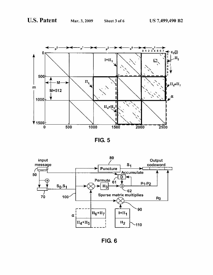
60 is expanded first by a factor of 8, and then a second time withcirculants of size 64x64, the result is the parity check matrixshown in FIG. 5. Key blocks are colored and labeled. Bysumming the bottom 2T-2M rows of the parity-check matrixin FIG. 5, we note that the 2T-2M code symbols s o, s,
65 corresponding to the rightmost 2T-2M columns must haveoverall even parity. The encoder for this variation of theAR3A code assigns k-1-2T-1 input message bits to the first

US 7,499,490 B27
2T-1 positions of so , s l , and computes the T-th bit of s, as theparity of these 2T-1 message bits. The 2T-th message bit isused to initialize the state of the accumulator in FIG. 6.
FIG. 6 shows the corresponding encoder architecture,where matrices Hl, H2, H3, U4+H5, and H6+H7 correspondto those in FIG. 5. I and Hl through H7 are permutationmatrices, so each row and each column of these matrices hasHamming weight 1. The matrices are chosen so that the sumsI+Hl, H4+H5, and H6+H7 consist entirely of rows and col-umns of weight 2. In FIG. 6, the last message bit of inputmessage 50 is replaced by the parity of the remaining messagebits, and the discarded bit is used instead to initialize theaccumulator 61, 62. On the top horizontal path through FIG.6, the puncture box 80 passes half of the k=2T bits s o, s, toserve as k/2-1 systematic symbols in the codeword. In otherwords, puncture box 80 discards s o and passes only sl.
On the bottom horizontal path, a sparse matrix multiply 90is performed between the vector 100 of k message bits and akxk/2 sparse matrix 110 comprised of matrices Hl and H2 ofFIG. 5, to generate another k/2 codeword symbols p o . On themiddle path, the k message bits 100 are multiplied by thesparse kxk matrix a of FIG. 5. The resulting k bits are re-ordered in a manner determined by H3 (see also FIG. 5), andthen accumulated into a running sequence of outputs from anexclusive-OR gate. This forms the remaining k codewordSymbols pl, p2•
Very similar algorithms are possible whenever the proto-graph can be lower triangularized as shown for theAR3A andAR4A codes, and the main diagonal consists exclusively ofthe numbers 1 and 2. Iterative encoders of this nature are notalways possible. The AR347A protograph (described later)cannot be lower-triangularized, and so iterative encoders ofthis style do not exist. Instead, the encoders described in thenext section can be used.
3. Encoders Using Block-Circulant Generator MatricesIn the present section, the construction of systematic block-
circulant generator matrices will be presented.The LDPC codes discussed here are defined by a block
matrix H composed of circulants, and of size rTxnT, wherer<n. A quasicyclic code is one for which a "quasicyclic shift"of a codeword is also a codeword. That is, if any codeword cis partitioned into binary strings of length T and each string iscircularly shifted by the same amount, the resulting vector isalso a codeword. It is immediate that any LDPC code definedby a block-circulant H matrix is quasicyclic.
In some cases, such a code has a systematic generatormatrix G of size (n-r)TxnT that is entirely composed ofcirculants. To construct such a generator matrix, the columnsof H are sorted so that the kT symbols desired to be systematicappear first, followed by the remaining rT parity symbols.That is, let H=[Q S], where Q is of size rTxkT, and S is squareand of size rTxrT. In general, if S is not full rank, then Gcannot be quasicyclic. Otherwise, G is computed as
C=11(n-r)AWQ)T]
where I („_,,)T is the identity matrix of size (n-r)Tx(n-r)T. Notall block-circulant LDPC codes have block-circulant genera-tor matrices. As a particularly small example, suppose H isdescribed by the single circulant with the first row [1 10 100 0], and size 7x7. As noted above, this only has rank 4. Onecodeword is [1 1 1 0 1 0 0], and because the code is quasi-cyclic (in fact cyclic, because H consists of a single circulant),all cyclic shifts of this codeword are also codewords. How-ever, the circulant with the first row [1 1 10 1 0 0] only hasrank 3, and so cannot be used in its entirety as a generatormatrix.
8In the remainder of this section, reference will be made
again to the AR3A and AR4A codes discussed earlier.
3A. Generator Matrix forAR3AThe 3Tx5T parity check matrix forAR3A is full rank, and
5 so a generator matrix for this code will have dimension 2T.The matrix H is partitioned into [Q S], where Q contains thecolumns to make systematic, and S is the square matrix ofparity symbols that must be invertible. If Q is chosen toinclude the circulants corresponding to variable nodes 4 and
10 2 in the protograph, as done for the iterative encoder, it can befound that S has rank rT-1, deficient by 1. This misfortuneoccurs because of the closed loop of degree-2 variable nodescreated by protograph nodes 5 and C.
Alternatively, one can choose to make protograph variable15
nodes 4 and 5 systematic. In this case, S has full rank, and asystematic block-circulant G can be calculated exactly asdescribed. When this is done for the parity check matrix inFIG. 5, the result is the generator matrix shown in FIG. 7. Anencoder that performs matrix multiplication by G is particu-
20 larly suitable for hardware implementation as described in thenext section.
3B. Generator Matrix for AR4AThe AR4A code will be now taken into consideration. For
25 this code, there is no set of R columns that can be selectedfrom H to form an invertible square matrix S, because H itselfis rank deficient by 1. Remarkably, these two defects canceland the method for constructing G can proceed with minormodifications. Variable nodes 4 and 2 are selected to be sys-
30 tematic, and when H is arranged to put these on the left, itappears as shown in FIG. 3. The left two fifths of H is thematrix Q, and the remaining square portion on the right is S.The equations are solved to find codewords of the form C4_1102T-1 p i ps p 3] and of the form cz [O T 1 OT-1 pi P
p3] where35 0 is a string of i zeros, and each px is a binary string of length
T. By expanding these solutions into circulants, a block-circulant "generator" matrix can be formed,
40 ['IC2
of size 2Tx5T. This is one dimension short, and the missing45 codeword is c=103T 1 T 0T]. Note that if c were expanded into
circulants, the resulting TxnT matrix has rank 1. For imple-mentation, it is preferable to use thi s G as the generator matrixand discard the one additional dimension in the code, accept-ing the miniscule performance loss. The generator matrix G,
50 corresponding to the parity check matrix of FIG. 3, is shownin FIG. 8. Because the last T code symbols are punctured, therightmost columns of circulants would be deleted from G inimplementation. By design, the first two columns of circu-lants form an identity matrix; the remaining circulants could
55 have been dense by the construction algorithm, but theAR4Aprotograph structure assures that many remain sparse.
3C. Generator Matrix forAR34JAA third example is the AR347A codes, built from the pro-
60 tograph,
00012
H= 2 2 1 0 1
65 1 1 1 0 2

US 7,499,490 B29
These codes do not have an iterative encoder of the formdescribed earlier, because H cannot be lower triangularized.However, quasicyclic encoders do exist. It is not hard to showthat the two columns of H chosen for systematic symbolsmust be one of the first two (identical) columns, and either thethird or the fifth column. For these choices, a quasicyclicencoder can be constructed in the usual way, just as for theAR3A code described earlier. Any other choice fails to yielda quasicyclic encoder, because it results in a rank-deficientsub-matrix S that cannot be inverted.
4. Software ImplementationThe iterative encoders described so far can often be imple-
mented efficiently in software. This is because the computa-tions can be performed in parallel, operating on T symbols ata time. Moreover, the use of circulants means that the requiredreordering of symbols is typically minimal, unlike the situa-tion with more general permutations. Preliminary resultsfrom a software implementation of this algorithm finds that itruns at 90 Kbps/MHz for several rate 1/2 AR3A codes. Inparticular, the software encoder runs at 128 Mbits/sec on a1.42 GHz Macintosh, and can be expected to run at somethinglike 1.8 Mbits/sec on a 20 MHz RAD6000 spaceflight quali-fied microprocessor.
10binary sequences describe the circulants of the generatormatrix, and so are called circulant patterns. The first set ofcirculant patterns used is given by the first row of the genera-tor matrix G, and it is stored from right to left in the boxes 190
5 across the top of FIG. 10.The first T message bits are encoded sequentially as fol-
lows. The first bit is sent directly to the output as the firstcodeword symbol. Simultaneously, the sequence stored ineach RCE 250, 260 is either Exclusive ORed with the corre-
10 sponding circulant pattern (if the message bit is a 1) or takenunmodified (if the message bit is a 0), and is right circularlyshifted one position. Then the second bit is encoded the sameway: it is taken as the second codeword symbol, and simul-taneously determines whether the circulant patterns are
15 Exclusive ORed with the contents of each RCE, before thenext right circular shift. This process is repeated until T mes-sage bits have been encoded.
Before encoding the next T message bits, a new set ofcirculant patterns are computed and provided to the RCEs.
20 Then message bits T+1 through 2T are encoded by condi-tional Exclusive OR operations and right circular shifts.These steps are repeated until all kT message bits have beenencoded.
5. Hardware Implementation 25
The systematic block-circulant generator matrices devel-oped in the previous sections are particularly amenable tohardware implementation. A hardware encoder can pass thekT message bits to the output as code symbols, while inter-nally performing a multiplication by the (dense) kx(n—k) 30
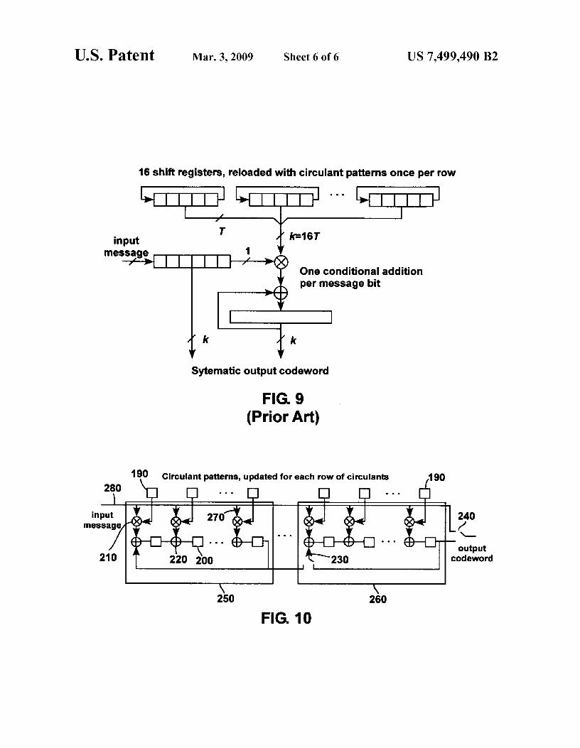
matrix in the right hand portion of G. The resulting vectorserves as the remaining (n—k)T code symbols.A direct imple-mentation of this dense matrix multiplication is shown inFIG. 9, as proposed in S. Lin, "Quasi-Cyclic LDPC Codes."CCSDS working group white paper, October 2003. The set of 35
n—k cyclic shift registers at the top of the figure, each of lengthT, are loaded with the circulant patterns for the first row of G.For each message bit m, in turn, these registers are cycledonce and, if m,-1, exclusive-ORed with the n—k symbol out-put register. When each row of circulants is completed, 40
sequences for the next row of circulants in G are loaded intothe shift registers.
In accordance with the present disclosure, an improvementin the hardware encoder is to cyclicly shift the output register,rather than the circulant registers, as shown in FIG. 10. 45
The hardware encoder of FIG. 10 comprises one-bit stor-age units 200 shown as squares, one-bit multipliers (logicalAND gates) 210 shown as circled crosses, one-bit adders(logical Exclusive OR gates) 220 shown as circled plusses,and switches 230, 240. Many of these are organized into 50
structures 250, 260 known as Recursive ConvolutionalEncoders (RCEs), as shown. For a block-circulant generatormatrix G of size kTxnT, this encoder comprises primarily n—kRCEs, each of length T.
The encoder is initialized by setting all the storage units 55
200 within the RCEs to zero, and setting the n—k switches 230as shown in the figure. Setting of the switches 230 as shown inFIG. 10 allows the contents of the last storage unit of eachRCE to be fed back to the first adder of that RCE. Thenencoding is performed in a bit-serial fashion, T bits at a time. 60
Before encoding the first T bits, each RCE is provided with abinary sequence of length T via the incoming arrows shown270 along its top edge 280. This binary sequence could becomputed and placed in the collection of (n—k)T storage units190 shown by the row of boxes across the top of FIG. 10. 65
Alternatively, the binary sequence could be provided directlyby combinatorial logic driven by a message bit counter. These
To complete generating the codeword, all n—k switches arechanged to the opposite position from that shown, and allcirculant patterns are set to zero. The contents of the n—kRCEs are then sequentially read out via right shifts as theparity portion of the codeword.
In other words, when the output switch 240 is set as drawnin FIG. 10, all kT input message bits go straight through theRCEs unchanged, and serve as output codeword symbols.Simultaneously, each message bit is multiplied by a circulantpattern, and the result is added to the shifted register contents.Then, the switch 240 is flipped and (because the other (n—k-1) switches 230 are flipped too) the daisy-chain of all (n—k)Tregisters in the RCEs are read out sequentially. The result is acodeword of length nT, of which the first kT symbols are justa copy of the input message (i.e. the encoder of FIG. 10 is asystematic encoder).
For each set of T message bits input through the input line,the circulant pattern is generally different for each of theRCEs. For example, FIG. 8 shows the block-circulant gen-erator matrix for an AR4A code. The first 128 columns of thematrix of FIG. 8 just have a diagonal line: this is an identitymatrix that passes the input bits to the output unchanged. Theremaining 192 columns comprise an 8x12 array of circulants,each of size T=16. Except for the occasional coincidence, all96 circulants are different.
This encoder has been implemented in hardware. Itrequires n—k D-latches, n—k exclusive-OR gates, and a mod-est amount of additional combinatorial logic. The size(k=1024, n=2048) LDPC code fits comfortably in a XilinxXC3S200 Spartan Field Programmable Gate Array (FPGA),and runs at 100 Msymbols/second. Speed is determined bythe maximum clock rate of the FPGA. The maximum sup-ported code size is determined primarily by the number ofD-latches required to accumulate the parity, and so scaleslinearly with n—k.
5. ConclusionAs many research groups have discovered in the last couple
years, block-circulant LDPC codes have well structureddecoders, and offer excellent error correction performancewhen designed carefully. The Applicants have shown in thepresent disclosure that block-circulant LDPC codes possessattractive encoders as well, of a couple different forms.

US 7,499,490 B211
An iterative encoder is often possible for block-circulantLDPC codes, based on the standard erasure correction algo-rithm. Due to the circulant structure of the parity checkmatrix, the computational steps are typically sparse matrixmultiplication by a circulant, permutation, and modulo-2accumulation. The circulant matrix multiplications operateon long strings of sequential bits, so parallel computations arepractical and permit fast encoders.
Encoders composed of linear feedback shift registers areanother attractive alternative for block-circulant LDPCcodes. These are based on the block-circulant generatormatrices that these LDPC codes often possess. Such anencoder requires remarkably little hardware, and provides afast, simple, bit-serial architecture. The Applicants haveimplemented these decoders in a small FPGA operating at100 Msymbols/second.
The encoders and encoding methods disclosed herein areapplicable to a wide range of communication problems. Theywould be of interest to any application that requires the excel-lent performance that LDPC codes provide, and that wouldbenefit from low-complexity LDPC encoders. Examplesinclude communications systems onboard spacecraft in deepspace or in orbit around the earth, digital encoders in cellulartelephones, encoders within data storage devices such as harddisk drives and magnetic tape recorders, and encoders withincomputer modems.
While several illustrative embodiments of the inventionhave been shown and described in the above description,numerous variations and alternative embodiments will occurto those skilled in the art. Such variations and alternativeembodiments are contemplated, and can be made withoutdeparting from the scope of the invention as defined in theappended claims.
What is claimed is:1.An encoding apparatus to encode message input symbols
in accordance with an accumulate-repeat-accumulate codewith repetition four, the apparatus comprising:
• first multiplier to multiply a first portion of the inputsymbols with a first matrix, forming first intermediatesymbols;
• second multiplier to multiply a second portion of theinput symbols with a second matrix, forming secondintermediate symbols;
• first adder to sum the first intermediate symbols with thesecond intermediate symbols, forming third intermedi-ate symbols;
• third multiplier to multiply the third intermediate sym-bols with a third matrix, forming fourth intermediatesymbols;
• fourth multiplier to multiply the third intermediate sym-bols with a fourth matrix, forming a first set of outputsymbols;
• second adder to sum the fourth intermediate symbolswith the second portion of the input symbols, formingfifth intermediate symbols;
• permuter to permute the fifth intermediate symbols,forming permuted symbols; and
an accumulator to accumulate the permuted symbols,forming a second set of output symbols.
2. The apparatus of claim 1, wherein the first portion of theinput symbols corresponds to a first half of the input symbolsand the second portion of the input symbols corresponds to asecond half of the input symbols.
3. The apparatus of claim 1, wherein output symbols areobtained by combining the first set of output symbols, thesecond set of output symbols, and the input symbols.
124. The apparatus of claim 1, wherein each row of the first
matrix has Hamming weight 2, each row of the second matrixhas Hamming weight 3, each row of the third matrix hasHamming weight 3, and each row of the fourth matrix has
5 Hamming weight 2.5. The apparatus of claim 1, wherein the first matrix, sec-
ond matrix, third matrix and fourth matrix are block-circulantmatrices.
6.A method for encoding message input symbols in accor-io dance with an accumulate-repeat-accumulate code with rep-
etition four, comprising:multiplying a first portion of the input symbols with a first
matrix, forming first intermediate symbols;multiplying a second portion of the input symbols with a
15 second matrix, forming second intermediate symbols;adding the first intermediate symbols to the second inter-
mediate symbols, forming third intermediate symbols;multiplying the third intermediate symbols with a third
matrix, forming fourth intermediate symbols;20 multiplying the third intermediate symbols with a fourth
matrix, forming a first set of output symbols;adding the fourth intermediate symbols withthe input sym-
bols, forming fifth intermediate symbols;permuting the fifth intermediate symbols, forming per-
25 muted symbols; andaccumulating the permuted symbols, forming a second set
of output symbols.7. The method of claim 6, wherein output symbols are
obtained by combining the first set of output symbols, theso second set of output symbols, and the input symbols.
8. The method of claim 6, wherein the first portion of theinput symbols corresponds to a first half of the input symbolsand the second portion of the input symbols corresponds to a
35 second half of the input symbols.9. The method of claim 6, wherein each row of the first
matrix has Hamming weight 2, each row of the second matrixhas Hamming weight 3, each row of the third matrix hasHamming weight 3, and each row of the fourth matrix has
40 Hamming weight 2.
10. The method of claim 6, wherein the first matrix, secondmatrix, third matrix and fourth matrix are block-circulantmatrices.
11. An encoding apparatus to encode message input sym-45 bols in accordance with an accumulate-repeat-accumulate
code with repetition three, the apparatus comprising:• puncturing device, puncturing k input symbols and out-
putting k/2 input symbols, forming a first set of outputsymbols;
50 a first multiplier to multiply the k input symbols with a firstmatrix, forming first intermediate symbols;
• second multiplier to multiply the k input symbols with asecond matrix, forming a second set of output symbols;
• permuter to permute the first intermediate symbols, form-55 ing permuted symbols; and
an accumulator to accumulate the permuted symbols,forming a third set of output symbols.
12. The apparatus of claim 11, wherein an output codewordis obtained by combining the first, second and third sets of
60 output symbols.13. The apparatus of claim 11, wherein the first matrix is a
block matrix of size kxk, comprising two on-diagonal sub-matrices each of size k/2 xk/2 and two off-diagonal sub-matrices eachof size k/2 xk/2, andthe second matrix is of size
65 kxk/2, k being an integer.14.The apparatus of claim 13, wherein the two on-diagonal
sub-matrices are zero and the two off-diagonal sub-matrices

US 7,499,490 B213
each have rows of Hamming weight 2, and the second matrixhas k/2 rows with Hamming weight 1 and k/2 rows withHamming weight 2.
15. The apparatus of claim 11, wherein the first matrix andthe second matrix are block-circulant matrices.
16. A method for encoding message input symbols inaccordance with an accumulate-repeat-accumulate code withrepetition three, comprising:
puncturing k input symbols and outputting k/2 input sym-bols, forming a first set of output symbols, k being aninteger;
multiplying the k input symbols with a first matrix, formingfirst intermediate symbols;
multiplying the k input symbols with a second matrix,forming a second set of output symbols;
permuting the first intermediate symbols, forming per-muted symbols; and
accumulating the permuted symbols, forming a third set ofoutput symbols.
17.The method of claim 16, further comprising combiningthe first, second and third sets of output symbols to obtain anoutput codeword.
18. The method of claim 16, wherein the first matrix is ablock matrix of size kxk, comprising two on-diagonal sub-matrices each of size k/2 xk/2 and two off-diagonal sub-matrices eachof size k/2 xk/2, andthe second matrix is of sizekxk/2.
19. The method of claim 18, wherein the two on-diagonalsub-matrices are zero and the two off-diagonal sub-matriceseach have rows of Hamming weight 2, and the second matrixhas k/2 rows with Hamming weight 1 and k/2 rows withHamming weight 2.
20. The method of claim 16, wherein the first and secondmatrix are block-circulant matrices.
21. An encoding apparatus to encode input symbols inaccordance with a block-circulant low density parity check(LDPC) code, the apparatus comprising:
a plurality of recursive convolutional encoders, each recur-sive convolutional encoder comprising storage units,multipliers and adders to encode the input symbols; and
a plurality of circulant patterns to be fed to the recursiveconvolutional encoders, one set of patterns for eachrecursive convolutional encoder.
22. The apparatus of claim 21, wherein the recursiveencoders further comprise switches, each switchhaving a first
14condition where contents of a rightmost storage unit of arecursive convolutional encoder are sent back to that recur-sive convolutional encoder and a second condition wherecontents of a rightmost storage unit are sent towards the
s output.23. The apparatus of claim 21, wherein output symbols are
obtained by combining the input symbols with the contents ofthe storage units within the recursive convolutional encoders.
24. A method for encoding input symbols in accordanceio with a block-circulant LDPC code, comprising:
providing a plurality of recursive convolutional encoders,each recursive convolutional encoder comprising stor-age units, multipliers and adders;
setting the storage units to a first binary value;is repeating the following operations:
i) computing a set of circulant patterns,ii) providing each recursive convolutional encoder with a
binary sequence of T message bits, each message bit sentto the output as a codeword symbol, and each message
20 bit being multiplied with a circulant pattern, summed tothe result of a previous multiplication, stored in a storageunit and shifted, until the T message bits have beenencoded,
until kT message bits have been encoded; and25 generating an output codeword by reading the contents of
the storage units of the recursive convolutional encod-ers,
wherein k and T are integers.25. The method of claim 24, wherein the binary sequences
so are provided through an additional plurality of storage units.26. The method of claim 24, wherein the binary sequences
are provided by combinatorial logic.27. The method of claim 24, wherein the binary sequences
correspond to circulant patterns of a generator matrix.ss 28. The method of claim 24, wherein the plurality of recur-
sive convolutional encoders comprises n-k convolutionalencoders, n being an integer, wherein n-k-1 recursive convo-lutional encoders comprise a switch, the switch having a firstcondition where the contents of the rightmost storage unit of
4o a recursive convolutional encoder are sent to the leftmostadder of that recursive convolutional encoder, and a secondcondition where the contents of the rightmost storage unit ofa recursive convolutional encoder are sent towards the output.