united states patent (19) (11) patent number: … · u.s. patent fault unit number combo cement...
TRANSCRIPT
United States Patent (19) Naegele et al.
54)
75
73) 21) 22) (51) (52)
(58)
56)
CEMENT MIXENG AND PUMPING SYSTEM AND METHOD FOR OL/GAS WELL
Inventors: Phillip N. Naegele; Ronald E. Dant; Kent J. Dieball; Stanley V. Stephenson; Paul O. Padgett, all of Duncan, Okla.
Assignee: Halliburton Company, Duncan, Okla. Appl. No.: 974,391 Filed: Nov. 10, 1992 Int. Cl. ....................... E21B33/00; G06F 15/46 U.S. C. .................................... 166/285; 364/172;
364/502 Field of Search ................ 166/285,289; 364/132,
364/172, 420, 502 References Cited
U.S. PATENT DOCUMENTS
3,61,203 12/1964 Hathorn et al. ........................ 137/8 3,379,421 4/1968 Putman ...... ... 259/154 3,908,967 9/1975 Merritt ............... . 259/153 3,940,600 2/1976 Alexander et al. 35/151.2 3,951,208 4/1976 Delano ............... . 166/285X 4,003,431 1/1977 Novotny et al. .................... 166/250 4,265,266 5/1981 Kierbow et al. ... . 137/101.19 4,327,759 5/1982 Millis ....................................... 137/3 4,353,482 10/1982 Tomlinson et al. ..................... 222/1 4,407,369 10/1983 Hutchison et al. ..., 166/285 X 4,410,106 10/1983 Kierbow et al. ... ... 222/35 4,427, 33 1/1984 Kierbow et al. ... ... 222/77 4,474,204 10/1984 West ............... ... 137/88 4,538,221 8/1985 Crain et al. ... ... 364/72 4,538,222 8/1985 Crain et al. ... ... 364/72 4,571,993 2/1986 St. Onge ........ ... 73/151 4,654,802 3/1987 Davis ............. . 364/502 4,715,721 12/1987 Walker et al. ..... ... 366/132 4,764,019 8/1988 Kaminski et al. .. ... 366/15 4,779,186 10/1988 Handke et al..... 364/72 4,850,750 7/1989 Cogbill et al.. ... 406/82 4,858,692 8/1989 Nilsen ............ 166/285 4,886,367 12/1989 Bragg et al. ... 366/32 4,916,631 4/1990 Crain et al. .... 364/502 4,918,659 4/1990 Bragget al. ... ... 366/32 4,953,097 8/1990 Crain et al. ......................... 364/502
USOO52.89877A
(11) Patent Number: 5,289,877 (45) Date of Patent: Mar. 1, 1994
5,0.4,218 5/1991 Crain et al. ......................... 364/SO2 5,027,267 6/1991 Pitts et al......... ... 364/172 5,103,908 4/1992 Allen ............ ... 166/285 5,114,239 5/1992 Allen ....................................... 366/6
OTHER PUBLICATIONS
"The Ram Recirculating Averaging Mixer for Consis tent Slurry Weight', BJ Hughes Services brochure. "Surface Cementing Equipment Mixing Systems", Hal liburton Services brochure. "New BJ PSB Precision Slurry Blender", Byron Jack son Inc. Brochure. "The Magcobar Cementing System', Magcobar Dresser Cementing Operations brochure. "Western Offshore Cementing Services', The Western Company brochure. "The Pod Has Landed', Dowell Schlumberger Pump ing Services brochure. "ARC System (Automated Remote Control)', Hal liburton Services brochure. "Automatic Proppant Control System', Halliburton Services brochure.
Primary Examiner-Thuy M. Bui Attorney, Agent, or Firm-Stephen R. Christian; E. Harrison Gilbert, III (57) ABSTRACT A system and method for mixing cement slurries at an oil or gas well site and for pumping such slurries into the well provide automatic combined and interrelated density and pumping control and selectable sequential control of predetermined mixing and pumping stages. Specific conditions automatically controlled include water rate, water pressure, slurry density, recirculating slurry pressure and downhole pump rate. Each of these conditions is the subject of a respective control loop that operates independently, but under control from a central controller. The central controller generates interrelated inlet water, inlet dry cement and outlet downhole pumping control signals responsive to ope rated-entered desired operating characteristics.
19 Claims, 8 Drawing Sheets

Sheet 2 of 8 5,289,877 Mar. 1, 1994 U.S. Patent
2/
99

Sheet 3 of 8 5,289,877 Mar. 1, 1994 U.S. Patent

U.S. Patent Mar. 1, 1994 Sheet 4 of 8 5,289,877
68 7O 72 74
foLOOOOOOiD O
7.2 44. 126 leles A. 140Nf4 diffiti 2D2)3)4][2][37][2][2);
146 142 150
U.S. Patent
FAULT
UNIT NUMBER
COMBO CEMENT UNIT INTIALIZATION NOY 6 1929 YOO COPDS
ENGLISH NTS METRIC UNTS JLAN EOUPMENT LIST TABLE 0
75000 200075000
NUMBER
Mar. 1, 1994
ENGINE TYPE - CUMMNS GCTA ENGINE RPM O ENGINE HOURS 25. ENGINE STATUS OK
TRANS TYPE - ASON MD3060 TRANS STATUS 0.
PUNP TYPE - HT350 PUMP HOURS 268 PUMPO PRESSURE OK PUMP PLUNGER UBE FAULT PUMPOL TEMP DEG F 5
SYSTEM YOTAGE 23
Sheet 5 of 8
STATUS A MESSAGE COUNT THE SEC 259
DEFAULT UNIT 75000 DATA MESS 279356
2 FAUT NODES 200075000
75000 UN OF CONTR
75000
5,289,877
UK OF BLORS UN OF INSTR
UN OF COMBO
PT-ORN P
PUMPNG PRESSVRE TOTAL 08 RATE PRESSURE (CKOUT 5000 DECK ENGINE ORME 100.
O GEAR ACT ZERO PRESS
PRESS LHIT O RATE LT 5.0 RATE CR 0.07
U.S. Patent
TUNING PARAMATERS LOOP P Et DB WATER as: 0.0 DENSITY 0.7500 00
PRELOAD WATER(VOLUME) - - - - - - 2. CEMENT VALYE START POSITION(0-0) - 20
CORRECTION & CAL FACTORS PERCETICAL EACUNITS
WATER FM 0005522 PGAL DHOLE FM 100.0 259 p1 GAL P STRKS 000 NA NA
VOLUME TOTALS STAGE OBLIFE
WATER 0.0 45 45 SLURRY 0.0 36 36. UNITS BARRELSIBARRELSBARRELS
DOWNHOLE DENSOMETER NEW SETPONTS
AUTO CA DENS FREQNO DENS WATER 0.00 LO CAL 2 6.6 BASE FLUID 3 6.75 AR 8.32
5 997 6 0.98
BASE FLUID 7 95 8.34 8 226
0 CA 9 4.27 6.64 0 000
0.00 2 0.00
RECALIBRATE
OENSITY FAULT
Mar. 1, 1994
CURRENT
8.
Sheet 6 of 8
TRANSDUCER CALIBRATION
5,289,877
TRANSOUCER ACT, ZERO SPAN SLOPE WATER PRESS RECRC PRESS PUMP PRESS LUBE TEMP
STRP CHART SETUP UPPER LOWERTABLE
PRESS PS DENS GAL RATE BBLMN
NEW SETPOTS FREQAUTO CAL
0.757. WATER
3.657BASE FLU) 30708 25265LO CAL
O O O
52520 CA 2 595 BASE FLU) 3
9 3822 5 3450 6
7 8 8.3. 9
6.6
RECALIBRATE
RECIRC DENSOMETER
DENS FREQNO
O
2
5000 0 80 8.0 5.0 0.0
CURRENT DENS FREQ 0.00 Oly. 757 6.5, 5252 6.75 595 8.32 49 997 3822 0.98 350 95 3657
2.26 30708 1.27 25265 0.00 O 0.00 O 0.00 O
DENSTY PT-ORN P
8.32
U.S. Patent Mar. 1, 1994 Sheet 7 of 8 5,289,877
AUTO JOB MANAGER SCREEN MX SAGE O MANUAL STAGING
SETPTscuRRE 3 5 6 7 O 2 3 5 6 7 STAGE NUMBER ENTER
DENSiTY GAL 500 15.00685060 5342, 1533.685060 15342, 533. SETPOINTS WATER REGGISK OO PRESS: YELD CUFTISK 9900.520 MIX RATE 851033.562479|28338|897198 st
BBL MN and ENTER
STAGE SZE BBL ACTUAL BB DIFF BB
100 7809 O6989336 8345 19739 STAGE ADVANCE PRESS:
RUNTIME HOURS MX WATER RATE st
BBLIMIN UP KEY FAULT
PRESSURE
386 3999
DENSTY RATE STAGE TOTAL SLURRYSTAGE NUMBER MAN
83 8.3 WREQ 53
0.0 FLOW MTR YELD 8 STAGE TOTAL WATER WATER RATE
00 spl. 0.0 RECRC 6X5 MAN WATER YALYE
R. list Lt." SET 00. MAN 0.0 ACT 33. DECK ENGINE RPM y t MAN 86 O AC 5. CHASSS RPM DOWN HOLE DENSITY O
88 GEAR O SAYE DATE OFF
- FAULT PT-ORN P
KO SP
U.S. Patent Mar. 1, 1994
BOOST VALYE
19th FLOW METER X
8.32 GAL WATER RATE 22 ERROR 00 BBLIN WATER YAYE 100 AUTO
CEM t YALYE 00 AUTO
MIX LEVELMAN SE : AC 74. RECRC
SET 200 PS W ACT 3.2 PS AUTO 0.0
SET OOPS ACT 09 PS AUTO 100 G). RECRC SS
PRESSURE TABLES POWER TABLES J0
HOU RS
0 - 50 -7 50 - 100 87.76 00 - 50 -3 50 - 200 -236 200 - 250 -0.6 250 - 300 -958 300 - 350 -879 350 - 400 -768
905 5.78
0 - 000 000 - 2000
2000 - 3000 3000 - 000 4000 - 5000 5000 - 6000 6000 - 7000 7000 - 8000 8000 - 9000 9000 - 0000 0000 - 000 000 - 2000 2000 - 3000 3000 - 4000 000 - 5000
-603883 0 -04626 -5252 -595 -49 -3822 -350 -3656 -30708 -25263 -6632 -697 -728 -3370 -3370
M FAULT
Sheet 8 of 8
ORAN OPEN X
LFE LFE REYS | HOURS
24 32
5,289,877
STAGE SET CURRENT D
GEAR DATA KA RATE BBLINN
5,289,877 1.
CEMENT MIXING AND PUMPING SYSTEMAND METHOD FOR OL/GAS WELL
BACKGROUND OF THE INVENTION This invention relates to systems and methods for
mixing cement slurries at oil or gas well sites and for pumping such slurries into the wells.
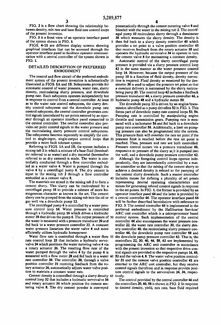
After completing the drilling of an oil or gas well, a cement slurry is typically pumped into the well to iso late the pay zone and provide support for pipe in the well. Important parameters for the cement slurry are density and pumping rate. Cement density is important for two reasons. First,
the density defines the ratio of dry cement powder to water which determines the properties of the slurry and the hydrated cement. These properties include friction pressure, setting time, cement strength, etc. Second, density also maintains proper well control through hy drostatic head of the cement column. The hydrostatic head prevents the pressurized fluids in the reservoir from producing uncontrollably into the well.
Friction pressure is also a factor of pumping rate. A high friction pressure can fracture the formation, thereby allowing the cement to flow out into the reser voir. Also, pumping time is determined by pumping rate. The slurry must be placed in the well within a specified time to prevent the cement from hardening in the drill string. Another aspect of cementing an oil or gas well is that
typically more than one type of cement slurry needs to be prepared at the well site and pumped into the well. This is done sequentially with one slurry being mixed and pumped into the well and then the next being mixed and pumped into the well, pushing the previous slurry or slurries farther into the well. Different slurries that have different densities and different compositions re quire different control parameters. The total volume of each such slurry needs to be tracked to ensure place ment of the respective slurries at desired locations in the well.
Prior systems and methods have provided automatic control of cement density but have not combined this feature with automatic pumping control. These prior systems and methods also have not provided for pre entering multiple sets of cement mixing and pumping control parameters in such a manner that permits either manual or automatic switching from one set to another for sequentially mixing and pumping different cement slurries into the well. Such a system and method for overcoming these shortcomings is needed to provide improved control of the sequential mixing and pumping of multiple types of cement slurries into an oil or gas well.
SUMMARY OF THE INVENTION
The present invention overcomes the above-noted and other shortcomings of the prior art by providing a novel and improved system and method for mixing cement slurries at an oil or gas well site and for pumping such slurries into the well. The present invention pro vides selectable sequential control of predetermined mixing and pumping stages and automatic interrelated density and pumping control within each stage. Specific conditions automatically controlled in the preferred embodiment include water rate, water pressure, slurry density, recirculating slurry pressure and downhole pump rate. Each operates independently under control
5
10
15
20
25
30
35
40
45
50
55
2 from a central controller, but such independent opera tion is performed in response to interrelated control signals generated by the controller in response to en tered desired operating characteristics.
Broadly, the present invention provides a system for mixing and pumping a cement slurry into an oil or gas well, comprising: a mixing tub; a first pump for pump ing cement slurry from the tub into the well; a base fluid flow controller for conducting a base fluid into the tub; a master controller for controlling the first pump and the flow controller so that the mixing of the cement slurry responsive to the base fluid flow controller is related to the pumping of cement slurry by the first pump into the well, the master controller including: means for defining a plurality of desired operating char acteristics; and means for generating related control signals in response to the desired operating characteris tics; means for operating the first pump in response to at least one of the control signals; and means for operating the base fluid flow controller in response to at least one of the control signals. The present invention also generally provides a
method of mixing and pumping a cement slurry into an oil or gas well, comprising: pumping water through a first control valve into a tub at the well; conducting dry cement through a second control valve into the tub; mixing the water and dry cement into a cement slurry in the tub; recirculating cement slurry out of and back into the tub; pumping cement slurry out of the tub into the well; controlling the first control valve in response to a desired water flow rate and an actual water flow rate; controlling the second control valve in response to a desired slurry density and an actual slurry density; con trolling the pumping of cement slurry in response to a desired downhole pump rate and an actual downhole pump rate; and defining the desired water flow rate, the desired slurry density and the desired downhole pump rate from an interrelated common database of predeter mined operating conditions. The present invention still further provides a method
of mixing and pumping a cement slurry into an oil or gas well, comprising: controlling, with a computer, a flow of water into a mixing tub, a flow of dry cement into the mixing tub, and a flow of resultant mixture from the mixing tub into the well; entering into the computer a plurality of operating characteristics for a plurality of different mixtures; and sequentially performing the con trolling step for at least two of the plurality of different mixtures so that at least two different mixtures are se quentially prepared in the mixing tub and placed in the well.
Therefore, from the foregoing, it is a general object of the present invention to provide a novel and im proved system and method for mixing and pumping a cement slurry into an oil or gas well. Other and further objects, features and advantages of the present inven tion will be readily apparent to those skilled in the art when the following description of the preferred em bodiment is read in conjunction with the accompanying drawings. BRIEF DESCRIPTION OF THE DRAWINGS
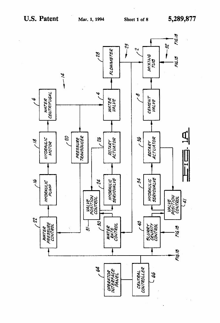
FIGS. 1A and 1B are a block diagram of the control and flow circuit of the preferred embodiment mixing and pumping system of the present invention.
5,289,877 3
FIG. 2 is a flow chart showing the relationship be tween density, mix rate and base fluid rate control loops of the present invention. -
FIG. 3 is a front view of an operator interface panel of the system shown in FIG. 1. FIGS. 4-11 are different display screens showing
graphical interfaces that can be accessed through the operator interface panel to facilitate operator communi cation with a central controller of the system shown in FIG. .
DETAILED DESCRIPTION OF PREFERRED EMBODIMENT
The control and flow circuit of the preferred embodi ment system of the present invention is schematically illustrated in FIGS. 1A and 1B. Subsystems provide for automatic control of water pressure, water rate, slurry density, recirculating slurry pressure, and downhole pump rate. Each subsystem operates independently but in response to control from a central controller. At least as to the water rate control subsystem, the slurry den sity control subsystem and the downhole pump rate control subsystem, the central controller generates con trol signals interrelated by set points entered by an oper ator through an operator interface panel connected to the central controller. The central controller also pro vides set point control signals to the water pressure and the recirculating slurry pressure control subsystems. The subsystems function separately to simplify the con trol to single-input, single-output control loops that provide a more fault tolerant system.
Referring to FIGS. 1A and 1B, the system includes a mixing tub 2 in which a mixture of a base fluid (hereinaf ter referred to as water) and a dry material (hereinafter referred to as dry cement) is made. The water is con trollably conducted through a flow controller embod ied as a water valve 4. Water is pumped through the valve 4 by a centrifugal pump 6. The dry cement is input to the mixing tub 2 through a flow controller embodied as a cement valve 8. The materials are mixed in the mixing tub 2 to form a
cement slurry. This slurry can be recirculated by a centrifugal pump 10 to provide a mixture of more ho mogeneous character as known in the art. The cement slurry can be pumped from the mixing tub into the oil or gas well via a downhole pump 12. The centrifugal pump 6 is controlled by a water pres
sure control loop 14. Water pressure is controlled through a hydraulic pump 16 which drives a hydraulic
10
15
20
25
30
35
45
motor 18 that drives the pump 6. The output pressure of 50 the water is measured with a pressure transducer 20 and fed back to a water pressure controller 22. A constant water pressure linearizes the water valve 4 and more efficiently utilizes hydraulic horsepower. Water flow rate is controlled through a water flow
rate control loop 23 that includes a hydraulic servo valve 24 which positions the water metering valve 4 via a rotary actuator 26. The resulting flow rate of the water pumped through the valve 4 by the pump 6 is measured with a flow meter 28 and fed back to a water rate controller 30. The controller 30, through a valve position controller 31 receiving feedback from the ro tary actuator 26, automatically adjusts water valve posi tion to maintain a constant water rate. Cement density is controlled through a slurry density
control loop 32 that includes a hydraulic servovalve 34 and rotary actuator 36 which position the cement me tering valve 8. The dry cement powder is conveyed
55
65
4. pneumatically through the cement metering valve 8 and blended with the water in the mixing tub 2. The centrif ugal pump 10 recirculates slurry through a densineter 38 which measures the slurry density. The density is then fed back to a slurry density controller 40 which provides a set point to a valve position controller 41 that receives feedback from the rotary actuator 35 and operates the hydraulic servovalve 34 to operate in turn the cement valve 8 for maintaining a constant density. Automatic control of the slurry centrifugal pump
pressure is provided via a slurry pressure control loop 42 in the same manner as the water pressure control loop 14. However, because the output pressure of the pump 10 is a function of fluid density, density correc tion is required. Fluid density as measured by the den simeter 38 is used to adjust the pressure set point so that a constant delivery is maintained by the slurry recircu lating pump 10. The control loop 42 includes a feedback pressure transducer 44, a slurry pressure controller 46, a hydraulic pump 48 and a hydraulic motor 50. The downhole pump 12 is driven by an engine/trans
mission identified as a pump driveline 52 in FIG.1. This forms part of downhole pump rate control loops 53, 54. Pumping rate is controlled by manipulating engine throttle and transmission gears. Pumping rate is mea sured with a tachometer 56 and fed back to a downhole pump rate controller 58. Additionally, a limit on pump ing pressure can also be programmed into the system. This pressure limit will override the rate set point if the pressure limit is reached before the rate set point is reached. Thus, pressure and rate are both controlled. Pressure control occurs via a pressure transducer 60, responsive to pressure of the slurry as it is pumped into the well, and a downhole pump pressure controller 62. Although the foregoing control loops operate inde
pendently, they are interrelatedly controlled by a mas ter controller so that the mixing of the cement slurry to achieve a desired density is related to the pumping of the cement slurry downhole. Such a master controller includes means for defining a plurality of set points representing desired operating characteristics and means for generating related control signals in response to the set points. In FIG. 1, the former is provided by an operator interface panel 64 and the latter is provided by a central controller 66. The operator interface panel 64 will be further described hereinbelow with reference to FIG. 3. The central controller 66 is implemented in the preferred embodiment by the Halliburton Services' ARC unit controller which is a microprocessor based control system. Such implementation of the central controller 66 also encompasses the water pressure con troller 22, the water rate controller 30, the slurry den sity controller 40, the recirculating slurry pressure con troller 46, the downhole pump rate controller 58 and the downhole pump pressure controller 62. That is, the controllers 22, 30, 40, 46, 58, 62 are implemented by programming the ARC unit controller in accordance with the present invention so that respective drive con trol signals are provided to the respective pumps 16, 48, 52 and the valves 4,8. The water valve position control ler 31 and the cement valve position controller 41 are external to the ARC unit controller, but they receive control signals therefrom and in response provide posi tion control signals to the servovalves 24, 34, respec tively. The control provided by the central controller 66 and
the controllers 30, 40, 58 is shown in FIG. 2. In response to desired density, yield, mix rate, base fluid required

5,289,877 5
(per volume dry material) and stage volume set points being entered through the operator interface panel 64, the central controller 66 calculates bulk cement volume, bulk cement weight, bulk fluid rate and pump time as defined by the equations shown in FIG. 2. From these, control signals are provided to the respective control loops 23, 32, 53 as indicated in FIG. 2. FIG. 2 also shows that if any one of the original input operating characteristics is changed, automatic changes in related control parameters are automatically implemented. Thus, these automatic subsystems operate indepen dently but are linked through their set points. For exam ple, when the control loops are operating automatically, a change in mix rate set point (i.e., rate for pump 12) will result in a new calculated water rate set point for the valve 4. The pressure control implemented via the controllers
10
15
22, 46, 62 is based on entered pressure criteria and a comparison thereof with actual pressure sensed by the transducers 20, 44, 60.
Preferably all of the foregoing components are imple mented using equipment known in the art. For example, the system shown in FIG.1 can be implemented using equipment from the Halliburton Services ARC control system or other Halliburton Services control systems (e.g., UNIPRO II system), except for modified com puter programming for implementing the control rela tionships described herein, including those illustrated in FIG. 2. Furthermore, the particular combination of control loops and their interrelationships shown in FIGS. 1 and 2 are unique to the field of mixing and pumping cement into an oil or gas well. The system of FIG. 1 can be installed on a truck or
other vehicle so that it can be readily transported from well site to well site as a unified system. In a particular implementation, acid tanks can also be mounted on the vehicle and the system used in an acidizing job. A specific implementation of the operator interface
panel 64 is shown in FIG. 3. This is the same interface panel as is used in the Halliburton Services ARC system except for at least some of the keys being marked with different indicia and providing different functions in response to being actuated. The keys of the specific implementation of the preferred embodiment of the present invention are as follows:
Key Reference Numeral (FIG. 3) Indicia Function
68 units Select English or metric units
70 driver tank Open/close inlet valve fill
72 pass tank fill Open/close inlet valve 74 agitator Agitator speed control 76 driver tank Open/close drain valve
drain 78 pass tank drain Open/close drain valve 80 preload density Controls initial volume
of cement 82 preload water Controls initial volume
of water 84 mix stage Advance to next stage 86 yield Yield entry 88 mix level Adjust mix level 90 mix pump Speed control for mix
pump 92 recirc pump Speed control for recirc
pump 94 On
engage
20
25
35
45
50
55
65
6 -continued
Key Reference Numeral (FIG. 3) Indicia Function open Activating key for
other functions
96 off neutral
Activating key for other close functions
98 alt Alternate keyboard function
100 error/value Select whether error or actual value is shown
102 display Select optional screen displays
104 CSOT Activates screen cursor 106 "cursor up' Cursor/speed entry
(arrow) function 108 "cursor down' Cursor/speed entry
(arrow) function 110 auto/manual Select operating mode 112 kill Quick shutdown 114 reset Reset parameters 16 enter Data entry 18 main display Return to Main Display
scree
120 LA Liquid additive pump speed control
122 LA2 Liquid additive pump speed control
24 driver tank N/A level
126 pass tank level N/A 128 Water Open
close water valve in
req'd/valve mixer 130 density cement Open/close cement valve
valve in mixer 132 mix rate Controls pump rate 134 pump l. Controls pump rate 136 pump 2 NA 138 density Set mode of density
control loop 140 low meter Select particular flow
select heter 142 hyd eng. speed Controls engine speed
driving hydraulic pump 144 "numeric keys' Data entry
(numerals' 46 "decimal point' Data entry
(...) 48 - M- Data entry 150 all Data entry
In the center of the operator interface panel 64 is a display screen 152 on which various numerical and graphical interfaces can be displayed for communicat ing with an operator of the system of the present inven tion. Examples of these graphical interfaces are shown in FIGS. 4-11.
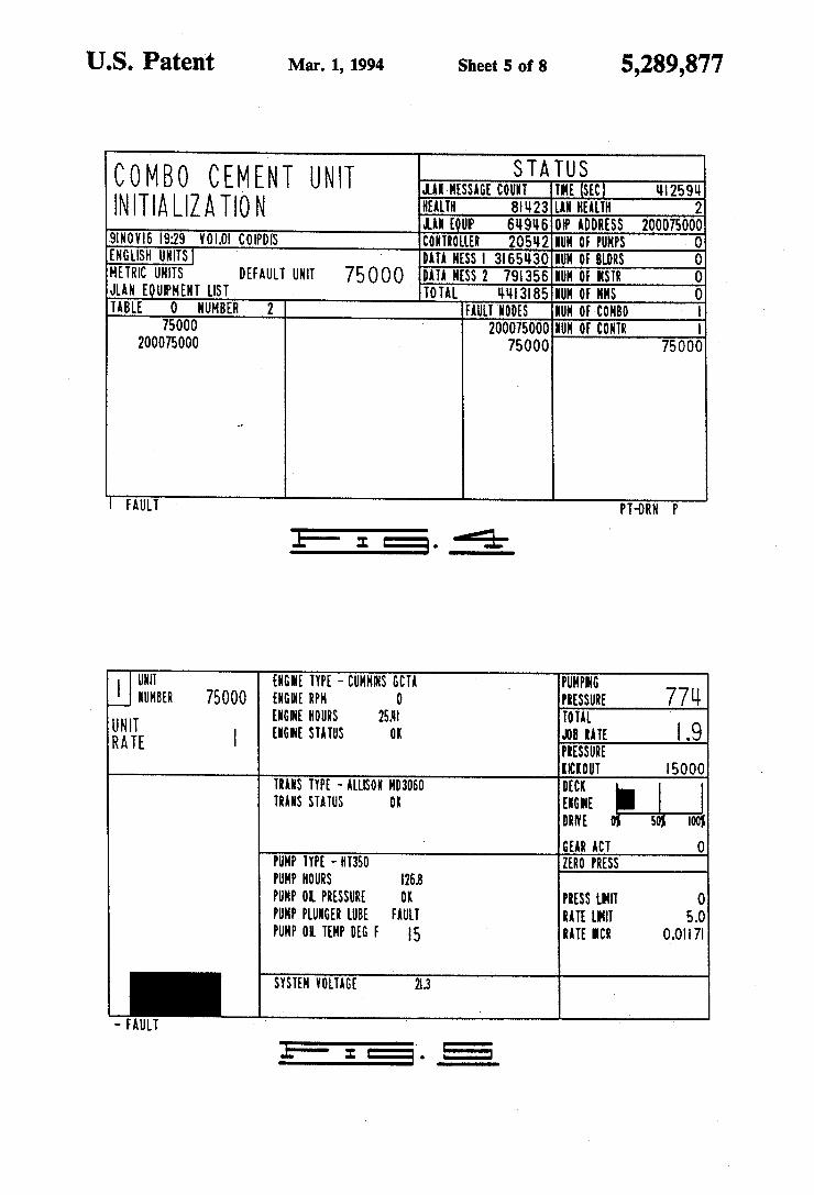
FIG. 4 shows a specific implementation of an initial ization page which first comes up when the operator interface panel 64 of the present invention is turned on. The purpose of the initialization page is to inform the operator of all controllers attached via the communica tions network and also to choose the preferred unit of operation (i.e., English Standard or metric units). A safety feature of the operator interface panel 64 is
that two keys must be pushed together to perform an operation, which prevents accidental commands. Typi cally an action key (red) is pushed with a function key (white) to make a command. Red action keys are typi cally to the left and right of the display 152. White

5,289,877 7
function keys are above and below the display 152. Only the MAIN DISPLAY key itself performs an oper ation (it brings the main display of FIG.9 to the display 152). FIG. 5 shows the graphical interface for entering
pump information relevant to the pump 12. To activate the "Pump" screen, press the DISPLAY and PUMP1 keys. The pumping set points that can be entered are pump
pressure limit, pump rate limit, and pressure kickout. The pump pressure and pump rate are limits the pump 12 will not exceed. When the pressure limit is reached, then the controller 62 automatically reduces the drive engine for the pump 12 to prevent exceeding the pres sure limit, but the pump 12 is kept on line. Pressure kickout is a safety limit. If the pressure kickout set point is reached, then the controller 62 will shift the pump driveline 52 to neutral to take the pump 12 offline. Use the CURSOR and UP/DOWN (arrow) keys to change the set points. To deactivate these functions, enter a zero. In addition to the pump set points, the downhole pressure can be zeroed out from this screen. This allows the operator to remove the offset which may occur in a pressure transducer from zero shifting.
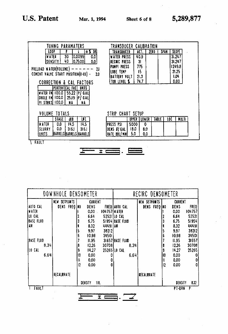
FIG. 6 is the interface screen for the transducer cali bration page by which the pressure transducers are calibrated. The "calibration' screen of FIG. 6 is activated by
pressing the DISPLAY and 2 (numeric) keys. Use the CURSOR and UP/DOWN (arrow) keys to move the highlight box to the "Zero' location under the "Trans ducer Calibration' table. Under the "Zero' column, enter a 0 to rezero the respective pressure transducer listed in the table. Do not rezero a pressure transducer with fluid in the lines as this may cause a wrong calibra tion.
Additional parameters which may need rezeroing are volume totals. Volume totals are rezeroed under the "Volume Totals' table. Other parameters on the calibration screen are fixed
and generally do not need adjusting. FIG. 7 shows the densimeter calibration page. Press
the DISPLAY and DENSITY keys to activate the SCIeet,
The "downhole densimeter' is not provided and will need calibrating. To enter calibration data for this den simeter, use the CURSOR and UP/DOWN (arrow) keys to move the highlight box to the top of the "New Set points' column of the "Downhole Densimeter' table. Holding the CURSOR button, enter the calibra tion data provided with the respective densimeter. Once the desired value is shown in the highlight box, use the CURSOR and ENTER keys to enter the value. After all the data points are entered, move the highlight box to the "Recalibrate' position and press the ENTER key. The new calibration points should appear under the "Current' column.
Additionally, a number of fluid calibrations are pro vided (see “WATER", "LOCAL”, “BASE FLUID', "AIR' in FIG. 7). To calibrate a densimeter, use the CURSOR and UP/DOWN keys to move the highlight box to the desired calibration fluid and press ENTER. This should calibrate the densimeter to the fluid density that was selected. The "Recirc Densimeter' table of the FIG. 7 screen
should already have the correct calibration data for the recirculation densimeter 38. If the calibration data is wrong, then calibrating the recirculating downhole
O
15
20
25
30
35
45
50
55
65
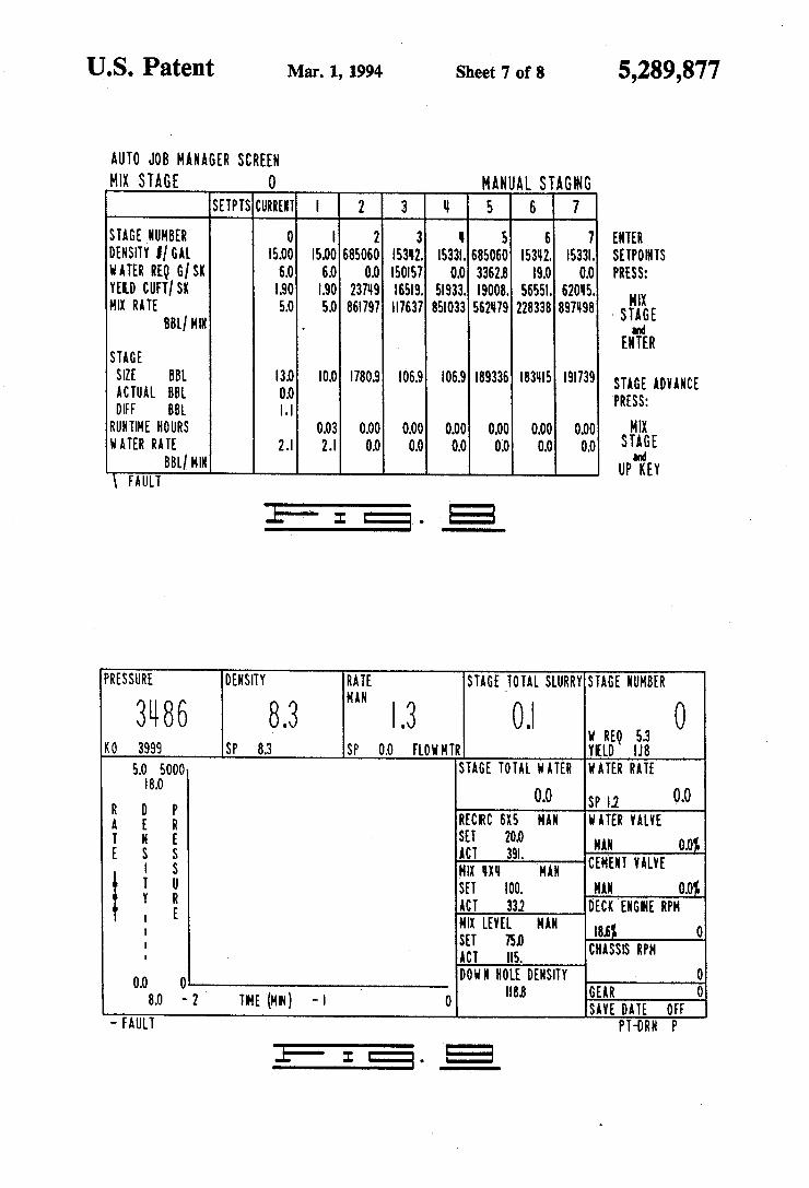
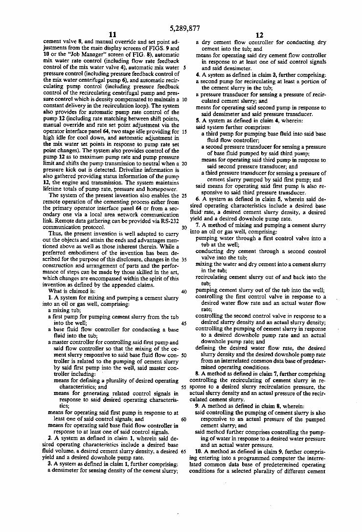
8 densimeter is done in the same manner as the downhole densineter described above. FIG. 8 shows the "Job Manager" screen through
which the operator enters, prior to the cementing job being performed, required information including stage number, desired density, desired water requirement, desired slurry yield, desired mixing rate and desired stage volume. The central controller 66 will then calcu late a required water rate for mixing. In the specific implementation illustrated in FIG. 8, space is provided for up to seven different cement blends. The controller 66 can totalize the volume of fluid pumped in each stage. This allows for automatic operation wherein the controller 66 will advance to a new stage when the programmed stage volume is reached. In manual opera tion, stages can be selected in any sequence or rese lected by the operator. When a new stage is advanced, set points for water rate, density, and pumping rate are sent to the control loops 23, 32, 53 to control the respec tive functions. Cement set points are entered before or during the
job from the "Job Manager' screen. To make the screen active, press the DISPLAY and 3 (numeric) keys. The "Job Manager' screen gives values for the current or active stage as well as all the set points for stages 1-7. Changing or entering set points for a cement job is done under the column labeled "Setpts'. To enter new set points or change existing set points, press the CURSOR key to activate a highlight box. Use the UP/DOWN (arrow) keys to move the highlight box to the desired position. When the highlight box is positioned, continue pressing the CURSOR key and enter the desired numer ical value. After entering the value, press the CURSOR and ENTER keys to store the value. Continue entering data until all the correct values are entered. The follow ing data is required:
Stage Number Density (pounds/gallon; grams/cubic meter) Water Required (gallons/sack; cubic meter/sack) Yield (cubic feet/sack; cubic meter/sack) Mixing Rate (barrels/minute; cubic meter/minute). The controller 66 calculates the correct water rate
based upon the above data. Once all the data is entered, the values are shown
under the "Setpts' column but are not stored perma nently in the correct stage and are not used as active inputs. To store the set points in the correct stage and make the set points active, press the MIX STAGE and ENTER keys. Continue entering data for as many stages as desired. To make a desired job stage current, press the MIX
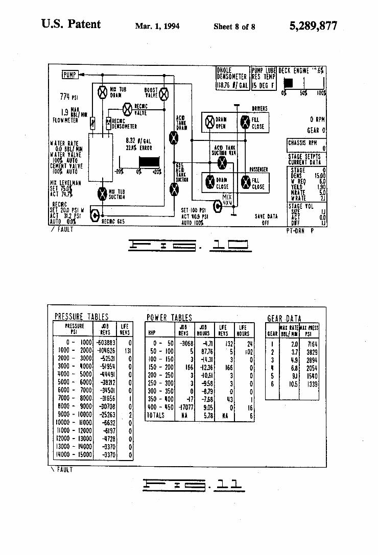
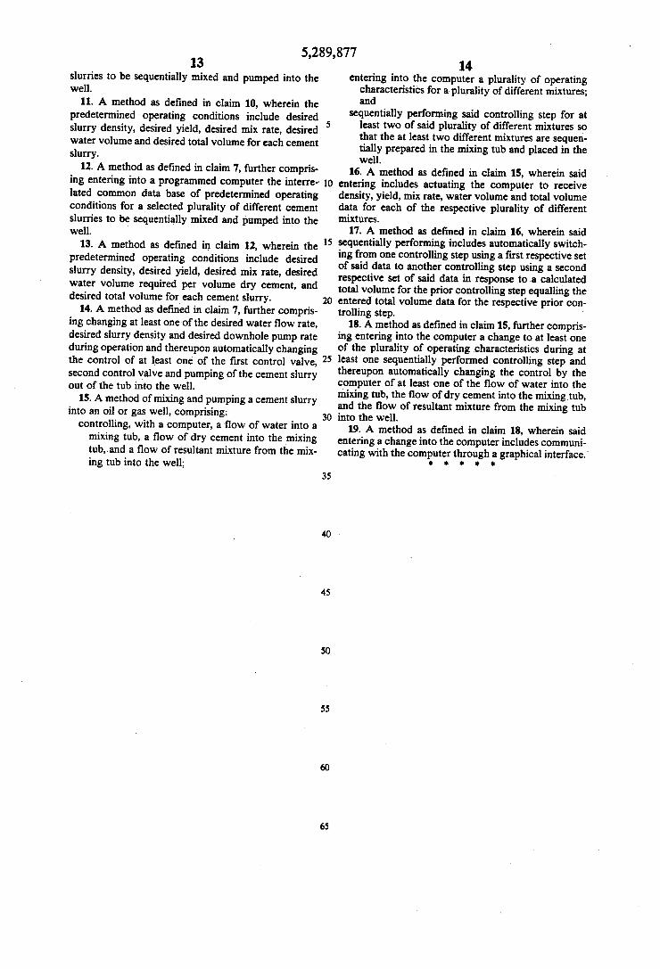
STAGE and UP keys. The controller 66 uses the cur rent set points as the active inputs. FIGS. 9 and 10 show alternative main display graphi
cal interfaces, either of which can be selected by the operator to be displayed via the display 152 of the oper ator interface panel 64. The graphical interface shown in FIG. 9 numerically designates the variously listed parameters and it also graphically displays a real time strip chart of pressure, density, rate or other user select able parameters. The graphical interface of FIG. 10 shows a computer generated flow circuit display or plumbing diagram that both graphically and numeri cally depicts operating conditions. Through either of the main display graphical interfaces, changes to the basic operating characteristics can be made "on the fly' when a cementing operation is in progress. Such changes include, for example, pressure set points for the
5,289,877 9
centrifugal pumps 6, 10 (e.g., use the CURSOR and UP/DOWN (arrow) keys to move the highlight box to the "Recirc (6X5)" or "Mix (4X4)' locations; holding the CURSOR key, enter the desired pressure set point; after the desired value is shown, press the ENTER key). A cementing operation includes, once all the requisite
data has been entered, preloading the tub, beginning the job and changing set points as described as follows.
After all the set points are entered, then the job is ready to begin. Press the MIX PUMP and AUTO/- MANUAL keys to put the mix water pump 6 in auto matic. With the mix water pump 6 engaged in manual or
automatic, preload the tub 2 with water by pressing the PRELOAD WATER and ON/ENGAGE/OPEN keys. The preload water function meters the correct amount of water into the tub 2 based upon tub volume and water requirements of the particular cement blend.
After the tub 2 is preloaded with water, the recircu lating pump 10 is turned on to bring water into the densimeter 38 and to help with mixing. Press the RE CIRC PUMP and AUTO/MANUAL keys to put the recirculating pump 10 into automatic. Note that the pressure control loop 42 on the recirculating pump 10 is density compensated in order to maintain a constant delivery. In a particular implementation, the pressure set point is based upon water; therefore, when running cement the actual pressure is higher than the set point because of the higher density of the cement. Turn on the agitator at this time to help with mixing
by pressing the AGITATOR and UP (arrow) keys. Calibrate the densimeter 38 with water if needed (see
FIG. 7). Use the CURSOR and UP/DOWN (arrow) keys to move the highlight box to the recirculating densineter location. Press the CURSOR and ENTER keys to calibrate the densimeter. The highlight box should contain the term "H2O'. With the recirculating centrifugal pump 10 running,
preload the tub 2 with cement by pressing the PRE LOAD DENSITY and ON/ENGAGE/OPEN keys. This opens the cement valve 8 to a fixed position and automatically shuts it when the desired density is reached.
After the tub 2 is preloaded, the job is ready to begin. Three ways are available to begin the job in automatic. One way is to press the MIX STAGE and AUTO/- MANUAL keys. This action places all subsystems (ex cept for the pressure loops on the centrifugals) into automatic in a predetermined order. A certain sequence is used to prevent spilling the tub. The first subsystem to begin operation is the one containing the pump 12. The pump 12 takes some time to reach the pump rate set point because of the shift schedule of the transmission. During this time the tub level will begin to drop to allow some capacity for the automatic density control subsystem. After the pump 12 has displaced a certain volume of cement, the density control subsystem will turn on the water and cement valves 4, 8 to begin put ting new water and cement into the tub 2. When using this automatic way of mixing and pumping cement slurry, the correct set points must be current. A second way includes pressing AUTO/MANUAL
and ALL to place all systems into automatic. A third way is to place subsystems into automatic
separately. First, put the pump 12 into automatic by pressing the PUMP1 and AUTO/MANUAL keys. Because of the shift schedule of the transmission, the
10
15
20
25
30
35
45
55
60
65
10 pump 12 will take some time to reach the desired rate. Allow the pump 12 to begin pumping and the tub level to drop a little before bringing cement and water into the tub. As in the other way, bringing the pump 12 on first should prevent spilling the tub 2 when bringing on the slurry. To begin bringing on cement and water, press the DENSITY and AUTO/MANUAL keys. This will place the water and cement valves 4, 8 into auto matic. Using this technique, subsystems can be individu ally put into or taken out of automatic control. As one such system is placed in manual operation and changed, the others will automatically accommodate the change in response to such others' set points and internal feed back. Changing set points during a job can be done by
advancing stages. If the "Job Manager' screen of FIG. 8 was preprogrammed, then press the MIX STAGE and UP (arrow) keys. This will place the new set points in the current stage and automatically adjust the pump rate of the pump 12, the clean water rate through the valve 4, and the density control valve 8.
If the "Job Manager” screen of FIG. 8 was not pre programmed or set point changes are desired in the current stage, then set point changes can be made via the "Job Manager' screen. Call the screen of FIG. 8 by pressing the DISPLAY and 3 (numeric) keys. Using the CURSOR and UP/DOWN (arrow) keys, enter the required information. After entering the new set points, press the MIX STAGE and ENTER keys. This will enter the new set point changes under the stage number that was programmed. Alternatively, set point changes in the current stage can be made from the Main Display (FIGS. 9 or 10). Use the CURSOR and UP/DOWN (arrow) keys to move to the desired set point location and enter a new set point. All other affected systems will be adjusted as required. For example, if a new density set point is entered, then a new yield, water requirement and water rate set point are calculated or similarly, if a new pump (mix) rate set point is entered, then a new water rate set point is calculated. The goal is to maintain equivalent mixing and pumping rates. During and after such a cementing operation, graphi
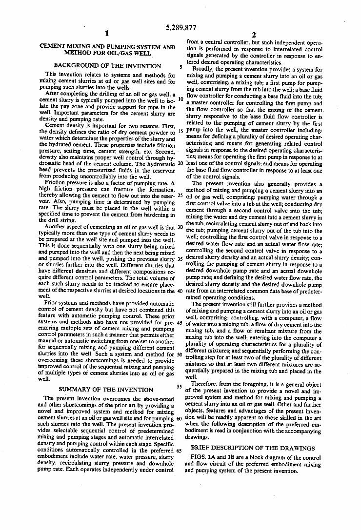
cal interfaces can be displayed through the operator interface panel 64 such as to show the pump history characteristics illustrated in FIG. 11. The foregoing can be readily implemented by pro
gramming, using known programming languages and techniques, the controller 66 in accordance with the description given hereinabove and in the drawings forming a part of this disclosure. By way of example, a program listing for functions specified therein is set forth in the accompanying Appendix. From the foregoing, it is apparent that the present
invention provides related automatic control for both mixing one or more cement slurries and pumping the slurries downhole into an oil or gas well. The system preloads water and cement by metering the correct amounts of water and dry cement powder into the mix ing tub 2 before the job begins. It allows for multiple stage information to be pre-entered before a cementing job begins whereby cementing job set point changes can be made during the cementing process. A maximum of seven job stages can be pre-stored in a specific imple mentation; however, this does not limit the number that may be utilized in other implementations. Advancing through the various stages can be done automatically or manually. The system also provides for automatic den sity control (including density feedback control of the
5,289,877 11
cement valve 8, and manual override and set point ad justments from the main display screens of FIGS. 9 and 10 or the "Job Manager' screen of FIG. 8), automatic mix water rate control (including flow rate feedback control of the mix water valve 4), automatic mix water pressure control (including pressure feedback control of the mix water centrifugal pump 6), and automatic recir culating pump control (including pressure feedback control of the recirculating centrifugal pump and pres sure control which is density compensated to maintain a constant delivery in the recirculation loop). The system also provides for automatic pump rate control of the pump 12 (including rate matching between shift points, manual override and rate set point adjustment via the operator interface panel 64, two stage idle providing for high idle for cool down, and automatic adjustment in the mix water set points in response to pump rate set point changes). The system also provides control of the pump 12 as to maximum pump rate and pump pressure limit and shifts the pump transmission to neutral when a pressure kick out is detected. Driveline information is also gathered providing status information of the pump 12, the engine and transmission. The system maintains lifetime totals of pump rate, pressure and horsepower. The system of the present invention also enables the
remote operation of the cementing process either from the primary operator interface panel 64 or from a sec ondary one via a local area network communication link. Remote data gathering can be provided via RS-232 communication protocol.
Thus, the present invention is well adapted to carry out the objects and attain the ends and advantages men tioned above as well as those inherent therein. While a preferred embodiment of the invention has been de scribed for the purpose of this disclosure, changes in the construction and arrangement of parts and the perfor mance of steps can be made by those skilled in the art, which changes are encompassed within the spirit of this invention as defined by the appended claims. What is claimed is: 1. A system for mixing and pumping a cement slurry
into an oil or gas well, comprising: a mixing tub; a first pump for pumping cement slurry from the tub
into the well; a base fluid flow controller for conducting a base
fluid into the tub; a master controller for controlling said first pump and
said flow controller so that the mixing of the ce ment slurry responsive to said base fluid flow con troller is related to the pumping of cement slurry by said first pump into the well, said master con troller including: means for defining a plurality of desired operating
characteristics; and means for generating related control signals in
response to said desired operating characteris tics;
means for operating said first pump in response to at least one of said control signals; and
means for operating said base fluid flow controller in response to at least one of said control signals.
2. A system as defined in claim 1, wherein said de sired operating characteristics include a desired base fluid volume, a desired cement slurry density, a desired yield and a desired downhole pump rate.
3. A system as defined in claim 1, further comprising: a densimeter for sensing density of the cement slurry;
12 a dry cement flow controller for conducting dry cement into the tub; and
means for operating said dry cement flow controller in response to at least one of said control signals
5 and said densimeter. 4. A system as defined in claim3, further comprising: a second pump for recirculating at least a portion of
the cement slurry in the tub; a pressure transducer for sensing a pressure of recir
culated cement slurry; and means for operating said second pump in response to
said densineter and said pressure transducer. 5. A system as defined in claim 4, wherein: said system further comprises: a third pump for pumping base fluid into said base
fluid flow controller; a second pressure transducer for sensing a pressure of base fluid pumped by said third pump;
means for operating said third pump in response to said second pressure transducer; and
a third pressure transducer for sensing a pressure of cement slurry pumped by said first pump; and
said means for operating said first pump is also re sponsive to said third pressure transducer.
6. A system as defined in claim 5, wherein said de sired operating characteristics include a desired base fluid rate, a desired cement slurry density, a desired yield and a desired downhole pump rate.
7. A method of mixing and pumping a cement slurry into an oil or gas well, comprising: pumping water through a first control valve into a
tub at the well; conducting dry cement through a second control
valve into the tub; mixing the water and dry cement into a cement slurry
in the tub; recirculating cement slurry out of and back into the
tub; pumping cement slurry out of the tub into the well; controlling the first control valve in response to a
desired water flow rate and an actual water flow rate;
controlling the second control valve in response to a desired slurry density and an actual slurry density;
controlling the pumping of cement slurry in response to a desired downhole pump rate and an actual downhole pump rate; and
defining the desired water flow rate, the desired slurry density and the desired downhole pump rate from an interrelated common database of predeter mined operating conditions.
8. A method as defined in claim 7, further comprising controlling the recirculating of cement slurry in re
55 sponse to a desired slurry recirculation pressure, the actual slurry density and an actual pressure of the recir culated cement slurry.
9. A method as defined in claim 8, wherein: said controlling the pumping of cement slurry is also
responsive to an actual pressure of the pumped cement slurry; and
said method further comprises controlling the pump ing of water in response to a desired water pressure and an actual water pressure.
10. A method as defined in claim 9, further compris ing entering into a programmed computer the interre lated common data base of predetermined operating conditions for a selected plurality of different cement
10
15
20
25
30
35
45
50
60
65
5,289,877 13 slurries to be sequentially mixed and pumped into the well.
11. A method as defined in claim 10, wherein the predetermined operating conditions include desired slurry density, desired yield, desired mix rate, desired water volume and desired total volume for each cement slurry.
12. A method as defined in claim 7, further compris ing entering into a programmed computer the interre lated common data base of predetermined operating conditions for a selected plurality of different cement slurries to be sequentially mixed and pumped into the well.
13. A method as defined in claim 12, wherein the predetermined operating conditions include desired slurry density, desired yield, desired mix rate, desired water volume required per volume dry cement, and desired total volume for each cement slurry.
14. A method as defined in claim 7, further compris ing changing at least one of the desired water flow rate, desired slurry density and desired downhole pump rate during operation and thereupon automatically changing the control of at least one of the first control valve, second control valve and pumping of the cement slurry out of the tub into the well.
15. A method of mixing and pumping a cement slurry into an oil or gas well, comprising:
controlling, with a computer, a flow of water into a mixing tub, a flow of dry cement into the mixing tub, and a flow of resultant mixture from the mix ing tub into the well;
5
O
15
20
25
30
35
50
55
65
14 entering into the computer a plurality of operating
characteristics for a plurality of different mixtures; and
sequentially performing said controlling step for at least two of said plurality of different mixtures so that the at least two different mixtures are sequen tially prepared in the mixing tub and placed in the well.
16. A method as defined in claim 15, wherein said entering includes actuating the computer to receive density, yield, mix rate, water volume and total volume data for each of the respective plurality of different mixtures.
17. A method as defined in claim 16, wherein said sequentially performing includes automatically switch ing from one controlling step using a first respective set of said data to another controlling step using a second respective set of said data in response to a calculated total volume for the prior controlling step equalling the entered total volume data for the respective prior con trolling step.
18. A method as defined in claim 15, further compris ing entering into the computer a change to at least one of the plurality of operating characteristics during at least one sequentially performed controlling step and thereupon automatically changing the control by the computer of at least one of the flow of water into the mixing tub, the flow of dry cement into the mixing tub, and the flow of resultant mixture from the mixing tub into the well.
19. A method as defined in claim 18, wherein said entering a change into the computer includes communi cating with the computer through a graphical interface.
k is sk