unit ii shallow foundation - wordpress.com subjected to concentric loading problem 1 shallow footing...
TRANSCRIPT

SRI VIDYA COLLEGE OF ENGG & TECH LECTURE NOTES 2
CE6502 FOUNDATION ENGINEERING Page 1
UNIT II
SHALLOW FOUNDATION
Introduction
A foundation is a integral part of the structure which transfer the load of the superstructure to the soil. A foundation
is that member which provides support for the structure and it's loads. It includes the soil and rock of earth's crust
and any special part of structure that serves to transmit the load into the rock or soil. The different types of the
foundations are given in fig. 4.1
Different types of footings
Fig. 4.1 Different types of footings
Methods of determining bearing capacity The various methods of computing the bearing capacity can be listed
as follows:
Presumptive Analysis
Analytical
Methods Plate
Bearing Test
Penetration Test

SRI VIDYA COLLEGE OF ENGG & TECH LECTURE NOTES 2
CE6502 FOUNDATION ENGINEERING Page 2
Modern Testing Methods

SRI VIDYA COLLEGE OF ENGG & TECH LECTURE NOTES 2
CE6502 FOUNDATION ENGINEERING Page 3
Centrifuge TestPrandtl's Analysis
Prandtl (1920) has shown that if the continuous smooth footing rests on the surface of a weightless soil possessing
cohesion and friction, the loaded soil fails as shown in figure by plastic flow along the composite surface. The
analysis is based on the assumption that a strip footing placed on the ground surface sinks vertically downwards into
the soil at failure like a punch.
Fig 4.8 Prandtl's Analysis
Prandtl analysed the problem of the penetration of a punch into a weightless material. The punch was assumed
rigid with a frictionless base. Three failure zones were considered.
Zone I is an active failure zone
Zone II is a radial shear zone
Zone III is a passive failure zone identical for
Zone1 consist of a triangular zone and its boundaries rise at an angle with the horizontal two zones on
either side represent passive Rankine zones. The boundaries of the passive Rankine zone rise at angle of with the horizontal. Zones 2 located between 1 and 3 are the radial shear zones. The bearing capacity is given by
(Prandtl 1921) as
where c is the cohesion and is the bearing capacity factor given by the expression
Reissner (1924) extended Prandtl's analysis for uniform load q per unit area acting on the ground surface. He
assumed that the shear pattern is unaltered and gave the bearing capacity expression as follows.
if , the logspiral becomes a circle and Nc is equal to ,also Nq becomes 1. Hence the bearing capacity
of such footings becomes

SRI VIDYA COLLEGE OF ENGG & TECH LECTURE NOTES 2
CE6502 FOUNDATION ENGINEERING Page 4
=5.14c+q
if q=0,
we get =2.57qu
where qu is the unconfined compressive strength.
Terzaghi's Bearing Capacity Theory Assumptions in Terzaghi's Bearing Capacity Theory
Depth of foundation is less than or equal to its width.
Base of the footing is rough.
Soil above bottom of foundation has no shear strength; is only a surcharge load against the overturning load
Surcharge upto the base of footing is considered. Load applied is vertical and non-eccentric.
The soil is homogenous and isotropic.
L/B ratio is infinite.
Fig. 4.9 Terzaghi's Bearing Capacity Theory
Consider a footing of width B and depth loaded with Q and resting on a soil of unit weight . The failure of the
zones is divided into three zones as shown below. The zone1 represents an active Rankine zone, and the zones 3 are
passive zones.the boundaries of the active Rankine zone rise at an angle of , and those of the passive
zones at with the horizontal. The zones 2 are known as zones of radial shear, because the lines that
constitute one set in the shear pattern in these zones radiate from the outer edge of the base of the footing. Since the
base of the footings is rough, the soil located between it and the two surfaces of sliding remains in a state of
equilibrium and acts as if it formed part of the footing. The surfaces ad and bd rise at to the horizontal. At the
instant of failure, the pressure on each of the surfaces ad and bd is equal to the resultant of the passive earth pressure
PP and the cohesion force Ca. since slip occurs along these faces, the resultant earth pressure acts at angle to the

SRI VIDYA COLLEGE OF ENGG & TECH LECTURE NOTES 2
CE6502 FOUNDATION ENGINEERING Page 5
normal on each face and as a consequence in a vertical direction. If the weight of the soil adb is disregarded, the
equilibrium of the footing requires that
------- (1)
The passive pressure required to produce a slip on def can be divided into two parts, and . The force
represents the resistance due to weight of the mass adef. The point of application of is located at the lower third
point of ad. The force acts at the midpoint of contact surface ad.
The value of the bearing capacity may be calculated as :
------- (2 )
by introducing into eqn(2) the following values:
Footing subjected to Concentric loading Problem 1 Shallow footing subjected to vertical load along with
moment. Design a column footing to carry a vertical load of 40 t (DL+LL) and moment of 1000 Kg-m.
i
Design of the Column.
Fig. 4.26 Concentric & Non Concentric Footing

SRI VIDYA COLLEGE OF ENGG & TECH LECTURE NOTES 2
CE6502 FOUNDATION ENGINEERING Page 6
Trial 1 Let assume b = 300 mm & D (L) = 400 mm
See chart 33 of SP-16. Assume Diameter of bar 20 mm.
It shows for this trial No Reinforcement required, but practically we have to provide reinforcement.
Trial 2
b = 250 mm, D = 300 mm.
Fig -4.27 Column Section

SRI VIDYA COLLEGE OF ENGG & TECH LECTURE NOTES 2
CE6502 FOUNDATION ENGINEERING Page 7
Design of footing
Size of the footing
Fig 4.28 Details of the coulmn
Let D=500mm
For concentric footing;
V=40 t =40*104 N, e=M/V=1000*104/40*104 =25 mm
For no tension case: Determination of L & B for different values of L & B.
L in m B in m
1.0 2.34
2.0 1.1
2.2 0.988
L=6e=150mm

SRI VIDYA COLLEGE OF ENGG & TECH LECTURE NOTES 2
CE6502 FOUNDATION ENGINEERING Page 8
Let provide footing size is 2.2 m*1.0 m.
Check:
= =16.94 t/m2
= =19.92 t/m2
iii Thickness of footing a. Wide beam shear
Factored intensity of soil pressure,
For critical section of wide beam shear: x=(2.2/2)-(0.3/2)-d=0.95-d
Assuming Pt=0.2%, and from table 16 of SP-16

SRI VIDYA COLLEGE OF ENGG & TECH LECTURE NOTES 2
CE6502 FOUNDATION ENGINEERING Page 9
0.0265d2+0.86-0.841=0
By trial and error method, d=0.45 m
Fig 4.29 Section for wide beam shear and upward earth pressure diagram Punching shear (two way shear)
Fig 4.30 Section for two way at a distance of d/2 from face of the column round
Critical area= (1.1+4d) d m2
IS: 456-1978, =250/300=0.83
Ks=(0.5+ )=1.33>1.0
Therefore Ks=1.0
=40.0*1.5=60 t/m2
(1.1+4d)*96.8=60-27.27(0.3+d) (0.25+d)
by trial and error, d=0.255 m
=450 mm, D=450+40+20/2=500 mm

SRI VIDYA COLLEGE OF ENGG & TECH LECTURE NOTES 2
CE6502 FOUNDATION ENGINEERING Page 10
Flexural reinforcement
Fig 4.31 Section for bending moment
=18.35*1.5=27.53 t/m2
=19.42*1.5=29.13 t/m2
BM= {27.53*0.5*0.952} + {(29.13-27.53)*0.95*2/3*0.95}=13.386 t.m
Table I of SP-16, =0.193%
For wide beam shear Pt=0.2%
=0.2*1000*450/100
Provide 16mm diameter torq bars @200 mm c/c in both directions. According to clause 33.3.1 of IS: 456
=2.2/1=2.2
in central band width=2/( +1)* total in short direction=2/(2.2+1)*1980=1237.5 mm2
Hence 16 mm dia @200c/c in longer direction satisfied all criteria & 16 dia @150c/c for central band.
v Check for development length

SRI VIDYA COLLEGE OF ENGG & TECH LECTURE NOTES 2
CE6502 FOUNDATION ENGINEERING Page 11
Clause 25.2.1
Now length of bars provided, (2200-300)/2= 950 mm<
Provide extra development length of 1037.5-950=87.5 mm say 90 mm on side of the footing.
VI. Transfer of load at base of column
Clause 34.4
Permissible bearing pressure, qb=0.45*15=6.75 =675 t/m2
=1*2.2=2.2 m2
=0.3*0.25=0.075 m2
=675*2.0=1350 t/m2
Footing subjected to eccentric loading Problem 2 Design a non-concentric footing with vertical load =40t and moment = 2tm. Allowable bearing
capacity=20t/m 2 . = 15 N/mm2. =415N/mm
2 .
Determination of size of column:
P = 40t. => = 40 * 1.5 = 60t.
M = 2tm. => = 2 *1.5 = 3tm.
Trial I
Let us assume footing size b= 250mm, D=350mm.

SRI VIDYA COLLEGE OF ENGG & TECH LECTURE NOTES 2
CE6502 FOUNDATION ENGINEERING Page 12
(see chart for 0.15)
Ref. Chart 33, SP-16 => or, p =0.9%
=
Provide 4 nos. 16 bars as longitudinal reinforcement and 8 stirrups @250mm c/c as transverse
reinforcement.
Determination of the size of the footing
Depth of the footing assumed as D= 500mm. For non-concentric footing ,
Area required = Adopt a rectangular footing of size 2m * 1.1m and depth 0.5m.
Eccentricity of footing = M/P= 50mm.
Fig. 4.32 Elevation and Plan of a non-concentric footing
Determination of design soil pressure

SRI VIDYA COLLEGE OF ENGG & TECH LECTURE NOTES 2
CE6502 FOUNDATION ENGINEERING Page 13
R= soi
/ (2
l reaction =P =40t.
=40 * 1.1) = 18.2 t/m2
< 20 t/m2
Therefore, = 18.2*1.5 =27.3 t/m2
.=.273 N/mm2.
Determination of depth of footing:
a. Wide beam shear:
Consider a section at a distance ‘d' from the column face in the longer direction.
Assuming =0.2% for =15N/mm2, =0.32N/mm
2.
.B.d. = .B.( –d)
0.32 * d = 0.273 * (0.875 – d)
Therefore, d = 0.403 m
b. Punching shear:
Fig. 4.33 Section for wide beam shear
Critical area for punching shear:
= 2* ( 350+d+250+d)*d = 4d(300 + d).
Clause :31.6.3.1 (IS 456:2000)
= 0.25/0.35 =0.71
= 0.5 + =1.21 >1.0
Therefore, take, =1.0.
= 0.25* (15) 0.5 =0.968 N/mm2

SRI VIDYA COLLEGE OF ENGG & TECH LECTURE NOTES 2
CE6502 FOUNDATION ENGINEERING Page 14
' = . =0.968 N/mm2
96.8 * 4d* (0.3 +d) = 60 – 27.3 *(0.35+d)8(0.25+d)
d = 0.246m.
Therefore, from the punching and wide beam shear criteria we get, ‘d” required is
Fig. 4.34 Section for wide beam shear
403 mm. D required is (403+40+20/2)=453mm <500mm (D provided). OK.
Flexural reinforcement:
Design soil pressure (q) = 27.3 t/m2
Bending moment at the face of the column in the longer direction
=27.3 * 0.87 52
/ 2 =10.45 tm/m width.
d provided = 450mm.
For singly reinforced section, table 1, SP-16, p t =0.147 N/mm2
Area of steel required =
Spacing using 16 bars = 201*1000 / 661.5 = 303 mm c/c. Provide 16 F bars as longitudinal reinforcement @ 300mm c/c in longer direction.
Cl. 33.4.1. (IS-456:2000)
B = 2.0 / 1.1 =1.82

SRI VIDYA COLLEGE OF ENGG & TECH LECTURE NOTES 2
CE6502 FOUNDATION ENGINEERING Page 15
Area of steel in the longer direction = 661.5 * 2 =1323 mm2
Area of steel in the central band =2 / (1.82 +1)* 1323 =938 mm2
Spacing = 207.6 mm.
Provide 16 bars as longitudinal reinforcement @ 200mm c/c in shorter direction in the central band. For
remaining portion provide spacing @330mm c/c.
The central band width = width of the foundation =1100mm.
Check for development length:
Cl. 26.2.1 (IS 456 :2000)
Now, length of bars provided =(2000 – 350)/2 = 825 mm.<
Extra length to be provided = (1037.5 – 825) = 212.5mm.
.
Provide development length equal to 225mm at the ends.
Transfer of load at the column footing junction :
Cl. 33.4 (IS 456:2000)
Assuming 2:1 load dispersion,
Required L = {350 + 2*500*2} =2350mm >2000mm.
Required B = {250 + 2*500*2} =2250mm >1100mm.
= 2 * 1.1 =2.2 m2.
= 0.25 * 0.35 = 0.0875 m2
Ö ( / ) = 5.01 > 2.0. Take as 2.0.
. = q b * Ö (A 1 / A 2 ) = 675 * 2 = 1350 t/m2
.
= 40*1.5/(0.25* 0.35) * { 1 + 6 *0.05 / 0.35 } = 1273 t/m2
. < 1350 t/m2
.

SRI VIDYA COLLEGE OF ENGG & TECH LECTURE NOTES 2
CE6502 FOUNDATION ENGINEERING Page 16
Therefore, the junction is safe.
Actually there is no need to extend column bars inside the footing, but as a standard practice the column bars are
extended upto a certain distance inside the footing.
Design of strap footing: Example:
The column positions are is as shown in fig. 4.35. As column one is very close to the boundary line, we have to
provide a strip footing for both footings.
Design of the column Column A:
Fig. 4.35 Strap footing
=750 KN
Let = 0.8%, so, Ax= 0.008A and Ac = 0.992A,
Where, A is the gross area of concrete.
As per clause 39.3 of IS 456-2000,
750 x 103 = (0.4 x 15 x 0.992A) + (0.67 x 415 x 0.008A)
A = 91727.4 mm2
Provide column size (300 x 300) mm
750 x 103 = 0.4 x 15 x (1- (pt/100)) x 90000 + 0.67 x 415x ( /100) x 90000
= 0.86% ,
= (0.86/100) x (300)2 = 774 mm2
Provide 4 no's tor 16 as longitudinal reinforcement with tor 8 @ 250 c/c lateral ties.
Column B:
=1500 KN Provide column size (400 x 400) mm
1500 x 103 = 0.4 x 15 x (1- ( /100)) x 160000 + 0.67 x 415x (pt/100) x 160000
= 1.24% , = (1.24/100) x (300)2 = 1985 mm2
Provide 8 no.s tor 16 as longitudinal reinforcement with tor 8 @ 250 c/c lateral ties.
Footing design

SRI VIDYA COLLEGE OF ENGG & TECH LECTURE NOTES 2
CE6502 FOUNDATION ENGINEERING Page 17
Let us assume eccentricity e = 0.9m.
Fig. 4.36 Strap footing – soil reaction
Taking moment about line ,
x 5 – x (5-e) = 0
Footing size:
For footing A:
Fig. 4.37 Footing sizes
= 2(0.9+0.3) =2.4m.
Assume overall thickness of footing, D = 600mm.
For footing B:

SRI VIDYA COLLEGE OF ENGG & TECH LECTURE NOTES 2
CE6502 FOUNDATION ENGINEERING Page 18
me square footing of size ,
Assu
=
= 2.13m
Provide (2.2 x 2.2)m footing.
Analysis of footing
Fig. 4.38 Analysis of footing
Thickness of footing i) Wide beam shear: For footing A:

SRI VIDYA COLLEGE OF ENGG & TECH LECTURE NOTES 2
CE6502 FOUNDATION ENGINEERING Page 19
%,
Let us assume = 0.2
so from table 16 of IS456,
Assume in direction of , width of strap beam (b) is 500 mm.
Fig. 4.39 Wide beam shear for footing A
Shear = b d = qu (0.4 - d)
For footing B:
Let us assume (%) = 0.2%, so from table 16 of IS456,
Assume in direction of , width of strap beam (b) is 500 mm.
SRI VIDYA COLLEGE OF ENGG & TECH LECTURE NOTES 2
CE6502 FOUNDATION ENGINEERING Page 20
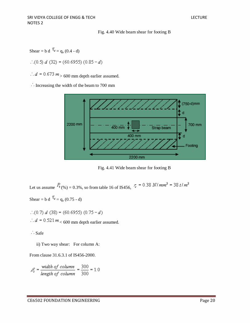
Fig. 4.40 Wide beam shear for footing B
Shear = b d = qu (0.4 - d)
> 600 mm depth earlier assumed.
Increasing the width of the beam to 700 mm
Fig. 4.41 Wide beam shear for footing B
Let us assume (%) = 0.3%, so from table 16 of IS456,
Shear = b d = qu (0.75 - d)
< 600 mm depth earlier assumed.
Safe
ii) Two way shear: For column A:
From clause 31.6.3.1 of IS456-2000.

SRI VIDYA COLLEGE OF ENGG & TECH LECTURE NOTES 2
CE6502 FOUNDATION ENGINEERING Page 21
Critical perimeter x d x = – x (critical area – dotted area in fig. 4.42)
So, shear equation becomes,
Critical perimeter x d x = – x (critical area – dotted area in fig. 4.42)
2 (0.75+1.5d) d (96.8) = 75 – 38.1125 (0.3 + 0.15 + 0.5d)
d = 0.246 mm < 600 mm.
Fig. 4.42 Wide beam shear for footing A
For column B: From clause 31.6.3.1 of IS456-2000.
Critical perimeter = 2 (0.4+d+0.4+d) = 4 (0.4+d)
So, shear equation becomes,
Critical perimeter x d x = – x (critical area – dotted area in fig. 4.43)

SRI VIDYA COLLEGE OF ENGG & TECH LECTURE NOTES 2
CE6502 FOUNDATION ENGINEERING Page 22
2 (0.4+d) d (96.8) = 150 – 60.6955 (0.4 + d)
d = 0.355 mm < 600 mm. Among all the required d values (for wide beam shear and two way shear criteria),
Max. = 521 mm.
= 521 + (20/2) + 40 = 571 mm
So, provide D = 600 mm
= 550 mm
Reinforcement for flexure for footings (i) Design along the length direction: Comparing the moments at the
column faces in both the footings (A & B),
= 24.61 tm (for Footing B)
From table 1 of SP-16, = 0.242 % (ii) Design along the width direction:
(=38.1125 t/m) < (=60.695 t/m)
So, for design along width direction footing B ( ) is considered.
Fig. 4.44 Bending along the width of footing B
So, = 0.242 % i. e. same as reinforcement along longer direction.
But. From wide beam criteria = 0.3 %,
(required) = (0.3/100) x (103) x (550) = 1650 mm2.
Provide 20 Tor @ 175 c/c along both directions at bottom face of the footing A and B.
Design of strap beam (i) Reinforcement for flexture:

SRI VIDYA COLLEGE OF ENGG & TECH LECTURE NOTES 2
CE6502 FOUNDATION ENGINEERING Page 23
= 51.294 tm (Refer fig. 4.45)
om
=
Fr table 49 of SP-16, d'/d = 50/550 = 0.1,
0.83 % and Pc= 0.12 %
(required on tension face) = (0.83/100) x 700 x 550 = 3195.5 mm2,
(required on compression face) = (0.12/100) x 700 x 550 = 462 mm2,
Provide (6+5=) 11 no.s Tor 20 at top of the strap beam and 4 no.s Tor 20 at bottom of the strap beam.
(ii) Check for shear:
Vmax = 83.235 t
< max = 2.5 N/mm2
(for M15)
(provided) =
From table 61 of SP-16, = 0.57 N/mm2
But, provide shear reinforcement for shear = ( acting – ) = 1.592 N/mm2= Vus
= 11.144 KN/cm
From table 16 of SP-16, using 4L stirrups, (Vus/d) = (11.144/2) = 5.572 KN/cm
From table 62 of SP-16, provide 4L-stirrups 10 Tor @ 100 c/c near the column (upto distance of d=550mm from
column face) and 4L-stirrups 10 Tor @ 250 c/c for other portions.
Check for development length
From clause 25.2.1 of IS456-2000,
Development length = =
For column A:
Length of the bar provided = 150-40 = 110mm <
By providing 2 no.s 90o
bend the extra length to be provided = (1297-110-3(8 x 20)) = 707 mm.
In B direction length of the bar provided =
Providing two 90o
bend, the extra length to be provided = (1297-460-2(8 x 20)) = 517 mm.
(ii) Check for shear:

SRI VIDYA COLLEGE OF ENGG & TECH LECTURE NOTES 2
CE6502 FOUNDATION ENGINEERING Page 24
Vmax = 83.235 t
But, provide shear reinforcement for shear = ( acting –
< max = 2.5 N/mm2
(for M15)
(provided) =
From table 61 of SP-16, = 0.57 N/mm2
) = 1.592 N/mm2= Vus
= 11.144 KN/cm
From table 16 of SP-16, using 4L stirrups, (Vus/d) = (11.144/2) = 5.572 KN/cm
From table 62 of SP-16, provide 4L-stirrups 10 Tor @ 100 c/c near the column (upto distance of d=550mm from
column face) and 4L-stirrups 10 Tor @ 250 c/c for other portions.
Check for development length
From clause 25.2.1 of IS456-2000,
Development length = =
For column A:
Length of the bar provided = 150-40 = 110mm <
By providing 2 no.s 90o
bend the extra length to be provided = (1297-110-3(8 x 20)) = 707 mm.
In B direction length of the bar provided =
Providing two 90o
bend, the extra length to be provided = (1297-460-2(8 x 20)) = 517 mm.
For column B:
Fig. 4.45 Development length for footing A

SRI VIDYA COLLEGE OF ENGG & TECH LECTURE NOTES 2
CE6502 FOUNDATION ENGINEERING Page 25
Le
ngth of the bar provided =
Providing one 90o
bend, the extra length to be provided = (1297-860- (8 x 20)) = 277 mm.
Fig. 4.46 Development length for footing B (Along the length and width)
Transfer of load at base of the column: For footing A:
From clause 34.4 of IS456-2000, permissible bearing stress ( )=
= (150+300+1200)(1300)= 2145000 mm2
= (300 x 300) = 90000 mm2
= 2 x 0.45 x x1500 = 1161 t//m
2
= (load on column/area of column) = (1.5 x 50)/(0.3)2 = 833.3 t//m2< Safe.

SRI VIDYA COLLEGE OF ENGG & TECH LECTURE NOTES 2
CE6502 FOUNDATION ENGINEERING Page 26
Fig. 4.47 Area of footing A considered for check of transfer of load at column base
For Footing B: From clause 34.4 of IS456-2000, permissible bearing stress ( )=
= (2200)2= 4840000 mm
2
= (400 x 400) = 160000 mm2
Fig. 4.48 Area of footing B considered for check of transfer of load at column base
= 2 x 0.45 x x1500 = 1161 t/m2

SRI VIDYA COLLEGE OF ENGG & TECH LECTURE NOTES 2
CE6502 FOUNDATION ENGINEERING Page 27
= (load on column/area of column)
= (1.5 x 100)/(0.4)2
=937.5 <